WO2012164810A1 - Fourier transform spectrometer and fourier transform spectroscopy method - Google Patents
Fourier transform spectrometer and fourier transform spectroscopy method Download PDFInfo
- Publication number
- WO2012164810A1 WO2012164810A1 PCT/JP2012/002577 JP2012002577W WO2012164810A1 WO 2012164810 A1 WO2012164810 A1 WO 2012164810A1 JP 2012002577 W JP2012002577 W JP 2012002577W WO 2012164810 A1 WO2012164810 A1 WO 2012164810A1
- Authority
- WO
- WIPO (PCT)
- Prior art keywords
- light
- output
- fourier transform
- unit
- measurement
- Prior art date
Links
- 238000000034 method Methods 0.000 title description 7
- 238000009615 fourier-transform spectroscopy Methods 0.000 title 1
- 230000003287 optical effect Effects 0.000 claims abstract description 179
- 238000001228 spectrum Methods 0.000 claims abstract description 63
- 238000004364 calculation method Methods 0.000 claims abstract description 62
- 238000005259 measurement Methods 0.000 claims description 259
- 238000000605 extraction Methods 0.000 claims description 74
- 238000001514 detection method Methods 0.000 claims description 50
- 238000004611 spectroscopical analysis Methods 0.000 claims description 19
- 230000010354 integration Effects 0.000 claims description 17
- 230000001131 transforming effect Effects 0.000 claims description 9
- 239000004065 semiconductor Substances 0.000 claims description 4
- 239000000284 extract Substances 0.000 abstract description 10
- 230000001186 cumulative effect Effects 0.000 abstract 1
- 238000006243 chemical reaction Methods 0.000 description 26
- 238000010586 diagram Methods 0.000 description 17
- 230000006870 function Effects 0.000 description 14
- 238000012545 processing Methods 0.000 description 13
- 238000005070 sampling Methods 0.000 description 13
- 230000003321 amplification Effects 0.000 description 8
- 230000008859 change Effects 0.000 description 8
- 238000003199 nucleic acid amplification method Methods 0.000 description 8
- 239000013256 coordination polymer Substances 0.000 description 7
- 230000015654 memory Effects 0.000 description 4
- 238000005314 correlation function Methods 0.000 description 3
- 230000007423 decrease Effects 0.000 description 3
- 238000005516 engineering process Methods 0.000 description 3
- 230000007246 mechanism Effects 0.000 description 3
- 230000002093 peripheral effect Effects 0.000 description 3
- 230000010365 information processing Effects 0.000 description 2
- 238000012986 modification Methods 0.000 description 2
- 230000004048 modification Effects 0.000 description 2
- 229910000530 Gallium indium arsenide Inorganic materials 0.000 description 1
- XUIMIQQOPSSXEZ-UHFFFAOYSA-N Silicon Chemical compound [Si] XUIMIQQOPSSXEZ-UHFFFAOYSA-N 0.000 description 1
- 238000013459 approach Methods 0.000 description 1
- 239000003990 capacitor Substances 0.000 description 1
- 239000002131 composite material Substances 0.000 description 1
- 230000001678 irradiating effect Effects 0.000 description 1
- 238000005457 optimization Methods 0.000 description 1
- 229910052710 silicon Inorganic materials 0.000 description 1
- 239000010703 silicon Substances 0.000 description 1
- 230000003936 working memory Effects 0.000 description 1
Images


Classifications
-
- G—PHYSICS
- G01—MEASURING; TESTING
- G01J—MEASUREMENT OF INTENSITY, VELOCITY, SPECTRAL CONTENT, POLARISATION, PHASE OR PULSE CHARACTERISTICS OF INFRARED, VISIBLE OR ULTRAVIOLET LIGHT; COLORIMETRY; RADIATION PYROMETRY
- G01J3/00—Spectrometry; Spectrophotometry; Monochromators; Measuring colours
- G01J3/28—Investigating the spectrum
- G01J3/45—Interferometric spectrometry
- G01J3/453—Interferometric spectrometry by correlation of the amplitudes
- G01J3/4535—Devices with moving mirror
Definitions
- the present invention relates to a Fourier transform spectrometer and a Fourier transform spectroscopic method, and is particularly suitable for generating an interferogram used to obtain a spectrum of measured light by integrating a plurality of interferograms.
- the present invention relates to a Fourier transform spectrometer and a Fourier transform spectroscopic method capable of integrating a plurality of interferograms.
- the spectrometer is a device that measures the spectrum of the light to be measured, one of which is an interferometer that measures the interference light of the light to be measured, and Fourier transforms the measurement result to obtain the spectrum of the light to be measured. There is a Fourier transform spectrometer that calculates
- the output of the interferometer is a composite waveform in which light of a plurality of wavelengths included in the light to be measured is collectively interfered by the interferometer, and is generally called an interferogram.
- the spectrum of the light to be measured is obtained by Fourier transforming the interferogram.
- This interferogram has a profile that has one or a plurality of steep peaks in a predetermined range and a substantially zero level in the remaining range, and the center peak of the one or more steep peaks has a center burst. Called.
- a Fourier transform spectrometer when the spectrum of the light to be measured is obtained by Fourier transforming the interferogram obtained in one measurement, the signal-to-noise ratio is usually poor and results with good accuracy can be obtained. hard. For this reason, in a Fourier transform spectrometer, an interferogram is measured a plurality of times for one measurement object, and the plurality of interferograms are integrated to obtain a spectrum of light to be measured. An interferogram (hereinafter referred to as “integrated interferogram”) is generated. These measurements are usually performed while continuously changing the optical path length of one of the two optical paths of the interferometer.
- Patent Document 1 A technique for integrating such a plurality of interferograms is disclosed in, for example, Patent Document 1 and Patent Document 2.
- the interferogram integrating device disclosed in Patent Document 1 is an interferogram integrating device that integrates a plurality of unit interferograms obtained by irradiating an object to be measured with one scan of interference light, the unit interferogram.
- a unit interferogram storage means for temporarily storing a gram, a maximum position detection means for detecting a center burst position from unit interferogram data stored in the unit interferogram storage means, and a maximum position detection means
- the unit interferogram is cut in predetermined amounts on both sides on the position axis of the unit interferogram, and a cutting means for collecting the cut interferogram, and a plurality of cutting means Obtained sequentially corresponding to the unit interferogram And a integrator for integrating the cut interferogram number.
- a measurement light interferogram generated when measurement light passes through the measurement target and a reference light interferogram generated by bypassing the measurement target are measured in synchronization with each other.
- the phase difference that most closely matches the phase of the reference light interferogram in the current measurement cycle is calculated with respect to the reference light interferogram that is stored in advance in the reference waveform storage unit.
- the average of the measurement light interferogram and the reference light interferogram is obtained by synchronously adding based on the obtained phase difference.
- measurement data in a range including the center burst is extracted from a plurality of measurement data (measurement data at each sampling point) obtained by one measurement, and then the measurement of the same optical path difference is performed. Data is found, and then the measured data with the same optical path difference are added together.
- the present invention has been made in view of the above-described circumstances, and its object is to suitably integrate a plurality of interferograms by more appropriately extracting measurement data in a range including the interferogram.
- a Fourier transform type spectrometer and a Fourier transform type spectroscopic method are provided.
- a plurality of interferograms generated by an interferometer that generates an optical path difference between two optical paths by using vibrations are integrated and obtained by this.
- the spectrum of the light to be measured is obtained by Fourier transforming the obtained integrated interferogram.
- the predetermined range to be extracted is set according to the amplitude information of the vibration. For this reason, the Fourier transform spectrometer and the Fourier transform spectroscopic method having such a configuration can take out the measurement data in a range including the interferogram more appropriately because the amplitude information of the vibration is taken into consideration. Therefore, a plurality of interferograms can be preferably integrated.
- FIG. 1st Embodiment It is a block diagram which shows the structure of the Fourier-transform type spectrometer in 1st Embodiment. It is a figure which mainly shows the structure of the interferometer in a Fourier-transform type spectrometer.
- mold spectrometer it is a figure which shows the waveform (interferogram) of the interference light of the to-be-measured light measured as an example.
- mold spectrometer it is a figure which shows the interference waveform of the laser beam of the light source for position measurement measured as an example. It is a figure for demonstrating the predetermined range taken out by an extraction part. It is a figure which shows the relationship between an interferogram and a window function.
- FIG. (1) shows the structure of the Fourier-transform type spectrometer in 2nd Embodiment. It is a figure which shows the spectrum of the laser beam radiated
- mold spectrometer it is a figure which shows the interference waveform of the laser beam with the predetermined
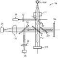
- FIG. 1 is a block diagram showing a configuration of a Fourier transform spectrometer in the first embodiment.
- FIG. 2 is a diagram mainly showing the configuration of the interferometer in the Fourier transform spectrometer.
- the Fourier transform spectrometer Da is an apparatus for measuring the spectrum of the light to be measured as a measurement object, and measures the light to be measured with an interferometer, and the interference light of the measured light to be measured.
- This is a device for obtaining the spectrum of the light to be measured by Fourier transforming the waveform (interferogram).
- the transform target to be Fourier transformed to obtain the spectrum of the light to be measured is An integrated interferogram obtained by integrating a plurality of interferograms of the light to be measured generated by an interferometer is used. For example, as shown in FIGS.
- such a Fourier transform spectrometer Da receives light (measurement light) emitted from the measurement target object SM and emits interference light of the measurement light.
- the interferometer 11 that receives the interference light of the light to be measured obtained by the interferometer 11, and an electric signal of the waveform of the interference light of the light to be measured by photoelectric conversion (represents a change in light intensity in the interference light of the light to be measured)
- a light reception processing unit 20 that outputs an electrical signal
- a position detection processing unit 30a that detects the position of the movable mirror 115 of the interferometer 11, a control calculation unit 41a, an input unit 42, and an output unit 43.
- the measurement object SM may be a light source that emits light by itself, and is irradiated with light emitted from another light source, and radiates light by reflecting, transmitting, or re-radiating the light (for example, fluorescence emission). You may do.
- the interferometer 11 receives measurement light to be measured, branches the incident measurement light into two first and second measurement lights, and the branched first and second measurement lights. Each travels (propagates) in the first and second optical paths, which are two different paths, and merges again. From this branch point (branch position), a merge point (merging position, interference position). If there is an optical path difference between the first and second optical paths until then, a phase difference is generated at the time of merging, so that interference fringes are generated by the merging.
- an interferometer having various types of first and second optical paths such as a Mach-Zehnder interferometer can be used. In this embodiment, as shown in FIG. It is constituted by.
- the interferometer 11 includes a semi-transparent mirror 112, a fixed mirror 114, and a movable mirror 115 whose light reflecting surface moves in the optical axis direction as a plurality of optical elements.
- the mirror 114 and the movable mirror 115 are arranged so that the normals of each mirror surface are orthogonal to each other, and the semi-transparent mirror 112 is an orthogonal point of each normal of the fixed mirror 114 and the movable mirror 115. It is arranged so that each of these normals intersects at an angle of 45 degrees.
- the light to be measured incident on the interferometer 11 is branched into two first and second light to be measured by the semi-transparent mirror 112.
- the branched first first measured light is reflected by the semi-transparent mirror 112 and enters the fixed mirror 114.
- the first light to be measured is reflected by the fixed mirror 114 and returns to the semi-transparent mirror 112 again following the optical path that has come.
- the other branched second measured light passes through the semi-transparent mirror 112 and enters the movable mirror 115.
- This second light to be measured is reflected by the movable mirror 115, and reversely follows the optical path that has come to return to the semi-transparent mirror 112 again.
- the first light to be measured reflected by the fixed mirror 114 and the second light to be measured reflected by the moving mirror 115 are merged with each other by the semi-transparent mirror 112 and interfere with each other.
- the light to be measured is incident on the interferometer 11 along the normal direction on the mirror surface of the movable mirror 115, and the interference light of the light to be measured is reflected on the mirror surface of the fixed mirror 114.
- the light is emitted from the interferometer 11 along the normal direction.
- the interferometer 11 is arranged on the reflection side of the semi-transparent mirror 112 reflected by the semi-transparent mirror 112 when the light to be measured is branched into two first and second measured light beams by the semi-transparent mirror 112.
- a phase compensation plate CP is further provided. That is, in this embodiment, the first measured light reflected by the semi-transparent mirror 112 is incident on the fixed mirror 114 via the phase compensation plate CP, and the first measured light reflected by the fixed mirror 114 is phase compensated. The light enters the semi-transparent mirror 112 again through the plate CP.
- the phase compensation plate CP is a phase difference between the first measured light and the second measured light, which is caused by the difference in the number of times the first measured light is transmitted through the semi-transparent mirror 112 and the number of times the second measured light is transmitted through the semi-transmissive mirror 112. Is used to compensate for the phase difference.
- the first measured light has a first optical path from the incident position of the measured light to the semi-transmissive mirror 112 again through the semi-transparent mirror 112, the phase compensation plate CP, the fixed mirror 114, and the phase compensation plate CP in this order. follow.
- the second measured light follows a second optical path from the incident position of the measured light to reach the semi-transmissive mirror 112 again through the semi-transmissive mirror 112 and the movable mirror 115 in this order.
- the movable mirror 115 is an example of an optical path difference forming optical element, and is an optical element that generates an optical path difference between the two first and second optical paths by using resonance vibration.
- the movable mirror 115 reciprocates twice or more in the optical axis direction in order to generate a plurality of interferograms of the light to be measured.
- a light reflection mechanism disclosed in International Publication WO2010 / 122879 pamphlet can be cited.
- the light reflecting mechanism includes a first moving part having a reflecting surface on the surface, a support part that supports the first moving part, and the first moving part and the support part that are cantilevered above and below the support part.
- MEMS Micro Electro Mechanical Systems
- the incident optical is placed at an appropriate position between the measurement target object SM and the semi-transparent mirror 112.
- a biconvex collimator lens 111 is disposed as a system, and the first and second light receiving units collect the interference light of the light to be measured generated by the first and second light beams to be combined and interfered by the semi-transparent mirror 112.
- a biconvex condensing lens 116 is disposed as an emission optical system at an appropriate position between the semi-transparent mirror 112 and the first light receiving unit 21 in order to enter the lens 21.
- the light reception processing unit 20 includes, for example, a first light reception unit 21, an amplification unit 22, and an analog-digital conversion unit (hereinafter referred to as “AD conversion unit”) 23.
- the first light receiving unit 21 is a circuit that outputs an electric signal corresponding to the light intensity of the interference light of the light to be measured by receiving and photoelectrically converting the interference light of the light to be measured obtained by the interferometer 11.
- the first light receiving unit 21 is, for example, an infrared sensor that includes an InGaAs photodiode and its peripheral circuits.
- the amplifying unit 22 is an amplifier that amplifies the output of the first light receiving unit 21 with a predetermined amplification factor set in advance.
- the AD conversion unit 23 is a circuit that converts the output of the amplification unit 22 from an analog signal to a digital signal (AD conversion).
- the AD conversion timing (sampling timing) is executed at the zero cross timing input from the zero cross detector 37 described later.
- the position detection processing unit 30a includes, for example, a position measurement light source 31a, a second light receiving unit 36, and a zero cross detection unit 37. Then, the position detection processing unit 30a obtains the interference light of the laser light emitted from the position measuring light source 31a with the interferometer 11, as shown in FIG. 2, a collimator lens 32, a beam splitter 33, A beam splitter 34 and a condenser lens 35 are further provided.
- the position measuring light source 31a is a light source device that emits monochromatic laser light.
- a collimator lens 32 and a beam splitter 33 are incident optical systems for causing the laser light emitted from the position measurement light source 31a to enter the interferometer 11 as parallel light.
- the beam splitter 33 is disposed between the collimator lens 111 and the semi-transparent mirror 112 so that the normal line intersects the normal line (optical axis) of the movable mirror 115 at 45 degrees.
- the collimator lens 32 is, for example, a biconvex lens, and is appropriately set so that the laser beam emitted from the position measurement light source 31a is incident on the beam splitter 33 arranged in this manner at an incident angle of 45 degrees. Placed in position.
- the beam splitter 34 and the condenser lens 35 are an emission optical system for taking out the interference light of the laser beam generated by the interferometer 11 from the interferometer 11.
- the beam splitter 34 is disposed between the semi-transparent mirror 112 and the condenser lens 116 so that the normal line intersects the normal line (optical axis) of the fixed mirror 114 at 45 degrees.
- the condensing lens 35 is, for example, a biconvex lens, and condenses the interference light of the laser light emitted at an emission angle of 45 degrees in the beam splitter 34 arranged in this manner and enters the second light receiving unit 36.
- the beam splitter 33 is a dichroic mirror that reflects laser light and transmits measured light.
- the beam splitter 34 is a dichroic mirror that reflects the interference light of the laser light and transmits the interference light of the light to be measured.
- the optical elements of the collimator lens 32, the beam splitters 33 and 34, and the condenser lens 35 are arranged in this way, the monochromatic laser light emitted from the position measurement light source 31a is converted into parallel light by the collimator lens 32.
- the optical path is bent about 90 degrees by the beam splitter 33 and travels along the optical axis of the interferometer 11 (normal direction on the mirror surface of the movable mirror 115). Therefore, this laser light travels in the interferometer 11 as with the light to be measured, and the interferometer 11 generates the interference light.
- the interference light of this laser light is bent by about 90 degrees by the beam splitter 34, taken out from the interferometer 11, condensed by the condenser lens 35, and received by the second light receiving unit 36.
- the second light receiving unit 36 receives the interference light of the laser light obtained by the interferometer 11 and photoelectrically converts it, thereby outputting an electric signal corresponding to the light intensity of the interference light of the laser light. It is a circuit to do.
- the second light receiving unit 36 is, for example, a light receiving sensor including a silicon photodiode (SPD) and its peripheral circuit.
- SPD silicon photodiode
- the second light receiving unit 36 outputs an electrical signal corresponding to the light intensity of the interference light of the laser light to the zero cross detection unit 37.
- the zero-cross detection unit 37 is a circuit that detects a timing at which the electric signal corresponding to the light intensity of the interference light of the laser beam input from the second light receiving unit 36 becomes zero.
- the phase of the laser light that has returned from the semi-transparent mirror 112 to the semi-transparent mirror through the movable mirror 115 is There is a 2 ⁇ shift before and after. For this reason, the interference light of the laser light repeats the intensity in a sine wave shape as the movable mirror 115 moves.
- the zero cross detector 37 detects the zero cross of the electrical signal that repeats the strength in a sine wave form.
- the zero-cross detection unit 37 outputs the detected zero-cross timing to the AD conversion unit 23, and the AD conversion unit 23 outputs the interference light of the measured light input from the first light receiving unit 21 at the zero-cross timing.
- An electrical signal corresponding to the light intensity is sampled and AD converted.
- the control calculation unit 41a controls each part of the Fourier transform spectrometer Da according to the function of each part in order to obtain the spectrum of the light to be measured.
- the control calculation unit 41a is, for example, a CPU (Central Processing Unit), a ROM (Read Only Memory) or an EEPROM (Electrically) that stores various programs executed by the CPU, data necessary for the execution, and the like in advance.
- the microcomputer includes a nonvolatile memory element such as an Erasable Programmable Read Only Memory), a volatile memory element such as a RAM (Random Access Memory) serving as a so-called working memory of the CPU, and a peripheral circuit thereof.
- the control calculation unit 41a is functionally configured with a spectrum calculation unit 411a by executing a program.
- the spectrum calculation unit 411a obtains the spectrum of the light to be measured by Fourier-transforming an integrated interferogram obtained by integrating a plurality of interferograms of the light to be measured generated by the interferometer 11. is there.
- the spectrum calculation unit 411a functionally includes an extraction unit 4111a, a search unit 4112, an integration unit 4113, and a calculation unit 4114 by executing a program.
- the extraction unit 4111 a sets the predetermined range to be extracted according to the amplitude information at the time of the reciprocation in the movable mirror 115, and this setting is performed from the output of the interferometer 11. The output within the predetermined range is taken out.
- the output of the predetermined range extracted by the extraction unit 4111a is each measurement data at each sampling point in the predetermined range, and is a set of measurement data.
- the output within a predetermined range extracted by the extraction unit 4111a is appropriately referred to as “measurement data set” below in order to distinguish it from measurement data at a sampling point (AD conversion point, measurement point) which is one piece of data.
- the amplitude information is the length of the optical path difference forming optical element, in this embodiment, the reciprocating movement along the optical axis direction of the movable mirror 115, from the movement start position to the folding position where the movement direction is changed by 180 degrees, or the center thereof, for example.
- Data relating to the length such as a position, or data relating to the length from the folding position to the next movement start position where the movement direction is changed again by 180 degrees, or the length such as the center position, or the like
- This data represents the difference between the two.
- the optical path difference forming optical element, in this embodiment, the movable mirror 115 is reciprocated twice or more along the optical axis direction.
- this amplitude information for example, the amount of deviation between the center position of the round trip in the first measurement and the center position of the round trip in the current measurement can be mentioned.
- the extraction unit 4111 a is in accordance with the number of measurements with respect to the predetermined range extracted in the first measurement.
- the center position of the predetermined range to be extracted this time according to the amount of deviation between the center position of the reciprocation in the first measurement and the center position of the reciprocation in the current measurement, while expanding the predetermined range to be extracted this time (currently, at the nth time)
- the predetermined range to be extracted this time is set by shifting, and the output of the set predetermined range is extracted from the output of the interferometer 11.
- the search unit 4112 finds measurement data of the same optical path difference at each output in each predetermined range extracted by the extraction unit 4111a in order to integrate a plurality of interferograms of the light under measurement by the integration unit 4113.
- the integrating unit 4113 uses the same optical path difference detected by the searching unit 4112 in each output (each measurement data set) in each predetermined range extracted by the extracting unit 4111a to integrate a plurality of interferograms of the light to be measured. An integrated interferogram is generated by adding together the measured data.
- the calculation unit 4114 obtains the spectrum of the light to be measured by subjecting the integration interferogram generated by the integration unit 4113 to Fourier transform.
- the input unit 42 measures, for example, various commands such as a command for instructing the start of measurement, and a spectrum such as an input of an identifier in the light source SM to be measured and a selection input of a window function used at the time of Fourier transform.
- a device that inputs various data necessary for the Fourier transform spectrometer Da such as a keyboard and a mouse.
- the output unit 43 is a device that outputs the command and data input from the input unit 42 and the spectrum of the light to be measured predicted by the Fourier transform spectrometer Da, and includes, for example, a CRT display, an LCD, an organic EL display, and the like.
- a display device such as a plasma display or a printing device such as a printer.
- FIG. 3 is a diagram showing an actually measured interference light waveform (interferogram) of the measured light in a Fourier transform spectrometer.
- 3A shows the whole
- FIG. 3B shows the vicinity of the zero level
- FIG. 3C shows the vicinity of the center burst.
- FIG. 4 is a diagram illustrating an interference waveform of laser light of a position measurement light source that is actually measured in a Fourier transform spectrometer. 4A shows the whole, FIG. 4B shows the vicinity of the end, and FIG. 4C shows the vicinity of the maximum value.
- FIG. 5 is a diagram for explaining a predetermined range to be taken out by the takeout unit in the first embodiment.
- FIG. 5A and 5B schematically shows each measurement result (output of the AD conversion unit 23) in each measurement of the first time and the n-th time (n is an integer of 2 or more), and FIG. C) shows the amount of deviation between the amplitude center position in the first measurement and the amplitude center position in the n-th measurement.
- FIG. 6 is a diagram illustrating the relationship between the interferogram and the window function. The horizontal axis in FIG. 6 indicates the optical path difference, and the vertical axis indicates the amplitude.
- the Fourier transform spectrometer Da takes in the light to be measured emitted from the measurement target object SM.
- the measured light enters the interferometer 11 and is received by the first light receiving unit 21 as interference light of the measured light. More specifically, the light to be measured is converted into parallel light by the collimator lens 111 and is reflected and transmitted by the semi-transparent mirror 112 via the beam splitter 33 to be branched into the first and second light to be measured.
- the first light to be measured branched by being reflected by the semi-transparent mirror 112 is incident on the fixed mirror 114 via the phase compensation plate CP, is reflected by the fixed mirror 114, and traces the incoming optical path in the reverse direction, and again returns to the semi-transparent mirror 112.
- the second light to be measured branched by passing through the semi-transparent mirror 112 is incident on the movable mirror 115, reflected by the movable mirror 115, and returns to the semi-transparent mirror 112 by tracing back the optical path that has come.
- the first light to be measured reflected by the fixed mirror 114 and the second light to be measured reflected by the moving mirror 115 are merged with each other by the semi-transparent mirror 112 and interfere with each other.
- the interference light of the light to be measured is emitted from the interferometer 11 to the first light receiving unit 21.
- the first light receiving unit 21 photoelectrically converts the incident interference light of the measurement light, and outputs an electrical signal corresponding to the light intensity in the interference light of the measurement light to the amplification unit 22.
- the amplifying unit 22 amplifies the electric signal corresponding to the interference light of the light to be measured with a predetermined amplification factor, and outputs it to the AD converting unit 23.
- the Fourier transform spectrometer Da also takes in a monochromatic laser beam emitted from the position measuring light source 31a.
- This laser light is incident on the interferometer 11 via the beam splitter 33, interferes with the interferometer 11 in the same manner as described above, and is received by the second light receiving unit 36 via the beam splitter 34 as interference light of the laser light. Is done.
- the second light receiving unit 36 photoelectrically converts the incident interference light of the laser beam, and outputs an electrical signal corresponding to the light intensity in the interference light of the laser beam to the zero cross detection unit 37.
- the zero cross detection unit 37 detects a timing at which the electric signal corresponding to the interference light of the laser beam becomes zero as a zero cross timing, and outputs the zero cross timing to the AD conversion unit 23 as a sampling timing (AD conversion timing).
- the movable mirror 115 of the interferometer 11 is moved along the optical axis direction under the control of the control calculation unit 41.
- the AD conversion unit 23 samples the electrical signal output from the amplification unit 22 according to the light intensity in the interference light of the light to be measured at the zero cross timing input from the zero cross detection unit 37, and converts the electrical signal from an analog signal to a digital signal. A / D conversion is performed, and the electric signal of the digital signal subjected to the AD conversion is output to the spectrum calculation unit 411 of the control calculation unit 41.
- the light intensity in the interference light of the monochromatic laser light repeatedly increases and decreases in a sinusoidal shape according to the movement of the movable mirror 115, so that the Fourier transform spectrometer Da uses this zero cross timing.
- the AD conversion sampling timing is obtained by the detection.
- the interferogram is input from the AD conversion unit 23 to the spectrum calculation unit 411 of the control calculation unit 41.
- a digital signal including the interferogram is output from the AD conversion unit 23 of the light reception processing unit 20 to the spectrum calculation unit 411a of the control calculation unit 41a.
- the spectrum calculation unit 411a then integrates a plurality of interferograms of such measured light generated by the interferometer 11 in order to improve the SN ratio and obtain a good accuracy result. Generate a ferrogram.
- the sampling count number is reset to 0 at the start of measurement in each of a plurality of measurements. If the movable mirror 115 always moves in the same manner, a center burst appears at substantially the same position (the same numerical value of the sampling count (same measurement point number)).
- a range (region) i represented by the following expression 1-1 is cut out (taken out) with respect to the maximum amplitude position I 0 in the interface and gram obtained in the first measurement.
- nh is the number of measurement points extracted from the plurality of measurement data in this case.
- a range (region) i represented by the following expression 1-2 is cut out (taken out) from the n-th interferogram.
- (nh + nr) is the number of measurement points taken out from the plurality of measurement data in this case.
- An integrated interferogram can be generated by performing alignment using the data of each range i and adding the measurement data at the same position together.
- the movable mirror 115 is an optical path difference forming optical element that generates an optical path difference between the first and second optical paths by using resonance vibration.
- the amplitude of the reflecting surface will fluctuate. For example, when an external vibration having a frequency close to the resonance frequency is applied as a disturbance, the amplitude of the movable mirror 115 swells according to the difference between the original resonance frequency and the frequency of the external vibration. For this reason, as shown in FIGS. 5A and 5B, when the horizontal axis is the sampling count number and the vertical axis is the output, the center burst does not always appear at the same numerical value of the sampling count number.
- each measurement data set in the extracted range i is extracted. May include only a part of the range i represented by the above formula 1 extracted from the first measurement data, or may not include the range i represented by the above formula 1 at all.
- the extraction unit 4111a of the present embodiment extracts measurement data of the predetermined range i from the output of the interferometer 11, the extraction unit 4111a sets the extraction predetermined range i according to the amplitude information in the vibration of the movable mirror 115.
- the measurement data of the predetermined range i set is extracted from the output of the interferometer 11. More specifically, when the extraction unit 4111a of the present embodiment extracts measurement data in a predetermined range i from the output of the interferometer 11, the extraction center 4111a and the current measurement of the amplitude center position of the vibration of the movable mirror 115 in the first measurement.
- the predetermined range i to be extracted this time is set according to the amount of deviation from the vibration amplitude center position of the movable mirror 115, and the measurement data of the set predetermined range i is extracted from the output of the interferometer 11. That is, the number of measurement points in the first measurement (the number of measurement data points), the maximum amplitude position, and the number of data points to be extracted (the number of data points to be extracted from the plurality of measurement data) are respectively Num (1), I 0 and nh.
- the deviation amount is ( (Num (n) ⁇ Num (1)) / 2) (see FIG. 5C) (see FIG. 5C)
- the predetermined range i is expressed by the above equation 1 (FIG. 5 ( A))
- the predetermined range i is expressed by the following equation (2) (see FIG. 5B).
- the search unit 4112 finds measurement data having the same optical path difference in each measurement data set extracted by the extraction unit 4111a.
- the search unit 4112 has the measurement data set extracted by the extraction unit 4111a in the first measurement and the measurement data extracted by the extraction unit 4111a in the n-th measurement (n is an integer of 2 or more).
- the measurement data of the same optical path difference is found by obtaining the maximum value of the cross-correlation in the set. More specifically, the search unit 4112 first sets the sampling count number (measurement point number) to i, sets the measurement data set extracted by the extraction unit 4111a in the first measurement to Interferogram 1 (i), and sets the nth time.
- the search unit 4112 finds the maximum value max ( ⁇ (k max )) of the cross-correlation function ⁇ (k). Then, the search unit 4112 performs the n-th measurement (n is an integer of 2 or more) for the value k max (shift amount) that gives the maximum value max ( ⁇ (k max )) of the cross-correlation function ⁇ (k).
- the measurement data of the same optical path difference is found by shifting the measurement point number of the measurement data set Interferogram n (i) taken out by the extraction unit 4111a. That is, the measurement data of the measurement point number j (j ⁇ i) in the measurement data set Interferogram 1 (i) extracted by the extraction unit 4111a in the first measurement and the measurement extracted by the extraction unit 4111a in the n-th measurement.
- the measurement data of the measurement point number j + k max in the data set Interferogram n (i) is the measurement data of the same optical path difference.
- the search unit 4112 uses the measurement data set Interferogram 1 (i) extracted by the extraction unit 4111a in the first measurement and the measurement extracted by the extraction unit 4111a in the n-th measurement (n is an integer of 2 or more).
- the measurement data of the same optical path difference may be found by obtaining the minimum value in the sum of the squares of the differences for the measurement points.
- the search unit 4112 first shifts the value of k sequentially within a range of 0 ⁇ k ⁇ (nr ⁇ 1), while the square sum of the differences between the nh points ⁇ 2 (k ) And find the minimum value min ( ⁇ 2 (k min )) of the sum of squares ⁇ 2 (k) of this difference. Then, the search unit 4112 n times (n is an integer equal to or greater than 2) by a value k min (shift amount) that gives the minimum value min ( ⁇ 2 (k min )) of the square sum ⁇ 2 (k) of the difference. ), The measurement data of the same optical path difference is found by shifting the measurement point numbers of the measurement data set Interferogram n (i) extracted by the extraction unit 4111a.
- the measurement data of the measurement point number j + kmin in the data set Interferogram n (i) is the measurement data of the same optical path difference.
- the search unit 4112 uses the measurement data set Interferogram 1 (i) extracted by the extraction unit 4111a in the first measurement and the measurement extracted by the extraction unit 4111a in the n-th measurement (n is an integer of 2 or more).
- the measurement data of the same optical path difference may be found by obtaining the minimum value in the sum of the absolute values of the differences for the measurement points.
- the search unit 4112 first, while successively shifting the range of the value of k 0 ⁇ k ⁇ (nr- 1), the sum of the absolute values of the differences of nh point by the following equation 5 ⁇ A ( k), and find the minimum value min ( ⁇ A (k min )) of the sum ⁇ A (k) of the absolute values of the differences. Then, the search unit 4112 n times (n is 2 or more) by a value k min (shift amount) that gives the minimum value min ( ⁇ A (k min )) of the sum ⁇ A (k) of the absolute values of the differences.
- the measurement data of the same optical path difference is found by shifting the measurement point numbers of the measurement data set Interferogram n (i) extracted by the extraction unit 4111a in the (integer) measurement. That is, the measurement data of the measurement point number j (j ⁇ i) in the measurement data set Interferogram 1 (i) extracted by the extraction unit 4111a in the first measurement and the measurement extracted by the extraction unit 4111a in the n-th measurement.
- the measurement data of the measurement point number j + kmin in the data set Interferogram n (i) is the measurement data of the same optical path difference.
- the width of the range from which data is extracted may be changed according to the number of measurement points Num (k) by being widened or narrowed.
- Num (n) ⁇ Num (1)
- the number of points represented by the following equation 6-2 in the range represented by the following equation 6-1 If Num (n) ⁇ Num (1), the data is extracted, and in the nth measurement data set Interferogram n (i), it is expressed by the following expression 6-4 in the range expressed by the following expression 6-3. Data is retrieved.
- the integration unit 4113 uses the same optical path found by the search unit 4112 in each measurement data set extracted by the extraction unit 4111a.
- An integrated interferogram is generated by adding the difference measurement data together.
- the optical path difference is x i
- the wave number is ⁇ j
- the spectrum amplitude of the wave number ⁇ j is B ( ⁇ j ).
- the optical path difference 0 position is X 0
- the phase of the wave number ⁇ j at the optical path difference 0 position is ⁇ ( ⁇ j )
- m represents the measurement result of the mth measurement.
- Equation 8 the integrated interferogram F (x i ) is expressed by Equation 8.
- the calculating unit 4114 obtains the spectrum of the light to be measured by performing, for example, fast Fourier transform (FFT) on the integrated interferogram generated by the integrating unit 4113. .
- FFT fast Fourier transform
- the window function A window (x i ) can include various appropriate functions.
- the window function A window (x i ) is a function represented by Expression 11-1 to Expression 11-3.
- Equation 11-1 is called the Hanning Window function
- Equation 11-2 is called the Hamming Window function
- Equation 11-3 is called the Blackman Window function. .
- the spectrum calculation unit 411 generates an integrated interferogram by integrating a plurality of interferograms of the measured light obtained by the interferometer 11, and the generated integrated interferogram
- the spectrum of the light to be measured is obtained by Fourier transform.
- the obtained spectrum of the light to be measured is output to the output unit 43.
- a predetermined range i is output from the output of the interferometer 11 in order to align the interferogram.
- the predetermined range i to be taken out is set according to amplitude information at the time of reciprocation in the optical path difference forming optical element, in this embodiment, according to amplitude information of vibration in the movable mirror 115.
- the position of the center burst varies due to the amplitude variation, but the amplitude information is taken into account, so that a range including the center burst is more appropriately extracted. Therefore, it is possible to preferably integrate a plurality of interferograms.
- the Fourier transform type spectrometer Da of this embodiment can suitably cope with a case where the optical path difference forming optical element, in this embodiment, the movable mirror 115 is shifted symmetrically along the optical axis direction, Measurement data in a range including the interferogram, more preferably in a range including the entire interferogram, can be extracted more appropriately. Therefore, a plurality of interferograms can be preferably integrated.
- the Fourier transform spectrometer Da of this embodiment and the Fourier transform spectroscopic method implemented therein when finding the measurement data of the same optical path difference by cross-correlation, the measurement data of the same optical path difference is more accurately obtained. You can find out. For this reason, the Fourier transform spectrometer Da of the present embodiment and the Fourier transform spectroscopic method mounted thereon can suitably integrate a plurality of interferograms.
- the Fourier transform spectrometer Da of the present embodiment and the Fourier transform spectroscopic method mounted thereon when finding the measurement data of the same optical path difference by the sum of the squares of the differences, the same optical path difference is more accurately detected. The measurement data can be found. For this reason, the Fourier transform spectrometer Da of the present embodiment and the Fourier transform spectroscopic method mounted thereon can suitably integrate a plurality of interferograms.
- FIG. 7 is a block diagram showing a configuration of a Fourier transform spectrometer in the second embodiment.
- FIG. 8 is a diagram illustrating a spectrum of laser light emitted from a position measurement light source in the Fourier transform spectrometer according to the second embodiment. The horizontal axis in FIG. 8 is the wave number (1 / wavelength), and the vertical axis is the magnitude of the amplitude.
- FIG. 9 is a diagram illustrating an interference waveform of laser light having a predetermined line width measured as an example in a Fourier transform spectrometer. 9A shows the whole, FIG. 9B shows the vicinity of the end portion, and FIG. 9C shows the vicinity of the maximum value.
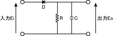
- FIG. 10 is a circuit diagram showing a configuration of an envelope detector in the Fourier transform spectrometer of the second embodiment.
- the Fourier transform spectrometer Db Similar to the Fourier transform spectrometer Da according to the first embodiment, the Fourier transform spectrometer Db according to the second embodiment measures the measured light to be measured with an interferometer, and integrates the measured measured light. This is a device for obtaining a spectrum of measured light by Fourier transforming an interferogram.
- the extraction unit 4111a when the extraction unit 4111a extracts the output of the predetermined range i from the output of the interferometer 11, the extraction unit 4111a extracts this according to the amplitude information of the vibration in the movable mirror 115.
- the Fourier transform spectrometer Db in the second embodiment further includes a center burst position detection unit that detects the position of the center burst in the interferogram, and the extraction unit 4111b includes the interferometer 11.
- the predetermined range i to be taken out is set using the center burst position detected by the center burst position detection unit as the amplitude information of the vibration in the movable mirror 115, and the interferometer 11.
- the output of the set predetermined range i is extracted from the output of.
- the Fourier transform spectrometer Db in the second embodiment includes an interferometer 11, a light receiving processing unit 20, a position detection processing unit 30b, a control calculation unit 41b, and an input.
- a unit 42 and an output unit 43 are provided.
- the interferometer 11, the light receiving processing unit 20, the input unit 42, and the output unit 43 in the Fourier transform spectrometer Db of the second embodiment are respectively connected to the interferometer 11 in the Fourier transform spectrometer Da of the first embodiment. Since it is the same as that of the light reception processing unit 20, the input unit 42, and the output unit 43, description thereof is omitted.
- the position detection processing unit 30b includes, for example, a position measurement light source 31b, a second light receiving unit 36, a zero-cross detection unit 37, and an envelope detection unit 38.
- the position detection processing unit 30b obtains the interference light of the laser light emitted from the position measurement light source 31b with the interferometer 11, as described with reference to FIG. 2 in the first embodiment.
- 32, a beam splitter 33, a beam splitter 34, and a condenser lens 35 are further provided. That is, the Fourier transform spectrometer Db of the second embodiment is provided with a position measurement light source 31b instead of the position measurement light source 31a with respect to the Fourier transform spectrometer Da of the first embodiment, and further includes an envelope detector. 38.
- the second light receiving unit 36, the zero cross detection unit 37, the collimator lens 32, the beam splitter 33, the beam splitter 34, and the condenser lens 35 in the Fourier transform spectrometer Db of the second embodiment are respectively the first embodiment. Since this is the same as the second light receiving unit 36, the zero cross detection unit 37, the collimator lens 32, the beam splitter 33, the beam splitter 34, and the condensing lens 35 in the Fourier transform spectrometer Da, the description thereof is omitted.
- the position measurement light source 31b is a light source device that emits laser light having a predetermined line width set in advance.
- the position measuring light source 31b includes, for example, a semiconductor laser that emits laser light having a predetermined line width. Further, for example, the position measuring light source 31b includes a laser device that emits monochromatic laser light, and a high-frequency superimposing device that superimposes the monochromatic laser light emitted from the laser device at a high frequency. A laser beam having a predetermined line width is emitted.
- the predetermined line width is a wavelength width (frequency width) such that the amplitude of the laser light obtained by the interferometer 11 changes in accordance with the movement of the movable mirror 115 of the interferometer 11. ).
- the magnitude of the amplitude of the laser beam in the interference light depends on the movement of the movable mirror 115 of the interferometer 11 as shown in FIG. 4 used in the description of the first embodiment. It does not change.
- Laser light having such a predetermined line width, and an example, as shown in FIG. 8, Gaussian profile relative to the central wave number 15151.52Cm -1 is a half-value width (FWHM) 2.3 cm -1 have.
- the laser light emitted from the position measuring light source 31 b is incident on the interferometer 11, and the interference light of the laser light is received by the second light receiving unit 36.
- the second light receiving unit 36 outputs an electrical signal corresponding to the light intensity of the interference light of the laser light to each of the zero cross detection unit 37 and the envelope detection unit 38.
- the envelope detector 38 is a circuit that detects an envelope of an electric signal input from the second light receiver 36 and corresponding to the light intensity of the interference light of the laser beam.
- the envelope detector 38 can employ various circuit configurations. For example, as shown in FIG. 10, the envelope detector 38 is connected in series with the diode D by being connected to the diode D and the cathode terminal of the diode D.
- the resistor element R is connected to the resistor element R, and the capacitor C is connected in parallel to the resistor element R. Both ends of the series-connected diode D and the resistor element R are input ends, and both ends of the resistor element R are The output end.
- the envelope detector 38 can detect the envelope with such a simple circuit configuration.
- the envelope detection unit 38 outputs an envelope of an electric signal corresponding to the detected light intensity of the interference light of the laser beam to the control calculation unit 41b.
- the control calculation unit 41b controls each part of the Fourier transform spectrometer Db according to the function of each part in order to obtain the spectrum of the light to be measured.
- the control calculation unit 41b functionally includes a spectrum calculation unit 411b and a center burst position calculation unit 412 by executing a program.
- the center burst position calculation unit 412 detects the position of the center burst in the interferogram. More specifically, in this embodiment, the center burst position calculation unit 412 detects a position that gives the maximum value of the envelope detected by the envelope detection unit 38 as the position of the center burst. As described above, in the present embodiment, the position of the center burst detects the envelope of the light intensity in the interference light of the laser light obtained by making the laser light having a predetermined line width enter the interferometer 11, It is obtained by detecting the position giving the maximum value of the detected envelope.
- the spectrum calculation unit 411b obtains the spectrum of the light to be measured by Fourier-transforming an integrated interferogram obtained by integrating a plurality of interferograms of the light to be measured generated by the interferometer 11. is there.
- the spectrum calculation unit 411b is functionally configured with an extraction unit 4111b, a search unit 4112, an integration unit 4113, and a calculation unit 4114 by executing a program. That is, the spectrum calculation unit 411b in the Fourier transform spectrometer Db of the second embodiment is different from the spectrum calculation unit 411a in the Fourier transform spectrometer Da of the first embodiment in that the extraction unit 4111b functions instead of the extraction unit 4111a. Constructed.
- the search unit 4112, the integration unit 4113, and the calculation unit 4114 of the spectrum calculation unit 411b in the Fourier transform spectrometer Db of the second embodiment are respectively the spectrum calculation unit 411b of the Fourier transform spectrometer Da of the first embodiment. Since the search unit 4112, the integration unit 4113, and the calculation unit 4114 are the same as those of the search unit 4112 of FIG.
- the extraction unit 4111 b When the output of the predetermined range i is extracted from the output of the interferometer 11, the extraction unit 4111 b performs center burst as amplitude information at the time of the reciprocation in the optical path difference forming optical element, in this embodiment, as vibration amplitude information in the movable mirror 115.
- the predetermined range i to be extracted is set using the position of the center burst detected by the position calculation unit 412, and the output of the set predetermined range i is extracted from the output of the interferometer 11.
- the extraction unit 4111 b extracts the predetermined range extracted this time with respect to the predetermined range extracted in the first measurement.
- the predetermined range i to be extracted this time is set by matching the center position of the predetermined range i with the position of the center burst obtained by the center burst position calculation unit 412, and this setting is made from the output of the interferometer 11.
- the output of the predetermined range i is taken out.
- FIG. 11 is a diagram (No. 1) for describing a predetermined range to be taken out by the takeout unit in the second embodiment.
- FIG. 12 is a diagram (No. 2) for explaining a predetermined range to be taken out by the take-out unit in the second embodiment.
- FIGS. 11A and 12A show measurement results (outputs of the AD conversion unit 23) in the first measurement and the n-th measurement (n is an integer of 2 or more), respectively
- FIG. FIG. 12B and FIG. 12B show envelopes (outputs of the envelope detector 38) in the first and n-th measurements (n is an integer of 2 or more), respectively.
- the Fourier transform spectrometer Db takes in the measurement light emitted from the measurement object SM.
- the measured light is incident on the interferometer 11b and is received by the first light receiving unit 21 as interference light of the measured light, as in the case of the interferometer 11 of the Fourier transform spectrometer Da of the first embodiment.
- the electric signal is amplified by the amplification unit 22 and output to the AD conversion unit 23.
- the Fourier transform spectrometer Db also captures laser light having a predetermined half width emitted from the position measuring light source 31b.
- This laser light is incident on the interferometer 11b through the beam splitter 33, interferes with the interferometer 11b in the same manner as described above, and is received by the second light receiving unit 36 through the beam splitter 34 as interference light of the laser light. Is done.
- the second light receiving unit 36 photoelectrically converts the incident interference light of the laser beam and outputs the output electric signal to the zero cross detection unit 37 and the envelope detection unit 38, respectively.
- the zero cross detector 37 detects the zero cross timing of the electrical signal and outputs it to the AD converter 23. While such measured light and laser light are respectively taken into the interferometer 11b, the movable mirror 115 of the interferometer 11b is moved along the optical axis direction under the control of the control calculation unit 41b.
- the AD conversion unit 23 samples the electric signal from the amplification unit 22 at the zero cross timing from the zero cross detection unit 37 and performs AD conversion from an analog signal to a digital signal.
- the AD conversion unit 23 controls the electric signal of the AD converted digital signal. It outputs to the spectrum calculating part 411b of the calculating part 41b.
- an interferogram as shown in FIGS. 11A and 12A is input from the AD conversion unit 23 to the spectrum calculation unit 411b of the control calculation unit 41b.
- the envelope detection unit 38 an electric signal (output of the second light receiving unit 36) based on the interference light of the laser beam having the predetermined line width is subjected to envelope detection, and FIG. 11 (B) and FIG. ) Is input from the envelope detector 38 to the center burst position calculator 412 of the control calculator 41b.
- the envelope of the light intensity in the interference light of the laser light having the predetermined line width is the same as in the case of the monochromatic laser light in the zero cross timing, but the amplitude is the largest at the position of the optical path difference 0, and the sideband It has a profile in which the amplitude gradually decreases as it approaches the position.
- the envelope of the light intensity reaches a maximum value at the center burst position. Therefore, the position of the center burst can be detected by detecting the envelope of the light intensity in the interference light of the laser light having a predetermined line width.
- the center burst position calculation unit 412 detects the maximum value of the envelope input from the envelope detection unit 38, and obtains the position giving this maximum value as the position of the center burst. Then, the center burst position calculation unit 412 outputs the obtained center burst position to the extraction unit 4111b.
- the interferogram of the light to be measured is input from the AD conversion unit 23 and the position of the center burst is input from the center burst position calculation unit 412 to the extraction unit 4111b.
- the extraction unit 4111b is center information as amplitude information when the optical path difference forming optical element is reciprocated, that is, amplitude information of vibration in the movable mirror 115 in this embodiment.
- the predetermined range i to be extracted is set using the position of the center burst detected by the burst position calculation unit 412, and the output of the set predetermined range i is extracted from the output of the interferometer 11.
- the extraction unit 4111b extracts the output of the predetermined range i from the output of the interferometer 11, while expanding the predetermined range i extracted this time with respect to the predetermined range extracted in the first measurement, A predetermined range i is set around the center burst position, and the output of the set predetermined range i is extracted from the output of the interferometer 11.
- the predetermined range i is expressed by Equation 12 (see FIGS. 11A and 11B), and the nth time In the measurement, the predetermined range i is expressed by the following expression 13 (see FIGS. 12A and 12B).
- the search unit 4112 finds measurement data having the same optical path difference in each measurement data set extracted by the extraction unit 4111b. For example, as in the first embodiment, the search unit 4112 obtains the maximum value of the cross-correlation, obtains the minimum value in the sum of the squares of the differences about the measurement points, or about the measurement points. The measurement data of the same optical path difference is found by obtaining the minimum value in the sum of the absolute values of the differences.
- the following equation 14 when obtaining the maximum value of the cross-correlation, the following equation 14 is used, and when obtaining the minimum value in the sum of the squares of the differences for the measurement points, the following equation 15 is obtained.
- the minimum value in the sum of the absolute values of the differences for the measurement point is used, the following equation 16 is used.
- the width of the range from which data is extracted (the width from the start position to the end position of the extraction range) is widened or narrowed according to the position I (n) that gives the maximum value of the envelope. It may be changed by doing. For example, when I (n) ⁇ I (1), in the n-th measurement data set Interferogram n (i), the number of points represented by the following expression 17-2 in the range represented by the following expression 17-1 When data is extracted and I (n) ⁇ I (1), in the nth measurement data set Interferogram n (i), it is expressed by the following expression 17-4 in the range expressed by the following expression 17-3. Data is retrieved.
- the integration unit 4113 uses the same optical path found by the search unit 4112 in each measurement data set extracted by the extraction unit 4111b.
- An integrated interferogram is generated by adding the difference measurement data together.
- the calculation unit 4114 obtains the spectrum of the light to be measured by Fourier transforming the generated integrated interferogram according to the above formulas 9 and 10. The obtained spectrum of the light to be measured is output to the output unit 43.
- the position of the center burst is detected by the envelope detector 38 and the center burst position calculator 412.
- this detected center burst is used as amplitude information at the time of the reciprocation in the optical path difference forming optical element, that is, vibration amplitude information in the movable mirror 115 in this embodiment.
- the predetermined range i to be taken out is set according to the detected center burst position.
- the position of the center burst varies due to the amplitude variation, but the position of the center burst is actually detected and the predetermined range i is set. Therefore, measurement data in a range including the center burst can be surely taken out, and accordingly, a plurality of interferograms can be integrated more suitably.
- the Fourier transform spectrometer Db of the second embodiment detects the position of the center burst by detecting the envelope of the light intensity in the interference light of the laser light having a predetermined line width, for example, FIG.
- the detector circuit can be configured with a simpler circuit configuration as shown in FIG.
- the Fourier transform spectrometer Db of the second embodiment is configured such that the laser beam is a laser beam having a predetermined line width, and detects the position of the movable mirror 115 as a configuration for detecting the position of the center burst. A part of the structure is diverted. More specifically, the configuration from the position measurement light source 31 b to the second light receiving unit 36 is shared, and the output of the second light receiving unit 36 is output to each of the zero cross detection unit 37 and the envelope detection unit 38. For this reason, the Fourier transform spectrometer Db of the second embodiment can detect the position of the center burst with a smaller circuit configuration.
- the position measurement light source 31b a laser device that emits laser light having a predetermined line width by superimposing monochromatic laser light at high frequency, or a predetermined line A semiconductor laser that emits laser light having a width is used. For this reason, in the second embodiment, a position measurement light source 31b that emits laser light having the predetermined line width can be configured more simply.
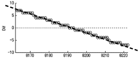
- FIG. 13 is a diagram for explaining a second mode method for obtaining the position of the center burst based on the envelope in the interference light of the laser beam.
- FIG. 13A shows the envelope
- FIG. 13B shows a differential waveform of the envelope.
- FIG. 14 is a diagram for explaining the method of the third aspect for obtaining the position of the center burst based on the envelope in the interference light of the laser light.
- the horizontal axis of FIGS. 13 and 14 indicates the optical path difference (position of the moving mirror 115), and these vertical axes indicate the levels.
- the center burst position calculation unit 412 calculates the maximum value of the envelope input from the envelope detection unit 38 according to the movement of the movable mirror 115 (change in optical path difference).
- the detection may be performed at a point where the amplitude value (level) has changed from increase to decrease.
- FIG. 13A when the envelope is in the vicinity of the maximum value, the movement of the movable mirror 115 (optical path difference). If the point changes relatively slowly according to the change of the above, it is not easy to detect the point with high accuracy.
- the center burst position calculation unit 412 determines the position that gives the maximum value of the envelope detected by the envelope detection unit 38 based on the difference information of the envelope detected by the envelope detection unit 38 as the position of the center burst. You may detect as.
- the center burst position calculation unit 412 obtains a difference between two points on the envelope at an appropriate interval. For example, when the difference between two points on the envelope is obtained with respect to the envelope shown in FIG. 13A, the difference graph shown in FIG. 13B is obtained as the difference information. In the difference graph, since the zero cross point at which the difference value changes from a positive value to a negative value corresponds to the position where the maximum value is given, the center burst position calculation unit 412 determines that the difference value is from the positive value in the difference graph. A zero cross point that turns to a negative value is obtained, and the zero cross point may be set as the center burst position.
- the larger the interval for obtaining the difference the larger the difference value, and the zero cross point can be detected with higher accuracy.
- the position of the center burst can be detected with higher accuracy.
- the storage capacity of the storage element that stores the measurement result of the envelope is restricted, and the interval cannot be made too large, or the number of bits Z of the AD conversion unit 23 is small and the resolution is small.
- the difference may have a stepped shape near the zero cross point as shown in FIG. In such a case, the position of the center burst may be obtained by linearly approximating the difference graph near the zero cross point by the least square method and obtaining the zero cross point of the approximate straight line.
- the center burst position calculation unit 412 in the Fourier transform spectrometer Db of the second embodiment can more accurately detect the position that gives the maximum value of the envelope. Even if it is difficult to distinguish the maximum value of the envelope because the change of the envelope is gentle, it is possible to detect the position where the maximum value of the envelope is given.
- a Fourier transform spectrometer includes a plurality of optical elements that receive measurement light to be measured and form two optical paths between an incident position of the measurement light and an interference position,
- the plurality of optical elements include an interferometer including an optical path difference forming optical element that causes an optical path difference between the two optical paths by moving in the optical axis direction, and the light to be measured generated by the interferometer.
- a spectrum calculation unit that obtains a spectrum of the measured light by performing a Fourier transform on an integrated interferogram obtained by integrating a plurality of interferograms of the optical path difference forming optical element, In order to generate a plurality of interferograms of the interferogram, reciprocates twice or more in the optical axis direction, and the spectrum calculation unit takes out a predetermined range of output from the output of the interferometer A predetermined range to be extracted is set according to amplitude information at the time of the reciprocation in the optical path difference forming optical element, and an extraction unit for extracting the output of the predetermined range from the output of the interferometer; In order to integrate a plurality of interferograms, a search unit for finding measurement data of the same optical path difference at each output in each predetermined range extracted by the extraction unit, and a plurality of interferograms of the measured light Therefore, in each output of each predetermined range extracted by the extraction unit, an integration unit that generates the integrated interferogram by adding together measurement data of the same optical path difference found
- the Fourier transform spectroscopic method includes a plurality of optical elements that receive light to be measured to be measured and form two optical paths between an incident position of the light to be measured and an interference position.
- the plurality of optical elements includes an optical path difference forming optical element that generates an optical path difference between the two optical paths by moving in the optical axis direction, and the interferometer generated by the interferometer
- a spectrum calculation unit that obtains a spectrum of the measured light by Fourier transforming an integrated interferogram obtained by integrating a plurality of interferograms of the measured light, and the optical path difference forming optical element comprises: In order to generate a plurality of interferograms of the light to be measured, a Fourier transform spectroscopic method used in a Fourier transform spectrometer that reciprocates twice or more in the optical axis direction.
- the predetermined range to be extracted according to the amplitude information at the time of the reciprocation in the optical path difference forming optical element is An extraction step of setting and extracting the output of the set predetermined range from the output of the interferometer, and each of the predetermined ranges extracted in the extraction step to integrate a plurality of interferograms of the measured light
- the product is the integrated interferogram was and a calculation step of obtaining a spectrum of the light to be measured by Fourier transform.
- the predetermined range to be extracted is the amplitude when the optical path difference forming optical element is reciprocated.
- the Fourier transform spectrometer and the Fourier transform spectroscopic method having such a configuration since amplitude information at the time of reciprocation in the optical path difference forming optical element is taken into account, measurement data in a range including an interferogram is more obtained. Therefore, it is possible to appropriately extract a plurality of interferograms.
- the amplitude information used in the extraction unit is obtained by calculating the center position of the reciprocation in the first measurement and the center position of the reciprocation in the current measurement. This is the amount of deviation.
- the Fourier transform spectrometer having such a configuration a deviation amount between the reciprocal center position in the first measurement and the reciprocal center position in the current measurement is used as the amplitude information. For this reason, the Fourier transform spectrometer having such a configuration can suitably cope with a case where the optical path difference forming optical element is shifted left-right symmetrically, and more appropriately extracts measurement data in a range including the interferogram. Therefore, a plurality of interferograms can be preferably integrated.
- the Fourier transform spectrometer described above further includes a center burst position detection unit that detects a position of the center burst in the interferogram, and the extraction unit has a predetermined range from the output of the interferometer.
- the predetermined range to be taken out is set using the position of the center burst detected by the center burst position detecting unit as amplitude information at the time of the reciprocation in the optical path difference forming optical element, and the interferometer The output of the set predetermined range is taken out from the output.
- the Fourier transform spectrometer having such a configuration In the Fourier transform spectrometer having such a configuration, the position of the center burst is detected by the center burst position detector. For this reason, the Fourier transform spectrometer having such a configuration can reliably extract measurement data in a range including the center burst, and can more preferably integrate a plurality of interferograms.
- the center burst position detection unit may interfere with the laser light obtained by causing laser light having a predetermined line width to enter the interferometer. An envelope of light intensity in the light is detected, and a position giving the maximum value of the detected envelope is detected as the position of the center burst.
- the Fourier transform spectrometer Since the Fourier transform spectrometer having such a configuration detects the position of the center burst by detecting the envelope of the light intensity in the interference light of the laser beam having a predetermined line width, it has a simpler circuit configuration.
- a detection circuit can be configured.
- the interference light of the laser beam is used to detect the position of the movable mirror, and the zero cross timing in the interference light of the laser beam is set as the sampling timing.
- a part of the configuration for detecting the position of the movable mirror is obtained by using the laser beam as the laser beam having the predetermined line width of the position measurement light source. It can also be used as a part of the configuration for detecting the position of the center burst. For this reason, the Fourier transform spectrometer having the above configuration can detect the position of the center burst with a smaller circuit configuration.
- the position measurement light source is a laser device that emits laser light having the predetermined line width by superimposing monochromatic laser light at high frequency.
- a position measurement light source that emits laser light having the predetermined line width is configured more simply.
- the position measurement light source is a semiconductor laser that emits laser light having the predetermined line width.
- a position measurement light source that emits laser light having the predetermined line width is configured more simply.
- the center burst position detection unit is detected by the envelope detection unit based on difference information of the envelope detected by the envelope detection unit. A position that gives the maximum value of the envelope is detected as the position of the center burst.
- the Fourier transform spectrometer having such a configuration can detect the position where the maximum value of the envelope is given more accurately, and since the change of the envelope is gentle, the maximum value of the envelope is Even if it is difficult to distinguish, it is possible to detect the position that gives the maximum value of the envelope.
- the search unit outputs a predetermined range of outputs extracted by the extraction unit in the first measurement and the nth (n is an integer of 2 or more). In this measurement, the maximum value of the cross-correlation is obtained with respect to the output within the predetermined range extracted by the extraction unit, and measurement data having the same optical path difference is found.
- the Fourier transform spectrometer having such a configuration can preferably integrate a plurality of interferograms.
- the search unit outputs a predetermined range of outputs extracted by the extraction unit in the first measurement and the nth (n is an integer of 2 or more).
- the measurement data of the same optical path difference is found by obtaining the minimum value in the sum of the squares of the differences at the measurement points with respect to the output in the predetermined range taken out by the take-out unit in the above measurement.
- the Fourier transform spectrometer having such a configuration can preferably integrate a plurality of interferograms.
- the search unit outputs a predetermined range of outputs extracted by the extraction unit in the first measurement and the nth (n is an integer of 2 or more).
- the measurement data of the same optical path difference is found by obtaining the minimum value in the sum of the absolute values of the differences at the measurement points with respect to the output in the predetermined range extracted by the extraction unit in the measurement.
- the measurement data of the same optical path difference is found by the sum of the absolute values of the differences. Therefore, the measurement data of the same optical path difference can be found by simpler information processing.
- a Fourier transform spectrometer and a Fourier transform spectrometer can be provided.
Abstract
This Fourier transform spectrometer (Da) is provided with an interferometer (11) which produces an optical path difference between two optical paths using vibration, and a spectrum calculation unit (411a) which finds the spectrum of light to be measured by Fourier-transforming a cumulative interferogram obtained by adding up a plurality of interferograms generated in the interferometer (11). When extracting a predetermined range of output from the output of the interferometer (11), the spectrum calculation unit (411a) sets the predetermined range according to amplitude information relating to the vibration and extracts the predetermined range of output from the output of the interferometer (11).
Description
本発明は、フーリエ変換型分光計およびフーリエ変換型分光方法に関し、特に、複数のインターフェログラムを積算して、被測定光のスペクトルを求めるために用いられるインターフェログラムを生成する場合に、好適に複数のインターフェログラムを積算することができるフーリエ変換型分光計およびフーリエ変換型分光方法に関する。
The present invention relates to a Fourier transform spectrometer and a Fourier transform spectroscopic method, and is particularly suitable for generating an interferogram used to obtain a spectrum of measured light by integrating a plurality of interferograms. The present invention relates to a Fourier transform spectrometer and a Fourier transform spectroscopic method capable of integrating a plurality of interferograms.
分光計は、測定対象の被測定光のスペクトルを測定する装置であり、その1つに干渉計で被測定光の干渉光を測定し、この測定結果をフーリエ変換することによって被測定光のスペクトルを求めるフーリエ変換型分光計がある。
The spectrometer is a device that measures the spectrum of the light to be measured, one of which is an interferometer that measures the interference light of the light to be measured, and Fourier transforms the measurement result to obtain the spectrum of the light to be measured. There is a Fourier transform spectrometer that calculates
このフーリエ変換型分光計では、前記干渉計の出力は、前記被測定光に含まれる複数の波長の光が前記干渉計によって一括で干渉された合成波形であり、一般に、インターフェログラムと呼ばれる。そして、フーリエ変換型分光計では、このインターフェログラムがフーリエ変換されることによって、被測定光のスペクトルが求められる。このインターフェログラムは、所定の範囲で1または複数の急峻なピークを持つと共に残余の範囲では略ゼロレベルとなるプロファイルとなり、この1または複数の急峻なピークのうちの中央のピークは、センターバーストと呼ばれる。
In this Fourier transform spectrometer, the output of the interferometer is a composite waveform in which light of a plurality of wavelengths included in the light to be measured is collectively interfered by the interferometer, and is generally called an interferogram. In the Fourier transform spectrometer, the spectrum of the light to be measured is obtained by Fourier transforming the interferogram. This interferogram has a profile that has one or a plurality of steep peaks in a predetermined range and a substantially zero level in the remaining range, and the center peak of the one or more steep peaks has a center burst. Called.
そして、フーリエ変換型分光計では、1回の測定で得られたインターフェログラムをフーリエ変換することによって被測定光のスペクトルを求めると、通常、SN比が悪く、良好な精度の結果が得られ難い。このため、フーリエ変換型分光計では、1個の測定対象に対しインターフェログラムが複数回測定され、これら複数のインターフェログラムが積算されることによって、被測定光のスペクトルを求めるために用いられるインターフェログラム(以下、「積算インターフェログラム」と呼称する。)が生成される。これら複数回の測定は、通常、干渉計の2つの光路のうちの一方の光路の光路長を連続的に変化させながら行われる。
In a Fourier transform spectrometer, when the spectrum of the light to be measured is obtained by Fourier transforming the interferogram obtained in one measurement, the signal-to-noise ratio is usually poor and results with good accuracy can be obtained. hard. For this reason, in a Fourier transform spectrometer, an interferogram is measured a plurality of times for one measurement object, and the plurality of interferograms are integrated to obtain a spectrum of light to be measured. An interferogram (hereinafter referred to as “integrated interferogram”) is generated. These measurements are usually performed while continuously changing the optical path length of one of the two optical paths of the interferometer.
このような複数のインターフェログラムを積算する技術は、例えば、特許文献1および特許文献2に開示されている。この特許文献1に開示のインターフェログラム積算装置は、一走査の干渉光を被測定物に照射して得られる単位インターフェログラムを複数積算するインターフェログラム積算装置であって、前記単位インターフェログラムを一時的に記憶する単位インターフェログラム記憶手段と、前記単位インターフェログラム記憶手段に記憶された単位インターフェログラムデータよりセンターバースト位置を検出する最大位置検出手段と、前記最大位置検出手段により検出された単位インターフェログラムのセンターバースト位置を基準として、該単位インターフェログラムの位置軸上で両側にそれぞれ予め定められた所定量ずつ切り取り、切取インターフェログラムを採取する切取手段と、複数の単位インターフェログラムに対応して順次得られる複数の切取インターフェログラムを積算する積算手段とを備えている。
A technique for integrating such a plurality of interferograms is disclosed in, for example, Patent Document 1 and Patent Document 2. The interferogram integrating device disclosed in Patent Document 1 is an interferogram integrating device that integrates a plurality of unit interferograms obtained by irradiating an object to be measured with one scan of interference light, the unit interferogram. A unit interferogram storage means for temporarily storing a gram, a maximum position detection means for detecting a center burst position from unit interferogram data stored in the unit interferogram storage means, and a maximum position detection means With reference to the center burst position of the detected unit interferogram, the unit interferogram is cut in predetermined amounts on both sides on the position axis of the unit interferogram, and a cutting means for collecting the cut interferogram, and a plurality of cutting means Obtained sequentially corresponding to the unit interferogram And a integrator for integrating the cut interferogram number.
また、前記特許文献2では、測定光が被測定対象を透過して生じる測定光インターフェログラムと、参照光が前記被測定対象を迂回して生じる参照光インターフェログラムとが同期して測定され、基準波形記憶部に予め記憶されている、基準となる参照光インターフェログラムに対して、今回の測定周期における当該参照光インターフェログラムの位相が最も一致する位相差が演算され、この演算された位相差を基準に同期加算することで、測定光インターフェログラムと参照光インターフェログラムの平均が求められる。
In Patent Document 2, a measurement light interferogram generated when measurement light passes through the measurement target and a reference light interferogram generated by bypassing the measurement target are measured in synchronization with each other. The phase difference that most closely matches the phase of the reference light interferogram in the current measurement cycle is calculated with respect to the reference light interferogram that is stored in advance in the reference waveform storage unit. The average of the measurement light interferogram and the reference light interferogram is obtained by synchronously adding based on the obtained phase difference.
このような複数のインターフェログラムを積算する場合では、各インターフェログラム間において、同じ光路差の測定データ同士を足し合わせる必要がある。このため、まず、1回の測定で得られた複数の測定データ(各サンプリング点での測定データ)の中から、センターバーストを含む範囲の測定データが取り出され、次に、同じ光路差の測定データが見つけ出され、その後に、同じ光路差の測定データ同士が足し合わされる。
When integrating a plurality of such interferograms, it is necessary to add together measurement data having the same optical path difference between the interferograms. For this reason, first, measurement data in a range including the center burst is extracted from a plurality of measurement data (measurement data at each sampling point) obtained by one measurement, and then the measurement of the same optical path difference is performed. Data is found, and then the measured data with the same optical path difference are added together.
ところで、干渉計の光路長を変更するために、例えば共振振動によって反射面を該反射面に垂直な方向に移動させる光反射機構が用いられる場合では、ノイズ、例えば外部の振動等が混入すると、このノイズ(外部の振動等)の影響によって反射面の振幅が変動してしまう。このため、複数回の測定に対して同じ範囲で測定データが取り出された場合、この取り出された範囲の測定データの中にセンターバーストが含まれないケースが生じる場合がある。この結果、インターフェログラムの位置合わせができなくなり、各光路差全体に亘って複数のインターフェログラムを積算することができなくなってしまう。
By the way, in order to change the optical path length of the interferometer, for example, when a light reflecting mechanism that moves the reflecting surface in a direction perpendicular to the reflecting surface by resonant vibration is used, when noise such as external vibration is mixed, The amplitude of the reflecting surface fluctuates due to the influence of this noise (external vibration or the like). For this reason, when measurement data is extracted in the same range for a plurality of measurements, there may be a case where the center burst is not included in the measurement data in the extracted range. As a result, the interferograms cannot be aligned, and a plurality of interferograms cannot be integrated over the entire optical path difference.
本発明は、上述の事情に鑑みて為された発明であり、その目的は、インターフェログラムを含む範囲の測定データをより適切に取り出すことによって好適に複数のインターフェログラムを積算することができるフーリエ変換型分光計およびフーリエ変換型分光方法を提供することである。
The present invention has been made in view of the above-described circumstances, and its object is to suitably integrate a plurality of interferograms by more appropriately extracting measurement data in a range including the interferogram. A Fourier transform type spectrometer and a Fourier transform type spectroscopic method are provided.
本発明にかかるフーリエ変換型分光計およびフーリエ変換型分光方法では、振動を用いることによって2個の光路間に光路差を生じさせる干渉計で生成されたインターフェログラムが複数積算され、これによって得られた積算インターフェログラムをフーリエ変換することによって被測定光のスペクトルが求められる。そして、前記干渉計の出力から所定範囲の出力を取り出す場合に、この取り出す所定範囲は、前記振動の振幅情報に応じて設定される。このため、このような構成のフーリエ変換型分光計およびフーリエ変換型分光方法は、前記振動の振幅情報が参酌されるから、インターフェログラムを含む範囲の測定データをより適切に取り出すことができ、したがって、好適に複数のインターフェログラムを積算することができる。
In the Fourier transform spectrometer and the Fourier transform spectroscopic method according to the present invention, a plurality of interferograms generated by an interferometer that generates an optical path difference between two optical paths by using vibrations are integrated and obtained by this. The spectrum of the light to be measured is obtained by Fourier transforming the obtained integrated interferogram. When a predetermined range of output is extracted from the output of the interferometer, the predetermined range to be extracted is set according to the amplitude information of the vibration. For this reason, the Fourier transform spectrometer and the Fourier transform spectroscopic method having such a configuration can take out the measurement data in a range including the interferogram more appropriately because the amplitude information of the vibration is taken into consideration. Therefore, a plurality of interferograms can be preferably integrated.
上記並びにその他の本発明の目的、特徴及び利点は、以下の詳細な記載と添付図面から明らかになるであろう。
The above and other objects, features and advantages of the present invention will become apparent from the following detailed description and the accompanying drawings.
以下、本発明にかかる実施の一形態を図面に基づいて説明する。なお、各図において同一の符号を付した構成は、同一の構成であることを示し、適宜、その説明を省略する。
Hereinafter, an embodiment according to the present invention will be described with reference to the drawings. In addition, the structure which attached | subjected the same code | symbol in each figure shows that it is the same structure, The description is abbreviate | omitted suitably.
(第1実施形態)
図1は、第1実施形態におけるフーリエ変換型分光計の構成を示すブロック図である。図2は、フーリエ変換型分光計における主に干渉計の構成を示す図である。 (First embodiment)
FIG. 1 is a block diagram showing a configuration of a Fourier transform spectrometer in the first embodiment. FIG. 2 is a diagram mainly showing the configuration of the interferometer in the Fourier transform spectrometer.
第1実施形態にかかるフーリエ変換型分光計Daは、測定対象の被測定光のスペクトルを測定する装置であって、前記被測定光を干渉計で測定し、この測定した被測定光の干渉光の波形(インターフェログラム)をフーリエ変換することによって被測定光のスペクトルを求める装置である。そして、本実施形態のフーリエ変換型分光計Daでは、SN比を改善し、良好な精度の結果を得るために、前記被測定光のスペクトルを求めるためにフーリエ変換される変換対象には、前記干渉計で生成された前記被測定光のインターフェログラムを複数積算することによって得られた積算インターフェログラムが用いられる。このようなフーリエ変換型分光計Daは、例えば、図1および図2に示すように、測定対象物体SMから放射された光(被測定光)が入射され、前記被測定光の干渉光を射出する干渉計11と、干渉計11で得られた被測定光の干渉光を受光して光電変換によって被測定光の干渉光の波形の電気信号(被測定光の干渉光における光強度変化を表す電気信号)を出力する受光処理部20と、干渉計11の移動鏡115の位置を検出する位置検出処理部30aと、制御演算部41aと、入力部42と、出力部43とを備えている。測定対象物体SMは、自発光する光源であってよく、また、他の光源から放射された光が照射され、前記光を反射、透過または再放射(例えば蛍光発光等)することによって光を放射するものであってもよい。
The Fourier transform spectrometer Da according to the first embodiment is an apparatus for measuring the spectrum of the light to be measured as a measurement object, and measures the light to be measured with an interferometer, and the interference light of the measured light to be measured. This is a device for obtaining the spectrum of the light to be measured by Fourier transforming the waveform (interferogram). In the Fourier transform spectrometer Da of the present embodiment, in order to improve the SN ratio and obtain a good accuracy result, the transform target to be Fourier transformed to obtain the spectrum of the light to be measured is An integrated interferogram obtained by integrating a plurality of interferograms of the light to be measured generated by an interferometer is used. For example, as shown in FIGS. 1 and 2, such a Fourier transform spectrometer Da receives light (measurement light) emitted from the measurement target object SM and emits interference light of the measurement light. The interferometer 11 that receives the interference light of the light to be measured obtained by the interferometer 11, and an electric signal of the waveform of the interference light of the light to be measured by photoelectric conversion (represents a change in light intensity in the interference light of the light to be measured) A light reception processing unit 20 that outputs an electrical signal), a position detection processing unit 30a that detects the position of the movable mirror 115 of the interferometer 11, a control calculation unit 41a, an input unit 42, and an output unit 43. . The measurement object SM may be a light source that emits light by itself, and is irradiated with light emitted from another light source, and radiates light by reflecting, transmitting, or re-radiating the light (for example, fluorescence emission). You may do.
干渉計11は、測定対象の被測定光が入射され、この入射された被測定光を2個の第1および第2被測定光に分岐し、これら分岐した第1および第2被測定光のそれぞれを、互いに異なる2個の経路である第1および第2光路のそれぞれに進行(伝播)させ、再び合流させるものであり、この分岐点(分岐位置)から合流点(合流位置、干渉位置)までの間に第1および第2光路間に光路差があると、前記合流の際に位相差が生じているため、前記合流によって干渉縞を生じるものである。干渉計11は、例えばマッハツェンダー干渉計等の種々のタイプの第1および第2光路を備える干渉計を利用することができるが、本実施形態では、図2に示すように、マイケルソン干渉計によって構成されている。
The interferometer 11 receives measurement light to be measured, branches the incident measurement light into two first and second measurement lights, and the branched first and second measurement lights. Each travels (propagates) in the first and second optical paths, which are two different paths, and merges again. From this branch point (branch position), a merge point (merging position, interference position). If there is an optical path difference between the first and second optical paths until then, a phase difference is generated at the time of merging, so that interference fringes are generated by the merging. As the interferometer 11, for example, an interferometer having various types of first and second optical paths such as a Mach-Zehnder interferometer can be used. In this embodiment, as shown in FIG. It is constituted by.
より具体的には、図2に示すように、干渉計11は、複数の光学素子として半透鏡112、固定鏡114、および、光反射面が光軸方向に移動する移動鏡115を備え、固定鏡114と移動鏡115とは、各鏡面の各法線が互いに直交するようにそれぞれ配置され、半透鏡112は、その法線が前記固定鏡114および移動鏡115における各法線の直交点を通り、これら各法線に対し45度の角度で交差するように配置される。この干渉計11において、干渉計11に入射された被測定光は、半透鏡112で2個の第1および第2被測定光に分岐する。この分岐した一方の第1被測定光は、半透鏡112で反射されて固定鏡114に入射する。この第1被測定光は、固定鏡114で反射し、来た光路を逆に辿って再び半透鏡112に戻る。一方、この分岐した他方の第2被測定光は、半透鏡112を通過して移動鏡115に入射する。この第2被測定光は、移動鏡115で反射し、来た光路を逆に辿って再び半透鏡112に戻る。これら固定鏡114で反射された第1被測定光および移動鏡115で反射された第2被測定光は、半透鏡112で互いに合流して干渉する。このような構成のマイケルソン干渉計11では、被測定光は、移動鏡115の鏡面における法線方向に沿って干渉計11へ入射され、被測定光の干渉光は、固定鏡114の鏡面における法線方向に沿って干渉計11から射出される。
More specifically, as shown in FIG. 2, the interferometer 11 includes a semi-transparent mirror 112, a fixed mirror 114, and a movable mirror 115 whose light reflecting surface moves in the optical axis direction as a plurality of optical elements. The mirror 114 and the movable mirror 115 are arranged so that the normals of each mirror surface are orthogonal to each other, and the semi-transparent mirror 112 is an orthogonal point of each normal of the fixed mirror 114 and the movable mirror 115. It is arranged so that each of these normals intersects at an angle of 45 degrees. In the interferometer 11, the light to be measured incident on the interferometer 11 is branched into two first and second light to be measured by the semi-transparent mirror 112. The branched first first measured light is reflected by the semi-transparent mirror 112 and enters the fixed mirror 114. The first light to be measured is reflected by the fixed mirror 114 and returns to the semi-transparent mirror 112 again following the optical path that has come. On the other hand, the other branched second measured light passes through the semi-transparent mirror 112 and enters the movable mirror 115. This second light to be measured is reflected by the movable mirror 115, and reversely follows the optical path that has come to return to the semi-transparent mirror 112 again. The first light to be measured reflected by the fixed mirror 114 and the second light to be measured reflected by the moving mirror 115 are merged with each other by the semi-transparent mirror 112 and interfere with each other. In the Michelson interferometer 11 having such a configuration, the light to be measured is incident on the interferometer 11 along the normal direction on the mirror surface of the movable mirror 115, and the interference light of the light to be measured is reflected on the mirror surface of the fixed mirror 114. The light is emitted from the interferometer 11 along the normal direction.
そして、本実施形態では、干渉計11は、被測定光を半透鏡112で2個の第1および第2被測定光に分岐する場合において、半透鏡112で反射した半透鏡112の反射側に配置される位相補償板CPをさらに備えている。すなわち、本実施形態では、半透鏡112で反射した第1被測定光は、位相補償板CPを介して固定鏡114へ入射され、固定鏡114で反射された第1被測定光は、位相補償板CPを介して再び半透鏡112へ入射される。位相補償板CPは、第1被測定光の半透鏡112の透過回数と第2被測定光の半透鏡112の透過回数の相違から生じる第1被測定光と第2被測定光との位相差を無くして前記位相差を補償するものである。
In this embodiment, the interferometer 11 is arranged on the reflection side of the semi-transparent mirror 112 reflected by the semi-transparent mirror 112 when the light to be measured is branched into two first and second measured light beams by the semi-transparent mirror 112. A phase compensation plate CP is further provided. That is, in this embodiment, the first measured light reflected by the semi-transparent mirror 112 is incident on the fixed mirror 114 via the phase compensation plate CP, and the first measured light reflected by the fixed mirror 114 is phase compensated. The light enters the semi-transparent mirror 112 again through the plate CP. The phase compensation plate CP is a phase difference between the first measured light and the second measured light, which is caused by the difference in the number of times the first measured light is transmitted through the semi-transparent mirror 112 and the number of times the second measured light is transmitted through the semi-transmissive mirror 112. Is used to compensate for the phase difference.
第1被測定光は、このような被測定光の入射位置から、半透鏡112、位相補償板CP、固定鏡114および位相補償板CPをこの順に介して半透鏡112に再び至る第1光路を辿る。第2被測定光は、このような被測定光の入射位置から、半透鏡112および移動鏡115をこの順に介して半透鏡112に再び至る第2光路を辿る。
The first measured light has a first optical path from the incident position of the measured light to the semi-transmissive mirror 112 again through the semi-transparent mirror 112, the phase compensation plate CP, the fixed mirror 114, and the phase compensation plate CP in this order. follow. The second measured light follows a second optical path from the incident position of the measured light to reach the semi-transmissive mirror 112 again through the semi-transmissive mirror 112 and the movable mirror 115 in this order.
また、本実施形態では、移動鏡115には、光路差形成光学素子の一例であり、共振振動を用いることによって2個の第1および第2光路間に光路差を生じさせる光学素子である。移動鏡115は、被測定光のインターフェログラムを複数生成するために、光軸方向に2回以上往復する。このような移動鏡115として、例えば、国際公開WO2010/122879号パンフレットに開示の光反射機構が挙げられる。この光反射機構は、反射面を表面に有する第1移動部と、前記第1移動部を支持する支持部と、前記第1移動部と前記支持部とを前記支持部の上下で片持梁形式で連結する第1の梁および平行移動梁と、前記第1移動部を移動させるための駆動部とを備え、前記第1移動部を前記反射面に垂直な方向に共振振動させるものであり、MEMS(Micro Electro Mechanical Systems)技術によって製造される。
In the present embodiment, the movable mirror 115 is an example of an optical path difference forming optical element, and is an optical element that generates an optical path difference between the two first and second optical paths by using resonance vibration. The movable mirror 115 reciprocates twice or more in the optical axis direction in order to generate a plurality of interferograms of the light to be measured. As such a movable mirror 115, for example, a light reflection mechanism disclosed in International Publication WO2010 / 122879 pamphlet can be cited. The light reflecting mechanism includes a first moving part having a reflecting surface on the surface, a support part that supports the first moving part, and the first moving part and the support part that are cantilevered above and below the support part. A first beam and a parallel beam that are connected in a form; and a drive unit for moving the first moving unit, wherein the first moving unit is resonantly vibrated in a direction perpendicular to the reflecting surface. , Manufactured by MEMS (Micro Electro Mechanical Systems) technology.
さらに、本実施形態では、測定対象物体SMから放射された被測定光を平行光で半透鏡112へ入射させるために、測定対象物体SMと半透鏡112との間の適宜な位置に、入射光学系として例えば両凸のコリメータレンズ111が配置され、半透鏡112で第1および第2被測定光を合流して干渉させることによって生じた被測定光の干渉光を集光して第1受光部21へ入射させるために、半透鏡112と第1受光部21との間の適宜な位置に、射出光学系として例えば両凸の集光レンズ116が配置されている。
Furthermore, in this embodiment, in order to make the light to be measured radiated from the measurement target object SM incident on the semi-transparent mirror 112 as parallel light, the incident optical is placed at an appropriate position between the measurement target object SM and the semi-transparent mirror 112. For example, a biconvex collimator lens 111 is disposed as a system, and the first and second light receiving units collect the interference light of the light to be measured generated by the first and second light beams to be combined and interfered by the semi-transparent mirror 112. For example, a biconvex condensing lens 116 is disposed as an emission optical system at an appropriate position between the semi-transparent mirror 112 and the first light receiving unit 21 in order to enter the lens 21.
図1に戻って、受光処理部20は、例えば、第1受光部21と、増幅部22と、アナログ-ディジタル変換部(以下、「AD変換部」と呼称する。)23とを備えている。第1受光部21は、干渉計11で得られた被測定光の干渉光を受光して光電変換することによって、被測定光の干渉光の光強度に応じた電気信号を出力する回路である。第1受光部21は、例えばInGaAsフォトダイオードおよびその周辺回路を備えて構成される赤外線センサ等である。増幅部22は、第1受光部21の出力を予め設定された所定の増幅率で増幅する増幅器である。AD変換部23は、増幅部22の出力をアナログ信号からディジタル信号へ変換(AD変換)する回路である。このAD変換のタイミング(サンプリングタイミング)は、後述のゼロクロス検出部37から入力されたゼロクロスタイミングで実行される。
Returning to FIG. 1, the light reception processing unit 20 includes, for example, a first light reception unit 21, an amplification unit 22, and an analog-digital conversion unit (hereinafter referred to as “AD conversion unit”) 23. . The first light receiving unit 21 is a circuit that outputs an electric signal corresponding to the light intensity of the interference light of the light to be measured by receiving and photoelectrically converting the interference light of the light to be measured obtained by the interferometer 11. . The first light receiving unit 21 is, for example, an infrared sensor that includes an InGaAs photodiode and its peripheral circuits. The amplifying unit 22 is an amplifier that amplifies the output of the first light receiving unit 21 with a predetermined amplification factor set in advance. The AD conversion unit 23 is a circuit that converts the output of the amplification unit 22 from an analog signal to a digital signal (AD conversion). The AD conversion timing (sampling timing) is executed at the zero cross timing input from the zero cross detector 37 described later.
また、位置検出処理部30aは、例えば、位置測定用光源31aと、第2受光部36と、ゼロクロス検出部37とを備えている。そして、位置検出処理部30aは、この位置測定用光源31aから放射されたレーザ光の干渉光を干渉計11で得るために、図2に示すように、コリメータレンズ32と、ビームスプリッター33と、ビームスプリッター34と、集光レンズ35とをさらに備えている。
Further, the position detection processing unit 30a includes, for example, a position measurement light source 31a, a second light receiving unit 36, and a zero cross detection unit 37. Then, the position detection processing unit 30a obtains the interference light of the laser light emitted from the position measuring light source 31a with the interferometer 11, as shown in FIG. 2, a collimator lens 32, a beam splitter 33, A beam splitter 34 and a condenser lens 35 are further provided.
位置測定用光源31aは、単色レーザ光を放射する光源装置である。図2において、コリメータレンズ32およびビームスプリッター33は、位置測定用光源31aから放射されたレーザ光を平行光で干渉計11へ入射させるための入射光学系である。ビームスプリッター33は、その法線が移動鏡115の法線(光軸)に対し45度で交差するように、コリメータレンズ111と半透鏡112との間に配置される。コリメータレンズ32は、例えば両凸のレンズであり、このように配置されたビームスプリッター33に対し45度の入射角で位置測定用光源31aから放射されたレーザ光が入射されるように、適宜な位置に配置される。そして、ビームスプリッター34および集光レンズ35は、干渉計11で生じた前記レーザ光の干渉光を干渉計11から取り出すための射出光学系である。ビームスプリッター34は、その法線が固定鏡114の法線(光軸)に対し45度で交差するように、半透鏡112と集光レンズ116との間に配置される。集光レンズ35は、例えば両凸のレンズであり、このように配置されたビームスプリッター34において45度の射出角で射出されるレーザ光の干渉光を集光して第2受光部36へ入射させる。なお、ビームスプリッター33は、レーザ光を反射するとともに被測定光を透過するダイクロイックミラーである。ビームスプリッター34は、レーザ光の干渉光を反射するとともに被測定光の干渉光を透過するダイクロイックミラーである。
The position measuring light source 31a is a light source device that emits monochromatic laser light. In FIG. 2, a collimator lens 32 and a beam splitter 33 are incident optical systems for causing the laser light emitted from the position measurement light source 31a to enter the interferometer 11 as parallel light. The beam splitter 33 is disposed between the collimator lens 111 and the semi-transparent mirror 112 so that the normal line intersects the normal line (optical axis) of the movable mirror 115 at 45 degrees. The collimator lens 32 is, for example, a biconvex lens, and is appropriately set so that the laser beam emitted from the position measurement light source 31a is incident on the beam splitter 33 arranged in this manner at an incident angle of 45 degrees. Placed in position. The beam splitter 34 and the condenser lens 35 are an emission optical system for taking out the interference light of the laser beam generated by the interferometer 11 from the interferometer 11. The beam splitter 34 is disposed between the semi-transparent mirror 112 and the condenser lens 116 so that the normal line intersects the normal line (optical axis) of the fixed mirror 114 at 45 degrees. The condensing lens 35 is, for example, a biconvex lens, and condenses the interference light of the laser light emitted at an emission angle of 45 degrees in the beam splitter 34 arranged in this manner and enters the second light receiving unit 36. Let The beam splitter 33 is a dichroic mirror that reflects laser light and transmits measured light. The beam splitter 34 is a dichroic mirror that reflects the interference light of the laser light and transmits the interference light of the light to be measured.
このようにコリメータレンズ32、ビームスプリッター33、34および集光レンズ35の各光学素子が配置されると、位置測定用光源31aから放射された単色のレーザ光は、コリメータレンズ32で平行光とされ、その光路がビームスプリッター33で約90度曲げられて、干渉計11の光軸(移動鏡115の鏡面における法線方向)に沿って進行するようになる。したがって、このレーザ光は、被測定光と同様に、干渉計11内を進行し、干渉計11でその干渉光を生じさせる。このレーザ光の干渉光は、ビームスプリッター34で約90度曲げられて、干渉計11から外部に取り出され、集光レンズ35で集光されて第2受光部36で受光される。
When the optical elements of the collimator lens 32, the beam splitters 33 and 34, and the condenser lens 35 are arranged in this way, the monochromatic laser light emitted from the position measurement light source 31a is converted into parallel light by the collimator lens 32. The optical path is bent about 90 degrees by the beam splitter 33 and travels along the optical axis of the interferometer 11 (normal direction on the mirror surface of the movable mirror 115). Therefore, this laser light travels in the interferometer 11 as with the light to be measured, and the interferometer 11 generates the interference light. The interference light of this laser light is bent by about 90 degrees by the beam splitter 34, taken out from the interferometer 11, condensed by the condenser lens 35, and received by the second light receiving unit 36.
図1に戻って、第2受光部36は、干渉計11で得られたレーザ光の干渉光を受光して光電変換することによって、レーザ光の干渉光の光強度に応じた電気信号を出力する回路である。第2受光部36は、例えばシリコンフォトダイオード(SPD)およびその周辺回路を備えて構成される受光センサ等である。第2受光部36は、レーザ光の干渉光の光強度に応じた電気信号をゼロクロス検出部37へ出力する。
Returning to FIG. 1, the second light receiving unit 36 receives the interference light of the laser light obtained by the interferometer 11 and photoelectrically converts it, thereby outputting an electric signal corresponding to the light intensity of the interference light of the laser light. It is a circuit to do. The second light receiving unit 36 is, for example, a light receiving sensor including a silicon photodiode (SPD) and its peripheral circuit. The second light receiving unit 36 outputs an electrical signal corresponding to the light intensity of the interference light of the laser light to the zero cross detection unit 37.
ゼロクロス検出部37は、第2受光部36から入力された、レーザ光の干渉光の光強度に応じた電気信号がゼロとなるタイミングを検出する回路である。干渉計11の移動鏡115が光軸方向に移動している場合に、半透鏡112から固定鏡114を介して再び半透鏡に戻ったレーザ光の位相に対し、半透鏡112から移動鏡115を介して再び半透鏡に戻ったレーザ光の位相がずれるので、レーザ光の干渉光は、その移動量に応じて正弦波状に強弱する。そして、干渉計11の移動鏡115がレーザ光の波長の1/2の長さだけ移動すると、半透鏡112から移動鏡115を介して再び半透鏡に戻ったレーザ光の位相は、この移動の前後において、2πずれる。このため、レーザ光の干渉光は、移動鏡115の移動に従って正弦波状に強弱を繰り返すことになる。ゼロクロス検出部37は、この正弦波状に強弱を繰り返す前記電気信号のゼロクロスを検出している。ゼロクロス検出部37は、この検出したゼロクロスのタイミングをAD変換部23へ出力し、AD変換部23は、このゼロクロスのタイミングで、第1受光部21から入力された、被測定光の干渉光の光強度に応じた電気信号をサンプリングしてAD変換する。
The zero-cross detection unit 37 is a circuit that detects a timing at which the electric signal corresponding to the light intensity of the interference light of the laser beam input from the second light receiving unit 36 becomes zero. When the movable mirror 115 of the interferometer 11 is moved in the optical axis direction, the movable mirror 115 is moved from the semi-transparent mirror 112 to the phase of the laser light that has returned from the semi-transparent mirror 112 to the semi-transparent mirror via the fixed mirror 114. Since the phase of the laser light that has returned to the semi-transparent mirror is shifted again, the interference light of the laser light becomes strong and weak in a sine wave shape according to the amount of movement. When the movable mirror 115 of the interferometer 11 moves by a length that is ½ of the wavelength of the laser light, the phase of the laser light that has returned from the semi-transparent mirror 112 to the semi-transparent mirror through the movable mirror 115 is There is a 2π shift before and after. For this reason, the interference light of the laser light repeats the intensity in a sine wave shape as the movable mirror 115 moves. The zero cross detector 37 detects the zero cross of the electrical signal that repeats the strength in a sine wave form. The zero-cross detection unit 37 outputs the detected zero-cross timing to the AD conversion unit 23, and the AD conversion unit 23 outputs the interference light of the measured light input from the first light receiving unit 21 at the zero-cross timing. An electrical signal corresponding to the light intensity is sampled and AD converted.
制御演算部41aは、被測定光のスペクトルを求めるべく、フーリエ変換型分光計Daの各部を当該各部の機能に応じてそれぞれ制御するものである。制御演算部41aは、例えば、CPU(Central Processing Unit)、このCPUによって実行される種々のプログラムやその実行に必要なデータ等を予め記憶するROM(Read Only Memory)やEEPROM(Electrically
Erasable Programmable Read Only Memory)等の不揮発性記憶素子、このCPUのいわゆるワーキングメモリとなるRAM(Random Access Memory)等の揮発性記憶素子およびその周辺回路等を備えたマイクロコンピュータによって構成される。そして、制御演算部41aには、プログラムを実行することによって、機能的に、スペクトル演算部411aが構成される。 Thecontrol calculation unit 41a controls each part of the Fourier transform spectrometer Da according to the function of each part in order to obtain the spectrum of the light to be measured. The control calculation unit 41a is, for example, a CPU (Central Processing Unit), a ROM (Read Only Memory) or an EEPROM (Electrically) that stores various programs executed by the CPU, data necessary for the execution, and the like in advance.
The microcomputer includes a nonvolatile memory element such as an Erasable Programmable Read Only Memory), a volatile memory element such as a RAM (Random Access Memory) serving as a so-called working memory of the CPU, and a peripheral circuit thereof. Thecontrol calculation unit 41a is functionally configured with a spectrum calculation unit 411a by executing a program.
Erasable Programmable Read Only Memory)等の不揮発性記憶素子、このCPUのいわゆるワーキングメモリとなるRAM(Random Access Memory)等の揮発性記憶素子およびその周辺回路等を備えたマイクロコンピュータによって構成される。そして、制御演算部41aには、プログラムを実行することによって、機能的に、スペクトル演算部411aが構成される。 The
The microcomputer includes a nonvolatile memory element such as an Erasable Programmable Read Only Memory), a volatile memory element such as a RAM (Random Access Memory) serving as a so-called working memory of the CPU, and a peripheral circuit thereof. The
スペクトル演算部411aは、干渉計11で生成された前記被測定光のインターフェログラムを複数積算することによって得られた積算インターフェログラムをフーリエ変換することによって前記被測定光のスペクトルを求めるものである。本実施形態では、例えば、このスペクトル演算部411aには、プログラムを実行することによって、機能的に、取出部4111aと、検索部4112と、積算部4113と、計算部4114とが構成される。
The spectrum calculation unit 411a obtains the spectrum of the light to be measured by Fourier-transforming an integrated interferogram obtained by integrating a plurality of interferograms of the light to be measured generated by the interferometer 11. is there. In the present embodiment, for example, the spectrum calculation unit 411a functionally includes an extraction unit 4111a, a search unit 4112, an integration unit 4113, and a calculation unit 4114 by executing a program.
取出部4111aは、干渉計11の出力から所定範囲の出力を取り出す場合に、移動鏡115における前記往復の際の振幅情報に応じて前記取り出す所定範囲を設定し、干渉計11の出力からこの設定した前記所定範囲の出力を取り出すものである。
When the output of the predetermined range is extracted from the output of the interferometer 11, the extraction unit 4111 a sets the predetermined range to be extracted according to the amplitude information at the time of the reciprocation in the movable mirror 115, and this setting is performed from the output of the interferometer 11. The output within the predetermined range is taken out.
取出部4111aで取り出された所定範囲の出力は、該所定範囲における各サンプリング点での各測定データであり、測定データの集合となる。取出部4111aで取り出された所定範囲の出力は、1個のデータであるサンプリング点(AD変換点、測定点)での測定データと区別するために、以下「測定データ集合」と適宜に呼称される。
The output of the predetermined range extracted by the extraction unit 4111a is each measurement data at each sampling point in the predetermined range, and is a set of measurement data. The output within a predetermined range extracted by the extraction unit 4111a is appropriately referred to as “measurement data set” below in order to distinguish it from measurement data at a sampling point (AD conversion point, measurement point) which is one piece of data. The
前記振幅情報は、光路差形成光学素子、本実施形態では移動鏡115の光軸方向に沿った往復移動において、移動開始位置から、移動方向を180度変える折り返し位置までの長さあるいは例えばその中央位置等の該長さに関係するデータ、または、前記折り返し位置から、移動方向を再び180度変える次の移動開始位置までの長さあるいは例えばその中央位置等の該長さに関係するデータ、または、移動開始位置から折り返し位置を介して次の移動開始位置までの長さの半分の長さあるいは例えばその中央位置等の該長さに関係するデータ、または、これらデータのいずれかにおいて、各測定間での差異を表すデータである。光路差形成光学素子、本実施形態では移動鏡115は、光軸方向に沿った、2回以上の往復移動である。この振幅情報として、例えば、1回目の測定における前記往復の中心位置と今回の測定における前記往復の中心位置とのズレ量が挙げられる。
The amplitude information is the length of the optical path difference forming optical element, in this embodiment, the reciprocating movement along the optical axis direction of the movable mirror 115, from the movement start position to the folding position where the movement direction is changed by 180 degrees, or the center thereof, for example. Data relating to the length such as a position, or data relating to the length from the folding position to the next movement start position where the movement direction is changed again by 180 degrees, or the length such as the center position, or the like In each of the data, either half the length from the movement start position to the next movement start position through the turn-back position or data related to the length such as the central position, or any of these data This data represents the difference between the two. The optical path difference forming optical element, in this embodiment, the movable mirror 115 is reciprocated twice or more along the optical axis direction. As this amplitude information, for example, the amount of deviation between the center position of the round trip in the first measurement and the center position of the round trip in the current measurement can be mentioned.
本実施形態では、取出部4111aは、より具体的には、例えば、干渉計11の出力から所定範囲の出力を取り出す場合に、1回目の測定で取り出した所定範囲に対して測定回数に応じて今回(今般、n回目で)取り出す所定範囲を広げつつ、1回目の測定における前記往復の中心位置と今回の測定における前記往復の中心位置とのズレ量に応じて前記今回取り出す所定範囲の中央位置をシフトすることによって、この今回取り出す所定範囲を設定し、干渉計11の出力からこの設定した前記所定範囲の出力を取り出すものである。
In the present embodiment, more specifically, for example, when the output of the predetermined range is extracted from the output of the interferometer 11, the extraction unit 4111 a is in accordance with the number of measurements with respect to the predetermined range extracted in the first measurement. The center position of the predetermined range to be extracted this time according to the amount of deviation between the center position of the reciprocation in the first measurement and the center position of the reciprocation in the current measurement, while expanding the predetermined range to be extracted this time (currently, at the nth time) The predetermined range to be extracted this time is set by shifting, and the output of the set predetermined range is extracted from the output of the interferometer 11.
検索部4112は、積算部4113で被測定光のインターフェログラムを複数積算するために取出部4111aで取り出された各所定範囲の各出力において、同じ光路差の測定データを見つけ出すものである。
The search unit 4112 finds measurement data of the same optical path difference at each output in each predetermined range extracted by the extraction unit 4111a in order to integrate a plurality of interferograms of the light under measurement by the integration unit 4113.
積算部4113は、被測定光のインターフェログラムを複数積算するために取出部4111aで取り出された各所定範囲の各出力(各測定データ集合)において、検索部4112で見つけ出された同じ光路差の測定データ同士を足し合わせることによって積算インターフェログラムを生成するものである。
The integrating unit 4113 uses the same optical path difference detected by the searching unit 4112 in each output (each measurement data set) in each predetermined range extracted by the extracting unit 4111a to integrate a plurality of interferograms of the light to be measured. An integrated interferogram is generated by adding together the measured data.
計算部4114は、積算部4113で生成された積算インターフェログラムをフーリエ変換することによって前記被測定光のスペクトルを求めるものである。
The calculation unit 4114 obtains the spectrum of the light to be measured by subjecting the integration interferogram generated by the integration unit 4113 to Fourier transform.
入力部42は、例えば、測定開始を指示するコマンド等の各種コマンド、および、例えば測定対象の光源SMにおける識別子の入力やフーリエ変換の際に用いられる窓関数の選択入力等のスペクトルを測定する上で必要な各種データをフーリエ変換型分光計Daに入力する機器であり、例えば、キーボードやマウス等である。出力部43は、入力部42から入力されたコマンドやデータ、および、フーリエ変換型分光計Daによって予測された被測定光のスペクトルを出力する機器であり、例えばCRTディスプレイ、LCD、有機ELディスプレイおよびプラズマディスプレイ等の表示装置やプリンタ等の印刷装置等である。
The input unit 42 measures, for example, various commands such as a command for instructing the start of measurement, and a spectrum such as an input of an identifier in the light source SM to be measured and a selection input of a window function used at the time of Fourier transform. Is a device that inputs various data necessary for the Fourier transform spectrometer Da, such as a keyboard and a mouse. The output unit 43 is a device that outputs the command and data input from the input unit 42 and the spectrum of the light to be measured predicted by the Fourier transform spectrometer Da, and includes, for example, a CRT display, an LCD, an organic EL display, and the like. A display device such as a plasma display or a printing device such as a printer.
次に、本実施形態の動作について説明する。図3は、フーリエ変換型分光計において、一例として、実測した被測定光の干渉光の波形(インターフェログラム)を示す図である。図3(A)は、全体を示し、図3(B)は、ゼロレベル付近を示し、そして、図3(C)は、センターバースト付近を示す。図4は、フーリエ変換型分光計において、一例として、実測した位置測定用光源のレーザ光の干渉波形を示す図である。図4(A)は、全体を示し、図4(B)は、端部付近を示し、そして、図4(C)は、極大値付近を示す。図5は、第1実施形態における取出部で取り出す所定範囲を説明するための図である。図5(A)および(B)のそれぞれは、1回目およびn回目(nは2以上の整数)の各測定における各測定結果(AD変換部23の出力)を模式的に示し、図5(C)は、1回目の測定における振幅中心位置とn回目の測定における振幅中心位置とのズレ量を示す。図6は、インターフェログラムと窓関数との関係を示す図である。図6の横軸は、光路差を示し、その縦軸は、振幅を示す。
Next, the operation of this embodiment will be described. FIG. 3 is a diagram showing an actually measured interference light waveform (interferogram) of the measured light in a Fourier transform spectrometer. 3A shows the whole, FIG. 3B shows the vicinity of the zero level, and FIG. 3C shows the vicinity of the center burst. FIG. 4 is a diagram illustrating an interference waveform of laser light of a position measurement light source that is actually measured in a Fourier transform spectrometer. 4A shows the whole, FIG. 4B shows the vicinity of the end, and FIG. 4C shows the vicinity of the maximum value. FIG. 5 is a diagram for explaining a predetermined range to be taken out by the takeout unit in the first embodiment. Each of FIGS. 5A and 5B schematically shows each measurement result (output of the AD conversion unit 23) in each measurement of the first time and the n-th time (n is an integer of 2 or more), and FIG. C) shows the amount of deviation between the amplitude center position in the first measurement and the amplitude center position in the n-th measurement. FIG. 6 is a diagram illustrating the relationship between the interferogram and the window function. The horizontal axis in FIG. 6 indicates the optical path difference, and the vertical axis indicates the amplitude.
測定が開始されると、フーリエ変換型分光計Daは、測定対象物体SMから放射される被測定光を取り込む。被測定光は、干渉計11に入射され、被測定光の干渉光となって第1受光部21で受光される。より具体的には、被測定光は、コリメータレンズ111で平行光とされ、ビームスプリッター33を介して半透鏡112で反射および透過することで第1および第2被測定光に分岐される。半透鏡112で反射することによって分岐した第1被測定光は、位相補償板CPを介して固定鏡114へ入射し、固定鏡114で反射し、来た光路を逆に辿って再び半透鏡112に戻る。一方、半透鏡112を通過することによって分岐した第2被測定光は、移動鏡115へ入射し、移動鏡115で反射し、来た光路を逆に辿って再び半透鏡112に戻る。これら固定鏡114で反射された第1被測定光および移動鏡115で反射された第2被測定光は、半透鏡112で互いに合流して干渉する。この被測定光の干渉光は、干渉計11から第1受光部21へ射出される。第1受光部21は、この入射された被測定光の干渉光を光電変換し、前記被測定光の干渉光における光強度に応じた電気信号を増幅部22へ出力する。増幅部22は、所定の増幅率で前記被測定光の干渉光に応じた前記電気信号を増幅し、AD変換部23へ出力する。
When the measurement is started, the Fourier transform spectrometer Da takes in the light to be measured emitted from the measurement target object SM. The measured light enters the interferometer 11 and is received by the first light receiving unit 21 as interference light of the measured light. More specifically, the light to be measured is converted into parallel light by the collimator lens 111 and is reflected and transmitted by the semi-transparent mirror 112 via the beam splitter 33 to be branched into the first and second light to be measured. The first light to be measured branched by being reflected by the semi-transparent mirror 112 is incident on the fixed mirror 114 via the phase compensation plate CP, is reflected by the fixed mirror 114, and traces the incoming optical path in the reverse direction, and again returns to the semi-transparent mirror 112. Return to. On the other hand, the second light to be measured branched by passing through the semi-transparent mirror 112 is incident on the movable mirror 115, reflected by the movable mirror 115, and returns to the semi-transparent mirror 112 by tracing back the optical path that has come. The first light to be measured reflected by the fixed mirror 114 and the second light to be measured reflected by the moving mirror 115 are merged with each other by the semi-transparent mirror 112 and interfere with each other. The interference light of the light to be measured is emitted from the interferometer 11 to the first light receiving unit 21. The first light receiving unit 21 photoelectrically converts the incident interference light of the measurement light, and outputs an electrical signal corresponding to the light intensity in the interference light of the measurement light to the amplification unit 22. The amplifying unit 22 amplifies the electric signal corresponding to the interference light of the light to be measured with a predetermined amplification factor, and outputs it to the AD converting unit 23.
一方、フーリエ変換型分光計Daは、位置測定用光源31aから放射された単色のレーザ光も取り込む。このレーザ光は、ビームスプリッター33を介して干渉計11に入射され、上述と同様に干渉計11で干渉し、レーザ光の干渉光となってビームスプリッター34を介して第2受光部36で受光される。第2受光部36は、この入射されたレーザ光の干渉光を光電変換し、前記レーザ光の干渉光における光強度に応じた電気信号をゼロクロス検出部37へ出力する。ゼロクロス検出部37は、前記レーザ光の干渉光に応じた前記電気信号がゼロとなるタイミングをゼロクロスタイミングとして検出し、このゼロクロスタイミングをサンプリングタイミング(AD変換タイミング)としてAD変換部23へ出力する。
On the other hand, the Fourier transform spectrometer Da also takes in a monochromatic laser beam emitted from the position measuring light source 31a. This laser light is incident on the interferometer 11 via the beam splitter 33, interferes with the interferometer 11 in the same manner as described above, and is received by the second light receiving unit 36 via the beam splitter 34 as interference light of the laser light. Is done. The second light receiving unit 36 photoelectrically converts the incident interference light of the laser beam, and outputs an electrical signal corresponding to the light intensity in the interference light of the laser beam to the zero cross detection unit 37. The zero cross detection unit 37 detects a timing at which the electric signal corresponding to the interference light of the laser beam becomes zero as a zero cross timing, and outputs the zero cross timing to the AD conversion unit 23 as a sampling timing (AD conversion timing).
このような被測定光およびレーザ光がそれぞれ干渉計11に取り込まれている間に、干渉計11の移動鏡115は、制御演算部41の制御に従って光軸方向に沿って移動される。
While such measured light and laser light are respectively taken into the interferometer 11, the movable mirror 115 of the interferometer 11 is moved along the optical axis direction under the control of the control calculation unit 41.
AD変換部23は、増幅部22から出力された、前記被測定光の干渉光における光強度に応じた電気信号を、ゼロクロス検出部37から入力されたゼロクロスタイミングでサンプリングしてアナログ信号からディジタル信号へAD変換し、このAD変換したディジタル信号の前記電気信号を制御演算部41のスペクトル演算部411へ出力する。一例を挙げると図4に示すように、単色レーザ光の干渉光における光強度は、移動鏡115の移動に応じて正弦波状に強弱を繰り返すので、フーリエ変換型分光計Daは、このゼロクロスタイミングを検出することでAD変換のサンプリングタイミングを得ている。
The AD conversion unit 23 samples the electrical signal output from the amplification unit 22 according to the light intensity in the interference light of the light to be measured at the zero cross timing input from the zero cross detection unit 37, and converts the electrical signal from an analog signal to a digital signal. A / D conversion is performed, and the electric signal of the digital signal subjected to the AD conversion is output to the spectrum calculation unit 411 of the control calculation unit 41. For example, as shown in FIG. 4, the light intensity in the interference light of the monochromatic laser light repeatedly increases and decreases in a sinusoidal shape according to the movement of the movable mirror 115, so that the Fourier transform spectrometer Da uses this zero cross timing. The AD conversion sampling timing is obtained by the detection.
このように動作することによって、インターフェログラムがAD変換部23から制御演算部41のスペクトル演算部411に入力される。
By operating in this way, the interferogram is input from the AD conversion unit 23 to the spectrum calculation unit 411 of the control calculation unit 41.
インターフェログラムを含むディジタル信号が受光処理部20のAD変換部23から制御演算部41aのスペクトル演算部411aへ出力される。そして、スペクトル演算部411aは、SN比を改善し、良好な精度の結果を得るために、干渉計11で生成された、このような被測定光のインターフェログラムを複数積算することによって積算インターフェログラムを生成する。
A digital signal including the interferogram is output from the AD conversion unit 23 of the light reception processing unit 20 to the spectrum calculation unit 411a of the control calculation unit 41a. The spectrum calculation unit 411a then integrates a plurality of interferograms of such measured light generated by the interferometer 11 in order to improve the SN ratio and obtain a good accuracy result. Generate a ferrogram.
ここで、この積算インターフェログラムを求める際に、複数の測定のそれぞれにおいて、測定開始時にサンプリングカウント数が0にリセットされるものとする。移動鏡115が常に同じように移動していれば、ほぼ同じ位置(サンプリングカウント数の同じ数値(同じ測定点番号))にセンターバーストが現れる。
Here, when obtaining this integrated interferogram, it is assumed that the sampling count number is reset to 0 at the start of measurement in each of a plurality of measurements. If the movable mirror 115 always moves in the same manner, a center burst appears at substantially the same position (the same numerical value of the sampling count (same measurement point number)).
そこで、1回目の測定で求めたインターフェとグラムにおける最大振幅位置I0に対して、次式1-1で表される範囲(領域)iが切り出される(取り出される)。なお、nhは、この場合における複数の測定データの中から取り出す測定点数である。また、n回目のインターフェログラムから次式1-2で表される範囲(領域)iが切り出される(取り出される)。なお、(nh+nr)は、この場合における複数の測定データの中から取り出す測定点数である。
Therefore, a range (region) i represented by the following expression 1-1 is cut out (taken out) with respect to the maximum amplitude position I 0 in the interface and gram obtained in the first measurement. Note that nh is the number of measurement points extracted from the plurality of measurement data in this case. Also, a range (region) i represented by the following expression 1-2 is cut out (taken out) from the n-th interferogram. Note that (nh + nr) is the number of measurement points taken out from the plurality of measurement data in this case.

これら各範囲iのデータを用いて位置合わせを行い、同じ位置の各測定データ同士を足し合わせることによって、積算インターフェログラムが生成できる。
An integrated interferogram can be generated by performing alignment using the data of each range i and adding the measurement data at the same position together.
一方、外部の振動等のノイズの影響を受けると、本実施形態では移動鏡115が共振振動を用いることによって第1および第2光路間に光路差を生じさせる光路差形成光学素子であることから、反射面の振幅が変動してしまう。例えば、共振周波数に近い周波数の外部振動が外乱として加わると、移動鏡115の振幅は、本来の共振周波数と外部振動の周波数との差に応じたうねりが生じてしまう。このため、図5(A)および(B)に示すように、横軸をサンプリングカウント数、縦軸を出力とした場合に、サンプリングカウント数の常に同じ数値でセンターバーストが現れるとは限らない。このため、各測定において、干渉計11の出力から、上記式1-2で表される範囲iで、各サンプリング点での測定データが取り出されると、これら取り出された範囲iの各測定データ集合には、1回目の測定データより取り出される上記式1で表される範囲iの一部しか含まないものや、上記式1で表される範囲iを全く含まない場合がある。
On the other hand, when affected by noise such as external vibration, in this embodiment, the movable mirror 115 is an optical path difference forming optical element that generates an optical path difference between the first and second optical paths by using resonance vibration. The amplitude of the reflecting surface will fluctuate. For example, when an external vibration having a frequency close to the resonance frequency is applied as a disturbance, the amplitude of the movable mirror 115 swells according to the difference between the original resonance frequency and the frequency of the external vibration. For this reason, as shown in FIGS. 5A and 5B, when the horizontal axis is the sampling count number and the vertical axis is the output, the center burst does not always appear at the same numerical value of the sampling count number. Therefore, in each measurement, when measurement data at each sampling point is extracted from the output of the interferometer 11 in the range i represented by the above expression 1-2, each measurement data set in the extracted range i is extracted. May include only a part of the range i represented by the above formula 1 extracted from the first measurement data, or may not include the range i represented by the above formula 1 at all.
このため、本実施形態の取出部4111aは、干渉計11の出力から所定範囲iの測定データを取り出す場合に、移動鏡115の振動における振幅情報に応じて、この取り出す所定の範囲iを設定し、干渉計11の出力からこの設定した所定範囲iの測定データを取り出している。より具体的には、本実施形態の取出部4111aは、干渉計11の出力から所定範囲iの測定データを取り出す場合に、1回目の測定における移動鏡115の振動の振幅中心位置と今回の測定における移動鏡115の振動の振幅中心位置とのズレ量に応じて、この今回取り出す所定範囲iを設定し、干渉計11の出力からこの設定した所定範囲iの測定データを取り出している。すなわち、1回目の測定における測定点数(複数の測定データの点数)、振幅最大位置および取り出すデータ点数(前記複数の測定データの中から取り出すデータの点数)をそれぞれNum(1)、I0およびnhとし、n回目の測定における測定点数および位置合わせのために取り出すデータ点数をそれぞれNum(n)および(nh+nr)とする場合には、測定点数の半分が振幅中心位置と見なせるから前記ズレ量が((Num(n)-Num(1))/2)と表されるので(図5(C)参照)、1回目の測定では、前記所定範囲iは、上記式1で表され(図5(A)参照)、そして、n回目の測定では、前記所定範囲iは、次式の式2で表される(図5(B)参照)。
Therefore, when the extraction unit 4111a of the present embodiment extracts measurement data of the predetermined range i from the output of the interferometer 11, the extraction unit 4111a sets the extraction predetermined range i according to the amplitude information in the vibration of the movable mirror 115. The measurement data of the predetermined range i set is extracted from the output of the interferometer 11. More specifically, when the extraction unit 4111a of the present embodiment extracts measurement data in a predetermined range i from the output of the interferometer 11, the extraction center 4111a and the current measurement of the amplitude center position of the vibration of the movable mirror 115 in the first measurement. The predetermined range i to be extracted this time is set according to the amount of deviation from the vibration amplitude center position of the movable mirror 115, and the measurement data of the set predetermined range i is extracted from the output of the interferometer 11. That is, the number of measurement points in the first measurement (the number of measurement data points), the maximum amplitude position, and the number of data points to be extracted (the number of data points to be extracted from the plurality of measurement data) are respectively Num (1), I 0 and nh. When the number of measurement points in the n-th measurement and the number of data points to be extracted for alignment are Num (n) and (nh + nr), respectively, since the half of the number of measurement points can be regarded as the amplitude center position, the deviation amount is ( (Num (n) −Num (1)) / 2) (see FIG. 5C), in the first measurement, the predetermined range i is expressed by the above equation 1 (FIG. 5 ( A)), and in the n-th measurement, the predetermined range i is expressed by the following equation (2) (see FIG. 5B).
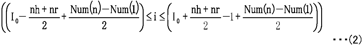
このように取出部4111aで各測定データ集合が取り出されると、検索部4112は、これら取出部4111aで取り出された各測定データ集合において、同じ光路差の測定データを見つけ出す。
Thus, when each extraction data set is extracted by the extraction unit 4111a, the search unit 4112 finds measurement data having the same optical path difference in each measurement data set extracted by the extraction unit 4111a.
本実施形態では、例えば、検索部4112は、1回目の測定で取出部4111aで取り出された測定データ集合とn回目(nは2以上の整数)の測定で取出部4111aで取り出された測定データ集合とにおいて、相互相関の最大値を求めることによって、同じ光路差の測定データを見つけ出している。より具体的には、検索部4112は、まず、サンプリングカウント数(測定点番号)をiとし、1回目の測定で取出部4111aで取り出された測定データ集合をInterferogram1(i)とし、n回目(nは2以上の整数)の測定で取出部4111aで取り出された測定データ集合Interferogramn(i)とする場合に、kの値を0≦k≦(nr-1)の範囲で順次にずらしながら、次式3によってnh点の相互相関関数φ(k)を求める。次に、検索部4112は、相互相関関数φ(k)の最大値max(φ(kmax))を見つける。そして、検索部4112は、この相互相関関数φ(k)の最大値max(φ(kmax))を与える値kmax(シフト量)だけ、n回目(nは2以上の整数)の測定で取出部4111aで取り出された測定データ集合Interferogramn(i)の測定点番号をシフトすることによって、同じ光路差の測定データを見つけ出す。すなわち、1回目の測定で取出部4111aで取り出された測定データ集合Interferogram1(i)における測定点番号j(j∈i)の測定データと、n回目の測定で取出部4111aで取り出された測定データ集合Interferogramn(i)における測定点番号j+kmaxの測定データとが、同じ光路差の測定データである。
In the present embodiment, for example, the search unit 4112 has the measurement data set extracted by the extraction unit 4111a in the first measurement and the measurement data extracted by the extraction unit 4111a in the n-th measurement (n is an integer of 2 or more). The measurement data of the same optical path difference is found by obtaining the maximum value of the cross-correlation in the set. More specifically, the search unit 4112 first sets the sampling count number (measurement point number) to i, sets the measurement data set extracted by the extraction unit 4111a in the first measurement to Interferogram 1 (i), and sets the nth time. When the measurement data set Interferogram n (i) extracted by the extraction unit 4111a in the measurement of (n is an integer of 2 or more), the value of k is sequentially shifted in the range of 0 ≦ k ≦ (nr−1). However, the cross-correlation function φ (k) at the nh point is obtained by the following equation 3. Next, the search unit 4112 finds the maximum value max (φ (k max )) of the cross-correlation function φ (k). Then, the search unit 4112 performs the n-th measurement (n is an integer of 2 or more) for the value k max (shift amount) that gives the maximum value max (φ (k max )) of the cross-correlation function φ (k). The measurement data of the same optical path difference is found by shifting the measurement point number of the measurement data set Interferogram n (i) taken out by the extraction unit 4111a. That is, the measurement data of the measurement point number j (jεi) in the measurement data set Interferogram 1 (i) extracted by the extraction unit 4111a in the first measurement and the measurement extracted by the extraction unit 4111a in the n-th measurement. The measurement data of the measurement point number j + k max in the data set Interferogram n (i) is the measurement data of the same optical path difference.

また例えば、検索部4112は、1回目の測定で取出部4111aで取り出された測定データ集合Interferogram1(i)とn回目(nは2以上の整数)の測定で取出部4111aで取り出された測定データ集合Interferogramn(i)とにおいて、測定点についての差の2乗の和における最小値を求めることによって、同じ光路差の測定データを見つけ出してもよい。より具体的には、検索部4112は、まず、kの値を0≦k≦(nr-1)の範囲で順次にずらしながら、次式4によってnh点の差の2乗和△2(k)を求め、この差の2乗和△2(k)の最小値min(△2(kmin))を見つける。そして、検索部4112は、この差の2乗和△2(k)の最小値min(△2(kmin))を与える値kmin(シフト量)だけ、n回目(nは2以上の整数)の測定で取出部4111aで取り出された測定データ集合Interferogramn(i)の測定点番号をシフトすることによって、同じ光路差の測定データを見つけ出す。すなわち、1回目の測定で取出部4111aで取り出された測定データ集合Interferogram1(i)における測定点番号j(j∈i)の測定データと、n回目の測定で取出部4111aで取り出された測定データ集合Interferogramn(i)における測定点番号j+kminの測定データとが、同じ光路差の測定データである。
In addition, for example, the search unit 4112 uses the measurement data set Interferogram 1 (i) extracted by the extraction unit 4111a in the first measurement and the measurement extracted by the extraction unit 4111a in the n-th measurement (n is an integer of 2 or more). In the data set Interferogram n (i), the measurement data of the same optical path difference may be found by obtaining the minimum value in the sum of the squares of the differences for the measurement points. More specifically, the search unit 4112 first shifts the value of k sequentially within a range of 0 ≦ k ≦ (nr−1), while the square sum of the differences between the nh points Δ 2 (k ) And find the minimum value min (Δ 2 (k min )) of the sum of squares Δ 2 (k) of this difference. Then, the search unit 4112 n times (n is an integer equal to or greater than 2) by a value k min (shift amount) that gives the minimum value min (Δ 2 (k min )) of the square sum Δ 2 (k) of the difference. ), The measurement data of the same optical path difference is found by shifting the measurement point numbers of the measurement data set Interferogram n (i) extracted by the extraction unit 4111a. That is, the measurement data of the measurement point number j (jεi) in the measurement data set Interferogram 1 (i) extracted by the extraction unit 4111a in the first measurement and the measurement extracted by the extraction unit 4111a in the n-th measurement. The measurement data of the measurement point number j + kmin in the data set Interferogram n (i) is the measurement data of the same optical path difference.
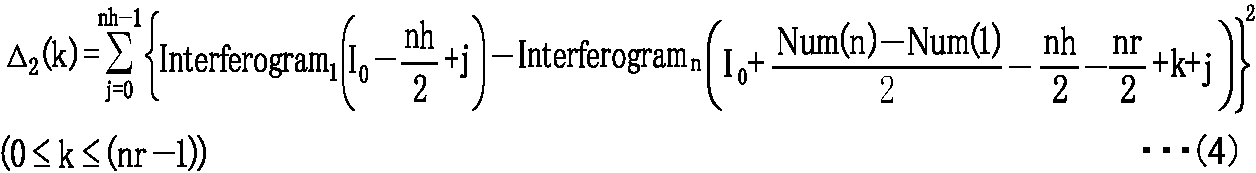
また例えば、検索部4112は、1回目の測定で取出部4111aで取り出された測定データ集合Interferogram1(i)とn回目(nは2以上の整数)の測定で取出部4111aで取り出された測定データ集合Interferogramn(i)とにおいて、測定点についての差の絶対値の和における最小値を求めることによって、同じ光路差の測定データを見つけ出してもよい。より具体的には、検索部4112は、まず、kの値を0≦k≦(nr-1)の範囲で順次にずらしながら、次式5によってnh点の差の絶対値の和△A(k)を求め、この差の絶対値の和△A(k)の最小値min(△A(kmin))を見つける。そして、検索部4112は、この差の絶対値の和△A(k)の最小値min(△A(kmin))を与える値kmin(シフト量)だけ、n回目(nは2以上の整数)の測定で取出部4111aで取り出された測定データ集合Interferogramn(i)の測定点番号をシフトすることによって、同じ光路差の測定データを見つけ出す。すなわち、1回目の測定で取出部4111aで取り出された測定データ集合Interferogram1(i)における測定点番号j(j∈i)の測定データと、n回目の測定で取出部4111aで取り出された測定データ集合Interferogramn(i)における測定点番号j+kminの測定データとが、同じ光路差の測定データである。
In addition, for example, the search unit 4112 uses the measurement data set Interferogram 1 (i) extracted by the extraction unit 4111a in the first measurement and the measurement extracted by the extraction unit 4111a in the n-th measurement (n is an integer of 2 or more). In the data set Interferogram n (i), the measurement data of the same optical path difference may be found by obtaining the minimum value in the sum of the absolute values of the differences for the measurement points. More specifically, the search unit 4112, first, while successively shifting the range of the value of k 0 ≦ k ≦ (nr- 1), the sum of the absolute values of the differences of nh point by the following equation 5 △ A ( k), and find the minimum value min (Δ A (k min )) of the sum Δ A (k) of the absolute values of the differences. Then, the search unit 4112 n times (n is 2 or more) by a value k min (shift amount) that gives the minimum value min (Δ A (k min )) of the sum Δ A (k) of the absolute values of the differences. The measurement data of the same optical path difference is found by shifting the measurement point numbers of the measurement data set Interferogram n (i) extracted by the extraction unit 4111a in the (integer) measurement. That is, the measurement data of the measurement point number j (jεi) in the measurement data set Interferogram 1 (i) extracted by the extraction unit 4111a in the first measurement and the measurement extracted by the extraction unit 4111a in the n-th measurement. The measurement data of the measurement point number j + kmin in the data set Interferogram n (i) is the measurement data of the same optical path difference.

なお、測定点数Num(k)に応じてデータを取り出す範囲の幅(取り出す範囲の開始位置から終了位置までの幅)が、広げられたり狭められたりすることによって、変更されてもよい。例えば、Num(n)≧Num(1)の場合にはn回目の測定データ集合Interferogramn(i)において、次式6-1で表される範囲の次式6-2で表される点数のデータが取り出され、Num(n)<Num(1)の場合にはn回目の測定データ集合Interferogramn(i)において、次式6-3で表される範囲の次式6-4で表される点数のデータが取り出される。
In addition, the width of the range from which data is extracted (the width from the start position to the end position of the extraction range) may be changed according to the number of measurement points Num (k) by being widened or narrowed. For example, in the case of Num (n) ≧ Num (1), in the n-th measurement data set Interferogram n (i), the number of points represented by the following equation 6-2 in the range represented by the following equation 6-1 If Num (n) <Num (1), the data is extracted, and in the nth measurement data set Interferogram n (i), it is expressed by the following expression 6-4 in the range expressed by the following expression 6-3. Data is retrieved.

このように検索部4112で各測定データ集合における同じ光路差のデータが見つけ出されると、積算部4113は、取出部4111aで取り出された各測定データ集合において、検索部4112で見つけ出された同じ光路差の測定データ同士を足し合わせることによって積算インターフェログラムを生成する。
As described above, when the search unit 4112 finds data of the same optical path difference in each measurement data set, the integration unit 4113 uses the same optical path found by the search unit 4112 in each measurement data set extracted by the extraction unit 4111a. An integrated interferogram is generated by adding the difference measurement data together.
より具体的には、まず、m回目の測定でのインターフェログラムFm(xi)は、光路差をxiとし、波数をνjとし、波数νjのスペクトル振幅をB(νj)とし、光路差0の位置をX0とし、波数νjの光路差0の位置における位相をφ(νj)とする場合に、式7で表される。なお、mは、m番目の測定による測定結果であることを表す。
More specifically, first, in the interferogram F m (x i ) in the m-th measurement, the optical path difference is x i , the wave number is ν j, and the spectrum amplitude of the wave number ν j is B (ν j ). And when the optical path difference 0 position is X 0 and the phase of the wave number ν j at the optical path difference 0 position is φ (ν j ), Note that m represents the measurement result of the mth measurement.

したがって、積算インターフェログラムF(xi)は、式8で表される。
Therefore, the integrated interferogram F (x i ) is expressed by Equation 8.

このように積算インターフェログラムが積算部4113で求められると、計算部4114は、積算部4113で生成された積算インターフェログラムを例えば高速フーリエ変換(FFT)することによって被測定光のスペクトルを求める。
When the integrated interferogram is obtained by the integrating unit 4113 in this way, the calculating unit 4114 obtains the spectrum of the light to be measured by performing, for example, fast Fourier transform (FFT) on the integrated interferogram generated by the integrating unit 4113. .
より具体的には、高速フーリエ変換する場合には、サイドローブの発生を低減するために、図6に示すように、光路差0の位置(センターバーストの位置)を中心に左右対称な窓関数Awindow(xi)が掛け合わされてから(式9)、高速フーリエ変換が行われ、被測定光のスペクトルの振幅|Bwindow(νj)|が求められる(式10)。
More specifically, in the case of fast Fourier transform, in order to reduce the occurrence of side lobes, as shown in FIG. 6, a window function that is symmetrical about the position of the optical path difference 0 (center burst position) is used. After A window (x i ) is multiplied (Equation 9), fast Fourier transform is performed to obtain the amplitude | B window (ν j ) | of the spectrum of the measured light (Equation 10).
上記窓関数Awindow(xi)は、適宜な種々の関数を挙げることができるが、例えば、式11-1ないし式11-3で表される関数である。式11-1は、Hanning Window(ハニング窓)関数と呼ばれ、式11-2は、Hamming Window(ハミング窓)関数と呼ばれ、式11-3は、Blackman Window(ブラックマン窓)関数と呼ばれる。
The window function A window (x i ) can include various appropriate functions. For example, the window function A window (x i ) is a function represented by Expression 11-1 to Expression 11-3. Equation 11-1 is called the Hanning Window function, Equation 11-2 is called the Hamming Window function, and Equation 11-3 is called the Blackman Window function. .

このような取り出し範囲の適正化によってスペクトル演算部411は、干渉計11によって得られた被測定光のインターフェログラムを複数積算することによって積算インターフェログラムを生成し、この生成した積算インターフェログラムをフーリエ変換することによって被測定光のスペクトルを求めている。そして、この求めた被測定光のスペクトルは、出力部43に出力される。
By such optimization of the extraction range, the spectrum calculation unit 411 generates an integrated interferogram by integrating a plurality of interferograms of the measured light obtained by the interferometer 11, and the generated integrated interferogram The spectrum of the light to be measured is obtained by Fourier transform. The obtained spectrum of the light to be measured is output to the output unit 43.
以上、説明したように、本実施形態のフーリエ変換型分光計Daおよびこれに実装されたフーリエ変換型分光方法では、インターフェログラムの位置合わせを行うために干渉計11の出力から所定範囲iの出力を取り出す場合に、この取り出す所定範囲iは、光路差形成光学素子における往復の際の振幅情報、本実施形態では移動鏡115における振動の振幅情報に応じて設定される。このため、本実施形態のフーリエ変換型分光計およびフーリエ変換型分光方法は、振幅変動によってセンターバーストの位置が変動するが、振幅情報が参酌されるので、センターバーストを含む範囲をより適切に取り出すことができ、したがって、好適に複数のインターフェログラムを積算することができる。
As described above, in the Fourier transform spectrometer Da according to the present embodiment and the Fourier transform spectrometer implemented in the present embodiment, a predetermined range i is output from the output of the interferometer 11 in order to align the interferogram. When taking out the output, the predetermined range i to be taken out is set according to amplitude information at the time of reciprocation in the optical path difference forming optical element, in this embodiment, according to amplitude information of vibration in the movable mirror 115. For this reason, in the Fourier transform spectrometer and the Fourier transform spectroscopic method of the present embodiment, the position of the center burst varies due to the amplitude variation, but the amplitude information is taken into account, so that a range including the center burst is more appropriately extracted. Therefore, it is possible to preferably integrate a plurality of interferograms.
また、本実施形態のフーリエ変換型分光計Daおよびこれに実装されたフーリエ変換型分光方法では、前記振幅情報として、1回目の測定における振幅中心位置と今回の測定における振幅中心位置とのズレ量が用いられる。このため、このような構成のフーリエ変換型分光計Daは、光路差形成光学素子、本実施形態では移動鏡115が光軸方向に沿って左右対称にずれる場合に好適に対応することができ、インターフェログラムを含む範囲、より好ましくはインターフェログラム全体を完全に含む範囲の測定データをより適切に取り出すことができ、したがって、好適に複数のインターフェログラムを積算することができる。
Further, in the Fourier transform spectrometer Da of this embodiment and the Fourier transform spectroscopic method implemented therein, the amount of deviation between the amplitude center position in the first measurement and the amplitude center position in the current measurement is used as the amplitude information. Is used. For this reason, the Fourier transform type spectrometer Da having such a configuration can suitably cope with a case where the optical path difference forming optical element, in this embodiment, the movable mirror 115 is shifted symmetrically along the optical axis direction, Measurement data in a range including the interferogram, more preferably in a range including the entire interferogram, can be extracted more appropriately. Therefore, a plurality of interferograms can be preferably integrated.
また、本実施形態のフーリエ変換型分光計Daおよびこれに実装されたフーリエ変換型分光方法において、相互相関によって同じ光路差の測定データを見つけ出す場合には、より正確に同じ光路差の測定データを見つけ出すことができる。このため、本実施形態のフーリエ変換型分光計Daおよびこれに実装されたフーリエ変換型分光方法は、好適に複数のインターフェログラムを積算することができる。
In addition, in the Fourier transform spectrometer Da of this embodiment and the Fourier transform spectroscopic method implemented therein, when finding the measurement data of the same optical path difference by cross-correlation, the measurement data of the same optical path difference is more accurately obtained. You can find out. For this reason, the Fourier transform spectrometer Da of the present embodiment and the Fourier transform spectroscopic method mounted thereon can suitably integrate a plurality of interferograms.
また、本実施形態のフーリエ変換型分光計Daおよびこれに実装されたフーリエ変換型分光方法において、差の2乗の和によって同じ光路差の測定データを見つけ出す場合には、より正確に同じ光路差の測定データを見つけ出すことができる。このため、本実施形態のフーリエ変換型分光計Daおよびこれに実装されたフーリエ変換型分光方法は、好適に複数のインターフェログラムを積算することができる。
Further, in the Fourier transform spectrometer Da of the present embodiment and the Fourier transform spectroscopic method mounted thereon, when finding the measurement data of the same optical path difference by the sum of the squares of the differences, the same optical path difference is more accurately detected. The measurement data can be found. For this reason, the Fourier transform spectrometer Da of the present embodiment and the Fourier transform spectroscopic method mounted thereon can suitably integrate a plurality of interferograms.
また、本実施形態のフーリエ変換型分光計Daおよびこれに実装されたフーリエ変換型分光方法において、差の絶対値の和によって同じ光路差の測定データを見つけ出す場合には、より簡易な情報処理で同じ光路差の測定データを見つけ出すことができる。
Further, in the Fourier transform spectrometer Da of this embodiment and the Fourier transform spectroscopic method implemented therein, when finding the measurement data of the same optical path difference by the sum of the absolute values of the differences, simpler information processing is possible. Measurement data with the same optical path difference can be found.
次に、別の実施形態について説明する。
Next, another embodiment will be described.
(第2実施形態)
図7は、第2実施形態におけるフーリエ変換型分光計の構成を示すブロック図である。図8は、第2実施形態のフーリエ変換型分光計における位置測定用光源から放射されるレーザ光のスペクトルを示す図である。図8の横軸は、波数(1/波長)であり、その縦軸は、振幅の大きさである。図9は、フーリエ変換型分光計において、一例として、実測した所定の線幅を持つレーザ光の干渉波形を示す図である。図9(A)は、全体を示し、図9(B)は、端部付近を示し、そして、図9(C)は、極大値付近を示す。図10は、第2実施形態のフーリエ変換型分光計における包絡線検波部の構成を示す回路図である。 (Second Embodiment)
FIG. 7 is a block diagram showing a configuration of a Fourier transform spectrometer in the second embodiment. FIG. 8 is a diagram illustrating a spectrum of laser light emitted from a position measurement light source in the Fourier transform spectrometer according to the second embodiment. The horizontal axis in FIG. 8 is the wave number (1 / wavelength), and the vertical axis is the magnitude of the amplitude. FIG. 9 is a diagram illustrating an interference waveform of laser light having a predetermined line width measured as an example in a Fourier transform spectrometer. 9A shows the whole, FIG. 9B shows the vicinity of the end portion, and FIG. 9C shows the vicinity of the maximum value. FIG. 10 is a circuit diagram showing a configuration of an envelope detector in the Fourier transform spectrometer of the second embodiment.
第2実施形態にかかるフーリエ変換型分光計Dbは、第1実施形態かかるフーリエ変換型分光計Daと同様に、測定対象の被測定光を干渉計で測定し、この測定した被測定光の積算インターフェログラムをフーリエ変換することによって被測定光のスペクトルを求める装置である。ここで、第1実施形態におけるフーリエ変換型分光計Daでは、取出部4111aは、干渉計11の出力から所定範囲iの出力を取り出す場合に、移動鏡115における振動の振幅情報に応じてこの取り出す所定範囲iを設定したが、第2実施形態におけるフーリエ変換型分光計Dbでは、インターフェログラムにおけるセンターバーストの位置を検出するセンターバースト位置検出部がさらに備えられ、取出部4111bは、干渉計11の出力から所定範囲iの出力を取り出す場合に、移動鏡115における振動の振幅情報として前記センターバースト位置検出部によって検出したセンターバーストの位置を用いてこの取り出す所定範囲iを設定し、干渉計11の出力からこの設定した所定範囲iの出力を取り出すものである。
Similar to the Fourier transform spectrometer Da according to the first embodiment, the Fourier transform spectrometer Db according to the second embodiment measures the measured light to be measured with an interferometer, and integrates the measured measured light. This is a device for obtaining a spectrum of measured light by Fourier transforming an interferogram. Here, in the Fourier transform spectrometer Da according to the first embodiment, when the extraction unit 4111a extracts the output of the predetermined range i from the output of the interferometer 11, the extraction unit 4111a extracts this according to the amplitude information of the vibration in the movable mirror 115. Although the predetermined range i is set, the Fourier transform spectrometer Db in the second embodiment further includes a center burst position detection unit that detects the position of the center burst in the interferogram, and the extraction unit 4111b includes the interferometer 11. When the output of the predetermined range i is taken out from the output of, the predetermined range i to be taken out is set using the center burst position detected by the center burst position detection unit as the amplitude information of the vibration in the movable mirror 115, and the interferometer 11. The output of the set predetermined range i is extracted from the output of.
このような第2実施形態におけるフーリエ変換型分光計Dbは、例えば、図7に示すように、干渉計11と、受光処理部20と、位置検出処理部30bと、制御演算部41bと、入力部42と、出力部43とを備えている。第2実施形態のフーリエ変換型分光計Dbにおけるこれら干渉計11、受光処理部20、入力部42および出力部43は、それぞれ、第1実施形態のフーリエ変換型分光計Daにおけるこれら干渉計11、受光処理部20、入力部42および出力部43と同様であるので、その説明を省略する。
For example, as shown in FIG. 7, the Fourier transform spectrometer Db in the second embodiment includes an interferometer 11, a light receiving processing unit 20, a position detection processing unit 30b, a control calculation unit 41b, and an input. A unit 42 and an output unit 43 are provided. The interferometer 11, the light receiving processing unit 20, the input unit 42, and the output unit 43 in the Fourier transform spectrometer Db of the second embodiment are respectively connected to the interferometer 11 in the Fourier transform spectrometer Da of the first embodiment. Since it is the same as that of the light reception processing unit 20, the input unit 42, and the output unit 43, description thereof is omitted.
位置検出処理部30bは、例えば、位置測定用光源31bと、第2受光部36と、ゼロクロス検出部37と、包絡線検波部38とを備えている。そして、位置検出処理部30bは、この位置測定用光源31bから放射されたレーザ光の干渉光を干渉計11で得るために、第1実施形態で図2を用いて説明したように、コリメータレンズ32と、ビームスプリッター33と、ビームスプリッター34と、集光レンズ35とをさらに備えている。すなわち、第2実施形態のフーリエ変換型分光計Dbは、第1実施形態のフーリエ変換型分光計Daに対し、位置測定用光源31aに代え位置測定用光源31bを備え、さらに、包絡線検波部38を備えている。このため、第2実施形態のフーリエ変換型分光計Dbにおける第2受光部36、ゼロクロス検出部37、コリメータレンズ32、ビームスプリッター33、ビームスプリッター34および集光レンズ35は、それぞれ、第1実施形態のフーリエ変換型分光計Daにおける第2受光部36、ゼロクロス検出部37、コリメータレンズ32、ビームスプリッター33、ビームスプリッター34および集光レンズ35と同様であるので、その説明を省略する。
The position detection processing unit 30b includes, for example, a position measurement light source 31b, a second light receiving unit 36, a zero-cross detection unit 37, and an envelope detection unit 38. The position detection processing unit 30b obtains the interference light of the laser light emitted from the position measurement light source 31b with the interferometer 11, as described with reference to FIG. 2 in the first embodiment. 32, a beam splitter 33, a beam splitter 34, and a condenser lens 35 are further provided. That is, the Fourier transform spectrometer Db of the second embodiment is provided with a position measurement light source 31b instead of the position measurement light source 31a with respect to the Fourier transform spectrometer Da of the first embodiment, and further includes an envelope detector. 38. For this reason, the second light receiving unit 36, the zero cross detection unit 37, the collimator lens 32, the beam splitter 33, the beam splitter 34, and the condenser lens 35 in the Fourier transform spectrometer Db of the second embodiment are respectively the first embodiment. Since this is the same as the second light receiving unit 36, the zero cross detection unit 37, the collimator lens 32, the beam splitter 33, the beam splitter 34, and the condensing lens 35 in the Fourier transform spectrometer Da, the description thereof is omitted.
この位置測定用光源31bは、予め設定された所定の線幅を持つレーザ光を放射する光源装置である。位置測定用光源31bは、例えば、所定の線幅を持つレーザ光を放射する半導体レーザを備えて構成される。また例えば、位置測定用光源31bは、単色レーザ光を放射するレーザ装置と、前記レーザ装置から放射された単色レーザ光を高周波重畳する高周波重畳装置とを備え、単色レーザ光を高周波重畳ことによって前記所定の線幅を持つレーザ光を放射するものである。前記所定の線幅は、図9に示すように干渉計11によって得られたレーザ光の干渉光における振幅の大きさが干渉計11の移動鏡115の移動に従って変化する程度の波長幅(周波数幅)である。なお、レーザ光が輝線である場合には、第1実施形態の説明で用いた図4に示すように、このレーザ光の干渉光における振幅の大きさが干渉計11の移動鏡115の移動によって変化しない。このような所定の線幅を持つレーザ光は、一例を挙げると、図8に示すように、中心波数15151.52cm-1に対し半値幅(FWHM)2.3cm-1であるガウス型のプロファイルを持つ。
The position measurement light source 31b is a light source device that emits laser light having a predetermined line width set in advance. The position measuring light source 31b includes, for example, a semiconductor laser that emits laser light having a predetermined line width. Further, for example, the position measuring light source 31b includes a laser device that emits monochromatic laser light, and a high-frequency superimposing device that superimposes the monochromatic laser light emitted from the laser device at a high frequency. A laser beam having a predetermined line width is emitted. As shown in FIG. 9, the predetermined line width is a wavelength width (frequency width) such that the amplitude of the laser light obtained by the interferometer 11 changes in accordance with the movement of the movable mirror 115 of the interferometer 11. ). When the laser beam is a bright line, the magnitude of the amplitude of the laser beam in the interference light depends on the movement of the movable mirror 115 of the interferometer 11 as shown in FIG. 4 used in the description of the first embodiment. It does not change. Laser light having such a predetermined line width, and an example, as shown in FIG. 8, Gaussian profile relative to the central wave number 15151.52Cm -1 is a half-value width (FWHM) 2.3 cm -1 have.
この位置測定用光源31bから射出されたレーザ光は、干渉計11へ入射され、このレーザ光の干渉光は、第2受光部36で受光される。第2受光部36は、レーザ光の干渉光の光強度に応じた電気信号をゼロクロス検出部37および包絡線検波部38のそれぞれへ出力する。
The laser light emitted from the position measuring light source 31 b is incident on the interferometer 11, and the interference light of the laser light is received by the second light receiving unit 36. The second light receiving unit 36 outputs an electrical signal corresponding to the light intensity of the interference light of the laser light to each of the zero cross detection unit 37 and the envelope detection unit 38.
包絡線検波部38は、第2受光部36から入力された、レーザ光の干渉光の光強度に応じた電気信号の包絡線を検出する回路である。包絡線検波部38は、種々の回路構成を採用することができるが、一例を挙げると、図10に示すように、ダイオードDと、ダイオードDのカソード端子と接続されることでダイオードDに直列に接続される抵抗素子Rと、抵抗素子Rに並列に接続されるコンデンサCとを備えて構成され、直列接続のダイオードDおよび抵抗素子Rの両端が入力端とされ、抵抗素子Rの両端が出力端とされる。包絡線検波部38は、このような簡易な回路構成で包絡線を検波することができる。包絡線検波部38は、この検出したレーザ光の干渉光の光強度に応じた電気信号の包絡線を制御演算部41bへ出力する。
The envelope detector 38 is a circuit that detects an envelope of an electric signal input from the second light receiver 36 and corresponding to the light intensity of the interference light of the laser beam. The envelope detector 38 can employ various circuit configurations. For example, as shown in FIG. 10, the envelope detector 38 is connected in series with the diode D by being connected to the diode D and the cathode terminal of the diode D. The resistor element R is connected to the resistor element R, and the capacitor C is connected in parallel to the resistor element R. Both ends of the series-connected diode D and the resistor element R are input ends, and both ends of the resistor element R are The output end. The envelope detector 38 can detect the envelope with such a simple circuit configuration. The envelope detection unit 38 outputs an envelope of an electric signal corresponding to the detected light intensity of the interference light of the laser beam to the control calculation unit 41b.
制御演算部41bは、被測定光のスペクトルを求めるべく、フーリエ変換型分光計Dbの各部を当該各部の機能に応じてそれぞれ制御するものである。そして、制御演算部41bには、プログラムを実行することによって、機能的に、スペクトル演算部411bと、センターバースト位置演算部412とが構成される。
The control calculation unit 41b controls each part of the Fourier transform spectrometer Db according to the function of each part in order to obtain the spectrum of the light to be measured. The control calculation unit 41b functionally includes a spectrum calculation unit 411b and a center burst position calculation unit 412 by executing a program.
センターバースト位置演算部412は、インターフェログラムにおけるセンターバーストの位置を検出するものである。より具体的には、センターバースト位置演算部412は、本実施形態では、包絡線検波部38で検波された包絡線の極大値を与える位置をセンターバーストの位置として検出するものである。このように本実施形態では、センターバーストの位置は、所定の線幅を持つレーザ光を干渉計11に入射させることによって得られた前記レーザ光の干渉光における光強度の包絡線を検波し、この検波された包絡線の極大値を与える位置を検出することによって求められる。
The center burst position calculation unit 412 detects the position of the center burst in the interferogram. More specifically, in this embodiment, the center burst position calculation unit 412 detects a position that gives the maximum value of the envelope detected by the envelope detection unit 38 as the position of the center burst. As described above, in the present embodiment, the position of the center burst detects the envelope of the light intensity in the interference light of the laser light obtained by making the laser light having a predetermined line width enter the interferometer 11, It is obtained by detecting the position giving the maximum value of the detected envelope.
スペクトル演算部411bは、干渉計11で生成された前記被測定光のインターフェログラムを複数積算することによって得られた積算インターフェログラムをフーリエ変換することによって前記被測定光のスペクトルを求めるものである。本実施形態では、例えば、このスペクトル演算部411bには、プログラムを実行することによって、機能的に、取出部4111bと、検索部4112と、積算部4113と、計算部4114が構成される。すなわち、第2実施形態のフーリエ変換型分光計Dbにおけるスペクトル演算部411bは、第1実施形態のフーリエ変換型分光計Daにおけるスペクトル演算部411aに対し、取出部4111aに代え、取出部4111bが機能的に構成される。したがって、第2実施形態のフーリエ変換型分光計Dbにおけるスペクトル演算部411bの検索部4112、積算部4113および計算部4114は、それぞれ、第1実施形態のフーリエ変換型分光計Daにおけるスペクトル演算部411bの検索部4112、積算部4113および計算部4114と同様であるので、その説明を省略する。
The spectrum calculation unit 411b obtains the spectrum of the light to be measured by Fourier-transforming an integrated interferogram obtained by integrating a plurality of interferograms of the light to be measured generated by the interferometer 11. is there. In the present embodiment, for example, the spectrum calculation unit 411b is functionally configured with an extraction unit 4111b, a search unit 4112, an integration unit 4113, and a calculation unit 4114 by executing a program. That is, the spectrum calculation unit 411b in the Fourier transform spectrometer Db of the second embodiment is different from the spectrum calculation unit 411a in the Fourier transform spectrometer Da of the first embodiment in that the extraction unit 4111b functions instead of the extraction unit 4111a. Constructed. Therefore, the search unit 4112, the integration unit 4113, and the calculation unit 4114 of the spectrum calculation unit 411b in the Fourier transform spectrometer Db of the second embodiment are respectively the spectrum calculation unit 411b of the Fourier transform spectrometer Da of the first embodiment. Since the search unit 4112, the integration unit 4113, and the calculation unit 4114 are the same as those of the search unit 4112 of FIG.
取出部4111bは、干渉計11の出力から所定範囲iの出力を取り出す場合に、光路差形成光学素子における前記往復の際の振幅情報、本実施形態では移動鏡115における振動の振幅情報としてセンターバースト位置演算部412によって検出したセンターバーストの位置を用いてこの取り出す所定範囲iを設定し、干渉計11の出力からこの設定した前記所定範囲iの出力を取り出すものである。
When the output of the predetermined range i is extracted from the output of the interferometer 11, the extraction unit 4111 b performs center burst as amplitude information at the time of the reciprocation in the optical path difference forming optical element, in this embodiment, as vibration amplitude information in the movable mirror 115. The predetermined range i to be extracted is set using the position of the center burst detected by the position calculation unit 412, and the output of the set predetermined range i is extracted from the output of the interferometer 11.
本実施形態では、取出部4111bは、より具体的には、例えば、干渉計11の出力から所定範囲iの出力を取り出す場合に、1回目の測定で取り出した所定範囲に対して今回取り出す所定範囲を広げつつ、この所定範囲iの中央位置をセンターバースト位置演算部412で求められたセンターバーストの位置に一致させることによって、この今回取り出す所定範囲iを設定し、干渉計11の出力からこの設定した所定範囲iの出力を取り出すものである。
In the present embodiment, more specifically, for example, when the output of the predetermined range i is extracted from the output of the interferometer 11, the extraction unit 4111 b extracts the predetermined range extracted this time with respect to the predetermined range extracted in the first measurement. The predetermined range i to be extracted this time is set by matching the center position of the predetermined range i with the position of the center burst obtained by the center burst position calculation unit 412, and this setting is made from the output of the interferometer 11. The output of the predetermined range i is taken out.
次に、本実施形態の動作について説明する。図11は、第2実施形態における取出部で取り出す所定範囲を説明するための図(その1)である。図12は、第2実施形態における取出部で取り出す所定範囲を説明するための図(その2)である。図11(A)および図12(A)は、それぞれ、1回目およびn回目(nは2以上の整数)の各測定における各測定結果(AD変換部23の出力)を示し、そして、図11(B)および図12(B)は、それぞれ、1回目およびn回目(nは2以上の整数)の各測定における各包絡線(包絡線検波部38の出力)を示す。
Next, the operation of this embodiment will be described. FIG. 11 is a diagram (No. 1) for describing a predetermined range to be taken out by the takeout unit in the second embodiment. FIG. 12 is a diagram (No. 2) for explaining a predetermined range to be taken out by the take-out unit in the second embodiment. FIGS. 11A and 12A show measurement results (outputs of the AD conversion unit 23) in the first measurement and the n-th measurement (n is an integer of 2 or more), respectively, and FIG. FIG. 12B and FIG. 12B show envelopes (outputs of the envelope detector 38) in the first and n-th measurements (n is an integer of 2 or more), respectively.
測定が開始されると、フーリエ変換型分光計Dbは、測定対象物体SMから放射される被測定光を取り込む。被測定光は、干渉計11bに入射され、第1実施形態のフーリエ変換型分光計Daの干渉計11の場合と同様に、被測定光の干渉光となって第1受光部21で受光され、電気信号となって増幅部22で増幅され、AD変換部23へ出力される。一方、フーリエ変換型分光計Dbは、位置測定用光源31bから放射された所定の半値幅を持つレーザ光も取り込む。このレーザ光は、ビームスプリッター33を介して干渉計11bに入射され、上述と同様に干渉計11bで干渉し、レーザ光の干渉光となってビームスプリッター34を介して第2受光部36で受光される。第2受光部36は、この入射されたレーザ光の干渉光を光電変換してその出力の電気信号をゼロクロス検出部37および包絡線検波部38のそれぞれへ出力する。ゼロクロス検出部37は、前記電気信号のゼロクロスタイミングを検出してAD変換部23へ出力する。このような被測定光およびレーザ光がそれぞれ干渉計11bに取り込まれている間に、干渉計11bの移動鏡115は、制御演算部41bの制御に従って光軸方向に沿って移動される。AD変換部23は、増幅部22からの前記電気信号を、ゼロクロス検出部37からのゼロクロスタイミングでサンプリングしてアナログ信号からディジタル信号へAD変換し、このAD変換したディジタル信号の前記電気信号を制御演算部41bのスペクトル演算部411bへ出力する。このように動作することによって、図11(A)および図12(A)に示すようなインターフェログラムがAD変換部23から制御演算部41bのスペクトル演算部411bに入力される。一方、包絡線検波部38では、前記所定の線幅を持つレーザ光の干渉光に基づく電気信号(第2受光部36の出力)が包絡線検波され、図11(B)および図12(B)に示すような包絡線が包絡線検波部38から制御演算部41bのセンターバースト位置演算部412に入力される。
When the measurement is started, the Fourier transform spectrometer Db takes in the measurement light emitted from the measurement object SM. The measured light is incident on the interferometer 11b and is received by the first light receiving unit 21 as interference light of the measured light, as in the case of the interferometer 11 of the Fourier transform spectrometer Da of the first embodiment. The electric signal is amplified by the amplification unit 22 and output to the AD conversion unit 23. On the other hand, the Fourier transform spectrometer Db also captures laser light having a predetermined half width emitted from the position measuring light source 31b. This laser light is incident on the interferometer 11b through the beam splitter 33, interferes with the interferometer 11b in the same manner as described above, and is received by the second light receiving unit 36 through the beam splitter 34 as interference light of the laser light. Is done. The second light receiving unit 36 photoelectrically converts the incident interference light of the laser beam and outputs the output electric signal to the zero cross detection unit 37 and the envelope detection unit 38, respectively. The zero cross detector 37 detects the zero cross timing of the electrical signal and outputs it to the AD converter 23. While such measured light and laser light are respectively taken into the interferometer 11b, the movable mirror 115 of the interferometer 11b is moved along the optical axis direction under the control of the control calculation unit 41b. The AD conversion unit 23 samples the electric signal from the amplification unit 22 at the zero cross timing from the zero cross detection unit 37 and performs AD conversion from an analog signal to a digital signal. The AD conversion unit 23 controls the electric signal of the AD converted digital signal. It outputs to the spectrum calculating part 411b of the calculating part 41b. By operating in this manner, an interferogram as shown in FIGS. 11A and 12A is input from the AD conversion unit 23 to the spectrum calculation unit 411b of the control calculation unit 41b. On the other hand, in the envelope detection unit 38, an electric signal (output of the second light receiving unit 36) based on the interference light of the laser beam having the predetermined line width is subjected to envelope detection, and FIG. 11 (B) and FIG. ) Is input from the envelope detector 38 to the center burst position calculator 412 of the control calculator 41b.
前記所定の線幅を持つレーザ光の干渉光における光強度の包絡線は、ゼロクロスタイミングは、単色レーザ光の場合と同様であるが、光路差0の位置でその振幅が最も大きく、サイドバンドの位置へ近づくに従ってその振幅が徐々に小さくなるプロファイルを持つ。そして、これら図11(A)と図11(B)との対比および図12(A)と図12(B)との対比から分かるように、前記所定の線幅を持つレーザ光の干渉光における光強度の包絡線は、センターバーストの位置で極大値となる。したがって、所定の線幅を持つレーザ光の干渉光における光強度の包絡線を検波することによってセンターバーストの位置が検出可能である。より具体的には、センターバースト位置演算部412は、包絡線検波部38から入力された包絡線の極大値を検出し、この極大値を与える位置をセンターバーストの位置として求める。そして、センターバースト位置演算部412は、この求めたセンターバーストの位置を取出部4111bへ出力する。
The envelope of the light intensity in the interference light of the laser light having the predetermined line width is the same as in the case of the monochromatic laser light in the zero cross timing, but the amplitude is the largest at the position of the optical path difference 0, and the sideband It has a profile in which the amplitude gradually decreases as it approaches the position. As can be seen from the comparison between FIG. 11A and FIG. 11B and the comparison between FIG. 12A and FIG. 12B, in the interference light of the laser light having the predetermined line width. The envelope of the light intensity reaches a maximum value at the center burst position. Therefore, the position of the center burst can be detected by detecting the envelope of the light intensity in the interference light of the laser light having a predetermined line width. More specifically, the center burst position calculation unit 412 detects the maximum value of the envelope input from the envelope detection unit 38, and obtains the position giving this maximum value as the position of the center burst. Then, the center burst position calculation unit 412 outputs the obtained center burst position to the extraction unit 4111b.
以上の動作によって、取出部4111bには、被測定光のインターフェログラムがAD変換部23から入力され、センターバーストの位置がセンターバースト位置演算部412から入力される。
By the above operation, the interferogram of the light to be measured is input from the AD conversion unit 23 and the position of the center burst is input from the center burst position calculation unit 412 to the extraction unit 4111b.
そして、取出部4111bは、干渉計11の出力から所定範囲iの出力を取り出す場合に、光路差形成光学素子における往復の際の振幅情報、本実施形態では移動鏡115における振動の振幅情報としてセンターバースト位置演算部412によって検出したセンターバーストの位置を用いてこの取り出す所定範囲iを設定し、干渉計11の出力からこの設定した所定範囲iの出力を取り出す。より具体的には、例えば、取出部4111bは、干渉計11の出力から所定範囲iの出力を取り出す場合に、1回目の測定で取り出した所定範囲に対して今回取り出す所定範囲iを広げつつ、センターバーストの位置を中心に所定範囲iを設定し、干渉計11の出力からこの設定した所定範囲iの出力を取り出している。すなわち、1回目の測定における、包絡線の極大値を与える位置および取り出すデータ点数をそれぞれI(1)およびnhとし、n回目の測定における、包絡線の極大値を与える位置および取り出すデータ点数をそれぞれI(n)および(nh+nr)とする場合には、1回目の測定では、前記所定範囲iは、式12で表され(図11(A)および図11(B)参照)、そして、n回目の測定では、前記所定範囲iは、次式の式13で表される(図12(A)および図12(B)参照)。
When the output of the predetermined range i is extracted from the output of the interferometer 11, the extraction unit 4111b is center information as amplitude information when the optical path difference forming optical element is reciprocated, that is, amplitude information of vibration in the movable mirror 115 in this embodiment. The predetermined range i to be extracted is set using the position of the center burst detected by the burst position calculation unit 412, and the output of the set predetermined range i is extracted from the output of the interferometer 11. More specifically, for example, when the extraction unit 4111b extracts the output of the predetermined range i from the output of the interferometer 11, while expanding the predetermined range i extracted this time with respect to the predetermined range extracted in the first measurement, A predetermined range i is set around the center burst position, and the output of the set predetermined range i is extracted from the output of the interferometer 11. That is, the position at which the maximum value of the envelope in the first measurement is given and the number of data points to be taken out are I (1) and nh, respectively, and the position at which the maximum value of the envelope in the nth measurement is given and the number of data points to be taken out are respectively In the case of I (n) and (nh + nr), in the first measurement, the predetermined range i is expressed by Equation 12 (see FIGS. 11A and 11B), and the nth time In the measurement, the predetermined range i is expressed by the following expression 13 (see FIGS. 12A and 12B).


このように取出部4111bで各測定データ集合が取り出されると、検索部4112は、これら取出部4111bで取り出された各測定データ集合において、同じ光路差の測定データを見つけ出す。例えば、検索部4112は、第1実施形態と同様に、相互相関の最大値を求めることによって、または、測定点についての差の2乗の和における最小値を求めることによって、または、測定点についての差の絶対値の和における最小値を求めることによって、同じ光路差の測定データを見つけ出している。
As described above, when each measurement data set is extracted by the extraction unit 4111b, the search unit 4112 finds measurement data having the same optical path difference in each measurement data set extracted by the extraction unit 4111b. For example, as in the first embodiment, the search unit 4112 obtains the maximum value of the cross-correlation, obtains the minimum value in the sum of the squares of the differences about the measurement points, or about the measurement points. The measurement data of the same optical path difference is found by obtaining the minimum value in the sum of the absolute values of the differences.
ここで、第2実施形態では、前記相互相関の最大値を求める場合では、次式14が用いられ、前記測定点についての差の2乗の和における最小値を求める場合では、次式15が用いられ、そして、前記測定点についての差の絶対値の和における最小値を求める場合には、次式16が用いられる。
Here, in the second embodiment, when obtaining the maximum value of the cross-correlation, the following equation 14 is used, and when obtaining the minimum value in the sum of the squares of the differences for the measurement points, the following equation 15 is obtained. When the minimum value in the sum of the absolute values of the differences for the measurement point is used, the following equation 16 is used.
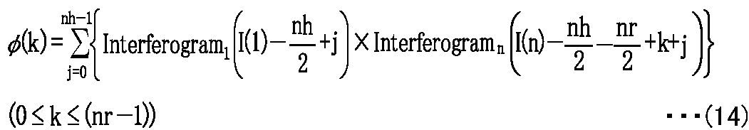


なお、本実施形態においても、包絡線の極大値を与える位置I(n)に応じてデータを取り出す範囲の幅(取り出す範囲の開始位置から終了位置までの幅)が、広げられたり狭められたりすることによって、変更されてもよい。例えば、I(n)≧I(1)の場合にはn回目の測定データ集合Interferogramn(i)において、次式17-1で表される範囲の次式17-2で表される点数のデータが取り出され、I(n)<I(1)の場合にはn回目の測定データ集合Interferogramn(i)において、次式17-3で表される範囲の次式17-4で表される点数のデータが取り出される。
Also in this embodiment, the width of the range from which data is extracted (the width from the start position to the end position of the extraction range) is widened or narrowed according to the position I (n) that gives the maximum value of the envelope. It may be changed by doing. For example, when I (n) ≧ I (1), in the n-th measurement data set Interferogram n (i), the number of points represented by the following expression 17-2 in the range represented by the following expression 17-1 When data is extracted and I (n) <I (1), in the nth measurement data set Interferogram n (i), it is expressed by the following expression 17-4 in the range expressed by the following expression 17-3. Data is retrieved.

このように検索部4112で各測定データ集合における同じ光路差のデータが見つけ出されると、積算部4113は、取出部4111bで取り出された各測定データ集合において、検索部4112で見つけ出された同じ光路差の測定データ同士を足し合わせることによって積算インターフェログラムを生成する。次に、計算部4114は、上記式9および式10によって、この生成した積算インターフェログラムをフーリエ変換することによって被測定光のスペクトルを求める。そして、この求めた被測定光のスペクトルは、出力部43に出力される。
Thus, when the search unit 4112 finds data of the same optical path difference in each measurement data set, the integration unit 4113 uses the same optical path found by the search unit 4112 in each measurement data set extracted by the extraction unit 4111b. An integrated interferogram is generated by adding the difference measurement data together. Next, the calculation unit 4114 obtains the spectrum of the light to be measured by Fourier transforming the generated integrated interferogram according to the above formulas 9 and 10. The obtained spectrum of the light to be measured is output to the output unit 43.
以上、説明したように、本実施形態のフーリエ変換型分光計Dbおよびこれに実装されたフーリエ変換型分光方法では、包絡線検波部38およびセンターバースト位置演算部412によってセンターバーストの位置が検出され、干渉計11の出力から所定範囲iの出力を取り出す場合に、光路差形成光学素子における前記往復の際の振幅情報、本実施形態では移動鏡115における振動の振幅情報として、この検出したセンターバーストの位置が用いられ、この取り出す所定範囲iは、この検出したセンターバーストの位置に応じて設定される。このため、本実施形態のフーリエ変換型分光計Dbおよびフーリエ変換型分光方法は、振幅変動によってセンターバーストの位置が変動するが、センターバーストの位置が実際に検出されて前記所定範囲iが設定されるので、センターバーストを含む範囲の測定データを確実に取り出すことができ、したがって、より好適に複数のインターフェログラムを積算することができる。
As described above, in the Fourier transform spectrometer Db of this embodiment and the Fourier transform spectroscopic method implemented therein, the position of the center burst is detected by the envelope detector 38 and the center burst position calculator 412. When the output of the predetermined range i is taken out from the output of the interferometer 11, this detected center burst is used as amplitude information at the time of the reciprocation in the optical path difference forming optical element, that is, vibration amplitude information in the movable mirror 115 in this embodiment. The predetermined range i to be taken out is set according to the detected center burst position. For this reason, in the Fourier transform spectrometer Db and the Fourier transform spectroscopic method of the present embodiment, the position of the center burst varies due to the amplitude variation, but the position of the center burst is actually detected and the predetermined range i is set. Therefore, measurement data in a range including the center burst can be surely taken out, and accordingly, a plurality of interferograms can be integrated more suitably.
また、第2実施形態のフーリエ変換型分光計Dbは、所定の線幅を持つレーザ光の干渉光における光強度の包絡線を検波することによってセンターバーストの位置を検出するので、例えば、図10に示すような、より簡易な回路構成で検波回路を構成することができる。
Further, since the Fourier transform spectrometer Db of the second embodiment detects the position of the center burst by detecting the envelope of the light intensity in the interference light of the laser light having a predetermined line width, for example, FIG. The detector circuit can be configured with a simpler circuit configuration as shown in FIG.
また、第2実施形態のフーリエ変換型分光計Dbは、レーザ光が所定の線幅を持つレーザ光とされ、センターバーストの位置を検出するための構成として、移動鏡115の位置を検出するための一部の構成が流用されている。より具体的には、位置測定用光源31bから第2受光部36までの構成が共用され、第2受光部36の出力がゼロクロス検出部37および包絡線検波部38のそれぞれに出力される。このため、第2実施形態のフーリエ変換型分光計Dbは、より少ない回路構成でセンターバーストの位置を検出することができる。
Further, the Fourier transform spectrometer Db of the second embodiment is configured such that the laser beam is a laser beam having a predetermined line width, and detects the position of the movable mirror 115 as a configuration for detecting the position of the center burst. A part of the structure is diverted. More specifically, the configuration from the position measurement light source 31 b to the second light receiving unit 36 is shared, and the output of the second light receiving unit 36 is output to each of the zero cross detection unit 37 and the envelope detection unit 38. For this reason, the Fourier transform spectrometer Db of the second embodiment can detect the position of the center burst with a smaller circuit configuration.
また、第2実施形態のフーリエ変換型分光計Dbでは、位置測定用光源31bとして、単色レーザ光を高周波重畳することによって所定の線幅を持つレーザ光を放射するレーザ装置、あるいは、所定の線幅を持つレーザ光を放射する半導体レーザが用いられる。このため、第2実施形態では、より簡易に前記所定の線幅を持つレーザ光を放射する位置測定用光源31bが構成され得る。
In the Fourier transform spectrometer Db of the second embodiment, as the position measurement light source 31b, a laser device that emits laser light having a predetermined line width by superimposing monochromatic laser light at high frequency, or a predetermined line A semiconductor laser that emits laser light having a width is used. For this reason, in the second embodiment, a position measurement light source 31b that emits laser light having the predetermined line width can be configured more simply.
図13は、レーザ光の干渉光における包絡線に基づいてセンターバーストの位置を求める第2態様の方法を説明するための図である。図13(A)は、前記包絡線を示し、図13(B)は、前記包絡線の差分波形を示す。図14は、レーザ光の干渉光における包絡線に基づいてセンターバーストの位置を求める第3態様の方法を説明するための図である。図13および図14の横軸は、光路差(移動鏡115の位置)を示し、これらの縦軸は、レベルを示す。
FIG. 13 is a diagram for explaining a second mode method for obtaining the position of the center burst based on the envelope in the interference light of the laser beam. FIG. 13A shows the envelope, and FIG. 13B shows a differential waveform of the envelope. FIG. 14 is a diagram for explaining the method of the third aspect for obtaining the position of the center burst based on the envelope in the interference light of the laser light. The horizontal axis of FIGS. 13 and 14 indicates the optical path difference (position of the moving mirror 115), and these vertical axes indicate the levels.
また、上述の第2実施形態において、センターバースト位置演算部412は、包絡線検波部38から入力された包絡線の極大値を、移動鏡115の移動(光路差の変化)に従って前記包絡線の振幅値(レベル)が増加から減少に転じた点で検出してもよいが、一例として、図13(A)に示すように前記包絡線が前記極大値付近では移動鏡115の移動(光路差の変化)に従って比較的緩やかに変化する場合には、前記点を精度よく検出することは容易ではない。このため、センターバースト位置演算部412は、包絡線検波部38で検波された包絡線の差分情報に基づいて包絡線検波部38で検波された包絡線の極大値を与える位置をセンターバーストの位置として検出してもよい。
In the second embodiment described above, the center burst position calculation unit 412 calculates the maximum value of the envelope input from the envelope detection unit 38 according to the movement of the movable mirror 115 (change in optical path difference). The detection may be performed at a point where the amplitude value (level) has changed from increase to decrease. As an example, as shown in FIG. 13A, when the envelope is in the vicinity of the maximum value, the movement of the movable mirror 115 (optical path difference). If the point changes relatively slowly according to the change of the above, it is not easy to detect the point with high accuracy. For this reason, the center burst position calculation unit 412 determines the position that gives the maximum value of the envelope detected by the envelope detection unit 38 based on the difference information of the envelope detected by the envelope detection unit 38 as the position of the center burst. You may detect as.
より具体的には、センターバースト位置演算部412は、適宜な間隔で、包絡線上の2点間の差分を求める。例えば、図13(A)に示す包絡線に対し、この包絡線上の2点間の差分を求めて行くと、前記差分情報として、図13(B)に示す差分のグラフが得られる。この差分のグラフにおいて、差分値が正値から負値へ転じるゼロクロス点が前記極大値を与える位置に対応するので、センターバースト位置演算部412は、この差分のグラフにおいて、差分値が正値から負値へ転じるゼロクロス点を求め、ゼロクロス点をセンターバーストの位置とすればよい。
More specifically, the center burst position calculation unit 412 obtains a difference between two points on the envelope at an appropriate interval. For example, when the difference between two points on the envelope is obtained with respect to the envelope shown in FIG. 13A, the difference graph shown in FIG. 13B is obtained as the difference information. In the difference graph, since the zero cross point at which the difference value changes from a positive value to a negative value corresponds to the position where the maximum value is given, the center burst position calculation unit 412 determines that the difference value is from the positive value in the difference graph. A zero cross point that turns to a negative value is obtained, and the zero cross point may be set as the center burst position.
ここで、差分を求める前記間隔が大きいほど、差分値が大きくなり、より精度よくゼロクロス点が検出可能となり、この結果、より精度よくセンターバーストの位置が検出可能となる。
Here, the larger the interval for obtaining the difference, the larger the difference value, and the zero cross point can be detected with higher accuracy. As a result, the position of the center burst can be detected with higher accuracy.
また、このような差分を求める場合において、包絡線の測定結果を格納する記憶素子の記憶容量が制約されて前記間隔があまり大きく取れない場合や、AD変換部23のビット数Zが少なくて分解能があまり大きくない場合では、前記差分は、ゼロクロス点付近では図14に示すように、階段状になってしまう場合がある。このような場合では、ゼロクロス点付近の差分のグラフを最小2乗法によって直線近似し、この近似直線のゼロクロス点を求めることによって、センターバーストの位置が求められてもよい。
Further, when obtaining such a difference, the storage capacity of the storage element that stores the measurement result of the envelope is restricted, and the interval cannot be made too large, or the number of bits Z of the AD conversion unit 23 is small and the resolution is small. When the difference is not so large, the difference may have a stepped shape near the zero cross point as shown in FIG. In such a case, the position of the center burst may be obtained by linearly approximating the difference graph near the zero cross point by the least square method and obtaining the zero cross point of the approximate straight line.
このような包絡線の差分情報を用いることによって、第2実施形態のフーリエ変換型分光計Dbにおけるセンターバースト位置演算部412は、前記包絡線の極大値を与える位置をより精度よく検出することができ、仮に前記包絡線の変化が緩やかであるために前記包絡線の極大値が見分け難い場合であっても、前記包絡線の極大値を与える位置を検出することができる。
By using such difference information of the envelope, the center burst position calculation unit 412 in the Fourier transform spectrometer Db of the second embodiment can more accurately detect the position that gives the maximum value of the envelope. Even if it is difficult to distinguish the maximum value of the envelope because the change of the envelope is gentle, it is possible to detect the position where the maximum value of the envelope is given.
本明細書は、上記のように様々な態様の技術を開示しているが、そのうち主な技術を以下に纏める。
This specification discloses various modes of technology as described above, and the main technologies are summarized below.
一態様にかかるフーリエ変換型分光計は、測定対象の被測定光が入射され、前記被測定光の入射位置から干渉位置までの間に2個の光路を形成する複数の光学素子を備え、前記複数の光学素子には、光軸方向に移動することによって前記2個の光路間に光路差を生じさせる光路差形成光学素子が含まれる干渉計と、前記干渉計で生成された前記被測定光のインターフェログラムを複数積算することによって得られた積算インターフェログラムをフーリエ変換することによって前記被測定光のスペクトルを求めるスペクトル演算部とを備え、前記光路差形成光学素子は、前記被測定光のインターフェログラムを複数生成するために、光軸方向に2回以上往復し、前記スペクトル演算部は、前記干渉計の出力から所定範囲の出力を取り出す場合に、前記光路差形成光学素子における前記往復の際の振幅情報に応じて前記取り出す所定範囲を設定し、前記干渉計の出力からこの設定した前記所定範囲の出力を取り出す取出部と、前記被測定光のインターフェログラムを複数積算するために、前記取出部で取り出された各所定範囲の各出力において、同じ光路差の測定データを見つけ出す検索部と、前記被測定光のインターフェログラムを複数積算するために、前記取出部で取り出された各所定範囲の各出力において、前記検索部で見つけ出された同じ光路差の測定データ同士を足し合わせることによって前記積算インターフェログラムを生成する積算部と、前記積算部で生成された前記積算インターフェログラムをフーリエ変換することによって前記被測定光のスペクトルを求める計算部とを備える。
A Fourier transform spectrometer according to one aspect includes a plurality of optical elements that receive measurement light to be measured and form two optical paths between an incident position of the measurement light and an interference position, The plurality of optical elements include an interferometer including an optical path difference forming optical element that causes an optical path difference between the two optical paths by moving in the optical axis direction, and the light to be measured generated by the interferometer. A spectrum calculation unit that obtains a spectrum of the measured light by performing a Fourier transform on an integrated interferogram obtained by integrating a plurality of interferograms of the optical path difference forming optical element, In order to generate a plurality of interferograms of the interferogram, reciprocates twice or more in the optical axis direction, and the spectrum calculation unit takes out a predetermined range of output from the output of the interferometer A predetermined range to be extracted is set according to amplitude information at the time of the reciprocation in the optical path difference forming optical element, and an extraction unit for extracting the output of the predetermined range from the output of the interferometer; In order to integrate a plurality of interferograms, a search unit for finding measurement data of the same optical path difference at each output in each predetermined range extracted by the extraction unit, and a plurality of interferograms of the measured light Therefore, in each output of each predetermined range extracted by the extraction unit, an integration unit that generates the integrated interferogram by adding together measurement data of the same optical path difference found by the search unit; Calculation for obtaining a spectrum of the light to be measured by Fourier transforming the integrated interferogram generated by the integrating unit Provided with a door.
そして、他の一態様にかかるフーリエ変換型分光方法は、測定対象の被測定光が入射され、前記被測定光の入射位置から干渉位置までの間に2個の光路を形成する複数の光学素子を備え、前記複数の光学素子には、光軸方向に移動することによって前記2個の光路間に光路差を生じさせる光路差形成光学素子が含まれる干渉計と、前記干渉計で生成された前記被測定光のインターフェログラムを複数積算することによって得られた積算インターフェログラムをフーリエ変換することによって前記被測定光のスペクトルを求めるスペクトル演算部とを備え、前記光路差形成光学素子が、前記被測定光のインターフェログラムを複数生成するために、光軸方向に2回以上往復するフーリエ変換型分光計に用いられるフーリエ変換型分光方法において、前記被測定光のスペクトルを求める際に、前記干渉計の出力から所定範囲の出力を取り出す場合に、前記光路差形成光学素子における前記往復の際の振幅情報に応じて前記取り出す所定範囲を設定し、前記干渉計の出力からこの設定した前記所定範囲の出力を取り出す取出工程と、前記被測定光のインターフェログラムを複数積算するために、前記取出工程で取り出された各所定範囲の各出力において、同じ光路差の測定データを見つけ出す検索工程と、前記被測定光のインターフェログラムを複数積算するために、前記取出工程で取り出された各所定範囲の各出力において、前記検索工程で見つけ出された同じ光路差の測定データ同士を足し合わせることによって前記積算インターフェログラムを生成する積算工程と、前記積算工程で生成された前記積算インターフェログラムをフーリエ変換することによって前記被測定光のスペクトルを求める計算工程とを備える。
The Fourier transform spectroscopic method according to another aspect includes a plurality of optical elements that receive light to be measured to be measured and form two optical paths between an incident position of the light to be measured and an interference position. The plurality of optical elements includes an optical path difference forming optical element that generates an optical path difference between the two optical paths by moving in the optical axis direction, and the interferometer generated by the interferometer A spectrum calculation unit that obtains a spectrum of the measured light by Fourier transforming an integrated interferogram obtained by integrating a plurality of interferograms of the measured light, and the optical path difference forming optical element comprises: In order to generate a plurality of interferograms of the light to be measured, a Fourier transform spectroscopic method used in a Fourier transform spectrometer that reciprocates twice or more in the optical axis direction. When obtaining the spectrum of the light to be measured, when extracting a predetermined range of output from the output of the interferometer, the predetermined range to be extracted according to the amplitude information at the time of the reciprocation in the optical path difference forming optical element is An extraction step of setting and extracting the output of the set predetermined range from the output of the interferometer, and each of the predetermined ranges extracted in the extraction step to integrate a plurality of interferograms of the measured light In the output, a search step for finding measurement data of the same optical path difference and a search step in each output of each predetermined range extracted in the extraction step to integrate a plurality of interferograms of the light under measurement An integration step of generating the integrated interferogram by adding together the measurement data of the same optical path difference that has been issued, and the integration step The product is the integrated interferogram was and a calculation step of obtaining a spectrum of the light to be measured by Fourier transform.
このような構成のフーリエ変換型分光計およびフーリエ変換型分光方法では、前記干渉計の出力から所定範囲の出力を取り出す場合に、この取り出す所定範囲は、光路差形成光学素子における往復の際の振幅情報に応じて設定される。このため、このような構成のフーリエ変換型分光計およびフーリエ変換型分光方法は、光路差形成光学素子における往復の際の振幅情報が参酌されるから、インターフェログラムを含む範囲の測定データをより適切に取り出すことができ、したがって、好適に複数のインターフェログラムを積算することができる。
In the Fourier transform spectrometer and the Fourier transform spectroscopic method having such a configuration, when the output of a predetermined range is extracted from the output of the interferometer, the predetermined range to be extracted is the amplitude when the optical path difference forming optical element is reciprocated. Set according to information. For this reason, in the Fourier transform spectrometer and the Fourier transform spectroscopic method having such a configuration, since amplitude information at the time of reciprocation in the optical path difference forming optical element is taken into account, measurement data in a range including an interferogram is more obtained. Therefore, it is possible to appropriately extract a plurality of interferograms.
また、他の一態様では、上述のフーリエ変換型分光計において、前記取出部で用いられる前記振幅情報は、1回目の測定における前記往復の中心位置と今回の測定における前記往復の中心位置とのズレ量である。
Further, in another aspect, in the above-described Fourier transform spectrometer, the amplitude information used in the extraction unit is obtained by calculating the center position of the reciprocation in the first measurement and the center position of the reciprocation in the current measurement. This is the amount of deviation.
このような構成のフーリエ変換型分光計では、前記振幅情報として、1回目の測定における前記往復の中心位置と今回の測定における前記往復の中心位置とのズレ量が用いられる。このため、このような構成のフーリエ変換型分光計は、光路差形成光学素子が左右対称にずれる場合に好適に対応することができ、インターフェログラムを含む範囲の測定データをより適切に取り出すことができ、したがって、好適に複数のインターフェログラムを積算することができる。
In the Fourier transform spectrometer having such a configuration, a deviation amount between the reciprocal center position in the first measurement and the reciprocal center position in the current measurement is used as the amplitude information. For this reason, the Fourier transform spectrometer having such a configuration can suitably cope with a case where the optical path difference forming optical element is shifted left-right symmetrically, and more appropriately extracts measurement data in a range including the interferogram. Therefore, a plurality of interferograms can be preferably integrated.
また、他の一態様では、上述のフーリエ変換型分光計において、インターフェログラムにおけるセンターバーストの位置を検出するセンターバースト位置検出部をさらに備え、前記取出部は、前記干渉計の出力から所定範囲の出力を取り出す場合に、前記光路差形成光学素子における前記往復の際の振幅情報として前記センターバースト位置検出部によって検出したセンターバーストの位置を用いて前記取り出す所定範囲を設定し、前記干渉計の出力からこの設定した前記所定範囲の出力を取り出す。
In another aspect, the Fourier transform spectrometer described above further includes a center burst position detection unit that detects a position of the center burst in the interferogram, and the extraction unit has a predetermined range from the output of the interferometer. When the output of the optical path difference forming optical element is taken out, the predetermined range to be taken out is set using the position of the center burst detected by the center burst position detecting unit as amplitude information at the time of the reciprocation in the optical path difference forming optical element, and the interferometer The output of the set predetermined range is taken out from the output.
このような構成のフーリエ変換型分光計では、センターバースト位置検出部によってセンターバーストの位置が検出される。このため、このような構成のフーリエ変換型分光計は、センターバーストを含む範囲の測定データを確実に取り出すことができ、したがって、より好適に複数のインターフェログラムを積算することができる。
In the Fourier transform spectrometer having such a configuration, the position of the center burst is detected by the center burst position detector. For this reason, the Fourier transform spectrometer having such a configuration can reliably extract measurement data in a range including the center burst, and can more preferably integrate a plurality of interferograms.
また、他の一態様では、上述のフーリエ変換型分光計において、前記センターバースト位置検出部は、所定の線幅を持つレーザ光を前記干渉計に入射させることによって得られた前記レーザ光の干渉光における光強度の包絡線を検波し、前記検波された包絡線の極大値を与える位置を前記センターバーストの位置として検出する。
According to another aspect, in the above-described Fourier transform spectrometer, the center burst position detection unit may interfere with the laser light obtained by causing laser light having a predetermined line width to enter the interferometer. An envelope of light intensity in the light is detected, and a position giving the maximum value of the detected envelope is detected as the position of the center burst.
このような構成のフーリエ変換型分光計は、所定の線幅を持つレーザ光の干渉光における光強度の包絡線を検波することによって前記センターバーストの位置を検出するので、より簡易な回路構成で検波回路を構成することができる。
Since the Fourier transform spectrometer having such a configuration detects the position of the center burst by detecting the envelope of the light intensity in the interference light of the laser beam having a predetermined line width, it has a simpler circuit configuration. A detection circuit can be configured.
また、マイケルソン干渉計では移動鏡の位置を検出するために、例えば、レーザ光の干渉光が利用され、前記レーザ光の干渉光におけるゼロクロスタイミングがサンプリングタイミングとされる。上記構成のフーリエ変換型分光計は、このレーザ光を前記位置測定用光源の前記所定の線幅を持つレーザ光とすることで、移動鏡の位置を検出するための一部の構成を、前記センターバーストの位置を検出するための構成の一部と兼用することができる。このため、上記構成のフーリエ変換型分光計は、より少ない回路構成で前記センターバーストの位置を検出することができる。
In the Michelson interferometer, for example, the interference light of the laser beam is used to detect the position of the movable mirror, and the zero cross timing in the interference light of the laser beam is set as the sampling timing. In the Fourier transform spectrometer having the above configuration, a part of the configuration for detecting the position of the movable mirror is obtained by using the laser beam as the laser beam having the predetermined line width of the position measurement light source. It can also be used as a part of the configuration for detecting the position of the center burst. For this reason, the Fourier transform spectrometer having the above configuration can detect the position of the center burst with a smaller circuit configuration.
また、他の一態様では、これら上述のフーリエ変換型分光計において、前記位置測定用光源は、単色レーザ光を高周波重畳することによって前記所定の線幅を持つレーザ光を放射するレーザ装置である。
According to another aspect, in the above-described Fourier transform spectrometer, the position measurement light source is a laser device that emits laser light having the predetermined line width by superimposing monochromatic laser light at high frequency. .
上記構成によれば、より簡易に前記所定の線幅を持つレーザ光を放射する位置測定用光源が構成される。
According to the above configuration, a position measurement light source that emits laser light having the predetermined line width is configured more simply.
また、他の一態様では、これら上述のフーリエ変換型分光計において、前記位置測定用光源は、前記所定の線幅を持つレーザ光を放射する半導体レーザである。
In another aspect, in the above-described Fourier transform spectrometer, the position measurement light source is a semiconductor laser that emits laser light having the predetermined line width.
上記構成によれば、より簡易に前記所定の線幅を持つレーザ光を放射する位置測定用光源が構成される。
According to the above configuration, a position measurement light source that emits laser light having the predetermined line width is configured more simply.
また、他の一態様では、これら上述のフーリエ変換型分光計において、前記センターバースト位置検出部は、前記包絡線検波部で検波された包絡線の差分情報に基づいて前記包絡線検波部で検波された包絡線の極大値を与える位置を前記センターバーストの位置として検出する。
Further, in another aspect, in the above-described Fourier transform spectrometer, the center burst position detection unit is detected by the envelope detection unit based on difference information of the envelope detected by the envelope detection unit. A position that gives the maximum value of the envelope is detected as the position of the center burst.
このような構成のフーリエ変換型分光計は、前記包絡線の極大値を与える位置をより精度よく検出することができ、仮に前記包絡線の変化が緩やかであるために前記包絡線の極大値が見分け難い場合であっても、前記包絡線の極大値を与える位置を検出することができる。
The Fourier transform spectrometer having such a configuration can detect the position where the maximum value of the envelope is given more accurately, and since the change of the envelope is gentle, the maximum value of the envelope is Even if it is difficult to distinguish, it is possible to detect the position that gives the maximum value of the envelope.
また、他の一態様では、これら上述のフーリエ変換型分光計において、前記検索部は、1回目の測定で前記取出部で取り出された所定範囲の出力とn回目(nは2以上の整数)の測定で前記取出部で取り出された所定範囲の出力とにおいて、相互相関の最大値を求めることによって、同じ光路差の測定データを見つけ出す。
In another aspect, in the above-described Fourier transform spectrometer, the search unit outputs a predetermined range of outputs extracted by the extraction unit in the first measurement and the nth (n is an integer of 2 or more). In this measurement, the maximum value of the cross-correlation is obtained with respect to the output within the predetermined range extracted by the extraction unit, and measurement data having the same optical path difference is found.
このような構成のフーリエ変換型分光計では、相互相関によって同じ光路差の測定データが見つけ出されるので、より正確に同じ光路差の測定データを見つけ出すことができる。このため、このような構成のフーリエ変換型分光計は、好適に複数のインターフェログラムを積算することができる。
In the Fourier transform spectrometer having such a configuration, measurement data with the same optical path difference is found by cross-correlation, so that measurement data with the same optical path difference can be found more accurately. Therefore, the Fourier transform spectrometer having such a configuration can preferably integrate a plurality of interferograms.
また、他の一態様では、これら上述のフーリエ変換型分光計において、前記検索部は、1回目の測定で前記取出部で取り出された所定範囲の出力とn回目(nは2以上の整数)の測定で前記取出部で取り出された所定範囲の出力とにおいて、測定点についての差の2乗の和における最小値を求めることによって、同じ光路差の測定データを見つけ出す。
In another aspect, in the above-described Fourier transform spectrometer, the search unit outputs a predetermined range of outputs extracted by the extraction unit in the first measurement and the nth (n is an integer of 2 or more). The measurement data of the same optical path difference is found by obtaining the minimum value in the sum of the squares of the differences at the measurement points with respect to the output in the predetermined range taken out by the take-out unit in the above measurement.
このような構成のフーリエ変換型分光計では、差の2乗の和によって同じ光路差の測定データが見つけ出されるので、より正確に同じ光路差の測定データを見つけ出すことができる。このため、このような構成のフーリエ変換型分光計は、好適に複数のインターフェログラムを積算することができる。
In the Fourier transform spectrometer having such a configuration, the measurement data with the same optical path difference is found by the sum of the squares of the differences, so that the measurement data with the same optical path difference can be found more accurately. Therefore, the Fourier transform spectrometer having such a configuration can preferably integrate a plurality of interferograms.
また、他の一態様では、これら上述のフーリエ変換型分光計において、前記検索部は、1回目の測定で前記取出部で取り出された所定範囲の出力とn回目(nは2以上の整数)の測定で前記取出部で取り出された所定範囲の出力とにおいて、測定点についての差の絶対値の和における最小値を求めることによって、同じ光路差の測定データを見つけ出す。
In another aspect, in the above-described Fourier transform spectrometer, the search unit outputs a predetermined range of outputs extracted by the extraction unit in the first measurement and the nth (n is an integer of 2 or more). The measurement data of the same optical path difference is found by obtaining the minimum value in the sum of the absolute values of the differences at the measurement points with respect to the output in the predetermined range extracted by the extraction unit in the measurement.
このような構成のフーリエ変換型分光計では、差の絶対値の和によって同じ光路差の測定データが見つけ出されるので、より簡易な情報処理で同じ光路差の測定データを見つけ出すことができる。
In the Fourier transform spectrometer having such a configuration, the measurement data of the same optical path difference is found by the sum of the absolute values of the differences. Therefore, the measurement data of the same optical path difference can be found by simpler information processing.
この出願は、2011年5月31日に出願された日本国特許出願特願2011-122352を基礎とするものであり、その内容は、本願に含まれるものである。
This application is based on Japanese Patent Application No. 2011-122352 filed on May 31, 2011, the contents of which are included in this application.
本発明を表現するために、上述において図面を参照しながら実施形態を通して本発明を適切且つ十分に説明したが、当業者であれば上述の実施形態を変更および/または改良することは容易に為し得ることであると認識すべきである。したがって、当業者が実施する変更形態または改良形態が、請求の範囲に記載された請求項の権利範囲を離脱するレベルのものでない限り、当該変更形態または当該改良形態は、当該請求項の権利範囲に包括されると解釈される。
In order to express the present invention, the present invention has been properly and fully described through the embodiments with reference to the drawings. However, those skilled in the art can easily change and / or improve the above-described embodiments. It should be recognized that this is possible. Therefore, unless the modifications or improvements implemented by those skilled in the art are at a level that departs from the scope of the claims recited in the claims, the modifications or improvements are not covered by the claims. It is interpreted that it is included in
本発明によれば、フーリエ変換型分光計およびフーリエ変換型分光方法を提供することができる。
According to the present invention, a Fourier transform spectrometer and a Fourier transform spectrometer can be provided.
Claims (11)
- 測定対象の被測定光が入射され、前記被測定光の入射位置から干渉位置までの間に2個の光路を形成する複数の光学素子を備え、前記複数の光学素子には、光軸方向に移動することによって前記2個の光路間に光路差を生じさせる光路差形成光学素子が含まれる干渉計と、
前記干渉計で生成された前記被測定光のインターフェログラムを複数積算することによって得られた積算インターフェログラムをフーリエ変換することによって前記被測定光のスペクトルを求めるスペクトル演算部とを備え、
前記光路差形成光学素子は、前記被測定光のインターフェログラムを複数生成するために、光軸方向に2回以上往復し、
前記スペクトル演算部は、
前記干渉計の出力から所定範囲の出力を取り出す場合に、前記光路差形成光学素子における前記往復の際の振幅情報に応じて前記取り出す所定範囲を設定し、前記干渉計の出力からこの設定した前記所定範囲の出力を取り出す取出部と、
前記被測定光のインターフェログラムを複数積算するために、前記取出部で取り出された各所定範囲の各出力において、同じ光路差の測定データを見つけ出す検索部と、
前記被測定光のインターフェログラムを複数積算するために、前記取出部で取り出された各所定範囲の各出力において、前記検索部で見つけ出された同じ光路差の測定データ同士を足し合わせることによって前記積算インターフェログラムを生成する積算部と、
前記積算部で生成された前記積算インターフェログラムをフーリエ変換することによって前記被測定光のスペクトルを求める計算部とを備えること
を特徴とするフーリエ変換型分光計。 A plurality of optical elements that form two optical paths between an incident position of the light to be measured and an interference position, and the plurality of optical elements have an optical axis direction; An interferometer including an optical path difference forming optical element that causes an optical path difference between the two optical paths by moving; and
A spectrum calculation unit that obtains a spectrum of the measured light by Fourier transforming an integrated interferogram obtained by integrating a plurality of interferograms of the measured light generated by the interferometer,
The optical path difference forming optical element reciprocates twice or more in the optical axis direction in order to generate a plurality of interferograms of the measured light,
The spectrum calculation unit is
When the output of a predetermined range is taken out from the output of the interferometer, the predetermined range to be taken out is set according to the amplitude information at the time of the reciprocation in the optical path difference forming optical element, and the set the output from the interferometer A take-out section for taking out a predetermined range of output;
In order to integrate a plurality of interferograms of the light to be measured, a search unit for finding measurement data of the same optical path difference at each output of each predetermined range extracted by the extraction unit;
In order to integrate a plurality of interferograms of the light to be measured, by adding together the measurement data of the same optical path difference found by the search unit at each output of each predetermined range extracted by the extraction unit An integrating unit for generating the integrated interferogram;
A Fourier transform spectrometer, comprising: a calculation unit that obtains a spectrum of the light to be measured by subjecting the integration interferogram generated by the integration unit to Fourier transform. - 前記取出部で用いられる前記振幅情報は、1回目の測定における前記往復の中心位置と今回の測定における前記往復の中心位置とのズレ量であること
を特徴とする請求項1に記載のフーリエ変換型分光計。 2. The Fourier transform according to claim 1, wherein the amplitude information used in the extraction unit is a shift amount between the center position of the round trip in the first measurement and the center position of the round trip in the current measurement. Type spectrometer. - インターフェログラムにおけるセンターバーストの位置を検出するセンターバースト位置検出部をさらに備え、
前記取出部は、前記干渉計の出力から所定範囲の出力を取り出す場合に、前記光路差形成光学素子における前記往復の際の振幅情報として前記センターバースト位置検出部によって検出したセンターバーストの位置を用いて前記取り出す所定範囲を設定し、前記干渉計の出力からこの設定した前記所定範囲の出力を取り出すこと
を特徴とする請求項1に記載のフーリエ変換型分光計。 A center burst position detector for detecting the position of the center burst in the interferogram,
The extraction unit uses the position of the center burst detected by the center burst position detection unit as amplitude information at the time of the reciprocation in the optical path difference forming optical element when the output of a predetermined range is extracted from the output of the interferometer. The Fourier transform spectrometer according to claim 1, wherein the predetermined range to be extracted is set, and the output of the predetermined range set is extracted from the output of the interferometer. - 前記センターバースト位置検出部は、所定の線幅を持つレーザ光を前記干渉計に入射させることによって得られた前記レーザ光の干渉光における光強度の包絡線を検波し、前記検波された包絡線の極大値を与える位置を前記センターバーストの位置として検出すること
を特徴とする請求項3に記載のフーリエ変換型分光計。 The center burst position detection unit detects an envelope of light intensity in the interference light of the laser light obtained by making laser light having a predetermined line width incident on the interferometer, and detects the detected envelope The Fourier transform spectrometer according to claim 3, wherein a position that gives a local maximum value of is detected as the position of the center burst. - 前記位置測定用光源は、単色レーザ光を高周波重畳することによって前記所定の線幅を持つレーザ光を放射するレーザ装置であること
を特徴とする請求項3または請求項4に記載のフーリエ変換型分光計。 5. The Fourier transform type according to claim 3, wherein the position measurement light source is a laser device that emits laser light having the predetermined line width by superimposing monochromatic laser light at high frequency. Spectrometer. - 前記位置測定用光源は、前記所定の線幅を持つレーザ光を放射する半導体レーザであること
を特徴とする請求項3または請求項4に記載のフーリエ変換型分光計。 The Fourier transform spectrometer according to claim 3 or 4, wherein the position measuring light source is a semiconductor laser that emits laser light having the predetermined line width. - 前記センターバースト位置検出部は、前記包絡線検波部で検波された包絡線の差分情報に基づいて前記包絡線検波部で検波された包絡線の極大値を与える位置を前記センターバーストの位置として検出すること
を特徴とする請求項4ないし請求項6のいずれか1項に記載のフーリエ変換型分光計。 The center burst position detection unit detects a position that gives a maximum value of the envelope detected by the envelope detection unit as a position of the center burst based on difference information of the envelope detected by the envelope detection unit The Fourier transform spectrometer according to any one of claims 4 to 6, wherein: - 前記検索部は、1回目の測定で前記取出部で取り出された所定範囲の出力とn回目(nは2以上の整数)の測定で前記取出部で取り出された所定範囲の出力とにおいて、相互相関の最大値を求めることによって、同じ光路差の測定データを見つけ出すこと
を特徴とする請求項1ないし請求項7のいずれか1項に記載のフーリエ変換型分光計。 The search unit includes a predetermined range of output extracted by the extraction unit in the first measurement and an output of the predetermined range extracted by the extraction unit in the n-th measurement (n is an integer of 2 or more). The Fourier transform spectrometer according to any one of claims 1 to 7, wherein measurement data having the same optical path difference is found by obtaining a maximum value of correlation. - 前記検索部は、1回目の測定で前記取出部で取り出された所定範囲の出力とn回目(nは2以上の整数)の測定で前記取出部で取り出された所定範囲の出力とにおいて、測定点についての差の2乗の和における最小値を求めることによって、同じ光路差の測定データを見つけ出すこと
を特徴とする請求項1ないし請求項7のいずれか1項に記載のフーリエ変換型分光計。 The search unit measures a predetermined range of output taken out by the take-out unit in the first measurement and a predetermined range of output taken out by the take-out unit in the n-th measurement (n is an integer of 2 or more). The Fourier transform spectrometer according to any one of claims 1 to 7, wherein measurement data of the same optical path difference is found by obtaining a minimum value in a sum of squares of differences of points. . - 前記検索部は、1回目の測定で前記取出部で取り出された所定範囲の出力とn回目(nは2以上の整数)の測定で前記取出部で取り出された所定範囲の出力とにおいて、測定点についての差の絶対値の和における最小値を求めることによって、同じ光路差の測定データを見つけ出すこと
を特徴とする請求項1ないし請求項7のいずれか1項に記載のフーリエ変換型分光計。 The search unit measures a predetermined range of output taken out by the take-out unit in the first measurement and a predetermined range of output taken out by the take-out unit in the n-th measurement (n is an integer of 2 or more). The Fourier transform spectrometer according to any one of claims 1 to 7, wherein measurement data of the same optical path difference is found by obtaining a minimum value in a sum of absolute values of differences of points. . - 測定対象の被測定光が入射され、前記被測定光の入射位置から干渉位置までの間に2個の光路を形成する複数の光学素子を備え、前記複数の光学素子には、光軸方向に移動することによって前記2個の光路間に光路差を生じさせる光路差形成光学素子が含まれる干渉計と、前記干渉計で生成された前記被測定光のインターフェログラムを複数積算することによって得られた積算インターフェログラムをフーリエ変換することによって前記被測定光のスペクトルを求めるスペクトル演算部とを備え、前記光路差形成光学素子が、前記被測定光のインターフェログラムを複数生成するために、光軸方向に2回以上往復するフーリエ変換型分光計に用いられるフーリエ変換型分光方法において、
前記被測定光のスペクトルを求める際に、
前記干渉計の出力から所定範囲の出力を取り出す場合に、前記光路差形成光学素子における前記往復の際の振幅情報に応じて前記取り出す所定範囲を設定し、前記干渉計の出力からこの設定した前記所定範囲の出力を取り出す取出工程と、
前記被測定光のインターフェログラムを複数積算するために、前記取出工程で取り出された各所定範囲の各出力において、同じ光路差の測定データを見つけ出す検索工程と、
前記被測定光のインターフェログラムを複数積算するために、前記取出工程で取り出された各所定範囲の各出力において、前記検索工程で見つけ出された同じ光路差の測定データ同士を足し合わせることによって前記積算インターフェログラムを生成する積算工程と、
前記積算工程で生成された前記積算インターフェログラムをフーリエ変換することによって前記被測定光のスペクトルを求める計算工程とを備えること
を特徴とするフーリエ変換型分光方法。 A plurality of optical elements that form two optical paths between an incident position of the light to be measured and an interference position, and the plurality of optical elements have an optical axis direction; It is obtained by accumulating a plurality of interferograms of the measured light generated by the interferometer including an optical path difference forming optical element that causes an optical path difference between the two optical paths by moving and the interferometer. A spectrum calculation unit that obtains a spectrum of the light to be measured by performing a Fourier transform on the obtained integrated interferogram, and the optical path difference forming optical element generates a plurality of interferograms of the light to be measured. In a Fourier transform spectroscopic method used in a Fourier transform spectrometer that reciprocates twice or more in the optical axis direction,
When obtaining the spectrum of the light to be measured,
When the output of a predetermined range is taken out from the output of the interferometer, the predetermined range to be taken out is set according to the amplitude information at the time of the reciprocation in the optical path difference forming optical element, and the set the output from the interferometer An extraction process for extracting a predetermined range of output;
In order to integrate a plurality of interferograms of the light to be measured, a search step of finding measurement data of the same optical path difference in each output of each predetermined range extracted in the extraction step;
In order to integrate a plurality of interferograms of the light to be measured, by adding together the measurement data of the same optical path difference found in the search step at each output of each predetermined range taken out in the extraction step An integration step for generating the integrated interferogram;
And a calculation step of obtaining a spectrum of the measured light by subjecting the integration interferogram generated in the integration step to Fourier transform.
Priority Applications (1)
| Application Number | Priority Date | Filing Date | Title |
|---|---|---|---|
| JP2013517823A JP5846202B2 (en) | 2011-05-31 | 2012-04-13 | Fourier transform spectrometer and Fourier transform spectroscopic method |
Applications Claiming Priority (2)
| Application Number | Priority Date | Filing Date | Title |
|---|---|---|---|
| JP2011-122352 | 2011-05-31 | ||
| JP2011122352 | 2011-05-31 |
Publications (1)
| Publication Number | Publication Date |
|---|---|
| WO2012164810A1 true WO2012164810A1 (en) | 2012-12-06 |
Family
ID=47258688
Family Applications (1)
| Application Number | Title | Priority Date | Filing Date |
|---|---|---|---|
| PCT/JP2012/002577 WO2012164810A1 (en) | 2011-05-31 | 2012-04-13 | Fourier transform spectrometer and fourier transform spectroscopy method |
Country Status (2)
| Country | Link |
|---|---|
| JP (1) | JP5846202B2 (en) |
| WO (1) | WO2012164810A1 (en) |
Cited By (2)
| Publication number | Priority date | Publication date | Assignee | Title |
|---|---|---|---|---|
| WO2013179572A1 (en) * | 2012-05-29 | 2013-12-05 | コニカミノルタ株式会社 | Fourier transform spectrometer and fourier transform spectroscopic method |
| WO2019009401A1 (en) * | 2017-07-06 | 2019-01-10 | 浜松ホトニクス株式会社 | Optical module |
Citations (4)
| Publication number | Priority date | Publication date | Assignee | Title |
|---|---|---|---|---|
| JPS6238324A (en) * | 1985-08-12 | 1987-02-19 | Shimadzu Corp | Fourier transform type spectrophotometer |
| JPH1090065A (en) * | 1996-09-11 | 1998-04-10 | Kurabo Ind Ltd | Data processor and data processing method for fourier transform spectrometer |
| JP2008134133A (en) * | 2006-11-28 | 2008-06-12 | Shimadzu Corp | Fourier transform infrared spectrophotometer |
| JP2011080854A (en) * | 2009-10-07 | 2011-04-21 | Konica Minolta Holdings Inc | Fourier transform spectroscope |
Family Cites Families (2)
| Publication number | Priority date | Publication date | Assignee | Title |
|---|---|---|---|---|
| JP3497927B2 (en) * | 1995-07-13 | 2004-02-16 | 日本分光株式会社 | Interferogram integrator |
| AT413765B (en) * | 2004-06-24 | 2006-05-15 | Ctr Carinthian Tech Res Ag | ARRANGEMENT FOR CONSTRUCTION OF A MINIATURIZED FOURIER TRANSFORM INTERFEROMETER FOR OPTICAL RADIATION ACCORDING TO THE MICHELSON- BZW. A PRINCIPLE DERIVED FROM IT |
-
2012
- 2012-04-13 JP JP2013517823A patent/JP5846202B2/en not_active Expired - Fee Related
- 2012-04-13 WO PCT/JP2012/002577 patent/WO2012164810A1/en active Application Filing
Patent Citations (4)
| Publication number | Priority date | Publication date | Assignee | Title |
|---|---|---|---|---|
| JPS6238324A (en) * | 1985-08-12 | 1987-02-19 | Shimadzu Corp | Fourier transform type spectrophotometer |
| JPH1090065A (en) * | 1996-09-11 | 1998-04-10 | Kurabo Ind Ltd | Data processor and data processing method for fourier transform spectrometer |
| JP2008134133A (en) * | 2006-11-28 | 2008-06-12 | Shimadzu Corp | Fourier transform infrared spectrophotometer |
| JP2011080854A (en) * | 2009-10-07 | 2011-04-21 | Konica Minolta Holdings Inc | Fourier transform spectroscope |
Cited By (18)
| Publication number | Priority date | Publication date | Assignee | Title |
|---|---|---|---|---|
| WO2013179572A1 (en) * | 2012-05-29 | 2013-12-05 | コニカミノルタ株式会社 | Fourier transform spectrometer and fourier transform spectroscopic method |
| JPWO2013179572A1 (en) * | 2012-05-29 | 2016-01-18 | コニカミノルタ株式会社 | Fourier transform spectrometer and Fourier transform spectroscopic method |
| WO2019009401A1 (en) * | 2017-07-06 | 2019-01-10 | 浜松ホトニクス株式会社 | Optical module |
| WO2019009404A1 (en) * | 2017-07-06 | 2019-01-10 | 浜松ホトニクス株式会社 | Optical module |
| JP6496463B1 (en) * | 2017-07-06 | 2019-04-03 | 浜松ホトニクス株式会社 | Optical module |
| CN110799817A (en) * | 2017-07-06 | 2020-02-14 | 浜松光子学株式会社 | Optical assembly |
| JPWO2019009401A1 (en) * | 2017-07-06 | 2020-04-30 | 浜松ホトニクス株式会社 | Optical module |
| EP3650820A4 (en) * | 2017-07-06 | 2021-04-21 | Hamamatsu Photonics K.K. | Optical module |
| US11054309B2 (en) | 2017-07-06 | 2021-07-06 | Hamamatsu Photonics K.K. | Optical module |
| US11067380B2 (en) | 2017-07-06 | 2021-07-20 | Hamamatsu Photonics K.K. | Optical module |
| US11187579B2 (en) | 2017-07-06 | 2021-11-30 | Hamamatsu Photonics K.K. | Optical device |
| US11209260B2 (en) | 2017-07-06 | 2021-12-28 | Hamamatsu Photonics K.K. | Optical module having high-accuracy spectral analysis |
| JP7233365B2 (en) | 2017-07-06 | 2023-03-06 | 浜松ホトニクス株式会社 | optical module |
| US11624605B2 (en) | 2017-07-06 | 2023-04-11 | Hamamatsu Photonics K.K. | Mirror unit and optical module |
| US11629947B2 (en) | 2017-07-06 | 2023-04-18 | Hamamatsu Photonics K.K. | Optical device |
| US11629946B2 (en) | 2017-07-06 | 2023-04-18 | Hamamatsu Photonics K.K. | Mirror unit and optical module |
| US11635290B2 (en) | 2017-07-06 | 2023-04-25 | Hamamatsu Photonics K.K. | Optical module |
| US11879731B2 (en) | 2017-07-06 | 2024-01-23 | Hamamatsu Photonics K.K. | Mirror unit and optical module |
Also Published As
| Publication number | Publication date |
|---|---|
| JP5846202B2 (en) | 2016-01-20 |
| JPWO2012164810A1 (en) | 2014-07-31 |
Similar Documents
| Publication | Publication Date | Title |
|---|---|---|
| JP5725165B2 (en) | Fourier transform spectrometer and Fourier transform spectroscopic method | |
| CN109791896B (en) | Speeding up spectral measurements in semiconductor device fabrication | |
| US8203715B2 (en) | Knowledge based spectrometer | |
| RU2569052C1 (en) | Method to compensate frequency drift in interferometer | |
| JP5846202B2 (en) | Fourier transform spectrometer and Fourier transform spectroscopic method | |
| CN113074665B (en) | Line profile measuring method based on spectral resolution interference | |
| JP5891955B2 (en) | Timing generation apparatus for Fourier transform spectrometer and method, Fourier transform spectrometer and method | |
| JP5915737B2 (en) | Fourier transform spectrometer and Fourier transform spectroscopic method | |
| EP3370047A1 (en) | Spectrum measuring device, spectroscopic device, and spectroscopic system | |
| WO2014199888A1 (en) | Fourier transform spectrometer and spectroscopy and fourier transform spectrometer timing generation device | |
| CN107407601B (en) | Spectrometer system and method for compensating for time-periodic perturbations of an interferogram produced by the spectrometer system | |
| KR20210049679A (en) | Optical measurement apparatus, wavelength calibration method and standard sample | |
| CN113677951B (en) | Optical distance measuring device | |
| JP5737386B2 (en) | Fourier transform spectrometer and Fourier transform spectroscopic method | |
| JP5974929B2 (en) | Stray light correction method and Fourier transform type spectroscopic device using the same | |
| Kenda et al. | A compact and portable IR analyzer: progress of a MOEMS FT-IR system for mid-IR sensing | |
| JP2014137328A (en) | Fourier transform type spectrometer and wavelength calibration method of fourier transform type spectrometer | |
| JP2014013185A (en) | Spectral imaging device adjustment method and spectral imaging system | |
| JP5835101B2 (en) | Fourier transform spectrometer, Fourier transform spectroscopic method, and attachment for Fourier transform spectrometer | |
| JP2006300661A (en) | Interferometer and fourier spectral device | |
| JP2014228281A (en) | Fourier transform type spectrometer and method for calibrating fourier transform type spectrometer | |
| US11561080B2 (en) | Optical sensor for surface inspection and metrology | |
| US11703461B2 (en) | Optical sensor for surface inspection and metrology | |
| JP2006300664A (en) | Fourier spectral device and measuring timing detection method | |
| EP1321738A2 (en) | Interferometric system and method for measuring length |
Legal Events
| Date | Code | Title | Description |
|---|---|---|---|
| 121 | Ep: the epo has been informed by wipo that ep was designated in this application |
Ref document number: 12792262 Country of ref document: EP Kind code of ref document: A1 |
|
| ENP | Entry into the national phase |
Ref document number: 2013517823 Country of ref document: JP Kind code of ref document: A |
|
| NENP | Non-entry into the national phase |
Ref country code: DE |
|
| 122 | Ep: pct application non-entry in european phase |
Ref document number: 12792262 Country of ref document: EP Kind code of ref document: A1 |