WO2012161021A1 - Endoscope - Google Patents
Endoscope Download PDFInfo
- Publication number
- WO2012161021A1 WO2012161021A1 PCT/JP2012/062322 JP2012062322W WO2012161021A1 WO 2012161021 A1 WO2012161021 A1 WO 2012161021A1 JP 2012062322 W JP2012062322 W JP 2012062322W WO 2012161021 A1 WO2012161021 A1 WO 2012161021A1
- Authority
- WO
- WIPO (PCT)
- Prior art keywords
- bending
- shape switching
- guide pipe
- built
- curved shape
- Prior art date
Links
Images


Classifications
-
- A—HUMAN NECESSITIES
- A61—MEDICAL OR VETERINARY SCIENCE; HYGIENE
- A61B—DIAGNOSIS; SURGERY; IDENTIFICATION
- A61B1/00—Instruments for performing medical examinations of the interior of cavities or tubes of the body by visual or photographical inspection, e.g. endoscopes; Illuminating arrangements therefor
- A61B1/005—Flexible endoscopes
- A61B1/008—Articulations
-
- A—HUMAN NECESSITIES
- A61—MEDICAL OR VETERINARY SCIENCE; HYGIENE
- A61B—DIAGNOSIS; SURGERY; IDENTIFICATION
- A61B1/00—Instruments for performing medical examinations of the interior of cavities or tubes of the body by visual or photographical inspection, e.g. endoscopes; Illuminating arrangements therefor
- A61B1/00064—Constructional details of the endoscope body
- A61B1/00071—Insertion part of the endoscope body
- A61B1/0008—Insertion part of the endoscope body characterised by distal tip features
- A61B1/00096—Optical elements
-
- A—HUMAN NECESSITIES
- A61—MEDICAL OR VETERINARY SCIENCE; HYGIENE
- A61B—DIAGNOSIS; SURGERY; IDENTIFICATION
- A61B1/00—Instruments for performing medical examinations of the interior of cavities or tubes of the body by visual or photographical inspection, e.g. endoscopes; Illuminating arrangements therefor
- A61B1/00112—Connection or coupling means
- A61B1/00114—Electrical cables in or with an endoscope
-
- A—HUMAN NECESSITIES
- A61—MEDICAL OR VETERINARY SCIENCE; HYGIENE
- A61B—DIAGNOSIS; SURGERY; IDENTIFICATION
- A61B1/00—Instruments for performing medical examinations of the interior of cavities or tubes of the body by visual or photographical inspection, e.g. endoscopes; Illuminating arrangements therefor
- A61B1/005—Flexible endoscopes
- A61B1/0051—Flexible endoscopes with controlled bending of insertion part
- A61B1/0052—Constructional details of control elements, e.g. handles
-
- A—HUMAN NECESSITIES
- A61—MEDICAL OR VETERINARY SCIENCE; HYGIENE
- A61B—DIAGNOSIS; SURGERY; IDENTIFICATION
- A61B1/00—Instruments for performing medical examinations of the interior of cavities or tubes of the body by visual or photographical inspection, e.g. endoscopes; Illuminating arrangements therefor
- A61B1/005—Flexible endoscopes
- A61B1/0051—Flexible endoscopes with controlled bending of insertion part
- A61B1/0055—Constructional details of insertion parts, e.g. vertebral elements
-
- A—HUMAN NECESSITIES
- A61—MEDICAL OR VETERINARY SCIENCE; HYGIENE
- A61B—DIAGNOSIS; SURGERY; IDENTIFICATION
- A61B1/00—Instruments for performing medical examinations of the interior of cavities or tubes of the body by visual or photographical inspection, e.g. endoscopes; Illuminating arrangements therefor
- A61B1/005—Flexible endoscopes
- A61B1/0051—Flexible endoscopes with controlled bending of insertion part
- A61B1/0057—Constructional details of force transmission elements, e.g. control wires
-
- A—HUMAN NECESSITIES
- A61—MEDICAL OR VETERINARY SCIENCE; HYGIENE
- A61B—DIAGNOSIS; SURGERY; IDENTIFICATION
- A61B1/00—Instruments for performing medical examinations of the interior of cavities or tubes of the body by visual or photographical inspection, e.g. endoscopes; Illuminating arrangements therefor
- A61B1/005—Flexible endoscopes
- A61B1/01—Guiding arrangements therefore
-
- A—HUMAN NECESSITIES
- A61—MEDICAL OR VETERINARY SCIENCE; HYGIENE
- A61B—DIAGNOSIS; SURGERY; IDENTIFICATION
- A61B1/00—Instruments for performing medical examinations of the interior of cavities or tubes of the body by visual or photographical inspection, e.g. endoscopes; Illuminating arrangements therefor
- A61B1/012—Instruments for performing medical examinations of the interior of cavities or tubes of the body by visual or photographical inspection, e.g. endoscopes; Illuminating arrangements therefor characterised by internal passages or accessories therefor
- A61B1/018—Instruments for performing medical examinations of the interior of cavities or tubes of the body by visual or photographical inspection, e.g. endoscopes; Illuminating arrangements therefor characterised by internal passages or accessories therefor for receiving instruments
-
- A—HUMAN NECESSITIES
- A61—MEDICAL OR VETERINARY SCIENCE; HYGIENE
- A61B—DIAGNOSIS; SURGERY; IDENTIFICATION
- A61B1/00—Instruments for performing medical examinations of the interior of cavities or tubes of the body by visual or photographical inspection, e.g. endoscopes; Illuminating arrangements therefor
- A61B1/04—Instruments for performing medical examinations of the interior of cavities or tubes of the body by visual or photographical inspection, e.g. endoscopes; Illuminating arrangements therefor combined with photographic or television appliances
- A61B1/05—Instruments for performing medical examinations of the interior of cavities or tubes of the body by visual or photographical inspection, e.g. endoscopes; Illuminating arrangements therefor combined with photographic or television appliances characterised by the image sensor, e.g. camera, being in the distal end portion
-
- A—HUMAN NECESSITIES
- A61—MEDICAL OR VETERINARY SCIENCE; HYGIENE
- A61B—DIAGNOSIS; SURGERY; IDENTIFICATION
- A61B1/00—Instruments for performing medical examinations of the interior of cavities or tubes of the body by visual or photographical inspection, e.g. endoscopes; Illuminating arrangements therefor
- A61B1/06—Instruments for performing medical examinations of the interior of cavities or tubes of the body by visual or photographical inspection, e.g. endoscopes; Illuminating arrangements therefor with illuminating arrangements
- A61B1/0661—Endoscope light sources
- A61B1/0676—Endoscope light sources at distal tip of an endoscope
-
- A—HUMAN NECESSITIES
- A61—MEDICAL OR VETERINARY SCIENCE; HYGIENE
- A61B—DIAGNOSIS; SURGERY; IDENTIFICATION
- A61B1/00—Instruments for performing medical examinations of the interior of cavities or tubes of the body by visual or photographical inspection, e.g. endoscopes; Illuminating arrangements therefor
- A61B1/06—Instruments for performing medical examinations of the interior of cavities or tubes of the body by visual or photographical inspection, e.g. endoscopes; Illuminating arrangements therefor with illuminating arrangements
- A61B1/07—Instruments for performing medical examinations of the interior of cavities or tubes of the body by visual or photographical inspection, e.g. endoscopes; Illuminating arrangements therefor with illuminating arrangements using light-conductive means, e.g. optical fibres
-
- A—HUMAN NECESSITIES
- A61—MEDICAL OR VETERINARY SCIENCE; HYGIENE
- A61B—DIAGNOSIS; SURGERY; IDENTIFICATION
- A61B1/00—Instruments for performing medical examinations of the interior of cavities or tubes of the body by visual or photographical inspection, e.g. endoscopes; Illuminating arrangements therefor
- A61B1/12—Instruments for performing medical examinations of the interior of cavities or tubes of the body by visual or photographical inspection, e.g. endoscopes; Illuminating arrangements therefor with cooling or rinsing arrangements
-
- A—HUMAN NECESSITIES
- A61—MEDICAL OR VETERINARY SCIENCE; HYGIENE
- A61B—DIAGNOSIS; SURGERY; IDENTIFICATION
- A61B17/00—Surgical instruments, devices or methods, e.g. tourniquets
- A61B17/28—Surgical forceps
- A61B17/29—Forceps for use in minimally invasive surgery
-
- A—HUMAN NECESSITIES
- A61—MEDICAL OR VETERINARY SCIENCE; HYGIENE
- A61B—DIAGNOSIS; SURGERY; IDENTIFICATION
- A61B18/00—Surgical instruments, devices or methods for transferring non-mechanical forms of energy to or from the body
- A61B18/04—Surgical instruments, devices or methods for transferring non-mechanical forms of energy to or from the body by heating
- A61B18/12—Surgical instruments, devices or methods for transferring non-mechanical forms of energy to or from the body by heating by passing a current through the tissue to be heated, e.g. high-frequency current
-
- G—PHYSICS
- G02—OPTICS
- G02B—OPTICAL ELEMENTS, SYSTEMS OR APPARATUS
- G02B23/00—Telescopes, e.g. binoculars; Periscopes; Instruments for viewing the inside of hollow bodies; Viewfinders; Optical aiming or sighting devices
- G02B23/24—Instruments or systems for viewing the inside of hollow bodies, e.g. fibrescopes
- G02B23/2476—Non-optical details, e.g. housings, mountings, supports
Landscapes
- Health & Medical Sciences (AREA)
- Life Sciences & Earth Sciences (AREA)
- Surgery (AREA)
- Physics & Mathematics (AREA)
- Engineering & Computer Science (AREA)
- Animal Behavior & Ethology (AREA)
- Nuclear Medicine, Radiotherapy & Molecular Imaging (AREA)
- Biomedical Technology (AREA)
- Heart & Thoracic Surgery (AREA)
- Medical Informatics (AREA)
- Molecular Biology (AREA)
- General Health & Medical Sciences (AREA)
- Public Health (AREA)
- Veterinary Medicine (AREA)
- Optics & Photonics (AREA)
- Radiology & Medical Imaging (AREA)
- Pathology (AREA)
- Biophysics (AREA)
- Ophthalmology & Optometry (AREA)
- Otolaryngology (AREA)
- Plasma & Fusion (AREA)
- Rehabilitation Therapy (AREA)
- Astronomy & Astrophysics (AREA)
- General Physics & Mathematics (AREA)
- Instruments For Viewing The Inside Of Hollow Bodies (AREA)
- Endoscopes (AREA)
Abstract
This endoscope is provided with a first curve portion configuring the terminal side of a curved section, and a second curve portion provided continuously with the base side of the first curve portion. In a flexible tube section are provided four first guide pipes which are arranged on the inner surface of the flexible tube section and through which are retractably inserted four bending wires fixed at the ends to the first curve portion; and three second guide pipes through which are retractably inserted three curved shape switch wires fixed at the ends to the end of the second curved portion. The greatest-outer-diameter built-in component is in a position in contact with an adjacent first guide pipe. The arrangement position in the circumferential direction of two of the three second guide pipes is in contact with the side opposite of where said first guide pipe adjacent to the greatest-outer-diameter built-in component touches said greatest-outer-diameter built-in component, and the position in the circumferential direction of the remaining second guide pipe is located opposite to said greatest-outer-diameter built-in component.
Description
本発明は、挿入部の先端側に湾曲半径が変化可能な湾曲部を有する内視鏡に関する。
The present invention relates to an endoscope having a bending portion whose bending radius can be changed on the distal end side of the insertion portion.
近年、内視鏡は、医療分野及び工業用分野において広く利用されている。医療分野において用いられる内視鏡は、挿入部を体内に挿入することによって、体内の観察等を行うことができるようになっている。内視鏡には、細長な挿入部が硬性なタイプと、軟性なタイプとがある。
In recent years, endoscopes are widely used in the medical field and the industrial field. Endoscopes used in the medical field can observe the inside of the body by inserting the insertion portion into the body. There are two types of endoscopes: a type in which the elongated insertion portion is rigid and a type in which the elongated insertion part is flexible.
一方、工業用分野において用いられる内視鏡は、軟性で細長な挿入部をジェットエンジン内、工場の配管内等に挿入して、傷、或いは腐蝕等の有無の検査等を行うことができるようになっている。
On the other hand, endoscopes used in the industrial field can be inspected for the presence or absence of scratches or corrosion by inserting a soft and slender insertion part into a jet engine, a factory pipe or the like. It has become.
そして、医療用の内視鏡では、挿入部に設けられた処置具挿通チャンネルを介して体内に処置具を導くことによって各種治療等が行える。一方、工業用の内視鏡では、挿入部に設けられた挿通チャンネルを介してエンジン内に工具を導入することによって各種修理等を行える。
In a medical endoscope, various treatments can be performed by guiding a treatment tool into the body through a treatment tool insertion channel provided in the insertion portion. On the other hand, in an industrial endoscope, various repairs and the like can be performed by introducing a tool into the engine through an insertion channel provided in the insertion portion.
軟性で細長な挿入部を有する内視鏡は、一般に、挿入部の先端側に湾曲部を備えている。湾曲部は、ユーザーの手元操作にしたがって複数方向に湾曲する構成になっている。このように、湾曲部を備える内視鏡では、湾曲部を湾曲させることによって、挿入部先端部に設けられている観察光学系の観察方向を変化させて広範囲の検査を行える。
Endoscopes having a soft and slender insertion part generally have a curved part on the distal end side of the insertion part. The bending portion is configured to bend in a plurality of directions according to a user's hand operation. Thus, in an endoscope provided with a bending portion, by bending the bending portion, the observation direction of the observation optical system provided at the distal end portion of the insertion portion can be changed to perform a wide range of examinations.
また、湾曲部を備える内視鏡においては、挿入部の先端部が管路内に設けられた屈曲部に到達したとき、湾曲部を適宜湾曲させて先端部を管路深部に向けることによって、挿入部をスムーズに管路深部に向けて挿入することができる。
Further, in an endoscope provided with a bending portion, when the distal end portion of the insertion portion reaches a bending portion provided in the pipeline, the bending portion is appropriately bent and the distal end portion is directed to the deep portion of the pipeline, The insertion part can be smoothly inserted toward the deep part of the pipeline.
湾曲自在な湾曲部は、複数の湾曲駒を長手軸方向に配列して、各湾曲駒同士を回動自在に連結して、例えば上下の二方向、或いは、上下左右の四方向に湾曲するように構成され、湾曲方向に対応するように複数の湾曲ワイヤーを設けて主に構成されている。
The bendable bending portion is arranged such that a plurality of bending pieces are arranged in the longitudinal axis direction, and the bending pieces are rotatably connected to each other so as to be bent in, for example, two directions of up and down, or four directions of up and down, left and right. It is mainly configured by providing a plurality of bending wires so as to correspond to the bending direction.
湾曲ワイヤーの先端は、湾曲部を構成する湾曲駒のうち、最も先端側に位置する先端湾曲駒の予め定めた位置に固定されている。一方、各湾曲ワイヤーの基端は、操作部に設けられた湾曲操作装置である例えば、湾曲ノブに連動するプーリーの予め定めた位置に固定されている。
The distal end of the bending wire is fixed at a predetermined position of the distal end bending piece located closest to the distal end among the bending pieces constituting the bending portion. On the other hand, the base end of each bending wire is fixed to a predetermined position of a pulley that is interlocked with a bending knob, for example, a bending operation device provided in the operation unit.
この構成によれば、ユーザーが例えば上方向に対応する湾曲ノブを回転操作すると、四本の湾曲ワイヤーのうち上方向湾曲ワイヤーが牽引され、下方向湾曲ワイヤーが弛緩されて、湾曲部が上方向に湾曲する。
According to this configuration, for example, when the user rotates the bending knob corresponding to the upward direction, the upward bending wire is pulled out of the four bending wires, the downward bending wire is relaxed, and the bending portion is upward. To curve.
このとき、湾曲部は、挿入部長手軸方向の湾曲部基端を起点に、予め定めた湾曲半径(曲率とも記載する)で湾曲する。言い換えれば、複数の湾曲駒を配列して構成された湾曲部は、湾曲部基端側を起点に予め定めた湾曲半径で湾曲する設定になっている。
At this time, the bending portion is bent with a predetermined bending radius (also referred to as curvature) starting from the bending portion proximal end in the longitudinal direction of the insertion portion. In other words, a bending portion configured by arranging a plurality of bending pieces is set to be bent at a predetermined bending radius starting from the bending portion proximal end side.
しかし、予め定めた湾曲部の湾曲半径が、管路の屈曲部の屈曲半径に比べて小さな場合、湾曲部を湾曲させた後、先端部が向いている方向に挿入部を押し進めようとしても、挿入力が目的進行方向に対して伝達されず、挿入部の深部に向けての挿入が困難になるおそれがある。これとは反対に、予め定めた湾曲部の湾曲半径が、観察部位の空間の広さに比べて大きな場合、湾曲部を湾曲させた際に先端部等が壁等に接触して広範な検査を行えなくなるおそれがある。
However, when the bending radius of the predetermined bending portion is smaller than the bending radius of the bending portion of the conduit, after bending the bending portion, even if trying to push the insertion portion in the direction in which the tip portion is facing, The insertion force is not transmitted in the target traveling direction, and there is a possibility that the insertion toward the deep part of the insertion part may be difficult. On the other hand, if the bending radius of the predetermined bending portion is larger than the space of the observation site, the tip portion etc. will come into contact with the wall etc. May not be able to be performed.
これら不具合を解消するため、ユーザーからは、管路が有する屈曲部の屈曲半径、或いは検査部位の空間の広さを考慮して、ユーザー自身の手元操作によって湾曲半径を選択的に切り換えることが可能な湾曲部を有する内視鏡が望まれている。
In order to eliminate these problems, the user can selectively switch the bending radius by the user's own hand operation in consideration of the bending radius of the bent part of the pipe line or the size of the space of the examination site. An endoscope having a curved portion is desired.
特開2002-345742号公報(以下、文献1と記載)には、コイルの曲げ剛性変化によって可撓管部の可撓性を調整するタイプの内視鏡において、可撓性調整機構の操作性、耐久性を向上させる可撓性可変内視鏡が示されている。可撓性可変内視鏡は、該文献1の図2に示されているワイヤー操作機構を備えている。ワイヤー操作機構は、可撓管部内に可撓管部と略同心にコイルを設け、コイルの周方向に位置を異ならせて該コイルに係合する複数本のコイル牽引ワイヤーを設け、該複数本のコイル牽引ワイヤーを牽引または弛緩させて上記コイルを伸縮させる構成である。可撓性可変内視鏡では、可撓性調整ノブを操作してコイル牽引ワイヤーを牽引してコイルを圧縮することにより、可撓管部を曲がり易い状態(軟らかい)から曲がり難い状態(硬い)に調整できるようになっている。
しかしながら、文献1の可撓性可変内視鏡では、挿入部内にコイルを配置しているので、挿入部の内蔵物が挿通される内部空間がコイルを配置した分減少する。この結果、挿入部の細径化に支障を来すおそれがある。加えて、図2に示したコイルの内周面に配置されたコイル牽引ワイヤーは、コイルを牽引するためのワイヤーであって、ワイヤー自体で挿入部の硬度を可変させるものではない。 Japanese Patent Application Laid-Open No. 2002-345742 (hereinafter referred to as Document 1) describes an operability of a flexible adjustment mechanism in an endoscope of a type that adjusts the flexibility of a flexible tube portion by changing the bending rigidity of a coil. A flexible variable endoscope that improves durability is shown. The flexible variable endoscope includes a wire operation mechanism shown in FIG. The wire operating mechanism includes a coil in the flexible tube portion that is substantially concentric with the flexible tube portion, and a plurality of coil pulling wires that are engaged with the coil at different positions in the circumferential direction of the coil. The coil pulling wire is pulled or relaxed to expand and contract the coil. In a flexible variable endoscope, the flexible adjustment knob is operated to pull the coil pulling wire to compress the coil, so that the flexible tube portion is not easily bent (soft) but difficult to bend (hard). Can be adjusted.
However, in the flexible variable endoscope ofDocument 1, since the coil is arranged in the insertion portion, the internal space through which the internal part of the insertion portion is inserted is reduced by the amount of the arrangement of the coil. As a result, there is a risk of hindering the diameter reduction of the insertion portion. In addition, the coil pulling wire disposed on the inner peripheral surface of the coil shown in FIG. 2 is a wire for pulling the coil, and does not change the hardness of the insertion portion by the wire itself.
しかしながら、文献1の可撓性可変内視鏡では、挿入部内にコイルを配置しているので、挿入部の内蔵物が挿通される内部空間がコイルを配置した分減少する。この結果、挿入部の細径化に支障を来すおそれがある。加えて、図2に示したコイルの内周面に配置されたコイル牽引ワイヤーは、コイルを牽引するためのワイヤーであって、ワイヤー自体で挿入部の硬度を可変させるものではない。 Japanese Patent Application Laid-Open No. 2002-345742 (hereinafter referred to as Document 1) describes an operability of a flexible adjustment mechanism in an endoscope of a type that adjusts the flexibility of a flexible tube portion by changing the bending rigidity of a coil. A flexible variable endoscope that improves durability is shown. The flexible variable endoscope includes a wire operation mechanism shown in FIG. The wire operating mechanism includes a coil in the flexible tube portion that is substantially concentric with the flexible tube portion, and a plurality of coil pulling wires that are engaged with the coil at different positions in the circumferential direction of the coil. The coil pulling wire is pulled or relaxed to expand and contract the coil. In a flexible variable endoscope, the flexible adjustment knob is operated to pull the coil pulling wire to compress the coil, so that the flexible tube portion is not easily bent (soft) but difficult to bend (hard). Can be adjusted.
However, in the flexible variable endoscope of
本発明は、上記事情に鑑みてなされたものであり、構成が簡単で、挿入部内空間を減少させることなく、湾曲部が有する四つの湾曲方向のすべての方向に対して確実に湾曲部の湾曲半径を選択的に切り換えることが可能な内視鏡を提供することを目的にしている。
The present invention has been made in view of the above circumstances, has a simple structure, and reliably bends the bending portion in all the four bending directions of the bending portion without reducing the space in the insertion portion. An object of the present invention is to provide an endoscope capable of selectively switching the radius.
本発明の一態様による内視鏡は、先端に配設された先端部に観察光学系を備え、該先端部の基端側に第1方向、第2方向、第3方向、第4方向の四方向に湾曲するように構成された湾曲部を連設し、該湾曲部の基端側に軟性で且つ可撓性を有する可撓管部を連設して構成される挿入部を有し、前記挿入部内に複数の内蔵物が挿通された内視鏡であって、前記湾曲部は、当該湾曲部の先端側を構成する複数の湾曲駒を回動自在に連結して前記四方向に湾曲する第1の湾曲部位、および、前記第1の湾曲部位の基端側に連設して該湾曲部の基端側を構成する複数の湾曲駒を回動自在に連結して前記四方向に湾曲する第2の湾曲部位を備え、前記可撓管部内には、当該可撓管部の内周面であって前記湾曲部の湾曲方向である四方向に対応する位置に配設された、先端が前記第1の湾曲部位の先端に固定され基端が前記挿入部の基端側に連設された操作部に設けられた湾曲部操作装置に固定される該湾曲部の湾曲方向に対応する四本の湾曲ワイヤーがそれぞれ進退自在に挿通される、四つの第1ガイドパイプと、前記可撓管部の内周面の予め定められた位置に配設された、先端が前記第2の湾曲部位の先端に固定され、基端が前記操作部に設けられた湾曲部湾曲形状切替装置に固定される三本の湾曲形状切替ワイヤーがそれぞれ進退自在に挿通される、三つの第2ガイドパイプと、を備え、前記内蔵物のうち、最も外径が大径な内蔵物は、前記隣接する第1ガイドパイプに当接する位置であり、前記三つのガイドパイプのうち二つの第2ガイドパイプの周方向配置位置は、前記最も外径が大径な内蔵物に隣接する第1ガイドパイプが、該最も外径が大径な内蔵物に当接している側とは反対側に当接した位置にあり、前記三つのガイドパイプのうち残りの一つの第2ガイドパイプの周方向位置は、前記最も外径が大径な内蔵物に対向する位置にある。
An endoscope according to an aspect of the present invention includes an observation optical system at a distal end portion disposed at a distal end, and has a first direction, a second direction, a third direction, and a fourth direction on a proximal end side of the distal end portion. A bending portion configured to bend in four directions; and an insertion portion configured by connecting a flexible and flexible flexible tube portion on the proximal end side of the bending portion. An endoscope in which a plurality of built-in objects are inserted into the insertion portion, wherein the bending portion is rotatably connected to a plurality of bending pieces constituting a distal end side of the bending portion in the four directions. A first bending portion that bends, and a plurality of bending pieces that are connected to the proximal end side of the first bending portion and that constitute the proximal end side of the bending portion are rotatably connected to the four directions. The flexible tube portion includes an inner peripheral surface of the flexible tube portion and corresponding to four directions that are the bending directions of the bend portion. The bending portion is fixed to a bending portion operating device provided at an operating portion arranged at a distal end fixed to the distal end of the first bending portion and having a proximal end connected to the proximal end side of the insertion portion. Four first guide pipes through which four bending wires corresponding to the bending direction of each of the first and second bending wires are inserted so as to freely advance and retract, and a distal end disposed at a predetermined position on the inner peripheral surface of the flexible tube portion Are fixed to the distal end of the second curved portion, and three curved shape switching wires whose base ends are fixed to the curved portion curved shape switching device provided in the operation portion are inserted through the three curved shape switching wires, respectively. Of the built-in objects, the built-in object having the largest outer diameter is a position that contacts the adjacent first guide pipe, and two of the three guide pipes The circumferential position of the second guide pipe is the outermost diameter. The first guide pipe adjacent to the built-in object having a diameter is in a position in contact with the side opposite to the side in contact with the built-in object having the largest outer diameter, and the remaining one of the three guide pipes The circumferential position of one second guide pipe is at a position facing the built-in object having the largest outer diameter.
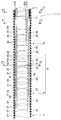
以下、図1-図8を参照して本発明の一実施形態を説明する。
図1に示すように内視鏡1は、挿入部2と、操作部3と、ユニバーサルコード4とを備えて構成されている。ユニバーサルコード4は、操作部3の側部から延出されており、その延出端にはコネクター5が設けられている。コネクター5は、制御装置および照明装置等の外部装置に電気的に接続される。 Hereinafter, an embodiment of the present invention will be described with reference to FIGS.
As shown in FIG. 1, theendoscope 1 includes an insertion portion 2, an operation portion 3, and a universal cord 4. The universal cord 4 is extended from the side part of the operation part 3, and the connector 5 is provided in the extension end. The connector 5 is electrically connected to an external device such as a control device and a lighting device.
図1に示すように内視鏡1は、挿入部2と、操作部3と、ユニバーサルコード4とを備えて構成されている。ユニバーサルコード4は、操作部3の側部から延出されており、その延出端にはコネクター5が設けられている。コネクター5は、制御装置および照明装置等の外部装置に電気的に接続される。 Hereinafter, an embodiment of the present invention will be described with reference to FIGS.
As shown in FIG. 1, the
本実施形態において、操作部3には、湾曲部操作装置6および湾曲部湾曲形状切替装置(以下、湾曲形状切替装置と略記する)9が主に設けられている。湾曲形状切替装置9は、挿入部2の軸回りに回転する操作リング9aを備えている。
In the present embodiment, the operation section 3 is mainly provided with a bending portion operation device 6 and a bending portion bending shape switching device (hereinafter abbreviated as a bending shape switching device) 9. The curved shape switching device 9 includes an operation ring 9 a that rotates about the axis of the insertion portion 2.
湾曲部操作装置6は、挿入部2が有する湾曲部(後述する符号12参照)を湾曲動作させる操作を行うための装置である。本実施形態において、湾曲部操作装置6は、上下湾曲操作ノブ(以下、上下ノブと略記する)7と、左右湾曲操作ノブ(以下、左右ノブと略記する)8とを備えている。上下ノブ7および左右ノブ8は、図示しない軸の軸回りに回動自在であり、図1中においては時計方向或いは反時計方向に回転される構成である。
The bending portion operating device 6 is a device for performing an operation of bending the bending portion (see reference numeral 12 described later) of the insertion portion 2. In the present embodiment, the bending portion operating device 6 includes an up / down bending operation knob (hereinafter abbreviated as an up / down knob) 7 and a left / right bending operation knob (hereinafter abbreviated as a left / right knob) 8. The up / down knob 7 and the left / right knob 8 are rotatable around an axis (not shown), and are configured to rotate clockwise or counterclockwise in FIG.
図1、図2に示すように挿入部2は、先端側から順に先端部11、湾曲部12、および可撓管部13を連設して構成されている。操作部3は、挿入部2の基端側に連設されている。
先端部11には観察光学系が設けられている。観察光学系は、観察部位を照明する図示しない照明ユニットおよび照明ユニットに照明された観察部位を撮像する撮像ユニット(不図示)を備えて構成されている。 As shown in FIGS. 1 and 2, theinsertion portion 2 is configured by connecting a distal end portion 11, a bending portion 12, and a flexible tube portion 13 in order from the distal end side. The operation unit 3 is connected to the proximal end side of the insertion unit 2.
Thedistal end portion 11 is provided with an observation optical system. The observation optical system includes an illumination unit (not shown) that illuminates the observation site and an imaging unit (not shown) that images the observation site illuminated by the illumination unit.
先端部11には観察光学系が設けられている。観察光学系は、観察部位を照明する図示しない照明ユニットおよび照明ユニットに照明された観察部位を撮像する撮像ユニット(不図示)を備えて構成されている。 As shown in FIGS. 1 and 2, the
The
本実施形態の湾曲部12は、第1湾曲部位14と、第2湾曲部位15と、連結駒16とを備えて構成されている。即ち、湾曲部12は、第1湾曲部位14と、第2湾曲部位15とに二分割されている。第1湾曲部位14は、湾曲部12の先端側を構成する。第2湾曲部位15は、第1湾曲部位14の基端側に連設されて、湾曲部12の基端側を構成する。 第1湾曲部位14は、複数の湾曲駒21等を回動自在に連結して、上下左右の四方向に湾曲するように構成されている。また、第2湾曲部位15は、複数の湾曲駒22等を回動自在に連結して、上下左右の四方向に湾曲するように構成されている。第1湾曲部位14を構成する湾曲駒21と、第2湾曲部位15を構成する湾曲駒22とは、同じ構成であっても、異なる構成であってもよい。
The bending portion 12 according to the present embodiment includes a first bending portion 14, a second bending portion 15, and a connecting piece 16. That is, the bending portion 12 is divided into a first bending portion 14 and a second bending portion 15. The first bending portion 14 constitutes the distal end side of the bending portion 12. The second bending portion 15 is connected to the proximal end side of the first bending portion 14 and constitutes the proximal end side of the bending portion 12. The first bending portion 14 is configured to bend in four directions, up, down, left, and right by connecting a plurality of bending pieces 21 and the like in a freely rotatable manner. The second bending portion 15 is configured to bend in four directions, up, down, left and right, by connecting a plurality of bending pieces 22 and the like in a freely rotatable manner. The bending piece 21 constituting the first bending portion 14 and the bending piece 22 constituting the second bending portion 15 may have the same configuration or different configurations.
第1湾曲部位14は、先端湾曲駒21fと、複数の湾曲駒21と、連結駒16とを回動自在に連結して上下左右の四方向に湾曲する構成である。先端湾曲駒21fは、湾曲部12の最先端及び第1湾曲部位先端を構成する。連結駒16は、第1湾曲部位基端を構成する。
The first bending portion 14 is configured to bend in four directions, up, down, left, and right by rotatably connecting the tip bending piece 21f, the plurality of bending pieces 21, and the connecting piece 16. The tip bending piece 21f constitutes the tip of the bending portion 12 and the tip of the first bending portion. The connecting piece 16 constitutes the first curved portion proximal end.
一方、第2湾曲部位15は、連結駒16と、複数の湾曲駒22と、基端湾曲駒22eとを回動自在に連結して上下左右の四方向に湾曲する構成である。連結駒16は、第2湾曲部位先端を構成する。基端湾曲駒22eは、湾曲部12の最基端及び第2湾曲部位基端を構成する。
On the other hand, the second bending portion 15 has a configuration in which the connecting piece 16, the plurality of bending pieces 22, and the base end bending piece 22e are rotatably connected to bend in four directions, up, down, left, and right. The connecting piece 16 constitutes the distal end of the second curved portion. The proximal end bending piece 22e constitutes the most proximal end of the bending portion 12 and the second curved portion proximal end.
この構成において、連結駒16は、第1湾曲部位14の基端湾曲駒と、第2湾曲部位15の先端湾曲駒とを兼用している。
In this configuration, the connecting piece 16 serves as both the proximal bending piece of the first bending portion 14 and the distal bending piece of the second bending portion 15.
可撓管部13は、軟性で且つ可撓性を有する。基端湾曲駒22eは、可撓管部13の先端側に固設された連結口金17に連結されている。
The flexible tube portion 13 is soft and flexible. The proximal bending piece 22e is connected to a connection base 17 fixed on the distal end side of the flexible tube portion 13.
図2-図5に示すように挿入部2内には、湾曲部12を上下左右方向の四方向に湾曲させる四本の湾曲ワイヤー18、後述する三本の湾曲形状切替ワイヤー19、撮像ケーブル33、2つのライトガイド34、35、処置具挿通チャンネルチューブ(以下、処置具チャンネルと略記する)36、及び送気送水チューブ37が挿通している。
As shown in FIGS. 2 to 5, in the insertion portion 2, four bending wires 18 that bend the bending portion 12 in four directions, up and down, left and right, three bending shape switching wires 19 to be described later, and an imaging cable 33. Two light guides 34, 35, a treatment instrument insertion channel tube (hereinafter abbreviated as a treatment instrument channel) 36, and an air / water supply tube 37 are inserted therethrough.
四本の湾曲ワイヤー18は、後述する四本の第1ガイドパイプ31内にそれぞれ進退自在に挿通されている。四本の第1ガイドパイプ31は、それぞれ湾曲方向に対応する。また、三本の湾曲形状切替ワイヤー19は、後述する三本の第2ガイドパイプ32内にそれぞれ進退自在に挿通されている。
The four bending wires 18 are respectively inserted into four first guide pipes 31 described later so as to freely advance and retract. The four first guide pipes 31 respectively correspond to the bending direction. Further, the three curved shape switching wires 19 are inserted into three second guide pipes 32, which will be described later, so as to freely advance and retract.
なお、図2においては図面を簡略化するため撮像ケーブル33、ライトガイド34、35、処置具チャンネル36、及び送気送水チューブ37は不図示である。また、四本の湾曲ワイヤー18では2本の湾曲ワイヤー18を図示し、三本の湾曲形状切替ワイヤー19では1本の湾曲形状切替ワイヤーを図示している。
In FIG. 2, the imaging cable 33, the light guides 34 and 35, the treatment instrument channel 36, and the air / water supply tube 37 are not shown in order to simplify the drawing. The four bending wires 18 illustrate two bending wires 18, and the three bending shape switching wires 19 illustrate one bending shape switching wire.
また、図3-図5において撮像ケーブル33、ライトガイド34、35、処置具チャンネル36及び送気送水チューブ37は、挿入部2に挿通される内蔵物であり、二点鎖線で示している。
3 to 5, the imaging cable 33, the light guides 34 and 35, the treatment instrument channel 36, and the air / water supply tube 37 are built-in objects that are inserted through the insertion portion 2, and are indicated by two-dot chain lines.
処置具チャンネル36は、把持鉗子、電気メス等の処置具を例えば体内に導入するための管路である。処置具チャンネル36は、内径寸法が大径であることが望まれている。本実施形態において、処置具チャンネル36は、外径が最も大きな内蔵物である。
The treatment instrument channel 36 is a conduit for introducing a treatment instrument such as a grasping forceps or an electric knife into the body, for example. The treatment instrument channel 36 is desired to have a large inner diameter. In the present embodiment, the treatment instrument channel 36 is a built-in object having the largest outer diameter.
図2、図5に示すように4本の第1ガイドパイプ31は、湾曲部12の四つの湾曲方向に対応する位置であって、可撓管部13の内周面の予め定められた位置に配設されている。具体的に、4本の第1ガイドパイプ31は、周方向に予め定めた間隔、例えば等間隔で可撓管部13の内周面に設けられている。
As shown in FIGS. 2 and 5, the four first guide pipes 31 are positions corresponding to the four bending directions of the bending portion 12, and are predetermined positions on the inner peripheral surface of the flexible tube portion 13. It is arranged. Specifically, the four first guide pipes 31 are provided on the inner peripheral surface of the flexible tube portion 13 at a predetermined interval in the circumferential direction, for example, at equal intervals.
そして、4つの第1ガイドパイプ31のそれぞれの先端は、連結口金17の予め定められた位置に固定され、それぞれの基端は操作部3内の図示しない予め定められた位置に固定されている。
The distal ends of the four first guide pipes 31 are fixed at predetermined positions of the connection cap 17, and the respective proximal ends are fixed at predetermined positions (not shown) in the operation unit 3. .
各湾曲ワイヤー18は、第1ガイドパイプ31内に挿通されている。湾曲ワイヤー18のそれぞれの先端は、第1ガイドパイプ31の先端開口から湾曲部12内に延出され、先端湾曲駒21fの予め定めた位置に、例えば、ろう付けによって固定されている。具体的に、湾曲ワイヤー18のそれぞれ先端は、湾曲部12の四つの湾曲方向である上下左右にそれぞれ対応する位置に固定されている。
Each bending wire 18 is inserted into the first guide pipe 31. Each distal end of the bending wire 18 extends from the distal end opening of the first guide pipe 31 into the bending portion 12, and is fixed to a predetermined position of the distal bending piece 21f by, for example, brazing. Specifically, the distal ends of the bending wires 18 are fixed at positions corresponding to the upper, lower, left, and right, which are the four bending directions of the bending portion 12.
一方、湾曲ワイヤー18のそれぞれの基端は、第1ガイドパイプ31の基端開口から操作部3内に延出され、湾曲部操作装置6を構成する図示しない上下プーリーの予め定めた位置、および図示しない左右プーリーの予め定めた位置に固定されている。上下プーリーは、上下ノブ7に一体に構成され、左右プーリーは左右ノブ8に一体に構成されている。
On the other hand, each base end of the bending wire 18 extends from the base end opening of the first guide pipe 31 into the operation unit 3, and a predetermined position of an upper and lower pulley (not shown) constituting the bending unit operation device 6, and The left and right pulleys (not shown) are fixed at predetermined positions. The upper and lower pulleys are configured integrally with the upper and lower knobs 7, and the left and right pulleys are configured integrally with the left and right knobs 8.
図3-図5中において、矢印YU方向は、湾曲部12の湾曲方向の一つである第1方向(上方向)を示し、矢印YD方向は、上方向とは逆方向であって湾曲部12の湾曲方向の一つである第2方向(下方向)を示している。図3-図5中において、矢印YL方向は、湾曲部12の湾曲方向の一つである第3方向(左方向)を示し、矢印YR方向は、左方向とは逆方向であって湾曲部12の湾曲方向の一つである第4方向(右方向)を示している。
3 to 5, the arrow YU direction indicates a first direction (upward direction) that is one of the bending directions of the bending portion 12, and the arrow YD direction is a direction opposite to the upward direction and indicates the bending portion. A second direction (downward direction), which is one of 12 bending directions, is shown. 3 to 5, the arrow YL direction indicates a third direction (left direction) that is one of the bending directions of the bending portion 12, and the arrow YR direction is the direction opposite to the left direction and is the bending portion. A fourth direction (right direction), which is one of 12 bending directions, is shown.
加えて、符号31Uは上方向第1ガイドパイプを示し、符号31Dは下方向第1ガイドパイプを示し、符号31Lは左方向第1ガイドパイプを示し、符号31Rは右方向第1ガイドパイプを示している。また、符号18Uは上方向湾曲ワイヤーを示し、符号18Dは下方向湾曲ワイヤーを示し、符号18Lは左方向湾曲ワイヤーを示し、符号18Rは右方向湾曲ワイヤーを示している。
In addition, reference numeral 31U indicates an upper first guide pipe, reference numeral 31D indicates a lower first guide pipe, reference numeral 31L indicates a left first guide pipe, and reference numeral 31R indicates a right first guide pipe. ing. Reference numeral 18U represents an upward bending wire, reference numeral 18D represents a downward bending wire, reference numeral 18L represents a left bending wire, and reference numeral 18R represents a right bending wire.
なお、図2中の符号23は、湾曲ワイヤー受けである。湾曲ワイヤー受け23は、各湾曲ワイヤー18U、18D、18L、18Rが湾曲部12内における円周方向の位置及び径方向の位置を規定する目的で、各湾曲駒21、22の内面の予め定めた位置に固設されている。
In addition, the code | symbol 23 in FIG. 2 is a curved wire receptacle. The bending wire receiver 23 has predetermined inner surfaces of the bending pieces 21 and 22 for the purpose of defining the circumferential position and the radial position of the bending wires 18U, 18D, 18L, and 18R in the bending portion 12. It is fixed in position.
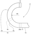
本実施形態の内視鏡1の湾曲部12は、後述する湾曲形状切替ワイヤーが非牽引状態において、上下ノブ7の操作により例えば上方向湾曲ワイヤー18Uを牽引したとき、図6に示すように予め定めた湾曲半径R1で上方向に湾曲する。この湾曲状態において、下方向湾曲ワイヤー18Dは弛緩状態である。湾曲部12は、最基端を構成する基端湾曲駒22eを起点に湾曲している。この逆に、上下ノブ7の操作により下方向湾曲ワイヤー18Dを牽引したとき、湾曲部12は、基端湾曲駒22eを起点に湾曲半径R1で下方向に湾曲する。この湾曲状態において、上方向湾曲ワイヤー18Uは、弛緩状態である。
The bending portion 12 of the endoscope 1 according to the present embodiment is preliminarily configured as shown in FIG. 6 when, for example, the upward bending wire 18U is pulled by the operation of the up / down knob 7 in a non-traction state of a bending shape switching wire described later. It bends upward with a defined radius of curvature R1. In this curved state, the downward bending wire 18D is in a relaxed state. The bending portion 12 is bent starting from a proximal bending piece 22e that constitutes the most proximal end. Conversely, when the downward bending wire 18D is pulled by operating the up / down knob 7, the bending portion 12 bends downward at the bending radius R1 with the proximal end bending piece 22e as a starting point. In this curved state, the upward bending wire 18U is in a relaxed state.
一方、内視鏡1の湾曲部12は、湾曲形状切替ワイヤーが非牽引状態において、左右ノブ8の操作により例えば左方向湾曲ワイヤー18Lを牽引したとき、基端湾曲駒22eを起点に湾曲半径R1で左方向に湾曲する。この湾曲状態において、右方向湾曲ワイヤー18Rは、弛緩状態である。この逆に、左右ノブ8の操作により右方向湾曲ワイヤー18Rを牽引したとき、湾曲部12は、基端湾曲駒22eを起点に湾曲半径R1で右方向に湾曲する。この湾曲状態において、左方向湾曲ワイヤー18Lは、弛緩状態である。
On the other hand, the bending portion 12 of the endoscope 1 has a bending radius R1 starting from the proximal bending piece 22e when, for example, the left bending wire 18L is pulled by operating the left and right knobs 8 when the bending shape switching wire is not pulled. To the left. In this curved state, the right-direction bending wire 18R is in a relaxed state. Conversely, when the right bending wire 18R is pulled by operating the left and right knob 8, the bending portion 12 bends to the right with the bending radius R1 starting from the proximal bending piece 22e. In this curved state, the left-direction bending wire 18L is in a relaxed state.
つまり、後述する湾曲形状切替ワイヤー非牽引状態において、湾曲部12は、上下ノブ7、或いは左右ノブ8の操作に伴って、湾曲部12が備える第2湾曲部位15及び第1湾曲部位14が一体で上下左右の何れかの方向に湾曲する。
That is, in the bending shape switching wire non-traction state described later, the bending portion 12 is integrated with the second bending portion 15 and the first bending portion 14 included in the bending portion 12 in accordance with the operation of the up / down knob 7 or the left / right knob 8. To bend in any direction of up, down, left and right.
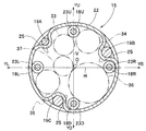
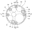
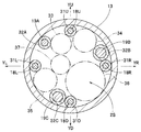
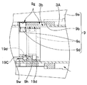
図2、図5に示すように三つの第2ガイドパイプ32は、挿入部2内に挿通される複数の内蔵物の挿通位置を考慮して可撓管部13の内周面に配置される。具体的に、3つの第2ガイドパイプ32の周方向の配置位置は、内蔵物のうち最も外径が大きな処置具チャンネル36の配置位置を踏まえて決定される。
As shown in FIGS. 2 and 5, the three second guide pipes 32 are arranged on the inner peripheral surface of the flexible tube portion 13 in consideration of the insertion positions of a plurality of built-in objects inserted into the insertion portion 2. . Specifically, the arrangement positions in the circumferential direction of the three second guide pipes 32 are determined based on the arrangement position of the treatment instrument channel 36 having the largest outer diameter among the built-in objects.
具体的に、三つの第2ガイドパイプ32のうち二つは、挿入部2内に処置具チャンネル36を配置するための最も広い最大内蔵物挿通空間2Sを形成すべく、配置される。即ち、二つの第2ガイドパイプ32のうち一方である第2ガイドパイプ32は、右方向第1ガイドパイプ31RのYU側であって、該右方向第1ガイドパイプ31Rの外周面に当接して配置される。一方、第2ガイドパイプ32うち他方である第2ガイドパイプ32は、下方向第1ガイドパイプ31DのYL側であって、該下方向第1ガイドパイプ31Dの外周面に当接して配置される。この結果、右方向第1ガイドパイプ31Rと下方向第1ガイドパイプ31Dとの間に、処置具チャンネル36を配置するための最大内蔵物挿通空間2Sが形成される。
Specifically, two of the three second guide pipes 32 are arranged to form the widest maximum built-in object insertion space 2S for arranging the treatment instrument channel 36 in the insertion portion 2. That is, the second guide pipe 32 which is one of the two second guide pipes 32 is on the YU side of the right first guide pipe 31R and abuts on the outer peripheral surface of the right first guide pipe 31R. Be placed. On the other hand, the second guide pipe 32, which is the other of the second guide pipes 32, is arranged on the YL side of the lower first guide pipe 31D and in contact with the outer peripheral surface of the lower first guide pipe 31D. . As a result, a maximum built-in object insertion space 2S for arranging the treatment instrument channel 36 is formed between the right first guide pipe 31R and the lower first guide pipe 31D.
そして、三つの第2ガイドパイプ32のうち残りの一つを、左方向第1ガイドパイプ31L及び上方向第1ガイドパイプ31Uの内側に配置する。具体的に、残りの一つ第2ガイドパイプ32を、右方向第1ガイドパイプ31Rと下方向第1ガイドパイプ31Dとの間に配置された処置具チャンネル36に対向した位置に配置する。
The remaining one of the three second guide pipes 32 is disposed inside the left first guide pipe 31L and the upper first guide pipe 31U. Specifically, the remaining one second guide pipe 32 is arranged at a position facing the treatment instrument channel 36 arranged between the right first guide pipe 31R and the lower first guide pipe 31D.
3つの第2ガイドパイプ32のそれぞれの先端は、連結口金17の予め定められた位置に固定され、それぞれの基端は操作部3内の図示しない予め定められた位置に固定されている。
Each distal end of each of the three second guide pipes 32 is fixed at a predetermined position of the connection base 17, and each base end is fixed at a predetermined position (not shown) in the operation unit 3.
各湾曲形状切替ワイヤー19は、それぞれ第2ガイドパイプ32内に挿通されている。湾曲形状切替ワイヤー19のそれぞれの先端は、第2ガイドパイプ32の先端開口から湾曲部12内に延出され、連結駒16の予め定めた位置に、例えばろう付けによって固定されている。一方、各湾曲形状切替ワイヤー19の基端は、第2ガイドパイプ32の基端から操作部3内に延出され、湾曲形状切替装置9の予め定めた位置に固定されている。
Each curved shape switching wire 19 is inserted into the second guide pipe 32. Each distal end of the curved shape switching wire 19 extends from the distal end opening of the second guide pipe 32 into the curved portion 12 and is fixed to a predetermined position of the connecting piece 16 by, for example, brazing. On the other hand, the proximal end of each curved shape switching wire 19 extends from the proximal end of the second guide pipe 32 into the operation unit 3 and is fixed to a predetermined position of the curved shape switching device 9.
第2ガイドパイプ32にそれぞれ挿通される湾曲形状切替ワイヤー19は、引張強さが異なっている。そのため、本実施形態においては、符号19A、19B、19Cを付して湾曲形状切替ワイヤーをそれぞれ区別している。
The curved shape switching wires 19 inserted through the second guide pipes 32 have different tensile strengths. For this reason, in the present embodiment, reference numerals 19A, 19B, and 19C are assigned to distinguish the curved shape switching wires.
本実施形態において、湾曲形状切替ワイヤー19B、19Cの引張強さは、湾曲形状切替ワイヤー19Aの引張強さよりも予め強く設定され、且つ、1本の湾曲形状切替ワイヤー19B、及び1本の湾曲形状切替ワイヤー19Cは、後述する第2湾曲部位15の硬化状態を保持可能な引張強さを有している。
本実施形態において、湾曲形状切替ワイヤー19Aと、湾曲形状切替ワイヤー19B、19Cとが同材質の場合、直径寸法が異なる。そして、湾曲形状切替ワイヤー19B、19Cのそれぞれの直径は、湾曲形状切替ワイヤー19Aの直径より太径にして、引張強さを大きく設定している。 In this embodiment, the tensile strength of the curved shape switching wires 19B and 19C is set in advance stronger than the tensile strength of the curved shape switching wire 19A, and one curved shape switching wire 19B and one curved shape are set. The switching wire 19 </ b> C has a tensile strength that can maintain a cured state of the second curved portion 15 described later.
In this embodiment, when the curvedshape switching wire 19A and the curved shape switching wires 19B and 19C are made of the same material, the diameter dimensions are different. The diameters of the curved shape switching wires 19B and 19C are larger than the diameter of the curved shape switching wire 19A, and the tensile strength is set to be large.
本実施形態において、湾曲形状切替ワイヤー19Aと、湾曲形状切替ワイヤー19B、19Cとが同材質の場合、直径寸法が異なる。そして、湾曲形状切替ワイヤー19B、19Cのそれぞれの直径は、湾曲形状切替ワイヤー19Aの直径より太径にして、引張強さを大きく設定している。 In this embodiment, the tensile strength of the curved
In this embodiment, when the curved
そして、湾曲形状切替ワイヤー19A、19B、19Cの径寸法が異なるため、3つの第2ガイドパイプ32に、それぞれ符号32A、32B、32Cを付して区別している。つまり、湾曲形状切替ワイヤー19Cは、第2ガイドパイプ32Cに挿通され、湾曲形状切替ワイヤー19Bは第2ガイドパイプ32Bに挿通され、湾曲形状切替ワイヤー19Aは第2ガイドパイプ32Aに挿通される。
Further, since the diameters of the curved shape switching wires 19A, 19B, and 19C are different, the three second guide pipes 32 are distinguished from each other by being provided with reference numerals 32A, 32B, and 32C, respectively. That is, the curved shape switching wire 19C is inserted through the second guide pipe 32C, the curved shape switching wire 19B is inserted through the second guide pipe 32B, and the curved shape switching wire 19A is inserted through the second guide pipe 32A.
なお、湾曲形状切替ワイヤーの引張強さを、ワイヤー直径を変化させることなく、ヤング率が異なる湾曲形状切替ワイヤーを用いて変化させるようにしてもよい。また、湾曲形状切替ワイヤー19Aも、予め定めた引張強さ以上に設定されている。具体的に、2つの湾曲形状切替ワイヤー19A、19Cによって第2湾曲部位15の硬化状態を保持すること、および2つの湾曲形状切替ワイヤー19A、19Bによって第2湾曲部位15の硬化状態を保持することが可能となる引張強さである。
Note that the tensile strength of the curved shape switching wire may be changed using curved shape switching wires having different Young's moduli without changing the wire diameter. The curved shape switching wire 19A is also set to have a predetermined tensile strength or more. Specifically, the cured state of the second curved portion 15 is held by the two curved shape switching wires 19A and 19C, and the cured state of the second curved portion 15 is held by the two curved shape switching wires 19A and 19B. Is the tensile strength at which
ここで、湾曲形状切替ワイヤー19A、19B、19Cの基端が配置される湾曲形状切替装置9について説明する。
図7に示すように湾曲形状切替装置9は、操作リング9aと、カムリング9bと、移動リング9cと、カムピン9dとを備えて主に構成されている。湾曲形状切替ワイヤー19A、19B、19Cの基端には予めストッパー19dが固設されている。
なお、図7においては図面を簡略化するため、3本の湾曲形状切替ワイヤー19A、19B、19Cのうちの1本を図示している。 Here, the curvedshape switching device 9 in which the proximal ends of the curved shape switching wires 19A, 19B, and 19C are arranged will be described.
As shown in FIG. 7, the curvedshape switching device 9 mainly includes an operation ring 9a, a cam ring 9b, a moving ring 9c, and a cam pin 9d. A stopper 19d is fixed in advance to the base ends of the curved shape switching wires 19A, 19B, and 19C.
In FIG. 7, for simplification of the drawing, one of the three curved shape switching wires 19A, 19B, 19C is shown.
図7に示すように湾曲形状切替装置9は、操作リング9aと、カムリング9bと、移動リング9cと、カムピン9dとを備えて主に構成されている。湾曲形状切替ワイヤー19A、19B、19Cの基端には予めストッパー19dが固設されている。
なお、図7においては図面を簡略化するため、3本の湾曲形状切替ワイヤー19A、19B、19Cのうちの1本を図示している。 Here, the curved
As shown in FIG. 7, the curved
In FIG. 7, for simplification of the drawing, one of the three curved
操作リング9aは、操作部先端部3Aの外周面側の予め定められた位置で操作部長手軸回りに回動するように構成されている。即ち、操作リング9aは、ユーザーによって把持されて、該長手軸を中心に時計方向、或いは反時計方向に回転される構成である。
The operation ring 9a is configured to rotate about the operation unit longitudinal axis at a predetermined position on the outer peripheral surface side of the operation unit tip 3A. That is, the operation ring 9a is configured to be gripped by the user and rotated clockwise or counterclockwise about the longitudinal axis.
カムリング9bは、操作リング9aの内周面内に配置され、操作部先端部3Aの外周面に摺動自在に配置される。カムリング9bは、操作リング9aの回転に伴って操作部3を長手軸方向に進退するように構成されている。カムリング9bには予め定めた形状の溝カム9gが形成されている。
The cam ring 9b is disposed in the inner peripheral surface of the operation ring 9a, and is slidably disposed on the outer peripheral surface of the operation portion tip portion 3A. The cam ring 9b is configured to advance and retract the operation unit 3 in the longitudinal axis direction as the operation ring 9a rotates. A groove cam 9g having a predetermined shape is formed on the cam ring 9b.
移動リング9cは、操作部3内を摺動するように配置されている。具体的に、移動リング9cは、カムリング9bの内周面側であって、操作部先端部3A内において摺動するように配置されている。移動リング9cの予め定めた位置には、外周方向に突出するカムピン9dが固設されている。カムピン9dの突端部は、操作部先端部3Aに予め形成されている長孔3bを通過して、カムリング9bの溝カム9g内に配置されている。
The moving ring 9c is arranged to slide in the operation unit 3. Specifically, the moving ring 9c is disposed on the inner peripheral surface side of the cam ring 9b so as to slide in the operation portion distal end portion 3A. A cam pin 9d protruding in the outer peripheral direction is fixed at a predetermined position of the moving ring 9c. The protruding end portion of the cam pin 9d passes through a long hole 3b formed in advance in the operation portion distal end portion 3A and is disposed in the groove cam 9g of the cam ring 9b.
符号9hはストッパー収容穴であり、ストッパー19dが収容される。ストッパー収容穴9hは、湾曲形状切替ワイヤー19A、19B、19Cの基端部の円周方向位置を規定する目的で、移動リング9cの基端面の予め定めた位置に形成されている。符号9wは軸方向貫通孔であり、湾曲形状切替ワイヤーが挿通される。ストッパー収容穴9hの中心軸と軸方向貫通孔9wの中心軸とは同軸である。
Numeral 9h is a stopper accommodating hole for accommodating the stopper 19d. The stopper accommodating hole 9h is formed at a predetermined position on the proximal end surface of the moving ring 9c for the purpose of defining the circumferential position of the proximal end portion of the curved shape switching wires 19A, 19B, 19C. Reference numeral 9w denotes an axial through hole through which a curved shape switching wire is inserted. The central axis of the stopper accommodating hole 9h and the central axis of the axial through hole 9w are coaxial.
この構成によれば、操作リング9aが例えば時計方向に回転されると、この回転に伴ってカムリング9bが操作部3の長手方向基端側に移動されていく。カムリング9bの移動に伴って、カムピン9dが溝カム9g内を移動し、該ピン9dの移動に伴って移動リング9cが操作部3の長手方向基端側に移動していく。この結果、移動リング9cは、実線に示す位置から破線に示す位置に後退される。したがって、湾曲形状切替ワイヤー19A、19B、19Cの基端に固設されている各ストッパー19dが同時に実線に示すように後退される。
According to this configuration, when the operation ring 9a is rotated in the clockwise direction, for example, the cam ring 9b is moved to the longitudinal base end side of the operation unit 3 along with the rotation. As the cam ring 9b moves, the cam pin 9d moves in the groove cam 9g, and as the pin 9d moves, the moving ring 9c moves toward the longitudinal base end side of the operation portion 3. As a result, the moving ring 9c is retracted from the position indicated by the solid line to the position indicated by the broken line. Accordingly, the stoppers 19d fixed to the base ends of the curved shape switching wires 19A, 19B, and 19C are simultaneously retracted as indicated by solid lines.
各ストッパー19dの後退に伴って、湾曲形状切替ワイヤー19A、19B、19Cの張力が同時に増大される。本実施形態において、湾曲形状切替ワイヤー19A、19B、19Cの先端は、第2湾曲部位15の先端湾曲駒である連結駒16に固定されている。このため、湾曲形状切替ワイヤー19A、19B、19Cが牽引されることにより、該ワイヤー19A、19B、19Cの張力が同時に増大されて突っ張った状態になる。すると、第2湾曲部位15を構成する複数の湾曲駒22同士が挿入部軸方向に圧縮される。この結果、第2湾曲部位15は、湾曲自在な状態から硬化状態に変化する。
As the stoppers 19d retreat, the tensions of the curved shape switching wires 19A, 19B, 19C are increased simultaneously. In the present embodiment, the distal ends of the curved shape switching wires 19 </ b> A, 19 </ b> B, and 19 </ b> C are fixed to the connecting piece 16 that is the distal bending piece of the second bending portion 15. For this reason, when the curved shape switching wires 19A, 19B, and 19C are pulled, the tension of the wires 19A, 19B, and 19C is simultaneously increased and stretched. Then, the plurality of bending pieces 22 constituting the second bending portion 15 are compressed in the insertion portion axial direction. As a result, the second bending portion 15 changes from a bendable state to a cured state.
第2湾曲部位15が硬化状態のとき、本実施形態の湾曲部12を構成する第1湾曲部位14は、湾曲自在な状態である。
When the second bending portion 15 is in a cured state, the first bending portion 14 constituting the bending portion 12 of the present embodiment is in a bendable state.
本実施形態において、内視鏡1の湾曲形状切替装置9の操作によって第2湾曲部位15を硬化状態にして、上下ノブ7の操作により例えば上方向湾曲ワイヤー18Uを牽引する。すると、湾曲部12の第1湾曲部位14は、この第1湾曲部位14の最基端を構成する連結駒16を起点に、上方向に湾曲されていく。
In the present embodiment, the second bending portion 15 is cured by operating the bending shape switching device 9 of the endoscope 1, and for example, the upward bending wire 18 </ b> U is pulled by operating the up / down knob 7. Then, the first bending portion 14 of the bending portion 12 is bent upward from the connecting piece 16 constituting the most proximal end of the first bending portion 14.
図3に示すように湾曲形状切替ワイヤー19Cは、上方向湾曲ワイヤー18Uに対して略対向する位置、言い換えれば、湾曲形状切替ワイヤー19Cと上方向湾曲ワイヤー18Uとは中心点Oを挟んで略点対称な位置、すなわち、当該ワイヤー19Cから周方向に対して略180度位置ずれした位置に上方向湾曲ワイヤー18Uが配置されている。この構成によれば、第2湾曲部位15が硬化状態において、第1湾曲部位14が上方向に湾曲されていくとき、中心点Oを通過する水平線Hで分割された挿入部上空間に配置された湾曲形状切替ワイヤー19A、19Bよりも挿入部下空間に配置された湾曲形状切替ワイヤー19Cに大きな張力がかかる。
As shown in FIG. 3, the bending shape switching wire 19 </ b> C is positioned substantially opposite to the upward bending wire 18 </ b> U, in other words, the bending shape switching wire 19 </ b> C and the upward bending wire 18 </ b> U are substantially points across the center point O. The upward bending wire 18U is disposed at a symmetric position, that is, a position displaced from the wire 19C by approximately 180 degrees with respect to the circumferential direction. According to this configuration, when the second bending portion 15 is in the cured state, the first bending portion 14 is arranged in the upper space of the insertion portion divided by the horizontal line H passing through the center point O when the first bending portion 14 is bent upward. The bending shape switching wire 19C disposed in the space below the insertion portion is more tensioned than the bending shape switching wires 19A and 19B.
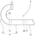
しかし、上述したように湾曲形状切替ワイヤー19Cの引張強さは、第2湾曲部位15の硬化状態を保持可能に設定されている。したがって、1本の湾曲形状切替ワイヤー19Cが、第2湾曲部位15の硬化状態を保持して、第1湾曲部位14だけが上方向に湾曲する。この結果、湾曲部12は、図8に示すように第1湾曲部位14が湾曲半径R1よりも小さな予め定めた湾曲半径R2で上方向に湾曲する。
However, as described above, the tensile strength of the curved shape switching wire 19C is set so that the cured state of the second curved portion 15 can be maintained. Accordingly, the single bending shape switching wire 19 </ b> C maintains the cured state of the second bending portion 15, and only the first bending portion 14 is bent upward. As a result, as shown in FIG. 8, in the bending portion 12, the first bending portion 14 is bent upward at a predetermined bending radius R2 smaller than the bending radius R1.
一方、本実施形態において、上述したように湾曲形状切替装置9の操作によって第2湾曲部位15を硬化状態にして、左右ノブ8の操作により例えば左方向湾曲ワイヤー18Lを牽引すると、第1湾曲部位14は、連結駒16を起点に、湾曲半径R2で左方向に湾曲されていく。
On the other hand, in the present embodiment, as described above, when the second bending portion 15 is cured by the operation of the bending shape switching device 9 and the left bending wire 18L is pulled by the operation of the left / right knob 8, for example, the first bending portion 14 is bent leftward from the connecting piece 16 with a bending radius R2.
この湾曲状態において、図3に示すように湾曲形状切替ワイヤー19Bは、左方向湾曲ワイヤー18Lに対して略対向する位置に配置されている。このため、第1湾曲部位14が左方向に湾曲されていくとき、中心点Oを通過する水平線Hに垂直な垂直線Vで分割された挿入部左空間に配置された湾曲形状切替ワイヤー19A、19Cよりも挿入部右空間に配置された湾曲形状切替ワイヤー19Bに大きな張力がかかる。
In this bending state, as shown in FIG. 3, the bending shape switching wire 19B is disposed at a position substantially opposite to the left bending wire 18L. For this reason, when the first curved portion 14 is curved leftward, the curved shape switching wire 19A disposed in the insertion portion left space divided by the vertical line V perpendicular to the horizontal line H passing through the center point O, Greater tension is applied to the curved shape switching wire 19B arranged in the right space of the insertion portion than 19C.
この場合、上述したように湾曲形状切替ワイヤー19Bの引張強さは、第2湾曲部位15の硬化状態を保持可能に設定されている。したがって、1本の湾曲形状切替ワイヤー19Bが、第2湾曲部位15の硬化状態を保持して、第1湾曲部位14だけが左方向に湾曲する。この結果、湾曲部12は、図8に示すように第1湾曲部位14が湾曲半径R2で左方向に湾曲する。
In this case, as described above, the tensile strength of the curved shape switching wire 19B is set so that the cured state of the second curved portion 15 can be maintained. Accordingly, one bending shape switching wire 19B maintains the cured state of the second bending portion 15, and only the first bending portion 14 is bent leftward. As a result, as shown in FIG. 8, in the bending portion 12, the first bending portion 14 is bent leftward with the bending radius R2.
なお、第2湾曲部位15が硬化状態において、上下ノブ7の操作により上述とは逆に、下方向湾曲ワイヤー18Dを牽引すると、第1湾曲部位14は、連結駒16を起点に、湾曲半径R2で下方向に湾曲されていく。
If the downward bending wire 18D is pulled by operating the up / down knob 7 while the second bending portion 15 is in the cured state, the first bending portion 14 starts from the connecting piece 16 and the bending radius R2 It will be bent downward.
すると、図3の水平線Hで分割された下方向空間内に配置された湾曲形状切替ワイヤー19Cよりも、上方向空間内に配置された2本の湾曲形状切替ワイヤー19A、19Bに大きな張力がかかる。
このとき、第2湾曲部位15の硬化状態は、上方向空間内に配置されている2本の湾曲形状切替ワイヤー19A、19Bによって保持されるので、第1湾曲部位14だけが下方向に湾曲される。この結果、湾曲部12は、湾曲半径R2で下方向に湾曲する。 Then, a larger tension is applied to the two curved shape switching wires 19A and 19B arranged in the upward space than the curved shape switching wires 19C arranged in the downward space divided by the horizontal line H in FIG. .
At this time, since the cured state of the secondcurved portion 15 is held by the two curved shape switching wires 19A and 19B arranged in the upward space, only the first curved portion 14 is bent downward. The As a result, the bending portion 12 is bent downward at the bending radius R2.
このとき、第2湾曲部位15の硬化状態は、上方向空間内に配置されている2本の湾曲形状切替ワイヤー19A、19Bによって保持されるので、第1湾曲部位14だけが下方向に湾曲される。この結果、湾曲部12は、湾曲半径R2で下方向に湾曲する。 Then, a larger tension is applied to the two curved
At this time, since the cured state of the second
一方、第2湾曲部位15を硬化させた状態において、左右ノブ8の操作により上述とは逆に、右方向湾曲ワイヤー18Rを牽引すると、第1湾曲部位14は、連結駒16を起点に、右方向に湾曲されていく。
On the other hand, when the right bending wire 18R is pulled by operating the left / right knob 8 in the state where the second bending portion 15 is hardened, the first bending portion 14 starts from the connecting piece 16 to the right. It is curved in the direction.
すると、図3の垂直線Vで分割された右空間内に配置された湾曲形状切替ワイヤー19Bよりも、左空間内に配置された2本の湾曲形状切替ワイヤー19A、19Cに大きな張力がかかる。
このとき、第2湾曲部位15の硬化状態は、左空間内に配置されている2本の湾曲形状切替ワイヤー19A、19Cによって保持されるので、第1湾曲部位14だけが右方向に湾曲される。この結果、湾曲部12は、湾曲半径R2で右方向に湾曲する。 Then, a larger tension is applied to the two curved shape switching wires 19A and 19C arranged in the left space than the curved shape switching wires 19B arranged in the right space divided by the vertical line V in FIG.
At this time, since the cured state of the secondcurved portion 15 is held by the two curved shape switching wires 19A and 19C disposed in the left space, only the first curved portion 14 is bent in the right direction. . As a result, the bending portion 12 bends to the right with the bending radius R2.
このとき、第2湾曲部位15の硬化状態は、左空間内に配置されている2本の湾曲形状切替ワイヤー19A、19Cによって保持されるので、第1湾曲部位14だけが右方向に湾曲される。この結果、湾曲部12は、湾曲半径R2で右方向に湾曲する。 Then, a larger tension is applied to the two curved
At this time, since the cured state of the second
つまり、湾曲部12は、第2湾曲部位15が硬化状態において、上下ノブ7、の操作に伴って、湾曲部12を構成する第1湾曲部位14だけが上下の何れかに湾曲半径R2で湾曲し、左右ノブ8の操作に伴って、湾曲部12を構成する第1湾曲部位14だけが左右の何れかに湾曲半径R2で湾曲する。
That is, in the bending portion 12, when the second bending portion 15 is in a hardened state, only the first bending portion 14 constituting the bending portion 12 is bent at any one of the upper and lower portions with a bending radius R2 in accordance with the operation of the up / down knob 7. As the left and right knob 8 is operated, only the first bending portion 14 constituting the bending portion 12 is bent to the left or right with a bending radius R2.
なお、上述した実施形態において、照明ユニットを2つのライトガイド34、35としている。しかし、照明ユニットは、2つのライトガイド34、35に限定されるものではなく、1つのライトガイド或いは3つ以上のライトガイドであってもよい。また、照明ユニットは、ライトガイドに限らず、LED等の発光素子であってよい。発光素子の場合、発光素子から延出する電線が内蔵物となる。
In the above-described embodiment, the lighting unit includes two light guides 34 and 35. However, the illumination unit is not limited to the two light guides 34 and 35, and may be one light guide or three or more light guides. The lighting unit is not limited to a light guide, and may be a light emitting element such as an LED. In the case of a light emitting element, an electric wire extending from the light emitting element is a built-in object.
また、上述した実施形態において、処置具チャンネル36の配置位置を右方向第1ガイドパイプ31Rと下方向第1ガイドパイプ31Dとの間としている。しかし、処置具チャンネル36の配置位置は、右方向第1ガイドパイプ31Rと下方向第1ガイドパイプ31Dとの間に限定されるものではない。つまり、第1ガイドパイプ31U、31R、31D、31Lのうち隣接する第1ガイドパイプ同士の間であれば、下方向第1ガイドパイプ31Dと左方向第1ガイドパイプ31Lとの間、或いは、左方向第1ガイドパイプ31Lと上方向第1ガイドパイプ31Uとの間、或いは、上方向第1ガイドパイプ31Uと右方向第1ガイドパイプ31Rとの間であってもよい。
そして、内視鏡は、内蔵物として処置具チャンネル36を含む構成に限定されるものではなく、処置具挿通チャンネルを不要にした構成であってもよい。 In the above-described embodiment, thetreatment instrument channel 36 is disposed between the right first guide pipe 31R and the lower first guide pipe 31D. However, the arrangement position of the treatment instrument channel 36 is not limited between the right first guide pipe 31R and the lower first guide pipe 31D. That is, if the first guide pipes 31U, 31R, 31D, 31L are adjacent to each other between the adjacent first guide pipes, the lower first guide pipe 31D and the left first guide pipe 31L, or the left It may be between the direction first guide pipe 31L and the upper first guide pipe 31U, or between the upper first guide pipe 31U and the right first guide pipe 31R.
The endoscope is not limited to the configuration including thetreatment instrument channel 36 as a built-in object, and may be configured such that the treatment instrument insertion channel is unnecessary.
そして、内視鏡は、内蔵物として処置具チャンネル36を含む構成に限定されるものではなく、処置具挿通チャンネルを不要にした構成であってもよい。 In the above-described embodiment, the
The endoscope is not limited to the configuration including the
湾曲形状切替ワイヤー受け24は、各湾曲形状切替ワイヤー19A、19B、19Cが第2湾曲部位15内における円周方向の位置及び径方向の位置を規定する目的で、各湾曲部22の内面の予め定めた位置に設けられている。各湾曲形状切替ワイヤー19A、19B、19Cの位置を湾曲形状切替ワイヤー受け24の代わりにストリングガイド(図3の符号25参照)を設けて規定するようにしてもよい。なお、湾曲形状切替ワイヤー受け24の径寸法も、第2ガイドパイプ32と同様に湾曲形状切替ワイヤー19A、19B、19Cの径寸法に対応している。
The curved shape switching wire receiver 24 is provided in advance on the inner surface of each curved portion 22 for the purpose of defining the circumferential position and the radial position of each curved shape switching wire 19A, 19B, 19C in the second curved portion 15. It is provided at a fixed position. The positions of the curved shape switching wires 19A, 19B, and 19C may be defined by providing a string guide (see reference numeral 25 in FIG. 3) instead of the curved shape switching wire receiver 24. The diameter of the curved shape switching wire receiver 24 also corresponds to the diameter of the curved shape switching wires 19A, 19B, and 19C, as with the second guide pipe 32.
また、図2中の符号26はブレードである。ブレード26は、第1湾曲部位14の外周および第2湾曲部位15の外周を覆う。符号27は湾曲ゴムである。湾曲ゴム27は、ブレード26の外周を覆う。
Moreover, the code | symbol 26 in FIG. 2 is a braid | blade. The blade 26 covers the outer periphery of the first curved portion 14 and the outer periphery of the second curved portion 15. Reference numeral 27 is a curved rubber. The curved rubber 27 covers the outer periphery of the blade 26.
また、3つの湾曲形状切替ワイヤー19A、19B、19Cの引張強さには以下の関係が設定されている。
湾曲形状切替ワイヤー19Bの引張強さ>湾曲形状切替ワイヤー19Aの引張強さ
湾曲形状切替ワイヤー19Cの引張強さ>湾曲形状切替ワイヤー19Aの引張強さ
湾曲形状切替ワイヤー19Cの引張強さ≧湾曲形状切替ワイヤー19Bの引張強さ
このように、湾曲形状切替ワイヤーの引っ張り強さを設定することにより、一般的に最も湾曲角度が大きく設定される、及び最も湾曲操作頻度の多い湾曲上方向の湾曲性能を長期にわたって確実に保持することができる。 Further, the following relationship is set for the tensile strengths of the three curved shape switching wires 19A, 19B, and 19C.
Tensile strength of curvedshape switching wire 19B> Tensile strength of curved shape switching wire 19A Tensile strength of curved shape switching wire 19C> Tensile strength of curved shape switching wire 19A Tensile strength of curved shape switching wire 19C ≧ curved shape Tensile strength of switching wire 19B
In this way, by setting the tensile strength of the bending shape switching wire, the bending angle is generally set to be the largest and the bending performance in the bending upward direction with the highest bending operation frequency is reliably maintained over a long period of time. be able to.
湾曲形状切替ワイヤー19Bの引張強さ>湾曲形状切替ワイヤー19Aの引張強さ
湾曲形状切替ワイヤー19Cの引張強さ>湾曲形状切替ワイヤー19Aの引張強さ
湾曲形状切替ワイヤー19Cの引張強さ≧湾曲形状切替ワイヤー19Bの引張強さ
このように、湾曲形状切替ワイヤーの引っ張り強さを設定することにより、一般的に最も湾曲角度が大きく設定される、及び最も湾曲操作頻度の多い湾曲上方向の湾曲性能を長期にわたって確実に保持することができる。 Further, the following relationship is set for the tensile strengths of the three curved
Tensile strength of curved
In this way, by setting the tensile strength of the bending shape switching wire, the bending angle is generally set to be the largest and the bending performance in the bending upward direction with the highest bending operation frequency is reliably maintained over a long period of time. be able to.
また、第2湾曲部位15を硬化させた状態において、操作リング9aを逆方向に回転させていくことによって、湾曲形状切替ワイヤー19A、19B、19Cの張力が同時に減少されていく。この結果、第2湾曲部位15は、硬化状態から湾曲自在な状態に復帰していく。
In the state where the second bending portion 15 is hardened, the tension of the bending shape switching wires 19A, 19B, and 19C is simultaneously reduced by rotating the operation ring 9a in the reverse direction. As a result, the second bending portion 15 returns from the cured state to the bendable state.
このように、内視鏡1の湾曲部12を第1湾曲部位14及び第2湾曲部位15によって二分割する。そして、内視鏡1の操作部3に、湾曲部12を上下方向に湾曲操作するための上下ノブ7、湾曲部を左右方向に湾曲操作するための左右ノブ8、及び第2湾曲部位15を硬化状態に変化させる湾曲形状切替装置9を設ける。また、内視鏡1の上下ノブ7及び左右ノブ8でそれぞれ牽引弛緩される上下左右方向に対応する四本の湾曲ワイヤー18の先端を湾曲部12の最先端を構成する先端湾曲駒21fに固定する。一方、内視鏡1の湾曲形状切替装置9で牽引弛緩される三本の湾曲形状切替ワイヤー19の先端を第1湾曲部位14と第2湾曲部位15とを連結すると共に、第1湾曲部位14の最基端を構成する連結駒16に固定する。
Thus, the bending portion 12 of the endoscope 1 is divided into two parts by the first bending portion 14 and the second bending portion 15. The operation unit 3 of the endoscope 1 includes an upper / lower knob 7 for bending the bending portion 12 in the up / down direction, a left / right knob 8 for bending the bending portion in the left / right direction, and a second bending portion 15. A curved shape switching device 9 for changing to a cured state is provided. Further, the tips of the four bending wires 18 corresponding to the up and down and left and right directions pulled and relaxed by the up and down knob 7 and the left and right knob 8 of the endoscope 1 are fixed to the tip bending piece 21f constituting the forefront of the bending portion 12, respectively. To do. On the other hand, the first bending portion 14 and the second bending portion 15 are connected to the distal ends of the three bending shape switching wires 19 that are pulled and relaxed by the bending shape switching device 9 of the endoscope 1. It fixes to the connection piece 16 which comprises the most proximal end.
このように構成した内視鏡1によれば、湾曲形状切替装置9の操作によって第2湾曲部位15を硬化させた後、上下ノブ7又は左右ノブ8を操作することによって、湾曲部12を構成する第1湾曲部位14だけを上方向又は下方向のいずれか、或いは左方向又は右方向の何れかに湾曲半径R2で湾曲させることができる。
According to the endoscope 1 configured as described above, the bending portion 12 is configured by operating the up / down knob 7 or the left / right knob 8 after curing the second bending portion 15 by operating the bending shape switching device 9. Only the first bending portion 14 to be bent can be bent with the bending radius R2 in either the upward direction or the downward direction, or in the left direction or the right direction.
一方、湾曲形状切替装置9を操作することなく、即ち、第2湾曲部位15が湾曲可能な状態において、上下ノブ7又は左右ノブ8を操作することによって、湾曲部12を構成する第1湾曲部位14および第2湾曲部位15を同時に上方向又は下方向のいずれか、或いは左方向又は右方向の何れかに湾曲半径R2よりも大きな湾曲半径R1で湾曲させることができる。
On the other hand, by operating the up / down knob 7 or the left / right knob 8 without operating the bending shape switching device 9, that is, in a state where the second bending portion 15 can be bent, the first bending portion constituting the bending portion 12. 14 and the second curved portion 15 can be simultaneously bent in either the upward direction or the downward direction, or in the left direction or the right direction with a bending radius R1 larger than the bending radius R2.
この結果、ユーザーは、観察部位の空間の広さ等を予め考慮して、自身の手元操作によって、湾曲部の湾曲半径を選択的に湾曲半径R1、湾曲半径R2に切り換えて、最良の操作性あるいは最良の観察性能を得られる。
As a result, the user can consider the size of the space of the observation site in advance, and by selectively switching the bending radius of the bending portion to the bending radius R1 and the bending radius R2 by his / her hand operation, the best operability is achieved. Alternatively, the best observation performance can be obtained.
また、作業者は、最も径寸法の大径な内視鏡内蔵物である処置具チャンネル36を第1ガイドパイプ31R、31Dの間に配置すること、及びこの最も大径な内視鏡内蔵物よりも細径な複数の内蔵物である撮像ケーブル33、ライトガイド34、35、および送気送水チューブ37等を挿入部2内に容易に配置することができる。
In addition, the operator arranges the treatment instrument channel 36 which is the endoscope having the largest diameter dimension between the first guide pipes 31R and 31D, and the endoscope having the largest diameter. The imaging cable 33, the light guides 34 and 35, the air / water supply tube 37, and the like, which are a plurality of built-in objects having a smaller diameter, can be easily arranged in the insertion portion 2.
これらの結果、内視鏡1の挿入部2を太径にすることなく、湾曲部12が有する上下左右の全ての湾曲方向に対して確実に湾曲部12の湾曲半径を選択的に湾曲半径R1、又は湾曲半径R2に切り換えることが可能な内視鏡1を実現することができる。
As a result, the bending radius of the bending portion 12 can be selectively selected with respect to all the upper, lower, left and right bending directions of the bending portion 12 without increasing the diameter of the insertion portion 2 of the endoscope 1. Or the endoscope 1 which can be switched to the curvature radius R2 is realizable.
なお、図9-図11を参照して湾曲形状切替装置の他の構成例を説明する。
図9は操作部に設けた湾曲形状切替ワイヤーを牽引するレバーを示す図、図10は湾曲形状切替ワイヤーを牽引する操作部内に設けられたリンク機構を説明する図、図11は図10のY11-Y11線断面である。 Note that another configuration example of the curved shape switching device will be described with reference to FIGS.
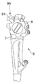
FIG. 9 is a diagram showing a lever that pulls the curved shape switching wire provided in the operation portion, FIG. 10 is a diagram illustrating a link mechanism provided in the operation portion that pulls the curved shape switching wire, and FIG. 11 is Y11 in FIG. This is a cross section taken along line -Y11.
図9は操作部に設けた湾曲形状切替ワイヤーを牽引するレバーを示す図、図10は湾曲形状切替ワイヤーを牽引する操作部内に設けられたリンク機構を説明する図、図11は図10のY11-Y11線断面である。 Note that another configuration example of the curved shape switching device will be described with reference to FIGS.
FIG. 9 is a diagram showing a lever that pulls the curved shape switching wire provided in the operation portion, FIG. 10 is a diagram illustrating a link mechanism provided in the operation portion that pulls the curved shape switching wire, and FIG. 11 is Y11 in FIG. This is a cross section taken along line -Y11.
上述した実施形態においては、湾曲形状切替装置9の操作リング9aを挿入部軸方向に
回転させて湾曲形状切替ワイヤー19A、19B、19Cを牽引して、第2湾曲部位15を硬化状態にしていた。しかし、第2湾曲部位15を硬化させる湾曲形状切替装置の構成は、この構成に限定されるものではなく、図9に示すように操作部3に設けられた上下ノブ7及び左右ノブ8の近傍に湾曲形状切替レバー(以下、レバーと略記する)91を設ける構成であってもよい。 In the above-described embodiment, theoperation ring 9a of the bending shape switching device 9 is rotated in the insertion portion axial direction, and the bending shape switching wires 19A, 19B, and 19C are pulled, and the second bending portion 15 is in a cured state. . However, the configuration of the bending shape switching device that cures the second bending portion 15 is not limited to this configuration, and the vicinity of the upper and lower knobs 7 and 8 provided in the operation unit 3 as shown in FIG. Alternatively, a curved shape switching lever (hereinafter abbreviated as a lever) 91 may be provided.
回転させて湾曲形状切替ワイヤー19A、19B、19Cを牽引して、第2湾曲部位15を硬化状態にしていた。しかし、第2湾曲部位15を硬化させる湾曲形状切替装置の構成は、この構成に限定されるものではなく、図9に示すように操作部3に設けられた上下ノブ7及び左右ノブ8の近傍に湾曲形状切替レバー(以下、レバーと略記する)91を設ける構成であってもよい。 In the above-described embodiment, the
湾曲形状切替装置9Aでは、レバー91を後述する軸を中心に時計方向或いは反時計方向に回転させることにより、湾曲形状切替ワイヤー19A、19B、19Cを牽引弛緩して、第2湾曲部位15を硬化状態、或いは湾曲自在な状態に切替可能である。
In the curved shape switching device 9A, the lever 91 is rotated clockwise or counterclockwise about an axis to be described later to pull and loosen the curved shape switching wires 19A, 19B, 19C, and the second curved portion 15 is cured. It can be switched to a state or a bendable state.
図10に示すように湾曲形状切替装置9Aは、操作軸90に対して時計方向、或いは反時計方向に回転するレバー91を備えている。レバー91の予め定めた位置には、リンク92の基端が軸支されている。リンク92の先端は、ガイド部材93内に摺動自在に配置された細長なロッド94の基端に回動自在に軸支されている。ロッド94の先端には係止部材95が固定されている。
As shown in FIG. 10, the curved shape switching device 9 </ b> A includes a lever 91 that rotates clockwise or counterclockwise with respect to the operation shaft 90. The base end of the link 92 is pivotally supported at a predetermined position of the lever 91. The distal end of the link 92 is pivotally supported by the base end of an elongated rod 94 slidably disposed in the guide member 93. A locking member 95 is fixed to the tip of the rod 94.
係止部材95には湾曲形状切替ワイヤー19A、19B、19Cが挿通される軸方向貫通孔95wが形成されている。また、湾曲形状切替ワイヤー19A、19B、19Cの基端にはストッパー19dが固設されている。
図10において図面を簡略化するため3本の湾曲形状切替ワイヤー19A、19B、19Cのうち1本を図示している。 The lockingmember 95 is formed with an axial through hole 95w through which the curved shape switching wires 19A, 19B, and 19C are inserted. In addition, a stopper 19d is fixed to the base ends of the curved shape switching wires 19A, 19B, and 19C.
In FIG. 10, one of the three curved shape switching wires 19A, 19B, and 19C is shown to simplify the drawing.
図10において図面を簡略化するため3本の湾曲形状切替ワイヤー19A、19B、19Cのうち1本を図示している。 The locking
In FIG. 10, one of the three curved
ユーザーによって、レバー91が矢印Y10方向に操作されると、リンク92によりガイド部材93内のロッド94が基端側に移動されていく。すると、ロッド94の移動に伴って、係止部材95が基端側に移動されて、湾曲形状切替ワイヤー19A、19B、19Cに固設されたストッパー19dも同時に基端側に移動される。つまり、湾曲形状切替ワイヤー19A、19B、19Cが同時に牽引される。この結果、上述した湾曲形状切替装置9と同様の作用及び効果を得ることができる。
When the lever 91 is operated in the arrow Y10 direction by the user, the rod 94 in the guide member 93 is moved to the proximal end side by the link 92. Then, as the rod 94 moves, the locking member 95 is moved to the proximal end side, and the stopper 19d fixed to the curved shape switching wires 19A, 19B, 19C is also moved to the proximal end side at the same time. That is, the curved shape switching wires 19A, 19B, 19C are pulled simultaneously. As a result, the same operation and effect as the above-described curved shape switching device 9 can be obtained.
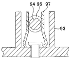
なお、図10に示すように、ロッド94の先端より予め離間した位置には凸部96が設けられている。凸部96は、レバー91が回転され、リンク92によりロッド94が例えば基端側に移動された際、ガイド部材93の先端側の内周面側に突出して設けられた、図11に示す板バネ97に対して、2点鎖線に示すようにスナップフィットによって固定される。このことにより、ロッド94の移動位置が固定され、湾曲形状切替ワイヤー19A、19B、19Cが牽引状態に保持される。
In addition, as shown in FIG. 10, the convex part 96 is provided in the position previously spaced apart from the front-end | tip of the rod 94. As shown in FIG. The convex portion 96 is provided so as to protrude to the inner peripheral surface side on the distal end side of the guide member 93 when the lever 91 is rotated and the rod 94 is moved to the proximal end side by the link 92, for example. The spring 97 is fixed by a snap fit as shown by a two-dot chain line. As a result, the moving position of the rod 94 is fixed, and the curved shape switching wires 19A, 19B, 19C are held in the pulled state.
なお、本発明は、以上述べた実施形態のみに限定されるものではなく、発明の要旨を逸脱しない範囲で種々変形実施可能である。
Note that the present invention is not limited to the above-described embodiments, and various modifications can be made without departing from the spirit of the invention.
本出願は、2011年5月20日に日本国に出願された特願2011-113903号を優先権主張の基礎として出願するものであり、上記の開示内容は、本願明細書、請求の範囲、図面に引用されたものとする。
This application is filed on the basis of the priority claim of Japanese Patent Application No. 2011-113903 filed in Japan on May 20, 2011, and the above disclosure is disclosed in the present specification, claims, It shall be cited in the drawing.
Claims (4)
- 先端に配設された先端部に観察光学系を備え、該先端部の基端側に第1方向、第2方向、第3方向、第4方向の四方向に湾曲するように構成された湾曲部を連設し、該湾曲部の基端側に軟性で且つ可撓性を有する可撓管部を連設して構成される挿入部を有し、前記挿入部内に複数の内蔵物が挿通された内視鏡において、
前記湾曲部は、
当該湾曲部の先端側を構成する複数の湾曲駒を回動自在に連結して前記四方向に湾曲する第1の湾曲部位、および、前記第1の湾曲部位の基端側に連設して該湾曲部の基端側を構成する複数の湾曲駒を回動自在に連結して前記四方向に湾曲する第2の湾曲部位を備え、
前記可撓管部内には、
当該可撓管部の内周面であって前記湾曲部の湾曲方向である四方向に対応する位置に配設された、先端が前記第1の湾曲部位の先端に固定され基端が前記挿入部の基端側に連設された操作部に設けられた湾曲部操作装置に固定される該湾曲部の湾曲方向に対応する四本の湾曲ワイヤーがそれぞれ進退自在に挿通される、四つの第1ガイドパイプと、
前記可撓管部の内周面の予め定められた位置に配設された、先端が前記第2の湾曲部位の先端に固定され、基端が前記操作部に設けられた湾曲部湾曲形状切替装置に固定される三本の湾曲形状切替ワイヤーがそれぞれ進退自在に挿通される、三つの第2ガイドパイプと、を備え、
前記内蔵物のうち、最も外径が大径な内蔵物は、前記隣接する第1ガイドパイプに当接する位置であり、
前記三つのガイドパイプのうち二つの第2ガイドパイプの周方向配置位置は、前記最も外径が大径な内蔵物に隣接する第1ガイドパイプが、最も外径が大径な内蔵物に当接している側とは反対側に当接した位置にあり、
前記三つのガイドパイプのうち残りの一つの第2ガイドパイプの周方向位置は、前記最も外径が大径な内蔵物に対向する位置にあることを特徴とする内視鏡。 A bending portion provided with an observation optical system at the distal end disposed at the distal end and configured to bend in the four directions of the first direction, the second direction, the third direction, and the fourth direction on the proximal end side of the distal end portion. A plurality of built-in objects are inserted into the insertion portion. The insertion portion includes a flexible tube portion that is flexible and flexible on the proximal end side of the bending portion. In the endoscope
The curved portion is
A plurality of bending pieces constituting the distal end side of the bending portion are rotatably connected to be connected to the first bending portion that is bent in the four directions, and the proximal end side of the first bending portion. A plurality of bending pieces constituting the proximal end side of the bending portion are rotatably connected to each other, and a second bending portion that is bent in the four directions is provided.
In the flexible tube part,
The distal end is fixed to the distal end of the first curved portion, and the proximal end is inserted into the inner peripheral surface of the flexible tube portion, corresponding to the four directions that are the bending directions of the bending portion. Four bending wires corresponding to the bending direction of the bending portion fixed to the bending portion operating device provided in the operation portion provided continuously on the proximal end side of the portion are respectively inserted into the four bending wires. 1 guide pipe,
Curved portion curve shape switching provided at a predetermined position on the inner peripheral surface of the flexible tube portion with a distal end fixed to the distal end of the second curved portion and a proximal end provided on the operation portion Three second guide pipes, through which three curved shape switching wires fixed to the device are inserted so as to freely advance and retract,
Among the built-in objects, the built-in object having the largest outer diameter is a position that comes into contact with the adjacent first guide pipe,
Of the three guide pipes, the two second guide pipes are arranged in the circumferential direction so that the first guide pipe adjacent to the built-in object having the largest outer diameter corresponds to the built-in object having the largest outer diameter. It is in a position that is in contact with the opposite side of the contact side,
The endoscope is characterized in that a circumferential position of the remaining one of the three guide pipes is a position facing the built-in object having the largest outer diameter. - 前記3本の湾曲形状切替ワイヤーのうち、前記最も外径が大径な内蔵物に隣接する第1ガイドパイプが、最も外径が大径な内蔵物に当接している側と反対側に当接した位置にある第2ガイドパイプ内に挿通された湾曲形状切替ワイヤーの引張強さを、前記最も外径が大径な内蔵物に対向する位置にある第2ガイドパイプ内に挿通された湾曲形状切替ワイヤーの引張強さより強く設定したことを特徴とする請求項1に記載の内視鏡。 Of the three curved shape switching wires, the first guide pipe adjacent to the built-in object having the largest outer diameter contacts the side opposite to the side in contact with the built-in object having the largest outer diameter. The bending strength inserted into the second guide pipe located in the second guide pipe is in contact with the tensile strength of the curved shape switching wire inserted into the second guide pipe located at the position facing the built-in object having the largest outer diameter. The endoscope according to claim 1, wherein the endoscope is set stronger than the tensile strength of the shape switching wire.
- 前記3本の湾曲形状切替ワイヤーのうち前記最も外径が大径な内蔵物に隣接する第1ガイドパイプが、最も外径が大径な内蔵物に当接している側は反対側に当接した位置にある第2ガイドパイプ内に挿通された湾曲形状切替ワイヤーの直径を、前記最も外径が大径な内蔵物に対向する位置にある第2ガイドパイプ内に挿通された湾曲形状切替ワイヤーの直径より太径に設定したことを特徴とする請求項1に記載の内視鏡。 Of the three curved shape switching wires, the first guide pipe adjacent to the built-in object having the largest outer diameter is in contact with the opposite side on the side contacting the built-in object having the largest outer diameter. The curved shape switching wire inserted into the second guide pipe at the position facing the built-in object having the largest outer diameter is set to the diameter of the curved shape switching wire inserted into the second guide pipe at the position The endoscope according to claim 1, wherein the endoscope is set to be thicker than the diameter of the endoscope.
- 前記3本の湾曲形状切替ワイヤーのうち、前記湾曲部の湾曲角度が最も大きく設定される、或いは最も湾曲操作頻度が多い湾曲方向に湾曲させる湾曲ワイヤーに対して対向する位置に設けられた湾曲形状切替ワイヤーの引張強さは、他の湾曲形状切替ワイヤーの引張強さよりも強いことを特徴とする請求項2または請求項3に記載の内視鏡。 Of the three bending shape switching wires, a bending shape provided at a position facing the bending wire in which the bending angle of the bending portion is set to the maximum or bent in the bending direction with the highest bending operation frequency. The endoscope according to claim 2 or 3, wherein the tensile strength of the switching wire is stronger than the tensile strength of other curved shape switching wires.
Priority Applications (2)
| Application Number | Priority Date | Filing Date | Title |
|---|---|---|---|
| JP2012552603A JP5253676B2 (en) | 2011-05-20 | 2012-05-14 | Endoscope |
| US13/682,355 US9173552B2 (en) | 2011-05-20 | 2012-11-20 | Endoscope |
Applications Claiming Priority (2)
| Application Number | Priority Date | Filing Date | Title |
|---|---|---|---|
| JP2011-113903 | 2011-05-20 | ||
| JP2011113903 | 2011-05-20 |
Related Child Applications (1)
| Application Number | Title | Priority Date | Filing Date |
|---|---|---|---|
| US13/682,355 Continuation US9173552B2 (en) | 2011-05-20 | 2012-11-20 | Endoscope |
Publications (1)
| Publication Number | Publication Date |
|---|---|
| WO2012161021A1 true WO2012161021A1 (en) | 2012-11-29 |
Family
ID=47217101
Family Applications (1)
| Application Number | Title | Priority Date | Filing Date |
|---|---|---|---|
| PCT/JP2012/062322 WO2012161021A1 (en) | 2011-05-20 | 2012-05-14 | Endoscope |
Country Status (3)
| Country | Link |
|---|---|
| US (1) | US9173552B2 (en) |
| JP (1) | JP5253676B2 (en) |
| WO (1) | WO2012161021A1 (en) |
Families Citing this family (10)
| Publication number | Priority date | Publication date | Assignee | Title |
|---|---|---|---|---|
| US9901410B2 (en) | 2010-07-28 | 2018-02-27 | Medrobotics Corporation | Surgical positioning and support system |
| WO2012043076A1 (en) * | 2010-09-28 | 2012-04-05 | オリンパスメディカルシステムズ株式会社 | Endoscope device |
| EP2629655B1 (en) * | 2010-10-22 | 2018-12-19 | Medrobotics Corporation | Highly articulated robotic probes and methods of production and use of such probes |
| US9649163B2 (en) | 2010-11-11 | 2017-05-16 | Medrobotics Corporation | Introduction devices for highly articulated robotic probes and methods of production and use of such probes |
| WO2013039999A2 (en) | 2011-09-13 | 2013-03-21 | Medrobotics Corporation | Highly articulated probes with anti-twist link arrangement, methods of formation thereof, and methods of performing medical procedures |
| EP3321048A4 (en) * | 2015-07-09 | 2019-03-20 | Kawasaki Jukogyo Kabushiki Kaisha | Surgical robot |
| US11559190B2 (en) | 2017-05-03 | 2023-01-24 | Canon U.S.A., Inc. | Steerable medical device and method |
| WO2020008571A1 (en) * | 2018-07-04 | 2020-01-09 | オリンパス株式会社 | Endoscope |
| WO2022067301A1 (en) * | 2020-09-25 | 2022-03-31 | Boston Scientific Scimed, Inc. | Medical imaging device |
| DE102020126239A1 (en) * | 2020-10-07 | 2022-04-07 | Hoya Corporation | Endoscope with flexible insertion tube and bending section |
Citations (8)
| Publication number | Priority date | Publication date | Assignee | Title |
|---|---|---|---|---|
| JPH02118501U (en) * | 1989-03-13 | 1990-09-25 | ||
| JPH0343802U (en) * | 1989-09-07 | 1991-04-24 | ||
| JPH1014861A (en) * | 1996-07-01 | 1998-01-20 | Olympus Optical Co Ltd | Endoscope |
| JPH1024013A (en) * | 1996-07-12 | 1998-01-27 | Olympus Optical Co Ltd | Endoscope |
| JPH10201703A (en) * | 1997-01-24 | 1998-08-04 | Olympus Optical Co Ltd | Endoscope |
| JP2002143084A (en) * | 2000-11-06 | 2002-05-21 | Olympus Optical Co Ltd | Endoscope device |
| JP2006068393A (en) * | 2004-09-03 | 2006-03-16 | Olympus Corp | Endoscope |
| WO2011114570A1 (en) * | 2010-03-15 | 2011-09-22 | オリンパスメディカルシステムズ株式会社 | Endoscope |
Family Cites Families (7)
| Publication number | Priority date | Publication date | Assignee | Title |
|---|---|---|---|---|
| JPH02118501A (en) * | 1988-10-28 | 1990-05-02 | Hitachi Ltd | Lens for projection type television |
| JPH0343802A (en) * | 1989-07-12 | 1991-02-25 | Omron Corp | Fuzzy controller |
| WO1993013704A1 (en) * | 1992-01-09 | 1993-07-22 | Endomedix Corporation | Bi-directional miniscope |
| JPH10328131A (en) * | 1997-06-04 | 1998-12-15 | Olympus Optical Co Ltd | Endoscope unit |
| JP4855867B2 (en) * | 2006-08-22 | 2012-01-18 | オリンパスメディカルシステムズ株式会社 | Endoscope |
| JP2009112537A (en) * | 2007-11-07 | 2009-05-28 | Hoya Corp | Flexible endoscope |
| JP5235773B2 (en) * | 2009-04-30 | 2013-07-10 | Hoya株式会社 | Flexible endoscope |
-
2012
- 2012-05-14 JP JP2012552603A patent/JP5253676B2/en not_active Expired - Fee Related
- 2012-05-14 WO PCT/JP2012/062322 patent/WO2012161021A1/en active Application Filing
- 2012-11-20 US US13/682,355 patent/US9173552B2/en not_active Expired - Fee Related
Patent Citations (8)
| Publication number | Priority date | Publication date | Assignee | Title |
|---|---|---|---|---|
| JPH02118501U (en) * | 1989-03-13 | 1990-09-25 | ||
| JPH0343802U (en) * | 1989-09-07 | 1991-04-24 | ||
| JPH1014861A (en) * | 1996-07-01 | 1998-01-20 | Olympus Optical Co Ltd | Endoscope |
| JPH1024013A (en) * | 1996-07-12 | 1998-01-27 | Olympus Optical Co Ltd | Endoscope |
| JPH10201703A (en) * | 1997-01-24 | 1998-08-04 | Olympus Optical Co Ltd | Endoscope |
| JP2002143084A (en) * | 2000-11-06 | 2002-05-21 | Olympus Optical Co Ltd | Endoscope device |
| JP2006068393A (en) * | 2004-09-03 | 2006-03-16 | Olympus Corp | Endoscope |
| WO2011114570A1 (en) * | 2010-03-15 | 2011-09-22 | オリンパスメディカルシステムズ株式会社 | Endoscope |
Also Published As
| Publication number | Publication date |
|---|---|
| US9173552B2 (en) | 2015-11-03 |
| JPWO2012161021A1 (en) | 2014-07-31 |
| US20130150673A1 (en) | 2013-06-13 |
| JP5253676B2 (en) | 2013-07-31 |
Similar Documents
| Publication | Publication Date | Title |
|---|---|---|
| JP5253676B2 (en) | Endoscope | |
| US9345390B2 (en) | Endoscope flexible tube and endoscope device | |
| JP4323441B2 (en) | Endoscope | |
| EP2457491B1 (en) | Endoscope | |
| WO2011145533A1 (en) | Medical device | |
| US20140296771A1 (en) | Insertion body, insertion apparatus, rotation unit and rotative force transmission unit | |
| CN104955376A (en) | Integrated steering device | |
| EP2974647A1 (en) | Endoscope | |
| US20130331651A1 (en) | Flexible tube portion of endoscope and endoscope having this flexible tube portion | |
| US20170172385A1 (en) | Endoscope | |
| US8728089B2 (en) | Endoscope treatment instrument | |
| JPWO2018029908A1 (en) | Curved tube and endoscope | |
| US20150313447A1 (en) | Insertion instrument and endoscope | |
| US9770158B2 (en) | Holding mechanism for endoscope guide member, and endoscope | |
| CN108697303B (en) | Bending operation device and endoscope | |
| WO2018070342A1 (en) | Endoscope | |
| EP3199088A1 (en) | Endoscope | |
| JP2018143583A (en) | Endoscope | |
| JP6284182B2 (en) | Operation unit for bending treatment tools | |
| WO2019150627A1 (en) | Endoscope | |
| JP3798884B2 (en) | Endoscope | |
| JPH10314106A (en) | Endoscope | |
| JP6157334B2 (en) | Insertion equipment | |
| JP6091252B2 (en) | Endoscope | |
| JP2014108171A (en) | Insertion device and endoscope |
Legal Events
| Date | Code | Title | Description |
|---|---|---|---|
| ENP | Entry into the national phase |
Ref document number: 2012552603 Country of ref document: JP Kind code of ref document: A |
|
| 121 | Ep: the epo has been informed by wipo that ep was designated in this application |
Ref document number: 12789556 Country of ref document: EP Kind code of ref document: A1 |
|
| NENP | Non-entry into the national phase |
Ref country code: DE |
|
| 122 | Ep: pct application non-entry in european phase |
Ref document number: 12789556 Country of ref document: EP Kind code of ref document: A1 |