WO2012157443A1 - Image processing apparatus and image processing method - Google Patents
Image processing apparatus and image processing method Download PDFInfo
- Publication number
- WO2012157443A1 WO2012157443A1 PCT/JP2012/061521 JP2012061521W WO2012157443A1 WO 2012157443 A1 WO2012157443 A1 WO 2012157443A1 JP 2012061521 W JP2012061521 W JP 2012061521W WO 2012157443 A1 WO2012157443 A1 WO 2012157443A1
- Authority
- WO
- WIPO (PCT)
- Prior art keywords
- image
- prediction
- unit
- color image
- encoding
- Prior art date
Links
Images


Classifications
-
- H—ELECTRICITY
- H04—ELECTRIC COMMUNICATION TECHNIQUE
- H04N—PICTORIAL COMMUNICATION, e.g. TELEVISION
- H04N19/00—Methods or arrangements for coding, decoding, compressing or decompressing digital video signals
- H04N19/50—Methods or arrangements for coding, decoding, compressing or decompressing digital video signals using predictive coding
- H04N19/597—Methods or arrangements for coding, decoding, compressing or decompressing digital video signals using predictive coding specially adapted for multi-view video sequence encoding
-
- H—ELECTRICITY
- H04—ELECTRIC COMMUNICATION TECHNIQUE
- H04N—PICTORIAL COMMUNICATION, e.g. TELEVISION
- H04N13/00—Stereoscopic video systems; Multi-view video systems; Details thereof
- H04N13/10—Processing, recording or transmission of stereoscopic or multi-view image signals
- H04N13/194—Transmission of image signals
-
- H—ELECTRICITY
- H04—ELECTRIC COMMUNICATION TECHNIQUE
- H04N—PICTORIAL COMMUNICATION, e.g. TELEVISION
- H04N19/00—Methods or arrangements for coding, decoding, compressing or decompressing digital video signals
- H04N19/50—Methods or arrangements for coding, decoding, compressing or decompressing digital video signals using predictive coding
- H04N19/59—Methods or arrangements for coding, decoding, compressing or decompressing digital video signals using predictive coding involving spatial sub-sampling or interpolation, e.g. alteration of picture size or resolution
-
- H—ELECTRICITY
- H04—ELECTRIC COMMUNICATION TECHNIQUE
- H04N—PICTORIAL COMMUNICATION, e.g. TELEVISION
- H04N19/00—Methods or arrangements for coding, decoding, compressing or decompressing digital video signals
- H04N19/70—Methods or arrangements for coding, decoding, compressing or decompressing digital video signals characterised by syntax aspects related to video coding, e.g. related to compression standards
-
- H—ELECTRICITY
- H04—ELECTRIC COMMUNICATION TECHNIQUE
- H04N—PICTORIAL COMMUNICATION, e.g. TELEVISION
- H04N19/00—Methods or arrangements for coding, decoding, compressing or decompressing digital video signals
- H04N19/50—Methods or arrangements for coding, decoding, compressing or decompressing digital video signals using predictive coding
- H04N19/503—Methods or arrangements for coding, decoding, compressing or decompressing digital video signals using predictive coding involving temporal prediction
- H04N19/51—Motion estimation or motion compensation
-
- H—ELECTRICITY
- H04—ELECTRIC COMMUNICATION TECHNIQUE
- H04N—PICTORIAL COMMUNICATION, e.g. TELEVISION
- H04N19/00—Methods or arrangements for coding, decoding, compressing or decompressing digital video signals
- H04N19/60—Methods or arrangements for coding, decoding, compressing or decompressing digital video signals using transform coding
- H04N19/61—Methods or arrangements for coding, decoding, compressing or decompressing digital video signals using transform coding in combination with predictive coding
Definitions
- the present technology relates to an image processing device and an image processing method, and an image processing device and an image processing method that can improve the prediction efficiency of parallax prediction performed in encoding and decoding of images of a plurality of viewpoints. About.
- an encoding method for encoding an image of a plurality of viewpoints such as a 3D (Dimension) image
- MVC Multiview Video Coding
- AVC Advanced Video Coding
- an image to be encoded is a color image having a value corresponding to light from a subject as a pixel value, and each of the color images of a plurality of viewpoints is, as necessary, a color image of the viewpoint.
- encoding is performed with reference to color images of other viewpoints.
- one viewpoint color image among a plurality of viewpoint color images is used as a base view image, and other viewpoint color images are used as non-base views (Non Base view). It is said that.
- the color image of the base view is encoded with reference to only the color image of the base view, and the color image of the non-base view needs the image of another view in addition to the color image of the non-base view. And is encoded according to the reference.
- parallax prediction that generates a predicted image with reference to the color image of another view (viewpoint) is performed as necessary, and is encoded using the predicted image.
- parallax prediction with reference to another viewpoint image can be performed in encoding (and decoding) of a certain viewpoint image.
- Accuracy affects the coding efficiency.
- the present technology has been made in view of such a situation, and makes it possible to improve the prediction efficiency of parallax prediction.
- the image processing device provides two viewpoints according to an encoding mode when encoding an encoding target image to be encoded among two or more viewpoint images among three or more viewpoint images.
- the above image is packed according to a packing pattern that packs the image for one viewpoint, thereby converting the packed image converted into a packed image and the packed image converted by the converting unit into the encoding target image or the reference.
- a parallax compensation is performed to generate a prediction image of the encoding target image, and the prediction image generated by the compensation unit is used to convert the encoding target image to the encoding mode.
- An image processing apparatus including an encoding unit that performs encoding with
- the image processing method is based on two viewpoints according to an encoding mode when encoding an encoding target image of two or more viewpoints among three or more viewpoint images.
- the image is converted into a packed image, and the packed image is used as the encoding target image or the reference image to perform parallax compensation,
- It is an image processing method including a step of generating a prediction image of the encoding target image and encoding the encoding target image in the encoding mode using the prediction image.
- images of two or more viewpoints among images of three or more viewpoints have two or more viewpoints according to the encoding mode when encoding the encoding target image to be encoded.
- the image is converted into a packed image.
- a prediction image of the encoding target image is generated by performing parallax compensation using the packing image as the encoding target image or a reference image, and the encoding target image is generated using the prediction image.
- the image processing apparatus provides two or more viewpoints according to an encoding mode when encoding an encoding target image of two or more viewpoints among images of viewpoints or more.
- a packing pattern that packs the image of one image into an image for one viewpoint, the image is converted into a packed image, and the packed image is used as the encoding target image or the reference image to perform parallax compensation, thereby Generating a predicted image of an encoding target image, and using the predicted image to decode an encoded stream obtained by encoding the encoding target image in the encoding mode;
- a compensator that generates a prediction image of a decoding target image by performing parallax compensation, and the prediction stream generated by the compensation unit, and the encoding stream
- the packed image is determined according to the packing pattern.
- An image processing apparatus including an inverse conversion unit that performs inverse conversion to an image of two or more original
- the image processing method is based on two viewpoints according to an encoding mode when encoding an encoding target image that is an encoding target image of two or more viewpoints among three or more viewpoint images.
- the image is converted into a packed image, and the packed image is used as the encoding target image or the reference image to perform parallax compensation,
- a prediction image of the decoding target image is generated by performing parallax compensation, and the encoded stream is decoded in the encoding mode using the prediction image,
- the step of inversely transforming the packed image into an image of two or more original viewpoints by separating the packed image according to the packing pattern is an image processing method including.
- an image of two or more viewpoints among images of three or more viewpoints is selected according to an encoding mode when encoding an encoding target image to be encoded.
- the image is converted into a packed image by packing according to a packing pattern that packs the image into an image for one viewpoint, and the packed image is converted into the encoding target image or the reference image by performing parallax compensation.
- Decoding of a decoding target which is used when a prediction image of a coding target image is generated and an encoded stream obtained by encoding the coding target image in the coding mode is decoded using the prediction image
- a predicted image of the target image is generated by performing parallax compensation.
- the encoded stream is decoded in the encoding mode using the prediction image, and the decoding target image obtained by decoding the encoded stream is the packed image, the packed image Are separated according to the packing pattern, thereby being inversely converted into an original image of two or more viewpoints.
- the image processing apparatus may be an independent apparatus or an internal block constituting one apparatus.
- the image processing apparatus can be realized by causing a computer to execute a program, and the program can be provided by being transmitted through a transmission medium or by being recorded on a recording medium.
- FIG. 3 is a block diagram illustrating a configuration example of a transmission device 11.
- FIG. 3 is a block diagram illustrating a configuration example of a receiving device 12.
- FIG. It is a figure explaining resolution conversion which resolution conversion device 21C performs.
- It is a block diagram which shows the structural example of 22C of encoding apparatuses. It is a figure explaining the picture (reference image) referred when producing
- FIG. 3 is a block diagram illustrating a configuration example of an encoder 42.
- FIG. It is a figure explaining the macroblock type of MVC (AVC). It is a figure explaining the prediction vector (PMV) of MVC (AVC).
- PMV prediction vector
- FIG. 5 is a block diagram illustrating a configuration example of a disparity prediction unit 131.
- FIG. It is a block diagram which shows the structural example of 32C of decoding apparatuses.
- 3 is a block diagram illustrating a configuration example of a decoder 212.
- FIG. It is a block diagram which shows the structural example of the inter estimation part 250.
- FIG. 5 is a block diagram illustrating a configuration example of a disparity prediction unit 261.
- FIG. 11 is a block diagram illustrating another configuration example of the transmission device 11.
- FIG. 11 is a block diagram illustrating another configuration example of the receiving device 12.
- FIG. It is a figure explaining the resolution conversion which the resolution conversion apparatus 321C performs, and the resolution reverse conversion which the resolution reverse conversion apparatus 333C performs.
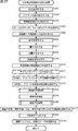
- 4 is a flowchart for explaining processing of a transmission device 11.
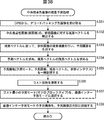
- 6 is a flowchart for explaining processing of the reception device 12.
- 3 is a block diagram illustrating a configuration example of an encoder 342.
- FIG. It is a figure explaining the resolution conversion SEI produced
- FIG. It is a figure explaining the value set to parameters num_views_minus_1, view_id [i], frame_packing_info [i], frame_field_coding, and view_id_in_frame [i]. It is a figure explaining the parallax prediction of the picture (field) of the packing color image performed in the parallax prediction part 131.
- FIG. It is a flowchart explaining the encoding process which encodes a packing color image which the encoder 342 performs. It is a flowchart explaining the parallax prediction process which the parallax prediction part 131 performs.
- 21 is a flowchart for describing a decoding process performed by a decoder 412 to decode encoded data of a packed color image. It is a flowchart explaining the parallax prediction process which the parallax prediction part 261 performs. It is a block diagram which shows the other structural example of the encoding apparatus 322C. 5 is a block diagram illustrating a configuration example of an encoder 542. FIG. It is a figure explaining the parallax prediction of the picture (field) of the central viewpoint color image performed in the parallax prediction part 131. FIG. It is a flowchart explaining the encoding process which encodes a packing color image which the encoder 542 performs.
- FIG. 11 is a block diagram illustrating still another configuration example of the transmission device 11.
- FIG. 722C shows the structural example of encoding apparatus 722C.
- FIG. 4 is a block diagram illustrating a configuration example of an encoder 842.
- FIG. It is a figure explaining parallax and depth.
- FIG. 18 is a block diagram illustrating a configuration example of an embodiment of a computer to which the present technology is applied. It is a figure which shows the schematic structural example of TV to which this technique is applied. It is a figure which shows the schematic structural example of the mobile telephone to which this technique is applied. It is a figure which shows the schematic structural example of the recording / reproducing apparatus to which this technique is applied. It is a figure which shows the schematic structural example of the imaging device to which this technique is applied.
- FIG. 46 is a diagram illustrating parallax and depth.
- the depth of the subject M from the camera c1 (camera c2).
- the depth Z that is the distance in the direction is defined by the following equation (a).
- L is a horizontal distance between the position C1 and the position C2 (hereinafter, referred to as an inter-camera distance).
- D is the position of the subject M on the color image photographed by the camera c2 from the horizontal distance u1 of the position of the subject M on the color image photographed by the camera c1 from the center of the color image.
- f is the focal length of the camera c1, and in the formula (a), the focal lengths of the camera c1 and the camera c2 are the same.
- the parallax d and the depth Z can be uniquely converted. Therefore, in this specification, the image representing the parallax d and the image representing the depth Z of the two viewpoint color images captured by the camera c1 and the camera c2 are collectively referred to as a depth image (parallax information image).
- the depth image may be an image representing the parallax d or the depth Z
- the pixel value of the depth image is not the parallax d or the depth Z itself but the parallax d as a normal value.
- the normalized value the value obtained by normalizing the reciprocal 1 / Z of the depth Z, and the like can be employed.
- the value I obtained by normalizing the parallax d with 8 bits (0 to 255) can be obtained by the following equation (b). Note that the normalization bit number of the parallax d is not limited to 8 bits, and other bit numbers such as 10 bits and 12 bits may be used.
- D max is the maximum value of the parallax d
- D min is the minimum value of the parallax d.
- the maximum value D max and the minimum value D min may be set in units of one screen, or may be set in units of a plurality of screens.
- the value y obtained by normalizing the reciprocal 1 / Z of the depth Z by 8 bits (0 to 255) can be obtained by the following equation (c).
- the normalized bit number of the inverse 1 / Z of the depth Z is not limited to 8 bits, and other bit numbers such as 10 bits and 12 bits may be used.
- Z far is the maximum value of the depth Z
- Z near is the minimum value of the depth Z.
- the maximum value Z far and the minimum value Z near may be set in units of one screen or may be set in units of a plurality of screens.
- an image having a pixel value of the value I obtained by normalizing the parallax d, and an inverse 1 / of the depth Z is collectively referred to as a depth image (parallax information image).
- a depth image parllax information image
- the color format of the depth image is YUV420 or YUV400, but other color formats are also possible.
- the value I or the value y is set as the depth information (disparity information). Further, the mapping of the value I or the value y is a depth map.
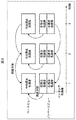
- FIG. 1 is a block diagram illustrating a configuration example of an embodiment of a transmission system to which the present technology is applied.
- the transmission system includes a transmission device 11 and a reception device 12.
- the transmission device 11 is supplied with a multi-view color image and a multi-view parallax information image (multi-view depth image).
- the multi-viewpoint color image includes color images of a plurality of viewpoints, and a color image of a predetermined one viewpoint among the plurality of viewpoints is designated as a base view image. Color images of each viewpoint other than the base view image are treated as non-base view images.
- the multi-view parallax information image includes the parallax information image of each viewpoint of the color images constituting the multi-view color image.
- a predetermined single viewpoint parallax information image is designated as the base view image.
- the parallax information image of each viewpoint other than the base view image is treated as a non-base view image as in the case of a color image.
- the transmission device 11 encodes and multiplexes each of the multi-view color image and the multi-view parallax information image supplied thereto, and outputs a multiplexed bit stream obtained as a result.
- the multiplexed bit stream output from the transmission device 11 is transmitted via a transmission medium (not shown) or recorded on a recording medium (not shown).
- the multiplexed bit stream output from the transmission device 11 is provided to the reception device 12 via a transmission medium or a recording medium (not shown).
- the receiving device 12 receives the multiplexed bit stream and performs demultiplexing of the multiplexed bit stream, thereby encoding the encoded data of the multi-view color image and the encoding of the multi-view disparity information image from the multiplexed bit stream. Separate data.
- the reception device 12 decodes each of the encoded data of the multi-view color image and the encoded data of the multi-view parallax information image, and outputs the resulting multi-view color image and multi-view parallax information image.
- a naked-eye 3D (dimension) image that can be viewed with the naked eye MPEG3DV is now being developed with the main application as a display.
- the data amount is a data amount of a full HD 2D image (one 6 times the data amount of the viewpoint image).
- HDMI High-Definition Multimedia Interface
- 4K 4 times the full HD
- the transmission device 11 encodes the multi-view color image and the multi-view disparity information image, but the bit rate of the multiplexed bit stream output from the transmission device 11 is limited.
- the bit amount of encoded data allocated to images of one viewpoint is also limited.
- the transmission device 11 performs encoding after reducing the data amount (in the baseband) of the multi-view color image and the multi-view parallax information image.
- a disparity value representing the disparity between the subject captured in each pixel of the color image and the reference viewpoint, with a certain viewpoint as a reference viewpoint.
- a depth value representing the distance (depth) to the subject appearing in each pixel of the color image can be used.
- the parallax value and the depth value can be converted into each other, and thus are equivalent information.
- a parallax information image (depth image) having a parallax value as a pixel value is also referred to as a parallax image
- a parallax information image (depth image) having a depth value as a pixel value is also referred to as a depth image.
- a depth image of the parallax image and the depth image is used as the parallax information image, but a parallax image can also be used as the parallax information image.
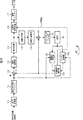
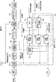
- FIG. 2 is a block diagram illustrating a configuration example of the transmission device 11 of FIG.
- the transmission device 11 includes resolution conversion devices 21C and 21D, encoding devices 22C and 22D, and a multiplexing device 23.
- the multi-viewpoint color image is supplied to the resolution conversion device 21C.
- the resolution conversion device 21C performs resolution conversion for converting the multi-view color image supplied thereto into a low-resolution resolution conversion multi-view color image lower than the original resolution, and the resulting resolution-converted multi-view color image is converted. To the encoding device 22C.
- the encoding device 22C is encoded data obtained by encoding the resolution-converted multi-viewpoint color image supplied from the resolution conversion device 21C using, for example, MVC, which is a standard for transmitting images of a plurality of viewpoints. Multi-view color image encoded data is supplied to the multiplexer 23.
- MVC is an extended profile of AVC, and according to MVC, as described above, non-base view images can be efficiently encoded with disparity prediction.
- base view images are encoded with AVC compatibility. Therefore, encoded data obtained by encoding an image of a base view with MVC can be decoded with an AVC decoder.
- the resolution conversion device 21D is supplied with a multi-view depth image that is a depth image of each viewpoint having a depth value for each pixel of the color image of each viewpoint constituting the multi-view color image as a pixel value.
- the resolution conversion device 21 ⁇ / b> D and the encoding device 22 ⁇ / b> D use a depth image (multi-view depth image) instead of a color image (multi-view color image) as a processing target, and the resolution conversion device 21 ⁇ / b> C and The same processing is performed with the encoding device 22C.
- the resolution conversion device 21D converts the resolution of the multi-view depth image supplied thereto into a low-resolution resolution conversion multi-view depth image lower than the original resolution, and supplies the converted image to the encoding device 22D.
- the encoding device 22D encodes the resolution-converted multi-view depth image supplied from the resolution conversion device 21D with MVC, and the multi-view depth image encoded data, which is encoded data obtained as a result, to the multiplexing device 23. Supply.
- the multiplexing device 23 multiplexes the multi-view color image encoded data from the encoding device 22C and the multi-view depth image encoded data from the encoding device 22D, and outputs a multiplexed bit stream obtained as a result. .
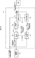
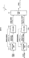
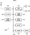
- FIG. 3 is a block diagram illustrating a configuration example of the receiving device 12 of FIG.
- the reception device 12 includes a demultiplexing device 31, decoding devices 32C and 32D, and resolution inverse conversion devices 33C and 33D.
- the demultiplexer 31 is supplied with the multiplexed bit stream output from the transmitter 11 (FIG. 2).
- the demultiplexer 31 receives the multiplexed bitstream supplied thereto, and performs demultiplexing of the multiplexed bitstream, thereby converting the multiplexed bitstream into multiview color image encoded data and multiviewpoint Separated into depth image encoded data.
- the demultiplexer 31 supplies the multi-view color image encoded data to the decoding device 32C, and supplies the multi-view depth image encoded data to the decoding device 32D.
- the decoding device 32C decodes the multi-view color image encoded data supplied from the demultiplexing device 31 with MVC, and supplies the resolution-converted multi-view color image obtained as a result to the resolution reverse conversion device 33C.
- the resolution reverse conversion device 33C performs resolution reverse conversion to (reverse) convert the resolution-converted multi-view color image from the decoding device 32C into a multi-view color image of the original resolution, and outputs the resulting multi-view color image To do.
- the decoding device 32D and the resolution inverse conversion device 33D process the multi-view depth image encoded data (resolution conversion multi-view depth image) instead of the multi-view color image encoded data (resolution conversion multi-view color image).
- the decoding device 32C and the resolution inverse conversion device 33C perform the same processing.
- the decoding device 32D decodes the multi-view depth image encoded data supplied from the demultiplexing device 31 by MVC, and supplies the resolution-converted multi-view depth image obtained as a result to the resolution inverse conversion device 33D. .
- the resolution reverse conversion device 33D converts the resolution-converted multi-view depth image from the decoding device 32D into a multi-view depth image with the original resolution, and outputs it.
- the depth image is processed in the same manner as the color image, so that the description of the depth image processing is appropriately omitted below.
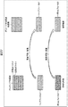
- FIG. 4 is a diagram illustrating resolution conversion performed by the resolution conversion device 21C of FIG.
- the multi-viewpoint color image (the same applies to the multi-viewpoint depth image) is, for example, a central viewpoint color image, a left viewpoint color image, and a right viewpoint color image, which are three viewpoint color images. To do.
- the central viewpoint color image, the left viewpoint color image, and the right viewpoint color image which are color images of three viewpoints, include, for example, three cameras, a position in front of the subject, a position on the left side toward the subject, and This is an image obtained by photographing the subject by being arranged at a position on the right side of the subject.
- the central viewpoint color image is an image whose viewpoint is the position in front of the subject.
- the left viewpoint color image is an image whose viewpoint is a position (left viewpoint) on the left side of the viewpoint (center viewpoint) of the central viewpoint color image
- the right viewpoint color image is a position on the right side (right viewpoint) from the center viewpoint. Is an image with a viewpoint.
- multi-view color image may be an image of two viewpoints or an image of four or more viewpoints.
- the central viewpoint color image among the central viewpoint color image, the left viewpoint color image, and the right viewpoint color image, which are multi-viewpoint color images supplied thereto is directly (resolution converted). Output).
- the resolution conversion device 21C converts the resolutions of the two viewpoint images into low resolutions for the remaining left viewpoint color image and right viewpoint color image of the multi-viewpoint color image, and converts them into an image for one viewpoint. By performing packing to be combined, a packing color image is generated and output.
- the resolution conversion device 21C halves the vertical resolution (number of pixels) of each of the left viewpoint color image and the right viewpoint color image and halves the vertical resolution (vertical resolution).
- the left viewpoint color image is arranged on the upper side
- the right viewpoint color image is arranged on the lower side.
- the central viewpoint color image and packing color image output from the resolution conversion device 21C are supplied to the encoding device 22C as a resolution conversion multi-viewpoint color image.
- the multi-viewpoint color image supplied to the resolution conversion device 21C is an image for three viewpoints of the central viewpoint color image, the left viewpoint color image, and the right viewpoint color image, and the resolution conversion device 21C outputs the images.
- the resolution-converted multi-viewpoint color image is an image for two viewpoints of the central viewpoint color image and the packing color image, and the data amount in the baseband is reduced.
- the left viewpoint color image and the right viewpoint color image among the central viewpoint color image, the left viewpoint color image, and the right viewpoint color image constituting the multi-viewpoint color image are equivalent to one viewpoint.
- the packing color image is packed, the packing can be performed on color images of two arbitrary viewpoints among the central viewpoint color image, the left viewpoint color image, and the right viewpoint color image.
- the display of the 2D image includes a central viewpoint color image, a left viewpoint color image, and a right viewpoint color image constituting the multi-viewpoint color image.
- the central viewpoint color image is expected to be used. Therefore, in FIG. 4, the central viewpoint color image is not a packing target for converting the resolution to a low resolution so that the 2D image can be displayed with high image quality.
- the receiving device 12 side all of the central viewpoint color image, the left viewpoint color image, and the right viewpoint color image constituting the multi-viewpoint color image are used for displaying the 3D image. For example, only the central viewpoint color image among the central viewpoint color image, the left viewpoint color image, and the right viewpoint color image is used. Therefore, on the receiving device 12 side, the left viewpoint color image and the right viewpoint color image among the central viewpoint color image, the left viewpoint color image, and the right viewpoint color image that constitute the multi-viewpoint color image are 3D images. In FIG. 4, the left viewpoint color image and the right viewpoint color image that are used only for displaying the 3D image are targeted for packing.
- FIG. 5 is a block diagram illustrating a configuration example of the encoding device 22C in FIG.
- the encoding device 22C in FIG. 5 encodes the central viewpoint color image, which is a resolution-converted multi-view color image from the resolution conversion device 21C (FIGS. 2 and 4), and the packing color image by MVC.
- the central viewpoint color image is a base view image, and an image of another viewpoint, that is, a packed color image is treated as a non-base view image.
- the encoding device 22C includes encoders 41 and 42 and a DPB (Decode (Picture Buffer) 43.
- DPB Decode (Picture Buffer) 43.
- the encoder 41 is supplied with the central viewpoint color image of the central viewpoint color image and the packing color image constituting the resolution conversion multi-viewpoint color image from the resolution conversion device 21C.
- the encoder 41 encodes the central viewpoint color image as an image of the base view by MVC (AVC), and outputs the encoded data of the central viewpoint color image obtained as a result.
- MVC MVC
- the encoder 42 is supplied with the packing color image of the central viewpoint color image and the packing color image constituting the resolution conversion multi-view color image from the resolution conversion device 21C.
- the encoder 42 encodes the packing color image as a non-base view image by MVC, and outputs the encoded data of the packing color image obtained as a result.
- the encoded data of the central viewpoint color image output from the encoder 41 and the encoded data of the packing color image output from the encoder 42 are sent to the multiplexing device 23 (FIG. 2) as multi-view color image encoded data. Supplied.
- the DPB 43 encodes an image to be encoded by each of the encoders 41 and 42, and a local decoded image (decoded image) obtained by local decoding is a reference image (candidate) that is referred to when a predicted image is generated. As a temporary store.
- the encoders 41 and 42 predictively encode the image to be encoded. Therefore, the encoders 41 and 42 encode the image to be encoded to generate a predicted image used for predictive encoding, and then perform local decoding to obtain a decoded image.
- the DPB 43 is a shared buffer that temporarily stores decoded images obtained by the encoders 41 and 42.
- the encoders 41 and 42 each encode an image to be encoded from the decoded images stored in the DPB 43.
- the reference image to be referred to is selected. Then, each of the encoders 41 and 42 generates a predicted image using the reference image, and performs image encoding (predictive encoding) using the predicted image.
- each of the encoders 41 and 42 can also refer to decoded images obtained by other encoders in addition to the decoded images obtained by itself.
- the encoder 41 refers to only the decoded image obtained by the encoder 41 in order to encode the base view image.
- FIG. 6 is a diagram for explaining a picture (reference image) that is referred to when a predicted image is generated in MVC predictive coding.
- the picture of the base view image is represented as p11, p12, p13,...
- the picture of the non-base view image is represented by p21, p22, p23,. Let's represent.
- the base view picture for example, the picture p12 is predictively encoded by referring to the base view picture, for example, the pictures p11 and p13 as necessary.
- prediction generation of a predicted image
- prediction can be performed with reference to only the pictures p11 and p13 that are pictures at other display times of the base view.
- a non-base view picture for example, a picture p22
- a non-base view picture for example, the pictures p21 and p23
- a base view picture p12 which is another view, as necessary.
- prediction encoding is performed.
- the non-base view picture p22 refers to the pictures p21 and p23 that are pictures at other display times of the non-base view, and the base view picture p12 that is a picture of another view, and performs prediction. Can do.
- prediction performed with reference to a picture (at another display time) of the same view as the encoding target picture is also referred to as temporal prediction, and is performed with reference to a picture of a view different from the encoding target picture.
- This prediction is also called parallax prediction.
- a picture of a view different from the encoding target picture that is referred to in the disparity prediction must be a picture having the same display time as the encoding target picture.
- FIG. 7 is a diagram for explaining the encoding (and decoding) order of pictures in MVC.
- the pictures of the base view image are represented as p11, p12, p13,...
- the pictures of the non-base view images are represented by p21, p22, p23,. It will be expressed as.
- the second picture p22 is encoded.
- the base view picture and the non-base view picture are encoded in the same order.
- FIG. 8 is a diagram illustrating temporal prediction and parallax prediction performed by the encoders 41 and 42 in FIG.
- the horizontal axis represents the time of encoding (decoding).
- temporal prediction is performed by referring to another picture of the central viewpoint color image that has already been encoded. be able to.
- temporal prediction that refers to another picture of a packed color image that has already been encoded
- Disparity prediction that refers to a picture of a central viewpoint color image (already encoded) (a picture at the same time as a picture of a packing color image to be encoded (the same POC (Picture) Order Count))
- FIG. 9 is a block diagram showing a configuration example of the encoder 42 of FIG.
- an encoder 42 includes an A / D (Analog / Digital) conversion unit 111, a screen rearrangement buffer 112, a calculation unit 113, an orthogonal transformation unit 114, a quantization unit 115, a variable length encoding unit 116, and a storage buffer 117. , An inverse quantization unit 118, an inverse orthogonal transform unit 119, a calculation unit 120, a deblocking filter 121, an intra prediction unit 122, an inter prediction unit 123, and a predicted image selection unit 124.
- a / D Analog / Digital
- the A / D converter 111 is sequentially supplied with pictures of packing color images, which are images to be encoded (moving images), in the display order.
- the A / D converter 111 When the picture supplied to the A / D converter 111 is an analog signal, the A / D converter 111 performs A / D conversion on the analog signal and supplies it to the screen rearrangement buffer 112.
- the screen rearrangement buffer 112 temporarily stores the pictures from the A / D conversion unit 111, and reads out the pictures according to a predetermined GOP (Group of Pictures) structure, thereby arranging the picture arrangement in the display order. From this, the rearrangement is performed in the order of encoding (decoding order).
- GOP Group of Pictures
- the picture read from the screen rearrangement buffer 112 is supplied to the calculation unit 113, the intra prediction unit 122, and the inter prediction unit 123.
- the calculation unit 113 is supplied with a picture from the screen rearrangement buffer 112 and a prediction image generated by the intra prediction unit 122 or the inter prediction unit 123 from the prediction image selection unit 124.
- the calculation unit 113 sets the picture read from the screen rearrangement buffer 112 as a target picture to be encoded, and sequentially sets macroblocks constituting the target picture as a target block to be encoded.
- the calculation unit 113 calculates a subtraction value obtained by subtracting the pixel value of the prediction image supplied from the prediction image selection unit 124 from the pixel value of the target block as necessary, and supplies the calculated value to the orthogonal transformation unit 114.
- the orthogonal transform unit 114 performs orthogonal transform such as discrete cosine transform and Karhunen-Loeve transform on the target block (the pixel value or the residual obtained by subtracting the predicted image) from the computation unit 113, and The transform coefficient obtained as a result is supplied to the quantization unit 115.
- the quantization unit 115 quantizes the transform coefficient supplied from the orthogonal transform unit 114, and supplies the quantized value obtained as a result to the variable length coding unit 116.
- variable length coding unit 116 performs variable length coding (for example, CAVLC (Context-Adaptive Variable Length Coding)) or arithmetic coding (for example, CABAC (Context) on the quantized value from the quantization unit 115. -Adaptive Binary Arithmetic Coding), etc.) and the like, and the encoded data obtained as a result is supplied to the accumulation buffer 117.
- variable length coding for example, CAVLC (Context-Adaptive Variable Length Coding)
- CABAC Context
- CABAC Context
- CABAC Context-Adaptive Binary Arithmetic Coding
- variable length encoding unit 116 is supplied with the quantization value from the quantization unit 115 and the header information included in the header of the encoded data from the prediction image selection unit 124.
- variable length encoding unit 116 encodes the header information from the predicted image selection unit 124 and includes it in the header of the encoded data.
- the accumulation buffer 117 temporarily stores the encoded data from the variable length encoding unit 116 and outputs (transmits) it at a predetermined data rate.
- the quantization value obtained by the quantization unit 115 is supplied to the variable length coding unit 116 and also to the inverse quantization unit 118, and the inverse quantization unit 118, the inverse orthogonal transform unit 119, and the calculation In unit 120, local decoding is performed.
- the inverse quantization unit 118 inversely quantizes the quantized value from the quantization unit 115 into a transform coefficient and supplies the transform coefficient to the inverse orthogonal transform unit 119.
- the inverse orthogonal transform unit 119 performs inverse orthogonal transform on the transform coefficient from the inverse quantization unit 118 and supplies it to the arithmetic unit 120.
- the calculation unit 120 decodes the target block by adding the pixel value of the predicted image supplied from the predicted image selection unit 124 to the data supplied from the inverse orthogonal transform unit 119 as necessary. A decoded image is obtained and supplied to the deblocking filter 121.
- the deblocking filter 121 removes (reduces) block distortion generated in the decoded image by filtering the decoded image from the arithmetic unit 120, and supplies it to the DPB 43 (FIG. 5).
- the DPB 43 predictively encodes the decoded image from the deblocking filter 121, that is, the picture of the packed color image encoded by the encoder 42 and locally decoded (predicted by the calculation unit 113). This is stored as a reference image (candidate) to be referred to when generating a predicted image used for (encoding where image subtraction is performed).
- the DPB 43 is shared by the encoders 41 and 42, in addition to the picture of the packed color image encoded and locally decoded by the encoder 42, it is encoded and locally decoded by the encoder 41. A picture of the central viewpoint color image is also stored.
- local decoding by the inverse quantization unit 118, the inverse orthogonal transform unit 119, and the calculation unit 120 is, for example, an I picture, a P picture, and a reference picture that can be a reference image (reference picture).
- the DPB 43 decoded pictures of I picture, P picture, and Bs picture are stored.
- the target picture is an I picture, a P picture, or a B picture (including a Bs picture) that can be subjected to intra prediction (intra-screen prediction)
- intra prediction intra-screen prediction
- a portion (decoded image) that has already been locally decoded is read.
- the intra-screen prediction unit 122 sets a part of the decoded image of the target picture read from the DPB 43 as the predicted image of the target block of the target picture supplied from the screen rearrangement buffer 112.
- the intra-screen prediction unit 122 calculates the encoding cost required to encode the target block using the predicted image, that is, the encoding cost required to encode the residual of the target block with respect to the predicted image. Obtained and supplied to the predicted image selection unit 124 together with the predicted image.
- the inter prediction unit 123 encodes a picture that has been encoded and locally decoded from the DPB 43 before the target picture. And read out as a reference image.
- the inter prediction unit 123 performs a corresponding block corresponding to the target block of the target block and the reference image by ME (Motion ⁇ Estimation) using the target block of the target picture from the screen rearrangement buffer 112 and the reference image.
- ME Motion ⁇ Estimation
- a deviation vector representing a deviation (parallax, motion) from a target block for example, a block that minimizes SAD (Sum Absolute Differences) or the like) with the target block is detected.
- the reference image is a picture of the same view as the target picture (at a different time from the target picture)
- the shift vector detected by the ME using the target block and the reference image is the target block
- the reference This is a motion vector representing a motion (temporal shift) between the images.
- the shift vector detected by the ME using the target block and the reference image is the target block, the reference image, It becomes a parallax vector representing the parallax (spatial shift) between the two.
- the inter prediction unit 123 performs shift compensation (motion compensation that compensates for a shift for motion, or parallax compensation that compensates for a shift for parallax, which is MC (Motion Compensation) of the reference image from the DPB 43 in accordance with the shift vector of the target block. ) To generate a predicted image.
- shift compensation motion compensation that compensates for a shift for motion, or parallax compensation that compensates for a shift for parallax, which is MC (Motion Compensation) of the reference image from the DPB 43 in accordance with the shift vector of the target block.
- the inter prediction unit 123 acquires, as a predicted image, a corresponding block that is a block (region) at a position shifted (shifted) from the position of the target block in the reference image according to the shift vector of the target block.
- the inter prediction unit 123 obtains an encoding cost required for encoding the target block using a prediction image for each inter prediction mode having different macroblock types and the like to be described later.
- the inter prediction unit 123 sets the inter prediction mode with the minimum encoding cost as the optimal inter prediction mode that is the optimal inter prediction mode, and the prediction image and the encoding cost obtained in the optimal inter prediction mode.
- the predicted image selection unit 124 is supplied.
- deviation prediction generating a predicted image based on a deviation vector (disparity vector, motion vector)
- deviation compensation deviation compensation, motion compensation
- the predicted image selection unit 124 selects a predicted image with a low encoding cost from the predicted images from the intra-screen prediction unit 122 and the inter prediction unit 123, and supplies them to the calculation units 113 and 120.
- the intra-screen prediction unit 122 supplies information related to intra prediction (prediction mode-related information) to the predicted image selection unit 124, and the inter prediction unit 123 uses information related to inter prediction (information about shift vectors and reference images). Prediction mode related information including the assigned reference index) is supplied to the predicted image selection unit 124.
- the predicted image selection unit 124 selects information from the one in which the predicted image with the lower encoding cost is generated among the information from the intra-screen prediction unit 122 and the inter prediction unit 123, and as header information, This is supplied to the variable length coding unit 116.
- the encoder 41 in FIG. 5 is also configured similarly to the encoder 42 in FIG. However, in the encoder 41 that encodes the image of the base view, disparity prediction is not performed in inter prediction, and only temporal prediction is performed.
- FIG. 10 is a diagram for explaining a macroblock type of MVC (AVC).
- a macroblock that is a target block is a block of 16 ⁇ 16 pixels in horizontal ⁇ vertical, but ME (and prediction image generation) is performed for each partition by dividing the macroblock into partitions. Can do.
- a macroblock is divided into any partition of 16 ⁇ 16 pixels, 16 ⁇ 8 pixels, 8 ⁇ 16 pixels, or 8 ⁇ 8 pixels, and ME is performed for each partition.
- a shift vector motion vector or disparity vector
- an 8 ⁇ 8 pixel partition is further divided into any one of 8 ⁇ 8 pixels, 8 ⁇ 4 pixels, 4 ⁇ 8 pixels, or 4 ⁇ 4 pixels, and each subpartition
- ME can be performed to detect a shift vector (motion vector or disparity vector).
- the macro block type represents what partition (and sub-partition) the macro block is divided into.
- the encoding cost of each macroblock type is calculated as the encoding cost of each inter prediction mode, and the inter prediction mode (macroblock type) with the minimum encoding cost is calculated. ) Is selected as the optimal inter prediction mode.
- FIG. 11 is a diagram for explaining a prediction vector (PMV) of MVC (AVC).
- a shift vector motion vector or disparity vector
- a predicted image is generated using the shift vector.
- the shift vector Since the shift vector is necessary for decoding the image on the decoding side, it is necessary to encode the shift vector information and include it in the encoded data. However, if the shift vector is encoded as it is, The amount of code increases and the coding efficiency may deteriorate.
- the macroblock is divided into 8 ⁇ 8 pixel partitions, and each of the 8 ⁇ 8 pixel partitions is further divided into 4 ⁇ 4 pixel sub-partitions.
- a prediction vector generated by MVC differs depending on a reference index (hereinafter also referred to as a prediction reference index) assigned to a reference image used for generating a prediction image of a macroblock around the target block.
- a reference index hereinafter also referred to as a prediction reference index assigned to a reference image used for generating a prediction image of a macroblock around the target block.
- AVC when generating a predicted image, a plurality of pictures can be used as reference images.
- the reference image is stored in a buffer called DPB after decoding (local decoding).
- the DPB is managed by the FIFO (First In First Out) method, and the pictures stored in the DPB are released in order from the picture with the smallest frame_num (becomes non-reference images).
- FIFO First In First Out
- the I (Intra) picture, the P (Predictive) picture, and the Bs picture that is a reference B (Bi-directional Predictive) picture are stored in the DPB as a short-time reference picture.
- the moving window memory management method does not affect the long-term reference image stored in the DPB. That is, in the moving window memory management method, only the short-time reference image is managed by the FIFO method among the reference images.
- pictures stored in the DPB are managed using a command called MMCO (Memory management control operation).
- MMCO Memory management control operation
- a short-time reference image as a non-reference image for a reference image stored in the DPB, or a reference index for managing a long-time reference image for a short-time reference image.
- a long-term frame index setting a short-time reference image as a long-time reference image, setting a maximum value of long-term frame index, setting all reference images as non-reference images Etc. can be performed.
- inter prediction for generating a predicted image is performed by performing motion compensation (displacement compensation) on a reference image stored in the DPB, but for inter prediction of B pictures (including Bs pictures)
- Two-picture reference images can be used.
- the inter prediction using the reference picture of the two pictures is called L0 (List 0) prediction and L1 (List 1) prediction, respectively.
- L0 prediction, L1 prediction, or both L0 prediction and L1 prediction are used as inter prediction.
- L0 prediction is used as inter prediction.
- reference images that are referred to for generating predicted images are managed by a reference list (Reference Picture List).
- a reference index that is an index for designating a reference image (possible reference image) to be referred to in generating a predicted image is assigned to a reference image (possible picture) stored in the DPB. It is done.
- the reference index is assigned only for the L0 prediction.
- both the L0 prediction and the L1 prediction may be used as the inter prediction for the B picture. Is assigned to both the L0 prediction and the L1 prediction.
- the reference index for L0 prediction is also referred to as L0 index
- the reference index for L1 prediction is also referred to as L1 index.
- a reference index (L0 index) having a smaller value is assigned to the reference picture stored in the DPB as the reference picture is later in decoding order.
- the reference index is an integer value of 0 or more, and the minimum value is 0. Therefore, when the target picture is a P picture, 0 is assigned as the L0 index to the reference picture decoded immediately before the target picture.
- the reference index (L0 index, L0 index, POC (Picture Order Count) order is the default for AVC. And L1 index).
- an L0 index having a smaller value is assigned to a reference image closer to the target picture with respect to a reference image temporally previous to the target picture in display order, and then the target picture is displayed in display order.
- an L0 index having a smaller value is assigned to a reference image that is closer to the target picture.
- a reference image closer to the target picture is assigned a lower L1 index to a reference image that is temporally later than the target picture in display order, and then the target picture is displayed in display order.
- An L1 index having a smaller value is assigned to a reference image that is closer to the target picture with respect to a temporally previous reference image.
- the reference index (L0 index and L1 index) by default of the above AVC is assigned to a short-time reference image.
- the assignment of the reference index to the long-time reference image is performed after the reference index is assigned to the short-time reference image.
- a reference index having a larger value than that of the short-time reference image is assigned to the long-time reference image.
- any allocation can be performed by using a command called Reference Picture List Reordering (hereinafter also referred to as RPLR command). .
- RPLR command Reference Picture List Reordering
- the reference index is assigned to the reference image by a default method.
- the prediction vector PMVX of the shift vector mvX of the target block X is, as shown in FIG. 11, the macroblock A adjacent to the left of the target block X, the macroblock B adjacent above, and the diagonally right It is obtained in a different manner depending on the reference index for prediction of each of the adjacent macroblocks C (reference indexes assigned to the reference images used for generating the prediction images of the macroblocks A, B, and C). .
- the reference index ref_idx for prediction of the target block X is 0, for example.
- the shift vector of the one macroblock (the macroblock for which the prediction reference index ref_idx is 0) is set as the prediction vector PMVX of the shift vector mvX of the target block X.
- the macroblock B among the three macroblocks A to C adjacent to the target block X is a macroblock whose reference index ref_idx for prediction is 0.
- the shift vector mvB of the macroblock A is set as the prediction vector PMVX of the target block X (shift vector mvX).
- the median of the shift vector of two or more macroblocks for which the reference index ref_idx for prediction is 0 is set as the prediction vector PMVX of the target block X.
- the 0 vector is set as the prediction vector PMVX of the target block X.
- the target block X when the reference index ref_idx for prediction of the target block X is 0, the target block X can be encoded as a skip macroblock (skip mode).
- the prediction vector is used as it is as the shift vector of the skip macroblock, and a copy of the block (corresponding block) at the position shifted by the shift vector (prediction vector) from the position of the skip macroblock in the reference image , The decoding result of the skip macroblock.
- the target block is a skip macroblock depends on the specifications of the encoder, but is determined (determined) based on, for example, the amount of encoded data, the encoding cost of the target block, and the like.
- FIG. 12 is a block diagram illustrating a configuration example of the inter prediction unit 123 of the encoder 42 of FIG.
- the inter prediction unit 123 includes a parallax prediction unit 131 and a time prediction unit 132.
- the DPB 43 is supplied from the deblocking filter 121 with a decoded image, that is, a picture of a packing color image (hereinafter also referred to as a decoding packing color image) encoded by the encoder 42 and locally decoded. And stored as a reference image (possible picture).
- a decoded image that is, a picture of a packing color image (hereinafter also referred to as a decoding packing color image) encoded by the encoder 42 and locally decoded. And stored as a reference image (possible picture).
- the DPB 43 is also supplied with and stored a picture of a central viewpoint color image (hereinafter also referred to as a decoded central viewpoint color image) encoded by the encoder 41 and locally decoded. Is done.
- a central viewpoint color image hereinafter also referred to as a decoded central viewpoint color image
- the picture of the decoded central viewpoint color image obtained by the encoder 41 is the predicted image for encoding the packing color image to be encoded (for Used to generate). For this reason, in FIG. 12, an arrow indicating that the decoded central viewpoint color image obtained by the encoder 41 is supplied to the DPB 43 is illustrated. *
- the target picture of the packing color image is supplied from the screen rearrangement buffer 112 to the parallax prediction unit 131.
- the disparity prediction unit 131 refers to the picture of the decoded central viewpoint color image (picture at the same time as the target picture) stored in the DPB 43 for the disparity prediction of the target block of the target picture of the packed color image from the screen rearrangement buffer 112 This is used as an image to generate a predicted image of the target block.
- the disparity prediction unit 131 obtains the disparity vector of the target block by performing ME using the decoded central viewpoint color image stored in the DPB 43 as a reference image.
- the disparity prediction unit 131 generates a predicted image of the target block by performing MC using the picture of the decoded central viewpoint color image stored in the DPB 43 as a reference image according to the disparity vector of the target block.
- the disparity prediction unit 131 calculates, for each macroblock type, an encoding cost required for encoding the target block (predictive encoding) using a predicted image obtained from the reference image by disparity prediction.
- the disparity prediction unit 131 selects a macroblock type with the lowest coding cost as the optimal inter prediction mode, and uses the predicted image (disparity prediction image) generated in the optimal inter prediction mode as the predicted image selection unit 124. To supply.
- parallax prediction unit 131 supplies information such as the optimal inter prediction mode to the predicted image selection unit 124 as header information.
- a reference index is assigned to the reference image, and the reference image is assigned to the reference image that is referred to when the predicted image generated in the optimal inter prediction mode is generated in the parallax prediction unit 131.
- the reference index is selected as a reference index for prediction of the target block, and is supplied to the predicted image selection unit 124 as one piece of header information.
- the time prediction unit 132 is supplied with the target picture of the packing color image from the screen rearrangement buffer 112.
- the temporal prediction unit 132 performs temporal prediction of the target block of the target picture of the packing color image from the screen rearrangement buffer 112, and uses the decoded packing color picture stored in the DPB 43 (a picture at a time different from the target picture) as a reference image. To generate a predicted image of the target block.
- the time prediction unit 132 obtains the motion vector of the target block by performing ME using the picture of the decoded packing color image stored in the DPB 43 as a reference image.
- the temporal prediction unit 132 generates a predicted image of the target block by performing MC using the picture of the decoded packing color image stored in the DPB 43 as a reference image according to the motion vector of the target block.
- the temporal prediction unit 132 calculates an encoding cost required for encoding the target block (predictive encoding) using a prediction image obtained by temporal prediction from the reference image for each macroblock type.
- the temporal prediction unit 132 selects the macroblock type with the lowest coding cost as the optimal inter prediction mode, and uses the predicted image (temporal prediction image) generated in the optimal inter prediction mode as the predicted image selection unit 124. To supply.
- time prediction unit 132 supplies information such as the optimal inter prediction mode to the predicted image selection unit 124 as header information.
- a reference index is assigned to the reference image, and the reference image is assigned to the reference image that is referred to when the prediction image generated in the optimal inter prediction mode is generated in the temporal prediction unit 132.
- the reference index is selected as a reference index for prediction of the target block, and is supplied to the predicted image selection unit 124 as one piece of header information.
- the encoding cost is minimum.
- a predicted image is selected and supplied to the calculation units 113 and 120.
- a reference index having a value of 1 is assigned to a reference image referred to in disparity prediction (here, a picture of a decoded central viewpoint color image) and is referred to in temporal prediction. It is assumed that a reference index having a value of 0 is assigned to a reference image (here, a picture of a decoded packing color image).
- FIG. 13 is a block diagram illustrating a configuration example of the disparity prediction unit 131 in FIG.
- the parallax prediction unit 131 includes a parallax detection unit 141, a parallax compensation unit 142, a prediction information buffer 143, a cost function calculation unit 144, and a mode selection unit 145.
- a picture of the decoded central viewpoint color image as a reference image is supplied from the DPB 43 to the parallax detection unit 141, and a picture of the packing color image to be encoded (target picture) is supplied from the screen rearrangement buffer 112.
- the parallax detection unit 141 performs ME using the target block and the picture of the decoded central viewpoint color image that is the reference image, so that, for example, in the picture of the target block and the decoded central viewpoint color image, A disparity vector mv representing a deviation from the corresponding block that provides the best coding efficiency such as minimizing SAD or the like is detected for each macroblock type and supplied to the disparity compensation unit 142.
- the parallax compensation unit 142 is supplied with a parallax vector mv from the parallax detection unit 141, and is also supplied with a picture of a decoded central viewpoint color image as a reference image from the DPB 43.
- the parallax compensation unit 142 generates a predicted image of the target block for each macroblock type by performing parallax compensation of the reference image from the DPB 43 using the parallax vector mv of the target block from the parallax detection unit 141.
- the disparity compensation unit 142 acquires, as a predicted image, a corresponding block that is a block (region) at a position shifted by the disparity vector mv from the position of the target block in the picture of the decoded central viewpoint color image as a reference image. .
- the parallax compensation unit 142 obtains the prediction vector PMV of the parallax vector mv of the target block using the parallax vectors of the macroblocks around the target block that have already been encoded as necessary.
- the disparity compensation unit 142 obtains a residual vector that is a difference between the disparity vector mv of the target block and the prediction vector PMV.
- the parallax compensation unit 142 uses the prediction image of the target block for each prediction mode such as the macroblock type, the residual vector of the target block, and the reference image (in this case, the decoding image) used to generate the prediction image.
- the reference index assigned to the picture of the central viewpoint color image) is associated with the prediction mode and supplied to the prediction information buffer 143 and the cost function calculation unit 144.
- the prediction information buffer 143 temporarily stores the prediction image, the residual vector, and the reference index associated with the prediction mode from the parallax compensation unit 142 as prediction information together with the prediction mode.
- the cost function calculation unit 144 is supplied with the prediction image, the residual vector, and the reference index associated with the prediction mode from the parallax compensation unit 142, and from the screen rearrangement unit buffer 112 with the packing color image.
- the target picture is supplied.
- the cost function calculating unit 144 calculates a coding cost for a coding cost required for coding the target block of the target picture from the screen rearrangement buffer 112 for each macroblock type (FIG. 10) as the prediction mode. It is obtained according to the cost function.
- the cost function calculation unit 144 obtains a value MV corresponding to the code amount of the residual vector from the parallax compensation unit 142 and corresponds to the code amount of the reference index (prediction reference index) from the parallax compensation unit 142. Find the value IN.
- the cost function calculation unit 144 obtains a SAD that is a value D corresponding to the residual code amount of the target block for the prediction image from the parallax compensation unit 142.
- the cost function calculation unit 144 When the cost function calculation unit 144 obtains the coding cost (cost function value) for each macroblock type, the cost function calculation unit 144 supplies the coding cost to the mode selection unit 145.
- the mode selection unit 145 detects the minimum cost, which is the minimum value, from the encoding costs for each macroblock type from the cost function calculation unit 144.
- the mode selection unit 145 selects the macro block type for which the minimum cost is obtained as the optimum inter prediction mode.
- the mode selection part 145 reads the prediction image matched with the prediction mode which is the optimal inter prediction mode, a residual vector, and a reference index from the prediction information buffer 143, and with the prediction mode which is the optimal inter prediction mode. And supplied to the predicted image selection unit 124.
- the prediction mode (optimum inter prediction mode), the residual vector, and the reference index (prediction reference index) supplied from the mode selection unit 145 to the prediction image selection unit 124 are inter-prediction (here, disparity).
- Prediction mode related information related to (prediction) and the prediction image selection unit 124 supplies the prediction mode related information related to this inter prediction to the variable length encoding unit 116 (FIG. 9) as header information as necessary. .
- the temporal prediction unit 132 in FIG. 12 performs the same processing as the parallax prediction unit 131 in FIG. 13 except that the reference image is not a decoded central viewpoint color image but a decoded packing color image. Is called.
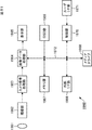
- FIG. 14 is a block diagram illustrating a configuration example of the decoding device 32C in FIG.
- the decoding device 32C includes decoders 211 and 212, and a DPB 213.
- the decoder 211 is supplied with the encoded data of the central viewpoint color image that is the base view image.
- the decoder 211 decodes the encoded data of the central viewpoint color image supplied thereto by MVC, and outputs the central viewpoint color image obtained as a result.
- the decoder 212 is supplied with encoded data of a packed color image that is a non-base view image.
- the decoder 212 decodes the encoded data of the packing color image supplied thereto by MVC, and outputs the resulting packing color image.
- the central viewpoint color image output from the decoder 211 and the packing color image output from the decoder 212 are supplied to the resolution reverse conversion device 33C (FIG. 3) as a resolution conversion multi-viewpoint color image.
- the DPB 213 temporarily stores the decoded image (decoded image) obtained by decoding the decoding target image in each of the decoders 211 and 212 as a reference image (candidate) to be referred to when the predicted image is generated.
- the decoders 211 and 212 decode the images that have been predictively encoded by the encoders 41 and 42 in FIG.
- the decoders 211 and 212 perform decoding in order to generate a predictive image used in predictive encoding. After decoding the target image, the decoded image used for generating the predicted image is temporarily stored in the DPB 213.
- the DPB 213 is a shared buffer for temporarily storing the decoded images (decoded images) obtained by the decoders 211 and 212, respectively.
- the decoders 211 and 212 each receive an image to be decoded from the decoded images stored in the DPB 213.
- a reference image to be referenced for decoding is selected, and a predicted image is generated using the reference image.
- each of the decoders 211 and 212 can refer to a decoded image obtained by itself as well as a decoded image obtained by another decoder.
- the decoder 211 decodes the image of the base view, only the decoded image obtained by the decoder 211 is referred to (no parallax prediction is performed).
- FIG. 15 is a block diagram showing a configuration example of the decoder 212 in FIG.
- a decoder 212 includes an accumulation buffer 241, a variable length decoding unit 242, an inverse quantization unit 243, an inverse orthogonal transform unit 244, a calculation unit 245, a deblocking filter 246, a screen rearrangement buffer 247, and a D / A conversion unit. 248, an intra prediction unit 249, an inter prediction unit 250, and a predicted image selection unit 251.
- the storage buffer 241 is supplied with the encoded data of the packed color image from the encoded data of the central viewpoint color image and the packed color image constituting the multi-view color image encoded data from the demultiplexer 31. Is done.
- the accumulation buffer 241 temporarily stores the encoded data supplied thereto and supplies the encoded data to the variable length decoding unit 242.
- variable length decoding unit 242 performs variable length decoding on the encoded data from the accumulation buffer 241 to restore the prediction mode related information that is a quantized value or header information. Then, the variable length decoding unit 242 supplies the quantization value to the inverse quantization unit 243 and supplies the header information (prediction mode related information) to the in-screen prediction unit 249 and the inter prediction unit 250.
- the inverse quantization unit 243 inversely quantizes the quantized value from the variable length decoding unit 242 into a transform coefficient and supplies the transform coefficient to the inverse orthogonal transform unit 244.
- the inverse orthogonal transform unit 244 performs inverse orthogonal transform on the transform coefficient from the inverse quantization unit 243 and supplies the transform coefficient to the arithmetic unit 245 in units of macroblocks.
- the calculation unit 245 sets the macroblock supplied from the inverse orthogonal transform unit 244 as a target block to be decoded, and adds the predicted image supplied from the predicted image selection unit 251 to the target block as necessary. Thus, a decoded image is obtained and supplied to the deblocking filter 246.
- the deblocking filter 246 performs, for example, the same filtering as the deblocking filter 121 of FIG. 9 on the decoded image from the arithmetic unit 245, and supplies the decoded image after filtering to the screen rearrangement buffer 247.
- the screen rearrangement buffer 247 temporarily stores and reads out the picture of the decoded image from the deblocking filter 246, thereby rearranging the picture arrangement to the original arrangement (display order), and D / A (Digital / Analog) This is supplied to the conversion unit 248.
- the D / A conversion unit 248 When the D / A conversion unit 248 needs to output the picture from the screen rearrangement buffer 247 as an analog signal, the D / A conversion unit 248 performs D / A conversion on the picture and outputs it.
- the deblocking filter 246 supplies the decoded images of the I picture, the P picture, and the Bs picture, which are referenceable pictures among the decoded images after filtering, to the DPB 213.
- the DPB 213 stores the picture of the decoded image from the deblocking filter 246, that is, the picture of the packing color image, as a reference image to be referred to when generating a prediction image used for decoding performed later in time.
- the DPB 213 is shared by the decoders 211 and 212, so that the central viewpoint color decoded by the decoder 211 as well as the picture of the packing color image (decoded packing color image) decoded by the decoder 212.
- the picture of the image (decoded central viewpoint color image) is also stored.
- the intra prediction unit 249 recognizes whether or not the target block is encoded using a prediction image generated by intra prediction (intra prediction) based on the header information from the variable length decoding unit 242.
- the intra-screen prediction unit 249 receives a picture including the target block from the DPB 213, as in the intra-screen prediction unit 122 of FIG. A portion (decoded image) that has already been decoded in the target picture) is read out. Then, the in-screen prediction unit 249 supplies a part of the decoded image of the target picture read from the DPB 213 to the predicted image selection unit 251 as the predicted image of the target block.
- the inter prediction unit 250 recognizes based on the header information from the variable length decoding unit 242 whether the target block is encoded using a prediction image generated by inter prediction.
- the inter prediction unit 250 When the target block is encoded using a prediction image generated by inter prediction, the inter prediction unit 250 performs prediction reference based on header information (prediction mode related information) from the variable length decoding unit 242.
- the index that is, the reference index assigned to the reference image used to generate the predicted image of the target block is recognized.
- the inter prediction unit 250 reads, as a reference image, a picture to which a reference index for prediction is assigned from the picture of the decoded packing color image and the picture of the decoded central viewpoint color image stored in the DPB 213.
- the inter prediction unit 250 recognizes a shift vector (disparity vector, motion vector) used to generate a predicted image of the target block based on the header information from the variable length decoding unit 242, and the inter prediction unit in FIG. In the same manner as in 123, a predicted image is generated by performing compensation for a reference image (motion compensation that compensates for a displacement for motion or parallax compensation that compensates for a displacement for disparity) according to the displacement vector.
- a shift vector displacement vector, motion vector
- the inter prediction unit 250 acquires, as a predicted image, a block (corresponding block) at a position moved (shifted) from the position of the target block of the reference image according to the shift vector of the target block.
- the inter prediction unit 250 supplies the predicted image to the predicted image selection unit 251.
- the prediction image selection unit 251 selects the prediction image when the prediction image is supplied from the intra-screen prediction unit 249, and selects the prediction image when the prediction image is supplied from the inter prediction unit 250. And supplied to the calculation unit 245.
- FIG. 16 is a block diagram illustrating a configuration example of the inter prediction unit 250 of the decoder 212 in FIG.
- the inter prediction unit 250 includes a reference index processing unit 260, a parallax prediction unit 261, and a time prediction unit 262.
- the DPB 213 is supplied from the deblocking filter 246 with the decoded image, that is, the picture of the decoded packed color image decoded by the decoder 212, and stored as a reference image.
- the DPB 213 is also supplied with the picture of the decoded central viewpoint color image decoded by the decoder 211 and stored therein. For this reason, in FIG. 16, an arrow indicating that the decoded central viewpoint color image obtained by the decoder 211 is supplied to the DPB 213 is illustrated.
- the reference index processing unit 260 is supplied with the reference index (for prediction) of the target block in the prediction mode related information which is the header information from the variable length decoding unit 242.
- the reference index processing unit 260 reads, from the DPB 213, the picture of the decoded central viewpoint color image or the picture of the decoded packed color image to which the reference index for prediction of the target block from the variable length decoding unit 242 is assigned, and the disparity The data is supplied to the prediction unit 261 or the time prediction unit 262.
- a reference index having a value of 1 is assigned to the picture of the decoded central viewpoint color image, which is a reference image referred to in the parallax prediction, in the encoder 42.
- a reference index having a value of 0 is assigned to a picture of a decoded packing color image that is a reference image that is referred to in temporal prediction.
- the reference index for predicting the target block can recognize the picture of the decoded central viewpoint color image or the picture of the decoded packing color image, which is the reference image used to generate the predicted image of the target block. Furthermore, it can be recognized whether the deviation prediction performed when generating the prediction image of the target block is one of temporal prediction and parallax prediction.
- the reference index processing unit 260 when the picture to which the reference index for prediction of the target block from the variable length decoding unit 242 is assigned is a picture of the decoded central viewpoint color image (the reference index for prediction is 1). In this case, since the predicted image of the target block is generated by parallax prediction, the picture of the decoded central viewpoint color image to which the reference index for prediction (reference index that matches) is assigned is read from the DPB 213 as a reference image. And supplied to the parallax prediction unit 261.
- the reference index processing unit 260 when the picture to which the reference index for prediction of the target block from the variable length decoding unit 242 is assigned is a picture of a decoded packing color image (the prediction reference index is 0). In some cases, since the predicted image of the target block is generated by temporal prediction, the picture of the decoded packing color image to which the reference index for prediction (reference index that matches) is assigned is read from the DPB 213 as a reference image. To the time prediction unit 262.
- the prediction mode related information which is header information from the variable length decoding unit 242, is supplied to the parallax prediction unit 261.
- the parallax prediction unit 261 recognizes whether or not the target block is encoded using the prediction image generated by the parallax prediction based on the header information from the variable length decoding unit 242.
- the parallax prediction unit 261 is used to generate a prediction image of the target block based on the header information from the variable length decoding unit 242.
- the disparity vector is restored, and the prediction image is generated by performing disparity prediction (disparity compensation) according to the disparity vector, similarly to the disparity prediction unit 131 of FIG.
- the disparity prediction unit 261 receives the decoding central viewpoint as the reference image from the reference index processing unit 260. A picture of a color image is supplied.
- the disparity prediction unit 261 moves (shifts) a block (corresponding) from the position of the target block of the picture of the decoded central viewpoint color image as the reference image from the reference index processing unit 260 according to the disparity vector of the target block. Block) is acquired as a predicted image.
- the parallax prediction unit 261 supplies the predicted image to the predicted image selection unit 251.
- the prediction mode related information which is header information from the variable length decoding unit 242, is supplied to the time prediction unit 262.
- the time prediction unit 262 recognizes whether or not the target block is encoded using the prediction image generated by the time prediction based on the header information from the variable length decoding unit 242.
- the temporal prediction unit 262 When the target block is encoded using a prediction image generated by temporal prediction, the temporal prediction unit 262 is used to generate a prediction image of the target block based on the header information from the variable length decoding unit 242. The motion vector is restored, and the prediction image is generated by performing temporal prediction (motion compensation) according to the motion vector, similarly to the temporal prediction unit 132 of FIG.
- the temporal prediction unit 262 receives the decoding packing color as the reference image from the reference index processing unit 260 as described above. A picture of the image is supplied.
- the time prediction unit 262 moves (shifts) the block (corresponding block) from the position of the target block of the picture of the decoded packed color image as the reference image from the reference index processing unit 260 according to the motion vector of the target block. ) As a predicted image.
- the time prediction unit 262 supplies the predicted image to the predicted image selection unit 251.
- FIG. 17 is a block diagram illustrating a configuration example of the disparity prediction unit 261 in FIG.
- the parallax prediction unit 261 includes a parallax compensation unit 272.
- the parallax compensation unit 272 is supplied with a decoded central viewpoint color image as a reference image from the reference index processing unit 260, and from the variable length decoding unit 242 with a prediction mode included in mode-related information as header information, and The residual vector is supplied.
- the disparity compensation unit 272 obtains a prediction vector of the disparity vector of the target block using the disparity vector of the already decoded macroblock as necessary, and the prediction vector and the remaining of the target block from the variable length decoding unit 242 are obtained.
- the disparity vector mv of the target block is restored by adding the difference vector.
- the parallax compensation unit 272 performs parallax compensation on the picture of the decoded central viewpoint color image as the reference image from the reference index processing unit 260 by using the parallax vector mv of the target block, so that the variable length decoding unit 242 A prediction image of the target block is generated for the macroblock type represented by the prediction mode.
- the parallax compensation unit 272 acquires a corresponding block that is a block at a position shifted by the parallax vector mv from the position of the target block in the picture of the decoded central viewpoint color image as a predicted image.
- the parallax compensation unit 272 supplies the predicted image to the predicted image selection unit 251.
- temporal prediction unit 262 in FIG. 16 performs the same processing as the disparity prediction unit 261 in FIG. 17 except that the reference image is not a decoded central viewpoint color image but a decoded packed color image. Is called.
- the parallax prediction is performed. Prediction accuracy (prediction efficiency) may decrease.
- the horizontal / vertical resolution ratio of the central viewpoint color image, the left viewpoint color image, and the right viewpoint color image ratio between the number of horizontal pixels and the number of vertical pixels.
- the packing color image is a left viewpoint color image in which the vertical resolution of each of the left viewpoint color image and the right viewpoint color image is halved and the vertical resolution is halved.
- the encoder 42 (FIG. 9) refers to the resolution ratio of the packing color image (encoding target image) to be encoded and the prediction of the packing color image in the parallax prediction.
- the resolution ratio of the central viewpoint color image (decoded central viewpoint color image), which is a reference image of a viewpoint different from the packing color image, does not match (match).
- the vertical resolution (vertical resolution) of each of the left viewpoint color image and the right viewpoint color image is 1 ⁇ 2 of the original, and therefore the left color in the packing color image.
- the resolution ratio between the viewpoint color image and the right viewpoint color image is 2: 1.
- the resolution ratio of the central viewpoint color image as the reference image is 1: 1
- the resolution ratio of the left viewpoint color image and the right viewpoint color image that are the packing color image is 2: 1. Does not match.
- the prediction accuracy of the parallax prediction decreases (the residual between the predicted image generated by the parallax prediction and the target block) Encoding efficiency), and encoding efficiency deteriorates.
- FIG. 18 is a block diagram showing another configuration example of the transmission apparatus 11 of FIG.
- the transmission apparatus 11 includes resolution conversion apparatuses 321C and 321D, encoding apparatuses 322C and 322D, and a multiplexing apparatus 23.
- the transmission apparatus 11 of FIG. 18 has the multiplexing apparatus 23 in common with the case of FIG. 2, and instead of the resolution conversion apparatuses 21C and 21D and the encoding apparatuses 22C and 22D, respectively, the resolution conversion apparatus It is different from the case of FIG. 2 in that 321C and 321D and encoding devices 322C and 322D are provided.
- a multi-viewpoint color image is supplied to the resolution conversion device 321C.
- the resolution conversion device 321C performs, for example, the same processing as the resolution conversion device 21C in FIG.
- the resolution conversion device 321C performs resolution conversion for converting the multi-view color image supplied thereto into a low-resolution resolution conversion multi-view color image lower than the original resolution, and the resulting resolution conversion multi-view color image. Is supplied to the encoding device 322C.
- the resolution conversion device 321C generates resolution conversion information and supplies it to the encoding device 322C.
- the resolution conversion information generated by the resolution conversion device 321C is information relating to resolution conversion of a multi-view color image to a resolution-converted multi-view color image, which is performed by the resolution conversion device 321C.
- Resolution information regarding the resolution of the central viewpoint color image which is a reference image having a different viewpoint from the encoding target image.
- the encoding device 322C encodes the resolution-converted multi-view color image obtained as a result of the resolution conversion by the resolution converting device 321C.
- the resolution-converted multi-view color image that is the target of the encoding is shown in FIG. As described above, the central viewpoint color image and the packing color image.
- the encoding target image to be encoded using the parallax prediction is a packing color image that is a non-base view image, and is referenced in the parallax prediction of the packing color image.
- the reference image is a central viewpoint color image.
- the resolution conversion information generated by the resolution conversion device 321C includes information regarding the resolution of the packing color image and the central viewpoint color image.
- the encoding device 322C encodes the resolution-converted multi-viewpoint color image supplied from the resolution conversion device 321C by an extended method that is an extension of a standard such as MVC, which is a standard for transmitting images of a plurality of viewpoints.
- Multi-view color image encoded data which is encoded data obtained as a result, is supplied to the multiplexing device 23.
- images of a plurality of viewpoints can be transmitted, for example, a standard such as HEVC (High Efficiency Video Video Coding) Can be adopted.
- HEVC High Efficiency Video Video Coding
- a multi-view depth image is supplied to the resolution conversion device 321D.
- the resolution conversion device 321C In the resolution conversion device 321D and the encoding device 322D, the resolution conversion device 321C, except that a depth image (multi-view depth image) is processed as a processing target instead of a color image (multi-view color image). The same processing as that performed by the encoding device 322C is performed.
- FIG. 19 is a block diagram showing another configuration example of the receiving device 12 of FIG.
- FIG. 19 shows a configuration example of the receiving device 12 in FIG. 1 when the transmitting device 11 in FIG. 1 is configured as shown in FIG.
- the receiving device 12 includes a demultiplexing device 31, decoding devices 332C and 332D, and resolution inverse conversion devices 333C and 333D.
- the receiving device 12 of FIG. 19 is common to the case of FIG. 3 in that the receiving device 12 includes the demultiplexing device 31, and instead of the decoding devices 32C and 32D and the resolution inverse transform devices 33C and 33D, respectively.
- 3 is different from the case of FIG. 3 in that 332C and 332D and resolution inverse conversion devices 333C and 333D are provided.
- the decoding device 332C decodes the multi-view color image encoded data supplied from the demultiplexing device 31 by the extended method, and performs resolution inverse conversion on the resolution-converted multi-view color image and the resolution conversion information obtained as a result. Supply to device 333C.
- the resolution reverse conversion device 333C performs resolution reverse conversion for converting (reverse) the resolution-converted multi-view color image from the decoding device 332C into a multi-view color image of the original resolution based on the resolution conversion information from the decoding device 332C. And output a multi-view color image obtained as a result.
- the decoding device 332D and the inverse resolution conversion device 333D are not multiview color image encoded data (resolution conversion multiview color image) but multiview depth image encoded data (resolution conversion multiview) from the demultiplexing device 31.
- the same processing is performed with each of the decoding device 332C and the resolution reverse conversion device 333C, except that the depth image is processed as a processing target.
- FIG. 20 is a diagram for explaining the resolution conversion performed by the resolution conversion device 321C (and 321D) in FIG. 18 and the resolution reverse conversion performed by the resolution reverse conversion device 333C (and 333D) in FIG.
- the resolution conversion device 321C (FIG. 18), for example, similarly to the resolution conversion device 21C of FIG. 2, provides a central viewpoint color image, a left viewpoint color image, and a right viewpoint color image that are multi-viewpoint color images supplied thereto.
- the central viewpoint color image is output as it is (without resolution conversion).
- the resolution conversion device 321C converts the resolutions of the two viewpoint images into the low resolution for the remaining left viewpoint color image and right viewpoint color image of the multi-viewpoint color image, and converts them into an image for one viewpoint. By performing packing to be combined, a packing color image is generated and output.
- the resolution conversion apparatus 321C halves the vertical resolution (number of pixels) of the left viewpoint color image (frame) and the right viewpoint color image (frame), and the vertical resolution is 1/2.
- the resolution conversion apparatus 321C halves the vertical resolution (number of pixels) of the left viewpoint color image (frame) and the right viewpoint color image (frame), and the vertical resolution is 1/2.
- the left viewpoint is extracted from the left viewpoint color image by extracting only the odd lines, for example, odd lines or even lines of the left viewpoint color image.
- the vertical resolution of the color image is set to 1/2 (original).
- the resolution conversion device 321C extracts only the even line which is the other of the odd line and the even line of the right viewpoint color image from the right viewpoint color image, so that the vertical resolution of the right viewpoint color image is 1 /. 2 has been.
- the line of the left viewpoint color image (hereinafter also referred to as the left viewpoint line) whose vertical resolution is halved (the odd line of the original left viewpoint color image) is displayed in the odd line field.
- a line of a right viewpoint color image (hereinafter also referred to as a right viewpoint line) (an even line of the original right viewpoint color image) whose vertical resolution is halved is arranged as a line of a certain top field.
- a packing color image (frame) is generated by arranging as a bottom field line as a field.
- the left viewpoint line is adopted as the odd line of the packing color image and the right viewpoint line is adopted as the even line of the packing color image.
- the right viewpoint line can be adopted, and the left viewpoint line can be adopted as the even line of the packing color image.
- the resolution conversion device 321C can extract only the even lines of the left viewpoint color image and halve the vertical resolution. Similarly, for the right viewpoint color image, it is possible to extract only odd lines and halve the vertical resolution.
- the resolution conversion device 321C further indicates that the resolution of the central viewpoint color image is unchanged, the packing color image is the left viewpoint line of the left viewpoint color image (with the vertical resolution halved), and Then, resolution conversion information indicating that the image is one viewpoint image in which the right viewpoint lines of the right viewpoint color image are alternately arranged is generated.
- the resolution reverse conversion device 333C determines from the resolution conversion information supplied thereto that the resolution of the central viewpoint color image remains the same, or that the packing color image is left of the left viewpoint color image. It is recognized that the image is for one viewpoint in which the viewpoint line and the right viewpoint line of the right viewpoint color image are alternately arranged.
- the resolution reverse conversion device 333C based on the information recognized from the resolution conversion information, the central viewpoint color image among the central viewpoint color image and the packing color image that are resolution conversion multi-view color images supplied thereto. Is output as is.
- the resolution inverse conversion device 333C based on the information recognized from the resolution conversion information, converts the packing color image of the central viewpoint color image and the packing color image which are resolution conversion multi-view color images supplied thereto.
- the odd-numbered lines that are the top field lines and the even-numbered lines that are the bottom field lines are separated.
- the resolution reverse conversion device 333C obtains the vertical resolution of the left viewpoint color image and the right viewpoint color image, which are obtained by separating the packing color image into odd lines and even lines, and the vertical resolution is halved. Is returned to the original resolution by interpolation or the like and output.
- the multi-view color image may be an image of four or more viewpoints.
- the packing color in which the images of two viewpoints with the vertical resolution halved are packed into an image for one viewpoint (the amount of data). Two or more images can be generated.
- each line of images of K viewpoints or more with a vertical resolution of 1 / K repeatedly in sequence a packed color image packed into an image for one viewpoint can be generated.
- FIG. 21 is a flowchart for explaining processing of the transmission device 11 of FIG.
- step S11 the resolution conversion apparatus 321C performs resolution conversion of the multi-viewpoint color image supplied thereto, and encodes the resolution-converted multi-viewpoint color image that is the central viewpoint color image and the packing color image obtained as a result. Supply to device 322C.
- the resolution conversion device 321C generates resolution conversion information for the resolution-converted multi-viewpoint color image, supplies the resolution conversion information to the encoding device 322C, and the process proceeds from step S11 to step S12.
- step S12 the resolution conversion apparatus 321D performs resolution conversion of the multi-view depth image supplied thereto, and encodes the resolution-converted multi-view depth image that is the central viewpoint depth image and the packing depth image obtained as a result. Supply to device 322D.
- the resolution conversion device 321D generates resolution conversion information for the resolution-converted multi-view depth image, supplies the resolution conversion information to the encoding device 322D, and the process proceeds from step S12 to step S13.
- step S13 the encoding device 322C encodes the resolution-converted multi-viewpoint color image from the resolution conversion device 321C by using the resolution conversion information from the resolution conversion device 321C as necessary, and obtains the result.
- Multi-view color image encoded data that is encoded data is supplied to the multiplexing device 23, and the process proceeds to step S14.
- step S14 the encoding device 322D encodes the resolution-converted multi-view depth image from the resolution conversion device 321D using the resolution conversion information from the resolution conversion device 321D as necessary, and obtains the result.
- the encoded multi-view depth image encoded data is supplied to the multiplexing device 23, and the process proceeds to step S15.
- step S15 the multiplexing device 23 multiplexes the multi-view color image encoded data from the encoding device 322C and the multi-view depth image encoded data from the encoding device 322D, and the resulting multiplexed bits. Output a stream.
- FIG. 22 is a flowchart for explaining processing of the receiving device 12 of FIG.
- step S21 the demultiplexer 31 performs demultiplexing of the multiplexed bitstream supplied thereto, thereby converting the multiplexed bitstream into multiview color image encoded data and multiview depth image code. Separated into data.
- the demultiplexing device 31 supplies the multi-view color image encoded data to the decoding device 332C, supplies the multi-view depth image encoded data to the decoding device 332D, and the processing is performed from step S21 to step S22. Proceed to
- step S22 the decoding device 332C decodes the multi-view color image encoded data from the demultiplexing device 31 by the extended method, and the resolution-converted multi-view color image obtained as a result, and the resolution-converted multi-view color.
- the resolution conversion information about the image is supplied to the resolution inverse conversion device 333C, and the process proceeds to step S23.
- step S ⁇ b> 23 the decoding device 332 ⁇ / b> D decodes the multi-view depth image encoded data from the demultiplexing device 31 by the extended method, and the resolution-converted multi-view depth image obtained as a result, and the resolution-converted multi-view depth.
- the resolution conversion information about the image is supplied to the resolution inverse conversion device 333D, and the process proceeds to step S24.
- step S24 the resolution reverse conversion device 333C reversely converts the resolution-converted multi-view color image from the decoding device 332C into a multi-view color image having the original resolution based on the resolution conversion information from the decoding device 332C.
- the conversion is performed and the resulting multi-viewpoint color image is output, and the process proceeds to step S25.
- step S25 the resolution reverse conversion device 333D reversely converts the resolution converted multi-view depth image from the decoding device 332D into a multi-view depth image of the original resolution based on the resolution conversion information from the decoding device 332D. The conversion is performed, and the resulting multi-view depth image is output.
- FIG. 23 is a block diagram illustrating a configuration example of the encoding device 322C in FIG.
- the encoding device 322C includes encoders 341 and 342 and a DPB 43.
- the encoding device 322C of FIG. 23 is common to the encoding device 22C of FIG. 5 in that it has a DPB 43, and is different from the encoder 41 and 42 in that encoders 341 and 342 are provided. 5 is different from the encoding device 22C.
- the encoder 341 is supplied with the central viewpoint color image (the frame) of the central viewpoint color image and the packed color image constituting the resolution conversion multi-viewpoint color image from the resolution conversion device 321C.
- the encoder 342 is supplied with a packing color image (frame) of the central viewpoint color image and the packing color image constituting the resolution conversion multi-view color image from the resolution conversion device 321C.
- resolution conversion information from the resolution conversion device 321C is supplied to the encoders 341 and 342.
- the encoder 341 encodes the central viewpoint color image as an image of the base view by an extended method in which MVC (AVC) is extended, and the encoded data of the central viewpoint color image obtained as a result Is output.
- MVC MVC
- the encoder 342 encodes the packing color image as a non-base view image by the extended method, and outputs the encoded data of the packing color image obtained as a result, similarly to the encoder 42 in FIG. 5.
- the encoders 341 and 342 perform encoding in the extended format, but in the extended format, the field encoding mode in which 1 field is encoded as 1 picture and the encoding in 1 frame as 1 picture are performed. Which of the frame encoding modes to perform is adopted as the encoding mode for encoding a picture is set based on the resolution conversion information from the resolution conversion device 321C.
- AVC stipulates that field_pic_flag and bottom_field_flag must all have the same value with respect to slice headers existing in the same access unit.
- the encoding mode needs to match between non-base view images.
- the encoding mode of the base view image and the non-base view image does not need to match, but in this embodiment, the standard (in this example, the original of the extended method) , MVC), the encoding modes of the base view image and the non-base view image are made to coincide.
- encoder 341 and encoder 342 when one encoding mode is set to field encoding mode, the other encoding mode is also set to field encoding mode, and one encoding mode is set to frame code. When the encoding mode is set, the other encoding mode is also set to the frame encoding mode.
- the encoded data of the central viewpoint color image output from the encoder 341 and the encoded data of the packed color image output from the encoder 342 are supplied to the multiplexing device 23 (FIG. 18) as multi-view color image encoded data.
- the DPB 43 is shared by the encoders 341 and 342.
- the encoders 341 and 342 perform predictive encoding on the encoding target image in the same manner as MVC. Therefore, the encoders 341 and 342 generate a predicted image used for predictive encoding, after encoding an encoding target image, perform local decoding to obtain a decoded image.
- Each of the encoders 341 and 342 selects a reference image to be referred to when encoding an image to be encoded from the decoded images stored in the DPB 43. Then, each of the encoders 341 and 342 generates a predicted image using the reference image, and performs image coding (predictive coding) using the predicted image.
- each of the encoders 341 and 342 can refer to a decoded image obtained by another encoder in addition to the decoded image obtained by itself.
- the encoder 341 since the encoder 341 encodes the base view image, the encoder 341 refers only to the decoded image obtained by the encoder 341.
- FIG. 24 is a block diagram illustrating a configuration example of the encoder 342 of FIG.
- an encoder 342 includes an A / D conversion unit 111, a screen rearrangement buffer 112, a calculation unit 113, an orthogonal transformation unit 114, a quantization unit 115, a variable length coding unit 116, an accumulation buffer 117, and an inverse quantization unit. 118, an inverse orthogonal transform unit 119, a calculation unit 120, a deblocking filter 121, an intra prediction unit 122, an inter prediction unit 123, a predicted image selection unit 124, a SEI (SupplementalSEEnhancement Information) generation unit 351, and a structure conversion unit 352.
- SEI SupplementalSEEnhancement Information
- the encoder 342 is common to the encoder 42 in FIG. 9 in that the encoder 342 includes the A / D conversion unit 111 or the predicted image selection unit 124.
- the encoder 342 is different from the encoder 42 of FIG. 9 in that an SEI generation unit 351 and a structure conversion unit 352 are newly provided.
- the SEI generation unit 351 is supplied with resolution conversion information about the resolution-converted multi-viewpoint color image from the resolution conversion device 321C (FIG. 18).
- the SEI generation unit 351 converts the format of the resolution conversion information supplied thereto into the MVC (AVC) SEI format, and outputs the resolution conversion SEI obtained as a result.
- the resolution conversion SEI output from the SEI generation unit 351 is supplied to the variable length encoding unit 116.
- variable length encoding unit 116 the resolution conversion SEI from the SEI generation unit 351 is included in the encoded data and transmitted.
- the structure conversion unit 352 is provided on the output side of the screen rearrangement buffer 112. Therefore, the picture from the screen rearrangement buffer 112 is supplied to the structure conversion unit 352.
- the resolution conversion information on the resolution-converted multi-viewpoint color image is supplied to the structure conversion unit 352 from the resolution conversion device 321C (FIG. 18).
- the structure conversion unit 352 sets the encoding mode to the field encoding mode or the frame encoding mode based on the resolution conversion information from the resolution conversion device 321C, and rearranges the screen based on the encoding mode.
- the structure of the picture from the buffer 112 is converted.
- the structure conversion unit 352 outputs the frame as the picture from the screen rearrangement buffer 112 as it is as one picture based on the encoding mode.
- a frame as a picture from the screen rearrangement buffer 112 is converted into a top field and a bottom field, and each field is output as one picture.
- the structure conversion unit 352 outputs the field as the picture from the screen rearrangement buffer 112 as it is as one picture based on the encoding mode.
- the continuous top field and bottom field among the fields as pictures from the screen rearrangement buffer 112 are converted into frames, and the frames are output as one picture.
- the picture output from the structure conversion unit 352 is supplied to the calculation unit 113, the intra-screen prediction unit 122, and the inter prediction unit 123.
- the encoder 341 in FIG. 23 is configured similarly to the encoder 342 in FIG.
- the inter prediction unit 123 in the inter prediction performed by the inter prediction unit 123, disparity prediction is not performed and only temporal prediction is performed. Therefore, the inter prediction unit 123 can be configured without providing the parallax prediction unit 131 that performs parallax prediction.
- the encoder 341 that encodes the base-view image performs the same processing as the encoder 342 that encodes the non-base-view image except that the parallax prediction is not performed. Therefore, the encoder 342 will be described below. The description of the encoder 341 is omitted as appropriate.
- FIG. 25 is a diagram for explaining the resolution conversion SEI generated by the SEI generation unit 351 of FIG.
- FIG. 25 is a diagram illustrating an example of syntax of 3dv_view_resolution (payloadSize) as resolution conversion SEI.
- 3dv_view_resolution (payloadSize) as resolution conversion SEI has parameters num_views_minus_1, view_id [i], frame_packing_info [i], frame_field_coding, and view_id_in_frame [i].
- FIG. 26 shows the parameters num_views_minus_1, view_id [i], frame_packing_info [i], frame_field_coding of resolution conversion SEI generated from the resolution conversion information about the resolution conversion multi-view color image in the SEI generation unit 351 (FIG. 24), and It is a figure explaining the value set to view_id_in_frame [i].
- the parameter num_views_minus_1 represents a value obtained by subtracting 1 from the number of viewpoints of the images constituting the resolution converted multi-view color image.
- the left viewpoint color image is the image of viewpoint # 0 (left viewpoint) represented by number 0
- the central viewpoint color image is the viewpoint # 1 (center viewpoint) represented by number 1.
- the right viewpoint color image is an image of viewpoint # 2 (right viewpoint) represented by number 2.
- the central viewpoint color image constituting the resolution conversion multi-view color image obtained by performing the resolution conversion of the central viewpoint color image, the left viewpoint color image, and the right viewpoint color image
- the number representing the viewpoint is reassigned, for example, the central viewpoint color image is assigned number 1 representing viewpoint # 1, and the packing color image is assigned number 0 representing viewpoint # 0. It will be done.
- the parameter frame_packing_info [i] represents whether or not the i + 1-th image constituting the resolution-converted multi-viewpoint color image is packed and the packing pattern (packing pattern).
- the parameter frame_packing_info [i] whose value is 0 indicates that packing is not performed.
- parameter frame_packing_info [i] with a value of 1 indicates that packing has been performed.
- the parameter frame_packing_info [i] having a value of 1 reduces the vertical resolution of each of the two viewpoint images to 1/2, the left viewpoint color image whose vertical resolution is halved, and the right viewpoint By arranging each line of each color image alternately, it indicates that interlace packing is performed to pack the image for one viewpoint (the amount of data).
- the parameter frame_packing_info [1] has a value 1 representing a packing pattern of packing in which interlace packing is performed, that is, each line of images of two viewpoints whose vertical resolution is halved is alternately arranged.
- Set (frame_packing_info [1] 1).
- the i + 1-th image forming the resolution-converted multi-viewpoint color image is not packed (the i + 1-th image is an image of one viewpoint).
- the i + 1-th image is transmitted and represents the encoding mode of the i + 1-th image.
- the parameter frame_field_coding indicates the frame encoding mode, for example, 0
- the parameter frame_field_coding is set to 1 for example, indicating the field encoding mode.
- an image in which the parameter frame_packing_info [i] is not 0 is an image in which the parameter frame_packing_info [i] is 1, and is interlace packed.
- the structure conversion unit 352 recognizes based on the resolution conversion information whether the resolution-converted multi-viewpoint color image includes a packing color image that has been subjected to interlace packing.
- the structure converting unit 352 sets the encoding mode to the field encoding mode, for example, When the viewpoint color image does not include a packing color image that has been subjected to interlace packing, for example, the encoding mode is set to the frame encoding mode or the field encoding mode.
- the coding mode is always set to the field coding mode in the structure conversion unit 352.
- 1 representing the field coding mode is always set in the parameter frame_field_coding that is transmitted only for an image in which the parameter frame_packing_info [i] is 1. Therefore, since the parameter frame_field_coding can be uniquely recognized from the parameter frame_packing_info [i], it can be substituted by the parameter frame_packing_info [i] and does not have to be included in 3dv_view_resolution (payloadSize) as the resolution conversion SEI.
- the encoding mode for encoding the packing color image is not a field encoding mode but a frame code. Can be adopted.
- the encoding mode for encoding the packed color image can be switched between the field encoding mode and the frame encoding mode, for example, in units of pictures.
- the parameter frame_field_coding is set to 1 representing the field coding mode or 0 representing the frame coding mode, depending on the coding mode.
- the parameter view_id_in_frame [i] represents an index for specifying an image packed in the packing color image.
- the argument i of the parameter view_id_in_frame [i] is different from the argument i of the other parameter view_id [i] and frame_packing_info [i]
- the argument i of the parameter view_id_in_frame [i] is set to be easy to understand.
- j is described, and the parameter view_id_in_frame [i] is described as view_id_in_frame [j].
- the parameter view_id_in_frame [j] is transmitted only for an image in which the parameter frame_packing_info [i] is not 0, that is, a packing color image, of the images constituting the resolution-converted multi-view color image, similarly to the parameter frame_field_coding.
- Parameter view_id_in_frame [0] represents an index for identifying an image of a line arranged in an odd-numbered line (top field line) among images interlace-packed in a packing color image
- an argument j The 1 parameter view_id_in_frame [1] represents an index that identifies an image of a line arranged in an even-numbered line (a bottom field line) among images interlace-packed in a packing color image.
- FIG. 27 is a diagram for explaining the parallax prediction of the picture (field) of the packing color image performed by the parallax prediction unit 131 in FIG.
- the structure converting unit 352 selects the encoding mode when the resolution-converted multi-viewpoint color image includes a packed color image that is interlace packed. Set to field coding mode.
- the structure converting unit 352 receives the frame as the picture of the packing color image from the screen rearrangement buffer 112, and converts the frame to the top.
- the field is converted into a bottom field, and each field is supplied as a picture to the calculation unit 113, the in-screen prediction unit 122, and the inter prediction unit 123.
- the encoder 342 performs processing with the fields (top field and bottom field) as pictures of the packed color image being sequentially processed as target pictures.
- the parallax prediction of the field (target block) as the picture of the packed color image is the picture (target picture) of the decoded central viewpoint color image stored in the DPB 43. And a picture at the same time as the reference image.
- encoder 341 and encoder 342 when one encoding mode is set to the field encoding mode, the other encoding mode is also set to the field code. Is set to enable mode.
- the encoding mode is also set to the field encoding mode in the encoder 341.
- the frame of the central viewpoint color image that is the base view image is converted into fields (top field and bottom field), and the fields are encoded as pictures.
- the encoder 341 the field as the picture of the decoded central viewpoint color image is encoded and locally decoded, and the field as the picture of the decoded central viewpoint color image obtained as a result is supplied to the DPB 43 and stored.
- the disparity prediction of the field (target block) as the target picture of the packed color image from the structure conversion unit 352 refers to the field as the picture of the decoded central viewpoint color image stored in the DPB 43. Used as an image.
- the frame of the packing color image to be encoded includes a top field composed of odd lines (left viewpoint line) of the frame of the left viewpoint color image, and the right field.
- the viewpoint color image is converted into a bottom field composed of even lines (right viewpoint line) of the frame and processed.
- the frame of the central viewpoint color image to be encoded is converted into a top field composed of odd lines and a bottom field composed of even lines. It is processed.
- the decoded central viewpoint color image fields (top field, bottom field) obtained by the processing in the encoder 341 are stored as pictures serving as reference images for parallax prediction.
- the parallax prediction unit 131 performs the parallax prediction of the field as the target picture of the packed color image using the field of the decoded central viewpoint color image stored in the DPB 43 as the reference image.
- the parallax prediction of the top field as the target picture of the packing color image is performed using the top field (at the same time as the target picture) of the decoded central viewpoint color image stored in the DPB 43 as the reference image. Also, the parallax prediction of the bottom field as the target picture of the packed color image is performed using the bottom field (at the same time as the target picture) of the decoded central viewpoint color image stored in the DPB 43 as a reference image.
- the decoded central viewpoint color as the picture of the reference image to be referred to when generating the prediction image of the packing color image The image field resolution ratio matches.
- the vertical resolution of each of the left viewpoint color image and the right viewpoint color image constituting the top field and the bottom field of the packing color image to be encoded is 1/2 of the original, and therefore packing is performed.
- the resolution ratio of each of the left viewpoint color image and the right viewpoint color image which are the top field and the bottom field of the color image is 2: 1.
- the reference image is a field (top field, bottom field) of the decoded central viewpoint color image and the resolution ratio is 2: 1, the left viewpoint color that is the top field and bottom field of the packing color image It matches 2: 1 which is the resolution ratio of the image and the right viewpoint color image.
- FIG. 28 is a flowchart for explaining an encoding process for encoding a packed color image, which is performed by the encoder 342 of FIG.
- step S101 the A / D conversion unit 111 performs A / D conversion on an analog signal of a frame as a picture of a packed color image supplied thereto, and supplies the analog signal to the screen rearrangement buffer 112, and the processing is performed in step S102. Proceed to
- step S102 the screen rearrangement buffer 112 temporarily stores a frame as a picture of the packing color image from the A / D conversion unit 111, and reads the picture according to a predetermined GOP structure, thereby Is rearranged from the display order to the encoding order (decoding order).
- the frame as a picture read from the screen rearrangement buffer 112 is supplied to the structure conversion unit 352, and the process proceeds from step S102 to step S103.
- step S103 the SEI generation unit 351 generates the resolution conversion SEI described with reference to FIGS. 25 and 26 from the resolution conversion information supplied from the resolution conversion device 321C (FIG. 18) and supplies the resolution conversion SEI to the variable length encoding unit 116. Then, the process proceeds to step S104.
- step S104 the structure conversion unit 352 sets the encoding mode to the field encoding mode based on the resolution conversion information supplied from the resolution conversion device 321C (FIG. 18).
- the structure conversion unit 352 sets the frame as the picture of the packing color image from the screen rearrangement buffer 112 in accordance with the setting of the encoding mode to the field encoding mode, and the two fields of the top field and the bottom field. And is supplied to the calculation unit 113, the in-screen prediction unit 122, the parallax prediction unit 131 of the inter prediction unit 123, and the temporal prediction unit 132, and the processing proceeds from step S104 to step S105.
- step S105 the calculation unit 113 sets the field as the picture of the packed color image from the structure conversion unit 352 as the target picture to be encoded, and further sequentially selects the macroblocks constituting the target picture as the encoding target picture.
- the target block The target block.
- the calculation unit 113 calculates the difference (residual) between the pixel value of the target block and the pixel value of the prediction image supplied from the prediction image selection unit 124 as necessary, and supplies the difference to the orthogonal transformation unit 114. Then, the process proceeds from step S105 to step S106.
- step S106 the orthogonal transform unit 114 performs orthogonal transform on the target block from the calculation unit 113, supplies the transform coefficient obtained as a result to the quantization unit 115, and the process proceeds to step S107.
- step S107 the quantization unit 115 quantizes the transform coefficient supplied from the orthogonal transform unit 114, and supplies the resulting quantized value to the inverse quantization unit 118 and the variable length coding unit 116. Then, the process proceeds to step S108.
- step S108 the inverse quantization unit 118 inversely quantizes the quantized value from the quantization unit 115 into a transform coefficient and supplies it to the inverse orthogonal transform unit 119, and the process proceeds to step S109.
- step S109 the inverse orthogonal transform unit 119 performs inverse orthogonal transform on the transform coefficient from the inverse quantization unit 118, supplies the transform coefficient to the operation unit 120, and the process proceeds to step S110.
- step S110 the calculation unit 120 adds the pixel value of the predicted image supplied from the predicted image selection unit 124 to the data supplied from the inverse orthogonal transform unit 119, as necessary, thereby adding the target block.
- Decode packing color image obtained by decoding local decoding
- the calculation unit 120 supplies the decoded packing color image obtained by locally decoding the target block to the deblocking filter 121, and the process proceeds from step S110 to step S111.
- step S111 the deblocking filter 121 filters the decoded packing color image from the calculation unit 120 and supplies it to the DPB 43, and the process proceeds to step S112.
- step S112 the DPB 43 is supplied with a decoded central viewpoint color image obtained by encoding the central viewpoint color image and performing local decoding from the encoder 341 (FIG. 23) that encodes the central viewpoint color image. , The decoded central viewpoint color image is stored, and the process proceeds to step S113.
- the encoder 341 except that the parallax prediction is not performed, is the same encoding process as the encoder 342, that is, in the field encoding mode in which the field of the central viewpoint color image is a picture. Is encoded. Therefore, the DPB 43 stores a field of the decoded central viewpoint color image.
- step S113 the DPB 43 stores the decoded packing color image (field) from the deblocking filter 121, and the process proceeds to step S114.
- step S114 the intra prediction unit 122 performs an intra prediction process (intra prediction process) for the next target block.
- the intra prediction unit 122 generates an intra prediction (prediction image of intra prediction) from the field as a picture of the decoded packed color image stored in the DPB 43 for the next target block (intra prediction). I do.
- the intra-screen prediction unit 122 obtains an encoding cost required to encode the next target block using the prediction image of the intra prediction, and obtains header information (information regarding the intra prediction to be used) and intra prediction.
- the predicted image is supplied to the predicted image selection unit 124 together with the predicted image, and the process proceeds from step S114 to step S115.
- step S115 the temporal prediction unit 132 performs temporal prediction processing on the next target block using the field as the picture of the decoded packed color image as a reference image.
- the temporal prediction unit 132 performs temporal prediction using the field as the picture of the decoded packing color image stored in the DPB 43 for the next target block, for each inter prediction mode with different macroblock types and the like.
- the prediction image, the encoding cost, etc. are obtained.
- the temporal prediction unit 132 sets the inter prediction mode with the minimum encoding cost as the optimal inter prediction mode, and uses the prediction image of the optimal inter prediction mode as header information (information related to the inter prediction) and the encoding cost.
- the predicted image selection unit 124 is supplied, and the process proceeds from step S115 to step S116.
- step S116 the parallax prediction unit 131 performs a parallax prediction process on the next target block, using the field as a picture of the decoded central viewpoint color image as a reference image.
- the disparity prediction unit 131 performs the disparity prediction on the next target block using the field as the picture of the decoded central viewpoint color image stored in the DPB 43, so that each macro prediction type is different for each inter prediction mode.
- the prediction image, the encoding cost, etc. are obtained.
- the disparity prediction unit 131 sets the inter prediction mode with the minimum encoding cost as the optimal inter prediction mode, and sets the prediction image of the optimal inter prediction mode as header information (information related to inter prediction) and the encoding cost.
- the image is supplied to the predicted image selection unit 124, and the process proceeds from step S116 to step S117.
- the predicted image selection unit 124 receives the predicted image from the intra-screen prediction unit 122 (prediction image for intra prediction), the predicted image from the temporal prediction unit 132 (temporal prediction image), and the parallax prediction unit 131. For example, a prediction image with the lowest coding cost is selected from the prediction images (parallax prediction images), and is supplied to the calculation units 113 and 220, and the process proceeds to step S118.
- the predicted image selected by the predicted image selection unit 124 in step S117 is used in the processes of steps S105 and S110 performed in the encoding of the next target block.
- the predicted image selection unit 124 selects header information supplied together with the predicted image with the lowest coding cost from the header information from the intra-screen prediction unit 122, the temporal prediction unit 132, and the parallax prediction unit 131. Then, it is supplied to the variable length encoding unit 116.
- step S118 the variable length encoding unit 116 performs variable length encoding on the quantized value from the quantization unit 115 to obtain encoded data.
- variable length encoding unit 116 includes the header information from the predicted image selection unit 124 and the resolution conversion SEI from the SEI generation unit 351 in the header of the encoded data.
- variable length encoding unit 116 supplies the encoded data to the accumulation buffer 117, and the process proceeds from step S118 to step S119.
- step S119 the accumulation buffer 117 temporarily stores the encoded data from the variable length encoding unit 116.
- the encoded data stored in the accumulation buffer 117 is supplied (transmitted) to the multiplexer 23 (FIG. 18) at a predetermined transmission rate.
- FIG. 29 is a flowchart illustrating the disparity prediction process performed by the disparity prediction unit 131 (FIG. 13) in step S116 of FIG.
- step S131 in the parallax prediction unit 131 (FIG. 13), the parallax detection unit 141 and the parallax compensation unit 142 receive a field as a picture of the decoded central viewpoint color image from the DPB 43 as a reference image. Proceed to S132.
- step S132 the parallax detection unit 141 uses the target block of the packing color image supplied from the structure conversion unit 352 (FIG. 24) and the decoded central viewpoint color image field as the reference image from the DPB 43 to perform ME.
- the parallax vector mv representing the parallax with respect to the reference image of the target block is detected for each macroblock type and supplied to the parallax compensation unit 142, and the process proceeds to step S133.
- step S133 the parallax compensation unit 142 performs the parallax compensation of the field of the decoded central viewpoint color image as the reference image from the DPB 43 using the parallax vector mv of the target block from the parallax detection unit 141, thereby Are generated for each macroblock type, and the process proceeds to step S134.
- the parallax compensation unit 142 acquires, as a predicted image, a corresponding block that is a block (region) at a position shifted by the parallax vector mv from the position of the target block in the field of the decoded central viewpoint color image as a reference image. .
- step S134 the parallax compensation unit 142 obtains the prediction vector PMV of the parallax vector mv of the target block using the parallax vectors of the macroblocks around the target block that have already been encoded as necessary.
- the disparity compensation unit 142 obtains a residual vector that is a difference between the disparity vector mv of the target block and the prediction vector PMV.
- the parallax compensation unit 142 uses the prediction image of the target block for each prediction mode such as the macroblock type, the residual vector of the target block, and the reference image (decoded center viewpoint color) used to generate the prediction image.
- the reference index assigned to the image field) is associated with the prediction mode and supplied to the prediction information buffer 143 and the cost function calculation unit 144, and the process proceeds from step S134 to step S135.
- step S135 the prediction information buffer 143 temporarily stores the prediction image, the residual vector, and the reference index associated with the prediction mode from the parallax compensation unit 142 as prediction information. The process proceeds to S136.
- step S136 the cost function calculation unit 144 calculates the encoding cost (cost function value) required for encoding the target block of the target picture from the structure conversion unit 352 (FIG. 24) for each macroblock type as the prediction mode.
- the cost function is calculated and supplied to the mode selection unit 145, and the process proceeds to step S137.
- step S137 the mode selection unit 145 detects the minimum cost, which is the minimum value, from the encoding costs for each prediction mode from the cost function calculation unit 144.
- the mode selection unit 145 selects the prediction mode with the minimum cost as the optimal inter prediction mode.
- step S137 the process proceeds from step S137 to step S138, and the mode selection unit 145 receives the prediction image, the residual vector, and the reference index associated with the prediction mode that is the optimal inter prediction mode from the prediction information buffer 143.
- the prediction and the prediction mode which is the optimum inter prediction mode are supplied as prediction information to the prediction image selection unit 124, and the process returns.
- FIG. 30 is a block diagram illustrating a configuration example of the decoding device 332C in FIG.
- the decoding device 332C includes decoders 411 and 412 and a DPB 213.
- the decoding device 332C of FIG. 30 is common to the decoding device 32C of FIG. 14 in that it has the DPB 213, but in that the decoders 411 and 412 are provided instead of the decoders 211 and 212, FIG. This is different from the decoding device 32C.
- the decoder 411 is supplied with the encoded data of the central viewpoint color image that is the base view image.
- the decoder 411 decodes the encoded data of the central viewpoint color image supplied thereto in an extended manner, and outputs the central viewpoint color image obtained as a result.
- the decoder 412 is supplied with encoded data of a packed color image that is a non-base view image.
- the decoder 412 decodes the encoded data of the packing color image supplied thereto by the extended method, and outputs the packing color image obtained as a result.
- the central viewpoint color image output from the decoder 411 and the packing color image output from the decoder 412 are supplied to the resolution inverse conversion device 333C (FIG. 19) as a resolution-converted multi-viewpoint color image.
- the decoders 411 and 412 decode the images that have been predictively encoded by the encoders 341 and 342 in FIG. 23, respectively.
- the decoders 411 and 412 perform decoding in order to generate a predictive image used in predictive encoding. After decoding the target image, the decoded image used for generating the predicted image is temporarily stored in the DPB 213.
- the DPB 213 is shared by the decoders 411 and 412, and temporarily stores the decoded images (decoded images) obtained by the decoders 411 and 412, respectively.
- Each of the decoders 411 and 412 selects a reference image to be referred to in decoding the decoding target image from the decoded images stored in the DPB 213, and generates a predicted image using the reference image.
- each of the decoders 411 and 412 can refer to a decoded image obtained by itself and also a decoded image obtained by another decoder. it can.
- the decoder 411 decodes the image of the base view, only the decoded image obtained by the decoder 411 is referenced (disparity prediction is not performed).
- FIG. 31 is a block diagram showing a configuration example of the decoder 412 in FIG.
- a decoder 412 includes an accumulation buffer 241, a variable length decoding unit 242, an inverse quantization unit 243, an inverse orthogonal transform unit 244, a calculation unit 245, a deblocking filter 246, a screen rearrangement buffer 247, and a D / A conversion unit. 248, an intra-screen prediction unit 249, an inter prediction unit 250, a predicted image selection unit 251, and a structural inverse transform unit 451.
- the decoder 412 of FIG. 31 is common to the decoder 212 of FIG.
- the decoder 412 in FIG. 31 is different from the decoder 212 in FIG. 15 in that a structure inverse transform unit 451 is newly provided.
- variable length decoding unit 242 receives encoded data of a packed color image including the resolution conversion SEI from the accumulation buffer 241 and converts the resolution conversion SEI included in the encoded data into resolution conversion information. Is supplied to the inverse resolution converter 333C (FIG. 19).
- variable length decoding unit 242 supplies the resolution conversion SEI to the structure inverse conversion unit 451.
- the structural inverse transform unit 451 is provided on the output side of the deblocking filter 246. Therefore, the structural inverse transform unit 451 is supplied with the resolution conversion SEI from the variable length decoding unit 242 and also includes the deblocking filter 246. Thus, a decoded image (decoded packing color image) after filtering is supplied.
- the structure inverse transform unit 451 performs inverse transform of the transform performed by the structure transform unit 352 of FIG. 24 on the decoded packing color image from the deblocking filter 246 based on the resolution conversion SEI from the variable length decoding unit 242.
- the structure conversion unit 352 in FIG. 24 converts the frame of the packing color image into the packing color image field (top field and bottom field).
- the section 451 is supplied with a field as a picture of the decoded packing color image.
- the structure inverse transform unit 451 alternately arranges the lines of the top field and the bottom field.
- the frame is (re-configured) and supplied to the screen rearrangement buffer 247.
- the decoder 411 in FIG. 30 is configured in the same manner as the decoder 412 in FIG. However, in the decoder 411 that decodes the image of the base view, disparity prediction is not performed in inter prediction, and only temporal prediction is performed. Therefore, the decoder 411 can be configured without providing the parallax prediction unit 261 that performs parallax prediction.
- the decoder 411 that decodes the base view image performs the same processing as the decoder 412 that decodes the non-base view image except that the parallax prediction is not performed. Therefore, the decoder 412 will be described below. Description of 411 is omitted as appropriate.
- FIG. 32 is a flowchart for explaining a decoding process performed by the decoder 412 of FIG. 31 to decode the encoded data of the packed color image.
- step S201 the accumulation buffer 241 stores the encoded data of the packing color image supplied thereto, and the process proceeds to step S202.
- step S202 the variable length decoding unit 242 restores the quantization value, the prediction mode related information, and the resolution conversion SEI by reading the encoded data stored in the accumulation buffer 241 and performing variable length decoding. Then, the variable length decoding unit 242 transmits the quantization value to the inverse quantization unit 243, the prediction mode related information, the intra prediction unit 249, the reference index processing unit 260 of the inter prediction unit 250, and the parallax prediction unit 261.
- the resolution conversion SEI is supplied to the time prediction unit 262 and the structure inverse conversion unit 451 and the resolution inverse conversion device 333C (FIG. 19), respectively, and the process proceeds to step S203.
- step S203 the inverse quantization unit 243 inversely quantizes the quantized value from the variable length decoding unit 242 into a transform coefficient, supplies the transform coefficient to the inverse orthogonal transform unit 244, and the process proceeds to step S204.
- step S204 the inverse orthogonal transform unit 244 performs inverse orthogonal transform on the transform coefficient from the inverse quantization unit 243, supplies the transform coefficient in units of macroblocks to the calculation unit 245, and the process proceeds to step S205.
- step S205 the calculation unit 245 supplies the macroblock from the inverse orthogonal transform unit 244 as a target block (residual image) to be decoded, and supplies the target block from the predicted image selection unit 251 as necessary.
- the decoded image is obtained by adding the predicted images.
- the arithmetic unit 245 supplies the decoded image to the deblocking filter 246, and the process proceeds from step S205 to step S206.
- step S206 the deblocking filter 246 performs filtering on the decoded image from the calculation unit 245, and supplies the decoded image (decoded packing color image) after filtering to the DPB 213 and the structure inverse conversion unit 451. Then, the process proceeds to step S207.
- step S207 the DPB 213 waits for the decoded central viewpoint color image to be supplied from the decoder 411 (FIG. 30) that decodes the central viewpoint color image, and stores the decoded central viewpoint color image. The process proceeds to S208.
- step S208 the DPB 213 stores the decoded packing color image from the deblocking filter 246, and the process proceeds to step S209.
- the central viewpoint color image is encoded using the field as the target picture
- the packing color image is encoded using the field as the target picture.
- the central viewpoint color image is decoded with the field as the target picture.
- the decoder 412 that decodes the encoded data of the packing color image the packing color image is decoded using the field as the target picture.
- the DPB 213 stores the decoded central viewpoint color image of the field (structure) and the decoded packing color image.
- step S209 the intra prediction unit 249 and the inter prediction unit 250 (the disparity prediction unit 261 and the temporal prediction unit 262 constituting the same) perform the following based on the prediction mode related information supplied from the variable length decoding unit 242. It is determined whether the target block (the next macroblock to be decoded) is encoded using a prediction image generated by intra prediction (intra-screen prediction) or inter prediction. .
- step S209 If it is determined in step S209 that the next target block is encoded using the predicted image generated by the intra prediction, the process proceeds to step S210, and the intra prediction unit 249 Intra prediction processing (intra-screen prediction processing) is performed.
- Intra prediction processing intra-screen prediction processing
- the intra-screen prediction unit 249 performs intra prediction (intra-screen prediction) for generating a prediction image (prediction image of intra prediction) from the decoded packing color image stored in the DPB 213 for the next target block, and the prediction The image is supplied to the predicted image selection unit 251, and the process proceeds from step S210 to step S215.
- step S209 If it is determined in step S209 that the next target block has been encoded using a prediction image generated by inter prediction, the process proceeds to step S211 and the reference index processing unit 260 is variable.
- a field as a picture of a decoded central viewpoint color image to which a reference index for prediction included in the prediction mode related information from the long decoding unit 242 is assigned, or a picture of a decoded packed color image Is read out from the DPB 213 as a reference image, and the process proceeds to step S212.
- step S212 the reference index processing unit 260 performs temporal prediction and disparity prediction in which the next target block is inter prediction based on the prediction reference index included in the prediction mode related information from the variable length decoding unit 242.
- the prediction image generated by any prediction method is determined using the prediction method.
- step S212 when it is determined that the next target block is encoded using a prediction image generated by temporal prediction, that is, for prediction of the (next) target block from the variable length decoding unit 242. If the picture to which the reference index is assigned is a picture of a decoded packing color image and the picture of the decoded packing color image is selected as a reference image in step S211, the reference index processing unit 260 refers to The picture of the decoded packing color image as an image is supplied to the time prediction unit 262, and the process proceeds to step S213.
- step S213 the time prediction unit 262 performs time prediction processing.
- the temporal prediction unit 262 performs motion compensation of the picture of the decoded packed color image as the reference image from the reference index processing unit 260 for the next target block using the prediction mode related information from the variable length decoding unit 242. By performing this, a predicted image is generated, the predicted image is supplied to the predicted image selection unit 251, and the process proceeds from step S 213 to step S 215.
- Step S212 when it is determined that the next target block is encoded using the prediction image generated by the parallax prediction, that is, the (next) target block from the variable length decoding unit 242.
- a picture to which a reference index for prediction is assigned is a field as a picture of a decoded central viewpoint color image, and a field as a picture of the decoded central viewpoint color image is selected as a reference image in step S211.
- the reference index processing unit 260 supplies the field as a picture of the decoded central viewpoint color image as the reference image to the parallax prediction unit 261, and the process proceeds to step S214.
- step S214 the parallax prediction unit 261 performs a parallax prediction process.
- the disparity prediction unit 261 performs the disparity compensation of the field as the picture of the decoded central viewpoint color image as the reference image for the next target block using the prediction mode related information from the variable length decoding unit 242. Then, a predicted image is generated, the predicted image is supplied to the predicted image selection unit 251, and the process proceeds from step S214 to step S215.
- step S215 the predicted image selection unit 251 selects the predicted image from the one to which the predicted image is supplied from among the in-screen prediction unit 249, the temporal prediction unit 262, and the parallax prediction unit 261, and performs computation. Then, the process proceeds to step S216.
- the predicted image selected by the predicted image selection unit 251 in step S215 is used in the process of step S205 performed in the decoding of the next target block.
- step S216 the structure inverse transform unit 451 is supplied with the decoded packing color images of the top field and the bottom field constituting the frame from the deblocking filter 246 based on the resolution conversion SEI from the variable length decoding unit 242.
- the top field and the bottom field are inversely converted into frames and supplied to the screen rearrangement buffer 247, and the process proceeds to step S217.
- step S217 the screen rearrangement buffer 247 temporarily stores and reads out a frame as a picture of the decoded packed color image from the structure inverse transform unit 451, thereby reordering the picture arrangement to the original arrangement, D / A
- the data is supplied to the conversion unit 248, and the process proceeds to step S218.
- step S2128 when it is necessary to output the picture from the screen rearrangement buffer 247 as an analog signal, the D / A conversion unit 248 performs D / A conversion on the picture and outputs it.
- FIG. 33 is a flowchart illustrating the disparity prediction process performed by the disparity prediction unit 261 (FIG. 17) in step S214 of FIG.
- step S231 in the parallax prediction unit 261 (FIG. 17), the parallax compensation unit 272 receives a field as a picture of the decoded central viewpoint color image as a reference image from the reference index processing unit 260, and the process proceeds to step S232. move on.
- step S232 the parallax compensation unit 272 receives the (next) residual vector of the target block included in the prediction mode related information from the variable length decoding unit 242, and the process proceeds to step S233.
- step S233 the disparity compensation unit 272 uses the already decoded decoded disparity vectors of the macroblocks around the target block, and the like, in the prediction mode (optimum inter prediction) included in the prediction mode related information from the variable length decoding unit 242.
- the prediction vector of the target block for the macroblock type represented by (mode) is obtained.
- the disparity compensation unit 272 restores the disparity vector mv of the target block by adding the prediction vector of the target block and the residual vector from the variable length decoding unit 242, and the processing is performed from step S233 to step S234. Proceed to
- step S234 the parallax compensation unit 272 performs parallax compensation of the field as a picture of the decoded central viewpoint color image as the reference image from the reference index processing unit 260, using the parallax vector mv of the target block of the packed color image.
- a predicted image of the target block is generated and supplied to the predicted image selection unit 251, and the process returns.
- FIG. 34 is a block diagram showing another configuration example of the encoding device 322C in FIG.
- the encoding device 322C includes encoders 541 and 542 and a DPB 43.
- the encoding device 322C of FIG. 34 is common to the case of FIG. 23 in that it has the DPB 43, and in the case of FIG. 23 in that encoders 541 and 542 are provided instead of the encoders 341 and 342, respectively. Is different.
- the packing color image is set as an encoding target, and the parallax prediction is performed using the central viewpoint color image as a reference image.
- the prediction accuracy of the parallax prediction is reduced (generated by the parallax prediction). The residual between the predicted image to be processed and the target block becomes large), and the coding efficiency is deteriorated.
- the central viewpoint color image is encoded as a base view image and the packing color image is encoded as a non-base view image.
- the base view image is encoded.
- the encoder 541 for encoding encodes the packed color image as a base view image
- the encoder 542 for encoding a non-base view image encodes the central viewpoint color image as a non-base view image. It is like that.
- the encoder 541 is supplied with a packing color image (frame) of the central viewpoint color image and the packing color image constituting the resolution conversion multi-view color image from the resolution conversion device 321C.
- the encoder 542 is supplied with the central viewpoint color image (the frame) of the central viewpoint color image and the packed color image constituting the resolution conversion multi-viewpoint color image from the resolution conversion device 321C.
- resolution conversion information from the resolution conversion device 321C is supplied to the encoders 541 and 542.
- the encoder 541 performs encoding similar to the encoder 341 in FIG. 23 using the packing color image supplied thereto as a base view image, and outputs encoded data of the packing color image obtained as a result.
- the encoder 542 performs encoding similar to the encoder 342 of FIG. 23 on the central viewpoint color image supplied thereto as a non-base view image, and outputs the encoded data of the central viewpoint color image obtained as a result. .
- the encoder 541 performs the same processing as the encoder 341 in FIG. 23 except that the encoding target is not a central viewpoint color image but a packing color image.
- the encoder 542 also performs the same processing as the encoder 342 in FIG. 23 except that the encoding target is not the packing color image but the central viewpoint color image.
- the encoding mode is set to the field encoding mode or the frame encoding mode, and the setting of the encoding mode is the same as the encoders 341 and 342 in FIG. This is performed based on resolution conversion information from the conversion device 321C.
- the encoded data of the packing color image output from the encoder 541 and the encoded data of the central viewpoint color image output from the encoder 542 are supplied to the multiplexing device 23 (FIG. 18) as multi-view color image encoded data.
- the encoders 541 and 542 perform predictive encoding on the encoding target image in the same manner as the MVC, similarly to the encoders 341 and 342 in FIG. 23, the encoder 541 and 542 generates a predicted image used for the predictive encoding. After encoding the encoding target image, local decoding is performed to obtain a decoded image.
- the DPB 43 is shared by the encoders 541 and 542, and temporarily stores decoded images obtained by the encoders 541 and 542, respectively.
- Each of the encoders 541 and 542 selects a reference image to be referred to when encoding an image to be encoded from the decoded images stored in the DPB 43. Then, each of the encoders 541 and 542 generates a prediction image using the reference image, and performs image encoding (prediction encoding) using the prediction image.
- each of the encoders 541 and 542 can refer to a decoded image obtained by another encoder in addition to the decoded image obtained by itself.
- the encoder 541 encodes the base view image, and therefore refers to only the decoded image obtained by the encoder 541.
- FIG. 35 is a block diagram illustrating a configuration example of the encoder 542 of FIG.
- an encoder 542 includes an A / D conversion unit 111, a screen rearrangement buffer 112, a calculation unit 113, an orthogonal transformation unit 114, a quantization unit 115, a variable length coding unit 116, a storage buffer 117, and an inverse quantization unit. 118, an inverse orthogonal transform unit 119, a calculation unit 120, a deblocking filter 121, an intra prediction unit 122, an inter prediction unit 123, a predicted image selection unit 124, an SEI generation unit 351, and a structure conversion unit 352.
- the encoder 542 is configured similarly to the encoder 342 of FIG.
- the encoder 542 is different from the encoder 342 in FIG. 24 in that the encoding target is not a packing color image but a central viewpoint color image.
- the parallax prediction unit 131 performs the parallax prediction of the central viewpoint color image that is the encoding target, using the packed color image that is the image of the other viewpoint as the reference image.
- the DPB 43 stores a decoded central viewpoint color image as a non-base view image encoded by the encoder 542 and locally decoded, which is supplied from the deblocking filter 121, and the encoder 541.
- the decoded packed color image as the base view image encoded by the encoder 541 and locally decoded is stored.
- the parallax prediction unit 131 performs the parallax prediction of the central viewpoint color image that is the encoding target, using the decoded packed color image stored in the DPB 43 as a reference image.
- the encoder 541 in FIG. 34 is configured in the same manner as the encoder 542 in FIG. However, in the encoder 541 that encodes the image of the base view, disparity prediction is not performed in inter prediction, and only temporal prediction is performed. Therefore, the encoder 541 can be configured without providing the parallax prediction unit 131 that performs parallax prediction.
- the encoder 541 that encodes the base view image performs the same processing as the encoder 542 that encodes the non-base view image except that the parallax prediction is not performed. Therefore, the encoder 542 will be described below. The description of the encoder 541 is omitted as appropriate.
- FIG. 36 is a diagram for explaining the parallax prediction of the picture (field) of the central viewpoint color image performed by the parallax prediction unit 131 in FIG.
- the structure conversion unit 352 of the encoder 542 selects the encoding mode when the resolution-converted multi-viewpoint color image includes an interlace packed packing color image. Set to field encoding mode.
- the structure conversion unit 352 receives the frame as a picture from the screen rearrangement buffer 112, and converts the frame into the top field and the bottom field. And each field is supplied as a picture to the calculation unit 113, the in-screen prediction unit 122, and the inter prediction unit 123.
- a frame as a picture of the central viewpoint color image to be encoded is supplied from the screen rearrangement buffer 112 to the structure conversion unit 352.
- the structure conversion unit 352 converts the frame as the picture of the central viewpoint color image from the screen rearrangement buffer 112 into a top field and a bottom field, and uses each field as a picture, the calculation unit 113, and the in-screen prediction unit 122 and the inter prediction unit 123.
- the field (top field, bottom field) as the picture of the central viewpoint color image is sequentially processed as the target picture.
- the disparity prediction unit 131 of the inter prediction unit 123 (FIG. 35)
- the disparity prediction of the field (target block thereof) as the picture of the central viewpoint color image is the picture of the decoded packing color image (target picture) stored in the DPB 43. And a picture at the same time as the reference image.
- the encoder 541 and the encoder 542 similarly to the encoders 341 and 342 (FIG. 23), when one encoding mode is set to the field encoding mode, the other encoding mode is also set to the field encoding mode.
- the encoding mode is also set to the field encoding mode in the encoder 541. Then, in the encoder 541, the frame of the packing color image that is the base view image is converted into a field (top field and bottom field), and the field is encoded as a picture.
- the encoder 541 the field as the picture of the decoded packing color image is encoded and locally decoded, and the field as the picture of the decoded packing color image obtained as a result is supplied to the DPB 43 and stored therein.
- the disparity prediction of the field (target block) as the target picture of the central viewpoint color image from the structure conversion unit 352 refers to the field as the picture of the decoded packed color image stored in the DPB 43. Used as an image.
- the frame of the central viewpoint color image to be encoded includes a top field composed of odd lines and a bottom field composed of even lines. To be processed.
- the frame of the packing color image to be encoded is composed of a top field composed of odd lines (left viewpoint line) of the frame of the left viewpoint color image, and the right viewpoint color image. It is converted into a bottom field composed of an even line (right viewpoint line) of the frame and processed.
- the fields (top field and bottom field) of the decoded packing color image obtained by the processing in the encoder 541 are stored as a picture to be a reference image for parallax prediction.
- the parallax prediction unit 131 performs the parallax prediction of the field as the target picture of the central viewpoint color image by using the field of the decoded packing color image stored in the DPB 43 as the reference image.
- the parallax prediction of the top field as the target picture of the central viewpoint color image is performed using the top field (at the same time as the target picture) of the decoded packing color image stored in the DPB 43 as the reference image. Also, the parallax prediction of the bottom field as the target picture of the central viewpoint color image is performed using the bottom field (at the same time as the target picture) of the decoded packing color image stored in the DPB 43 as a reference image.
- the decoding packing as the picture of the reference image to be referred to when generating the predicted image of the central viewpoint color image The resolution ratio of the color image field matches.
- the resolution ratio of the top field and the bottom field of the central viewpoint color image to be encoded is 2: 1.
- the vertical resolution of each of the left viewpoint color image and the right viewpoint color image constituting the top field and the bottom field of the decoded packing color image is 1/2 of the original, and therefore The resolution ratio of the left viewpoint color image and the right viewpoint color image that are the top field and the bottom field of the decoded packing color image is 2: 1.
- the resolution ratio of the field (top field, bottom field) that is the target picture of the central viewpoint color image matches the resolution ratio of the field of the decoded packing color image that is the reference image.
- the prediction accuracy can be improved (the residual between the predicted image generated by the parallax prediction and the target block is reduced), and the coding efficiency can be improved.
- FIG. 37 is a flowchart illustrating an encoding process for encoding the central viewpoint color image performed by the encoder 542 in FIG.
- the encoding target is not the packed color image but the central viewpoint color image, and for that reason, the parallax prediction of the central viewpoint color image that is the encoding target is performed as the packing color. Processing similar to that in steps S101 to S119 in FIG. 28 is performed except that the processing is performed using the image as a reference image.
- step S301 the A / D conversion unit 111 A / D converts the analog signal of the frame as the picture of the central viewpoint color image supplied thereto, and supplies the analog signal of the frame to the screen rearrangement buffer 112. The process proceeds to step S302.
- step S302 the screen rearrangement buffer 112 temporarily stores a frame as a picture of the central viewpoint color image from the A / D conversion unit 111, and reads out the picture according to a predetermined GOP structure. Rearrangement is performed to rearrange the picture from the display order to the encoding order (decoding order).
- the frame as a picture read from the screen rearrangement buffer 112 is supplied to the structure conversion unit 352, and the process proceeds from step S302 to step S303.
- step S303 the SEI generation unit 351 generates the resolution conversion SEI described with reference to FIGS. 25 and 26 from the resolution conversion information supplied from the resolution conversion device 321C (FIG. 18) and supplies the resolution conversion SEI to the variable length encoding unit 116. Then, the process proceeds to step S304.
- step S304 the structure conversion unit 352 sets the encoding mode to the field encoding mode based on the resolution conversion information supplied from the resolution conversion device 321C (FIG. 18).
- the structure conversion unit 352 sets the frame as the picture of the central viewpoint color image from the screen rearrangement buffer 112 in accordance with the setting of the encoding mode to the field encoding mode.
- the data is converted into a field and supplied to the calculation unit 113, the intra prediction unit 122, the parallax prediction unit 131 of the inter prediction unit 123, and the temporal prediction unit 132, and the process proceeds from step S304 to step S305.
- step S305 the calculation unit 113 sets the field as the picture of the central viewpoint color image from the structure conversion unit 352 as the target picture to be encoded, and further sequentially converts the macroblocks constituting the target picture into the encoding target. Is the target block.
- the calculation unit 113 calculates the difference (residual) between the pixel value of the target block and the pixel value of the prediction image supplied from the prediction image selection unit 124 as necessary, and supplies the difference to the orthogonal transformation unit 114. Then, the process proceeds from step S305 to step S306.
- step S306 the orthogonal transform unit 114 performs orthogonal transform on the target block from the calculation unit 113, supplies the transform coefficient obtained as a result to the quantization unit 115, and the process proceeds to step S307.
- step S307 the quantization unit 115 quantizes the transform coefficient supplied from the orthogonal transform unit 114, and supplies the quantized value obtained as a result to the inverse quantization unit 118 and the variable length coding unit 116. Then, the process proceeds to step S308.
- step S308 the inverse quantization unit 118 inversely quantizes the quantized value from the quantization unit 115 into a transform coefficient and supplies the transform coefficient to the inverse orthogonal transform unit 119, and the process proceeds to step S309.
- step S309 the inverse orthogonal transform unit 119 performs inverse orthogonal transform on the transform coefficient from the inverse quantization unit 118, supplies the transform coefficient to the operation unit 120, and the process proceeds to step S310.
- step S310 the calculation unit 120 adds the pixel value of the predicted image supplied from the predicted image selection unit 124 to the data supplied from the inverse orthogonal transform unit 119, as necessary, thereby adding the target block.
- a decoded central viewpoint color image obtained by decoding local decoding is obtained.
- the calculation unit 120 supplies the decoded central viewpoint color image obtained by locally decoding the target block to the deblocking filter 121, and the processing proceeds from step S310 to step S311.
- step S311 the deblocking filter 121 filters the decoded central viewpoint color image from the calculation unit 120, supplies the filtered central viewpoint color image to the DPB 43, and the process proceeds to step S312.
- step S312 the DPB 43 waits for a decoding packed color image obtained by encoding the packing color image and performing local decoding from the encoder 541 (FIG. 34) that encodes the packing color image.
- the decoded packing color image is stored, and the process proceeds to step S313.
- the encoder 541 performs the same encoding process as the encoder 542 except that the parallax prediction is not performed, that is, the field of the packing color image is used as a picture in the field encoding mode. Encoding is performed. Therefore, the DPB 43 stores a decoded packing color image field, that is, a top field composed of odd lines of the left viewpoint color image and a bottom field composed of even lines of the right viewpoint color image.
- step S313 the DPB 43 stores the decoded central viewpoint color image (field thereof) from the deblocking filter 121, and the process proceeds to step S314.
- step S314 the intra prediction unit 122 performs an intra prediction process (intra prediction process) for the next target block.
- the intra-screen prediction unit 122 generates intra-prediction (intra-prediction prediction) for the next target block from the field as the picture of the decoded central viewpoint color image stored in the DPB 43. )I do.
- the intra-screen prediction unit 122 obtains an encoding cost required to encode the next target block using the prediction image of the intra prediction, and obtains header information (information regarding the intra prediction to be used) and intra prediction.
- the predicted image is supplied to the predicted image selection unit 124 together with the predicted image, and the process proceeds from step S314 to step S315.
- step S315 the temporal prediction unit 132 performs temporal prediction processing on the next target block, using the field as a picture of the decoded central viewpoint color image as a reference image.
- the temporal prediction unit 132 performs temporal prediction using the field as the picture of the decoded central viewpoint color image stored in the DPB 43 for the next target block, so that each macro prediction type is different for each inter prediction mode. In addition, a predicted image, encoding cost, and the like are obtained.
- the temporal prediction unit 132 sets the inter prediction mode with the minimum encoding cost as the optimal inter prediction mode, and uses the prediction image of the optimal inter prediction mode as header information (information related to the inter prediction) and the encoding cost.
- the predicted image selection unit 124 is supplied and the process proceeds from step S315 to step S316.
- step S316 the disparity prediction unit 131 performs a disparity prediction process on the next target block using the field as a picture of the decoded packed color image as a reference image.
- the disparity prediction unit 131 performs disparity prediction on the next target block using a field as a picture of the decoded packed color image stored in the DPB 43, so that each macro prediction type is different for each inter prediction mode. A predicted image, encoding cost, etc. are obtained.
- the disparity prediction unit 131 sets the inter prediction mode with the minimum encoding cost as the optimal inter prediction mode, and sets the prediction image of the optimal inter prediction mode as header information (information related to inter prediction) and the encoding cost.
- the image is supplied to the predicted image selection unit 124, and the process proceeds from step S316 to step S317.
- step S ⁇ b> 317 the predicted image selection unit 124 receives the predicted image from the intra-screen prediction unit 122 (prediction image for intra prediction), the predicted image from the temporal prediction unit 132 (temporal prediction image), and the parallax prediction unit 131. For example, a prediction image with the lowest encoding cost is selected from the prediction images (disparity prediction images), and the prediction image is supplied to the calculation units 113 and 220, and the process proceeds to step S318.
- the predicted image selected by the predicted image selection unit 124 in step S317 is used in the processing of steps S305 and S310 performed in the encoding of the next target block.
- the predicted image selection unit 124 selects header information supplied together with the predicted image with the lowest coding cost from the header information from the intra-screen prediction unit 122, the temporal prediction unit 132, and the parallax prediction unit 131. Then, it is supplied to the variable length encoding unit 116.
- step S318 the variable length encoding unit 116 performs variable length encoding on the quantized value from the quantization unit 115 to obtain encoded data.
- variable length encoding unit 116 includes the header information from the predicted image selection unit 124 and the resolution conversion SEI from the SEI generation unit 351 in the header of the encoded data.
- variable length encoding unit 116 supplies the encoded data to the accumulation buffer 117, and the process proceeds from step S318 to step S319.
- step S319 the accumulation buffer 117 temporarily stores the encoded data from the variable length encoding unit 116.
- the encoded data stored in the accumulation buffer 117 is supplied (transmitted) to the multiplexer 23 (FIG. 18) at a predetermined transmission rate.
- FIG. 38 is a flowchart illustrating the parallax prediction processing for the central viewpoint color image performed by the parallax prediction unit 131 (FIG. 13) of the encoder 542 in step S316 of FIG.
- the encoding target is not the packing color image but the central viewpoint color image, and the parallax prediction of the central viewpoint color image that is the encoding target is performed. Processing similar to that in steps S131 to S138 in FIG. 29 is performed except that the packing color image is used as a reference image.
- step S331 in the parallax prediction unit 131 (FIG. 13), the parallax detection unit 141 and the parallax compensation unit 142 receive the field as a picture of the decoded packed color image from the DPB 43 as a reference image, Proceed to step S332.
- step S332 the parallax detection unit 141 receives the target block of the field as the target picture of the central viewpoint color image supplied from the structure conversion unit 352 (FIG. 35) and the field of the decoded packed color image as the reference image from the DPB 43. Are used to detect the parallax vector mv representing the parallax with respect to the reference image of the target block for each macroblock type, and supply the parallax compensation unit 142 to the parallax compensation unit 142, and the process proceeds to step S333.
- step S333 the parallax compensation unit 142 performs parallax compensation on the field of the decoded packing color image as the reference image from the DPB 43 using the parallax vector mv of the target block from the parallax detection unit 141, thereby A prediction image is generated for each macroblock type, and the process proceeds to step S334.
- the parallax compensation unit 142 acquires, as a predicted image, a corresponding block that is a block (region) at a position shifted by the parallax vector mv from the position of the target block in the field of the decoded packed color image as the reference image.
- step S334 the parallax compensation unit 142 obtains the prediction vector PMV of the parallax vector mv of the target block using the parallax vectors of the macroblocks around the target block that have already been encoded as necessary.
- the disparity compensation unit 142 obtains a residual vector that is a difference between the disparity vector mv of the target block and the prediction vector PMV.
- the parallax compensation unit 142 uses the prediction image of the target block for each prediction mode such as the macroblock type, the residual vector of the target block, and the reference image (decoded packing color image) used to generate the prediction image.
- the prediction index is supplied to the prediction information buffer 143 and the cost function calculation unit 144 in association with the prediction mode, and the process proceeds from step S334 to step S335.
- step S335 the prediction information buffer 143 temporarily stores the prediction image, the residual vector, and the reference index associated with the prediction mode from the parallax compensation unit 142 as prediction information.
- the process proceeds to S336.
- step S336 the cost function calculation unit 144 calculates the encoding cost (cost function value) required for encoding the target block of the target picture from the structure conversion unit 352 (FIG. 35) for each macroblock type as the prediction mode.
- the cost function is calculated and supplied to the mode selection unit 145, and the process proceeds to step S337.
- step S337 the mode selection unit 145 detects the minimum cost, which is the minimum value, from the encoding costs for each macroblock type from the cost function calculation unit 144.
- the mode selection unit 145 selects the macro block type for which the minimum cost is obtained as the optimum inter prediction mode.
- step S337 the process proceeds from step S337 to step S338, and the mode selection unit 145 receives the prediction image, the residual vector, and the reference index associated with the prediction mode that is the optimal inter prediction mode from the prediction information buffer 143.
- the prediction and the prediction mode which is the optimum inter prediction mode are supplied as prediction information to the prediction image selection unit 124, and the process returns.
- FIG. 39 is a block diagram showing another configuration example of the decoding device 332C in FIG.
- FIG. 39 is a block diagram illustrating a configuration example of the decoding device 332C when the encoding device 322C is configured as illustrated in FIG.
- the decoding device 332C includes decoders 611 and 612 and a DPB 213.
- the decoding device 332C of FIG. 39 is common to the case of FIG. 30 in that it has the DPB 213, but in the point of being provided with decoders 611 and 612 instead of the decoders 411 and 412, as in the case of FIG. Is different.
- the decoder 411 processes the central viewpoint color image as a base view image and the decoder 412 processes the packing color image as a non-base view image.
- FIG. 30 and FIG. 39 are different in that the packing color image is processed as a base view image and the decoder 612 processes the central viewpoint color image as a non-base view image.
- the encoded data of the packing color image among the multi-view color image encoded data from the demultiplexer 31 (FIG. 19) is supplied to the decoder 611.
- the decoder 611 decodes the encoded data of the packed color image supplied thereto as encoded data of the base view image in the same manner as the decoder 411 of FIG. 30, and outputs the resulting packed color image.
- the decoder 612 is supplied with the encoded data of the central viewpoint color image among the multi-view color image encoded data from the demultiplexer 31 (FIG. 19).
- the decoder 612 decodes the encoded data of the central viewpoint color image supplied thereto as encoded data of the non-base view image in the same manner as the decoder 412 of FIG. 30, and the central viewpoint color image obtained as a result is decoded. Output.
- the packing color image output from the decoder 611 and the central viewpoint color image output from the decoder 612 are supplied to the resolution reverse conversion device 333C (FIG. 19) as a resolution conversion multi-view color image.
- the decoders 611 and 612 decode the prediction-coded image, but in order to generate the prediction image used in the prediction coding, After decoding the image, the decoded image used for generating the predicted image is temporarily stored in the DPB 213.
- the DPB 213 is shared by the decoders 611 and 612, and temporarily stores decoded images (decoded images) obtained by the decoders 611 and 612, respectively.
- Each of the decoders 611 and 612 selects, from the decoded images stored in the DPB 213, a reference image that is referred to for decoding the decoding target image, and generates a predicted image using the reference image.
- each of the decoders 611 and 612 can refer to a decoded image obtained by itself and also a decoded image obtained by another decoder. it can.
- the decoder 611 decodes the image of the base view, only the decoded image obtained by the decoder 611 is referenced (disparity prediction is not performed).
- FIG. 40 is a block diagram illustrating a configuration example of the decoder 612 of FIG.
- the decoder 612 includes an accumulation buffer 241, a variable length decoding unit 242, an inverse quantization unit 243, an inverse orthogonal transform unit 244, a calculation unit 245, a deblocking filter 246, a screen rearrangement buffer 247, and a D / A conversion unit. 248, an intra-screen prediction unit 249, an inter prediction unit 250, a predicted image selection unit 251, and a structural inverse transform unit 451.
- the decoder 612 in FIG. 40 is configured in the same manner as the decoder 412 in FIG.
- the decoder 612 is different from the decoder 412 of FIG. 31 in that the decoding target is not a packing color image but a central viewpoint color image.
- the parallax prediction unit 261 performs the parallax prediction of the central viewpoint color image that is the decoding target, using the packed color image that is the image of the other viewpoint as the reference image.
- the DPB 213 stores a decoded central viewpoint color image as a non-base view image decoded by the decoder 612 supplied from the deblocking filter 246 and also supplied from the decoder 611.
- a decoded packed color image as a base view image decoded by the decoder 611 is stored.
- the parallax prediction unit 261 performs the parallax prediction of the central viewpoint color image that is the decoding target, using the decoded packing color image stored in the DPB 213 as a reference image.
- the decoder 611 in FIG. 39 is configured in the same manner as the decoder 612 in FIG. However, in the decoder 611 that decodes the image of the base view, disparity prediction is not performed in inter prediction, and only temporal prediction is performed. Therefore, the decoder 611 can be configured without providing the parallax prediction unit 261 that performs parallax prediction.
- the decoder 611 that decodes the base-view image performs the same processing as the decoder 612 that decodes the non-base-view image except that the parallax prediction is not performed. Therefore, the decoder 612 will be described below. Description of 611 is omitted as appropriate.
- FIG. 41 is a flowchart for explaining a decoding process for decoding the encoded data of the central viewpoint color image performed by the decoder 612 of FIG.
- the decoding target is not the packed color image but the central viewpoint color image. Further, for this reason, the parallax prediction of the central viewpoint color image that is the decoding target performs the packing color image conversion. Except for being used as a reference image, the same processing as steps S201 to S218 in FIG. 32 is performed.
- step S401 the accumulation buffer 241 stores the encoded data of the central viewpoint color image supplied thereto, and the process proceeds to step S402.
- step S402 the variable length decoding unit 242 restores the quantization value, the prediction mode related information, and the resolution conversion SEI by reading the encoded data stored in the accumulation buffer 241 and performing variable length decoding. Then, the variable length decoding unit 242 transmits the quantized value to the inverse quantization unit 243, the prediction mode related information, the intra-screen prediction unit 249, the reference index processing unit 260 of the inter prediction unit 250, and the parallax prediction unit 261.
- the resolution conversion SEI is supplied to the time prediction unit 262 and the structure inverse conversion unit 451 and the resolution inverse conversion device 333C (FIG. 19), respectively, and the process proceeds to step S403.
- step S403 the inverse quantization unit 243 inversely quantizes the quantized value from the variable length decoding unit 242 into a transform coefficient, supplies the transform coefficient to the inverse orthogonal transform unit 244, and the process proceeds to step S404.
- step S404 the inverse orthogonal transform unit 244 performs inverse orthogonal transform on the transform coefficient from the inverse quantization unit 243, supplies the transform coefficient in units of macroblocks to the arithmetic unit 245, and the process proceeds to step S405.
- step S405 the calculation unit 245 supplies the macroblock from the inverse orthogonal transform unit 244 as a target block (residual image) to be decoded, and supplies the target block from the predicted image selection unit 251 as necessary.
- the decoded image is obtained by adding the predicted images.
- the arithmetic unit 245 supplies the decoded image to the deblocking filter 246, and the process proceeds from step S405 to step S406.
- step S406 the deblocking filter 246 performs filtering on the decoded image from the arithmetic unit 245, and the filtered decoded image (decoded central viewpoint color image) is transferred to the DPB 213 and the structure inverse conversion unit 451. Then, the process proceeds to step S407.
- step S407 the DPB 213 waits for the decoding packing color image to be supplied from the decoder 611 (FIG. 39) that decodes the packing color image, stores the decoding packing color image, and the process proceeds to step S408. .
- step S408 the DPB 213 stores the decoded central viewpoint color image from the deblocking filter 246, and the process proceeds to step S409.
- the packing color image is encoded with the field as the target picture
- the central viewpoint color image is encoded with the field as the target picture
- the packing color image is decoded with the field as the target picture.
- the central viewpoint color image is decoded with the field as the target picture.
- the DPB 213 stores the decoded packing color image of the field (structure) and the decoded central viewpoint color image.
- step S409 the intra prediction unit 249 and the inter prediction unit 250 (the time prediction unit 262 and the disparity prediction unit 261 that constitute the prediction unit) are based on the prediction mode related information supplied from the variable length decoding unit 242. Whether the next target block (the next macroblock to be decoded) is encoded using a prediction image generated by intra prediction (intra-screen prediction) or inter prediction. judge.
- step S409 If it is determined in step S409 that the next target block has been encoded using the predicted image generated by the intra prediction, the process proceeds to step S410, and the intra prediction unit 249 Intra prediction processing (intra-screen prediction processing) is performed.
- Intra prediction processing intra-screen prediction processing
- the intra-screen prediction unit 249 performs intra prediction (intra-screen prediction) for generating a prediction image (prediction image of intra prediction) from the decoded central viewpoint color image stored in the DPB 213 for the next target block,
- the predicted image is supplied to the predicted image selection unit 251, and the process proceeds from step S410 to step S415.
- step S409 If it is determined in step S409 that the next target block has been encoded using a prediction image generated by inter prediction, the process proceeds to step S411, and the reference index processing unit 260 is variable.
- the field as the picture of the decoded packing color image to which the reference index for prediction included in the prediction mode related information from the long decoding unit 242 is assigned, or the field as the picture of the decoded central viewpoint color image is read from the DPB 213.
- the image is selected as a reference image, and the process proceeds to step S412.
- step S412 the reference index processing unit 260 performs temporal prediction and disparity prediction in which the next target block is inter prediction based on the prediction reference index included in the prediction mode related information from the variable length decoding unit 242.
- the prediction image generated by any prediction method is determined using the prediction method.
- step S412 when it is determined that the next target block is encoded using a prediction image generated by temporal prediction, that is, for prediction of the (next) target block from the variable length decoding unit 242. If the picture to which the reference index is assigned is a picture of the decoded central viewpoint color image, and the picture of the decoded central viewpoint color image is selected as the reference image in step S411, the reference index processing unit 260 Then, the picture of the decoded central viewpoint color image as the reference image is supplied to the temporal prediction unit 262, and the process proceeds to step S413.
- step S413 the time prediction unit 262 performs time prediction processing.
- the temporal prediction unit 262 performs motion compensation of the picture of the decoded central viewpoint color image as the reference image from the reference index processing unit 260, and uses the prediction mode related information from the variable length decoding unit 242.
- a predicted image is generated, the predicted image is supplied to the predicted image selection unit 251, and the process proceeds from step S 413 to step S 415.
- step S412 when it is determined that the next target block is encoded using the prediction image generated by the disparity prediction, that is, the (next) target block from the variable length decoding unit 242.
- a picture to which a reference index for prediction is assigned is a field as a picture of a decoded packing color image, and a field as a picture of the decoded packing color image is selected as a reference image in step S411,
- the reference index processing unit 260 supplies the field as a picture of the decoded packed color image as the reference image to the parallax prediction unit 261, and the process proceeds to step S414.
- step S414 the parallax prediction unit 261 performs a parallax prediction process.
- the disparity prediction unit 261 performs the disparity compensation of the field as the picture of the decoded packed color image as the reference image for the next target block using the prediction mode related information from the variable length decoding unit 242.
- a predicted image is generated, the predicted image is supplied to the predicted image selection unit 251, and the process proceeds from step S414 to step S415.
- step S415 the predicted image selection unit 251 selects the predicted image from the one to which the predicted image is supplied from among the in-screen prediction unit 249, the temporal prediction unit 262, and the parallax prediction unit 261, and performs computation. The process proceeds to step S416.
- the predicted image selected by the predicted image selection unit 251 in step S415 is used in the process of step S405 performed in the decoding of the next target block.
- step S416 the structure inverse transform unit 451 is supplied with the decoded central viewpoint color images of the top field and the bottom field constituting the frame from the deblocking filter 246 based on the resolution conversion SEI from the variable length decoding unit 242.
- the top field and the bottom field are inversely converted into frames and supplied to the screen rearrangement buffer 247, and the process proceeds to step S417.
- step S417 the screen rearrangement buffer 247 temporarily stores and reads out the frame as the picture of the decoded central viewpoint color image from the structure inverse transform unit 451, thereby reordering the picture arrangement to the original arrangement, D /
- the data is supplied to the A conversion unit 248, and the process proceeds to step S418.
- step S4108 when it is necessary to output the picture from the screen rearrangement buffer 247 as an analog signal, the D / A conversion unit 248 performs D / A conversion on the picture and outputs the picture.
- FIG. 42 is a flowchart for describing the parallax prediction processing performed by the parallax prediction unit 261 (FIG. 17) in step S414 of FIG.
- the decoding target is not the packing color image but the central viewpoint color image
- the parallax prediction of the central viewpoint color image that is the decoding target is the packing color. Except that the image is used as a reference image, the same processing as that in steps S231 to S234 in FIG. 33 is performed.
- step S431 in the parallax prediction unit 261 (FIG. 17), the parallax compensation unit 272 receives the field as the picture of the decoded packed color image as the reference image from the reference index processing unit 260, and the process proceeds to step S432. .
- step S432 the parallax compensation unit 272 receives the (next) target block residual vector included in the prediction mode-related information from the variable length decoding unit 242, and the process proceeds to step S433.
- step S433 the parallax compensation unit 272 uses the parallax vectors of the macroblocks around the target block in the field as the picture of the central viewpoint color image that has already been decoded, and the like from the variable length decoding unit 242.
- a prediction vector of the target block for the macroblock type represented by the prediction mode (optimum inter prediction mode) included in the information is obtained.
- the disparity compensation unit 272 restores the disparity vector mv of the target block by adding the prediction vector of the target block and the residual vector from the variable length decoding unit 242, and the processing is performed from step S433 to step S434. Proceed to
- step S434 the disparity compensation unit 272 performs disparity compensation of the field as the picture of the decoded packed color image as the reference image from the reference index processing unit 260 using the disparity vector mv of the target block, thereby Are generated and supplied to the predicted image selection unit 251, and the process returns.
- FIG. 43 is a block diagram illustrating another configuration example of the transmission device 11 of FIG.
- the transmission apparatus 11 includes resolution conversion apparatuses 721C and 721D, encoding apparatuses 722C and 722D, and a multiplexing apparatus 23.
- the transmission apparatus 11 of FIG. 43 is common to the case of FIG. 18 in that it includes the multiplexing apparatus 23, and instead of the resolution conversion apparatuses 321C and 321D and the encoding apparatuses 322C and 322D, respectively. It is different from the case of FIG. 18 in that 721C and 721D and encoding devices 722C and 722D are provided.
- a multi-viewpoint color image is supplied to the resolution conversion device 721C.
- the resolution conversion apparatus 721C performs, for example, the same processing as the resolution conversion apparatus 321C in FIG.
- the resolution conversion apparatus 721C performs resolution conversion for converting the multi-view color image supplied thereto into a low-resolution resolution conversion multi-view color image lower than the original resolution, and the resulting resolution conversion multi-view color image. Is supplied to the encoding device 722C.
- the resolution conversion device 721C generates resolution conversion information and supplies it to the encoding device 722C.
- a coding mode representing a field coding mode or a frame coding mode is supplied from the coding device 722C to the resolution conversion device 721C.
- the resolution conversion device 721C packs a packing pattern for packing the left viewpoint color image and the right viewpoint color image included in the multi-view color image supplied thereto according to the encoding mode supplied from the encoding device 722C. decide.
- the resolution conversion device 721C includes an interlace packing pattern (hereinafter also referred to as an interlace pattern) in the multi-view color image.
- an interlace pattern hereinafter also referred to as an interlace pattern
- a packing pattern for packing the left viewpoint color image and the right viewpoint color image is determined.
- the packing pattern corresponds to the parameter frame_packing_info [i] described in FIG. 25 and FIG.
- the resolution conversion device 721C When the resolution conversion device 721C determines the packing pattern, the resolution conversion device 721C packs the left viewpoint color image and the right viewpoint color image included in the multi-viewpoint color image according to the packing pattern, and performs resolution conversion including the resulting packed color image.
- the multi-view color image is supplied to the encoding device 722C.
- the encoding device 722C performs the same processing as the encoding device 322C in FIG. 18 except that the encoding mode is supplied to the resolution conversion device 721C.
- the encoding device 722C encodes the resolution-converted multi-view color image supplied from the resolution conversion device 721C by the extended method, and multi-view color image encoded data that is encoded data obtained as a result is multiplexed. 23.
- a multi-view depth image is supplied to the resolution conversion device 721D.
- the resolution conversion device 721C In the resolution conversion device 721D and the encoding device 722D, the resolution conversion device 721C, except that a depth image (multi-view depth image) is processed as a processing target instead of a color image (multi-view color image). The same processing as that performed by the encoding device 722C is performed.
- the multiplexed bit stream obtained by the transmission device 11 in FIG. 43 can be decoded into a multi-view color image and a multi-view depth image by the reception device 12 in FIG.
- FIG. 44 is a block diagram illustrating a configuration example of the encoding device 722C of FIG.
- the encoding device 722C includes encoders 841 and 842 and a DPB 43.
- the encoding device 722C of FIG. 44 is common to the encoding device 322C of FIG. 23 in that it has the DPB 43, and is provided with encoders 841 and 842 instead of the encoders 341 and 342, respectively. 23 is different from the encoding device 322C.
- the encoder 841 is supplied with the central viewpoint color image (the frame) of the central viewpoint color image and the packed color image constituting the resolution conversion multi-viewpoint color image from the resolution conversion device 721C.
- the encoder 842 is supplied with a packing color image (frame) of the central viewpoint color image and the packing color image constituting the resolution conversion multi-view color image from the resolution conversion device 721C.
- resolution conversion information from the resolution conversion device 721C is supplied to the encoders 841 and 842.
- the encoder 841 encodes the central viewpoint color image as a base view image, and outputs the encoded data of the central viewpoint color image obtained as a result, similarly to the encoder 341 in FIG.
- the encoder 842 encodes the packing color image as a non-base view image, and outputs the encoded data of the packing color image obtained as a result, similarly to the encoder 342 of FIG.
- the encoder 842 (same for the encoder 841) sets the encoding mode to, for example, a field encoding mode or a frame encoding mode according to a user operation or the like (or according to an encoding cost). Thus, encoding is performed in that encoding mode by setting the field encoding mode and the frame encoding mode to the one with the lower encoding cost.
- the encoder 842 supplies the encoding mode to the resolution conversion device 721C.
- the resolution conversion device 721C determines that the left included in the multi-viewpoint color image according to the encoding mode, as described in FIG. A packing pattern for packing the viewpoint color image and the right viewpoint color image is determined.
- the encoded data of the central viewpoint color image output from the encoder 841 and the encoded data of the packing color image output from the encoder 842 are supplied to the multiplexing device 23 (FIG. 43) as multi-view color image encoded data.
- the DPB 43 is shared by the encoders 841 and 842.
- the encoders 841 and 842 perform predictive encoding on the encoding target image in the same manner as the MVC. Therefore, the encoders 841 and 842 generate a predicted image to be used for predictive encoding, encode an encoding target image, and then perform local decoding to obtain a decoded image.
- the decoded images obtained by the encoders 841 and 842 are temporarily stored.
- Each of the encoders 841 and 842 selects, from the decoded images stored in the DPB 43, a reference image that is referred to for encoding an image to be encoded.
- Each of the encoders 841 and 842 generates a predicted image using the reference image, and performs image coding (predictive coding) using the predicted image.
- each of the encoders 841 and 842 can refer to decoded images obtained by other encoders in addition to the decoded images obtained by itself.
- the encoder 841 encodes the base view image, and therefore refers only to the decoded image obtained by the encoder 841.
- FIG. 45 is a block diagram showing a configuration example of the encoder 842 in FIG.
- an encoder 842 includes an A / D conversion unit 111, a screen rearrangement buffer 112, a calculation unit 113, an orthogonal transformation unit 114, a quantization unit 115, a variable length coding unit 116, a storage buffer 117, and an inverse quantization unit. 118, an inverse orthogonal transform unit 119, an operation unit 120, a deblocking filter 121, an intra prediction unit 122, an inter prediction unit 123, a predicted image selection unit 124, an SEI generation unit 351, and a structure conversion unit 852.
- the encoder 842 is common to the encoder 342 in FIG. 24 in that the encoder 842 includes the A / D conversion unit 111 to the predicted image selection unit 124 and the SEI generation unit 351.
- the encoder 842 is different from the encoder 342 of FIG. 24 in that a structure conversion unit 852 is provided instead of the structure conversion unit 352.
- the structure conversion unit 852 is provided on the output side of the screen rearrangement buffer 112, and performs the same processing as the structure conversion unit 352 of FIG.
- the structure conversion unit 352 of FIG. 24 sets the encoding mode to the field encoding mode or the frame encoding mode based on the resolution conversion information from the resolution conversion device 321C (FIG. 18).
- the 45 resolution conversion unit 852 sets an encoding mode in accordance with, for example, a user operation other than the resolution conversion information from the resolution conversion device 721C (FIG. 43), and the encoding mode is set to the resolution conversion device. 721C.
- the resolution conversion apparatus 721C determines a packing pattern according to the encoding mode supplied from the encoder 842 (of the encoding apparatus 722C), and converts it into a multi-viewpoint color image according to the packing pattern.
- the left viewpoint color image and the right viewpoint color image included are packed.
- FIG. 47 shows a configuration example of an embodiment of a computer in which a program for executing the series of processes described above is installed.
- the program can be recorded in advance on a hard disk 1105 or a ROM 1103 as a recording medium built in the computer.
- the program can be stored (recorded) in a removable recording medium 1111.
- a removable recording medium 1111 can be provided as so-called package software.
- examples of the removable recording medium 1111 include a flexible disk, a CD-ROM (Compact Disc Read Only Memory), a MO (Magneto Optical) disc, a DVD (Digital Versatile Disc), a magnetic disc, and a semiconductor memory.
- the program can be installed in the computer from the removable recording medium 1111 as described above, or downloaded to the computer via the communication network or the broadcast network and installed in the built-in hard disk 1105. That is, the program is transferred from a download site to a computer wirelessly via a digital satellite broadcasting artificial satellite, or wired to a computer via a network such as a LAN (Local Area Network) or the Internet. be able to.
- a network such as a LAN (Local Area Network) or the Internet.
- the computer includes a CPU (Central Processing Unit) 1102, and an input / output interface 1110 is connected to the CPU 1102 via a bus 1101.
- CPU Central Processing Unit
- input / output interface 1110 is connected to the CPU 1102 via a bus 1101.
- the CPU 1102 executes a program stored in a ROM (Read Only Memory) 1103 accordingly. .
- the CPU 1102 loads a program stored in the hard disk 1105 into a RAM (Random Access Memory) 1104 and executes it.
- the CPU 1102 performs processing according to the flowchart described above or processing performed by the configuration of the block diagram described above. Then, the CPU 1102 causes the processing result to be output from the output unit 1106 or transmitted from the communication unit 1108 via, for example, the input / output interface 1110, and recorded on the hard disk 1105 as necessary.
- the input unit 1107 includes a keyboard, a mouse, a microphone, and the like.
- the output unit 1106 includes an LCD (Liquid Crystal Display), a speaker, and the like.
- the processing performed by the computer according to the program does not necessarily have to be performed in chronological order in the order described as the flowchart. That is, the processing performed by the computer according to the program includes processing executed in parallel or individually (for example, parallel processing or object processing).
- the program may be processed by one computer (processor), or may be distributedly processed by a plurality of computers. Furthermore, the program may be transferred to a remote computer and executed.
- the present technology processes when communicating via network media such as satellite broadcasting, cable TV (television), the Internet, and mobile phones, or on storage media such as optical, magnetic disk, and flash memory. It can be applied to an image processing system used at the time.
- network media such as satellite broadcasting, cable TV (television), the Internet, and mobile phones
- storage media such as optical, magnetic disk, and flash memory. It can be applied to an image processing system used at the time.
- FIG. 48 is a diagram illustrating a schematic configuration example of a TV to which the present technology is applied.
- the TV 1900 includes an antenna 1901, a tuner 1902, a demultiplexer 1903, a decoder 1904, a video signal processing unit 1905, a display unit 1906, an audio signal processing unit 1907, a speaker 1908, and an external interface unit 1909. Furthermore, the TV 1900 includes a control unit 1910, a user interface unit 1911, and the like.
- the tuner 1902 selects and demodulates a desired channel from the broadcast wave signal received by the antenna 1901, and outputs the obtained encoded bit stream to the demultiplexer 1903.
- the demultiplexer 1903 extracts an image or audio packet of the program to be viewed from the encoded bit stream, and outputs the extracted packet data to the decoder 1904.
- the demultiplexer 1903 supplies a packet of data such as EPG (Electronic Program Guide) to the control unit 1910. If scrambling is being performed, descrambling is performed by a demultiplexer or the like.
- the decoder 1904 performs a packet decoding process, and outputs the image data generated by the decoding process to the image signal processing unit 1905 and the audio data to the audio signal processing unit 1907.
- the image signal processing unit 1905 performs noise removal, image processing according to user settings, and the like on the image data.
- the image signal processing unit 1905 generates image data of a program to be displayed on the display unit 1906, image data by processing based on an application supplied via a network, and the like.
- the image signal processing unit 1905 generates image data for displaying a menu screen for selecting an item and the like, and superimposes the image data on the program image data.
- the image signal processing unit 1905 generates a drive signal based on the image data generated in this way, and drives the display unit 1906.
- the display unit 1906 drives a display device (for example, a liquid crystal display element or the like) based on a drive signal from the image signal processing unit 1905 to display a program image or the like.
- a display device for example, a liquid crystal display element or the like
- the audio signal processing unit 1907 performs predetermined processing such as noise removal on the audio data, performs D / A conversion processing and amplification processing on the processed audio data, and supplies the speaker 1908 with audio output.
- the external interface unit 1909 is an interface for connecting to an external device or a network, and transmits and receives data such as image data and audio data.
- a user interface unit 1911 is connected to the control unit 1910.
- the user interface unit 1911 includes an operation switch, a remote control signal receiving unit, and the like, and supplies an operation signal corresponding to a user operation to the control unit 1910.
- the control unit 1910 is configured using a CPU (Central Processing Unit), a memory, and the like.
- the memory stores programs executed by the CPU, various data necessary for the CPU to perform processing, EPG data, data acquired via a network, and the like.
- the program stored in the memory is read and executed by the CPU at a predetermined timing such as when the TV 1900 is activated.
- the CPU executes each program to control each unit so that the TV 1900 operates according to the user operation.
- the TV 1900 is provided with a bus 1912 for connecting the tuner 1902, the demultiplexer 1903, the image signal processing unit 1905, the audio signal processing unit 1907, the external interface unit 1909, and the control unit 1910.
- the decoder 1904 is provided with the function of the present technology.
- FIG. 49 is a diagram illustrating a schematic configuration example of a mobile phone to which the present technology is applied.
- the cellular phone 1920 includes a communication unit 1922, an audio codec 1923, a camera unit 1926, an image processing unit 1927, a demultiplexing unit 1928, a recording / reproducing unit 1929, a display unit 1930, and a control unit 1931. These are connected to each other via a bus 1933.
- an antenna 1921 is connected to the communication unit 1922, and a speaker 1924 and a microphone 1925 are connected to the audio codec 1923. Further, an operation unit 1932 is connected to the control unit 1931.
- the cellular phone 1920 performs various operations such as transmission / reception of voice signals, transmission / reception of e-mail and image data, image shooting, and data recording in various modes such as a voice call mode and a data communication mode.
- the voice signal generated by the microphone 1925 is converted into voice data and compressed by the voice codec 1923 and supplied to the communication unit 1922.
- the communication unit 1922 performs audio data modulation processing, frequency conversion processing, and the like to generate a transmission signal.
- the communication unit 1922 supplies a transmission signal to the antenna 1921 and transmits it to a base station (not shown).
- the communication unit 1922 performs amplification, frequency conversion processing, demodulation processing, and the like of the reception signal received by the antenna 1921, and supplies the obtained audio data to the audio codec 1923.
- the audio codec 1923 performs data expansion of the audio data or conversion into an analog audio signal and outputs the result to the speaker 1924.
- the control unit 1931 receives character data input by the operation of the operation unit 1932 and displays the input characters on the display unit 1930. Further, the control unit 1931 generates mail data based on a user instruction or the like in the operation unit 1932 and supplies the mail data to the communication unit 1922.
- the communication unit 1922 performs mail data modulation processing, frequency conversion processing, and the like, and transmits the obtained transmission signal from the antenna 1921. Further, the communication unit 1922 performs amplification, frequency conversion processing, demodulation processing, and the like of the reception signal received by the antenna 1921 to restore the mail data. This mail data is supplied to the display unit 1930 to display the mail contents.
- the cellular phone 1920 can also store the received mail data in a storage medium by the recording / playback unit 1929.
- the storage medium is any rewritable storage medium.
- the storage medium is a removable medium such as a semiconductor memory such as a RAM or a built-in flash memory, a hard disk, a magnetic disk, a magneto-optical disk, an optical disk, a USB memory, or a memory card.
- the image data generated by the camera unit 1926 is supplied to the image processing unit 1927.
- the image processing unit 1927 performs an image data encoding process to generate encoded data.
- the demultiplexing unit 1928 multiplexes the encoded data generated by the image processing unit 1927 and the audio data supplied from the audio codec 1923 by a predetermined method and supplies the multiplexed data to the communication unit 1922.
- the communication unit 1922 performs multiplexed data modulation processing, frequency conversion processing, and the like, and transmits the obtained transmission signal from the antenna 1921.
- the communication unit 1922 performs amplification, frequency conversion processing, demodulation processing, and the like of the reception signal received by the antenna 1921 to restore multiplexed data. This multiplexed data is supplied to the demultiplexing unit 1928.
- the demultiplexing unit 1928 demultiplexes the multiplexed data, and supplies the encoded data to the image processing unit 1927 and the audio data to the audio codec 1923.
- the image processing unit 1927 performs a decoding process on the encoded data to generate image data. This image data is supplied to the display unit 1930 to display the received image.
- the audio codec 1923 converts the audio data into an analog audio signal, supplies the analog audio signal to the speaker 1924, and outputs the received audio.
- the image processing unit 1927 is provided with the function of the present technology.
- FIG. 50 is a diagram illustrating a schematic configuration example of a recording / reproducing apparatus to which the present technology is applied.
- the recording / playback apparatus 1940 records, for example, audio data and video data of a received broadcast program on a recording medium, and provides the recorded data to the user at a timing according to a user instruction.
- the recording / reproducing device 1940 can also acquire audio data and video data from another device, for example, and record them on a recording medium. Further, the recording / reproducing apparatus 1940 decodes and outputs the audio data and video data recorded on the recording medium, thereby enabling image display and audio output to be performed on the monitor apparatus or the like.
- the recording / reproducing apparatus 1940 includes a tuner 1941, an external interface unit 1942, an encoder 1943, an HDD (Hard Disk Drive) unit 1944, a disk drive 1945, a selector 1946, a decoder 1947, an OSD (On-Screen Display) unit 1948, a control unit 1949, A user interface unit 1950 is included.
- Tuner 1941 selects a desired channel from a broadcast signal received by an antenna (not shown).
- the tuner 1941 outputs the encoded bit stream obtained by demodulating the received signal of the desired channel to the selector 1946.
- the external interface unit 1942 includes at least one of an IEEE1394 interface, a network interface unit, a USB interface, a flash memory interface, and the like.
- the external interface unit 1942 is an interface for connecting to an external device, a network, a memory card, and the like, and receives data such as image data and audio data to be recorded.
- the encoder 1943 performs encoding by a predetermined method when the image data and audio data supplied from the external interface unit 1942 are not encoded, and outputs an encoded bit stream to the selector 1946.
- the HDD unit 1944 records content data such as images and sounds, various programs and other data on a built-in hard disk, and reads them from the hard disk during playback.
- the disk drive 1945 records and reproduces signals with respect to the mounted optical disk.
- An optical disk such as a DVD disk (DVD-Video, DVD-RAM, DVD-R, DVD-RW, DVD + R, DVD + RW, etc.), a Blu-ray disk, or the like.
- the selector 1946 selects one of the encoded bit streams from the tuner 1941 or the encoder 1943 and supplies it to either the HDD unit 1944 or the disk drive 1945 at the time of recording an image or sound. In addition, the selector 1946 supplies the encoded bit stream output from the HDD unit 1944 or the disk drive 1945 to the decoder 1947 at the time of reproducing an image or sound.
- the decoder 1947 performs decoding processing of the encoded bit stream.
- the decoder 1947 supplies the image data generated by performing the decoding process to the OSD unit 1948.
- the decoder 1947 outputs audio data generated by performing the decoding process.
- the OSD unit 1948 generates image data for displaying a menu screen for selecting an item and the like, and superimposes it on the image data output from the decoder 1947 and outputs the image data.
- a user interface unit 1950 is connected to the control unit 1949.
- the user interface unit 1950 includes an operation switch, a remote control signal receiving unit, and the like, and supplies an operation signal corresponding to a user operation to the control unit 1949.
- the control unit 1949 is configured using a CPU, a memory, and the like.
- the memory stores programs executed by the CPU and various data necessary for the CPU to perform processing.
- the program stored in the memory is read and executed by the CPU at a predetermined timing such as when the recording / reproducing apparatus 1940 is activated.
- the CPU executes the program to control each unit so that the recording / reproducing apparatus 1940 operates in accordance with the user operation.
- the decoder 1947 is provided with the function of the present technology.
- FIG. 51 is a diagram illustrating a schematic configuration example of an imaging apparatus to which the present technology is applied.
- the imaging device 1960 images a subject and displays an image of the subject on a display unit or records it on a recording medium as image data.
- the imaging device 1960 includes an optical block 1961, an imaging unit 1962, a camera signal processing unit 1963, an image data processing unit 1964, a display unit 1965, an external interface unit 1966, a memory unit 1967, a media drive 1968, an OSD unit 1969, and a control unit 1970. Have.
- a user interface unit 1971 is connected to the control unit 1970.
- an image data processing unit 1964, an external interface unit 1966, a memory unit 1967, a media drive 1968, an OSD unit 1969, a control unit 1970, and the like are connected via a bus 1972.
- the optical block 1961 is configured using a focus lens, a diaphragm mechanism, or the like.
- the optical block 1961 forms an optical image of the subject on the imaging surface of the imaging unit 1962.
- the imaging unit 1962 is configured using a CCD or CMOS image sensor, generates an electrical signal corresponding to the optical image by photoelectric conversion, and supplies the electrical signal to the camera signal processing unit 1963.
- the camera signal processing unit 1963 performs various camera signal processing such as knee correction, gamma correction, and color correction on the electrical signal supplied from the imaging unit 1962.
- the camera signal processing unit 1963 supplies the image data after the camera signal processing to the image data processing unit 1964.
- the image data processing unit 1964 performs an encoding process on the image data supplied from the camera signal processing unit 1963.
- the image data processing unit 1964 supplies the encoded data generated by performing the encoding process to the external interface unit 1966 and the media drive 1968. Further, the image data processing unit 1964 performs a decoding process on the encoded data supplied from the external interface unit 1966 or the media drive 1968.
- the image data processing unit 1964 supplies the display unit 1965 with the image data generated by performing the decoding process.
- the image data processing unit 1964 also performs processing for supplying the image data supplied from the camera signal processing unit 1963 to the display unit 1965, and superimposes display data acquired from the OSD unit 1969 on the image data 1965. To supply.
- the OSD unit 1969 generates display data such as a menu screen and icons made up of symbols, characters, or figures and outputs them to the image data processing unit 1964.
- the external interface unit 1966 includes, for example, a USB input / output terminal and the like, and is connected to a printer when printing an image.
- a drive is connected to the external interface unit 1966 as necessary, a removable medium such as a magnetic disk or an optical disk is appropriately mounted, and a computer program read from them is installed as necessary.
- the external interface unit 1966 has a network interface connected to a predetermined network such as a LAN or the Internet.
- the control unit 1970 reads the encoded data from the memory unit 1967 in accordance with an instruction from the user interface unit 1971, and supplies the encoded data to the other device connected via the network from the external interface unit 1966. it can.
- the control unit 1970 may acquire encoded data and image data supplied from another device via a network via the external interface unit 1966 and supply the acquired data to the image data processing unit 1964. it can.
- any readable / writable removable medium such as a magnetic disk, a magneto-optical disk, an optical disk, or a semiconductor memory is used.
- the recording medium may be any type of removable medium, and may be a tape device, a disk, or a memory card. Of course, a non-contact IC card or the like may be used.
- the media drive 1968 and the recording medium may be integrated and configured by a non-portable storage medium such as a built-in hard disk drive or an SSD (Solid State Drive).
- a non-portable storage medium such as a built-in hard disk drive or an SSD (Solid State Drive).
- the control unit 1970 is configured using a CPU, a memory, and the like.
- the memory stores programs executed by the CPU, various data necessary for the CPU to perform processing, and the like.
- the program stored in the memory is read and executed by the CPU at a predetermined timing such as when the imaging device 1960 is activated.
- the CPU executes the program to control each unit so that the imaging device 1960 performs an operation according to the user operation.
- the image data processing unit 1964 is provided with the function of the present technology.
- the reference image matches the resolution ratio of the image to be encoded by controlling the filter (AIF) used for filter processing when performing disparity prediction with fractional accuracy.
- AIF filter used for filter processing when performing disparity prediction with fractional accuracy.
- a dedicated interpolation filter is prepared, and the reference image is converted using the dedicated interpolation filter. By performing the filtering process, it can be converted into a converted reference image.
- the conversion reference image having a resolution ratio that matches the resolution ratio of the encoding target image naturally includes a conversion reference image whose horizontal and vertical resolutions match the resolution of the encoding target image.
- this technique can take the following configurations.
- An image processing apparatus comprising: an encoding unit that encodes the encoding target image in the encoding mode using the prediction image generated by the compensation unit.
- the conversion unit arranges the two viewpoint images alternately with the lines of the two viewpoint images whose vertical resolution is halved.
- the parallax compensation is performed by using the packed image as the encoding target image or the reference image, thereby generating a prediction image of the encoding target image, Using the prediction image, the prediction image of the decoding target image to be used for decoding the encoded stream obtained by encoding the encoding target image in the encoding mode is subjected to parallax compensation.
- the packed image is separated according to the packing pattern to obtain an original image of two or more viewpoints.
- An image processing apparatus comprising: an inverse conversion unit that performs inverse conversion.
- the packed image is an image for one viewpoint in which two viewpoint images are arranged by alternately arranging the lines of the two viewpoint images in which the vertical resolution is halved,
- the image processing device according to [6]
- the inverse transform unit inversely transforms the packed image into an original two-viewpoint image.
- the image processing apparatus according to [6] or [7], further including a receiving unit that receives information representing the packing pattern and the encoded stream encoded by the encoding unit.
- An image processing method including:
Abstract
Description
図46は、視差と奥行きについて説明する図である。 [Description of depth image (parallax information image) in this specification]
FIG. 46 is a diagram illustrating parallax and depth.


復号し、その結果得られるパッキング色画像を出力する。 The
3視点以上の画像のうちの2視点以上の画像を、符号化対象の符号化対象画像を符号化する際の符号化モードに応じて2視点以上の画像を1視点分の画像にパッキングするパッキングパターンに従ってパッキングすることにより、パッキング画像に変換する変換部と、
前記変換部により変換された前記パッキング画像を、前記符号化対象画像、又は、参照画像として、視差補償を行うことにより、前記符号化対象画像の予測画像を生成する補償部と、
前記補償部により生成された前記予測画像を用いて、前記符号化対象画像を、前記符号化モードで符号化する符号化部と
を備える画像処理装置。
[2]
前記変換部は、前記符号化モードが、フィールド符号化モードである場合、2視点の画像を、垂直方向の解像度が1/2にされた前記2視点の画像の各ラインを交互に並べて配置したパッキング画像に変換する
[1]に記載の画像処理装置。
[3]
前記符号化モードに応じて、前記パッキングパターンを決定する決定部をさらに備える
[1]又は[2]に記載の画像処理装置。
[4]
前記パッキングパターンを表す情報と、前記符号化部により符号化された符号化ストリームとを伝送する伝送部をさらに備える
[1]ないし[3]に記載のいずれかの画像処理装置。
[5]
3視点以上の画像のうちの2視点以上の画像を、符号化対象の符号化対象画像を符号化する際の符号化モードに応じて2視点以上の画像を1視点分の画像にパッキングするパッキングパターンに従ってパッキングすることにより、パッキング画像に変換し、
前記パッキング画像を、前記符号化対象画像、又は、参照画像として、視差補償を行うことにより、前記符号化対象画像の予測画像を生成し、
前記予測画像を用いて、前記符号化対象画像を、前記符号化モードで符号化する
ステップを含む画像処理方法。
[6]
3視点以上の画像のうちの2視点以上の画像を、符号化対象の符号化対象画像を符号化する際の符号化モードに応じて2視点以上の画像を1視点分の画像にパッキングするパッキングパターンに従ってパッキングすることにより、パッキング画像に変換し、
前記パッキング画像を、前記符号化対象画像、又は、参照画像として、視差補償を行うことにより、前記符号化対象画像の予測画像を生成し、
前記予測画像を用いて、前記符号化対象画像を、前記符号化モードで符号化する
ことにより得られる符号化ストリームを復号する際に用いる、復号対象の復号対象画像の予測画像を、視差補償を行うことにより生成する補償部と、
前記補償部により生成された前記予測画像を用いて、前記符号化ストリームを、前記符号化モードで復号する復号部と、
前記復号部により前記符号化ストリームを復号することにより得られる前記復号対象画像が前記パッキング画像である場合に、前記パッキング画像を、前記パッキングパターンに従って分離することにより、元の2視点以上の画像に逆変換する逆変換部と
を備える画像処理装置。
[7]
前記符号化モードが、フィールド符号化モードである場合、
前記パッキング画像は、2視点の画像を、垂直方向の解像度が1/2にされた前記2視点の画像の各ラインを交互に並べて配置した1視点分の画像であり、
前記逆変換部は、前記パッキング画像を、元の2視点の画像に逆変換する
[6]に記載の画像処理装置。
[8]
前記パッキングパターンを表す情報と、前記符号化部により符号化された符号化ストリームとを受け取る受け取り部をさらに備える
[6]又は[7]に記載の画像処理装置。
[9]
3視点以上の画像のうちの2視点以上の画像を、符号化対象の符号化対象画像を符号化する際の符号化モードに応じて2視点以上の画像を1視点分の画像にパッキングするパッキングパターンに従ってパッキングすることにより、パッキング画像に変換し、
前記パッキング画像を、前記符号化対象画像、又は、参照画像として、視差補償を行うことにより、前記符号化対象画像の予測画像を生成し、
前記予測画像を用いて、前記符号化対象画像を、前記符号化モードで符号化する
ことにより得られる符号化ストリームを復号する際に用いる、復号対象の復号対象画像の予測画像を、視差補償を行うことにより生成し、
前記予測画像を用いて、前記符号化ストリームを、前記符号化モードで復号し、
前記符号化ストリームを復号することにより得られる前記復号対象画像が前記パッキング画像である場合に、前記パッキング画像を、前記パッキングパターンに従って分離することにより、元の2視点以上の画像に逆変換する
ステップを含む画像処理方法。 [1]
Packing that packs images of two or more viewpoints into images for one viewpoint according to the encoding mode when encoding the image to be encoded among the images of three or more viewpoints. A conversion unit for converting into a packed image by packing according to a pattern;
A compensation unit that generates a predicted image of the encoding target image by performing parallax compensation using the packed image converted by the conversion unit as the encoding target image or a reference image;
An image processing apparatus comprising: an encoding unit that encodes the encoding target image in the encoding mode using the prediction image generated by the compensation unit.
[2]
When the encoding mode is the field encoding mode, the conversion unit arranges the two viewpoint images alternately with the lines of the two viewpoint images whose vertical resolution is halved. The image processing device according to [1], wherein the image processing device converts the image into a packed image.
[3]
The image processing apparatus according to [1] or [2], further including a determining unit that determines the packing pattern according to the encoding mode.
[4]
The image processing device according to any one of [1] to [3], further including a transmission unit configured to transmit information representing the packing pattern and the encoded stream encoded by the encoding unit.
[5]
Packing that packs images of two or more viewpoints into images for one viewpoint according to the encoding mode when encoding the image to be encoded among the images of three or more viewpoints. By packing according to the pattern, it is converted into a packing image,
The parallax compensation is performed by using the packed image as the encoding target image or the reference image, thereby generating a prediction image of the encoding target image,
An image processing method including a step of encoding the encoding target image in the encoding mode using the predicted image.
[6]
Packing that packs images of two or more viewpoints into images for one viewpoint according to the encoding mode when encoding the image to be encoded among the images of three or more viewpoints. By packing according to the pattern, it is converted into a packing image,
The parallax compensation is performed by using the packed image as the encoding target image or the reference image, thereby generating a prediction image of the encoding target image,
Using the prediction image, the prediction image of the decoding target image to be used for decoding the encoded stream obtained by encoding the encoding target image in the encoding mode is subjected to parallax compensation. A compensation unit generated by performing,
A decoding unit that decodes the encoded stream in the encoding mode using the prediction image generated by the compensation unit;
When the decoding target image obtained by decoding the encoded stream by the decoding unit is the packed image, the packed image is separated according to the packing pattern to obtain an original image of two or more viewpoints. An image processing apparatus comprising: an inverse conversion unit that performs inverse conversion.
[7]
When the encoding mode is a field encoding mode,
The packed image is an image for one viewpoint in which two viewpoint images are arranged by alternately arranging the lines of the two viewpoint images in which the vertical resolution is halved,
The image processing device according to [6], wherein the inverse transform unit inversely transforms the packed image into an original two-viewpoint image.
[8]
The image processing apparatus according to [6] or [7], further including a receiving unit that receives information representing the packing pattern and the encoded stream encoded by the encoding unit.
[9]
Packing that packs images of two or more viewpoints into images for one viewpoint according to the encoding mode when encoding the image to be encoded among the images of three or more viewpoints. By packing according to the pattern, it is converted into a packing image,
The parallax compensation is performed by using the packed image as the encoding target image or the reference image, thereby generating a prediction image of the encoding target image,
Using the prediction image, the prediction image of the decoding target image to be used for decoding the encoded stream obtained by encoding the encoding target image in the encoding mode is subjected to parallax compensation. Generated by doing
Using the predicted image, decoding the encoded stream in the encoding mode;
When the decoding target image obtained by decoding the encoded stream is the packed image, the packed image is separated according to the packing pattern, thereby inversely converting the original image into two or more viewpoints. An image processing method including:
Claims (9)
- 3視点以上の画像のうちの2視点以上の画像を、符号化対象の符号化対象画像を符号化する際の符号化モードに応じて2視点以上の画像を1視点分の画像にパッキングするパッキングパターンに従ってパッキングすることにより、パッキング画像に変換する変換部と、
前記変換部により変換された前記パッキング画像を、前記符号化対象画像、又は、参照画像として、視差補償を行うことにより、前記符号化対象画像の予測画像を生成する補償部と、
前記補償部により生成された前記予測画像を用いて、前記符号化対象画像を、前記符号化モードで符号化する符号化部と
を備える画像処理装置。 Packing that packs images of two or more viewpoints into images for one viewpoint according to the encoding mode when encoding the image to be encoded among the images of three or more viewpoints. A conversion unit for converting into a packed image by packing according to a pattern;
A compensation unit that generates a predicted image of the encoding target image by performing parallax compensation using the packed image converted by the conversion unit as the encoding target image or a reference image;
An image processing apparatus comprising: an encoding unit that encodes the encoding target image in the encoding mode using the prediction image generated by the compensation unit. - 前記変換部は、前記符号化モードが、フィールド符号化モードである場合、2視点の画像を、垂直方向の解像度が1/2にされた前記2視点の画像の各ラインを交互に並べて配置したパッキング画像に変換する
請求項1に記載の画像処理装置。 When the encoding mode is the field encoding mode, the conversion unit arranges the two viewpoint images alternately with the lines of the two viewpoint images whose vertical resolution is halved. The image processing apparatus according to claim 1, wherein the image processing apparatus converts the image into a packed image. - 前記符号化モードに応じて、前記パッキングパターンを決定する決定部をさらに備える 請求項2に記載の画像処理装置。 The image processing apparatus according to claim 2, further comprising a determination unit that determines the packing pattern according to the encoding mode.
- 前記パッキングパターンを表す情報と、前記符号化部により符号化された符号化ストリームとを伝送する伝送部をさらに備える
請求項2に記載の画像処理装置。 The image processing apparatus according to claim 2, further comprising: a transmission unit that transmits information representing the packing pattern and an encoded stream encoded by the encoding unit. - 3視点以上の画像のうちの2視点以上の画像を、符号化対象の符号化対象画像を符号化する際の符号化モードに応じて2視点以上の画像を1視点分の画像にパッキングするパッキングパターンに従ってパッキングすることにより、パッキング画像に変換し、
前記パッキング画像を、前記符号化対象画像、又は、参照画像として、視差補償を行うことにより、前記符号化対象画像の予測画像を生成し、
前記予測画像を用いて、前記符号化対象画像を、前記符号化モードで符号化する
ステップを含む画像処理方法。 Packing that packs images of two or more viewpoints into images for one viewpoint according to the encoding mode when encoding the image to be encoded among the images of three or more viewpoints. By packing according to the pattern, it is converted into a packing image,
The parallax compensation is performed by using the packed image as the encoding target image or the reference image, thereby generating a prediction image of the encoding target image,
An image processing method including a step of encoding the encoding target image in the encoding mode using the predicted image. - 3視点以上の画像のうちの2視点以上の画像を、符号化対象の符号化対象画像を符号化する際の符号化モードに応じて2視点以上の画像を1視点分の画像にパッキングするパッキングパターンに従ってパッキングすることにより、パッキング画像に変換し、
前記パッキング画像を、前記符号化対象画像、又は、参照画像として、視差補償を行うことにより、前記符号化対象画像の予測画像を生成し、
前記予測画像を用いて、前記符号化対象画像を、前記符号化モードで符号化する
ことにより得られる符号化ストリームを復号する際に用いる、復号対象の復号対象画像の予測画像を、視差補償を行うことにより生成する補償部と、
前記補償部により生成された前記予測画像を用いて、前記符号化ストリームを、前記符号化モードで復号する復号部と、
前記復号部により前記符号化ストリームを復号することにより得られる前記復号対象画像が前記パッキング画像である場合に、前記パッキング画像を、前記パッキングパターンに従って分離することにより、元の2視点以上の画像に逆変換する逆変換部と
を備える画像処理装置。 Packing that packs images of two or more viewpoints into images for one viewpoint according to the encoding mode when encoding the image to be encoded among the images of three or more viewpoints. By packing according to the pattern, it is converted into a packing image,
The parallax compensation is performed by using the packed image as the encoding target image or the reference image, thereby generating a prediction image of the encoding target image,
Using the prediction image, the prediction image of the decoding target image to be used for decoding the encoded stream obtained by encoding the encoding target image in the encoding mode is subjected to parallax compensation. A compensation unit generated by performing,
A decoding unit that decodes the encoded stream in the encoding mode using the prediction image generated by the compensation unit;
When the decoding target image obtained by decoding the encoded stream by the decoding unit is the packed image, the packed image is separated according to the packing pattern to obtain an original image of two or more viewpoints. An image processing apparatus comprising: an inverse conversion unit that performs inverse conversion. - 前記符号化モードが、フィールド符号化モードである場合、
前記パッキング画像は、2視点の画像を、垂直方向の解像度が1/2にされた前記2視点の画像の各ラインを交互に並べて配置した1視点分の画像であり、
前記逆変換部は、前記パッキング画像を、元の2視点の画像に逆変換する
請求項6に記載の画像処理装置。 When the encoding mode is a field encoding mode,
The packed image is an image for one viewpoint in which two viewpoint images are arranged by alternately arranging the lines of the two viewpoint images in which the vertical resolution is halved,
The image processing apparatus according to claim 6, wherein the inverse transform unit inversely transforms the packed image into an original two-viewpoint image. - 前記パッキングパターンを表す情報と、前記符号化ストリームとを受け取る受け取り部をさらに備える
請求項7に記載の画像処理装置。 The image processing apparatus according to claim 7, further comprising a receiving unit that receives information representing the packing pattern and the encoded stream. - 3視点以上の画像のうちの2視点以上の画像を、符号化対象の符号化対象画像を符号化する際の符号化モードに応じて2視点以上の画像を1視点分の画像にパッキングするパッキングパターンに従ってパッキングすることにより、パッキング画像に変換し、
前記パッキング画像を、前記符号化対象画像、又は、参照画像として、視差補償を行うことにより、前記符号化対象画像の予測画像を生成し、
前記予測画像を用いて、前記符号化対象画像を、前記符号化モードで符号化する
ことにより得られる符号化ストリームを復号する際に用いる、復号対象の復号対象画像の予測画像を、視差補償を行うことにより生成し、
前記予測画像を用いて、前記符号化ストリームを、前記符号化モードで復号し、
前記符号化ストリームを復号することにより得られる前記復号対象画像が前記パッキング画像である場合に、前記パッキング画像を、前記パッキングパターンに従って分離することにより、元の2視点以上の画像に逆変換する
ステップを含む画像処理方法。 Packing that packs images of two or more viewpoints into images for one viewpoint according to the encoding mode when encoding the image to be encoded among the images of three or more viewpoints. By packing according to the pattern, it is converted into a packing image,
The parallax compensation is performed by using the packed image as the encoding target image or the reference image, thereby generating a prediction image of the encoding target image,
Using the prediction image, the prediction image of the decoding target image to be used for decoding the encoded stream obtained by encoding the encoding target image in the encoding mode is subjected to parallax compensation. Generated by doing
Using the predicted image, decoding the encoded stream in the encoding mode;
When the decoding target image obtained by decoding the encoded stream is the packed image, the packed image is separated according to the packing pattern, thereby inversely converting the original image into two or more viewpoints. An image processing method including:
Priority Applications (3)
| Application Number | Priority Date | Filing Date | Title |
|---|---|---|---|
| CN201280025508.6A CN103563387A (en) | 2011-05-16 | 2012-05-01 | Image processing apparatus and image processing method |
| US14/116,400 US20140085418A1 (en) | 2011-05-16 | 2012-05-01 | Image processing device and image processing method |
| JP2013515071A JPWO2012157443A1 (en) | 2011-05-16 | 2012-05-01 | Image processing apparatus and image processing method |
Applications Claiming Priority (2)
| Application Number | Priority Date | Filing Date | Title |
|---|---|---|---|
| JP2011109800 | 2011-05-16 | ||
| JP2011-109800 | 2011-05-16 |
Publications (1)
| Publication Number | Publication Date |
|---|---|
| WO2012157443A1 true WO2012157443A1 (en) | 2012-11-22 |
Family
ID=47176778
Family Applications (1)
| Application Number | Title | Priority Date | Filing Date |
|---|---|---|---|
| PCT/JP2012/061521 WO2012157443A1 (en) | 2011-05-16 | 2012-05-01 | Image processing apparatus and image processing method |
Country Status (4)
| Country | Link |
|---|---|
| US (1) | US20140085418A1 (en) |
| JP (1) | JPWO2012157443A1 (en) |
| CN (1) | CN103563387A (en) |
| WO (1) | WO2012157443A1 (en) |
Cited By (3)
| Publication number | Priority date | Publication date | Assignee | Title |
|---|---|---|---|---|
| JP2016526829A (en) * | 2013-06-21 | 2016-09-05 | クゥアルコム・インコーポレイテッドQualcomm Incorporated | More accurate advanced residual prediction (ARP) for texture coding |
| JPWO2015064402A1 (en) * | 2013-11-01 | 2017-03-09 | ソニー株式会社 | Image processing apparatus and method |
| WO2020022687A1 (en) * | 2018-07-24 | 2020-01-30 | 삼성전자주식회사 | Method and device for transmitting images, method and device for receiving images |
Families Citing this family (15)
| Publication number | Priority date | Publication date | Assignee | Title |
|---|---|---|---|---|
| US9615079B2 (en) | 2011-03-18 | 2017-04-04 | Sony Corporation | Image processing apparatus and image processing method |
| RU2602794C2 (en) | 2011-06-30 | 2016-11-20 | Сони Корпорейшн | Image processing apparatus and image processing method |
| RU2597256C2 (en) | 2011-08-31 | 2016-09-10 | Сони Корпорейшн | Encoding device, encoding method, decoding device and method of decoding method |
| US11109036B2 (en) | 2013-10-14 | 2021-08-31 | Microsoft Technology Licensing, Llc | Encoder-side options for intra block copy prediction mode for video and image coding |
| AU2013403224B2 (en) | 2013-10-14 | 2018-10-18 | Microsoft Technology Licensing, Llc | Features of intra block copy prediction mode for video and image coding and decoding |
| US10390034B2 (en) | 2014-01-03 | 2019-08-20 | Microsoft Technology Licensing, Llc | Innovations in block vector prediction and estimation of reconstructed sample values within an overlap area |
| KR102258427B1 (en) | 2014-01-03 | 2021-06-01 | 마이크로소프트 테크놀로지 라이센싱, 엘엘씨 | Block vector prediction in video and image coding/decoding |
| US11284103B2 (en) | 2014-01-17 | 2022-03-22 | Microsoft Technology Licensing, Llc | Intra block copy prediction with asymmetric partitions and encoder-side search patterns, search ranges and approaches to partitioning |
| CN105493505B (en) * | 2014-06-19 | 2019-08-06 | 微软技术许可有限责任公司 | Unified intra block duplication and inter-frame forecast mode |
| KR102330740B1 (en) | 2014-09-30 | 2021-11-23 | 마이크로소프트 테크놀로지 라이센싱, 엘엘씨 | Rules for intra-picture prediction modes when wavefront parallel processing is enabled |
| KR102576630B1 (en) | 2015-12-10 | 2023-09-08 | 삼성전자주식회사 | An operation method of a decoder, and an operation method of an application processor including the decoder |
| CN107040787B (en) * | 2017-03-30 | 2019-08-02 | 宁波大学 | A kind of 3D-HEVC inter-frame information hidden method of view-based access control model perception |
| US10986349B2 (en) | 2017-12-29 | 2021-04-20 | Microsoft Technology Licensing, Llc | Constraints on locations of reference blocks for intra block copy prediction |
| US10638130B1 (en) * | 2019-04-09 | 2020-04-28 | Google Llc | Entropy-inspired directional filtering for image coding |
| CN115442580B (en) * | 2022-08-17 | 2024-03-26 | 深圳市纳晶云实业有限公司 | Naked eye 3D picture effect processing method for portable intelligent equipment |
Citations (4)
| Publication number | Priority date | Publication date | Assignee | Title |
|---|---|---|---|---|
| JP2000308089A (en) * | 1999-04-16 | 2000-11-02 | Nippon Hoso Kyokai <Nhk> | Stereoscopic image encoder and decoder |
| JP2003319416A (en) * | 2002-04-25 | 2003-11-07 | Sharp Corp | Stereoscopic image encoding device and stereoscopic image decoding device |
| JP2010130690A (en) * | 2008-11-28 | 2010-06-10 | Korea Electronics Telecommun | Apparatus for transceiving multi-view video image, and method therefor |
| WO2012029886A1 (en) * | 2010-09-03 | 2012-03-08 | ソニー株式会社 | Encoding device and encoding method, as well as decoding device and decoding method |
Family Cites Families (12)
| Publication number | Priority date | Publication date | Assignee | Title |
|---|---|---|---|---|
| US8854486B2 (en) * | 2004-12-17 | 2014-10-07 | Mitsubishi Electric Research Laboratories, Inc. | Method and system for processing multiview videos for view synthesis using skip and direct modes |
| CN101166271B (en) * | 2006-10-16 | 2010-12-08 | 华为技术有限公司 | A visual point difference estimate/compensation method in multi-visual point video coding |
| EP2266322A2 (en) * | 2008-04-25 | 2010-12-29 | Thomson Licensing | Coding of depth signal |
| KR20100063300A (en) * | 2008-12-03 | 2010-06-11 | 삼성전자주식회사 | Apparatus and method for compensating crosstalk between views in 3 dimension display |
| KR101260613B1 (en) * | 2008-12-26 | 2013-05-03 | 닛뽕빅터 가부시키가이샤 | Image encoding device, image encoding method, program thereof, image decoding device, image decoding method, and program thereof |
| CN104717521B (en) * | 2009-01-26 | 2018-06-01 | 汤姆森特许公司 | For the decoded method of video |
| KR20110007928A (en) * | 2009-07-17 | 2011-01-25 | 삼성전자주식회사 | Method and apparatus for encoding/decoding multi-view picture |
| KR20110057629A (en) * | 2009-11-24 | 2011-06-01 | 엘지전자 주식회사 | A method for providing an user interface and a digital broadcast receiver |
| CN101729892B (en) * | 2009-11-27 | 2011-07-27 | 宁波大学 | Coding method of asymmetric stereoscopic video |
| KR101694821B1 (en) * | 2010-01-28 | 2017-01-11 | 삼성전자주식회사 | Method and apparatus for transmitting digital broadcasting stream using linking information of multi-view video stream, and Method and apparatus for receiving the same |
| US20110199469A1 (en) * | 2010-02-15 | 2011-08-18 | Gallagher Andrew C | Detection and display of stereo images |
| US20110304618A1 (en) * | 2010-06-14 | 2011-12-15 | Qualcomm Incorporated | Calculating disparity for three-dimensional images |
-
2012
- 2012-05-01 JP JP2013515071A patent/JPWO2012157443A1/en active Pending
- 2012-05-01 CN CN201280025508.6A patent/CN103563387A/en active Pending
- 2012-05-01 WO PCT/JP2012/061521 patent/WO2012157443A1/en active Application Filing
- 2012-05-01 US US14/116,400 patent/US20140085418A1/en not_active Abandoned
Patent Citations (4)
| Publication number | Priority date | Publication date | Assignee | Title |
|---|---|---|---|---|
| JP2000308089A (en) * | 1999-04-16 | 2000-11-02 | Nippon Hoso Kyokai <Nhk> | Stereoscopic image encoder and decoder |
| JP2003319416A (en) * | 2002-04-25 | 2003-11-07 | Sharp Corp | Stereoscopic image encoding device and stereoscopic image decoding device |
| JP2010130690A (en) * | 2008-11-28 | 2010-06-10 | Korea Electronics Telecommun | Apparatus for transceiving multi-view video image, and method therefor |
| WO2012029886A1 (en) * | 2010-09-03 | 2012-03-08 | ソニー株式会社 | Encoding device and encoding method, as well as decoding device and decoding method |
Cited By (4)
| Publication number | Priority date | Publication date | Assignee | Title |
|---|---|---|---|---|
| JP2016526829A (en) * | 2013-06-21 | 2016-09-05 | クゥアルコム・インコーポレイテッドQualcomm Incorporated | More accurate advanced residual prediction (ARP) for texture coding |
| JPWO2015064402A1 (en) * | 2013-11-01 | 2017-03-09 | ソニー株式会社 | Image processing apparatus and method |
| US10356442B2 (en) | 2013-11-01 | 2019-07-16 | Sony Corporation | Image processing apparatus and method |
| WO2020022687A1 (en) * | 2018-07-24 | 2020-01-30 | 삼성전자주식회사 | Method and device for transmitting images, method and device for receiving images |
Also Published As
| Publication number | Publication date |
|---|---|
| US20140085418A1 (en) | 2014-03-27 |
| JPWO2012157443A1 (en) | 2014-07-31 |
| CN103563387A (en) | 2014-02-05 |
Similar Documents
| Publication | Publication Date | Title |
|---|---|---|
| WO2012157443A1 (en) | Image processing apparatus and image processing method | |
| WO2012147622A1 (en) | Image processing apparatus and image processing method | |
| JP6061150B2 (en) | Image processing apparatus, image processing method, and program | |
| JP6670812B2 (en) | Encoding device and encoding method | |
| WO2012128242A1 (en) | Image-processing device, image-processing method, and program | |
| US10205961B2 (en) | View dependency in multi-view coding and 3D coding | |
| US9350972B2 (en) | Encoding device and encoding method, and decoding device and decoding method | |
| WO2012121052A1 (en) | Image processing device, image processing method, and program | |
| US20140294088A1 (en) | Image encoding method and image decoding method | |
| US20120075436A1 (en) | Coding stereo video data | |
| CA2952793C (en) | Depth picture coding method and device in video coding | |
| US20170310994A1 (en) | 3d video coding method and device | |
| US10419779B2 (en) | Method and device for processing camera parameter in 3D video coding | |
| KR20160002716A (en) | Method and apparatus for processing video signal | |
| WO2012128241A1 (en) | Image-processing device, image-processing method, and program |
Legal Events
| Date | Code | Title | Description |
|---|---|---|---|
| 121 | Ep: the epo has been informed by wipo that ep was designated in this application |
Ref document number: 12786211 Country of ref document: EP Kind code of ref document: A1 |
|
| ENP | Entry into the national phase |
Ref document number: 2013515071 Country of ref document: JP Kind code of ref document: A |
|
| WWE | Wipo information: entry into national phase |
Ref document number: 14116400 Country of ref document: US |
|
| NENP | Non-entry into the national phase |
Ref country code: DE |
|
| 122 | Ep: pct application non-entry in european phase |
Ref document number: 12786211 Country of ref document: EP Kind code of ref document: A1 |