WO2012153604A1 - Image processing apparatus, program therefor, and image processing method - Google Patents
Image processing apparatus, program therefor, and image processing method Download PDFInfo
- Publication number
- WO2012153604A1 WO2012153604A1 PCT/JP2012/060235 JP2012060235W WO2012153604A1 WO 2012153604 A1 WO2012153604 A1 WO 2012153604A1 JP 2012060235 W JP2012060235 W JP 2012060235W WO 2012153604 A1 WO2012153604 A1 WO 2012153604A1
- Authority
- WO
- WIPO (PCT)
- Prior art keywords
- image
- processing apparatus
- image processing
- conversion
- histogram
- Prior art date
Links
- 238000012545 processing Methods 0.000 title claims abstract description 365
- 238000003672 processing method Methods 0.000 title claims description 3
- 238000006243 chemical reaction Methods 0.000 claims abstract description 189
- 230000014509 gene expression Effects 0.000 claims abstract description 48
- 238000009826 distribution Methods 0.000 claims abstract description 33
- 238000000034 method Methods 0.000 claims description 113
- 230000008569 process Effects 0.000 claims description 96
- 230000001186 cumulative effect Effects 0.000 claims description 94
- 238000012937 correction Methods 0.000 claims description 64
- 238000003384 imaging method Methods 0.000 claims description 13
- 229920006395 saturated elastomer Polymers 0.000 claims description 9
- 238000013459 approach Methods 0.000 claims description 2
- 230000009466 transformation Effects 0.000 claims 2
- 238000010586 diagram Methods 0.000 description 65
- 230000001771 impaired effect Effects 0.000 description 12
- 238000005286 illumination Methods 0.000 description 9
- 230000003287 optical effect Effects 0.000 description 9
- 230000006870 function Effects 0.000 description 8
- 238000003860 storage Methods 0.000 description 7
- 238000004891 communication Methods 0.000 description 4
- 230000004075 alteration Effects 0.000 description 3
- 238000004364 calculation method Methods 0.000 description 3
- 230000008859 change Effects 0.000 description 2
- 239000003086 colorant Substances 0.000 description 2
- 238000012986 modification Methods 0.000 description 2
- 230000004048 modification Effects 0.000 description 2
- 238000012935 Averaging Methods 0.000 description 1
- 102220486681 Putative uncharacterized protein PRO1854_S10A_mutation Human genes 0.000 description 1
- 230000004888 barrier function Effects 0.000 description 1
- 238000012790 confirmation Methods 0.000 description 1
- 230000001627 detrimental effect Effects 0.000 description 1
- 230000000694 effects Effects 0.000 description 1
- 239000011521 glass Substances 0.000 description 1
- 239000004973 liquid crystal related substance Substances 0.000 description 1
- 238000004519 manufacturing process Methods 0.000 description 1
- 238000009738 saturating Methods 0.000 description 1
- 230000035945 sensitivity Effects 0.000 description 1
- 230000003595 spectral effect Effects 0.000 description 1
- 230000001360 synchronised effect Effects 0.000 description 1
- 238000012546 transfer Methods 0.000 description 1
Images


Classifications
-
- H—ELECTRICITY
- H04—ELECTRIC COMMUNICATION TECHNIQUE
- H04N—PICTORIAL COMMUNICATION, e.g. TELEVISION
- H04N13/00—Stereoscopic video systems; Multi-view video systems; Details thereof
- H04N13/10—Processing, recording or transmission of stereoscopic or multi-view image signals
- H04N13/106—Processing image signals
- H04N13/133—Equalising the characteristics of different image components, e.g. their average brightness or colour balance
-
- H—ELECTRICITY
- H04—ELECTRIC COMMUNICATION TECHNIQUE
- H04N—PICTORIAL COMMUNICATION, e.g. TELEVISION
- H04N13/00—Stereoscopic video systems; Multi-view video systems; Details thereof
- H04N13/10—Processing, recording or transmission of stereoscopic or multi-view image signals
- H04N13/106—Processing image signals
- H04N13/15—Processing image signals for colour aspects of image signals
-
- H—ELECTRICITY
- H04—ELECTRIC COMMUNICATION TECHNIQUE
- H04N—PICTORIAL COMMUNICATION, e.g. TELEVISION
- H04N17/00—Diagnosis, testing or measuring for television systems or their details
- H04N17/002—Diagnosis, testing or measuring for television systems or their details for television cameras
-
- H—ELECTRICITY
- H04—ELECTRIC COMMUNICATION TECHNIQUE
- H04N—PICTORIAL COMMUNICATION, e.g. TELEVISION
- H04N23/00—Cameras or camera modules comprising electronic image sensors; Control thereof
- H04N23/10—Cameras or camera modules comprising electronic image sensors; Control thereof for generating image signals from different wavelengths
- H04N23/13—Cameras or camera modules comprising electronic image sensors; Control thereof for generating image signals from different wavelengths with multiple sensors
-
- H—ELECTRICITY
- H04—ELECTRIC COMMUNICATION TECHNIQUE
- H04N—PICTORIAL COMMUNICATION, e.g. TELEVISION
- H04N23/00—Cameras or camera modules comprising electronic image sensors; Control thereof
- H04N23/80—Camera processing pipelines; Components thereof
- H04N23/84—Camera processing pipelines; Components thereof for processing colour signals
- H04N23/86—Camera processing pipelines; Components thereof for processing colour signals for controlling the colour saturation of colour signals, e.g. automatic chroma control circuits
-
- H—ELECTRICITY
- H04—ELECTRIC COMMUNICATION TECHNIQUE
- H04N—PICTORIAL COMMUNICATION, e.g. TELEVISION
- H04N9/00—Details of colour television systems
- H04N9/64—Circuits for processing colour signals
- H04N9/68—Circuits for processing colour signals for controlling the amplitude of colour signals, e.g. automatic chroma control circuits
Definitions
- the present invention relates to a technique for performing color matching between two color images.
- three-dimensional display devices such as a three-dimensional television capable of stereoscopically displaying displayed images have been popularized, and a group of color images (three-dimensional images) for three-dimensional display devices for left-eye and right-eye that can be stereoscopically viewed A technique capable of easily performing color matching of (image) is desired.
- Patent Document 1 discloses an image processing apparatus that can improve the color reproducibility of a color image.
- this apparatus prior to photographing of a subject, each image obtained by photographing a color chart and an illumination unevenness correction chart with a single camera under the same illumination is acquired. Next, calibration is performed using each acquired image to acquire correction information for converting color data of an image obtained by photographing a color chart into target color data regardless of whether illumination is uneven. The color image obtained by photographing the subject is converted using the correction information, so that the color reproducibility of the color image is improved.
- a device that acquires a left image and a right image in which a subject is captured by a stereo camera that generates images of different colors, such as two different left and right cameras, and the lighting conditions of the subject are always constant
- the left image and the right image are color-matched by applying the calibration technique of Patent Document 1 to the left image and the right image, respectively, and improving the color reproducibility of each image with respect to an absolute reference. It becomes possible.
- the spectral sensitivity characteristics are also usually different from each other. Therefore, for example, in order to perform color matching between the left image and the right image using the technique of Patent Document 1 when the light source is different between calibration and shooting of a subject, a dedicated light source is required prior to shooting of the subject. Calibration using the calibration chart needs to be performed again. However, it is not easy to perform the calibration of Patent Document 1 using a dedicated calibration chart every time the illumination condition varies due to a change in the light source or the like.
- the present invention has been made to solve these problems, and provides a technique capable of easily performing color matching between images in which a subject is photographed regardless of the illumination conditions of the subject. With the goal.
- an image processing apparatus includes an acquisition unit that acquires a first image and a second image in which a subject is photographed, and a pixel representation information about the pixel representation information of the first image.
- An image processing apparatus is the image processing apparatus according to the first aspect, wherein the first image and the second image are images in which subjects are respectively captured by different imaging systems. .
- An image processing apparatus is the image processing apparatus according to the first or second aspect, in which the processing unit includes RGB components, brightness, and the like for the first image and the second image.
- the color matching process is performed using any one of the saturations as the pixel expression information.
- An image processing apparatus is the image processing apparatus according to any one of the first to third aspects, wherein the processing unit uses cumulative histograms as the first histogram and the second histogram. .
- An image processing device is the image processing device according to any one of the first to third aspects, wherein the processing unit uses a non-cumulative histogram as the first histogram and the second histogram. Use.
- An image processing apparatus is the image processing apparatus according to any one of the first to third aspects, wherein the processing unit uses a histogram frequency or a cumulative frequency value as an association index.
- a set in which the first value of the pixel expression information of the first histogram and the second value of the pixel expression information of the second histogram are associated with each other is obtained for each of a plurality of values of frequency or cumulative frequency.
- the conversion of the conversion is performed so that the first value and the second value are closer to each other than before the conversion. The characteristics are determined and the color matching process is performed.
- An image processing apparatus is the image processing apparatus according to any one of the first to sixth aspects, wherein the processing unit is at least one of the first image and the second image. And the color matching process is performed by converting the frequency distribution of the first histogram and the frequency distribution of the second histogram closer to the frequency distribution of the histogram for the pixel representation information of the target image. .
- An image processing apparatus is the image processing apparatus according to any one of the first to seventh aspects, wherein the processing unit includes a first portion of the first image and the second image. The color matching process is performed based on the second part.
- the image processing apparatus is the image processing apparatus according to the eighth aspect, wherein the first part and the second part correspond to substantially the same part of the subject.
- An image processing device is the image processing device according to the eighth or ninth aspect, wherein the first portion is a portion of the first image other than the first occlusion region with respect to the second image. And the second portion is a portion of the second image other than the second occlusion region with respect to the first image.
- An image processing apparatus is the image processing apparatus according to the ninth aspect, in which the processing unit performs pattern matching processing between the first image and the second image, or stereo calibration.
- the first part and the second part are specified by processing.
- An image processing device is the image processing device according to the tenth aspect, wherein the processing unit performs corresponding point search processing between the first image and the second image.
- the first occlusion area and the second occlusion area are specified by
- An image processing device is the image processing device according to any one of the first to twelfth aspects, wherein the processing unit includes the pixels of the first image and the second image.
- a saturation correction process is further performed to bring the saturation of one image having a lower saturation expressing the ratio of pixels in which the value of the expression information is saturated closer to the saturation of the other image.
- An image processing device is the image processing device according to the thirteenth aspect, wherein each value of the pixel representation information of the other image before the conversion is represented by the pixel representation after the conversion.
- the processing unit When the conversion gamma table is defined by an input / output relationship corresponding to each value of information, the processing unit outputs an output value of the conversion gamma table corresponding to the end of the input value range in the conversion gamma table Based on the above, the saturation correction process is performed.
- An image processing device is the image processing device according to the thirteenth aspect, wherein the processing unit is an end of a range of the pixel expression information in a histogram for the pixel expression information of the other image.
- the saturation correction processing is performed based on the frequency of the histogram corresponding to the part.
- An image processing device is the image processing device according to any one of the seventh to twelfth aspects, wherein the processing unit is a color cast of the first image and the second image. The image with the smaller number is set as the target image.
- An image processing device is the image processing device according to any one of the seventh to twelfth aspects, wherein the processing unit is configured to take a picture out of the first image and the second image. An image having a higher resolution of the imaging system is set as the target image.
- An image processing device is the image processing device according to any one of the first to seventeenth aspects, wherein the processing unit includes RGB components for the first image and the second image. , Brightness, and saturation as the pixel expression information, the color matching process is performed, and the RGB components of the first image and the second image on which the color matching process has been performed, The color matching process is further performed using information other than the one of the lightness and saturation as the pixel expression information.
- An image processing apparatus is the image processing apparatus according to any one of the first to eighteenth aspects, wherein the processing unit divides the image area of the first image into a plurality of blocks.
- the pixel representation of the block of interest with respect to the block of interest and the corresponding block whose arrangement relationship corresponds to the block of interest among the blocks obtained by dividing the image area of the second image into the plurality of blocks.
- the block of interest in the first image and the second image are converted by block-by-block conversion that makes the frequency distribution of the histogram for information relatively close to the frequency distribution of the histogram for the pixel representation information of the corresponding block. Among these, color matching processing with the block of interest is performed.
- An image processing device is the image processing device according to the nineteenth aspect, in which the processing unit performs (a) the plurality of blocks for each of the first image and the second image.
- the processing unit performs (a) the plurality of blocks for each of the first image and the second image.
- An image processing device is the image processing device according to any one of the first to twentieth aspects, wherein the acquisition unit is configured to have different times for the first image and the second image.
- the third image and the fourth image are acquired, and the processing unit acquires the conversion characteristics by performing the color matching process of the third image and the fourth image, and the third image and the fourth image. Based on the conversion characteristic obtained by the color matching process with the image, the conversion characteristic of the color matching process between the first image and the second image is corrected.
- the program according to the twenty-second aspect is executed by a computer mounted on the image processing apparatus, thereby causing the image processing apparatus to function as the image processing apparatus according to any one of the first to twenty-first aspects.
- An image processing method includes an acquisition step of acquiring a first image and a second image in which a subject is photographed, and a frequency distribution of a first histogram for pixel representation information of the first image.
- the frequency distribution of the first histogram for the first image is obtained with respect to the first image and the second image in which the subject is photographed.
- the color matching process between the first image and the second image is performed by relatively approaching the frequency distribution of the second histogram. Since the color matching process does not require a dedicated calibration chart, it can be performed every time the subject is photographed. For this reason, regardless of the illumination conditions of the subject, color matching can be easily performed between images in which the subject is photographed by different cameras.
- FIG. 1 is a diagram illustrating a schematic configuration of an image processing system using an image processing apparatus according to an embodiment.
- FIG. 2 is a functional block diagram illustrating a configuration example of a main part of the image processing apparatus according to the embodiment.
- FIG. 3 is a diagram illustrating an example of an input image.
- FIG. 4 is a diagram illustrating an example of an input image.
- FIG. 5 is a diagram for explaining a conversion gamma table generation process using a cumulative histogram.
- FIG. 6 is a diagram illustrating an example of the R value conversion gamma table of the target image.
- FIG. 7 is a diagram showing an example of a gamma table for converting the R value of the target image.
- FIG. 1 is a diagram illustrating a schematic configuration of an image processing system using an image processing apparatus according to an embodiment.
- FIG. 2 is a functional block diagram illustrating a configuration example of a main part of the image processing apparatus according to the embodiment.
- FIG. 3 is a
- FIG. 8 is a diagram illustrating an example of the cumulative histogram of the target image.
- FIG. 9 is a diagram for explaining a conversion gamma table generation process using a non-cumulative histogram.
- FIG. 10 is a diagram illustrating an example of the R value conversion gamma table of the target image.
- FIG. 11 is a diagram illustrating an example of the common area in the input image.
- FIG. 12 is a diagram illustrating an example of the common area in the input image.
- FIG. 13 is a diagram illustrating an example of a portion where the occlusion area of the input image is excluded.
- FIG. 14 is a diagram illustrating an example of a portion where the occlusion area of the input image is excluded.
- FIG. 15 is a diagram illustrating an example of a plurality of partial areas in the input image.
- FIG. 16 is a diagram illustrating an example of mutual weights of partial areas.
- FIG. 17 is a diagram illustrating an example of a plurality of partial areas in the input image.
- FIG. 18 is a diagram illustrating an example of a plurality of partial areas in the input image.
- FIG. 19 is a diagram illustrating an example of a plurality of partial regions in the input image.
- FIG. 20 is a diagram for explaining an example of weighting processing in a plurality of partial areas.
- FIG. 21 is a diagram for explaining an example of the degree of saturation based on the conversion gamma table.
- FIG. 22 is a diagram for explaining an example of the degree of saturation based on the conversion gamma table.
- FIG. 23 is a diagram for explaining an example of the degree of saturation based on the conversion gamma table.
- FIG. 24 is a diagram for explaining an example of the degree of saturation based on the conversion gamma table.
- FIG. 25 is a diagram illustrating an example of a correction table.
- FIG. 26 is a diagram illustrating an example of a conversion gamma table after correcting the R value of the target image.
- FIG. 27 is a diagram illustrating an example of a conversion gamma table after correction of the G value of the target image.
- FIG. 28 is a diagram illustrating an example of a conversion gamma table after the correction of the B value of the target image.
- FIG. 29 is a diagram illustrating an example of a conversion gamma table after correction of each color component of the target image.
- FIG. 30 is a diagram for explaining an example of the degree of saturation based on the non-cumulative histogram.
- FIG. 31 is a diagram illustrating an example of the correction table.
- FIG. 32 is a diagram for explaining the concept of a time-series image.
- FIG. 33 is a diagram illustrating an example of a conversion gamma table in a time-series image.
- FIG. 34 is a diagram illustrating an example of an operation flow of the image processing apparatus according to the embodiment.
- FIG. 35 is a diagram illustrating an example of an operation flow of the image processing apparatus according to the embodiment.
- FIG. 36 is a diagram illustrating an example of an operation flow of the image processing apparatus according to the embodiment.
- FIG. 37 is a diagram illustrating an example of an operation flow of the image processing apparatus according to the embodiment.
- FIG. 38 is a diagram illustrating an example of an operation flow of the image processing apparatus according to the embodiment.
- FIG. 39 is a diagram illustrating an example of an operation flow of the image processing apparatus according to the embodiment.
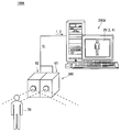
- FIG. 1 is a diagram illustrating a schematic configuration of an image processing system 100A using an image processing apparatus 200A according to the embodiment.
- the image processing system 100A mainly includes a stereo camera 300 and an image processing apparatus 200A.
- the image processing apparatus 200A acquires the input image 1 that is the first image and the input image 2 that is the second image (FIGS. 1 and 2) acquired by photographing the subject 70 with the stereo camera 300.
- the image processing apparatus 200A processes the input images 1 and 2 to perform color matching processing between the input images 1 and 2.
- the image processing apparatus 200A generates output images 3 and 4 (FIGS. 1 and 2) constituting the stereoscopic image 29 by the color matching process.
- the generated stereoscopic image 29 is displayed on the display unit 43 (FIG. 2) of the image processing apparatus 200A.
- the stereo camera 300 mainly includes a first camera 61 and a second camera 62. Further, each of the first camera 61 and the second camera 62 mainly includes a photographing optical system (not shown) and a control processing circuit having a color image sensor. The first camera 61 and the second camera 62 are provided with a predetermined base line length, and digital information is obtained by processing light ray information from a subject incident on the photographing optical system in synchronization with a control processing circuit or the like. Input images 1 and 2 which are color images are generated. The image size of the input images 1 and 2 is a predetermined size such as 3456 pixels ⁇ 2592 pixels, for example, and the input images 1 and 2 constitute a stereo image of the subject 70.
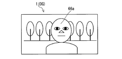
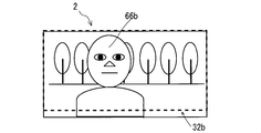
- FIGS. 3 and 4 are diagrams showing examples of the input image 1 and the input image 2, respectively.
- the input images 1 and 2 each photograph a common subject including a foreground subject and a distant subject.
- the foreground subject image 66a (FIG. 3) is the image of the foreground subject in the input image 1
- the foreground subject image 66b (FIG. 4) is the image of the foreground subject in the input image 2.
- the background of the foreground subject is photographed as a background subject image in each of the vicinity of the foreground subject image 66a in the input image 1 and the periphery of the foreground subject image 66b in the input image 2.
- the usefulness of the present invention is not impaired.
- the optical performances of the photographing optical systems of the first camera 61 and the second camera 62 are different from each other, the usefulness of the present invention is not impaired.
- the optical performance includes, for example, OTF (Optical Transfer function), photographing magnification, aberration, and shading characteristics.
- the stereo camera 300 can generate a plurality of input images 1 and a plurality of input images 2 by continuously photographing the subject in time sequence while synchronizing the first camera 61 and the second camera 62. It may be a configuration.
- FIG. 2 is a functional block diagram illustrating a configuration example of a main part of the image processing apparatus 200A according to the embodiment.
- the image processing apparatus 200 ⁇ / b> A mainly includes a CPU 11 ⁇ / b> A, an input / output unit 41, an operation unit 42, a display unit 43, a ROM 44, a RAM 45, and a storage device 46. This is realized by executing a program on a computer.
- the input / output unit 41 includes an input / output interface such as a USB interface or a Bluetooth (registered trademark) interface, an interface for connecting to a LAN or the Internet such as a multimedia drive and a network adapter, and the like. Exchange data between the two.
- the input / output unit 41 supplies, for example, various control signals for the CPU 11A to control the stereo camera 300 to the stereo camera 300 connected to the input / output unit 41 via the communication line DL or the like. To do.
- the input / output unit 41 supplies the input image 1 and the input image 2 captured by the stereo camera 300 to the image processing apparatus 200A.
- the input / output unit 41 also supplies the input image 1 and the input image 2 to the image processing apparatus 200A by receiving a storage medium such as an optical disk in which the input image 1 and the input image 2 are stored in advance.
- the operation unit 42 includes, for example, a keyboard or a mouse. When the operator operates the operation unit 42, setting of various control parameters for the image processing apparatus 200A and various operation modes of the image processing apparatus 200A are performed. Settings are made.
- the functional unit of the image processing apparatus 200 ⁇ / b> A is configured to perform processing according to each operation mode set from the operation unit 42.
- the display unit 43 is configured by, for example, a liquid crystal display screen for 3D display corresponding to a 3D display system such as a parallax barrier system.
- the display unit 43 includes an image processing unit (not shown) that converts the stereoscopic image 29 constituted by the output image 3 and the output image 4 into an image format corresponding to the three-dimensional display method in the display unit 43.
- the display unit 43 displays the stereoscopic image on which the necessary conversion processing has been performed by the image processing unit on the display screen.
- the left-eye image and the right-eye image are alternately switched at a high speed and displayed on the display unit 43, and each shutter corresponding to the left eye and the right eye is synchronized with the switching.
- a three-dimensional display method may be employed in which a stereoscopic image displayed on the display unit 43 is observed through dedicated glasses that can be alternately opened and closed.
- the display unit 43 displays an image supplied from the stereo camera 300, an image generated by the image processing device 200A, various setting information about the image processing device 200A, a control GUI (Graphical User Interface), and the like as a two-dimensional image. Or as character information so that it can be viewed by an observer.
- GUI Graphical User Interface
- ROM (Read Only Memory) 44 is a read-only memory and stores a program PG1 for operating the CPU 11A.
- a readable / writable nonvolatile memory (for example, a flash memory) may be used instead of the ROM 44.
- a RAM (Random Access Memory) 45 is a readable / writable volatile memory, and an image storage unit that temporarily stores various images acquired by the image processing device 200A, a stereoscopic image 29 generated by the image processing device 200A, and the like. It functions as a work memory that temporarily stores processing information of the CPU 11A.
- the storage device 46 is configured by, for example, a readable / writable nonvolatile memory such as a flash memory, a hard disk device, or the like, and permanently records information such as various control parameters and various operation modes of the image processing device 200A.
- a CPU (Central Processing Unit) 11A is a control processing device that controls and controls each functional unit of the image processing device 200A, and executes control and processing according to the program PG1 and the like stored in the ROM 44. As will be described later, the CPU 11A also functions as an image acquisition unit 12 that is an acquisition unit and an image processing unit 13 that is a processing unit. Using these functional units, the CPU 11A changes the frequency distribution of the histogram (first histogram) for the pixel representation information of the input image 1 to the frequency distribution of the histogram (second histogram) for the pixel representation information of the input image 2. To make a relatively close conversion.
- the CPU 11A performs a color matching process for bringing the color data (color information) of the input image 1 closer to the color data (color information) of the input image 2 by the conversion. Then, the CPU 11A generates output images 3 and 4 by the color matching process. In addition, the CPU 11A controls the imaging operation of the stereo camera 300 and controls the display unit 43 to display various images, calculation results, various control information, and the like on the display unit 43.
- each of the CPU 11A, the input / output unit 41, the operation unit 42, the display unit 43, the ROM 44, the RAM 45, the storage device 46, and the like are electrically connected via a signal line 49. Therefore, for example, the CPU 11A can execute control of the stereo camera 300 via the input / output unit 41, acquisition of image information from the stereo camera 300, display on the display unit 43, and the like at a predetermined timing.
- each function unit such as the image acquisition unit 12 and the image processing unit 13 is realized by executing a predetermined program by the CPU 11A. For example, it may be realized by a dedicated hardware circuit.
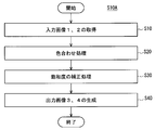
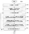
- FIG. 34 is a diagram illustrating an example of an outline of the operation flow S10A of the image processing apparatus 200A according to the embodiment.
- the image acquisition unit 12 of the image processing apparatus 200A acquires the input images 1 and 2 respectively acquired by the stereo camera 300 by receiving a user operation using the operation unit 42 (step S10 in FIG. 34).
- the input images 1 and 2 are images in which the subject is captured by the first camera 61 and the second camera 62 which are different imaging systems.
- the image processing unit 13 compares the histogram frequency distribution for the pixel representation information of the input image 1 with respect to the histogram frequency distribution for the pixel representation information of the input image 2.
- a color matching process for making the color data (color information) of the input image 1 relatively close to the color data (color information) of the input image 2 is performed (step S20 in FIG. 34).
- any one of the RGB components, brightness, and saturation in the image is also referred to as “pixel expression information”.
- the image processing unit 13 uses the one of the input images 1 and 2 that has a lower saturation degree that represents a ratio of pixels in which the pixel expression information (RGB component) is saturated. Saturation correction processing is performed to bring the saturation level of the second image closer to that of the other image (step S30 in FIG. 34), and output images 3 and 4 are generated (step S40 in FIG. 34).
- the image processing apparatus 200A performs a color matching process between the input image 1 and the input image 2 based on the histogram of the pixel expression information of the input images 1 and 2.
- a cumulative histogram that expresses a relationship between an input value and a cumulative frequency (cumulative pixel number) corresponding to the input value, an input value, and a frequency (pixel number) corresponding to the input value.
- the latter histogram is also referred to as “normal histogram” or “non-cumulative histogram” as appropriate.
- the term “histogram” is simply used as a general term for a cumulative histogram and a normal histogram (non-cumulative histogram).
- the image processing apparatus 200A performs, for example, a conversion that approximates the histograms of both images (a conversion that roughly matches the shape of the histograms) even when the hues of the input images 1 and 2 are different due to differences in white balance settings.
- the colors of both images can be brought close to each other.
- the image processing apparatus 200A first generates a conversion gamma table that converts the color information of the input images 1 and 2 so that the histograms of the pixel representation information of the input images 1 and 2 are relatively close to each other. To do. Then, the image processing apparatus 200A performs color matching processing of the input images 1 and 2 by converting the color information of the input images 1 and 2 using the conversion gamma table.
- the conversion gamma table will be described later.
- the histograms of the input images 1 and 2 are normalized by the number of pixels of each image and then used for processing for relatively bringing the histograms closer together. . Therefore, even if the numbers of pixels of the input images 1 and 2 are different from each other, the usefulness of the present invention is not impaired.
- a calibration chart dedicated to color matching processing is not necessary. Therefore, color calibration at the time of production of the stereo camera 300 is not necessary, and it is possible to perform color matching processing every time the subject is photographed by the stereo camera 300 regardless of variations in the illumination conditions of the subject. Become.
- the image processing apparatus 200A Prior to the start of the color matching process, the image processing apparatus 200A generates a target image derived from at least one of the input images 1 and 2 from at least one of the input images 1 and 2, and performs the target in the above-described process of approximating the histogram. Is used as a target image to give a histogram.
- the target image may be one of the input images 1 and 2 itself. Further, the target image may be generated based on the input images 1 and 2 such as an image obtained by averaging the pixel values of the input images 1 and 2. In addition, even if another subject imaged in advance for the same subject as the input images 1 and 2 is set as a target image, the usefulness of the present invention is not impaired.
- the image processing apparatus 200A may perform a process of bringing one of the input images 1 and 2 closer to the other histogram, or may convert both of the histograms of the input images 1 and 2 into a histogram for another image. There is also a case where a process of approaching is performed.
- an image that is not set as the target image among the input images 1 and 2 is also referred to as a “target image”.
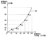
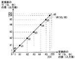
- FIG. 8 is a diagram showing an example of the cumulative histogram of the target image, and the cumulative histograms CH1 and CH2 are cumulative histograms for the R component values (R values) of the input images 1 and 2, respectively.
- the cumulative histogram CHT is a cumulative histogram for the R value of another image (target image) generated based on the input images 1 and 2.
- the image processing unit 13 of the image processing apparatus 200A sets both the input images 1 and 2 as target images. Then, the image processing unit 13 generates a conversion gamma table for each of the input images 1 and 2 that provides conversion for bringing the cumulative histograms CH1 and CH2 closer to the cumulative histogram CHT.
- the image processing unit 13 sets, as the target image, one of the input images 1 and 2 that has less color cast according to a preset operation mode.
- the image processing unit 13 uses the technique disclosed in Japanese Patent Laid-Open No. 2001-229374, for example, to calculate the feature amount of the signal distribution of the pixel representation information for each image data of the input images 1 and 2. Based on this, it can function as a color fog amount determination unit (not shown) that determines the color fog amount of each image. Further, as a result of the determination of the color fog amount, the image processing unit 13 can also function as a target image specifying unit (not shown) that uses the image with the smaller color fog amount of the input images 1 and 2 as the target image.
- the image processing unit 13 sets, as the target image, an image having a higher resolution of the imaging system related to shooting among the input images 1 and 2 according to a preset operation mode. That is, for example, when the first camera 61 of the first camera 61 and the second camera 62 has a higher resolution of the photographing optical system, the image processing unit 13 selects the image (input image) of the first camera 61. By specifying 1) as a target image, a target image is generated.
- An imaging system with a high resolution that is, an imaging system with a large number of pixels, generally uses lenses and processing circuits that have various optical performances better than an imaging system with a low resolution, that is, an imaging system with a small number of pixels. Accordingly, the image quality of the captured image, such as aberration and the presence or absence of false color, is better for the image captured by the imaging system having a higher resolution. Therefore, if the image with the higher resolution of the imaging system is set as the target image, the result of the color matching process of the input images 1 and 2 can be further improved.
- the image processing unit 13 can also select and specify the target image based on information for the user to specify the target image using the operation unit 42 according to the operation mode.
- FIG. 35 is a diagram illustrating an example of an operation flow S100A related to color matching processing using a cumulative histogram of the image processing apparatus 200A according to the embodiment.
- each pixel expression information of an image is expressed by 8 bits.
- FIG. 5 is a diagram for explaining the generation process of the conversion gamma table using the cumulative histogram.
- the conversion gamma table generation process for the R component (R value) of the image is described as an example.
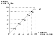
- FIG. 6 is a diagram showing an example of the R value conversion gamma table UR of the input image 1 (target image OG), and FIG. 7 shows the R value conversion of the input image 2 (target image TG). It is a figure which shows one example of the gamma table VR.
- the image processing unit 13 sets the RGB components for each of the input images 1 and 2.
- a cumulative histogram is acquired (step S120 in FIG. 35).
- an R value cumulative histogram CH1 of the input image 1 and an R value cumulative histogram CH2 of the input image 2 are shown.
- the cumulative histograms CH1 and CH2 are normalized by the maximum cumulative frequency.
- the image processing unit 13 acquires a cumulative histogram of RGB components for the target image TG, that is, the input image 2 (step S130 in FIG. 35).
- the cumulative histogram CHT of the R value of the target image TG is also a cumulative histogram CH2.
- the image processing unit 13 When the cumulative histogram of each color component for each of the target image OG and the target image TG is acquired, the image processing unit 13 generates a conversion gamma table for each RGB component for the input images 1 and 2 (FIG. 35 step S140).
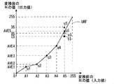
- step S140 the image processing unit 13 displays a plurality of points such as points Pa1 to Pa5 on the cumulative histogram CH1. Set a point.
- the R values at points Pa1 to Pa5 are A1 to A5, respectively.
- the image processing unit 13 specifies the points Pb1 to Pb5 on the cumulative histogram CH2 corresponding to the points Pa1 to Pa5, respectively, using the cumulative frequency value as a correspondence index. Get by.
- the cumulative frequencies of the R values of the points Pa1 to Pa5 are respectively equal to the cumulative frequencies of the R values of the points Pb1 to Pb5.
- the image processing unit 13 uses the cumulative frequency value as the association index, and associates the combination of the pixel representation information value of the cumulative histogram CH1 and the pixel representation information value of the cumulative histogram CH2 with the cumulative frequency. Get for each of multiple values of.
- the image processing unit 13 sets the points c1 to C5 corresponding to the R values A1 to A5 of the input image 1 and the R values B1 to B5 of the input image 2 as shown in FIG. c5 is specified. Then, the image processing unit 13 specifies an input / output relationship that associates each R value (input value) of the input image 1 with each R value (output value) of the output image 3 based on the points c1 to c5.
- the specified input / output relationship (also referred to as “conversion characteristic”) is also referred to as “conversion gamma table”.
- the conversion gamma table UR is specified as, for example, a polygonal line passing through the points c1 to c5 or an approximate curve. For example, when the R value is 8 bits, the conversion gamma table UR is generated so that the input value 0 corresponds to the output value 0 and the input value 255 corresponds to the output value 255.
- the conversion gamma table for other pixel expression values is generated in the same manner.
- the input image 2 is the target image TG
- the input image 2 is generated as it is as the output image 4.
- the conversion gamma table VR for the input image 2 is a straight line having a slope of 1 as specified by the points d1 to d5 in FIG.
- a non-conversion conversion gamma table is created.
- the conversion gamma table UR for converting the input image 1 into the output image 3 includes the value of the cumulative histogram CH1 of the R value of the input image 1 (target image OG) and the input image 2 (target image TG).
- the conversion characteristics are specified so that the cumulative histogram CH2 of R values approaches each other.
- the image processing unit 13 uses the generated conversion gamma tables for each of the RGB of the input images 1 and 2.
- output images 3 and 4 are respectively generated (step S150 in FIG. 35), and the color matching process is terminated.
- the value of the pixel expression information and the cumulative frequency corresponding to the value have a one-to-one correspondence. Therefore, as described above, if a cumulative histogram is used, for example, by specifying a plurality of points other than feature points such as peaks on the cumulative histogram, the cumulative histogram of the target image OG and the target image TG are accumulated.
- the histogram can be relatively close.
- each cumulative histogram is made closer based on a plurality of points, if the cumulative histogram is used, for example, color matching can be performed more accurately than when a normal histogram is used.
- color matching processing is performed using any one of RGB components as pixel expression information, in order to maintain the balance of the RGB color components, the color matching processing is also performed on the other components of the RGB components. Done.
- FIG. 9 is a diagram for explaining the generation process of the conversion gamma table UR (FIG. 10) using the non-cumulative histograms H1 and H2.
- the non-cumulative histogram H1 is a non-cumulative histogram of the input image 1 (target image OG).
- the non-cumulative histogram H2 is a non-cumulative histogram of the input image 2. Since the input image 2 is also the target image TG, the non-cumulative histogram H2 is also a non-cumulative histogram HT.
- the point Q1 is a point that gives a frequency peak value in the non-cumulative histogram H1
- the point Q2 is a point that gives a frequency peak value in the non-cumulative histogram H2.
- the R value a is an R value corresponding to the point Q1
- the R value b is an R value corresponding to the point Q2.
- FIG. 10 is a diagram illustrating an example of the R value conversion gamma table UR of the target image OG (input image 1).
- the conversion gamma table UR has an input / output relationship (conversion characteristics) for converting the R value of the input image 1 into the R value of the output image 3.
- the image processing unit 13 When the operation mode in which the non-cumulative histogram is used for generating the conversion gamma table is set, the image processing unit 13 generates the conversion gamma table based on the feature points such as the points Q1 and Q2. More specifically, the image processing unit 13 first specifies a point Q3 corresponding to the R value a before conversion and the R value b after conversion, as shown in FIG. Next, the conversion gamma table UR is generated by specifying a broken line (curve) connecting the point Q3 with each of the points (0, 0) and (255, 255). As a feature point on the non-cumulative histogram used for generating the conversion gamma table, for example, a feature point that gives a peak value or other extreme values can be used.
- the conversion gamma table when the conversion gamma table is generated based on the non-cumulative histogram, the conversion gamma table that brings the histograms of the pixel representation information of the input images 1 and 2 closer to each other is the non-cumulative histogram. Generated based on feature points. Also, the degree of color data matching between the output images 3 and 4 is improved by the generated conversion gamma table as compared with the color data matching between the input images 1 and 2. Therefore, even if the conversion gamma table is generated using a non-cumulative histogram, the usefulness of the present invention is not impaired.
- FIG. 36 is a diagram illustrating an example of an operation flow S200A in which the image processing apparatus 200A according to the embodiment performs color matching processing of the input images 1 and 2 as pixel representation information relating to generation of a conversion gamma table. is there. Note that the operation flow shown in FIG. 36 is the same processing as the case where each component of RGB, which is the pixel expression information of the operation flow shown in FIG. 35, is replaced with saturation, except for the processing in steps S220 and S270. Is done by.
- the image processing unit 13 acquires the input images 1 and 2 (step S210). Next, the image processing unit 13 converts the color space of the input images 1 and 2 from RGB to LCH (lightness, saturation, hue) (step S220), and the input image 1 and 2 have a C (saturation) component. Is acquired (step S230).
- the image processing unit 13 acquires the cumulative histogram of the C (saturation) component for the target image that is generated or specified in advance (step S240).
- the image processing unit 13 generates a C component conversion gamma table for each of the input images 1 and 2 in the same manner as in step S140 (FIG. 35) (step S250). Using each of the generated conversion gamma tables, the C components of the input images 1 and 2 are converted (step S260).
- the image processing unit 13 When the conversion is completed, the image processing unit 13 generates the output images 3 and 4 by inversely converting the color spaces of the input images 1 and 2 in which the C components are converted from LCH to RGB (step S270). ), The color matching process is terminated. Note that the color matching process may be performed based on both L (lightness) and C (saturation), for example.
- the image processing unit 13 When performing the color matching process a plurality of times in different color spaces, the image processing unit 13 first represents pixel information of any one of the RGB components, lightness, and saturation for the input images 1 and 2. A first color matching process is performed as information. Next, the image processing unit 13 sets pixel information other than the information used for the first color matching process among the RGB components, lightness, and saturation of the input images 1 and 2 on which the color matching process has been performed. A second color matching process is performed as expression information.
- the image processing unit 13 first performs color matching processing for each of the RGB color components according to the operation flow of FIG. 35, and then based on the C (saturation) component according to the operation flow of FIG. Perform color matching processing. Conversely, even if color matching processing based on pixel representation information other than RGB components is performed and then color matching processing based on RGB components is performed, the usefulness of the present invention is not impaired.
- the color matching process between the input images 1 and 2 is performed a plurality of times in different color spaces, for example, compared to the case where only the color matching process is performed in each RGB color space, the output image after conversion The degree of color matching between 3 and 4 is further improved.
- one part of the image area of the input image 1 and a part of the image area of the input image 2 need only include the same part on the subject.
- the partial area size of the input image 2 may be different from the partial area size of the input image 2. For example, when a partial area that requires color matching processing is set as a target for color matching processing among the image areas of the input images 1 and 2, color matching processing is performed based on a histogram for the entire image area. Compared with the case where the color matching process is performed, the color matching process between the partial areas where the color matching process is required can be further improved.
- the image processing unit 13 acquires region information specified by the user operating the operation unit 42 according to the operation mode as a partial region related to the generation of the histogram, and the input image 1,
- the area information is generated on the basis of the image information of No. 2. Note that even if the conversion gamma table acquired based on the histogram of the partial area is applied not only to the partial area but also to other areas such as the entire image area, the usefulness of the present invention is impaired. It is not a thing.
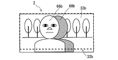
- FIGS. 11 and 12 are diagrams illustrating examples of the common areas 32a and 32b in the input images 1 and 2 when the input images 1 and 2 have vertical parallax, for example.
- the common area 32a is an area enclosed by a broken-line rectangle in the input image 1
- the common area 32b is an area enclosed by a broken-line rectangle in the input image 2.
- the common areas 32a and 32b are areas related to images obtained by capturing the same part of the subject in the input images 1 and 2, respectively. That is, the image of the input image 1 in the common area 32a and the image of the input image 2 in the common area 32b are partial images respectively corresponding to the same part of the subject.
- the image processing unit 13 is common by acquiring the region information of the common region specified by the user via the operation unit 42 or the region information of the common region generated at the time of stereo calibration of the stereo camera 300 according to the operation mode.
- the areas 32a and 32b are specified. Further, the image processing unit 13 identifies the common areas 32a and 32b by generating area information of the common area based on the result of the pattern matching process between the input images 1 and 2 according to the operation mode.
- an NCC Normalized Cross Correlation
- SAD Sum of Absolute Difference
- POC Phase Only Correlation
- Stereo calibration is performed in advance for the stereo camera 300, and each calibration image obtained by photographing the calibration chart by the first camera 61 and the second camera 62 under a predetermined photographing condition is used for stereo calibration. .
- stereo camera calibration a common area between images is specified for each calibration image, and parameters used for image aberration removal processing, parallelization processing, and the like are obtained.
- the obtained parameters and area information for specifying a common area between the calibration images are stored in the storage device 46.
- the image processing unit 13 specifies the common areas 32 a and 32 b for the input images 1 and 2 by acquiring area information about the common areas stored in advance in the storage device 46.
- FIG. 13 is a diagram illustrating an example of a partial region 33a in which the shaded occlusion region 68a (first occlusion region) is excluded from the common region 32a of the input image 1 in addition to FIG.
- FIG. 14 is a diagram illustrating an example of a partial region 33b in which the shaded occlusion region 68b (second occlusion region) is excluded from the common region 32b of the input image 2 in addition to FIG. .
- the occlusion area 68a is an area of an image of a distant subject that can be photographed by the first camera 61 but cannot be photographed by the second camera 62 because of the foreground subject related to the foreground subject image 66a.
- the occlusion area 68b is an area of an image of a distant subject that can be photographed by the second camera 62 but cannot be photographed by the first camera 61 due to the foreground subject related to the foreground subject image 66b.
- the image processing unit 13 When the operation mode of the image processing apparatus 200A is set to the operation mode corresponding to the color matching process based on the partial image excluding the occlusion area, the image processing unit 13 performs, for example, between the input images 1 and 2.
- the occlusion areas 68a and 68b are specified by performing the corresponding point search process in FIG.
- the corresponding point search process may be performed by a process of specifying representative points of the regions that are associated with each other by a pattern matching process using a correlation calculation method such as the SAD method or the POC method.
- the image processing unit 13 performs color matching processing by conversion that brings the histograms of the identified partial areas 33a and 33b closer to each other.
- the shapes of the generated histograms are closer to each other than when the occlusion area is used. It becomes. Therefore, according to the color matching process, it is possible to further improve the degree of color matching between images.
- the partial image excluding the occlusion area in addition to the image of the area excluding the occlusion area from the common area, for example, even if the partial image excluding the occlusion area from the entire input image is adopted, the usefulness of the present invention Is not detrimental.
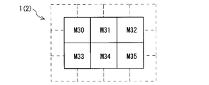
- FIG. 15 is a diagram illustrating an example of a plurality of partial areas (also referred to as “blocks”) set in each of the input images 1 and 2.
- 12 blocks M1 to M12 are set.
- the image processing unit 13 performs color matching processing using a plurality of divided partial areas according to the operation mode of the image processing apparatus 200A. In the color matching process, the image processing unit 13 divides each image area of the input images 1 and 2 into a plurality of blocks (M1 to M12) as illustrated in FIG.
- the image processing unit 13 includes a target block among the blocks obtained by dividing the image area of the input image 1 and a corresponding block whose arrangement relationship corresponds to the target block among the blocks obtained by dividing the image area of the input image 2. Identify each. When the target block and the corresponding block are identified, the image processing unit 13 compares the histogram frequency distribution for the pixel expression information of the target block with respect to the histogram frequency distribution for the pixel expression information of the corresponding block. A conversion gamma table that is close to the target block is generated for each of the target block and the corresponding block.
- the image processing unit 13 applies a corresponding conversion gamma table to each of the target block and the corresponding block, and converts the value of the pixel expression information, so that the block between the target block and the corresponding block is converted.
- Color matching processing that is, color matching processing for each block is performed.
- the image processing unit 13 performs the color matching process between the input images 1 and 2 by performing the color matching process while changing the combination of the target block and the corresponding block.
- color matching processing is performed between blocks corresponding to each other. Therefore, for example, even when shading occurs in the input images 1 and 2, the degree of color matching after the color matching process can be further improved as compared with the case where the color matching process is performed based on the histogram for the entire image. .
- the image processing unit 13 weights the conversion gamma table of each block for each of the input images 1 and 2 according to the distance between the blocks for each of the input images 1 and 2 according to the operation mode. By applying, a new conversion gamma table for each block is obtained.
- the image processing unit 13 performs color matching processing on the input images 1 and 2 by converting the values of the pixel expression information of each block based on the acquired new conversion gamma table for each of the input images 1 and 2. I do.
- FIG. 37 and 38 are diagrams showing an example of an operation flow S300A in which the image processing apparatus 200A performs color matching processing using weighting processing for the input images 1 and 2 divided into a plurality of partial regions, respectively.
- FIG. 16 is a diagram for explaining an example of weights applied to each partial region, and w5 to w7 are blocks M5 to W7 applied to respective positions in the + X direction (FIG. 15) in the block M6. The respective weights of M7 are shown.
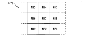
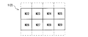
- FIGS. 17 to 19 are diagrams showing blocks M13 to M21, blocks M22 to M29, and blocks M30 to M35, which are examples of a plurality of divided regions (blocks) in the input images 1 and 2, respectively.
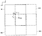
- FIG. 20 is a diagram for explaining an example of weighting processing in a plurality of partial areas using blocks M1, M13, M22, and M30. In FIG. 20, for the sake of convenience, the overlapping portions of the outer edges of the blocks M1, M13, M22, and M30 are shifted and displayed for the sake of convenience.
- the point PO1 is a central point in the area of the block M1.
- the operation flow S300A of FIGS. 37 and 38 will be described below with reference to FIGS. 15 to 20 as appropriate.
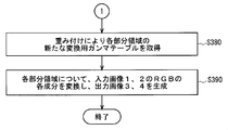
- the image processing unit 13 acquires the input images 1 and 2 (step S310), and each of the input images 1 and 2 is, for example, a plurality of partial areas as illustrated in FIG. It is divided into (blocks) (step S320). Next, the image processing unit 13 selects one partial area among the plurality of partial areas (step S330). When the selection of the partial region is completed, the image processing unit 13 acquires a cumulative histogram of each RGB component of the selected partial region for each of the input images 1 and 2 (step S340).
- the image processing unit 13 acquires a cumulative histogram of each component of RGB for a target image that is generated or specified in advance (step S350). For example, the image processing unit 13 acquires a new cumulative histogram CH6_N of the block M6 calculated by the expression (1) as a cumulative histogram of the block M6, and similarly acquires a cumulative histogram for other blocks.
- the image processing unit 13 When the cumulative histogram is acquired, the image processing unit 13 generates a conversion gamma table for each component of RGB in the partial area selected for each of the input images 1 and 2 in the same manner as in step S140 (FIG. 35). Generate (step S360).
- step S370 the image processing unit 13 checks whether or not selection of all partial areas has been completed. As a result of the confirmation in step S370, if selection of all partial areas has not been completed, the image processing unit 13 returns the process to step S330.
- the image processing unit 13 acquires a new conversion gamma table for each partial area by weighting (step S380). Specifically, for example, for the block M6, the image processing unit 13 acquires a new conversion gamma table UR6_N calculated by Expressions (2) to (4), and newly creates other blocks in the same way. Get a cumulative histogram. However, if the block to be processed is an area at the end of the area of the input image, a new conversion gamma is obtained from each expression corresponding to Expressions (2) to (4) based only on the actual block. Calculate the table.
- a generation method according to the division mode in which the input images 1 and 2 are divided into a plurality of partial regions is employed.
- the image processing unit 13 selects blocks M1 to M12 (FIG. 15), blocks M13 to M21 (FIG. 17), blocks M22 to 29 (FIG. 18), and blocks M30 to M35 (step S320). Each division of FIG. 19) is performed.
- the image processing unit 13 obtains a cumulative histogram by the expression (1), and for each of the blocks M13 to M35, for example, the block M13 calculated by the expression (5).
- a new cumulative histogram CH13_N is acquired as the cumulative histogram of the block M13, and the cumulative histogram is acquired in the same manner for the other blocks.
- the image processing unit 13 acquires the conversion gamma table UR_PO2 calculated by the equation (6) for the point PO2 in the block M1.
- the image processing unit 13 obtains the conversion gamma table for the block M1 by calculating the conversion gamma table in the same manner for other points of the block M1.
- the image processing unit 13 also generates a conversion gamma table for the blocks M2 to M12 in the same manner as the block M1.
- the image processing unit 13 uses the values of RGB components of the input images 1 and 2 for each partial area for a new conversion for each partial area.
- output images 3 and 4 are generated (step S390), and the color matching process is terminated.
- the conversion gamma table is generated by the weighting process, it is possible to further suppress the rapid variation of the color data at the boundary portion of the divided partial area compared to the case where the weighting process is not performed. Become. However, even if the weighting process is performed or not performed, the usefulness of the present invention is not impaired.
- the image processing unit 13 further calculates the saturation degree of one of the images having a lower saturation degree representing the ratio of the pixels in which the pixel expression information values are saturated in the input images 1 and 2. Then, a saturation correction process is performed to bring the other image closer to the saturation level.
- saturation means that the value of the pixel representation information is an upper limit value of a range that can be expressed by a predetermined number of bits (also referred to as “representable range”), and Both indicate the lower limit.
- the upper limit of the target image OG is obtained by the process of step S140 in FIG.
- a conversion gamma table for increasing the value of the pixel representation information on the side is generated.
- the conversion table is applied as it is to the target image OG, the converted image of the target image OG has a large degree of discreteness in the range distribution on the upper limit side of the representable range, and the value of the pixel expression information changes.
- the boundary portion is conspicuous. This phenomenon occurs due to, for example, interpolation processing when generating the conversion gamma table. More specifically, the boundary portion is generated when a portion where the value of the pixel expression information after conversion is 255 and a portion where the value is 250, for example, are adjacent to each other.
- the lower limit side pixel expression information of the target image OG A conversion gamma table for reducing the value is generated.
- the conversion table is applied as it is to the target image OG, the converted image of the target image OG has a high degree of discreteness of the range distribution on the lower limit side of the representable range, and the value of the pixel expression information changes.
- the boundary portion is conspicuous. More specifically, the boundary portion is generated when a portion where the value of the pixel expression information after conversion is 0 and a portion where the value is 5 or the like are adjacent to each other.
- the image processing apparatus 200A performs a saturation correction process for further saturating the target image OG based on the image information of the target image TG for the target image OG and the target image TG saturated with the target image OG. This increases the possibility of improving the phenomenon in which the boundary portion (also referred to as “color step”) is noticeable.
- FIG. 39 is a diagram illustrating an example of an operation flow S400A in which the image processing apparatus 200A acquires a conversion gamma table related to saturation correction processing.
- the image processing unit 13 first acquires the saturation for the input images 1 and 2 (step S142).
- 21 to 24 are diagrams for explaining an example of the degree of saturation acquired based on the conversion gamma table. As described above, these conversion gamma tables are generated based on the target image TG and the target image OG that is saturated with respect to the target image TG.
- the conversion gamma table UR (UG, UB) in FIG. 21 (22, 23) is for conversion of the R (G, B) component of the input image 1 (target image OG) generated in step S140 of FIG. It is a gamma table.
- the conversion gamma table VR (VG, VB) in FIG. 24 is a conversion gamma table for the R (G, B) component of the input image 2 (target image TG).
- Each conversion gamma table VR, VG, VB has a conversion characteristic equal to each other, and has a slope of 1.
- Points e0 to e6 on the conversion gamma table UR correspond to R values (input values) 1, A1 to A5, and 254 before conversion, respectively, and R values after conversion (output) Value) BR0 to BR6 correspond to each.
- G values (input values) 1, A1 to A5, and 254 before conversion correspond to points f0 to f6 on the conversion gamma table UG (FIG. 22), respectively, and the G value after conversion.
- (Output values) BG0 to BG6 correspond to each.
- points g0 to g6 on the conversion gamma table UB correspond to B values (input values) 1, A1 to A5, and 254 before conversion, respectively, and B values after conversion.
- (Output values) BB0 to BB6 correspond to each other.
- R (G, B) values (input values) 1, A1 to A5, and 254 before conversion correspond to points d0 to d6 on the conversion gamma table VR (VG, VB) in FIG.
- the values (output values) 1, A1 to A5, and 254 of R (G, B) after conversion correspond respectively.
- step 142 of FIG. 39 the image processing unit 13 outputs the output value of each conversion gamma table corresponding to each end of the input value range in each conversion gamma table UR (UG, UB, VR, VG, VB). Get saturation based on.
- the “end of the range” in the conversion gamma table generally includes a location (or range) corresponding to a value that is larger by a predetermined minute width from the lower limit of the range (0% in the case of a 100-percentage display), and the range.
- the image processing unit 13 employs the least significant bit (that is, 1) representing the R (G, B) value as the minute width, thereby allowing the end of the range.
- the values 1 (lower limit side) and 254 (upper limit side) are used.
- the image processing unit 13 outputs the output values BR6, BG6, BB6 corresponding to the input value 254 in each of the conversion gamma tables UR, UG, UB, VR, VG, and VB in FIGS. And 254, that is, the output value BR6 is acquired as the upper limit saturation. Further, the image processing unit 13 acquires the maximum value among the output values BR0, BG0, BB0, and 1 corresponding to the input value 1, that is, the output value BG0, as the lower limit saturation.
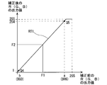
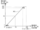
- the image processing unit 13 When the saturation level is acquired, the image processing unit 13 generates a correction table RT1 (FIG. 25) for correcting each conversion gamma table UR (UG, UB, VR, VG, VB) based on the acquired saturation level. Obtain (step S144).
- FIG. 25 is a diagram showing an example of a correction table RT1 for correcting the conversion gamma table.
- the point Q4 corresponds to the output value BG0 (value b) acquired as the lower limit saturation and the corrected output value 1.
- the point Q5 corresponds to the output value BR6 (value a) acquired as the upper limit saturation and the corrected output value 254.
- the image processing unit 13 sets the correction table RT1 based on the points Q4 and Q5. Specifically, for example, the correction table RT1 is set based on a straight line connecting the point Q4 and the point Q5 expressed by the equation (7). The upper limit of the output value after correction is 255.
- FIG. 26, FIG. 27, and FIG. 28 show the corrected gamma tables UR, UG, and UB for the R value, G value, and B value of the target image OG after correction by the correction table RT1, respectively. It is a figure which shows an example of the conversion gamma tables URF, UGF, and UBF. Further, FIG. 29 shows the conversion gamma after correction in which the conversion gamma tables VR, VG, and VB of the R value, G value, and B value for the target image TG itself are respectively corrected by the correction table RT1. It is a figure which shows an example of table VRF, VGF, and VBF.
- the image processing unit 13 corrects each conversion gamma table UR (UG, UB, VR, VG, VB) using the correction table RT1 (step S146 in FIG. 39). By the correction, the image processing unit 13 acquires the corrected conversion gamma tables URF (FIG. 26), UGF (FIG. 27), UBF (FIG. 28), VRF, VGF, and VBF (FIG. 29, respectively) and corrects them. The subsequent conversion gamma table acquisition process is terminated.
- Each of the conversion gamma tables before correction is corrected by the common correction table RT1, whereby generation of a color step in each conversion gamma table before correction can be suppressed.
- the points h0 to h5 in the conversion gamma table URF correspond to the points e0 to e6 (FIG. 21), respectively.
- points j0 to j6 in the conversion gamma table UGF correspond to points f0 to f6 (FIG. 22), respectively.
- the points k0 to k6 in the conversion gamma table UBF correspond to the points g0 to g6, respectively.
- points n0 to n5 in the conversion gamma table VRF correspond to points d0 to d5 (FIG. 24), respectively.
- the corrected conversion gamma tables URF, UGF, UBF, VRF, VGF, and VBF are respectively the conversion gamma tables UR, UG, UB, VR, and VG before correction. And conversion characteristics (input / output relationship) that saturate the image to be corrected more than VB.
- the input images 1 and 2 are converted using the obtained conversion gamma tables, respectively, so that color matching between the input images 1 and 2 is performed, and saturation in the converted output images 3 and 4 is performed. Color steps on the upper limit side and the lower limit side can be suppressed. Further, in the color matching, for example, even if there is a whiteout in one of the input images 1 and 2 due to a difference in exposure control during shooting between the first camera 61 and the second camera 62, for example. Color matching between the input images 1 and 2 can be performed.
- the color step at the upper limit side of saturation is more easily recognized than the color step at the lower limit side of saturation. Therefore, for example, even if the correction table RT1 is generated based only on the saturation level on the upper limit side of saturation, the usefulness of the present invention is not impaired. Further, even if the correction table RT1 is generated based only on the saturation level on the lower limit side of saturation according to the required specifications for the image processing apparatus 200A, the usefulness of the present invention is not impaired.
- the image processing unit 13 generates a similar correction table RT2 (FIG. 31) by using a histogram according to the operation mode. More specifically, the image processing unit 13 determines the frequency of the histogram corresponding to the end of the value range of the pixel representation information in the histogram for the pixel representation information of the image with the higher saturation of the input images 1 and 2. The saturation is acquired based on the above, and the saturation correction process is performed. Note that the image processing unit 13 acquires the degree of saturation in step 142 of FIG.
- the “end of the range” in the histogram generally includes a location (or range) corresponding to a value that is larger by a predetermined minute width from the lower limit of the range (0% in the case of a 100% display), and the upper limit of the range.
- the image processing unit 13 uses the value 0 (lower limit side) and 255 (upper limit side) as end portions of the range by adopting the value 0 as the minute width.
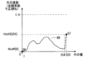
- FIG. 30 is a diagram for explaining an example of the degree of saturation acquired based on the non-cumulative histogram, and FIG. 30 shows a non-cumulative histogram HR for the R value.
- the R value corresponding to the point Q7 is 255, which is the upper limit value of the representable range, and the normalized frequency is HistR [255].
- the R value corresponding to the point Q6 is 0, which is the lower limit value of the representable range, and the normalized frequency is HistR [0].
- the image processing unit 13 acquires the saturation used to generate the correction table RT2 based on the non-cumulative histogram of each RGB component for each of the input images 1 and 2.
- the image processing unit 13 acquires the maximum value d among the frequencies at the end portion (lower limit side) of the range as the saturation degree for the end portion (lower limit side) of the range. Further, the image processing unit 13 acquires the maximum value c among the frequencies at the end portion (upper limit side) of the range as the saturation degree for the end portion (upper limit side) of the range.
- the image processing unit 13 uses the values 0 and 1 (lower limit side) and the values 254 and 255 (upper limit side) as end portions of the range, and based on the cumulative frequency of the cumulative histogram corresponding to each value.
- the maximum values c and d can be acquired. Therefore, the image processing unit 13 can also acquire the saturation (upper limit side and lower limit side) using the cumulative histogram.
- the image processing unit 13 corrects each conversion gamma table UR (UG, UB, VR, VG, VB) based on the acquired saturation level in step S144 of FIG.
- the table RT2 (FIG. 31) is acquired.
- FIG. 31 is a diagram showing an example of the correction table RT2 for correcting the conversion gamma table.
- the point Q8 corresponds to the output value d ⁇ 255 + 1 calculated based on the output value d acquired as the saturation at the end of the range (lower limit side), and the output value 1 after correction. Is a point.
- the point Q9 includes an output value (1-c) ⁇ 255-1, calculated based on the output value c acquired as the saturation at the end (upper limit side) of the range, and the corrected output value 254. It is a point corresponding to.
- the image processing unit 13 sets the correction table RT2 based on the points Q8 and Q9. Specifically, for example, the correction table RT2 is acquired based on a straight line connecting the point Q8 and the point Q9, which is expressed by the equation (8). The upper limit of the output value after correction is 255.
- the image processing unit 13 corrects the conversion gamma table for each of the RGB color components of the input images 1 and 2 using the correction table RT2, similarly to the correction table RT1 (FIG. 25). To do. Then, the image processing unit 13 converts the RGB color components of the input images 1 and 2 using the corrected conversion gamma tables, thereby performing the color matching process and the saturation correction process. Images 3 and 4 are generated.
- the correction table RT2 can also be generated by using the saturation obtained based on the histogram, and each conversion gamma table can be corrected.
- the image processing apparatus 200A is not limited to the image captured at a time different from the input images 1 and 2 to be subjected to color matching processing.
- the color matching process can be performed based on the input image.
- FIG. 32 is a diagram for explaining the concept of time-series images, and images fA to fF are time-series images that are continuously photographed at a predetermined frame rate. Note that the image fB is an image at the current time.
- FIG. 33 is a diagram showing a conversion gamma table URF for R values as an example of a conversion gamma table acquired based on a time-series image.
- Points s5, t5, and u5 are the R input value A5 and the R output values B5, C5, and D5 after conversion corresponding to the input value A5 in the conversion gamma tables for the images fB, fC, and fD, respectively.
- the point q5 is a point in which the input value A5 is associated with the average value AVE5 of the output values B5 to D5 calculated by the equation (9).
- the image processing unit 13 converts the average value of the output values of the conversion gamma table in each of the time-series images acquired by the equation (9) to each output after conversion in the new conversion gamma table URF for the current input image. By obtaining as a value, a conversion gamma table URF is generated.
- the histogram frequency distribution for the input image 1 is relative to the histogram frequency distribution for the input image 2 with respect to the input images 1 and 2 in which the subject is captured.
- the color matching process between the input image 1 and the input image 2 is performed. Since the color matching process does not require a dedicated calibration chart, it can be performed every time the subject is photographed. For this reason, regardless of the illumination conditions of the subject, color matching processing can be easily performed between the images in which the subject is captured.
- the above-described image processing system 100A has a configuration realized by the image processing apparatus 200A in the image processing system 100A executing a program with a general-purpose computer, but the image processing system 100A is replaced with the configuration.
- it may be realized as a system including a stereo camera 300 and an image processing device 200A in a device such as a digital camera, a digital video camera, or a portable information terminal.
- a conversion gamma table for color matching processing in which color matching processing and saturation correction processing are collectively performed is generated and applied to the input images 1 and 2. Even if the color matching process not including the degree correction process and the saturation correction process are sequentially performed, the usefulness of the present invention is not impaired.
- sequential processing for example, first, intermediate images are generated by applying a color matching process that does not include saturation correction processing to the input images 1 and 2, and then the color components of the intermediate images are generated. This is realized by, for example, processing for generating output images 3 and 4 whose saturation is corrected by applying a correction table such as the correction table RT1 (FIG. 25) and the correction table RT2 (FIG. 31).
Landscapes
- Engineering & Computer Science (AREA)
- Multimedia (AREA)
- Signal Processing (AREA)
- Health & Medical Sciences (AREA)
- Biomedical Technology (AREA)
- General Health & Medical Sciences (AREA)
- Image Processing (AREA)
- Facsimile Image Signal Circuits (AREA)
- Studio Devices (AREA)
- Processing Of Color Television Signals (AREA)
- Testing, Inspecting, Measuring Of Stereoscopic Televisions And Televisions (AREA)
- Color Television Image Signal Generators (AREA)
Abstract
Description
以下、本発明の一実施形態を図面に基づいて説明する。図面では同様な構成および機能を有する部分に同じ符号が付され、下記説明では重複説明が省略される。また、各図面は模式的に示されたものであり、例えば、各図面における画像上の表示物のサイズおよび位置関係等は必ずしも正確に図示されたものではない。なお、説明の便宜上、図15および図20には直交するXYの2軸が付されている。 <About embodiment>
Hereinafter, an embodiment of the present invention will be described with reference to the drawings. In the drawings, parts having the same configuration and function are denoted by the same reference numerals, and redundant description is omitted in the following description. Each drawing is schematically shown. For example, the size and positional relationship of the display object on the image in each drawing are not necessarily shown accurately. For convenience of description, two orthogonal XY axes are attached to FIGS. 15 and 20.
図1は、実施形態に係る画像処理装置200Aを用いた画像処理システム100Aの概略構成を示す図である。図1に示されるように、画像処理システム100Aは、ステレオカメラ300と画像処理装置200Aとを主に備えて構成されている。画像処理システム100Aでは、被写体70をステレオカメラ300が撮影することにより取得した第1画像である入力画像1および第2画像である入力画像2(図1、図2)を画像処理装置200Aが取得し、画像処理装置200Aが入力画像1および2を処理することによって入力画像1および2の間での色合わせ処理を行う。画像処理装置200Aは、該色合わせ処理により、立体画像29を構成する出力画像3および4(図1、図2)を生成する。生成された立体画像29は、画像処理装置200Aの表示部43(図2)に表示される。 <(1) About
FIG. 1 is a diagram illustrating a schematic configuration of an
図1に示されるように、ステレオカメラ300は、第1カメラ61と第2カメラ62とを主に備えて構成されている。また、第1カメラ61および第2カメラ62は、それぞれ、不図示の撮影光学系と、カラー撮像素子を有する制御処理回路とを主に備えて構成されている。第1カメラ61と第2カメラ62とは、所定の基線長を隔てて設けられており、撮影光学系に入射した被写体からの光線情報を制御処理回路等で同期して処理することによって、デジタルカラー画像である入力画像1および2を生成する。入力画像1および2の画像サイズは、例えば、3456画素×2592画素などの所定サイズであり、入力画像1および2は、被写体70のステレオ画像を構成する。 <(1-1)
As shown in FIG. 1, the
図2は、実施形態に係る画像処理装置200Aの要部の構成例を示す機能ブロック図である。図2に示されるように、画像処理装置200Aは、CPU11A、入出力部41、操作部42、表示部43、ROM44、RAM45および記憶装置46を主に備えて構成されており、例えば、汎用のコンピュータでプログラムを実行することなどによって実現される。 <(1-2) About
FIG. 2 is a functional block diagram illustrating a configuration example of a main part of the
<(2-1)動作の概要について>
図34は、実施形態に係る画像処理装置200Aの動作フローS10Aの概要の1例を示す図である。画像処理装置200Aの画像取得部12は、操作部42を用いたユーザの操作を受け付けることなどによって、ステレオカメラ300によってそれぞれ取得された入力画像1および2を取得する(図34のステップS10)。入力画像1、2は、互いに異なる撮像系である第1カメラ61および第2カメラ62によって被写体がそれぞれ撮影された画像である。 <(2) Operation of
<(2-1) Outline of operation>
FIG. 34 is a diagram illustrating an example of an outline of the operation flow S10A of the
画像処理装置200Aは、入力画像1、2の画素表現情報のヒストグラムに基づいて入力画像1と入力画像2との間での色合わせ処理を行う。なお、本願においては、入力値と、該入力値に対応する累積度数(累積画素数)との関係を表現する累積ヒストグラムと、入力値と、該入力値に対応する度数(画素数)との関係を表現するヒストグラムとを区別するために、後者のヒストグラムは、「通常のヒストグラム」、または「非累積ヒストグラム」とも適宜称される。 <(2-2) Color matching processing>
The
画像処理装置200Aは、色合わせ処理の開始に先立って、入力画像1、2の少なくとも一方から入力画像1、2のうち少なくとも一方から派生する目標画像を生成し、上述したヒストグラムを近づける処理において目標となるヒストグラムを与える目標画像として用いる。目標画像は、入力画像1、2のうち何れか一方自体であってもよい。また、目標画像は、例えば、入力画像1、2の画素値の平均を取った画像など、入力画像1および2に基づいて、生成されてもよい。また、入力画像1、2と同一の被写体が、予め撮影された別画像が目標画像として設定されたとしても本発明の有用性を損なうものではない。 <About target image settings>
Prior to the start of the color matching process, the
次に、図3、4に示されるように入力画像1が対象画像OGとして、また、入力画像2が目標画像TGとしてそれぞれ設定された場合を例として、累積ヒストグラムを使用した色合わせ処理について図35の動作フローを適宜参照しつつ説明する。図35は、実施形態に係る画像処理装置200Aの累積ヒストグラムを用いた色合わせ処理に係る動作フローS100Aの1例を示す図である。なお、本願においては、画像の各画素表現情報は、それぞれ8ビットで表現される。 <(2-2-1) Color matching processing using cumulative histogram>
Next, as shown in FIGS. 3 and 4, color matching processing using a cumulative histogram is illustrated with an example in which the
図9は、非累積ヒストグラムH1、H2を用いた変換用ガンマテーブルUR(図10)の生成処理を説明するための図である。非累積ヒストグラムH1は、入力画像1(対象画像OG)の非累積ヒストグラムであり。非累積ヒストグラムH2は、入力画像2の非累積ヒストグラムである。入力画像2は、目標画像TGでもあるので、非累積ヒストグラムH2は、非累積ヒストグラムHTでもある。 <(2-2-2) Color matching processing using non-cumulative histogram>
FIG. 9 is a diagram for explaining the generation process of the conversion gamma table UR (FIG. 10) using the non-cumulative histograms H1 and H2. The non-cumulative histogram H1 is a non-cumulative histogram of the input image 1 (target image OG). The non-cumulative histogram H2 is a non-cumulative histogram of the
次に、異なる色空間での複数回の色合わせ処理が行われる動作モードが設定されている場合の画像処理装置200Aの動作について説明する。該説明に先立って、上述したRGBの各成分における色空間とは異なる色空間における色合わせ処理について、C(彩度)が色空間として用いられる場合を説明する。 <(2-2-3) Multiple Color Matching Processes in Different Color Spaces>
Next, the operation of the
図3および図4にそれぞれ示された入力画像1、2においては、画像領域の全体における画素表現情報のヒストグラムが取得され、該ヒストグラムに基づいて、色合わせ処理が行われていた。しかしながら、入力画像1の画像領域の1部の画像と、入力画像2の画像領域の一部の画像とのそれぞれのヒストグラムに基づいて色合わせ処理が行われたとしても本発明の有用性を損なうものではない。 <(2-2-4) Color matching process using partial area>
In the
図11および図12は、例えば入力画像1および2に上下の視差があった場合の、入力画像1および2における共通領域32aおよび32bの1例をそれぞれ示す図である。共通領域32aは、入力画像1における破線の矩形によって内包された領域であり、共通領域32bは、入力画像2における破線の矩形によって内包された領域である。また、共通領域32aおよび32bは、入力画像1および2のうち被写体の同一部分をそれぞれ捉えた画像に係る領域である。すなわち、共通領域32aにおける入力画像1の画像と、共通領域32bにおける入力画像2の画像とは、被写体の同一部分にそれぞれ対応した部分画像である。 <(2-2-4-1) Adoption of common areas>
FIGS. 11 and 12 are diagrams illustrating examples of the
図13は、図11に加えて、入力画像1の共通領域32aのうち斜線が付されたオクルージョン領域68a(第1オクルージョン領域)が除外された部分領域33aの1例を示す図である。また、図14は、図12に加えて、入力画像2の共通領域32bのうち斜線が付されたオクルージョン領域68b(第2オクルージョン領域)が除外された部分領域33bの1例を示す図である。 <(2-2-4-2) Removal of occlusion area>
FIG. 13 is a diagram illustrating an example of a
図15は、入力画像1および2のそれぞれに設定された複数の部分領域(「ブロック」とも称される)の1例を示す図である。図15では、12個のブロックM1~M12が設定されている。画像処理部13は、画像処理装置200Aの動作モードに応じて、分割された複数の部分領域を使用した色合わせ処理を行う。該色合わせ処理において、画像処理部13は、図15に例示されるように、入力画像1および2のそれぞれの画像領域を複数のブロック(M1~M12)に分割する。 <(2-2-5) Color matching processing using a plurality of divided partial areas>
FIG. 15 is a diagram illustrating an example of a plurality of partial areas (also referred to as “blocks”) set in each of the
画像処理部13は、動作モードに応じて、入力画像1および2のそれぞれについて、各ブロックの変換用ガンマテーブルに、各ブロックの相互間の距離に応じた重み付けを行って各ブロック間で相互に適用することにより、各ブロックの新たな変換用ガンマテーブルを取得する。画像処理部13は、入力画像1および2のそれぞれについて、各ブロックの画素表現情報の値を取得された新たな変換用ガンマテーブルに基づいて変換することにより入力画像1および2についての色合わせ処理を行う。 <About weighting process>
The


画像処理部13は、動作モードに応じて、更に、入力画像1、2のうち画素表現情報の値が飽和している画素の割合を表現した飽和度がより低い一方の画像の該飽和度を、他方の画像の該飽和度に近づける飽和度の補正処理を行う。なお、本願において「飽和」とは、画素表現情報の値が、所定のビット数で表現可能な値域(「表現可能範囲」とも称される)の上限値となっている場合と、該値域の下限値となっている場合との両方を指す。 <(2-3) Saturation correction processing>
In accordance with the operation mode, the
該飽和度の補正処理は、対象画像OGと目標画像TGとについて生成される変換用ガンマテーブルに基づいて行われる。 <(2-3-1) Saturation Correction Processing Using Conversion Gamma Table>
The saturation correction process is performed based on a conversion gamma table generated for the target image OG and the target image TG.

画像処理部13は、動作モードに応じて、ヒストグラムを用いることにより同様の補正テーブルRT2(図31)を生成する。より具体的には、画像処理部13は、入力画像1、2のうち飽和度が大きい方の画像の画素表現情報についてのヒストグラムにおいて、画素表現情報の値域の端部に対応した該ヒストグラムの度数に基づいて飽和度を取得し、飽和度の補正処理を行う。なお、画像処理部13は図39のステップ142において、該飽和度を取得する。 <(2-3-2) Saturation Correction Processing Using Histogram>
The

画像処理装置200Aの制御に基づいてステレオカメラ300が時系列画像を取得した場合には、画像処理装置200Aは、色合わせ処理の対象となる入力画像1、2とは異なる時刻に撮影された他の入力画像に基づいて、該色合わせ処理を行うことができる。 <(2-4) Color matching processing in time-series images>
When the

以上、本発明の実施の形態について説明してきたが、本発明は上記実施の形態に限定されるものではなく様々な変形が可能である。 <About modification>
Although the embodiments of the present invention have been described above, the present invention is not limited to the above embodiments, and various modifications can be made.
200A 画像処理装置
300 ステレオカメラ
1,2 入力画像
CH1,CH2,CHT 累積ヒストグラム
H1,H2,HT 非累積ヒストグラム
UR,UG,UB,VR,VG,VB 変換用ガンマテーブル
URF,UGF,UBF,VRF,VGF,VBF 変換用ガンマテーブル
RT1,RT2 補正テーブル
OG 対象画像
TG 目標画像 100A
Claims (23)
- 被写体が撮影された第1画像と第2画像とを取得する取得部と、
前記第1画像の画素表現情報についての第1ヒストグラムの度数分布を前記第2画像の画素表現情報についての第2ヒストグラムの度数分布に対して相対的に近づける変換によって前記第1画像と前記第2画像との色合わせ処理を行う処理部と、
を備えた画像処理装置。 An acquisition unit for acquiring a first image and a second image in which a subject is photographed;
The first image and the second image are converted by the conversion of the frequency distribution of the first histogram for the pixel representation information of the first image relative to the frequency distribution of the second histogram for the pixel representation information of the second image. A processing unit for performing color matching processing with an image;
An image processing apparatus. - 請求項1に記載された画像処理装置であって、
前記第1画像と前記第2画像とは、互いに異なる撮像系によって被写体がそれぞれ撮影された画像である画像処理装置。 An image processing apparatus according to claim 1,
The image processing apparatus, wherein the first image and the second image are images in which a subject is captured by different imaging systems. - 請求項1または請求項2に記載された画像処理装置であって、
前記処理部が、
前記第1画像と前記第2画像とについてのRGB成分、明度、および彩度の何れか1つを前記画素表現情報として前記色合わせ処理を行う画像処理装置。 An image processing apparatus according to claim 1 or 2, wherein
The processing unit is
An image processing apparatus that performs the color matching process using any one of RGB components, brightness, and saturation for the first image and the second image as the pixel expression information. - 請求項1から請求項3の何れか1つの請求項に記載された画像処理装置であって、
前記処理部が、
前記第1ヒストグラムおよび前記第2ヒストグラムとして累積ヒストグラムを用いる画像処理装置。 An image processing apparatus according to any one of claims 1 to 3, wherein
The processing unit is
An image processing apparatus using a cumulative histogram as the first histogram and the second histogram. - 請求項1から請求項3の何れか1つの請求項に記載された画像処理装置であって、
前記処理部が、
前記第1ヒストグラムおよび前記第2ヒストグラムとして非累積ヒストグラムを用いる画像処理装置。 An image processing apparatus according to any one of claims 1 to 3, wherein
The processing unit is
An image processing apparatus using a non-cumulative histogram as the first histogram and the second histogram. - 請求項1から請求項3の何れか1つの請求項に記載された画像処理装置であって、
前記処理部が、
ヒストグラムの度数あるいは累積度数の値を対応付け指標として、前記第1ヒストグラムの前記画素表現情報の第1の値と、前記第2ヒストグラムの前記画素表現情報の第2の値とを対応づけた組みを、度数あるいは累積度数の複数の値のそれぞれについて取得するとともに、
取得した複数の前記組みのそれぞれについて、前記変換を行った後には、前記変換の前と比較して前記第1の値と前記第2の値とが互いに近づくように前記変換の変換特性を決定して、前記色合わせ処理を行う画像処理装置。 An image processing apparatus according to any one of claims 1 to 3, wherein
The processing unit is
A set in which the first value of the pixel expression information of the first histogram and the second value of the pixel expression information of the second histogram are associated with each other using the frequency or cumulative frequency value of the histogram as an association index For each of multiple values of frequency or cumulative frequency,
For each of the plurality of acquired sets, after performing the conversion, the conversion characteristics of the conversion are determined so that the first value and the second value are closer to each other than before the conversion. An image processing apparatus that performs the color matching process. - 請求項1から請求項6の何れか1つの請求項に記載された画像処理装置であって、
前記処理部が、
前記第1画像と前記第2画像とのうち少なくとも一方から派生する目標画像を生成するとともに、前記第1ヒストグラムの度数分布および前記第2ヒストグラムの度数分布を前記目標画像の前記画素表現情報についてのヒストグラムの度数分布に近づける変換によって前記色合わせ処理を行う画像処理装置。 An image processing apparatus according to any one of claims 1 to 6, wherein
The processing unit is
Generating a target image derived from at least one of the first image and the second image, and calculating the frequency distribution of the first histogram and the frequency distribution of the second histogram for the pixel representation information of the target image; An image processing apparatus that performs the color matching process by conversion close to a frequency distribution of a histogram. - 請求項1から請求項7の何れか1つの請求項に記載された画像処理装置であって、
前記処理部が、
前記第1画像の第1部分と前記第2画像の第2部分とに基づいて前記色合わせ処理を行う画像処理装置。 An image processing apparatus according to any one of claims 1 to 7, comprising:
The processing unit is
An image processing apparatus that performs the color matching process based on a first portion of the first image and a second portion of the second image. - 請求項8に記載された画像処理装置であって、
前記第1部分と前記第2部分とが前記被写体の略同一部分にそれぞれ対応している画像処理装置。 An image processing apparatus according to claim 8, comprising:
The image processing apparatus, wherein the first part and the second part correspond to substantially the same part of the subject. - 請求項8または請求項9に記載された画像処理装置であって、
前記第1部分が前記第1画像のうち前記第2画像に対する第1オクルージョン領域以外の部分であるとともに、前記第2部分が前記第2画像のうち前記第1画像に対する第2オクルージョン領域以外の部分である画像処理装置。 An image processing apparatus according to claim 8 or 9, wherein
The first portion is a portion other than the first occlusion region for the second image in the first image, and the second portion is a portion other than the second occlusion region for the first image in the second image. An image processing apparatus. - 請求項9に記載された画像処理装置であって、
前記処理部が、
前記第1画像と前記第2画像との間でのパターンマッチング処理、またはステレオ校正処理によって前記第1部分と前記第2部分とをそれぞれ特定する画像処理装置。 An image processing apparatus according to claim 9, comprising:
The processing unit is
An image processing apparatus that specifies the first portion and the second portion by pattern matching processing or stereo calibration processing between the first image and the second image, respectively. - 請求項10に記載された画像処理装置であって、
前記処理部が、
前記第1画像と前記第2画像との間での対応点探索処理を行うことによって前記第1オクルージョン領域と前記第2オクルージョン領域とをそれぞれ特定する画像処理装置。 An image processing apparatus according to claim 10,
The processing unit is
An image processing device that specifies the first occlusion region and the second occlusion region by performing corresponding point search processing between the first image and the second image, respectively. - 請求項1から請求項12の何れか1つの請求項に記載された画像処理装置であって、
前記処理部が、
前記第1画像と前記第2画像とのうち前記画素表現情報の値が飽和している画素の割合を表現した飽和度がより低い一方の画像の前記飽和度を他方の画像の前記飽和度に近づける飽和度補正処理を更に行う画像処理装置。 An image processing apparatus according to any one of claims 1 to 12, wherein
The processing unit is
Of the first image and the second image, the saturation degree of one image having a lower saturation degree representing the ratio of pixels in which the value of the pixel expression information is saturated is changed to the saturation degree of the other image. An image processing apparatus that further performs a saturation correction process to approach. - 請求項13に記載された画像処理装置であって、
前記変換の前の前記他方の画像の前記画素表現情報の各値を前記変換の後の該画素表現情報の各値にそれぞれ対応させる入出力関係によって変換用ガンマテーブルを定義したとき、
前記処理部が、
前記変換用ガンマテーブルにおける入力値の値域の端部に対応した該変換用ガンマテーブルの出力値に基づいて、前記飽和度補正処理を行う画像処理装置。 An image processing apparatus according to claim 13,
When a gamma table for conversion is defined by an input / output relationship in which each value of the pixel representation information of the other image before the conversion corresponds to each value of the pixel representation information after the conversion,
The processing unit is
An image processing apparatus that performs the saturation correction processing based on an output value of the conversion gamma table corresponding to an end of a range of input values in the conversion gamma table. - 請求項13に記載された画像処理装置であって、
前記処理部が、
前記他方の画像の前記画素表現情報についてのヒストグラムにおける該画素表現情報の値域の端部に対応した該ヒストグラムの度数に基づいて、前記飽和度補正処理を行う画像処理装置。 An image processing apparatus according to claim 13,
The processing unit is
An image processing apparatus that performs the saturation correction processing based on a frequency of the histogram corresponding to an end of a value range of the pixel representation information in the histogram of the pixel representation information of the other image. - 請求項7から請求項12の何れか1つの請求項に記載された画像処理装置であって、
前記処理部が、
前記第1画像と前記第2画像とのうち色かぶりの少ない方の画像を前記目標画像とする画像処理装置。 An image processing apparatus according to any one of claims 7 to 12, comprising:
The processing unit is
An image processing apparatus that uses, as the target image, an image with less color cast among the first image and the second image. - 請求項7から請求項12の何れか1つの請求項に記載された画像処理装置であって、
前記処理部が、
前記第1画像と前記第2画像とのうち撮影に係る撮像系の解像度が高い方の画像を前記目標画像とする画像処理装置。 An image processing apparatus according to any one of claims 7 to 12, comprising:
The processing unit is
An image processing apparatus that uses, as the target image, an image having a higher resolution of an imaging system related to photographing among the first image and the second image. - 請求項1から請求項17の何れか1つの請求項に記載された画像処理装置であって、
前記処理部が、
前記第1画像と前記第2画像とについてのRGB成分、明度、および彩度のうち何れか1つの情報を前記画素表現情報として前記色合わせ処理を行うとともに、
該色合わせ処理が行われた前記第1画像と前記第2画像とについてのRGB成分、明度、および彩度のうち前記何れか1つの情報以外の情報を前記画素表現情報として前記色合わせ処理をさらに行う画像処理装置。 An image processing apparatus according to any one of claims 1 to 17, wherein
The processing unit is
While performing the color matching process using any one of the RGB component, brightness, and saturation information of the first image and the second image as the pixel representation information,
The color matching process is performed using information other than the one of the RGB components, lightness, and saturation of the first image and the second image subjected to the color matching process as the pixel expression information. Further image processing apparatus. - 請求項1から請求項18の何れか1つの請求項に記載された画像処理装置であって、
前記処理部が、
前記第1画像の画像領域が複数のブロックに分割された各ブロックのうち注目ブロックと、前記第2画像の画像領域が前記複数のブロックに分割された各ブロックのうち配置関係が該注目ブロックに対応した対応ブロックとについて、
前記注目ブロックの前記画素表現情報についてのヒストグラムの度数分布を前記対応ブロックの前記画素表現情報についてのヒストグラムの度数分布に対して相対的に近づけるブロックごとの変換によって、前記第1画像のうち前記注目ブロックと、前記第2画像のうち前記着目ブロックとの色合わせ処理を行う画像処理装置。 An image processing apparatus according to any one of claims 1 to 18, wherein
The processing unit is
An arrangement relationship between the block of interest among the blocks obtained by dividing the image area of the first image into a plurality of blocks and a block of interest among the blocks obtained by dividing the image area of the second image into the plurality of blocks. About the corresponding correspondence block,
The attention frequency of the first image is converted by the block-by-block conversion that makes the frequency distribution of the histogram for the pixel expression information of the target block relatively close to the frequency distribution of the histogram for the pixel expression information of the corresponding block. An image processing apparatus that performs color matching processing between a block and the block of interest in the second image. - 請求項19に記載された画像処理装置であって、
前記処理部が、
前記第1画像と前記第2画像とのそれぞれについて、
(a)前記複数のブロックのそれぞれにおける前記ブロックごとの変換の変換特性に、該複数のブロックの相互間の距離に応じた重み付けを行って該複数のブロック間で相互に適用することによって、該複数のブロックのそれぞれにおける前記ブロックごとの変換の新たな変換特性を取得し、
(b)前記複数のブロックのそれぞれについて前記ブロックごとの変換の新たな変換特性に基づいて前記画素表現情報の値を変換する画像処理装置。 The image processing device according to claim 19,
The processing unit is
For each of the first image and the second image,
(a) weighting the conversion characteristics of the conversion for each block in each of the plurality of blocks according to the distance between the plurality of blocks and applying the weights to each other between the plurality of blocks, Obtaining a new transformation characteristic of the transformation for each block in each of a plurality of blocks;
(b) An image processing apparatus that converts the value of the pixel expression information based on a new conversion characteristic of the conversion for each of the plurality of blocks. - 請求項1から請求項20の何れか1つの請求項に記載された画像処理装置であって、
前記取得部は、前記第1画像と前記第2画像とは異なる時刻に第3画像と第4画像とを取得し、
前記処理部は、前記第3画像と前記第4画像との前記色合わせ処理を行って変換特性を取得するとともに、前記第3画像と前記第4画像との前記色合わせ処理によって得られた変換特性に基づいて、前記第1画像と前記第2画像との前記色合わせ処理の変換特性を補正する画像処理装置。 An image processing apparatus according to any one of claims 1 to 20, wherein
The acquisition unit acquires a third image and a fourth image at different times from the first image and the second image,
The processing unit performs the color matching process on the third image and the fourth image to obtain conversion characteristics, and also obtains the conversion obtained by the color matching process on the third image and the fourth image. An image processing apparatus that corrects conversion characteristics of the color matching process between the first image and the second image based on characteristics. - 画像処理装置に搭載されたコンピュータにおいて実行されることにより、
当該画像処理装置を請求項1から請求項21の何れか1つの請求項に記載の画像処理装置として機能させるプログラム。 By being executed in a computer mounted on the image processing apparatus,
A program causing the image processing apparatus to function as the image processing apparatus according to any one of claims 1 to 21. - 被写体が撮影された第1画像と第2画像とを取得する取得工程と、
前記第1画像の画素表現情報についての第1ヒストグラムの度数分布を前記第2画像の前記画素表現情報についての第2ヒストグラムの度数分布に対して相対的に近づける変換によって前記第1画像と前記第2画像との色合わせ処理を行う処理工程と、
を有する画像処理方法。 An acquisition step of acquiring a first image and a second image in which a subject is photographed;
The first image and the first image are converted by the conversion of the frequency distribution of the first histogram for the pixel representation information of the first image relative to the frequency distribution of the second histogram for the pixel representation information of the second image. A process for performing color matching processing with two images;
An image processing method.
Priority Applications (2)
| Application Number | Priority Date | Filing Date | Title |
|---|---|---|---|
| JP2013513965A JP5696783B2 (en) | 2011-05-09 | 2012-04-16 | Image processing device |
| US14/112,504 US20140043434A1 (en) | 2011-05-09 | 2012-04-16 | Image processing apparatus |
Applications Claiming Priority (2)
| Application Number | Priority Date | Filing Date | Title |
|---|---|---|---|
| JP2011-104309 | 2011-05-09 | ||
| JP2011104309 | 2011-05-09 |
Publications (1)
| Publication Number | Publication Date |
|---|---|
| WO2012153604A1 true WO2012153604A1 (en) | 2012-11-15 |
Family
ID=47139090
Family Applications (1)
| Application Number | Title | Priority Date | Filing Date |
|---|---|---|---|
| PCT/JP2012/060235 WO2012153604A1 (en) | 2011-05-09 | 2012-04-16 | Image processing apparatus, program therefor, and image processing method |
Country Status (3)
| Country | Link |
|---|---|
| US (1) | US20140043434A1 (en) |
| JP (1) | JP5696783B2 (en) |
| WO (1) | WO2012153604A1 (en) |
Cited By (2)
| Publication number | Priority date | Publication date | Assignee | Title |
|---|---|---|---|---|
| JP2013070296A (en) * | 2011-09-26 | 2013-04-18 | Hitachi Consumer Electronics Co Ltd | Three-dimensional video processing device, three-dimensional display device, three-dimensional video processing method and receiving device |
| JP2015033058A (en) * | 2013-08-05 | 2015-02-16 | 日本電信電話株式会社 | Image processing apparatus, method and program |
Families Citing this family (8)
| Publication number | Priority date | Publication date | Assignee | Title |
|---|---|---|---|---|
| CN104558376B (en) * | 2014-12-11 | 2016-08-31 | 姚林生 | Containing epoxy radicals hard resin and its preparation method and application |
| US10943100B2 (en) | 2017-01-19 | 2021-03-09 | Mindmaze Holding Sa | Systems, methods, devices and apparatuses for detecting facial expression |
| EP3571627A2 (en) | 2017-01-19 | 2019-11-27 | Mindmaze Holding S.A. | Systems, methods, apparatuses and devices for detecting facial expression and for tracking movement and location including for at least one of a virtual and augmented reality system |
| EP3568804A2 (en) * | 2017-02-07 | 2019-11-20 | Mindmaze Holding S.A. | Systems, methods and apparatuses for stereo vision and tracking |
| US10586308B2 (en) * | 2017-05-09 | 2020-03-10 | Adobe Inc. | Digital media environment for removal of obstructions in a digital image scene |
| US11328533B1 (en) | 2018-01-09 | 2022-05-10 | Mindmaze Holding Sa | System, method and apparatus for detecting facial expression for motion capture |
| US11050999B1 (en) * | 2020-05-26 | 2021-06-29 | Black Sesame International Holding Limited | Dual camera calibration |
| KR20220076943A (en) * | 2020-12-01 | 2022-06-08 | 삼성전자주식회사 | Vision sensor, image processing device comprising thereof and operating method of vision sensor |
Citations (6)
| Publication number | Priority date | Publication date | Assignee | Title |
|---|---|---|---|---|
| JPH05342344A (en) * | 1992-06-08 | 1993-12-24 | Canon Inc | Method and system for picture processing |
| JPH1079954A (en) * | 1996-09-03 | 1998-03-24 | Sony Corp | Color correcting device, color correction controller and color correcting system |
| JP2007081580A (en) * | 2005-09-12 | 2007-03-29 | Canon Inc | Image processing method, image processing unit, and program |
| JP3928424B2 (en) * | 2001-12-26 | 2007-06-13 | コニカミノルタビジネステクノロジーズ株式会社 | Flicker correction for movies |
| JP2008244996A (en) * | 2007-03-28 | 2008-10-09 | Canon Inc | Image processing system |
| JP2010016803A (en) * | 2008-06-04 | 2010-01-21 | Toa Corp | Apparatus and method for adjusting colors among multiple color cameras |
Family Cites Families (3)
| Publication number | Priority date | Publication date | Assignee | Title |
|---|---|---|---|---|
| JP4617989B2 (en) * | 2005-04-28 | 2011-01-26 | 株式会社日立製作所 | Video processing device |
| US8542287B2 (en) * | 2009-03-19 | 2013-09-24 | Digitaloptics Corporation | Dual sensor camera |
| US8897553B2 (en) * | 2011-12-13 | 2014-11-25 | The Nielsen Company (Us), Llc | Image comparison using color histograms |
-
2012
- 2012-04-16 WO PCT/JP2012/060235 patent/WO2012153604A1/en active Application Filing
- 2012-04-16 JP JP2013513965A patent/JP5696783B2/en not_active Expired - Fee Related
- 2012-04-16 US US14/112,504 patent/US20140043434A1/en not_active Abandoned
Patent Citations (6)
| Publication number | Priority date | Publication date | Assignee | Title |
|---|---|---|---|---|
| JPH05342344A (en) * | 1992-06-08 | 1993-12-24 | Canon Inc | Method and system for picture processing |
| JPH1079954A (en) * | 1996-09-03 | 1998-03-24 | Sony Corp | Color correcting device, color correction controller and color correcting system |
| JP3928424B2 (en) * | 2001-12-26 | 2007-06-13 | コニカミノルタビジネステクノロジーズ株式会社 | Flicker correction for movies |
| JP2007081580A (en) * | 2005-09-12 | 2007-03-29 | Canon Inc | Image processing method, image processing unit, and program |
| JP2008244996A (en) * | 2007-03-28 | 2008-10-09 | Canon Inc | Image processing system |
| JP2010016803A (en) * | 2008-06-04 | 2010-01-21 | Toa Corp | Apparatus and method for adjusting colors among multiple color cameras |
Cited By (2)
| Publication number | Priority date | Publication date | Assignee | Title |
|---|---|---|---|---|
| JP2013070296A (en) * | 2011-09-26 | 2013-04-18 | Hitachi Consumer Electronics Co Ltd | Three-dimensional video processing device, three-dimensional display device, three-dimensional video processing method and receiving device |
| JP2015033058A (en) * | 2013-08-05 | 2015-02-16 | 日本電信電話株式会社 | Image processing apparatus, method and program |
Also Published As
| Publication number | Publication date |
|---|---|
| JPWO2012153604A1 (en) | 2014-07-31 |
| US20140043434A1 (en) | 2014-02-13 |
| JP5696783B2 (en) | 2015-04-08 |
Similar Documents
| Publication | Publication Date | Title |
|---|---|---|
| JP5696783B2 (en) | Image processing device | |
| CN101884222B (en) | The image procossing presented for supporting solid | |
| JP5460173B2 (en) | Image processing method, image processing apparatus, image processing program, and imaging apparatus | |
| US8941750B2 (en) | Image processing device for generating reconstruction image, image generating method, and storage medium | |
| US10003739B2 (en) | Imaging apparatus and imaging method | |
| WO2015141050A1 (en) | Multi-area white balance control device, multi-area white balance control method, multi-area white balance control program, computer on which multi-area white balance control program has been recorded, multi-area white balance image processing device, multi-area white balance image processing method, multi-area white balance image processing program, computer on which multi-area white balance image processing program has been recorded, and imaging device provided with multi-area white balance image processing device | |
| KR20110035981A (en) | Image processing apparatus, image processing method, and storage medium | |
| US8810693B2 (en) | Image processing apparatus and method thereof | |
| JP2018117288A (en) | Image processing device and image processing method | |
| JP2012199736A (en) | Image processing system, image processing method and program | |
| JP5862635B2 (en) | Image processing apparatus, three-dimensional data generation method, and program | |
| JP2015233232A (en) | Image acquisition device | |
| JP2016134661A (en) | Image processing method, image processor, imaging device, program, and storage medium | |
| JP5911340B2 (en) | Imaging apparatus and control method thereof | |
| JP6732440B2 (en) | Image processing apparatus, image processing method, and program thereof | |
| JP2011205380A (en) | Image processing apparatus | |
| JP5952574B2 (en) | Image processing apparatus and control method thereof | |
| JP2013138522A (en) | Image processing apparatus and program | |
| JP5330291B2 (en) | Signal processing apparatus and imaging apparatus | |
| JP5598425B2 (en) | Image processing apparatus, program thereof, image processing system, and image processing method | |
| JP5952573B2 (en) | Image processing apparatus and control method thereof | |
| JP2020102755A (en) | Semiconductor device, image processing method and program | |
| JP6494388B2 (en) | Image processing apparatus, image processing method, and program | |
| JP5850365B2 (en) | Image processing program and image processing apparatus | |
| JP2022181027A (en) | Image processing apparatus, image processing method, imaging apparatus, and program |
Legal Events
| Date | Code | Title | Description |
|---|---|---|---|
| 121 | Ep: the epo has been informed by wipo that ep was designated in this application |
Ref document number: 12783011 Country of ref document: EP Kind code of ref document: A1 |
|
| ENP | Entry into the national phase |
Ref document number: 2013513965 Country of ref document: JP Kind code of ref document: A |
|
| WWE | Wipo information: entry into national phase |
Ref document number: 14112504 Country of ref document: US |
|
| NENP | Non-entry into the national phase |
Ref country code: DE |
|
| 122 | Ep: pct application non-entry in european phase |
Ref document number: 12783011 Country of ref document: EP Kind code of ref document: A1 |