図1は、MU-MIMOが適用されるHetNetの概略図である。図1に示すシステムは、基地局装置eNB(eNodeB)のセル内に局所的なセルを有する小型基地局装置RRH(Remote Radio Head)が設けられ、階層的に構成されている。このようなシステムにおける下りリンクのMU-MIMO伝送では、基地局装置eNBの複数のアンテナから複数の移動端末装置UE(User Equipment)に対するデータを同時に送信するだけでなく、小型基地局装置RRHの複数のアンテナから複数の移動端末装置UEに対するデータを同時に送信することも想定され、下り制御チャネルの容量が不足する可能性がある。
FIG. 1 is a schematic diagram of HetNet to which MU-MIMO is applied. The system shown in FIG. 1 includes a small base station apparatus RRH (Remote Radio Head) having a local cell in the cell of the base station apparatus eNB (eNodeB), and is configured in a hierarchical manner. In downlink MU-MIMO transmission in such a system, not only data for a plurality of mobile terminal apparatuses UE (User Equipment) are simultaneously transmitted from a plurality of antennas of the base station apparatus eNB, but also a plurality of small base station apparatuses RRH. It is also assumed that data for a plurality of mobile terminal apparatuses UE is simultaneously transmitted from the antenna, and the capacity of the downlink control channel may be insufficient.
また、CoMPを適用したHetNetでは、マクロの基地局装置eNBに移動端末装置UEを接続したまま、ダイナミックにcell range expansionを行う可能性がある。この場合、小型基地局装置RRHのセル端近傍に位置する移動端末装置UEは、基地局装置eNBから下り制御信号を受信し、小型基地局装置RRHから下りデータ信号を受信する。このため、基地局装置eNBにおいて下り制御チャネルの容量が不足する可能性がある。この問題を解消するために、小型基地局装置RRHから下り制御信号を送信する構成も考えられるが、小型基地局装置RRHは下り制御チャネルの容量が少ない。
In addition, in HetNet to which CoMP is applied, there is a possibility that cell range expansion is performed dynamically while the mobile terminal apparatus UE is connected to the macro base station apparatus eNB. In this case, the mobile terminal apparatus UE located near the cell edge of the small base station apparatus RRH receives the downlink control signal from the base station apparatus eNB and receives the downlink data signal from the small base station apparatus RRH. For this reason, there is a possibility that the capacity of the downlink control channel is insufficient in the base station apparatus eNB. In order to solve this problem, a configuration in which a downlink control signal is transmitted from the small base station apparatus RRH can be considered, but the small base station apparatus RRH has a small capacity of the downlink control channel.
上記した構成等のように、MU-MIMOによって周波数利用効率が改善されるものの、基地局装置eNBの下り制御チャネルの容量が不足するといった問題が生じる可能性がある。図2は、下りリンクのMU-MIMO伝送が行なわれるサブフレームの一例を示す図である。サブフレーム内において、移動端末装置UEに対する下りデータの信号と該下りデータを受信するための下り制御情報の信号とは時分割多重されて送信される。
Although the frequency use efficiency is improved by MU-MIMO as described above, there is a possibility that the capacity of the downlink control channel of the base station apparatus eNB is insufficient. FIG. 2 is a diagram illustrating an example of a subframe in which downlink MU-MIMO transmission is performed. Within the subframe, the downlink data signal for the mobile terminal apparatus UE and the downlink control information signal for receiving the downlink data are time-division multiplexed and transmitted.
サブフレームの先頭から所定のOFDMシンボル(1~3OFDMシンボル)は、下り制御チャネル(PDCCH:Physical Downlink Control CHannel)用の無線リソース領域(PDCCH領域)として確保される。PDCCH領域は、サブフレームの先頭から最大3OFDMシンボルまでで構成され、トラフィック情報(例えば、接続するユーザ数等)に応じてサブフレームごとにOFDMシンボル数が動的に変化する(1~3OFDMシンボル数のいずれかが選択される)。サブフレームの先頭から所定のシンボル数以降の無線リソースに、下りデータチャネル(PDSCH:Physical Downlink Shared CHannel)用の無線リソース領域(PDSCH領域)が確保される。
Predetermined OFDM symbols (1 to 3 OFDM symbols) from the top of the subframe are reserved as a radio resource region (PDCCH region) for a downlink control channel (PDCCH: Physical Downlink Control CHannel). The PDCCH region is composed of a maximum of 3 OFDM symbols from the top of the subframe, and the number of OFDM symbols dynamically changes for each subframe according to traffic information (for example, the number of connected users, etc.) (1 to 3 OFDM symbols). Is selected). A radio resource area (PDSCH area) for a downlink data channel (PDSCH: Physical Downlink Shared CHannel) is secured in radio resources after a predetermined number of symbols from the top of the subframe.
また、PDCCH領域には、各移動端末装置UEに対応したDCIが割り当てられる。この場合、サブフレームの先頭から最大3つのOFDMシンボルから構成されるPDCCH領域のみでは、全ての移動端末装置UEに対してDCIを割り当てることができない場合が考えられる。例えば、図2に示す例では、DCIの増加によってPDCCH領域が不足し、移動端末装置UE#5、#6に対するDCIの割当リソースを確保できない。このように、MU-MIMO伝送を適用する無線通信システムにおいては、DCIの割当リソースの不足が想定され、MU-MIMO伝送のスループット特性に対する影響が問題となっている。
Also, DCI corresponding to each mobile terminal apparatus UE is assigned to the PDCCH region. In this case, it is conceivable that DCI cannot be allocated to all mobile terminal apparatuses UE using only the PDCCH region including a maximum of three OFDM symbols from the top of the subframe. For example, in the example illustrated in FIG. 2, the DCI increases, the PDCCH region becomes insufficient, and the DCI allocation resources for the mobile terminal apparatuses UE # 5 and # 6 cannot be secured. Thus, in a wireless communication system to which MU-MIMO transmission is applied, a shortage of DCI allocation resources is assumed, and the influence on the throughput characteristics of MU-MIMO transmission is a problem.
このようなPDCCH領域の不足を解決するために、サブフレームの先頭から最大3つのOFDMシンボル以外にPDCCHを拡張する(既存のPDSCH領域にPDCCHを拡張する)ことが考えられる。
本発明の第1の側面は、サブフレームの先頭シンボルから所定シンボル数以降の無線リソースに、周波数分割多重(Frequency Division Multiplexing)型のPDCCHを設定し、FDM型PDCCHに下り制御信号を配置し、下り制御信号と下りデータ信号を周波数分割多重して移動端末装置UEへ送信する。
In order to solve such a shortage of the PDCCH region, it is conceivable to extend the PDCCH other than a maximum of three OFDM symbols from the top of the subframe (extend the PDCCH to the existing PDSCH region).
According to a first aspect of the present invention, a frequency division multiplexing type PDCCH is set for radio resources after a predetermined number of symbols from the first symbol of a subframe, and a downlink control signal is arranged on the FDM type PDCCH. The downlink control signal and the downlink data signal are frequency division multiplexed and transmitted to the mobile terminal apparatus UE.
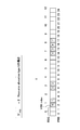
図3は、既存のPDCCHとFDM型PDCCHが配置されたサブフレーム構成を示す図である。サブフレームの先頭数OFDMシンボル(1~3OFDMシンボル)にはシステム帯域全体にわたり既存のPDCCHが配置され、既存のPDCCHが配置されたシンボル以降の無線リソースに、FDM型PDCCHが配置されている。1つのFDM型PDCCHの周波数領域の帯域幅は、無線リソースのスケジューリング単位の大きさ、例えば1リソースブロック(RB)である。
FIG. 3 is a diagram illustrating a subframe configuration in which an existing PDCCH and an FDM type PDCCH are arranged. An existing PDCCH is arranged over the entire system band in the first number OFDM symbol (1 to 3 OFDM symbols) of the subframe, and an FDM type PDCCH is arranged in radio resources after the symbol in which the existing PDCCH is arranged. The frequency domain bandwidth of one FDM type PDCCH is the size of a radio resource scheduling unit, for example, one resource block (RB).
このように、拡張PDCCHとしてFDM型PDCCHを、基地局装置eNBから移動端末装置UEへ下り制御信号を送信するための下りリンクでサポートすることにより、既存のPDSCH領域の所定の周波数領域を拡張PDCCH領域として使用することができる。拡張PDCCH領域は、既存のPDSCH領域に配置されるユーザ個別のDM-RS(DeModulation-Reference Signal)を用いて復調することができる。DM-RSは、UE個別の復調用参照信号として規定されており、UEに対して個別にビームフォーミングできるので、十分な受信品質が得られる。このため、セル端付近のUEであっても通信環境が良好であればアグリゲーションレベルを下げることができ、スループットの改善を図ることができる。
As described above, by supporting the FDM type PDCCH as the extended PDCCH in the downlink for transmitting the downlink control signal from the base station apparatus eNB to the mobile terminal apparatus UE, the predetermined frequency area of the existing PDSCH area is expanded PDCCH. Can be used as a region. The extended PDCCH region can be demodulated using a user-specific DM-RS (DeModulation-Reference Signal) arranged in the existing PDSCH region. The DM-RS is defined as a demodulation reference signal for each UE and can perform beam forming individually for the UE, so that sufficient reception quality can be obtained. For this reason, even if it is UE near cell edge, if a communication environment is favorable, an aggregation level can be lowered | hung and a throughput can be aimed at.
ここで、システム帯域に対する拡張PDCCH(FDM型PDCCH)の割り当て方法について図4を参照して説明する。なお、図4では、一例として25の物理リソースブロック(PRB:Physical Resource Block)で構成されるセル帯域幅に対して、拡張PDCCHとして8個(NVRB=8)の仮想リソースブロック(VRB:Virtual Resource Block)セットを設定する場合を示している。また、図4では、リソース配置タイプ0(Resource allocation type0)の場合を示している。もちろん、本発明はこれに限定されない。
Here, a method of assigning extended PDCCH (FDM type PDCCH) to the system band will be described with reference to FIG. In FIG. 4, as an example, 8 (N VRB = 8) virtual resource blocks (VRB: Virtual) as extended PDCCHs with respect to a cell bandwidth composed of 25 physical resource blocks (PRB). Resource Block) Set is shown. FIG. 4 shows a case of resource allocation type 0 (Resource allocation type 0). Of course, the present invention is not limited to this.
リソースブロック配置タイプは、3種類の異なるタイプ(Resource allocation type0,1,2)がある。リソースブロック配置タイプ0と1は周波数領域で非連続周波数配置をサポートし、タイプ2は連続周波数配置のみをサポートする。リソースブロック配置タイプ0は、周波数領域中の個々のリソースブロックでなく、隣接するリソースブロックのグループによって示すことにより、ビットマップのサイズを削減している。図4では、セル帯域幅が25リソースブロックであるため、リソースブロックグループ(RBG)のサイズが2となっている。この場合、8個のVRBセットは、2個単位でPRBに配置(RBG=1、3、7、8)される。
There are three different types of resource block allocation types ( Resource allocation type 0, 1, 2). Resource block allocation types 0 and 1 support discontinuous frequency allocation in the frequency domain, and type 2 supports only continuous frequency allocation. Resource block allocation type 0 reduces the size of the bitmap by indicating not by individual resource blocks in the frequency domain but by groups of adjacent resource blocks. In FIG. 4, since the cell bandwidth is 25 resource blocks, the size of the resource block group (RBG) is 2. In this case, eight VRB sets are arranged in the PRB in units of two (RBG = 1, 3, 7, 8).
基地局装置eNBは、移動端末装置UEに対して、拡張PDCCHとしてNVRB個のVRBセットを上位レイヤ信号で通知する。図4に示すように設定する場合には、移動端末装置UEに対して所定のRBG(ここでは、RBG=1、3、7、8)を通知する。また、VRBには、PRBインデックス(RBGインデックス)の小さい方から順番にVRBインデックスがナンバリングされる。
The base station apparatus eNB notifies the mobile terminal apparatus UE of N VRB VRB sets as an enhanced PDCCH using higher layer signals. In the case of setting as shown in FIG. 4, a predetermined RBG (here, RBG = 1, 3, 7, 8) is notified to the mobile terminal apparatus UE. Also, VRBs are numbered in order from the smaller PRB index (RBG index).
拡張PDCCHのリソースブロックは、前半スロット(1スロット目)と後半スロット(2スロット目)とに分けて下り制御信号を配置した構成とすることができる。また、拡張PDCCHのフォーマットとして、各ユーザの下り制御信号を複数のリソース要素グループ(REG)からなる制御チャネル要素(CCE)単位で割り当てる方法(with cross interleaving)と、各ユーザの下り制御信号をPRB単位で割り当てる方法(without cross interleaving)が考えられる。
The resource block of the extended PDCCH can be configured such that the downlink control signal is arranged in the first half slot (first slot) and the second half slot (second slot). Also, as a format of the extended PDCCH, a method (with cross interleaving) of assigning each user's downlink control signal in units of control channel elements (CCE) consisting of a plurality of resource element groups (REG), and a downlink control signal for each user is PRB. A method of allocation in units (without cross interleaving) is conceivable.
移動端末装置UEは、with cross interleavingの場合には、CCEインデックスで規定されたサーチスペース内でブラインド復号を行い、without cross interleavingの場合には、VRBインデックスで規定されたサーチスペース内でブラインド復号を行う。以下に各フォーマットにおけるブラインド復号について説明する。
In the case of with cross interleaving, the mobile terminal apparatus UE performs blind decoding in the search space specified by the CCE index, and in the case of without cross interleaving, performs blind decoding in the search space specified by the VRB index. Do. Hereinafter, blind decoding in each format will be described.
<with cross interleaving>
With cross interleavingにおいて、基地局装置eNBは、拡張PDCCHに対して、使用可能な無線リソース内の連続するREGから構成されるCCEを割り当てる。なお、1個のCCEは、9個のREGから構成される。また、1個のREGは、4個のリソースエレメントから構成される。例えば、基地局装置eNBは、各移動端末装置UEから通知された受信品質に基づいて、連続して割り当てるCCE数を示すアグリゲーションレベル(aggregation level Λ(=1,2,4,8))を決定する。そして、拡張PDCCHに対して、各移動端末装置UEのアグリゲーションレベルに応じたCCE数に対応するREGを設定する。
<With cross interleaving>
In With cross interleaving, the base station apparatus eNB allocates a CCE composed of consecutive REGs in usable radio resources to the extended PDCCH. One CCE is composed of nine REGs. One REG is composed of four resource elements. For example, the base station apparatus eNB determines an aggregation level (aggregation level Λ (= 1, 2, 4, 8)) indicating the number of CCEs to be continuously allocated based on the reception quality notified from each mobile terminal apparatus UE. To do. And REG corresponding to the number of CCEs according to the aggregation level of each mobile terminal apparatus UE is set with respect to extended PDCCH.
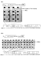
例えば、25個のPRBで構成されるセル帯域幅に対して、拡張PDCCHとして8個(NVRB=8)のVRBセットを、リソース配置タイプ0で配置する場合には、PRBの無線リソースに対して、図5Aに示すようにREGが配置される。
For example, for a cell bandwidth composed of 25 PRBs, when 8 VRB sets (N VRB = 8) as extended PDCCHs are allocated with resource allocation type 0, for PRB radio resources, Thus, the REG is arranged as shown in FIG. 5A.
1個のCCEを構成する9個のREGは、拡張PDCCHを構成するVRBの無線リソースに対して、周波数方向に連続して割り当てられる。図5Bに示すように、連続するVRBセットの周波数方向に割り当てられた9個のREGが1個のCCEを構成する。なお、VRBの無線リソースにおいて、CRSなどの参照信号として割り当てられるリソースエレメントに対しては、当該リソースエレメントを除いてREGの割り当てが行われる。また、基地局装置eNBは、各移動端末装置UEのアグリゲーションレベルに基づいて、各移動端末装置UEの拡張PDCCH信号に対して、連続するCCEの割り当てを行う。
Nine REGs constituting one CCE are continuously assigned in the frequency direction to the radio resources of the VRB constituting the extended PDCCH. As shown in FIG. 5B, nine REGs allocated in the frequency direction of successive VRB sets constitute one CCE. Note that, in a VRB radio resource, REG is assigned to a resource element assigned as a reference signal such as CRS except for the resource element. Further, the base station apparatus eNB assigns continuous CCEs to the extended PDCCH signal of each mobile terminal apparatus UE based on the aggregation level of each mobile terminal apparatus UE.
移動端末装置UEは、上位レイヤ信号によって設定される可能性のある複数の拡張PDCCHの候補をモニタする。これを、ブラインドデコーディングと称する。移動端末装置UEには、自装置あての拡張PDCCH信号が割り当てられているCCEおよび選択されているアグリゲーションレベルが通知されない。このため、自装置あての拡張PDCCH信号が割り当てられている可能性のあるすべてのCCEについて総当たりで拡張PDCCHの復号を行う。
The mobile terminal apparatus UE monitors a plurality of extended PDCCH candidates that may be set by higher layer signals. This is called blind decoding. The mobile terminal apparatus UE is not notified of the CCE to which the extended PDCCH signal addressed to the mobile terminal apparatus UE is allocated and the selected aggregation level. For this reason, the extended PDCCH is decoded in a round robin manner for all CCEs to which the extended PDCCH signal addressed to the own apparatus may be assigned.
また、基地局装置eNBは、移動端末装置UEによるブラインドデコーディングの試行回数を最小にするために、移動端末装置UEごとにサーチスペースを設定し、このサーチスペース内で、各移動端末装置UEあての拡張PDCCH信号用のCCEを割り当てることができる。この場合、移動端末装置UEは、対応するサーチスペース内で拡張PDCCHの復号を試みる。
Further, the base station apparatus eNB sets a search space for each mobile terminal apparatus UE in order to minimize the number of blind decoding attempts by the mobile terminal apparatus UE, and the mobile station apparatus UE addresses each mobile terminal apparatus UE within this search space. CCEs for extended PDCCH signals can be allocated. In this case, the mobile terminal apparatus UE attempts to decode the extended PDCCH within the corresponding search space.
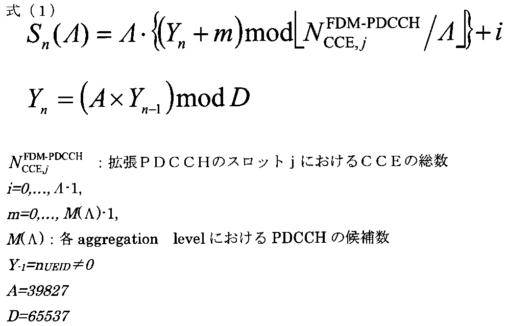
サーチスペース内でブラインドデコーディングを試行する場合、移動端末装置UEは、各アグリゲーションレベルに応じて、サーチスペースを以下の式(1)で求めることができる。なお、各アグリゲーションレベルΛ(=1,2,4,8)に対応したPDCCHの候補数は、それぞれ、6,6,2,2である。
When trying to perform blind decoding in the search space, the mobile terminal apparatus UE can obtain the search space by the following equation (1) according to each aggregation level. Note that the numbers of PDCCH candidates corresponding to each aggregation level Λ (= 1, 2, 4, 8) are 6, 6, 2, and 2, respectively.
<without cross interleaving>
Without cross interleavingにおいて、基地局装置eNBは、拡張PDCCHに対して、各移動端末装置UEあてのDCIをPRB単位で割り当てる。例えば、基地局装置eNBは、各移動端末装置UEから通知された受信品質に基づいて、連続して割り当てるVRB数を示すアグリゲーションレベルを決定する。そして、拡張PDCCHに対して、各移動端末装置UEのアグリゲーションレベルに応じた数のVRBを、移動端末装置UEあてのDCIの無線リソースとして割り当てる。
<Without cross interleaving>
In Without cross interleaving, the base station apparatus eNB allocates DCI addressed to each mobile terminal apparatus UE to the extended PDCCH in units of PRBs. For example, the base station apparatus eNB determines an aggregation level indicating the number of VRBs to be continuously allocated based on the reception quality notified from each mobile terminal apparatus UE. Then, the number of VRBs corresponding to the aggregation level of each mobile terminal apparatus UE is allocated to the extended PDCCH as DCI radio resources for the mobile terminal apparatus UE.
Without cross interleavingでは、拡張PDCCHに対して、無線リソースをPRB単位で各移動端末装置UEあてのDCIの無線リソースとして割り当てる。拡張PDCCHが配置される可能性のある無線リソースにはユーザ個別の下り参照信号であるDM-RSが配置される。このため、拡張PDCCHの復調をDM-RSを用いて行うことができる。この場合、PRB単位でのチャネル推定が可能であり、各移動端末装置UEに対して効果的にビームフォーミングを形成できる。
In Without cross interleaving, radio resources are allocated to the extended PDCCH as DCI radio resources for each mobile terminal apparatus UE in units of PRBs. A DM-RS, which is a downlink reference signal for each user, is arranged in a radio resource in which the extended PDCCH may be arranged. Therefore, it is possible to demodulate the extended PDCCH using DM-RS. In this case, channel estimation in units of PRB is possible, and beam forming can be effectively formed for each mobile terminal apparatus UE.
移動端末装置UEは、上位レイヤ信号によって設定される可能性のある複数の拡張PDCCHの候補をモニタする。移動端末装置UEには、自装置あてのDCIが割り当てられている拡張PDCCHのVRBおよび選択されているアグリゲーションレベルが通知されない。このため、自装置あてのDCIが割り当てられている可能性のあるすべての拡張PDCCH信号のVRBについて総当たりで拡張PDCCHの復号を行う。
The mobile terminal apparatus UE monitors a plurality of extended PDCCH candidates that may be set by higher layer signals. The mobile terminal apparatus UE is not notified of the VRB of the enhanced PDCCH to which the DCI addressed to itself is assigned and the selected aggregation level. For this reason, decoding of the extended PDCCH is performed for all VRBs of the extended PDCCH signals to which the DCI addressed to the own apparatus may be assigned.
また、基地局装置eNBは、移動端末装置UEによるブラインドデコーディングの試行回数を最小にするために、移動端末装置UEごとにサーチスペースを設定し、このサーチスペース内で、各移動端末装置UEあてのDCI用のVRBを割り当てることができる。この場合、移動端末装置UEは、対応するサーチスペース内でDCIの復号を行えばよい(図6参照)。
Further, the base station apparatus eNB sets a search space for each mobile terminal apparatus UE in order to minimize the number of blind decoding attempts by the mobile terminal apparatus UE, and the mobile station apparatus UE addresses each mobile terminal apparatus UE within this search space. VRBs for DCI can be allocated. In this case, the mobile terminal apparatus UE may perform DCI decoding within the corresponding search space (see FIG. 6).
サーチスペース内でブラインドデコーディングを試行する場合、移動端末装置UEは、各アグリゲーションレベル(VRB単位)に応じて、サーチスペースを以下の式(2)で求めることができる。なお、各アグリゲーションレベルΛ(=1,2,4,8)に対応したPDCCHの候補数は、それぞれ、6,6,2,2である。なお、ここでは、アグリゲーションレベルが6,6,2,2の場合について示しているが、もちろんアグリゲーションレベルおよびPDCCHの候補数は、これに限らない。
When trying to perform blind decoding in the search space, the mobile terminal apparatus UE can obtain the search space by the following equation (2) according to each aggregation level (in units of VRB). Note that the numbers of PDCCH candidates corresponding to each aggregation level Λ (= 1, 2, 4, 8) are 6, 6, 2, and 2, respectively. In addition, although it has shown about the case where an aggregation level is 6, 6, 2, 2, here, of course, the number of candidates of an aggregation level and PDCCH is not restricted to this.
25のPRBで構成されるセル帯域幅に対して、拡張PDCCHとして8個(NVRB=8)のVRBセットを、リソース配置タイプ0で配置する場合には、VRBには、PRBインデックス(RBGインデックス)の小さい方から順番にVRBインデックスがナンバリングされる(図6参照)。
When eight VRB sets (N VRB = 8) as extended PDCCH are arranged with a resource arrangement type 0 for a cell bandwidth composed of 25 PRBs, the PRB index (RBG index) is assigned to the VRB. VRB indexes are numbered in order from the smallest (see FIG. 6).
アグリゲーションレベル1では、VRB#0-#5に6つのサーチスペースが設定される。アグリゲーションレベル2では、VRB#0-#7に2VRB単位で4つのサーチスペースが設定される。アグリゲーションレベル4では、VRB#0-#7に4VRB単位で2つのサーチスペースが設定される。アグリゲーションレベル8では、VRB#0-#7に8VRB単位で1つのサーチスペースが設定される。なお、アグリゲーションレベル2、8では、VRB数の不足によってサーチスペースがオーバラップする。
In aggregation level 1, six search spaces are set in VRB # 0- # 5. At aggregation level 2, four search spaces are set in VRRB # 0 to # 7 in units of 2 VRB. At aggregation level 4, two search spaces are set in VRB # 0- # 7 in units of 4VRB. At aggregation level 8, one search space is set for VRB # 0 to # 7 in units of 8 VRB. Note that at aggregation levels 2 and 8, the search space overlaps due to a shortage of VRBs.
そして、移動端末装置UEにおいて、アグリゲーションレベルに応じてサーチスペースがブラインドデコーディングされ、VRBに割り当てられたDCIが取得される。このように、without cross interleavingでは、各ユーザのDCIがPRB単位で割り当てられ、VRBインデックスで規定されたサーチスペースでブラインドデコーディングされる。
Then, in the mobile terminal apparatus UE, the search space is blind-decoded according to the aggregation level, and the DCI assigned to the VRB is acquired. In this way, without cross interleaving, the DCI of each user is assigned in PRB units, and is blind-decoded in the search space defined by the VRB index.
このように、拡張PDCCH(FDM型PDCCH)を制御チャネル領域として利用することにより、下り制御チャネルの容量を確保することが可能となる。また、サーチスペースを限定することにより、移動端末装置UEにおけるブラインドデコーディングの試行回数を抑えることが可能となる。
Thus, by using the extended PDCCH (FDM type PDCCH) as the control channel region, it is possible to secure the capacity of the downlink control channel. In addition, by limiting the search space, it is possible to suppress the number of blind decoding attempts in the mobile terminal apparatus UE.
本発明の第2の側面は、PDCCHとFDM型PDCCHとで使用可能なアグリゲーションレベル、DCIフォーマットの種類を制限する。これにより、ブラインドデコーディング数を削減し、また環境に応じた特性の改善を図ることができる。
The second aspect of the present invention limits the types of aggregation levels and DCI formats that can be used in PDCCH and FDM type PDCCH. Thereby, it is possible to reduce the number of blind decoding and improve the characteristics according to the environment.
移動端末装置UEにおけるブラインドデコーディングの試行回数は、各アグリゲーションレベルΛ(=1,2,4,8)に対応したPDCCHの候補数(6,6,2,2)に基づく。例えば、アグリゲーションレベルΛ(=1,2,4,8)に対応したサーチスペース数が(6,6,2,2)の場合、移動端末装置UEは、既存のPDCCHを復号するために、16回(=6+6+2+2)のブラインドデコーディングを試行し、FDM型PDCCHを復号するために、16回のブラインドデコーディングを試行する。よって、PDCCHとFDM型PDCCHを併用する場合、PDCCHとFDM型PDCCHを併用しない場合と比較して、移動端末装置UEにおけるブラインドデコーディングの試行総数は増加する。
The number of blind decoding trials in the mobile terminal apparatus UE is based on the number of PDCCH candidates (6, 6, 2, 2) corresponding to each aggregation level Λ (= 1, 2, 4, 8). For example, when the number of search spaces corresponding to the aggregation level Λ (= 1, 2, 4, 8) is (6, 6, 2, 2), the mobile terminal apparatus UE uses 16 to decode the existing PDCCH. Attempts to perform blind decoding 16 times (= 6 + 6 + 2 + 2) and 16 times blind decoding in order to decode the FDM type PDCCH. Therefore, when PDCCH and FDM type PDCCH are used together, the total number of blind decoding trials in mobile terminal apparatus UE increases as compared with the case where PDCCH and FDM type PDCCH are not used together.
そこで、PDCCHとFDM型PDCCHとでアグリゲーションレベルΛが異なるよう、アグリゲーションレベルを制限する。例えば、PDCCHのアグリゲーションレベルを4または8に制限し、FDM型PDCCHのアグリゲーションレベルを1または2に制限する。これにより、移動端末装置UEにおけるブラインドデコーディング回数は、PDCCHに対して4回(=2+2)のブラインドデコーディングが試行され、FDM型PDCCHに対して12回(=6+6)のブラインドデコーディングが試行される。よって、PDCCHとFDM型PDCCHを併用する場合でも、移動端末装置UEにおけるブラインドデコーディングの試行総数を16回(=4+12)に抑えることができる。これは、PDCCHとFDM型PDCCHを併用しない場合の、移動端末装置UEにおけるブラインドデコーディングの試行総数と同数である。
Therefore, the aggregation level is limited so that the aggregation level Λ differs between the PDCCH and the FDM type PDCCH. For example, the aggregation level of PDCCH is limited to 4 or 8, and the aggregation level of FDM type PDCCH is limited to 1 or 2. Thereby, the blind decoding frequency in the mobile terminal apparatus UE is tried 4 times (= 2 + 2) for the PDCCH and 12 times (= 6 + 6) for the FDM type PDCCH. Is done. Therefore, even when the PDCCH and the FDM type PDCCH are used together, the total number of blind decoding trials in the mobile terminal apparatus UE can be suppressed to 16 times (= 4 + 12). This is the same as the total number of blind decoding trials in the mobile terminal apparatus UE when the PDCCH and the FDM type PDCCH are not used together.
なお、PDCCHおよびFDM型PDCCHに対するアグリゲーションレベルの制限は上記のケースに制限されない。例えば、ユーザ多重数が最大化するようにアグリゲーションレベルの制限を定めたり、セル端ユーザの特性改善が優先されるようにアグリゲーションレベルの制限を定めたりしてもよい。
In addition, the restriction | limiting of the aggregation level with respect to PDCCH and FDM type PDCCH is not restrict | limited to said case. For example, the aggregation level may be limited so that the number of multiplexed users is maximized, or the aggregation level may be limited so that improvement of the characteristics of the cell edge user is prioritized.
移動端末装置UEは、事前にPDCCHおよびFDM型PDCCHについてアグリゲーションレベルの制限が通知される。移動端末装置UEは、PDCCHおよびFDM型PDCCHのアグリゲーションレベルが制限されている場合、制限されたアグリゲーションレベルに応じたブラインドデコーディングの回数に制限されるのでブラインドデコーディング回数の総数を減らすことができる。
The mobile terminal apparatus UE is notified in advance of the restriction of the aggregation level for the PDCCH and the FDM type PDCCH. When the aggregation level of the PDCCH and the FDM type PDCCH is restricted, the mobile terminal apparatus UE is limited to the number of blind decodings according to the restricted aggregation level, so the total number of blind decodings can be reduced. .
また、PDCCHとFDM型PDCCHとでDCIフォーマットが異なるようにDCIフォーマット種別を制限する。例えば、PDCCHは、下りリンクスケジューリング割当用のDCI(例えば、DCIフォーマット1A,2など)の送信に制限し、FDM型PDCCHは、上りリンクグラント用のDCI(例えば、DCIフォーマット0,4など)の送信に制限する。なお、PDCCHおよびFDM型PDCCHにおけるDCIフォーマットの組合せはこれに限定されない。
Also, the DCI format type is limited so that the DCI format differs between the PDCCH and the FDM type PDCCH. For example, the PDCCH is limited to transmission of DCI for downlink scheduling allocation (for example, DCI format 1A, 2 etc.), and the FDM type PDCCH is for DCI for uplink grant (for example, DCI format 0, 4 etc.). Restrict to sending. The combination of DCI formats in PDCCH and FDM type PDCCH is not limited to this.
これにより、移動端末装置UEは、下りリンクスケジューリング割当用のDCIが時間的に先に復調されるので、FDM型PDCCHよりも時間的に早く受信されるPDCCHを復号した直後にPDSCHの復調を開始できる。
Accordingly, since the mobile terminal apparatus UE demodulates the DCI for downlink scheduling allocation in time, the mobile terminal apparatus UE starts demodulating the PDSCH immediately after decoding the PDCCH received earlier in time than the FDM type PDCCH. it can.
上記したアグリゲーションレベルの制限またはDCIフォーマットの制限は、上位レイヤシグナリングを用いて基地局装置eNBから移動端末装置UEに通知し、上記制限の設定をダイナミックに切り替えるように構成してもよい。これにより、システムの柔軟な運用が可能になる。
The above-described restriction on the aggregation level or the restriction on the DCI format may be notified from the base station apparatus eNB to the mobile terminal apparatus UE using higher layer signaling, and the setting of the restriction may be dynamically switched. As a result, the system can be operated flexibly.
本発明の第3の側面は、FDM型PDCCHが割り当てられたPRBの前半スロットと後半スロットとで、少なくとも一方のスロットに同一ビットサイズのDCIが複数配置されるように各スロットのDCI種別を制限する。これにより、移動端末装置UEにおけるブラインドデコーディングの試行回数が削減されるため、移動端末装置UEの負担を軽減できる。
The third aspect of the present invention limits the DCI type of each slot so that a plurality of DCIs of the same bit size are arranged in at least one slot in the first half slot and the second half slot of the PRB to which the FDM type PDCCH is allocated. To do. Thereby, since the frequency | count of trial of the blind decoding in the mobile terminal device UE is reduced, the burden on the mobile terminal device UE can be reduced.
例えば、LTE-A(Rel.10)で規定されたR-PDCCHは、前半スロットに下りリンクスケジューリング割当用DCI(例えば、DCIフォーマット1A,2Aなど)が配置され、後半スロットに上りリンクグラント用DCI(例えば、DCIフォーマット0,4など)が配置される。図7Aは、本発明者等が提案するFDM型PDCCHのリソースブロックに、R-PDCCHのDCI割当てをそのまま採用した場合のDCI配置を示す模式図である。
For example, in R-PDCCH defined in LTE-A (Rel. 10), DCI for downlink scheduling allocation (for example, DCI format 1A, 2A, etc.) is arranged in the first half slot, and DCI for uplink grant in the second half slot. (For example, DCI formats 0 and 4) are arranged. FIG. 7A is a schematic diagram showing a DCI arrangement in a case where R-PDCCH DCI assignment is directly adopted for the resource block of FDM type PDCCH proposed by the present inventors.
この場合、DCIフォーマット1Aと2Aとではビットサイズが異なるので別々にブラインドデコーディングが必要になる。また、DCIフォーマット0と4とはビットサイズが異なるので別々にブラインドデコーディングが必要になる。したがって、例えば、各アグリゲーションレベルΛ(=1,2,4,8)に対応したサーチスペース数が6,6,2,2であれば、移動端末装置UEにおいて、前半スロットに配置されたDCIフォーマット1Aに対して、(6+6+2+2=)16回のブラインドデコーディングが試行される。同様に、前半スロットに配置されたDCIフォーマット2A、後半スロットに配置されたDCIフォーマット0、後半スロットに配置されたDCIフォーマット4に対して、それぞれ16回のブラインドデコーディングが試行される。よって、移動端末装置UEにおけるブラインドデコーディングの試行総数は、16×4回(64回)となる。
In this case, since the bit sizes are different between the DCI formats 1A and 2A, blind decoding is required separately. Also, since the bit sizes of DCI formats 0 and 4 are different, blind decoding is required separately. Therefore, for example, if the number of search spaces corresponding to each aggregation level Λ (= 1, 2, 4, 8) is 6, 6, 2, 2, the DCI format arranged in the first half slot in the mobile terminal apparatus UE For 1A, (6 + 6 + 2 + 2 =) 16 blind decoding attempts are made. Similarly, 16 blind decodings are tried for DCI format 2A arranged in the first half slot, DCI format 0 arranged in the second half slot, and DCI format 4 arranged in the second half slot. Therefore, the total number of blind decoding trials in the mobile terminal apparatus UE is 16 × 4 times (64 times).
一方、図7Bは、前半スロットに同一ビットサイズのDCIが複数配置されるようにDCIフォーマットを制限した例である。図7Bに示すように、図7Aでは後半スロットに配置されていた上りリンクグラント用のDCIフォーマット0が、前半スロットに再配置されている。DCIフォーマット0は、前半スロットに配置されている下りリンクスケジューリング割当用のDCIフォーマット1Aと同じビットサイズである。
On the other hand, FIG. 7B is an example in which the DCI format is limited so that a plurality of DCIs having the same bit size are arranged in the first half slot. As shown in FIG. 7B, the DCI format 0 for uplink grant, which was placed in the latter half slot in FIG. 7A, is rearranged in the first half slot. The DCI format 0 has the same bit size as the DCI format 1A for downlink scheduling assignment allocated in the first half slot.
この場合、移動端末装置UEにおいて、前半スロットに配置されたDCIフォーマット1A,0は同一ビットサイズであるので、1度のブラインドデコーディング(最大16回)で同時に復号できる。前半スロットに配置された残りのDCIフォーマット2A、後半スロットに配置されたDCIフォーマット4に対して、それぞれ16回のブラインドデコーディングが試行される。よって、移動端末装置UEにおけるブラインドデコーディングの試行総数は、16×3回(48回)となる。したがって、移動端末装置UEにおけるブラインドデコーディングの試行回数が削減されるため、移動端末装置UEの負担を軽減できる。なお、DCIフォーマット1AとDCIフォーマット0とは、ブラインドデコーディングを16回試行した後で、先頭1ビットを処理することにより区別される。
In this case, since the DCI formats 1A and 0 arranged in the first half slot have the same bit size in the mobile terminal apparatus UE, they can be decoded simultaneously by one blind decoding (up to 16 times). For the remaining DCI format 2A arranged in the first half slot and the DCI format 4 arranged in the second half slot, 16 blind decodings are tried, respectively. Therefore, the total number of blind decoding trials in the mobile terminal apparatus UE is 16 × 3 times (48 times). Therefore, since the number of blind decoding trials in the mobile terminal apparatus UE is reduced, the burden on the mobile terminal apparatus UE can be reduced. DCI format 1A and DCI format 0 are distinguished by processing the first 1 bit after performing blind decoding 16 times.
なお、図7Aにおいて前半スロットに配置されていたDCIフォーマット1Aを、後半スロットに配置する構成としてもよい。この場合、後半スロットに同じビットサイズであるDCIフォーマット0,1Aが配置される。この場合にも、移動端末装置UEにおけるブラインドデコーディングの試行総数は、16×3回(48回)となる。なお、FDM型PDCCHのリソースブロックにおける、同じメッセージサイズのDCIフォーマットの組合せは上記例に限定されない。
Note that the DCI format 1A arranged in the first half slot in FIG. 7A may be arranged in the second half slot. In this case, DCI formats 0 and 1A having the same bit size are arranged in the latter half slot. Also in this case, the total number of blind decoding trials in the mobile terminal apparatus UE is 16 × 3 times (48 times). Note that the combination of DCI formats having the same message size in the resource block of the FDM type PDCCH is not limited to the above example.
本発明の第4の側面は、クロスキャリアスケジューリング(Cross-carrier scheduling)にFDM型PDCCHを適用した場合のサーチスペース構成を提供する。
4th aspect of this invention provides the search space structure at the time of applying FDM type PDCCH to cross-carrier scheduling (Cross-carrier scheduling).
LTE-A(Rel-10)では、LTE(Rel.8)までのシステム帯域に相当する基本周波数ブロックをコンポーネントキャリア(CC:Component Carrier)と呼称し、複数のCCを集めて広帯域化することが合意されている。一部のCCは他セルからの干渉が強いが、別のCCは干渉の影響が少ないといった通信環境が発生し得る。そこで、他セルからの干渉が強いCCで送られる共有データチャンネル(PDSCHなど)のためのDCIの割り当てを、干渉の影響の少ない別のCCから行う仕組みが検討されている。ここでは、PDSCHを送るCCのPDCCHを、そのCCとは別のCCから送ることをクロスキャリアスケジューリングと呼ぶ。
In LTE-A (Rel-10), a basic frequency block corresponding to a system band up to LTE (Rel. 8) is referred to as a component carrier (CC), and a plurality of CCs are collected to widen the band. It has been agreed. Some CCs are subject to strong interference from other cells, while other CCs may cause a communication environment in which the influence of interference is small. Therefore, a mechanism for performing DCI allocation for a shared data channel (PDSCH or the like) transmitted by a CC having strong interference from other cells from another CC having a small influence of interference has been studied. Here, sending a PDCCH of a CC that sends a PDSCH from a CC different from the CC is called cross-carrier scheduling.
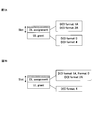
図8は、クロスキャリアスケジューリングが適用される場合の概念図である。図8に示す方法では、PDSCHを送るCC(セカンダリセル)のPDCCHを、そのCC(セカンダリセル)とは別のCC(プライマリセル)から送るクロスキャリアスケジューリングが適用されている。具体的には、CC#1のPDSCHまたはPUSCHを割り当てるためのDCI-1がCC#1のPDCCHに割り当てられ、CC#2のPDSCHまたはPUSCHを割り当てるためのDCI-2が異なるCC#1のPDCCHに割り当てられている。各DCIには、スケジューリング先のCCを指し示す3ビットのCIF(Carrier Indicator Field)が付加されている。移動端末装置UEは、復調したDCIに付加されているCIF値に基づいていずれのCCに割り当てたPDSCHであるかを判断できる。
FIG. 8 is a conceptual diagram when cross-carrier scheduling is applied. In the method shown in FIG. 8, cross-carrier scheduling is applied in which a PDCCH of a CC (secondary cell) that transmits PDSCH is transmitted from a CC (primary cell) different from the CC (secondary cell). Specifically, DCI-1 for assigning PDSCH or PUSCH of CC # 1 is assigned to PDCCH of CC # 1, and PDCCH of CC # 1 having different DCI-2 for assigning PDSCH or PUSCH of CC # 2 Assigned to. Each DCI is added with a 3-bit CIF (Carrier Indicator Field) indicating a CC to be scheduled. The mobile terminal apparatus UE can determine which CC is assigned to which CC based on the CIF value added to the demodulated DCI.
本発明は、クロスキャリアスケジューリングによって同一のCC(プライマリセル)に割り当てられたプライマリセルのPDSCH割り当て用のFDM型PDCCHと、セカンダリセルのPDSCH割り当て用のFDM型PDCCHとの2つのサーチスペースが連続するようにサーチスペースを構成する。図9にはプライマリセルとなるCC#1のサーチスペースとセカンダリセルとなるCC#2のサーチスペースとが連続構成となっている様子を示している。
In the present invention, two search spaces of an FDM type PDCCH for PDSCH allocation of a primary cell and an FDM type PDCCH for PDSCH allocation of a secondary cell that are allocated to the same CC (primary cell) by cross carrier scheduling are continuous. The search space is configured as follows. FIG. 9 shows a state in which the search space for CC # 1 serving as the primary cell and the search space for CC # 2 serving as the secondary cell have a continuous configuration.
このように、プライマリセルとセカンダリセルのサーチスペースが連続するサーチスペース構成により、プライマリセルとセカンダリセルのサーチスペースが重なるのを防止できる。これにより、異なるCC間のPDSCHを割り当てるDCIがブロッキングされる確率を低減することができる。
Thus, the search space configuration in which the search spaces of the primary cell and the secondary cell are continuous can prevent the search spaces of the primary cell and the secondary cell from overlapping. Thereby, the probability that DCI which allocates PDSCH between different CCs is blocked can be reduced.
FDM型PDCCHへのDCIの割り当て方法がwith cross interleavingの場合、サブフレームnにおけるサーチスペースの開始位置は以下の式(3)で求めることができる。なお、各アグリゲーションレベルΛ(=1,2,4,8)に対応したFDM型PDCCHの候補数は、それぞれ、6,6,2,2である。
When the DCI allocation method to the FDM type PDCCH is “with cross interleaving”, the start position of the search space in the subframe n can be obtained by the following equation (3). Note that the numbers of FDM PDCCH candidates corresponding to each aggregation level Λ (= 1, 2, 4, 8) are 6, 6, 2, and 2, respectively.
また、FDM型PDCCHへのDCIの割り当て方法がwithout cross interleavingの場合、PRB単位にDCIが割り当てられるので、サブフレームnにおけるサーチスペースの開始位置は以下の式(4)で求めることができる。
Also, when the DCI allocation method to the FDM type PDCCH is without cross interleaving, the DCI is allocated in units of PRBs, and therefore the search space start position in subframe n can be obtained by the following equation (4).
以下、図10を参照しながら、本発明の実施の形態に係る移動端末装置10および基地局装置20を有する無線通信システム1について説明する。移動端末装置10および基地局装置20は、LTE-Aをサポートしている。
Hereinafter, the radio communication system 1 having the mobile terminal apparatus 10 and the base station apparatus 20 according to the embodiment of the present invention will be described with reference to FIG. The mobile terminal apparatus 10 and the base station apparatus 20 support LTE-A.
図10に示すように、無線通信システム1は、基地局装置20と、この基地局装置20と通信する複数の移動端末装置10とを含んで構成されている。基地局装置20は、上位局装置30と接続され、この上位局装置30は、コアネットワーク40と接続される。また、基地局装置20は、有線接続または無線接続により相互に接続されている。各移動端末装置10は、セルC1、C2において基地局装置20と通信を行うことができる。なお、上位局装置30には、例えば、アクセスゲートウェイ装置、無線ネットワークコントローラ(RNC)、モビリティマネジメントエンティティ(MME)等が含まれるが、これに限定されない。
As shown in FIG. 10, the wireless communication system 1 includes a base station device 20 and a plurality of mobile terminal devices 10 that communicate with the base station device 20. The base station apparatus 20 is connected to the higher station apparatus 30, and the higher station apparatus 30 is connected to the core network 40. The base station devices 20 are connected to each other by wired connection or wireless connection. Each mobile terminal apparatus 10 can communicate with the base station apparatus 20 in the cells C1 and C2. The upper station device 30 includes, for example, an access gateway device, a radio network controller (RNC), a mobility management entity (MME), and the like, but is not limited thereto.
各移動端末装置10は、LTE端末およびLTE-A端末を含むが、以下においては、特段の断りがない限り移動端末装置として説明を進める。また、説明の便宜上、基地局装置20と無線通信するのは各移動端末装置10であるものとして説明するが、より一般的には移動端末装置も固定端末装置も含むユーザ装置でよい。
Each mobile terminal apparatus 10 includes an LTE terminal and an LTE-A terminal, but the following description will be given as a mobile terminal apparatus unless otherwise specified. Further, for convenience of explanation, it is assumed that each mobile terminal device 10 performs wireless communication with the base station device 20, but more generally user devices including both mobile terminal devices and fixed terminal devices may be used.
無線通信システム1においては、無線アクセス方式として、下りリンクについてはOFDMA(直交周波数分割多元接続)が適用され、上りリンクについてはSC-FDMA(シングルキャリア-周波数分割多元接続)が適用される。なお、上りリンクの無線アクセス方式はこれに限定されない。OFDMAは、周波数帯域を複数の狭い周波数帯域(サブキャリア)に分割し、各サブキャリアにデータをマッピングして通信を行うマルチキャリア伝送方式である。SC-FDMAは、システム帯域を端末ごとに1つまたは連続したリソースブロックからなる帯域に分割し、複数の端末が互いに異なる帯域を用いることで、端末間の干渉を低減するシングルキャリア伝送方式である。
In the radio communication system 1, OFDMA (Orthogonal Frequency Division Multiple Access) is applied to the downlink and SC-FDMA (Single Carrier Frequency Division Multiple Access) is applied to the uplink as the radio access scheme. The uplink radio access scheme is not limited to this. OFDMA is a multi-carrier transmission scheme that performs communication by dividing a frequency band into a plurality of narrow frequency bands (subcarriers) and mapping data to each subcarrier. SC-FDMA is a single carrier transmission scheme that reduces interference between terminals by dividing a system band into bands each consisting of one resource block or a continuous resource block for each terminal, and a plurality of terminals using different bands. .
ここで、LTE-Aで規定される通信チャネル構成について説明する。下りリンクの通信チャネルは、各移動端末装置10で共有されるPDSCHと、下りL1/L2制御チャネル(PDCCH、PCFICH、PHICH)と、拡張PDCCHとを有する。PDSCHにより、ユーザデータおよび上位制御信号が伝送される。ここでは、サブフレームの先頭から所定のOFDMシンボル数(1~3OFDMシンボル数)までの無線リソースに下り制御信号が多重され、所定のOFDMシンボル数より後の無線リソースに拡張PDCCH信号とPDSCH信号が周波数分割多重される。
Here, the communication channel configuration defined in LTE-A will be described. The downlink communication channel includes a PDSCH shared by each mobile terminal apparatus 10, a downlink L1 / L2 control channel (PDCCH, PCFICH, PHICH), and an extended PDCCH. User data and higher control signals are transmitted by PDSCH. Here, downlink control signals are multiplexed on radio resources from the beginning of a subframe to a predetermined number of OFDM symbols (1 to 3 OFDM symbols), and an extended PDCCH signal and a PDSCH signal are transmitted to radio resources after the predetermined number of OFDM symbols. Frequency division multiplexed.
拡張PDCCH(FDM型PDCCH)により、PDSCHおよびPUSCHのスケジューリング情報等が伝送される。拡張PDCCHは、PDSCHが割り当てられるリソース領域を用いてPDCCHの容量不足をサポートするために使用される。上位制御信号は、拡張PDCCHが設定されるPRB位置に関する情報(例えば、RBGの情報)、PDCCHおよび拡張PDCCHに対するアグリゲーションレベルの制限及びDCIフォーマット種別の制限、サーチスペースの開始位置を決定する制御式に用いるパラメータに関する情報などを含むことができる。
PDSCH and PUSCH scheduling information and the like are transmitted by the extended PDCCH (FDM type PDCCH). The extended PDCCH is used to support a lack of PDCCH capacity using a resource region to which the PDSCH is allocated. The upper control signal is a control expression that determines information related to the PRB position where the extended PDCCH is set (for example, RBG information), restrictions on the aggregation level for the PDCCH and the extended PDCCH, restrictions on the DCI format type, and a search space start position Information on parameters to be used can be included.
上りリンクの制御チャネルは、各移動端末装置10で共有されるPUSCHと、上りリンクの制御チャネルであるPUCCHとを有する。このPUSCHにより、ユーザデータが伝送される。PUCCHにより、下りリンクの無線品質情報(CQI:Channel Quality Indicator)、再送応答信号(ACK/NACK信号)等が伝送される。
The uplink control channel includes a PUSCH shared by each mobile terminal apparatus 10 and a PUCCH that is an uplink control channel. User data is transmitted by this PUSCH. Downlink radio quality information (CQI: Channel Quality Indicator), retransmission response signal (ACK / NACK signal), etc. are transmitted by PUCCH.
図11を参照しながら、本実施の形態に係る基地局装置20の全体構成について説明する。基地局装置20は、MIMO伝送のための複数の送受信アンテナ201と、アンプ部202と、送受信部(通知部)203と、ベースバンド信号処理部204と、呼処理部205と、伝送路インターフェース206とを備えている。
Referring to FIG. 11, the overall configuration of base station apparatus 20 according to the present embodiment will be described. The base station apparatus 20 includes a plurality of transmission / reception antennas 201 for MIMO transmission, an amplifier unit 202, a transmission / reception unit (notification unit) 203, a baseband signal processing unit 204, a call processing unit 205, and a transmission path interface 206. And.
基地局装置20から移動端末装置10へ送信されるユーザデータは、基地局装置20の上位局装置30から伝送路インターフェース206を介してベースバンド信号処理部204に入力される。ベースバンド信号処理部204は、PDCPレイヤの処理、ユーザデータの分割・結合、RLC(Radio Link Control)再送制御の送信処理などのRLCレイヤの送信処理、MAC(Medium Access Control)再送制御、例えば、HARQの送信処理、スケジューリング、伝送フォーマット選択、チャネル符号化、逆高速フーリエ変換(IFFT:Inverse Fast Fourier Transform)処理、プリコーディング処理を行う。
User data transmitted from the base station device 20 to the mobile terminal device 10 is input to the baseband signal processing unit 204 from the higher station device 30 of the base station device 20 via the transmission path interface 206. The baseband signal processing unit 204 performs PDCP layer processing, user data division / combination, RLC layer transmission processing such as RLC (Radio Link Control) retransmission control transmission processing, MAC (Medium Access Control) retransmission control, for example, HARQ transmission processing, scheduling, transmission format selection, channel coding, Inverse Fast Fourier Transform (IFFT) processing, and precoding processing are performed.
ベースバンド信号処理部204は、報知チャネルにより、移動端末装置10に対してセルにおける無線通信のための制御情報を通知する。セルにおける通信のための報知情報には、例えば、上りリンクまたは下りリンクにおけるシステム帯域幅、PRACHにおけるランダムアクセスプリアンブルの信号を生成するためのルート系列の識別情報(Root Sequence Index)等が含まれる。
The baseband signal processing unit 204 notifies the mobile terminal device 10 of control information for wireless communication in the cell through the broadcast channel. The broadcast information for communication in the cell includes, for example, system bandwidth in uplink or downlink, root sequence identification information (Root Sequence Index) for generating a random access preamble signal in PRACH, and the like.
各送受信部203は、ベースバンド信号処理部204からアンテナごとにプリコーディングして出力されたベースバンド信号を無線周波数帯に変換する。アンプ部202は、周波数変換された無線周波数信号を増幅して送受信アンテナ201により送信する。一方、上りリンクにより移動端末装置10から基地局装置20に送信されるデータについては、各送受信アンテナ201で受信された無線周波数信号がそれぞれアンプ部202で増幅され、各送受信部203で周波数変換されてベースバンド信号に変換され、ベースバンド信号処理部204に入力される。
Each transmitting / receiving unit 203 converts the baseband signal output by precoding from the baseband signal processing unit 204 for each antenna to a radio frequency band. The amplifier unit 202 amplifies the frequency-converted radio frequency signal and transmits the amplified signal using the transmission / reception antenna 201. On the other hand, for data transmitted from the mobile terminal apparatus 10 to the base station apparatus 20 via the uplink, radio frequency signals received by the respective transmitting / receiving antennas 201 are amplified by the amplifier sections 202 and frequency-converted by the respective transmitting / receiving sections 203. Is converted into a baseband signal and input to the baseband signal processing unit 204.
ベースバンド信号処理部204では、入力されたベースバンド信号に含まれるユーザデータに対して、FFT処理、IDFT処理、誤り訂正復号、MAC再送制御の受信処理、RLCレイヤ、PDCPレイヤの受信処理がなされ、伝送路インターフェース206を介して上位局装置30に転送される。呼処理部205は、通信チャネルの設定や解放等の呼処理や、基地局装置20の状態管理や、無線リソースの管理を行う。
The baseband signal processing unit 204 performs FFT processing, IDFT processing, error correction decoding, MAC retransmission control reception processing, RLC layer, and PDCP layer reception processing on user data included in the input baseband signal. The data is transferred to the higher station apparatus 30 via the transmission path interface 206. The call processing unit 205 performs call processing such as communication channel setting and release, state management of the base station apparatus 20, and radio resource management.
次に、図12を参照しながら、本実施の形態に係る移動端末装置の全体構成について説明する。LTE端末もLTE-A端末もハードウエアの主要部構成は同じであるので、区別せずに説明する。移動端末装置10は、MIMO伝送のための複数の送受信アンテナ101と、アンプ部102と、送受信部103と、ベースバンド信号処理部104と、アプリケーション部105とを備えている。
Next, the overall configuration of the mobile terminal apparatus according to the present embodiment will be described with reference to FIG. Since the LTE main unit and the LTE-A terminal have the same hardware configuration, they will be described without distinction. The mobile terminal apparatus 10 includes a plurality of transmission / reception antennas 101 for MIMO transmission, an amplifier unit 102, a transmission / reception unit 103, a baseband signal processing unit 104, and an application unit 105.
下りリンクのデータについては、複数の送受信アンテナ101で受信された無線周波数信号がそれぞれアンプ部102で増幅され、送受信部103で周波数変換されてベースバンド信号に変換される。このベースバンド信号は、ベースバンド信号処理部104でFFT処理や、誤り訂正復号、再送制御の受信処理等がなされる。この下りリンクのデータの内、下りリンクのユーザデータは、アプリケーション部105に転送される。アプリケーション部105は、物理レイヤやMACレイヤより上位のレイヤに関する処理等を行う。また、下りリンクのデータの内、報知情報もアプリケーション部105に転送される。
For downlink data, radio frequency signals received by a plurality of transmission / reception antennas 101 are respectively amplified by an amplifier unit 102, frequency-converted by a transmission / reception unit 103, and converted into a baseband signal. The baseband signal is subjected to FFT processing, error correction decoding, retransmission control reception processing, and the like by the baseband signal processing unit 104. Among the downlink data, downlink user data is transferred to the application unit 105. The application unit 105 performs processing related to layers higher than the physical layer and the MAC layer. Also, broadcast information in the downlink data is also transferred to the application unit 105.
一方、上りリンクのユーザデータは、アプリケーション部105からベースバンド信号処理部104に入力される。ベースバンド信号処理部104では、再送制御(H-ARQ (Hybrid ARQ))の送信処理や、チャネル符号化、プリコーディング、DFT処理、IFFT処理等が行われて各送受信部103に転送される。
On the other hand, uplink user data is input from the application unit 105 to the baseband signal processing unit 104. In the baseband signal processing unit 104, transmission processing of retransmission control (H-ARQ (Hybrid ARQ)), channel coding, precoding, DFT processing, IFFT processing, and the like are performed and transferred to each transmitting / receiving unit 103.
送受信部103は、ベースバンド信号処理部104から出力されたベースバンド信号を無線周波数帯に変換する。その後、アンプ部102は、周波数変換された無線周波数信号を増幅して送受信アンテナ101により送信する。
The transmission / reception unit 103 converts the baseband signal output from the baseband signal processing unit 104 into a radio frequency band. Thereafter, the amplifier unit 102 amplifies the frequency-converted radio frequency signal and transmits the amplified signal using the transmission / reception antenna 101.
図13は、本実施の形態に係る基地局装置20が有するベースバンド信号処理部204および一部の上位レイヤの機能ブロック図であり、主にベースバンド信号処理部204の送信処理の機能ブロックを示している。図13には、最大M個(CC#0~CC#M)のコンポーネントキャリア数に対応可能な基地局構成が例示されている。基地局装置20の配下となる移動端末装置10に対する送信データが上位局装置30から基地局装置20に対して転送される。
FIG. 13 is a functional block diagram of baseband signal processing section 204 and some higher layers included in base station apparatus 20 according to the present embodiment. Mainly, functional blocks of transmission processing of baseband signal processing section 204 are shown. Show. FIG. 13 exemplifies a base station configuration that can support a maximum of M (CC # 0 to CC # M) component carriers. Transmission data for the mobile terminal apparatus 10 under the control of the base station apparatus 20 is transferred from the upper station apparatus 30 to the base station apparatus 20.
制御情報生成部300は、上位レイヤ・シグナリング(例えばRRCシグナリング)する上位制御情報をユーザ単位で生成する。また、上位制御情報は、あらかじめ拡張PDCCH(FDM型PDCCH)をマッピングできるリソース配置(PRB位置)信号を含むことができる。また、サーチスペースの開始位置を決定する上記各制御式に用いるパラメータに関する情報、アグリゲーションレベルの制限またはDCIフォーマット種別の制限に関する情報等を生成する。
The control information generation unit 300 generates higher control information for higher layer signaling (for example, RRC signaling) for each user. Further, the upper control information can include a resource arrangement (PRB position) signal to which an extended PDCCH (FDM type PDCCH) can be mapped in advance. In addition, information on parameters used in the above control equations for determining the start position of the search space, information on aggregation level restrictions or DCI format type restrictions, and the like are generated.
データ生成部301は、上位局装置30から転送された送信データをユーザ別にユーザデータとして出力する。コンポーネントキャリア選択部302は、移動端末装置10との無線通信に使用されるコンポーネントキャリアをユーザごとに選択する。基地局装置20から移動端末装置10に対してRRCシグナリングによりコンポーネントキャリアの追加/削減を通知し、移動端末装置10から適用完了メッセージを受信する。
The data generation unit 301 outputs the transmission data transferred from the higher station apparatus 30 as user data for each user. The component carrier selection unit 302 selects a component carrier used for wireless communication with the mobile terminal device 10 for each user. The base station apparatus 20 notifies the mobile terminal apparatus 10 of addition / reduction of component carriers by RRC signaling, and receives an application completion message from the mobile terminal apparatus 10.
スケジューリング部310は、システム帯域全体の通信品質に応じて、配下の移動端末装置10に対するコンポーネントキャリアの割り当てを制御する。また、移動端末装置ごとに選択されたコンポーネントキャリアの中から特定のコンポーネントキャリア(PCC)が決められる。また、スケジューリング部310は、各コンポーネントキャリアCC#1-CC#Mにおけるリソースの割り当てを制御している。LTE端末ユーザとLTE-A端末ユーザとを区別してスケジューリングを行う。スケジューリング部310は、上位局装置30から送信データおよび再送指示が入力されるとともに、上りリンクの信号を測定した受信部からチャネル推定値やリソースブロックのCQIが入力される。
The scheduling unit 310 controls the allocation of component carriers to the subordinate mobile terminal devices 10 according to the communication quality of the entire system band. Also, a specific component carrier (PCC) is determined from the component carriers selected for each mobile terminal device. In addition, scheduling section 310 controls resource allocation in each component carrier CC # 1-CC # M. Scheduling is performed by distinguishing between LTE terminal users and LTE-A terminal users. Scheduling section 310 receives transmission data and a retransmission instruction from higher station apparatus 30 and receives a channel estimation value and a CQI of a resource block from a receiving section that measures an uplink signal.
また、スケジューリング部310は、入力された再送指示、チャネル推定値およびCQIを参照しながら、上下制御情報および上下共有チャネル信号のスケジューリングを行う。移動通信における伝搬路は、周波数選択性フェージングにより周波数ごとに変動が異なる。そこで、スケジューリング部310は、各移動端末装置10へのユーザデータについて、サブフレームごとに通信品質の良好なリソースブロック(マッピング位置)を指示する(適応周波数スケジューリングと呼ばれる)。適応周波数スケジューリングでは、各リソースブロックに対して伝搬路品質の良好な移動端末装置10を選択する。そのため、スケジューリング部310は、各移動端末装置10からフィードバックされるリソースブロックごとのCQIを用いてリソースブロック(マッピング位置)を指示する。
Further, the scheduling unit 310 performs scheduling of the up / down control information and the up / down shared channel signal while referring to the input retransmission instruction, channel estimation value, and CQI. The propagation path in mobile communication varies depending on the frequency due to frequency selective fading. Therefore, the scheduling unit 310 instructs a resource block (mapping position) with good communication quality for each subframe for user data to each mobile terminal apparatus 10 (referred to as adaptive frequency scheduling). In adaptive frequency scheduling, the mobile terminal apparatus 10 with good channel quality is selected for each resource block. Therefore, the scheduling unit 310 indicates a resource block (mapping position) using the CQI for each resource block fed back from each mobile terminal apparatus 10.
同様に、スケジューリング部310は、適応周波数スケジューリングによって拡張PDCCHで送信される制御情報等について、サブフレームごとに通信品質の良好なリソースブロック(マッピング位置)を指示する。このため、スケジューリング部310は、各移動端末装置10からフィードバックされるリソースブロックごとのCQIを用いてリソースブロック(マッピング位置)を指示する。
Similarly, the scheduling unit 310 instructs a resource block (mapping position) with good communication quality for each subframe with respect to control information and the like transmitted on the extended PDCCH by adaptive frequency scheduling. For this reason, the scheduling unit 310 indicates a resource block (mapping position) using the CQI for each resource block fed back from each mobile terminal apparatus 10.
また、スケジューリング部310は、移動端末装置10との間の伝搬路状況に応じてアグリゲーション数を制御する。PDCCHに関してはCCEアグリゲーション数、拡張PDCCHに関してはCCEアグリゲーション数(with cross interleavingの場合)またはVRBアグリゲーション数(without cross interleavingの場合)を制御する。なお、PDCCHと拡張PDCCHとでアグリゲーション数が制限される場合、制限されたアグリゲーション数の範囲内で制御する。例えば、PDCCHのアグリゲーション数が4,8に制限され、拡張PDCCHのアグリゲーション数が1,2に制限される。セル端ユーザに対してはCCEアグリゲーション数およびVRBアグリゲーション数を上げることになる。また、割り当てたリソースブロックで所定のブロック誤り率を満たすMCS(符号化率、変調方式)を決定する。スケジューリング部310が決定したMCS(符号化率、変調方式)を満足するパラメータがチャネル符号化部303、308、312、変調部304、309、313に設定される。
Also, the scheduling unit 310 controls the number of aggregations according to the propagation path status with the mobile terminal device 10. For the PDCCH, the number of CCE aggregation is controlled, and for the extended PDCCH, the number of CCE aggregation (with cross interleaving) or the number of VRB aggregations (without cross interleaving) is controlled. In addition, when the number of aggregation is restrict | limited by PDCCH and extended PDCCH, it controls within the range of the limited number of aggregation. For example, the number of PDCCH aggregations is limited to 4, 8, and the number of extended PDCCH aggregations is limited to 1, 2. For cell edge users, the number of CCE aggregation and the number of VRB aggregation will be increased. Also, an MCS (coding rate, modulation scheme) that satisfies a predetermined block error rate with the allocated resource block is determined. Parameters satisfying the MCS (coding rate, modulation scheme) determined by the scheduling unit 310 are set in the channel coding units 303, 308, 312 and the modulation units 304, 309, 313.
ベースバンド信号処理部204は、1コンポーネントキャリア内での最大ユーザ多重数Nに対応したチャネル符号化部303、変調部304、マッピング部305を備えている。チャネル符号化部303は、データ生成部301から出力されるユーザデータ(一部の上位制御信号を含む)で構成される下り共有データチャネル(PDSCH)を、ユーザごとにチャネル符号化する。変調部304は、チャネル符号化されたユーザデータをユーザごとに変調する。マッピング部305は、変調されたユーザデータを無線リソースにマッピングする。
The baseband signal processing unit 204 includes a channel encoding unit 303, a modulation unit 304, and a mapping unit 305 corresponding to the maximum user multiplexing number N within one component carrier. The channel coding unit 303 channel-codes the downlink shared data channel (PDSCH) composed of user data (including some higher control signals) output from the data generation unit 301 for each user. Modulation section 304 modulates channel-coded user data for each user. The mapping unit 305 maps the modulated user data to radio resources.
また、ベースバンド信号処理部204は、複数のDCIフォーマットの中から所定のDCIフォーマットを使用して制御情報を生成する生成部(下り制御情報生成部306および上り制御情報生成部311)を備えている。複数のDCIフォーマットには、上りリンクグラントを内容とするDCIフォーマット(例えば、DCIフォーマット0/4)、下りリンクスケジューリング割当を内容とするDCIフォーマット(例えば、DCIフォーマット1Aなど)が含まれている。スケジューリング部310は、下り制御情報生成部306および上り制御情報生成部311に対して、PDCCHと拡張PDCCHとで適用するDCIフォーマットを制限することができる。例えば、PDCCHには下りDCIフォーマット(1A,2等)だけを適用するように制限し、拡張PDCCHには上りDCIフォーマット(0,4等)だけを適用するように制限する。また、スケジューリング部310は、拡張PDCCHに関しては、時間領域の前半スロットまたは後半スロットには同一ビットサイズのDCIフォーマットが複数配置されるように制御する。
In addition, the baseband signal processing unit 204 includes generation units (downlink control information generation unit 306 and uplink control information generation unit 311) that generate control information using a predetermined DCI format from among a plurality of DCI formats. Yes. The plurality of DCI formats include a DCI format (for example, DCI format 0/4) including uplink grants and a DCI format (for example, DCI format 1A) including downlink scheduling allocation. Scheduling section 310 can limit the DCI format applied to PDCCH and enhanced PDCCH for downlink control information generation section 306 and uplink control information generation section 311. For example, the PDCCH is limited to apply only the downlink DCI format (1A, 2 etc.), and the extended PDCCH is limited to apply only the uplink DCI format (0, 4 etc.). Further, the scheduling unit 310 controls the extended PDCCH so that a plurality of DCI formats having the same bit size are arranged in the first half slot or the second half slot of the time domain.
下り制御情報生成部306は、下りリンクスケジューリング割当を内容とするDCIフォーマット(例えば、DCIフォーマット1Aなど)を用いて、PDSCHを制御するための下り共有データチャネル用制御情報を生成する。この際、当該下り共有データチャネル用制御情報は、ユーザごとに生成される。また、当該下り共有データチャネル用制御情報は、PDSCHが割り当てられた上りサービングセルを識別する識別フィールド(CIF)が含まれる。スケジューリング部310は、クロスキャリアスケジューリングが適用される場合、CIF値に基づいてサーチスペース開始位置を決定する。スケジューリング部310は、with cross interleavingの場合、式(3)で計算されるサーチスペース開始位置に基づいてサーチスペースを設定し、without cross interleavingの場合、式(4)で計算されるサーチスペース開始位置に基づいてサーチスペースを設定する。また、ベースバンド信号処理部204は、ユーザ共通の下り制御情報である下り共通制御チャネル用制御情報を生成する下り共通チャネル用制御情報生成部307を備えている。
The downlink control information generation unit 306 generates downlink shared data channel control information for controlling PDSCH using a DCI format (for example, DCI format 1A) including downlink scheduling allocation. At this time, the downlink shared data channel control information is generated for each user. Further, the downlink shared data channel control information includes an identification field (CIF) that identifies an uplink serving cell to which the PDSCH is assigned. Scheduling section 310 determines the search space start position based on the CIF value when cross-carrier scheduling is applied. In the case of with cross interleaving, the scheduling unit 310 sets a search space based on the search space start position calculated by Expression (3), and in the case of without cross interleaving, the search space start position calculated by Expression (4). Set search space based on. In addition, the baseband signal processing unit 204 includes a downlink common channel control information generation unit 307 that generates downlink common control channel control information that is downlink control information common to users.
上り制御情報生成部311は、上りリンクグラントを内容とするDCIフォーマット(例えば、DCIフォーマット0/4)を用いて、PUSCHを制御するための上り共有データチャネル用制御情報を生成する。当該上り共有データチャネル用制御情報は、ユーザごとに生成される。また、当該上り共有データチャネル用制御情報は、PUSCHが割り当てられた上りサービングセルを識別する識別フィールド(CIF)が含まれる。また、ベースバンド信号処理部204は、生成した上り共有データチャネル用制御情報をユーザごとにチャネル符号化するチャネル符号化部312と、チャネル符号化した上り共有データチャネル用制御情報をユーザごとに変調する変調部313とを備える。
The uplink control information generation unit 311 generates uplink shared data channel control information for controlling PUSCH using a DCI format (for example, DCI format 0/4) containing uplink grants. The uplink shared data channel control information is generated for each user. Further, the uplink shared data channel control information includes an identification field (CIF) for identifying an uplink serving cell to which a PUSCH is assigned. Further, the baseband signal processing unit 204 channel-encodes the generated uplink shared data channel control information for each user, and modulates the channel-encoded uplink shared data channel control information for each user. And a modulation unit 313.
セル固有参照信号生成部318は、セル固有参照信号(CRS:Cell-specific Reference Signal)を生成する。セル固有参照信号(CRS)は、上記PDCCH領域の無線リソースに多重されて送信される。また、ユーザ個別参照信号生成部320は、下り復調参照信号(DM-RS:Downlink Modulation-Reference Signal)を生成する。ユーザ固有の下り復調参照信号(DM-RS)は、上記PDSCH領域の無線リソースに多重されて送信される。
The cell-specific reference signal generation unit 318 generates a cell-specific reference signal (CRS). The cell-specific reference signal (CRS) is multiplexed with the radio resource in the PDCCH region and transmitted. Further, the user individual reference signal generation unit 320 generates a downlink demodulation reference signal (DM-RS: Downlink Modulation-Reference Signal). A user-specific downlink demodulation reference signal (DM-RS) is multiplexed and transmitted on the radio resource in the PDSCH region.
上記変調部309、313でユーザごとに変調された制御情報は制御チャネル多重部314で多重される。PDCCH用の下り制御情報は、サブフレームの先頭から1~3OFDMシンボルに多重され、インタリーブ部315でインタリーブされる。一方、拡張PDCCH(FRM型PDCCH)用の下り制御情報は、サブフレームの所定のシンボル数より後の無線リソースに周波数分割多重され、マッピング部319でリソースブロック(PRB)にマッピングされる。この場合、マッピング部319は、スケジューリング部310からの指示に基づいてマッピングする。なお、マッピング部319は、without cross interleavingだけでなく、with cross interleavingを適用してマッピングしてもよい。
The control information modulated for each user by the modulation units 309 and 313 is multiplexed by the control channel multiplexing unit 314. The downlink control information for PDCCH is multiplexed into 1 to 3 OFDM symbols from the top of the subframe, and interleaved by interleave section 315. On the other hand, downlink control information for enhanced PDCCH (FRM type PDCCH) is frequency-division multiplexed to radio resources after a predetermined number of symbols in a subframe, and mapped to resource blocks (PRB) by mapping section 319. In this case, the mapping unit 319 performs mapping based on an instruction from the scheduling unit 310. Note that the mapping unit 319 may perform mapping by applying not cross interleaving but also with cross interleaving.
プリコーディングウエイト乗算部321は、複数のアンテナごとに、サブキャリアにマッピングされた送信データおよびユーザ個別の復調用参照信号(DM-RS)の位相および/または振幅を制御(シフト)する。プリコーディングウエイト乗算部321により位相および/または振幅シフトされた送信データおよびユーザ個別の復調用参照信号(DM-RS)は、IFFT部316に出力される。
The precoding weight multiplication unit 321 controls (shifts) the phase and / or amplitude of the transmission data mapped to the subcarrier and the demodulation reference signal (DM-RS) for each user for each of the plurality of antennas. The transmission data and the user-specific demodulation reference signal (DM-RS) shifted in phase and / or amplitude by the precoding weight multiplication unit 321 are output to the IFFT unit 316.
IFFT部316には、インタリーブ部315およびマッピング部318から制御信号が入力され、マッピング部305からユーザデータが入力される。IFFT部316は、下りチャネル信号を逆高速フーリエ変換して周波数領域の信号から時系列の信号に変換する。サイクリックプレフィックス挿入部317は、下りチャネル信号の時系列信号にサイクリックプレフィックスを挿入する。なお、サイクリックプレフィックスは、マルチパス伝搬遅延の差を吸収するためのガードインターバルとして機能する。サイクリックプレフィックスが付加された送信データは、送受信部203に送出される。
The IFFT unit 316 receives control signals from the interleaving unit 315 and the mapping unit 318, and receives user data from the mapping unit 305. The IFFT unit 316 converts the downlink channel signal from a frequency domain signal to a time-series signal by performing inverse fast Fourier transform. The cyclic prefix insertion unit 317 inserts a cyclic prefix into the time-series signal of the downlink channel signal. The cyclic prefix functions as a guard interval for absorbing a difference in multipath propagation delay. The transmission data to which the cyclic prefix is added is sent to the transmission / reception unit 203.
図14は、ユーザ端末10が有するベースバンド信号処理部104の機能ブロック図であり、LTE-AをサポートするLTE-A端末の機能ブロックを示している。
FIG. 14 is a functional block diagram of the baseband signal processing unit 104 included in the user terminal 10, and shows functional blocks of the LTE-A terminal that supports LTE-A.
無線基地局装置20から受信データとして受信された下りリンク信号は、CP除去部401でCPが除去される。CPが除去された下りリンク信号は、FFT部402へ入力される。FFT部402は、下りリンク信号を高速フーリエ変換(FFT:Fast Fourier Transform)して時間領域の信号から周波数領域の信号に変換し、デマッピング部403へ入力する。デマッピング部403は、下りリンク信号をデマッピングし、下りリンク信号から複数の制御情報が多重された多重制御情報、ユーザデータ、上位制御信号を取り出す。なお、デマッピング部403によるデマッピング処理は、アプリケーション部105から入力される上位制御信号に基づいて行われる。デマッピング部403から出力された多重制御情報は、デインタリーブ部404でデインタリーブされる。なお、インタリーブされていない拡張PDCCH信号は、デインタリーブ部404を介さずに制御情報復調部405に入力される構成とすることができる。
CP is removed by the CP removal unit 401 from the downlink signal received from the radio base station apparatus 20 as reception data. The downlink signal from which the CP is removed is input to the FFT unit 402. The FFT unit 402 performs fast Fourier transform (FFT) on the downlink signal to convert it from a time domain signal to a frequency domain signal, and inputs it to the demapping unit 403. The demapping unit 403 demaps the downlink signal, and extracts multiplex control information, user data, and higher control signal in which a plurality of control information is multiplexed from the downlink signal. Note that the demapping process by the demapping unit 403 is performed based on a higher control signal input from the application unit 105. The multiplex control information output from the demapping unit 403 is deinterleaved by the deinterleaving unit 404. Note that an extended PDCCH signal that has not been interleaved may be input to control information demodulation section 405 without going through deinterleaving section 404.
また、ベースバンド信号処理部104は、制御情報を復調する制御情報復調部405、下り共有データを復調するデータ復調部406およびチャネル推定部407を備えている。制御情報復調部405は、多重制御情報から下り共通制御チャネル用制御情報を復調する共通制御チャネル用制御情報復調部405aと、多重制御情報から上り共有データチャネル用制御情報を復調する上り共有データチャネル用制御情報復調部405bと、多重制御情報から下り共有データチャネル用制御情報を復調する下り共有データチャネル用制御情報復調部405cとを備えている。データ復調部406は、ユーザデータおよび上位制御信号を復調する下り共有データ復調部406aと、下り共通チャネルデータを復調する下り共通チャネルデータ復調部406bとを備えている。
The baseband signal processing unit 104 includes a control information demodulation unit 405 that demodulates control information, a data demodulation unit 406 that demodulates downlink shared data, and a channel estimation unit 407. The control information demodulator 405 includes a common control channel control information demodulator 405a that demodulates downlink common control channel control information from the multiplex control information, and an uplink shared data channel that demodulates uplink shared data channel control information from the multiplex control information. And a downlink shared data channel control information demodulator 405c that demodulates downlink shared data channel control information from the multiplexed control information. The data demodulator 406 includes a downlink shared data demodulator 406a that demodulates user data and higher control signals, and a downlink common channel data demodulator 406b that demodulates downlink common channel data.
共通制御チャネル用制御情報復調部405aは、下りリンク制御チャネル(PDCCH)の共通サーチスペースのブラインドデコーディング処理、復調処理、チャネル復号処理などによりユーザ共通の制御情報である共通制御チャネル用制御情報を取り出す。共通制御チャネル用制御情報は、下りリンクのチャネル品質情報(CQI)を含んでおり、マッピング部415に入力され、基地局装置20への送信データの一部としてマッピングされる。
The common control channel control information demodulator 405a receives common control channel control information, which is common control information for users through blind decoding processing, demodulation processing, channel decoding processing, and the like of the common search space of the downlink control channel (PDCCH). Take out. The common control channel control information includes downlink channel quality information (CQI), is input to the mapping unit 415, and is mapped as part of transmission data to the base station apparatus 20.
上り共有データチャネル用制御情報復調部405bは、下りリンク制御チャネル(PDCCH)のユーザ個別サーチスペースのブラインドデコーディング処理、復調処理、チャネル復号処理などにより上り共有データチャネル用制御情報(例えば、UL Grant)を取り出す。復調された上り共有データチャネル用制御情報は、マッピング部415に入力されて、上り共有データチャネル(PUSCH)の制御に使用される。
The uplink shared data channel control information demodulator 405b performs uplink shared data channel control information (for example, UL Grant) through blind decoding processing, demodulation processing, channel decoding processing, and the like of the user-specific search space of the downlink control channel (PDCCH). ). The demodulated uplink shared data channel control information is input to the mapping unit 415 and used for uplink shared data channel (PUSCH) control.
下り共有データチャネル用制御情報復調部405cは、下りリンク制御チャネル(PDCCH)のユーザ個別サーチスペースのブラインドデコーディング処理、復調処理、チャネル復号処理などによりユーザ固有の下り共有データチャネル用制御情報(例えば、DL assignment)を取り出す。復調された下り共有データチャネル用制御情報は、下り共有データ復調部406へ入力されて、下り共有データチャネル(PDSCH)の制御に使用され、下り共有データ復調部406aに入力される。
The downlink shared data channel control information demodulating section 405c performs user-specific downlink shared data channel control information (for example, blind decoding processing, demodulation processing, channel decoding processing, etc.) for the user dedicated search space of the downlink control channel (PDCCH). , DL assignment). The demodulated downlink shared data channel control information is input to the downlink shared data demodulation unit 406, used for controlling the downlink shared data channel (PDSCH), and input to the downlink shared data demodulation unit 406a.
制御情報復調部405は、サブフレームの先頭シンボルからPCFICHを復調してPDCCHが配置される制御領域を特定し、特定された制御領域からPDCCHを復調する。また、制御情報復調部405は、制御領域の次シンボルからサブフレームの最終シンボルまでの無線リソース(データ領域)に周波数分割多重されている拡張PDCCHを復調する。
The control information demodulating unit 405 demodulates the PCFICH from the head symbol of the subframe to identify the control area where the PDCCH is arranged, and demodulates the PDCCH from the identified control area. Control information demodulation section 405 demodulates the extended PDCCH frequency-division multiplexed on the radio resource (data area) from the next symbol in the control area to the final symbol in the subframe.
クロスキャリアスケジューリングが適用される場合、制御情報復調部405は、with cross interleavingの場合には、式(3)でサーチスペース開始位置を計算し、計算したサーチスペース開始位置に基づいて特定されるサーチスペースをブラインドデコーディングする。また、without cross interleavingの場合には、式(4)でサーチスペース開始位置を計算し、計算されるサーチスペース開始位置に基づいてサーチスペースをブラインドデコーディングする。
When cross carrier scheduling is applied, the control information demodulating unit 405 calculates the search space start position using Equation (3) in the case of with cross interleaving, and searches specified based on the calculated search space start position. Blind decoding space. Further, in the case of without cross interleaving, the search space start position is calculated by Equation (4), and the search space is blind-decoded based on the calculated search space start position.
なお、”with cross interleaving”が適用された拡張PDCCHおよびPDCCHに対してCCE単位でブラインドデコーディングし、”without cross interleaving”が適用された拡張PDCCHおよびPDCCHに対して、VRB単位でブラインドデコーディングする。
In addition, blind decoding is performed in CCE units for extended PDCCH and PDCCH to which “with cross interleaving” is applied, and blind decoding is performed in VRB units to extended PDCCH and PDCCH to which “without cross interleaving” is applied. .
制御情報復調部405は、拡張PDCCHとPDCCHのアグリゲーション数の制限情報が通知されている場合、拡張PDCCHとPDCCHとでそれぞれ制限された各アグリゲーションレベルに応じたブラインドデコーディングを実行する。また、PDCCHには下りDCI(フォーマット1A,2等)が割り当てられ、拡張PDCCHには上りDCI(フォーマット0,4等)が割り当てられる場合は、PDCCHから下りDCIが復調され、拡張PDCCHから上りDCIが復調される。拡張PDCCHについて、前半スロットまたは後半スロットに同一ビットサイズのDCIフォーマットが複数配置されている場合は、同一ビットサイズのDCIフォーマットは1度のブラインドデコーディングによって同時に復調される。
The control information demodulator 405 performs blind decoding according to each aggregation level restricted by the extended PDCCH and the PDCCH when the restriction information on the number of aggregations of the extended PDCCH and the PDCCH is notified. Also, when downlink DCI ( format 1A, 2 etc.) is assigned to PDCCH and uplink DCI ( format 0, 4 etc.) is assigned to extended PDCCH, downlink DCI is demodulated from PDCCH and uplink DCI from extended PDCCH. Is demodulated. For the extended PDCCH, when a plurality of DCI formats having the same bit size are arranged in the first half slot or the second half slot, the DCI formats having the same bit size are demodulated simultaneously by one blind decoding.
下り共有データ復調部406aは、下り共有データチャネル用制御情報復調部405cから入力された下り共有データチャネル用制御情報に基づいて、ユーザデータや上位制御情報を取得する。上位制御情報に含まれる拡張PDCCHがマッピング可能なPRB位置(VRB位置)は、下り共有データチャネル用制御情報復調部405cに出力される。下り共通チャネルデータ復調部406bは、上り共有データチャネル用制御情報復調部405bから入力された上り共有データチャネル用制御情報に基づいて、下り共通チャネルデータを復調する。
The downlink shared data demodulator 406a acquires user data and higher control information based on the downlink shared data channel control information input from the downlink shared data channel control information demodulator 405c. The PRB position (VRB position) to which the extended PDCCH included in the higher control information can be mapped is output to the downlink shared data channel control information demodulation section 405c. The downlink common channel data demodulation unit 406b demodulates the downlink common channel data based on the uplink shared data channel control information input from the uplink shared data channel control information demodulation unit 405b.
チャネル推定部407は、ユーザ固有の参照信号(DM-RS)、またはセル固有の参照信号(CRS)を用いてチャネル推定する。通常のPDCCH、with cross interleavingの拡張PDCCHを復調する場合には、セル固有の参照信号を用いてチャネル推定する。一方、without cross interleavingの拡張PDCCHおよびユーザデータを復調する場合には、DM-RSおよびCRSを用いてチャネル推定する。推定されたチャネル変動を、共通制御チャネル用制御情報復調部405a、上り共有データチャネル用制御情報復調部405b、下り共有データチャネル用制御情報復調部405cおよび下り共有データ復調部406aに出力する。これらの復調部においては、推定されたチャネル変動および復調用の参照信号を用いて復調処理を行う。
The channel estimation unit 407 performs channel estimation using a user-specific reference signal (DM-RS) or a cell-specific reference signal (CRS). When demodulating a normal PDCCH and an extended PDCCH with cross interleaving, channel estimation is performed using a cell-specific reference signal. On the other hand, in the case of demodulating without cross interleaving extended PDCCH and user data, channel estimation is performed using DM-RS and CRS. The estimated channel fluctuation is output to the common control channel control information demodulator 405a, the uplink shared data channel control information demodulator 405b, the downlink shared data channel control information demodulator 405c, and the downlink shared data demodulator 406a. These demodulation units perform demodulation processing using the estimated channel fluctuation and demodulation reference signal.
ベースバンド信号処理部104は、送信処理系の機能ブロックとして、データ生成部411、チャネル符号化部412、変調部413、DFT部414、マッピング部415、IFFT部416、CP挿入部417を備えている。データ生成部411は、アプリケーション部105から入力されるビットデータから送信データを生成する。チャネル符号化部412は、送信データに対して誤り訂正等のチャネル符号化処理を施し、変調部413はチャネル符号化された送信データをQPSK等で変調する。
The baseband signal processing unit 104 includes a data generation unit 411, a channel encoding unit 412, a modulation unit 413, a DFT unit 414, a mapping unit 415, an IFFT unit 416, and a CP insertion unit 417 as functional blocks of a transmission processing system. Yes. The data generation unit 411 generates transmission data from the bit data input from the application unit 105. The channel coding unit 412 performs channel coding processing such as error correction on the transmission data, and the modulation unit 413 modulates the channel coded transmission data with QPSK or the like.
DFT部414は、変調された送信データを離散フーリエ変換する。マッピング部415は、DFT後のデータシンボルの各周波数成分を、基地局装置20に指示されたサブキャリア位置へマッピングする。IFFT部416は、システム帯域に相当する入力データを逆高速フーリエ変換して時系列データに変換し、CP挿入部417は時系列データに対してデータ区切りでサイクリックプレフィックスを挿入する。
The DFT unit 414 performs discrete Fourier transform on the modulated transmission data. Mapping section 415 maps each frequency component of the data symbol after DFT to a subcarrier position designated by base station apparatus 20. The IFFT unit 416 performs inverse fast Fourier transform on input data corresponding to the system band to convert it into time series data, and the CP insertion unit 417 inserts a cyclic prefix into the time series data at data delimiters.
なお、本発明は上記実施の形態に限定されず、さまざまに変更して実施可能である。上記実施の形態において、添付図面に図示されている大きさや形状などについては、これに限定されず、本発明の効果を発揮する範囲内で適宜変更が可能である。その他、本発明の目的の範囲を逸脱しない限りにおいて適宜変更して実施可能である。
It should be noted that the present invention is not limited to the above embodiment, and can be implemented with various modifications. In the above-described embodiment, the size, shape, and the like illustrated in the accompanying drawings are not limited thereto, and can be appropriately changed within a range in which the effect of the present invention is exhibited. In addition, various modifications can be made without departing from the scope of the object of the present invention.
本出願は、2011年5月2日出願の特願2011-103223に基づく。この内容は、全てここに含めておく。
This application is based on Japanese Patent Application No. 2011-103223 filed on May 2, 2011. All this content is included here.