WO2012144268A1 - Light duct and lighting device - Google Patents
Light duct and lighting device Download PDFInfo
- Publication number
- WO2012144268A1 WO2012144268A1 PCT/JP2012/054470 JP2012054470W WO2012144268A1 WO 2012144268 A1 WO2012144268 A1 WO 2012144268A1 JP 2012054470 W JP2012054470 W JP 2012054470W WO 2012144268 A1 WO2012144268 A1 WO 2012144268A1
- Authority
- WO
- WIPO (PCT)
- Prior art keywords
- film
- duct
- optical
- illuminance
- light
- Prior art date
Links
Images


Classifications
-
- F—MECHANICAL ENGINEERING; LIGHTING; HEATING; WEAPONS; BLASTING
- F21—LIGHTING
- F21S—NON-PORTABLE LIGHTING DEVICES; SYSTEMS THEREOF; VEHICLE LIGHTING DEVICES SPECIALLY ADAPTED FOR VEHICLE EXTERIORS
- F21S11/00—Non-electric lighting devices or systems using daylight
- F21S11/007—Non-electric lighting devices or systems using daylight characterised by the means for transmitting light into the interior of a building
-
- F—MECHANICAL ENGINEERING; LIGHTING; HEATING; WEAPONS; BLASTING
- F21—LIGHTING
- F21S—NON-PORTABLE LIGHTING DEVICES; SYSTEMS THEREOF; VEHICLE LIGHTING DEVICES SPECIALLY ADAPTED FOR VEHICLE EXTERIORS
- F21S19/00—Lighting devices or systems employing combinations of electric and non-electric light sources; Replacing or exchanging electric light sources with non-electric light sources or vice versa
- F21S19/005—Combining sunlight and electric light sources for indoor illumination
-
- F—MECHANICAL ENGINEERING; LIGHTING; HEATING; WEAPONS; BLASTING
- F21—LIGHTING
- F21V—FUNCTIONAL FEATURES OR DETAILS OF LIGHTING DEVICES OR SYSTEMS THEREOF; STRUCTURAL COMBINATIONS OF LIGHTING DEVICES WITH OTHER ARTICLES, NOT OTHERWISE PROVIDED FOR
- F21V7/00—Reflectors for light sources
- F21V7/0025—Combination of two or more reflectors for a single light source
- F21V7/0033—Combination of two or more reflectors for a single light source with successive reflections from one reflector to the next or following
-
- F—MECHANICAL ENGINEERING; LIGHTING; HEATING; WEAPONS; BLASTING
- F21—LIGHTING
- F21V—FUNCTIONAL FEATURES OR DETAILS OF LIGHTING DEVICES OR SYSTEMS THEREOF; STRUCTURAL COMBINATIONS OF LIGHTING DEVICES WITH OTHER ARTICLES, NOT OTHERWISE PROVIDED FOR
- F21V7/00—Reflectors for light sources
- F21V7/22—Reflectors for light sources characterised by materials, surface treatments or coatings, e.g. dichroic reflectors
-
- F—MECHANICAL ENGINEERING; LIGHTING; HEATING; WEAPONS; BLASTING
- F21—LIGHTING
- F21S—NON-PORTABLE LIGHTING DEVICES; SYSTEMS THEREOF; VEHICLE LIGHTING DEVICES SPECIALLY ADAPTED FOR VEHICLE EXTERIORS
- F21S2/00—Systems of lighting devices, not provided for in main groups F21S4/00 - F21S10/00 or F21S19/00, e.g. of modular construction
-
- F—MECHANICAL ENGINEERING; LIGHTING; HEATING; WEAPONS; BLASTING
- F21—LIGHTING
- F21V—FUNCTIONAL FEATURES OR DETAILS OF LIGHTING DEVICES OR SYSTEMS THEREOF; STRUCTURAL COMBINATIONS OF LIGHTING DEVICES WITH OTHER ARTICLES, NOT OTHERWISE PROVIDED FOR
- F21V23/00—Arrangement of electric circuit elements in or on lighting devices
- F21V23/04—Arrangement of electric circuit elements in or on lighting devices the elements being switches
- F21V23/0442—Arrangement of electric circuit elements in or on lighting devices the elements being switches activated by means of a sensor, e.g. motion or photodetectors
- F21V23/0464—Arrangement of electric circuit elements in or on lighting devices the elements being switches activated by means of a sensor, e.g. motion or photodetectors the sensor sensing the level of ambient illumination, e.g. dawn or dusk sensors
-
- F—MECHANICAL ENGINEERING; LIGHTING; HEATING; WEAPONS; BLASTING
- F21—LIGHTING
- F21Y—INDEXING SCHEME ASSOCIATED WITH SUBCLASSES F21K, F21L, F21S and F21V, RELATING TO THE FORM OR THE KIND OF THE LIGHT SOURCES OR OF THE COLOUR OF THE LIGHT EMITTED
- F21Y2103/00—Elongate light sources, e.g. fluorescent tubes
- F21Y2103/10—Elongate light sources, e.g. fluorescent tubes comprising a linear array of point-like light-generating elements
-
- F—MECHANICAL ENGINEERING; LIGHTING; HEATING; WEAPONS; BLASTING
- F21—LIGHTING
- F21Y—INDEXING SCHEME ASSOCIATED WITH SUBCLASSES F21K, F21L, F21S and F21V, RELATING TO THE FORM OR THE KIND OF THE LIGHT SOURCES OR OF THE COLOUR OF THE LIGHT EMITTED
- F21Y2113/00—Combination of light sources
-
- F—MECHANICAL ENGINEERING; LIGHTING; HEATING; WEAPONS; BLASTING
- F21—LIGHTING
- F21Y—INDEXING SCHEME ASSOCIATED WITH SUBCLASSES F21K, F21L, F21S and F21V, RELATING TO THE FORM OR THE KIND OF THE LIGHT SOURCES OR OF THE COLOUR OF THE LIGHT EMITTED
- F21Y2115/00—Light-generating elements of semiconductor light sources
- F21Y2115/10—Light-emitting diodes [LED]
Definitions
- the hemispherical reflectance of the semi-specular film 21 is 0.70 to 0.90.
- the hemispherical reflectance is the ratio of the total luminous flux of reflected light to the total luminous flux of incident light from all directions on the film surface.
- the light taken into the inside of the duct body 11, that is, into the cavity is normally incident on the surface in the cavity from all directions (all angles), so that the characteristics of the semi-specular film 21 used in the optical duct 10 are hemispherical. It is convenient to characterize by reflectance. This is because the hemispherical reflectance is not affected by the variation in reflectance with the incident angle, and the variation is already taken into account.
- the first semi-specular film 51 and the second semi-specular film 52 overlapped with each other are used as the optical layer. 14 is attached.
- both the first and second semi-specular films 51 and 52 have polarization.
- the lower limit of the hemispherical reflectance of the first and second semi-specular films 51 and 52 may be 0.20, 0.40, or 0.45.
- the upper limit of the hemispherical reflectance may be 0.55, 0.60, or 0.80.
- the hemispherical reflectivities of the semi-specular films 51 and 52 may be the same or different.
- the semi-specular films 51 and 52 are overlapped so that one film forms an angle ⁇ that is greater than 0 degree and less than 90 degrees with respect to the other film.
- a lighting device 200H shown in FIG. 24 is a modification of the lighting device 200F shown in FIG.
- the illumination device 200H differs from the illumination device 200F in that the wire 240 is omitted and the bar-type illumination 220 is attached only by the fixture 252. Also in this lighting device 200H, the inside of the fixture 252 to which the bar-type lighting 220 is attached is isolated from the space in the duct body 111 through which natural light passes. A reflective material is affixed to the inner wall separating the interior.
- Example 1-2 In the same manner as in Example 1-1, a duct body was produced and windows 1 to 3 were formed. The difference from Example 1-1 is that an additional diffusion plate (EX432) is attached to the diffusion sheet side of the multilayer optical film manufactured by 3M in the window 1. Therefore, the window 1 uses two diffusion plates. The optical layers in the windows 2 and 3 were the same as those in Example 1-1.
- EX432 additional diffusion plate
Landscapes
- Engineering & Computer Science (AREA)
- General Engineering & Computer Science (AREA)
- Architecture (AREA)
- Life Sciences & Earth Sciences (AREA)
- Sustainable Development (AREA)
- Non-Portable Lighting Devices Or Systems Thereof (AREA)
- Arrangement Of Elements, Cooling, Sealing, Or The Like Of Lighting Devices (AREA)
- Circuit Arrangement For Electric Light Sources In General (AREA)
Abstract
A light duct according to an embodiment of the present invention is provided with a duct main body, in which are formed at least one light collecting opening and at least one opening part, and a film having half-mirror surface properties attached to each of the at least one opening parts.
Description
本出願は、2011年4月22日に出願された日本国特許出願第2011-096358号の優先権を主張する。
This application claims the priority of Japanese Patent Application No. 2011-096358 filed on April 22, 2011.
本発明は、光ダクト及び照明装置に関する。
The present invention relates to an optical duct and a lighting device.
従来から、様々な光ダクトが知られている。例えば下記特許文献1には、光取り出し口の開口面積を、採光口から光ダクトの奥にゆくに従って大きくしたことを特徴とする光ダクト装置が記載されている。また、下記特許文献2には、所定の最大長と所定の発光特性とを有する光ガイド光抽出機構が記載されている。この抽出機構では、所定最大長の抽出機構の所定の末端から取り外されて短尺光ガイドに組み込まれた短尺セグメントにより、その短尺光ガイドがほぼ均一な表面光度を示す。
Conventionally, various optical ducts are known. For example, Patent Document 1 below discloses an optical duct device characterized in that the opening area of the light extraction port is increased from the daylighting port to the depth of the optical duct. Patent Document 2 below describes a light guide light extraction mechanism having a predetermined maximum length and a predetermined light emission characteristic. In this extraction mechanism, the short light guide exhibits a substantially uniform surface light intensity due to the short segments removed from the predetermined end of the predetermined maximum length extraction mechanism and incorporated into the short light guide.
上記特許文献1,2に記載されているような手法では、採光口から入射した光がダクト内を進むうちに吸収され又は漏洩してしまい、採光口に近い領域と採光口から離れた領域との間で照度の差が大きくなってしまう。そこで、ダクト内で光を効率良く伝達して、該ダクトから外部に放射される光の照度の均一性を高めることが要請されている。
In the methods as described in Patent Documents 1 and 2, the light incident from the lighting port is absorbed or leaked while traveling through the duct, and the region near the lighting port and the region away from the lighting port. The difference in illuminance between the two becomes large. Therefore, it is required to efficiently transmit light in the duct and improve the uniformity of the illuminance of the light emitted from the duct to the outside.
本発明の一態様に係る光ダクトは、少なくとも一つの採光口と、少なくとも一つの開口部とが形成されたダクト本体と、少なくとも一つの開口部のそれぞれに取り付けられた、半鏡面性を有するフィルムとを備える。
An optical duct according to an aspect of the present invention includes a duct body formed with at least one light outlet, at least one opening, and a film having semi-specularity attached to each of the at least one opening. With.
この場合、半鏡面性を有するフィルムが少なくとも一つの開口部のそれぞれに取り付けられるので、採光口から入射した光が、開口部において吸収されたり必要以上にダクト外に放射されたりすることなくダクト内を進む。これにより、採光口から離れている領域まで光を効率良く伝達することができ、その結果、光ダクトの全体において照度の均一性を高めることができる。
In this case, since the film having semi-specularity is attached to each of the at least one opening, the light incident from the lighting port is not absorbed in the opening or radiated outside the duct more than necessary. Continue on. Thereby, light can be efficiently transmitted to a region away from the lighting port, and as a result, uniformity of illuminance can be enhanced in the entire light duct.
別の形態に係る光ダクトでは、複数の開口部がダクト本体の長手方向に並んで形成されていてもよい。
In an optical duct according to another embodiment, a plurality of openings may be formed side by side in the longitudinal direction of the duct body.
さらに別の形態に係る光ダクトでは、フィルムの反射率が0.70~0.90であってもよい。
In a light duct according to still another embodiment, the reflectance of the film may be 0.70 to 0.90.
さらに別の態様に係る光ダクトでは、ダクト本体の内部に面するフィルムの片面がビーズコーティングされていてもよい。
In the optical duct according to still another aspect, one side of the film facing the inside of the duct body may be bead-coated.
さらに別の態様に係る光ダクトでは、少なくとも採光口に最も近い開口部に、それぞれが偏光性および半鏡面性を有する第1のフィルム及び第2のフィルムが取り付けられており、第2のフィルムが、第1のフィルムに対して0度より大きく且つ90度未満の角度をなすように、該第1のフィルムに重ねられていてもよい。
In the light duct according to another aspect, the first film and the second film each having polarization and semi-specularity are attached to at least the opening closest to the daylighting port, and the second film is The first film may be overlapped with the first film so as to form an angle larger than 0 degree and smaller than 90 degrees.
さらに別の態様に係る光ダクトでは、複数の開口部のうち連続する2以上の開口部に第1及び第2のフィルムが取り付けられており、連続する2以上の開口部のうち隣り合う任意の二つの開口部について、採光口に近い方の開口部における第1のフィルムと第2のフィルムとの成す角度が、他方の開口部における第1のフィルムと第2のフィルムとの成す角度以上であってもよい。
In the optical duct according to another aspect, the first and second films are attached to two or more continuous openings of the plurality of openings, and any adjacent two or more of the openings are adjacent to each other. For the two openings, the angle formed by the first film and the second film in the opening closer to the daylight opening is equal to or greater than the angle formed by the first film and the second film in the other opening. There may be.
さらに別の態様に係る光ダクトでは、第1及び第2のフィルムの反射率がそれぞれ0.20~0.80であってもよい。
In the optical duct according to still another aspect, the reflectivities of the first and second films may be 0.20 to 0.80, respectively.
さらに別の形態に係る光ダクトでは、第1及び第2のフィルムの一方が他方に対して回転可能に設けられており、これにより角度が調整可能であってもよい。
In the optical duct according to still another embodiment, one of the first and second films is provided so as to be rotatable with respect to the other, whereby the angle may be adjustable.
さらに別の形態に係る光ダクトでは、複数の開口部の形状及び寸法が略同一であってもよい。
In the optical duct according to still another embodiment, the shapes and dimensions of the plurality of openings may be substantially the same.
本発明の一形態に係る照明装置は、上記の光ダクトと、光ダクトに設けられた光源とを備える。
An illumination device according to an aspect of the present invention includes the above-described optical duct and a light source provided in the optical duct.
別の形態に係る照明装置では、光源がダクト本体の内部に設けられていてもよい。
In a lighting device according to another embodiment, a light source may be provided inside the duct body.
さらに別の形態に係る照明装置では、光源が、開口部が形成されているダクト本体の面の下方に設けられていてもよい。
In a lighting device according to yet another embodiment, the light source may be provided below the surface of the duct body in which the opening is formed.
さらに別の形態に係る照明装置は、照度を測定する照度センサと、照度センサにより測定された照度が第1の閾値未満である場合に光源を点灯させ、該照度が第2の閾値以上である場合に光源を消灯させる回路であって、該第2の閾値が該第1の閾値よりも大きい、該回路とを更に備えてもよい。
An illuminating device according to another aspect of the present invention includes an illuminance sensor that measures illuminance, and turns on the light source when the illuminance measured by the illuminance sensor is less than a first threshold, and the illuminance is greater than or equal to the second threshold. In some cases, the circuit may further comprise a circuit for turning off the light source, wherein the second threshold value is larger than the first threshold value.
さらに別の形態に係る照明装置は、照度を測定する照度センサと、照度センサにより測定された照度が第1の閾値未満である場合に光源の輝度を上げ、該測定された照度が第2の閾値以上である場合に光源の輝度を下げる回路であって、該第2の閾値が該第1の閾値よりも大きい、該回路とを更に備える。
An illuminating device according to another aspect includes an illuminance sensor that measures illuminance, and when the illuminance measured by the illuminance sensor is less than a first threshold, the luminance of the light source is increased, and the measured illuminance is the second The circuit further includes a circuit for lowering the luminance of the light source when the threshold is equal to or higher than the threshold, wherein the second threshold is larger than the first threshold.
本発明の一側面によれば、ダクト内で光を効率良く伝達して、該ダクトから外部に放射される光の照度の均一性を高めることができる。
According to one aspect of the present invention, it is possible to efficiently transmit light in a duct and improve the uniformity of the illuminance of light emitted from the duct to the outside.
以下、添付図面を参照しながら本発明の実施形態を詳細に説明する。なお、図面の説明において同一又は同等の要素には同一の符号を付し、重複する説明を省略する。
Hereinafter, embodiments of the present invention will be described in detail with reference to the accompanying drawings. In the description of the drawings, the same or equivalent elements are denoted by the same reference numerals, and redundant description is omitted.
(第1実施形態)
まず、図1~3を用いて、第1実施形態に係る光ダクト10の構成を説明する。光ダクト10は、取り入れた光を目的の位置まで搬送してダクト外の空間に放射することで、その光を照明や補助照明として用いるための管状部材である。光ダクト10は、例えば太陽光を室内の照明に利用するために採用される。もっとも、光ダクト10により搬送される光は自然光(太陽光)に限定されず、人工光でもよい。 (First embodiment)
First, the configuration of theoptical duct 10 according to the first embodiment will be described with reference to FIGS. The light duct 10 is a tubular member for transporting taken light to a target position and radiating it to a space outside the duct, thereby using the light as illumination or auxiliary illumination. The optical duct 10 is employed, for example, to use sunlight for indoor lighting. But the light conveyed by the optical duct 10 is not limited to natural light (sunlight), and may be artificial light.
まず、図1~3を用いて、第1実施形態に係る光ダクト10の構成を説明する。光ダクト10は、取り入れた光を目的の位置まで搬送してダクト外の空間に放射することで、その光を照明や補助照明として用いるための管状部材である。光ダクト10は、例えば太陽光を室内の照明に利用するために採用される。もっとも、光ダクト10により搬送される光は自然光(太陽光)に限定されず、人工光でもよい。 (First embodiment)
First, the configuration of the
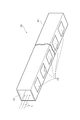
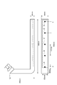
光ダクト10の一例を図1に示す。図1における光ダクト10の本体(以下では「ダクト本体」という)11の断面形状は矩形である。このダクト本体11の一端には、光Lを取り入れるための採光口12が形成されている。ダクト本体11の内壁全面には、光をほぼ全反射する反射材がラミネート加工などにより貼られている。図1,2に示すように、ダクト本体11の長手方向に延びる一面には、光をダクト本体11の外の空間に放射するための複数の窓13が、該長手方向に沿って所定の間隔をおいて形成されている。
An example of the optical duct 10 is shown in FIG. The cross-sectional shape of the main body (hereinafter referred to as “duct main body”) 11 of the optical duct 10 in FIG. 1 is rectangular. At one end of the duct body 11, a lighting port 12 for taking in the light L is formed. On the entire inner wall of the duct body 11, a reflective material that almost totally reflects light is attached by laminating or the like. As shown in FIGS. 1 and 2, a plurality of windows 13 for radiating light to a space outside the duct body 11 are provided at a predetermined interval along the longitudinal direction on one surface extending in the longitudinal direction of the duct body 11. Is formed.
窓13は、ダクト本体11に形成された開口部14と、その開口部14を覆う構成要素(光学層)とから成る。各開口部14の形状及び寸法は同一又は略同一である。光学層の構成は図3に示すようにいくつか考えられる。
The window 13 includes an opening 14 formed in the duct body 11 and a component (optical layer) that covers the opening 14. The shape and size of each opening 14 are the same or substantially the same. Several configurations of the optical layer are conceivable as shown in FIG.
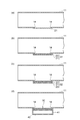
図3(a)の例では、半鏡面性を有するフィルム(以下では「半鏡面性フィルム」という)21が光学層として開口部14に取り付けられている。半鏡面性を有するフィルムとは、吸収などによる光の損失をほとんど生ずることなく、入射光の一部を反射し残りの光を透過するという特性を持つフィルムのことである。したがって、半鏡面性フィルムでは、「(反射光)+(透過光)≒(入射光)」という関係が成り立つ。
In the example of FIG. 3A, a film having semi-specularity (hereinafter referred to as “semi-specular film”) 21 is attached to the opening 14 as an optical layer. A film having a semi-specularity is a film having a characteristic of reflecting a part of incident light and transmitting the remaining light with little loss of light due to absorption or the like. Therefore, in the semi-specular film, the relationship “(reflected light) + (transmitted light) ≈ (incident light)” is established.
本実施形態では、半鏡面性フィルム21の半球反射率は0.70~0.90である。ここで、半球反射率とは、フィルム表面への全方向からの入射光の全光束に対する、反射光の全光束の割合である。ダクト本体11の内部、すなわち空洞内に取り込まれた光は通常、その空洞内の表面上に全方向(全角度)から入射するので、光ダクト10で用いられる半鏡面性フィルム21の特性を半球反射率で特徴付けることは都合がよい。なぜなら、半球反射率は、入射角に伴う反射率のばらつきに左右されず、且つそのばらつきを既に考慮しているからである。
In this embodiment, the hemispherical reflectance of the semi-specular film 21 is 0.70 to 0.90. Here, the hemispherical reflectance is the ratio of the total luminous flux of reflected light to the total luminous flux of incident light from all directions on the film surface. The light taken into the inside of the duct body 11, that is, into the cavity is normally incident on the surface in the cavity from all directions (all angles), so that the characteristics of the semi-specular film 21 used in the optical duct 10 are hemispherical. It is convenient to characterize by reflectance. This is because the hemispherical reflectance is not affected by the variation in reflectance with the incident angle, and the variation is already taken into account.
この半鏡面性フィルム21は、例えば、所望の屈折率関係及び所望の反射率特性を生成するように適切な条件下で配向された、共押出ポリマーミクロ層(多層構造)を有する。半鏡面性フィルム21の作製においては、所望の半球反射率が得られるように、ミクロ層の数や層厚さ特性、屈折率等が適切に選択される。この点から、半鏡面性フィルム21は、半球反射率及び半球透過率が制御されたフィルムであるともいえる。ただし、半球反射率と半球透過率との和は、ほぼ1である。ここで、半球透過率とは、フィルム表面への全方向からの入射光の全光束に対する、透過光の全光束の割合である。半鏡面性フィルム21は、偏光フィルムであってもよいし、偏光フィルムでなくてもよい。また、半鏡面性フィルム21は非対称反射特性を有していてもよいし、対称性を有する多層構造を有していてもよい。
This semi-specular film 21 has, for example, a coextruded polymer microlayer (multilayer structure) oriented under appropriate conditions to produce the desired refractive index relationship and the desired reflectivity characteristics. In the production of the semi-specular film 21, the number of micro layers, the layer thickness characteristics, the refractive index, and the like are appropriately selected so as to obtain a desired hemispherical reflectance. From this point, it can be said that the semi-specular film 21 is a film in which the hemispherical reflectance and the hemispherical transmittance are controlled. However, the sum of the hemispherical reflectance and the hemispherical transmittance is approximately 1. Here, the hemispherical transmittance is the ratio of the total luminous flux of transmitted light to the total luminous flux of incident light from all directions on the film surface. The semi-specular film 21 may be a polarizing film or may not be a polarizing film. The semi-specular film 21 may have asymmetric reflection characteristics or may have a multilayer structure having symmetry.
このような半鏡面性フィルム21の構造や特性については、特表2010-528430号公報にも記載されている。
The structure and characteristics of such a semi-specular film 21 are also described in JP-T-2010-528430.
図3(b)の例では、片面にビーズコーティング22が施された、偏光性を有する半鏡面性フィルム21(多層光学フィルム31)が光学層として開口部14に取り付けられている。この多層光学フィルム31は、ビーズコーティング22がダクト本体11の内部に面するように開口部14に取り付けられる。ビーズコーティング22は、公知の透明樹脂製の微細なビーズ(例えば、ポリメチルメタクリレート(PMMA)ビーズ)、またはガラスビーズ等の微粒子を多数含むポリマー結合剤により形成される。ビーズコーティング22は、ダクト本体11内の空間に反射される光を拡散させるために用いられる。
In the example of FIG. 3B, a semi-specular film 21 (multilayer optical film 31) having a polarizing property and having a bead coating 22 on one surface is attached to the opening 14 as an optical layer. The multilayer optical film 31 is attached to the opening 14 so that the bead coating 22 faces the inside of the duct body 11. The bead coating 22 is formed of a known binder resin-made fine beads (for example, polymethyl methacrylate (PMMA) beads) or a polymer binder containing a large number of fine particles such as glass beads. The bead coating 22 is used for diffusing light reflected in the space in the duct body 11.
図3(c)の例では、片面にビーズコーティング22が施され、他方の面に透明樹脂製の拡散シート23が貼り付けられた半鏡面性フィルム21(多層光学フィルム32)が光学層として開口部14に取り付けられている。この多層光学フィルム32も、ビーズコーティング22がダクト本体11の内部に面するように開口部14に取り付けられる。拡散シート23に用いる透明樹脂としては、例えばポリカーボネートが挙げられるが、拡散シート23の材料はこれに限定されない。
In the example of FIG. 3C, a semi-specular film 21 (multilayer optical film 32) having a bead coating 22 on one side and a transparent resin diffusion sheet 23 attached to the other side is opened as an optical layer. It is attached to the part 14. This multilayer optical film 32 is also attached to the opening 14 so that the bead coating 22 faces the inside of the duct body 11. Examples of the transparent resin used for the diffusion sheet 23 include polycarbonate, but the material of the diffusion sheet 23 is not limited to this.
図3(d)の例では、光学層は多層光学フィルム32と透明樹脂製の拡散板42とを備える。具体的には、断面形状が多層光学フィルム32と同じであり内側に反射材がラミネート加工された管状部材41の一端が、その多層光学フィルム32を覆うようにダクト本体11に取り付けられる。そして、その管状部材41の他端に拡散板42が取り付けられる。したがって、多層光学フィルム32と拡散板42との間には空間が形成される。拡散板42に用いる透明樹脂としては、例えばアクリルが挙げられるが、拡散板42の材料はこれに限定されない。また、拡散板42は彩色されていてもよいし、半透明であってもよい。
In the example of FIG. 3D, the optical layer includes a multilayer optical film 32 and a diffusion plate 42 made of a transparent resin. Specifically, one end of a tubular member 41 having the same cross-sectional shape as the multilayer optical film 32 and laminated with a reflective material on the inside is attached to the duct body 11 so as to cover the multilayer optical film 32. A diffusion plate 42 is attached to the other end of the tubular member 41. Accordingly, a space is formed between the multilayer optical film 32 and the diffusion plate 42. Examples of the transparent resin used for the diffusion plate 42 include acrylic, but the material of the diffusion plate 42 is not limited to this. The diffusion plate 42 may be colored or translucent.
以上説明したように、本実施形態によれば、半鏡面性フィルム21が各開口部14に取り付けられるので、採光口12から入射した光が、開口部14において吸収されたり必要以上にダクト本体11外に放射されたりすることなくダクト本体11内を進む。これにより、採光口12から離れている領域まで光を効率良く伝達することができ、その結果、光ダクト10の全体において照度の均一性を高めることができる。
As described above, according to the present embodiment, since the semi-specular film 21 is attached to each opening 14, the light incident from the lighting port 12 is absorbed in the opening 14 or more than necessary. It proceeds through the duct body 11 without being radiated to the outside. Thereby, light can be efficiently transmitted to a region away from the lighting port 12, and as a result, the illuminance uniformity can be enhanced in the entire optical duct 10.
また、本実施形態によれば、各開口部14の形状及び寸法を同じにできるので、光ダクト10を容易に設計および製造することができる。更に、各開口部14に同じ半鏡面性フィルム21を取り付ければよいので、光ダクト10の製造が容易である。
Moreover, according to this embodiment, since the shape and dimension of each opening part 14 can be made the same, the optical duct 10 can be designed and manufactured easily. Furthermore, since the same semi-specular film 21 should just be attached to each opening part 14, manufacture of the optical duct 10 is easy.
(第2実施形態)
次に、第2実施形態に係る光ダクト10について説明する。第2実施形態が第1実施形態と異なる点は、窓13の一部を成す光学層の構成である。本実施形態における他の構成は第1実施形態と同じなのでその説明を省略し、以下では、図4,5を用いて光学層の構成について説明する。 (Second Embodiment)
Next, theoptical duct 10 according to the second embodiment will be described. The second embodiment differs from the first embodiment in the configuration of the optical layer that forms part of the window 13. Since other configurations in the present embodiment are the same as those in the first embodiment, the description thereof will be omitted, and the configuration of the optical layer will be described below with reference to FIGS.
次に、第2実施形態に係る光ダクト10について説明する。第2実施形態が第1実施形態と異なる点は、窓13の一部を成す光学層の構成である。本実施形態における他の構成は第1実施形態と同じなのでその説明を省略し、以下では、図4,5を用いて光学層の構成について説明する。 (Second Embodiment)
Next, the
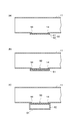
図4(a)の例では、互いに重ね合わされた第1の半鏡面性フィルム51及び第2の半鏡面性フィルム52(以下では「2枚重ねのフィルム50」ともいう)が光学層として開口部14に取り付けられている。本実施形態では、第1及び第2の半鏡面性フィルム51,52の双方が偏光性を有する。本実施形態では、第1及び第2の半鏡面性フィルム51,52の半球反射率の下限は0.20でもよいし、0.40でもよいし、0.45でもよい。半球反射率の上限は0.55でもよいし、0.60でもよいし、0.80でもよい。半鏡面性フィルム51,52の半球反射率は同じであってもよいし異なっていてもよい。半鏡面性フィルム51,52は、図5に示すように、一方のフィルムが他方のフィルムに対して0度より大きく且つ90度未満の角度θをなすように重ね合わされる。
In the example of FIG. 4A, the first semi-specular film 51 and the second semi-specular film 52 (hereinafter also referred to as “two-layer film 50”) overlapped with each other are used as the optical layer. 14 is attached. In the present embodiment, both the first and second semi-specular films 51 and 52 have polarization. In this embodiment, the lower limit of the hemispherical reflectance of the first and second semi-specular films 51 and 52 may be 0.20, 0.40, or 0.45. The upper limit of the hemispherical reflectance may be 0.55, 0.60, or 0.80. The hemispherical reflectivities of the semi-specular films 51 and 52 may be the same or different. As shown in FIG. 5, the semi-specular films 51 and 52 are overlapped so that one film forms an angle θ that is greater than 0 degree and less than 90 degrees with respect to the other film.
図4(b)の例では、片面に透明樹脂製の拡散板61が貼られた2枚重ねのフィルム50が光学層として開口部14に取り付けられている。この場合には、拡散板61が貼られていない方の面がダクト本体11の内部に面するように、2枚重ねのフィルム50が開口部14に取り付けられる。拡散板61に用いる透明樹脂としては、例えばアクリルが挙げられるが、拡散板61の材料はこれに限定されない。また、拡散板61は彩色されていてもよいし、半透明であってもよい。
In the example of FIG. 4B, a two-layered film 50 having a transparent resin diffusion plate 61 attached on one side is attached to the opening 14 as an optical layer. In this case, the two-layered film 50 is attached to the opening 14 so that the surface on which the diffusion plate 61 is not attached faces the inside of the duct body 11. Examples of the transparent resin used for the diffusion plate 61 include acrylic, but the material of the diffusion plate 61 is not limited to this. Further, the diffusion plate 61 may be colored or translucent.
図4(c)の例は、光学層が2枚重ねのフィルム50と拡散板61とを備える点で図4(b)の例と同様だが、当該フィルム50及び拡散板61の位置関係が異なる。具体的には、断面形状が2枚重ねのフィルム50と同じであり内側に反射材がラミネート加工された管状部材62の一端が、そのフィルム50を覆うようにダクト本体11に取り付けられる。そして、その管状部材62の他端に拡散板61が取り付けられる。したがって、2枚重ねのフィルム50と拡散板61との間には空間が形成される。
The example of FIG. 4C is the same as the example of FIG. 4B in that the optical layer includes a double-layered film 50 and a diffusion plate 61, but the positional relationship between the film 50 and the diffusion plate 61 is different. . Specifically, one end of a tubular member 62 having the same cross-sectional shape as the double-layered film 50 and laminated with a reflective material on the inside is attached to the duct body 11 so as to cover the film 50. A diffusion plate 61 is attached to the other end of the tubular member 62. Therefore, a space is formed between the two stacked films 50 and the diffusion plate 61.
光ダクト10の設置時において、図4,5に示す第1及び第2の半鏡面性フィルム51,52の少なくとも一方は開口部14の中心点を軸に回転可能である。これは、一方の半鏡面性フィルムが他方に対して回転可能に設けられていることを意味する。このように半鏡面性フィルムを回転可能とすることで、光ダクト10の設置時に角度θを調整することができる。この角度θは設置後も調整可能であってもよい。
When the optical duct 10 is installed, at least one of the first and second semi-specular films 51 and 52 shown in FIGS. 4 and 5 can rotate around the center point of the opening 14. This means that one semi-specular film is provided to be rotatable with respect to the other. Thus, by making the semi-specular film rotatable, the angle θ can be adjusted when the optical duct 10 is installed. This angle θ may be adjustable after installation.
図4に示す2枚重ねのフィルム50は、少なくとも、採光口に最も近い開口部14において設けられていればよく、他の開口部14では、偏光性を有する半鏡面性フィルムを1枚だけ用いてもよい。連続する2以上の開口部14に2枚重ねのフィルム50を取り付ける場合には、図5における角度θが採光口12から遠ざかるに従って次第に小さくなるように、各窓13において第1及び第2の半鏡面性フィルム51,52の位置関係が調整される。すなわち、連続する2以上の開口部14のうち隣り合う任意の二つの開口部14について、採光口12に近い方の開口部14における角度θは、他方(採光口12から遠い方)の開口部14における角度θ以上となる。
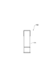
The two-layered film 50 shown in FIG. 4 only needs to be provided at least in the opening 14 closest to the daylighting port, and in the other opening 14, only one semi-specular film having polarization is used. May be. When two sheets of film 50 are attached to two or more continuous openings 14, the first and second half portions of each window 13 become smaller so that the angle θ in FIG. 5 gradually decreases with distance from the lighting port 12. The positional relationship between the specular films 51 and 52 is adjusted. That is, for any two adjacent openings 14 among two or more consecutive openings 14, the angle θ at the opening 14 closer to the lighting port 12 is the other (the farther from the lighting port 12) opening. 14 or more.
あるいは、光ダクト10の採光口12とは反対側の端部の状況により、例えば、採光口12とは反対側の端部に反射材が設けられるような場合は、角度θが採光口12から遠ざかるに従って次第に小さくなるように調整し、さらに採光口12から遠ざかる端部に近づくにつれ大きくなるように調整してもよい。このように調整することにより、採光口12とは反対側の端部付近の照度をより均一にすることができる。
Alternatively, depending on the situation of the end of the light duct 10 on the side opposite to the lighting port 12, for example, when a reflective material is provided on the end on the side opposite to the lighting port 12, the angle θ is from the lighting port 12. You may adjust so that it may become small gradually as it goes away, and also it may adjust so that it may become large as it approaches the edge part which leaves | separates from the lighting port 12 further. By adjusting in this way, the illuminance in the vicinity of the end opposite to the daylighting port 12 can be made more uniform.
以上説明した本実施形態によっても、第1実施形態と同様の作用効果が得られる。すなわち、それぞれが半鏡面性を有する2枚重ねのフィルム50が少なくとも一つの開口部14に取り付けられるので、採光口12から入射した光が、開口部14において吸収されたり必要以上にダクト本体11外に放射されたりすることなくダクト本体11内を進む。これにより、採光口12から離れている領域まで光を効率良く伝達することができ、その結果、光ダクト10の全体において照度の均一性を高めることができる。
Also according to the present embodiment described above, the same effects as those of the first embodiment can be obtained. That is, since the two-layered film 50 each having semi-specularity is attached to at least one opening 14, the light incident from the lighting port 12 is absorbed in the opening 14 or more than necessary outside the duct body 11. The inside of the duct body 11 is advanced without being radiated. Thereby, light can be efficiently transmitted to a region away from the lighting port 12, and as a result, the illuminance uniformity can be enhanced in the entire optical duct 10.
また、本実施形態によれば、各開口部14の形状及び寸法を同じにできるので、光ダクト10を容易に設計および製造することができる。また、本実施形態では、各開口部14において、2枚の半鏡面性フィルム51,52が成す角度を変えることで、光ダクト10全体における照度の均一性を細かく調整することができる。
Moreover, according to this embodiment, since the shape and dimension of each opening part 14 can be made the same, the optical duct 10 can be designed and manufactured easily. Moreover, in this embodiment, the uniformity of the illumination intensity in the whole optical duct 10 can be finely adjusted by changing the angle which the two semi-specular films 51 and 52 comprise in each opening part 14. FIG.
本実施形態では、光ダクト10の設置時において第1及び第2の半鏡面性フィルム51,52の少なくとも一方が回転可能であったが、これら2枚の半鏡面性フィルムの位置関係が固定されていてもよい。2枚の半鏡面性フィルムが成す角度の調整が完了していてその角度の変更ができない2枚重ねのフィルムを何種類か用意した場合にも、本実施形態と同様の光ダクトを作成できる。例えば、図5に示す角度θが5度ずつあるいは10度ずつ異なる複数種類の2枚重ねのフィルムを予め用意しておくことが考えられる。
In the present embodiment, at least one of the first and second semi-specular films 51 and 52 is rotatable when the optical duct 10 is installed, but the positional relationship between these two semi-specular films is fixed. It may be. An optical duct similar to that of the present embodiment can be created even when several types of two-layered films are prepared in which the angle adjustment between the two semi-specular films is completed and the angle cannot be changed. For example, it is conceivable to prepare in advance a plurality of types of two-layered films having different angles θ shown in FIG. 5 by 5 degrees or 10 degrees.
(第3実施形態)
次に、図6~12を用いて、第3実施形態に係る光ダクト100の構成を説明する。光ダクト100は、複数の窓(開口部)ではなく、ダクト本体の長手方向に沿って延びる一つの窓(開口部)を備えているという点で、第1及び第2実施形態における光ダクト10と異なる。以下では、第1及び第2実施形態と同様の点については、説明を省略するか又は簡単に説明する。 (Third embodiment)
Next, the configuration of theoptical duct 100 according to the third embodiment will be described with reference to FIGS. The optical duct 100 is provided with a single window (opening) extending along the longitudinal direction of the duct body, instead of a plurality of windows (openings), and thus the optical duct 10 in the first and second embodiments. And different. In the following, the description of the same points as in the first and second embodiments will be omitted or briefly described.
次に、図6~12を用いて、第3実施形態に係る光ダクト100の構成を説明する。光ダクト100は、複数の窓(開口部)ではなく、ダクト本体の長手方向に沿って延びる一つの窓(開口部)を備えているという点で、第1及び第2実施形態における光ダクト10と異なる。以下では、第1及び第2実施形態と同様の点については、説明を省略するか又は簡単に説明する。 (Third embodiment)
Next, the configuration of the
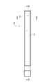
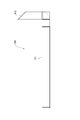
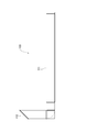
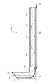
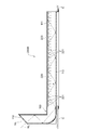
本実施形態における光ダクト100の一例を図6~12に示す。図6は光ダクト100の斜視図であり、図7~12はその六面図である。光ダクト100の本体(ダクト本体111)は略L字状を成しており、その断面形状は矩形である。ダクト本体111の一端には、光を取り入れるための採光口112が形成されている。ダクト本体111の他端は閉じられている。ダクト本体111の内壁全面には反射材が貼られている。
An example of the optical duct 100 in the present embodiment is shown in FIGS. FIG. 6 is a perspective view of the optical duct 100, and FIGS. 7 to 12 are six views thereof. The main body (duct main body 111) of the optical duct 100 is substantially L-shaped, and its cross-sectional shape is rectangular. At one end of the duct body 111, a daylighting port 112 for taking in light is formed. The other end of the duct body 111 is closed. A reflective material is attached to the entire inner wall of the duct body 111.
図6,10に示すように、室内空間に面するダクト本体111の底面には、当該本体111の長手方向に沿って延びる一つの窓113が形成されている。窓113は、ダクト本体111に形成された開口部に光学層が取り付けられることで形成されている。光学層の具体的な構成は上記第1実施形態と同様であり、従って、図3に示すような様々な変形が可能である。
As shown in FIGS. 6 and 10, one window 113 extending along the longitudinal direction of the main body 111 is formed on the bottom surface of the duct main body 111 facing the indoor space. The window 113 is formed by attaching an optical layer to an opening formed in the duct body 111. The specific configuration of the optical layer is the same as that of the first embodiment, and therefore various modifications as shown in FIG. 3 are possible.
本実施形態においても、窓113に半鏡面性フィルムが用いられるので、採光口112から入射した光が、その窓113において吸収されたり、窓113の特定の箇所において必要以上にダクト本体111外に放射されたりすることなく、ダクト本体111内を進む。これにより、採光口112から離れている領域まで光を効率良く伝達することができ、その結果、光ダクト100の全体において照度の均一性を高めることができる。
Also in this embodiment, since a semi-specular film is used for the window 113, light incident from the lighting port 112 is absorbed by the window 113, or outside the duct body 111 more than necessary at a specific portion of the window 113. It proceeds through the duct body 111 without being radiated. Thereby, light can be efficiently transmitted to a region away from the lighting port 112, and as a result, uniformity of illuminance can be enhanced in the entire light duct 100.
(第4実施形態)
次に、図13~25を用いて、第4実施形態に係る照明装置の構成を説明する。照明装置は、自然光を取り込んで放出する第3実施形態の光ダクト100に、人工照明を取り付けた装置である。人工照明は、明るさを補うための光源である。人工照明が光ダクト内部に設けられた場合、自然光と同様に外部に放射される光の照度の均一性を高めることができる。なお、図13,15,17では自然光を符号NLで示している。 (Fourth embodiment)
Next, the configuration of the illumination device according to the fourth embodiment will be described with reference to FIGS. The lighting device is a device in which artificial lighting is attached to thelight duct 100 of the third embodiment that takes in and emits natural light. Artificial lighting is a light source for supplementing brightness. When the artificial illumination is provided inside the light duct, it is possible to improve the uniformity of the illuminance of the light radiated to the outside in the same manner as natural light. In FIGS. 13, 15, and 17, natural light is indicated by reference numeral NL.
次に、図13~25を用いて、第4実施形態に係る照明装置の構成を説明する。照明装置は、自然光を取り込んで放出する第3実施形態の光ダクト100に、人工照明を取り付けた装置である。人工照明は、明るさを補うための光源である。人工照明が光ダクト内部に設けられた場合、自然光と同様に外部に放射される光の照度の均一性を高めることができる。なお、図13,15,17では自然光を符号NLで示している。 (Fourth embodiment)
Next, the configuration of the illumination device according to the fourth embodiment will be described with reference to FIGS. The lighting device is a device in which artificial lighting is attached to the
人工照明の形状及び取付位置は一つに限定されない。図13~25を用いて、その例をいくつか示す。図13~25はいずれも、光ダクト100が天井Cに埋め込まれるように照明装置が取り付けられた状態を示している。光源そのものの種類は限定されない。例えば、光源は発光ダイオード(LED)であってもよいし、蛍光灯であってもよいし、白熱灯であってもよい。
The shape and mounting position of artificial lighting are not limited to one. Some examples will be described with reference to FIGS. Each of FIGS. 13 to 25 shows a state in which the lighting device is attached so that the optical duct 100 is embedded in the ceiling C. The kind of light source itself is not limited. For example, the light source may be a light emitting diode (LED), a fluorescent lamp, or an incandescent lamp.
図13,14に示す照明装置200Aでは、複数のトラフ型の人工照明(以下では「トラフ型照明」という)210が、窓113の長手方向に沿って一列に並ぶように、ダクト本体111内部の上面に取り付けられている。ダクト本体111の長手方向におけるトラフ型照明210の取付範囲は、窓113の長手方向の寸法と略同じである。
In the lighting device 200A shown in FIGS. 13 and 14, a plurality of trough-type artificial lights (hereinafter referred to as “trough-type lights”) 210 are arranged in a line along the longitudinal direction of the window 113. It is attached to the top surface. The attachment range of the trough illumination 210 in the longitudinal direction of the duct body 111 is substantially the same as the longitudinal dimension of the window 113.
図15,16に示す照明装置200Bでは、複数のバー型の人工照明(以下では「バー型照明」という)220が、窓113の長手方向に沿って一列に並ぶように、ダクト本体111内部の上面に取り付けられている。バー型照明220は複数のLED221を有しており、これらのLED221も窓113の長手方向に沿って一列に並んでいる。ダクト本体111の長手方向におけるバー型照明220の取付範囲は、窓113の長手方向の寸法と略同じである。
In the lighting device 200B shown in FIGS. 15 and 16, a plurality of bar-type artificial lights (hereinafter referred to as “bar-type lights”) 220 are arranged in a line along the longitudinal direction of the window 113. It is attached to the top surface. The bar-type illumination 220 has a plurality of LEDs 221, and these LEDs 221 are also arranged in a line along the longitudinal direction of the window 113. The attachment range of the bar-type illumination 220 in the longitudinal direction of the duct body 111 is substantially the same as the longitudinal dimension of the window 113.
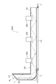
図17に示す照明装置200Cでは、複数のダウンライト230が、窓113の長手方向に沿って一列に並ぶように、ダクト本体111内部の上面に取り付けられている。ダウンライト230同士の間隔は任意に決めてよい。例えば、ダウンライト230からの光が窓113の全体に直接的に行き渡るようにその間隔を定めてもよい。
In the lighting device 200C shown in FIG. 17, a plurality of downlights 230 are attached to the upper surface inside the duct body 111 so as to be aligned in a line along the longitudinal direction of the window 113. The interval between the downlights 230 may be arbitrarily determined. For example, the interval may be set so that the light from the downlight 230 reaches the entire window 113 directly.
図18に示す照明装置200Dでは、複数のトラフ型照明210が、窓113の長手方向に沿って一列に並ぶように、ダクト本体111内部の一側面に取り付けられている。この照明装置200Dは照明装置200Aの一変形例であるともいえ、照明装置200Aとの違いはトラフ型照明210の取付位置のみである。
18, a plurality of trough-type illuminations 210 are attached to one side surface inside the duct main body 111 so as to be arranged in a line along the longitudinal direction of the window 113. The illumination device 200D can be considered as a modification of the illumination device 200A, and the only difference from the illumination device 200A is the attachment position of the trough illumination 210.
図19,20に示す照明装置200Eでは、複数のトラフ型照明210が、窓113の長手方向に沿って一列に並ぶように、ダクト本体111の底面(窓113が形成されている面)に取り付けられている。トラフ型照明210は、ダクト本体111の上方から延びているワイヤ240により支持され、室内空間に露出している。
In the lighting device 200E shown in FIGS. 19 and 20, a plurality of trough-type lights 210 are attached to the bottom surface of the duct body 111 (the surface on which the window 113 is formed) so as to be aligned in a line along the longitudinal direction of the window 113. It has been. The trough illumination 210 is supported by a wire 240 extending from above the duct body 111 and exposed to the indoor space.
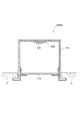
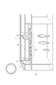
図21に示す照明装置200Fでは、複数のバー型照明220が、窓113の長手方向に沿って一列に並ぶように、窓113内部に近接した位置に設けられている。バー型照明220を取り付けるために、窓113の長手方向に沿って延び且つ断面がコ字形(squared U-shaped)の固定具250を用いる。この固定具250は、その開口部が下方を向くように、ダクト本体111の上方から延びているワイヤ240により吊られた上で窓113の内側に取り付けられる。バー型照明220は、LED221の光軸が窓113とほぼ平行になるように、固定具250の内側面に取り付けられる。バー型照明220の光がダクト本体111内に拡散するのを防ぐために、バー型照明220が取り付けられる固定具250の内部は、自然光が通るダクト本体111内の空間とは隔離されている。固定具250の内壁には反射材が貼られる。
In the illumination device 200F shown in FIG. 21, a plurality of bar-type illuminations 220 are provided at positions close to the inside of the window 113 so as to be arranged in a line along the longitudinal direction of the window 113. In order to attach the bar-shaped illumination 220, a fixture 250 extending along the longitudinal direction of the window 113 and having a U-shaped cross section is used. The fixture 250 is attached to the inside of the window 113 after being hung by a wire 240 extending from above the duct body 111 so that the opening thereof faces downward. The bar-type illumination 220 is attached to the inner surface of the fixture 250 so that the optical axis of the LED 221 is substantially parallel to the window 113. In order to prevent the light of the bar-type illumination 220 from diffusing into the duct body 111, the interior of the fixture 250 to which the bar-type illumination 220 is attached is isolated from the space within the duct body 111 through which natural light passes. A reflective material is affixed to the inner wall of the fixture 250.
図22,23に示す照明装置200Gは、図19,20に示す照明装置200Eの変形例である。トラフ型照明210がダクト本体111の外側に取り付けられているという点は照明装置200Eと同じであるが、取付箇所が照明装置200Eと異なる。照明装置200Eではトラフ型照明210が窓113の幅方向において略中央に取り付けられていたのに対して、照明装置200Gではトラフ型照明210が当該幅方向の一端部付近に取り付けられている。このトラフ型照明210は、天井Cから窓113に亘って延びる固定具251により、ダクト本体111の底面に取り付けられている。
The illumination device 200G shown in FIGS. 22 and 23 is a modification of the illumination device 200E shown in FIGS. The trough illumination 210 is attached to the outside of the duct body 111 in the same manner as the illumination device 200E, but the attachment location is different from the illumination device 200E. In the lighting device 200E, the trough-type illumination 210 is attached to the approximate center in the width direction of the window 113, whereas in the lighting device 200G, the trough-type illumination 210 is attached near one end portion in the width direction. The trough illumination 210 is attached to the bottom surface of the duct body 111 by a fixture 251 extending from the ceiling C to the window 113.
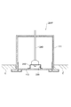
図24に示す照明装置200Hは、図21に示す照明装置200Fの変形例である。照明装置200Hが照明装置200Fと異なる点は、ワイヤ240が省略され、バー型照明220が固定具252のみにより取り付けられている、ということである。この照明装置200Hにおいても、バー型照明220が取り付けられる固定具252の内部は、自然光が通るダクト本体111内の空間とは隔離されている。当該内部を区切っている内壁には反射材が貼られる。
A lighting device 200H shown in FIG. 24 is a modification of the lighting device 200F shown in FIG. The illumination device 200H differs from the illumination device 200F in that the wire 240 is omitted and the bar-type illumination 220 is attached only by the fixture 252. Also in this lighting device 200H, the inside of the fixture 252 to which the bar-type lighting 220 is attached is isolated from the space in the duct body 111 through which natural light passes. A reflective material is affixed to the inner wall separating the interior.
このように、本実施形態に係る照明装置の構成は様々であるが、当然ながら、具体的な構造は上記のものに限定されるものではない。
As described above, the configuration of the lighting device according to the present embodiment is various, but it is needless to say that the specific structure is not limited to the above.
光源を自動的に調光、点灯又は消灯させるための照度センサを上記の任意の照明装置に取り付けてもよい。例えば図25に示すように、図13,14に示す照明装置200Aを天井Cに取り付けるとともに、室内空間の照度を測定する照度センサ300をその天井Cに取り付けてもよい。
An illuminance sensor for automatically dimming, turning on or off the light source may be attached to any of the above lighting devices. For example, as shown in FIG. 25, the illuminating device 200A shown in FIGS. 13 and 14 may be attached to the ceiling C, and the illuminance sensor 300 for measuring the illuminance in the indoor space may be attached to the ceiling C.
図25の例では、各照度センサ300が配線310により各トラフ型照明210と電気的に接続されている。各トラフ型照明210は、対応する照度センサ300により測定された照度に応じて調光、点灯又は消灯を行うための回路(図示せず)を備えている。この回路は、測定された照度が第1の閾値Th1未満になった時にトラフ型照明210を点灯させるか又はその輝度を上げ、その照度が第2の閾値Th2(ただし、Th2>Th1)以上になった時にトラフ型照明210を消灯させるか又はその輝度を下げるための回路である。
In the example of FIG. 25, each illuminance sensor 300 is electrically connected to each trough illumination 210 by a wiring 310. Each trough illumination 210 includes a circuit (not shown) for dimming, turning on or off according to the illuminance measured by the corresponding illuminance sensor 300. This circuit turns on the trough illumination 210 or increases its luminance when the measured illuminance becomes less than the first threshold Th1, and the illuminance exceeds the second threshold Th2 (where Th2> Th1). This is a circuit for turning off the trough-type illumination 210 or lowering its luminance when it becomes.
以上説明したように、本実施形態では第3実施形態と同様の光ダクトを用いているので、その第3実施形態と同様の効果を得ることができる。すなわち、採光口112から入射した自然光が、窓113において吸収されたり、窓113の特定の箇所において必要以上にダクト本体111外に放射されたりすることなく、ダクト本体111内を進む。これにより、採光口112から離れている領域まで自然光を効率良く伝達することができ、その結果、光ダクト100の全体において自然光の照度の均一性を高めることができる。
As described above, since the same optical duct as that of the third embodiment is used in this embodiment, the same effect as that of the third embodiment can be obtained. That is, the natural light incident from the lighting port 112 travels through the duct body 111 without being absorbed by the window 113 or being radiated outside the duct body 111 more than necessary at a specific portion of the window 113. As a result, natural light can be efficiently transmitted to a region away from the lighting port 112, and as a result, the uniformity of the illuminance of natural light can be enhanced throughout the light duct 100.
また、本実施形態では光ダクト100に人工照明が設けられているので、自然光だけでは明るさが不足する場合にその人工照明を調光、又は点灯させることで、任意の時間帯において必要な明るさを得ることができる。照度センサ300及び回路を設けた場合には、自然光の強さに応じて人工照明を自動的に調光、点灯又は消灯させることができるので、照明装置の利便性がより向上する。
Further, in the present embodiment, since the light duct 100 is provided with artificial illumination, when the brightness is insufficient with only natural light, the artificial illumination is dimmed or lit, so that the necessary brightness in an arbitrary time zone is obtained. You can get it. When the illuminance sensor 300 and the circuit are provided, the artificial illumination can be automatically dimmed, turned on, or turned off according to the intensity of natural light, so that the convenience of the lighting device is further improved.
以下に、光ダクトに関する実施例を示すが、その光ダクトの構成は下記の実施例に限定されるものではない。実施例1-1,1-2における光ダクトは上記第1実施形態に示すものに対応し、実施例2-1,3-1における光ダクトは上記第2実施形態に示すものに対応する。実施例4-1における照明装置は上記第4実施形態に示すものに対応する。
Hereinafter, examples relating to the optical duct will be described, but the configuration of the optical duct is not limited to the following examples. The optical ducts in Examples 1-1 and 1-2 correspond to those shown in the first embodiment, and the optical ducts in Examples 2-1 and 3-1 correspond to those shown in the second embodiment. The illumination device in Example 4-1 corresponds to that shown in the fourth embodiment.
(実施例1-1)
ミラーフィルム(スリーエム社製のDF2000MA)がラミネート加工された厚さ5mmのポリスチレン製の板材を用いて、ダクト本体を作製した。ダクト本体の断面形状は200mm×200mmの正方形とし、長さは3000mmとした。このダクト本体の一側面に、150mm×150mmの窓を三つ形成した。光ダクトの両端に関して、一端部から、該端部に一番近い窓までの距離は425mmであった。隣り合う窓間の距離は850mmであった。以下では、各窓を、光源に近い方から順に窓1、窓2、及び窓3として示す。窓3に近い方の光ダクトの端部は上記板材により閉じた。このようなダクト本体の構成の概要を図26に示す。 Example 1-1
A duct body was manufactured using a 5 mm-thick polystyrene plate material on which a mirror film (DF2000MA manufactured by 3M) was laminated. The duct body had a cross-sectional shape of 200 mm × 200 mm square and a length of 3000 mm. Three windows of 150 mm × 150 mm were formed on one side of the duct body. Regarding the both ends of the optical duct, the distance from one end to the window closest to the end was 425 mm. The distance between adjacent windows was 850 mm. Below, each window is shown aswindow 1, window 2, and window 3 in order from the one close to the light source. The end of the light duct closer to the window 3 was closed by the plate material. An outline of the structure of such a duct body is shown in FIG.
ミラーフィルム(スリーエム社製のDF2000MA)がラミネート加工された厚さ5mmのポリスチレン製の板材を用いて、ダクト本体を作製した。ダクト本体の断面形状は200mm×200mmの正方形とし、長さは3000mmとした。このダクト本体の一側面に、150mm×150mmの窓を三つ形成した。光ダクトの両端に関して、一端部から、該端部に一番近い窓までの距離は425mmであった。隣り合う窓間の距離は850mmであった。以下では、各窓を、光源に近い方から順に窓1、窓2、及び窓3として示す。窓3に近い方の光ダクトの端部は上記板材により閉じた。このようなダクト本体の構成の概要を図26に示す。 Example 1-1
A duct body was manufactured using a 5 mm-thick polystyrene plate material on which a mirror film (DF2000MA manufactured by 3M) was laminated. The duct body had a cross-sectional shape of 200 mm × 200 mm square and a length of 3000 mm. Three windows of 150 mm × 150 mm were formed on one side of the duct body. Regarding the both ends of the optical duct, the distance from one end to the window closest to the end was 425 mm. The distance between adjacent windows was 850 mm. Below, each window is shown as
各窓には、図3(d)に示すような光学層を設けた。多層光学フィルム32として、半球反射率が約0.75であり且つ偏光性を有する半鏡面性フィルムを含む、スリーエム社製の多層光学フィルムを用いた。拡散板には、三菱レーヨン社製のAcrylite(登録商標)EX432(乳白色)を用いた。開口部と拡散板との距離は50mmとした。
Each window was provided with an optical layer as shown in FIG. As the multilayer optical film 32, a multilayer optical film manufactured by 3M Co., which includes a semi-specular film having a hemispherical reflectance of about 0.75 and having polarizing properties, was used. Acrylite (registered trademark) EX432 (milky white) manufactured by Mitsubishi Rayon Co., Ltd. was used for the diffusion plate. The distance between the opening and the diffusion plate was 50 mm.
(実施例1-2)
実施例1-1と同様に、ダクト本体を作製し、窓1~3を形成した。実施例1-1と異なる点は、窓1において、スリーエム社製の多層光学フィルムの拡散シート側に、追加の拡散板(EX432)を貼り付けたことである。したがって、窓1では拡散板を2枚用いたことになる。窓2,3における光学層は、実施例1-1におけるものと同じとした。 Example 1-2
In the same manner as in Example 1-1, a duct body was produced andwindows 1 to 3 were formed. The difference from Example 1-1 is that an additional diffusion plate (EX432) is attached to the diffusion sheet side of the multilayer optical film manufactured by 3M in the window 1. Therefore, the window 1 uses two diffusion plates. The optical layers in the windows 2 and 3 were the same as those in Example 1-1.
実施例1-1と同様に、ダクト本体を作製し、窓1~3を形成した。実施例1-1と異なる点は、窓1において、スリーエム社製の多層光学フィルムの拡散シート側に、追加の拡散板(EX432)を貼り付けたことである。したがって、窓1では拡散板を2枚用いたことになる。窓2,3における光学層は、実施例1-1におけるものと同じとした。 Example 1-2
In the same manner as in Example 1-1, a duct body was produced and
(比較例1-1)
実施例1-1と同様に、ダクト本体を作製し、窓1~3を形成した。実施例1-1と異なる点は、多層光学フィルムに代えて、小さな孔が二次元状に規則正しく配列された有孔ミラーフィルム(スリーエム社製のESR)を用いたことである。有孔ミラーフィルムの開口率は、窓1~3において、それぞれ50%、70%、及び80%とした。 (Comparative Example 1-1)
In the same manner as in Example 1-1, a duct body was produced andwindows 1 to 3 were formed. The difference from Example 1-1 is that a perforated mirror film (ESR manufactured by 3M) in which small holes are regularly arranged in two dimensions is used instead of the multilayer optical film. The aperture ratio of the perforated mirror film was 50%, 70%, and 80% in windows 1 to 3, respectively.
実施例1-1と同様に、ダクト本体を作製し、窓1~3を形成した。実施例1-1と異なる点は、多層光学フィルムに代えて、小さな孔が二次元状に規則正しく配列された有孔ミラーフィルム(スリーエム社製のESR)を用いたことである。有孔ミラーフィルムの開口率は、窓1~3において、それぞれ50%、70%、及び80%とした。 (Comparative Example 1-1)
In the same manner as in Example 1-1, a duct body was produced and
(比較例1-2)
実施例1-1と同様に、ダクト本体を作製し、窓1~3を形成した。実施例1-1と異なる点は、多層光学フィルムを取り付けなかったことである。したがって、開口部は、そこから50mm離れた拡散板によってのみ覆われたことになる。 (Comparative Example 1-2)
In the same manner as in Example 1-1, a duct body was produced andwindows 1 to 3 were formed. The difference from Example 1-1 is that the multilayer optical film was not attached. Therefore, the opening is covered only by the diffusion plate 50 mm away from the opening.
実施例1-1と同様に、ダクト本体を作製し、窓1~3を形成した。実施例1-1と異なる点は、多層光学フィルムを取り付けなかったことである。したがって、開口部は、そこから50mm離れた拡散板によってのみ覆われたことになる。 (Comparative Example 1-2)
In the same manner as in Example 1-1, a duct body was produced and
(各窓における照度の比較(比較1))
実施例1-1,1-2、及び比較例1-1,1-2において作製された各光ダクトに対して同一の条件で光源(110V/40Wの白熱電球(朝日電器社製))を設置した。具体的には、光軸が、三つの窓が形成された面と45度の角度を成すように、窓1に近い光ダクトの一端に光源を設置した。そして、各光ダクトについて、光源を点灯させてから10分後に、各拡散板表面での照度を照度計(コニカミノルタ社製のCL-200)により測定した。照度の測定点は、各拡散板の表面において3箇所設けた。窓1について言うと、拡散板の中心を測定点1-2とし、光ダクトの長手方向に沿ってその中心から光源に向かって60mm進んだ箇所を測定点1-1とし、光ダクトの長手方向に沿ってその中心から反対に60mm進んだ箇所を測定点1-3とした。窓2,3についても、同様に測定点2-1乃至2-3及び3-1乃至3-3を設けた。図26では各測定点が×印で示されている。 (Comparison of illuminance in each window (Comparison 1))
A light source (110 V / 40 W incandescent bulb (manufactured by Asahi Denki Co., Ltd.)) was used under the same conditions for each of the optical ducts produced in Examples 1-1 and 1-2 and Comparative Examples 1-1 and 1-2. installed. Specifically, the light source was installed at one end of the optical duct close to thewindow 1 so that the optical axis forms an angle of 45 degrees with the surface on which the three windows are formed. For each light duct, 10 minutes after the light source was turned on, the illuminance on the surface of each diffusion plate was measured with an illuminometer (CL-200 manufactured by Konica Minolta). Three measurement points of illuminance were provided on the surface of each diffusion plate. As for the window 1, the center of the diffuser is defined as a measuring point 1-2, and a point advanced 60 mm from the center toward the light source along the longitudinal direction of the optical duct is defined as a measuring point 1-1. A point advanced 60 mm in the opposite direction along the center was defined as a measurement point 1-3. Similarly, the measurement points 2-1 to 2-3 and 3-1 to 3-3 were provided for the windows 2 and 3. In FIG. 26, each measurement point is indicated by a cross.
実施例1-1,1-2、及び比較例1-1,1-2において作製された各光ダクトに対して同一の条件で光源(110V/40Wの白熱電球(朝日電器社製))を設置した。具体的には、光軸が、三つの窓が形成された面と45度の角度を成すように、窓1に近い光ダクトの一端に光源を設置した。そして、各光ダクトについて、光源を点灯させてから10分後に、各拡散板表面での照度を照度計(コニカミノルタ社製のCL-200)により測定した。照度の測定点は、各拡散板の表面において3箇所設けた。窓1について言うと、拡散板の中心を測定点1-2とし、光ダクトの長手方向に沿ってその中心から光源に向かって60mm進んだ箇所を測定点1-1とし、光ダクトの長手方向に沿ってその中心から反対に60mm進んだ箇所を測定点1-3とした。窓2,3についても、同様に測定点2-1乃至2-3及び3-1乃至3-3を設けた。図26では各測定点が×印で示されている。 (Comparison of illuminance in each window (Comparison 1))
A light source (110 V / 40 W incandescent bulb (manufactured by Asahi Denki Co., Ltd.)) was used under the same conditions for each of the optical ducts produced in Examples 1-1 and 1-2 and Comparative Examples 1-1 and 1-2. installed. Specifically, the light source was installed at one end of the optical duct close to the
実施例1-1,1-2、及び比較例1-1,1-2の各光ダクトについての各測定点での照度を下記表1に示す。

The illuminance at each measurement point for each of the optical ducts of Examples 1-1 and 1-2 and Comparative Examples 1-1 and 1-2 is shown in Table 1 below.
実施例1-1,1-2、及び比較例1-1,1-2の各光ダクトについての、各窓での平均照度及び標準偏差と、その平均照度及び標準偏差の各平均値とを下記表2に示す。
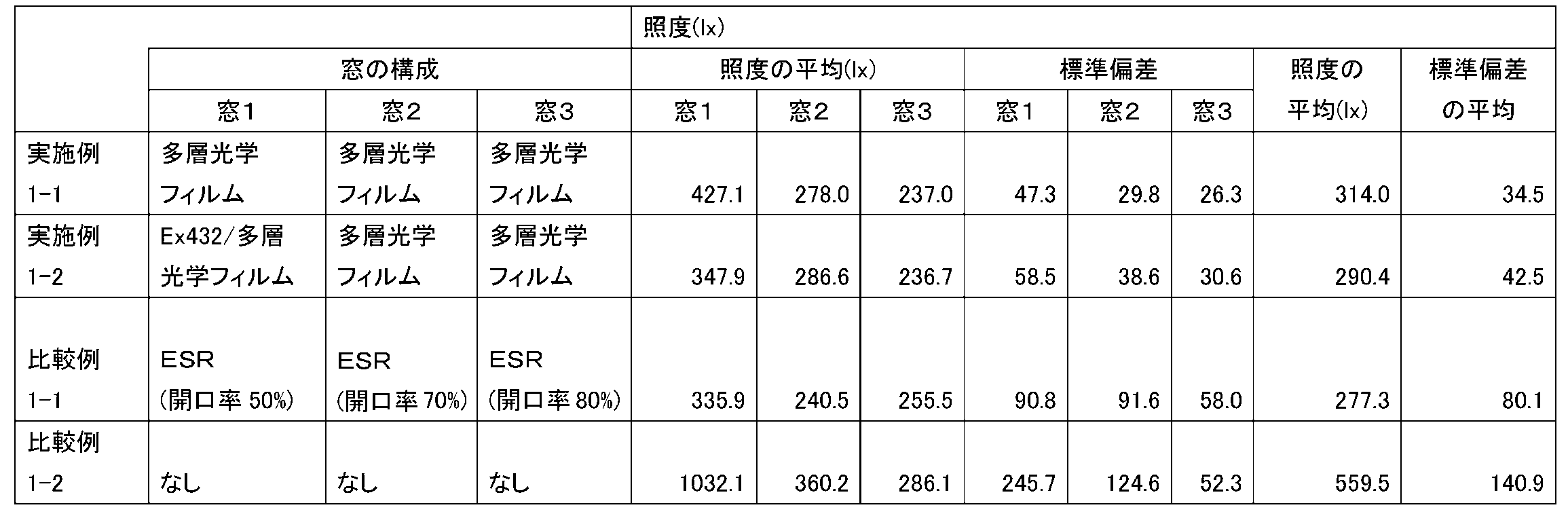
For the light ducts of Examples 1-1 and 1-2 and Comparative Examples 1-1 and 1-2, the average illuminance and standard deviation at each window, and the average values of the average illuminance and standard deviation, respectively. It is shown in Table 2 below.
(実施例2-1)
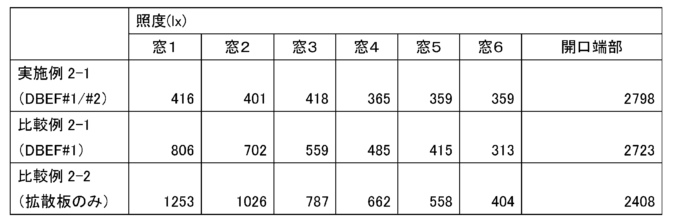
ミラーフィルム(スリーエム社製のESR)がラミネート加工された厚さ5mmのポリスチレン製の板材を用いて、ダクト本体を作製した。ダクト本体の断面形状は200mm×200mmの正方形とし、長さは3300mmとした。このダクト本体の一側面に、100mm×100mmの窓を六つ形成した。光ダクトの両端に関して、一端部から、該端部に一番近い窓までの距離は225mmであった。隣り合う窓間の距離は450mmであった。以下では、各窓を、光源に近い方から順に窓1、窓2、…、窓6として示す。窓6に近い方の光ダクトの端部は開放した。このようなダクト本体の構成の概要を図27に示す。 Example 2-1
A duct body was manufactured using a 5 mm thick polystyrene plate material on which a mirror film (ESR manufactured by 3M) was laminated. The duct body had a cross-sectional shape of 200 mm × 200 mm square and a length of 3300 mm. Six windows of 100 mm × 100 mm were formed on one side of the duct body. Regarding the both ends of the optical duct, the distance from one end to the window closest to the end was 225 mm. The distance between adjacent windows was 450 mm. Below, each window is shown aswindow 1, window 2,..., Window 6 in order from the side closer to the light source. The end of the light duct closer to the window 6 was opened. An outline of the structure of such a duct body is shown in FIG.
ミラーフィルム(スリーエム社製のESR)がラミネート加工された厚さ5mmのポリスチレン製の板材を用いて、ダクト本体を作製した。ダクト本体の断面形状は200mm×200mmの正方形とし、長さは3300mmとした。このダクト本体の一側面に、100mm×100mmの窓を六つ形成した。光ダクトの両端に関して、一端部から、該端部に一番近い窓までの距離は225mmであった。隣り合う窓間の距離は450mmであった。以下では、各窓を、光源に近い方から順に窓1、窓2、…、窓6として示す。窓6に近い方の光ダクトの端部は開放した。このようなダクト本体の構成の概要を図27に示す。 Example 2-1
A duct body was manufactured using a 5 mm thick polystyrene plate material on which a mirror film (ESR manufactured by 3M) was laminated. The duct body had a cross-sectional shape of 200 mm × 200 mm square and a length of 3300 mm. Six windows of 100 mm × 100 mm were formed on one side of the duct body. Regarding the both ends of the optical duct, the distance from one end to the window closest to the end was 225 mm. The distance between adjacent windows was 450 mm. Below, each window is shown as
窓1~5には、図4(b)に示すような光学層を取り付けた。第1及び第2の半鏡面性フィルムには、反射率が約0.50であり且つ偏光性を有するスリーエム社製のDBEFを用いた。拡散板には、三菱レーヨン社製のAcrylite(登録商標)EX432(白)を用いた。窓1~5において、2枚の半鏡面性フィルムが成す角度をそれぞれ、70度、60度、50度、50度、及び35度とした。一方、窓6には、1枚の半鏡面性フィルム(DBEF)に1枚の白の拡散板(EX432)を貼り付けて成る光学層を取り付けた。
The optical layers as shown in FIG. 4B were attached to the windows 1 to 5. As the first and second semi-specular films, DBEF manufactured by 3M having a reflectivity of about 0.50 and having a polarizing property was used. Acrylite (registered trademark) EX432 (white) manufactured by Mitsubishi Rayon Co., Ltd. was used as the diffusion plate. In windows 1 to 5, the angles formed by the two semi-specular films were 70 degrees, 60 degrees, 50 degrees, 50 degrees, and 35 degrees, respectively. On the other hand, an optical layer formed by attaching one white diffuser plate (EX432) to one semi-specular film (DBEF) was attached to the window 6.
(比較例2-1)
実施例2-1と同様に、ダクト本体を作製し、窓1~6を形成した。実施例2-1と異なる点は、すべての窓において、1枚の偏光性を有する半鏡面性フィルム(DBEF)と1枚の白の拡散板(EX432)とから成る光学層を取り付けたことである。これは、実施例2-1における窓6における光学層を、すべての窓に適用したことを意味する。 (Comparative Example 2-1)
In the same manner as in Example 2-1, a duct body was produced andwindows 1 to 6 were formed. The difference from Example 2-1 is that an optical layer consisting of one polarizing half-specular film (DBEF) and one white diffusion plate (EX432) is attached to all windows. is there. This means that the optical layer in the window 6 in Example 2-1 was applied to all windows.
実施例2-1と同様に、ダクト本体を作製し、窓1~6を形成した。実施例2-1と異なる点は、すべての窓において、1枚の偏光性を有する半鏡面性フィルム(DBEF)と1枚の白の拡散板(EX432)とから成る光学層を取り付けたことである。これは、実施例2-1における窓6における光学層を、すべての窓に適用したことを意味する。 (Comparative Example 2-1)
In the same manner as in Example 2-1, a duct body was produced and
(比較例2-2)
実施例2-1と同様に、ダクト本体を作製し、窓1~6を形成した。実施例2-1と異なる点は、すべての窓において、1枚の白の拡散板(EX432)のみから成る光学層を取り付けたことである。 (Comparative Example 2-2)
In the same manner as in Example 2-1, a duct body was produced andwindows 1 to 6 were formed. The difference from Example 2-1 is that an optical layer composed of only one white diffusion plate (EX432) is attached to all windows.
実施例2-1と同様に、ダクト本体を作製し、窓1~6を形成した。実施例2-1と異なる点は、すべての窓において、1枚の白の拡散板(EX432)のみから成る光学層を取り付けたことである。 (Comparative Example 2-2)
In the same manner as in Example 2-1, a duct body was produced and
(各窓における照度の比較(比較2))
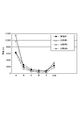
実施例2-1,及び比較例2-1,2-2において作製された各光ダクトに対して同一の条件で光源(110V/40Wの白熱電球(朝日電器社製))を設置した。具体的には、光軸が光ダクトの長手方向と一致するように、窓1に近い光ダクトの一端に光源を設置した。そして、光源を点灯させてから10分後に、各拡散板の表面の中心での照度を照度計(コニカミノルタ社製のCL-200)により測定した。この測定結果を下記表3及び図28に示す。
(Comparison of illuminance in each window (Comparison 2))
A light source (110 V / 40 W incandescent bulb (manufactured by Asahi Denki)) was installed under the same conditions for each of the optical ducts produced in Example 2-1 and Comparative Examples 2-1 and 2-2. Specifically, a light source was installed at one end of the optical duct close to thewindow 1 so that the optical axis coincided with the longitudinal direction of the optical duct. Then, 10 minutes after turning on the light source, the illuminance at the center of the surface of each diffusion plate was measured with an illuminometer (CL-200 manufactured by Konica Minolta). The measurement results are shown in Table 3 below and FIG.
実施例2-1,及び比較例2-1,2-2において作製された各光ダクトに対して同一の条件で光源(110V/40Wの白熱電球(朝日電器社製))を設置した。具体的には、光軸が光ダクトの長手方向と一致するように、窓1に近い光ダクトの一端に光源を設置した。そして、光源を点灯させてから10分後に、各拡散板の表面の中心での照度を照度計(コニカミノルタ社製のCL-200)により測定した。この測定結果を下記表3及び図28に示す。
A light source (110 V / 40 W incandescent bulb (manufactured by Asahi Denki)) was installed under the same conditions for each of the optical ducts produced in Example 2-1 and Comparative Examples 2-1 and 2-2. Specifically, a light source was installed at one end of the optical duct close to the
(実施例3-1)
実施例2-1と同様に、ダクト本体を作製し、窓1~6を形成した。窓1~5における2枚の半鏡面性フィルム(それぞれの反射率が約0.50である2枚のDBEF)が成す角度はそれぞれ、70度、50度、45度、45度、及び20度とした。窓6の構成は実施例2-1と同じとした。 Example 3-1
In the same manner as in Example 2-1, a duct body was produced andwindows 1 to 6 were formed. The angles formed by two semi-specular films (two DBEFs each having a reflectance of about 0.50) in windows 1 to 5 are 70 degrees, 50 degrees, 45 degrees, 45 degrees, and 20 degrees, respectively. It was. The configuration of the window 6 was the same as in Example 2-1.
実施例2-1と同様に、ダクト本体を作製し、窓1~6を形成した。窓1~5における2枚の半鏡面性フィルム(それぞれの反射率が約0.50である2枚のDBEF)が成す角度はそれぞれ、70度、50度、45度、45度、及び20度とした。窓6の構成は実施例2-1と同じとした。 Example 3-1
In the same manner as in Example 2-1, a duct body was produced and
(比較例3-1)
実施例3-1と同様に、ダクト本体を作製し、窓1~6を形成した。実施例3-1と異なる点は、半鏡面性フィルムに代えて、小さな孔が二次元状に規則正しく配列された有孔ミラーフィルム(スリーエム社製のESR)を用いたことである。有孔ミラーフィルムの開口率は、窓1~5において、それぞれ30%、50%、70%、80%、及び90%とした。窓6では、有孔ミラーフィルムを用いることなく白の拡散板(EX432)のみを取り付けた。 (Comparative Example 3-1)
In the same manner as in Example 3-1, a duct body was produced andwindows 1 to 6 were formed. The difference from Example 3-1 is that a perforated mirror film (ESR manufactured by 3M) in which small holes are regularly arranged in two dimensions is used instead of the semi-specular film. The aperture ratio of the perforated mirror film was 30%, 50%, 70%, 80%, and 90% in windows 1 to 5, respectively. In the window 6, only a white diffuser plate (EX432) was attached without using a perforated mirror film.
実施例3-1と同様に、ダクト本体を作製し、窓1~6を形成した。実施例3-1と異なる点は、半鏡面性フィルムに代えて、小さな孔が二次元状に規則正しく配列された有孔ミラーフィルム(スリーエム社製のESR)を用いたことである。有孔ミラーフィルムの開口率は、窓1~5において、それぞれ30%、50%、70%、80%、及び90%とした。窓6では、有孔ミラーフィルムを用いることなく白の拡散板(EX432)のみを取り付けた。 (Comparative Example 3-1)
In the same manner as in Example 3-1, a duct body was produced and
(比較例3-2)
比較例2-2と同じ光ダクトを用いた。 (Comparative Example 3-2)
The same optical duct as in Comparative Example 2-2 was used.
比較例2-2と同じ光ダクトを用いた。 (Comparative Example 3-2)
The same optical duct as in Comparative Example 2-2 was used.
(各窓における照度の比較(比較3))
実施例3-1,及び比較例3-1,3-2において作製された各光ダクトに対して、上記比較2と同様に光源を設置して点灯させ、光源を点灯させてから10分後に、各拡散板の表面の中心での照度を照度計(コニカミノルタ社製のCL-200)により測定した。この測定結果を下記表4及び図29に示す。

(Comparison of illuminance in each window (Comparison 3))
For each optical duct manufactured in Example 3-1 and Comparative Examples 3-1 and 3-2, a light source was installed and turned on in the same manner as in Comparative Example 2, and 10 minutes after the light source was turned on. The illuminance at the center of the surface of each diffusion plate was measured with an illuminometer (CL-200 manufactured by Konica Minolta). The measurement results are shown in Table 4 below and FIG.
実施例3-1,及び比較例3-1,3-2において作製された各光ダクトに対して、上記比較2と同様に光源を設置して点灯させ、光源を点灯させてから10分後に、各拡散板の表面の中心での照度を照度計(コニカミノルタ社製のCL-200)により測定した。この測定結果を下記表4及び図29に示す。
For each optical duct manufactured in Example 3-1 and Comparative Examples 3-1 and 3-2, a light source was installed and turned on in the same manner as in Comparative Example 2, and 10 minutes after the light source was turned on. The illuminance at the center of the surface of each diffusion plate was measured with an illuminometer (CL-200 manufactured by Konica Minolta). The measurement results are shown in Table 4 below and FIG.
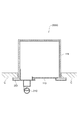
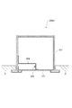
(実施例4-1)
図30に示すような照明装置を作製した。具体的には、ミラーフィルム(スリーエム社製のDF2000MA)がラミネート加工された厚さ5mmのポリスチレン製の板材を用いて、L字状のダクト本体を作製した。ダクト本体の断面形状は幅65mm×高さ45mmの矩形とし、総延長は815mmとした。一端部に形成した採光口から角までの長さ(鉛直部分の長さ)は255mmであり、その角から他端部までの長さ(水平方向の長さ)は560mmであった。なお、当該他端部は上記板材により閉じた。 Example 4-1
A lighting device as shown in FIG. 30 was produced. Specifically, an L-shaped duct body was prepared using a 5 mm-thick polystyrene plate material on which a mirror film (DF2000MA manufactured by 3M) was laminated. The cross-sectional shape of the duct body was a rectangle with a width of 65 mm and a height of 45 mm, and the total extension was 815 mm. The length from the lighting port formed at one end to the corner (the length of the vertical portion) was 255 mm, and the length from the corner to the other end (the length in the horizontal direction) was 560 mm. The other end was closed by the plate material.
このダクト本体の水平部分の底面に500mm×55mmの窓を形成した。この窓には、図3(c)に示すような光学層を設けた。光学層として、半球反射率が約0.75であり(したがって、半球透過率は約0.25)且つ偏光性を有する半鏡面性フィルムを含む、スリーエム社製の多層光学フィルムを用いた。
A 500 mm × 55 mm window was formed on the bottom surface of the horizontal portion of the duct body. The window was provided with an optical layer as shown in FIG. As the optical layer, a multilayer optical film manufactured by 3M Co., which includes a semi-specular film having a hemispherical reflectance of about 0.75 (thus, a hemispherical transmittance of about 0.25) and a polarizing property was used.
ダクト本体の水平部分の一つの内側面には二つのバー型照明を人工照明として取り付けた。このバー型照明は、12個のLED(日亜化学工業社製のNS6W083B。110V/12W)が一列に並んだ照明装置である。したがって、この人工照明は合計24個のLEDを備えている。LED同士の間隔は20mmとした。
二 つ Two bar-type lights were installed as artificial lights on one inner surface of the horizontal part of the duct body. This bar-type illumination is an illumination device in which 12 LEDs (NS6W083B manufactured by Nichia Corporation, 110V / 12W) are arranged in a line. Therefore, this artificial illumination has a total of 24 LEDs. The distance between the LEDs was 20 mm.
(比較例4-1)
実施例4-1と同様に、ダクト本体を作製し、窓を形成し、人工照明を取り付けた。実施例4-1と異なる点は、多層光学フィルムに代えて、透過率が約30%である光拡散フィルム(スリーエム社製の3635-30)を用いたことである。 (Comparative Example 4-1)
In the same manner as in Example 4-1, a duct body was produced, a window was formed, and artificial lighting was attached. The difference from Example 4-1 is that a light diffusing film (3635-30 manufactured by 3M) having a transmittance of about 30% was used instead of the multilayer optical film.
(比較例4-2)
実施例4-1と同様に、ダクト本体を作製し、窓を形成し、人工照明を取り付けた。実施例4-1と異なる点は、多層光学フィルムに代えて、透過率が約87%であるアクリル・シート(クラレ社製の422L)を用いたことである。 (Comparative Example 4-2)
In the same manner as in Example 4-1, a duct body was produced, a window was formed, and artificial lighting was attached. A difference from Example 4-1 is that an acrylic sheet (422L manufactured by Kuraray Co., Ltd.) having a transmittance of about 87% was used instead of the multilayer optical film.
(比較例4-3)
実施例4-1と同様に、ダクト本体を作製し、窓を形成し、人工照明を取り付けた。実施例4-1と異なる点は、多層光学フィルムに代えて、透過率が約55%であるアクリル・シート(住友化学社製のE032)を用いたことである。 (Comparative Example 4-3)
In the same manner as in Example 4-1, a duct body was produced, a window was formed, and artificial lighting was attached. The difference from Example 4-1 is that an acrylic sheet (E032 manufactured by Sumitomo Chemical Co., Ltd.) having a transmittance of about 55% was used instead of the multilayer optical film.
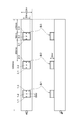
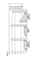
(窓における照度の比較(比較4))
実施例4-1、及び比較例4-1~4-3において作製された各照明装置に、110V/35Wのハロゲン・ランプ(ウシオライティング社製)を、自然光を模した光源として設置した。具体的には、光軸が光ダクトの一側面と45度の角度を成すようにそのハロゲン・ランプを採光口に設置した。そして、各照明装置について、光源を点灯させてから10分後に、窓表面での照度を照度計(コニカミノルタ社製のCL-200)により測定した。照度の測定点は、窓の表面において5箇所設けた。具体的には、採光口に近い方の窓の端部から35mm離れた箇所に測定点Aを設け、この測定点Aから110mm進む毎に測定点B~Eを設けた。各測定点A~Eはいずれも、窓の幅方向において略中央に位置している。図30では各測定点が丸印で示されている。 (Comparison of illuminance in windows (Comparison 4))
A 110 V / 35 W halogen lamp (manufactured by Ushio Lighting Co., Ltd.) was installed as a light source simulating natural light in each of the lighting devices manufactured in Example 4-1 and Comparative Examples 4-1 to 4-3. Specifically, the halogen lamp was installed in the lighting port so that the optical axis forms an angle of 45 degrees with one side surface of the optical duct. For each lighting device, the illuminance on the window surface was measured with an illuminometer (CL-200 manufactured by Konica Minolta) 10 minutes after the light source was turned on. Five measurement points of illuminance were provided on the surface of the window. Specifically, a measurement point A is provided at a location 35 mm away from the end of the window closer to the lighting port, and measurement points B to E are provided every time 110 mm travels from the measurement point A. Each of the measurement points A to E is located substantially at the center in the width direction of the window. In FIG. 30, each measurement point is indicated by a circle.
まず、ハロゲン・ランプのみを点灯させた場合(自然光のみの利用を想定した場合)の各測定点での照度を下記表5及び図31に示す。また、5地点での照度の平均及び標準偏差を表5に示す。
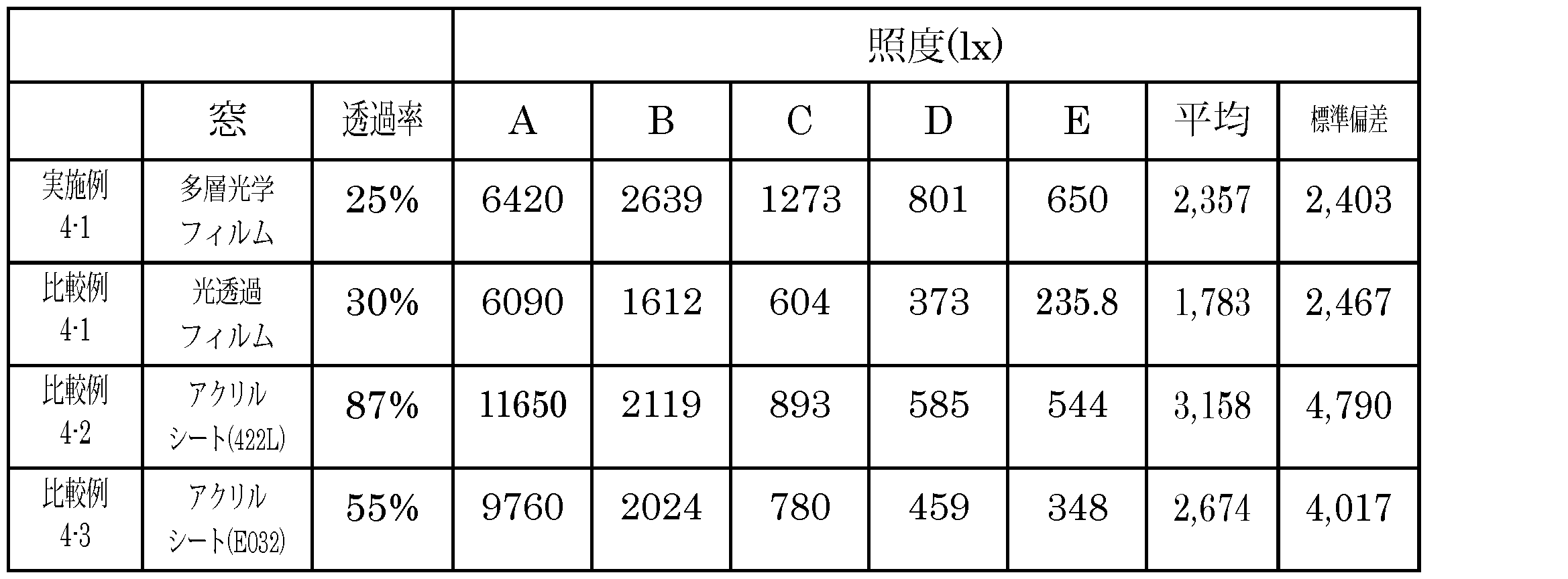
First, the illuminance at each measurement point when only the halogen lamp is turned on (when only natural light is used) is shown in Table 5 and FIG. Table 5 shows the average and standard deviation of illuminance at five points.
次に、ハロゲン・ランプ及びバー型照明のすべてを点灯させた場合(人工光を自然光の補助として用いることを想定した場合)の、各測定点での照度と、その平均及び標準偏差とを下記表6に示す。

Next, the illuminance at each measurement point and its average and standard deviation when all of the halogen lamp and bar-type lighting are turned on (assuming that artificial light is used as an auxiliary to natural light) are as follows: Table 6 shows.
以上、本発明の実施形態及び実施例を詳細に説明した。しかし、本発明は上記の実施形態及び実施例に限定されるものではない。本発明は、その要旨を逸脱しない範囲で様々な変形が可能である。
The embodiments and examples of the present invention have been described in detail above. However, the present invention is not limited to the above-described embodiments and examples. The present invention can be variously modified without departing from the gist thereof.
光ダクトの形状や寸法は上記実施形態及び実施例に限定されない。例えば、ダクト本体はその長手方向に沿って直線状である必要はなく、全体又は一部が曲がっていてもよい。また、ダクト本体が途中で分岐していてもよい。更にダクト本体の断面形状が矩形以外(例えば円)であってもよい。
The shape and dimensions of the optical duct are not limited to the above embodiment and examples. For example, the duct body does not have to be linear along its longitudinal direction, and may be bent entirely or partially. Moreover, the duct main body may branch on the way. Furthermore, the cross-sectional shape of the duct body may be other than a rectangle (for example, a circle).
窓(開口部)の位置や形状も任意である。例えば、矩形以外(例えば円)の形状の窓を任意の位置に形成してもよい。複数の窓を設ける場合には、隣り合う二つの窓の間隔は同じでなくてもよい。窓は一列に正確に並んでいる必要はなく、ダクト本体の幅方向における窓の位置が互いに異なっていてもよい。また、ダクト本体の長手方向に沿って並ぶ窓の列が2列以上であってもよい。
The position and shape of the window (opening) are also arbitrary. For example, you may form the window of shapes other than a rectangle (for example, circle) in arbitrary positions. When providing a plurality of windows, the interval between two adjacent windows may not be the same. The windows do not need to be arranged accurately in a line, and the positions of the windows in the width direction of the duct body may be different from each other. Two or more windows may be arranged in the longitudinal direction of the duct body.
採光口の位置はダクト本体の長手方向の一端部である必要はなく、長手方向における途中の任意の地点に採光口が形成されてもよい。また、採光口の個数は複数でもよい。
The position of the lighting port does not need to be one end in the longitudinal direction of the duct body, and the lighting port may be formed at an arbitrary point in the longitudinal direction. Moreover, the number of the lighting openings may be plural.
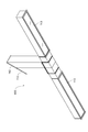
したがって、光ダクトを設置場所に応じて設計することができる。図32に示す、二つの隣接するL字状の光ダクトからなるT字状の光ダクト又は照明装置400や、図33に示す直線状の光ダクト又は照明装置410は、第3又は第4実施形態の変形である。図34に示す光ダクト10は第1又は第2実施形態の変形であり、この光ダクト10は、太陽光Lを室内に取り入れるために建物B内に配置されている。
Therefore, the optical duct can be designed according to the installation location. The T-shaped light duct or lighting device 400 composed of two adjacent L-shaped light ducts shown in FIG. 32 or the linear light duct or lighting device 410 shown in FIG. 33 is the third or fourth embodiment. It is a variation of the form. The optical duct 10 shown in FIG. 34 is a modification of the first or second embodiment, and the optical duct 10 is disposed in the building B in order to take sunlight L into the room.
複数の窓が形成されている光ダクト(例えば、第1及び第2実施形態に係る光ダクト10)と上記第4実施形態における各種の人工照明とを備える照明装置も、本発明の範囲内である。
A lighting device including an optical duct in which a plurality of windows are formed (for example, the optical duct 10 according to the first and second embodiments) and the various artificial lights in the fourth embodiment is also within the scope of the present invention. is there.
10…光ダクト、11…ダクト本体、12…採光口、13…窓、14…開口部、21…半鏡面性フィルム、22…ビーズコーティング、23…拡散シート、31,32…多層光学フィルム、41…管状部材、42…拡散板、50…2枚重ねのフィルム、51…第1の半鏡面性フィルム、52…第2の半鏡面性フィルム、61…拡散板、62…管状部材、100…光ダクト、111…ダクト本体、112…採光口、113…窓、200A~200H…照明装置、210…トラフ型照明(光源)、220…バー型照明(光源)、230…ダウンライト(光源)、300…照度センサ、400及び410…光ダクト又は照明装置。
DESCRIPTION OFSYMBOLS 10 ... Light duct, 11 ... Duct body, 12 ... Daylighting port, 13 ... Window, 14 ... Opening part, 21 ... Semi-specular film, 22 ... Bead coating, 23 ... Diffusion sheet, 31, 32 ... Multilayer optical film, 41 DESCRIPTION OF SYMBOLS ... Tubular member, 42 ... Diffuser plate, 50 ... Two-layer film, 51 ... First semi-specular film, 52 ... Second semi-specular film, 61 ... Diffuser plate, 62 ... Tubular member, 100 ... Light Duct, 111 ... Duct body, 112 ... Daylight opening, 113 ... Window, 200A to 200H ... Illumination device, 210 ... Trough illumination (light source), 220 ... Bar illumination (light source), 230 ... Downlight (light source), 300 ... illuminance sensors, 400 and 410 ... light ducts or lighting devices.
DESCRIPTION OF
Claims (14)
- 少なくとも一つの採光口と、少なくとも一つの開口部とが形成されたダクト本体と、
前記少なくとも一つの開口部のそれぞれに取り付けられた、半鏡面性を有するフィルムと
を備える光ダクト。 A duct body formed with at least one daylight opening and at least one opening;
An optical duct comprising: a film having semi-specularity attached to each of the at least one opening. - 複数の前記開口部が前記ダクト本体の長手方向に並んで形成されている、
請求項1に記載の光ダクト。 A plurality of the openings are formed side by side in the longitudinal direction of the duct body.
The optical duct according to claim 1. - 前記フィルムの半球反射率が0.70~0.90である、
請求項1又は2に記載の光ダクト。 The hemispherical reflectance of the film is 0.70-0.90,
The optical duct according to claim 1 or 2. - 前記ダクト本体の内部に面する前記フィルムの片面がビーズコーティングされている、
請求項3に記載の光ダクト。 One side of the film facing the inside of the duct body is bead coated,
The optical duct according to claim 3. - 少なくとも前記採光口に最も近い前記開口部に、それぞれが偏光性および半鏡面性を有する第1のフィルム及び第2のフィルムが取り付けられており、
前記第2のフィルムが、前記第1のフィルムに対して0度より大きく且つ90度未満の角度をなすように、該第1のフィルムに重ねられている、
請求項2に記載の光ダクト。 A first film and a second film, each having polarization and semi-specularity, are attached to at least the opening closest to the daylighting port,
The second film is overlaid on the first film so as to form an angle of greater than 0 degrees and less than 90 degrees with respect to the first film;
The optical duct according to claim 2. - 前記複数の開口部のうち連続する2以上の開口部に前記第1及び第2のフィルムが取り付けられており、
前記連続する2以上の開口部のうち隣り合う任意の二つの開口部について、前記採光口に近い方の開口部における前記第1のフィルムと前記第2のフィルムとの成す角度が、他方の開口部における前記第1のフィルムと前記第2のフィルムとの成す角度以上である、
請求項5に記載の光ダクト。 The first and second films are attached to two or more continuous openings of the plurality of openings,
For any two adjacent openings of the two or more continuous openings, the angle formed by the first film and the second film in the opening closer to the daylighting opening is the other opening. Is an angle formed by the first film and the second film in the portion,
The optical duct according to claim 5. - 前記第1及び第2のフィルムの半球反射率がそれぞれ0.20~0.80である、
請求項5又は6に記載の光ダクト。 The hemispherical reflectances of the first and second films are 0.20 to 0.80, respectively.
The optical duct according to claim 5 or 6. - 前記第1及び第2のフィルムの一方が他方に対して回転可能に設けられており、これにより前記角度が調整可能である、
請求項5~7のいずれか一項に記載の光ダクト。 One of the first and second films is provided to be rotatable with respect to the other, whereby the angle can be adjusted.
The optical duct according to any one of claims 5 to 7. - 前記複数の開口部の形状及び寸法が略同一である、
請求項5~8のいずれか一項に記載の光ダクト。 The shapes and dimensions of the plurality of openings are substantially the same,
The optical duct according to any one of claims 5 to 8. - 請求項1~9のいずれか一項に記載の光ダクトと、
前記光ダクトに設けられた光源と
を備える照明装置。 An optical duct according to any one of claims 1 to 9,
A lighting device comprising a light source provided in the light duct. - 前記光源が前記ダクト本体の内部に設けられている、
請求項10に記載の照明装置。 The light source is provided inside the duct body;
The lighting device according to claim 10. - 前記光源が、前記開口部が形成されている前記ダクト本体の面の下方に設けられている、
請求項10に記載の照明装置。 The light source is provided below the surface of the duct body in which the opening is formed.
The lighting device according to claim 10. - 照度を測定する照度センサと、
前記照度センサにより測定された照度が第1の閾値未満である場合に前記光源を点灯させ、該照度が第2の閾値以上である場合に前記光源を消灯させる回路であって、該第2の閾値が該第1の閾値よりも大きい、該回路と
を更に備える請求項10~12のいずれか一項に記載の照明装置。 An illuminance sensor for measuring illuminance;
A circuit that turns on the light source when the illuminance measured by the illuminance sensor is less than a first threshold, and turns off the light source when the illuminance is greater than or equal to a second threshold; The lighting device according to any one of claims 10 to 12, further comprising the circuit having a threshold value greater than the first threshold value. - 照度を測定する照度センサと、
前記照度センサにより測定された照度が第1の閾値未満である場合に前記光源の輝度を上げ、該測定された照度が第2の閾値以上である場合に前記光源の輝度を下げる回路であって、該第2の閾値が該第1の閾値よりも大きい、該回路と
を更に備える請求項10~12のいずれか一項に記載の照明装置。 An illuminance sensor for measuring illuminance;
A circuit that increases the luminance of the light source when the illuminance measured by the illuminance sensor is less than a first threshold, and decreases the luminance of the light source when the measured illuminance is greater than or equal to a second threshold. The lighting device according to any one of claims 10 to 12, further comprising the circuit in which the second threshold value is larger than the first threshold value.
Priority Applications (1)
| Application Number | Priority Date | Filing Date | Title |
|---|---|---|---|
| JP2013510912A JP6192535B2 (en) | 2011-04-22 | 2012-02-23 | Light duct and lighting device |
Applications Claiming Priority (2)
| Application Number | Priority Date | Filing Date | Title |
|---|---|---|---|
| JP2011-096358 | 2011-04-22 | ||
| JP2011096358 | 2011-04-22 |
Publications (1)
| Publication Number | Publication Date |
|---|---|
| WO2012144268A1 true WO2012144268A1 (en) | 2012-10-26 |
Family
ID=47041390
Family Applications (1)
| Application Number | Title | Priority Date | Filing Date |
|---|---|---|---|
| PCT/JP2012/054470 WO2012144268A1 (en) | 2011-04-22 | 2012-02-23 | Light duct and lighting device |
Country Status (2)
| Country | Link |
|---|---|
| JP (1) | JP6192535B2 (en) |
| WO (1) | WO2012144268A1 (en) |
Cited By (7)
| Publication number | Priority date | Publication date | Assignee | Title |
|---|---|---|---|---|
| US9046637B1 (en) | 2014-02-25 | 2015-06-02 | 3M Innovative Properties Company | Tubular lighting systems with inner and outer structured surfaces |
| WO2015156986A1 (en) * | 2014-04-07 | 2015-10-15 | 3M Innovative Properties Company | Light horn arrays for ducted lighting systems |
| US9464773B2 (en) | 2013-04-11 | 2016-10-11 | 3M Innovative Properties Company | Illuminated light duct joint |
| US9476554B2 (en) | 2012-10-30 | 2016-10-25 | 3M Innovative Properties Company | Rectangular light duct extraction |
| US9791128B2 (en) | 2012-10-30 | 2017-10-17 | 3M Innovative Properties Company | Curved light duct extraction |
| US10161593B2 (en) | 2014-02-25 | 2018-12-25 | 3M Innovative Properties Company | Solid state lighting device with virtual filament(s) |
| CN109891286A (en) * | 2016-11-03 | 2019-06-14 | 巴斯夫欧洲公司 | Daylight illuminating system |
Citations (5)
| Publication number | Priority date | Publication date | Assignee | Title |
|---|---|---|---|---|
| JPS5936511U (en) * | 1982-08-31 | 1984-03-07 | 松下電工株式会社 | lighting ceiling device |
| JPH06111610A (en) * | 1992-09-25 | 1994-04-22 | Sanyo Electric Co Ltd | Sunlight collecting device |
| JPH112726A (en) * | 1997-06-11 | 1999-01-06 | Toshiba Lighting & Technol Corp | Light guide device, condensing device and illumination system |
| JP2008084749A (en) * | 2006-09-28 | 2008-04-10 | Toto Ltd | Light-emitting device for optical duct |
| WO2009105450A1 (en) * | 2008-02-22 | 2009-08-27 | 3M Innovative Properties Company | Backlights having selected output light flux distributions and display systems using same |
Family Cites Families (9)
| Publication number | Priority date | Publication date | Assignee | Title |
|---|---|---|---|---|
| JPH1125726A (en) * | 1997-06-30 | 1999-01-29 | Toshiba Lighting & Technol Corp | Light guide apparatus and illuminating system |
| JP2000131511A (en) * | 1998-08-19 | 2000-05-12 | Nippon Kayaku Co Ltd | Reflecting semi-transmitting plate |
| JP2000111712A (en) * | 1998-10-02 | 2000-04-21 | Toyota Motor Corp | Light diffusion element and high mount stop lamp for vehicle using the element |
| JP4967274B2 (en) * | 2004-08-06 | 2012-07-04 | 東レ株式会社 | Light reflecting film and surface light source using the same |
| JP4570571B2 (en) * | 2006-01-16 | 2010-10-27 | 株式会社日建設計 | Daylighting equipment |
| CN101681053B (en) * | 2007-05-20 | 2012-03-21 | 3M创新有限公司 | Recycling backlights with semi-specular components |
| JP2009032654A (en) * | 2007-06-27 | 2009-02-12 | Asahi Kasei Homes Kk | Optical duct device |
| JP2009266780A (en) * | 2008-04-30 | 2009-11-12 | Toshiba Lighting & Technology Corp | Luminous body and luminaire |
| JP5482433B2 (en) * | 2009-05-20 | 2014-05-07 | 東レ株式会社 | Light duct system |
-
2012
- 2012-02-23 JP JP2013510912A patent/JP6192535B2/en not_active Expired - Fee Related
- 2012-02-23 WO PCT/JP2012/054470 patent/WO2012144268A1/en active Application Filing
Patent Citations (5)
| Publication number | Priority date | Publication date | Assignee | Title |
|---|---|---|---|---|
| JPS5936511U (en) * | 1982-08-31 | 1984-03-07 | 松下電工株式会社 | lighting ceiling device |
| JPH06111610A (en) * | 1992-09-25 | 1994-04-22 | Sanyo Electric Co Ltd | Sunlight collecting device |
| JPH112726A (en) * | 1997-06-11 | 1999-01-06 | Toshiba Lighting & Technol Corp | Light guide device, condensing device and illumination system |
| JP2008084749A (en) * | 2006-09-28 | 2008-04-10 | Toto Ltd | Light-emitting device for optical duct |
| WO2009105450A1 (en) * | 2008-02-22 | 2009-08-27 | 3M Innovative Properties Company | Backlights having selected output light flux distributions and display systems using same |
Cited By (13)
| Publication number | Priority date | Publication date | Assignee | Title |
|---|---|---|---|---|
| US9476554B2 (en) | 2012-10-30 | 2016-10-25 | 3M Innovative Properties Company | Rectangular light duct extraction |
| US9791128B2 (en) | 2012-10-30 | 2017-10-17 | 3M Innovative Properties Company | Curved light duct extraction |
| US9464773B2 (en) | 2013-04-11 | 2016-10-11 | 3M Innovative Properties Company | Illuminated light duct joint |
| US9046637B1 (en) | 2014-02-25 | 2015-06-02 | 3M Innovative Properties Company | Tubular lighting systems with inner and outer structured surfaces |
| US10161593B2 (en) | 2014-02-25 | 2018-12-25 | 3M Innovative Properties Company | Solid state lighting device with virtual filament(s) |
| WO2015156986A1 (en) * | 2014-04-07 | 2015-10-15 | 3M Innovative Properties Company | Light horn arrays for ducted lighting systems |
| CN109891286A (en) * | 2016-11-03 | 2019-06-14 | 巴斯夫欧洲公司 | Daylight illuminating system |
| CN109923345A (en) * | 2016-11-03 | 2019-06-21 | 巴斯夫欧洲公司 | Daylighting panel |
| EP3535519A4 (en) * | 2016-11-03 | 2020-06-17 | Basf Se | Daylighting panel |
| EP3535611A4 (en) * | 2016-11-03 | 2020-06-24 | Basf Se | Daylighting illumination system |
| US10718479B2 (en) | 2016-11-03 | 2020-07-21 | Basf Se | Daylighting illumination system |
| US10794557B2 (en) | 2016-11-03 | 2020-10-06 | Basf Se | Daylighting panel |
| US11209142B2 (en) | 2016-11-03 | 2021-12-28 | Skynative UG | Daylighting illumination system |
Also Published As
| Publication number | Publication date |
|---|---|
| JP6192535B2 (en) | 2017-09-06 |
| JPWO2012144268A1 (en) | 2014-07-28 |
Similar Documents
| Publication | Publication Date | Title |
|---|---|---|
| JP6192535B2 (en) | Light duct and lighting device | |
| JP5624608B2 (en) | Light assembly | |
| JP5632826B2 (en) | Improved white light emitting device | |
| US7431489B2 (en) | Enhanced light fixture | |
| US8430548B1 (en) | Enhanced light fixture with volumetric light scattering | |
| JP5858911B2 (en) | Light assembly | |
| AU2017225167A1 (en) | Thin flat panel led luminaire | |
| JP5608752B2 (en) | Light emitting device | |
| US20130027927A1 (en) | Floating light luminaire | |
| CN104040248A (en) | Light fixture with textured reflector | |
| EA030715B1 (en) | Illuminating glazing with incorporated deflector | |
| US9395478B2 (en) | Blade of light luminaire | |
| US9568168B2 (en) | Light flux controlling member, light emitting device and illumination apparatus | |
| EP2314911A2 (en) | Light source apparatus | |
| US11460170B2 (en) | Luminaire with electrochromic film reflector | |
| KR20140097121A (en) | Lighting Device | |
| EP3105495A1 (en) | Lighting device | |
| EP3497365B1 (en) | Indirect luminaire | |
| JP5119379B2 (en) | Surface illumination light source device and surface illumination device | |
| CN203068203U (en) | Lighting lamp | |
| US9945533B1 (en) | Uniform lens illumination in downlight fixtures | |
| JP2011131642A (en) | Lighting system | |
| KR102177715B1 (en) | Lighting Device | |
| JP2004302028A (en) | Display device and guiding light device | |
| CN104696736A (en) | Illumination lamp and illumination module thereof |
Legal Events
| Date | Code | Title | Description |
|---|---|---|---|
| 121 | Ep: the epo has been informed by wipo that ep was designated in this application |
Ref document number: 12774299 Country of ref document: EP Kind code of ref document: A1 |
|
| ENP | Entry into the national phase |
Ref document number: 2013510912 Country of ref document: JP Kind code of ref document: A |
|
| NENP | Non-entry into the national phase |
Ref country code: DE |
|
| 122 | Ep: pct application non-entry in european phase |
Ref document number: 12774299 Country of ref document: EP Kind code of ref document: A1 |