WO2012144053A1 - Vehicle periphery obstacle display device and vehicle periphery obstacle display method - Google Patents
Vehicle periphery obstacle display device and vehicle periphery obstacle display method Download PDFInfo
- Publication number
- WO2012144053A1 WO2012144053A1 PCT/JP2011/059857 JP2011059857W WO2012144053A1 WO 2012144053 A1 WO2012144053 A1 WO 2012144053A1 JP 2011059857 W JP2011059857 W JP 2011059857W WO 2012144053 A1 WO2012144053 A1 WO 2012144053A1
- Authority
- WO
- WIPO (PCT)
- Prior art keywords
- bird
- image
- vehicle
- obstacle
- host vehicle
- Prior art date
Links
- 238000000034 method Methods 0.000 title claims description 22
- 240000004050 Pentaglottis sempervirens Species 0.000 claims abstract description 155
- 235000004522 Pentaglottis sempervirens Nutrition 0.000 claims abstract description 155
- 238000004364 calculation method Methods 0.000 claims description 21
- 238000003384 imaging method Methods 0.000 claims description 19
- 230000002093 peripheral effect Effects 0.000 claims description 19
- 238000005259 measurement Methods 0.000 abstract description 2
- 238000006243 chemical reaction Methods 0.000 description 21
- 238000001514 detection method Methods 0.000 description 2
- 230000001174 ascending effect Effects 0.000 description 1
- 238000010586 diagram Methods 0.000 description 1
- 238000012986 modification Methods 0.000 description 1
- 230000004048 modification Effects 0.000 description 1
- 238000003909 pattern recognition Methods 0.000 description 1
- 239000007787 solid Substances 0.000 description 1
- 230000001131 transforming effect Effects 0.000 description 1
Images


Classifications
-
- B—PERFORMING OPERATIONS; TRANSPORTING
- B60—VEHICLES IN GENERAL
- B60R—VEHICLES, VEHICLE FITTINGS, OR VEHICLE PARTS, NOT OTHERWISE PROVIDED FOR
- B60R1/00—Optical viewing arrangements; Real-time viewing arrangements for drivers or passengers using optical image capturing systems, e.g. cameras or video systems specially adapted for use in or on vehicles
- B60R1/20—Real-time viewing arrangements for drivers or passengers using optical image capturing systems, e.g. cameras or video systems specially adapted for use in or on vehicles
- B60R1/22—Real-time viewing arrangements for drivers or passengers using optical image capturing systems, e.g. cameras or video systems specially adapted for use in or on vehicles for viewing an area outside the vehicle, e.g. the exterior of the vehicle
- B60R1/23—Real-time viewing arrangements for drivers or passengers using optical image capturing systems, e.g. cameras or video systems specially adapted for use in or on vehicles for viewing an area outside the vehicle, e.g. the exterior of the vehicle with a predetermined field of view
- B60R1/27—Real-time viewing arrangements for drivers or passengers using optical image capturing systems, e.g. cameras or video systems specially adapted for use in or on vehicles for viewing an area outside the vehicle, e.g. the exterior of the vehicle with a predetermined field of view providing all-round vision, e.g. using omnidirectional cameras
-
- G—PHYSICS
- G08—SIGNALLING
- G08G—TRAFFIC CONTROL SYSTEMS
- G08G1/00—Traffic control systems for road vehicles
- G08G1/16—Anti-collision systems
- G08G1/165—Anti-collision systems for passive traffic, e.g. including static obstacles, trees
-
- G—PHYSICS
- G08—SIGNALLING
- G08G—TRAFFIC CONTROL SYSTEMS
- G08G1/00—Traffic control systems for road vehicles
- G08G1/16—Anti-collision systems
- G08G1/166—Anti-collision systems for active traffic, e.g. moving vehicles, pedestrians, bikes
-
- B—PERFORMING OPERATIONS; TRANSPORTING
- B60—VEHICLES IN GENERAL
- B60R—VEHICLES, VEHICLE FITTINGS, OR VEHICLE PARTS, NOT OTHERWISE PROVIDED FOR
- B60R2300/00—Details of viewing arrangements using cameras and displays, specially adapted for use in a vehicle
- B60R2300/60—Details of viewing arrangements using cameras and displays, specially adapted for use in a vehicle characterised by monitoring and displaying vehicle exterior scenes from a transformed perspective
- B60R2300/607—Details of viewing arrangements using cameras and displays, specially adapted for use in a vehicle characterised by monitoring and displaying vehicle exterior scenes from a transformed perspective from a bird's eye viewpoint
-
- B—PERFORMING OPERATIONS; TRANSPORTING
- B60—VEHICLES IN GENERAL
- B60R—VEHICLES, VEHICLE FITTINGS, OR VEHICLE PARTS, NOT OTHERWISE PROVIDED FOR
- B60R2300/00—Details of viewing arrangements using cameras and displays, specially adapted for use in a vehicle
- B60R2300/80—Details of viewing arrangements using cameras and displays, specially adapted for use in a vehicle characterised by the intended use of the viewing arrangement
- B60R2300/806—Details of viewing arrangements using cameras and displays, specially adapted for use in a vehicle characterised by the intended use of the viewing arrangement for aiding parking
-
- B—PERFORMING OPERATIONS; TRANSPORTING
- B60—VEHICLES IN GENERAL
- B60R—VEHICLES, VEHICLE FITTINGS, OR VEHICLE PARTS, NOT OTHERWISE PROVIDED FOR
- B60R2300/00—Details of viewing arrangements using cameras and displays, specially adapted for use in a vehicle
- B60R2300/80—Details of viewing arrangements using cameras and displays, specially adapted for use in a vehicle characterised by the intended use of the viewing arrangement
- B60R2300/8093—Details of viewing arrangements using cameras and displays, specially adapted for use in a vehicle characterised by the intended use of the viewing arrangement for obstacle warning
Definitions
- the present invention relates to a vehicle peripheral obstacle display device and a vehicle peripheral obstacle display method, and more particularly to a vehicle peripheral obstacle display device and a vehicle that display a captured image of an object around the host vehicle as a bird's-eye image around the host vehicle.
- the present invention relates to a peripheral obstacle display method.
- Patent Literature 1 discloses an apparatus for easily transmitting a positional relationship between a vehicle and an obstacle to a driver.
- a display, a camera, and an image around the vehicle imaged by the camera are converted into a bird's-eye view, and the converted bird's-eye view is superimposed on the vehicle position mark and displayed on the display.
- a unit and a distance measuring sensor for measuring a distance to an obstacle around the vehicle are provided.
- the processing unit identifies the position of the obstacle around the vehicle based on the distance measured by the distance measuring sensor, superimposes the sensor position mark and the obstacle detection point mark on the own vehicle position mark, and the sensor position mark.
- the obstacle detection position mark is highlighted with a line and displayed on the display.
- the above technique does not consider that the object is a three-dimensional object having a height from the road surface. Therefore, when the target object is an obstacle existing in the air such as a truck bed, the bird's-eye view image may not match the line indicating the target object. In this case, the driver does not know what obstacle the line indicates, and there is a drawback that it is difficult for the driver to grasp the distance to the obstacle.
- a camera in the case of a vehicle, a camera cannot be installed at a height above the vehicle, so each pixel of a photographed image taken with a camera or the like installed near the license plate at the rear of the vehicle is projected onto the road surface. This is realized by performing such viewpoint conversion. Therefore, the bird's-eye view image can accurately represent the distance to the object for objects on the road surface such as white lines on the road surface, but is displayed as if it fell to the far side for a three-dimensional object. The Therefore, there is a problem that the driver who viewed the bird's-eye view image cannot easily understand the distance to the object.
- the present invention has been made in view of such circumstances, and an object of the present invention is to provide a vehicle peripheral obstacle display device and a vehicle peripheral obstacle display that make it easier for the driver to grasp the position of an object around the host vehicle. It is to provide a method.
- the present invention provides an imaging unit that captures an object around the host vehicle, a distance acquisition unit that acquires a distance from the host vehicle to the object, and a display that displays an image of the object captured by the imaging unit as a bird's-eye view around the host vehicle.
- a vehicle surrounding obstacle display device that displays an image of an object captured by the imaging unit at a position in a bird's-eye view around the host vehicle corresponding to the distance acquired by the distance acquisition unit. It is.
- an imaging unit that captures an object around the host vehicle, a distance acquisition unit that acquires the distance from the host vehicle to the object, and an image of the object captured by the imaging unit is displayed as a bird's-eye view around the host vehicle.
- the display unit displays the image of the object captured by the imaging unit at a position in the bird's-eye image around the host vehicle corresponding to the distance acquired by the distance acquisition unit. Incorporate and display. For this reason, even when the position of the object on the bird's-eye view image and the position of the object based on the acquisition result of the distance acquisition unit do not match, the position of the object can be correctly displayed. For this reason, it is easier for the driver to grasp the position of the object around the host vehicle.
- the display unit creates a bird's-eye image of the object based on the height of the object from the image of the object imaged by the imaging unit, and displays the created bird's-eye image of the created object in the bird's-eye image around the host vehicle. I can do it.
- the bird's-eye image of the object is created from the image of the object captured by the imaging unit based on the height of the object, and the bird's-eye image of the created object is incorporated into the bird's-eye image around the vehicle. For this reason, objects having different heights around the host vehicle can be displayed as if actually viewed from above the host vehicle.
- the display unit can create a bird's-eye view around the host vehicle based on the height of the road surface.
- the display unit creates a bird's-eye view around the host vehicle based on the height of the road surface.
- the image of the object imaged by the imaging unit is incorporated and displayed at a position in the bird's-eye image around the host vehicle corresponding to the distance acquired by the distance acquisition unit. Even if it is created based on the height, it is possible to easily display an object having a different height such as a white line on the road surface or an object at a high position from the road surface.
- the display unit creates a bird's-eye view around the vehicle based on the height of the road surface, and corresponds to the distance acquired by the distance acquisition unit in the bird's-eye image around the vehicle created based on the road surface height.
- the bird's-eye view image of the object created based on the height of the object can be incorporated and displayed at any of the positions while performing any of the processes of movement, deformation, enlargement, and reduction.
- the display unit creates a bird's-eye view around the host vehicle based on the road surface height
- the distance acquisition unit in the bird's-eye image around the host vehicle created based on the road surface height acquires the display unit.
- the bird's-eye view image of the object created based on the height of the object is incorporated and displayed at any position corresponding to the distance while performing any of the processes of movement, deformation, enlargement, and reduction. For this reason, even if the bird's-eye view image around the vehicle and the bird's-eye view image of the obstacle are different in height from the reference projection plane, only the same bird's-eye view image can be used to accurately detect the presence and position of the obstacle. It is possible to display.
- a risk calculation unit for calculating the possibility of contact between the vehicle and the object can be provided.
- the risk calculation unit calculates the possibility of contact between the vehicle and the object, for example, the object can be displayed on the display unit according to the calculated contact possibility.
- the display unit can preferentially incorporate and display an image of an object having a high possibility of contact with the host vehicle in a bird's-eye image around the host vehicle.
- the display unit preferentially incorporates and displays an image of an object having a high possibility of contact with the host vehicle in the bird's-eye view around the host vehicle. For this reason, the calculation load of the apparatus can be efficiently reduced.
- the display unit associates with the position in the bird's-eye image around the vehicle corresponding to the distance acquired by the distance acquisition unit, and converts the object image captured by the imaging unit into the bird's-eye image without converting the image of the object into the bird's-eye image. It can be displayed together with a bird's-eye view image.
- the display unit associates the position of the object captured by the imaging unit with the position in the bird's-eye image around the host vehicle corresponding to the distance acquired by the distance acquisition unit without converting the image of the object to the bird's-eye image. It is displayed together with a bird's-eye view around the vehicle. For this reason, even when it is difficult to grasp the position of the object from the bird's-eye view image of the object, the driver can easily grasp the presence of the object and the position of the object.
- the present invention also displays a captured image around the host vehicle as a bird's-eye image around the host vehicle, and displays the image of the object at a position corresponding to the distance from the host vehicle to the object around the host vehicle in the bird's-eye view image.
- This is a vehicle peripheral obstacle display method to be incorporated.
- the display timing of the bird's-eye view image and the display timing of the bird's-eye view image after incorporating the image of the object around the host vehicle may or may not have a time difference.
- the vehicle surrounding obstacle display device and the vehicle surrounding obstacle display method of the present invention it is easier for the driver to grasp the position of an object around the host vehicle.
- 2nd Embodiment it is a figure which shows the process which pastes the picked-up image by a wide angle camera on a bird's-eye view image. It is a figure which shows the bird's-eye view image by which the picked-up image by a wide angle camera was affixed by the process of FIG. It is a situation where the surrounding obstacle display device for vehicles of a 2nd embodiment is applied, and it is a side view showing the situation where an obstacle exists in the range reflected in a bird's-eye view image. In 2nd Embodiment, it is a figure which shows the process which expands the picked-up image by a wide angle camera, and pastes it on a bird's-eye view image.
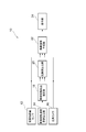
- the vehicle peripheral obstacle display device 10 includes an obstacle distance sensor 12, a vehicle moving speed / distance calculator 14, a wide-angle camera 16, and a vehicle moving trajectory estimator 18. , A risk calculation unit 20, a bird's-eye image generation unit 22, and a display unit 24.
- the vehicle surrounding obstacle display device 10 displays a bird's-eye image around the vehicle to assist the driver in driving, for example, when parking in a parking lot or the like.
- the obstacle distance sensor 12 measures the distance to obstacles existing around the vehicle.
- the obstacle distance sensor 12 includes, for example, a radar, an ultrasonic sensor, a stereo camera, and the like.
- the obstacle distance sensor 12 acquires information regarding the position of the obstacle in the three-dimensional space. Information on the height of the obstacle from the road surface is obtained by diverting not only the obstacle distance sensor 12 but also information obtained by the wide-angle camera 16 and other cameras mounted on the vehicle. Also good.
- the vehicle moving speed / distance calculation unit 14 calculates the moving speed and moving distance of the host vehicle.
- the vehicle moving speed / distance calculation unit 14 is configured by, for example, a sensor that detects the rotational speed of the axle.
- the vehicle moving speed / distance calculator 14 can calculate the moving speed and moving distance of the host vehicle from the rotational speed of the axle.
- the wide-angle camera 16 is a plurality of cameras that image obstacles around the host vehicle.
- the wide-angle camera 16 is, for example, the height of a license plate, a bumper, etc. of the host vehicle, and is installed at four locations on the front, rear, left, and right sides of the host vehicle.
- the vehicle movement trajectory estimation unit 18 estimates the future movement trajectory of the host vehicle based on the information on the movement speed and the movement distance of the host vehicle obtained by the vehicle movement speed / distance calculation unit 14. The vehicle movement trajectory estimation unit 18 estimates the probability that the vehicle will exist in the future at each position.
- the risk level calculation unit 20 calculates a risk level that is a possibility that an obstacle present around the host vehicle comes into contact with the host vehicle.
- the risk degree calculation unit 20 uses the probability that the vehicle will exist in the future at each position estimated by the vehicle movement trajectory estimation unit 18 and the future at each position estimated from information from the obstacle distance sensor 12 and the wide-angle camera 16. The degree of danger is calculated from the probability that there is an obstacle in.
- the bird's-eye image generation unit 22 converts the captured image around the host vehicle obtained by the wide-angle camera 16 into a bird's-eye image by viewpoint conversion.
- the bird's-eye image generation unit 22 performs image processing of an image displayed on the display unit 24 by a method described later.
- the display unit 24 displays the image processed by the bird's-eye image generation unit 22 to the driver of the host vehicle.
- the display unit 24 can be, for example, a monitor of a navigation system.
- the risk calculation unit 20 and the bird's-eye image generation unit 22 of the vehicle surrounding obstacle display device 10 are configured to detect obstacles near the vehicle based on information obtained by the obstacle distance sensor 12 and the wide-angle camera 16. It is determined whether or not there exists (S101). Whether or not there is an obstacle is determined by whether or not an object that may come into contact with the host vehicle is detected at a position higher than the road surface by the obstacle distance sensor 12 or by pattern recognition by the wide-angle camera 16. be able to.
- the risk level calculation unit 20 and the bird's-eye view image generation unit 22 repeat the following processes of S102 to S111 until there is no unprocessed obstacle.
- the degree-of-risk calculation unit 20 determines whether or not one detected obstacle may collide with the host vehicle (S103). When there is a possibility of collision (S103), the risk level calculation unit 20 sets the risk level of the obstacle as “high risk level” (S104). When there is no possibility of a collision (S103), the risk calculation unit 20 determines whether or not the distance between the obstacle and the host vehicle is a certain distance or less (for example, a distance of 0.5 m or less to a distance of 3 m or less). (S105).
- the risk level calculation unit 20 sets that the risk level of the obstacle is “medium risk level” (S106). When the distance does not fall below a certain distance (S105), the risk level calculation unit 20 sets the risk level of the obstacle as “low risk level” (S107).
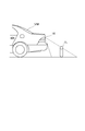
- the wide-angle camera 16 is installed at a height near the license plate of the host vehicle VM, and the obstacle O 1 has a height from the road surface.
- the bird's-eye image generation unit 22 creates a bird's-eye image by viewpoint conversion that projects each pixel of the captured image captured by the wide-angle camera 16 onto the road surface, an obstacle that is a three-dimensional object For O 1 , it appears as if it fell to the far side.
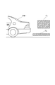
- the obstacle O 2 enters the imaging range A 0 of the wide-angle camera 16, but is not included in the range A 1 of the bird's-eye image for viewpoint conversion projected onto the road surface because the altitude from the road surface is high. That is, the obstacle O 2 is not displayed on the bird's-eye view image obtained by normal viewpoint conversion. Therefore, in the present embodiment, processing is performed as follows.
- the obstacle present in the air includes not only an obstacle that is not in contact with the ground but also an obstacle in which the portion closest to the host vehicle VM is in the air (high position). It is.
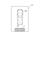
- Bird's-eye image generating unit 22 whether or not such an obstacle O 2 is equal to or higher than a predetermined height from the road surface, i.e., outside the scope A 1 of the bird's-eye view image of the view transform such obstacle O 2 is projected on the road surface It is determined whether it is too high (S108). If the altitude of the obstacle O 2 or the like is equal to or higher than the predetermined height (S108), the bird's-eye image generation unit 22 displays the bird's-eye image 101 of the display image 100 of the display unit 24 as shown in FIG. The image of the obstacle O 2 or the like captured by the wide-angle camera 16 is displayed together with the ejection 103 or the like without being converted into a bird's-eye view image (S109).
- the bird's-eye image generation unit 22 projects a captured image showing the obstacle O 2 or the like on the road surface.
- a bird's-eye image for viewpoint conversion is generated and displayed on the bird's-eye image 101.
- the bird's-eye image generation unit 22 corresponds to the position of the obstacle O 2 or the like on the bird's-eye image 101.
- the line 102 is displayed at the location (S110).
- the jet 103 is applied to the line 102. This makes it easier for the driver to know that the line 102 corresponds to the obstacle O 2 or the like. In addition, the driver can easily grasp the distance to the obstacle O 2 or the like. This makes it easier for the driver to perform operations such as width adjustment.
- the line 102 and the eruption 103 are displayed in a color or highlighted display according to the danger level of the obstacle (S110).
- the bird's-eye image generation unit 22 performs the above-described image processing with priority in descending order of the risk level. If there is no capacity for the arithmetic processing, the image processing is performed in ascending order of the risk level. Shall be omitted.
- the bird's-eye view image generation unit 22 displays only the bird's-eye view image of viewpoint conversion for projecting the captured image of the wide-angle camera 16 on the road surface on the display unit 24. (S112).
- the wide-angle camera 16 that captures an object around the host vehicle VM, the obstacle distance sensor 12 that measures the distance from the host vehicle VM to the object, and the image of the object captured by the wide-angle camera 16 are displayed on the host vehicle VM.
- the vehicle peripheral obstacle display device 10 including the bird's-eye image generation unit 22 and the display unit 24 that are displayed as surrounding bird's-eye images the bird's-eye image creation unit 22 and the display unit 24 are distances measured by the obstacle distance sensor 12.
- the object image captured by the wide-angle camera 16 is incorporated and displayed at a position in the bird's-eye view image 101 around the host vehicle VM corresponding to.
- the position of the object on the bird's-eye view image 101 does not match the position of the object based on the measurement result of the obstacle distance sensor 12, the position of the object can be correctly displayed. For this reason, the driver can easily grasp the position of the object around the host vehicle VM.
- the bird's-eye image creation unit 22 creates the bird's-eye image 101 around the host vehicle VM based on the height of the road surface. Since the bird's-eye image creation unit 22 incorporates and displays the object image captured by the wide-angle camera 16 at a position in the bird's-eye image 101 around the host vehicle VM corresponding to the distance measured by the obstacle distance sensor 12. Even if the bird's-eye view image 101 around the VM is created based on the height of the road surface, it is possible to easily display objects with different heights such as white lines on the road surface and objects at a high position from the road surface.
- the risk level calculation unit 20 determines whether one detected obstacle may collide with the host vehicle, and the line 102 and the jet 103 in the bird's-eye view image 101 are determined. Is displayed with a color or highlighting according to the danger level of the obstacle indicating the possibility of a collision with the host vehicle, so that the driver can easily grasp the danger level of the obstacle.
- the bird's-eye image creation unit 22 preferentially incorporates and displays in the bird's-eye image 101 around the host vehicle VM an image of an object that has a high possibility of contact with the host vehicle VM. For this reason, the calculation load of the apparatus can be efficiently reduced.
- the bird's-eye image creation unit 22 associates the object captured by the wide-angle camera 16 with the position in the bird's-eye image 101 around the host vehicle VM corresponding to the distance measured by the obstacle distance sensor 12.
- the image is displayed by jetting together with the bird's-eye view image 101 around the host vehicle VM without converting the image into a bird's-eye view image. For this reason, even when it is difficult to grasp the position of the object from the bird's-eye view image of the object, the driver can easily grasp the presence of the object and the position of the object.
- FIG. 7 the processing of S201 to S207 similar to S101 to S107 of the first embodiment is performed.
- FIG. 8 a situation is assumed in which obstacles O 3 and O 4 having different heights exist behind the host vehicle VM.
- a bird's-eye view image of viewpoint conversion for projecting an image captured by the wide-angle camera 16 on the road surface is created for the obstacle O 3 existing in the air, as described above, the obstacle O 3 is actually located in the bird's-eye view image. Rather than the vehicle VM. Therefore, it is also conceivable to create a bird's-eye view image for viewpoint conversion in which the image captured by the wide-angle camera 16 is projected onto a plane having a height of the obstacle O 3 .
- the obstacle O 4 such as a white line on the road surface is similarly obstructed as shown in FIG. since the viewpoint conversion based on the height of the object O 3, and are displayed near the host vehicle VM than the actual position obstacle O 4 blocks of the road surface or the like of the white line and the road is in the bird's-eye image.
- FIG. 10 a situation is assumed in which an obstacle O 3 existing in the air such as a truck bed is present behind the host vehicle VM.
- the obstacle O 3 enters the imaging range A 0 of the wide-angle camera 16 but is not included in the range A 1 of the bird's-eye view image for viewpoint conversion projected onto the road surface because the altitude from the road surface is high. That is, the obstacle O 3 is not displayed on the bird's-eye view image obtained by normal viewpoint conversion.
- processing is performed as follows.
- the bird's-eye image generation unit 22 determines whether the obstacle O 3 or the like is equal to or higher than a predetermined height from the road surface (S208). If the obstacle O 3 or the like is equal to or higher than a predetermined height from the road surface (S208), the bird's-eye image generation unit 22 enters the range A 1 of the bird's-eye image for viewpoint conversion projected on the road surface by the obstacle O 3 or the like. It is determined whether it is so high that it is not included (S209). If the obstacle O 3 or the like is so high that it is not included in the range A 1 of the viewpoint conversion bird's-eye image projected onto the road surface (S209), the bird's-eye image generation unit 22 determines the obstacle O 3 and the like for the host vehicle. Using the height of the portion closest to the VM as the projection plane P, a bird's-eye view image for viewpoint conversion projected onto the projection plane P is created (S210).
- the bird's-eye image generation unit 22 converts a bird's-eye image such as an obstacle O 3 on the projection plane P to a position corresponding to the position of the obstacle O 3 or the like on the bird's-eye image 101.
- a pasting process is performed while deforming such as cutting into the shape of the line 102 (S211).
- the obstacle O 5 exists in the air, but a situation that is also included in the range A 1 of the bird's-eye view image of the viewpoint conversion projected onto the road surface is assumed. If the height is such that the obstacle O 5 or the like is included in the range A 1 of the bird's-eye view image of the viewpoint conversion projected onto the road surface (S209), the bird's-eye image generation unit 22 as shown in FIG.
- the viewpoint conversion bird's-eye image 101 with the road surface as the projection plane is created both around the host vehicle VM and the obstacle O 5, and the bird's-eye image such as the obstacle O 5 is displayed on the bird's-eye image 101. Processing for enlarging, reducing, deforming, etc.
- This enlargement process or the like may be a process for changing the aspect ratio of the bird's-eye view image such as the obstacle O 5 or a process for performing rotation or the like.
- the following processes in S213 to S215 are performed in the same manner as in the first embodiment.
- the bird's-eye image creation unit 22 creates a bird's-eye view image of an object based on the height of the object from the image of the object captured by the wide-angle camera 16, and uses the created bird's-eye view image around the host vehicle VM.
- the bird's-eye view image 101 are incorporated into the bird's-eye view image 101 and displayed. For this reason, objects with different heights around the host vehicle VM can be displayed as if actually viewed from above the host vehicle VM.
- the bird's-eye image creation unit 22 creates the bird's-eye view image 101 around the host vehicle VM based on the height of the road surface, and the bird's-eye view around the host vehicle created based on the height of the road surface. While performing any one of processing of moving, transforming, enlarging and reducing the bird's-eye view image of the object created based on the height of the object to the position corresponding to the distance measured by the obstacle distance sensor 12 in the image 101, Incorporate and display.
- the vehicle surrounding obstacle display device and the vehicle surrounding obstacle display method of the present invention it is easier for the driver to grasp the position of an object around the host vehicle.
Landscapes
- Engineering & Computer Science (AREA)
- Multimedia (AREA)
- Physics & Mathematics (AREA)
- General Physics & Mathematics (AREA)
- Mechanical Engineering (AREA)
- Closed-Circuit Television Systems (AREA)
- Image Processing (AREA)
Abstract
A vehicle periphery obstacle display device (10) comprises: a wide-angle camera (16) which captures an image of an object in the periphery of a host vehicle (VM); an obstacle range sensor (12) which measures the distance from the host vehicle (VM) to the object; and a bird's-eye image generation unit (22) and a display unit (24) which display the image of the object which the wide-angle camera (16) has captured as a bird's-eye image of the periphery of the host vehicle (VM). The display unit (24) incorporates and displays the image of the object which the wide-angle camera (16) has captured in the location within a bird's-eye image (101) of the periphery of the host vehicle (VM) which corresponds to the distance which the obstacle range sensor (12) has measured. It is thus possible to properly display the location of the object even when the location of the object in the bird's-eye image (101) does not match the location of the object based on the result of the measurement of the obstacle range sensor (12). It is thus easy for a driver to ascertain the location of an object in the periphery of the host vehicle (VM).
Description
本発明は、車両用周辺障害物表示装置及び車両用周辺障害物表示方法に関し、特に撮像した自車両周囲の物体の画像を自車両周囲の鳥瞰画像として表示する車両用周辺障害物表示装置及び車両用周辺障害物表示方法に関する。
The present invention relates to a vehicle peripheral obstacle display device and a vehicle peripheral obstacle display method, and more particularly to a vehicle peripheral obstacle display device and a vehicle that display a captured image of an object around the host vehicle as a bird's-eye image around the host vehicle. The present invention relates to a peripheral obstacle display method.
近年、駐車場等で駐車を行なう際に、車両のドライバーの運転を支援するために、例えば、4つの広角カメラを用いて撮像した自車両周囲の物体の画像の視点変換を行い、自車両周囲の鳥瞰画像として表示する装置が提案されている。例えば、特許文献1には、ドライバーに対して、車両と障害物との位置関係を判り易く伝達するための装置が開示されている。特許文献1の装置では、表示器と、カメラと、カメラにより撮像される車両周辺の画像を鳥瞰図に変換するとともに、この変換される鳥瞰図を自車位置マークに重畳して表示器に表示させる処理ユニットと、車両周辺の障害物までの距離を測定するための距離測定センサとを備えている。処理ユニットは、距離測定センサにより測定される距離に基づき、車両周辺の障害物の位置を特定するとともに、センサ位置マーク及び障害物の検出点マークを自車位置マークに重畳し、かつセンサ位置マーク及び障害物の検出位置マークをラインで強調して表示器にて表示させる。
In recent years, when parking in a parking lot or the like, in order to assist the driving of the vehicle driver, for example, the viewpoint conversion of the image of the object around the own vehicle taken using four wide-angle cameras is performed, and the surroundings of the own vehicle Have been proposed for displaying a bird's-eye view image. For example, Patent Literature 1 discloses an apparatus for easily transmitting a positional relationship between a vehicle and an obstacle to a driver. In the device of Patent Document 1, a display, a camera, and an image around the vehicle imaged by the camera are converted into a bird's-eye view, and the converted bird's-eye view is superimposed on the vehicle position mark and displayed on the display. A unit and a distance measuring sensor for measuring a distance to an obstacle around the vehicle are provided. The processing unit identifies the position of the obstacle around the vehicle based on the distance measured by the distance measuring sensor, superimposes the sensor position mark and the obstacle detection point mark on the own vehicle position mark, and the sensor position mark. The obstacle detection position mark is highlighted with a line and displayed on the display.
しかしながら、上記技術では、対象物が路面から高さを有する立体物であることを考慮していない。そのため、対象物がトラックの荷台等の空中に存在する障害物である場合、鳥瞰画像と対象物を示すラインとが一致しない場合がある。この場合、ドライバーはラインが何の障害物を示しているのか判らず、ドライバーが障害物との距離を把握し難いという欠点がある。
However, the above technique does not consider that the object is a three-dimensional object having a height from the road surface. Therefore, when the target object is an obstacle existing in the air such as a truck bed, the bird's-eye view image may not match the line indicating the target object. In this case, the driver does not know what obstacle the line indicates, and there is a drawback that it is difficult for the driver to grasp the distance to the obstacle.
すなわち、鳥瞰画像は、車両の場合、車両より上の高さにカメラを設置することができないため、車両後部のナンバープレート付近に設置したカメラ等で撮影した撮影画像の各画素を路面に投影するような視点変換を行なうことで実現されている。そのため、鳥瞰画像は、路面上の白線等の路面上の物に対しては、物体との距離を正確に表現することができるが、立体物に対しては遠方側に倒れたように表示される。そのため、鳥瞰画像を視たドライバーは、物体との距離が判り難いという問題がある。
That is, in a bird's-eye view image, in the case of a vehicle, a camera cannot be installed at a height above the vehicle, so each pixel of a photographed image taken with a camera or the like installed near the license plate at the rear of the vehicle is projected onto the road surface. This is realized by performing such viewpoint conversion. Therefore, the bird's-eye view image can accurately represent the distance to the object for objects on the road surface such as white lines on the road surface, but is displayed as if it fell to the far side for a three-dimensional object. The Therefore, there is a problem that the driver who viewed the bird's-eye view image cannot easily understand the distance to the object.
本発明は、このような事情を考慮してなされたものであり、その目的は、ドライバーが自車両周囲の物体の位置をより把握し易い車両用周辺障害物表示装置及び車両用周辺障害物表示方法を提供することにある。
The present invention has been made in view of such circumstances, and an object of the present invention is to provide a vehicle peripheral obstacle display device and a vehicle peripheral obstacle display that make it easier for the driver to grasp the position of an object around the host vehicle. It is to provide a method.
本発明は、自車両周囲の物体を撮像する撮像ユニットと、自車両から物体までの距離を取得する距離取得ユニットと、撮像ユニットが撮像した物体の画像を自車両周囲の鳥瞰画像として表示する表示ユニットとを備え、表示ユニットは、距離取得ユニットが取得した距離に対応した自車両周囲の鳥瞰画像中の位置に、撮像ユニットが撮像した物体の画像を組み入れて表示する車両用周辺障害物表示装置である。
The present invention provides an imaging unit that captures an object around the host vehicle, a distance acquisition unit that acquires a distance from the host vehicle to the object, and a display that displays an image of the object captured by the imaging unit as a bird's-eye view around the host vehicle. A vehicle surrounding obstacle display device that displays an image of an object captured by the imaging unit at a position in a bird's-eye view around the host vehicle corresponding to the distance acquired by the distance acquisition unit. It is.
この構成によれば、自車両周囲の物体を撮像する撮像ユニットと、自車両から物体までの距離を取得する距離取得ユニットと、撮像ユニットが撮像した物体の画像を自車両周囲の鳥瞰画像として表示する表示ユニットとを備えた車両用周辺障害物表示装置において、表示ユニットは、距離取得ユニットが取得した距離に対応した自車両周囲の鳥瞰画像中の位置に、撮像ユニットが撮像した物体の画像を組み入れて表示する。このため、鳥瞰画像上の物体の位置と距離取得ユニットの取得結果に基づく物体の位置とが一致しない場合においても、物体の位置を正しく表示することができる。このため、ドライバーが自車両周囲の物体の位置をより把握し易い。
According to this configuration, an imaging unit that captures an object around the host vehicle, a distance acquisition unit that acquires the distance from the host vehicle to the object, and an image of the object captured by the imaging unit is displayed as a bird's-eye view around the host vehicle. In the vehicle peripheral obstacle display device including the display unit, the display unit displays the image of the object captured by the imaging unit at a position in the bird's-eye image around the host vehicle corresponding to the distance acquired by the distance acquisition unit. Incorporate and display. For this reason, even when the position of the object on the bird's-eye view image and the position of the object based on the acquisition result of the distance acquisition unit do not match, the position of the object can be correctly displayed. For this reason, it is easier for the driver to grasp the position of the object around the host vehicle.
この場合、表示ユニットは、撮像ユニットが撮像した物体の画像から物体の高さに基づいて物体の鳥瞰画像を作成し、作成した物体の鳥瞰画像を自車両周囲の鳥瞰画像中に組み入れて表示するものとできる。
In this case, the display unit creates a bird's-eye image of the object based on the height of the object from the image of the object imaged by the imaging unit, and displays the created bird's-eye image of the created object in the bird's-eye image around the host vehicle. I can do it.
この構成によれば、撮像ユニットが撮像した物体の画像から物体の高さに基づいて物体の鳥瞰画像を作成し、作成した物体の鳥瞰画像を自車両周囲の鳥瞰画像中に組み入れて表示する。このため、自車両周囲の高さが異なる物体についても、実際に自車両の上方から鳥瞰したように表示することができる。
According to this configuration, the bird's-eye image of the object is created from the image of the object captured by the imaging unit based on the height of the object, and the bird's-eye image of the created object is incorporated into the bird's-eye image around the vehicle. For this reason, objects having different heights around the host vehicle can be displayed as if actually viewed from above the host vehicle.
また、表示ユニットは、自車両周囲の鳥瞰画像を路面の高さを基準として作成するものとできる。
In addition, the display unit can create a bird's-eye view around the host vehicle based on the height of the road surface.
この構成によれば、表示ユニットは、自車両周囲の鳥瞰画像を路面の高さを基準として作成する。本発明では、距離取得ユニットが取得した距離に対応した自車両周囲の鳥瞰画像中の位置に、撮像ユニットが撮像した物体の画像を組み入れて表示するため、自車両周囲の鳥瞰画像を路面の高さを基準として作成したとしても、路面上の白線や、路面から高い位置にある物体のように高さの異なる物体を判り易く表示することができる。
According to this configuration, the display unit creates a bird's-eye view around the host vehicle based on the height of the road surface. In the present invention, the image of the object imaged by the imaging unit is incorporated and displayed at a position in the bird's-eye image around the host vehicle corresponding to the distance acquired by the distance acquisition unit. Even if it is created based on the height, it is possible to easily display an object having a different height such as a white line on the road surface or an object at a high position from the road surface.
また、表示ユニットは、自車両周囲の鳥瞰画像を路面の高さを基準として作成し、路面の高さを基準として作成された自車両周囲の鳥瞰画像中の距離取得ユニットが取得した距離に対応した位置に、物体の高さに基づいて作成された物体の鳥瞰画像を移動、変形、拡大及び縮小のいずれかの処理を施しつつ、組み入れて表示するものとできる。
In addition, the display unit creates a bird's-eye view around the vehicle based on the height of the road surface, and corresponds to the distance acquired by the distance acquisition unit in the bird's-eye image around the vehicle created based on the road surface height. The bird's-eye view image of the object created based on the height of the object can be incorporated and displayed at any of the positions while performing any of the processes of movement, deformation, enlargement, and reduction.
この構成によれば、表示ユニットは、自車両周囲の鳥瞰画像を路面の高さを基準として作成し、路面の高さを基準として作成された自車両周囲の鳥瞰画像中の距離取得ユニットが取得した距離に対応した位置に、物体の高さに基づいて作成された物体の鳥瞰画像を移動、変形、拡大及び縮小のいずれかの処理を施しつつ、組み入れて表示する。このため、自車両周囲の鳥瞰画像と障害物の鳥瞰画像とで基準とする投影面の高さが異なっていても、同じ鳥瞰画像だけで、障害物の存在とその位置とを正確にドライバーに表示することが可能となる。
According to this configuration, the display unit creates a bird's-eye view around the host vehicle based on the road surface height, and the distance acquisition unit in the bird's-eye image around the host vehicle created based on the road surface height acquires the display unit. The bird's-eye view image of the object created based on the height of the object is incorporated and displayed at any position corresponding to the distance while performing any of the processes of movement, deformation, enlargement, and reduction. For this reason, even if the bird's-eye view image around the vehicle and the bird's-eye view image of the obstacle are different in height from the reference projection plane, only the same bird's-eye view image can be used to accurately detect the presence and position of the obstacle. It is possible to display.
また、車両と物体との接触可能性を算出する危険度算出ユニットを備えるものとできる。
Also, a risk calculation unit for calculating the possibility of contact between the vehicle and the object can be provided.
この構成によれば、危険度算出ユニットが車両と物体との接触可能性を算出するため、例えば、算出した接触可能性に応じて物体を表示ユニットに表示することが可能となる。
According to this configuration, since the risk calculation unit calculates the possibility of contact between the vehicle and the object, for example, the object can be displayed on the display unit according to the calculated contact possibility.
また、表示ユニットは、自車両との接触の可能性が高い物体の画像ほど優先的に自車両周囲の鳥瞰画像中に組み入れて表示するものとできる。
Also, the display unit can preferentially incorporate and display an image of an object having a high possibility of contact with the host vehicle in a bird's-eye image around the host vehicle.
この構成によれば、表示ユニットは、自車両との接触の可能性が高い物体の画像ほど優先的に自車両周囲の鳥瞰画像中に組み入れて表示する。このため、装置の演算負荷を効率よく低減することができる。
According to this configuration, the display unit preferentially incorporates and displays an image of an object having a high possibility of contact with the host vehicle in the bird's-eye view around the host vehicle. For this reason, the calculation load of the apparatus can be efficiently reduced.
また、表示ユニットは、距離取得ユニットが取得した距離に対応した自車両周囲の鳥瞰画像中の位置に対応付けて、撮像ユニットが撮像した物体の画像を鳥瞰画像に変換することなく、自車両周囲の鳥瞰画像と共に表示するものとできる。
In addition, the display unit associates with the position in the bird's-eye image around the vehicle corresponding to the distance acquired by the distance acquisition unit, and converts the object image captured by the imaging unit into the bird's-eye image without converting the image of the object into the bird's-eye image. It can be displayed together with a bird's-eye view image.
この構成によれば、表示ユニットは、距離取得ユニットが取得した距離に対応した自車両周囲の鳥瞰画像中の位置に対応付けて、撮像ユニットが撮像した物体の画像を鳥瞰画像に変換することなく、自車両周囲の鳥瞰画像と共に表示する。このため、物体の鳥瞰画像から物体の位置が把握し難い場合でも、ドライバーが物体の存在と物体の位置とを把握し易い。
According to this configuration, the display unit associates the position of the object captured by the imaging unit with the position in the bird's-eye image around the host vehicle corresponding to the distance acquired by the distance acquisition unit without converting the image of the object to the bird's-eye image. It is displayed together with a bird's-eye view around the vehicle. For this reason, even when it is difficult to grasp the position of the object from the bird's-eye view image of the object, the driver can easily grasp the presence of the object and the position of the object.
また、本発明は、撮像された自車両周囲の画像を自車両周囲の鳥瞰画像として表示し、鳥瞰画像における自車両から自車両周囲の物体までの距離に対応する位置に、前記物体の画像を組み入れる車両用周辺障害物表示方法である。
The present invention also displays a captured image around the host vehicle as a bird's-eye image around the host vehicle, and displays the image of the object at a position corresponding to the distance from the host vehicle to the object around the host vehicle in the bird's-eye view image. This is a vehicle peripheral obstacle display method to be incorporated.
なお、本発明においては、鳥瞰画像の表示のタイミングと、自車両周囲の物体の画像を組み入れた後の鳥瞰画像の表示タイミングとは、時間差があってもなくてもどちらでも良い。
In the present invention, the display timing of the bird's-eye view image and the display timing of the bird's-eye view image after incorporating the image of the object around the host vehicle may or may not have a time difference.
本発明の車両用周辺障害物表示装置及び車両用周辺障害物表示方法によれば、ドライバーが自車両周囲の物体の位置をより把握し易い。
According to the vehicle surrounding obstacle display device and the vehicle surrounding obstacle display method of the present invention, it is easier for the driver to grasp the position of an object around the host vehicle.
以下、図面を参照して本発明の実施形態に係る車両用周辺障害物表示装置について説明する。図1に示すように、本発明の第1実施形態の車両用周辺障害物表示装置10は、障害物距離センサ12、車両移動速度・距離算出部14、広角カメラ16、車両移動軌道推定部18、危険度算出部20、鳥瞰画像生成部22、及び表示部24を備えている。本実施形態の車両用周辺障害物表示装置10は、例えば、駐車場等で駐車を行なう際に、ドライバーに車両周辺の鳥瞰画像を表示して、ドライバーの運転を支援する。
Hereinafter, a vehicle peripheral obstacle display device according to an embodiment of the present invention will be described with reference to the drawings. As shown in FIG. 1, the vehicle peripheral obstacle display device 10 according to the first embodiment of the present invention includes an obstacle distance sensor 12, a vehicle moving speed / distance calculator 14, a wide-angle camera 16, and a vehicle moving trajectory estimator 18. , A risk calculation unit 20, a bird's-eye image generation unit 22, and a display unit 24. The vehicle surrounding obstacle display device 10 according to the present embodiment displays a bird's-eye image around the vehicle to assist the driver in driving, for example, when parking in a parking lot or the like.
障害物距離センサ12は、車両周辺に存在する障害物との距離を計測する。障害物距離センサ12は、例えば、レーダ、超音波センサ、ステレオカメラ等から構成されている。障害物距離センサ12は、障害物の3次元空間上の位置に関する情報を取得する。なお、障害物の路面からの高さに関する情報は、障害物距離センサ12だけではなく、広角カメラ16や、その他の車両に搭載されたカメラにより得られた情報を流用することにより、取得しても良い。
The obstacle distance sensor 12 measures the distance to obstacles existing around the vehicle. The obstacle distance sensor 12 includes, for example, a radar, an ultrasonic sensor, a stereo camera, and the like. The obstacle distance sensor 12 acquires information regarding the position of the obstacle in the three-dimensional space. Information on the height of the obstacle from the road surface is obtained by diverting not only the obstacle distance sensor 12 but also information obtained by the wide-angle camera 16 and other cameras mounted on the vehicle. Also good.
車両移動速度・距離算出部14は、自車両の移動速度及び移動距離を算出する。車両移動速度・距離算出部14は、例えば、車軸の回転速度を検出するセンサにより構成される。車両移動速度・距離算出部14は、車軸の回転速度から自車両の移動速度及び移動距離を算出することができる。
The vehicle moving speed / distance calculation unit 14 calculates the moving speed and moving distance of the host vehicle. The vehicle moving speed / distance calculation unit 14 is configured by, for example, a sensor that detects the rotational speed of the axle. The vehicle moving speed / distance calculator 14 can calculate the moving speed and moving distance of the host vehicle from the rotational speed of the axle.
広角カメラ16は、自車両周囲の障害物を撮像する複数台のカメラである。広角カメラ16は、例えば、自車両のナンバープレート、バンパー等の高さであって、自車両の前後左右の4箇所に設置される。
The wide-angle camera 16 is a plurality of cameras that image obstacles around the host vehicle. The wide-angle camera 16 is, for example, the height of a license plate, a bumper, etc. of the host vehicle, and is installed at four locations on the front, rear, left, and right sides of the host vehicle.
車両移動軌道推定部18は、車両移動速度・距離算出部14により得られた自車両の移動速度及び移動距離に関する情報に基づいて、自車両の将来の移動軌道を推定する。車両移動軌道推定部18は、各位置において将来に自車両が存在する確率を推定する。
The vehicle movement trajectory estimation unit 18 estimates the future movement trajectory of the host vehicle based on the information on the movement speed and the movement distance of the host vehicle obtained by the vehicle movement speed / distance calculation unit 14. The vehicle movement trajectory estimation unit 18 estimates the probability that the vehicle will exist in the future at each position.
危険度算出部20は、自車両周囲に存在する障害物と自車両とが接触する可能性である危険度を算出する。危険度算出部20は、車両移動軌道推定部18により推定された各位置において将来に自車両が存在する確率と、障害物距離センサ12及び広角カメラ16からの情報によって推定される各位置において将来に障害物が存在する確率とから、危険度を算出する。
The risk level calculation unit 20 calculates a risk level that is a possibility that an obstacle present around the host vehicle comes into contact with the host vehicle. The risk degree calculation unit 20 uses the probability that the vehicle will exist in the future at each position estimated by the vehicle movement trajectory estimation unit 18 and the future at each position estimated from information from the obstacle distance sensor 12 and the wide-angle camera 16. The degree of danger is calculated from the probability that there is an obstacle in.
鳥瞰画像生成部22は、広角カメラ16により得られた自車両周囲の撮像画像を視点変換により鳥瞰画像とする。また、鳥瞰画像生成部22は、後述する手法により、表示部24に表示する画像の画像処理を行なう。
The bird's-eye image generation unit 22 converts the captured image around the host vehicle obtained by the wide-angle camera 16 into a bird's-eye image by viewpoint conversion. The bird's-eye image generation unit 22 performs image processing of an image displayed on the display unit 24 by a method described later.
表示部24は、鳥瞰画像生成部22により画像処理がなされた画像を自車両のドライバーに表示する。表示部24は、例えば、ナビゲーションシステムのモニターとすることができる。
The display unit 24 displays the image processed by the bird's-eye image generation unit 22 to the driver of the host vehicle. The display unit 24 can be, for example, a monitor of a navigation system.
以下、本実施形態の車両用周辺障害物表示装置10の動作について説明する。図2に示すように、車両用周辺障害物表示装置10の危険度算出部20及び鳥瞰画像生成部22は、障害物距離センサ12及び広角カメラ16により得られた情報から、車両近傍に障害物が存在するか否かを判定する(S101)。障害物が存在するか否かの判定は、障害物距離センサ12によって路面より高い位置に自車両と接触する可能性がある物体が検知されているか否かや、広角カメラ16によるパターン認識により行なうことができる。
Hereinafter, the operation of the vehicle peripheral obstacle display device 10 of the present embodiment will be described. As shown in FIG. 2, the risk calculation unit 20 and the bird's-eye image generation unit 22 of the vehicle surrounding obstacle display device 10 are configured to detect obstacles near the vehicle based on information obtained by the obstacle distance sensor 12 and the wide-angle camera 16. It is determined whether or not there exists (S101). Whether or not there is an obstacle is determined by whether or not an object that may come into contact with the host vehicle is detected at a position higher than the road surface by the obstacle distance sensor 12 or by pattern recognition by the wide-angle camera 16. be able to.
車両近傍に障害物が存在する場合は(S101)、危険度算出部20及び鳥瞰画像生成部22は、未処理の障害物が無くなるまで、以下のS102~S111の処理を繰り返す。危険度算出部20は、検出された一つの障害物が自車両との衝突の可能性があるか否かを判定する(S103)。衝突の可能性があるときは(S103)、危険度算出部20は、当該障害物の危険度は「危険度大」であると設定する(S104)。衝突の可能性が無いときは(S103)、危険度算出部20は、当該障害物と自車両との距離が一定の距離以下(例えば、距離0・5m以下~距離3m以下)となるか否かについて判定する(S105)。距離が一定の距離以下となるときは(S105)、危険度算出部20は、当該障害物の危険度は「危険度中」であると設定する(S106)。距離が一定の距離以下とはならないときは(S105)、危険度算出部20は、当該障害物の危険度は「危険度小」であると設定する(S107)。
If there is an obstacle in the vicinity of the vehicle (S101), the risk level calculation unit 20 and the bird's-eye view image generation unit 22 repeat the following processes of S102 to S111 until there is no unprocessed obstacle. The degree-of-risk calculation unit 20 determines whether or not one detected obstacle may collide with the host vehicle (S103). When there is a possibility of collision (S103), the risk level calculation unit 20 sets the risk level of the obstacle as “high risk level” (S104). When there is no possibility of a collision (S103), the risk calculation unit 20 determines whether or not the distance between the obstacle and the host vehicle is a certain distance or less (for example, a distance of 0.5 m or less to a distance of 3 m or less). (S105). When the distance is equal to or less than a certain distance (S105), the risk level calculation unit 20 sets that the risk level of the obstacle is “medium risk level” (S106). When the distance does not fall below a certain distance (S105), the risk level calculation unit 20 sets the risk level of the obstacle as “low risk level” (S107).
ここで、図3に示すように、広角カメラ16は自車両VMのナンバープレート付近の高さに設置されており、障害物O1が路面から高さを有している状況を想定する。この場合、図4に示すように、鳥瞰画像生成部22が、広角カメラ16で撮影した撮影画像の各画素を路面に投影するような視点変換により鳥瞰画像を作成すると、立体物である障害物O1に対しては遠方側に倒れたように表示される。
Here, as shown in FIG. 3, it is assumed that the wide-angle camera 16 is installed at a height near the license plate of the host vehicle VM, and the obstacle O 1 has a height from the road surface. In this case, as shown in FIG. 4, when the bird's-eye image generation unit 22 creates a bird's-eye image by viewpoint conversion that projects each pixel of the captured image captured by the wide-angle camera 16 onto the road surface, an obstacle that is a three-dimensional object For O 1 , it appears as if it fell to the far side.
また、図5に示すように、トラックの荷台のような空中に存在する障害物O2が自車両VMの後方に存在している状況を想定する。この場合、障害物O2は、広角カメラ16の撮像範囲A0には入るが、路面からの高度が高いために路面に投影する視点変換の鳥瞰画像の範囲A1には含まれない。すなわち、通常の視点変換による鳥瞰画像には、障害物O2は表示されないことになる。そこで、本実施形態では以下のように処理する。なお、本発明の実施形態において、空中に存在する障害物とは、地面に接していない障害物だけではなく、障害物における自車両VMに最も近い部分が空中(高位置)にあるものも含まれる。
Further, as shown in FIG. 5, a situation is assumed in which an obstacle O 2 existing in the air such as a truck bed is present behind the host vehicle VM. In this case, the obstacle O 2 enters the imaging range A 0 of the wide-angle camera 16, but is not included in the range A 1 of the bird's-eye image for viewpoint conversion projected onto the road surface because the altitude from the road surface is high. That is, the obstacle O 2 is not displayed on the bird's-eye view image obtained by normal viewpoint conversion. Therefore, in the present embodiment, processing is performed as follows. In the embodiment of the present invention, the obstacle present in the air includes not only an obstacle that is not in contact with the ground but also an obstacle in which the portion closest to the host vehicle VM is in the air (high position). It is.
鳥瞰画像生成部22は、障害物O2等が路面から所定の高さ以上であるか否か、すなわち、障害物O2等が路面に投影する視点変換の鳥瞰画像の範囲A1には含まれないほど高いか否かを判定する(S108)。もし、障害物O2等の高度が所定の高さ以上であるときは(S108)、鳥瞰画像生成部22は、図6に示すように、表示部24の表示画像100の鳥瞰画像101に、広角カメラ16が撮像した障害物O2等の画像を鳥瞰画像に変換することなく、噴出し103等によって併せて表示する(S109)。
Bird's-eye image generating unit 22, whether or not such an obstacle O 2 is equal to or higher than a predetermined height from the road surface, i.e., outside the scope A 1 of the bird's-eye view image of the view transform such obstacle O 2 is projected on the road surface It is determined whether it is too high (S108). If the altitude of the obstacle O 2 or the like is equal to or higher than the predetermined height (S108), the bird's-eye image generation unit 22 displays the bird's-eye image 101 of the display image 100 of the display unit 24 as shown in FIG. The image of the obstacle O 2 or the like captured by the wide-angle camera 16 is displayed together with the ejection 103 or the like without being converted into a bird's-eye view image (S109).
また、障害物O2等が路面から所定の高さ以上であるか否かに関わらず(S108)、鳥瞰画像生成部22は、障害物O2等が写っている撮像画像を路面に投影する視点変換の鳥瞰画像を生成し、鳥瞰画像101上に表示する。また、障害物O2等が路面から所定の高さ以上であるか否かに関わらず(S108)、鳥瞰画像生成部22は、鳥瞰画像101上における当該障害物O2等の位置に相当する箇所にライン102を表示する(S110)。上記の噴出し103はライン102に対して付けられる。これにより、ライン102が障害物O2等に相当することをドライバーが把握し易くなる。また、ドライバーは障害物O2等に対しての距離を把握し易くなる。そのため、ドライバーが幅寄せ等の操作をし易くなる。
Regardless of whether or not the obstacle O 2 or the like is above a predetermined height from the road surface (S108), the bird's-eye image generation unit 22 projects a captured image showing the obstacle O 2 or the like on the road surface. A bird's-eye image for viewpoint conversion is generated and displayed on the bird's-eye image 101. Regardless of whether or not the obstacle O 2 or the like is above a predetermined height from the road surface (S108), the bird's-eye image generation unit 22 corresponds to the position of the obstacle O 2 or the like on the bird's-eye image 101. The line 102 is displayed at the location (S110). The jet 103 is applied to the line 102. This makes it easier for the driver to know that the line 102 corresponds to the obstacle O 2 or the like. In addition, the driver can easily grasp the distance to the obstacle O 2 or the like. This makes it easier for the driver to perform operations such as width adjustment.
ライン102及び噴出し103は、障害物の危険度に応じた色や強調表示により表示される(S110)。また、本実施形態では、鳥瞰画像生成部22は、危険度が大きい順に優先的に上記の画像処理を行い、もし、演算処理の能力に余裕がないときは、危険度の小さい順に画像処理を省略するものとする。なお、自車両VMの近傍に障害物が存在しないときは(S101)、鳥瞰画像生成部22は、広角カメラ16の撮像画像を路面に投影する視点変換の鳥瞰画像のみを表示部24に表示する(S112)。
The line 102 and the eruption 103 are displayed in a color or highlighted display according to the danger level of the obstacle (S110). In the present embodiment, the bird's-eye image generation unit 22 performs the above-described image processing with priority in descending order of the risk level. If there is no capacity for the arithmetic processing, the image processing is performed in ascending order of the risk level. Shall be omitted. When there is no obstacle in the vicinity of the host vehicle VM (S101), the bird's-eye view image generation unit 22 displays only the bird's-eye view image of viewpoint conversion for projecting the captured image of the wide-angle camera 16 on the road surface on the display unit 24. (S112).
本実施形態では、自車両VM周囲の物体を撮像する広角カメラ16と、自車両VMから物体までの距離を計測する障害物距離センサ12と、広角カメラ16が撮像した物体の画像を自車両VM周囲の鳥瞰画像として表示する鳥瞰画像生成部22及び表示部24とを備えた車両用周辺障害物表示装置10において、鳥瞰画像作成部22及び表示部24は、障害物距離センサ12が計測した距離に対応した自車両VM周囲の鳥瞰画像101中の位置に、広角カメラ16が撮像した物体の画像を組み入れて表示する。このため、鳥瞰画像101上の物体の位置と障害物距離センサ12の計測結果に基づく物体の位置とが一致しない場合においても、物体の位置を正しく表示することができる。このため、ドライバーが自車両VM周囲の物体の位置を把握し易い。
In the present embodiment, the wide-angle camera 16 that captures an object around the host vehicle VM, the obstacle distance sensor 12 that measures the distance from the host vehicle VM to the object, and the image of the object captured by the wide-angle camera 16 are displayed on the host vehicle VM. In the vehicle peripheral obstacle display device 10 including the bird's-eye image generation unit 22 and the display unit 24 that are displayed as surrounding bird's-eye images, the bird's-eye image creation unit 22 and the display unit 24 are distances measured by the obstacle distance sensor 12. The object image captured by the wide-angle camera 16 is incorporated and displayed at a position in the bird's-eye view image 101 around the host vehicle VM corresponding to. For this reason, even when the position of the object on the bird's-eye view image 101 does not match the position of the object based on the measurement result of the obstacle distance sensor 12, the position of the object can be correctly displayed. For this reason, the driver can easily grasp the position of the object around the host vehicle VM.
また、本実施形態では、鳥瞰画像作成部22は、自車両VM周囲の鳥瞰画像101を路面の高さを基準として作成する。鳥瞰画像作成部22が、障害物距離センサ12が計測した距離に対応した自車両VM周囲の鳥瞰画像101中の位置に、広角カメラ16が撮像した物体の画像を組み入れて表示するため、自車両VM周囲の鳥瞰画像101を路面の高さを基準として作成したとしても、路面上の白線や、路面から高い位置にある物体のように高さの異なる物体を判り易く表示することができる。
In the present embodiment, the bird's-eye image creation unit 22 creates the bird's-eye image 101 around the host vehicle VM based on the height of the road surface. Since the bird's-eye image creation unit 22 incorporates and displays the object image captured by the wide-angle camera 16 at a position in the bird's-eye image 101 around the host vehicle VM corresponding to the distance measured by the obstacle distance sensor 12. Even if the bird's-eye view image 101 around the VM is created based on the height of the road surface, it is possible to easily display objects with different heights such as white lines on the road surface and objects at a high position from the road surface.
また、本実施形態では、危険度算出部20は、検出された一つの障害物が自車両との衝突の可能性があるか否かを判定し、鳥瞰画像101中のライン102及び噴出し103は、自車両との衝突の可能性を示す障害物の危険度に応じた色や強調表示により表示されるため、ドライバーは障害物の危険度を把握し易い。
In the present embodiment, the risk level calculation unit 20 determines whether one detected obstacle may collide with the host vehicle, and the line 102 and the jet 103 in the bird's-eye view image 101 are determined. Is displayed with a color or highlighting according to the danger level of the obstacle indicating the possibility of a collision with the host vehicle, so that the driver can easily grasp the danger level of the obstacle.
また、本実施形態では、鳥瞰画像作成部22は、自車両VMとの接触の可能性が高い物体の画像ほど優先的に自車両VM周囲の鳥瞰画像101中に組み入れて表示する。このため、装置の演算負荷を効率よく低減することができる。
Further, in the present embodiment, the bird's-eye image creation unit 22 preferentially incorporates and displays in the bird's-eye image 101 around the host vehicle VM an image of an object that has a high possibility of contact with the host vehicle VM. For this reason, the calculation load of the apparatus can be efficiently reduced.
また、本実施形態では、鳥瞰画像作成部22は、障害物距離センサ12が計測した距離に対応した自車両VM周囲の鳥瞰画像101中の位置に対応付けて、広角カメラ16が撮像した物体の画像を鳥瞰画像に変換することなく、自車両VM周囲の鳥瞰画像101と共に噴出しにより表示する。このため、物体の鳥瞰画像から物体の位置が把握し難い場合でも、ドライバーが物体の存在と物体の位置とを把握し易い。
In the present embodiment, the bird's-eye image creation unit 22 associates the object captured by the wide-angle camera 16 with the position in the bird's-eye image 101 around the host vehicle VM corresponding to the distance measured by the obstacle distance sensor 12. The image is displayed by jetting together with the bird's-eye view image 101 around the host vehicle VM without converting the image into a bird's-eye view image. For this reason, even when it is difficult to grasp the position of the object from the bird's-eye view image of the object, the driver can easily grasp the presence of the object and the position of the object.
以下、本発明の第2実施形態について説明する。本実施形態では、障害物の鳥瞰画像を引き伸ばす、あるいは貼り付ける等の画像処理を行なって、障害物の鳥瞰画像を自車両周囲の鳥瞰画像中の実際の位置に対応した箇所に組み入れることにより、鳥瞰画像のみで、ドライバーに障害物との距離を把握させる。
Hereinafter, a second embodiment of the present invention will be described. In this embodiment, by performing image processing such as stretching or pasting a bird's-eye image of an obstacle, and incorporating the bird's-eye image of the obstacle into a location corresponding to the actual position in the bird's-eye image around the vehicle, Only the bird's-eye view image allows the driver to grasp the distance to the obstacle.
図7に示すように、上記第1実施形態のS101~S107と同様のS201~S207の処理が行なわれる。ここで、図8に示すように、自車両VMの後方に高さの異なる障害物O3,O4が存在する状況を想定する。ここで、空中に存在する障害物O3について、広角カメラ16の撮像画像を路面に投影する視点変換の鳥瞰画像を作成すると、上述したように、鳥瞰画像中で障害物O3が実際の位置よりも自車両VMの遠方に表示されてしまう。そこで、広角カメラ16の撮像画像を障害物O3の高さの平面に投影する視点変換の鳥瞰画像を作成することも考えられる。しかし、広角カメラ16の撮像画像を障害物O3の高さの平面に投影する視点変換の鳥瞰画像を作成すると、図9に示すように、路面の白線等の障害物O4も同様に障害物O3の高さを基準に視点変換されるため、路面の白線や路上のブロック等の障害物O4が鳥瞰画像中で実際の位置よりも自車両VMの近くに表示されてします。
As shown in FIG. 7, the processing of S201 to S207 similar to S101 to S107 of the first embodiment is performed. Here, as shown in FIG. 8, a situation is assumed in which obstacles O 3 and O 4 having different heights exist behind the host vehicle VM. Here, when a bird's-eye view image of viewpoint conversion for projecting an image captured by the wide-angle camera 16 on the road surface is created for the obstacle O 3 existing in the air, as described above, the obstacle O 3 is actually located in the bird's-eye view image. Rather than the vehicle VM. Therefore, it is also conceivable to create a bird's-eye view image for viewpoint conversion in which the image captured by the wide-angle camera 16 is projected onto a plane having a height of the obstacle O 3 . However, when a bird's-eye view image for viewpoint conversion in which the captured image of the wide-angle camera 16 is projected onto the plane having the height of the obstacle O 3 is created, the obstacle O 4 such as a white line on the road surface is similarly obstructed as shown in FIG. since the viewpoint conversion based on the height of the object O 3, and are displayed near the host vehicle VM than the actual position obstacle O 4 blocks of the road surface or the like of the white line and the road is in the bird's-eye image.
また、図10に示すように、トラックの荷台のような空中に存在する障害物O3が自車両VMの後方に存在している状況を想定する。この場合、障害物O3は、広角カメラ16の撮像範囲A0には入るが、路面からの高度が高いために路面に投影する視点変換の鳥瞰画像の範囲A1には含まれない。すなわち、通常の視点変換による鳥瞰画像には、障害物O3表示されないことになる。しかしながら、自車両VM周辺の全ての物体に対して、障害物O3の高さの投影面Pでの視点変換により鳥瞰画像を作成すると、上述のように他の高さの物体は正しい位置に表示されない。そこで、本実施形態では以下のように処理する。
Further, as shown in FIG. 10, a situation is assumed in which an obstacle O 3 existing in the air such as a truck bed is present behind the host vehicle VM. In this case, the obstacle O 3 enters the imaging range A 0 of the wide-angle camera 16 but is not included in the range A 1 of the bird's-eye view image for viewpoint conversion projected onto the road surface because the altitude from the road surface is high. That is, the obstacle O 3 is not displayed on the bird's-eye view image obtained by normal viewpoint conversion. However, if a bird's-eye view image is created for all objects around the host vehicle VM by viewpoint conversion on the projection plane P at the height of the obstacle O 3 , the objects at other heights are in the correct positions as described above. Do not show. Therefore, in the present embodiment, processing is performed as follows.
鳥瞰画像生成部22は、障害物O3等が路面から所定の高さ以上であるか判定する(S208)。もし、障害物O3等が路面から所定の高さ以上であるときは(S208)、鳥瞰画像生成部22は、障害物O3等が路面に投影する視点変換の鳥瞰画像の範囲A1には含まれないほど高いか否かを判定する(S209)。もし、障害物O3等が路面に投影する視点変換の鳥瞰画像の範囲A1には含まれないほど高いときは(S209)、鳥瞰画像生成部22は、障害物O3等について、自車両VMから最も近い部分の高さを投影面Pとして、投影面Pに投影する視点変換の鳥瞰画像を作成する(S210)。
The bird's-eye image generation unit 22 determines whether the obstacle O 3 or the like is equal to or higher than a predetermined height from the road surface (S208). If the obstacle O 3 or the like is equal to or higher than a predetermined height from the road surface (S208), the bird's-eye image generation unit 22 enters the range A 1 of the bird's-eye image for viewpoint conversion projected on the road surface by the obstacle O 3 or the like. It is determined whether it is so high that it is not included (S209). If the obstacle O 3 or the like is so high that it is not included in the range A 1 of the viewpoint conversion bird's-eye image projected onto the road surface (S209), the bird's-eye image generation unit 22 determines the obstacle O 3 and the like for the host vehicle. Using the height of the portion closest to the VM as the projection plane P, a bird's-eye view image for viewpoint conversion projected onto the projection plane P is created (S210).
上述したように、この場合、路面を基準とした自車両VM周囲の鳥瞰画像101中には、障害物O3等は写らない。そこで、鳥瞰画像生成部22は、図11及び図12に示すように、投影面Pによる障害物O3等の鳥瞰画像を、鳥瞰画像101上における当該障害物O3等の位置に相当する箇所(ライン102の箇所)の形に切り取り等の変形をしつつ貼り付ける処理を行なう(S211)。
As described above, in this case, the obstacle O 3 or the like is not shown in the bird's-eye view image 101 around the host vehicle VM with reference to the road surface. Therefore, as shown in FIGS. 11 and 12, the bird's-eye image generation unit 22 converts a bird's-eye image such as an obstacle O 3 on the projection plane P to a position corresponding to the position of the obstacle O 3 or the like on the bird's-eye image 101. A pasting process is performed while deforming such as cutting into the shape of the line 102 (S211).
一方、図13に示すように、障害物O5が空中に存在しているが、路面に投影する視点変換の鳥瞰画像の範囲A1にも含まれる状況も想定される。もし、障害物O5等が路面に投影する視点変換の鳥瞰画像の範囲A1には含まれるほどの高さであるときは(S209)、鳥瞰画像生成部22は、図14に示すように、自車両VM周辺及び障害物O5等の両方とも、路面を投影面とする視点変換の鳥瞰画像101を作成し、障害物O5等の鳥瞰画像を、鳥瞰画像101上における当該障害物O5等の位置に相当する箇所(ライン102の箇所)と一致するまで拡大、縮小、変形等をする処理を行なう(S212)。この拡大等の処理は、障害物O5等の鳥瞰画像の縦横比を変更する処理や回転等を行なう処理でも良い。なお、以下のS213~S215の処理は上記第1実施形態と同様に行なわれる。
On the other hand, as shown in FIG. 13, the obstacle O 5 exists in the air, but a situation that is also included in the range A 1 of the bird's-eye view image of the viewpoint conversion projected onto the road surface is assumed. If the height is such that the obstacle O 5 or the like is included in the range A 1 of the bird's-eye view image of the viewpoint conversion projected onto the road surface (S209), the bird's-eye image generation unit 22 as shown in FIG. The viewpoint conversion bird's-eye image 101 with the road surface as the projection plane is created both around the host vehicle VM and the obstacle O 5, and the bird's-eye image such as the obstacle O 5 is displayed on the bird's-eye image 101. Processing for enlarging, reducing, deforming, etc. is performed until it coincides with a position corresponding to a position such as 5 (the position of the line 102) (S212). This enlargement process or the like may be a process for changing the aspect ratio of the bird's-eye view image such as the obstacle O 5 or a process for performing rotation or the like. The following processes in S213 to S215 are performed in the same manner as in the first embodiment.
本実施形態によれば、鳥瞰画像作成部22は、広角カメラ16が撮像した物体の画像から物体の高さに基づいて物体の鳥瞰画像を作成し、作成した物体の鳥瞰画像を自車両VM周囲の鳥瞰画像101中に組み入れて表示する。このため、自車両VM周囲の高さが異なる物体についても、実際に自車両VMの上方から鳥瞰したように表示することができる。
According to the present embodiment, the bird's-eye image creation unit 22 creates a bird's-eye view image of an object based on the height of the object from the image of the object captured by the wide-angle camera 16, and uses the created bird's-eye view image around the host vehicle VM. Are incorporated into the bird's-eye view image 101 and displayed. For this reason, objects with different heights around the host vehicle VM can be displayed as if actually viewed from above the host vehicle VM.
また、本実施形態によれば、鳥瞰画像作成部22は、自車両VM周囲の鳥瞰画像101を路面の高さを基準として作成し、路面の高さを基準として作成された自車両周囲の鳥瞰画像101中の障害物距離センサ12が計測した距離に対応した位置に、物体の高さに基づいて作成された物体の鳥瞰画像を移動、変形、拡大及び縮小のいずれかの処理を施しつつ、組み入れて表示する。このため、自車両周囲の鳥瞰画像と障害物の鳥瞰画像とで基準とする投影面の高さが異なっていても、同じ鳥瞰画像だけで、障害物の存在とその位置とを正確にドライバーに表示することが可能となる。
Further, according to the present embodiment, the bird's-eye image creation unit 22 creates the bird's-eye view image 101 around the host vehicle VM based on the height of the road surface, and the bird's-eye view around the host vehicle created based on the height of the road surface. While performing any one of processing of moving, transforming, enlarging and reducing the bird's-eye view image of the object created based on the height of the object to the position corresponding to the distance measured by the obstacle distance sensor 12 in the image 101, Incorporate and display. For this reason, even if the bird's-eye view image around the vehicle and the bird's-eye view image of the obstacle are different in height from the reference projection plane, only the same bird's-eye view image can be used to accurately detect the presence and position of the obstacle. It is possible to display.
以上、本発明の実施の形態について説明したが、本発明は、上記実施形態に限定されるものではなく種々の変形が可能である。
Although the embodiments of the present invention have been described above, the present invention is not limited to the above-described embodiments, and various modifications can be made.
本発明の車両用周辺障害物表示装置及び車両用周辺障害物表示方法によれば、ドライバーが自車両周囲の物体の位置をより把握し易い。
According to the vehicle surrounding obstacle display device and the vehicle surrounding obstacle display method of the present invention, it is easier for the driver to grasp the position of an object around the host vehicle.
10 車両用周辺障害物表示装置
12 障害物距離センサ
14 車両移動速度・距離算出部
16 広角カメラ
18 車両移動軌道推定部
20 危険度算出部
22 鳥瞰画像生成部
24 表示部 DESCRIPTION OFSYMBOLS 10 Vehicle periphery obstacle display apparatus 12 Obstacle distance sensor 14 Vehicle moving speed and distance calculation part 16 Wide-angle camera 18 Vehicle movement track | orbit estimation part 20 Risk degree calculation part 22 Bird's-eye view image generation part 24 Display part
12 障害物距離センサ
14 車両移動速度・距離算出部
16 広角カメラ
18 車両移動軌道推定部
20 危険度算出部
22 鳥瞰画像生成部
24 表示部 DESCRIPTION OF
Claims (8)
- 自車両周囲の物体を撮像する撮像ユニットと、
前記自車両から前記物体までの距離を取得する距離取得ユニットと、
前記撮像ユニットが撮像した前記物体の画像を前記自車両周囲の鳥瞰画像として表示する表示ユニットと、
を備え、
前記表示ユニットは、前記距離取得ユニットが取得した前記距離に対応した前記自車両周囲の鳥瞰画像中の位置に、前記撮像ユニットが撮像した前記物体の画像を組み入れて表示する、車両用周辺障害物表示装置。 An imaging unit for imaging an object around the host vehicle;
A distance acquisition unit for acquiring a distance from the host vehicle to the object;
A display unit that displays an image of the object imaged by the imaging unit as a bird's-eye image around the vehicle;
With
The display unit includes a vehicle peripheral obstacle that incorporates and displays the image of the object captured by the imaging unit at a position in a bird's-eye image around the host vehicle corresponding to the distance acquired by the distance acquisition unit. Display device. - 前記表示ユニットは、前記撮像ユニットが撮像した前記物体の画像から前記物体の高さに基づいて前記物体の鳥瞰画像を作成し、作成した前記物体の鳥瞰画像を前記自車両周囲の鳥瞰画像中に組み入れて表示する、請求項1に記載の車両用周辺障害物表示装置。 The display unit creates a bird's-eye image of the object based on the height of the object from the image of the object imaged by the imaging unit, and the created bird's-eye image of the object in the bird's-eye image around the vehicle. The vehicle peripheral obstacle display device according to claim 1, wherein the vehicle peripheral obstacle display device is incorporated and displayed.
- 前記表示ユニットは、前記自車両周囲の鳥瞰画像を路面の高さを基準として作成する、請求項1又は2に記載の車両用周辺障害物表示装置。 The vehicle peripheral obstacle display device according to claim 1 or 2, wherein the display unit creates a bird's-eye view image around the host vehicle based on a road surface height.
- 前記表示ユニットは、前記自車両周囲の鳥瞰画像を路面の高さを基準として作成し、路面の高さを基準として作成された前記自車両周囲の鳥瞰画像中の前記距離取得ユニットが取得した前記距離に対応した位置に、前記物体の高さに基づいて作成された前記物体の鳥瞰画像を移動、変形、拡大及び縮小のいずれかの処理を施しつつ、組み入れて表示する、請求項2に記載の車両用周辺障害物表示装置。 The display unit creates a bird's-eye view around the host vehicle based on the height of the road surface, and the distance acquisition unit in the bird's-eye image around the host vehicle created based on the height of the road surface The bird's-eye view image of the object created based on the height of the object is incorporated and displayed at any position corresponding to the distance while performing any of the processes of movement, deformation, enlargement, and reduction. Obstacle display device for vehicles.
- 前記車両と前記物体との接触可能性を算出する危険度算出ユニットを備える、請求項1~4のいずれか1項に記載の車両用周辺障害物表示装置。 The vehicle surrounding obstacle display device according to any one of claims 1 to 4, further comprising a risk degree calculation unit that calculates a possibility of contact between the vehicle and the object.
- 前記表示ユニットは、前記自車両との接触の可能性が高い前記物体の画像ほど優先的に前記自車両周囲の鳥瞰画像中に組み入れて表示する、請求項1~5のいずれか1項に記載の車両用周辺障害物表示装置。 The display unit according to any one of claims 1 to 5, wherein the display unit preferentially incorporates and displays an image of the object having a high possibility of contact with the host vehicle in a bird's-eye image around the host vehicle. Obstacle display device for vehicles.
- 前記表示ユニットは、前記距離取得ユニットが取得した前記距離に対応した前記自車両周囲の鳥瞰画像中の位置に対応付けて、前記撮像ユニットが撮像した前記物体の画像を鳥瞰画像に変換することなく、前記自車両周囲の鳥瞰画像と共に表示する、請求項1~6のいずれか1項に記載の車両用周辺障害物表示装置。 The display unit is associated with a position in the bird's-eye image around the host vehicle corresponding to the distance acquired by the distance acquisition unit without converting the image of the object captured by the imaging unit into a bird's-eye image. The vehicle peripheral obstacle display device according to any one of claims 1 to 6, wherein the vehicle peripheral obstacle display device displays the bird's-eye view image around the host vehicle.
- 撮像された自車両周囲の画像を前記自車両周囲の鳥瞰画像として表示し、前記鳥瞰画像における前記自車両から前記自車両周囲の物体までの距離に対応する位置に、前記物体の画像を組み入れる、車両用周辺障害物表示方法。 Displaying the captured image of the surroundings of the own vehicle as a bird's-eye view of the surroundings of the own vehicle, and incorporating the image of the object at a position corresponding to the distance from the own vehicle to the surrounding objects of the own vehicle in the bird's-eye view image; Peripheral obstacle display method for vehicles.
Priority Applications (1)
| Application Number | Priority Date | Filing Date | Title |
|---|---|---|---|
| PCT/JP2011/059857 WO2012144053A1 (en) | 2011-04-21 | 2011-04-21 | Vehicle periphery obstacle display device and vehicle periphery obstacle display method |
Applications Claiming Priority (1)
| Application Number | Priority Date | Filing Date | Title |
|---|---|---|---|
| PCT/JP2011/059857 WO2012144053A1 (en) | 2011-04-21 | 2011-04-21 | Vehicle periphery obstacle display device and vehicle periphery obstacle display method |
Publications (1)
| Publication Number | Publication Date |
|---|---|
| WO2012144053A1 true WO2012144053A1 (en) | 2012-10-26 |
Family
ID=47041202
Family Applications (1)
| Application Number | Title | Priority Date | Filing Date |
|---|---|---|---|
| PCT/JP2011/059857 WO2012144053A1 (en) | 2011-04-21 | 2011-04-21 | Vehicle periphery obstacle display device and vehicle periphery obstacle display method |
Country Status (1)
| Country | Link |
|---|---|
| WO (1) | WO2012144053A1 (en) |
Cited By (3)
| Publication number | Priority date | Publication date | Assignee | Title |
|---|---|---|---|---|
| WO2014069471A1 (en) * | 2012-10-31 | 2014-05-08 | クラリオン株式会社 | Image processing system and image processing method |
| CN108447306A (en) * | 2018-04-23 | 2018-08-24 | 北京交通大学 | Real time position shares the analogy method of intelligent collision warning between No-shell culture conflict vehicle |
| CN112785874A (en) * | 2019-11-11 | 2021-05-11 | 丰田自动车株式会社 | Information processing apparatus, system and method, and non-transitory recording medium |
Citations (4)
| Publication number | Priority date | Publication date | Assignee | Title |
|---|---|---|---|---|
| JP2001114047A (en) * | 1999-10-20 | 2001-04-24 | Matsushita Electric Ind Co Ltd | Vehicle-surrounding situation indication device |
| JP2004328240A (en) * | 2003-04-23 | 2004-11-18 | Denso Corp | Peripheral image display equipment |
| JP2009118415A (en) * | 2007-11-09 | 2009-05-28 | Alpine Electronics Inc | Method and apparatus for generating bird's-eye view image |
| JP2010128795A (en) * | 2008-11-27 | 2010-06-10 | Aisin Seiki Co Ltd | Obstacle detector |
-
2011
- 2011-04-21 WO PCT/JP2011/059857 patent/WO2012144053A1/en active Application Filing
Patent Citations (4)
| Publication number | Priority date | Publication date | Assignee | Title |
|---|---|---|---|---|
| JP2001114047A (en) * | 1999-10-20 | 2001-04-24 | Matsushita Electric Ind Co Ltd | Vehicle-surrounding situation indication device |
| JP2004328240A (en) * | 2003-04-23 | 2004-11-18 | Denso Corp | Peripheral image display equipment |
| JP2009118415A (en) * | 2007-11-09 | 2009-05-28 | Alpine Electronics Inc | Method and apparatus for generating bird's-eye view image |
| JP2010128795A (en) * | 2008-11-27 | 2010-06-10 | Aisin Seiki Co Ltd | Obstacle detector |
Cited By (6)
| Publication number | Priority date | Publication date | Assignee | Title |
|---|---|---|---|---|
| WO2014069471A1 (en) * | 2012-10-31 | 2014-05-08 | クラリオン株式会社 | Image processing system and image processing method |
| JP2014090349A (en) * | 2012-10-31 | 2014-05-15 | Clarion Co Ltd | Image processing system and image processing method |
| US9485438B2 (en) | 2012-10-31 | 2016-11-01 | Clarion Co., Ltd. | Image processing system with image conversion unit that composites overhead view images and image processing method |
| CN108447306A (en) * | 2018-04-23 | 2018-08-24 | 北京交通大学 | Real time position shares the analogy method of intelligent collision warning between No-shell culture conflict vehicle |
| CN108447306B (en) * | 2018-04-23 | 2020-06-30 | 北京交通大学 | Simulation method for real-time position sharing collision avoidance early warning among collision vehicles at uncontrolled intersection |
| CN112785874A (en) * | 2019-11-11 | 2021-05-11 | 丰田自动车株式会社 | Information processing apparatus, system and method, and non-transitory recording medium |
Similar Documents
| Publication | Publication Date | Title |
|---|---|---|
| EP2429877B1 (en) | Camera system for use in vehicle parking | |
| US8559674B2 (en) | Moving state estimating device | |
| JP4809019B2 (en) | Obstacle detection device for vehicle | |
| JP4899424B2 (en) | Object detection device | |
| JP4425495B2 (en) | Outside monitoring device | |
| US8320628B2 (en) | Method and system for assisting driver | |
| US10210404B2 (en) | Vehicle vision system with vehicle detection | |
| JP5554261B2 (en) | Three-dimensional object detection apparatus and three-dimensional object detection method | |
| JP6316161B2 (en) | In-vehicle image processing device | |
| JP2007213561A (en) | Vehicle periphery supervisory unit | |
| WO2015111417A1 (en) | Driving assistance device and driving assistance method | |
| JP2007034477A (en) | Traveling support device for vehicle | |
| JP2009110168A (en) | Object detector and contact avoidance system | |
| JP2004120661A (en) | Moving object periphery monitoring apparatus | |
| JP6564127B2 (en) | VISUAL SYSTEM FOR AUTOMOBILE AND METHOD FOR CONTROLLING VISUAL SYSTEM | |
| WO2012144053A1 (en) | Vehicle periphery obstacle display device and vehicle periphery obstacle display method | |
| KR101558586B1 (en) | Device and method for display image around a vehicle | |
| KR101424636B1 (en) | Automatic parking system for vehicle | |
| JP4768499B2 (en) | In-vehicle peripheral other vehicle detection device | |
| JP2004040523A (en) | Surveillance apparatus for vehicle surroundings | |
| KR101849326B1 (en) | Camera system for vehicle | |
| JP2012256159A (en) | Approaching object detecting device and method for detecting approaching object | |
| JP4900377B2 (en) | Image processing device | |
| JP4144464B2 (en) | In-vehicle distance calculation device | |
| JP2010148058A (en) | Device and method for driving support |
Legal Events
| Date | Code | Title | Description |
|---|---|---|---|
| 121 | Ep: the epo has been informed by wipo that ep was designated in this application |
Ref document number: 11864060 Country of ref document: EP Kind code of ref document: A1 |
|
| NENP | Non-entry into the national phase |
Ref country code: DE |
|
| NENP | Non-entry into the national phase |
Ref country code: JP |
|
| 122 | Ep: pct application non-entry in european phase |
Ref document number: 11864060 Country of ref document: EP Kind code of ref document: A1 |