WO2012137550A1 - Distinguishing medium - Google Patents
Distinguishing medium Download PDFInfo
- Publication number
- WO2012137550A1 WO2012137550A1 PCT/JP2012/054098 JP2012054098W WO2012137550A1 WO 2012137550 A1 WO2012137550 A1 WO 2012137550A1 JP 2012054098 W JP2012054098 W JP 2012054098W WO 2012137550 A1 WO2012137550 A1 WO 2012137550A1
- Authority
- WO
- WIPO (PCT)
- Prior art keywords
- layer
- identification medium
- liquid crystal
- cycloolefin polymer
- solvent
- Prior art date
Links
- 239000010410 layer Substances 0.000 claims abstract description 248
- 229920000089 Cyclic olefin copolymer Polymers 0.000 claims abstract description 103
- 239000002904 solvent Substances 0.000 claims abstract description 60
- 239000004986 Cholesteric liquid crystals (ChLC) Substances 0.000 claims abstract description 58
- 239000012790 adhesive layer Substances 0.000 claims abstract description 52
- 230000003287 optical effect Effects 0.000 claims description 28
- 239000000463 material Substances 0.000 claims description 23
- 239000004976 Lyotropic liquid crystal Substances 0.000 claims description 16
- 239000002346 layers by function Substances 0.000 claims description 16
- 238000000576 coating method Methods 0.000 claims description 12
- 239000011248 coating agent Substances 0.000 claims description 11
- 239000000853 adhesive Substances 0.000 claims description 10
- 230000001070 adhesive effect Effects 0.000 claims description 10
- 239000000758 substrate Substances 0.000 abstract description 6
- 239000000975 dye Substances 0.000 description 20
- 238000000034 method Methods 0.000 description 8
- 230000010287 polarization Effects 0.000 description 8
- 239000004215 Carbon black (E152) Substances 0.000 description 6
- 239000004820 Pressure-sensitive adhesive Substances 0.000 description 6
- 229930195733 hydrocarbon Natural products 0.000 description 6
- 150000002430 hydrocarbons Chemical class 0.000 description 6
- 239000000047 product Substances 0.000 description 5
- 230000006378 damage Effects 0.000 description 4
- 239000000049 pigment Substances 0.000 description 4
- UHOVQNZJYSORNB-UHFFFAOYSA-N Benzene Chemical compound C1=CC=CC=C1 UHOVQNZJYSORNB-UHFFFAOYSA-N 0.000 description 3
- 239000011241 protective layer Substances 0.000 description 3
- 239000010779 crude oil Substances 0.000 description 2
- 239000003350 kerosene Substances 0.000 description 2
- 239000004973 liquid crystal related substance Substances 0.000 description 2
- 238000004519 manufacturing process Methods 0.000 description 2
- 230000000704 physical effect Effects 0.000 description 2
- 238000003825 pressing Methods 0.000 description 2
- 239000011347 resin Substances 0.000 description 2
- 229920005989 resin Polymers 0.000 description 2
- 239000000126 substance Substances 0.000 description 2
- 230000037303 wrinkles Effects 0.000 description 2
- ZCYVEMRRCGMTRW-UHFFFAOYSA-N 7553-56-2 Chemical compound [I] ZCYVEMRRCGMTRW-UHFFFAOYSA-N 0.000 description 1
- 239000004925 Acrylic resin Substances 0.000 description 1
- 229920000178 Acrylic resin Polymers 0.000 description 1
- XAGFODPZIPBFFR-UHFFFAOYSA-N aluminium Chemical compound [Al] XAGFODPZIPBFFR-UHFFFAOYSA-N 0.000 description 1
- 229910052782 aluminium Inorganic materials 0.000 description 1
- WDIHJSXYQDMJHN-UHFFFAOYSA-L barium chloride Chemical compound [Cl-].[Cl-].[Ba+2] WDIHJSXYQDMJHN-UHFFFAOYSA-L 0.000 description 1
- 229910001626 barium chloride Inorganic materials 0.000 description 1
- 239000006227 byproduct Substances 0.000 description 1
- 125000004432 carbon atom Chemical group C* 0.000 description 1
- 239000003086 colorant Substances 0.000 description 1
- 238000004040 coloring Methods 0.000 description 1
- 238000005336 cracking Methods 0.000 description 1
- 238000005520 cutting process Methods 0.000 description 1
- 238000004090 dissolution Methods 0.000 description 1
- 230000000694 effects Effects 0.000 description 1
- 238000004049 embossing Methods 0.000 description 1
- 238000005516 engineering process Methods 0.000 description 1
- 230000001747 exhibiting effect Effects 0.000 description 1
- UHOKSCJSTAHBSO-UHFFFAOYSA-N indanthrone blue Chemical class C1=CC=C2C(=O)C3=CC=C4NC5=C6C(=O)C7=CC=CC=C7C(=O)C6=CC=C5NC4=C3C(=O)C2=C1 UHOKSCJSTAHBSO-UHFFFAOYSA-N 0.000 description 1
- 229910052740 iodine Inorganic materials 0.000 description 1
- 239000011630 iodine Substances 0.000 description 1
- 230000031700 light absorption Effects 0.000 description 1
- MZYHMUONCNKCHE-UHFFFAOYSA-N naphthalene-1,2,3,4-tetracarboxylic acid Chemical class C1=CC=CC2=C(C(O)=O)C(C(=O)O)=C(C(O)=O)C(C(O)=O)=C21 MZYHMUONCNKCHE-UHFFFAOYSA-N 0.000 description 1
- 239000003960 organic solvent Substances 0.000 description 1
- 239000012466 permeate Substances 0.000 description 1
- FVDOBFPYBSDRKH-UHFFFAOYSA-N perylene-3,4,9,10-tetracarboxylic acid Chemical class C=12C3=CC=C(C(O)=O)C2=C(C(O)=O)C=CC=1C1=CC=C(C(O)=O)C2=C1C3=CC=C2C(=O)O FVDOBFPYBSDRKH-UHFFFAOYSA-N 0.000 description 1
- 230000001172 regenerating effect Effects 0.000 description 1
- 230000001105 regulatory effect Effects 0.000 description 1
- 239000007779 soft material Substances 0.000 description 1
- 229920001169 thermoplastic Polymers 0.000 description 1
- 229920002803 thermoplastic polyurethane Polymers 0.000 description 1
- 239000012780 transparent material Substances 0.000 description 1
- 238000007740 vapor deposition Methods 0.000 description 1
Images


Classifications
-
- G—PHYSICS
- G03—PHOTOGRAPHY; CINEMATOGRAPHY; ANALOGOUS TECHNIQUES USING WAVES OTHER THAN OPTICAL WAVES; ELECTROGRAPHY; HOLOGRAPHY
- G03H—HOLOGRAPHIC PROCESSES OR APPARATUS
- G03H1/00—Holographic processes or apparatus using light, infrared or ultraviolet waves for obtaining holograms or for obtaining an image from them; Details peculiar thereto
- G03H1/0005—Adaptation of holography to specific applications
- G03H1/0011—Adaptation of holography to specific applications for security or authentication
-
- B—PERFORMING OPERATIONS; TRANSPORTING
- B32—LAYERED PRODUCTS
- B32B—LAYERED PRODUCTS, i.e. PRODUCTS BUILT-UP OF STRATA OF FLAT OR NON-FLAT, e.g. CELLULAR OR HONEYCOMB, FORM
- B32B27/00—Layered products comprising a layer of synthetic resin
- B32B27/06—Layered products comprising a layer of synthetic resin as the main or only constituent of a layer, which is next to another layer of the same or of a different material
- B32B27/10—Layered products comprising a layer of synthetic resin as the main or only constituent of a layer, which is next to another layer of the same or of a different material of paper or cardboard
-
- B—PERFORMING OPERATIONS; TRANSPORTING
- B32—LAYERED PRODUCTS
- B32B—LAYERED PRODUCTS, i.e. PRODUCTS BUILT-UP OF STRATA OF FLAT OR NON-FLAT, e.g. CELLULAR OR HONEYCOMB, FORM
- B32B27/00—Layered products comprising a layer of synthetic resin
- B32B27/32—Layered products comprising a layer of synthetic resin comprising polyolefins
- B32B27/325—Layered products comprising a layer of synthetic resin comprising polyolefins comprising polycycloolefins
-
- B—PERFORMING OPERATIONS; TRANSPORTING
- B32—LAYERED PRODUCTS
- B32B—LAYERED PRODUCTS, i.e. PRODUCTS BUILT-UP OF STRATA OF FLAT OR NON-FLAT, e.g. CELLULAR OR HONEYCOMB, FORM
- B32B7/00—Layered products characterised by the relation between layers; Layered products characterised by the relative orientation of features between layers, or by the relative values of a measurable parameter between layers, i.e. products comprising layers having different physical, chemical or physicochemical properties; Layered products characterised by the interconnection of layers
- B32B7/04—Interconnection of layers
- B32B7/06—Interconnection of layers permitting easy separation
-
- B—PERFORMING OPERATIONS; TRANSPORTING
- B32—LAYERED PRODUCTS
- B32B—LAYERED PRODUCTS, i.e. PRODUCTS BUILT-UP OF STRATA OF FLAT OR NON-FLAT, e.g. CELLULAR OR HONEYCOMB, FORM
- B32B7/00—Layered products characterised by the relation between layers; Layered products characterised by the relative orientation of features between layers, or by the relative values of a measurable parameter between layers, i.e. products comprising layers having different physical, chemical or physicochemical properties; Layered products characterised by the interconnection of layers
- B32B7/04—Interconnection of layers
- B32B7/12—Interconnection of layers using interposed adhesives or interposed materials with bonding properties
-
- B—PERFORMING OPERATIONS; TRANSPORTING
- B42—BOOKBINDING; ALBUMS; FILES; SPECIAL PRINTED MATTER
- B42D—BOOKS; BOOK COVERS; LOOSE LEAVES; PRINTED MATTER CHARACTERISED BY IDENTIFICATION OR SECURITY FEATURES; PRINTED MATTER OF SPECIAL FORMAT OR STYLE NOT OTHERWISE PROVIDED FOR; DEVICES FOR USE THEREWITH AND NOT OTHERWISE PROVIDED FOR; MOVABLE-STRIP WRITING OR READING APPARATUS
- B42D25/00—Information-bearing cards or sheet-like structures characterised by identification or security features; Manufacture thereof
- B42D25/30—Identification or security features, e.g. for preventing forgery
- B42D25/324—Reliefs
-
- B—PERFORMING OPERATIONS; TRANSPORTING
- B42—BOOKBINDING; ALBUMS; FILES; SPECIAL PRINTED MATTER
- B42D—BOOKS; BOOK COVERS; LOOSE LEAVES; PRINTED MATTER CHARACTERISED BY IDENTIFICATION OR SECURITY FEATURES; PRINTED MATTER OF SPECIAL FORMAT OR STYLE NOT OTHERWISE PROVIDED FOR; DEVICES FOR USE THEREWITH AND NOT OTHERWISE PROVIDED FOR; MOVABLE-STRIP WRITING OR READING APPARATUS
- B42D25/00—Information-bearing cards or sheet-like structures characterised by identification or security features; Manufacture thereof
- B42D25/30—Identification or security features, e.g. for preventing forgery
- B42D25/328—Diffraction gratings; Holograms
-
- B—PERFORMING OPERATIONS; TRANSPORTING
- B42—BOOKBINDING; ALBUMS; FILES; SPECIAL PRINTED MATTER
- B42D—BOOKS; BOOK COVERS; LOOSE LEAVES; PRINTED MATTER CHARACTERISED BY IDENTIFICATION OR SECURITY FEATURES; PRINTED MATTER OF SPECIAL FORMAT OR STYLE NOT OTHERWISE PROVIDED FOR; DEVICES FOR USE THEREWITH AND NOT OTHERWISE PROVIDED FOR; MOVABLE-STRIP WRITING OR READING APPARATUS
- B42D25/00—Information-bearing cards or sheet-like structures characterised by identification or security features; Manufacture thereof
- B42D25/30—Identification or security features, e.g. for preventing forgery
- B42D25/355—Security threads
-
- B—PERFORMING OPERATIONS; TRANSPORTING
- B42—BOOKBINDING; ALBUMS; FILES; SPECIAL PRINTED MATTER
- B42D—BOOKS; BOOK COVERS; LOOSE LEAVES; PRINTED MATTER CHARACTERISED BY IDENTIFICATION OR SECURITY FEATURES; PRINTED MATTER OF SPECIAL FORMAT OR STYLE NOT OTHERWISE PROVIDED FOR; DEVICES FOR USE THEREWITH AND NOT OTHERWISE PROVIDED FOR; MOVABLE-STRIP WRITING OR READING APPARATUS
- B42D25/00—Information-bearing cards or sheet-like structures characterised by identification or security features; Manufacture thereof
- B42D25/30—Identification or security features, e.g. for preventing forgery
- B42D25/36—Identification or security features, e.g. for preventing forgery comprising special materials
- B42D25/364—Liquid crystals
-
- B—PERFORMING OPERATIONS; TRANSPORTING
- B42—BOOKBINDING; ALBUMS; FILES; SPECIAL PRINTED MATTER
- B42D—BOOKS; BOOK COVERS; LOOSE LEAVES; PRINTED MATTER CHARACTERISED BY IDENTIFICATION OR SECURITY FEATURES; PRINTED MATTER OF SPECIAL FORMAT OR STYLE NOT OTHERWISE PROVIDED FOR; DEVICES FOR USE THEREWITH AND NOT OTHERWISE PROVIDED FOR; MOVABLE-STRIP WRITING OR READING APPARATUS
- B42D25/00—Information-bearing cards or sheet-like structures characterised by identification or security features; Manufacture thereof
- B42D25/30—Identification or security features, e.g. for preventing forgery
- B42D25/36—Identification or security features, e.g. for preventing forgery comprising special materials
- B42D25/378—Special inks
- B42D25/391—Special inks absorbing or reflecting polarised light
-
- B—PERFORMING OPERATIONS; TRANSPORTING
- B42—BOOKBINDING; ALBUMS; FILES; SPECIAL PRINTED MATTER
- B42D—BOOKS; BOOK COVERS; LOOSE LEAVES; PRINTED MATTER CHARACTERISED BY IDENTIFICATION OR SECURITY FEATURES; PRINTED MATTER OF SPECIAL FORMAT OR STYLE NOT OTHERWISE PROVIDED FOR; DEVICES FOR USE THEREWITH AND NOT OTHERWISE PROVIDED FOR; MOVABLE-STRIP WRITING OR READING APPARATUS
- B42D25/00—Information-bearing cards or sheet-like structures characterised by identification or security features; Manufacture thereof
- B42D25/40—Manufacture
- B42D25/405—Marking
- B42D25/425—Marking by deformation, e.g. embossing
-
- B—PERFORMING OPERATIONS; TRANSPORTING
- B42—BOOKBINDING; ALBUMS; FILES; SPECIAL PRINTED MATTER
- B42D—BOOKS; BOOK COVERS; LOOSE LEAVES; PRINTED MATTER CHARACTERISED BY IDENTIFICATION OR SECURITY FEATURES; PRINTED MATTER OF SPECIAL FORMAT OR STYLE NOT OTHERWISE PROVIDED FOR; DEVICES FOR USE THEREWITH AND NOT OTHERWISE PROVIDED FOR; MOVABLE-STRIP WRITING OR READING APPARATUS
- B42D25/00—Information-bearing cards or sheet-like structures characterised by identification or security features; Manufacture thereof
- B42D25/40—Manufacture
- B42D25/45—Associating two or more layers
- B42D25/465—Associating two or more layers using chemicals or adhesives
- B42D25/47—Associating two or more layers using chemicals or adhesives using adhesives
-
- C—CHEMISTRY; METALLURGY
- C08—ORGANIC MACROMOLECULAR COMPOUNDS; THEIR PREPARATION OR CHEMICAL WORKING-UP; COMPOSITIONS BASED THEREON
- C08J—WORKING-UP; GENERAL PROCESSES OF COMPOUNDING; AFTER-TREATMENT NOT COVERED BY SUBCLASSES C08B, C08C, C08F, C08G or C08H
- C08J7/00—Chemical treatment or coating of shaped articles made of macromolecular substances
- C08J7/04—Coating
- C08J7/043—Improving the adhesiveness of the coatings per se, e.g. forming primers
-
- C—CHEMISTRY; METALLURGY
- C08—ORGANIC MACROMOLECULAR COMPOUNDS; THEIR PREPARATION OR CHEMICAL WORKING-UP; COMPOSITIONS BASED THEREON
- C08J—WORKING-UP; GENERAL PROCESSES OF COMPOUNDING; AFTER-TREATMENT NOT COVERED BY SUBCLASSES C08B, C08C, C08F, C08G or C08H
- C08J7/00—Chemical treatment or coating of shaped articles made of macromolecular substances
- C08J7/04—Coating
- C08J7/046—Forming abrasion-resistant coatings; Forming surface-hardening coatings
-
- G—PHYSICS
- G02—OPTICS
- G02B—OPTICAL ELEMENTS, SYSTEMS OR APPARATUS
- G02B5/00—Optical elements other than lenses
- G02B5/30—Polarising elements
- G02B5/3016—Polarising elements involving passive liquid crystal elements
-
- G—PHYSICS
- G02—OPTICS
- G02B—OPTICAL ELEMENTS, SYSTEMS OR APPARATUS
- G02B5/00—Optical elements other than lenses
- G02B5/32—Holograms used as optical elements
-
- G—PHYSICS
- G03—PHOTOGRAPHY; CINEMATOGRAPHY; ANALOGOUS TECHNIQUES USING WAVES OTHER THAN OPTICAL WAVES; ELECTROGRAPHY; HOLOGRAPHY
- G03H—HOLOGRAPHIC PROCESSES OR APPARATUS
- G03H1/00—Holographic processes or apparatus using light, infrared or ultraviolet waves for obtaining holograms or for obtaining an image from them; Details peculiar thereto
- G03H1/02—Details of features involved during the holographic process; Replication of holograms without interference recording
- G03H1/0252—Laminate comprising a hologram layer
- G03H1/0256—Laminate comprising a hologram layer having specific functional layer
-
- G—PHYSICS
- G09—EDUCATION; CRYPTOGRAPHY; DISPLAY; ADVERTISING; SEALS
- G09F—DISPLAYING; ADVERTISING; SIGNS; LABELS OR NAME-PLATES; SEALS
- G09F3/00—Labels, tag tickets, or similar identification or indication means; Seals; Postage or like stamps
- G09F3/02—Forms or constructions
-
- G—PHYSICS
- G09—EDUCATION; CRYPTOGRAPHY; DISPLAY; ADVERTISING; SEALS
- G09F—DISPLAYING; ADVERTISING; SIGNS; LABELS OR NAME-PLATES; SEALS
- G09F3/00—Labels, tag tickets, or similar identification or indication means; Seals; Postage or like stamps
- G09F3/08—Fastening or securing by means not forming part of the material of the label itself
- G09F3/10—Fastening or securing by means not forming part of the material of the label itself by an adhesive layer
-
- B—PERFORMING OPERATIONS; TRANSPORTING
- B32—LAYERED PRODUCTS
- B32B—LAYERED PRODUCTS, i.e. PRODUCTS BUILT-UP OF STRATA OF FLAT OR NON-FLAT, e.g. CELLULAR OR HONEYCOMB, FORM
- B32B2255/00—Coating on the layer surface
- B32B2255/10—Coating on the layer surface on synthetic resin layer or on natural or synthetic rubber layer
- B32B2255/102—Coating on the layer surface on synthetic resin layer or on natural or synthetic rubber layer synthetic resin or rubber layer being a foamed layer
-
- B—PERFORMING OPERATIONS; TRANSPORTING
- B32—LAYERED PRODUCTS
- B32B—LAYERED PRODUCTS, i.e. PRODUCTS BUILT-UP OF STRATA OF FLAT OR NON-FLAT, e.g. CELLULAR OR HONEYCOMB, FORM
- B32B2255/00—Coating on the layer surface
- B32B2255/24—Organic non-macromolecular coating
-
- B—PERFORMING OPERATIONS; TRANSPORTING
- B32—LAYERED PRODUCTS
- B32B—LAYERED PRODUCTS, i.e. PRODUCTS BUILT-UP OF STRATA OF FLAT OR NON-FLAT, e.g. CELLULAR OR HONEYCOMB, FORM
- B32B2255/00—Coating on the layer surface
- B32B2255/26—Polymeric coating
-
- B—PERFORMING OPERATIONS; TRANSPORTING
- B32—LAYERED PRODUCTS
- B32B—LAYERED PRODUCTS, i.e. PRODUCTS BUILT-UP OF STRATA OF FLAT OR NON-FLAT, e.g. CELLULAR OR HONEYCOMB, FORM
- B32B2255/00—Coating on the layer surface
- B32B2255/28—Multiple coating on one surface
-
- B—PERFORMING OPERATIONS; TRANSPORTING
- B32—LAYERED PRODUCTS
- B32B—LAYERED PRODUCTS, i.e. PRODUCTS BUILT-UP OF STRATA OF FLAT OR NON-FLAT, e.g. CELLULAR OR HONEYCOMB, FORM
- B32B2425/00—Cards, e.g. identity cards, credit cards
-
- B—PERFORMING OPERATIONS; TRANSPORTING
- B32—LAYERED PRODUCTS
- B32B—LAYERED PRODUCTS, i.e. PRODUCTS BUILT-UP OF STRATA OF FLAT OR NON-FLAT, e.g. CELLULAR OR HONEYCOMB, FORM
- B32B2551/00—Optical elements
-
- C—CHEMISTRY; METALLURGY
- C08—ORGANIC MACROMOLECULAR COMPOUNDS; THEIR PREPARATION OR CHEMICAL WORKING-UP; COMPOSITIONS BASED THEREON
- C08F—MACROMOLECULAR COMPOUNDS OBTAINED BY REACTIONS ONLY INVOLVING CARBON-TO-CARBON UNSATURATED BONDS
- C08F232/00—Copolymers of cyclic compounds containing no unsaturated aliphatic radicals in a side chain, and having one or more carbon-to-carbon double bonds in a carbocyclic ring system
-
- C—CHEMISTRY; METALLURGY
- C08—ORGANIC MACROMOLECULAR COMPOUNDS; THEIR PREPARATION OR CHEMICAL WORKING-UP; COMPOSITIONS BASED THEREON
- C08G—MACROMOLECULAR COMPOUNDS OBTAINED OTHERWISE THAN BY REACTIONS ONLY INVOLVING UNSATURATED CARBON-TO-CARBON BONDS
- C08G2261/00—Macromolecular compounds obtained by reactions forming a carbon-to-carbon link in the main chain of the macromolecule
- C08G2261/40—Polymerisation processes
- C08G2261/41—Organometallic coupling reactions
- C08G2261/418—Ring opening metathesis polymerisation [ROMP]
-
- G—PHYSICS
- G02—OPTICS
- G02F—OPTICAL DEVICES OR ARRANGEMENTS FOR THE CONTROL OF LIGHT BY MODIFICATION OF THE OPTICAL PROPERTIES OF THE MEDIA OF THE ELEMENTS INVOLVED THEREIN; NON-LINEAR OPTICS; FREQUENCY-CHANGING OF LIGHT; OPTICAL LOGIC ELEMENTS; OPTICAL ANALOGUE/DIGITAL CONVERTERS
- G02F2201/00—Constructional arrangements not provided for in groups G02F1/00 - G02F7/00
- G02F2201/34—Constructional arrangements not provided for in groups G02F1/00 - G02F7/00 reflector
- G02F2201/343—Constructional arrangements not provided for in groups G02F1/00 - G02F7/00 reflector cholesteric liquid crystal reflector
-
- G—PHYSICS
- G03—PHOTOGRAPHY; CINEMATOGRAPHY; ANALOGOUS TECHNIQUES USING WAVES OTHER THAN OPTICAL WAVES; ELECTROGRAPHY; HOLOGRAPHY
- G03H—HOLOGRAPHIC PROCESSES OR APPARATUS
- G03H1/00—Holographic processes or apparatus using light, infrared or ultraviolet waves for obtaining holograms or for obtaining an image from them; Details peculiar thereto
- G03H1/02—Details of features involved during the holographic process; Replication of holograms without interference recording
- G03H1/024—Hologram nature or properties
- G03H1/0244—Surface relief holograms
-
- G—PHYSICS
- G03—PHOTOGRAPHY; CINEMATOGRAPHY; ANALOGOUS TECHNIQUES USING WAVES OTHER THAN OPTICAL WAVES; ELECTROGRAPHY; HOLOGRAPHY
- G03H—HOLOGRAPHIC PROCESSES OR APPARATUS
- G03H1/00—Holographic processes or apparatus using light, infrared or ultraviolet waves for obtaining holograms or for obtaining an image from them; Details peculiar thereto
- G03H1/02—Details of features involved during the holographic process; Replication of holograms without interference recording
- G03H1/0276—Replicating a master hologram without interference recording
- G03H1/028—Replicating a master hologram without interference recording by embossing
-
- G—PHYSICS
- G03—PHOTOGRAPHY; CINEMATOGRAPHY; ANALOGOUS TECHNIQUES USING WAVES OTHER THAN OPTICAL WAVES; ELECTROGRAPHY; HOLOGRAPHY
- G03H—HOLOGRAPHIC PROCESSES OR APPARATUS
- G03H2240/00—Hologram nature or properties
- G03H2240/10—Physical parameter modulated by the hologram
- G03H2240/15—Polarisation modulation
-
- G—PHYSICS
- G03—PHOTOGRAPHY; CINEMATOGRAPHY; ANALOGOUS TECHNIQUES USING WAVES OTHER THAN OPTICAL WAVES; ELECTROGRAPHY; HOLOGRAPHY
- G03H—HOLOGRAPHIC PROCESSES OR APPARATUS
- G03H2250/00—Laminate comprising a hologram layer
- G03H2250/12—Special arrangement of layers
-
- G—PHYSICS
- G03—PHOTOGRAPHY; CINEMATOGRAPHY; ANALOGOUS TECHNIQUES USING WAVES OTHER THAN OPTICAL WAVES; ELECTROGRAPHY; HOLOGRAPHY
- G03H—HOLOGRAPHIC PROCESSES OR APPARATUS
- G03H2250/00—Laminate comprising a hologram layer
- G03H2250/38—Liquid crystal
-
- G—PHYSICS
- G03—PHOTOGRAPHY; CINEMATOGRAPHY; ANALOGOUS TECHNIQUES USING WAVES OTHER THAN OPTICAL WAVES; ELECTROGRAPHY; HOLOGRAPHY
- G03H—HOLOGRAPHIC PROCESSES OR APPARATUS
- G03H2250/00—Laminate comprising a hologram layer
- G03H2250/39—Protective layer
-
- G—PHYSICS
- G09—EDUCATION; CRYPTOGRAPHY; DISPLAY; ADVERTISING; SEALS
- G09F—DISPLAYING; ADVERTISING; SIGNS; LABELS OR NAME-PLATES; SEALS
- G09F3/00—Labels, tag tickets, or similar identification or indication means; Seals; Postage or like stamps
- G09F3/02—Forms or constructions
- G09F2003/0276—Safety features, e.g. colour, prominent part, logo
- G09F2003/0277—Tamper resistant
Definitions
- the present invention relates to an identification medium that is difficult to illegally reuse.
- the anti-counterfeit label is colored when an attempt is made to remove the anti-counterfeit label with a solvent. It is intended to prevent illicit reuse of anti-counterfeit labels.
- an object of the present invention is to provide an identification medium that cannot be reused when an attempt is made to peel off an object using a solvent.
- the invention according to claim 1 is an identification medium comprising an optical functional layer exhibiting an identification function and a layer of a cycloolefin polymer that functions as a base material of the optical functional layer.
- Cycloolefin polymer has chemical properties that are very easy to deteriorate when it comes into contact with hydrocarbon solvents such as gasoline, kerosene, thinner, benzine, etc., and it is torn when forced to peel off. It has a physical property that it is easy to cause wrinkles. For this reason, when attempting to peel the identification medium from the object using a solvent or forcibly removing the identification medium from the object, the cycloolefin polymer layer as the base material is damaged and the The medium itself may be broken, such as being shredded. Further, even if an attempt is made to forcibly peel off without using a solvent, a torn mark or a mark with wrinkles remains, so that the trace to be peeled remains very clearly. In particular, when a force is applied in contact with a solvent, the cycloolefin polymer layer is very easily damaged, and the original state cannot be maintained at all. When these phenomena occur, it becomes difficult to illegally reuse the identification medium.
- invention of Claim 3 is laminated
- the solvent is used to weaken the adhesive strength of the adhesive layer.
- the cycloolefin polymer layer is in contact with the adhesive layer, the solvent easily comes into contact with the cycloolefin polymer layer. For this reason, the layer of the cycloolefin polymer is likely to be damaged due to an illegal peeling action using a solvent, and the function of making it difficult to illegally reuse the identification medium becomes higher.
- the invention described in claim 4 is characterized in that, in the invention described in claim 3, a print pattern is formed on the adhesive layer side of the cycloolefin polymer layer.
- the layer of a cycloolefin polymer is utilized not only as a base material of an optical functional layer but as a base material of a printing layer.
- the printing layer is on the pressure-sensitive adhesive layer side of the cycloolefin polymer layer, dissolution of the ink in the printing layer due to permeation of the solvent can be expected. For this reason, the function which makes unauthorized reuse of the said identification medium difficult becomes higher.
- the invention according to claim 5 is characterized in that, in the invention according to claim 3 or 4, holes or slits are formed in the adhesive surface of the adhesive layer. According to invention of Claim 5, a hole or a slit becomes an osmosis
- the invention described in claim 6 is characterized in that, in the invention described in claim 5, the tip of the hole or slit reaches the layer of the cycloolefin polymer.
- a structure in which the solvent easily penetrates into the cycloolefin polymer layer through the hole or slit provided in the adhesive layer is obtained. For this reason, it becomes a structure where the damage of the layer of the cycloolefin polymer resulting from the illegal peeling action using a solvent occurs more easily.
- the invention according to claim 7 is characterized in that, in the invention according to any one of claims 1 to 6, cholesteric liquid crystal subjected to hologram processing is employed as the optical functional layer.
- the invention according to an eighth aspect is the invention according to any one of the first to seventh aspects, wherein the optical functional layer, the cycloolefin polymer layer, and the solvent It has a structure in which a linearly polarizing layer composed of a meltable material and an adhesive layer are laminated in this order, the optical functional layer is a cholesteric liquid crystal layer, and the cycloolefin polymer layer is birefringent by stretching.
- a ⁇ / 4 plate provided with the property, and by the cycloolefin polymer layer and the linearly polarizing layer, circularly polarized light in a specific turning direction is selectively transmitted from the adhesive layer side to the optical functional layer side.
- a circularly polarizing filter layer that is transmitted is configured, and a circularly polarized light rotating direction that is selectively transmitted by the circularly polarizing filter layer is opposite to a circularly polarized light that is selectively reflected by the cholesteric liquid crystal layer. That.
- the rotation direction of the circularly polarized light selectively reflected from the cholesteric liquid crystal layer is opposite to the rotation direction of the circularly polarized light that transmits the circularly polarizing filter layer to the observation surface side.
- the first observation state in which the reflected light from the cholesteric liquid crystal layer is visible but the reflected light from behind the linearly polarizing layer is not visible when the identification medium is observed through a specific circular polarizing filter.
- the reflected light from the liquid crystal layer is not visible, but any of the second observation states where the reflected light from the back of the linearly polarizing layer is visible is obtained.
- These two observation states are reversed by switching the turning direction of the circular polarizing filter that is a viewer. Due to this inversion, a remarkable difference in appearance is observed, high discrimination is obtained, and a high anti-counterfeit function is obtained.
- the adhesive layer can be adhered to the object using the solvent in the state where the identification medium is attached to the object by the function of the adhesive layer.
- the identification medium is peeled off and the layer of the cycloolefin polymer as a base material is physically destroyed, the above optical characteristics are also lost. For this reason, it becomes difficult to reuse after illegally peeling.
- the invention according to claim 9 is characterized in that, in the invention according to claim 8, the linearly polarizing layer made of the material soluble in the solvent is made of a coating type polarizing layer.
- the coating type polarizing layer is formed by coating a material containing a pigment.
- the dye of the coating-type polarizing layer is oriented by shear stress applied during coating or the orientation regulating force of the base, and functions as a linearly polarizing layer that selectively transmits linearly polarized light in a specific direction by the orientation of the dye.
- the invention described in claim 10 is characterized in that, in the invention described in claim 9, the coating type polarizing layer is composed of a layer of lyotropic liquid crystal dye.
- an identification medium that cannot be reused when it is peeled off from an object using a solvent.
- SYMBOLS 100 ... Identification medium, 101 ... COP (cycloolefin polymer) layer, 102 ... Cholesteric liquid crystal layer, 103 ... Hologram processing, 104 ... Adhesive layer, 105 ... Separator, 106 ... Print pattern, 107 ... Hard coat layer, 108 ... Hole or Slit, 109 ... stretched COP layer ( ⁇ / 4 plate), 110 ... lyotropic liquid crystal dye layer (linearly polarizing layer), 111 ... circularly polarizing filter layer, 200 ... identification medium, 300 ... identification medium, 400 ... identification medium, 500 ... identification medium.
- COP cycloolefin polymer
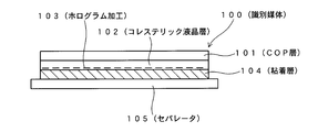
- FIG. 1 shows an identification medium 100.
- the identification medium 100 has a structure in which a COP layer 101, a cholesteric liquid crystal layer 102 with a hologram processing 103, an adhesive layer 104, and a separator 105, which is a release paper, are laminated from the observation side.
- the COP layer 101 is composed of a film made of a cycloolefin polymer, and functions as a base material that supports the surface protective layer and the cholesteric liquid crystal layer 102.
- the film of the cycloolefin polymer constituting the COP layer 101 has a property of transmitting visible light, and in the structure of this embodiment, the observation light is transmitted, so that it does not disturb the polarization state of the transmitted visible light. Have.
- the thickness of the COP layer 101 can be selected from the range of 10 ⁇ m to 200 ⁇ m.
- As the COP layer 101 for example, a ZEONOR film sold by Nippon Zeon Co., Ltd. can be used.
- the cycloolefin polymer is a thermoplastic plastic made from cyclopentagen present in the C5 fraction obtained when crude oil is decomposed.
- the C5 fraction is a hydrocarbon having 5 carbon atoms which is produced as a by-product by cracking naphtha obtained by distilling crude oil.
- the cholesteric liquid crystal layer 102 is, for example, a cholesteric liquid crystal layer set to an optical characteristic that selectively reflects red right circularly polarized light.
- the color of the reflected light selectively reflected by the cholesteric liquid crystal layer 102 may be other colors such as green.
- the turning direction of the reflected circularly polarized light is not limited to the right turn, and may be the left turn.
- the hologram processing 103 is performed by pressing a hologram mold against the cholesteric liquid crystal layer 102 to give an emboss structure.
- a hologram image resulting from the hologram processing 103 is observed.
- figures, patterns, characters, various designs, code display including digital image information, and the like are possible.
- the adhesive layer 104 is an adhesive layer, and has a function of attaching and fixing the identification medium 100 to an object.
- a dark pigment such as black or dark blue
- the pressure-sensitive adhesive layer 104 functions as a light absorption layer, and the discrimination effect using the reflected light of the cholesteric liquid crystal layer 102 is enhanced.
- the adhesive layer 104 can be a color other than dark or can be transparent.
- the separator 105 is a release paper that covers the exposed surface of the adhesive layer 104 when the identification medium 100 is not used.
- the separator 105 is peeled off, the adhesive layer 104 is exposed, and the adhesive layer 104 is brought into contact with the object.
- the identification medium 100 is attached to the object by the adhesive force of the adhesive layer 104 and is fixed to the object.
- a cholesteric liquid crystal layer 102 is grown on a substrate (not shown).
- the exposed surface of the cholesteric liquid crystal layer 102 is fixed to one surface of the COP layer 101 with an adhesive, and the substrate (not shown) is removed. In this way, a laminate of the COP layer 101 and the cholesteric liquid crystal layer 102 is obtained.
- a hologram processing 103 is performed by pressing a hologram mold against the exposed surface of the cholesteric liquid crystal layer 102.
- an adhesive layer 104 is formed on the surface of the cholesteric liquid crystal layer 102 on which the hologram processing 103 has been applied, and a separator 105 is attached to the exposed surface of the adhesive layer 104 to obtain the identification medium 100 shown in FIG.
- Optical function For example, a case where the cholesteric liquid crystal layer 102 selectively reflects red right circularly polarized light and the adhesive layer 104 is dark and light-absorbing will be described.
- the identification medium 100 when the identification medium 100 is directly viewed from the COP layer 101 side, the whole looks red and a hologram based on the hologram processing 103 is observed.
- the identification medium 100 when the identification medium 100 is tilted and the viewing angle is changed, the reflected light from the cholesteric liquid crystal layer 102 shows a color shift, and the observed color changes from red to the short wavelength side.
- the red right circular polarized light from the cholesteric liquid crystal layer 102 is preferentially observed, and the red hologram looks clearer.
- the reflected light from the cholesteric liquid crystal layer 102 shows a color shift, and the reflected light that has been seen in red shifts to the short wavelength side. A change in color tone such as orange is observed.
- the circular polarizing filter When the circular polarizing filter is replaced with the left circular polarizing filter, the red right circular polarized light reflected from the cholesteric liquid crystal layer 102 is blocked by the left circular polarizing filter, the cholesteric liquid crystal layer 102 becomes transparent, and the underlying adhesive layer 104 A dark color is observed. At this time, the hologram is not visible.
- the identification medium 100 has a structure in which the cholesteric liquid crystal layer 102 subjected to the hologram processing 103 is provided in contact with the COP (cycloolefin polymer) layer 101. According to this structure, the COP layer 101 is melted by the solvent and damaged when the identification medium 100 is peeled off using the solvent from the state of being stuck to the object by the adhesive layer 104.
- the COP layer 101 is a layer that also functions as a base material of the identification medium 100, and the identification medium 100 itself is damaged due to damage due to contact with the solvent, and it is difficult to reuse the medium.
- the cycloolefin polymer constituting the COP layer 101 has a chemical property that is very easy to deteriorate when it comes into contact with hydrocarbon solvents such as gasoline, kerosene, thinner, benzine, etc. It has the physical property of being easily torn and wrinkled when force is applied. For this reason, when the identification medium 100 is peeled off from the object using a solvent, or when the identification medium 100 is forcibly peeled off from the object, the COP layer 101 is easily damaged or has a trace. It is easy to remain. In particular, when a force is applied to the COP layer 101 in a state of being immersed in a solvent, the above-described tendency increases, so that the probability that reuse as an identification medium becomes impossible becomes higher.
- the cholesteric liquid crystal layer 102 and the adhesive layer 104 are soft materials and have almost no rigidity in themselves. For this reason, when the COP layer 101 is broken and broken, the cholesteric liquid crystal layer 102 and the adhesive layer 104 are broken together with the broken COP layer 101, and the identification medium 100 is damaged. The damaged identification medium 100 becomes difficult to reuse.
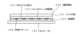
- FIG. 2 shows an identification medium 200.
- the identification medium 200 is an example in which a print pattern is provided on the surface (the lower surface in the drawing) opposite to the observation surface side of the cholesteric liquid crystal layer 102 in the identification medium 100 of FIG.
- Other configurations are the same as those of the identification medium 100 of FIG.
- the printing pattern 106 is formed by an ink jet method or other suitable printing method.
- the print pattern 106 various codes such as symbols, patterns, characters, and barcodes can be displayed.
- the identification medium 200 when the identification medium 200 is observed through the right circular polarizing filter, the reflected light from the cholesteric liquid crystal layer 102 is preferentially viewed, so that the red hologram looks clear. Also in this state, when the identification medium 200 is tilted, the reflected light from the cholesteric liquid crystal layer 102 shows a color shift, which is observed.
- the red right circular polarization from the cholesteric liquid crystal layer 102 is blocked by the left circular polarization filter, and the green pattern of the print pattern 106 is clearly observed.
- an identification medium 300 is shown.
- the identification medium 300 is printed from the observation side on the hard coat layer 107 serving as a protective layer, the cholesteric liquid crystal layer 102 on which the hologram processing 103 has been performed, and the surface opposite to the side on which the observation is performed (lower surface in the figure). It has a structure in which a COP layer 101 on which a pattern 106 is formed, an adhesive layer 104 and a separator 105 are laminated.
- the hard coat layer 107 is a coat layer made of an acrylic resin, a urethane resin, or the like, and is a resin layer that protects the surface on the observation surface side of the cholesteric liquid crystal layer 102.
- the hard coat layer 107 is selected to transmit visible light and not to disturb the polarization state of the transmitted light.
- the COP layer 101 is in contact with the surface opposite to the surface on which the cholesteric liquid crystal layer 102 is observed (the lower surface in the figure) and functions as a base material that supports the cholesteric liquid crystal layer 102.
- a print pattern 106 is formed on the surface of the COP layer 101 on the adhesive layer 104 side.
- optical function The optical function of the identification medium 300 is the same as that of the identification medium 200.
- an easily peelable substrate (not shown) that can be easily peeled off from the surface is prepared, and a hard coat layer 107 is formed thereon.
- the cholesteric liquid crystal layer 102 is formed on the exposed surface of the hard coat layer 107 (in FIG. 3, the lower surface side of the hard coat layer 107). This may be a method in which the cholesteric liquid crystal layer 102 is directly formed on the hard coat layer 107 or formed separately, and is placed on the hard coat layer 107 and fixed thereto.
- the hologram processing 103 is performed after forming the cholesteric liquid crystal layer 102 on the hard coat layer 107, and in the latter case, the hologram processing 103 is performed after forming the cholesteric liquid crystal layer 102 on another substrate.
- the exposed surface (the lower surface in FIG. 3) of the cholesteric liquid crystal layer 102 is fixed to the COP layer 101 with an adhesive, and then an easily peelable substrate (not shown) is peeled off from the hard coat layer 107.
- an easily peelable substrate (not shown) is peeled off from the hard coat layer 107.
- the print pattern 106 is formed on the exposed surface of the COP layer 101 by printing, and the adhesive layer 104 is further formed.
- the separator 105 is attached to the exposed surface of the adhesive layer 104 to obtain the identification medium 300 shown in FIG.
- FIG. 4 shows an identification medium 400.
- the identification medium 400 is configured such that holes or slits 108 are provided on the adhesive surface of the adhesive layer 104 in the identification medium 300 of FIG.
- the pressure-sensitive adhesive surface of the pressure-sensitive adhesive layer 104 is a surface to which the separator 105 is attached, and is a surface (a lower surface in the drawing) that comes into contact with the object when attached to the object.
- the hole or slit 108 is formed from the adhesive surface side (the surface side in contact with the separator 105) of the adhesive layer 104.
- the tip of the hole or slit 108 reaches the print pattern 106 in a portion where the print pattern 106 is present, and reaches the COP layer 101 in a portion where the print pattern 106 is absent. Note that a structure in which the tip of the hole or slit 108 does not accurately reach the printed pattern 106 and the COP layer 101 is possible, but a structure that reaches as close as possible is preferable.
- the hole or slit 108 is formed by applying a needle or a blade from the exposed surface (lower surface in the figure) side of the adhesive layer 104 after forming the adhesive layer 104.
- a needle or a blade from the exposed surface (lower surface in the figure) side of the adhesive layer 104 after forming the adhesive layer 104.
- it is formed by cutting the adhesive layer 104.
- the hole or slit 108 By providing the hole or slit 108, when a solvent is used to weaken the adhesive strength of the adhesive layer 104, the solvent penetrates from the hole or slit 108 to the COP layer 101 side and reaches the COP layer 101. Easy structure. Thereby, when the peeling action using the solvent is performed, a structure in which the COP layer 101 is more easily damaged is obtained. In addition, since the solvent easily reaches the print pattern 106 through the holes or slits 108, the ink constituting the print pattern 106 can be expected to be dissolved by the solvent, and in this respect also, there is a trace of illegal stripping using the solvent. Easy structure.
- a COP layer can be used instead of the hard coat layer 107.
- the COP layer 101 sandwiched between the cholesteric liquid crystal layer 102 and the adhesive layer 104 and the hard coat layer 107 functioning as a surface protective layer are used.
- the formed COP layer is damaged. For this reason, no matter how carefully the solvent is used, there is a very high possibility that it cannot be reused.
- a normal hologram layer may be adopted instead of the cholesteric liquid crystal layer 102.
- a portion of the cholesteric liquid crystal layer 102 is replaced with a hologram layer constituted by a transparent resin layer subjected to hologram processing by embossing and an aluminum vapor deposition layer formed thereon.
- FIG. 5 shows an identification medium 500.
- the identification medium 500 uses a circularly polarizing filter layer 111 having a structure in which a stretched COP layer 109 and a lyotropic liquid crystal dye layer 110 are laminated instead of the COP layer 101 in the identification medium 300 of FIG.
- the portions other than the circularly polarizing filter layer 111 are the same as those of the identification medium 300 in FIG.
- the stretched COP layer 109 is a film obtained by stretching a COP film in one direction so as to exhibit birefringence characteristics.
- a COP film is stretched so as to exhibit birefringence functioning as a ⁇ / 4 plate, and a stretched COP layer 109 is obtained.
- the stretched COP layer 109 also functions as a base material for the identification medium 500.
- the layer 110 of lyotropic liquid crystal dye functions as a linearly polarizing layer (linearly polarizing filter) that selectively transmits linearly polarized light in a specific polarization direction.
- the circularly polarizing filter layer 111 converts the reflected light from the print pattern 106 (reflected light in the upward direction in the figure) into right-turning or left-turning circularly polarized light. In other words, the circularly polarizing filter layer 111 selectively transmits only circularly polarized light in a specific turning direction as reflected light from the print pattern 106 in the upward direction in the drawing.
- the rotational direction of the circularly polarized light that is selectively transmitted by the circularly polarizing filter layer 111 is set to be opposite to the rotational direction of the circularly polarized light that is selectively reflected by the cholesteric liquid crystal layer 102.
- the circularly polarized filter layer 111 is set to selectively transmit left circularly polarized light upward in the figure, and the cholesteric liquid crystal layer 102 reflects left circularly polarized light.
- the circularly polarizing filter layer 111 is set to selectively transmit the right circularly polarized light upward in the figure.
- the layer 110 of the lyotropic liquid crystal dye has a structure in which layers in which a pigment is aligned in one direction are stacked in multiple layers, and this structure exhibits a property of selectively transmitting linearly polarized light in a specific direction.
- the layer 110 of the lyotropic liquid crystal dye is formed by being applied to the exposed surface of the stretched COP layer 109 in a state where the dye is oriented using a slit die coater or the like.
- the slit die coater can be stretched in the coating direction while applying a pressure to the material while supplying the polarizing layer material in a solution state to the coating surface.
- a coating-type polarizing layer having the property that the dye is oriented in a specific direction and selectively transmits linearly polarized light is formed.
- the coating type polarizing layer is formed as a lyotropic liquid crystal phase that expresses a chromonic phase obtained by sulfonating an indanthrone derivative, a dibenzimidazole derivative of perylenetetracarboxylic acid or a naphthalenetetracarboxylic acid derivative.
- This coating type polarizing layer is insolubilized by desulfonization with barium chloride.
- the coating-type polarizing layer is multilayered to form the lyotropic liquid crystal dye layer 110 that functions as a linear polarizing layer.
- the orientation of the pigment in the layer 110 of the lyotropic liquid crystal dye can be provided by an orientation film or other orientation treatment methods.
- the layer 110 of the lyotropic liquid crystal dye is a material that is soluble in a hydrocarbon solvent such as thinner or benzine.
- materials that can be used for the same purpose include liquid crystals to which a dichroic dye is added as described in JP-A-2001-330726 in addition to the lyotropic liquid crystal dyes described above.
- Optical function For example, it is assumed that the cholesteric liquid crystal layer 102 is set to selectively reflect right circularly polarized light, and the circularly polarized filter layer 111 is set to selectively transmit left circularly polarized light.
- the reflected light from the cholesteric liquid crystal layer 102 passes through the viewer, so that the hologram image resulting from the hologram processing 103 can be visually recognized.
- the reflected light from the print pattern 106 becomes linearly polarized light when it passes through the lyotropic liquid crystal dye layer 110 that is a linearly polarizing layer, and further passes through the stretched COP layer 109 that is a ⁇ / 4 plate.
- Left circularly polarized light is blocked by the viewer, which is a right circularly polarized filter, and is not visible. That is, the hologram image resulting from the hologram processing 103 can be visually recognized, but the reflected light from the print pattern 106 cannot be visually recognized.
- the identification medium 500 when the identification medium 500 is observed through the viewer of the left circular polarizing filter, the reflected light of the right circular polarized light from the cholesteric liquid crystal layer 102 is blocked by the viewer, but the reflected light from the print pattern is reflected by the circular polarizing filter. Since the layer 111 is transmitted in the upward direction in the figure in the state of left circularly polarized light, it is visible through the viewer of the left circularly polarized filter. That is, the hologram image resulting from the hologram processing 103 cannot be visually recognized, but the reflected light from the print pattern 106 can be visually recognized.
- the state in which the hologram image resulting from the hologram processing 103 is selectively visible and the state in which the print pattern 106 is selectively visible are switched. High discriminability can be obtained by this appearance change.
- the linear polarizing layer is not a coating-type polarizing layer but a general linear polarizing film
- the linear polarizing film is made by adsorbing a dichroic dye such as iodine and stretching PVA between TAC films. Since these materials do not dissolve or deteriorate with a hydrocarbon-based solvent, the above advantages are lower than when a coating-type polarizing layer is used.
- the adhesive layer 104 may be made of a transparent material.
- the design on the surface of the target object to which the identification medium 500 is attached can be used as an identification target similar to the print pattern 106.
- a structure in which the print pattern 106 is not provided is also possible.
- the design of the surface of the target object to which the identification medium 500 is attached becomes the design of the identification target similar to the print pattern 106.
- the configurations in the first to seventh embodiments can be used in any combination of some or more.
- a structure in which holes or slits 108 provided in the adhesive layer 104 of the identification medium 400 of FIG. 4 are provided in the adhesive layer 104 of the identification medium 500 of FIG. 5 is possible.
- the present invention can be used for a technique for identifying authenticity.
Landscapes
- Physics & Mathematics (AREA)
- Chemical & Material Sciences (AREA)
- General Physics & Mathematics (AREA)
- Engineering & Computer Science (AREA)
- Chemical Kinetics & Catalysis (AREA)
- Health & Medical Sciences (AREA)
- Theoretical Computer Science (AREA)
- Optics & Photonics (AREA)
- Crystallography & Structural Chemistry (AREA)
- Organic Chemistry (AREA)
- Polymers & Plastics (AREA)
- Medicinal Chemistry (AREA)
- Computer Security & Cryptography (AREA)
- Manufacturing & Machinery (AREA)
- Toxicology (AREA)
- General Health & Medical Sciences (AREA)
- General Chemical & Material Sciences (AREA)
- Polarising Elements (AREA)
- Credit Cards Or The Like (AREA)
- Diffracting Gratings Or Hologram Optical Elements (AREA)
Abstract
Description
(構成)
図1には、識別媒体100が示されている。識別媒体100は、観察を行う側からCOP層101、ホログラム加工103が施されたコレステリック液晶層102、粘着層104、離型紙であるセパレータ105と積層された構造を有している。 (1) First embodiment (configuration)
FIG. 1 shows an identification medium 100. The identification medium 100 has a structure in which a COP layer 101, a cholesteric liquid crystal layer 102 with a hologram processing 103, an adhesive layer 104, and a separator 105, which is a release paper, are laminated from the observation side.
まず図示しない基板上でコレステリック液晶層102を成長させる。次いで、コレステリック液晶層102の露出面をCOP層101の片面に接着剤によって固定し、上記図示しない基板を剥がす。こうして、COP層101とコレステリック液晶層102の積層物を得る。次に、コレステリック液晶層102の露出面にホログラム型を押し付けることで、ホログラム加工103を施す。そして、コレステリック液晶層102のホログラム加工103が施された面に粘着層104を形成し、さらに粘着層104の露出面にセパレータ105を貼り付け、図1に示す識別媒体100を得る。 (Production method)
First, a cholesteric liquid crystal layer 102 is grown on a substrate (not shown). Next, the exposed surface of the cholesteric liquid crystal layer 102 is fixed to one surface of the COP layer 101 with an adhesive, and the substrate (not shown) is removed. In this way, a laminate of the COP layer 101 and the cholesteric liquid crystal layer 102 is obtained. Next, a hologram processing 103 is performed by pressing a hologram mold against the exposed surface of the cholesteric liquid crystal layer 102. Then, an adhesive layer 104 is formed on the surface of the cholesteric liquid crystal layer 102 on which the hologram processing 103 has been applied, and a separator 105 is attached to the exposed surface of the adhesive layer 104 to obtain the identification medium 100 shown in FIG.
例えば、コレステリック液晶層102が赤の右円偏光を選択反射し、粘着層104が暗色で光吸収性である場合を説明する。この場合、COP層101側から識別媒体100を直視すると、全体が赤く見え、ホログラム加工103に基づくホログラムが観察される。そして、この状態で識別媒体100を傾け、見る角度を変化させるとコレステリック液晶層102からの反射光がカラーシフトを示し、観察される色が赤から短波長側に変化する。 (Optical function)
For example, a case where the cholesteric liquid crystal layer 102 selectively reflects red right circularly polarized light and the adhesive layer 104 is dark and light-absorbing will be described. In this case, when the identification medium 100 is directly viewed from the COP layer 101 side, the whole looks red and a hologram based on the hologram processing 103 is observed. In this state, when the identification medium 100 is tilted and the viewing angle is changed, the reflected light from the cholesteric liquid crystal layer 102 shows a color shift, and the observed color changes from red to the short wavelength side.
以上述べたように、識別媒体100は、ホログラム加工103が施されたコレステリック液晶層102をCOP(シクロオレフィンポリマー)層101に接して設けた構造とされている。この構造によれば、粘着層104によって対象物に貼り付けられた状態から識別媒体100を溶剤を用いて剥がそうとした際にCOP層101が溶剤によって溶けて破損する。COP層101は、識別媒体100の基材としても機能する層であり、上記の溶剤に触れることでの破損により、識別媒体100自体が破損し、その再利用が困難となる。 (Superiority)
As described above, the identification medium 100 has a structure in which the cholesteric liquid crystal layer 102 subjected to the hologram processing 103 is provided in contact with the COP (cycloolefin polymer) layer 101. According to this structure, the COP layer 101 is melted by the solvent and damaged when the identification medium 100 is peeled off using the solvent from the state of being stuck to the object by the adhesive layer 104. The COP layer 101 is a layer that also functions as a base material of the identification medium 100, and the identification medium 100 itself is damaged due to damage due to contact with the solvent, and it is difficult to reuse the medium.
(構成)
図2には、識別媒体200が示されている。識別媒体200は、図1の識別媒体100において、コレステリック液晶層102の観察面側と反対側の面(図の下面)に印刷パターンを設けた例である。他の構成は、図1の識別媒体100と同じである。この場合、コレステリック液晶層102にホログラム加工103を施した後に、インクジェット法やその他適当な印刷方法により印刷パターン106を形成する。印刷パターン106としては、図柄、模様、文字、バーコード等の各種コード表示が可能である。 (2) Second embodiment (configuration)
FIG. 2 shows an identification medium 200. The identification medium 200 is an example in which a print pattern is provided on the surface (the lower surface in the drawing) opposite to the observation surface side of the cholesteric liquid crystal layer 102 in the identification medium 100 of FIG. Other configurations are the same as those of the identification medium 100 of FIG. In this case, after applying the hologram processing 103 to the cholesteric liquid crystal layer 102, the printing pattern 106 is formed by an ink jet method or other suitable printing method. As the print pattern 106, various codes such as symbols, patterns, characters, and barcodes can be displayed.
仮に、粘着層104が暗色で、印刷パターンが緑であり、コレステリック液晶層102が赤の右円偏光を選択反射する設定であるとする。この場合、COP層101側から識別媒体100を直視すると、全体が赤く見え、ホログラム加工103に基づくホログラムが観察され、また印刷パターン106が薄く見える。そして、この状態で識別媒体100を傾け、見る角度を変化させるとコレステリック液晶層102からの反射光がカラーシフトを示し、赤から短波長側に色調が変化する。 (Optical function)
Assume that the adhesive layer 104 is dark, the printing pattern is green, and the cholesteric liquid crystal layer 102 is configured to selectively reflect red circularly polarized light. In this case, when the identification medium 100 is directly viewed from the COP layer 101 side, the whole appears red, a hologram based on the hologram processing 103 is observed, and the printed pattern 106 appears thin. In this state, when the identification medium 100 is tilted and the viewing angle is changed, the reflected light from the cholesteric liquid crystal layer 102 shows a color shift, and the color tone changes from red to the short wavelength side.
識別媒体200の場合も溶剤を用いた不正な剥がし行為や物理的な無理な剥がし行為が行われると、COP層101の破損が発生し、識別媒体200自体が破損し、再利用ができなくなる。 (Superiority)
Also in the case of the identification medium 200, if an illegal peeling action using a solvent or a physical unreasonable peeling action is performed, the COP layer 101 is damaged, and the identification medium 200 itself is damaged and cannot be reused.
(構成)
図3には、識別媒体300が示されている。識別媒体300は、観察が行われる側から、保護層となるハードコート層107、ホログラム加工103が施されたコレステリック液晶層102、観察が行われる側と反対側の面(図の下面)に印刷パターン106が形成されたCOP層101、粘着層104、セパレータ105と積層された構造を有している。 (3) Third embodiment (configuration)
In FIG. 3, an identification medium 300 is shown. The identification medium 300 is printed from the observation side on the hard coat layer 107 serving as a protective layer, the cholesteric liquid crystal layer 102 on which the hologram processing 103 has been performed, and the surface opposite to the side on which the observation is performed (lower surface in the figure). It has a structure in which a COP layer 101 on which a pattern 106 is formed, an adhesive layer 104 and a separator 105 are laminated.
識別媒体300の光学機能は、識別媒体200と同じである。 (Optical function)
The optical function of the identification medium 300 is the same as that of the identification medium 200.
まず、その表面からの剥離が容易な図示しない易剥離性の基板を用意し、その上にハードコート層107を形成する。次にハードコート層107の露出面(図3でいうとハードコート層107の下面側)にコレステリック液晶層102を形成する。これは、コレステリック液晶層102をハードコート層107上に直接形成してもよいし、別に形成し、それをハードコート層107に載せ代え、そこに固定する方法であってもよい。なお、前者の場合、ホログラム加工103は、ハードコート層107上にコレステリック液晶層102を形成した後に施し、後者の場合、ホログラム加工103は、別基板上でコレステリック液晶層102を形成した後に施す。 (Production method)
First, an easily peelable substrate (not shown) that can be easily peeled off from the surface is prepared, and a hard coat layer 107 is formed thereon. Next, the cholesteric liquid crystal layer 102 is formed on the exposed surface of the hard coat layer 107 (in FIG. 3, the lower surface side of the hard coat layer 107). This may be a method in which the cholesteric liquid crystal layer 102 is directly formed on the hard coat layer 107 or formed separately, and is placed on the hard coat layer 107 and fixed thereto. In the former case, the hologram processing 103 is performed after forming the cholesteric liquid crystal layer 102 on the hard coat layer 107, and in the latter case, the hologram processing 103 is performed after forming the cholesteric liquid crystal layer 102 on another substrate.
識別媒体300が対象物に貼り付いている状態において、溶剤を用いて識別媒体300を対象物から剥がそうとした場合、COP層101が溶剤で溶けて破損する。特に、識別媒体300では、COP層101が粘着層104に接触しているため、粘着層104を溶かす目的で用いられる溶剤がCOP層101に接触し易い。このため、溶剤を用いた不正な剥がし行為に際して、COP層101の破損がより生じ易い。また、COP層101が溶剤で溶けると、印刷パターン106の表示内容が崩れ、その痕跡が明確に残る状態となる。この点でも、不正な剥がし行為の痕跡が明確に生じやすいという点で有利となる。 (Superiority)
In a state where the identification medium 300 is attached to the object, when the solvent 300 is used to peel the identification medium 300 from the object, the COP layer 101 is dissolved by the solvent and damaged. In particular, in the identification medium 300, since the COP layer 101 is in contact with the adhesive layer 104, a solvent used for dissolving the adhesive layer 104 is likely to contact the COP layer 101. For this reason, damage to the COP layer 101 is more likely to occur during an illegal stripping operation using a solvent. Further, when the COP layer 101 is dissolved with a solvent, the display content of the print pattern 106 is destroyed, and the trace remains clearly. This is also advantageous in that traces of illegal stripping actions are likely to occur clearly.
図4には、識別媒体400が示されている。識別媒体400は、図3の識別媒体300において、粘着層104の粘着面に穴またはスリット108を設けた構成とされている。ここで、粘着層104の粘着面は、セパレータ105が貼り付けられている面であり、対象物に貼り付けた際に、対象物に接触する側の面(図の下面)である。 (4) Fourth Embodiment FIG. 4 shows an identification medium 400. The identification medium 400 is configured such that holes or slits 108 are provided on the adhesive surface of the adhesive layer 104 in the identification medium 300 of FIG. Here, the pressure-sensitive adhesive surface of the pressure-sensitive adhesive layer 104 is a surface to which the separator 105 is attached, and is a surface (a lower surface in the drawing) that comes into contact with the object when attached to the object.
図3または図4に示す構成において、ハードコート層107の代わりにCOP層を用いることもできる。この構成では、当該識別媒体が溶剤に触れた場合に、コレステリック液晶層102と粘着層104との間に挟まれているCOP層101、および表面保護層として機能するハードコート層107の部分に用いられたCOP層が破損する。このため、どのように注意深く溶剤を用いたとしても再利用が不可能となる可能性が極めて高くなる。 (5) Fifth Embodiment In the configuration shown in FIG. 3 or 4, a COP layer can be used instead of the hard coat layer 107. In this configuration, when the identification medium comes into contact with a solvent, the COP layer 101 sandwiched between the cholesteric liquid crystal layer 102 and the adhesive layer 104 and the hard coat layer 107 functioning as a surface protective layer are used. The formed COP layer is damaged. For this reason, no matter how carefully the solvent is used, there is a very high possibility that it cannot be reused.
図1に示す構造において、コレステリック液晶層102の代わりに、通常のホログラム層を採用してもよい。この場合、例えばコレステリック液晶層102の部分が、エンボス加工によるホログラム加工が施された透明な樹脂層、その上に形成されたアルミ蒸着層により構成されたホログラム層に置き換えられる。 (6) Sixth Embodiment In the structure shown in FIG. 1, a normal hologram layer may be adopted instead of the cholesteric liquid crystal layer 102. In this case, for example, a portion of the cholesteric liquid crystal layer 102 is replaced with a hologram layer constituted by a transparent resin layer subjected to hologram processing by embossing and an aluminum vapor deposition layer formed thereon.
(構成)
図3に示す構造において、COP層101の代わりに延伸COP層を用いた円偏光フィルタ層を採用してもよい。以下、この一例を説明する。図5には、識別媒体500が示されている。識別媒体500は、図3の識別媒体300において、COP層101の代わりに延伸COP層109とリオトロピック液晶染料の層110を積層した構造の円偏光フィルタ層111を用いている。なお、円偏光フィルタ層111以外の部分は、図3の識別媒体300と同じである。 (7) Seventh embodiment (configuration)
In the structure shown in FIG. 3, a circularly polarizing filter layer using a stretched COP layer instead of the COP layer 101 may be employed. Hereinafter, this example will be described. FIG. 5 shows an identification medium 500. The identification medium 500 uses a circularly polarizing filter layer 111 having a structure in which a stretched COP layer 109 and a lyotropic liquid crystal dye layer 110 are laminated instead of the COP layer 101 in the identification medium 300 of FIG. The portions other than the circularly polarizing filter layer 111 are the same as those of the identification medium 300 in FIG.
例えば、コレステリック液晶層102が右円偏光を選択反射する設定とされ、円偏光フィルタ層111が左円偏光を選択的に透過する設定とされているとする。 (Optical function)
For example, it is assumed that the cholesteric liquid crystal layer 102 is set to selectively reflect right circularly polarized light, and the circularly polarized filter layer 111 is set to selectively transmit left circularly polarized light.
粘着層104の粘着力を炭化水素系の溶剤で低下させようとすると、塗布型偏光層により構成されたリオトロピック液晶染料の層110が溶剤により溶け、更に延伸COP層109が溶剤に触れ、延伸COP層109が溶剤により破壊される。これにより、延伸COP層109の基材としての機能が失われ識別媒体500が物理的に破壊される。また、円偏光フィルタ層111の光学機能が失われる。仮に、物理的な破壊が不完全な場合でも円偏光フィルタ層111の光学機能が低下することで、上述した見た目で顕著な違いが認識可能な光学機能が部分的であっても損なわれ、不正利用の痕跡が視覚的に明確に確認できる状態となる。このため、溶剤を用いて対象物から不正に剥がして再利用することの困難性が極めて高くなる。仮に、直線偏光層を塗布型偏光層でなく、一般的な直線偏光フィルムで構成した場合、直線偏光フィルムはヨウ素等の二色性色素を吸着させてPVAを延伸したものをTACフィルムで挟んだ構成となっており、これらの材料は炭化水素系の溶剤で溶けたり、劣化したりしないため、塗布型偏光層を利用した場合に比較して上記の優位性は低くなる。 (Superiority)
When the adhesive strength of the adhesive layer 104 is reduced with a hydrocarbon solvent, the lyotropic liquid crystal dye layer 110 constituted by the coating type polarizing layer is dissolved by the solvent, and the stretched COP layer 109 is in contact with the solvent. Layer 109 is destroyed by the solvent. As a result, the function of the stretched COP layer 109 as a base material is lost, and the identification medium 500 is physically destroyed. Further, the optical function of the circularly polarizing filter layer 111 is lost. Even if the physical destruction is incomplete, the optical function of the circularly polarizing filter layer 111 is lowered, so that even if the optical function that can recognize a noticeable difference is partially damaged, it is illegal. It will be in a state where the trace of use can be visually confirmed clearly. For this reason, the difficulty of illegally peeling from a target object using a solvent and reusing it becomes very high. If the linear polarizing layer is not a coating-type polarizing layer but a general linear polarizing film, the linear polarizing film is made by adsorbing a dichroic dye such as iodine and stretching PVA between TAC films. Since these materials do not dissolve or deteriorate with a hydrocarbon-based solvent, the above advantages are lower than when a coating-type polarizing layer is used.
図5の識別媒体500において、粘着層104を透明な材質としてもよい。この場合、印刷パターン106に加えて、識別媒体500が貼り付けられる対象物の表面の図柄を、印刷パターン106と同様な識別の対象として利用することができる。また、この構成において、印刷パターン106を設けない構造も可能である。この場合、識別媒体500が貼り付けられる対象物の表面の図柄が印刷パターン106と同様な識別対象の図柄となる。 (8) Eighth Embodiment In the identification medium 500 of FIG. 5, the adhesive layer 104 may be made of a transparent material. In this case, in addition to the print pattern 106, the design on the surface of the target object to which the identification medium 500 is attached can be used as an identification target similar to the print pattern 106. In this configuration, a structure in which the print pattern 106 is not provided is also possible. In this case, the design of the surface of the target object to which the identification medium 500 is attached becomes the design of the identification target similar to the print pattern 106.
第1~第7の実施形態における構成は、その一部または複数を任意に組み合わせて用いることが可能である。たとえば、図5の識別媒体500の粘着層104に、図4の識別媒体400の粘着層104に設けられている孔またはスリット108を設ける構造等が可能である。 (Other)
The configurations in the first to seventh embodiments can be used in any combination of some or more. For example, a structure in which holes or slits 108 provided in the adhesive layer 104 of the identification medium 400 of FIG. 4 are provided in the adhesive layer 104 of the identification medium 500 of FIG. 5 is possible.
Claims (10)
- 識別機能を示す光学機能層と、
前記光学機能層の基材として機能するシクロオレフィンポリマーの層と
を備えることを特徴とする識別媒体。 An optical functional layer showing an identification function;
An identification medium comprising: a layer of a cycloolefin polymer that functions as a base material for the optical functional layer. - 観察が行われる側の面から、
前記シクロオレフィンポリマーの層と、
前記光学機能層と、
粘着層と
の順で積層された構造を有することを特徴とする請求項1に記載の識別媒体。 From the side where the observation takes place,
A layer of said cycloolefin polymer;
The optical functional layer;
The identification medium according to claim 1, having a structure in which the adhesive layer and the adhesive layer are laminated in this order. - 観察が行われる側の面から、
前記光学機能層と、
前記シクロオレフィンポリマーの層と、
粘着層と
の順に積層された構造を有することを特徴とする請求項1または2に記載の識別媒体。 From the side where the observation takes place,
The optical functional layer;
A layer of said cycloolefin polymer;
The identification medium according to claim 1, wherein the identification medium has a structure in which the adhesive layer is laminated in this order. - 前記シクロオレフィンポリマーの層の前記粘着層の側に印刷パターンが形成されていることを特徴とする請求項3に記載の識別媒体。 The identification medium according to claim 3, wherein a printed pattern is formed on the adhesive layer side of the cycloolefin polymer layer.
- 前記粘着層の粘着面には、穴またはスリットが形成されていることを特徴とする請求項3または4に記載の識別媒体。 The identification medium according to claim 3 or 4, wherein a hole or a slit is formed in the adhesive surface of the adhesive layer.
- 前記穴またはスリットの先端が前記シクロオレフィンポリマーの層に到達していることを特徴とする請求項5に記載の識別媒体。 6. The identification medium according to claim 5, wherein a tip of the hole or slit reaches the cycloolefin polymer layer.
- 前記光学機能層としてホログラム加工が施されたコレステリック液晶が採用されていることを特徴とする請求項1~6のいずれか一項に記載の識別媒体。 The identification medium according to any one of claims 1 to 6, wherein a cholesteric liquid crystal subjected to hologram processing is employed as the optical functional layer.
- 観察が行われる側の面から、
前記光学機能層と、
前記シクロオレフィンポリマーの層と、
溶剤で溶ける材質により構成される直線偏光層と、
粘着層と
の順に積層された構造を有し、
前記光学機能層がコレステリック液晶層であり、
前記シクロオレフィンポリマーの層は、延伸されることで複屈折性が与えられたλ/4板であり、
前記シクロオレフィンポリマーの層と前記直線偏光層とにより、前記粘着層の側から前記光学機能層の側に特定の旋回方向の円偏光を選択的に透過する円偏光フィルタ層が構成され、
前記円偏光フィルタ層が選択的に透過する円偏光の旋回方向と前記コレステリック液晶層が選択反射する円偏光の旋回方向とが逆であることを特徴とする請求項1~7のいずれか一項に記載の識別媒体。 From the side where the observation takes place,
The optical functional layer;
A layer of said cycloolefin polymer;
A linearly polarizing layer composed of a material that is soluble in a solvent;
It has a structure laminated in order with the adhesive layer,
The optical functional layer is a cholesteric liquid crystal layer;
The cycloolefin polymer layer is a λ / 4 plate that has been given birefringence by being stretched,
The cycloolefin polymer layer and the linearly polarizing layer constitute a circularly polarizing filter layer that selectively transmits circularly polarized light in a specific turning direction from the adhesive layer side to the optical functional layer side,
The rotational direction of circularly polarized light selectively transmitted by the circularly polarizing filter layer and the rotational direction of circularly polarized light selectively reflected by the cholesteric liquid crystal layer are opposite to each other. The identification medium described in 1. - 前記溶剤で溶ける材質により構成される直線偏光層は、塗布型偏光層により構成されていることを特徴とする請求項8に記載の識別媒体。 9. The identification medium according to claim 8, wherein the linearly polarizing layer made of a material soluble in the solvent is made of a coating type polarizing layer.
- 前記塗布型偏光層がリオトロピック液晶染料の層により構成されていることを特徴とする請求項9に記載の識別媒体。 10. The identification medium according to claim 9, wherein the coating-type polarizing layer is composed of a layer of lyotropic liquid crystal dye.
Priority Applications (4)
| Application Number | Priority Date | Filing Date | Title |
|---|---|---|---|
| EP12768152.6A EP2696334A4 (en) | 2011-04-01 | 2012-02-21 | Distinguishing medium |
| JP2013508791A JP5769797B2 (en) | 2011-04-01 | 2012-02-21 | Identification medium |
| US14/008,857 US20140160540A1 (en) | 2011-04-01 | 2012-02-21 | Identification medium |
| CN2012800166167A CN103460267A (en) | 2011-04-01 | 2012-02-21 | Distinguishing medium |
Applications Claiming Priority (2)
| Application Number | Priority Date | Filing Date | Title |
|---|---|---|---|
| JP2011-081596 | 2011-04-01 | ||
| JP2011081596 | 2011-04-01 |
Publications (1)
| Publication Number | Publication Date |
|---|---|
| WO2012137550A1 true WO2012137550A1 (en) | 2012-10-11 |
Family
ID=46968954
Family Applications (1)
| Application Number | Title | Priority Date | Filing Date |
|---|---|---|---|
| PCT/JP2012/054098 WO2012137550A1 (en) | 2011-04-01 | 2012-02-21 | Distinguishing medium |
Country Status (5)
| Country | Link |
|---|---|
| US (1) | US20140160540A1 (en) |
| EP (1) | EP2696334A4 (en) |
| JP (1) | JP5769797B2 (en) |
| CN (1) | CN103460267A (en) |
| WO (1) | WO2012137550A1 (en) |
Cited By (5)
| Publication number | Priority date | Publication date | Assignee | Title |
|---|---|---|---|---|
| WO2014061489A1 (en) * | 2012-10-19 | 2014-04-24 | 日本発條株式会社 | Covering member |
| WO2018079606A1 (en) * | 2016-10-25 | 2018-05-03 | 富士フイルム株式会社 | Transmissive decorative film and production method for transmissive decorative film |
| JPWO2017110225A1 (en) * | 2015-12-25 | 2018-10-18 | Jxtgエネルギー株式会社 | Optical film |
| WO2019176880A1 (en) * | 2018-03-16 | 2019-09-19 | 日本ゼオン株式会社 | Viewer for determining authenticity, photographing device, and method for determining authenticity |
| WO2020203574A1 (en) * | 2019-03-29 | 2020-10-08 | 富士フイルム株式会社 | Reflective sheet, and transfer film for reflective sheet |
Families Citing this family (5)
| Publication number | Priority date | Publication date | Assignee | Title |
|---|---|---|---|---|
| TW201502257A (en) * | 2013-07-10 | 2015-01-16 | Sicpa Holding Sa | Marking comprising a printable code and a chiral liquid crystal polymer layer |
| DE102014117877A1 (en) * | 2014-12-04 | 2016-06-23 | Leonhard Kurz Stiftung & Co. Kg | security element |
| CN108461033A (en) * | 2018-03-07 | 2018-08-28 | 厦门吉宏包装科技股份有限公司 | A kind of antifalse material and its processing technology |
| CN110136565A (en) * | 2019-06-26 | 2019-08-16 | 山东泰宝防伪技术产品有限公司 | On-Screen Identification liquid crystal anti-counterfeiting mark and preparation method thereof |
| US20220113459A1 (en) * | 2020-10-08 | 2022-04-14 | Facebook Technologies, Llc | Polarization selective optical element and fabrication method |
Citations (9)
| Publication number | Priority date | Publication date | Assignee | Title |
|---|---|---|---|---|
| JPH10250225A (en) | 1997-03-12 | 1998-09-22 | Mitsubishi Chem Corp | Optical information recording medium and optical recording method |
| JPH10268772A (en) | 1997-03-26 | 1998-10-09 | Mitsubishi Paper Mills Ltd | Sheet and adhesive label for prevention against forgery |
| JP2001330726A (en) | 2000-05-22 | 2001-11-30 | Dainippon Printing Co Ltd | Polarizing element and method for manufacturing polarizing element |
| JP2007102203A (en) * | 2005-09-07 | 2007-04-19 | Dainippon Printing Co Ltd | Genuineness display body |
| JP2010250025A (en) | 2009-04-14 | 2010-11-04 | Hitachi Displays Ltd | Polarization element, method for manufacturing the same, and liquid crystal display |
| JP2011174978A (en) * | 2010-02-23 | 2011-09-08 | Sony Corp | Hologram recording medium |
| JP4868090B2 (en) * | 2009-10-16 | 2012-02-01 | 凸版印刷株式会社 | Image display body, labeled article and manufacturing method thereof |
| JP2012093674A (en) * | 2010-10-29 | 2012-05-17 | Sealex Corp | Alteration prevention seal |
| JP2012098348A (en) * | 2010-10-29 | 2012-05-24 | Toppan Printing Co Ltd | Display body |
Family Cites Families (9)
| Publication number | Priority date | Publication date | Assignee | Title |
|---|---|---|---|---|
| DE10030235A1 (en) * | 2000-06-20 | 2002-01-03 | Mitsubishi Polyester Film Gmbh | White, sealable, thermoformable, biaxially oriented and coextruded polyester film with cycloolefin copolymer, process for its production and its use |
| KR100839402B1 (en) * | 2002-07-23 | 2008-06-20 | 닛토덴코 가부시키가이샤 | Optical film and liquid crystal display device using the same |
| ATE357004T1 (en) * | 2003-08-29 | 2007-04-15 | Nippon Carbide Kogyo Kk | RETRO-REFLECTIVE SHEET WITH A FRAGIBLE LAYER |
| US7909364B2 (en) * | 2005-09-07 | 2011-03-22 | Dai Nippon Printing Co., Ltd. | Indicator for indicating authenticity |
| JP2007069486A (en) * | 2005-09-07 | 2007-03-22 | Dainippon Printing Co Ltd | Method for manufacturing cholesteric liquid crystal medium with cubic hologram |
| JP4959304B2 (en) * | 2006-11-22 | 2012-06-20 | 日本発條株式会社 | Identification medium, identification method, and identification apparatus |
| JP2009086379A (en) * | 2007-09-28 | 2009-04-23 | Fujifilm Corp | Optical compensation film, polarizing plate, and liquid crystal display device |
| WO2010071956A1 (en) * | 2008-12-22 | 2010-07-01 | Canadian Bank Note Company, Limited | Improved printing of tactile marks for the visually impaired |
| JP5647047B2 (en) * | 2011-03-18 | 2014-12-24 | 日本発條株式会社 | Identification medium |
-
2012
- 2012-02-21 WO PCT/JP2012/054098 patent/WO2012137550A1/en active Application Filing
- 2012-02-21 CN CN2012800166167A patent/CN103460267A/en active Pending
- 2012-02-21 EP EP12768152.6A patent/EP2696334A4/en not_active Withdrawn
- 2012-02-21 JP JP2013508791A patent/JP5769797B2/en active Active
- 2012-02-21 US US14/008,857 patent/US20140160540A1/en not_active Abandoned
Patent Citations (9)
| Publication number | Priority date | Publication date | Assignee | Title |
|---|---|---|---|---|
| JPH10250225A (en) | 1997-03-12 | 1998-09-22 | Mitsubishi Chem Corp | Optical information recording medium and optical recording method |
| JPH10268772A (en) | 1997-03-26 | 1998-10-09 | Mitsubishi Paper Mills Ltd | Sheet and adhesive label for prevention against forgery |
| JP2001330726A (en) | 2000-05-22 | 2001-11-30 | Dainippon Printing Co Ltd | Polarizing element and method for manufacturing polarizing element |
| JP2007102203A (en) * | 2005-09-07 | 2007-04-19 | Dainippon Printing Co Ltd | Genuineness display body |
| JP2010250025A (en) | 2009-04-14 | 2010-11-04 | Hitachi Displays Ltd | Polarization element, method for manufacturing the same, and liquid crystal display |
| JP4868090B2 (en) * | 2009-10-16 | 2012-02-01 | 凸版印刷株式会社 | Image display body, labeled article and manufacturing method thereof |
| JP2011174978A (en) * | 2010-02-23 | 2011-09-08 | Sony Corp | Hologram recording medium |
| JP2012093674A (en) * | 2010-10-29 | 2012-05-17 | Sealex Corp | Alteration prevention seal |
| JP2012098348A (en) * | 2010-10-29 | 2012-05-24 | Toppan Printing Co Ltd | Display body |
Non-Patent Citations (1)
| Title |
|---|
| See also references of EP2696334A4 |
Cited By (13)
| Publication number | Priority date | Publication date | Assignee | Title |
|---|---|---|---|---|
| JP2014085393A (en) * | 2012-10-19 | 2014-05-12 | Nhk Spring Co Ltd | Coating member |
| WO2014061489A1 (en) * | 2012-10-19 | 2014-04-24 | 日本発條株式会社 | Covering member |
| JPWO2017110225A1 (en) * | 2015-12-25 | 2018-10-18 | Jxtgエネルギー株式会社 | Optical film |
| US10690827B2 (en) | 2016-10-25 | 2020-06-23 | Fujifilm Corporation | Transmission decorative film and method of manufacturing transmission decorative film |
| JPWO2018079606A1 (en) * | 2016-10-25 | 2019-07-18 | 富士フイルム株式会社 | Transparent decorative film and method of manufacturing transparent decorative film |
| WO2018079606A1 (en) * | 2016-10-25 | 2018-05-03 | 富士フイルム株式会社 | Transmissive decorative film and production method for transmissive decorative film |
| WO2019176880A1 (en) * | 2018-03-16 | 2019-09-19 | 日本ゼオン株式会社 | Viewer for determining authenticity, photographing device, and method for determining authenticity |
| JPWO2019176880A1 (en) * | 2018-03-16 | 2021-04-08 | 日本ゼオン株式会社 | Authenticity judgment viewer, imaging device, and authenticity judgment method |
| TWI793281B (en) * | 2018-03-16 | 2023-02-21 | 日商日本瑞翁股份有限公司 | Viewer for judging authenticity, photographing device, and method for judging authenticity |
| JP7238883B2 (en) | 2018-03-16 | 2023-03-14 | 日本ゼオン株式会社 | Imaging device and authenticity determination method |
| WO2020203574A1 (en) * | 2019-03-29 | 2020-10-08 | 富士フイルム株式会社 | Reflective sheet, and transfer film for reflective sheet |
| JPWO2020203574A1 (en) * | 2019-03-29 | 2020-10-08 | ||
| US11906865B2 (en) | 2019-03-29 | 2024-02-20 | Fujifilm Corporation | Reflective sheet and transfer film for reflective sheet |
Also Published As
| Publication number | Publication date |
|---|---|
| CN103460267A (en) | 2013-12-18 |
| EP2696334A1 (en) | 2014-02-12 |
| JPWO2012137550A1 (en) | 2014-07-28 |
| EP2696334A4 (en) | 2014-10-01 |
| JP5769797B2 (en) | 2015-08-26 |
| US20140160540A1 (en) | 2014-06-12 |
Similar Documents
| Publication | Publication Date | Title |
|---|---|---|
| JP5769797B2 (en) | Identification medium | |
| JP4875003B2 (en) | Identification medium and manufacturing method thereof | |
| JP5647047B2 (en) | Identification medium | |
| JP4900790B2 (en) | Identification medium, article, identification device, and identification medium identification method | |
| JP4924088B2 (en) | Authenticity determination medium and article having the same, authenticity determination medium label, authenticity determination medium transfer sheet, and authenticity determination medium transfer foil | |
| JP4962042B2 (en) | Label with authenticity judgment part | |
| JP6180095B2 (en) | Identification medium | |
| JPWO2005063495A1 (en) | Identification medium and identification medium identification method | |
| JP2006153990A (en) | Authenticity identifying body and authenticity identifiable base material | |
| JP2007093675A (en) | Authenticity determining medium | |
| JP4402383B2 (en) | Authenticity determination medium, authenticity determination medium label, authenticity determination medium transfer sheet, authenticity determination sheet, and authenticity determination information recording medium | |
| JP5811568B2 (en) | Anti-counterfeit media | |
| JP4515065B2 (en) | Authenticity determination medium, authenticity determination medium label, authenticity determination medium transfer sheet, authenticity determination sheet, and authenticity determination information recording medium | |
| JP2007090538A (en) | Medium for judging authenticity | |
| JP2006058356A (en) | Authenticity judging medium, base material capable of judging authenticity, authenticity judging medium label, and authenticity judging medium transfer sheet | |
| JP2012123295A (en) | Identification medium and method of manufacturing the same | |
| JP2005091785A (en) | Medium for judging authenticity, medium label for judging authenticity, medium transfer sheet for judging authenticity, sheet capable of judging authenticity and information recording body capable of judging authenticity | |
| JP4515066B2 (en) | Authenticity determination medium, authenticity determination medium label, authenticity determination medium transfer sheet, authenticity determination sheet, and authenticity determination information recording medium | |
| JP2010173132A (en) | Optical laminate | |
| JP4354241B2 (en) | Authenticity determination medium, authenticity determination medium label, authenticity determination medium transfer sheet, authenticity determination sheet, and authenticity determination information recording medium | |
| JP4402382B2 (en) | Authenticity determination medium, authenticity determination medium label, authenticity determination medium transfer sheet, authenticity determination sheet, and authenticity determination information recording medium | |
| JP2006047352A (en) | Liquid crystal label, liquid crystal label continuum, and manufacturing method of liquid crystal label continuum |
Legal Events
| Date | Code | Title | Description |
|---|---|---|---|
| 121 | Ep: the epo has been informed by wipo that ep was designated in this application |
Ref document number: 12768152 Country of ref document: EP Kind code of ref document: A1 |
|
| ENP | Entry into the national phase |
Ref document number: 2013508791 Country of ref document: JP Kind code of ref document: A |
|
| WWE | Wipo information: entry into national phase |
Ref document number: 14008857 Country of ref document: US |
|
| NENP | Non-entry into the national phase |
Ref country code: DE |
|
| WWE | Wipo information: entry into national phase |
Ref document number: 2012768152 Country of ref document: EP |