WO2012137470A1 - Fourier transform spectrometer and fourier transform spectroscopic method - Google Patents
Fourier transform spectrometer and fourier transform spectroscopic method Download PDFInfo
- Publication number
- WO2012137470A1 WO2012137470A1 PCT/JP2012/002288 JP2012002288W WO2012137470A1 WO 2012137470 A1 WO2012137470 A1 WO 2012137470A1 JP 2012002288 W JP2012002288 W JP 2012002288W WO 2012137470 A1 WO2012137470 A1 WO 2012137470A1
- Authority
- WO
- WIPO (PCT)
- Prior art keywords
- light
- measured
- measurement
- fourier transform
- interferogram
- Prior art date
Links
- 238000004611 spectroscopical analysis Methods 0.000 title claims description 23
- 238000005259 measurement Methods 0.000 claims abstract description 271
- 230000003287 optical effect Effects 0.000 claims description 202
- 238000001228 spectrum Methods 0.000 claims description 69
- 238000004364 calculation method Methods 0.000 claims description 66
- 238000000605 extraction Methods 0.000 claims description 55
- 238000001514 detection method Methods 0.000 claims description 36
- 230000010354 integration Effects 0.000 claims description 24
- 238000000034 method Methods 0.000 claims description 10
- 230000001131 transforming effect Effects 0.000 claims description 8
- 238000006243 chemical reaction Methods 0.000 description 29
- 239000013256 coordination polymer Substances 0.000 description 29
- 238000010586 diagram Methods 0.000 description 22
- 239000000758 substrate Substances 0.000 description 21
- 238000005070 sampling Methods 0.000 description 16
- 230000006870 function Effects 0.000 description 13
- 238000012545 processing Methods 0.000 description 13
- 230000008859 change Effects 0.000 description 9
- 230000003321 amplification Effects 0.000 description 8
- 239000000284 extract Substances 0.000 description 8
- 238000003199 nucleic acid amplification method Methods 0.000 description 8
- 239000000463 material Substances 0.000 description 5
- 230000010363 phase shift Effects 0.000 description 5
- 230000015654 memory Effects 0.000 description 4
- 230000007423 decrease Effects 0.000 description 3
- 238000005516 engineering process Methods 0.000 description 3
- 230000007246 mechanism Effects 0.000 description 3
- 230000002093 peripheral effect Effects 0.000 description 3
- 230000005540 biological transmission Effects 0.000 description 2
- 238000005314 correlation function Methods 0.000 description 2
- 230000010365 information processing Effects 0.000 description 2
- 238000012986 modification Methods 0.000 description 2
- 230000004048 modification Effects 0.000 description 2
- 239000004065 semiconductor Substances 0.000 description 2
- 229910000530 Gallium indium arsenide Inorganic materials 0.000 description 1
- XUIMIQQOPSSXEZ-UHFFFAOYSA-N Silicon Chemical compound [Si] XUIMIQQOPSSXEZ-UHFFFAOYSA-N 0.000 description 1
- 238000013459 approach Methods 0.000 description 1
- 239000003990 capacitor Substances 0.000 description 1
- 239000002131 composite material Substances 0.000 description 1
- 230000000694 effects Effects 0.000 description 1
- 239000010408 film Substances 0.000 description 1
- 239000011521 glass Substances 0.000 description 1
- 230000001678 irradiating effect Effects 0.000 description 1
- 239000002184 metal Substances 0.000 description 1
- 238000005457 optimization Methods 0.000 description 1
- 230000001902 propagating effect Effects 0.000 description 1
- 229910052710 silicon Inorganic materials 0.000 description 1
- 239000010703 silicon Substances 0.000 description 1
- 239000010409 thin film Substances 0.000 description 1
- 238000013519 translation Methods 0.000 description 1
- 230000003936 working memory Effects 0.000 description 1
Images


Classifications
-
- G—PHYSICS
- G01—MEASURING; TESTING
- G01J—MEASUREMENT OF INTENSITY, VELOCITY, SPECTRAL CONTENT, POLARISATION, PHASE OR PULSE CHARACTERISTICS OF INFRARED, VISIBLE OR ULTRAVIOLET LIGHT; COLORIMETRY; RADIATION PYROMETRY
- G01J3/00—Spectrometry; Spectrophotometry; Monochromators; Measuring colours
- G01J3/28—Investigating the spectrum
- G01J3/45—Interferometric spectrometry
-
- G—PHYSICS
- G01—MEASURING; TESTING
- G01J—MEASUREMENT OF INTENSITY, VELOCITY, SPECTRAL CONTENT, POLARISATION, PHASE OR PULSE CHARACTERISTICS OF INFRARED, VISIBLE OR ULTRAVIOLET LIGHT; COLORIMETRY; RADIATION PYROMETRY
- G01J3/00—Spectrometry; Spectrophotometry; Monochromators; Measuring colours
- G01J3/02—Details
- G01J3/0205—Optical elements not provided otherwise, e.g. optical manifolds, diffusers, windows
- G01J3/0208—Optical elements not provided otherwise, e.g. optical manifolds, diffusers, windows using focussing or collimating elements, e.g. lenses or mirrors; performing aberration correction
-
- G—PHYSICS
- G01—MEASURING; TESTING
- G01J—MEASUREMENT OF INTENSITY, VELOCITY, SPECTRAL CONTENT, POLARISATION, PHASE OR PULSE CHARACTERISTICS OF INFRARED, VISIBLE OR ULTRAVIOLET LIGHT; COLORIMETRY; RADIATION PYROMETRY
- G01J3/00—Spectrometry; Spectrophotometry; Monochromators; Measuring colours
- G01J3/02—Details
- G01J3/0205—Optical elements not provided otherwise, e.g. optical manifolds, diffusers, windows
- G01J3/021—Optical elements not provided otherwise, e.g. optical manifolds, diffusers, windows using plane or convex mirrors, parallel phase plates, or particular reflectors
-
- G—PHYSICS
- G01—MEASURING; TESTING
- G01J—MEASUREMENT OF INTENSITY, VELOCITY, SPECTRAL CONTENT, POLARISATION, PHASE OR PULSE CHARACTERISTICS OF INFRARED, VISIBLE OR ULTRAVIOLET LIGHT; COLORIMETRY; RADIATION PYROMETRY
- G01J3/00—Spectrometry; Spectrophotometry; Monochromators; Measuring colours
- G01J3/28—Investigating the spectrum
- G01J3/45—Interferometric spectrometry
- G01J3/453—Interferometric spectrometry by correlation of the amplitudes
- G01J3/4535—Devices with moving mirror
-
- G—PHYSICS
- G06—COMPUTING; CALCULATING OR COUNTING
- G06F—ELECTRIC DIGITAL DATA PROCESSING
- G06F17/00—Digital computing or data processing equipment or methods, specially adapted for specific functions
- G06F17/10—Complex mathematical operations
- G06F17/14—Fourier, Walsh or analogous domain transformations, e.g. Laplace, Hilbert, Karhunen-Loeve, transforms
Definitions
- the present invention relates to a Fourier transform spectrometer and a Fourier transform spectroscopic method, and is particularly suitable for generating an interferogram used to obtain a spectrum of measured light by integrating a plurality of interferograms.
- the present invention relates to a Fourier transform spectrometer and a Fourier transform spectroscopic method capable of integrating a plurality of interferograms.
- the spectrometer is a device that measures the spectrum of the light to be measured, one of which is an interferometer that measures the interference light of the light to be measured, and Fourier transforms the measurement result to obtain the spectrum of the light to be measured. There is a Fourier transform spectrometer that calculates
- the output of the interferometer is a composite waveform in which light of a plurality of wavelengths included in the light to be measured is interfered at once by the interferometer, and is called an interferogram.
- the spectrum of the light to be measured is obtained by Fourier transforming the interferogram.
- This interferogram has a profile that has one or a plurality of steep peaks in a predetermined range and a substantially zero level in the remaining range, and the center peak of the one or more steep peaks has a center burst. Called.
- a Fourier transform spectrometer when the spectrum of the light to be measured is obtained by Fourier transforming the interferogram obtained in one measurement, the signal-to-noise ratio is usually poor and results with good accuracy can be obtained. hard. For this reason, in a Fourier transform spectrometer, an interferogram is measured a plurality of times for one measurement object, and the plurality of interferograms are integrated to obtain a spectrum of light to be measured. An interferogram (hereinafter referred to as “integrated interferogram”) is generated. These measurements are usually performed while continuously changing the optical path length of one of the two optical paths of the interferometer.
- Patent Document 1 A technique for integrating such a plurality of interferograms is disclosed in, for example, Patent Document 1 and Patent Document 2.
- the interferogram integrating device disclosed in Patent Document 1 is an interferogram integrating device that integrates a plurality of unit interferograms obtained by irradiating an object to be measured with one scan of interference light, the unit interferogram.
- a unit interferogram storage means for temporarily storing a gram, a maximum position detection means for detecting a center burst position from unit interferogram data stored in the unit interferogram storage means, and a maximum position detection means
- the unit interferogram is cut in predetermined amounts on both sides on the position axis of the unit interferogram, and a cutting means for collecting the cut interferogram, and a plurality of cutting means Obtained sequentially corresponding to the unit interferogram And a integrator for integrating the cut interferogram number.
- a measurement light interferogram generated when measurement light passes through the measurement target and a reference light interferogram generated by bypassing the measurement target are measured in synchronization with each other.
- the phase difference that most closely matches the phase of the reference light interferogram in the current measurement cycle is calculated with respect to the reference light interferogram that is stored in advance in the reference waveform storage unit.
- the average of the measurement light interferogram and the reference light interferogram is obtained by synchronously adding based on the obtained phase difference.
- measurement data in a range including the center burst is extracted from a plurality of measurement data (measurement data at each sampling point) obtained by one measurement, and then the measurement of the same optical path difference is performed. Data is found, and then the measured data with the same optical path difference are added together.
- the present invention has been made in view of the above-described circumstances, and its object is to suitably integrate a plurality of interferograms by more appropriately extracting measurement data in a range including the interferogram.
- a Fourier transform type spectrometer and a Fourier transform type spectroscopic method are provided.
- the Fourier transform spectrometer and the Fourier transform spectroscopic method according to the present invention perform Fourier transform on an integrated interferogram obtained by integrating a plurality of interferograms of light to be measured generated by an interferometer.
- the spectrum of the measurement light is obtained.
- the predetermined range to be extracted is the interferogram of the measured light measured before the measurement of the interferogram of the current measured light. Is set according to the alignment information of the center burst. For this reason, such a Fourier transform spectrometer and the method can more appropriately extract measurement data in a range that completely includes the entire interferogram since the previous alignment information is taken into consideration.
- a plurality of interferograms can be preferably integrated.
- FIG. 1 It is a block diagram which shows the structure of the Fourier-transform type spectrometer in 1st Embodiment. It is a figure which mainly shows the structure of the interferometer in the Fourier-transform-type spectrometer of 1st Embodiment.
- the configuration of the interferometer in the Fourier transform spectrometer of the first embodiment, the interferometer without the phase compensator CP, the waveform (interferogram) of the interference light of the measured light, and the laser light of the position measurement light source It is a figure for demonstrating the waveform of interference light.
- the Fourier-transform spectrometer of 1st Embodiment it is a figure which shows the waveform (interferogram) of the interference light of the to-be-measured light measured as an example.
- the Fourier-transform-type spectrometer of 1st Embodiment it is a figure which shows the interference waveform of the laser beam of the light source for position measurement measured as an example. It is a figure which shows the phase shift which arises with a semi-transparent mirror. It is a figure which shows the phase in the case of carrying out phase compensation of the phase shift which arises with a semi-transparent mirror. It is a figure for demonstrating the predetermined range taken out by the extraction part in 1st Embodiment.
- FIG. It is a figure for demonstrating the predetermined range taken out by the extraction part in 2nd Embodiment.
- the waveform of the interference light of the light to be measured (interferogram), and the waveform of the interference light of the laser light of the position measurement light source in the Fourier transform spectrometer of the second embodiment.
- FIG. It is a figure which shows the structure of the interferometer of the 3rd aspect in the Fourier-transform-type spectrometer of 2nd Embodiment. It is a figure for demonstrating the method of the 2nd aspect which calculates
- FIG. 1 is a block diagram showing a configuration of a Fourier transform spectrometer in the first embodiment.
- FIG. 2 is a diagram mainly illustrating a configuration of an interferometer in the Fourier transform spectrometer according to the first embodiment.
- the Fourier transform spectrometer Da is an apparatus for measuring the spectrum of the light to be measured as a measurement object, and measures the light to be measured with an interferometer, and the interference light of the measured light to be measured.
- This is a device for obtaining the spectrum of the light to be measured by Fourier transforming the waveform (interferogram).
- the transform target to be Fourier transformed to obtain the spectrum of the light to be measured is An integrated interferogram obtained by integrating a plurality of interferograms of the light to be measured generated by an interferometer is used. For example, as shown in FIGS.
- such a Fourier transform spectrometer Da receives light (measurement light) emitted from the measurement target object SM and emits interference light of the measurement light.
- the interferometer 11a that receives the interference light of the light to be measured obtained by the interferometer 11a, and an electric signal of the waveform of the interference light of the light to be measured by photoelectric conversion (represents a change in light intensity in the interference light of the light to be measured)
- a light reception processing unit 20 that outputs an electrical signal
- a position detection processing unit 30a that detects the position of the movable mirror 115 of the interferometer 11a
- control calculation unit 41a an input unit 42
- an output unit 43 an output unit 43.
- the measurement object SM may be a light source that emits light by itself, and is irradiated with light emitted from another light source, and radiates light by reflecting, transmitting, or re-radiating the light (for example, fluorescence emission). You may do.
- the interferometer 11a receives measurement light to be measured, branches the incident measurement light into two first and second measurement lights, and the branched first and second measurement lights. Each travels (propagates) in the first and second optical paths, which are two different paths, and merges again. From this branch point (branch position), a merge point (merging position, interference position). If there is an optical path difference between the first and second optical paths until then, a phase difference is generated at the time of merging, so that interference fringes are generated by the merging.
- an interferometer having various types of first and second optical paths such as a Mach-Zehnder interferometer can be used. In the present embodiment, as shown in FIG. 2, a Michelson interferometer is used. It is constituted by.
- the interferometer 11a includes a semi-transparent mirror 112, a fixed mirror 114, and a movable mirror 115 whose light reflecting surface moves in the optical axis direction as a plurality of optical elements.
- the mirror 114 and the movable mirror 115 are arranged so that the normals of each mirror surface are orthogonal to each other, and the semi-transparent mirror 112 is an orthogonal point of each normal of the fixed mirror 114 and the movable mirror 115. It is arranged so that each of these normals intersects at an angle of 45 degrees.
- the light to be measured incident on the interferometer 11a is branched into two first and second light to be measured by the semi-transparent mirror 112.
- the branched first first measured light is reflected by the semi-transparent mirror 112 and enters the fixed mirror 114.
- the first light to be measured is reflected by the fixed mirror 114 and returns to the semi-transparent mirror 112 again following the optical path that has come.
- the other branched second measured light passes through the semi-transparent mirror 112 and enters the movable mirror 115.
- This second light to be measured is reflected by the movable mirror 115, and reversely follows the optical path that has come to return to the semi-transparent mirror 112 again.
- the first light to be measured reflected by the fixed mirror 114 and the second light to be measured reflected by the moving mirror 115 are merged with each other by the semi-transparent mirror 112 and interfere with each other.
- the light to be measured is incident on the interferometer 11 a along the normal direction on the mirror surface of the movable mirror 115, and the interference light of the light to be measured is reflected on the mirror surface of the fixed mirror 114.
- the light is emitted from the interferometer 11a along the normal direction.
- the interferometer 11a is arranged on the reflection side of the semi-transparent mirror 112 reflected by the semi-transparent mirror 112 when the light to be measured is branched into two first and second measured light beams by the semi-transparent mirror 112.
- a phase compensation plate CP is further provided. That is, in this embodiment, the first measured light reflected by the semi-transparent mirror 112 is incident on the fixed mirror 114 via the phase compensation plate CP, and the first measured light reflected by the fixed mirror 114 is phase compensated. The light enters the semi-transparent mirror 112 again through the plate CP.
- the phase compensation plate CP is a phase difference between the first measured light and the second measured light, which is caused by the difference in the number of times the first measured light is transmitted through the semi-transparent mirror 112 and the number of times the second measured light is transmitted through the semi-transmissive mirror 112. Is used to compensate for the phase difference.
- Such a phase compensator CP is an isotropic phase plate, and travels in the phase compensator CP with respect to the phase of light traveling in the vacuum or in air for the same distance as the thickness of the phase compensator CP. This causes a shift in the phase of the light.
- the phase compensation plate CP will be further described later.
- the first measured light has a first optical path from the incident position of the measured light to the semi-transmissive mirror 112 again through the semi-transparent mirror 112, the phase compensation plate CP, the fixed mirror 114, and the phase compensation plate CP in this order. follow.
- the second measured light follows a second optical path from the incident position of the measured light to reach the semi-transmissive mirror 112 again through the semi-transmissive mirror 112 and the movable mirror 115 in this order.
- the movable mirror 115 is an example of an optical path difference forming optical element, and is an optical element that generates an optical path difference between the two first and second optical paths by using resonance vibration.
- a movable mirror 115 for example, a light reflection mechanism disclosed in International Publication WO2010 / 122879 pamphlet can be cited.
- the light reflecting mechanism includes a first moving part having a reflecting surface on the surface, a support part that supports the first moving part, and the first moving part and the support part that are cantilevered above and below the support part.
- a first beam and a parallel beam that are connected in a form; and a drive unit for moving the first moving unit, wherein the first moving unit is resonantly vibrated in a direction perpendicular to the reflecting surface.
- MEMS Micro Electro Mechanical Systems
- the movable mirror 115 may preferably have a configuration in which the reflecting surface moves in translation using a parallel leaf spring, as shown in FIG.
- the movable mirror 115 having a parallel leaf spring structure includes an actuator (not shown) that gives a driving force to move the mirror surface from the outside, and a driving signal that resonates the reflecting surface (mirror surface) is given to the actuator.
- the position of the movable mirror 115 when not driven (when stationary) is the center of movement (vibration) and becomes the reference position when stationary.
- the position of the reflecting surface when the parallel leaf spring is stationary is “the optical path length on the fixed mirror 114 side and the optical path length on the movable mirror 115 side are formed of the same medium. This is a reference for the optical path on the movable mirror 115 side when the optical element is arranged so that the optical path difference is zero (0).
- the incident optical is placed at an appropriate position between the measurement target object SM and the semi-transparent mirror 112.
- a biconvex collimator lens 111 is disposed as a system, and the first and second light receiving units collect the interference light of the light to be measured generated by the first and second light beams to be combined and interfered by the semi-transparent mirror 112.
- a biconvex condensing lens 116 is disposed as an emission optical system at an appropriate position between the semi-transparent mirror 112 and the first light receiving unit 21 in order to enter the lens 21.
- the light reception processing unit 20 includes, for example, a first light reception unit 21, an amplification unit 22, and an analog-digital conversion unit (hereinafter referred to as “AD conversion unit”) 23.
- the first light receiving unit 21 is a circuit that outputs an electric signal corresponding to the light intensity of the interference light of the measurement light by receiving and photoelectrically converting the interference light of the measurement light obtained by the interferometer 11a.
- the first light receiving unit 21 is, for example, an infrared sensor that includes an InGaAs photodiode and its peripheral circuits.
- the amplifying unit 22 is an amplifier that amplifies the output of the first light receiving unit 21 with a predetermined amplification factor set in advance.
- the AD conversion unit 23 is a circuit that converts the output of the amplification unit 22 from an analog signal to a digital signal (AD conversion).
- the AD conversion timing (sampling timing) is executed at the zero cross timing input from the zero cross detector 37 described later.
- the position detection processing unit 30a includes, for example, a position measurement light source 31a, a second light receiving unit 36, and a zero cross detection unit 37. Then, the position detection processing unit 30a obtains the interference light of the laser light emitted from the position measurement light source 31a with the interferometer 11a, as shown in FIG. 2, a collimator lens 32, a beam splitter 33, A beam splitter 34 and a condenser lens 35 are further provided.
- the position measuring light source 31a is a light source device that emits monochromatic laser light.
- a collimator lens 32 and a beam splitter 33 are incident optical systems for causing laser light emitted from the position measuring light source 31 to enter the interferometer 11a as parallel light.
- the beam splitter 33 is disposed between the collimator lens 111 and the semi-transparent mirror 112 so that the normal line intersects the normal line (optical axis) of the movable mirror 115 at 45 degrees.
- the collimator lens 32 is, for example, a biconvex lens, and is appropriately set so that the laser beam emitted from the position measurement light source 31a is incident on the beam splitter 33 arranged in this manner at an incident angle of 45 degrees. Placed in position.
- the beam splitter 34 and the condenser lens 35 are an emission optical system for taking out the interference light of the laser beam generated by the interferometer 11a from the interferometer 11a.
- the beam splitter 34 is disposed between the semi-transparent mirror 112 and the condenser lens 116 so that the normal line intersects the normal line (optical axis) of the fixed mirror 114 at 45 degrees.
- the condensing lens 35 is, for example, a biconvex lens, and condenses the interference light of the laser light emitted at an emission angle of 45 degrees in the beam splitter 34 arranged in this manner and enters the second light receiving unit 36.
- the beam splitter 33 may be a dichroic mirror that reflects the laser light and transmits the measured light.
- the beam splitter 34 reflects the interference light of the laser light and transmits the interference light of the measured light.
- a dichroic mirror may be used.
- the monochromatic laser light emitted from the position measurement light source 31a is converted into parallel light by the collimator lens 32.
- the optical path is bent about 90 degrees by the beam splitter 33 and travels along the optical axis of the interferometer 11a (normal direction on the mirror surface of the movable mirror 115). Accordingly, this laser light travels in the interferometer 11a, like the light to be measured, and causes the interference light to be generated by the interferometer 11a.
- the interference light of the laser light is bent about 90 degrees by the beam splitter 34, taken out from the interferometer 11a, condensed by the condenser lens 35, and received by the second light receiving unit 36.
- the second light receiving unit 36 receives the interference light of the laser light obtained by the interferometer 11 a and photoelectrically converts it, thereby outputting an electrical signal corresponding to the light intensity of the interference light of the laser light. Circuit.
- the second light receiving unit 36 is, for example, a light receiving sensor including a silicon photodiode (SPD) and its peripheral circuit.
- SPD silicon photodiode
- the second light receiving unit 36 outputs an electrical signal corresponding to the light intensity of the interference light of the laser light to the zero cross detection unit 37.
- the zero-cross detection unit 37 is a circuit that detects a timing at which the electric signal corresponding to the light intensity of the interference light of the laser beam input from the second light receiving unit 36 becomes zero.
- the movable mirror 115 of the interferometer 11a moves by a length that is 1 ⁇ 2 of the wavelength of the laser light
- the phase of the laser light that has returned from the semi-transparent mirror 112 to the semi-transparent mirror through the movable mirror 115 is There is a 2 ⁇ shift before and after.
- the interference light of the laser light repeats the intensity in a sine wave shape as the movable mirror 115 moves.
- the zero cross detector 37 detects the zero cross of the electrical signal that repeats the strength in a sine wave form.
- the zero-cross detection unit 37 outputs the detected zero-cross timing to the AD conversion unit 23, and the AD conversion unit 23 outputs the interference light of the measured light input from the first light receiving unit 21 at the zero-cross timing.
- An electrical signal corresponding to the light intensity is sampled and AD converted.
- the control calculation unit 41a controls each part of the Fourier transform spectrometer Da according to the function of each part in order to obtain the spectrum of the light to be measured.
- the control calculation unit 41a is, for example, a CPU (Central Processing Unit), a ROM (Read Only Memory) or an EEPROM (Electrically) that stores various programs executed by the CPU, data necessary for the execution, and the like in advance.
- the microcomputer includes a nonvolatile memory element such as an Erasable Programmable Read Only Memory), a volatile memory element such as a RAM (Random Access Memory) serving as a so-called working memory of the CPU, and a peripheral circuit thereof.
- the control calculation unit 41a is functionally configured with a spectrum calculation unit 411a by executing a program.
- the spectrum calculation unit 411a obtains the spectrum of the light to be measured by Fourier transforming an integrated interferogram obtained by integrating a plurality of interferograms of the light to be measured generated by the interferometer 11a. is there.
- the spectrum calculation unit 411a functionally includes an extraction unit 4111, a search unit 4112, an integration unit 4113, and a calculation unit 4114a by executing a program.
- the extraction unit 4111 extracts a center burst in the interferogram of the light to be measured that is measured before the measurement of the interferogram of the light to be measured in the case where the output of a predetermined range is extracted from the output of the interferometer 11a.
- the predetermined range to be taken out is set in accordance with the positioning information of and the output of the set predetermined range is taken out from the output of the interferometer 11a.
- the output of the predetermined range extracted by the extraction unit 4111 is each measurement data at each sampling point in the predetermined range, and is a set of measurement data.
- a sampling point AD conversion point, measurement point
- the alignment information is obtained by aligning the positions of the center bursts with respect to each measurement data set between the measurement data sets extracted by the extraction unit 4111 in order to integrate a plurality of interferograms of the light under measurement by the integration unit 4113. It is data for.
- the measurement data at the measurement points separated by the same number from the measurement point of the center burst become the measurement data of the same optical path difference.
- this alignment information for example, the amount of deviation between the center burst position of the interferogram in the first measurement and the center burst position of the interferogram in the previous measurement can be mentioned.
- the extraction unit 4111 corresponds to the predetermined range extracted in the first measurement according to the number of times of measurement.
- the start position of the predetermined range to be extracted this time according to the amount of deviation between the center burst position of the interferogram in the first measurement and the center burst position of the interferogram in the previous measurement while expanding the predetermined range to be extracted this time (current) Is shifted to set a predetermined range to be extracted this time (now), and the output of the set predetermined range is extracted from the output of the interferometer 11a.
- the search unit 4112 finds measurement data of the same optical path difference in each output of each predetermined range extracted by the extraction unit 4111 in order to integrate a plurality of interferograms of the light under measurement by the integration unit 4113.
- the integrating unit 4113 uses the same optical path difference detected by the searching unit 4112 in each output (each measurement data set) in each predetermined range extracted by the extracting unit 4111 in order to integrate a plurality of interferograms of the measured light.
- An integrated interferogram is generated by adding together the measured data.
- the computing unit 4114a obtains the spectrum of the light to be measured by Fourier transforming the integrated interferogram generated by the integrating unit 4113.
- the input unit 42 measures, for example, various commands such as a command for instructing the start of measurement, and a spectrum such as an input of an identifier in the light source SM to be measured and a selection input of a window function used at the time of Fourier transform.
- a device that inputs various data necessary for the Fourier transform spectrometer Da such as a keyboard and a mouse.
- the output unit 43 is a device that outputs the command and data input from the input unit 42 and the spectrum of the light to be measured predicted by the Fourier transform spectrometer Da, and includes, for example, a CRT display, an LCD, an organic EL display, and the like.
- a display device such as a plasma display or a printing device such as a printer.
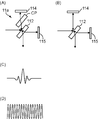
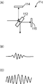
- FIG. 3 shows the configuration of the interferometer in the Fourier transform spectrometer of the first embodiment, the interferometer without the phase compensation plate CP, the interference light waveform (interferogram) of the light to be measured, and the position measurement light source. It is a figure for demonstrating the waveform of the interference light of the laser beam of.
- FIG. 3A shows the configuration of the interferometer in the Fourier transform spectrometer of the first embodiment
- FIG. 3B shows the Michelson interferometer when the phase compensation plate CP for phase compensation is not provided.
- FIG. 3C schematically shows the interference light waveform (interferogram) of the light to be measured
- FIG. 3D schematically shows the position measurement light source.
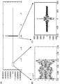
- FIG. 4 is a diagram showing, as an example, the actually measured interference light waveform (interferogram) of the measured light in the Fourier transform spectrometer of the first embodiment.
- 4A shows the whole
- FIG. 4B shows the vicinity of the zero level
- FIG. 4C shows the vicinity of the center burst.
- FIG. 5 is a diagram showing an actually measured interference waveform of laser light from a position measurement light source in the Fourier transform spectrometer of the first embodiment. 5A shows the whole, FIG. 5B shows the vicinity of the end, and FIG. 5C shows the vicinity of the maximum value.
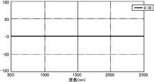
- FIG. 6 is a diagram showing a phase shift that occurs in the semi-transparent mirror.
- FIG. 7 is a diagram showing the phase when the phase shift caused by the semi-transparent mirror is compensated. 6 and FIG. 7, the horizontal axis indicates the wavelength expressed in nm unit, and the vertical axis indicates the phase expressed in degree unit.
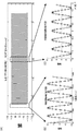
- FIG. 8 is a diagram for explaining a predetermined range to be taken out by the takeout unit in the first embodiment. Each of FIGS. 8A, 8B, and 8C schematically shows each measurement result in each measurement of the first time, the (n-1) th time, and the nth time (n is an integer of 2 or more).
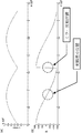
- FIG. 9 is a diagram illustrating the relationship between the interferogram and the window function. The horizontal axis in FIG. 9 indicates the optical path difference, and the vertical axis indicates the amplitude.
- the Fourier transform spectrometer Da takes in the light to be measured emitted from the measurement target object SM.
- the light to be measured enters the interferometer 11 a and is received by the first light receiving unit 21 as interference light of the light to be measured. More specifically, the light to be measured is converted into parallel light by the collimator lens 111 and is reflected and transmitted by the semi-transparent mirror 112 via the beam splitter 33 to be branched into the first and second light to be measured.
- the first light to be measured branched by being reflected by the semi-transparent mirror 112 is incident on the fixed mirror 114 via the phase compensation plate CP, is reflected by the fixed mirror 114, and traces the incoming optical path in the reverse direction, and again returns to the semi-transparent mirror 112.
- the second light to be measured branched by passing through the semi-transparent mirror 112 is incident on the movable mirror 115, reflected by the movable mirror 115, and returns to the semi-transparent mirror 112 by tracing back the optical path that has come.
- the first light to be measured reflected by the fixed mirror 114 and the second light to be measured reflected by the moving mirror 115 are merged with each other by the semi-transparent mirror 112 and interfere with each other.
- the interference light of the light to be measured is emitted from the interferometer 11a to the first light receiving unit 21.
- the first light receiving unit 21 photoelectrically converts the incident interference light of the measurement light, and outputs an electrical signal corresponding to the light intensity in the interference light of the measurement light to the amplification unit 22.
- the amplifying unit 22 amplifies the electric signal corresponding to the interference light of the light to be measured with a predetermined amplification factor, and outputs it to the AD converting unit 23.
- the Fourier transform spectrometer Da also takes in a monochromatic laser beam emitted from the position measuring light source 31a.
- This laser light is incident on the interferometer 11a through the beam splitter 33, interferes with the interferometer 11a in the same manner as described above, and is received by the second light receiving unit 36 through the beam splitter 34 as interference light of the laser light. Is done.
- the second light receiving unit 36 photoelectrically converts the incident interference light of the laser beam, and outputs an electrical signal corresponding to the light intensity in the interference light of the laser beam to the zero cross detection unit 37.
- the zero cross detection unit 37 detects a timing at which the electric signal corresponding to the interference light of the laser beam becomes zero as a zero cross timing, and outputs the zero cross timing to the AD conversion unit 23 as a sampling timing (AD conversion timing).
- the movable mirror 115 of the interferometer 11a is moved along the optical axis direction according to the control of the control calculation unit 41.
- the AD conversion unit 23 samples the electrical signal output from the amplification unit 22 according to the light intensity in the interference light of the light to be measured at the zero cross timing input from the zero cross detection unit 37, and converts the electrical signal from an analog signal to a digital signal. A / D conversion is performed, and the electric signal of the digital signal subjected to the AD conversion is output to the spectrum calculation unit 411 of the control calculation unit 41.
- the light intensity of the interference light of the monochromatic laser light repeatedly increases and decreases in a sine wave shape according to the movement of the movable mirror 115, so that the Fourier transform spectrometer Da Detects the sampling timing of AD conversion by detecting this zero cross timing.
- an interferogram as shown in FIG. 3C and FIG. 4 is input from the AD conversion unit 23 to the spectrum calculation unit 411 of the control calculation unit 41.
- phase compensation in the Fourier transform spectrometer Da of this embodiment will be described.
- the Michelson interferometer without the phase compensation plate CP for phase compensation includes a semi-transparent mirror 112, a fixed mirror 114, and a moving mirror 115 that moves in the optical axis direction.
- the fixed mirror 114 and the movable mirror 115 are arranged so that their optical axes are orthogonal to each other, and the semi-transparent mirror 112 intersects each of these optical axes at an angle of 45 degrees and the intersection position of each of these optical axes. It arrange
- the light to be measured is reflected by the semi-transparent mirror 112 and incident on the fixed mirror 114, reflected by the fixed mirror 114, returned to the semi-transparent mirror 112, and transmitted through the semi-transparent mirror 112.
- the optical path (here, semi-transparent mirror 112 ⁇ fixed mirror 114 ⁇ half-transparent mirror 112) and the semi-transparent mirror 112 are transmitted to enter the movable mirror 115, reflected by the movable mirror 115, and returned to the semi-transparent mirror 112 again.
- Two optical paths are formed as a second optical path to be reflected (here, semi-transparent mirror 112 ⁇ moving mirror 115 ⁇ semi-transparent mirror 112).
- the optical path difference between the two first and second optical paths is zero.
- the merging position interference position
- each of these two first and second optical paths is formed of the same medium is, for example, the case where the first and second optical paths are formed of the same material as the transparent substrate of the semi-transparent mirror 112.
- the semi-transparent mirror 112 when the semi-transparent mirror 112, the fixed mirror 114, and the movable mirror 115 are each disposed in a vacuum or in a gas, and the semi-transparent mirror 112 is formed only by the semi-transparent mirror surface.
- the semi-transparent mirror 112 of the semi-transparent mirror is usually of a negligible thickness.
- the semi-transparent mirror 112 is composed of a transparent substrate formed of a material that is transparent to the wavelength of the light to be measured and the laser beam, such as glass, and one of the transparent substrates. And a semi-transparent surface such as a metal thin film or a dielectric multilayer film formed on the main surface.
- the first measured light in the first optical path does not pass through the transparent substrate of the semi-transparent mirror 112 in the case of merging (interference), but the second in the second optical path.
- the light to be measured passes through the transparent substrate of the semi-transparent mirror 112 twice.
- each of the two first and second optical paths formed by the semi-transparent mirror 112, the fixed mirror 114, and the movable mirror 115 is formed of the same medium between the incident position of the light to be measured and the interference position. Even in the arrangement state in which the semi-transparent mirror 112, the fixed mirror 114, and the movable mirror 115 are arranged so that the optical path difference between the two optical paths becomes zero in the case where the first optical path and the second optical path are The phase difference from the optical path does not become zero due to the refractive index of the transparent substrate.
- the amount of phase shift caused by the transparent substrate of the semi-transparent mirror 112 has a wavelength dependency, as shown in FIG. 6, for example, because the refractive index has a wavelength dependency. is doing.
- each of the two first and second optical paths is temporarily formed of the same medium.
- the semi-transparent mirror 112 the fixed mirror 114, and the movable mirror 115 are arranged so that the optical path difference between the two first and second optical paths becomes zero, Position) between the first measured light branched by the semi-transparent mirror 112 and traveling (propagating) in the first optical path and the second measured light branched by the semi-transparent mirror 112 and advanced through the second optical path.
- phase compensation plate CP having the same phase characteristic (refractive index characteristic) as that of the transparent substrate of the semi-transparent mirror 112 is disposed between the semi-transparent mirror 112 and the fixed mirror 114.
- phase compensation plate CP is the transparent substrate itself of the semi-transparent mirror 112 (of course, there is no semi-transparent mirror surface).
- phase compensation plate CP is used for the phase compensation.
- phase compensation may be performed by a phase compensation calculation devised by Mertz, Forman, or the like.
- a digital signal including an interferogram in which such a center burst is relatively clear is output from the AD conversion unit 23 of the light reception processing unit 20 to the spectrum calculation unit 411a of the control calculation unit 41a. Then, the spectrum calculation unit 411a integrates a plurality of interferograms of such measured light generated by the interferometer 11a in order to improve the SN ratio and obtain a good accuracy result. Generate a ferrogram.
- the sampling count number is reset to 0 at the start of measurement in each of a plurality of measurements, and if the movable mirror 115 always moves in the same manner, the sampling count number A center burst always appears with the same numerical value (same measurement point number), and measurement data with the same sampling count number (same measurement point number) becomes measurement data with the same optical path difference.
- a range i centered on the position of the optical path difference 0 (center burst position) is set as a predetermined range extracted by the extraction unit 4111. In each measurement, the range i is determined from the output of the interferometer 11a. Each time, the measurement data at each sampling point is taken out. This range i is expressed, for example, by Equation 1, where I 0 is the position of the optical path difference 0 (center burst position) and nh is the number of measurement points to be extracted.
- the entire interferogram is completely included in each of the measurement data sets in the retrieved range i, and the measurement data having the same sampling count number (same measurement point number) is It becomes the measurement data of the same optical path difference.
- an integrated interferogram can be generated by adding together the measurement data having the same sampling count for each measurement data set extracted by the extraction unit 4111 in this way.
- the movable mirror 115 is an element that generates an optical path difference between the first and second optical paths by using resonance vibration.
- the amplitude will fluctuate.
- the center burst does not always appear at the same sampling count. Therefore, in each measurement, when measurement data at each sampling point is extracted from the output of the interferometer 11a in the same range i every time, each measurement data set in the extracted range i includes a center burst. There may be cases where only a part of the center burst is included, or those where the center burst is not included at all.
- the extraction unit 4111 of the present embodiment when extracting measurement data of the predetermined range i from the output of the interferometer 11a, measures the measured light before the measurement of the interferogram of the current measured light.
- the predetermined range i to be extracted is set in accordance with the alignment information of the center burst in the interferogram, and measurement data in the predetermined range i is extracted from the output of the interferometer 11a. More specifically, when the extraction unit 4111 of the present embodiment extracts measurement data within a predetermined range i from the output of the interferometer 11a, the extraction unit 4111 and the center burst position of the interferogram in the first measurement and the interface in the previous measurement are used.
- the predetermined range i to be extracted this time (currently) is set by shifting the start position of the predetermined range i to be extracted this time according to the amount of deviation from the center burst position of the ferrogram, and this setting is made from the output of the interferometer 11a.
- the measured data in the predetermined range i is extracted. That is, the position of the optical path difference 0 in the first measurement and the number of data points to be extracted are I 0 and nh, respectively, and the number of data points to be extracted in the n-th measurement is (nh + nr).
- the predetermined range i is In the (n-1) th measurement, the predetermined range i is expressed by the following equation 2 (see FIG. 8B), and In the n-th measurement, the predetermined range i is expressed by the following equation 3 (see FIG. 8C).
- the search unit 4112 finds measurement data having the same optical path difference in each measurement data set extracted by the extraction unit 4111.
- the search unit 4112 has the measurement data set extracted by the extraction unit 4111 in the first measurement and the measurement data extracted by the extraction unit 4111 in the n-th measurement (n is an integer of 2 or more).
- the measurement data of the same optical path difference is found by obtaining the maximum value of the cross-correlation in the set. More specifically, the search unit 4112 first sets the sampling count number (measurement point number) to i, sets the measurement data set extracted by the extraction unit 4111 in the first measurement to Intergram 1 (i), and sets the nth time.
- the search unit 4112 finds the maximum value k of the cross-correlation function ⁇ (k). Then, the search unit 4112 receives the measurement data set Interferogram n ((n) obtained by the extraction unit 4111 in the n-th measurement (n is an integer of 2 or more) by the shift amount k 0 (n) obtained by the following equation 4-2.
- the measurement data of the same optical path difference is found by shifting the measurement point number of i). That is, the measurement data of the measurement point number j (j ⁇ i) in the measurement data set Interferogram 1 (i) extracted by the extraction unit 4111 in the first measurement and the measurement extracted by the extraction unit 4111 in the n-th measurement.
- the measurement data of the measurement point number j + k 0 (n) in the data set Interferogram n (i) is the measurement data of the same optical path difference.
- the search unit 4112 may measure the measurement data set Interferogram 1 (i) extracted by the extraction unit 4111 in the first measurement and the measurement extracted by the extraction unit 4111 in the n-th measurement (n is an integer of 2 or more).
- the measurement data of the same optical path difference may be found by obtaining the minimum value in the sum of the squares of the differences for the measurement points.
- the search unit 4112 first shifts the value of k sequentially within a range of 0 ⁇ k ⁇ (nr ⁇ 1), while calculating the square sum ⁇ 2 of the difference between the nh points by the following equation 5-1.
- the search unit 4112 receives the measurement data set Interferogram n ((n) obtained by the extraction unit 4111 in the n-th measurement (n is an integer of 2 or more) by the shift amount k 0 (n) obtained by the following equation 5-2.
- the measurement data of the same optical path difference is found by shifting the measurement point number of i).
- the search unit 4112 may measure the measurement data set Interferogram 1 (i) extracted by the extraction unit 4111 in the first measurement and the measurement extracted by the extraction unit 4111 in the n-th measurement (n is an integer of 2 or more).
- the measurement data of the same optical path difference may be found by obtaining the minimum value in the sum of the absolute values of the differences for the measurement points.
- the search unit 4112 first shifts the value of k sequentially in the range of 0 ⁇ k ⁇ (nr ⁇ 1), and then calculates the sum of the absolute values of the differences between the nh points by the following equation 6-1: A (k) is obtained, and the minimum value k of the sum ⁇ A (k) of the absolute values of the differences is found. Then, the search unit 4112 receives the measurement data set Interferogram n ((n)) obtained by the extraction unit 4111 in the n-th measurement (n is an integer of 2 or more) by the shift amount k 0 (n) obtained by the following equation 6-2. The measurement data of the same optical path difference is found by shifting the measurement point number of i).
- the search range may be expanded according to the previous shift amount k 0 (n ⁇ 1).
- the data used for alignment in the n-th measurement data set Interferogram n (i) is [(I 0 + k 0 (n ⁇ 1) ⁇ (nh + nr) / 2) ⁇ i ⁇ (I 0 + (nh + nr) / 2)] in the range (nh + nr ⁇ k 0 (n ⁇ 1)) point data is used, and when k 0 (n ⁇ 1)> 0
- [(I 0 ⁇ (nh + nr) / 2) ⁇ i ⁇ (I 0 + k 0 (n ⁇ 1) ⁇ (nh + nr) / 2) ] (Nh + nr ⁇ k 0 (n ⁇ 1)) point data is used.
- the integration unit 4113 uses the same optical path found by the search unit 4112 in each measurement data set extracted by the extraction unit 4111.
- An integrated interferogram is generated by adding the difference measurement data together.
- the optical path difference is x i
- the wave number is ⁇ j
- the spectrum amplitude of the wave number ⁇ j is B ( ⁇ j ).
- the optical path difference 0 position is X 0
- the phase of the wave number ⁇ j at the optical path difference 0 position is ⁇ ( ⁇ j )
- m represents the measurement result of the mth measurement.
- Equation 8 the integrated interferogram F (x i ) is expressed by Equation 8.
- the calculation unit 4114a obtains the spectrum of the light to be measured by performing, for example, fast Fourier transform (FFT) on the integration interferogram generated by the integration unit 4113. .
- FFT fast Fourier transform
- the window function A window (x i ) can include various appropriate functions.
- the window function A window (x i ) is a function represented by Expression 11-1 to Expression 11-3. Equations 11-1 and 11-2 are called Hamming Window functions, and Equation 11-3 is called a Blackman Window function.
- the spectrum calculation unit 411a generates an integrated interferogram by integrating a plurality of interferograms of the measured light obtained by the interferometer 11a, and the generated integrated interferogram
- the spectrum of the light to be measured is obtained by Fourier transform.
- the obtained spectrum of the light to be measured is output to the output unit 43.
- the predetermined range to be extracted is taken out.
- i is set according to the alignment information of the center burst in the interferogram of the measured light before the measurement of the interferogram of the current measured light.
- the center burst position of the interferogram in the first measurement and the interferometer in the previous measurement are used as the alignment information.
- the shift amount k 0 (n ⁇ 1) from the center burst position of the gram is used.
- the Fourier transform spectrometer Da according to the present embodiment and the Fourier transform spectroscopic method implemented in the Fourier transform spectrometer Da are offset between the interferogram measured immediately before this time and the interferogram measured this time. It is possible to cope with the case where k 0 (n ⁇ 1) is small, and it is possible to more appropriately extract measurement data in a range that completely includes the entire interferogram. Can be accumulated.
- the Fourier transform spectrometer Da of this embodiment and the Fourier transform spectroscopic method implemented therein when finding the measurement data of the same optical path difference by cross-correlation, the measurement data of the same optical path difference is more accurately obtained. You can find out. For this reason, the Fourier transform spectrometer Da of the present embodiment and the Fourier transform spectroscopic method mounted thereon can suitably integrate a plurality of interferograms.
- the Fourier transform spectrometer Da of the present embodiment and the Fourier transform spectroscopic method mounted thereon when finding the measurement data of the same optical path difference by the sum of the squares of the differences, the same optical path difference is more accurately detected. The measurement data can be found. For this reason, the Fourier transform spectrometer Da of the present embodiment and the Fourier transform spectroscopic method mounted thereon can suitably integrate a plurality of interferograms.
- the Fourier transform spectrometer Db according to the second embodiment is mounted on a device capable of detecting a minute signal near the zero level of the interferogram with higher resolution even with a single AD converter. This is a Fourier transform type spectroscopic method.
- FIG. 10 is a block diagram showing the configuration of the Fourier transform spectrometer in the second embodiment.
- FIG. 11 is a diagram mainly illustrating a configuration of an interferometer in the Fourier transform spectrometer according to the second embodiment.
- FIG. 12 is a diagram illustrating a spectrum of laser light emitted from a position measurement light source in the Fourier transform spectrometer according to the second embodiment. The horizontal axis in FIG. 12 is the wave number (1 / wavelength), and the vertical axis is the magnitude of the amplitude.
- FIG. 13 is a circuit diagram showing a configuration of an envelope detector in the Fourier transform spectrometer of the second embodiment.
- the Fourier transform spectrometer Db Similar to the Fourier transform interferometer Da according to the first embodiment, the Fourier transform spectrometer Db according to the second embodiment measures the measured light to be measured with the interferometer, and integrates the measured measured light. This is a device for obtaining a spectrum of measured light by Fourier transforming an interferogram. For example, as shown in FIG. 10 and FIG. 11, the Fourier transform spectrometer Db receives light (measurement light) emitted from the measurement target object SM and emits interference light of the measurement light.
- the interferometer 11b that receives the interference light of the light to be measured obtained by the interferometer 11b, and an electric signal of the waveform of the interference light of the light to be measured by photoelectric conversion (represents a change in light intensity in the interference light of the light to be measured)
- a light reception processing unit 20 that outputs an electrical signal
- a position detection processing unit 30b that detects the position of the movable mirror 115 of the interferometer 11b
- a control calculation unit 41b that an input unit 42, and an output unit 43.
- the light receiving processing unit 20, the input unit 42, and the output unit 43 in the second embodiment are the same as the light receiving processing unit 20, the input unit 42, and the output unit 43 in the first embodiment, respectively, and thus description thereof is omitted. .
- the interferometer 11b receives measurement light to be measured, branches the incident measurement light into two first and second measurement lights, Each of the branched first and second light beams to be measured travels (propagates) to the first and second optical paths, which are two different paths, and merges again.
- This branch point (branch) If there is an optical path difference between the first and second optical paths from the position) to the merging point (merging position, interference position), a phase difference is generated at the time of merging. Is.
- the interferometer 11b is configured such that when each of the two first and second optical paths is formed of the same medium, the optical path difference between the two first and second optical paths.
- phase difference interferometer having a phase difference between the first and second optical paths actually It is.
- Such an interferometer 11b will be described using, for example, a Michelson interferometer.
- a semi-transparent mirror 112 and a fixed mirror are arranged as in the case of the above-described interferometer 11a shown in FIG.
- the first phase difference plate 113 is further provided on the transmission side of the semi-transparent mirror 112 that transmits the first phase difference plate. That is, in the present embodiment, the second measured light that has passed through the semi-transparent mirror 112 is incident on the movable mirror 115 via the first phase difference plate 113, and the second measured light that is reflected by the movable mirror 115 is The light enters the semi-transparent mirror 112 again through the first retardation plate 113.
- the semi-transparent mirror 112, the fixed mirror 114, and the movable mirror 115 in the interferometer 11b of the second embodiment are the same as the semi-transparent mirror 112, the fixed mirror 114, and the movable mirror 115 in the interferometer 11a of the first embodiment, respectively. The description is omitted.
- the first phase difference plate 113 is an isotropic phase plate, and the first phase difference plate 113 with respect to the phase of light traveling in the vacuum or in air for the same distance as the thickness of the first phase difference plate 113. This causes a shift in the phase of the light traveling inside.
- the Fourier transform spectrometer Db of the second embodiment includes the first phase difference plate 113 without the phase compensation plate CP unlike the interferometer 11a of the Fourier transform spectrometer Da of the first embodiment. I have.
- the Fourier transform spectrometer Db of this embodiment also includes, for example, a collimator lens 111 as an incident optical system and, for example, a condenser lens 116 as an exit optical system, which are respectively provided with the Fourier transform spectrometer of the first embodiment. Since this is the same as the collimator lens 111 and the condenser lens 116 in the total Da, the description thereof is omitted.
- the position detection processing unit 30b includes, for example, a position measurement light source 31b, a second light receiving unit 36, a zero-cross detection unit 37, and an envelope detection unit 38. Then, the position detection processing unit 30b obtains the interference light of the laser light emitted from the position measurement light source 31b with the interferometer 11b, as shown in FIG. 11, a collimator lens 32, a beam splitter 33, A beam splitter 34 and a condenser lens 35 are further provided. That is, the Fourier transform spectrometer Db of the second embodiment is provided with a position measurement light source 31b instead of the position measurement light source 31a with respect to the Fourier transform spectrometer Da of the first embodiment, and further includes an envelope detector. 38.
- the second light receiving unit 36, the zero cross detection unit 37, the collimator lens 32, the beam splitter 33, the beam splitter 34, and the condenser lens 35 in the Fourier transform spectrometer Db of the second embodiment are respectively the first embodiment. Since this is the same as the second light receiving unit 36, the zero cross detection unit 37, the collimator lens 32, the beam splitter 33, the beam splitter 34, and the condensing lens 35 in the Fourier transform spectrometer Da, the description thereof is omitted.
- the collimator lens 32, the beam splitter 33, the beam splitter 34, and the condenser lens 35 are arranged in the same manner as in the case of the interferometer 11a shown in FIG.
- the position measuring light source 31b is a light source device that emits laser light having a predetermined line width set in advance.
- the position measuring light source 31b includes, for example, a semiconductor laser that emits laser light having a predetermined line width. Further, for example, the position measuring light source 31b includes a laser device that emits monochromatic laser light, and a high-frequency superimposing device that superimposes the monochromatic laser light emitted from the laser device at a high frequency. A laser beam having a predetermined line width is emitted.
- the predetermined line width is a wavelength width (frequency width) such that the amplitude of the interference light of the laser light obtained by the interferometer 11b changes according to the movement of the movable mirror 115 of the interferometer 11b.
- the magnitude of the amplitude of the interference beam of the laser beam is that of the interferometer 11a. It does not change with the movement of the movable mirror 115.
- a Gaussian profile having a full width at half maximum (FWHM) of 2.3 / cm with respect to a center wave number of 15151.52 / cm. have.
- the laser light emitted from the position measuring light source 11b is incident on the interferometer 11b, and the interference light of the laser light is received by the second light receiving unit 36.
- the second light receiving unit 36 outputs an electrical signal corresponding to the light intensity of the interference light of the laser light to each of the zero cross detection unit 37 and the envelope detection unit 38.
- the envelope detector 38 is a circuit that detects an envelope of an electric signal input from the second light receiver 36 and corresponding to the light intensity of the interference light of the laser beam.
- the envelope detector 38 can employ various circuit configurations. For example, as shown in FIG. 13, the envelope detector 38 is connected in series with the diode D by being connected to the diode D and the cathode terminal of the diode D.
- the resistor element R is connected to the resistor element R, and the capacitor C is connected in parallel to the resistor element R. Both ends of the series-connected diode D and the resistor element R are input ends, and both ends of the resistor element R are The output end.
- the envelope detector 38 can detect the envelope with such a simple circuit configuration.
- the envelope detection unit 38 outputs an envelope of an electric signal corresponding to the detected light intensity of the interference light of the laser beam to the control calculation unit 41.
- the control calculation unit 41b controls each part of the Fourier transform spectrometer Db according to the function of each part in order to obtain the spectrum of the light to be measured.
- the control calculation unit 41b functionally includes a spectrum calculation unit 411b and a center burst position calculation unit 412 by executing a program.
- the spectrum calculation unit 411b obtains the spectrum of the light to be measured by Fourier-transforming an integrated interferogram obtained by integrating a plurality of interferograms of the light to be measured generated by the interferometer 11b. is there.
- the spectrum calculation unit 411b is functionally configured with an extraction unit 4111, a search unit 4112, an integration unit 4113, and a calculation unit 4114b by executing a program. That is, the spectrum calculation unit 411b in the Fourier transform spectrometer Db of the second embodiment is different from the spectrum calculation unit 411a in the Fourier transform spectrometer Da of the first embodiment in that the calculation unit 4114b functions instead of the calculation unit 4114a. Constructed.
- the extraction unit 4111, the search unit 4112, and the integration unit 4113 of the spectrum calculation unit 411b in the Fourier transform spectrometer Db of the second embodiment are respectively the spectrum calculation unit 411b of the Fourier transform spectrometer Da of the first embodiment. Since it is the same as the extraction unit 4111, the search unit 4112, and the integration unit 4113, description thereof is omitted.
- the calculation unit 4114b obtains the spectrum of the measured light by performing a Fourier transform on the integration interferogram generated by the integration unit 4113 based on the position of the center burst detected by the center burst position calculation unit 412. is there.
- the center burst position calculation unit 412 detects the position of the center burst in the interferogram when the initial phase difference of each wavelength component of the light under measurement is zero. More specifically, in this embodiment, the center burst position calculation unit 412 detects a position that gives the maximum value of the envelope detected by the envelope detection unit 38 as the position of the center burst. As described above, in the present embodiment, the position of the center burst detects the envelope of the light intensity in the interference light of the laser light obtained by making the laser light having a predetermined line width enter the interferometer 11b, It is obtained by detecting the position giving the maximum value of the detected envelope.
- FIG. 14 is a diagram for explaining the configuration of the interferometer in the Fourier transform spectrometer of the second embodiment, the waveform (interferogram) of the interference light of the light to be measured, and the waveform of the interference light of the laser light of the position measurement light source.
- FIG. FIG. 14A shows the configuration of the interferometer in the Fourier transform spectrometer according to the second embodiment
- FIG. 14B schematically shows the waveform of the interference light of the measured light (interferogram).
- FIG. 14C schematically shows the waveform of the interference light of the laser beam of the position measurement light source, which is schematically drawn.
- FIG. 15 is a diagram showing, as an example, a waveform (interferogram) of measured interference light of measured light in the Fourier transform spectrometer of the second embodiment.
- FIG. 15A shows the whole
- FIG. 15B shows the vicinity of the zero level
- FIG. 15C shows the vicinity of the center burst.
- FIG. 16 is a diagram showing an actually measured interference waveform of laser light from a position measurement light source in the Fourier transform spectrometer of the second embodiment as an example. 16A shows the whole, FIG. 16B shows the vicinity of the end, and FIG. 16C shows the vicinity of the maximum value.
- FIG. 17 is a diagram for explaining a predetermined range to be taken out by the takeout unit in the second embodiment.
- FIGS. 17A, 17B, and 17C schematically shows each measurement result in each measurement of the first time, the (n-1) th time, and the nth time (n is an integer of 2 or more).
- the Fourier transform spectrometer Db takes in the measurement light emitted from the measurement object SM.
- the light to be measured is incident on the interferometer 11b and is received by the first light receiving unit 21 as interference light of the light to be measured, as in the case of the interferometer 11a of the Fourier transform spectrometer Da of the first embodiment.
- the in the interferometer 11b in the Fourier spectrometer Db of the second embodiment the first measured light passes through the phase compensation plate CP, as in the interferometer 11a in the Fourier transform spectrometer Da of the first embodiment.
- the second measured light passes through the first retardation plate 113.
- the Fourier transform spectrometer Db is an optical element made of, for example, a transparent substrate in at least one of the optical paths so that the number of refractions of the light passing through the two first and second optical paths is different.
- a first retardation plate 113 is provided (see FIG. 11).
- the first light receiving unit 21 photoelectrically converts the incident interference light of the light to be measured and outputs an output electric signal to the amplifying unit 22, and the amplifying unit 22 amplifies the electric signal, and AD The data is output to the conversion unit 23.
- the Fourier transform spectrometer Db also captures laser light having a predetermined half width emitted from the position measurement light source 31b.
- This laser light is incident on the interferometer 11b through the beam splitter 33, interferes with the interferometer 11b in the same manner as described above, and is received by the second light receiving unit 36 through the beam splitter 34 as interference light of the laser light. Is done.
- the second light receiving unit 36 photoelectrically converts the incident interference light of the laser beam and outputs the output electric signal to the zero cross detection unit 37 and the envelope detection unit 38, respectively.
- the zero cross detector 37 detects the zero cross timing of the electrical signal and outputs it to the AD converter 23.
- the movable mirror 115 of the interferometer 11b is moved along the optical axis direction under the control of the control calculation unit 41b.
- the AD conversion unit 23 samples the electric signal from the amplification unit 22 at the zero cross timing from the zero cross detection unit 37 and performs AD conversion from an analog signal to a digital signal.
- the AD conversion unit 23 controls the electric signal of the AD converted digital signal. It outputs to the spectrum calculating part 411b of the calculating part 41b.
- an interferogram as shown in FIG. 14B and FIG. 15 is input from the AD conversion unit 23 to the spectrum calculation unit 411b of the control calculation unit 41b.
- the interferogram generated by the Fourier transform spectrometer Da of the first embodiment compensated by the phase compensation plate CP. This will be explained in comparison with
- the Fourier transform spectrometer Da according to the first embodiment since the Fourier transform spectrometer Da according to the first embodiment includes the phase compensation plate CP as described above and is phase-compensated, the Fourier transform spectrometer Da according to the first embodiment uses the light to be measured. In the interferogram of the interference light, the initial phase difference of each wavelength component of the light to be measured becomes zero, the center burst is relatively clear and large as shown in FIG. 3C and FIG. Becomes a small profile.
- the Fourier transform spectrometer Db of the second embodiment does not include the phase compensation plate CP, and further includes the phase difference plate 113 only in the second optical path.
- the interferometer 11b according to the second embodiment includes a plurality of optical elements (in the example shown in FIG. 10, the semi-transparent mirror 112, the fixed mirror 114, and the movable mirror 115) between the incident position of the light to be measured and the interference position.
- the two first and second optical paths are formed, and each of the two first and second optical paths is formed of the same medium, between the two first and second optical paths
- the phase difference interferometer having a phase difference between the optical paths in the arrangement state in which the plurality of optical elements are arranged so that the optical path difference of the optical path becomes zero.
- the phase difference interferometer is in an arrangement state in which the movable mirror 114 is located at the center burst position when the phase compensation is performed like the interferometer 11a having the phase compensation plate CP.
- the interferometer 11b is a phase difference interferometer, and as an example, as can be understood from a comparison between FIG. 4 and FIG. 15, the interferometer 11b includes the phase compensation plate CP.
- the magnitude (level) of the amplitude is small. For example, as shown in FIG.
- the maximum amplitude Y in the interferogram by the interferometer 11a having the phase compensation plate CP is about 3200, but by the interferometer 11b of the second embodiment.
- the maximum amplitude magnitude X in the interferogram is about 1400 (X ⁇ Y) as shown in FIG.
- the A / D count assigned to one unit amplitude level is higher in the Fourier transform spectrometer Db of the second embodiment. More than the Fourier transform spectrometer Da of one embodiment. That is, the maximum amplitude at one or more peaks of the interferogram in the Fourier transform spectrometer Db of the second embodiment is X, and one or more of the interferograms in the Fourier transform spectrometer Da of the first embodiment.
- the Fourier transform spectrometer Db of the second embodiment has a relatively larger A / D count for the electrical signal near the zero level than the Fourier transform spectrometer Da of the first embodiment. Assigned (2 Z / X> 2 Z / Y). Therefore, the Fourier transform spectrometer Db of the second embodiment can detect a minute signal near the zero level of the interferogram with higher resolution even with a single AD converter.
- the Fourier transform spectrometer Db of the second embodiment as described above, a phase difference interferometer is used as the interferometer 11b.
- a phase difference interferometer is used as the interferometer 11b.
- the position of the center burst is unclear. Accordingly, the Fourier transform spectrometer Db of the second embodiment obtains the position of the center burst from the envelope in the interference light of the laser light having a predetermined line width.
- a monochromatic laser beam is used in order to obtain the AD conversion sampling timing by detecting the movement position of the movable mirror 115 in the interferometer 11a. It is used. As shown in FIGS. 5A, 5B, and 5C, the light intensity of the interference light of the monochromatic laser light has a substantially constant amplitude at both the position of the optical path difference 0 and the position of the sideband. The position of the optical path difference 0 corresponds to the position of the center burst in the interferogram when the initial phase difference of each wavelength component of the light under measurement is zero.
- a laser beam having a predetermined line width is used instead of the monochromatic laser beam.
- the interference light of the laser light having such a predetermined line width has the same zero-cross timing as that of the monochromatic laser light, but FIGS. 16A, 16B, and 16C. ).
- the amplitude is the largest at the position where the optical path difference is 0, and the amplitude gradually decreases as the position approaches the sideband position. Therefore, the position of the center burst can be detected by detecting the envelope of the light intensity in the interference light of the laser light having a predetermined line width.
- the envelope detector 38 envelope-detects an electric signal according to the light intensity in the interference light of the laser beam input from the second light receiver 36, and the result is a control calculation unit 41b.
- the center burst position calculation unit 412 detects the maximum value of the envelope input from the envelope detection unit 38, and obtains the position that gives this maximum value as the position of the center burst. Then, the center burst position calculation unit 412 outputs the obtained center burst position to the spectrum calculation unit 411.
- the interferogram of the light to be measured is input from the AD conversion unit 23 and the center burst position is input from the center burst position calculation unit 412 to the spectrum calculation unit 411b.
- the spectrum calculation unit 411b generates an integration interferogram by the extraction unit 4111, the search unit 4112, and the integration unit 4113 by the same operation as in the first embodiment, and detects the integration interferogram of this measured light. Based on the position of the center burst, Fourier transform, for example, fast Fourier transform is performed to obtain the spectrum of the light to be measured. More specifically, when the extraction unit 4111 extracts the measurement data of the predetermined range i from the output of the interferometer 11b, for example, in the first measurement, the predetermined range i is expressed by the above formula 1 (FIG. 17 ( (See A)), in the (n-1) th measurement, the predetermined range i is expressed by the above equation 2 (see FIG.
- the predetermined range i is expressed by the above equation 3
- the predetermined range i to be extracted this time is expanded in accordance with the number of times of measurement with respect to the range extracted in the first measurement, and the interfero in the first measurement is expanded.
- This time is taken out by shifting the start position of the predetermined range i to be taken this time according to the amount of deviation between the center burst position of the gram and the center burst position of the interferogram in the previous measurement.
- Set the range i retrieving the measured data in a predetermined range i that this setting from the output of the interferometer 11b.
- the search unit 4112 uses, for example, the above expression 4 (expression 4-1 and expression 4-2) to expression 6 (expression 6-1 and expression 6-2) in each measurement data set extracted by the extraction unit 4111.
- the measurement data of the same optical path difference is found by the above-described method using any one of the above.
- the integration unit 4113 generates an integration interferogram by adding together the measurement data of the same optical path difference found by the search unit 4112 in each measurement data set extracted by the extraction unit 4111.
- the arithmetic unit 4114b performs fast Fourier transform on the integrated interferogram of the light under measurement based on the position of the detected center burst according to the above formulas 8 to 10, and calculates the spectrum of the light under measurement. Ask.
- the obtained spectrum of the light to be measured is output to the output unit 43.
- the optical elements constituting the interferometer 11b are arranged at a virtual optical path difference of zero. Even if the interference light of the light to be measured is generated by the interferometer 11b which is a phase difference interferometer having a phase difference, the maximum amplitude X at one or a plurality of peaks of the interferogram is equal to the phase. It becomes smaller than the maximum amplitude Y at one or more peaks of the interferogram corresponding to the interference light of the measured light generated by the compensated interferometer 11a (X ⁇ Y).
- the Fourier transform spectrometer Db and the Fourier transform spectroscopic method implemented in the second embodiment have a single AD converter near the zero level of the interferogram when the AD converter is used. Small signals can be detected with higher resolution.
- the Fourier transform spectrometer Db of the second embodiment satisfies X ⁇ Y as described above, an operational amplifier having a relatively low slew rate (relative to the input signal) is used as the amplifier of the amplification unit 22.
- a slow operational amplifier and a low noise amplifier.
- LNA low noise amplifier
- the Fourier transform spectrometer Db of the second embodiment further includes the first phase difference plate 113 on the transmission side of the semi-transparent mirror 112, the phase difference between the first and second optical paths in the interferometer 11 is further increased. can do.
- the Fourier transform spectrometer Db of the present embodiment does not include the first phase difference plate 113 shown in FIG. 18A described later with the maximum amplitude X at one or more peaks of the interferogram.
- the interferogram can be made smaller than the interferogram obtained by the phase difference interferometer having only the phase difference generated on the transparent substrate of the semi-transparent mirror 112.
- the Fourier transform spectrometer Db of the second embodiment detects the position of the center burst by detecting the envelope of the light intensity in the interference light of the laser light having a predetermined line width, for example, FIG.
- the detector circuit can be configured with a simpler circuit configuration as shown in FIG.
- the Fourier transform spectrometer Db of the second embodiment is configured such that the laser beam is a laser beam having a predetermined line width, and detects the position of the movable mirror 112 as a configuration for detecting the position of the center burst. A part of the structure is diverted. More specifically, the configuration from the position measurement light source 31 b to the second light receiving unit 36 is shared, and the output of the second light receiving unit 36 is output to each of the zero cross detection unit 37 and the envelope detection unit 38. For this reason, the Fourier transform spectrometer Db of the second embodiment can detect the position of the center burst with a smaller circuit configuration.
- the position measurement light source 31b a laser device that emits laser light having a predetermined line width by superimposing monochromatic laser light at high frequency, or a predetermined line A semiconductor laser that emits laser light having a width is used. For this reason, in the second embodiment, a position measurement light source 31b that emits laser light having the predetermined line width can be configured more simply.
- FIG. 18 shows the configuration of the interferometer of the second aspect in the Fourier transform spectrometer of the second embodiment, the waveform (interferogram) of the interference light of the light to be measured, and the waveform of the interference light of the laser light of the position measurement light source. It is a figure for demonstrating.
- FIG. 18A shows the configuration of the interferometer of the second mode in the Fourier transform spectrometer of the second embodiment, and FIG. 18B schematically shows the waveform of the interference light of the measured light. (Interferogram) is shown, and FIG. 18C schematically shows the waveform of the interference light of the laser light of the position measurement light source, which is schematically drawn.
- FIG. 19 is a diagram illustrating a configuration of the interferometer of the third aspect in the Fourier transform spectrometer according to the second embodiment.
- an interferometer 11b having a phase difference plate 113 between a semi-transparent mirror 112 and a movable mirror 115 is used as a phase difference interferometer.
- Interferometer 11b of the first aspect in the second embodiment is used, but is not limited to this.
- the interferometer 11d of the third aspect in the second embodiment having the configuration shown in FIG. 19 may be used.
- the interferometer 11c of the second aspect has a phase difference because the semi-transparent mirror 112 includes a transparent substrate, and therefore, the interferometer 11c shown in FIG.
- the structure except the phase difference plate 113 in the interferometer 11b of the said 1st aspect As described above, in the Michelson interferometer having a very general configuration using the normal semi-transparent mirror 112 including the transparent substrate having the semi-transparent surface formed on one main surface, the phase compensation described above with reference to FIG. By not providing the phase compensation plate CP for performing the above, the phase difference interferometer can be easily configured. That is, as shown in FIG.
- the interferometer 11c includes a semi-transparent mirror 112, a fixed mirror 114, and a movable mirror 115 that moves in the optical axis direction.
- the light is branched into two first and second light beams to be measured and incident on the fixed mirror 114 and the movable mirror 115, respectively.
- the first light beam to be measured reflected by the fixed mirror 114 and the second light beam reflected by the movable mirror 115, respectively.
- a Michelson interferometer that causes measurement light to interfere with each other with a semi-transparent mirror 112, and the semi-transparent mirror 112 includes a transparent substrate and a semi-transparent surface formed on one main surface of the transparent substrate. is there.
- the interferometer 11c according to the second aspect also has the same operational effects as the interferometer 11b according to the first aspect.
- FIGS. 14 (B) and (C) and FIGS. 18 (B) and (C) In order to further include the phase difference plate 113, the interferometer 11b of the first aspect has a smaller maximum amplitude in the interference light of the measured light than the interferometer 11c of the second aspect. Also, the amplitude change of the envelope in the interference light of the laser beam is large. For this reason, when comparing the interferometer 11b of the first aspect with the interferometer 11c of the second aspect, the interferometer 11b of the first aspect is more advantageous.
- the interferometer 11d of the third aspect includes a semi-transparent mirror 112, a fixed mirror 114, and a movable mirror 115 that moves in the optical axis direction.
- the light is branched into two first and second light beams to be measured and incident on the fixed mirror 114 and the movable mirror 115, respectively.
- a Michelson interferometer that causes measurement light to interfere with each other by a semi-transparent mirror 112, and the semi-transparent mirror 112 includes a transparent substrate and a semi-transparent surface formed on one main surface of the transparent substrate.
- the interferometer 11d reflects the reflected light of the half mirror 112 reflected by the half mirror 112 when the light to be measured is split into two first and second measured lights by the half mirror 112.
- a second phase difference plate 117 is further provided on the side, and the second phase difference plate 117 generates a phase difference different from the phase difference generated in the semi-transparent mirror 112.
- the second retardation plate 117 is formed of a material having the same thickness as the transparent substrate of the semi-transparent mirror 112 and a different refractive index (refractive index characteristic) from the transparent substrate of the semi-transparent mirror 112, for example.
- the second retardation plate 117 has a thickness different from that of the transparent substrate of the semi-transparent mirror 112 by a material (for example, the same material) having the same refractive index (refractive index characteristic) as that of the transparent substrate of the semi-transparent mirror 112. Is formed.
- Such an interferometer 11d of the third aspect further includes a second retardation plate 117 on the reflection side of the semi-transparent mirror 112, so that it is compared with the interferometer 11c of the second aspect having the configuration shown in FIG.
- the phase difference between the first and second optical paths can be further increased.
- the second phase plate 117 is further provided, and the interferometer 11e of the fourth mode in the second embodiment (not shown). May be configured.
- FIG. 20 is a diagram for explaining a second mode method for obtaining the position of the center burst based on the envelope in the interference light of the laser beam.
- FIG. 20A shows the envelope
- FIG. 20B shows a differential waveform of the envelope.
- FIG. 21 is a diagram for explaining the method of the third aspect for obtaining the position of the center burst based on the envelope in the interference light of the laser light. 20 and FIG. 21, the horizontal axis indicates the optical path difference (position of the movable mirror 115), and the vertical axis indicates the level.
- the center burst position calculation unit 412 calculates the maximum value of the envelope input from the envelope detection unit 38 according to the movement of the movable mirror 112 (change in optical path difference).
- the detection may be performed at a point where the amplitude value (level) has changed from an increase to a decrease.
- the amplitude value level
- FIG. 20A when the envelope is in the vicinity of the maximum value, the movement of the movable mirror 112 (optical path difference) If the point changes relatively slowly according to the change of the above, it is not easy to detect the point with high accuracy.
- the center burst position calculation unit 412 determines the position that gives the maximum value of the envelope detected by the envelope detection unit 38 based on the difference information of the envelope detected by the envelope detection unit 38 as the position of the center burst. You may detect as.
- the center burst position calculation unit 412 obtains a difference between two points on the envelope at an appropriate interval. For example, when the difference between two points on the envelope is obtained for the envelope shown in FIG. 20A, a difference graph shown in FIG. 20B is obtained as the difference information. In the difference graph, since the zero cross point at which the difference value changes from a positive value to a negative value corresponds to the position where the maximum value is given, the center burst position calculation unit 412 determines that the difference value is from the positive value in the difference graph. A zero cross point that turns to a negative value is obtained, and the zero cross point may be set as the center burst position.
- the larger the interval for obtaining the difference the larger the difference value, and the zero cross point can be detected with higher accuracy.
- the position of the center burst can be detected with higher accuracy.
- the difference when obtaining such a difference, the storage capacity of the storage element that stores the measurement result of the envelope is restricted, and the interval cannot be made too large, or the number of bits Z of the AD conversion unit 23 is small and the resolution is small.
- the difference may have a stepped shape near the zero cross point, as shown in FIG. In such a case, the position of the center burst may be obtained by linearly approximating the difference graph near the zero cross point by the least square method and obtaining the zero cross point of the approximate straight line.
- the center burst position calculation unit 412 in the Fourier transform spectrometer Db of the second embodiment can more accurately detect the position that gives the maximum value of the envelope. Even if it is difficult to distinguish the maximum value of the envelope because the change of the envelope is gentle, it is possible to detect the position where the maximum value of the envelope is given.
- a Fourier transform spectrometer includes a plurality of optical elements that receive measurement light to be measured and form two optical paths between an incident position of the measurement light and an interference position, In the plurality of optical elements, an interferometer including an optical path difference forming optical element that generates an optical path difference between the two optical paths and a plurality of interferograms of the light to be measured generated by the interferometer are integrated.
- a spectrum calculation unit that obtains a spectrum of the light to be measured by performing a Fourier transform on the integrated interferogram obtained by the step, wherein the spectrum calculation unit extracts an output in a predetermined range from the output of the interferometer.
- the position of the center burst in the interferogram of the light to be measured measured before the measurement of the interferogram of the light to be measured A predetermined range to be extracted according to the information, an extraction unit for extracting the output of the set predetermined range from the output of the interferometer, and the extraction unit for integrating a plurality of interferograms of the measured light
- a search unit for finding measurement data of the same optical path difference, and each of the predetermined ranges taken out in the take-out unit to integrate a plurality of interferograms of the measured light
- an integration unit that generates the integrated interferogram by adding together the measurement data of the same optical path difference found by the search unit, and a Fourier transform of the integrated interferogram generated by the integration unit
- a calculation unit for obtaining a spectrum of the light to be measured.
- the Fourier transform spectroscopic method includes a plurality of optical elements that receive light to be measured to be measured and form two optical paths between an incident position of the light to be measured and an interference position.
- An interferometer including an optical path difference forming optical element that generates an optical path difference between the two optical paths, and an interferogram of the light to be measured generated by the interferometer.
- a Fourier transform spectroscopic method used in a Fourier transform spectrometer including a spectrum calculation unit that obtains a spectrum of the light to be measured by Fourier transforming an integrated interferogram obtained by integrating a plurality of
- the interferogram of the current light to be measured The predetermined range to be extracted is set according to the alignment information of the center burst in the interferogram of the light to be measured measured before the predetermined time, and the output of the set predetermined range is extracted from the output of the interferometer
- the integrated interferogram is obtained by adding together the same optical path difference measurement data found in the search step at each output in each predetermined range taken out in the
- the predetermined range to be extracted is based on the measurement of the interferogram of the light to be measured. Is set according to the alignment information of the center burst in the interferogram of the measured light previously measured. For this reason, the Fourier transform spectrometer and the Fourier transform spectroscopic method configured as described above can more appropriately extract measurement data in a range completely including the entire interferogram because the previous alignment information is taken into consideration. Therefore, a plurality of interferograms can be preferably integrated.
- the alignment information used in the extraction unit includes the center burst position of the interferogram in the first measurement and the interferogram in the previous measurement. This is the amount of deviation from the center burst position.
- this Fourier transform-type spectrometer can cope with a case where the amount of deviation between the interferogram measured immediately before this time and the interferogram measured this time is small. It is possible to more appropriately extract measurement data in a range that completely includes the whole, and accordingly, it is possible to preferably integrate a plurality of interferograms.
- the search unit outputs a predetermined range of outputs extracted by the extraction unit in the first measurement and the nth (n is an integer of 2 or more). In this measurement, the maximum value of the cross-correlation is obtained with respect to the output within the predetermined range extracted by the extraction unit, and measurement data having the same optical path difference is found.
- the Fourier transform spectrometer having such a configuration can preferably integrate a plurality of interferograms.
- the search unit outputs a predetermined range of outputs extracted by the extraction unit in the first measurement and the nth (n is an integer of 2 or more).
- the measurement data of the same optical path difference is found by obtaining the minimum value in the sum of the squares of the differences at the measurement points with respect to the output in the predetermined range taken out by the take-out unit in the above measurement.
- this Fourier-transform spectrometer can preferably integrate a plurality of interferograms.
- the search unit outputs a predetermined range of outputs extracted by the extraction unit in the first measurement and the nth (n is an integer of 2 or more).
- the measurement data of the same optical path difference is found by obtaining the minimum value in the sum of the absolute values of the differences at the measurement points with respect to the output in the predetermined range extracted by the extraction unit in the measurement.
- the measurement data of the same optical path difference is found by the sum of the absolute values of the differences. Therefore, the measurement data of the same optical path difference can be found by simpler information processing.
- the center burst position for detecting the position of the center burst in the interferogram when the initial phase difference of each wavelength component of the light to be measured is zero
- the interferometer further includes a plurality of optical elements such that an optical path difference between the two optical paths is zero when each of the two optical paths is formed of the same medium. Is actually a phase difference interferometer having a phase difference between the optical paths, and the calculation unit of the spectrum calculation unit detects the integrated interferogram by the center burst position detection unit.
- the spectrum of the light to be measured is obtained by performing Fourier transform based on the position of the center burst.
- the maximum amplitude X at one or more peaks of the interferogram is the phase difference. It becomes smaller than the maximum amplitude Y at one or more peaks of the interferogram corresponding to the interference light of the measured light generated by the compensated ordinary interferometer (X ⁇ Y). For this reason, when using a Z-bit analog-digital converter (AD converter) that converts an electrical signal obtained by receiving interference light from an analog signal to a digital signal, Relatively more A / D counts are assigned (2 Z / X> 2 Z / Y).
- AD converter analog-digital converter
- such a Fourier transform spectrometer can detect a minute signal near the zero level of the interferogram with a higher resolution even with a single AD converter. For this reason, this Fourier transform type spectrometer can find the measurement data of the same optical path difference more accurately, and therefore can preferably integrate a plurality of interferograms.
- a Fourier transform spectrometer and a Fourier transform spectroscopic method can be provided.
Landscapes
- Physics & Mathematics (AREA)
- Spectroscopy & Molecular Physics (AREA)
- General Physics & Mathematics (AREA)
- Engineering & Computer Science (AREA)
- Mathematical Physics (AREA)
- Theoretical Computer Science (AREA)
- Computational Mathematics (AREA)
- Mathematical Analysis (AREA)
- Mathematical Optimization (AREA)
- Pure & Applied Mathematics (AREA)
- Data Mining & Analysis (AREA)
- Algebra (AREA)
- General Engineering & Computer Science (AREA)
- Software Systems (AREA)
- Databases & Information Systems (AREA)
- Spectrometry And Color Measurement (AREA)
Abstract
Description
図1は、第1実施形態におけるフーリエ変換型分光計の構成を示すブロック図である。図2は、第1実施形態のフーリエ変換型分光計における主に干渉計の構成を示す図である。 (First embodiment)
FIG. 1 is a block diagram showing a configuration of a Fourier transform spectrometer in the first embodiment. FIG. 2 is a diagram mainly illustrating a configuration of an interferometer in the Fourier transform spectrometer according to the first embodiment.
Erasable Programmable Read Only Memory)等の不揮発性記憶素子、このCPUのいわゆるワーキングメモリとなるRAM(Random Access Memory)等の揮発性記憶素子およびその周辺回路等を備えたマイクロコンピュータによって構成される。そして、制御演算部41aには、プログラムを実行することによって、機能的に、スペクトル演算部411aが構成される。 The
The microcomputer includes a nonvolatile memory element such as an Erasable Programmable Read Only Memory), a volatile memory element such as a RAM (Random Access Memory) serving as a so-called working memory of the CPU, and a peripheral circuit thereof. The


第1実施形態におけるフーリエ変換型分光計Daでは、第1および第2光路間における半透鏡112で生じる位相差を位相補償板CPで補償しているので、センターバーストは、比較的明瞭であり、そして、その振幅は、比較的大きい。このセンターバーストでAD変換部23を飽和させないために、AD変換部23のダイナミックレンジ全体をセンターバーストに設定すると、インターフェログラムのゼロレベル付近における微小な信号が高分解能で検出することが難しくなる。そのため、インターフェログラムのセンターバースト付近における比較的大きな信号をAD変換するAD変換部と、インターフェログラムのゼロレベル付近における微小な信号をAD変換するAD変換部とで、インターフェログラムをAD変換する手法が考えられるが、この手法では、2個のAD変換部が必要であり、そして、各出力を合成する手間も必要となる。そこで、第2実施形態におけるフーリエ変換型分光計Dbは、1個のAD変換部でもインターフェログラムのゼロレベル付近における微小な信号もより高分解能で検出することができる装置およびこれに実装されたフーリエ変換型分光方法である。 (Second Embodiment)
In the Fourier transform spectrometer Da in the first embodiment, since the phase difference generated by the
Claims (7)
- 測定対象の被測定光が入射され、前記被測定光の入射位置から干渉位置までの間に2個の光路を形成する複数の光学素子を備え、前記複数の光学素子には、前記2個の光路間に光路差を生じさせる光路差形成光学素子が含まれる干渉計と、
前記干渉計で生成された前記被測定光のインターフェログラムを複数積算することによって得られた積算インターフェログラムをフーリエ変換することによって前記被測定光のスペクトルを求めるスペクトル演算部とを備え、
前記スペクトル演算部は、
前記干渉計の出力から所定範囲の出力を取り出す場合に、今般の前記被測定光のインターフェログラムの測定よりも以前に測定された前記被測定光のインターフェログラムにおけるセンターバーストの位置合わせ情報に応じて前記取り出す所定範囲を設定し、前記干渉計の出力からこの設定した前記所定範囲の出力を取り出す取出部と、
前記被測定光のインターフェログラムを複数積算するために前記取出部で取り出された各所定範囲の各出力において、同じ光路差の測定データを見つけ出す検索部と、
前記被測定光のインターフェログラムを複数積算するために前記取出部で取り出された各所定範囲の各出力において、前記検索部で見つけ出された同じ光路差の測定データ同士を足し合わせることによって前記積算インターフェログラムを生成する積算部と、
前記積算部で生成された前記積算インターフェログラムをフーリエ変換することによって前記被測定光のスペクトルを求める演算部とを備えること
を特徴とするフーリエ変換型分光計。 A plurality of optical elements that form two optical paths between an incident position of the measurement light and an interference position; and the two optical elements include the two optical elements An interferometer including an optical path difference forming optical element that generates an optical path difference between the optical paths;
A spectrum calculation unit that obtains a spectrum of the measured light by Fourier transforming an integrated interferogram obtained by integrating a plurality of interferograms of the measured light generated by the interferometer,
The spectrum calculation unit is
When the output of the predetermined range is taken out from the output of the interferometer, the alignment information of the center burst in the interferogram of the light to be measured measured before the measurement of the interferogram of the light to be measured is used And setting the predetermined range to be taken out, and an extraction unit for taking out the output of the set predetermined range from the output of the interferometer,
A search unit for finding measurement data of the same optical path difference at each output of each predetermined range extracted by the extraction unit in order to integrate a plurality of interferograms of the light to be measured;
By adding together the measurement data of the same optical path difference found by the search unit in each output of each predetermined range taken out by the take-out unit in order to integrate a plurality of interferograms of the measured light An accumulator for generating an accumulated interferogram;
A Fourier transform spectrometer, comprising: an arithmetic unit that obtains a spectrum of the light to be measured by performing a Fourier transform on the integrated interferogram generated by the integrating unit. - 前記取出部で用いられる前記位置合わせ情報は、1回目の測定におけるインターフェログラムのセンターバースト位置と前回の測定におけるインターフェログラムのセンターバースト位置とのズレ量であること
を特徴とする請求項1に記載のフーリエ変換型分光計。 The alignment information used in the extraction unit is a shift amount between the center burst position of the interferogram in the first measurement and the center burst position of the interferogram in the previous measurement. Fourier transform spectrometer described in 1. - 前記検索部は、1回目の測定で前記取出部で取り出された所定範囲の出力とn回目(nは2以上の整数)の測定で前記取出部で取り出された所定範囲の出力とにおいて、相互相関の最大値を求めることによって、同じ光路差の測定データを見つけ出すこと
を特徴とする請求項1に記載のフーリエ変換型分光計。 The search unit includes a predetermined range of output extracted by the extraction unit in the first measurement and an output of the predetermined range extracted by the extraction unit in the n-th measurement (n is an integer of 2 or more). The Fourier transform spectrometer according to claim 1, wherein measurement data having the same optical path difference is found by obtaining a maximum value of correlation. - 前記検索部は、1回目の測定で前記取出部で取り出された所定範囲の出力とn回目(nは2以上の整数)の測定で前記取出部で取り出された所定範囲の出力とにおいて、測定点についての差の2乗の和における最小値を求めることによって、同じ光路差の測定データを見つけ出すこと
を特徴とする請求項1に記載のフーリエ変換型分光計。 The search unit measures a predetermined range of output taken out by the take-out unit in the first measurement and a predetermined range of output taken out by the take-out unit in the n-th measurement (n is an integer of 2 or more). The Fourier transform spectrometer according to claim 1, wherein measurement data of the same optical path difference is found by obtaining a minimum value in a sum of squares of differences of points. - 前記検索部は、1回目の測定で前記取出部で取り出された所定範囲の出力とn回目(nは2以上の整数)の測定で前記取出部で取り出された所定範囲の出力とにおいて、測定点についての差の絶対値の和における最小値を求めることによって、同じ光路差の測定データを見つけ出すこと
を特徴とする請求項1に記載のフーリエ変換型分光計。 The search unit measures a predetermined range of output taken out by the take-out unit in the first measurement and a predetermined range of output taken out by the take-out unit in the n-th measurement (n is an integer of 2 or more). The Fourier transform spectrometer according to claim 1, wherein measurement data of the same optical path difference is found by obtaining a minimum value in a sum of absolute values of differences of points. - 前記被測定光の各波長成分の初期位相差がゼロである場合のインターフェログラムにおけるセンターバーストの位置を検出するセンターバースト位置検出部をさらに備え、
前記干渉計は、前記2個の光路のそれぞれが仮に同一の媒質で形成されている場合に前記2個の光路間の光路差がゼロとなるように前記複数の光学素子を配置した場合において実際には前記光路間に位相差を持つ有位相差干渉計であり、
前記スペクトル演算部の前記演算部は、前記積算インターフェログラムを、前記センターバースト位置検出部によって検出されたセンターバーストの位置に基づいてフーリエ変換を行うことによって前記被測定光のスペクトルを求めること
を特徴とする請求項1に記載のフーリエ変換型分光計。 A center burst position detector for detecting the position of the center burst in the interferogram when the initial phase difference of each wavelength component of the measured light is zero;
The interferometer is actually used when the plurality of optical elements are arranged so that the optical path difference between the two optical paths is zero when each of the two optical paths is formed of the same medium. Is a phase difference interferometer having a phase difference between the optical paths,
The calculation unit of the spectrum calculation unit obtains the spectrum of the light to be measured by performing Fourier transform on the integrated interferogram based on the position of the center burst detected by the center burst position detection unit. The Fourier transform spectrometer according to claim 1, wherein - 測定対象の被測定光が入射され、前記被測定光の入射位置から干渉位置までの間に2個の光路を形成する複数の光学素子を備え、前記複数の光学素子には、前記2個の光路間に光路差を生じさせる光路差形成光学素子が含まれる干渉計と、前記干渉計で生成された前記被測定光のインターフェログラムを複数積算することによって得られた積算インターフェログラムをフーリエ変換することによって前記被測定光のスペクトルを求めるスペクトル演算部とを備えるフーリエ変換型分光計に用いられるフーリエ変換型分光方法において、
前記被測定光のスペクトルを求める際に、
前記干渉計の出力から所定範囲の出力を取り出す場合に、今般の前記被測定光のインターフェログラムの測定よりも以前に測定された前記被測定光のインターフェログラムにおけるセンターバーストの位置合わせ情報に応じて前記取り出す所定範囲を設定し、前記干渉計の出力からこの設定した前記所定範囲の出力を取り出す取出工程と、
前記被測定光のインターフェログラムを複数積算するために前記取出工程で取り出された各所定範囲の各出力において、同じ光路差の測定データを見つけ出す検索工程と、
前記被測定光のインターフェログラムを複数積算するために前記取出工程で取り出された各所定範囲の各出力において、前記検索工程で見つけ出された同じ光路差の測定データ同士を足し合わせることによって前記積算インターフェログラムを生成する積算工程と、
前記積算工程で生成された前記積算インターフェログラムをフーリエ変換することによって前記被測定光のスペクトルを求める演算工程とを備えること
を特徴とするフーリエ変換型分光方法。 A plurality of optical elements that form two optical paths between an incident position of the measurement light and an interference position; and the two optical elements include the two optical elements An interferometer including an optical path difference forming optical element that generates an optical path difference between the optical paths and an integrated interferogram obtained by integrating a plurality of interferograms of the light to be measured generated by the interferometer are Fourier transformed. In a Fourier transform spectroscopic method used in a Fourier transform spectrometer including a spectrum calculation unit that obtains a spectrum of the light to be measured by converting,
When obtaining the spectrum of the light to be measured,
When the output of the predetermined range is taken out from the output of the interferometer, the alignment information of the center burst in the interferogram of the light to be measured measured before the measurement of the interferogram of the light to be measured is used And setting the predetermined range to be taken out, and taking out the output of the set predetermined range from the output of the interferometer,
A search step of finding measurement data of the same optical path difference at each output of each predetermined range extracted in the extraction step in order to integrate a plurality of interferograms of the light to be measured;
By adding together the measurement data of the same optical path difference found in the search step at each output in each predetermined range taken out in the take-out step to integrate a plurality of interferograms of the measured light An integration process for generating an integrated interferogram;
A Fourier transform spectroscopic method, comprising: an arithmetic step of obtaining a spectrum of the light to be measured by performing a Fourier transform on the integrated interferogram generated in the integrating step.
Priority Applications (2)
| Application Number | Priority Date | Filing Date | Title |
|---|---|---|---|
| US14/009,444 US9442014B2 (en) | 2011-04-05 | 2012-04-02 | Fourier transform spectrometer and fourier transform spectroscopic method |
| JP2013508755A JP5725165B2 (en) | 2011-04-05 | 2012-04-02 | Fourier transform spectrometer and Fourier transform spectroscopic method |
Applications Claiming Priority (2)
| Application Number | Priority Date | Filing Date | Title |
|---|---|---|---|
| JP2011083769 | 2011-04-05 | ||
| JP2011-083769 | 2011-04-05 |
Publications (1)
| Publication Number | Publication Date |
|---|---|
| WO2012137470A1 true WO2012137470A1 (en) | 2012-10-11 |
Family
ID=46968881
Family Applications (1)
| Application Number | Title | Priority Date | Filing Date |
|---|---|---|---|
| PCT/JP2012/002288 WO2012137470A1 (en) | 2011-04-05 | 2012-04-02 | Fourier transform spectrometer and fourier transform spectroscopic method |
Country Status (3)
| Country | Link |
|---|---|
| US (1) | US9442014B2 (en) |
| JP (1) | JP5725165B2 (en) |
| WO (1) | WO2012137470A1 (en) |
Cited By (2)
| Publication number | Priority date | Publication date | Assignee | Title |
|---|---|---|---|---|
| CN109253971A (en) * | 2017-07-12 | 2019-01-22 | 恩德莱斯和豪瑟尔分析仪表两合公司 | Optical system |
| JP2020129116A (en) * | 2017-07-06 | 2020-08-27 | 浜松ホトニクス株式会社 | Optical device |
Families Citing this family (8)
| Publication number | Priority date | Publication date | Assignee | Title |
|---|---|---|---|---|
| US20150271576A1 (en) * | 2014-03-18 | 2015-09-24 | Futurewei Technologies, Inc. | Apparatus and Method for Feedback System for Optical Switch Controller |
| WO2015148702A1 (en) * | 2014-03-26 | 2015-10-01 | Sigma Labs, Inc. | Optical manufacturing process sensing and status indication system |
| US9395465B2 (en) | 2014-07-31 | 2016-07-19 | Baker Hughes Incorporated | Gravity and/or acceleration measurements using dual interferometer configurations |
| US10270633B2 (en) * | 2014-11-14 | 2019-04-23 | National Institute Of Advanced Industrial Science And Technology | Phase measuring device and apparatuses using the phase measuring device |
| US9970819B2 (en) | 2015-03-23 | 2018-05-15 | Si-Ware Systems | High performance parallel spectrometer device |
| US9906357B2 (en) * | 2015-12-04 | 2018-02-27 | The Arizona Board Of Regents On Behalf Of The University Of Arizona | OFDM frame synchronization for coherent and direct detection in an optical fiber telecommunication system |
| KR101803250B1 (en) * | 2016-01-20 | 2017-11-30 | (주)아이에스엠아이엔씨 | Technique and apparatus for spectrophotometry using broadband filters |
| KR20210041654A (en) * | 2019-10-07 | 2021-04-16 | 삼성전자주식회사 | Semiconductor substrate measuring apparatus, semiconductor substrate processing apparatus and semiconductor device manufacturing method using the same |
Citations (4)
| Publication number | Priority date | Publication date | Assignee | Title |
|---|---|---|---|---|
| JPS6238324A (en) * | 1985-08-12 | 1987-02-19 | Shimadzu Corp | Fourier transform type spectrophotometer |
| JPH1090065A (en) * | 1996-09-11 | 1998-04-10 | Kurabo Ind Ltd | Data processor and data processing method for fourier transform spectrometer |
| US20040136006A1 (en) * | 2003-01-15 | 2004-07-15 | Abbink Russell E. | Interferometer alignment |
| JP2008134133A (en) * | 2006-11-28 | 2008-06-12 | Shimadzu Corp | Fourier transform infrared spectrophotometer |
Family Cites Families (7)
| Publication number | Priority date | Publication date | Assignee | Title |
|---|---|---|---|---|
| JP3497927B2 (en) | 1995-07-13 | 2004-02-16 | 日本分光株式会社 | Interferogram integrator |
| JP3414122B2 (en) | 1996-04-25 | 2003-06-09 | 横河電機株式会社 | Near infrared spectrometer |
| JP2004020539A (en) * | 2002-06-20 | 2004-01-22 | Jasco Corp | Infrared circular dichroism measuring instrument and infrared circular dichroism measuring method |
| WO2005111560A1 (en) * | 2004-05-14 | 2005-11-24 | Chemometec A/S | A method and a system for the assessment of samples |
| AT413765B (en) * | 2004-06-24 | 2006-05-15 | Ctr Carinthian Tech Res Ag | ARRANGEMENT FOR CONSTRUCTION OF A MINIATURIZED FOURIER TRANSFORM INTERFEROMETER FOR OPTICAL RADIATION ACCORDING TO THE MICHELSON- BZW. A PRINCIPLE DERIVED FROM IT |
| US8462347B2 (en) * | 2005-09-30 | 2013-06-11 | Mks Instruments, Inc. | Method and apparatus for siloxane measurements in a biogas |
| CA2630185C (en) * | 2005-11-16 | 2019-05-07 | Chemometec A/S | Determination of chemical or physical properties of sample or component of a sample |
-
2012
- 2012-04-02 US US14/009,444 patent/US9442014B2/en not_active Expired - Fee Related
- 2012-04-02 WO PCT/JP2012/002288 patent/WO2012137470A1/en active Application Filing
- 2012-04-02 JP JP2013508755A patent/JP5725165B2/en not_active Expired - Fee Related
Patent Citations (4)
| Publication number | Priority date | Publication date | Assignee | Title |
|---|---|---|---|---|
| JPS6238324A (en) * | 1985-08-12 | 1987-02-19 | Shimadzu Corp | Fourier transform type spectrophotometer |
| JPH1090065A (en) * | 1996-09-11 | 1998-04-10 | Kurabo Ind Ltd | Data processor and data processing method for fourier transform spectrometer |
| US20040136006A1 (en) * | 2003-01-15 | 2004-07-15 | Abbink Russell E. | Interferometer alignment |
| JP2008134133A (en) * | 2006-11-28 | 2008-06-12 | Shimadzu Corp | Fourier transform infrared spectrophotometer |
Cited By (5)
| Publication number | Priority date | Publication date | Assignee | Title |
|---|---|---|---|---|
| JP2020129116A (en) * | 2017-07-06 | 2020-08-27 | 浜松ホトニクス株式会社 | Optical device |
| JP7153685B2 (en) | 2017-07-06 | 2022-10-14 | 浜松ホトニクス株式会社 | optical device |
| US11629947B2 (en) | 2017-07-06 | 2023-04-18 | Hamamatsu Photonics K.K. | Optical device |
| US11879731B2 (en) | 2017-07-06 | 2024-01-23 | Hamamatsu Photonics K.K. | Mirror unit and optical module |
| CN109253971A (en) * | 2017-07-12 | 2019-01-22 | 恩德莱斯和豪瑟尔分析仪表两合公司 | Optical system |
Also Published As
| Publication number | Publication date |
|---|---|
| JP5725165B2 (en) | 2015-05-27 |
| US9442014B2 (en) | 2016-09-13 |
| US20140022546A1 (en) | 2014-01-23 |
| JPWO2012137470A1 (en) | 2014-07-28 |
Similar Documents
| Publication | Publication Date | Title |
|---|---|---|
| JP5725165B2 (en) | Fourier transform spectrometer and Fourier transform spectroscopic method | |
| CN102834764B (en) | A kind of technology of the mirror position determined in optical interdferometer | |
| US9658107B2 (en) | Self calibration for mirror positioning in optical MEMS interferometers | |
| US9658053B2 (en) | Self calibration for mirror positioning in optical MEMS interferometers | |
| CN105103030B (en) | Self-alignment MEMS device | |
| CN113074665B (en) | Line profile measuring method based on spectral resolution interference | |
| EP3390991B1 (en) | Self calibration for mirror positioning in optical mems interferometers | |
| JP5846202B2 (en) | Fourier transform spectrometer and Fourier transform spectroscopic method | |
| JP5891955B2 (en) | Timing generation apparatus for Fourier transform spectrometer and method, Fourier transform spectrometer and method | |
| JP5915737B2 (en) | Fourier transform spectrometer and Fourier transform spectroscopic method | |
| WO2014199888A1 (en) | Fourier transform spectrometer and spectroscopy and fourier transform spectrometer timing generation device | |
| JP5737386B2 (en) | Fourier transform spectrometer and Fourier transform spectroscopic method | |
| CN108507679B (en) | Broad spectrum high-resolution spectrum interferometry method and device | |
| JPH08338763A (en) | Two-band fourier transform spectrometer with dichroic michelson mirror | |
| CN211877754U (en) | Hyperspectral system for gas concentration detection | |
| JP5974929B2 (en) | Stray light correction method and Fourier transform type spectroscopic device using the same | |
| JP5835101B2 (en) | Fourier transform spectrometer, Fourier transform spectroscopic method, and attachment for Fourier transform spectrometer | |
| JP2014228281A (en) | Fourier transform type spectrometer and method for calibrating fourier transform type spectrometer | |
| EP2948812B1 (en) | Self calibration for mirror positioning in optical mems interferometers | |
| EP1321738A2 (en) | Interferometric system and method for measuring length | |
| JP2024022043A (en) | Optical device and spectroscopic device | |
| JP2024017359A (en) | Optical device and spectroscopic instrument |
Legal Events
| Date | Code | Title | Description |
|---|---|---|---|
| 121 | Ep: the epo has been informed by wipo that ep was designated in this application |
Ref document number: 12768640 Country of ref document: EP Kind code of ref document: A1 |
|
| ENP | Entry into the national phase |
Ref document number: 2013508755 Country of ref document: JP Kind code of ref document: A |
|
| WWE | Wipo information: entry into national phase |
Ref document number: 14009444 Country of ref document: US |
|
| NENP | Non-entry into the national phase |
Ref country code: DE |
|
| 122 | Ep: pct application non-entry in european phase |
Ref document number: 12768640 Country of ref document: EP Kind code of ref document: A1 |