WO2012124651A1 - Surgical system - Google Patents
Surgical system Download PDFInfo
- Publication number
- WO2012124651A1 WO2012124651A1 PCT/JP2012/056261 JP2012056261W WO2012124651A1 WO 2012124651 A1 WO2012124651 A1 WO 2012124651A1 JP 2012056261 W JP2012056261 W JP 2012056261W WO 2012124651 A1 WO2012124651 A1 WO 2012124651A1
- Authority
- WO
- WIPO (PCT)
- Prior art keywords
- abnormality
- slave
- surgical
- arm
- surgical system
- Prior art date
Links
Images


Classifications
-
- A—HUMAN NECESSITIES
- A61—MEDICAL OR VETERINARY SCIENCE; HYGIENE
- A61B—DIAGNOSIS; SURGERY; IDENTIFICATION
- A61B34/00—Computer-aided surgery; Manipulators or robots specially adapted for use in surgery
- A61B34/30—Surgical robots
-
- A—HUMAN NECESSITIES
- A61—MEDICAL OR VETERINARY SCIENCE; HYGIENE
- A61B—DIAGNOSIS; SURGERY; IDENTIFICATION
- A61B1/00—Instruments for performing medical examinations of the interior of cavities or tubes of the body by visual or photographical inspection, e.g. endoscopes; Illuminating arrangements therefor
- A61B1/04—Instruments for performing medical examinations of the interior of cavities or tubes of the body by visual or photographical inspection, e.g. endoscopes; Illuminating arrangements therefor combined with photographic or television appliances
- A61B1/044—Instruments for performing medical examinations of the interior of cavities or tubes of the body by visual or photographical inspection, e.g. endoscopes; Illuminating arrangements therefor combined with photographic or television appliances for absorption imaging
-
- A—HUMAN NECESSITIES
- A61—MEDICAL OR VETERINARY SCIENCE; HYGIENE
- A61B—DIAGNOSIS; SURGERY; IDENTIFICATION
- A61B34/00—Computer-aided surgery; Manipulators or robots specially adapted for use in surgery
- A61B34/30—Surgical robots
- A61B34/37—Master-slave robots
-
- A—HUMAN NECESSITIES
- A61—MEDICAL OR VETERINARY SCIENCE; HYGIENE
- A61B—DIAGNOSIS; SURGERY; IDENTIFICATION
- A61B17/00—Surgical instruments, devices or methods, e.g. tourniquets
- A61B2017/00017—Electrical control of surgical instruments
- A61B2017/00115—Electrical control of surgical instruments with audible or visual output
- A61B2017/00119—Electrical control of surgical instruments with audible or visual output alarm; indicating an abnormal situation
-
- A—HUMAN NECESSITIES
- A61—MEDICAL OR VETERINARY SCIENCE; HYGIENE
- A61B—DIAGNOSIS; SURGERY; IDENTIFICATION
- A61B90/00—Instruments, implements or accessories specially adapted for surgery or diagnosis and not covered by any of the groups A61B1/00 - A61B50/00, e.g. for luxation treatment or for protecting wound edges
- A61B90/36—Image-producing devices or illumination devices not otherwise provided for
- A61B90/37—Surgical systems with images on a monitor during operation
- A61B2090/373—Surgical systems with images on a monitor during operation using light, e.g. by using optical scanners
Definitions
- the present invention relates to a surgical system such as a medical manipulator system.
- Patent Document 1 discloses a medical manipulator system excellent in safety and operability that can quickly cope with a malfunction in a manipulator in an operation using a plurality of medical manipulators. It is disclosed.
- the sensor processing circuit determines that the detected data value from the infrared sensor is greater than or equal to a preset threshold, the sensor processing circuit stops at the servo processing circuit that actually controls the treatment slave manipulator A command is sent and the operation of the treatment slave manipulator is stopped. In this way, it is possible to prevent the distal end of the treatment tool from unintentionally coming into contact with the organ.
- the present invention has been made in view of the above circumstances, and is a surgical system including an imaging system, and is appropriate when an image acquired by the imaging system is not normally displayed (abnormal state). It is an object of the present invention to provide a surgical system that executes processing for dealing with the above.
- a surgical system includes: A surgical system including an imaging system for acquiring image information, A determination unit that determines whether an abnormal state has occurred in the surgical system based on the image information; When it is determined by the determination unit that an abnormal state has occurred, a control unit that switches to an abnormal time control mode for executing an abnormality handling process; It comprises.
- a surgical system that includes an imaging system, and performs a process that appropriately copes with a situation in which an image acquired by the imaging system is not normally displayed (abnormal state) Can be provided.
- FIG. 1 is a diagram showing a first configuration example of a surgery system according to an embodiment of the present invention.
- FIG. 2 is a diagram illustrating a second configuration example of the surgery system according to the embodiment of the present invention.
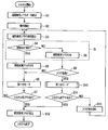
- FIG. 3 is a diagram illustrating a flowchart of an example of processing for handling an abnormal state that has occurred in the surgical operation system according to the embodiment of the present invention.
- FIG. 4 is a flowchart showing in detail the process in step S4 of the flowchart shown in FIG. 3 (a branch process from step S4 to step S5 or step S8; a process in the region D surrounded by a broken line in the flowchart). It is.
- FIG. 5 is a flowchart of a subroutine of the process of step S10 (setting process to the second mode) in the flowchart shown in FIG.
- FIG. 1 is a diagram illustrating a first configuration example of a surgery system according to the present embodiment.
- a master-slave type surgical system is assumed.
- a master-slave type surgical system is a system that has two types of arms, a master arm and a slave arm, and remotely controls the slave arm so as to follow the operation of the master arm.
- 1 includes an operating table 100, slave arms 200a to 200d, a slave control circuit 400, master arms 500a and 500b, an operation unit 600, an input processing circuit 700, an image processing circuit 800, Display 900a, 900b.
- the operating table 100 is a table on which a patient 1 to be observed and treated is placed. In the vicinity of the operating table 100, a plurality of slave arms 200a, 200b, 200c, and 200d are installed. The slave arms 200a to 200d may be installed on the operating table 100.
- Slave arms 200a, 200b, 200c, and 200d are each configured with a plurality of multi-degree-of-freedom joints. Such slave arms 200a, 200b, 200c, and 200d bend the respective joints so that the patient 1 placed on the operating table 100 faces the distal side of the slave arms 200a to 200d (towards the body cavity of the patient 1). Various surgical tools such as treatment tools and observation tools to be mounted on the side) are positioned.
- Each joint of the slave arms 200a to 200d is individually driven by a power unit provided in the arm.
- a power unit for example, a motor (servo motor) having a servo mechanism including an incremental encoder, a speed reducer, and the like is used.
- the operation control of the servo motor is performed by the slave control circuit 400.
- the slave arms 200a to 200d also have a plurality of power units for driving the surgical tools 240a to 240d attached to the respective distal ends.
- a servo motor is used as the power unit, and the operation control of the servo motor is also performed by the slave control circuit 400.
- the driving amount of the motor is detected by the position detector.
- a detection signal from the position detector is input to the slave control circuit 400, and the drive amount of the slave arms 200a to 200d is detected in the slave control circuit 400 by this detection signal.
- Surgical power transmission adapters (hereinafter simply referred to as adapters) 220a, 220b, 220c, and 220d are interposed between slave arms 200a, 200b, 200c, and 200d and surgical tools 240a, 240b, 240c, and 240d, and are slave arms.
- 200a, 200b, 200c, and 200d are connected to the surgical tools 240a, 240b, 240c, and 240d, respectively.
- each of the adapters 220a to 220d has a linear motion mechanism, and is configured to transmit the power generated in the power section of the corresponding slave arm to the corresponding surgical instrument by the linear motion. .
- the surgical tools 240a to 240d have joint portions having a plurality of degrees of freedom, and are inserted into the body cavity of the patient 1 through an insertion hole (not shown) opened in the body wall of the patient 1.
- the surgical tools 240a to 240d are configured such that the distal end portion can be driven to bend or rotate.
- This bending drive is performed, for example, by driving a servo motor provided in each of the slave arms 200a to 200d to push and pull the wires inserted and disposed in the surgical tools 240a to 240d.
- the rotation drive is performed, for example, by driving a servo motor provided in each of the slave arms 200a to 200d to operate a rotation mechanism provided in each of the surgical tools 240a to 240d.
- an opening / closing mechanism is provided at the distal end of the surgical instrument.
- This opening / closing mechanism is a mechanism for enabling an operation of grasping an instrument such as a needle or a thread for performing treatment, a blood vessel, an organ, and fat.
- This opening / closing mechanism is also operated by, for example, driving a servo motor provided in each of the slave arms 200a to 200d to push and pull a wire inserted and placed in the surgical instrument.
- the slave arms 200a, 200b, and 200d are used as slave arms for treatment.
- These surgical slave arms 200a, 200b, 200d are equipped with various surgical instruments as surgical tools 240a, 240b, 240d.
- the surgical instrument in this embodiment refers to a surgical instrument for performing a treatment on a tissue site in the patient 1 such as a scalpel or a scissors.
- the slave arm 200c is used as a camera arm for observation.
- Various observation instruments are attached to the slave arm 200c as the surgical instrument 240c.
- the observation instrument in the present embodiment refers to a surgical instrument for observing a tissue site in the body of the patient 1, such as an electronic endoscope.
- the surgical tools 240a to 240d attached to the adapters 220a to 220d can be replaced with replacement surgical tools 240e.
- Such a replacement operation of the surgical instrument is performed by the assistant 2, for example.
- the drape 300 is used to separate a site where the sterilization process is performed (hereinafter referred to as a clean area) and a site where the sterilization process is not performed (hereinafter referred to as an unclean area) in the surgical system according to the present embodiment.
- the sterilized surgical tools 240a to 240d are exposed to expose the slave arm 200a.
- the operation is performed in a state where the power parts of the slave arms 200a to 200d are wrapped by the drape 300 so that the power parts ⁇ 200d are protected.
- the slave control circuit 400 includes, for example, a CPU and a memory.
- the slave control circuit 400 stores a predetermined program for controlling the slave arms 200a to 200b, and operates the slave arms 200a to 200b or the surgical tools 240a to 240d in accordance with a control signal from the input processing circuit 700. To control.
- the slave control circuit 400 specifies the slave arm (or surgical tool) that is the operation target of the master arm operated by the operator 3 based on the control signal from the input processing circuit 700, and specifies the specified slave arm (operation technique).
- the driving amount necessary for causing the tool 3 to move corresponding to the operation amount of the master arm of the operator 3 is calculated.
- the slave control circuit 400 controls the operation of the slave arm to be operated by the master arm according to the calculated drive amount.
- the slave control circuit 400 inputs a drive signal to the corresponding slave arm, and determines the operation target according to the detection signal input from the position detector of the power unit according to the operation of the corresponding slave arm.
- the magnitude and polarity of the drive signal are controlled so that the drive amount of the slave arm becomes the target drive amount.
- the slave control circuit 400 also outputs the input image signal to the image processing circuit 800 when an image signal is input from an observation instrument attached to the slave arm 200c.
- the image processing circuit 800 detects (determines) the visual field abnormality.
- the image processing circuit 800 switches the control mode (first mode, second mode) based on the detection (determination) result of the visual field abnormality.
- the slave control circuit 400 controls the operation of each slave arm based on the control signal from the image processing circuit 800 so as to execute processing in each control mode.
- an ME 4 that is an engineer who confirms the state of the surgical system according to the present embodiment as shown in FIG.
- control mode first mode, second mode
- First mode is a control mode in a normal state (when no abnormality occurs in the imaging system).
- second mode is a control mode in a case where an image acquired by the imaging system is not normally displayed (abnormal state).
- the second mode is a control mode in which the contents of an abnormal state that has occurred (described below, “abnormality detection pattern”) and the processing that is executed at the time of abnormality (described below, “anomaly handling process”) are associated with each other. .
- the association setting of the second mode is appropriately performed according to, for example, the contents of the abnormal state and / or the operator of the surgical system. This setting may be defined in advance or may be changed as appropriate by the operator.
- abnormality detection pattern is, for example, the content of abnormality corresponding to each abnormality flag described later.
- Abnormality detection pattern 1 Monitor abnormality No image appears on the display 900a, 900b (no signal is sent to the monitor)
- Abnormality detection pattern 2 Color abnormality The color of the displayed image is inappropriate (the balance of RGB is extremely broken)
- Abnormality detection pattern 3 Cloudy abnormality
- the lens of the slave arm 200c, which is the camera arm for observation, is cloudy, the brightness is reduced, and the image has no edges.
- ⁇ Abnormality detection pattern 4 Noise abnormality Power supply system Noise is mixed in the image signal (when the image signal is subjected to frequency analysis, a large peak appears at a specific frequency)
- ⁇ Abnormality detection pattern 5 Abnormal frame Missing frame (Image processing cannot catch up with display update processing, timeout is detected)
- ⁇ Abnormality detection pattern 6 3D one-eye abnormality One-eye display in 3D display (the images of two endoscopes (left and right endoscopes) for obtaining a 3D display image are extremely different) It should be noted that each of the above-described ⁇ abnormality detection patterns >> is merely an example, and of course is not limited to the above-described example.
- “Abnormality detection pattern 1” and “Abnormality detection pattern 6” are abnormal states caused by abnormality in the imaging system, and “Abnormality detection pattern 2” to “Abnormality detection pattern 5” are display images. Is an abnormal state.
- the contents of the process (abnormality handling process) executed at the time of abnormality are, for example, the following processes.
- ⁇ Abnormality Handling Process 4 Process for retracting the arm of the imaging system to secure a wide field of view and then retracting and stopping the arm of the surgical instrument Slave arm 200c (for example, internal arm) equipped with various observation instruments as the surgical instrument 240c The endoscope etc.) is retracted to secure a wide field of view by the endoscope, and at least one of the slave arms 200a, 200b, 200d to which the surgical tools (surgical instruments) 240a, 240b, 240d are attached is The patient 1 is withdrawn from the body and stopped.
- Slave arm 200c for example, internal arm equipped with various observation instruments as the surgical instrument 240c
- the endoscope etc. is retracted to secure a wide field of view by the endoscope, and at least one of the slave arms 200a, 200b, 200d to which the surgical tools (surgical instruments) 240a, 240b, 240d are attached is The patient 1 is withdrawn from the body and stopped.
- Abnormality response processing 5 Processing that presents to the operator, assistant, ME, etc. that there is a possibility that an abnormality has occurred in the image (alarm, warning)
- the operator 3 and / or the assistant 2 are notified by audio / video, for example, that there is a possibility that an image reproduced and displayed on the displays 900a, 900b is abnormal.
- Abnormality Handling Process 6 When there is a possibility that an abnormality has occurred in the image, a process for presenting the abnormality content (display abnormality, color shift, cloudiness, one eye, etc.) to the operator, assistant, ME, etc. Display 900a , 900b, the operator 3 and / or the assistant 2 are informed of the content of the abnormality by, for example, audio / video or the like.
- the above-described “abnormality detection pattern” and “abnormality response processing” are set in association with each other, and a combination of “abnormality detection pattern” and “abnormality response processing” is set. May be defined in advance, or may be arbitrarily set by the user.
- the following settings may be performed.
- Weighting is performed for each abnormality detection pattern, and when the sum of the weights corresponding to the abnormality that has occurred reaches a predetermined value, the ⁇ abnormality handling process >> is changed.
- this setting may be a predetermined setting or may be arbitrarily set by the user.
- the setting may be appropriately changed according to the surgical experience, technical level, surgical target site, etc. of the operator of the surgical system.
- the master arms 500a and 500b are constituted by a plurality of link mechanisms.
- Each link constituting the link mechanism is provided with a position detector such as an incremental encoder. By detecting the operation of each link by this position detector, the operation amount of the master arms 500a and 500b is detected in the input processing circuit 700.
- FIG. 1 shows an example in which four slave arms are operated using two master arms 500a and 500b. In this case, it becomes necessary to appropriately switch the slave arm to be operated by the master arm. Such switching is performed, for example, by an operation of the operation unit 600 of the operator 3. Of course, if the number of master arms and the number of slave arms are the same, the operation target is made to correspond one-to-one, such switching is unnecessary.
- the operation unit 600 includes various operation members such as a switch button for switching the slave arm to be operated by the master arms 500a and 500b (hereinafter referred to as a switch button) and a foot switch for emergency stop of the system. Have.
- a switch button for switching the slave arm to be operated by the master arms 500a and 500b
- a foot switch for emergency stop of the system.
- the input processing circuit 700 analyzes the operation signals from the master arms 500a and 500b and the operation signal from the operation unit 600, generates a control signal for controlling the surgical system according to the analysis result of the operation signal, and generates a slave control circuit. Enter 400.
- the image processing circuit 800 controls the entire surgical system in an integrated manner in cooperation with the slave control circuit 400 and the input processing circuit 700.
- the processes in the flowcharts shown in FIGS. 3 to 5 described later are also performed mainly under the control of the image processing circuit 800.
- the image processing circuit 800 performs various image processing for displaying the image signal input from the slave control circuit 400, and generates image data for display on the operator display 900a and the assistant display 900b.
- the operator display 900a and the assistant display 900b are configured by, for example, a liquid crystal display, and display an image based on the image data generated in the image processing circuit 800 in accordance with an image signal acquired through the observation instrument.
- sterilized surgical tools 240a to 240d are mounted.
- various methods such as autoclave sterilization and EOG sterilization can be used.
- the operator 3 operates the master arms 500a and 500b while viewing the image displayed on the operator display 900a based on the image signal captured via the observation instrument attached to the tip of the slave arm 200c.
- detection signals from the position detectors attached to the links of the master arms 500 a and 500 b are input to the input processing circuit 700.
- an operation signal from the operation unit 600 is input to the input processing circuit 700.
- the input processing circuit 700 counts the number of times an operation signal is input from the switching button of the operation unit 600, and switches the slave arm to be operated by the master arms 500a and 500b according to the number of times the operation signal is input.
- the operation target of the master arm 500a is the slave arm 200a
- the operation target of the master arm 500b is the slave arm 200b.
- the input processing circuit 700 switches the operation target of the master arm 500a to the slave arm 200c or switches the operation target of the master arm 500b to the slave arm 200d.
- the input processing circuit 700 switches the operation target of the master arm 500a between the slave arm 200a and the slave arm 200c, or sets the operation target of the master arm 500b to the slave arm 200b. Switch between the slave arm 200d.
- the input processing circuit 700 determines the operation amount of the master arm from the value of the detection signal when the detection signal is input from any of the position detectors of the master arms 500a and 500b. Then, the input processing circuit 700 generates a control signal including information indicating the operation amount of the master arm operated by the operator 3 and information for determining the slave arm to be operated by the operated master arm. The generated control signal is input to the slave control circuit 400.
- the slave control circuit 400 calculates a driving amount necessary for causing the slave manipulator to move according to the operation of the master arm by the operator 3 in accordance with the control signal from the input processing circuit 700. Then, the slave control circuit 400 controls the magnitude and polarity of the drive signal input to the operation target slave arm so that the drive amount of the operation target slave arm of the master arm reaches the calculated drive amount.
- the slave control circuit 400 stops the slave arms 200a to 200d when the operator 3 is stepped on the foot switch and receives a control signal for emergency stop of the system from the input processing circuit 700.
- FIG. 2 is a diagram illustrating a second configuration example of the surgery system according to the present embodiment.
- a handy type surgical system is assumed.
- the handy-type surgical system refers to a system in which the operator 3 directly operates an arm on which a surgical instrument is mounted.
- the slave control circuit 400 shown in FIG. 2 is provided to control the operation of the arm 200c as a camera arm in a master-slave manner. If the arm 200c is also a handy type arm, the slave control circuit 400 is unnecessary.
- the handy arm 200f is installed in the vicinity of the operating table 100 like the slave arms 200a to 200d. Similarly to the slave arms 200a to 200d, the handy arm 200f also has a plurality of power units for driving a surgical instrument connected to the distal end side.
- the power unit of the handy arm 200f generates power in accordance with a drive signal from an operation unit (not shown) provided on the handy arm 200f.
- an adapter 220f similar to that shown in FIG. 1 is connected to the distal end of the handy arm 200f, and a surgical instrument 240f is connected to the distal end of the adapter 220f.
- the handy arm 200f, the adapter 220f, and the surgical instrument 240f are interchangeable with other handy arms 200g, the adapter 220g, and the surgical instrument 240g, respectively.
- Such a replacement operation of the surgical instrument is performed by the assistant 2, for example.
- FIG. 3 is a diagram illustrating an example of a flowchart in a case where the image acquired by the imaging system is not normally displayed (abnormal state) in the surgical system according to the present embodiment.
- the image processing circuit 800 reads various predetermined parameters and flags (step S1) and starts operation (step S2).
- the image processing circuit 800 presents the state of the “visual field abnormality flag” among the flags read in step S1 to the user (step S3). This presentation is performed using the displays 900a and 900b, for example.
- the “field abnormality flag” is a flag mainly related to the occurrence of an abnormal state in the imaging system, which will be described in detail later.
- An “abnormal flag”, “frame abnormal flag”, and “3D one-eye abnormal flag” are provided.
- the image processing circuit 800 receives the image data displayed on the displays 900a and 900b from the displays 900a and 900b, and determines whether or not the field of view is normal based on the image data (obtained by the imaging system). Whether or not the displayed image is normally displayed) is determined (step S4).
- FIG. 4 is a flowchart showing in detail the process in step S4 of the flowchart shown in FIG. 3 (a branch process from step S4 to step S5 or step S8; a process in the region D surrounded by a broken line in the flowchart). It is.
- a plurality of flags constituting the “field abnormality flag” (“monitor abnormality flag”, “color abnormality flag”, “cloudy abnormality flag”, “noise abnormality flag”, “frame abnormality”)
- the “flag” and “3D one-eye abnormality flag”) are determined in series.
- the image processing circuit 800 determines whether or not the video signal has reached the target monitors (displays 900a and 900b) (step S4-1).
- the “monitor abnormality flag” is set to ON (step S8-1).
- step S4-1 When step S4-1 is branched to YES or after the processing in step S8-1, the image processing circuit 800 has the color balance of the image reproduced and displayed on the target monitor (displays 900a and 900b) within the normal range. (Step S4-2).
- step S4-2 When step S4-2 is branched to NO (when the color balance of the image being reproduced and displayed is not within the normal range), the “color abnormality flag” is set to ON (step S8-2).
- step S4-2 When step S4-2 is branched to YES or after the processing in step S8-2, the image processing circuit 800 determines whether or not the image reproduced and displayed on the target monitor (displays 900a and 900b) is cloudy. (Step S4-3).
- step S4-3 When step S4-3 is branched to NO (when the video being reproduced and displayed is cloudy), the “cloudy abnormality flag” is set to ON (step S8-3).
- step S4-3 When step S4-3 is branched to YES or after the processing in step S8-3, the image processing circuit 800 causes the noise of the image reproduced and displayed on the target monitor (displays 900a and 900b) to be within the normal range. It is determined whether or not it is noise (step S4-4). When step S4-4 is branched to NO (when the noise of the image being reproduced and displayed is not within the normal range), the “noise abnormality flag” is set to ON (step S8-4).
- step S4-4 When step S4-4 is branched to YES or after the processing in step S8-4, the image processing circuit 800 determines whether there is no frame drop in the video reproduced and displayed on the target monitor (displays 900a and 900b). Is determined (step S4-5). When step S4-5 is branched to NO (when there is a frame drop in the video being reproduced and displayed), the “frame abnormality flag” is set to ON (step S8-5).
- step S4-5 When step S4-5 is branched to YES or after the processing in step S8-5, the image processing circuit 800 displays that the video reproduced and displayed on the target monitor (displays 900a and 900b) becomes “3D one-eye abnormality”. It is determined whether it is not (normal 3D display) (step S4-6). When this step S4-6 is branched to NO (when the video being reproduced is “3D one-eye abnormality (not normal 3D display)”), the “3D one-eye abnormality flag” is set to ON ( Step S8-6).
- step S4-6 is branched to NO means that, for example, only one of the two endoscopes for acquiring a 3D image has a normal stereoscopic image due to lens contamination or the like. This is a case where it cannot be acquired.
- steps S4-6 and S8-6 are unnecessary steps when the imaging system of the surgical system is not configured to perform 3D display.
- the determination in each step (steps S4-1 to S4-6) shown in the flowchart of FIG. 4 described above may be a determination at the moment of the determination, or a certain abnormal state continues for a certain period (a certain ratio). In such a case, it may be determined that there is an abnormality.
- the processing for determining each visual field abnormality flag in series is performed.
- the processing may be performed in parallel.
- step S9 step S4 is branched to YES.
- step S4 When step S4 is branched to YES (when the visual field is normal), the image processing circuit 800 sets all “visual field abnormality flags” to OFF and sets the surgical system to “first mode” ( Step S6).
- the “first mode” is a processing mode in a normal state (when no abnormality occurs in the imaging system).
- the image processing circuit 800 uses the displays 900a and 900b to perform a display requesting the user to determine whether or not to end the surgical system, and based on the user's response operation to the display, It is determined whether or not to end the system (step S7).
- step S7 When the user performs an operation to end the surgical system, the process branches off to YES in step S7, and the image processing circuit 800 writes the visual field abnormality flag set at the time in the nonvolatile memory or the like (step S12). ) And terminate the surgical system.
- step S7 is branched to NO, the process proceeds to step S3.
- step S9 if at least one of the steps S4-1 to S4-6 branches to NO and at least one “visual field abnormality flag” is set to ON (steps S8-1 to S8-). 6) Go to step S9.
- step S9 the image processing circuit 800 determines whether or not the visual field abnormality flag is “valid” at the time (step S9).
- This step S9 is a step in consideration of the case where the visual field abnormality flag has already been “invalidated” in step S13, which will be described later, and is still invalid at that time.
- step S9 When step S9 is branched to NO (when the visual field abnormality flag is invalid), the process proceeds to step S6. On the other hand, when step S9 is branched to YES (when the visual field abnormality flag is valid), the operation system is set to the “second mode” (step S10).
- FIG. 5 is a flowchart of a subroutine of the process of step S10 (setting process to the second mode) in the flowchart shown in FIG. That is, first, the image processing circuit 800 reads a preset “second mode setting” (step S10-1).
- the image processing circuit 800 sets the visual field abnormality flag (detected ⁇ abnormality detection pattern >>) set to ON at that time based on the setting of the second mode read in step S10-1.
- the associated ⁇ abnormality handling process >> is executed (step S10-2). Thereafter, the process proceeds to step S11 of the flowchart shown in FIG.
- the image processing circuit 800 uses the displays 900a and 900b to perform a display requesting the user to determine whether or not to end the surgical system, and based on the user's response operation to the display, It is determined whether or not to end the system (step S11).
- step S11 If the user performs an operation to end the surgical system, the process branches off to YES in step S11, and the image processing circuit 800 writes the visual field abnormality flag set at the time in the nonvolatile memory or the like (step S12). ) And terminate the surgical system.
- step S11 when processing in the surgical system is continued, the ON state of the “visual field abnormality flag” that is set to ON at that time is invalidated (step S13). ).
- a toggle switch may be used to switch between valid / invalid, or a timer function is used for a certain period of time ⁇ view error flag
- the ON state of >> may be invalidated.
- a surgical operation system including an imaging system is appropriately used when an image acquired by the imaging system is not normally displayed (abnormal state).
- a surgical system can be provided that performs the processing to be addressed.
- the visual field abnormality flag is set to ON / OFF and then the first mode and the second mode are switched. However, the mode is switched immediately when an abnormality is detected. Of course you can go.
- the above-described embodiments include inventions at various stages, and various inventions can be extracted by appropriately combining a plurality of disclosed constituent elements. For example, even if some configuration requirements are deleted from all the configuration requirements shown in the embodiment, the above-described problem can be solved, and this configuration requirement is deleted when the above-described effects can be obtained.
- the configuration can also be extracted as an invention.
Landscapes
- Health & Medical Sciences (AREA)
- Engineering & Computer Science (AREA)
- Life Sciences & Earth Sciences (AREA)
- Surgery (AREA)
- Robotics (AREA)
- General Health & Medical Sciences (AREA)
- Medical Informatics (AREA)
- Veterinary Medicine (AREA)
- Public Health (AREA)
- Nuclear Medicine, Radiotherapy & Molecular Imaging (AREA)
- Biomedical Technology (AREA)
- Heart & Thoracic Surgery (AREA)
- Animal Behavior & Ethology (AREA)
- Molecular Biology (AREA)
- Pathology (AREA)
- Physics & Mathematics (AREA)
- Optics & Photonics (AREA)
- Radiology & Medical Imaging (AREA)
- Biophysics (AREA)
- Endoscopes (AREA)
Abstract
The present invention pertains to a surgical system that determines whether an abnormal condition has occurred on the basis of image information acquired by an imaging system, and switches to an abnormality control mode in which processes for coping with abnormalities are performed, if it is determined that an abnormal condition has occurred.
Description
本発明は、例えば医療用マニピュレータシステム等の手術システムに関する。
The present invention relates to a surgical system such as a medical manipulator system.
近年、ロボットを用いた医療処置に係る技術について種々の提案が為されている。特に外科分野においては、多自由度アームを有する多自由度マニピュレータによって患者の処置をする医療用マニピュレータシステムについて各種の提案がなされている。
In recent years, various proposals have been made regarding techniques related to medical treatment using robots. Particularly in the field of surgery, various proposals have been made on medical manipulator systems for treating a patient with a multi-degree-of-freedom manipulator having multi-degree-of-freedom arms.
例えば特許文献1には、複数の医療用マニピュレータを使用した手術においてマニピュレータに何等かの動作不良が生じた場合に、それに対して速やかに対処できる安全性及び操作性に優れた医療用マニピュレータシステムが開示されている。
For example, Patent Document 1 discloses a medical manipulator system excellent in safety and operability that can quickly cope with a malfunction in a manipulator in an operation using a plurality of medical manipulators. It is disclosed.
具体的には、特許文献1に開示されている医療用マニピュレータシステムでは、赤外線センサーが所定量の赤外線を検知した場合に、センサー処理回路がそれを認識し、処置用スレーブマニピュレータの動作が停止される。
Specifically, in the medical manipulator system disclosed in Patent Document 1, when the infrared sensor detects a predetermined amount of infrared, the sensor processing circuit recognizes it and the operation of the treatment slave manipulator is stopped. The
例えば、赤外線センサーからの検知データ値が予め設定された閾値以上であるとセンサー処理回路で判断された場合には、センサー処理回路から処置用スレーブマニピュレータを実際に制御しているサーボ処理回路に停止命令が送られ、処置用スレーブマニピュレータの動作が停止される。このようにして、処置具の先端が、意図せずして臓器に接触してしまうことを防ぐことができる。
For example, if the sensor processing circuit determines that the detected data value from the infrared sensor is greater than or equal to a preset threshold, the sensor processing circuit stops at the servo processing circuit that actually controls the treatment slave manipulator A command is sent and the operation of the treatment slave manipulator is stopped. In this way, it is possible to prevent the distal end of the treatment tool from unintentionally coming into contact with the organ.
ところで、医療用マニピュレータシステムのうち撮像系(例えば内視鏡等)に異常が発生した場合には、術者は、視野を失う等の非常に大きな不都合を蒙る。従って、従来より医療用マニピュレータシステムのような手術システムにおいて、撮像系に生じた異常状態に対して適切且つ迅速に対処する技術が望まれている。なお、特許文献1に開示されている技術は、撮像系に生じた異常状態に対処する処理を規定しているものではない。
By the way, when an abnormality occurs in an imaging system (for example, an endoscope or the like) in the medical manipulator system, the surgeon suffers from a great inconvenience such as losing the visual field. Therefore, there has been a demand for a technique that appropriately and quickly copes with an abnormal state occurring in an imaging system in a surgical system such as a medical manipulator system. Note that the technique disclosed in Patent Document 1 does not prescribe a process for dealing with an abnormal state occurring in the imaging system.
本発明は、上記の事情に鑑みてなされたもので、撮像系を具備する手術システムであって、撮像系により取得した画像が正常に表示されていない状態(異常状態)である場合に、適切に対処する処理を実行する手術システムを提供することを目的とする。
The present invention has been made in view of the above circumstances, and is a surgical system including an imaging system, and is appropriate when an image acquired by the imaging system is not normally displayed (abnormal state). It is an object of the present invention to provide a surgical system that executes processing for dealing with the above.
上記の目的を達成するために、本発明の一態様の手術システムは、
画像情報を取得する撮像系を具備する手術システムであって、
前記画像情報に基づいて、当該手術システムに異常状態が生じているか否かを判定する判定部と、
前記判定部により異常状態が生じていると判定された場合に、異常対応処理を実行する異常時制御モードに切り替える制御部と、
を具備する。 In order to achieve the above object, a surgical system according to one aspect of the present invention includes:
A surgical system including an imaging system for acquiring image information,
A determination unit that determines whether an abnormal state has occurred in the surgical system based on the image information;
When it is determined by the determination unit that an abnormal state has occurred, a control unit that switches to an abnormal time control mode for executing an abnormality handling process;
It comprises.
本発明によれば、撮像系を具備する手術システムであって、撮像系により取得した画像が正常に表示されていない状態(異常状態)である場合に、適切に対処する処理を実行する手術システムを提供することができる。
According to the present invention, a surgical system that includes an imaging system, and performs a process that appropriately copes with a situation in which an image acquired by the imaging system is not normally displayed (abnormal state) Can be provided.
以下、図面を参照して本発明の一実施形態について説明する。
図1は、本一実施形態に係る手術システムの第1の構成例を示す図である。本例では、マスタースレーブ方式の手術システムを想定している。ここで、マスタースレーブ方式の手術システムとは、マスターアームとスレーブアームとからなる2種のアームを有し、マスターアームの動作に追従させるようにしてスレーブアームを遠隔制御するシステムのことを言うものとする。 Hereinafter, an embodiment of the present invention will be described with reference to the drawings.
FIG. 1 is a diagram illustrating a first configuration example of a surgery system according to the present embodiment. In this example, a master-slave type surgical system is assumed. Here, a master-slave type surgical system is a system that has two types of arms, a master arm and a slave arm, and remotely controls the slave arm so as to follow the operation of the master arm. And
図1に示す手術システムは、手術台100と、スレーブアーム200a~200dと、スレーブ制御回路400と、マスターアーム500a,500bと、操作部600と、入力処理回路700と、画像処理回路800と、ディスプレイ900a,900bと、を有している。
1 includes an operating table 100, slave arms 200a to 200d, a slave control circuit 400, master arms 500a and 500b, an operation unit 600, an input processing circuit 700, an image processing circuit 800, Display 900a, 900b.
手術台100は、観察・処置の対象となる患者1が載置される台である。この手術台100の近傍には、複数のスレーブアーム200a、200b、200c、200dが設置されている。なお、スレーブアーム200a~200dを手術台100に設置するようにしても良い。
The operating table 100 is a table on which a patient 1 to be observed and treated is placed. In the vicinity of the operating table 100, a plurality of slave arms 200a, 200b, 200c, and 200d are installed. The slave arms 200a to 200d may be installed on the operating table 100.
スレーブアーム200a、200b、200c、200dは、それぞれ複数の多自由度関節を有して構成されている。このようなスレーブアーム200a、200b、200c、200dは、各関節を湾曲させることによって、手術台100に載置された患者1に対してスレーブアーム200a~200dの先端側(患者1の体腔に向かう側とする)に装着される処置具や観察器具といった各種の術具を位置決めする。
Slave arms 200a, 200b, 200c, and 200d are each configured with a plurality of multi-degree-of-freedom joints. Such slave arms 200a, 200b, 200c, and 200d bend the respective joints so that the patient 1 placed on the operating table 100 faces the distal side of the slave arms 200a to 200d (towards the body cavity of the patient 1). Various surgical tools such as treatment tools and observation tools to be mounted on the side) are positioned.
スレーブアーム200a~200dの各関節は、アーム内に設けられた動力部によって個別に駆動される。この動力部としては、例えばインクリメンタルエンコーダや減速器等を備えたサーボ機構を有するモータ(サーボモータ)が用いられる。このサーボモータの動作制御は、スレーブ制御回路400によって行われる。
Each joint of the slave arms 200a to 200d is individually driven by a power unit provided in the arm. As the power unit, for example, a motor (servo motor) having a servo mechanism including an incremental encoder, a speed reducer, and the like is used. The operation control of the servo motor is performed by the slave control circuit 400.
さらに、スレーブアーム200a~200dは、各々の先端側に装着される術具240a~240dを駆動するための複数の動力部も有している。この動力部も例えばサーボモータが用いられ、このサーボモータの動作制御もスレーブ制御回路400によって行われる。
Furthermore, the slave arms 200a to 200d also have a plurality of power units for driving the surgical tools 240a to 240d attached to the respective distal ends. For example, a servo motor is used as the power unit, and the operation control of the servo motor is also performed by the slave control circuit 400.
スレーブアーム200a~200dの動力部が駆動された場合には、モータの駆動量が位置検出器によって検出される。位置検出器からの検出信号はスレーブ制御回路400に入力され、この検出信号により、スレーブアーム200a~200dの駆動量がスレーブ制御回路400において検出される。
When the power units of the slave arms 200a to 200d are driven, the driving amount of the motor is detected by the position detector. A detection signal from the position detector is input to the slave control circuit 400, and the drive amount of the slave arms 200a to 200d is detected in the slave control circuit 400 by this detection signal.
手術用動力伝達アダプタ(以下、単にアダプタと言う)220a、220b、220c、220dは、スレーブアーム200a、200b、200c、200dと術具240a、240b、240c、240dとの間に介在されてスレーブアーム200a、200b、200c、200dと術具240a、240b、240c、240dとをそれぞれ接続する。詳細は後述するが、アダプタ220a~220dは、それぞれが直動機構を有し、対応するスレーブアームの動力部において発生した動力を直動運動によって対応する術具に伝達するように構成されている。
Surgical power transmission adapters (hereinafter simply referred to as adapters) 220a, 220b, 220c, and 220d are interposed between slave arms 200a, 200b, 200c, and 200d and surgical tools 240a, 240b, 240c, and 240d, and are slave arms. 200a, 200b, 200c, and 200d are connected to the surgical tools 240a, 240b, 240c, and 240d, respectively. Although details will be described later, each of the adapters 220a to 220d has a linear motion mechanism, and is configured to transmit the power generated in the power section of the corresponding slave arm to the corresponding surgical instrument by the linear motion. .
術具240a~240dは、複数の自由度を有する関節部を有し、患者1の体壁に開けられた図示しない挿入孔から患者1の体腔内に挿入される。また、術具240a~240dは、先端部が湾曲駆動したり回転駆動したりできるように構成されている。
The surgical tools 240a to 240d have joint portions having a plurality of degrees of freedom, and are inserted into the body cavity of the patient 1 through an insertion hole (not shown) opened in the body wall of the patient 1. The surgical tools 240a to 240d are configured such that the distal end portion can be driven to bend or rotate.
この湾曲駆動は、例えばスレーブアーム200a~200d内にそれぞれ設けられたサーボモータを駆動させて術具240a~240d内に挿通配置されているワイヤを押し引き操作することによって行われる。また、回転駆動は、例えばスレーブアーム200a~200d内にそれぞれ設けられたサーボモータを駆動させて術具240a~240d内にそれぞれ設けられた回転機構を作動させたりすることによって行われる。
This bending drive is performed, for example, by driving a servo motor provided in each of the slave arms 200a to 200d to push and pull the wires inserted and disposed in the surgical tools 240a to 240d. The rotation drive is performed, for example, by driving a servo motor provided in each of the slave arms 200a to 200d to operate a rotation mechanism provided in each of the surgical tools 240a to 240d.
さらに、術具の種類によっては、術具の先端に開閉機構が設けられている。この開閉機構は、例えば、処置を行う為の針や糸等の器具、血管、臓器、及び脂肪等を把持する操作を可能とする為の機構である。この開閉機構も、例えばスレーブアーム200a~200dにそれぞれ設けられたサーボモータを駆動させて術具内に挿通配置されたワイヤを押し引き操作することにより作動される。
Furthermore, depending on the type of surgical instrument, an opening / closing mechanism is provided at the distal end of the surgical instrument. This opening / closing mechanism is a mechanism for enabling an operation of grasping an instrument such as a needle or a thread for performing treatment, a blood vessel, an organ, and fat. This opening / closing mechanism is also operated by, for example, driving a servo motor provided in each of the slave arms 200a to 200d to push and pull a wire inserted and placed in the surgical instrument.
ここで、図1に示す4本のスレーブアーム200a~200dのうち、例えば、スレーブアーム200a、200b、200dは処置用のスレーブアームとして用いられるものである。これら処置用のスレーブアーム200a、200b、200dには、術具240a、240b、240dとして各種の外科手術器具が装着される。
Here, among the four slave arms 200a to 200d shown in FIG. 1, for example, the slave arms 200a, 200b, and 200d are used as slave arms for treatment. These surgical slave arms 200a, 200b, 200d are equipped with various surgical instruments as surgical tools 240a, 240b, 240d.
なお、本一実施形態における外科手術器具とは、例えばメスや鋏等の、患者1の体内の組織部位に対して処置を行うための術具を言うものとする。また、スレーブアーム200cは観察用のカメラアームとして用いられるものである。スレーブアーム200cには、術具240cとして各種の観察器具が装着される。本一実施形態における観察器具とは、電子内視鏡等の、患者1の体内の組織部位を観察するための術具を言うものとする。
Note that the surgical instrument in this embodiment refers to a surgical instrument for performing a treatment on a tissue site in the patient 1 such as a scalpel or a scissors. The slave arm 200c is used as a camera arm for observation. Various observation instruments are attached to the slave arm 200c as the surgical instrument 240c. The observation instrument in the present embodiment refers to a surgical instrument for observing a tissue site in the body of the patient 1, such as an electronic endoscope.
また、アダプタ220a~220dに装着された術具240a~240dは、交換用術具240eと交換可能になされている。このような術具の交換作業は、例えば助手2によって行われる。
In addition, the surgical tools 240a to 240d attached to the adapters 220a to 220d can be replaced with replacement surgical tools 240e. Such a replacement operation of the surgical instrument is performed by the assistant 2, for example.
ドレープ300は、本一実施形態に係る手術システムにおいて滅菌処理を行う部位(以下、清潔域と称する)と滅菌処理を行わない部位(以下、不潔域と称する)とを分けるためものである。
The drape 300 is used to separate a site where the sterilization process is performed (hereinafter referred to as a clean area) and a site where the sterilization process is not performed (hereinafter referred to as an unclean area) in the surgical system according to the present embodiment.
例えば、メスや鋏等の外科手術器具は患者1の体腔内に直接接触するものであり、洗浄処理や滅菌処理を十分に行っておく必要がある。これに対し、スレーブアーム200a~200dの動力部等は各種の電子部品を備えているため、通常は滅菌処理に耐え得る構造をしていない。
For example, surgical instruments such as scalpels and scissors are in direct contact with the body cavity of the patient 1 and need to be sufficiently cleaned and sterilized. On the other hand, since the power parts and the like of the slave arms 200a to 200d are provided with various electronic components, they are not normally structured to withstand sterilization.
したがって、アダプタ220a~220dを介してスレーブアーム200a~200dに術具240a~240dを装着した状態で手術を行う際には、滅菌処理済みの術具240a~240dの部分を露出させ、スレーブアーム200a~200dの動力部が保護されるように、図1に示すように、スレーブアーム200a~200dの動力部の部分をドレープ300によって包むようにした状態で手術を行う。
Therefore, when performing an operation with the surgical tools 240a to 240d attached to the slave arms 200a to 200d via the adapters 220a to 220d, the sterilized surgical tools 240a to 240d are exposed to expose the slave arm 200a. As shown in FIG. 1, the operation is performed in a state where the power parts of the slave arms 200a to 200d are wrapped by the drape 300 so that the power parts ~ 200d are protected.
ドレープ300によって清潔域と不潔域とを分けておくことにより、手術中において清潔域と不潔域との交錯を防止する。
清潔 By separating the clean area and the unclean area with the drape 300, it is possible to prevent the clean area and the unclean area from intermingling during the operation.
スレーブ制御回路400は、例えばCPUやメモリ等を有して構成されている。このスレーブ制御回路400は、スレーブアーム200a~200bの制御を行うための所定のプログラムを記憶しており、入力処理回路700からの制御信号に従って、スレーブアーム200a~200b又は術具240a~240dの動作を制御する。
The slave control circuit 400 includes, for example, a CPU and a memory. The slave control circuit 400 stores a predetermined program for controlling the slave arms 200a to 200b, and operates the slave arms 200a to 200b or the surgical tools 240a to 240d in accordance with a control signal from the input processing circuit 700. To control.
即ち、スレーブ制御回路400は、入力処理回路700からの制御信号に基づいて、操作者3によって操作されたマスターアームの操作対象のスレーブアーム(又は術具)を特定し、特定したスレーブアーム(術具)に操作者3のマスターアームの操作量に対応した動きをさせるために必要な駆動量を演算する。そして、スレーブ制御回路400は、算出した駆動量に応じてマスターアームの操作対象のスレーブアームの動作を制御する。この際、スレーブ制御回路400は、対応したスレーブアームに駆動信号を入力するとともに、対応したスレーブアームの動作に応じて動力部の位置検出器から入力されてくる検出信号に応じて、操作対象のスレーブアームの駆動量が目標の駆動量となるように駆動信号の大きさや極性を制御する。
That is, the slave control circuit 400 specifies the slave arm (or surgical tool) that is the operation target of the master arm operated by the operator 3 based on the control signal from the input processing circuit 700, and specifies the specified slave arm (operation technique). The driving amount necessary for causing the tool 3 to move corresponding to the operation amount of the master arm of the operator 3 is calculated. Then, the slave control circuit 400 controls the operation of the slave arm to be operated by the master arm according to the calculated drive amount. At this time, the slave control circuit 400 inputs a drive signal to the corresponding slave arm, and determines the operation target according to the detection signal input from the position detector of the power unit according to the operation of the corresponding slave arm. The magnitude and polarity of the drive signal are controlled so that the drive amount of the slave arm becomes the target drive amount.
さらに、スレーブ制御回路400は、スレーブアーム200cに装着された観察器具から画像信号が入力されてきた場合には、入力された画像信号を画像処理回路800に出力することも行う。なお、詳細は後述するが、この画像信号に基づいて、画像処理回路800は、視野異常の検出(判定)を行う。そして、画像処理回路800は、この視野異常の検出(判定)結果に基づいて、制御モード(第一のモード、第二のモード)を切り替える。この際、スレーブ制御回路400は、画像処理回路800からの制御信号に基づいて、各々の制御モードにおける処理を実行するように、各スレーブアームの動作制御を行う。
Furthermore, the slave control circuit 400 also outputs the input image signal to the image processing circuit 800 when an image signal is input from an observation instrument attached to the slave arm 200c. Although details will be described later, based on the image signal, the image processing circuit 800 detects (determines) the visual field abnormality. Then, the image processing circuit 800 switches the control mode (first mode, second mode) based on the detection (determination) result of the visual field abnormality. At this time, the slave control circuit 400 controls the operation of each slave arm based on the control signal from the image processing circuit 800 so as to execute processing in each control mode.
また、スレーブ制御回路400近傍には、図1に示すように本一実施形態に係る手術システムの状態等を確認するエンジニアであるME4が位置している場合もある。
Also, in the vicinity of the slave control circuit 400, there may be an ME 4 that is an engineer who confirms the state of the surgical system according to the present embodiment as shown in FIG.
ここで、前記制御モード(第一のモード、第二のモード)について詳細に説明する。
Here, the control mode (first mode, second mode) will be described in detail.
“第一のモード”とは、通常時(撮像系に異常が生じていない場合)の制御モードである。一方、“第二のモード”とは、撮像系により取得した画像が正常に表示されていない状態(異常状態)である場合の制御モードである。この第二のモードは、発生した異常状態の内容(後述する“異常検出パターン”)と、異常時に実行する処理(後述する“異常対応処理”)内容と、が対応付けされた制御モードである。
“First mode” is a control mode in a normal state (when no abnormality occurs in the imaging system). On the other hand, the “second mode” is a control mode in a case where an image acquired by the imaging system is not normally displayed (abnormal state). The second mode is a control mode in which the contents of an abnormal state that has occurred (described below, “abnormality detection pattern”) and the processing that is executed at the time of abnormality (described below, “anomaly handling process”) are associated with each other. .
この第二のモードの対応付け設定は、例えば異常状態の内容、及び/または当該手術システムの操作者に応じて適宜為される。この設定は予め規定されていてもよいし、操作者により適宜変更可能にしてもよい。
The association setting of the second mode is appropriately performed according to, for example, the contents of the abnormal state and / or the operator of the surgical system. This setting may be defined in advance or may be changed as appropriate by the operator.
前記異常の内容(異常検出パターン)とは、例えば後述の各異常フラグに対応する異常の内容である。
The content of abnormality (abnormality detection pattern) is, for example, the content of abnormality corresponding to each abnormality flag described later.
《異常検出パターン1》モニタ異常
ディスプレイ900a,900bに全く画像が来ていない(モニタへ信号は来ていない)
《異常検出パターン2》色異常
表示画像の色が不適切(RGBのバランスが極端に崩れている)
《異常検出パターン3》くもり異常
観察用のカメラアームであるスレーブアーム200cのレンズが曇っている、明度が低下している、エッジの無い画像になっている
《異常検出パターン4》ノイズ異常
電源系のノイズが画像信号に混入している(画像信号を周波数解析すると特定周波数に大きなピークが立っている)
《異常検出パターン5》フレーム異常
フレームが欠落している(画像処理が表示更新処理に追いつかない、タイムアウトを検出している)
《異常検出パターン6》3D片目異常
3D表示において片目表示となっている(3D表示画像を取得する為の2台の内視鏡(左右の内視鏡)の画像が極端に違う)
なお、上述の各《異常検出パターン》はあくまでも一例であって、上述の例に限られないことは勿論である。 << Abnormality detection pattern 1 >> Monitor abnormality No image appears on the display 900a, 900b (no signal is sent to the monitor)
<<Abnormality detection pattern 2 >> Color abnormality The color of the displayed image is inappropriate (the balance of RGB is extremely broken)
<<Abnormality detection pattern 3 >> Cloudy abnormality The lens of the slave arm 200c, which is the camera arm for observation, is cloudy, the brightness is reduced, and the image has no edges. << Abnormality detection pattern 4 >> Noise abnormality Power supply system Noise is mixed in the image signal (when the image signal is subjected to frequency analysis, a large peak appears at a specific frequency)
<< Abnormality detection pattern 5 >> Abnormal frame Missing frame (Image processing cannot catch up with display update processing, timeout is detected)
<< Abnormality detection pattern 6 >> 3D one-eye abnormality One-eye display in 3D display (the images of two endoscopes (left and right endoscopes) for obtaining a 3D display image are extremely different)
It should be noted that each of the above-described << abnormality detection patterns >> is merely an example, and of course is not limited to the above-described example.
ディスプレイ900a,900bに全く画像が来ていない(モニタへ信号は来ていない)
《異常検出パターン2》色異常
表示画像の色が不適切(RGBのバランスが極端に崩れている)
《異常検出パターン3》くもり異常
観察用のカメラアームであるスレーブアーム200cのレンズが曇っている、明度が低下している、エッジの無い画像になっている
《異常検出パターン4》ノイズ異常
電源系のノイズが画像信号に混入している(画像信号を周波数解析すると特定周波数に大きなピークが立っている)
《異常検出パターン5》フレーム異常
フレームが欠落している(画像処理が表示更新処理に追いつかない、タイムアウトを検出している)
《異常検出パターン6》3D片目異常
3D表示において片目表示となっている(3D表示画像を取得する為の2台の内視鏡(左右の内視鏡)の画像が極端に違う)
なお、上述の各《異常検出パターン》はあくまでも一例であって、上述の例に限られないことは勿論である。 << Abnormality detection pattern 1 >> Monitor abnormality No image appears on the
<<
<<
<< Abnormality detection pattern 5 >> Abnormal frame Missing frame (Image processing cannot catch up with display update processing, timeout is detected)
<< Abnormality detection pattern 6 >> 3D one-eye abnormality One-eye display in 3D display (the images of two endoscopes (left and right endoscopes) for obtaining a 3D display image are extremely different)
It should be noted that each of the above-described << abnormality detection patterns >> is merely an example, and of course is not limited to the above-described example.
上述の異常検出パターンのうち、《異常検出パターン1》及び《異常検出パターン6》は撮像系の異常に起因する異常状態であり、《異常検出パターン2》~《異常検出パターン5》は表示画像に係る異常状態である。
Among the above-described abnormality detection patterns, “Abnormality detection pattern 1” and “Abnormality detection pattern 6” are abnormal states caused by abnormality in the imaging system, and “Abnormality detection pattern 2” to “Abnormality detection pattern 5” are display images. Is an abnormal state.
ところで、前記異常時に実行する処理(異常対応処理)内容とは、例えば次のような処理である。
By the way, the contents of the process (abnormality handling process) executed at the time of abnormality are, for example, the following processes.
《異常対応処理1》その場で停止処理
スレーブアーム200a~200dのうち少なくとも1つを、その場で停止させる。 << Abnormality handling process 1 >> Stop process on the spot At least one of theslave arms 200a to 200d is stopped on the spot.
スレーブアーム200a~200dのうち少なくとも1つを、その場で停止させる。 << Abnormality handling process 1 >> Stop process on the spot At least one of the
《異常対応処理2》退避させて停止処理
スレーブアーム200a~200dのうち少なくとも1つを、患者1の体外に後退させてから停止させる。 <<Abnormality Handling Process 2 >> Retreating and Stopping Process At least one of the slave arms 200a to 200d is retracted outside the body of the patient 1 and then stopped.
スレーブアーム200a~200dのうち少なくとも1つを、患者1の体外に後退させてから停止させる。 <<
《異常対応処理3》術具による把持を解除してから退避させて停止処理
スレーブアーム200a、200b、200dの術具(外科手術器具)240a、240b、240dのうち少なくとも1つの把持状態を解除してから、スレーブアーム200a、200b、200dのうち少なくとも1つを、患者1の体外に後退させてから停止させる。 <<Abnormality handling process 3 >> After the grasping by the surgical tool is released, the holding process is performed and the stop process is performed. Then, at least one of the slave arms 200a, 200b, and 200d is retracted outside the body of the patient 1 and then stopped.
スレーブアーム200a、200b、200dの術具(外科手術器具)240a、240b、240dのうち少なくとも1つの把持状態を解除してから、スレーブアーム200a、200b、200dのうち少なくとも1つを、患者1の体外に後退させてから停止させる。 <<
《異常対応処理4》撮像系のアームを後退させて広い視野を確保した上で術具のアームを退避させて停止させる処理
術具240cとして各種の観察器具が装着されたスレーブアーム200c(例えば内視鏡等)を後退させて、内視鏡による広い視野を確保した上で、術具(外科手術器具)240a、240b、240dが装着されたスレーブアーム200a、200b、200dのうち少なくとも1つを、患者1の体外に退避させて停止させる。 << Abnormality Handling Process 4 >> Process for retracting the arm of the imaging system to secure a wide field of view and then retracting and stopping the arm of the surgicalinstrument Slave arm 200c (for example, internal arm) equipped with various observation instruments as the surgical instrument 240c The endoscope etc.) is retracted to secure a wide field of view by the endoscope, and at least one of the slave arms 200a, 200b, 200d to which the surgical tools (surgical instruments) 240a, 240b, 240d are attached is The patient 1 is withdrawn from the body and stopped.
術具240cとして各種の観察器具が装着されたスレーブアーム200c(例えば内視鏡等)を後退させて、内視鏡による広い視野を確保した上で、術具(外科手術器具)240a、240b、240dが装着されたスレーブアーム200a、200b、200dのうち少なくとも1つを、患者1の体外に退避させて停止させる。 << Abnormality Handling Process 4 >> Process for retracting the arm of the imaging system to secure a wide field of view and then retracting and stopping the arm of the surgical
《異常対応処理5》画像に異常が生じている可能性があることを操作者、助手、及びME等に提示する処理(アラーム、ワーニング)
ディスプレイ900a,900bに再生表示されている画像に異常が生じている可能性があることを、例えば音声・映像等によって、操作者3及び/または助手2に対して報知する。 << Abnormality response processing 5 >> Processing that presents to the operator, assistant, ME, etc. that there is a possibility that an abnormality has occurred in the image (alarm, warning)
Theoperator 3 and / or the assistant 2 are notified by audio / video, for example, that there is a possibility that an image reproduced and displayed on the displays 900a, 900b is abnormal.
ディスプレイ900a,900bに再生表示されている画像に異常が生じている可能性があることを、例えば音声・映像等によって、操作者3及び/または助手2に対して報知する。 << Abnormality response processing 5 >> Processing that presents to the operator, assistant, ME, etc. that there is a possibility that an abnormality has occurred in the image (alarm, warning)
The
《異常対応処理6》画像に異常が生じている可能性がある場合に、その異常内容(表示異常、色ずれ、くもり、片目など)を操作者、助手、及びME等に提示する処理
ディスプレイ900a,900bに再生表示されている画像に異常が生じている可能性がある場合に、その異常内容を、例えば音声・映像等によって、操作者3及び/または助手2に対して報知する。 << Abnormality Handling Process 6 >> When there is a possibility that an abnormality has occurred in the image, a process for presenting the abnormality content (display abnormality, color shift, cloudiness, one eye, etc.) to the operator, assistant, ME, etc. Display 900a , 900b, the operator 3 and / or the assistant 2 are informed of the content of the abnormality by, for example, audio / video or the like.
ディスプレイ900a,900bに再生表示されている画像に異常が生じている可能性がある場合に、その異常内容を、例えば音声・映像等によって、操作者3及び/または助手2に対して報知する。 << Abnormality Handling Process 6 >> When there is a possibility that an abnormality has occurred in the image, a process for presenting the abnormality content (display abnormality, color shift, cloudiness, one eye, etc.) to the operator, assistant, ME, etc.
《異常対応処理7》特別な処理を何も行わない
撮像系において異常が発生したからといって、必ずしも特別な処理が必要となるわけではない。従って、特別な処理が必要でない場合には、特別な処理を何も行わない(実質的に、通常時(撮像系に異常が生じていない場合)の処理モードである“第一のモード”に設定されている状態と同じ)。 << Abnormality Handling Processing 7 >> No special processing is performed. Even if an abnormality occurs in the imaging system, special processing is not necessarily required. Therefore, when no special processing is required, no special processing is performed (substantially, the “first mode” which is a processing mode in a normal state (when no abnormality occurs in the imaging system). Same as set).
撮像系において異常が発生したからといって、必ずしも特別な処理が必要となるわけではない。従って、特別な処理が必要でない場合には、特別な処理を何も行わない(実質的に、通常時(撮像系に異常が生じていない場合)の処理モードである“第一のモード”に設定されている状態と同じ)。 << Abnormality Handling Processing 7 >> No special processing is performed. Even if an abnormality occurs in the imaging system, special processing is not necessarily required. Therefore, when no special processing is required, no special processing is performed (substantially, the “first mode” which is a processing mode in a normal state (when no abnormality occurs in the imaging system). Same as set).
なお、上述の各《異常対応処理》はあくまでも一例であって、上述の例に限られないことは勿論である。
It should be noted that each of the above-described << abnormality handling processes >> is merely an example, and of course is not limited to the above-described example.
ここで、“第二のモード”においては、上述の《異常検出パターン》と《異常対応処理》とが対応付けられて設定されており、《異常検出パターン》と《異常対応処理》との組み合わせは予め規定されてもよいし、ユーザが任意に設定できるようにしてもよい。
Here, in the “second mode”, the above-described “abnormality detection pattern” and “abnormality response processing” are set in association with each other, and a combination of “abnormality detection pattern” and “abnormality response processing” is set. May be defined in advance, or may be arbitrarily set by the user.
さらに、“第二のモード”においては、例えば次のような設定を行ってもよい。
Furthermore, in the “second mode”, for example, the following settings may be performed.
[視野異常フラグに優先順位をつける設定]
同時に複数の視野異常フラグがONに設定された場合の為に、各異常フラグ間で優先順位をつける。そして、同時に複数の視野異常フラグがONに設定された場合には、優先順位がより上位の視野異常フラグに対応する異常対応処理を実行する。 [Setting to give priority to visual field abnormality flag]
Since a plurality of visual field abnormality flags are set to ON at the same time, priorities are set between the respective abnormality flags. When a plurality of visual field abnormality flags are set to ON at the same time, an abnormality handling process corresponding to a visual field abnormality flag with a higher priority is executed.
[異常フラグがONされた回数に基づいて、異常対応処理を変更していく設定]
例えば、或る視野異常フラグが一度目のON時には《異常対応処理5》を実行し、二度目のON時には《異常対応処理6》を実行する処理を行う。 [Setting to change the abnormality handling process based on the number of times the abnormality flag is turned on]
For example, when a certain visual field abnormality flag is turned on for the first time, “abnormality handling processing 5” is executed, and when the certain visual field abnormality flag is turned on for the second time, “abnormality handling processing 6” is executed.
[異常検出パターン毎に重み付けを行う設定]
異常検出パターン毎に重み付けを行い、発生した異常に対応する重みの和が所定値に達すると、《異常対応処理》を変更する。 [Setting for weighting each abnormality detection pattern]
Weighting is performed for each abnormality detection pattern, and when the sum of the weights corresponding to the abnormality that has occurred reaches a predetermined value, the << abnormality handling process >> is changed.
以上、“第二のモード”の設定について説明したが、この設定は、予め定めた設定としてもよいし、ユーザが任意に設定できるようにしてもよい。また、当該手術システムの操作者の手術経験、技術レベル、手術対象部位等によって、適宜、設定変更可能に構成してもよい。
As described above, the setting of the “second mode” has been described. However, this setting may be a predetermined setting or may be arbitrarily set by the user. In addition, the setting may be appropriately changed according to the surgical experience, technical level, surgical target site, etc. of the operator of the surgical system.
ところで、マスターアーム500a、500bは複数のリンク機構で構成されている。リンク機構を構成する各リンクには例えばインクリメンタルエンコーダ等の位置検出器が設けられている。この位置検出器によって各リンクの動作を検知することで、マスターアーム500a、500bの操作量が入力処理回路700において検出される。
Incidentally, the master arms 500a and 500b are constituted by a plurality of link mechanisms. Each link constituting the link mechanism is provided with a position detector such as an incremental encoder. By detecting the operation of each link by this position detector, the operation amount of the master arms 500a and 500b is detected in the input processing circuit 700.
なお、図1の例において、マスターアーム500aが操作者3の右手によって操作されるアームであり、マスターアーム500bが操作者3の左手によって操作されるアームである。このように、図1は、2本のマスターアーム500a、500bを用いて4本のスレーブアームを操作する場合の例を示している。この場合、マスターアームの操作対象のスレーブアームを適宜切り替える必要が生じる。このような切り替えは、例えば操作者3の操作部600の操作によって行われる。勿論、マスターアームの本数とスレーブアームの本数とを同数とすることで操作対象を1対1の対応とすれば、このような切り替えは不要である。
In the example of FIG. 1, the master arm 500a is an arm operated by the right hand of the operator 3, and the master arm 500b is an arm operated by the left hand of the operator 3. Thus, FIG. 1 shows an example in which four slave arms are operated using two master arms 500a and 500b. In this case, it becomes necessary to appropriately switch the slave arm to be operated by the master arm. Such switching is performed, for example, by an operation of the operation unit 600 of the operator 3. Of course, if the number of master arms and the number of slave arms are the same, the operation target is made to correspond one-to-one, such switching is unnecessary.
操作部600は、マスターアーム500a、500bの操作対象のスレーブアームを切り替えるための切替ボタン(以下、切替ボタンと言う)や、システムを緊急停止させたりするためのフットスイッチ等の各種の操作部材を有している。操作者3によって操作部600を構成する何れかの操作部材が操作された場合には、対応する操作部材の操作に応じた操作信号が操作部600から入力処理回路700に入力される。
The operation unit 600 includes various operation members such as a switch button for switching the slave arm to be operated by the master arms 500a and 500b (hereinafter referred to as a switch button) and a foot switch for emergency stop of the system. Have. When any of the operation members constituting the operation unit 600 is operated by the operator 3, an operation signal corresponding to the operation of the corresponding operation member is input from the operation unit 600 to the input processing circuit 700.
入力処理回路700は、マスターアーム500a、500bからの操作信号及び操作部600からの操作信号を解析し、操作信号の解析結果に従って本手術システムを制御するための制御信号を生成してスレーブ制御回路400に入力する。
The input processing circuit 700 analyzes the operation signals from the master arms 500a and 500b and the operation signal from the operation unit 600, generates a control signal for controlling the surgical system according to the analysis result of the operation signal, and generates a slave control circuit. Enter 400.
画像処理回路800は、スレーブ制御回路400及び入力処理回路700と協働して当該手術システム全体を統括的に制御する。後述する図3乃至図5に示すフローチャートにおける処理も、主として画像処理回路800による制御で行われる。
The image processing circuit 800 controls the entire surgical system in an integrated manner in cooperation with the slave control circuit 400 and the input processing circuit 700. The processes in the flowcharts shown in FIGS. 3 to 5 described later are also performed mainly under the control of the image processing circuit 800.
また、画像処理回路800は、スレーブ制御回路400から入力された画像信号を表示させるための各種の画像処理を施して、操作者用ディスプレイ900a、助手用ディスプレイ900bにおける表示用の画像データを生成する。操作者用ディスプレイ900a及び助手用ディスプレイ900bは、例えば液晶ディスプレイで構成され、観察器具を介して取得された画像信号に従って画像処理回路800において生成された画像データに基づく画像を表示する。
The image processing circuit 800 performs various image processing for displaying the image signal input from the slave control circuit 400, and generates image data for display on the operator display 900a and the assistant display 900b. . The operator display 900a and the assistant display 900b are configured by, for example, a liquid crystal display, and display an image based on the image data generated in the image processing circuit 800 in accordance with an image signal acquired through the observation instrument.
上述した図1の構成の手術システムにおいては、まず滅菌処理済みの術具240a~240dを装着する。本実施形態における滅菌処理としてはオートクレーブ滅菌やEOG滅菌等の各種の方式を用いることができる。
In the surgical system having the configuration shown in FIG. 1 described above, first, sterilized surgical tools 240a to 240d are mounted. As the sterilization treatment in the present embodiment, various methods such as autoclave sterilization and EOG sterilization can be used.
操作者3は、スレーブアーム200cの先端に装着された観察器具を介して取り込まれた画像信号に基づいて操作者用ディスプレイ900aに表示された画像を見ながら、マスターアーム500a、500bを操作する。操作者3によるマスターアーム500a、500bの操作を受けて、マスターアーム500a、500bの各リンクに取り付けられた位置検出器からの検出信号が入力処理回路700に入力される。また、操作部600の切替ボタンが操作されることにより、操作部600からの操作信号が入力処理回路700に入力される。
The operator 3 operates the master arms 500a and 500b while viewing the image displayed on the operator display 900a based on the image signal captured via the observation instrument attached to the tip of the slave arm 200c. In response to the operation of the master arms 500 a and 500 b by the operator 3, detection signals from the position detectors attached to the links of the master arms 500 a and 500 b are input to the input processing circuit 700. Further, when the switching button of the operation unit 600 is operated, an operation signal from the operation unit 600 is input to the input processing circuit 700.
入力処理回路700は、操作部600の切替ボタンからの操作信号の入力回数をカウントしており、この操作信号の入力回数に従って、マスターアーム500a、500bの操作対象のスレーブアームの切り替えを行う。例えば、初期状態では、マスターアーム500aの操作対象をスレーブアーム200aとし、マスターアーム500bの操作対象をスレーブアーム200bとしておく。
The input processing circuit 700 counts the number of times an operation signal is input from the switching button of the operation unit 600, and switches the slave arm to be operated by the master arms 500a and 500b according to the number of times the operation signal is input. For example, in the initial state, the operation target of the master arm 500a is the slave arm 200a, and the operation target of the master arm 500b is the slave arm 200b.
この初期状態において、切替ボタンが1回押された場合に、入力処理回路700は、マスターアーム500aの操作対象をスレーブアーム200cに切り替えたり、マスターアーム500bの操作対象をスレーブアーム200dに切り替える。以下、切替ボタンが1回押される毎に、入力処理回路700は、マスターアーム500aの操作対象をスレーブアーム200aとスレーブアーム200cとの間で切り替えたり、マスターアーム500bの操作対象をスレーブアーム200bとスレーブアーム200dとの間で切り替える。
In this initial state, when the switching button is pressed once, the input processing circuit 700 switches the operation target of the master arm 500a to the slave arm 200c or switches the operation target of the master arm 500b to the slave arm 200d. Hereinafter, every time the switching button is pressed, the input processing circuit 700 switches the operation target of the master arm 500a between the slave arm 200a and the slave arm 200c, or sets the operation target of the master arm 500b to the slave arm 200b. Switch between the slave arm 200d.
さらに、入力処理回路700は、マスターアーム500a、500bの何れかの位置検出器から検出信号が入力された場合に、検出信号の値からマスターアームの操作量を判別する。そして、入力処理回路700は、操作者3によって操作されたマスターアームの操作量を示す情報と、操作されたマスターアームの操作対象のスレーブアームを判別するための情報とを含む制御信号を生成し、生成した制御信号をスレーブ制御回路400に入力する。
Further, the input processing circuit 700 determines the operation amount of the master arm from the value of the detection signal when the detection signal is input from any of the position detectors of the master arms 500a and 500b. Then, the input processing circuit 700 generates a control signal including information indicating the operation amount of the master arm operated by the operator 3 and information for determining the slave arm to be operated by the operated master arm. The generated control signal is input to the slave control circuit 400.
スレーブ制御回路400は、入力処理回路700からの制御信号に従って、操作者3によるマスターアームの操作に応じた動きをスレーブマニピュレータにさせるために必要な駆動量を演算する。そして、スレーブ制御回路400は、マスターアームの操作対象のスレーブアームの駆動量が演算した駆動量に達するように、操作対象のスレーブアームに入力する駆動信号の大きさや極性を制御する。
The slave control circuit 400 calculates a driving amount necessary for causing the slave manipulator to move according to the operation of the master arm by the operator 3 in accordance with the control signal from the input processing circuit 700. Then, the slave control circuit 400 controls the magnitude and polarity of the drive signal input to the operation target slave arm so that the drive amount of the operation target slave arm of the master arm reaches the calculated drive amount.
また、スレーブ制御回路400は、操作者3によってフットスイッチ踏まれて入力処理回路700からシステムの緊急停止をさせる旨の制御信号が入力されたときには、スレーブアーム200a~200dを停止させる。
The slave control circuit 400 stops the slave arms 200a to 200d when the operator 3 is stepped on the foot switch and receives a control signal for emergency stop of the system from the input processing circuit 700.
図2は、本一実施形態に係る手術システムの第2の構成例を示す図である。図2に示す例では、ハンディタイプの手術システムを想定している。ここで、ハンディタイプの手術システムとは、外科手術器具が装着されたアームを操作者3が直接操作するシステムのことを言うものとする。
FIG. 2 is a diagram illustrating a second configuration example of the surgery system according to the present embodiment. In the example shown in FIG. 2, a handy type surgical system is assumed. Here, the handy-type surgical system refers to a system in which the operator 3 directly operates an arm on which a surgical instrument is mounted.
図2において、図1と同一又は対応する構成については図1と同一の参照符号を付すことで説明を省略する。
2, the same or corresponding components as those in FIG. 1 are denoted by the same reference numerals as those in FIG. 1 and description thereof is omitted.
ここで、図2に示すスレーブ制御回路400は、カメラアームとしてのアーム200cの動作をマスタースレーブ方式で制御するために設けられている。アーム200cについてもハンディタイプのアームとするのであれば、スレーブ制御回路400は不要である。
Here, the slave control circuit 400 shown in FIG. 2 is provided to control the operation of the arm 200c as a camera arm in a master-slave manner. If the arm 200c is also a handy type arm, the slave control circuit 400 is unnecessary.
ハンディアーム200fは、スレーブアーム200a~200dと同様、手術台100の近傍に設置されている。ハンディアーム200fも、スレーブアーム200a~200dと同様、先端側に接続される術具を駆動するための複数の動力部を有している。
The handy arm 200f is installed in the vicinity of the operating table 100 like the slave arms 200a to 200d. Similarly to the slave arms 200a to 200d, the handy arm 200f also has a plurality of power units for driving a surgical instrument connected to the distal end side.
ハンディアーム200fの動力部は、ハンディアーム200fに設けられている図示しない操作部からの駆動信号に従って動力を発生する。また、図2に示すように、ハンディアーム200fの先端にも図1で示したのと同様のアダプタ220fが接続され、さらに、アダプタ220fの先端には術具240fが接続される。
The power unit of the handy arm 200f generates power in accordance with a drive signal from an operation unit (not shown) provided on the handy arm 200f. As shown in FIG. 2, an adapter 220f similar to that shown in FIG. 1 is connected to the distal end of the handy arm 200f, and a surgical instrument 240f is connected to the distal end of the adapter 220f.
ハンディアーム200f、アダプタ220f、術具240fは、それぞれ、別のハンディアーム200g、アダプタ220g、術具240gと交換可能になされている。このような術具の交換作業は、例えば助手2によって行われる。
The handy arm 200f, the adapter 220f, and the surgical instrument 240f are interchangeable with other handy arms 200g, the adapter 220g, and the surgical instrument 240g, respectively. Such a replacement operation of the surgical instrument is performed by the assistant 2, for example.
図2で示した構成の手術システムにおいては、操作者3がハンディアーム200fの図示しない操作部を操作することにより、ハンディアーム200fや術具240fが駆動される。その他の動作については図1で説明した動作が適用される。
2, when the operator 3 operates an operation unit (not shown) of the handy arm 200f, the handy arm 200f and the surgical instrument 240f are driven. The operation described with reference to FIG. 1 is applied to other operations.
図3は、本一実施形態に係る手術システムにおいて、撮像系により取得した画像が正常に表示されていない状態(異常状態)である場合の一例のフローチャートを示す図である。
FIG. 3 is a diagram illustrating an example of a flowchart in a case where the image acquired by the imaging system is not normally displayed (abnormal state) in the surgical system according to the present embodiment.
まず、当該手術システムが起動処理されると、画像処理回路800は所定の各種パラメータやフラグを読み込み(ステップS1)、動作を開始する(ステップS2)。ここで、画像処理回路800は、ステップS1において読み込んだフラグのうち“視野異常フラグ”の状態を、ユーザに提示する(ステップS3)。この提示は、例えばディスプレイ900a,900bを利用して行われる。
First, when the operation system is activated, the image processing circuit 800 reads various predetermined parameters and flags (step S1) and starts operation (step S2). Here, the image processing circuit 800 presents the state of the “visual field abnormality flag” among the flags read in step S1 to the user (step S3). This presentation is performed using the displays 900a and 900b, for example.
“視野異常フラグ”は、詳細は後述するが主として撮像系における異常状態の発生に係るフラグであり、本例では、“モニタ異常フラグ”、“色異常フラグ”、“くもり異常フラグ”、“ノイズ異常フラグ”、“フレーム異常フラグ”、及び“3D片目異常フラグ”を設けている。
The “field abnormality flag” is a flag mainly related to the occurrence of an abnormal state in the imaging system, which will be described in detail later. In this example, the “monitor abnormality flag”, “color abnormality flag”, “cloudy abnormality flag”, “noise” An “abnormal flag”, “frame abnormal flag”, and “3D one-eye abnormal flag” are provided.
続いて、画像処理回路800は、ディスプレイ900a,900bに表示されている画像データを、ディスプレイ900a,900bから受信し、該画像データに基づいて、視野が正常であるか否か(撮像系により取得した画像が正常に表示されているか否か)を判定する(ステップS4)。
Subsequently, the image processing circuit 800 receives the image data displayed on the displays 900a and 900b from the displays 900a and 900b, and determines whether or not the field of view is normal based on the image data (obtained by the imaging system). Whether or not the displayed image is normally displayed) is determined (step S4).
このステップS4における処理(ステップS4からステップS5又はステップS8への分岐処理;同フローチャートにおいて破線で囲まれた領域D内の処理)は、詳細には次のような処理である。図4は、図3に示すフローチャートのステップS4における処理(ステップS4からステップS5又はステップS8への分岐処理;同フローチャートにおいて破線で囲まれた領域D内の処理)を詳細に記すフローチャートを示す図である。
The processing in step S4 (branching processing from step S4 to step S5 or step S8; processing in the region D surrounded by a broken line in the flowchart) is the following processing in detail. FIG. 4 is a flowchart showing in detail the process in step S4 of the flowchart shown in FIG. 3 (a branch process from step S4 to step S5 or step S8; a process in the region D surrounded by a broken line in the flowchart). It is.
図4に示すように、本例では、“視野異常フラグ”を構成する複数のフラグ(“モニタ異常フラグ”、“色異常フラグ”、“くもり異常フラグ”、“ノイズ異常フラグ”、“フレーム異常フラグ”、及び“3D片目異常フラグ”)について直列的に判定していく。
As shown in FIG. 4, in this example, a plurality of flags constituting the “field abnormality flag” (“monitor abnormality flag”, “color abnormality flag”, “cloudy abnormality flag”, “noise abnormality flag”, “frame abnormality”) The “flag” and “3D one-eye abnormality flag”) are determined in series.
すなわち、まず、画像処理回路800は、対象のモニタ(ディスプレイ900a,900b)に映像信号が届いているか否かを判定する(ステップS4-1)。このステップS4-1をNOに分岐する場合(対象のモニタに映像信号が届いていない場合)、“モニタ異常フラグ”をONに設定する(ステップS8-1)。
That is, first, the image processing circuit 800 determines whether or not the video signal has reached the target monitors ( displays 900a and 900b) (step S4-1). When this step S4-1 is branched to NO (when the video signal does not reach the target monitor), the “monitor abnormality flag” is set to ON (step S8-1).
ステップS4-1をYESに分岐する場合またはステップS8-1における処理の後、画像処理回路800は、対象のモニタ(ディスプレイ900a,900b)にて再生表示されている画像の色バランスが正常範囲内に収まっているかを判定する(ステップS4-2)。このステップS4-2をNOに分岐する場合(再生表示されている画像の色バランスが正常範囲内に収まっていない場合)、“色異常フラグ”をONに設定する(ステップS8-2)。
When step S4-1 is branched to YES or after the processing in step S8-1, the image processing circuit 800 has the color balance of the image reproduced and displayed on the target monitor ( displays 900a and 900b) within the normal range. (Step S4-2). When step S4-2 is branched to NO (when the color balance of the image being reproduced and displayed is not within the normal range), the “color abnormality flag” is set to ON (step S8-2).
ステップS4-2をYESに分岐する場合またはステップS8-2における処理の後、画像処理回路800は、対象のモニタ(ディスプレイ900a,900b)にて再生表示されている映像がくもっていないか否か判定する(ステップS4-3)。このステップS4-3をNOに分岐する場合(再生表示されている映像がくもっている場合)、“くもり異常フラグ”をONに設定する(ステップS8-3)。
When step S4-2 is branched to YES or after the processing in step S8-2, the image processing circuit 800 determines whether or not the image reproduced and displayed on the target monitor ( displays 900a and 900b) is cloudy. (Step S4-3). When step S4-3 is branched to NO (when the video being reproduced and displayed is cloudy), the “cloudy abnormality flag” is set to ON (step S8-3).
ステップS4-3をYESに分岐する場合またはステップS8-3における処理の後、画像処理回路800は、対象のモニタ(ディスプレイ900a,900b)にて再生表示されている画像のノイズが正常範囲内のノイズであるか否か判定する(ステップS4-4)。このステップS4-4をNOに分岐する場合(再生表示されている画像のノイズが正常範囲内のノイズでない場合)、“ノイズ異常フラグ”をONに設定する(ステップS8-4)。
When step S4-3 is branched to YES or after the processing in step S8-3, the image processing circuit 800 causes the noise of the image reproduced and displayed on the target monitor ( displays 900a and 900b) to be within the normal range. It is determined whether or not it is noise (step S4-4). When step S4-4 is branched to NO (when the noise of the image being reproduced and displayed is not within the normal range), the “noise abnormality flag” is set to ON (step S8-4).
ステップS4-4をYESに分岐する場合またはステップS8-4における処理の後、画像処理回路800は、対象のモニタ(ディスプレイ900a,900b)にて再生表示されている映像にフレーム落ちが無いか否かを判定する(ステップS4-5)。このステップS4-5をNOに分岐する場合(再生表示されている映像にフレーム落ちが有る場合)、“フレーム異常フラグ”をONに設定する(ステップS8-5)。
When step S4-4 is branched to YES or after the processing in step S8-4, the image processing circuit 800 determines whether there is no frame drop in the video reproduced and displayed on the target monitor ( displays 900a and 900b). Is determined (step S4-5). When step S4-5 is branched to NO (when there is a frame drop in the video being reproduced and displayed), the “frame abnormality flag” is set to ON (step S8-5).
ステップS4-5をYESに分岐する場合またはステップS8-5における処理の後、画像処理回路800は、対象のモニタ(ディスプレイ900a,900b)にて再生表示されている映像が“3D片目異常になっていないか(正常な3D表示であるか否か)”を判定する(ステップS4-6)。このステップS4-6をNOに分岐する場合(再生表示されている映像が“3D片目異常になっている(正常な3D表示でない)”場合)、“3D片目異常フラグ”をONに設定する(ステップS8-6)。
When step S4-5 is branched to YES or after the processing in step S8-5, the image processing circuit 800 displays that the video reproduced and displayed on the target monitor ( displays 900a and 900b) becomes “3D one-eye abnormality”. It is determined whether it is not (normal 3D display) (step S4-6). When this step S4-6 is branched to NO (when the video being reproduced is “3D one-eye abnormality (not normal 3D display)”), the “3D one-eye abnormality flag” is set to ON ( Step S8-6).
ここで、ステップS4-6をNOに分岐する場合とは、例えば、3D画像を取得する為の2台の内視鏡のうち片方の内視鏡のみが、レンズ汚れ等により正常な立体画像を取得できない状態となっている場合である。
Here, the case where step S4-6 is branched to NO means that, for example, only one of the two endoscopes for acquiring a 3D image has a normal stereoscopic image due to lens contamination or the like. This is a case where it cannot be acquired.
なお、ステップS4-6及びステップS8-6は、当該手術システムの撮像系が3D表示を行う仕様に構成されていない場合には不要なステップである。
Note that steps S4-6 and S8-6 are unnecessary steps when the imaging system of the surgical system is not configured to perform 3D display.
以上説明した図4のフローチャートに示す各ステップ(ステップS4-1~ステップS4-6)における判定は、当該判定時の瞬間においての判定でもよいし、或る異常状態が一定時間(一定割合)持続した場合に異常であると判定するとしてもよい。
The determination in each step (steps S4-1 to S4-6) shown in the flowchart of FIG. 4 described above may be a determination at the moment of the determination, or a certain abnormal state continues for a certain period (a certain ratio). In such a case, it may be determined that there is an abnormality.
なお、図4に示す処理例では、各視野異常フラグについて直列的に判断していく処理としているが、並列的に判断していく処理としても勿論よい。
In the processing example shown in FIG. 4, the processing for determining each visual field abnormality flag in series is performed. However, the processing may be performed in parallel.
上述した図4に示すフローチャートの処理を終えると、一つでも視野異常フラグがONに設定されている場合にはステップS9へ移行し、全ての視野異常フラグがONに設定されなかった場合にはステップS5へ移行する(当該ステップS4をYESに分岐する)。
When the process of the flowchart shown in FIG. 4 is finished, if at least one of the visual field abnormality flags is set to ON, the process proceeds to step S9. If all of the visual field abnormality flags are not set to ON, The process proceeds to step S5 (step S4 is branched to YES).
ステップS4をYESに分岐した場合(視野が正常である場合)、画像処理回路800は、全ての“視野異常フラグ”をOFFに設定し、当該手術システムを“第一のモード”に設定する(ステップS6)。ここで“第一のモード”とは、通常時(撮像系に異常が生じていない場合)の処理モードである。
When step S4 is branched to YES (when the visual field is normal), the image processing circuit 800 sets all “visual field abnormality flags” to OFF and sets the surgical system to “first mode” ( Step S6). Here, the “first mode” is a processing mode in a normal state (when no abnormality occurs in the imaging system).
その後、画像処理回路800は、“当該手術システムを終了するか否か”の判断をユーザに求める表示をディスプレイ900a,900bを利用して行い、該表示に対するユーザの応答操作に基づいて、当該手術システムを終了するか否かを判断する(ステップS7)。
Thereafter, the image processing circuit 800 uses the displays 900a and 900b to perform a display requesting the user to determine whether or not to end the surgical system, and based on the user's response operation to the display, It is determined whether or not to end the system (step S7).
ユーザにより当該手術システムの終了操作が行われた場合、ステップS7をYESに分岐し、画像処理回路800は、当該時点において設定されている状態の視野異常フラグを不揮発性メモリ等に書き込み(ステップS12)、当該手術システムを終了させる。一方、ステップS7をNOに分岐する場合は、前記ステップS3へ移行する。
When the user performs an operation to end the surgical system, the process branches off to YES in step S7, and the image processing circuit 800 writes the visual field abnormality flag set at the time in the nonvolatile memory or the like (step S12). ) And terminate the surgical system. On the other hand, when step S7 is branched to NO, the process proceeds to step S3.
ところで、前記ステップS4-1~ステップS4-6のうち少なくとも何れか一つのステップをNOに分岐し、少なくとも一つの“視野異常フラグ”がONに設定されると(ステップS8-1~ステップS8-6)、ステップS9に移行する。
By the way, if at least one of the steps S4-1 to S4-6 branches to NO and at least one “visual field abnormality flag” is set to ON (steps S8-1 to S8-). 6) Go to step S9.
このステップS9において、画像処理回路800は、当該時点において視野異常フラグが“有効”であるか否かを判定する(ステップS9)。このステップS9は、後述するステップS13において視野異常フラグが既に“無効化処理”されており、当該時点においても未だ無効のままである場合を考慮したステップである。
In step S9, the image processing circuit 800 determines whether or not the visual field abnormality flag is “valid” at the time (step S9). This step S9 is a step in consideration of the case where the visual field abnormality flag has already been “invalidated” in step S13, which will be described later, and is still invalid at that time.
このステップS9をNOに分岐する場合(視野異常フラグが無効である場合)、前記ステップS6に移行する。一方ステップS9をYESに分岐する場合(視野異常フラグが有効である場合)、当該手術システムを“第二のモード”に設定する(ステップS10)。
When step S9 is branched to NO (when the visual field abnormality flag is invalid), the process proceeds to step S6. On the other hand, when step S9 is branched to YES (when the visual field abnormality flag is valid), the operation system is set to the “second mode” (step S10).
このステップS10における処理は、詳細には次のような処理である。図5は、図3に示すフローチャートにおけるステップS10の処理(第二のモードへの設定処理)のサブルーチンのフローチャートを示す図である。すなわち、まず、画像処理回路800は、予め設定されている“第二のモードの設定”を読み込む(ステップS10-1)。
The processing in step S10 is the following processing in detail. FIG. 5 is a flowchart of a subroutine of the process of step S10 (setting process to the second mode) in the flowchart shown in FIG. That is, first, the image processing circuit 800 reads a preset “second mode setting” (step S10-1).
そして、画像処理回路800は、前記ステップS10-1において読み込んだ第二のモードの設定に基づいて、当該時点においてONに設定されている視野異常フラグ(検出されている《異常検出パターン》)に対応付けされている《異常対応処理》を実行する(ステップS10-2)。その後、図3に示すフローチャートのステップS11へ移行する。
Then, the image processing circuit 800 sets the visual field abnormality flag (detected << abnormality detection pattern >>) set to ON at that time based on the setting of the second mode read in step S10-1. The associated << abnormality handling process >> is executed (step S10-2). Thereafter, the process proceeds to step S11 of the flowchart shown in FIG.
そして、画像処理回路800は、“当該手術システムを終了するか否か”の判断をユーザに求める表示をディスプレイ900a,900bを利用して行い、該表示に対するユーザの応答操作に基づいて、当該手術システムを終了するか否かを判断する(ステップS11)。
Then, the image processing circuit 800 uses the displays 900a and 900b to perform a display requesting the user to determine whether or not to end the surgical system, and based on the user's response operation to the display, It is determined whether or not to end the system (step S11).
ユーザにより当該手術システムの終了操作が行われた場合、ステップS11をYESに分岐し、画像処理回路800は、当該時点において設定されている状態の視野異常フラグを不揮発性メモリ等に書き込み(ステップS12)、当該手術システムを終了させる。
If the user performs an operation to end the surgical system, the process branches off to YES in step S11, and the image processing circuit 800 writes the visual field abnormality flag set at the time in the nonvolatile memory or the like (step S12). ) And terminate the surgical system.
他方、ステップS11をNOに分岐する場合は(当該手術システムでの処理を続行する場合は)、当該時点においてONに設定されている《視野異常フラグ》のON状態を無効化処理する(ステップS13)。
On the other hand, when step S11 is branched to NO (when processing in the surgical system is continued), the ON state of the “visual field abnormality flag” that is set to ON at that time is invalidated (step S13). ).
具体的には、このステップS13における無効化処理の為に、例えばトグルスイッチを用いて有効/無効の切替えを行うように構成しても良いし、タイマ機能を用いて一定時間だけ《視野異常フラグ》のON状態を無効化するように構成してもよい。このステップS13における処理の後、前記ステップS3に移行する。
Specifically, for the invalidation process in this step S13, for example, a toggle switch may be used to switch between valid / invalid, or a timer function is used for a certain period of time << view error flag The ON state of >> may be invalidated. After the process in step S13, the process proceeds to step S3.
以上説明したように、本一実施形態によれば、撮像系を具備する手術システムであって、撮像系により取得した画像が正常に表示されていない状態(異常状態)である場合に、適切に対処する処理を実行する手術システムを提供することができる。
As described above, according to the present embodiment, a surgical operation system including an imaging system is appropriately used when an image acquired by the imaging system is not normally displayed (abnormal state). A surgical system can be provided that performs the processing to be addressed.
従来より、手術システムにおいて撮像系に異常が発生した場合には、操作者等が当該撮像系の異常を認知してから、手動でスレーブマニピュレータの動作を停止させる等の処理を行っている。従って、撮像系に異常が発生してから実際に当該異常に対処するまでに、或る程度の時間が掛かってしまう(タイムラグが生じる)。しかしながら、本一実施形態に係る手術システムによれば、撮像系における異常(例えば内視鏡の故障等)が生じた場合に、そのことについての操作者の認知とは関係なく、速やかに異常対応処理が実行される。これにより、利便性が非常に向上する。
Conventionally, when an abnormality occurs in an imaging system in a surgical system, processing such as manually stopping the operation of a slave manipulator is performed after an operator or the like has recognized the abnormality in the imaging system. Therefore, it takes a certain amount of time (a time lag occurs) from when an abnormality occurs in the imaging system to when the abnormality is actually dealt with. However, according to the surgery system according to the present embodiment, when an abnormality occurs in the imaging system (for example, an endoscope failure or the like), the abnormality is promptly dealt with regardless of the operator's perception of the abnormality. Processing is executed. This greatly improves convenience.
なお、上述の例では、視野異常フラグのON/OFF設定を行った上で、第1のモードと第二のモードとの切り替えを行っているが、異常が検出された時点で直ちにモード切り替えを行っても勿論よい。
In the above example, the visual field abnormality flag is set to ON / OFF and then the first mode and the second mode are switched. However, the mode is switched immediately when an abnormality is detected. Of course you can go.
以上、一実施形態に基づいて本発明を説明したが、本発明は上述した実施形態に限定されるものではなく、本発明の要旨の範囲内で種々の変形や応用が可能なことは勿論である。
As mentioned above, although this invention was demonstrated based on one Embodiment, this invention is not limited to embodiment mentioned above, Of course, a various deformation | transformation and application are possible within the range of the summary of this invention. is there.
さらに、上記した実施形態には種々の段階の発明が含まれており、開示される複数の構成要件の適当な組合せにより種々の発明が抽出され得る。例えば、実施形態に示される全構成要件からいくつかの構成要件が削除されても、上述したような課題を解決でき、上述したような効果が得られる場合には、この構成要件が削除された構成も発明として抽出され得る。
Furthermore, the above-described embodiments include inventions at various stages, and various inventions can be extracted by appropriately combining a plurality of disclosed constituent elements. For example, even if some configuration requirements are deleted from all the configuration requirements shown in the embodiment, the above-described problem can be solved, and this configuration requirement is deleted when the above-described effects can be obtained. The configuration can also be extracted as an invention.
Claims (4)
- 画像情報を取得する撮像系を具備する手術システムであって、
前記画像情報に基づいて、当該手術システムに異常状態が生じているか否かを判定する判定部と、
前記判定部により異常状態が生じていると判定された場合に、異常対応処理を実行する異常時制御モードに切り替える制御部と、
を具備することを特徴とする手術システム。 A surgical system including an imaging system for acquiring image information,
A determination unit that determines whether an abnormal state has occurred in the surgical system based on the image information;
When it is determined by the determination unit that an abnormal state has occurred, a control unit that switches to an abnormal time control mode for executing an abnormality handling process;
A surgical system comprising: - 当該手術システムには、前記画像情報を表示する表示部材が接続されており、
前記異常状態とは、前記撮像系の故障に起因する異常状態と、前記表示部材に表示された画像情報に係る異常状態と、のうち少なくとも何れか一方に該当する状態である
ことを特徴とする請求項1に記載の手術システム。 A display member for displaying the image information is connected to the surgical system,
The abnormal state is a state corresponding to at least one of an abnormal state caused by a failure of the imaging system and an abnormal state related to image information displayed on the display member. The surgical system according to claim 1. - 前記異常対応処理とは、当該手術システムで利用している手術器具を停止させる処理と、異常状態が生じている旨を、当該手術システムによる手術に係る者に提示する処理と、生じている異常状態の内容を当該手術システムによる手術に係る者に提示する処理と、何ら特別な処理を行わない為の処理と、のうち少なくとも何れか一つの処理である
ことを特徴とする請求項1に記載の手術システム。 The abnormality handling process includes a process of stopping a surgical instrument used in the surgical system, a process of presenting that an abnormal state has occurred to a person involved in the operation by the surgical system, and an abnormality that has occurred The process according to claim 1, wherein at least one of a process for presenting the contents of the state to a person involved in an operation by the operation system and a process for not performing any special process. Surgical system. - 前記制御部が前記異常時制御モードにおいて実行する異常対応処理の処理内容は、生じている異常状態の内容、及び/または当該手術システムの操作者に対応付けされて設定されている
ことを特徴とする請求項1乃至請求項3のうち何れか一つに記載の手術システム。 The processing content of the abnormality handling processing executed by the control unit in the abnormal time control mode is set in association with the content of the abnormal state that has occurred and / or the operator of the surgical system. The surgical operation system according to any one of claims 1 to 3.
Priority Applications (2)
| Application Number | Priority Date | Filing Date | Title |
|---|---|---|---|
| EP12757164.4A EP2687181B1 (en) | 2011-03-15 | 2012-03-12 | Surgical system |
| CN201280012794.2A CN103429188B (en) | 2011-03-15 | 2012-03-12 | Surgery systems |
Applications Claiming Priority (2)
| Application Number | Priority Date | Filing Date | Title |
|---|---|---|---|
| JP2011057050A JP5856745B2 (en) | 2011-03-15 | 2011-03-15 | Surgical system and control method thereof |
| JP2011-057050 | 2011-03-15 |
Publications (1)
| Publication Number | Publication Date |
|---|---|
| WO2012124651A1 true WO2012124651A1 (en) | 2012-09-20 |
Family
ID=46829060
Family Applications (1)
| Application Number | Title | Priority Date | Filing Date |
|---|---|---|---|
| PCT/JP2012/056261 WO2012124651A1 (en) | 2011-03-15 | 2012-03-12 | Surgical system |
Country Status (5)
| Country | Link |
|---|---|
| US (1) | US9585724B2 (en) |
| EP (1) | EP2687181B1 (en) |
| JP (1) | JP5856745B2 (en) |
| CN (1) | CN103429188B (en) |
| WO (1) | WO2012124651A1 (en) |
Families Citing this family (5)
| Publication number | Priority date | Publication date | Assignee | Title |
|---|---|---|---|---|
| JP5996492B2 (en) | 2013-07-25 | 2016-09-21 | オリンパス株式会社 | Joint mechanisms and medical devices |
| JP6485899B2 (en) * | 2014-12-08 | 2019-03-20 | ソニー・オリンパスメディカルソリューションズ株式会社 | Medical stereoscopic observation apparatus, medical stereoscopic observation method, and program |
| WO2016125398A1 (en) | 2015-02-03 | 2016-08-11 | オリンパス株式会社 | Medical manipulator system and control method therefor |
| US11284963B2 (en) * | 2019-12-30 | 2022-03-29 | Cilag Gmbh International | Method of using imaging devices in surgery |
| CN111568558B (en) * | 2020-04-13 | 2022-02-22 | 上海市胸科医院 | Electronic device, surgical robot system, and control method thereof |
Citations (4)
| Publication number | Priority date | Publication date | Assignee | Title |
|---|---|---|---|---|
| JP2005296198A (en) * | 2004-04-08 | 2005-10-27 | Olympus Corp | Medical system |
| JP3717552B2 (en) | 1995-09-01 | 2005-11-16 | オリンパス株式会社 | Medical manipulator system |
| JP2006025912A (en) * | 2004-07-13 | 2006-02-02 | Olympus Corp | Surgical microscope |
| JP2007007040A (en) * | 2005-06-29 | 2007-01-18 | Hitachi Medical Corp | Surgery support system |
Family Cites Families (14)
| Publication number | Priority date | Publication date | Assignee | Title |
|---|---|---|---|---|
| DE69634714T2 (en) * | 1995-03-31 | 2006-01-19 | Kabushiki Kaisha Toshiba, Kawasaki | Therapeutic ultrasound device |
| US6245028B1 (en) * | 1999-11-24 | 2001-06-12 | Marconi Medical Systems, Inc. | Needle biopsy system |
| JP2003334164A (en) * | 2002-05-21 | 2003-11-25 | Olympus Optical Co Ltd | Endoscope system |
| JP2008538184A (en) * | 2005-02-22 | 2008-10-16 | マコ サージカル コーポレーション | Tactile guidance system and method |
| DE102005036998B4 (en) * | 2005-08-05 | 2014-11-20 | Siemens Aktiengesellschaft | Device for the automatic detection of abnormalities in medical image data |
| DE102006008509A1 (en) * | 2006-02-23 | 2007-08-02 | Siemens Ag | Conspicuousness detecting method, involves testing image with detection algorithm automatically, where image data sets are registered, in order to obtain transformations |
| JP5242381B2 (en) * | 2006-03-16 | 2013-07-24 | オリンパスメディカルシステムズ株式会社 | Medical image processing apparatus and medical image processing method |
| JP2008194179A (en) | 2007-02-09 | 2008-08-28 | Olympus Medical Systems Corp | Rotary self-traveling endoscope system |
| JP4932559B2 (en) | 2007-03-26 | 2012-05-16 | オリンパスメディカルシステムズ株式会社 | Automatic insertion type electronic endoscope device, control program for automatic insertion type electronic endoscope device |
| JP2009225851A (en) * | 2008-03-19 | 2009-10-08 | Fujinon Corp | Processor device of endoscope |
| JP2010004979A (en) * | 2008-06-25 | 2010-01-14 | Fujifilm Corp | Image processor and processor for endoscope |
| JP5127636B2 (en) * | 2008-08-29 | 2013-01-23 | 富士フイルム株式会社 | Processor device for electronic endoscope |
| JPWO2011052391A1 (en) * | 2009-10-28 | 2013-03-21 | オリンパスメディカルシステムズ株式会社 | Medical device |
| JP6021353B2 (en) * | 2011-08-04 | 2016-11-09 | オリンパス株式会社 | Surgery support device |
-
2011
- 2011-03-15 JP JP2011057050A patent/JP5856745B2/en not_active Expired - Fee Related
-
2012
- 2012-03-12 CN CN201280012794.2A patent/CN103429188B/en active Active
- 2012-03-12 WO PCT/JP2012/056261 patent/WO2012124651A1/en unknown
- 2012-03-12 EP EP12757164.4A patent/EP2687181B1/en not_active Not-in-force
- 2012-03-13 US US13/418,683 patent/US9585724B2/en active Active
Patent Citations (4)
| Publication number | Priority date | Publication date | Assignee | Title |
|---|---|---|---|---|
| JP3717552B2 (en) | 1995-09-01 | 2005-11-16 | オリンパス株式会社 | Medical manipulator system |
| JP2005296198A (en) * | 2004-04-08 | 2005-10-27 | Olympus Corp | Medical system |
| JP2006025912A (en) * | 2004-07-13 | 2006-02-02 | Olympus Corp | Surgical microscope |
| JP2007007040A (en) * | 2005-06-29 | 2007-01-18 | Hitachi Medical Corp | Surgery support system |
Non-Patent Citations (1)
| Title |
|---|
| See also references of EP2687181A4 |
Also Published As
| Publication number | Publication date |
|---|---|
| US20120239058A1 (en) | 2012-09-20 |
| EP2687181A1 (en) | 2014-01-22 |
| CN103429188B (en) | 2016-08-10 |
| EP2687181B1 (en) | 2019-03-06 |
| US9585724B2 (en) | 2017-03-07 |
| EP2687181A4 (en) | 2014-10-08 |
| JP2012192004A (en) | 2012-10-11 |
| JP5856745B2 (en) | 2016-02-10 |
| CN103429188A (en) | 2013-12-04 |
Similar Documents
| Publication | Publication Date | Title |
|---|---|---|
| EP2550926B1 (en) | Medical manipulator system | |
| US8583274B2 (en) | Method for graphically providing continuous change of state directions to a user of medical robotic system | |
| EP3616594B1 (en) | Endoscope adaptor and method of attaching endoscope to robot arm through the same | |
| CN107249497B (en) | Operating room and surgical site awareness | |
| EP2739234B1 (en) | Surgical assistant system | |
| KR102105142B1 (en) | Switching control of an instrument to an input device upon the instrument entering a display area viewable by an operator of the input device | |
| JP5608486B2 (en) | Surgical power transmission adapter and medical manipulator system | |
| US9283047B2 (en) | Control device and control method for surgical system | |
| WO2012124651A1 (en) | Surgical system | |
| CN117717411A (en) | Reconfigurable display in computer-assisted teleoperated surgery | |
| WO2022193889A1 (en) | Control method for surgical robot system, readable storage medium, and robot system | |
| JP2009148859A (en) | Manipulator system and method of controlling manipulator | |
| JP2003052701A (en) | Operation manipulator | |
| JP2009509654A (en) | Surgical accessory clamp and system | |
| WO2020044994A1 (en) | Robotic surgical apparatus | |
| CN113905683A (en) | Method for determining whether remote operation should be disengaged based on user's gaze | |
| US11737837B2 (en) | Surgical instrument | |
| KR20120045734A (en) | Master iput device of surgical robitc system and method of controlling surgical robitc system using the same | |
| CN113906496A (en) | Force sense display device and force sense display method for medical robot system | |
| US20230061446A1 (en) | Robotic surgical system, surgical robot, and robotic surgical method | |
| JP7257353B2 (en) | Endoscope adapter, robotic surgery system, and method for adjusting rotational position of endoscope adapter | |
| US20220395346A1 (en) | Sterile drape, surgical robot, and method of attaching sterile drape |
Legal Events
| Date | Code | Title | Description |
|---|---|---|---|
| 121 | Ep: the epo has been informed by wipo that ep was designated in this application |
Ref document number: 12757164 Country of ref document: EP Kind code of ref document: A1 |
|
| NENP | Non-entry into the national phase |
Ref country code: DE |