WO2012118050A1 - Dye-sensitized solar cell and process of manufacturing same, and dye-sensitized solar cell module and process of manufacturing same - Google Patents
Dye-sensitized solar cell and process of manufacturing same, and dye-sensitized solar cell module and process of manufacturing same Download PDFInfo
- Publication number
- WO2012118050A1 WO2012118050A1 PCT/JP2012/054861 JP2012054861W WO2012118050A1 WO 2012118050 A1 WO2012118050 A1 WO 2012118050A1 JP 2012054861 W JP2012054861 W JP 2012054861W WO 2012118050 A1 WO2012118050 A1 WO 2012118050A1
- Authority
- WO
- WIPO (PCT)
- Prior art keywords
- dye
- sensitized solar
- solar cell
- electrode
- cell module
- Prior art date
Links
Images


Classifications
-
- H—ELECTRICITY
- H01—ELECTRIC ELEMENTS
- H01G—CAPACITORS; CAPACITORS, RECTIFIERS, DETECTORS, SWITCHING DEVICES OR LIGHT-SENSITIVE DEVICES, OF THE ELECTROLYTIC TYPE
- H01G9/00—Electrolytic capacitors, rectifiers, detectors, switching devices, light-sensitive or temperature-sensitive devices; Processes of their manufacture
- H01G9/20—Light-sensitive devices
- H01G9/2068—Panels or arrays of photoelectrochemical cells, e.g. photovoltaic modules based on photoelectrochemical cells
- H01G9/2081—Serial interconnection of cells
-
- H—ELECTRICITY
- H01—ELECTRIC ELEMENTS
- H01G—CAPACITORS; CAPACITORS, RECTIFIERS, DETECTORS, SWITCHING DEVICES OR LIGHT-SENSITIVE DEVICES, OF THE ELECTROLYTIC TYPE
- H01G9/00—Electrolytic capacitors, rectifiers, detectors, switching devices, light-sensitive or temperature-sensitive devices; Processes of their manufacture
- H01G9/20—Light-sensitive devices
- H01G9/2068—Panels or arrays of photoelectrochemical cells, e.g. photovoltaic modules based on photoelectrochemical cells
- H01G9/2077—Sealing arrangements, e.g. to prevent the leakage of the electrolyte
-
- H—ELECTRICITY
- H01—ELECTRIC ELEMENTS
- H01G—CAPACITORS; CAPACITORS, RECTIFIERS, DETECTORS, SWITCHING DEVICES OR LIGHT-SENSITIVE DEVICES, OF THE ELECTROLYTIC TYPE
- H01G9/00—Electrolytic capacitors, rectifiers, detectors, switching devices, light-sensitive or temperature-sensitive devices; Processes of their manufacture
- H01G9/20—Light-sensitive devices
- H01G9/2027—Light-sensitive devices comprising an oxide semiconductor electrode
- H01G9/2031—Light-sensitive devices comprising an oxide semiconductor electrode comprising titanium oxide, e.g. TiO2
-
- H—ELECTRICITY
- H01—ELECTRIC ELEMENTS
- H01G—CAPACITORS; CAPACITORS, RECTIFIERS, DETECTORS, SWITCHING DEVICES OR LIGHT-SENSITIVE DEVICES, OF THE ELECTROLYTIC TYPE
- H01G9/00—Electrolytic capacitors, rectifiers, detectors, switching devices, light-sensitive or temperature-sensitive devices; Processes of their manufacture
- H01G9/20—Light-sensitive devices
- H01G9/2059—Light-sensitive devices comprising an organic dye as the active light absorbing material, e.g. adsorbed on an electrode or dissolved in solution
-
- Y—GENERAL TAGGING OF NEW TECHNOLOGICAL DEVELOPMENTS; GENERAL TAGGING OF CROSS-SECTIONAL TECHNOLOGIES SPANNING OVER SEVERAL SECTIONS OF THE IPC; TECHNICAL SUBJECTS COVERED BY FORMER USPC CROSS-REFERENCE ART COLLECTIONS [XRACs] AND DIGESTS
- Y02—TECHNOLOGIES OR APPLICATIONS FOR MITIGATION OR ADAPTATION AGAINST CLIMATE CHANGE
- Y02E—REDUCTION OF GREENHOUSE GAS [GHG] EMISSIONS, RELATED TO ENERGY GENERATION, TRANSMISSION OR DISTRIBUTION
- Y02E10/00—Energy generation through renewable energy sources
- Y02E10/50—Photovoltaic [PV] energy
- Y02E10/542—Dye sensitized solar cells
-
- Y—GENERAL TAGGING OF NEW TECHNOLOGICAL DEVELOPMENTS; GENERAL TAGGING OF CROSS-SECTIONAL TECHNOLOGIES SPANNING OVER SEVERAL SECTIONS OF THE IPC; TECHNICAL SUBJECTS COVERED BY FORMER USPC CROSS-REFERENCE ART COLLECTIONS [XRACs] AND DIGESTS
- Y02—TECHNOLOGIES OR APPLICATIONS FOR MITIGATION OR ADAPTATION AGAINST CLIMATE CHANGE
- Y02P—CLIMATE CHANGE MITIGATION TECHNOLOGIES IN THE PRODUCTION OR PROCESSING OF GOODS
- Y02P70/00—Climate change mitigation technologies in the production process for final industrial or consumer products
- Y02P70/50—Manufacturing or production processes characterised by the final manufactured product
Abstract
The present invention is a process of manufacturing a dye-sensitized solar cell, comprising a preparation step of preparing a first electrode that comprises a transparent substrate and a transparent conductive film arranged on the transparent substrate and a second electrode that contains a metal substrate composed of a metal capable of forming a passivation film, an oxide semiconductor layer formation step of forming an oxide semiconductor layer on the first electrode or the second electrode, a dye supporting step of supporting a photosensitizing dye on the oxide semiconductor layer, an electrolyte arrangement step of arranging an electrolyte on the oxide semiconductor layer, an encapsulation step of allowing the first electrode and the second electrode to face each other and encapsulating the electrolyte by means of a sealing part, and a connection member fixation step of fixing a connection member composed of a metal having a lower resistivity than that of the metal substrate onto a surface of the second electrode which is on the metal substrate and is opposed to the first electrode, wherein, in the connection member fixation step, the connection member is fixed onto the metal substrate by bonding the connection member to the metal substrate by resistance welding.
Description
本発明は、色素増感太陽電池、その製造方法、色素増感太陽電池モジュール及びその製造方法に関する。
The present invention relates to a dye-sensitized solar cell, a manufacturing method thereof, a dye-sensitized solar cell module, and a manufacturing method thereof.
色素増感太陽電池モジュールは、複数個の直列且つ電気的に接続された色素増感太陽電池を備えている。各色素増感太陽電池は作用極と、これに対向する対極と、これらを接合させる封止部とを有しており、作用極は、透明基板と、その上に形成された透明導電膜と、透明導電膜の上に設けられる酸化物半導体層とを有する。
The dye-sensitized solar cell module includes a plurality of serially and electrically connected dye-sensitized solar cells. Each dye-sensitized solar cell has a working electrode, a counter electrode facing the working electrode, and a sealing portion for joining them, and the working electrode includes a transparent substrate and a transparent conductive film formed thereon. And an oxide semiconductor layer provided over the transparent conductive film.
このような色素増感太陽電池モジュールにおいて、複数の色素増感太陽電池を直列に接続する方法として、従来、特許文献1に記載の方法が知られている。特許文献1に記載の方法では、チタン対極のうち作用極とは反対側の面であって封止部の外周より外側の領域に、他の色素増感太陽電池と接続するための銅又はニッケルからなる接続端子が接合される一方、隣接する色素増感太陽電池の透明導電膜上にも接続端子が接合され、これらの接続端子同士が導電線を介して接続されている。そして、特許文献1には、銅又はニッケルからなる接続端子をチタン対極に接合する方法として、接続端子によってチタン対極を加圧しながら、接続端子に超音波を印加することによりチタン対極に接続端子を接合する方法が記載されている。なお、接続端子をチタン対極のうち作用極とは反対側の面に接合するのは、隣接する色素増感太陽電池から又は外部からの電子をチタン対極を通じて電解質に注入するためである。
In such a dye-sensitized solar cell module, as a method of connecting a plurality of dye-sensitized solar cells in series, a method described in Patent Document 1 has been conventionally known. In the method described in Patent Document 1, copper or nickel for connecting to another dye-sensitized solar cell in a region on the opposite side of the working electrode from the titanium counter electrode and outside the outer periphery of the sealing portion. On the other hand, a connection terminal is also bonded onto a transparent conductive film of an adjacent dye-sensitized solar cell, and these connection terminals are connected to each other via a conductive wire. In Patent Document 1, as a method of joining a connection terminal made of copper or nickel to a titanium counter electrode, the connection terminal is connected to the titanium counter electrode by applying ultrasonic waves to the connection terminal while pressurizing the titanium counter electrode with the connection terminal. A method of joining is described. The reason why the connection terminal is joined to the surface of the titanium counter electrode opposite to the working electrode is to inject electrons from the adjacent dye-sensitized solar cell or from the outside into the electrolyte through the titanium counter electrode.
また上記のような色素増感太陽電池モジュールとして、例えば下記特許文献2記載のものが知られている。下記特許文献2には、隣り合う2つの色素増感太陽電池において、一方の色素増感太陽電池の対極の縁部と、他方の色素増感太陽電池の透明導電膜とが、隣り合う封止部の間で、直接、又は、はんだ若しくは導電性ペーストなどの導電部材を介して接続された色素増感太陽電池モジュールが開示されている。
Further, as a dye-sensitized solar cell module as described above, for example, the one described in Patent Document 2 below is known. In Patent Document 2 below, in two adjacent dye-sensitized solar cells, the edge of the counter electrode of one dye-sensitized solar cell and the transparent conductive film of the other dye-sensitized solar cell are adjacently sealed. There is disclosed a dye-sensitized solar cell module that is connected directly between parts or via a conductive member such as solder or conductive paste.
しかし、上記特許文献1に記載の方法は以下の課題を有していた。
However, the method described in Patent Document 1 has the following problems.
すなわち、上記特許文献1記載の方法では、チタン対極のうち作用極とは反対側の面であって封止部の外周より外側の領域に銅又はニッケルからなる接続端子が接合される。このため、チタン対極のうちのごく小さなスペースに端子を接合しなければならず、接続強度が必ずしも十分とは言えない。このため、この色素増感太陽電池を有する色素増感太陽電池モジュールは接続信頼性の点で改善の余地があった。
That is, in the method described in Patent Document 1, a connection terminal made of copper or nickel is bonded to a region on the opposite side of the titanium counter electrode from the working electrode and outside the outer periphery of the sealing portion. For this reason, a terminal must be joined to a very small space of the titanium counter electrode, and the connection strength is not necessarily sufficient. For this reason, the dye-sensitized solar cell module having this dye-sensitized solar cell has room for improvement in terms of connection reliability.
接続信頼性を高めるためには、チタン対極における作用極と反対側の表面のうち、封止部の外周より内側の領域、すなわち酸化物半導体層の直上部に接続端子を設けることも考えられる。
In order to improve the connection reliability, it is conceivable to provide a connection terminal in a region on the opposite side of the working electrode in the titanium counter electrode from the outer periphery of the sealing portion, that is, directly above the oxide semiconductor layer.
しかし、その場合には、接続端子の接合箇所が酸化物半導体層に近づくことになるため、酸化物半導体層に担持された光増感色素が劣化するおそれがある。
However, in that case, since the joint portion of the connection terminal approaches the oxide semiconductor layer, the photosensitizing dye carried on the oxide semiconductor layer may be deteriorated.
そこで、光増感色素の劣化を抑制しながら、優れた接続信頼性を有する色素増感太陽電池の製造方法が求められている。
Therefore, a method for producing a dye-sensitized solar cell having excellent connection reliability while suppressing deterioration of the photosensitizing dye is required.
一方、色素増感太陽電池においては、裏面より直接電気を取り出すことができるため、対極に金属を用いることが好ましい。しかし、金属の中には、電解質に含有されるヨウ素等に対して耐腐食性を有しないものも存在する。このため、色素増感太陽電池においては、対極の金属として、耐食性の高い不動態膜を有する金属を用いる必要がある。
On the other hand, in the dye-sensitized solar cell, it is preferable to use a metal for the counter electrode because electricity can be directly taken out from the back surface. However, some metals do not have corrosion resistance against iodine or the like contained in the electrolyte. For this reason, in a dye-sensitized solar cell, it is necessary to use the metal which has a passive film with high corrosion resistance as a metal of a counter electrode.
しかし、対極の金属として、耐食性の高い不動態膜を有する金属を用いる場合、上記特許文献2に記載の色素増感太陽電池モジュールの製造方法は、以下に示す課題を有していた。
However, when a metal having a passive film having high corrosion resistance is used as the counter electrode metal, the method for producing a dye-sensitized solar cell module described in Patent Document 2 has the following problems.
すなわち、対極の金属として、耐食性の高い不動態膜を有する金属を用いる場合、はんだや導電性ペーストと対極とを接続させようとしても、対極の不動態膜によりはんだや導電性ペーストが対極と接着しないか、接着しても接触抵抗が高く、接続信頼性や導電性が十分でない。また金属には、不動態とまではいかなくても、必ず表面に薄い酸化膜が形成されるため、不動態膜を形成しない金属を用いても、接触抵抗が高く、接着力も十分ではない。
In other words, when a metal having a passive film with high corrosion resistance is used as the counter electrode metal, the solder or conductive paste is bonded to the counter electrode by the counter electrode passive film, even if the solder or conductive paste is connected to the counter electrode. No contact resistance is high even when bonded, and connection reliability and conductivity are not sufficient. Even if the metal is not passive, a thin oxide film is always formed on the surface. Therefore, even when a metal that does not form a passive film is used, the contact resistance is high and the adhesive strength is not sufficient.
また、はんだや導電性ペーストを用いる場合、熱を加えて溶融させ、対極に接着させなければならないため、加熱温度によっては、多孔質酸化物半導体層に担持された光増感色素が劣化するおそれがある。
Also, when using solder or conductive paste, heat must be applied to melt and adhere to the counter electrode, so that the photosensitizing dye carried on the porous oxide semiconductor layer may deteriorate depending on the heating temperature. There is.
従って、優れた導電性及び接続信頼性を有し、光増感色素の劣化が十分に抑制された色素増感太陽電池モジュールの製造方法が求められていた。
Therefore, there has been a demand for a method for producing a dye-sensitized solar cell module that has excellent conductivity and connection reliability and in which deterioration of the photosensitizing dye is sufficiently suppressed.
他方、色素増感太陽電池モジュールにおいては、開口率の向上と隣り合う色素増感太陽電池間の接続信頼性の両方が重要となる。
On the other hand, in the dye-sensitized solar cell module, both improvement in aperture ratio and connection reliability between adjacent dye-sensitized solar cells are important.
しかし、上記特許文献2に記載の色素増感太陽電池モジュールは、以下に示す課題を有していた。
However, the dye-sensitized solar cell module described in Patent Document 2 has the following problems.
すなわち、上記特許文献2に記載の色素増感太陽電池モジュールにおいて、隣り合う2つの色素増感太陽電池の一方の対極のうち他方の色素増感太陽電池側の縁部が全体にわたって他方の色素増感太陽電池の作用極に接続される場合、その接続箇所の幅を大きくすることで、接続強度を向上させることができる。しかし、接続箇所は、隣り合う封止部の間、即ち受光エリア内にあるため、接続箇所の面積分だけ発電に寄与しなくなり、開口率が低下する。
That is, in the dye-sensitized solar cell module described in Patent Document 2, the edge on the other dye-sensitized solar cell side of one counter electrode of two adjacent dye-sensitized solar cells is entirely the other dye-sensitized solar cell. When connected to the working electrode of the solar cell, the connection strength can be improved by increasing the width of the connection location. However, since the connection location is between the adjacent sealing portions, that is, in the light receiving area, it does not contribute to power generation by the area of the connection location, and the aperture ratio decreases.
一方、接続箇所の幅を小さくすると、開口率を向上させることはできるものの、接続強度が低下する。
On the other hand, if the width of the connection portion is reduced, the aperture ratio can be improved, but the connection strength is reduced.
従って、上記特許文献2に記載の色素増感太陽電池モジュールは、開口率の向上と、接続信頼性の点で改善の余地を有していた。
Therefore, the dye-sensitized solar cell module described in Patent Document 2 has room for improvement in terms of improvement in aperture ratio and connection reliability.
そこで、本発明は、光増感色素の劣化を抑制しながら優れた接続信頼性を有する色素増感太陽電池、その製造方法、色素増感太陽電池モジュール及びその製造方法を提供することを第1の目的とする。
Then, this invention provides the dye-sensitized solar cell which has the outstanding connection reliability, suppressing the deterioration of a photosensitizing dye, its manufacturing method, a dye-sensitized solar cell module, and its manufacturing method 1st. The purpose.
また本発明は、優れた導電性及び接続信頼性を有し、光増感色素の劣化が十分に抑制された色素増感太陽電池モジュールを製造できる色素増感太陽電池モジュールの製造方法及び色素増感太陽電池モジュールを提供することを第2の目的とする。
The present invention also provides a method for producing a dye-sensitized solar cell module capable of producing a dye-sensitized solar cell module having excellent conductivity and connection reliability, and sufficiently suppressing deterioration of the photosensitizing dye, and dye sensitization. A second object is to provide a solar cell module.
さらに本発明は、十分に大きな開口率を有しながら優れた接続信頼性を有する色素増感太陽電池モジュールを提供することを第3の目的とする。
A third object of the present invention is to provide a dye-sensitized solar cell module having excellent connection reliability while having a sufficiently large aperture ratio.
本発明者らは、上記第1の目的を達成するため鋭意検討を重ねた結果、以下の発明により上記第1の目的を達成し得ることを見出した。
As a result of intensive studies to achieve the first object, the present inventors have found that the first object can be achieved by the following invention.
すなわち、本発明は、透明基板及び前記透明基板上に設けられる透明導電膜を有する第1電極、並びに、不動態膜を形成する金属からなる金属基板を含む第2電極を準備する準備工程と、前記第1電極又は前記第2電極上に酸化物半導体層を形成する酸化物半導体層形成工程と、前記酸化物半導体層に光増感色素を担持する色素担持工程と、前記酸化物半導体層上に電解質を配置する電解質配置工程と、前記第1電極と前記第2電極とを対向させて封止部により前記電解質を封止する封止工程と、前記第2電極の前記金属基板上であって前記第1電極と反対側に前記金属基板よりも低い抵抗を有する金属からなる接続部材を固定する接続部材固定工程とを含み、前記接続部材固定工程において、前記接続部材を抵抗溶接により前記金属基板に接合することにより前記金属基板上に前記接続部材を固定する、色素増感太陽電池の製造方法である。
That is, the present invention provides a first step of preparing a transparent substrate and a first electrode having a transparent conductive film provided on the transparent substrate, and a second electrode including a metal substrate made of a metal forming a passive film; An oxide semiconductor layer forming step of forming an oxide semiconductor layer on the first electrode or the second electrode; a dye supporting step of supporting a photosensitizing dye on the oxide semiconductor layer; and the oxide semiconductor layer An electrolyte disposing step of disposing an electrolyte on the substrate, a sealing step of sealing the electrolyte by a sealing portion with the first electrode and the second electrode facing each other, and the second electrode on the metal substrate. A connecting member fixing step of fixing a connecting member made of a metal having a resistance lower than that of the metal substrate on the side opposite to the first electrode, and in the connecting member fixing step, the connecting member is connected to the metal by resistance welding. substrate Securing said connecting member on the metal substrate by bonding, is a manufacturing method of a dye-sensitized solar cell.
この製造方法によれば、接続部材固定工程において、金属基板よりも低い抵抗を有する接続部材を抵抗溶接によって金属基板に接合することにより金属基板上に接続部材を固定する。ここで、抵抗溶接は、2本の電極を接続部材及び金属基板又はそのいずれか一方に押し当てて、両者間に電流を流すことにより、接続部材と金属基板との接触部分で熱を発生させ、この熱により接続部材及び金属基板の両方を溶融させて両者を接続させる方法である。このとき、熱は金属基板と接続部材との接触部分にしか発生しない。また、抵抗溶接においては、電流を流す時間は通常、短時間(数ms)であるため、熱が発生する時間も短い。このため、熱が加えられる場所を局所領域に抑えることができる。従って、封止工程の後、第2電極の金属基板上に接続部材を固定する場合でも、酸化物半導体層に担持された光増感色素の劣化を十分に抑制することができる。
According to this manufacturing method, in the connection member fixing step, the connection member having a lower resistance than that of the metal substrate is bonded to the metal substrate by resistance welding, thereby fixing the connection member on the metal substrate. Here, resistance welding generates heat at the contact portion between the connection member and the metal substrate by pressing the two electrodes against the connection member and / or the metal substrate and passing an electric current between them. In this method, both the connecting member and the metal substrate are melted by this heat to connect them. At this time, heat is generated only at the contact portion between the metal substrate and the connection member. Further, in resistance welding, the time during which the current flows is usually a short time (several ms), and therefore the time during which heat is generated is also short. For this reason, the place where heat is applied can be suppressed to a local region. Therefore, even when the connection member is fixed on the metal substrate of the second electrode after the sealing step, the deterioration of the photosensitizing dye carried on the oxide semiconductor layer can be sufficiently suppressed.
さらに接続部材固定工程により、金属基板と接続部材とを溶融させて接合させるため、両者の間に合金部が形成される。このため、金属基板と接続部材との接合強度が大きくなり、優れた接続信頼性を有する色素増感太陽電池を得ることができる。また、得られた複数の色素増感太陽電池を直列又は並列に接続させて色素増感太陽電池モジュールを製造する場合に、優れた接続信頼性を有する色素増感太陽電池モジュールを得ることができる。さらに外部回路との間でも優れた接続信頼性を有する色素増感太陽電池モジュールを得ることができる。また第2電極と接続部材との間に合金部が設けられることで、第2電極と接続部材との間の接触抵抗も低下させることができる。また本発明の製造方法では、接続部材を抵抗溶接により金属基板に接合することで、熱が加えられる場所を局所領域に抑えることができるため、接続部材を封止部の内側領域に固定することも可能である。この場合、接続部材から電解質までの間で、電流が、接続部材よりも抵抗の大きい金属基板を通る距離を短縮させることが可能となり、接続部材と電解質との間の抵抗を小さくすることが可能となる。
Further, in the connecting member fixing step, the metal substrate and the connecting member are melted and joined, so that an alloy portion is formed between them. For this reason, the bonding strength between the metal substrate and the connection member is increased, and a dye-sensitized solar cell having excellent connection reliability can be obtained. Moreover, when manufacturing the dye-sensitized solar cell module by connecting the obtained several dye-sensitized solar cells in series or in parallel, the dye-sensitized solar cell module which has the outstanding connection reliability can be obtained. . Furthermore, a dye-sensitized solar cell module having excellent connection reliability with an external circuit can be obtained. Moreover, the contact resistance between a 2nd electrode and a connection member can also be reduced by providing an alloy part between a 2nd electrode and a connection member. Moreover, in the manufacturing method of this invention, since the place where heat is applied can be restrained to a local area | region by joining a connection member to a metal substrate by resistance welding, fixing a connection member to the inner area | region of a sealing part. Is also possible. In this case, the distance between the connecting member and the electrolyte can be reduced by the current passing through the metal substrate having a higher resistance than the connecting member, and the resistance between the connecting member and the electrolyte can be reduced. It becomes.
前記接続部材固定工程においては、抵抗溶接を、前記金属基板のうち前記第1電極とは反対側の表面に前記接続部材を接触させた状態で、2つの抵抗溶接用の電極をそれぞれ、前記接続部材、及び、前記金属基板の前記表面に当接させることによって行うことが好ましい。
In the connection member fixing step, two electrodes for resistance welding are connected in the state in which the connection member is brought into contact with the surface of the metal substrate opposite to the first electrode in resistance welding. It is preferable that the contact is made by contacting the member and the surface of the metal substrate.
この場合、第2電極と接続部材とを抵抗溶接により接続する際に、2つの抵抗溶接用電極を第2電極の金属基板のうち第1電極側の表面に押し当てずに済む。このため、金属基板のうち第1電極側の表面における変形を十分に防止することができる。また第2電極の金属基板のうち第1電極側の表面における抵抗溶接用電極の溶着を防止できるという利点もある。
In this case, when the second electrode and the connection member are connected by resistance welding, it is not necessary to press the two resistance welding electrodes against the surface on the first electrode side of the metal substrate of the second electrode. For this reason, the deformation | transformation in the surface at the side of the 1st electrode among metal substrates can fully be prevented. Further, there is an advantage that the welding of the resistance welding electrode on the surface on the first electrode side of the metal substrate of the second electrode can be prevented.
前記接続部材固定工程において、抵抗溶接を1~20ms行うことが好ましい。
In the connecting member fixing step, resistance welding is preferably performed for 1 to 20 ms.
この場合、合金部の厚さが適度になり、接続部材と金属基板との間で接合強度と抵抗の両方がより良好となる。
In this case, the thickness of the alloy part becomes appropriate, and both the bonding strength and resistance between the connecting member and the metal substrate become better.
また本発明は、直列且つ電気的に接続される複数の色素増感太陽電池を含む色素増感太陽電池モジュールユニットを有する色素増感太陽電池モジュールの製造方法において、前記複数の色素増感太陽電池を準備する準備工程と、前記複数の色素増感太陽電池を直列且つ電気的に接続して前記色素増感太陽電池モジュールユニットを製造する接続工程とを含み、前記準備工程において、前記複数の色素増感太陽電池のうちの少なくとも一部の色素増感太陽電池が、上述した色素増感太陽電池の製造方法により準備され、前記色素増感太陽電池が前記第1電極に設けられた端子部をさらに有し、前記複数の色素増感太陽電池における前記透明基板として1つの透明基板が共通に用いられ、前記接続工程において、隣り合う2つの色素増感太陽電池のうち一方の色素増感太陽電池の前記第2電極と、他方の色素増感太陽電池の前記第1電極に設けられた前記端子部とを抵抗溶接により接続する、色素増感太陽電池モジュールの製造方法である。
The present invention also provides a method for producing a dye-sensitized solar cell module having a dye-sensitized solar cell module unit including a plurality of dye-sensitized solar cells connected in series and electrically. And a connecting step of manufacturing the dye-sensitized solar cell module unit by connecting the plurality of dye-sensitized solar cells in series and electrically, and in the preparing step, the plurality of dyes At least a part of the dye-sensitized solar cell among the sensitized solar cells is prepared by the above-described method for manufacturing a dye-sensitized solar cell, and the dye-sensitized solar cell is provided with a terminal portion provided on the first electrode. Further, one transparent substrate is commonly used as the transparent substrate in the plurality of dye-sensitized solar cells, and two adjacent dye-sensitized solar cells are used in the connecting step. Of the dye-sensitized solar cell module, wherein the second electrode of one dye-sensitized solar cell and the terminal portion provided on the first electrode of the other dye-sensitized solar cell are connected by resistance welding. It is a manufacturing method.
この製造方法によれば、複数の色素増感太陽電池のうちの少なくとも一部が、上述した色素増感太陽電池の製造方法で製造されることで、光増感色素の劣化が十分に抑制され且つ優れた接続信頼性を有する色素増感太陽電池となる。また、上記製造方法によれば、接続工程において、隣り合う2つの色素増感太陽電池のうち一方の色素増感太陽電池の第2電極と、他方の色素増感太陽電池の第1電極に設けられた端子部とが抵抗溶接により接続される。ここで、抵抗溶接は、2本の電極を第2電極及び端子部又はそのいずれか一方に押し当てて、両者間に電流を流すことにより、第2電極と端子部との接触部分で熱を発生させ、この熱により第2電極と端子部の両方を溶融させて両者を接続させる方法である。このとき、熱は金属基板と端子部との接触部分にしか発生しない。また、抵抗溶接においては通常、電流を流す時間は短時間(数ms)であるため、熱が発生する時間も短い。このため、熱が加えられる場所を局所領域に抑えることができる。従って、封止工程の後、第2電極を端子部に接続する場合でも、酸化物半導体層に担持された光増感色素の劣化を十分に抑制することができる。
According to this production method, at least a part of the plurality of dye-sensitized solar cells is produced by the above-described method for producing a dye-sensitized solar cell, so that deterioration of the photosensitizing dye is sufficiently suppressed. And it becomes a dye-sensitized solar cell which has the outstanding connection reliability. Moreover, according to the said manufacturing method, in a connection process, it provides in the 2nd electrode of one dye-sensitized solar cell among the two adjacent dye-sensitized solar cells, and the 1st electrode of the other dye-sensitized solar cell. The connected terminal portion is connected by resistance welding. Here, in resistance welding, heat is applied at the contact portion between the second electrode and the terminal portion by pressing the two electrodes against the second electrode and / or the terminal portion and passing an electric current therebetween. In this method, both the second electrode and the terminal portion are melted by this heat to connect them. At this time, heat is generated only at the contact portion between the metal substrate and the terminal portion. In resistance welding, the current is usually supplied for a short time (several ms), so the time for generating heat is also short. For this reason, the place where heat is applied can be suppressed to a local region. Therefore, even when the second electrode is connected to the terminal portion after the sealing step, deterioration of the photosensitizing dye carried on the oxide semiconductor layer can be sufficiently suppressed.
さらに接続工程により、第2電極と端子部とを溶融させて接合させるため、両者の間に合金部が形成される。このため、金属基板と端子部との接合強度が大きくなり、得られた複数の色素増感太陽電池を直列に接続した場合に、優れた接続信頼性を有する色素増感太陽電池モジュールを得ることができる。また第2電極と端子部との間に合金部が設けられることで、第2電極と端子部との間の接触抵抗も低下させることができる。従って、得られる色素増感太陽電池モジュールは、優れた導電性も有することとなる。
Further, in the connecting step, the second electrode and the terminal portion are melted and joined, so that an alloy portion is formed between them. For this reason, the bonding strength between the metal substrate and the terminal portion is increased, and when a plurality of obtained dye-sensitized solar cells are connected in series, a dye-sensitized solar cell module having excellent connection reliability is obtained. Can do. Moreover, the contact resistance between a 2nd electrode and a terminal part can also be reduced by providing an alloy part between a 2nd electrode and a terminal part. Therefore, the obtained dye-sensitized solar cell module also has excellent conductivity.
前記接続工程において、前記抵抗溶接を、前記端子部の上に前記第2電極を接触させた状態で、2つの抵抗溶接用の電極を、前記第2電極の前記金属基板のうち前記第1電極と反対側の表面に当接させることによって行うことが好ましい。
In the connecting step, the resistance welding is performed in a state where the second electrode is in contact with the terminal portion, and the two electrodes for resistance welding are connected to the first electrode of the metal substrate of the second electrode. It is preferable to carry out by making it contact | abut on the surface on the opposite side.
この場合、第2電極と端子部とを抵抗溶接により接続する際に、2つの抵抗溶接用電極を端子部及び第2電極の金属基板のうち第1電極側の表面に押し当てずに済む。このため、第2電極の金属基板のうち第1電極側の表面に、抵抗溶接用電極の溶着による不純物が残ることを防止できるという利点が得られる。また、端子部に抵抗溶接用電極を押し当てずに済むので、溶接に必要なスペースを小さくすることができる。
In this case, when the second electrode and the terminal portion are connected by resistance welding, it is not necessary to press the two resistance welding electrodes against the surface of the terminal portion and the second electrode on the first electrode side. For this reason, the advantage that the impurity by welding of the electrode for resistance welding remains on the surface by the side of the 1st electrode among the metal substrates of the 2nd electrode can be acquired. In addition, since it is not necessary to press the resistance welding electrode against the terminal portion, the space required for welding can be reduced.
また本発明は、複数の色素増感太陽電池を直列且つ電気的に接続してなる色素増感太陽電池モジュールの製造方法において、前記複数の色素増感太陽電池を直列且つ電気的に接続する接続工程を含み、前記色素増感太陽電池を、上述した色素増感太陽電池の製造方法によって製造し、前記接続工程において、隣り合う2つの色素増感太陽電池のうち一方の色素増感太陽電池の前記第2電極に設けられた前記接続部材と、他方の色素増感太陽電池の前記第1電極に設けられた端子部とを接続する色素増感太陽電池モジュールの製造方法である。
Further, the present invention provides a method for producing a dye-sensitized solar cell module in which a plurality of dye-sensitized solar cells are connected in series and electrically, wherein the plurality of dye-sensitized solar cells are connected in series and electrically. Including the step of manufacturing the dye-sensitized solar cell by the above-described method of manufacturing a dye-sensitized solar cell, and in the connecting step, of one of the two adjacent dye-sensitized solar cells. It is a manufacturing method of the dye-sensitized solar cell module which connects the said connection member provided in the said 2nd electrode, and the terminal part provided in the said 1st electrode of the other dye-sensitized solar cell.
この製造方法によれば、色素増感太陽電池が上述した色素増感太陽電池の製造方法で製造されることで、光増感色素の劣化が十分に抑制され且つ優れた接続信頼性を有する色素増感太陽電池が得られる。このため、接続工程において、第2電極の金属基板と、隣の色素増感太陽電池の第1電極に設けられた端子部とを接続すると、優れた光電変換特性及び接続信頼性を有する色素増感太陽電池モジュールを得ることができる。
According to this production method, the dye-sensitized solar cell is produced by the above-described method for producing a dye-sensitized solar cell, so that the deterioration of the photosensitizing dye is sufficiently suppressed and the dye has excellent connection reliability. A sensitized solar cell is obtained. For this reason, in the connecting step, when the metal substrate of the second electrode and the terminal portion provided on the first electrode of the adjacent dye-sensitized solar cell are connected, the dye sensitization having excellent photoelectric conversion characteristics and connection reliability is achieved. A solar cell module can be obtained.
前記接続工程においては、前記抵抗溶接を、前記端子部の上に前記接続部材を接触させた状態で、2つの抵抗溶接用の電極を、前記接続部材の表面に当接させることによって行うことが好ましい。
In the connection step, the resistance welding may be performed by bringing two resistance welding electrodes into contact with the surface of the connection member in a state where the connection member is in contact with the terminal portion. preferable.
この場合、接続部材と端子部とを抵抗溶接により接続する際に、2つの抵抗溶接用電極を端子部に押し当てずに済む。このため、溶接に必要なスペースを小さくすることができる。
In this case, when connecting the connecting member and the terminal portion by resistance welding, it is not necessary to press the two resistance welding electrodes against the terminal portion. For this reason, the space required for welding can be reduced.
前記接続工程において、前記抵抗溶接を1~20ms行うことが好ましい。
In the connecting step, the resistance welding is preferably performed for 1 to 20 ms.
この場合、第2電極又は接続部材と端子部との接続強度をより十分に向上させることができると共に、合金部の厚さが適度になり、端子部と第2電極の金属基板又は接続部材との間の抵抗をより十分に低くすることができる。
In this case, the connection strength between the second electrode or the connection member and the terminal portion can be more sufficiently improved, the thickness of the alloy portion becomes appropriate, and the metal substrate or the connection member of the terminal portion and the second electrode The resistance between the two can be made sufficiently lower.
また本発明は、透明基板及び前記透明基板上に設けられる透明導電膜を有する第1電極と、前記第1電極に対向し、不動態膜を形成する金属からなる金属基板を含む第2電極と、前記第1電極又は前記第2電極上に設けられる酸化物半導体層と、前記第1電極と前記第2電極との間に設けられる電解質と、前記第1電極及び前記第2電極を連結する封止部と、前記第2電極のうち前記第1電極と反対側の表面に設けられ、前記金属基板を構成する金属よりも低い抵抗を有する金属からなる接続部材とを備えており、前記第2電極と前記接続部材との間に、前記金属基板を構成する金属と前記接続部材を構成する金属との合金からなる合金部が設けられている、色素増感太陽電池である。
According to another aspect of the present invention, there is provided a first electrode having a transparent substrate and a transparent conductive film provided on the transparent substrate, and a second electrode including a metal substrate made of a metal that faces the first electrode and forms a passive film. The oxide semiconductor layer provided on the first electrode or the second electrode, the electrolyte provided between the first electrode and the second electrode, and the first electrode and the second electrode are connected. A sealing member, and a connecting member made of a metal provided on a surface of the second electrode opposite to the first electrode and having a resistance lower than that of the metal constituting the metal substrate, In the dye-sensitized solar cell, an alloy part made of an alloy of a metal constituting the metal substrate and a metal constituting the connection member is provided between the two electrodes and the connection member.
この発明によれば、第2電極と接続部材との間に、第2電極の金属と接続部材を構成する金属との合金からなる合金部が設けられているため、第2電極と接続部材との接続強度が大きくなり、優れた接続信頼性が得られる。また第2電極と接続部材との間に合金部が設けられることで、第2電極と接続部材との間の接触抵抗も低下させることができる。
According to this invention, since the alloy part which consists of an alloy with the metal which comprises the metal of a 2nd electrode and a connection member is provided between the 2nd electrode and the connection member, Connection strength increases, and excellent connection reliability is obtained. Moreover, the contact resistance between a 2nd electrode and a connection member can also be reduced by providing an alloy part between a 2nd electrode and a connection member.
上記色素増感太陽電池において、前記接続部材が、前記第2金属のうち前記電解質に対向する部分に設けられていることが好ましい。
In the dye-sensitized solar cell, it is preferable that the connection member is provided in a portion of the second metal facing the electrolyte.
この場合、接続部材から電解質までの間で、電流が、接続部材よりも抵抗の大きい金属基板を通る距離を短縮させることが可能となり、接続部材と電解質との間の抵抗を小さくすることが可能となる。
In this case, the distance between the connecting member and the electrolyte can be reduced by the current passing through the metal substrate having a higher resistance than the connecting member, and the resistance between the connecting member and the electrolyte can be reduced. It becomes.
また本発明は、直列且つ電気的に接続される複数の色素増感太陽電池を含む色素増感太陽電池モジュールユニットを有する色素増感太陽電池モジュールにおいて、前記複数の色素増感太陽電池のうちの少なくとも一部の色素増感太陽電池が、上述した色素増感太陽電池で構成され、前記色素増感太陽電池が、前記第1電極に設けられた端子部をさらに有し、前記複数の色素増感太陽電池における前記透明基板として1つの透明基板が共通に用いられ、隣り合う2つの色素増感太陽電池のうち一方の色素増感太陽電池の前記第2電極の前記金属基板と、他方の色素増感太陽電池の前記第1電極に設けられた前記端子部とが直接接続され、前記端子部のうち前記金属基板と接続される部分が、前記第2電極の前記金属基板よりも低い抵抗を有する金属で構成され、前記端子部と前記第2電極との間に、前記金属基板を構成する金属と前記端子部のうち前記金属基板と接触している部分を構成する金属との合金からなる合金部が設けられている、色素増感太陽電池モジュールである。
In addition, the present invention provides a dye-sensitized solar cell module having a dye-sensitized solar cell module unit including a plurality of dye-sensitized solar cells connected in series and electrically, of the plurality of dye-sensitized solar cells. At least a part of the dye-sensitized solar cell is composed of the above-described dye-sensitized solar cell, the dye-sensitized solar cell further includes a terminal portion provided on the first electrode, and the plurality of dye-sensitized solar cells. One transparent substrate is commonly used as the transparent substrate in the solar cell and the metal substrate of the second electrode of one of the two adjacent dye-sensitized solar cells and the other pigment The terminal portion provided on the first electrode of the sensitized solar cell is directly connected, and a portion of the terminal portion connected to the metal substrate has a lower resistance than the metal substrate of the second electrode. Have An alloy made of metal and made of an alloy of a metal constituting the metal substrate and a metal constituting a portion of the terminal portion in contact with the metal substrate between the terminal portion and the second electrode. This is a dye-sensitized solar cell module provided with a portion.
この発明によれば、複数の色素増感太陽電池のうちの少なくとも一部が、上述した色素増感太陽電池で構成されるため、第2電極と接続部材との接続強度が大きくなり、優れた接続信頼性が得られる。また第2電極と接続部材との間に合金部が設けられることで、第2電極と接続部材との間の接触抵抗も低下させることができる。また、第2電極の金属基板と端子部との間に、第2電極における金属基板を構成する金属と、端子部のうち金属基板と接触している部分を構成する金属との合金からなる合金部が設けられているため、第2電極と端子部との接続強度が大きくなり、優れた接続信頼性が得られる。また第2電極の金属基板と端子部との間に合金部が設けられることで、第2電極の金属基板と端子部との間の接触抵抗も低下させることができる。
According to this invention, since at least a part of the plurality of dye-sensitized solar cells is configured by the above-described dye-sensitized solar cell, the connection strength between the second electrode and the connection member is increased, which is excellent. Connection reliability can be obtained. Moreover, the contact resistance between a 2nd electrode and a connection member can also be reduced by providing an alloy part between a 2nd electrode and a connection member. Moreover, the alloy which consists of an alloy of the metal which comprises the metal substrate in a 2nd electrode, and the metal which comprises the part which is contacting the metal substrate among terminal parts between the metal substrate of a 2nd electrode, and a terminal part. Since the portion is provided, the connection strength between the second electrode and the terminal portion is increased, and excellent connection reliability is obtained. Moreover, the contact resistance between the metal substrate of a 2nd electrode and a terminal part can also be reduced by providing an alloy part between the metal substrate of a 2nd electrode, and a terminal part.
さらに本発明は、直列且つ電気的に接続される複数の色素増感太陽電池を含む色素増感太陽電池モジュールユニットを有する色素増感太陽電池モジュールにおいて、前記複数の色素増感太陽電池のうちの少なくとも一部の色素増感太陽電池が、上述した色素増感太陽電池で構成され、前記色素増感太陽電池が、前記第1電極に設けられた端子部をさらに有し、前記複数の色素増感太陽電池における前記透明基板として1つの透明基板が共通に用いられ、隣り合う2つの色素増感太陽電池のうち一方の色素増感太陽電池の前記第2電極に固定された前記接続部材と、他方の色素増感太陽電池の前記第1電極に設けられた前記端子部とが直接接続され、前記端子部と前記接続部材との間に、前記端子部を構成する金属と前記接続部材を構成する金属との合金からなる合金部が設けられている、色素増感太陽電池モジュールであってもよい。
Furthermore, the present invention relates to a dye-sensitized solar cell module having a dye-sensitized solar cell module unit including a plurality of dye-sensitized solar cells connected in series and electrically, of the plurality of dye-sensitized solar cells. At least a part of the dye-sensitized solar cell is composed of the above-described dye-sensitized solar cell, the dye-sensitized solar cell further includes a terminal portion provided on the first electrode, and the plurality of dye-sensitized solar cells. One transparent substrate is commonly used as the transparent substrate in the solar cell, and the connection member fixed to the second electrode of one of the two adjacent dye-sensitized solar cells; The terminal part provided on the first electrode of the other dye-sensitized solar cell is directly connected, and the metal constituting the terminal part and the connecting member are configured between the terminal part and the connecting member. Do Alloy portion formed of an alloy of the genus is provided, it may be a dye-sensitized solar cell module.
この発明によれば、複数の色素増感太陽電池のうちの少なくとも一部が、上述した色素増感太陽電池で構成されるため、第2電極と接続部材との接続強度が大きくなり、優れた接続信頼性が得られる。また第2電極と接続部材との間に合金部が設けられることで、第2電極と接続部材との間の接触抵抗も低下させることができる。また、第2電極に固定した接続部材と、端子部との間に、第2電極に固定された接続部材を構成する金属と、端子部を構成する金属との合金からなる合金部が設けられているため、第2電極と端子部との接続強度が大きくなり、優れた接続信頼性が得られる。また第2電極の接続部材と端子部との間に合金部が設けられることで、第2電極と端子部との間の接触抵抗も低下させることができる。
According to this invention, since at least a part of the plurality of dye-sensitized solar cells is configured by the above-described dye-sensitized solar cell, the connection strength between the second electrode and the connection member is increased, which is excellent. Connection reliability can be obtained. Moreover, the contact resistance between a 2nd electrode and a connection member can also be reduced by providing an alloy part between a 2nd electrode and a connection member. Further, an alloy part made of an alloy of a metal constituting the connection member fixed to the second electrode and a metal constituting the terminal part is provided between the connection member fixed to the second electrode and the terminal part. Therefore, the connection strength between the second electrode and the terminal portion is increased, and excellent connection reliability is obtained. Moreover, the contact resistance between a 2nd electrode and a terminal part can also be reduced by providing an alloy part between the connection member of a 2nd electrode, and a terminal part.
また本発明は、直列且つ電気的に接続される複数の色素増感太陽電池を含む色素増感太陽電池モジュールユニットを有する色素増感太陽電池モジュールにおいて、前記複数の色素増感太陽電池のうちの少なくとも一部の色素増感太陽電池が、上述した色素増感太陽電池で構成され、前記複数の色素増感太陽電池における前記透明基板として1つの透明基板が共通に用いられ、前記複数の色素増感太陽電池がそれぞれ前記第1電極を含む第1電極部と、前記第2電極を含む第2電極部とを含み、前記封止部の外側に凹部が設けられ、隣り合う2つの色素増感太陽電池において、一方の色素増感太陽電池の前記第1電極部及び前記第2電極部のうち一方の電極部が、本体部と、前記本体部と導通し、前記本体部における他方の色素増感太陽電池側の縁部の一部から突出する少なくとも1つの突出部とを有し、前記突出部が、前記他方の色素増感太陽電池の前記凹部において、前記他方の色素増感太陽電池の前記第1電極部及び前記第2電極部のうち他方の電極部に接合されている色素増感太陽電池モジュールである。ここで、「前記第1電極部及び前記第2電極部のうち一方の電極部」が第1電極部である場合、「前記第1電極部及び前記第2電極部のうち他方の電極部」は第2電極部を意味する。逆に、「前記第1電極部及び前記第2電極部のうち一方の電極部」が第2電極部である場合、「前記第1電極部及び前記第2電極部のうち他方の電極部」は第1電極部を意味する。また第1電極部は、第1電極部を含んでいればよく、第1電極部のみで構成されてもよいし、第1電極と、第1電極に設けられた端子部とで構成されてもよい。さらに第2電極部は第2電極を含んでいればよく、第2電極のみで構成されてもよいし、第2電極と、第2電極に設けられた接続部材とで構成されてもよい。
In addition, the present invention provides a dye-sensitized solar cell module having a dye-sensitized solar cell module unit including a plurality of dye-sensitized solar cells connected in series and electrically, of the plurality of dye-sensitized solar cells. At least a part of the dye-sensitized solar cell is composed of the above-described dye-sensitized solar cell, and one transparent substrate is commonly used as the transparent substrate in the plurality of dye-sensitized solar cells, and the plurality of dye-sensitized solar cells are used. Each of the solar sensitive cells includes a first electrode portion including the first electrode and a second electrode portion including the second electrode, and a recess is provided outside the sealing portion, and two adjacent dye sensitizers are provided. In the solar cell, one of the first electrode portion and the second electrode portion of one dye-sensitized solar cell is electrically connected to the main body portion and the main body portion, and the other dye sensitization in the main body portion is performed. Solar cell At least one protrusion protruding from a part of the edge of the first dye-sensitized solar cell, the first electrode of the other dye-sensitized solar cell. And a dye-sensitized solar cell module joined to the other electrode portion of the second electrode portion. Here, when "one electrode part of the first electrode part and the second electrode part" is the first electrode part, "the other electrode part of the first electrode part and the second electrode part" Means the second electrode part. Conversely, when “one electrode portion of the first electrode portion and the second electrode portion” is the second electrode portion, “the other electrode portion of the first electrode portion and the second electrode portion”. Means the first electrode part. Moreover, the 1st electrode part should just contain the 1st electrode part, may be comprised only by the 1st electrode part, and is comprised by the 1st electrode and the terminal part provided in the 1st electrode. Also good. Furthermore, the 2nd electrode part should just contain the 2nd electrode, may be comprised only by the 2nd electrode, and may be comprised by the 2nd electrode and the connection member provided in the 2nd electrode.
この色素増感太陽電池モジュールによれば、複数の色素増感太陽電池のうちの少なくとも一部が、上述した色素増感太陽電池で構成されるため、第2電極と接続部材との接続強度が大きくなり、優れた接続信頼性が得られる。また第2電極と接続部材との間に合金部が設けられることで、第2電極と接続部材との間の接触抵抗も低下させることができる。また、突出部は、隣り合う2つの色素増感太陽電池の一方の色素増感太陽電池において、本体部のうち他方の色素増感太陽電池側の縁部の一部のみから突出し、この突出部が、他方の色素増感太陽電池の凹部において、他方の色素増感太陽電池の第1電極部及び第2電極部のうち他方の電極部に接合されている。このため、開口率を大きく低下させることなく、突出部と、当該他方の色素増感太陽電池の第1電極部及び第2電極部のうち他方の電極部との接続箇所の面積を十分に大きくすることができる。従って、本発明の色素増感太陽電池モジュールは、優れた接続信頼性を有する。
According to this dye-sensitized solar cell module, since at least a part of the plurality of dye-sensitized solar cells is composed of the above-described dye-sensitized solar cell, the connection strength between the second electrode and the connection member is high. Larger and better connection reliability can be obtained. Moreover, the contact resistance between a 2nd electrode and a connection member can also be reduced by providing an alloy part between a 2nd electrode and a connection member. In addition, in one dye-sensitized solar cell of two adjacent dye-sensitized solar cells, the protruding portion protrudes from only a part of the edge portion on the other dye-sensitized solar cell side of the main body portion, and this protruding portion However, in the concave portion of the other dye-sensitized solar cell, the other electrode portion of the first electrode portion and the second electrode portion of the other dye-sensitized solar cell is joined. For this reason, without significantly reducing the aperture ratio, the area of the connection portion between the protruding portion and the other electrode portion of the first electrode portion and the second electrode portion of the other dye-sensitized solar cell is sufficiently large. can do. Therefore, the dye-sensitized solar cell module of the present invention has excellent connection reliability.
このように本発明の色素増感太陽電池モジュールは、本体部のうち他方の色素増感太陽電池側の縁部の一部のみから突出する突出部と、他方の色素増感太陽電池の第1電極部及び第2電極部のうち他方の電極部とを接合させることによって優れた接続信頼性を有する。このため、本体部のうち他方の色素増感太陽電池側の縁部の残部に突出部を設ける必要がない。このため、残部の突出部と他方の色素増感太陽電池の第1電極部及び第2電極部のうち他方の電極部とを接続するための接続箇所については省略することが可能となり、開口率を向上させることが可能となる。特に色素増感太陽電池モジュールでは、他方の色素増感太陽電池の封止部の外側に設けられる凹部において、一方の色素増感太陽電池の電極部の突出部と、他方の色素増感太陽電池の第1電極部及び第2電極部のうち他方の電極部とが接続されている。このため、隣り合う2つの色素増感太陽電池の本体部同士間の隙間を小さくすることができる。すなわち、発電に寄与しないエリアの面積を小さくすることができる。このため、色素増感太陽電池モジュールによれば、突出部と他方の色素増感太陽電池の第1電極部及び第2電極部のうち他方の電極部とが接続される部分が、他方の色素増感太陽電池の凹部の外側に設けられる場合に比べて開口率を高くすることができる。
Thus, the dye-sensitized solar cell module of the present invention includes a protruding portion that protrudes only from a part of the edge on the other dye-sensitized solar cell side of the main body portion, and the first of the other dye-sensitized solar cell. It has excellent connection reliability by joining the other electrode part of the electrode part and the second electrode part. For this reason, it is not necessary to provide a protrusion in the remaining part of the edge part on the other dye-sensitized solar cell side in the main body part. For this reason, it becomes possible to abbreviate | omit about the connection location for connecting the other protrusion part and the other electrode part among the 1st electrode part of the other dye-sensitized solar cell, and a 2nd electrode part, and an aperture ratio. Can be improved. Particularly in the dye-sensitized solar cell module, in the recess provided outside the sealing portion of the other dye-sensitized solar cell, the protruding portion of the electrode portion of one dye-sensitized solar cell and the other dye-sensitized solar cell The other electrode portion of the first electrode portion and the second electrode portion is connected. For this reason, the clearance gap between the main-body parts of two adjacent dye-sensitized solar cells can be made small. That is, the area of the area that does not contribute to power generation can be reduced. For this reason, according to the dye-sensitized solar cell module, the portion where the protruding portion and the other electrode portion of the first electrode portion and the second electrode portion of the other dye-sensitized solar cell are connected is the other dye. The aperture ratio can be increased as compared with the case of being provided outside the concave portion of the sensitized solar cell.
なお、上記第2の目的を達成するためには、上述した色素増感太陽電池モジュールユニットを含む色素増感太陽電池モジュールの製造方法において、複数の色素増感太陽電池のうちの少なくとも一部の色素増感太陽電池を製造する際に、第2電極の金属基板上であって第1電極と反対側の表面に金属基板よりも低い抵抗を有する金属からなる接続部材が固定されることは必ずしも必要ではない。
In order to achieve the second object, in the method for producing a dye-sensitized solar cell module including the dye-sensitized solar cell module unit described above, at least a part of the plurality of dye-sensitized solar cells is used. When manufacturing a dye-sensitized solar cell, a connecting member made of a metal having a lower resistance than that of the metal substrate is not necessarily fixed to the surface of the second electrode opposite to the first electrode on the metal substrate. Not necessary.
また、上記第3の目的を達成するためには、上述した色素増感太陽電池モジュールユニットを含む色素増感太陽電池モジュールにおいて、複数の色素増感太陽電池のうちの少なくとも一部の色素増感太陽電池が、第2電極のうち第1電極と反対側の表面に、金属基板を構成する金属よりも低い抵抗を有する金属からなる接続部材を備えること、及び、第2電極と接続部材との間に、金属基板を構成する金属と接続部材を構成する金属との合金からなる合金部が設けられることは必ずしも必要ではない。
なお、本発明において、端子部には、例えば集電配線、インサート材、端子、又は集電配線とインサート材との積層体が含まれる。 In order to achieve the third object, in the dye-sensitized solar cell module including the above-described dye-sensitized solar cell module unit, at least a part of the dye-sensitized solar cells in the plurality of dye-sensitized solar cells is sensitized. The solar cell includes a connection member made of a metal having a lower resistance than the metal constituting the metal substrate on the surface of the second electrode opposite to the first electrode, and the second electrode and the connection member It is not always necessary to provide an alloy part made of an alloy of the metal constituting the metal substrate and the metal constituting the connecting member.
In the present invention, the terminal portion includes, for example, a current collector wiring, an insert material, a terminal, or a laminate of the current collector wiring and the insert material.
本発明によれば、光増感色素の劣化が十分に抑制され、優れた接続信頼性を有する色素増感太陽電池、その製造方法、色素増感太陽電池モジュール及びその製造方法が提供される。
According to the present invention, there are provided a dye-sensitized solar cell, a manufacturing method thereof, a dye-sensitized solar cell module, and a manufacturing method thereof, in which deterioration of the photosensitizing dye is sufficiently suppressed and has excellent connection reliability.
以下、本発明の実施形態について図面を参照しながら詳細に説明する。
Hereinafter, embodiments of the present invention will be described in detail with reference to the drawings.
<第1実施形態>
まず本発明の色素増感太陽電池モジュールの第1実施形態について図1を用いて説明する。図1は、本発明の色素増感太陽電池モジュールの第1実施形態を示す断面図である。 <First Embodiment>
First, a first embodiment of the dye-sensitized solar cell module of the present invention will be described with reference to FIG. FIG. 1 is a cross-sectional view showing a first embodiment of the dye-sensitized solar cell module of the present invention.
図1に示すように、色素増感太陽電池モジュール100は、複数(図1では2つ)の色素増感太陽電池50を有し、複数の色素増感太陽電池50は直列且つ電気的に接続されている。以下、説明の便宜上、色素増感太陽電池モジュール100において隣り合う2つの色素増感太陽電池50を色素増感太陽電池50A,50Bと呼ぶことがある。
As shown in FIG. 1, the dye-sensitized solar cell module 100 has a plurality (two in FIG. 1) of dye-sensitized solar cells 50, and the plurality of dye-sensitized solar cells 50 are connected in series and electrically. Has been. Hereinafter, for convenience of explanation, two adjacent dye-sensitized solar cells 50 in the dye-sensitized solar cell module 100 may be referred to as dye-sensitized solar cells 50A and 50B.
まず色素増感太陽電池50Aについて説明する。
First, the dye-sensitized solar cell 50A will be described.
色素増感太陽電池50Aは、作用極10と、作用極10に対向する対極20と、作用極10及び対極20を接合させる封止部30と、作用極10、対極20及び環状の封止部30によって形成されるセル空間に充填される電解質40とを備えている。
The dye-sensitized solar cell 50A includes a working electrode 10, a counter electrode 20 facing the working electrode 10, a sealing portion 30 that joins the working electrode 10 and the counter electrode 20, and the working electrode 10, the counter electrode 20, and an annular sealing portion. 30 and an electrolyte 40 filled in a cell space formed by 30.
作用極10は、透明基板11及び透明基板11の上に設けられる透明導電膜12からなる透明導電性基板15と、透明導電性基板15の透明導電膜12の上に設けられる酸化物半導体層13と、透明導電膜12の上において多孔質酸化物半導体層(以下、単に「酸化物半導体層」と呼ぶ)13の各々を包囲するように設けられる配線部17とを有している。配線部17は、透明導電膜12上に設けられる集電配線14と、集電配線14を覆う配線保護層16とを有している。酸化物半導体層13には光増感色素が担持されている。また、透明導電膜12上であって封止部30の外側には、集電配線14に電気的に接続される端子90が設けられ、端子90の上にははんだ70が設けられている。本実施形態では、透明導電性基板15によって第1電極が構成され、端子90によって端子部が構成されている。
The working electrode 10 includes a transparent substrate 11 and a transparent conductive substrate 15 made of a transparent conductive film 12 provided on the transparent substrate 11, and an oxide semiconductor layer 13 provided on the transparent conductive film 12 of the transparent conductive substrate 15. And a wiring portion 17 provided so as to surround each of the porous oxide semiconductor layers (hereinafter simply referred to as “oxide semiconductor layers”) 13 on the transparent conductive film 12. The wiring portion 17 includes a current collecting wiring 14 provided on the transparent conductive film 12 and a wiring protective layer 16 that covers the current collecting wiring 14. A photosensitizing dye is supported on the oxide semiconductor layer 13. A terminal 90 electrically connected to the current collector wiring 14 is provided on the transparent conductive film 12 and outside the sealing portion 30, and a solder 70 is provided on the terminal 90. In the present embodiment, the transparent conductive substrate 15 constitutes the first electrode, and the terminal 90 constitutes the terminal portion.
色素増感太陽電池50Aの透明基板11は、色素増感太陽電池モジュール100における全色素増感太陽電池50A及び50Bにおいて共通の透明基板となっている。
The transparent substrate 11 of the dye-sensitized solar cell 50A is a transparent substrate common to all the dye-sensitized solar cells 50A and 50B in the dye-sensitized solar cell module 100.
一方、対極20は、不動態を形成する金属基板21と金属基板21の作用極10側に設けられて触媒反応を促進する触媒層22とを備えている。また対極20の金属基板21には、作用極10とは反対側の表面21bに、金属基板21よりも低い抵抗を有する接続部材60が設けられている。本実施形態では、接続部材60は、金属基板21の一部にのみ設けられている。ここで、図2に示すように、接続部材60と対極20の金属基板21との間には、金属基板21を構成する金属と接続部材60を構成する金属との合金からなる合金部65が設けられている。また図1に示すように、接続部材60の上には、はんだ70が設けられている。本実施形態では、対極20によって第2電極が構成されている。
On the other hand, the counter electrode 20 includes a metal substrate 21 that forms a passive state and a catalyst layer 22 that is provided on the working electrode 10 side of the metal substrate 21 and promotes a catalytic reaction. Further, the metal substrate 21 of the counter electrode 20 is provided with a connection member 60 having a lower resistance than the metal substrate 21 on the surface 21 b opposite to the working electrode 10. In the present embodiment, the connection member 60 is provided only on a part of the metal substrate 21. Here, as shown in FIG. 2, between the connection member 60 and the metal substrate 21 of the counter electrode 20, there is an alloy portion 65 made of an alloy of the metal constituting the metal substrate 21 and the metal constituting the connection member 60. Is provided. As shown in FIG. 1, solder 70 is provided on the connection member 60. In the present embodiment, the second electrode is constituted by the counter electrode 20.
色素増感太陽電池50Aの隣りの色素増感太陽電池50Bも、色素増感太陽電池50Aと同一の構成を有している。
The dye-sensitized solar cell 50B adjacent to the dye-sensitized solar cell 50A also has the same configuration as the dye-sensitized solar cell 50A.
そして、色素増感太陽電池50Aと色素増感太陽電池50Bとは導電線80によって接続されている。具体的には、導電線80の一端は、色素増感太陽電池50Aの接続部材60にはんだ70によって接続され、導電線80の他端は、色素増感太陽電池50Bの端子90にはんだ70によって接続されている。なお、色素増感太陽電池50Aの接続部材60には、はんだ70を介して導電線80が接続されている。この導電線80は、色素増感太陽電池モジュール100の外部からの電子を注入するためのものである。
The dye-sensitized solar cell 50A and the dye-sensitized solar cell 50B are connected by a conductive wire 80. Specifically, one end of the conductive wire 80 is connected to the connecting member 60 of the dye-sensitized solar cell 50A by the solder 70, and the other end of the conductive wire 80 is connected to the terminal 90 of the dye-sensitized solar cell 50B by the solder 70. It is connected. A conductive wire 80 is connected to the connection member 60 of the dye-sensitized solar cell 50 </ b> A via a solder 70. The conductive wire 80 is for injecting electrons from the outside of the dye-sensitized solar cell module 100.
色素増感太陽電池モジュール100によれば、対極20と接続部材60との間に、対極20の金属基板21を構成する金属と接続部材60を構成する金属との合金からなる合金部65が設けられている。このため、対極20と接続部材60との接続強度が大きくなり、優れた接続信頼性を有する。また対極20と接続部材60との間に合金部65が設けられることで、対極20と接続部材60との間の接触抵抗も低下させることができる。
According to the dye-sensitized solar cell module 100, the alloy part 65 made of an alloy of the metal constituting the metal substrate 21 of the counter electrode 20 and the metal constituting the connection member 60 is provided between the counter electrode 20 and the connection member 60. It has been. For this reason, the connection strength between the counter electrode 20 and the connection member 60 is increased, and the connection reliability is excellent. Moreover, the contact resistance between the counter electrode 20 and the connection member 60 can also be reduced by providing the alloy part 65 between the counter electrode 20 and the connection member 60.
以下、作用極10、光増感色素、対極20、封止部30、電解質40、接続部材60、はんだ70、導電線80および端子90について詳細に説明する。
Hereinafter, the working electrode 10, the photosensitizing dye, the counter electrode 20, the sealing part 30, the electrolyte 40, the connection member 60, the solder 70, the conductive wire 80, and the terminal 90 will be described in detail.
(作用極)
作用極10は、上述したように、透明基板11及び透明基板11上に設けられる透明導電膜12から成る透明導電性基板15と、透明導電性基板15の透明導電膜12上に設けられ、光増感色素が担持される酸化物半導体層13とを備える。 (Working electrode)
As described above, the workingelectrode 10 is provided on the transparent conductive substrate 15 including the transparent substrate 11 and the transparent conductive film 12 provided on the transparent substrate 11, and the transparent conductive film 12 of the transparent conductive substrate 15. And an oxide semiconductor layer 13 on which a sensitizing dye is supported.
作用極10は、上述したように、透明基板11及び透明基板11上に設けられる透明導電膜12から成る透明導電性基板15と、透明導電性基板15の透明導電膜12上に設けられ、光増感色素が担持される酸化物半導体層13とを備える。 (Working electrode)
As described above, the working
透明基板11は、光透過性の材料、すなわち透明な材料からなる基板により構成される。このような材料としては、ホウケイ酸ガラス、ソーダライムガラス、白板ガラス、石英ガラスなどのガラス、ポリエチレンテレフタレート(PET)、ポリカーボネート(PC)、ポリエーテルスルホン(PES)、ポリエチレンナフタレート(PEN)などが挙げられる。光透過性の材料としては通常、光電変換素子の透明基材として用いられる材料であればいかなるものでも用いることができる。透明基板11は、これらの中から電解質40への耐性などを考慮して適宜選択される。また、透明基板11は、できる限り光透過性に優れる基材が好ましく、光透過率が90%以上の基材がより好ましい。透明基板11の厚さは、色素増感太陽電池モジュール100のサイズに応じて適宜決定され、特に限定されるものではないが、例えば50~10000μmの範囲にすればよい。
The transparent substrate 11 is composed of a light transmissive material, that is, a substrate made of a transparent material. Examples of such materials include borosilicate glass, soda lime glass, white glass, quartz glass, polyethylene terephthalate (PET), polycarbonate (PC), polyethersulfone (PES), and polyethylene naphthalate (PEN). Can be mentioned. As the light-transmitting material, any material can be used as long as it is a material that is usually used as a transparent substrate of a photoelectric conversion element. The transparent substrate 11 is appropriately selected from these in consideration of resistance to the electrolyte 40 and the like. Further, the transparent substrate 11 is preferably a base material that is as excellent in light transmittance as possible, and more preferably a base material having a light transmittance of 90% or more. The thickness of the transparent substrate 11 is appropriately determined according to the size of the dye-sensitized solar cell module 100, and is not particularly limited, but may be, for example, in the range of 50 to 10,000 μm.
透明導電膜12は、作用極10の透明性を著しく損なわない構造とするために、導電性金属酸化物からなる薄膜であることが好ましい。このような導電性金属酸化物としては、例えば、酸化インジウムスズ(Indium-Tin-Oxide:ITO)、フッ素添加酸化スズ(Fluorine-doped-Tin-Oxide:FTO)、酸化スズ(SnO2)などが挙げられる。また、透明導電膜12は、単層でも、異なる導電性金属酸化物で構成される複数の層の積層体で構成されてもよい。透明導電膜12が単層で構成される場合、透明導電膜12は、成膜が容易かつ製造コストが安価であるという観点から、ITO又はFTOが好ましい。また、透明導電膜12は、高い耐熱性及び耐薬品性を有する観点からは、FTOで構成されることがより好ましい。
The transparent conductive film 12 is preferably a thin film made of a conductive metal oxide so that the transparency of the working electrode 10 is not significantly impaired. Examples of such conductive metal oxides include indium tin oxide (ITO), fluorine-doped tin oxide (FTO), and tin oxide (SnO 2 ). Can be mentioned. Further, the transparent conductive film 12 may be a single layer or a laminate of a plurality of layers made of different conductive metal oxides. When the transparent conductive film 12 is composed of a single layer, the transparent conductive film 12 is preferably ITO or FTO from the viewpoint of easy film formation and low manufacturing costs. The transparent conductive film 12 is more preferably composed of FTO from the viewpoint of having high heat resistance and chemical resistance.
また、透明導電膜12が複数の層で構成される積層体により構成されると、各層の特性を反映させることが可能となることから好ましい。中でも、ITOからなる膜にFTOからなる膜が積層されてなる積層膜であることが好ましい。この場合、高い導電性、耐熱性及び耐薬品性を持つ透明導電膜12が実現でき、可視域における光の吸収量が少なく、導電率が高い透明導電性基板15を構成することができる。また、透明導電膜12の厚さは例えば0.01~2μmの範囲にすればよい。
Further, it is preferable that the transparent conductive film 12 is composed of a laminate composed of a plurality of layers because the characteristics of each layer can be reflected. Among these, a laminated film in which a film made of FTO is laminated on a film made of ITO is preferable. In this case, the transparent conductive film 12 having high electrical conductivity, heat resistance, and chemical resistance can be realized, and the transparent conductive substrate 15 having a small amount of light absorption in the visible range and high conductivity can be configured. The thickness of the transparent conductive film 12 may be in the range of 0.01 to 2 μm, for example.
酸化物半導体層13を形成する酸化物半導体としては、特に限定されず、通常、光電変換素子用の多孔質酸化物半導体層を形成するのに用いられるものであれば、いかなるものでも用いることができる。このような酸化物半導体としては、例えば、酸化チタン(TiO2)、シリカ(SiO2)、酸化スズ(SnO2)、酸化タングステン(WO3)、酸化亜鉛(ZnO)、酸化ニオブ(Nb2O5)、チタン酸ストロンチウム(SrTiO3)酸化インジウム(In3O3)、酸化ジルコニウム(ZrO2)、酸化タリウム(Ta2O5)、酸化ランタン(La2O3)、酸化イットリウム(Y2O3)、酸化ホルミウム(Ho2O3)、酸化ビスマス(Bi2O3)、酸化セリウム(CeO2)、酸化アルミニウム(Al2O3)が挙げられる。これらは単独で又は2種以上を組み合わせて使用することができる。
The oxide semiconductor that forms the oxide semiconductor layer 13 is not particularly limited, and any oxide semiconductor can be used as long as it is generally used for forming a porous oxide semiconductor layer for a photoelectric conversion element. it can. Examples of such an oxide semiconductor include titanium oxide (TiO 2 ), silica (SiO 2 ), tin oxide (SnO 2 ), tungsten oxide (WO 3 ), zinc oxide (ZnO), and niobium oxide (Nb 2 O). 5 ), strontium titanate (SrTiO 3 ) indium oxide (In 3 O 3 ), zirconium oxide (ZrO 2 ), thallium oxide (Ta 2 O 5 ), lanthanum oxide (La 2 O 3 ), yttrium oxide (Y 2 O 3 ), holmium oxide (Ho 2 O 3 ), bismuth oxide (Bi 2 O 3 ), cerium oxide (CeO 2 ), and aluminum oxide (Al 2 O 3 ). These can be used alone or in combination of two or more.
これら酸化物半導体の粒子の平均粒径は1~1000nmであることが、光増感色素で覆われた酸化物半導体の表面積が大きくなり、即ち光電変換を行う場が広くなり、より多くの電子を生成することができることから好ましい。また、酸化物半導体層13は、粒度分布の異なる酸化物半導体粒子を積層させて構成されることが好ましい。この場合、酸化物半導体層13内で繰り返し光の反射を起こさせることが可能となり、酸化物半導体層13の外部へ逃がす入射光を少なくして、効率よく光を電子に変換することができる。酸化物半導体層13の厚さは、例えば0.5~50μmとすればよい。なお、酸化物半導体層13は、異なる材料からなる複数の酸化物半導体の積層体で構成することもできる。
The average particle size of these oxide semiconductor particles is 1 to 1000 nm, which increases the surface area of the oxide semiconductor covered with the photosensitizing dye, that is, widens the field for photoelectric conversion and increases the number of electrons. Is preferable because it can be generated. The oxide semiconductor layer 13 is preferably configured by stacking oxide semiconductor particles having different particle size distributions. In this case, light can be repeatedly reflected in the oxide semiconductor layer 13, and incident light that escapes to the outside of the oxide semiconductor layer 13 can be reduced and light can be efficiently converted into electrons. The thickness of the oxide semiconductor layer 13 may be, for example, 0.5 to 50 μm. Note that the oxide semiconductor layer 13 can also be formed using a stack of a plurality of oxide semiconductors made of different materials.
光増感色素としては、ビピリジン構造、ターピリジン構造などを配位子に含むルテニウム錯体、ポリフィリン、フタロシアニンなどの含金属錯体、エオシン、ローダミン、メロシアニンなどの有機色素などが挙げられ、これらの中から、用途、使用半導体に適した挙動を示すものを特に限定なく選ぶことができる。具体的には、N3、N719、ブラックダイ(Black dye)などを使用することができる。
Examples of the photosensitizing dye include a ruthenium complex containing a bipyridine structure, a terpyridine structure and the like as a ligand, a metal-containing complex such as polyphylline and phthalocyanine, and organic dyes such as eosin, rhodamine and merocyanine. The thing which shows the behavior suitable for a use and a semiconductor to be used can be selected without particular limitation. Specifically, N3, N719, a black die, or the like can be used.
(対極)
対極20は、金属基板21と、還元反応を促進する触媒層22とで構成される。金属基板21はその表面上に不動態21aを形成する基板であり(図2参照)、不動態21aを形成する金属基板21を構成する金属としては、例えばチタン、ニッケル、ニオブ、アルミニウム、タングステン、SUS、白金、モリブデン、などの電解質40に耐久性を有するもの、すなわち電解質40に対して耐食性を有するものを用いることができる。金属基板21の厚さは、色素増感型太陽電池50のサイズに応じて適宜決定され、特に限定されるものではないが、例えば0.005~0.1mmとすればよい。触媒層22は、白金や炭素系材料(炭素)又は導電性高分子などからなる。ここで、炭素系材料としては、カーボンナノチューブが好適に用いられる。 (Counter electrode)
Thecounter electrode 20 includes a metal substrate 21 and a catalyst layer 22 that promotes a reduction reaction. The metal substrate 21 is a substrate that forms a passivation 21a on its surface (see FIG. 2). Examples of the metal constituting the metal substrate 21 that forms the passivation 21a include titanium, nickel, niobium, aluminum, tungsten, Those having durability to the electrolyte 40 such as SUS, platinum, molybdenum, or the like, that is, those having corrosion resistance to the electrolyte 40 can be used. The thickness of the metal substrate 21 is appropriately determined according to the size of the dye-sensitized solar cell 50 and is not particularly limited, but may be, for example, 0.005 to 0.1 mm. The catalyst layer 22 is made of platinum, a carbon-based material (carbon), a conductive polymer, or the like. Here, carbon nanotubes are suitably used as the carbon-based material.
対極20は、金属基板21と、還元反応を促進する触媒層22とで構成される。金属基板21はその表面上に不動態21aを形成する基板であり(図2参照)、不動態21aを形成する金属基板21を構成する金属としては、例えばチタン、ニッケル、ニオブ、アルミニウム、タングステン、SUS、白金、モリブデン、などの電解質40に耐久性を有するもの、すなわち電解質40に対して耐食性を有するものを用いることができる。金属基板21の厚さは、色素増感型太陽電池50のサイズに応じて適宜決定され、特に限定されるものではないが、例えば0.005~0.1mmとすればよい。触媒層22は、白金や炭素系材料(炭素)又は導電性高分子などからなる。ここで、炭素系材料としては、カーボンナノチューブが好適に用いられる。 (Counter electrode)
The
(封止部)
封止部30は、作用極10と対極20とを連結しており、作用極10と対極20との間の電解質40は、封止部30によって包囲されることで封止される。封止部30を構成する材料としては、例えばアイオノマー、エチレン-ビニル酢酸無水物共重合体、エチレン-メタクリル酸共重合体、エチレン-ビニルアルコール共重合体、紫外線硬化樹脂、及び、ビニルアルコール重合体が挙げられる。なお、封止部30は樹脂のみで構成されてもよいし、樹脂と無機フィラーとで構成されていてもよい。 (Sealing part)
The sealingpart 30 connects the working electrode 10 and the counter electrode 20, and the electrolyte 40 between the working electrode 10 and the counter electrode 20 is sealed by being surrounded by the sealing part 30. Examples of the material constituting the sealing portion 30 include an ionomer, an ethylene-vinyl acetic anhydride copolymer, an ethylene-methacrylic acid copolymer, an ethylene-vinyl alcohol copolymer, an ultraviolet curable resin, and a vinyl alcohol polymer. Is mentioned. In addition, the sealing part 30 may be comprised only with resin, and may be comprised with resin and an inorganic filler.
封止部30は、作用極10と対極20とを連結しており、作用極10と対極20との間の電解質40は、封止部30によって包囲されることで封止される。封止部30を構成する材料としては、例えばアイオノマー、エチレン-ビニル酢酸無水物共重合体、エチレン-メタクリル酸共重合体、エチレン-ビニルアルコール共重合体、紫外線硬化樹脂、及び、ビニルアルコール重合体が挙げられる。なお、封止部30は樹脂のみで構成されてもよいし、樹脂と無機フィラーとで構成されていてもよい。 (Sealing part)
The sealing
(電解質)
電解質40は、酸化物半導体層13内に電解液を含浸させてなるものか、または、酸化物半導体層13内に電解液を含浸させた後に、この電解液を適当なゲル化剤を用いてゲル化(擬固体化)して、酸化物半導体層13と一体に形成されてなるもの、あるいは、イオン性液体、酸化物半導体粒子若しくは導電性粒子を含むゲル状の電解質を用いることができる。 (Electrolytes)
Theelectrolyte 40 is formed by impregnating the oxide semiconductor layer 13 with an electrolytic solution, or after impregnating the oxide semiconductor layer 13 with the electrolytic solution, the electrolytic solution is mixed with an appropriate gelling agent. A gelled (quasi-solidified) material formed integrally with the oxide semiconductor layer 13 or a gel electrolyte containing an ionic liquid, oxide semiconductor particles, or conductive particles can be used.
電解質40は、酸化物半導体層13内に電解液を含浸させてなるものか、または、酸化物半導体層13内に電解液を含浸させた後に、この電解液を適当なゲル化剤を用いてゲル化(擬固体化)して、酸化物半導体層13と一体に形成されてなるもの、あるいは、イオン性液体、酸化物半導体粒子若しくは導電性粒子を含むゲル状の電解質を用いることができる。 (Electrolytes)
The
上記電解液としては、電解質成分が、有機溶媒に溶解されてなるものが用いられる。電解質成分としては、例えばI-/I3
-の対、臭素/臭化物イオンの対などの酸化還元対や、ターシャリ-ブチルピリジンなどが挙げられる。有機溶媒としては、アセトニトリル、メトキシアセトニトリル、メトキシプロピオニトリル、プロピオニトリル、エチレンカーボネート、プロピレンカーボネート、ジエチルカーボネート、γ-ブチロラクトンなどを用いることができる。上記電解液にはゲル化剤を加えてもよい。この電解液をゲル化する際に用いられるゲル化剤としては、ポリフッ化ビニリデン、ポリエチレンオキサイド誘導体、アミノ酸誘導体などが挙げられる。
As the electrolytic solution, an electrolytic solution in which an electrolyte component is dissolved in an organic solvent is used. Examples of the electrolyte component include redox pairs such as I − / I 3 — pairs, bromine / bromide ion pairs, and tertiary-butylpyridine. As the organic solvent, acetonitrile, methoxyacetonitrile, methoxypropionitrile, propionitrile, ethylene carbonate, propylene carbonate, diethyl carbonate, γ-butyrolactone, and the like can be used. A gelling agent may be added to the electrolytic solution. Examples of the gelling agent used for gelling the electrolytic solution include polyvinylidene fluoride, a polyethylene oxide derivative, and an amino acid derivative.
また電解質40は、イオン液体と揮発性成分との混合物からなるイオン液体電解質で構成されてもよい。上記イオン液体は、特に限定されるものではないが、イオン液体としては、室温付近で溶融状態にある液体(常温溶融塩)が用いられる。イオン液体としては、四級化された窒素原子を有する化合物をカチオンまたはアニオンとした常温溶融性塩が挙げられる。常温溶融塩のカチオンとしては、四級化イミダゾリウム誘導体、四級化ピリジニウム誘導体、四級化トリアソリウム誘導体、四級化アンモニウム誘導体などが挙げられる。常温溶融塩のアニオンとしては、BF4
-、PF6
-、F(HF)n
-、ビストリフルオロメチルスルホニルイミド[N(CF3SO2)2
-]、ヨウ化物イオンなどが挙げられる。イオン液体の具体例としては、四級化イミダゾリウム系カチオンと、ヨウ化物イオンまたはビストリフルオロメチルスルホニルイミドイオンなどからなる塩類を挙げることができる。中でも、1-エチル-3-メチルイミダゾリウム ビス(トリフルオロメチルスルホニル)イミドなどの、四級化イミダゾリウム系カチオンと、ビストリフルオロメチルスルホニルイミドイオンとからなる塩類が好適に用いられる。また揮発性成分としては、上記の有機溶媒や、LiI、I2、4-t-ブチルピリジン、N-メチルベンゾイミダゾールなどが挙げられる。
The electrolyte 40 may be composed of an ionic liquid electrolyte made of a mixture of an ionic liquid and a volatile component. Although the said ionic liquid is not specifically limited, As an ionic liquid, the liquid (room temperature molten salt) which is a molten state near room temperature is used. Examples of the ionic liquid include a room temperature meltable salt having a compound having a quaternized nitrogen atom as a cation or an anion. Examples of the cation of the room temperature molten salt include quaternized imidazolium derivatives, quaternized pyridinium derivatives, quaternized triazolium derivatives, and quaternized ammonium derivatives. Examples of the anion of the room temperature molten salt include BF 4 − , PF 6 − , F (HF) n − , bistrifluoromethylsulfonylimide [N (CF 3 SO 2 ) 2 − ], iodide ion, and the like. Specific examples of the ionic liquid include salts composed of quaternized imidazolium-based cations and iodide ions or bistrifluoromethylsulfonylimide ions. Among them, salts composed of a quaternized imidazolium cation such as 1-ethyl-3-methylimidazolium bis (trifluoromethylsulfonyl) imide and a bistrifluoromethylsulfonylimide ion are preferably used. Examples of the volatile component include the above organic solvents, LiI, I 2 , 4-t-butylpyridine, N-methylbenzimidazole, and the like.
上記酸化物半導体粒子としては、物質の種類や粒子サイズなどは特に限定されないが、イオン性液体を主体とする電解液との混和性に優れ、この電解液をゲル化させるようなものが用いられる。また、酸化物半導体粒子は、電解質40の導電性を低下させることがなく、電解質40に含まれる他の共存成分に対する化学的安定性に優れることが必要である。特に、電解質40がヨウ素/ヨウ化物イオンや、臭素/臭化物イオンなどの酸化還元対を含む場合であっても、酸化物半導体粒子は、酸化反応による劣化を生じないものが好ましい。
The oxide semiconductor particles are not particularly limited in terms of the type and particle size of the substance, but those that are excellent in miscibility with an electrolytic solution mainly composed of an ionic liquid and that gel the electrolytic solution are used. . In addition, the oxide semiconductor particles are required to have excellent chemical stability against other coexisting components contained in the electrolyte 40 without reducing the conductivity of the electrolyte 40. In particular, even when the electrolyte 40 includes a redox pair such as iodine / iodide ions or bromine / bromide ions, the oxide semiconductor particles are preferably those that do not deteriorate due to an oxidation reaction.
このような酸化物半導体粒子としては、TiO2、SnO2、WO3、ZnO、Nb2O5、In2O3、ZrO2、Ta2O5、La2O3、SrTiO3、Y2O3、Ho2O3、Bi2O3、CeO2、及び、Al2O3からなる群から選択される1種または2種以上の混合物が好ましく、二酸化チタン微粒子(ナノ粒子)が特に好ましい。この二酸化チタンの平均粒径は2~1000nm程度であることが好ましい。
Examples of such oxide semiconductor particles include TiO 2 , SnO 2 , WO 3 , ZnO, Nb 2 O 5 , In 2 O 3 , ZrO 2 , Ta 2 O 5 , La 2 O 3 , SrTiO 3 , Y 2 O. 3 , Ho 2 O 3 , Bi 2 O 3 , CeO 2 , and Al 2 O 3 are preferably selected from one or a mixture of two or more, and titanium dioxide fine particles (nanoparticles) are particularly preferable. The average particle diameter of the titanium dioxide is preferably about 2 to 1000 nm.
上記導電性粒子としては、導電体や半導体など、導電性を有する粒子が用いられる。この導電性粒子の比抵抗の範囲は、好ましくは1.0×10⁻²Ω・cm以下であり、より好ましくは1.0×10⁻³Ω・cm以下である。また、導電性粒子の種類や粒子サイズなどは特に限定されないが、イオン性液体を主体とする電解液との混和性に優れ、この電解液をゲル化するようなものが用いられる。このような導電性粒子には、電解質40中において導電性が低下しにくく、電解質40に含まれる他の共存成分に対する化学的安定性に優れることが求められる。特に、電解質40がヨウ素/ヨウ化物イオンや、臭素/臭化物イオンなどの酸化還元対を含む場合でも、酸化反応などによる劣化を生じないものが好ましい。
As the conductive particles, conductive particles such as conductors and semiconductors are used. The range of the specific resistance of the conductive particles is preferably 1.0 × 10 −2 Ω · cm or less, and more preferably 1.0 × 10 −3 Ω · cm or less. Further, the type and particle size of the conductive particles are not particularly limited, and those that are excellent in miscibility with an electrolytic solution mainly composed of an ionic liquid and that gel the electrolytic solution are used. Such conductive particles are required to have excellent chemical stability with respect to other coexisting components contained in the electrolyte 40 because the conductivity is not easily lowered in the electrolyte 40. In particular, even when the electrolyte 40 contains an oxidation-reduction pair such as iodine / iodide ions or bromine / bromide ions, an electrolyte that does not deteriorate due to an oxidation reaction or the like is preferable.
このような導電性粒子としては、カーボンを主体とする物質からなるものが挙げられる。導電性粒子の具体例としては、カーボンナノチューブ、カーボンファイバ、カーボンブラックなどの粒子を例示できる。これらの物質の製造方法はいずれも公知であり、また、市販品を用いることもできる。
Examples of such conductive particles include those made of carbon-based substances. Specific examples of the conductive particles include particles such as carbon nanotubes, carbon fibers, and carbon black. All methods for producing these substances are known, and commercially available products can also be used.
(接続部材)
対極20における作用極10側とは反対側の表面、すなわち対極20の金属基板21の表面には、接続部材60が形成される。接続部材60は、2つの色素増感太陽電池50同士を接続するためのものである。接続部材60を構成する金属としては、対極20よりも低い抵抗を有する金属が用いられる。このような金属としては、銅、銀、ニッケルなどが挙げられるが、導電性及びはんだ濡れ性に優れることから、銅を用いることが好ましい。 (Connecting member)
Aconnection member 60 is formed on the surface of the counter electrode 20 opposite to the working electrode 10 side, that is, on the surface of the metal substrate 21 of the counter electrode 20. The connection member 60 is for connecting the two dye-sensitized solar cells 50 to each other. As the metal constituting the connection member 60, a metal having a resistance lower than that of the counter electrode 20 is used. Examples of such a metal include copper, silver, nickel, and the like. However, it is preferable to use copper because it is excellent in conductivity and solder wettability.
対極20における作用極10側とは反対側の表面、すなわち対極20の金属基板21の表面には、接続部材60が形成される。接続部材60は、2つの色素増感太陽電池50同士を接続するためのものである。接続部材60を構成する金属としては、対極20よりも低い抵抗を有する金属が用いられる。このような金属としては、銅、銀、ニッケルなどが挙げられるが、導電性及びはんだ濡れ性に優れることから、銅を用いることが好ましい。 (Connecting member)
A
接続部材60は、対極20のうち電解質40に対向する部分20aに設けられていることが好ましい(図1参照)。この場合、接続部材60から電解質40までの間で、接続部材60よりも抵抗の大きい金属基板21を通る距離を短縮させることが可能となり、接続部材60と電解質40との間の抵抗を小さくすることが可能となる。
The connecting member 60 is preferably provided in a portion 20a of the counter electrode 20 that faces the electrolyte 40 (see FIG. 1). In this case, it is possible to shorten the distance passing through the metal substrate 21 having a resistance higher than that of the connection member 60 between the connection member 60 and the electrolyte 40, thereby reducing the resistance between the connection member 60 and the electrolyte 40. It becomes possible.
(はんだ)
はんだ70としては、例えば高融点はんだを用いることができる。高融点はんだは、融点が200℃以上(例えば210℃以上)であるものである。このような高融点はんだとしては、Sn-Cu系、Sn-Ag系、Sn-Ag-Cu系、Sn-Au系、Sn-Sb系、Sn-Pb系(Pb含有量は例えば85質量%超)などを挙げることができる。これらのうち1つを単独で使用してもよいし、2以上を併用してもよい。 (Solder)
As thesolder 70, for example, a high melting point solder can be used. The high melting point solder has a melting point of 200 ° C. or higher (for example, 210 ° C. or higher). As such a high melting point solder, Sn—Cu, Sn—Ag, Sn—Ag—Cu, Sn—Au, Sn—Sb, Sn—Pb (Pb content is more than 85% by mass, for example) ) And the like. One of these may be used alone, or two or more may be used in combination.
はんだ70としては、例えば高融点はんだを用いることができる。高融点はんだは、融点が200℃以上(例えば210℃以上)であるものである。このような高融点はんだとしては、Sn-Cu系、Sn-Ag系、Sn-Ag-Cu系、Sn-Au系、Sn-Sb系、Sn-Pb系(Pb含有量は例えば85質量%超)などを挙げることができる。これらのうち1つを単独で使用してもよいし、2以上を併用してもよい。 (Solder)
As the
またはんだ70としては、高融点はんだより融点が低いはんだ(以下、低融点はんだということがある)を用いることも可能である。低融点はんだとしては、例えば融点が200℃未満であるものを用いるのが好適である。このようなはんだとしては、共晶タイプ(例えばSn-Pb等)や、鉛フリータイプ(例えばSn-Ag、Sn-Cu、Sn-Ag-Cu、Sn-Zn、Sn-Zn―B等)などが挙げられる。
As the solder 70, it is also possible to use a solder having a lower melting point than the high melting point solder (hereinafter sometimes referred to as a low melting point solder). As the low melting point solder, for example, a solder having a melting point of less than 200 ° C. is preferably used. Examples of such solder include eutectic type (eg, Sn—Pb), lead-free type (eg, Sn—Ag, Sn—Cu, Sn—Ag—Cu, Sn—Zn, Sn—Zn—B, etc.), etc. Is mentioned.
低融点はんだを使用することによって、導電線80と接続部材60とのはんだ付けの際に酸化物半導体層13に担持される光増感色素や、電解質40が高温になることが抑制でき、光増感色素や電解質40が劣化することが抑制できる。
By using the low melting point solder, it is possible to suppress the photosensitizing dye carried on the oxide semiconductor layer 13 and the electrolyte 40 from being heated at the time of soldering between the conductive wire 80 and the connection member 60, Deterioration of the sensitizing dye and the electrolyte 40 can be suppressed.
(導電線)
導電線80を構成する材料としては、例えば金、銀、銅、白金、及びアルミニウムなどの金属が挙げられる。 (Conductive wire)
Examples of the material constituting theconductive wire 80 include metals such as gold, silver, copper, platinum, and aluminum.
導電線80を構成する材料としては、例えば金、銀、銅、白金、及びアルミニウムなどの金属が挙げられる。 (Conductive wire)
Examples of the material constituting the
次に、図1に示す色素増感太陽電池モジュール100の製造方法について説明する。
Next, a method for manufacturing the dye-sensitized solar cell module 100 shown in FIG. 1 will be described.
まず作用極10と対極20とを準備する(準備工程)。
First, the working electrode 10 and the counter electrode 20 are prepared (preparation process).
作用極10は、次の工程により得ることができる。最初に透明基板11の一方の面上に透明導電膜12を形成し、透明導電性基板15を得る。
The working electrode 10 can be obtained by the following process. First, a transparent conductive film 12 is formed on one surface of the transparent substrate 11 to obtain a transparent conductive substrate 15.
透明基板11上に透明導電膜12を形成する方法としては、例えば、スパッタリング法、CVD(化学気相成長)法、スプレー熱分解法(SPD法)、蒸着法などの薄膜形成法が挙げられる。
Examples of the method for forming the transparent conductive film 12 on the transparent substrate 11 include thin film forming methods such as sputtering, CVD (chemical vapor deposition), spray pyrolysis (SPD), and vapor deposition.
次に、透明導電性基板15における透明導電膜12上に酸化物半導体層13を形成する(酸化物半導体層形成工程)。
Next, the oxide semiconductor layer 13 is formed on the transparent conductive film 12 in the transparent conductive substrate 15 (oxide semiconductor layer forming step).
酸化物半導体層13を形成する方法としては、例えば、市販の酸化物半導体粒子を所望の分散媒に分散させた分散液、あるいは、ゾル-ゲル法により調製できるコロイド溶液を、必要に応じて所望の添加剤を添加し、スクリーンプリント法、インクジェットプリント法、ロールコート法、ドクターブレード法、スプレー塗布法など公知の塗布方法により塗布した後、加熱処理などにて空隙を形成させ多孔質化する方法などを適用することができる。
As a method for forming the oxide semiconductor layer 13, for example, a dispersion in which commercially available oxide semiconductor particles are dispersed in a desired dispersion medium or a colloidal solution that can be prepared by a sol-gel method is desired. A method of forming a void by forming a void by a heat treatment or the like after applying by a known coating method such as a screen printing method, an ink jet printing method, a roll coating method, a doctor blade method, a spray coating method, etc. Etc. can be applied.
次に、透明導電性基板15の透明導電膜12上に形成される端子90は、例えば、銀ペーストを印刷等により塗布し、加熱して焼成させることにより形成される。
Next, the terminal 90 formed on the transparent conductive film 12 of the transparent conductive substrate 15 is formed, for example, by applying a silver paste by printing or the like, heating and baking.
次に、酸化物半導体層13に光増感色素を担持させる(色素担持工程)。
Next, a photosensitizing dye is supported on the oxide semiconductor layer 13 (dye supporting process).
酸化物半導体層13に光増感色素を担持させる方法としては、まず、光増感色素担持用の色素溶液、例えば、アセトニトリルとt-ブタノールを容積比で1:1とした溶媒に対して極微量のN3色素粉末を加えて調整した溶液を予め準備しておく。
As a method for supporting a photosensitizing dye on the oxide semiconductor layer 13, first, a dye solution for supporting a photosensitizing dye, for example, a solvent having a volume ratio of 1: 1 to acetonitrile and t-butanol is used. A solution prepared by adding a small amount of N3 dye powder is prepared in advance.
次に、シャーレ状の容器内に入れた光増感色素を溶媒中に含有する溶液に対し別途電気炉にて120~150℃程度に加熱処理をし、その溶液中に、酸化物半導体層13が形成された作用極10を浸した状態とし、暗所にて一昼夜(およそ20時間)浸漬する。その後、光増感色素を含有する溶液から、酸化物半導体層13が形成された作用極10を取り出し、アセトニトリルとt-ブタノールからなる混合溶液を用い洗浄する。これによって、光増感色素を担持した酸化物半導体層13を有する作用極10を得る。
Next, a solution containing the photosensitizing dye in a petri dish-like container in a solvent is separately heated in an electric furnace to about 120 to 150 ° C., and the oxide semiconductor layer 13 is added to the solution. The working electrode 10 formed with is immersed and immersed in a dark place day and night (approximately 20 hours). Thereafter, the working electrode 10 on which the oxide semiconductor layer 13 is formed is taken out from the solution containing the photosensitizing dye, and washed with a mixed solution of acetonitrile and t-butanol. Thus, the working electrode 10 having the oxide semiconductor layer 13 carrying the photosensitizing dye is obtained.
一方、対極20を準備するには、まず、不動態を形成する金属基板21を準備する。そして、準備した金属基板21の表面上に白金などからなる触媒層22を形成する。触媒層22の形成は、スパッタリング法などにより形成する。これにより金属基板21と触媒層22とを有する対極20を得ることができる。
On the other hand, to prepare the counter electrode 20, first, a metal substrate 21 that forms a passive state is prepared. Then, a catalyst layer 22 made of platinum or the like is formed on the surface of the prepared metal substrate 21. The catalyst layer 22 is formed by a sputtering method or the like. Thereby, the counter electrode 20 having the metal substrate 21 and the catalyst layer 22 can be obtained.
次に、酸化物半導体層13の上に電解質40を塗布して電解質40を配置する(電解質配置工程)。
Next, the electrolyte 40 is applied on the oxide semiconductor layer 13 to dispose the electrolyte 40 (electrolyte disposing step).
次に、作用極10と対極20とを対向させて、封止部30により電解質40を封止する(封止工程)。
Next, the working electrode 10 and the counter electrode 20 are opposed to each other, and the electrolyte 40 is sealed by the sealing portion 30 (sealing step).
このためにはまず、作用極10の上に、封止部30となるための樹脂またはその前駆体を形成する。このとき樹脂またはその前駆体は、作用極10の酸化物半導体層13を包囲する様に形成する。樹脂が熱可塑性樹脂である場合は、溶融させた樹脂を作用極10上に塗布した後に室温で自然冷却するか、フィルム状の樹脂を作用極10に接触させ、外部の熱源によって樹脂を加熱溶融させた後に室温で自然冷却することにより樹脂を得ることができる。熱可塑性の樹脂としては、例えばアイオノマーやエチレン-メタクリル酸共重合体が用いられる。樹脂が紫外線硬化樹脂である場合は、樹脂の前駆体である紫外線硬化性樹脂を作用極10上に塗布する。樹脂が水溶性樹脂である場合は、樹脂を含む水溶液を作用極10上に塗布する。水溶性の樹脂として、例えばビニルアルコール重合体が用いられる。
For this purpose, first, a resin or its precursor for forming the sealing portion 30 is formed on the working electrode 10. At this time, the resin or its precursor is formed so as to surround the oxide semiconductor layer 13 of the working electrode 10. When the resin is a thermoplastic resin, the molten resin is applied on the working electrode 10 and then naturally cooled at room temperature, or a film-like resin is brought into contact with the working electrode 10 and the resin is heated and melted by an external heat source. Then, the resin can be obtained by natural cooling at room temperature. As the thermoplastic resin, for example, an ionomer or an ethylene-methacrylic acid copolymer is used. When the resin is an ultraviolet curable resin, an ultraviolet curable resin that is a precursor of the resin is applied on the working electrode 10. When the resin is a water-soluble resin, an aqueous solution containing the resin is applied on the working electrode 10. For example, a vinyl alcohol polymer is used as the water-soluble resin.
次に、対極20の上に封止部30となるための樹脂またはその前駆体を形成する。対極20上の樹脂またはその前駆体は、作用極10と対極20とを対向させる際に、作用極10上の樹脂またはその前駆体と重なる位置に形成する。また、対極20上の樹脂またはその前駆体の形成は、作用極10の上に形成される樹脂またはその前駆体と同様にして行えば良い。
Next, a resin or its precursor for forming the sealing portion 30 is formed on the counter electrode 20. The resin or its precursor on the counter electrode 20 is formed at a position overlapping with the resin or its precursor on the working electrode 10 when the working electrode 10 and the counter electrode 20 face each other. The resin on the counter electrode 20 or its precursor may be formed in the same manner as the resin or its precursor formed on the working electrode 10.
そして、作用極10と対極20とを対向させ、対極20上の樹脂と作用極11とを重ね合わせる。その後、減圧環境下において、樹脂が熱可塑性樹脂である場合は、樹脂を加熱溶融させ、作用極10と対極20とを接着させる。こうして封止部30が得られる。樹脂が紫外線硬化樹脂である場合は、対極20上の紫外線硬化性樹脂と作用極10とを重ね合わせた後に紫外線により、紫外線硬化性樹脂を硬化させ、封止部30が得られる。樹脂が水溶性樹脂である場合は、対極20上に水溶性樹脂を塗布した後に室温にて触指乾燥させた後、低湿環境下で乾燥させ、封止部30が得られる。
Then, the working electrode 10 and the counter electrode 20 are opposed to each other, and the resin on the counter electrode 20 and the working electrode 11 are overlapped. Thereafter, when the resin is a thermoplastic resin in a reduced pressure environment, the resin is heated and melted to bond the working electrode 10 and the counter electrode 20 together. In this way, the sealing part 30 is obtained. When the resin is an ultraviolet curable resin, the ultraviolet curable resin on the counter electrode 20 and the working electrode 10 are overlapped, and then the ultraviolet curable resin is cured by ultraviolet rays, whereby the sealing portion 30 is obtained. When the resin is a water-soluble resin, the water-soluble resin is applied on the counter electrode 20 and then dried with the finger at room temperature, and then dried in a low-humidity environment, whereby the sealing portion 30 is obtained.
次に、対極20における金属基板21のうち作用極10とは反対側の表面上に、金属基板21よりも低い抵抗を有する接続部材60を固定する(接続部材固定工程)。
Next, the connection member 60 having a resistance lower than that of the metal substrate 21 is fixed on the surface of the counter electrode 20 opposite to the working electrode 10 in the metal substrate 21 (connection member fixing step).
金属基板21に対する接続部材60の固定は以下のようにして行う。まず、対極20における作用極10とは反対側の表面上に、接続部材60を配置する。
The connection member 60 is fixed to the metal substrate 21 as follows. First, the connection member 60 is disposed on the surface of the counter electrode 20 opposite to the working electrode 10.
次に、抵抗溶接により、金属基板21と接続部材60とを接合する。ここで、図3に示すように、抵抗溶接は、2本の抵抗溶接用電極110A,110Bを接続部材60及び金属基板21に押し当てるか、接続部材60及び金属基板21のいずれか一方に押し当て、両者間に電流を流すことにより、接続部材60と金属基板21との接触部分で熱を発生させ、この熱により接続部材60及び金属基板21の両方を溶融させて両者を接続させる方法である。このとき、熱は金属基板21と接続部材60の接触部分にしか発生しない。また、抵抗溶接においては、電流を流す時間は短時間(数ms)であるため、熱が発生する時間も短い。このため、熱が加えられる場所を局所領域に抑えることができる。従って、封止工程の後、対極20の金属基板21のうち電解質40に対向する部分20a上に接続部材60を形成する場合でも、酸化物半導体層13に担持された光増感色素の劣化を十分に抑制することができる。
Next, the metal substrate 21 and the connection member 60 are joined by resistance welding. Here, as shown in FIG. 3, resistance welding is performed by pressing the two resistance welding electrodes 110 </ b> A and 110 </ b> B against the connection member 60 and the metal substrate 21, or pressing either the connection member 60 or the metal substrate 21. By applying a current between them, heat is generated at the contact portion between the connection member 60 and the metal substrate 21, and both the connection member 60 and the metal substrate 21 are melted by this heat to connect the two. is there. At this time, heat is generated only at the contact portion between the metal substrate 21 and the connection member 60. Further, in resistance welding, the time for supplying current is short (several ms), so the time for generating heat is also short. For this reason, the place where heat is applied can be suppressed to a local region. Therefore, even when the connection member 60 is formed on the portion 20a facing the electrolyte 40 of the metal substrate 21 of the counter electrode 20 after the sealing step, the photosensitizing dye carried on the oxide semiconductor layer 13 is deteriorated. It can be sufficiently suppressed.
またこのとき、金属基板21は不動態21aを形成しているため(図2参照)、金属基板21より低い抵抗を有する接続部材60を使用すると、抵抗溶接に際して、金属基板21と接続部材60との間での接触抵抗が大きくなる。このため、金属基板21と接続部材60とが互いに接触する部分が熱により溶融しやすくなる。そして、2本の電極110A,110Bの間に印加する電圧をオフにすると、溶融した部分が凝固して合金部65を形成する。従って、金属基板21と接続部材60との接合強度を十分に向上させることができる。このため、得られた複数の色素増感太陽電池50を直列に接続させて色素増感太陽電池モジュール100を製造する場合に、優れた接続信頼性を有する色素増感太陽電池モジュール100を得ることができる。さらに外部回路と接続部材60とを導電線80を介して接続する場合でも、色素増感太陽電池モジュール100は、優れた接続信頼性を有することとなる。また対極20の金属基板21と接続部材60との間に合金部65が設けられることで、対極20と接続部材60との間の接触抵抗も低下させることができる。また接続部材60を抵抗溶接により金属基板21に接合することで、熱が加えられる場所を局所領域に抑えることができるため、接続部材60を封止部30の内側領域に固定することも可能である。この場合、接続部材60から電解質40までの間で、接続部材60よりも抵抗の大きい金属基板21を通る距離を短縮させることが可能となり、接続部材60と電解質40との間の抵抗を小さくすることが可能となる。
At this time, since the metal substrate 21 forms the passive state 21a (see FIG. 2), if the connection member 60 having a lower resistance than the metal substrate 21 is used, the metal substrate 21 and the connection member 60 The contact resistance between the two increases. For this reason, the part where the metal substrate 21 and the connection member 60 are in contact with each other is easily melted by heat. When the voltage applied between the two electrodes 110 </ b> A and 110 </ b> B is turned off, the melted portion is solidified to form the alloy portion 65. Therefore, the bonding strength between the metal substrate 21 and the connection member 60 can be sufficiently improved. For this reason, when manufacturing the dye-sensitized solar cell module 100 by connecting the obtained several dye-sensitized solar cells 50 in series, obtaining the dye-sensitized solar cell module 100 which has the outstanding connection reliability. Can do. Further, even when the external circuit and the connection member 60 are connected via the conductive wire 80, the dye-sensitized solar cell module 100 has excellent connection reliability. Moreover, the contact resistance between the counter electrode 20 and the connection member 60 can also be reduced by providing the alloy part 65 between the metal substrate 21 of the counter electrode 20 and the connection member 60. Further, by joining the connecting member 60 to the metal substrate 21 by resistance welding, a place where heat is applied can be suppressed to a local region, so that the connecting member 60 can be fixed to the inner region of the sealing portion 30. is there. In this case, it is possible to shorten the distance passing through the metal substrate 21 having a resistance higher than that of the connection member 60 between the connection member 60 and the electrolyte 40, thereby reducing the resistance between the connection member 60 and the electrolyte 40. It becomes possible.
また図3に示すように、接続部材60を対極20の金属基板21に固定する際には、抵抗溶接を、金属基板21のうち作用極10とは反対側の表面21bに接続部材60を接触させた状態で、2つの抵抗溶接用の電極110A,110Bをそれぞれ、接続部材60の表面60a、及び、金属基板21の表面21bに当接させることによって行うことが好ましい。
As shown in FIG. 3, when fixing the connection member 60 to the metal substrate 21 of the counter electrode 20, resistance welding is performed, and the connection member 60 is brought into contact with the surface 21 b of the metal substrate 21 opposite to the working electrode 10. In this state, the two resistance welding electrodes 110A and 110B are preferably brought into contact with the surface 60a of the connection member 60 and the surface 21b of the metal substrate 21, respectively.
この場合、対極20と接続部材60とを抵抗溶接により接続する際に、2つの抵抗溶接用電極110A,110Bを対極20の金属基板21のうち作用極10側の表面に押し当てずに済む。このため、金属基板21のうち作用極10側の表面における変形を十分に防止することができる。また金属基板21のうち作用極10側の表面への抵抗溶接用電極110A,110Bの溶着を防止できるという利点もある。
In this case, when the counter electrode 20 and the connection member 60 are connected by resistance welding, it is not necessary to press the two resistance welding electrodes 110A and 110B against the surface of the counter electrode 20 on the working electrode 10 side. For this reason, the deformation | transformation in the surface by the side of the working electrode 10 among metal substrates 21 can fully be prevented. In addition, there is an advantage that welding of the resistance welding electrodes 110A and 110B to the surface of the metal substrate 21 on the working electrode 10 side can be prevented.
また抵抗溶接は1~20ms行うことが好ましく、3~20ms行うことがより好ましく、5~7ms行うことが特に好ましい。この場合、対極20と接続部材60との接続強度をより十分に向上させることができると共に、合金部65の厚さが適度になり、接続部材60と金属基板21との間の抵抗をより十分に低くすることができる。
Also, resistance welding is preferably performed for 1 to 20 ms, more preferably 3 to 20 ms, and particularly preferably 5 to 7 ms. In this case, the connection strength between the counter electrode 20 and the connection member 60 can be improved more sufficiently, the thickness of the alloy portion 65 becomes appropriate, and the resistance between the connection member 60 and the metal substrate 21 is more sufficiently increased. Can be lowered.
対極20の厚さT1は特に制限されるものではないが、9~200μmであることが好ましく、20~100μmであることがより好ましい。対極20の厚さT1が9μm以上であると、9μm未満である場合に比べて強度が十分に向上し、抵抗溶接に際して変形しにくくなる。一方、対極20の厚さT1が、200μm以下であると、200μmを超える場合に比べて、より短時間で対極20と接続部材60とを接続できる。また対極20に可撓性を持たせることができる。
The thickness T1 of the counter electrode 20 is not particularly limited, but is preferably 9 to 200 μm, and more preferably 20 to 100 μm. When the thickness T1 of the counter electrode 20 is 9 μm or more, the strength is sufficiently improved as compared with the case where the thickness T1 is less than 9 μm, and deformation during resistance welding becomes difficult. On the other hand, when the thickness T1 of the counter electrode 20 is 200 μm or less, the counter electrode 20 and the connection member 60 can be connected in a shorter time than when the thickness exceeds 200 μm. Further, the counter electrode 20 can be flexible.
接続部材60の厚さT2も特に制限されるものではないが、9~200μmであることが好ましく、20~100μmであることがより好ましい。
The thickness T2 of the connecting member 60 is not particularly limited, but is preferably 9 to 200 μm, and more preferably 20 to 100 μm.
この場合、接続部材60の厚さT2が9μm以上であると、9μm未満である場合に比べて強度が十分に向上し、抵抗溶接に際して変形しにくくなる。一方、接続部材60の厚さT2が、200μm以下であると、200μmを超える場合に比べてより短時間で対極20と接続部材60とを接続できる。また対極20のうち作用極10と反対側の表面21bの凹凸を少なくすることができ、平坦な面に対極20を接触させて色素増感太陽電池50を設置する場合に、色素増感太陽電池50を安定に設置できる。
In this case, when the thickness T2 of the connection member 60 is 9 μm or more, the strength is sufficiently improved as compared with the case where the thickness T2 is less than 9 μm, and deformation during resistance welding becomes difficult. On the other hand, when the thickness T2 of the connecting member 60 is 200 μm or less, the counter electrode 20 and the connecting member 60 can be connected in a shorter time than when the thickness exceeds 200 μm. Moreover, the unevenness | corrugation of the surface 21b on the opposite side to the working electrode 10 among the counter electrodes 20 can be decreased, and when installing the dye-sensitized solar cell 50 by making the counter electrode 20 contact a flat surface, the dye-sensitized solar cell. 50 can be installed stably.
2つの抵抗溶接用電極110A,110B間に印加する電流は、接続部材60と金属基板21との組合せにも依存するため一概には言えないが、通常は0.5~5kAであり、1~3kAであることが好ましい。
The current applied between the two resistance welding electrodes 110A and 110B depends on the combination of the connecting member 60 and the metal substrate 21 and cannot be generally stated, but is usually 0.5 to 5 kA. It is preferably 3 kA.
また電流の印加時間も一概には言えないが、1~20msであることが好ましく、3~20msであることがより好ましく、5~10msであることが特に好ましい。
Further, the current application time cannot be generally specified, but is preferably 1 to 20 ms, more preferably 3 to 20 ms, and particularly preferably 5 to 10 ms.
さらに抵抗溶接用電極間の間隔も一概には言えないが、通常は、0.5~20mmであり、1~10mmであることが好ましい。
Furthermore, although the distance between the electrodes for resistance welding cannot be generally specified, it is usually 0.5 to 20 mm, preferably 1 to 10 mm.
次に、はんだ70を接続部材60に接触させ、溶融させた後に冷却する。こうしてはんだ70を接続部材60に接合させる。また端子90の上にもはんだ70を接触させ、溶融させた後に冷却する。こうしてはんだ70を端子90に接合させる。
Next, the solder 70 is brought into contact with the connecting member 60 and melted, and then cooled. In this way, the solder 70 is joined to the connection member 60. Also, the solder 70 is brought into contact with the terminal 90 and melted, and then cooled. In this way, the solder 70 is joined to the terminal 90.
こうして、図1に示す色素増感太陽電池50Aを得る。
In this way, the dye-sensitized solar cell 50A shown in FIG. 1 is obtained.
そして、同様にして、色素増感太陽電池50Bを作製する。
Similarly, the dye-sensitized solar cell 50B is manufactured.
次に、リード線等の導電線80を用意し、導電線80によって色素増感太陽電池50Aと色素増感太陽電池50Bとを接続する。具体的には、導電線80の一端を、はんだ70を溶融させながら接触させ、接続部材60にはんだ70によって固定する。次に、導電線80の他端を、はんだ70を溶融させながら接触させ、端子90にはんだ70によって固定する。また色素増感太陽電池50Aの接続部材60に接合されたはんだ70にも導電線80の端部を接続する。
Next, a conductive wire 80 such as a lead wire is prepared, and the dye-sensitized solar cell 50A and the dye-sensitized solar cell 50B are connected by the conductive wire 80. Specifically, one end of the conductive wire 80 is brought into contact with the solder 70 while being melted, and is fixed to the connection member 60 with the solder 70. Next, the other end of the conductive wire 80 is brought into contact with the solder 70 while being melted, and is fixed to the terminal 90 with the solder 70. Further, the end portion of the conductive wire 80 is also connected to the solder 70 joined to the connecting member 60 of the dye-sensitized solar cell 50A.
こうして色素増感太陽電池モジュール100が得られる。
Thus, the dye-sensitized solar cell module 100 is obtained.
上記色素増感太陽電池モジュール100の製造方法によれば、色素増感太陽電池50が上述した製造方法で製造されることで、光増感色素の劣化が十分に抑制され且つ優れた接続信頼性を有する色素増感太陽電池50が得られる。このため、接続工程において、対極20の金属基板21と、隣の色素増感太陽電池50の作用極10の端子90とを接続すると、優れた光電変換特性及び接続信頼性を有する色素増感太陽電池モジュール100を得ることができる。さらに外部回路との間でも優れた接続信頼性を有する色素増感太陽電池モジュール100を得ることができる。
According to the method for manufacturing the dye-sensitized solar cell module 100, the dye-sensitized solar cell 50 is manufactured by the above-described manufacturing method, so that deterioration of the photosensitizing dye is sufficiently suppressed and excellent connection reliability is achieved. A dye-sensitized solar cell 50 having the following can be obtained. For this reason, in the connection step, when the metal substrate 21 of the counter electrode 20 and the terminal 90 of the working electrode 10 of the adjacent dye-sensitized solar cell 50 are connected, the dye-sensitized solar having excellent photoelectric conversion characteristics and connection reliability. The battery module 100 can be obtained. Furthermore, the dye-sensitized solar cell module 100 having excellent connection reliability with an external circuit can be obtained.
<第2実施形態>
次に、本発明の色素増感太陽電池モジュールの第2実施形態について説明する。なお、第1実施形態と同一又は同等の構成要素には同一符号を付し、重複する説明を省略する。 Second Embodiment
Next, a second embodiment of the dye-sensitized solar cell module of the present invention will be described. In addition, the same code | symbol is attached | subjected to the component same or equivalent to 1st Embodiment, and the overlapping description is abbreviate | omitted.
図4は、本発明の色素増感太陽電池モジュールの第2実施形態を示す断面図である。本実施形態の色素増感太陽電池モジュール200は、色素増感太陽電池50A,50B間の接続状態の点で第1実施形態の色素増感太陽電池モジュール100と相違する。
FIG. 4 is a cross-sectional view showing a second embodiment of the dye-sensitized solar cell module of the present invention. The dye-sensitized solar cell module 200 of the present embodiment is different from the dye-sensitized solar cell module 100 of the first embodiment in the connection state between the dye-sensitized solar cells 50A and 50B.
すなわち、図4に示すように、本実施形態の色素増感太陽電池モジュール200において、色素増感太陽電池50A,50Bは、対極20の金属基板21のうち作用極10と反対側の表面21bに、接続部材60に代えて、接続部材260を有している。本実施形態では、接続部材260は、金属基板21の一部に直線状に設けられている。接続部材260の一部は、対極20のうち電解質40に対向する部分に固定されている。接続部材260は、金属基板21より抵抗の低い金属からなる。このような金属としては、接続部材60を構成する金属と同様のものを用いることができる。そして、色素増感太陽電池50Aの接続部材260の端部260aが封止部30を越えて隣の色素増感太陽電池50B側に張り出して、端子90に直接接合されている。なお、本実施形態では、端子90によって端子部が構成されている。
That is, as shown in FIG. 4, in the dye-sensitized solar cell module 200 of this embodiment, the dye-sensitized solar cells 50 </ b> A and 50 </ b> B are disposed on the surface 21 b on the opposite side of the working electrode 10 from the metal substrate 21 of the counter electrode 20. Instead of the connection member 60, a connection member 260 is provided. In the present embodiment, the connection member 260 is linearly provided on a part of the metal substrate 21. A part of the connection member 260 is fixed to a portion of the counter electrode 20 that faces the electrolyte 40. The connection member 260 is made of a metal having a resistance lower than that of the metal substrate 21. As such a metal, the thing similar to the metal which comprises the connection member 60 can be used. The end portion 260a of the connecting member 260 of the dye-sensitized solar cell 50A extends beyond the sealing portion 30 to the adjacent dye-sensitized solar cell 50B side and is directly joined to the terminal 90. In the present embodiment, the terminal portion is constituted by the terminal 90.
この場合、はんだ等を用いて接続部材260と端子90とを接合する場合に比べて、隣り合う色素増感太陽電池50間を十分に小さい抵抗で接続することが可能になるため、電圧降下がほとんど起こらない。また端子90から流れ込む電子を、金属基板21より抵抗の低い接続部材260を通して電解質40に近づけることが可能となるため、接続部材260から電解質40までの抵抗を小さくすることも可能となる。
In this case, since it becomes possible to connect between the dye-sensitized solar cells 50 adjacent to each other with a sufficiently small resistance as compared with the case where the connecting member 260 and the terminal 90 are joined using solder or the like, the voltage drop is reduced. It hardly happens. In addition, since electrons flowing from the terminal 90 can be brought close to the electrolyte 40 through the connection member 260 having a lower resistance than the metal substrate 21, the resistance from the connection member 260 to the electrolyte 40 can be reduced.
このとき、対極20の金属基板21への接続部材260の固定は、抵抗溶接により行う(接続部材固定工程)。具体的には、金属基板21のうち作用極10と反対側の表面21bに、2つの抵抗溶接用電極の両方を押し当て、2つの抵抗溶接用電極間に電圧を印加すればよい。抵抗溶接は、第1実施形態と同様に行えばよい。
At this time, the connection member 260 is fixed to the metal substrate 21 of the counter electrode 20 by resistance welding (connection member fixing step). Specifically, both the two resistance welding electrodes may be pressed against the surface 21b of the metal substrate 21 opposite to the working electrode 10 to apply a voltage between the two resistance welding electrodes. Resistance welding may be performed in the same manner as in the first embodiment.
このように対極20の金属基板21に接続部材260を固定する場合でも、第1実施形態と同様、酸化物半導体層13に担持された光増感色素の劣化を十分に抑制することができる。また、接続部材固定工程により、金属基板21と接続部材260とを溶融させて接合させるため、両者の間に合金部が形成される。このため、金属基板21と接続部材260との接合強度が大きくなり、優れた接続信頼性を有する色素増感太陽電池50を得ることができる。また、得られた複数の色素増感太陽電池50を直列に接続させて色素増感太陽電池モジュール200を製造する場合に、色素増感太陽電池モジュール200の接続信頼性を向上させることができる。
Even when the connection member 260 is fixed to the metal substrate 21 of the counter electrode 20 in this way, the deterioration of the photosensitizing dye carried on the oxide semiconductor layer 13 can be sufficiently suppressed as in the first embodiment. Further, since the metal substrate 21 and the connection member 260 are melted and joined in the connection member fixing step, an alloy part is formed between the two. For this reason, the bonding strength between the metal substrate 21 and the connection member 260 is increased, and the dye-sensitized solar cell 50 having excellent connection reliability can be obtained. Moreover, when manufacturing the dye-sensitized solar cell module 200 by connecting the obtained several dye-sensitized solar cells 50 in series, the connection reliability of the dye-sensitized solar cell module 200 can be improved.
また接続部材260の端部260aと端子90との接続も、抵抗溶接により行うことが好ましい。
It is also preferable to connect the end portion 260a of the connection member 260 and the terminal 90 by resistance welding.
この場合、隣り合う2つの色素増感太陽電池50A,50Bのうち一方の色素増感太陽電池50Bの対極20に設けた接続部材260の端部260aと、他方の色素増感太陽電池50Aの透明導電性基板15に設けた端子90とを、はんだ等を用いることなく、簡便に接合させることができるとともに、接続強度を向上させることがき、接触抵抗も低下させることができる。また、抵抗溶接は、一方の色素増感太陽電池50Bの接続部材260と、他方の色素増感太陽電池50Aの透明導電性基板15に設けた端子90とを接合する際、抵抗溶接用の電極を局所的に当てて行うため、熱が局所的にしか発生しない。このため、はんだ等を用いて接合を行う場合に比べて、酸化物半導体層13に担持された光増感色素や封止部30の劣化がより十分に抑制される。なお、接続部材260の端部260aと端子90との抵抗溶接も、上記と同様、2つの抵抗溶接用電極を接続部材260の表面に押し当てて、2つの抵抗溶接用電極間に電圧を印加すればよい。
In this case, the end portion 260a of the connecting member 260 provided on the counter electrode 20 of one of the two dye-sensitized solar cells 50A and 50B adjacent to the other electrode 20 and the other dye-sensitized solar cell 50A is transparent. The terminal 90 provided on the conductive substrate 15 can be simply joined without using solder or the like, the connection strength can be improved, and the contact resistance can also be reduced. In resistance welding, when the connecting member 260 of one dye-sensitized solar cell 50B and the terminal 90 provided on the transparent conductive substrate 15 of the other dye-sensitized solar cell 50A are joined, an electrode for resistance welding is used. Since heat is applied locally, heat is generated only locally. For this reason, compared with the case where it joins using solder etc., degradation of the photosensitizing dye and the sealing part 30 which were carry | supported by the oxide semiconductor layer 13 is suppressed more fully. Note that resistance welding between the end portion 260a of the connection member 260 and the terminal 90 also applies a voltage between the two resistance welding electrodes by pressing the two resistance welding electrodes against the surface of the connection member 260 in the same manner as described above. do it.
<第3実施形態>
まず本発明の色素増感太陽電池モジュールの第3実施形態について説明する。なお、第1及び第2実施形態と同一又は同等の構成要素には同一符号を付し、重複する説明を省略する。図5は、本発明の色素増感太陽電池モジュールの第3実施形態を示す底面図である。 <Third Embodiment>
First, a third embodiment of the dye-sensitized solar cell module of the present invention will be described. In addition, the same code | symbol is attached | subjected to the component same or equivalent to 1st and 2nd embodiment, and the overlapping description is abbreviate | omitted. FIG. 5 is a bottom view showing a third embodiment of the dye-sensitized solar cell module of the present invention.
図5に示すように、色素増感太陽電池モジュール300は、2つの色素増感太陽電池モジュールユニット300A,300Bを有している。色素増感太陽電池モジュールユニット300A,300Bは直列且つ電気的に接続されている。色素増感太陽電池モジュールユニット300A,300Bは、複数の色素増感太陽電池50を有し、複数の色素増感太陽電池50は直列且つ電気的に接続されている。ここで、2つの色素増感太陽電池モジュールユニット300A,300Bは、色素増感太陽電池モジュールユニット300Aにおける色素増感太陽電池50の配列方向X1と、色素増感太陽電池モジュールユニット300Bにおける色素増感太陽電池50の配列方向X2とが互いに平行となるように配列されている。以下、説明の便宜上、色素増感太陽電池モジュールユニット300Aにおける4つの色素増感太陽電池50を色素増感太陽電池50A~50Dと、色素増感太陽電池モジュールユニット300Bにおける4つの色素増感太陽電池50を色素増感太陽電池50E~50Hと呼ぶことがある。
As shown in FIG. 5, the dye-sensitized solar cell module 300 includes two dye-sensitized solar cell module units 300A and 300B. The dye-sensitized solar cell module units 300A and 300B are connected in series and electrically. The dye-sensitized solar cell module units 300A and 300B have a plurality of dye-sensitized solar cells 50, and the plurality of dye-sensitized solar cells 50 are electrically connected in series. Here, the two dye-sensitized solar cell module units 300A and 300B are arranged in the direction X1 of the dye-sensitized solar cell 50 in the dye-sensitized solar cell module unit 300A and in the dye-sensitized solar cell module unit 300B. The solar cells 50 are arranged in parallel with each other in the arrangement direction X2. Hereinafter, for convenience of explanation, the four dye-sensitized solar cells 50 in the dye-sensitized solar cell module unit 300A are referred to as the dye-sensitized solar cells 50A to 50D and the four dye-sensitized solar cells in the dye-sensitized solar cell module unit 300B. 50 may be referred to as dye-sensitized solar cells 50E to 50H.
図6は、図5の一部切欠き部分拡大図、図7は、図6のVII-VII線に沿った断面図、図8は、図5の色素増感太陽電池ユニット300Bの一部を示す断面図である。図9は、図7の作用極を示す平面図である。図7に示すように、複数の色素増感太陽電池50の各々は、作用極10と、作用極10に対向する対極20と、作用極10及び対極20を連結させる封止部30とを備えており、作用極10、対極20及び封止部30によって形成されるセル空間には電解質40が充填されている。
6 is a partially cutaway enlarged view of FIG. 5, FIG. 7 is a cross-sectional view taken along line VII-VII of FIG. 6, and FIG. 8 is a partial view of the dye-sensitized solar cell unit 300B of FIG. It is sectional drawing shown. FIG. 9 is a plan view showing the working electrode of FIG. As shown in FIG. 7, each of the plurality of dye-sensitized solar cells 50 includes a working electrode 10, a counter electrode 20 that faces the working electrode 10, and a sealing unit 30 that connects the working electrode 10 and the counter electrode 20. The cell space formed by the working electrode 10, the counter electrode 20, and the sealing portion 30 is filled with an electrolyte 40.
次に、隣り合う色素増感太陽電池50間の接続関係について説明する。ここでは、色素増感太陽電池50Bと色素増感増感太陽電池50Cとの接続関係を例にとって説明する。
Next, the connection relationship between adjacent dye-sensitized solar cells 50 will be described. Here, the connection relationship between the dye-sensitized solar cell 50B and the dye-sensitized solar cell 50C will be described as an example.
まず色素増感太陽電池50Bについて説明する。
First, the dye-sensitized solar cell 50B will be described.
図7に示すように、色素増感太陽電池50Bにおいて、作用極10は、透明基板11及び透明基板11の上に設けられる透明導電膜12からなる透明導電性基板15と、透明導電性基板15の透明導電膜12の上に設けられる複数の酸化物半導体層13と、透明導電膜12の上において複数の酸化物半導体層13の各々を包囲するように設けられる配線部17とを有している。配線部17は、封止部30と透明導電膜12との間に設けられており、透明導電膜12上に設けられる集電配線14と、集電配線14を電解質40から保護する配線保護層16とを有している。本実施形態では、透明導電性基板15によって第1電極及び第1電極部が構成されている。
As shown in FIG. 7, in the dye-sensitized solar cell 50 </ b> B, the working electrode 10 includes a transparent substrate 11 and a transparent conductive substrate 15 including the transparent conductive film 12 provided on the transparent substrate 11, and a transparent conductive substrate 15. A plurality of oxide semiconductor layers 13 provided on the transparent conductive film 12 and a wiring portion 17 provided on the transparent conductive film 12 so as to surround each of the plurality of oxide semiconductor layers 13. Yes. The wiring part 17 is provided between the sealing part 30 and the transparent conductive film 12, and the current collector wiring 14 provided on the transparent conductive film 12 and a wiring protective layer that protects the current collector wiring 14 from the electrolyte 40. 16. In the present embodiment, the transparent electrode 15 constitutes the first electrode and the first electrode part.
色素増感太陽電池50Bの透明基板11は、色素増感太陽電池モジュール300における全色素増感太陽電池50A~50Hにおいて共通の透明基板となっている。
The transparent substrate 11 of the dye-sensitized solar cell 50B is a transparent substrate common to all the dye-sensitized solar cells 50A to 50H in the dye-sensitized solar cell module 300.
一方、図6に示すように、色素増感太陽電池50Bの対極20は、図6の二点鎖線で示される本体部25と、本体部25のうち隣りの色素増感太陽電池50C側の縁部25aの一部から突出する複数の突出部(図6では4つ)23とを有している。ここで、本体部25は、金属基板21と金属基板21の作用極10側に設けられて触媒反応を促進する触媒層22との積層体で構成されている。突出部23は、金属基板21のみで構成されている。本実施形態では、対極20によって第2電極及び第2電極部が構成されている。
On the other hand, as shown in FIG. 6, the counter electrode 20 of the dye-sensitized solar cell 50 </ b> B includes a main body portion 25 indicated by a two-dot chain line in FIG. 6 and an edge of the main body portion 25 on the adjacent dye-sensitized solar cell 50 </ b> C side. And a plurality of projecting portions (four in FIG. 6) 23 projecting from a part of the portion 25a. Here, the main body 25 is configured by a laminate of a metal substrate 21 and a catalyst layer 22 that is provided on the working electrode 10 side of the metal substrate 21 and promotes a catalytic reaction. The protrusion 23 is composed of only the metal substrate 21. In the present embodiment, the counter electrode 20 constitutes the second electrode and the second electrode part.
次に色素増感太陽電池50Cについて説明する。
Next, the dye-sensitized solar cell 50C will be described.
色素増感太陽電池50Cの作用極10においては、図9に示すように、集電配線14が、四角環状の外周部14aと、外周部14aの内側開口を仕切る複数の仕切り部(フィンガー配線)14bとを有し、外周部14aと仕切り部14bとによって酸化物半導体層13が包囲されている。さらに図7に示すように、集電配線14は、集電配線14の縁部である外周部14aのうち、隣の色素増感太陽電池50B側の外周部14aの内側に設けられるランド部14cを有している。集電配線14の上には封止部30が設けられており、封止部30の外側には封止部30によって形成された凹部33が設けられている。そして、ランド部14cは、凹部33によって形成されている。すなわち、封止部30の外側に凹部33が設けられることにより、集電配線14の一部が露出され、その露出した部分がランド部14cとなっている。
In the working electrode 10 of the dye-sensitized solar cell 50C, as shown in FIG. 9, the current collecting wiring 14 has a plurality of partition portions (finger wirings) that partition the rectangular annular outer peripheral portion 14a and the inner opening of the outer peripheral portion 14a. 14b, and the oxide semiconductor layer 13 is surrounded by the outer peripheral portion 14a and the partition portion 14b. Further, as shown in FIG. 7, the current collecting wiring 14 is a land portion 14 c provided inside the outer peripheral portion 14 a on the side of the adjacent dye-sensitized solar cell 50 </ b> B in the outer peripheral portion 14 a that is an edge portion of the current collecting wiring 14. have. A sealing portion 30 is provided on the current collector wiring 14, and a recess 33 formed by the sealing portion 30 is provided outside the sealing portion 30. The land portion 14 c is formed by the recess 33. That is, by providing the concave portion 33 outside the sealing portion 30, a part of the current collecting wiring 14 is exposed, and the exposed portion becomes the land portion 14c.
また色素増感太陽電池50Cの対極20においては、ランド部14cに対向する位置に切欠き24が形成されている(図7参照)。
Further, in the counter electrode 20 of the dye-sensitized solar cell 50C, a notch 24 is formed at a position facing the land portion 14c (see FIG. 7).
そして、図7に示すように、色素増感太陽電池50Cのランド部14cには、封止部30の外側に封止部30によって形成された凹部33において、色素増感太陽電池50Bの対極20の突出部23が直接接続されている。なお、本実施形態においては、集電配線14のランド部14cによって端子部が構成されている。
Then, as shown in FIG. 7, in the land portion 14 c of the dye-sensitized solar cell 50 </ b> C, the counter electrode 20 of the dye-sensitized solar cell 50 </ b> B is formed in the concave portion 33 formed by the sealing portion 30 outside the sealing portion 30. The protruding portion 23 is directly connected. In the present embodiment, the land portion 14c of the current collecting wiring 14 constitutes a terminal portion.
隣り合う2つの色素増感太陽電池50A,50B、隣り合う2つの色素増感太陽電池50B,50C、2つの色素増感太陽電池50C,50D、2つの色素増感太陽電池50E,50F、2つの色素増感太陽電池50F,50G、2つの色素増感太陽電池50G,50Hにおいても同様に、一方の色素増感太陽電池50における対極20の突出部23が、封止部30の外側に封止部30によって形成された凹部33において、隣りの色素増感太陽電池50における集電配線14のランド部14cに直接接続されている。
Two adjacent dye-sensitized solar cells 50A, 50B, two adjacent dye-sensitized solar cells 50B, 50C, two dye-sensitized solar cells 50C, 50D, two dye-sensitized solar cells 50E, 50F, two Similarly, in the dye-sensitized solar cells 50F and 50G and the two dye-sensitized solar cells 50G and 50H, the protruding portion 23 of the counter electrode 20 in one of the dye-sensitized solar cells 50 is sealed outside the sealing portion 30. In the concave portion 33 formed by the portion 30, it is directly connected to the land portion 14 c of the current collecting wiring 14 in the adjacent dye-sensitized solar cell 50.
なお、本実施形態では、色素増感太陽電池50A~50Hは全て同一の構成を有している。すなわち、色素増感太陽電池50A~50Hにおいて、作用極10は、封止部30の外側で且つ集電配線14の縁部である外周部14aよりも内側にランド部14cを有する。別言すると、作用極10は、凹部33によって形成されるランド部14cを有する。また対極20は、本体部25のうち隣の色素増感太陽電池50側の縁部25aの一部から突出する少なくとも1つの突出部23を有している。そして、図5に示すように、色素増感太陽電池モジュールユニット300Aにおいて、色素増感太陽電池50A~50Dの各々の対極20における突出部23は本体部25に対し同一方向(色素増感太陽電池50Aから色素増感太陽電池50Dに向かう方向、すなわち図5の矢印X1方向)側に突出している。一方、色素増感太陽電池モジュールユニット300Bにおいて、色素増感太陽電池50E~50Hの各々の対極20における突出部23は本体部25に対し同一方向(色素増感太陽電池50Eから色素増感太陽電池50Hに向かう方向、すなわち図5の矢印X2方向)側に突出している。すなわち、色素増感太陽電池モジュールユニット300Aにおける対極20の突出部23の本体部25に対する突出方向と、色素増感太陽電池モジュールユニット300Bにおける対極20の突出部23の本体部25に対する突出方向は互いに反対となっている。
In the present embodiment, the dye-sensitized solar cells 50A to 50H all have the same configuration. That is, in the dye-sensitized solar cells 50A to 50H, the working electrode 10 has the land portion 14c outside the sealing portion 30 and inside the outer peripheral portion 14a that is the edge portion of the current collecting wiring 14. In other words, the working electrode 10 has a land portion 14 c formed by the recess 33. The counter electrode 20 has at least one protrusion 23 that protrudes from a part of the edge 25 a on the side of the adjacent dye-sensitized solar cell 50 in the main body 25. As shown in FIG. 5, in the dye-sensitized solar cell module unit 300A, the protruding portion 23 of each counter electrode 20 of the dye-sensitized solar cells 50A to 50D has the same direction as the main body portion 25 (dye-sensitized solar cell). It protrudes in the direction from 50A toward the dye-sensitized solar cell 50D, that is, the arrow X1 direction in FIG. On the other hand, in the dye-sensitized solar cell module unit 300B, the protrusion 23 of each counter electrode 20 of the dye-sensitized solar cells 50E to 50H is in the same direction with respect to the main body 25 (from the dye-sensitized solar cell 50E to the dye-sensitized solar cell. It protrudes in the direction toward 50H, that is, in the direction of arrow X2 in FIG. That is, the protruding direction of the protruding portion 23 of the counter electrode 20 with respect to the main body portion 25 in the dye-sensitized solar cell module unit 300A and the protruding direction of the protruding portion 23 of the counter electrode 20 with respect to the main body portion 25 of the dye-sensitized solar cell module unit 300B are mutually. It is the opposite.
また図5に示すように、色素増感太陽電池モジュールユニット300Bにおける色素増感太陽電池50E、すなわち、色素増感太陽電池モジュールユニット300Bの端部に配置された色素増感太陽電池50には、集電配線14のランド部14cに接続端子370が設けられている。そして、接続端子370と、色素増感太陽電池50Dの突出部23とは、透明基板11の表面に沿って設けられた導電部材110を介して接続されている。この導電部材110により、色素増感太陽電池モジュールユニット300Aと色素増感太陽電池モジュールユニット300Bとが直列に接続される。導電部材110を構成する材料としては、例えば銅、銀、ニッケルなどが用いられる。また導電部材110の形状としては、テープ状、ワイヤ状などが挙げられるが、テープ状が、使用時に色素増感太陽電池モジュール300の厚みを小さくすることができることから好ましく用いられる。
Further, as shown in FIG. 5, the dye-sensitized solar cell 50E in the dye-sensitized solar cell module unit 300B, that is, the dye-sensitized solar cell 50 arranged at the end of the dye-sensitized solar cell module unit 300B includes: A connection terminal 370 is provided on the land portion 14 c of the current collecting wiring 14. The connection terminal 370 and the protrusion 23 of the dye-sensitized solar cell 50 </ b> D are connected via the conductive member 110 provided along the surface of the transparent substrate 11. The conductive member 110 connects the dye-sensitized solar cell module unit 300A and the dye-sensitized solar cell module unit 300B in series. As a material constituting the conductive member 110, for example, copper, silver, nickel, or the like is used. Further, examples of the shape of the conductive member 110 include a tape shape and a wire shape, and the tape shape is preferably used because the thickness of the dye-sensitized solar cell module 300 can be reduced during use.
さらに色素増感太陽電池モジュールユニット300Aの色素増感太陽電池50Aにも、作用極10の集電配線14におけるランド部14cに、接続端子370が設けられている。
Furthermore, the connection terminal 370 is provided in the land part 14c in the current collection wiring 14 of the working electrode 10 also in the dye-sensitized solar cell 50A of the dye-sensitized solar cell module unit 300A.
また図8に示すように、色素増感太陽電池モジュールユニット300Bの色素増感太陽電池50Hにおいては、対極20の金属基板21に接続部材60が接合されている。そして、接続部材60にははんだ70が接合され、はんだ70には導電線80が接続されている。ここで、接続部材60と金属基板21との間には、金属基板21の金属と、接続部材60を構成する金属との合金からなる合金部が形成されている。
As shown in FIG. 8, in the dye-sensitized solar cell 50 </ b> H of the dye-sensitized solar cell module unit 300 </ b> B, the connecting member 60 is joined to the metal substrate 21 of the counter electrode 20. A solder 70 is joined to the connection member 60, and a conductive wire 80 is connected to the solder 70. Here, an alloy portion made of an alloy of the metal of the metal substrate 21 and the metal constituting the connection member 60 is formed between the connection member 60 and the metal substrate 21.
次に、上述した色素増感太陽電池モジュール300の作用効果について説明する。
Next, the function and effect of the above-described dye-sensitized solar cell module 300 will be described.
色素増感太陽電池モジュール300によれば、複数の色素増感太陽電池50のうち色素増感太陽電池50Hにおいて、接続部材60と金属基板21との間には、金属基板21の金属と、接続部材60を構成する金属との合金からなる合金部が形成されている。このため、金属基板21と接続部材60との接合強度が大きくなり、優れた接続信頼性が得られる。また対極20の金属基板21と接続部材60との間に合金部が設けられることで、対極20の金属基板21と接続部材60との間の接触抵抗も低下させることができる。
According to the dye-sensitized solar cell module 300, in the dye-sensitized solar cell 50H among the plurality of dye-sensitized solar cells 50, the metal of the metal substrate 21 is connected between the connection member 60 and the metal substrate 21. An alloy part made of an alloy with the metal constituting the member 60 is formed. For this reason, the bonding strength between the metal substrate 21 and the connection member 60 is increased, and excellent connection reliability is obtained. Moreover, the contact resistance between the metal substrate 21 of the counter electrode 20 and the connection member 60 can be reduced by providing the alloy part between the metal substrate 21 of the counter electrode 20 and the connection member 60.
さらに、突出部23は、隣り合う2つの色素増感太陽電池50の一方の色素増感太陽電池50の対極20において、本体部25のうち他方の色素増感太陽電池50側の縁部25aの一部のみから突出し、この突出部23が、他方の色素増感太陽電池50の封止部30によって形成されている凹部33において、他方の色素増感太陽電池50のランド部14cに接合されている。このため、開口率を大きく低下させることなく、ランド部14cと突出部23との接続箇所の面積を十分に大きくすることができる。従って、色素増感太陽電池モジュール300は、優れた接続信頼性を有する。
Further, the protrusion 23 is formed on the counter electrode 20 of one of the two dye-sensitized solar cells 50 adjacent to the edge 25a of the main body 25 on the other dye-sensitized solar cell 50 side. The protrusion 23 protrudes from only a part, and is joined to the land portion 14 c of the other dye-sensitized solar cell 50 in the recess 33 formed by the sealing portion 30 of the other dye-sensitized solar cell 50. Yes. For this reason, the area of the connection location of the land part 14c and the protrusion part 23 can be enlarged enough, without reducing an aperture ratio largely. Therefore, the dye-sensitized solar cell module 300 has excellent connection reliability.
このように色素増感太陽電池モジュール300は、本体部25のうち他方の色素増感太陽電池50側の縁部25aの一部のみから突出する突出部23と、他方の色素増感太陽電池50のランド部14cとを、他方の色素増感太陽電池50の封止部30によって形成されている凹部33において接合させることによって優れた接続信頼性を有する。このため、本体部25のうち他方の色素増感太陽電池50側の縁部25aの残部に突出部23を設ける必要がない。このため、残部の突出部と他方の色素増感太陽電池50の透明導電性基板15とを接続するための接続箇所については省略することが可能となり、開口率を向上させることが可能となる。特に色素増感太陽電池モジュール300では、ランド部14cが、集電配線14の縁部である外周部14aの内側に設けられている。別言すると、ランド部14cが、封止部30の外側に設けられる凹部33によって形成されている。このため、隣り合う2つの色素増感太陽電池50の本体部25同士間の隙間を小さくすることができる。すなわち、発電に寄与しないエリアの面積を小さくすることができる。このため、色素増感太陽電池モジュール300によれば、ランド部14cが集電配線14の縁部である外周部14aの外側、すなわち凹部33の外側に設けられる場合に比べて開口率を高くすることができる。
Thus, the dye-sensitized solar cell module 300 includes the protruding portion 23 protruding from only a part of the edge portion 25a on the other dye-sensitized solar cell 50 side of the main body portion 25, and the other dye-sensitized solar cell 50. This land portion 14c is bonded to the concave portion 33 formed by the sealing portion 30 of the other dye-sensitized solar cell 50, thereby providing excellent connection reliability. For this reason, it is not necessary to provide the protrusion part 23 in the remainder of the edge part 25a by the side of the other dye-sensitized solar cell 50 among the main-body parts 25. FIG. For this reason, it becomes possible to abbreviate | omit about the connection location for connecting the remaining protrusion part and the transparent conductive substrate 15 of the other dye-sensitized solar cell 50, and it becomes possible to improve an aperture ratio. In particular, in the dye-sensitized solar cell module 300, the land portion 14 c is provided inside the outer peripheral portion 14 a that is an edge portion of the current collecting wiring 14. In other words, the land portion 14 c is formed by the concave portion 33 provided outside the sealing portion 30. For this reason, the clearance gap between the main-body parts 25 of two adjacent dye-sensitized solar cells 50 can be made small. That is, the area of the area that does not contribute to power generation can be reduced. Therefore, according to the dye-sensitized solar cell module 300, the opening ratio is increased as compared with the case where the land portion 14c is provided outside the outer peripheral portion 14a that is the edge portion of the current collecting wiring 14, that is, outside the concave portion 33. be able to.
さらに、隣り合う2つの色素増感太陽電池50において、一方の色素増感太陽電池50の対極20においては、ランド部14cに対向する位置に切欠き24が形成されている。このため、隣り合う2つの色素増感太陽電池50のうち一方の色素増感太陽電池50に物体が衝突するなどの理由により、突出部23がそれに接合されるランド部14cに対して動いたとしても、突出部23は切欠き24内に逃げ込むことが可能となる。このため、突出部23と、隣の色素増感太陽電池50の対極20との接触を十分に防止することができる。
Further, in two adjacent dye-sensitized solar cells 50, a notch 24 is formed at a position facing the land portion 14c in the counter electrode 20 of one of the dye-sensitized solar cells 50. For this reason, it is assumed that the projecting portion 23 moves relative to the land portion 14c joined thereto due to an object colliding with one of the two adjacent dye-sensitized solar cells 50. However, the protrusion 23 can escape into the notch 24. For this reason, the contact between the protrusion 23 and the counter electrode 20 of the adjacent dye-sensitized solar cell 50 can be sufficiently prevented.
また色素増感太陽電池モジュール300は、色素増感太陽電池モジュールユニット300A,300Bを有し、色素太陽電池モジュールユニット300A,300Bが互いに直列且つ電気的に接続されると共に色素増感太陽電池50の配列方向X1,X2が互いに平行となるように配列され、色素増感太陽電池モジュールユニット300A,300Bの各々において、本体部25に対する突出部23の突出方向が同一であり、隣り合う2つの色素増感太陽電池モジュールユニット300Aにおける対極20の突出部23の本体部25に対する突出方向と、色素増感太陽電池モジュールユニット300Bにおける対極20の突出部23の本体部25に対する突出方向は互いに反対となっている。
The dye-sensitized solar cell module 300 includes dye-sensitized solar cell module units 300A and 300B. The dye-sensitized solar cell modules 300A and 300B are connected in series and electrically, and the dye-sensitized solar cell module In each of the dye-sensitized solar cell module units 300A and 300B, the protruding direction of the protruding portion 23 with respect to the main body portion 25 is the same, and two adjacent dye-sensitized dyes are arranged so that the arrangement directions X1 and X2 are parallel to each other. The protruding direction of the protruding portion 23 of the counter electrode 20 with respect to the main body portion 25 in the solar cell module unit 300A is opposite to the protruding direction of the protruding portion 23 of the counter electrode 20 with respect to the main body portion 25 of the dye-sensitized solar cell module unit 300B. Yes.
このため、隣り合う2つの色素増感太陽電池モジュールユニット300A,300Bにおいて、一方の色素増感太陽電池モジュールユニット300Bを構成する複数の色素太陽電池50のうちの端にある色素増感太陽電池50Eのランド部14cと、他方の色素増感太陽電池モジュールユニット300Aを構成する複数の色素増感太陽電池50のうち端にある色素増感太陽電池50Dの突出部23とを、色素増感太陽電池モジュールユニット300A,300Bの配列方向X3に対して同じ側に配置することが可能となる。このため、一方の色素増感太陽電池モジュールユニット300Bを構成する複数の色素太陽電池50のうち端にある色素増感太陽電池50Eのランド部14cと、他方の色素増感太陽電池モジュールユニット300Aを構成する複数の色素増感太陽電池50のうち端にある色素増感太陽電池50Dの突出部23とを、受光エリア外で接続させることが可能となる。従って、色素増感太陽電池モジュール300によれば、一方の色素増感太陽電池モジュールユニット300Bと、他方の色素増感太陽電池モジュールユニット300Aとを、開口率を低下させることなく、直列接続させることが可能となる。
Therefore, in two adjacent dye-sensitized solar cell module units 300A and 300B, the dye-sensitized solar cell 50E at the end of the plurality of dye solar cells 50 constituting one dye-sensitized solar cell module unit 300B. Of the dye-sensitized solar cell 50D at the end of the plurality of dye-sensitized solar cells 50 constituting the other dye-sensitized solar cell module unit 300A. The module units 300A and 300B can be arranged on the same side with respect to the arrangement direction X3. For this reason, the land part 14c of the dye-sensitized solar cell 50E at the end of the plurality of dye solar cells 50 constituting the one dye-sensitized solar cell module unit 300B and the other dye-sensitized solar cell module unit 300A are provided. It becomes possible to connect the protrusion 23 of the dye-sensitized solar cell 50D at the end among the plurality of dye-sensitized solar cells 50 to be configured outside the light receiving area. Therefore, according to the dye-sensitized solar cell module 300, one dye-sensitized solar cell module unit 300B and the other dye-sensitized solar cell module unit 300A are connected in series without decreasing the aperture ratio. Is possible.
次に、上記色素増感太陽電池モジュール300の製造方法について説明する。
Next, a method for producing the dye-sensitized solar cell module 300 will be described.
まず1つの透明基板11の上に、透明導電膜12を形成してなる透明導電性基板15を用意する。
First, a transparent conductive substrate 15 formed by forming a transparent conductive film 12 on one transparent substrate 11 is prepared.
透明導電膜12の形成方法としては、スパッタ法、蒸着法、スプレー熱分解法(SPD:Spray Pyrolysis Deposition)及びCVD法などが用いられる。
As a method for forming the transparent conductive film 12, a sputtering method, a vapor deposition method, a spray pyrolysis method (SPD), a CVD method, or the like is used.
次に、レーザ加工又はエッチング等により、透明導電膜12を、互いに離間した複数の透明導電膜12に分割する。
Next, the transparent conductive film 12 is divided into a plurality of transparent conductive films 12 separated from each other by laser processing or etching.
次に、分割された複数の透明導電膜12の各々の上に酸化物半導体層13を形成する。酸化物半導体層13は、酸化物半導体粒子を含む多孔質酸化物半導体層形成用ペーストを印刷した後、焼成して形成する。
Next, an oxide semiconductor layer 13 is formed on each of the divided transparent conductive films 12. The oxide semiconductor layer 13 is formed by printing a porous oxide semiconductor layer forming paste containing oxide semiconductor particles, followed by firing.
酸化物半導体層形成用ペーストは、酸化物半導体粒子のほか、ポリエチレングリコールなどの樹脂及び、テレピネオールなどの溶媒を含む。酸化物半導体粒子を構成する酸化物半導体としては、第1実施形態で酸化物半導体層13を形成する酸化物半導体として挙げたものと同様のものを用いることができる。
The oxide semiconductor layer forming paste includes a resin such as polyethylene glycol and a solvent such as terpineol in addition to the oxide semiconductor particles. As the oxide semiconductor that forms the oxide semiconductor particles, the same oxide semiconductor as that used for forming the oxide semiconductor layer 13 in the first embodiment can be used.
酸化物半導体層形成用ペーストの印刷方法としては、例えばスクリーン印刷法、ドクターブレード法、バーコート法などを用いることができる。
As a printing method of the oxide semiconductor layer forming paste, for example, a screen printing method, a doctor blade method, a bar coating method, or the like can be used.
焼成温度は酸化物半導体粒子の材質により異なるが、通常は350~600℃であり、焼成時間も、酸化物半導体粒子の材質により異なるが、通常は1~5時間である。
The firing temperature varies depending on the material of the oxide semiconductor particles, but is usually 350 to 600 ° C., and the firing time also varies depending on the material of the oxide semiconductor particles, but is usually 1 to 5 hours.
次に、透明導電膜12上に、銀などの導電材料を含むペーストを塗布する。このとき、ペーストの塗布は、図9に示すように、外周部14aと、外周部14aの内側開口を仕切る仕切り部14bと、外周部14aの内側に設けられるランド部14cを形成するように行う。そして、ペーストを焼成して集電配線14が得られる。
Next, a paste containing a conductive material such as silver is applied on the transparent conductive film 12. At this time, as shown in FIG. 9, the paste is applied so as to form an outer peripheral portion 14a, a partition portion 14b that partitions the inner opening of the outer peripheral portion 14a, and a land portion 14c provided inside the outer peripheral portion 14a. . And the current collection wiring 14 is obtained by baking the paste.
次に、集電配線14を低融点ガラスフリットなどの配線保護層16で被覆する(図7参照)。このとき、配線保護層16は、外周部14a及び仕切り部14bを覆い、ランド部14cを覆わないようにする。こうして集電配線14と配線保護層16とによって配線部17が得られる。
Next, the current collector wiring 14 is covered with a wiring protective layer 16 such as a low melting point glass frit (see FIG. 7). At this time, the wiring protective layer 16 covers the outer peripheral portion 14a and the partition portion 14b and does not cover the land portion 14c. Thus, the wiring portion 17 is obtained by the current collecting wiring 14 and the wiring protective layer 16.
こうして複数の作用極10が得られる。
Thus, a plurality of working electrodes 10 are obtained.
次に、色素増感太陽電池50の数と同数の封止部30を準備する。各封止部30としては、酸化物半導体層13を包囲する開口が形成されたものを用いる。
Next, the same number of sealing portions 30 as the number of dye-sensitized solar cells 50 are prepared. As each sealing part 30, what formed the opening surrounding the oxide semiconductor layer 13 is used.
そして、この封止部30を作用極10の集電配線14の上に接着させる。このとき、同一形状の封止部30を対極20の表面に接着させてもよい。封止部30の集電配線14又は対極20への接着は、封止部30を加熱溶融させることによって行うことができる。このとき、集電配線14のランド部14cには、封止部30の外側にランド部14cを形成するための凹部33を設けるように封止部30を接着させる。
Then, the sealing portion 30 is bonded onto the current collecting wiring 14 of the working electrode 10. At this time, the sealing portion 30 having the same shape may be adhered to the surface of the counter electrode 20. Adhesion of the sealing portion 30 to the current collector wiring 14 or the counter electrode 20 can be performed by heating and melting the sealing portion 30. At this time, the sealing portion 30 is adhered to the land portion 14 c of the current collecting wiring 14 so as to provide a recess 33 for forming the land portion 14 c outside the sealing portion 30.
次に、複数の作用極10の酸化物半導体層13に光増感色素を担持させる。このためには、作用極10を、光増感色素を含有する溶液の中に浸漬させ、その光増感色素を酸化物半導体層13に吸着させた後に上記溶液の溶媒成分で余分な光増感色素を洗い流し、乾燥させることで、光増感色素を酸化物半導体層13に吸着させればよい。但し、光増感色素を含有する溶液を酸化物半導体層13に塗布した後、乾燥させることによって光増感色素を酸化物半導体層13に吸着させても、光増感色素を酸化物半導体層13に担持させることが可能である。
Next, a photosensitizing dye is supported on the oxide semiconductor layers 13 of the plurality of working electrodes 10. For this purpose, the working electrode 10 is immersed in a solution containing a photosensitizing dye, the photosensitizing dye is adsorbed on the oxide semiconductor layer 13, and then the excess photosensitizer is added with the solvent component of the solution. The photosensitizing dye may be adsorbed to the oxide semiconductor layer 13 by washing away the dye and drying it. However, even if the photosensitizing dye is adsorbed to the oxide semiconductor layer 13 by applying a solution containing the photosensitizing dye to the oxide semiconductor layer 13 and then drying the solution, the photosensitizing dye can be absorbed into the oxide semiconductor layer 13. 13 can be carried.
次に、複数の作用極10の酸化物半導体層13の上に電解質40を配置する。電解質40は、例えばスクリーン印刷等の印刷法によって配置することが可能である。
Next, the electrolyte 40 is disposed on the oxide semiconductor layers 13 of the plurality of working electrodes 10. The electrolyte 40 can be disposed by a printing method such as screen printing.
次に、複数の対極20を用意し、複数の対極20の各々を、封止部30の開口を塞ぐように貼り合わせる。
Next, a plurality of counter electrodes 20 are prepared, and each of the plurality of counter electrodes 20 is bonded so as to close the opening of the sealing portion 30.
対極20は、上述したように、本体部25と、本体部25のうち隣の色素増感太陽電池50側の縁部25aの一部から突出する4つの突出部23とを備える。ここで、本体部25は、金属基板21と触媒層22との積層体で構成され、突出部23は金属基板21のみで構成されている。但し、突出部23も金属基板21と触媒層22との積層体で構成されてもよい。
As described above, the counter electrode 20 includes the main body 25 and the four protrusions 23 protruding from a part of the edge 25a on the side of the adjacent dye-sensitized solar cell 50 in the main body 25. Here, the main body portion 25 is configured by a laminate of the metal substrate 21 and the catalyst layer 22, and the protruding portion 23 is configured by only the metal substrate 21. However, the protrusion 23 may also be formed of a laminate of the metal substrate 21 and the catalyst layer 22.
次に、対極20の突出部23を、隣の色素増感太陽電池50の作用極10における集電配線14のランド部14cに接続する。ランド部14cへの突出部23の接続は、例えば抵抗溶接によって行うことができる。図10に示すように、抵抗溶接は、2本の抵抗溶接用電極110A,110Bを突出部23及びランド部14c又はそのいずれか一方に押し当てて両者間に電流を流すことにより、ランド部14cと金属基板21との接触部分で熱を発生させ、この熱によりランド部14c及び突出部23の両方を溶融させて両者を接続させる方法である。このとき、熱はランド部14cと突出部23の接触部分にしか発生しない。また、抵抗溶接においては通常、電流を流す時間は短時間(数ms)であるため、熱が発生する時間も短い。このため、熱が加えられる場所を局所領域に抑えることができる。従って、封止工程の後、対極20の突出部23をランド部14cに接合する場合でも、酸化物半導体層13に担持された光増感色素の劣化を十分に抑制することができる。
Next, the protruding portion 23 of the counter electrode 20 is connected to the land portion 14 c of the current collecting wiring 14 in the working electrode 10 of the adjacent dye-sensitized solar cell 50. The connection of the protruding portion 23 to the land portion 14c can be performed by resistance welding, for example. As shown in FIG. 10, in resistance welding, the two resistance welding electrodes 110A and 110B are pressed against the projecting portion 23 and / or the land portion 14c, and a current is passed between them, thereby causing the land portion 14c to flow. In this method, heat is generated at a contact portion between the metal substrate 21 and the metal substrate 21, and both the land portion 14c and the protruding portion 23 are melted by this heat to connect the two. At this time, heat is generated only at the contact portion between the land portion 14 c and the protruding portion 23. In resistance welding, the current is usually supplied for a short time (several ms), so the time for generating heat is also short. For this reason, the place where heat is applied can be suppressed to a local region. Therefore, even when the protruding portion 23 of the counter electrode 20 is joined to the land portion 14c after the sealing step, deterioration of the photosensitizing dye supported on the oxide semiconductor layer 13 can be sufficiently suppressed.
またこのとき、突出部23に含まれる金属基板21は不動態膜を有するため、ランド部14cの抵抗が金属基板21より低いと、金属基板21とランド部14cとの間での接触抵抗が大きくなる。このため、金属基板21とランド部14cとが互いに接触する部分が熱により溶融しやすくなる。そして、2本の電極110A,110Bの間に印加する電圧をオフにすると、図11に示すように、溶融した部分が凝固して合金部365が形成される。従って、突出部23とランド部14cとの接合強度を十分に向上させることができる。また対極20の突出部23とランド部14cとの間に合金部365が設けられることで、対極20の突出部23と集電配線14のランド部14cとの間の接触抵抗も低下させることができる。
At this time, since the metal substrate 21 included in the protruding portion 23 has a passive film, if the resistance of the land portion 14c is lower than that of the metal substrate 21, the contact resistance between the metal substrate 21 and the land portion 14c is large. Become. For this reason, the portion where the metal substrate 21 and the land portion 14c are in contact with each other is easily melted by heat. When the voltage applied between the two electrodes 110A and 110B is turned off, the melted portion is solidified to form an alloy portion 365 as shown in FIG. Accordingly, the bonding strength between the protruding portion 23 and the land portion 14c can be sufficiently improved. Further, by providing the alloy portion 365 between the protruding portion 23 of the counter electrode 20 and the land portion 14c, the contact resistance between the protruding portion 23 of the counter electrode 20 and the land portion 14c of the current collector wiring 14 can be reduced. it can.
また対極20の突出部23とランド部14cとを抵抗溶接により接続する際には、図10に示すように、抵抗溶接を、ランド部14cと突出部23とを接触させた状態で、2つの抵抗溶接用の電極110A,110Bを、突出部23のうちランド部14cと反対側の表面21bに当接させることによって行うことが好ましい。
Further, when connecting the protruding portion 23 of the counter electrode 20 and the land portion 14c by resistance welding, as shown in FIG. 10, the resistance welding is performed in a state where the land portion 14c and the protruding portion 23 are in contact with each other. It is preferable that the resistance welding electrodes 110A and 110B are brought into contact with the surface 21b of the protrusion 23 opposite to the land portion 14c.
この場合、対極20と集電配線14とを抵抗溶接により接続する際に、2つの抵抗溶接用電極110A,110Bを集電配線14及び対極20の金属基板21のうち作用極10側の表面に押し当てずに済む。このため、対極20の金属基板21のうち作用極10側の表面に、抵抗溶接用電極の溶着による不純物が残ることを防止できるという利点が得られる。また、集電配線14に抵抗溶接用電極を押し当てずに済むので、溶接に必要なスペースを小さくすることができる。
In this case, when connecting the counter electrode 20 and the current collector wiring 14 by resistance welding, the two resistance welding electrodes 110A and 110B are placed on the surface of the current collector wiring 14 and the metal substrate 21 of the counter electrode 20 on the working electrode 10 side. There is no need to push it. For this reason, there can be obtained an advantage that impurities due to welding of the resistance welding electrode can be prevented from remaining on the surface on the working electrode 10 side of the metal substrate 21 of the counter electrode 20. Moreover, since it is not necessary to press the resistance welding electrode against the current collecting wiring 14, a space required for welding can be reduced.
また抵抗溶接は1~20ms行うことが好ましく、3~20ms行うことがより好ましく、5~7ms行うことが特に好ましい。この場合、対極20と集電配線14との接続強度をより十分に向上させることができると共に、合金部365の厚さが適度になり、集電配線14のランド部14cと突出部23との間の抵抗をより十分に低くすることができる。
Also, resistance welding is preferably performed for 1 to 20 ms, more preferably 3 to 20 ms, and particularly preferably 5 to 7 ms. In this case, the connection strength between the counter electrode 20 and the current collector wiring 14 can be improved more sufficiently, and the thickness of the alloy portion 365 becomes appropriate, so that the land portion 14c and the projecting portion 23 of the current collector wiring 14 The resistance between them can be made sufficiently lower.
対極20の厚さは特に制限されるものではないが、9~200μmであることが好ましく、9~200μmであることがより好ましく、20~100μmであることがより好ましい。対極20の厚さが9μm以上であると、9μm未満である場合に比べて強度がより大きくなり、抵抗溶接に際して変形しにくくなる。一方、対極20の厚さが、200μm以下であると、200μmを超える場合に比べて、より短時間で対極20の突出部23とランド部14cとを接続できる。また対極20に可撓性を持たせることもできる。
The thickness of the counter electrode 20 is not particularly limited, but is preferably 9 to 200 μm, more preferably 9 to 200 μm, and more preferably 20 to 100 μm. When the thickness of the counter electrode 20 is 9 μm or more, the strength is greater than when the counter electrode 20 is less than 9 μm, and deformation during resistance welding is difficult. On the other hand, when the thickness of the counter electrode 20 is 200 μm or less, the protruding portion 23 of the counter electrode 20 and the land portion 14 c can be connected in a shorter time than when the counter electrode 20 exceeds 200 μm. Further, the counter electrode 20 can be flexible.
集電配線14のランド部14cの厚さT3も特に制限されるものではないが(図11参照)、0.1~50μmであることが好ましく、1~30μmであることがより好ましい。
The thickness T3 of the land portion 14c of the current collecting wiring 14 is not particularly limited (see FIG. 11), but is preferably 0.1 to 50 μm, and more preferably 1 to 30 μm.
この場合、集電配線14のランド部14cの厚さT3が0.1μm以上であると、0.1μm未満である場合に比べて強度がより大きくなり、抵抗溶接に際して変形しにくくなる。一方、集電配線14のランド部14cの厚さT3が、50μm以下であると、50μmを超える場合に比べてより短時間で対極20の突出部23とランド部14cとを接続できる。
In this case, when the thickness T3 of the land portion 14c of the current collecting wiring 14 is 0.1 μm or more, the strength becomes larger than when the thickness T3 is less than 0.1 μm, and deformation during resistance welding becomes difficult. On the other hand, when the thickness T3 of the land portion 14c of the current collecting wiring 14 is 50 μm or less, the protruding portion 23 of the counter electrode 20 and the land portion 14c can be connected in a shorter time than when the thickness T3 exceeds 50 μm.
また対極20の突出部23とランド部14cとを溶融させて接合させるため、両者の間に合金部365が形成される。このため、金属基板21と集電配線14との接合強度が大きくなり、得られた複数の色素増感太陽電池50を直列に接続した場合に、優れた接続信頼性を有する色素増感太陽電池モジュール100を得ることができる。また対極20と集電配線14との間に合金部365が設けられることで、対極20と集電配線14との間の接触抵抗も低下させることができる。従って、得られる色素増感太陽電池モジュール300は、優れた導電性も有することとなる。
Further, in order to melt and join the protruding portion 23 of the counter electrode 20 and the land portion 14c, an alloy portion 365 is formed between them. For this reason, the bonding strength between the metal substrate 21 and the current collector wiring 14 is increased, and when the obtained dye-sensitized solar cells 50 are connected in series, the dye-sensitized solar cell having excellent connection reliability. A module 100 can be obtained. Moreover, the contact resistance between the counter electrode 20 and the current collection wiring 14 can also be reduced by providing the alloy part 365 between the counter electrode 20 and the current collection wiring 14. Therefore, the obtained dye-sensitized solar cell module 300 also has excellent conductivity.
2つの抵抗溶接用電極110A,110B間に印加する電流は、対極20の突出部23とランド部14cとの組合せにも依存するため一概には言えないが、通常は0.01~3kAであり、0.1~2kAであることが好ましい。
The current applied between the two resistance welding electrodes 110A and 110B depends on the combination of the protruding portion 23 and the land portion 14c of the counter electrode 20, and thus cannot be generally stated, but is usually 0.01 to 3 kA. 0.1 to 2 kA is preferable.
また電流の印加時間も一概には言えないが、1~20msであることが好ましく、3~20msであることがより好ましく、5~7msであることが特に好ましい。
Also, the current application time cannot be generally specified, but it is preferably 1 to 20 ms, more preferably 3 to 20 ms, and particularly preferably 5 to 7 ms.
さらに抵抗溶接用電極110A,110B間の間隔も一概には言えないが、通常は、0.3~20mmであり、0.5~10mmであることが好ましい。
Furthermore, the distance between the resistance welding electrodes 110A and 110B cannot be generally specified, but is usually 0.3 to 20 mm, preferably 0.5 to 10 mm.
こうして色素増感太陽電池モジュールユニット300A,300Bが得られる。
Thus, dye-sensitized solar cell module units 300A and 300B are obtained.
次に、色素増感太陽電池50A,50Eの集電配線14におけるランド部14cにそれぞれ接続端子370を接続する。接続端子370は、銀,銅,ニッケルなどの部材を抵抗溶接法などの方法を用いてランド部14cに接続することができる。なお、接続端子370は、集電配線14を形成する際に、集電配線14と同様の材料を用い、スクリーン印刷法で集電配線14と同時に形成されてもよい。
Next, the connection terminals 370 are connected to the land portions 14c in the current collecting wiring 14 of the dye-sensitized solar cells 50A and 50E, respectively. The connection terminal 370 can connect a member such as silver, copper, or nickel to the land portion 14c using a method such as resistance welding. The connection terminal 370 may be formed simultaneously with the current collector wiring 14 by a screen printing method using the same material as the current collector wiring 14 when the current collector wiring 14 is formed.
次に、導電部材110を接続端子370に接続する。導電部材110は、例えば抵抗溶接によって接続端子370と接続することができる。
Next, the conductive member 110 is connected to the connection terminal 370. The conductive member 110 can be connected to the connection terminal 370 by, for example, resistance welding.
次に、色素増感太陽電池モジュールユニット300Bの色素増感太陽電池50Hにおいて、抵抗溶接により対極20の金属基板21に接続部材60を接合する(接続部材固定工程)。抵抗溶接は、第1実施形態と同様にして行えばよい。次いで、接続部材60にはんだ70を接合し、続いて、はんだ70に導電線80を接続する。
Next, in the dye-sensitized solar cell 50H of the dye-sensitized solar cell module unit 300B, the connection member 60 is joined to the metal substrate 21 of the counter electrode 20 by resistance welding (connection member fixing step). Resistance welding may be performed in the same manner as in the first embodiment. Next, the solder 70 is joined to the connection member 60, and then the conductive wire 80 is connected to the solder 70.
以上のようにして色素増感太陽電池モジュール300が得られる。
Thus, the dye-sensitized solar cell module 300 is obtained.
上記のようにして色素増感太陽電池モジュール300を製造すると、接続部材固定工程により、金属基板21と接続部材260とを溶融させて接合させるため、両者の間に合金部が形成される。このため、金属基板21と接続部材60との接合強度が大きくなり、優れた接続信頼性を有する色素増感太陽電池50を得ることができる。また、得られた複数の色素増感太陽電池50を直列に接続させて色素増感太陽電池モジュール300を製造する場合に、色素増感太陽電池モジュール300の接続信頼性を向上させることができる。
When the dye-sensitized solar cell module 300 is manufactured as described above, the metal substrate 21 and the connection member 260 are melted and joined in the connection member fixing step, so that an alloy portion is formed between the two. For this reason, the joint strength between the metal substrate 21 and the connection member 60 is increased, and the dye-sensitized solar cell 50 having excellent connection reliability can be obtained. Moreover, when manufacturing the dye-sensitized solar cell module 300 by connecting the obtained several dye-sensitized solar cells 50 in series, the connection reliability of the dye-sensitized solar cell module 300 can be improved.
<第4実施形態>
次に、本発明の色素増感太陽電池モジュールの第4実施形態について説明する。なお、第1~第3実施形態と同一又は同等の構成要素には同一符号を付し、重複する説明を省略する。 <Fourth embodiment>
Next, a fourth embodiment of the dye-sensitized solar cell module of the present invention will be described. Note that the same or equivalent components as those in the first to third embodiments are denoted by the same reference numerals, and redundant description is omitted.
図12は、本発明の色素増感太陽電池モジュールの第4実施形態を示す一部切欠き部分平面図、図13は、図12のXIII-XIII線に沿った断面図である。本実施形態の色素増感太陽電池モジュール400は、対極の点で第3実施形態の色素増感太陽電池モジュール300と相違する。
FIG. 12 is a partially cutaway partial plan view showing a fourth embodiment of the dye-sensitized solar cell module of the present invention, and FIG. 13 is a cross-sectional view taken along line XIII-XIII in FIG. The dye-sensitized solar cell module 400 of this embodiment is different from the dye-sensitized solar cell module 300 of the third embodiment in terms of the counter electrode.
すなわち、図12及び図13に示すように、本実施形態の色素増感太陽電池モジュール400は、金属基板21のうち作用極10と反対側の表面に複数本の線状の導電材である接続部材460が設けられ、この接続部材460の端部460aが突出部23として対極20の本体部25の縁部25aから突出し、隣の色素増感太陽電池50の作用極10における集電配線14におけるランド部14cに直接接続されている点で第3実施形態の色素増感太陽電池モジュール300と相違する。接続部材460は、金属基板21よりも低い抵抗を有する金属からなる。このような金属は、金属基板21よりも低い抵抗を有する金属であればよく、このような金属としては、例えば銅が用いられる。ここで、図14に示すように、接続部材460の端部460aである突出部23とランド部14cとの間には、接続部材460を構成する金属と、ランド部14cを構成する金属との合金部465が設けられている。なお、本実施形態では、透明導電性基板15によって第1電極が構成され、集電配線14のランド部14cによって端子部が構成されている。また透明導電性基板15と集電配線14のランド部14cとによって第1電極部が構成されている。さらに本実施形態では、対極20によって第2電極が構成され、対極20と接続部材460とによって第2電極部が構成されている。
That is, as shown in FIGS. 12 and 13, the dye-sensitized solar cell module 400 of the present embodiment is a connection made of a plurality of linear conductive materials on the surface of the metal substrate 21 opposite to the working electrode 10. A member 460 is provided, and an end portion 460a of the connection member 460 protrudes from the edge portion 25a of the main body portion 25 of the counter electrode 20 as the protruding portion 23, and in the current collecting wiring 14 in the working electrode 10 of the adjacent dye-sensitized solar cell 50. It differs from the dye-sensitized solar cell module 300 of the third embodiment in that it is directly connected to the land portion 14c. The connection member 460 is made of a metal having a lower resistance than the metal substrate 21. Such a metal should just be a metal which has resistance lower than the metal substrate 21, and copper is used as such a metal, for example. Here, as shown in FIG. 14, between the protrusion 23 which is the end 460a of the connection member 460 and the land portion 14c, the metal constituting the connection member 460 and the metal constituting the land portion 14c are connected. An alloy portion 465 is provided. In the present embodiment, the transparent conductive substrate 15 constitutes the first electrode, and the current collector wiring 14 has the land portion 14 c to constitute the terminal portion. The transparent conductive substrate 15 and the land portion 14 c of the current collecting wiring 14 constitute a first electrode portion. Further, in the present embodiment, the counter electrode 20 constitutes a second electrode, and the counter electrode 20 and the connection member 460 constitute a second electrode portion.
この場合、接続部材460と、集電配線14との間に、接続部材460を構成する金属と、集電配線14を構成する金属との合金からなる合金部465が設けられているため、接続部材460と集電配線14との接続強度が大きくなり、優れた接続信頼性が得られる。また接続部材460の接続部材460と集電配線14との間に合金部465が設けられることで、接続部材460と集電配線14との間の接触抵抗も低下させることができる。このため、色素増感太陽電池50同士間において十分に小さい抵抗で接続することが可能になり、電圧降下がほとんど起こらない。またランド部14cから流れ込む電子を、金属基板21より抵抗の低い接続部材460を通して電解質40に近づけることが可能となるため、接続部材460から電解質40までの抵抗を小さくすることも可能となる。
In this case, since the alloy part 465 made of an alloy of the metal constituting the connection member 460 and the metal constituting the current collector wiring 14 is provided between the connection member 460 and the current collector wiring 14, the connection The connection strength between the member 460 and the current collector wiring 14 is increased, and excellent connection reliability is obtained. Moreover, the contact resistance between the connection member 460 and the current collection wiring 14 can also be reduced by providing the alloy part 465 between the connection member 460 of the connection member 460 and the current collection wiring 14. For this reason, it becomes possible to connect between the dye-sensitized solar cells 50 with a sufficiently small resistance, and a voltage drop hardly occurs. In addition, since electrons flowing from the land portion 14c can be brought close to the electrolyte 40 through the connection member 460 having a lower resistance than the metal substrate 21, the resistance from the connection member 460 to the electrolyte 40 can be reduced.
このとき、接続部材460の端部460aである突出部23とランド部14cとの接続は、抵抗溶接により行う。
At this time, the connection between the projecting portion 23 which is the end portion 460a of the connecting member 460 and the land portion 14c is performed by resistance welding.
この場合、隣り合う2つの色素増感太陽電池50のうち一方の色素増感太陽電池50の接続部材460の端部460aである突出部23と、他方の色素増感太陽電池50の集電配線14のランド部14cとを、はんだ等を用いることなく、簡便に接合させることができるとともに、接続強度を向上させることがき、接触抵抗も低下させることができる。また、抵抗溶接は、一方の色素増感太陽電池50Aの接続部材460と、他方の色素増感太陽電池50Bのランド部14cとを接合する際、抵抗溶接用の電極を局所的に当てて行うため、熱が局所的にしか発生しない。このため、はんだ等を用いて接合を行う場合に比べて、酸化物半導体層13に担持された光増感色素や封止部30の劣化がより十分に抑制される。なお、突出部23とランド部14cとの抵抗溶接も、上記と同様、2つの抵抗溶接用電極をいずれも突出部23のうちランド部14cと反対側の表面に押し当てて、2つの抵抗溶接用電極間に電圧を印加すればよい。
In this case, of the two adjacent dye-sensitized solar cells 50, the protruding portion 23 which is the end portion 460a of the connection member 460 of one dye-sensitized solar cell 50 and the current collecting wiring of the other dye-sensitized solar cell 50 The 14 land portions 14c can be simply joined without using solder or the like, the connection strength can be improved, and the contact resistance can also be reduced. Further, resistance welding is performed by locally applying an electrode for resistance welding when joining the connection member 460 of one dye-sensitized solar cell 50A and the land portion 14c of the other dye-sensitized solar cell 50B. Therefore, heat is generated only locally. For this reason, compared with the case where it joins using solder etc., degradation of the photosensitizing dye and the sealing part 30 which were carry | supported by the oxide semiconductor layer 13 is suppressed more fully. In the resistance welding between the protruding portion 23 and the land portion 14c, the two resistance welding electrodes are pressed against the surface of the protruding portion 23 opposite to the land portion 14c in the same manner as described above. A voltage may be applied between the working electrodes.
また接続部材460は、対極20の金属基板21と抵抗溶接によって接合する。具体的にはまず、接続部材460のうちランド部14cと反対側の表面に、2つの抵抗溶接用電極の両方を押し当て、2つの抵抗溶接用電極間に電圧を印加すればよい。このとき、抵抗溶接は、第1実施形態と同様に行えばよい。
Also, the connection member 460 is joined to the metal substrate 21 of the counter electrode 20 by resistance welding. Specifically, first, both the two resistance welding electrodes may be pressed against the surface of the connection member 460 opposite to the land portion 14c to apply a voltage between the two resistance welding electrodes. At this time, resistance welding may be performed similarly to the first embodiment.
このように対極20の金属基板21に接続部材460を接合する場合でも、酸化物半導体層13に担持された光増感色素や封止部30の劣化を十分に抑制することができる。さらに得られる色素増感太陽電池モジュール400の導電性及び接続信頼性をより向上させることができる。
Even when the connection member 460 is bonded to the metal substrate 21 of the counter electrode 20 as described above, deterioration of the photosensitizing dye supported on the oxide semiconductor layer 13 and the sealing portion 30 can be sufficiently suppressed. Furthermore, the electroconductivity and connection reliability of the obtained dye-sensitized solar cell module 400 can be further improved.
本発明は、上記実施形態に限定されるものではない。例えば上記第1~第4実施形態では、酸化物半導体層13は、透明導電膜12の上に設けられているが、金属基板21の上に設けられてもよい。この場合、酸化物半導体層13と金属基板21とで作用極が構成され、透明基板11と透明導電膜12とで対極が構成される。
The present invention is not limited to the above embodiment. For example, in the first to fourth embodiments, the oxide semiconductor layer 13 is provided on the transparent conductive film 12, but may be provided on the metal substrate 21. In this case, the oxide semiconductor layer 13 and the metal substrate 21 constitute a working electrode, and the transparent substrate 11 and the transparent conductive film 12 constitute a counter electrode.
また例えば上記第3実施形態では、対極20の金属基板21が突出部23として、隣の色素増感太陽電池50の集電配線14におけるランド部14cに直接接続されているが、図15に示す色素増感太陽電池モジュール500のように、突出部23は、インサート材510を介して隣の色素増感太陽電池50の集電配線14におけるランド部14cに接続されてもよい。この場合、図16に示すように、突出部23とインサート材510との間に、金属基板21を構成する金属と、インサート材510を構成する金属との合金からなる合金部565が設けられる。ここで、インサート材510としては、金属基板21及び集電配線14よりも低い抵抗を有するものを用いることが好ましい。この場合、抵抗溶接によって突出部23とランド部14cとを接続する際、突出部23とインサート材510とが接合しやすく、インサート材510と集電配線14とが接合しやすくなる。金属基板21とランド部14cの構成材料とが直接溶接しにくい材料であったとしても,金属基板21及びランド部14cのそれぞれに対して良好な接合をすることが出来るインサート材510を突出部23とランド部14cとの間に介在させることで接続信頼性を向上させることができる。インサート材510は、金属基板21及びランド部14cの材料によって適宜決定される。なお、色素増感太陽電池モジュール500を構成する複数の色素増感太陽電池50のうち一部の色素増感太陽電池50においては、対極20の金属基板21に、抵抗溶接により接続部材(図示せず)が固定されている。また図15に示す色素増感太陽電池モジュール500では、集電配線14のランド部14cとインサート材510とによって端子部が構成されている。
Further, for example, in the third embodiment, the metal substrate 21 of the counter electrode 20 is directly connected to the land portion 14c in the current collecting wiring 14 of the adjacent dye-sensitized solar cell 50 as the protruding portion 23, which is shown in FIG. Like the dye-sensitized solar cell module 500, the protruding portion 23 may be connected to the land portion 14 c in the current collecting wiring 14 of the adjacent dye-sensitized solar cell 50 through the insert material 510. In this case, as shown in FIG. 16, an alloy portion 565 made of an alloy of the metal constituting the metal substrate 21 and the metal constituting the insert material 510 is provided between the protruding portion 23 and the insert material 510. Here, it is preferable to use a material having a lower resistance than the metal substrate 21 and the current collector wiring 14 as the insert material 510. In this case, when connecting the protrusion part 23 and the land part 14c by resistance welding, the protrusion part 23 and the insert material 510 are easily joined, and the insert material 510 and the current collector wiring 14 are easily joined. Even if the metal substrate 21 and the constituent material of the land portion 14c are materials that are difficult to weld directly, the insert member 510 that can be satisfactorily bonded to the metal substrate 21 and the land portion 14c is provided with the protruding portion 23. And the land portion 14c, the connection reliability can be improved. The insert material 510 is appropriately determined depending on the materials of the metal substrate 21 and the land portion 14c. In some dye-sensitized solar cells 50 among the plurality of dye-sensitized solar cells 50 constituting the dye-sensitized solar cell module 500, a connecting member (not shown) is connected to the metal substrate 21 of the counter electrode 20 by resistance welding. ) Is fixed. Further, in the dye-sensitized solar cell module 500 shown in FIG. 15, a terminal portion is constituted by the land portion 14 c of the current collecting wiring 14 and the insert material 510.
また上記第3及び第4実施形態では、色素増感太陽電池モジュール300,400は、2つの色素増感太陽電池モジュールユニット300A,300Bを有しているが、2つに限られず、1つでもよいし、3つ以上でもよい。また上記第3及び第4実施形態では、色素増感太陽電池モジュールユニット300A,300Bがそれぞれ色素増感太陽電池50を4つ備えているが、色素増感太陽電池50の数は4つに限られず、複数であればいかなる数であってもよい。
In the third and fourth embodiments, the dye-sensitized solar cell modules 300 and 400 include two dye-sensitized solar cell modules 300A and 300B. However, the number of dye-sensitized solar cell modules 300 and 400 is not limited to two. It may be three or more. In the third and fourth embodiments, each of the dye-sensitized solar cell module units 300A and 300B includes four dye-sensitized solar cells 50. However, the number of the dye-sensitized solar cells 50 is limited to four. However, it may be any number as long as it is plural.
さらに、上記第3及び第4実施形態では、色素増感太陽電池モジュールユニット300A,300Bの各々において、色素増感太陽電池50の突出部23の本体部25に対する突出方向が同じとなっているが、同じである必要はなく、互いに異なるものであってもよい。
Furthermore, in the said 3rd and 4th embodiment, although the protrusion direction with respect to the main-body part 25 of the protrusion part 23 of the dye-sensitized solar cell 50 is the same in each of dye-sensitized solar cell module unit 300A, 300B. , Need not be the same, and may be different from each other.
さらに、上記第3及び第4実施形態では、ランド部14cが集電配線14に含まれており、ランド部14cに突出部23が接合されているが、ランド部14cは、透明導電膜12に設けられてもよい。またランド部14cは省略可能である。
Further, in the third and fourth embodiments, the land portion 14 c is included in the current collector wiring 14, and the protruding portion 23 is joined to the land portion 14 c, but the land portion 14 c is connected to the transparent conductive film 12. It may be provided. Further, the land portion 14c can be omitted.
また上記第3実施形態では、隣り合う2つの色素増感太陽電池50のうち一方の色素増感太陽電池50の本体部25の縁部25aの一部から突出する突出部23と、他方の色素増感太陽電池50の集電配線14のランド部14cとが抵抗溶接により接続されているが、上述した第1の目的又は第2の目的を達成するという観点からは、隣り合う2つの色素増感太陽電池50のうち一方の色素増感太陽電池50の本体部25の縁部25aの全部から突出する突出部23と、他方の色素増感太陽電池50の集電配線14のランド部14cとが抵抗溶接により接続されていてもよい。
Moreover, in the said 3rd Embodiment, the protrusion part 23 which protrudes from a part of edge 25a of the main-body part 25 of one dye-sensitized solar cell 50 among two adjacent dye-sensitized solar cells 50, and the other dye The land portion 14c of the current collecting wiring 14 of the sensitized solar cell 50 is connected by resistance welding. From the viewpoint of achieving the first object or the second object described above, two adjacent dye increases The protruding portion 23 protruding from the entire edge 25 a of the main body portion 25 of one dye-sensitized solar cell 50 among the solar cells 50, and the land portion 14 c of the current collecting wiring 14 of the other dye-sensitized solar cell 50 May be connected by resistance welding.
さらに、上記第3及び第4実施形態では、ランド部14cが集電配線14に含まれており、ランド部14cに突出部23が接合されているが、ランド部14cは、封止部30の外側で且つ透明導電膜12の縁部のうち隣の色素増感太陽電池50側の縁部の内側に設けられてもよい。
Further, in the third and fourth embodiments, the land portion 14 c is included in the current collecting wiring 14, and the protruding portion 23 is joined to the land portion 14 c. It may be provided outside and on the inner side of the edge on the adjacent dye-sensitized solar cell 50 side in the edge of the transparent conductive film 12.
また上記第3及び第4実施形態では、色素増感太陽電池50が、対極20に含まれる本体部25と、本体部25の縁部25aから突出する突出部23とを有し、この突出部23が、隣接する色素増感太陽電池50の封止部30によって形成された凹部33において、ランド部14cと接続されているが、図17に示す色素増感太陽電池モジュール600のように、隣り合う2つの色素増感太陽電池50の一方の色素増感太陽電池50(50B)の集電配線14が本体部18と本体部18の縁部18aの一部から突出する少なくとも1つの突出部19とを有し、この突出部19が、隣接する色素増感太陽電池50(50C)の封止部30によって形成された凹部33において、その隣接する色素増感太陽電池50Cの対極20に接合されてもよい。この場合、例えば対極20の縁部に2つの切り込み26を入れると、その2つの切込み26の間の部分が突出部19側に垂れ下がることが可能となる。このため、この垂れ下がった部分27が突出部19と接合されればよい。この場合、上記第3実施形態の色素増感太陽電池モジュール300よりも、より優れた接続信頼性が得られる。なお、垂れ下がった部分27と突出部19とが抵抗溶接により接合されることが好ましいのは第3実施形態と同様である。本実施形態では、透明導電性基板15によって第1電極が構成され、透明導電性基板15と集電配線14とによって第1電極部が構成されている。
Moreover, in the said 3rd and 4th embodiment, the dye-sensitized solar cell 50 has the main-body part 25 contained in the counter electrode 20, and the protrusion part 23 which protrudes from the edge part 25a of the main-body part 25, and this protrusion part. 23 is connected to the land portion 14c in the concave portion 33 formed by the sealing portion 30 of the adjacent dye-sensitized solar cell 50, but adjacent to the land portion 14c as in the dye-sensitized solar cell module 600 shown in FIG. At least one protrusion 19 in which the current collecting wiring 14 of one dye-sensitized solar cell 50 (50B) of the two matching dye-sensitized solar cells 50 protrudes from the main body 18 and a part of the edge 18a of the main body 18 is provided. The protrusion 19 is joined to the counter electrode 20 of the adjacent dye-sensitized solar cell 50C in the recess 33 formed by the sealing portion 30 of the adjacent dye-sensitized solar cell 50 (50C). Even There. In this case, for example, when two cuts 26 are made at the edge of the counter electrode 20, a portion between the two cuts 26 can hang down to the protruding portion 19 side. For this reason, it suffices that the sagging portion 27 is joined to the protruding portion 19. In this case, better connection reliability is obtained than the dye-sensitized solar cell module 300 of the third embodiment. In addition, it is the same as that of 3rd Embodiment that it is preferable that the part 27 and the protrusion part 19 which hang down are joined by resistance welding. In the present embodiment, the first electrode is constituted by the transparent conductive substrate 15, and the first electrode portion is constituted by the transparent conductive substrate 15 and the current collector wiring 14.
さらに、上記第3実施形態において、優れた導電性及び接続信頼性を有し、光増感色素の劣化が十分に抑制された色素増感太陽電池モジュールを製造するという第2の目的を達成するという観点からは、色素増感太陽電池モジュールユニット300Bの色素増感太陽電池50Hにおいて、必ずしも、対極20の金属基板21に接続部材60が接合されている必要はない。また色素増感太陽電池モジュール500,600においても、複数の色素増感太陽電池50のうちの一部の色素増感太陽電池50において、対極20の金属基板21に接続部材が接合されている必要はない。
Furthermore, the third embodiment achieves the second object of manufacturing a dye-sensitized solar cell module that has excellent conductivity and connection reliability and in which deterioration of the photosensitizing dye is sufficiently suppressed. From this viewpoint, in the dye-sensitized solar cell 50H of the dye-sensitized solar cell module unit 300B, the connecting member 60 does not necessarily have to be joined to the metal substrate 21 of the counter electrode 20. Also in the dye-sensitized solar cell modules 500 and 600, a connection member needs to be bonded to the metal substrate 21 of the counter electrode 20 in some of the dye-sensitized solar cells 50 among the plurality of dye-sensitized solar cells 50. There is no.
また、上記第3実施形態において、十分に大きな開口率を有しながら優れた接続信頼性を有する色素増感太陽電池モジュールを提供するという第3の目的を達成する観点からは、色素増感太陽電池モジュールユニット300Bの色素増感太陽電池50Hにおいて、必ずしも、対極20の金属基板21に接続部材60が接合されている必要はない。また色素増感太陽電池モジュール500,600においても、複数の色素増感太陽電池50のうちの一部の色素増感太陽電池50において、対極20の金属基板21に接続部材が接合されている必要はない。
Moreover, in the said 3rd Embodiment, from a viewpoint of achieving the 3rd objective of providing the dye-sensitized solar cell module which has outstanding connection reliability, having a sufficiently large aperture ratio, it is dye-sensitized solar. In the dye-sensitized solar cell 50 </ b> H of the battery module unit 300 </ b> B, the connection member 60 is not necessarily bonded to the metal substrate 21 of the counter electrode 20. Also in the dye-sensitized solar cell modules 500 and 600, a connection member needs to be bonded to the metal substrate 21 of the counter electrode 20 in some of the dye-sensitized solar cells 50 among the plurality of dye-sensitized solar cells 50. There is no.
以下、本発明の内容を、実施例を挙げてより具体的に説明するが、本発明は下記の実施例に限定されるものではない。
Hereinafter, the content of the present invention will be described more specifically with reference to examples. However, the present invention is not limited to the following examples.
(実施例1)
まず表面の寸法が50mm×50mmで厚さ4mmのガラスからなる透明基板の表面上に、FTOからなる厚さ1μmの透明導電膜を形成してなる透明導電性基板を用意した。そして、透明導電膜に対しエッチングによりパターニングを行った。 Example 1
First, a transparent conductive substrate was prepared by forming a 1 μm thick transparent conductive film made of FTO on the surface of a transparent substrate made of glass having a surface dimension of 50 mm × 50 mm and a thickness of 4 mm. Then, the transparent conductive film was patterned by etching.
次に、透明導電膜上に、酸化物半導体層形成用ペースト(日揮触媒化成社製、PST-21NR)を、スクリーン印刷機で塗布及び乾燥を3回繰り返した後、銀ペーストを電気炉にて500℃で1時間焼結して多孔質酸化物半導体層を形成した。
Next, an oxide semiconductor layer forming paste (manufactured by JGC Catalysts & Chemicals Co., Ltd., PST-21NR) is applied to the transparent conductive film three times by a screen printing machine, and then the silver paste is put in an electric furnace. The porous oxide semiconductor layer was formed by sintering at 500 ° C. for 1 hour.
次に、厚膜用の市販の銀ペーストを用い、上記多孔質酸化物半導体層を包囲するように透明導電膜上に塗布した後、乾燥させた。この塗布及び乾燥をスクリーン印刷機にて3回繰り返して行った。その後、電気炉にて500℃で1時間焼結した。こうして透明導電膜上に厚さ15μmの集電配線を形成した。このとき、集電配線と同様にして、集電配線と接続された端子を透明導電膜上に形成した。次に、集電配線に、集電配線を保護するガラスペーストを塗布した後、乾燥させた。この塗布及び乾燥を3回繰り返し、ガラスペーストを電気炉にて1時間焼結させた。こうして集電配線上に、厚さ30μmの配線保護層を形成し、作用極を得た。
Next, a commercially available silver paste for a thick film was used and applied on the transparent conductive film so as to surround the porous oxide semiconductor layer, and then dried. This application and drying were repeated three times with a screen printer. Then, it sintered at 500 degreeC with the electric furnace for 1 hour. Thus, a current collecting wiring with a thickness of 15 μm was formed on the transparent conductive film. At this time, a terminal connected to the current collector wiring was formed on the transparent conductive film in the same manner as the current collector wiring. Next, after applying the glass paste which protects current collection wiring to current collection wiring, it was made to dry. This application and drying were repeated three times, and the glass paste was sintered in an electric furnace for 1 hour. Thus, a wiring protective layer having a thickness of 30 μm was formed on the current collecting wiring to obtain a working electrode.
そして、上記のようにして得られた作用極を、1:1(体積比)で混合したアセトニトリル及びtert-ブタノールの混合溶媒を含み、ルテニウム色素(N719)からなる光増感色素の濃度を0.3mMとした色素溶液の中に浸漬させ、その光増感色素を多孔質半導体層に吸着させた後に上記混合溶媒で余分な光増感色素を洗い流し、乾燥させることで、光増感色素を多孔質半導体層に吸着させた。
The working electrode obtained as described above contains a mixed solvent of acetonitrile and tert-butanol mixed at 1: 1 (volume ratio), and the concentration of the photosensitizing dye made of ruthenium dye (N719) is reduced to 0. After immersing in a 3 mM dye solution and adsorbing the photosensitizing dye to the porous semiconductor layer, the excess photosensitizing dye is washed away with the above mixed solvent and dried to remove the photosensitizing dye. It was made to adsorb | suck to a porous semiconductor layer.
一方、対極は、以下のようにして準備した。
On the other hand, the counter electrode was prepared as follows.
即ちはじめに厚さ200μmのTi板を用意し、このTi板に、三次元RFスパッタ装置を用いてPtを蒸着させ、厚さ10nmの触媒層を形成した。こうして対極を得た。
That is, first, a Ti plate having a thickness of 200 μm was prepared, and Pt was vapor-deposited on the Ti plate using a three-dimensional RF sputtering apparatus to form a catalyst layer having a thickness of 10 nm. In this way, a counter electrode was obtained.
次に、作用極の上に、エチレン-メタクリル酸共重合体(商品名:ニュクレル、三井・デュポンポリケミカル社製)からなる四角環状の樹脂シート(幅2mm、厚さ50μm)を配置し、この樹脂シートを150℃で加熱溶融することにより作用極の上に固定した。
Next, a quadrangular annular resin sheet (width 2 mm, thickness 50 μm) made of an ethylene-methacrylic acid copolymer (trade name: Nucrel, manufactured by Mitsui DuPont Polychemical Co., Ltd.) is placed on the working electrode. The resin sheet was fixed on the working electrode by heating and melting at 150 ° C.
次に、作用極上であって四角環状の樹脂シートの内側に、メトキシアセトニトリルを溶媒とする揮発性電解質を注入した。
Next, a volatile electrolyte using methoxyacetonitrile as a solvent was injected into the square annular resin sheet on the working electrode.
そして、対極を、触媒層を作用極に向けた状態で樹脂シートと重ね合わせ、対極及び作用極の周縁部を熱圧着した。こうして、対極と作用極との間に封止部を形成し、色素増感太陽電池を得た。
Then, the counter electrode was overlapped with the resin sheet with the catalyst layer facing the working electrode, and the peripheral portions of the counter electrode and the working electrode were thermocompression bonded. Thus, a sealing part was formed between the counter electrode and the working electrode, and a dye-sensitized solar cell was obtained.
次に、対極のうち作用極と反対側の表面上に、厚さ100μmで、20mm×50mmの寸法を有する銅からなる接続部材を配し、接続部材と対極のチタン箔とを抵抗溶接により接合させた。抵抗溶接は、2つの抵抗溶接用電極をそれぞれチタン箔及び接続部材に押し当て、2つの抵抗溶接用電極の間に1.0kAの電流を10msの間印加した。このとき、2つの抵抗溶接用電極間の間隔は5mmとした。
Next, a connecting member made of copper having a thickness of 100 μm and a size of 20 mm × 50 mm is arranged on the surface of the counter electrode opposite to the working electrode, and the connecting member and the titanium foil of the counter electrode are joined by resistance welding. I let you. In resistance welding, two resistance welding electrodes were pressed against the titanium foil and the connecting member, respectively, and a current of 1.0 kA was applied between the two resistance welding electrodes for 10 ms. At this time, the interval between the two resistance welding electrodes was 5 mm.
次に、Sn-Ag-Cu系からなるはんだを接続部材に接触させ、溶融させた後に冷却した。こうしてはんだを接続部材に接合させた。同様に、端子の上にもはんだを接触させ、溶融させた後に冷却した。こうしてはんだを端子に接合させた。
Next, Sn—Ag—Cu-based solder was brought into contact with the connecting member, melted, and then cooled. In this way, the solder was joined to the connecting member. Similarly, the solder was brought into contact with the terminals, and after being melted, it was cooled. Thus, the solder was joined to the terminal.
こうして、色素増感太陽電池を得た。
Thus, a dye-sensitized solar cell was obtained.
上記と同様にして、他の3個の色素増感太陽電池も作製した。
The other three dye-sensitized solar cells were produced in the same manner as described above.
次に、リード線を用意し、リード線によって4個の色素増感太陽電池を直列に接続した。具体的には、リード線の一端を、はんだを溶融させながらはんだに接触させ、はんだによって接続部材に固定した。次に、リード線の他端を、はんだを溶融させながらはんだに接触させ、はんだによって端子に固定した。こうして4個の色素増感太陽電池を直列に接続し、色素増感太陽電池モジュールを得た。
Next, lead wires were prepared, and four dye-sensitized solar cells were connected in series with the lead wires. Specifically, one end of the lead wire was brought into contact with the solder while melting the solder, and fixed to the connection member with the solder. Next, the other end of the lead wire was brought into contact with the solder while melting the solder, and fixed to the terminal with the solder. Thus, four dye-sensitized solar cells were connected in series to obtain a dye-sensitized solar cell module.
(実施例2~11)
抵抗溶接の溶接時間、接続部材の厚さ、及び、対極の厚さを表1に示す通りとしたこと以外は実施例2と同様にして色素増感太陽電池モジュールを作製した。 (Examples 2 to 11)
A dye-sensitized solar cell module was produced in the same manner as in Example 2 except that the welding time of resistance welding, the thickness of the connecting member, and the thickness of the counter electrode were as shown in Table 1.
(比較例1)
接続部材を、圧力35N/mm2、周波数40kHzの条件で超音波振動を加えながらチタン箔に接合させたこと以外は実施例1と同様にして色素増感太陽電池モジュールを作製した。 (Comparative Example 1)
A dye-sensitized solar cell module was produced in the same manner as in Example 1 except that the connecting member was joined to the titanium foil while applying ultrasonic vibration under the conditions of pressure 35 N / mm 2 andfrequency 40 kHz.
接続部材を、圧力35N/mm2、周波数40kHzの条件で超音波振動を加えながらチタン箔に接合させたこと以外は実施例1と同様にして色素増感太陽電池モジュールを作製した。 (Comparative Example 1)
A dye-sensitized solar cell module was produced in the same manner as in Example 1 except that the connecting member was joined to the titanium foil while applying ultrasonic vibration under the conditions of pressure 35 N / mm 2 and
実施例1~11及び比較例1で得られた色素増感太陽電池モジュールについて、接続信頼性を調べた。接続信頼性は、JIS C8938 A-1に定義された温度サイクル試験を200サイクル行った。なお、接続部材と金属基板との接合部である溶接部の剥離の有無を評価項目とし、剥離の無い物を合格とした。
The connection reliability of the dye-sensitized solar cell modules obtained in Examples 1 to 11 and Comparative Example 1 was examined. For connection reliability, the temperature cycle test defined in JIS C8938 A-1 was performed 200 cycles. In addition, the presence or absence of peeling of the welding part which is a junction part of a connection member and a metal substrate was made into the evaluation item, and the thing without peeling was set as the pass.
また実施例1~11及び比較例1で得られた色素増感太陽電池モジュールについて、光増感色素の劣化について調べた。光増感色素の劣化は、肉眼により、光増感色素の色が接合前と接合後で変わったか否かで判断し、明らかに変色している場合には、劣化ありと判定した。

The dye-sensitized solar cell modules obtained in Examples 1 to 11 and Comparative Example 1 were examined for deterioration of the photosensitizing dye. The deterioration of the photosensitizing dye was judged by the naked eye based on whether or not the color of the photosensitizing dye changed before and after bonding. When the color was clearly changed, it was determined that there was deterioration.
表1に示すように、実施例1~11で得られた色素増感太陽電池モジュールは、比較例1の色素増感太陽電池モジュールに比べて、接続強度が大きく、温度サイクル試験後においても剥離がないことが分かった。なお、比較例1については、剥離に伴い、抵抗が増加していることが分かった。また実施例1~11では光増感色素の劣化が見られなかったのに対し、比較例1では光増感色素の劣化が見られた。
As shown in Table 1, the dye-sensitized solar cell modules obtained in Examples 1 to 11 have higher connection strength than the dye-sensitized solar cell module of Comparative Example 1, and are peeled off even after the temperature cycle test. I found that there was no. In addition, about the comparative example 1, it turned out that resistance has increased with peeling. In Examples 1 to 11, the photosensitizing dye was not deteriorated, whereas in Comparative Example 1, the photosensitizing dye was deteriorated.
なお、本発明者らは、参考までに以下の実験を行った。
In addition, the present inventors performed the following experiment for reference.
(実験例A1)
まず透明基板として、表面の寸法が500mm×500mmである透明基板を用いたこと以外は実施例1と同様にして8個の色素増感太陽電池を得た。 (Experimental example A1)
First, eight dye-sensitized solar cells were obtained in the same manner as in Example 1 except that a transparent substrate having a surface dimension of 500 mm × 500 mm was used as the transparent substrate.
次に、隣り合う2つの色素増感太陽電池において、一方の色素増感太陽電池の対極のうち他方の色素増感太陽電池側の縁部と、他方の色素増感太陽電池の集電配線とを抵抗溶接により接合させた。抵抗溶接は、2つの抵抗溶接用電極をいずれもチタン箔に押し当て、2つの抵抗溶接用電極の間に1.0kAの電流を10msの間印加した。このとき、2つの抵抗溶接用電極間の間隔は1mmとした。
Next, in two adjacent dye-sensitized solar cells, the edge on the other dye-sensitized solar cell side of the counter electrode of one dye-sensitized solar cell, and the current collector wiring of the other dye-sensitized solar cell, Were joined by resistance welding. In resistance welding, two resistance welding electrodes were both pressed against the titanium foil, and a current of 1.0 kA was applied between the two resistance welding electrodes for 10 ms. At this time, the interval between the two resistance welding electrodes was 1 mm.
こうして、8個の色素増感太陽電池を含む1つの色素増感太陽電池モジュールユニットからなる色素増感太陽電池モジュールを得た。
Thus, a dye-sensitized solar cell module including one dye-sensitized solar cell module unit including eight dye-sensitized solar cells was obtained.
(実験例A2~A11)
抵抗溶接の溶接時間、集電配線の厚さ、及び、対極の厚さを表2に示す通りとしたこと以外は実験例1と同様にして色素増感太陽電池モジュールを作製した。 (Experimental examples A2 to A11)
A dye-sensitized solar cell module was produced in the same manner as in Experimental Example 1 except that the welding time for resistance welding, the thickness of the current collector wiring, and the thickness of the counter electrode were as shown in Table 2.
実験例A1~A11で得られた色素増感太陽電池モジュールについて、接続信頼性を調べた。接続信頼性は、JIS C8938 A-1に定義された温度サイクル試験を200サイクル行うことによって調べた。なお、対極と作用極の集電配線との接合部における剥離の有無を評価項目とし、剥離の無い物を合格とした。
The connection reliability of the dye-sensitized solar cell modules obtained in Experimental Examples A1 to A11 was examined. Connection reliability was examined by performing 200 cycles of the temperature cycle test defined in JIS C8938 A-1. In addition, the presence or absence of the peeling in the junction part of the current collector wiring of a counter electrode and a working electrode was made into the evaluation item, and the thing without peeling was set as the pass.
また実験例A1~A11で得られた色素増感太陽電池モジュールについて、光電変換特性を評価した。光電変換特性は、エアマス(AM)が1.5の疑似太陽光により評価を行った。結果を表2に示す。なお、光電変換特性は導電性の指標となるものである。
The photoelectric conversion characteristics of the dye-sensitized solar cell modules obtained in Experimental Examples A1 to A11 were evaluated. The photoelectric conversion characteristics were evaluated using simulated sunlight having an air mass (AM) of 1.5. The results are shown in Table 2. Note that the photoelectric conversion characteristics serve as an index of conductivity.
また実験例A1~A11で得られた色素増感太陽電池モジュールについて、色素の劣化について調べた。光増感色素の劣化は、肉眼により、光増感色素の色が接合前と接合後で変わったか否かで判断し、明らかに変色している場合には、劣化ありと判定した。
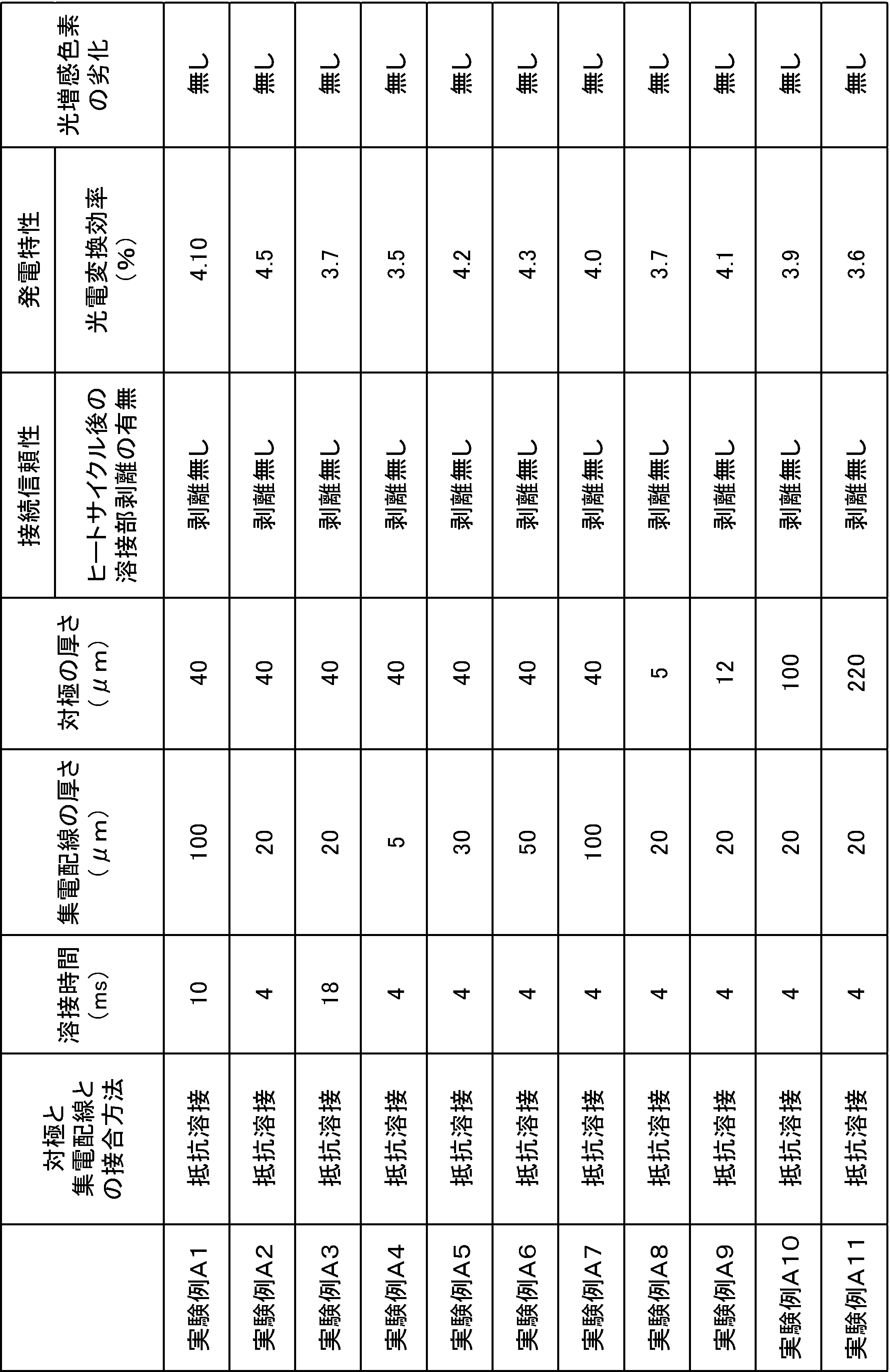
The dye-sensitized solar cell modules obtained in Experimental Examples A1 to A11 were examined for dye deterioration. The deterioration of the photosensitizing dye was judged by the naked eye based on whether or not the color of the photosensitizing dye changed before and after bonding. When the color was clearly changed, it was determined that there was deterioration.
表2に示すように、実験例A1~A11で得られた色素増感太陽電池モジュールは、導電性、接続信頼性、および光増感色素の劣化防止効果のいずれについても良好であった。
As shown in Table 2, the dye-sensitized solar cell modules obtained in Experimental Examples A1 to A11 were good in all of conductivity, connection reliability, and the effect of preventing deterioration of the photosensitizing dye.
以上より、直列且つ電気的に接続される複数の色素増感太陽電池を含む色素増感太陽電池モジュールユニットを有する色素増感太陽電池モジュールの製造方法において、複数の色素増感太陽電池を準備する準備工程と、複数の色素増感太陽電池を直列且つ電気的に接続して色素増感太陽電池モジュールユニットを製造する接続工程とを含み、準備工程において、前記色素増感太陽電池が前記第1電極に設けられた端子部をさらに有し、複数の色素増感太陽電池における透明基板として1つの透明基板が共通に用いられ、接続工程において、隣り合う2つの色素増感太陽電池のうち一方の色素増感太陽電池の第2電極と、他方の色素増感太陽電池の第1電極に設けられる端子部とを抵抗溶接により接続する色素増感太陽電池モジュールの製造方法によれば、優れた導電性及び接続信頼性を有し、光増感色素の劣化が十分に抑制された色素増感太陽電池モジュールを製造できることが確認された。
As described above, a plurality of dye-sensitized solar cells are prepared in a method of manufacturing a dye-sensitized solar cell module having a dye-sensitized solar cell module unit including a plurality of dye-sensitized solar cells connected in series and electrically. A preparation step and a connection step of manufacturing a dye-sensitized solar cell module unit by connecting a plurality of dye-sensitized solar cells in series and electrically, and in the preparation step, the dye-sensitized solar cell is the first step. A terminal portion provided on the electrode is further provided, and one transparent substrate is commonly used as a transparent substrate in the plurality of dye-sensitized solar cells, and one of two adjacent dye-sensitized solar cells is used in the connecting step. Manufacture of a dye-sensitized solar cell module in which a second electrode of a dye-sensitized solar cell and a terminal portion provided on the first electrode of the other dye-sensitized solar cell are connected by resistance welding. According to the law, which has excellent conductivity and connection reliability, deterioration of the photosensitizing dye that is capable of producing a dye-sensitized solar cell module which is sufficiently suppressed confirmed.
(実験例B)
まず表面の寸法が500mm×500mmで厚さ4mmのガラスからなる透明基板の表面上に、FTOからなる厚さ1μmの透明導電膜を形成してなる透明導電性基板を用意した。そして、透明導電膜に対しレーザ加工を行って、234.4mm×116.6mmの矩形領域が2列×4個形成されるようにした。このとき、隣り合う矩形領域間の間隔は1.2mmとなるようにした。 (Experiment B)
First, a transparent conductive substrate prepared by forming a transparent conductive film having a thickness of 1 μm made of FTO on the surface of a transparent substrate made of glass having a surface dimension of 500 mm × 500 mm and a thickness of 4 mm was prepared. Then, laser processing was performed on the transparent conductive film to form 2 × 4 rectangular regions of 234.4 mm × 116.6 mm. At this time, the interval between adjacent rectangular regions was set to 1.2 mm.
次に、透明導電膜の各矩形領域上に、チタニアを含む酸化物半導体層形成用ペーストを、図9に示すパターンとなるように20箇所に塗布し乾燥させた。このとき、ランド部を形成するため、4箇所には、幅10.8mm×長さ107.0mmの寸法で酸化物半導体層形成用ペーストを塗布し、残りの16箇所には幅10.8mm×長さ112.4mmの寸法で酸化物半導体層形成用ペーストを塗布した。
Next, an oxide semiconductor layer forming paste containing titania was applied to each rectangular region of the transparent conductive film at 20 locations so as to form the pattern shown in FIG. At this time, in order to form the land portion, the paste for forming the oxide semiconductor layer is applied to the four places with a width of 10.8 mm × length of 107.0 mm, and the remaining 16 places have a width of 10.8 mm × The oxide semiconductor layer forming paste was applied with a length of 112.4 mm.
次いで、塗布した酸化物半導体層形成用ペーストを、500℃で1時間焼成した。
Next, the applied paste for forming an oxide semiconductor layer was baked at 500 ° C. for 1 hour.
次に、透明導電膜の上に、図9に示すように、外周部と、外周部の内側開口を仕切る仕切り部と、外周部の内側に延びるランド部とを有する集電配線パターンを形成した。このとき、図5に示す接続端子も同時に形成した。また集電配線の厚さ、外周部の幅、仕切り部の幅、外周部からのランド部の長さ及び接続端子の寸法はそれぞれ以下の通りとした。
集電配線の厚さ:0.02mm
外周部の幅:1.7mm
仕切り部の幅:0.3mm
外周部からのランド部の長さ:7.1mm
接続端子の寸法(外周部から外側への突出部分の寸法):5.6mm×6.6mm Next, on the transparent conductive film, as shown in FIG. 9, a current collection wiring pattern having an outer peripheral portion, a partition portion for partitioning the inner opening of the outer peripheral portion, and a land portion extending inside the outer peripheral portion was formed. . At this time, the connection terminals shown in FIG. 5 were also formed. The thickness of the current collector wiring, the width of the outer peripheral portion, the width of the partition portion, the length of the land portion from the outer peripheral portion, and the dimensions of the connection terminal were as follows.
Current collector wiring thickness: 0.02 mm
Width of outer periphery: 1.7mm
Partition width: 0.3mm
Land length from outer periphery: 7.1 mm
Connection terminal dimensions (dimensions of the protruding portion from the outer periphery to the outside): 5.6 mm × 6.6 mm
こうして酸化物半導体層を有する作用極を得た。
Thus, a working electrode having an oxide semiconductor layer was obtained.
次に、封止部を準備した。封止部は、470mm×470mm×50μmのニュクレルからなる1枚の封止用樹脂フィルムを用意し、その封止用樹脂フィルムに、酸化物半導体層の数と同数の四角形状の開口を形成することによって得た。このとき、各開口は、開口の内周と酸化物半導体層の外周との間隔が0.2mmとなるように形成した。こうして、幅が1.7mmの封止部を得た。このとき、封止部の一辺に、ランド部を露出させるように4つの凹部が形成されるようにした。
Next, a sealing part was prepared. For the sealing portion, a single sealing resin film made of 470 mm × 470 mm × 50 μm nucler is prepared, and the same number of rectangular openings as the number of oxide semiconductor layers are formed in the sealing resin film. Was obtained by At this time, each opening was formed so that the distance between the inner periphery of the opening and the outer periphery of the oxide semiconductor layer was 0.2 mm. Thus, a sealing portion having a width of 1.7 mm was obtained. At this time, four concave portions were formed on one side of the sealing portion so as to expose the land portion.
そして、この封止部を、集電配線の上に載せた後、封止部を加熱溶融させることによって集電配線に接着させた。
And after putting this sealing part on current collection wiring, it was made to adhere to current collection wiring by heating and melting a sealing part.
次に、作用極を、N719からなる光増感色素を0.3mMの濃度で含むアセトニトリルおよびtert-ブタノールからなる色素溶液中に一昼夜浸漬させた後、取り出して乾燥させ、酸化物半導体層に光増感色素を担持させた。
Next, the working electrode was immersed overnight in a dye solution consisting of acetonitrile and tert-butanol containing a photosensitizing dye consisting of N719 at a concentration of 0.3 mM, then taken out and dried, and light was applied to the oxide semiconductor layer. A sensitizing dye was supported.
次に、8枚の対極を用意した。各対極は以下のようにして作製した。すなわちまず、234.4mm×122.2mm×40μmのチタン箔を用意し、チタン箔の上にスパッタリング法によって厚さ100nmの白金からなる触媒層を形成した。こうして対極用積層体を用意した。
Next, 8 counter electrodes were prepared. Each counter electrode was produced as follows. That is, first, a 234.4 mm × 122.2 mm × 40 μm titanium foil was prepared, and a catalyst layer made of platinum having a thickness of 100 nm was formed on the titanium foil by a sputtering method. Thus, a laminate for the counter electrode was prepared.
次に、この対極用積層体を、レーザ切断により、図5に示すように、矩形状の本体部の長辺から4つの突起部が突出し、反対側の長辺に4つの切欠きが形成された形状となるように加工した。このとき、本体部、突出部、切欠きの寸法はそれぞれ以下のようにした。
本体部:長辺234.4mm、短辺116.6mm
突出部:幅6.6mm、本体部の長辺からの先端までの長さ5.6mm
切欠き:幅9.0mm、本体部の長辺からの切欠きの底辺までの長さ5.4mm Next, as shown in FIG. 5, this laminate for a counter electrode is cut by laser so that four protrusions protrude from the long side of the rectangular main body, and four cutouts are formed on the opposite long side. It was processed so as to have a different shape. At this time, the dimensions of the main body portion, the protruding portion, and the notch were as follows.
Main body: Long side 234.4 mm, short side 116.6 mm
Protruding part: 6.6mm in width, 5.6mm in length from the long side of the main part to the tip
Notch: Width 9.0mm, Length from long side of main body to bottom of notch 5.4mm
次に、こうして得られた8枚の対極をそれぞれ、封止部の各開口を塞ぐように貼り合わせた。このとき、突出部は、隣の作用極のランド部に対向させ、対極の切欠きは、対極を貼り合わせる作用極のランド部に対向させるようにした。
Next, the eight counter electrodes obtained in this way were bonded together so as to block each opening of the sealing portion. At this time, the projecting portion was made to face the land portion of the adjacent working electrode, and the notch of the counter electrode was made to face the land portion of the working electrode to which the counter electrode was bonded.
そして、対極の突出部は、隣の色素増感太陽電池の集電配線におけるランド部に抵抗溶接により接合した。抵抗溶接は、2本の電極のうち1本の電極を集電配線に接触させ、もう1本の電極を突出部の上から押し当て、1kAの電流を10msの間印加することにより行った。
And the protrusion part of the counter electrode was joined to the land part in the current collection wiring of the adjacent dye-sensitized solar cell by resistance welding. Resistance welding was performed by bringing one of the two electrodes into contact with the current collector wiring, pressing the other electrode from above the protrusion, and applying a current of 1 kA for 10 ms.
こうして、図5に示すように、4個の色素増感太陽電池が直列接続された2列の色素増感太陽電池モジュールユニット300A,300Bを得た。
Thus, as shown in FIG. 5, two rows of dye-sensitized solar cell module units 300A and 300B in which four dye-sensitized solar cells were connected in series were obtained.
次に、416mm×10mm×100μmの寸法のCuからなるCuテープを用意し、このCuテープの一端を色素増感太陽電池50Eの接続端子370に接続し、Cuテープの他端を、色素増感太陽電池50Dの対極の突出部23に抵抗溶接によって接続した。こうして色素増感太陽電池モジュールを得た。このときの抵抗溶接は、対極の突出部と、隣の色素増感太陽電池の集電配線におけるランド部との抵抗溶接と同様の条件で行った。
Next, a Cu tape made of Cu having dimensions of 416 mm × 10 mm × 100 μm is prepared, one end of the Cu tape is connected to the connection terminal 370 of the dye-sensitized solar cell 50E, and the other end of the Cu tape is dye-sensitized. It connected to the protrusion part 23 of the counter electrode of the solar cell 50D by resistance welding. Thus, a dye-sensitized solar cell module was obtained. Resistance welding at this time was performed under the same conditions as resistance welding between the protruding portion of the counter electrode and the land portion in the current collecting wiring of the adjacent dye-sensitized solar cell.
実験例Bで得られた色素増感太陽電池モジュールについて、開口率を測定した。結果を表3に示す。なお、開口率は85%以上であれば合格とし、85%未満であれば不合格とした。

For the dye-sensitized solar cell module obtained in Experimental Example B, the aperture ratio was measured. The results are shown in Table 3. In addition, if the aperture ratio was 85% or more, it was considered acceptable, and if it was less than 85%, it was rejected.
また実験例Bの色素増感太陽電池モジュールについて、接続信頼性を調べた。接続信頼性は、JIS C8938 A-1に定義された温度サイクル試験を200サイクル行い,評価を行った。結果を表3に示す。なお、突出部とランド部との接合部である溶接部の剥離の有無を評価項目とし、剥離の無いものを合格とした。
Also, connection reliability of the dye-sensitized solar cell module of Experimental Example B was examined. Connection reliability was evaluated by performing 200 cycles of the temperature cycle test defined in JIS C8938 A-1. The results are shown in Table 3. In addition, the presence or absence of the peeling of the welding part which is a junction part of a protrusion part and a land part was made into the evaluation item, and the thing without peeling was set as the pass.
表3に示すように、実験例Bで得られた色素増感太陽電池モジュールは、開口率及び接続信頼性のいずれについても合格基準に達していた。
As shown in Table 3, the dye-sensitized solar cell module obtained in Experimental Example B reached the acceptance criteria for both the aperture ratio and the connection reliability.
以上より、直列且つ電気的に接続される複数の色素増感太陽電池を含む色素増感太陽電池モジュールユニットを有する色素増感太陽電池モジュールにおいて、複数の色素増感太陽電池における透明基板として1つの透明基板が共通に用いられ、封止部の外側に凹部が設けられ、隣り合う2つの色素増感太陽電池において、一方の色素増感太陽電池の前記第1電極を含む第1電極部及び前記第2電極を含む第2電極部のうち一方の電極部が、本体部と、前記本体部と導通し、前記本体部における他方の色素増感太陽電池側の縁部の一部から突出する少なくとも1つの突出部とを有し、前記突出部が、前記他方の色素増感太陽電池の前記凹部において、前記他方の色素増感太陽電池の前記第1電極部及び前記第2電極部のうち他方の電極部に接合されている色素増感太陽電池モジュールによれば、十分に大きな開口率を有しながら優れた接続信頼性を有することが確認された。
As described above, in the dye-sensitized solar cell module having the dye-sensitized solar cell module unit including a plurality of dye-sensitized solar cells connected in series and electrically, one transparent substrate in the plurality of dye-sensitized solar cells is used. A transparent substrate is used in common, a recess is provided outside the sealing portion, and in two adjacent dye-sensitized solar cells, the first electrode portion including the first electrode of one dye-sensitized solar cell and the At least one electrode portion of the second electrode portion including the second electrode is electrically connected to the main body portion and the main body portion, and protrudes from a part of the edge of the main body portion on the other dye-sensitized solar cell side. One protruding portion, and the protruding portion is the other of the first electrode portion and the second electrode portion of the other dye-sensitized solar cell in the concave portion of the other dye-sensitized solar cell. In contact with the electrode According to the dye-sensitized solar cell module which is, it was confirmed that excellent connection reliability while having a large aperture ratio sufficiently.
10…作用極
11…透明基板
12…透明導電膜
13…酸化物半導体層
14…集電配線(第1電極部)
14c…ランド部(端子部)
15…透明導電性基板(第1電極、第1電極部)
20…対極(第2電極、第2電極部)
20a…対極のうち電解質に対向する部分
21…金属基板
23…突出部
30…封止部
50,50A~50H…色素増感太陽電池
60,260,460…接続部材(第2電極部)
65,365,465,565…合金部
300A,300B…色素増感太陽電池モジュールユニット
100,200,300,400,500,600…色素増感太陽電池モジュール
510…インサート材(端子部) DESCRIPTION OFSYMBOLS 10 ... Working electrode 11 ... Transparent substrate 12 ... Transparent electrically conductive film 13 ... Oxide semiconductor layer 14 ... Current collection wiring (1st electrode part)
14c Land part (terminal part)
15 ... Transparent conductive substrate (first electrode, first electrode portion)
20 ... Counter electrode (second electrode, second electrode part)
20a: a portion of the counter electrode facing theelectrolyte 21 ... a metal substrate 23 ... a protruding portion 30 ... a sealing portion 50, 50A to 50H ... a dye-sensitized solar cell 60, 260, 460 ... a connecting member (second electrode portion)
65, 365, 465, 565 ... Alloy part 300A, 300B ... Dye-sensitized solar cell module unit 100, 200, 300, 400, 500, 600 ... Dye-sensitized solar cell module 510 ... Insert material (terminal part)
11…透明基板
12…透明導電膜
13…酸化物半導体層
14…集電配線(第1電極部)
14c…ランド部(端子部)
15…透明導電性基板(第1電極、第1電極部)
20…対極(第2電極、第2電極部)
20a…対極のうち電解質に対向する部分
21…金属基板
23…突出部
30…封止部
50,50A~50H…色素増感太陽電池
60,260,460…接続部材(第2電極部)
65,365,465,565…合金部
300A,300B…色素増感太陽電池モジュールユニット
100,200,300,400,500,600…色素増感太陽電池モジュール
510…インサート材(端子部) DESCRIPTION OF
14c Land part (terminal part)
15 ... Transparent conductive substrate (first electrode, first electrode portion)
20 ... Counter electrode (second electrode, second electrode part)
20a: a portion of the counter electrode facing the
65, 365, 465, 565 ...
Claims (13)
- 透明基板及び前記透明基板上に設けられる透明導電膜を有する第1電極、並びに、不動態膜を形成する金属からなる金属基板を含む第2電極を準備する準備工程と、
前記第1電極又は前記第2電極上に酸化物半導体層を形成する酸化物半導体層形成工程と、
前記酸化物半導体層に光増感色素を担持する色素担持工程と、
前記酸化物半導体層上に電解質を配置する電解質配置工程と、
前記第1電極と前記第2電極とを対向させて封止部により前記電解質を封止する封止工程と、
前記第2電極の前記金属基板上であって前記第1電極と反対側の表面に前記金属基板よりも低い抵抗を有する金属からなる接続部材を固定する接続部材固定工程とを含み、
前記接続部材固定工程において、前記接続部材を抵抗溶接により前記金属基板に接合することにより前記金属基板上に前記接続部材を固定する、色素増感太陽電池の製造方法。 A preparatory step of preparing a first electrode having a transparent substrate and a transparent conductive film provided on the transparent substrate, and a second electrode including a metal substrate made of a metal forming a passive film;
An oxide semiconductor layer forming step of forming an oxide semiconductor layer on the first electrode or the second electrode;
A dye carrying step of carrying a photosensitizing dye on the oxide semiconductor layer;
An electrolyte disposing step of disposing an electrolyte on the oxide semiconductor layer;
A sealing step of sealing the electrolyte by a sealing portion with the first electrode and the second electrode facing each other;
A connection member fixing step of fixing a connection member made of a metal having a lower resistance than the metal substrate on the surface of the second electrode opposite to the first electrode on the metal substrate;
The method for manufacturing a dye-sensitized solar cell, wherein in the connecting member fixing step, the connecting member is bonded to the metal substrate by resistance welding to fix the connecting member on the metal substrate. - 前記接続部材固定工程において、抵抗溶接を、前記金属基板の上に前記接続部材を接触させた状態で、2つの電極をそれぞれ、前記接続部材の表面、及び、前記金属基板の表面に当接させることによって行う、請求項1に記載の色素増感太陽電池の製造方法。 In the connecting member fixing step, in resistance welding, the two electrodes are brought into contact with the surface of the connecting member and the surface of the metal substrate, respectively, with the connecting member in contact with the metal substrate. The manufacturing method of the dye-sensitized solar cell of Claim 1 performed by.
- 前記接続部材固定工程において、抵抗溶接を1~20ms行う、請求項1又は2記載の色素増感太陽電池の製造方法。 3. The method for producing a dye-sensitized solar cell according to claim 1, wherein resistance welding is performed for 1 to 20 ms in the connecting member fixing step.
- 直列且つ電気的に接続される複数の色素増感太陽電池を含む色素増感太陽電池モジュールユニットを有する色素増感太陽電池モジュールの製造方法において、
前記複数の色素増感太陽電池を準備する準備工程と、
前記複数の色素増感太陽電池を直列且つ電気的に接続して前記色素増感太陽電池モジュールユニットを製造する接続工程とを含み、
前記準備工程において、前記複数の色素増感太陽電池のうちの少なくとも一部の色素増感太陽電池が、請求項1~3のいずれか一項に記載の色素増感太陽電池の製造方法により準備され、前記色素増感太陽電池が前記第1電極に設けられた端子部をさらに有し、前記複数の色素増感太陽電池における前記透明基板として1つの透明基板が共通に用いられ、
前記接続工程において、隣り合う2つの色素増感太陽電池のうち一方の色素増感太陽電池の前記第2電極と、他方の色素増感太陽電池の前記第1電極に設けられた前記端子部とを抵抗溶接により接続する、色素増感太陽電池モジュールの製造方法。 In a method for producing a dye-sensitized solar cell module having a dye-sensitized solar cell module unit including a plurality of dye-sensitized solar cells connected in series and electrically,
A preparation step of preparing the plurality of dye-sensitized solar cells;
Connecting the plurality of dye-sensitized solar cells in series and electrically to produce the dye-sensitized solar cell module unit,
In the preparation step, at least some of the plurality of dye-sensitized solar cells are prepared by the method for manufacturing a dye-sensitized solar cell according to any one of claims 1 to 3. The dye-sensitized solar cell further has a terminal portion provided on the first electrode, and one transparent substrate is commonly used as the transparent substrate in the plurality of dye-sensitized solar cells,
In the connecting step, of the two dye-sensitized solar cells adjacent to each other, the second electrode of one dye-sensitized solar cell, and the terminal portion provided on the first electrode of the other dye-sensitized solar cell; A method for manufacturing a dye-sensitized solar cell module, in which the components are connected by resistance welding. - 前記接続工程において、前記抵抗溶接を、前記端子部の上に前記第2電極を接触させた状態で、2つの抵抗溶接用の電極を、前記第2電極の前記金属基板のうち前記第1電極と反対側の表面に当接させることによって行う、請求項4に記載の色素増感太陽電池モジュールの製造方法。 In the connecting step, the resistance welding is performed in a state where the second electrode is in contact with the terminal portion, and the two electrodes for resistance welding are connected to the first electrode of the metal substrate of the second electrode. The manufacturing method of the dye-sensitized solar cell module of Claim 4 performed by making it contact | abut on the surface on the opposite side.
- 複数の色素増感太陽電池を直列且つ電気的に接続してなる色素増感太陽電池モジュールの製造方法において、
前記複数の色素増感太陽電池を直列且つ電気的に接続する接続工程を含み、
前記色素増感太陽電池を請求項1~3のいずれか一項に記載の色素増感太陽電池の製造方法によって製造し、
前記接続工程において、隣り合う2つの色素増感太陽電池のうち一方の色素増感太陽電池の前記第2電極に設けられた前記接続部材と、他方の色素増感太陽電池の前記第1電極に設けられた端子部とを接続する色素増感太陽電池モジュールの製造方法。 In the method for producing a dye-sensitized solar cell module in which a plurality of dye-sensitized solar cells are electrically connected in series,
A connection step of electrically connecting the plurality of dye-sensitized solar cells in series and
The dye-sensitized solar cell is produced by the method for producing a dye-sensitized solar cell according to any one of claims 1 to 3,
In the connecting step, the connecting member provided on the second electrode of one dye-sensitized solar cell of two adjacent dye-sensitized solar cells and the first electrode of the other dye-sensitized solar cell. The manufacturing method of the dye-sensitized solar cell module which connects the provided terminal part. - 前記接続工程において、隣り合う2つの色素増感太陽電池のうち一方の色素増感太陽電池の前記第2電極に設けられた前記接続部材と、他方の色素増感太陽電池の前記第1電極に設けられた端子部とを抵抗溶接により接続し、前記抵抗溶接を、前記端子部の上に前記接続部材を接触させた状態で、2つの抵抗溶接用の電極を、前記接続部材の表面に当接させることによって行う、請求項6に記載の色素増感太陽電池モジュールの製造方法。 In the connecting step, the connecting member provided on the second electrode of one dye-sensitized solar cell of two adjacent dye-sensitized solar cells and the first electrode of the other dye-sensitized solar cell. The terminal portion provided is connected by resistance welding, and the resistance welding is performed in a state where the connection member is in contact with the terminal portion, and two resistance welding electrodes are applied to the surface of the connection member. The manufacturing method of the dye-sensitized solar cell module of Claim 6 performed by making it contact.
- 前記接続工程において、前記抵抗溶接を1~20ms行う、請求項4、5及び7のいずれか一項に記載の色素増感太陽電池モジュールの製造方法。 The method for producing a dye-sensitized solar cell module according to any one of claims 4, 5, and 7, wherein the resistance welding is performed for 1 to 20 ms in the connection step.
- 透明基板及び前記透明基板上に設けられる透明導電膜を有する第1電極と、
前記第1電極に対向し、不動態膜を形成する金属からなる金属基板を含む第2電極と、
前記第1電極又は前記第2電極上に設けられる酸化物半導体層と、
前記第1電極と前記第2電極との間に設けられる電解質と、
前記第1電極及び前記第2電極を接合させる封止部と、
前記第2電極のうち前記第1電極と反対側の表面に設けられ、前記金属基板を構成する金属よりも低い抵抗を有する金属からなる接続部材とを備えており、
前記第2電極と前記接続部材との間に、前記金属基板を構成する金属と前記接続部材を構成する金属との合金からなる合金部が設けられている、色素増感太陽電池。 A first electrode having a transparent substrate and a transparent conductive film provided on the transparent substrate;
A second electrode including a metal substrate made of a metal facing the first electrode and forming a passive film;
An oxide semiconductor layer provided on the first electrode or the second electrode;
An electrolyte provided between the first electrode and the second electrode;
A sealing portion for joining the first electrode and the second electrode;
A connection member made of a metal having a lower resistance than the metal constituting the metal substrate, provided on the surface of the second electrode opposite to the first electrode;
A dye-sensitized solar cell, wherein an alloy part made of an alloy of a metal constituting the metal substrate and a metal constituting the connection member is provided between the second electrode and the connection member. - 前記接続部材が、前記第2金属のうち前記電解質に対向する部分に設けられている、請求項9に記載の色素増感太陽電池。 The dye-sensitized solar cell according to claim 9, wherein the connecting member is provided in a portion of the second metal facing the electrolyte.
- 直列且つ電気的に接続される複数の色素増感太陽電池を含む色素増感太陽電池モジュールユニットを有する色素増感太陽電池モジュールにおいて、
前記複数の色素増感太陽電池のうちの少なくとも一部の色素増感太陽電池が、請求項9又は10に記載の色素増感太陽電池で構成され、
前記色素増感太陽電池が、前記第1電極に設けられた端子部をさらに有し、
前記複数の色素増感太陽電池における前記透明基板として1つの透明基板が共通に用いられ、
隣り合う2つの色素増感太陽電池のうち一方の色素増感太陽電池の前記第2電極の前記金属基板と、他方の色素増感太陽電池の前記第1電極に設けられた前記端子部とが直接接続され、前記端子部のうち前記金属基板と接触している部分が、前記第2電極の前記金属基板よりも低い抵抗を有する金属で構成され、
前記端子部と前記第2電極との間に、前記金属基板を構成する金属と前記端子部のうち前記金属基板と接触している部分を構成する金属との合金からなる合金部が設けられている、色素増感太陽電池モジュール。 In a dye-sensitized solar cell module having a dye-sensitized solar cell module unit including a plurality of dye-sensitized solar cells connected in series and electrically,
The dye-sensitized solar cell of at least a part of the plurality of dye-sensitized solar cells is constituted by the dye-sensitized solar cell according to claim 9 or 10,
The dye-sensitized solar cell further has a terminal portion provided on the first electrode,
One transparent substrate is commonly used as the transparent substrate in the plurality of dye-sensitized solar cells,
Of the two adjacent dye-sensitized solar cells, the metal substrate of the second electrode of one dye-sensitized solar cell and the terminal portion provided on the first electrode of the other dye-sensitized solar cell. Directly connected, the portion of the terminal portion that is in contact with the metal substrate is made of a metal having a lower resistance than the metal substrate of the second electrode,
Between the terminal portion and the second electrode, an alloy portion made of an alloy of a metal constituting the metal substrate and a metal constituting a portion of the terminal portion in contact with the metal substrate is provided. Dye-sensitized solar cell module. - 直列且つ電気的に接続される複数の色素増感太陽電池を含む色素増感太陽電池モジュールユニットを有する色素増感太陽電池モジュールにおいて、
前記複数の色素増感太陽電池のうちの少なくとも一部の色素増感太陽電池が、請求項9又は10に記載の色素増感太陽電池で構成され、
前記色素増感太陽電池が、前記第1電極に設けられた端子部をさらに有し、
前記複数の色素増感太陽電池における前記透明基板として1つの透明基板が共通に用いられ、
隣り合う2つの色素増感太陽電池のうち一方の色素増感太陽電池の前記第2電極に固定された前記接続部材と、他方の色素増感太陽電池の前記第1電極に設けられた前記端子部とが直接接続され、
前記端子部と前記接続部材との間に、前記端子部のうち前記接続部材と接触している部分を構成する金属と前記接続部材を構成する金属との合金からなる合金部が設けられている、色素増感太陽電池モジュール。 In a dye-sensitized solar cell module having a dye-sensitized solar cell module unit including a plurality of dye-sensitized solar cells connected in series and electrically,
The dye-sensitized solar cell of at least a part of the plurality of dye-sensitized solar cells is constituted by the dye-sensitized solar cell according to claim 9 or 10,
The dye-sensitized solar cell further has a terminal portion provided on the first electrode,
One transparent substrate is commonly used as the transparent substrate in the plurality of dye-sensitized solar cells,
Of the two adjacent dye-sensitized solar cells, the connection member fixed to the second electrode of one dye-sensitized solar cell, and the terminal provided to the first electrode of the other dye-sensitized solar cell Connected directly to the
Between the terminal part and the connection member, an alloy part made of an alloy of a metal that constitutes a portion of the terminal part that is in contact with the connection member and a metal that constitutes the connection member is provided. , Dye-sensitized solar cell module. - 直列且つ電気的に接続される複数の色素増感太陽電池を含む色素増感太陽電池モジュールユニットを有する色素増感太陽電池モジュールにおいて、
前記複数の色素増感太陽電池のうちの少なくとも一部の色素増感太陽電池が、請求項9又は10に記載の色素増感太陽電池で構成され、
前記複数の色素増感太陽電池における前記透明基板として1つの透明基板が共通に用いられ、
前記複数の色素増感太陽電池がそれぞれ前記第1電極を含む第1電極部と、前記第2電極を含む第2電極部とを含み、
前記封止部の外側に凹部が設けられ、
隣り合う2つの色素増感太陽電池において、一方の色素増感太陽電池の前記第1電極部及び前記第2電極部のうち一方の電極部が、本体部と、前記本体部と導通し、前記本体部における他方の色素増感太陽電池側の縁部の一部から突出する少なくとも1つの突出部とを有し、
前記突出部が、前記他方の色素増感太陽電池の前記凹部において、前記他方の色素増感太陽電池の前記第1電極部及び前記第2電極部のうち他方の電極部に接合されている色素増感太陽電池モジュール。
In a dye-sensitized solar cell module having a dye-sensitized solar cell module unit including a plurality of dye-sensitized solar cells connected in series and electrically,
The dye-sensitized solar cell of at least a part of the plurality of dye-sensitized solar cells is constituted by the dye-sensitized solar cell according to claim 9 or 10,
One transparent substrate is commonly used as the transparent substrate in the plurality of dye-sensitized solar cells,
Each of the plurality of dye-sensitized solar cells includes a first electrode portion including the first electrode and a second electrode portion including the second electrode;
A recess is provided outside the sealing portion,
In two adjacent dye-sensitized solar cells, one of the first electrode portion and the second electrode portion of one dye-sensitized solar cell is electrically connected to the main body portion and the main body portion, and Having at least one projecting portion projecting from a part of an edge of the main body portion on the other dye-sensitized solar cell side;
The pigment | dye by which the said protrusion part is joined to the other electrode part among the said 1st electrode part of the said other dye-sensitized solar cell, and the said 2nd electrode part in the said recessed part of said other dye-sensitized solar cell. Sensitized solar cell module.
Priority Applications (3)
| Application Number | Priority Date | Filing Date | Title |
|---|---|---|---|
| CN201280003962.1A CN103229350B (en) | 2011-03-02 | 2012-02-28 | Dye-sensitized solar cell, its manufacture method, dye-sensitized solar cell module and its manufacture method |
| EP12752945.1A EP2683021B1 (en) | 2011-03-02 | 2012-02-28 | Dye-sensitized solar cell module and process of manufacturing same |
| US14/015,094 US9330854B2 (en) | 2011-03-02 | 2013-08-30 | Dye-sensitized solar cell and process of manufacturing same, dye-sensitized solar cell module and process of manufacturing same |
Applications Claiming Priority (6)
| Application Number | Priority Date | Filing Date | Title |
|---|---|---|---|
| JP2011044674A JP5762053B2 (en) | 2011-03-02 | 2011-03-02 | Dye-sensitized solar cell, method for producing the same, dye-sensitized solar cell module and method for producing the same |
| JP2011-044674 | 2011-03-02 | ||
| JP2011044677A JP5680996B2 (en) | 2011-03-02 | 2011-03-02 | Dye-sensitized solar cell module and manufacturing method thereof |
| JP2011-044675 | 2011-03-02 | ||
| JP2011-044677 | 2011-03-02 | ||
| JP2011044675A JP5680995B2 (en) | 2011-03-02 | 2011-03-02 | Dye-sensitized solar cell module |
Related Child Applications (1)
| Application Number | Title | Priority Date | Filing Date |
|---|---|---|---|
| US14/015,094 Continuation US9330854B2 (en) | 2011-03-02 | 2013-08-30 | Dye-sensitized solar cell and process of manufacturing same, dye-sensitized solar cell module and process of manufacturing same |
Publications (1)
| Publication Number | Publication Date |
|---|---|
| WO2012118050A1 true WO2012118050A1 (en) | 2012-09-07 |
Family
ID=46757982
Family Applications (1)
| Application Number | Title | Priority Date | Filing Date |
|---|---|---|---|
| PCT/JP2012/054861 WO2012118050A1 (en) | 2011-03-02 | 2012-02-28 | Dye-sensitized solar cell and process of manufacturing same, and dye-sensitized solar cell module and process of manufacturing same |
Country Status (4)
| Country | Link |
|---|---|
| US (1) | US9330854B2 (en) |
| EP (1) | EP2683021B1 (en) |
| CN (1) | CN103229350B (en) |
| WO (1) | WO2012118050A1 (en) |
Cited By (3)
| Publication number | Priority date | Publication date | Assignee | Title |
|---|---|---|---|---|
| JP2014075312A (en) * | 2012-10-05 | 2014-04-24 | Fujikura Ltd | Dye-sensitized solar cell and dye-sensitized solar cell module |
| JP2014075314A (en) * | 2012-10-05 | 2014-04-24 | Fujikura Ltd | Dye-sensitized solar cell and dye-sensitized solar cell module |
| JP2015056294A (en) * | 2013-09-12 | 2015-03-23 | 株式会社フジクラ | Dye-sensitized solar cell element |
Families Citing this family (6)
| Publication number | Priority date | Publication date | Assignee | Title |
|---|---|---|---|---|
| EP3047332A4 (en) * | 2013-09-19 | 2017-04-26 | Polyceed Inc. | Chromatic systems |
| CN104485231A (en) * | 2014-12-18 | 2015-04-01 | 中国科学院上海硅酸盐研究所 | Novel pretreatment method of photo-anode of dye-sensitized solar cell |
| JP6363032B2 (en) * | 2015-02-26 | 2018-07-25 | 株式会社日立情報通信エンジニアリング | Key change direction control system and key change direction control method |
| JPWO2016152393A1 (en) * | 2015-03-23 | 2018-01-18 | 積水化学工業株式会社 | Electronic device using film substrate, dye-sensitized solar cell, and method for manufacturing electronic device |
| JP6323375B2 (en) * | 2015-03-26 | 2018-05-16 | ソニー株式会社 | COMMUNICATION DEVICE, COMMUNICATION SYSTEM, AND COMMUNICATION METHOD |
| CN115298844A (en) * | 2020-03-16 | 2022-11-04 | 株式会社理光 | Photoelectric conversion element, photoelectric conversion module, electronic device, and power supply module |
Citations (8)
| Publication number | Priority date | Publication date | Assignee | Title |
|---|---|---|---|---|
| JP2004303607A (en) * | 2003-03-31 | 2004-10-28 | Fujikura Ltd | Solar cell |
| JP2006049268A (en) * | 2004-08-04 | 2006-02-16 | Korea Electronics Telecommun | Dye-sensitized solar cell module |
| JP2007042526A (en) * | 2005-08-05 | 2007-02-15 | Hitachi Vehicle Energy Ltd | Lithium secondary battery |
| JP2009187768A (en) * | 2008-02-06 | 2009-08-20 | Sony Corp | Nonaqueous electrolyte battery and its manufacturing method |
| JP2009187691A (en) * | 2008-02-04 | 2009-08-20 | Panasonic Corp | Battery pack |
| WO2009133689A1 (en) | 2008-04-28 | 2009-11-05 | 株式会社フジクラ | Manufacturing method for photoelectric transducer, photoelectric transducer manufactured thereby, manufacturing method for photoelectric transducer module, and photoelectric transducer module manufactured thereby |
| WO2009141964A1 (en) * | 2008-04-28 | 2009-11-26 | 株式会社フジクラ | Photoelectric transducer module |
| WO2009144949A1 (en) | 2008-05-30 | 2009-12-03 | 株式会社フジクラ | Photoelectric conversion element module and method for manufacturing photoelectric conversion element module |
Family Cites Families (8)
| Publication number | Priority date | Publication date | Assignee | Title |
|---|---|---|---|---|
| US4340803A (en) * | 1979-11-20 | 1982-07-20 | Rca Corporation | Method for interconnecting solar cells |
| JP3164183B2 (en) | 1993-08-06 | 2001-05-08 | キヤノン株式会社 | Photovoltaic element and module |
| JPH07202241A (en) | 1993-12-28 | 1995-08-04 | Mitsubishi Electric Corp | Solar battery, mounting method and manufacture thereof |
| JP2006060038A (en) * | 2004-08-20 | 2006-03-02 | Agilent Technol Inc | Prober, and testing device using same |
| JP2009110796A (en) * | 2007-10-30 | 2009-05-21 | Sony Corp | Dye-sensitized photoelectric conversion element module, its manufacturing method, and electronic device |
| US20100319751A1 (en) * | 2008-01-30 | 2010-12-23 | Jason Day | Series interconnected thin-film photovoltaic module and method for preparation thereof |
| JP5430970B2 (en) | 2008-04-28 | 2014-03-05 | 株式会社フジクラ | Method for manufacturing photoelectric conversion element and method for manufacturing photoelectric conversion element module |
| JP4778120B1 (en) * | 2011-03-08 | 2011-09-21 | 有限会社ナプラ | Electronics |
-
2012
- 2012-02-28 EP EP12752945.1A patent/EP2683021B1/en not_active Not-in-force
- 2012-02-28 CN CN201280003962.1A patent/CN103229350B/en not_active Expired - Fee Related
- 2012-02-28 WO PCT/JP2012/054861 patent/WO2012118050A1/en active Application Filing
-
2013
- 2013-08-30 US US14/015,094 patent/US9330854B2/en not_active Expired - Fee Related
Patent Citations (8)
| Publication number | Priority date | Publication date | Assignee | Title |
|---|---|---|---|---|
| JP2004303607A (en) * | 2003-03-31 | 2004-10-28 | Fujikura Ltd | Solar cell |
| JP2006049268A (en) * | 2004-08-04 | 2006-02-16 | Korea Electronics Telecommun | Dye-sensitized solar cell module |
| JP2007042526A (en) * | 2005-08-05 | 2007-02-15 | Hitachi Vehicle Energy Ltd | Lithium secondary battery |
| JP2009187691A (en) * | 2008-02-04 | 2009-08-20 | Panasonic Corp | Battery pack |
| JP2009187768A (en) * | 2008-02-06 | 2009-08-20 | Sony Corp | Nonaqueous electrolyte battery and its manufacturing method |
| WO2009133689A1 (en) | 2008-04-28 | 2009-11-05 | 株式会社フジクラ | Manufacturing method for photoelectric transducer, photoelectric transducer manufactured thereby, manufacturing method for photoelectric transducer module, and photoelectric transducer module manufactured thereby |
| WO2009141964A1 (en) * | 2008-04-28 | 2009-11-26 | 株式会社フジクラ | Photoelectric transducer module |
| WO2009144949A1 (en) | 2008-05-30 | 2009-12-03 | 株式会社フジクラ | Photoelectric conversion element module and method for manufacturing photoelectric conversion element module |
Cited By (3)
| Publication number | Priority date | Publication date | Assignee | Title |
|---|---|---|---|---|
| JP2014075312A (en) * | 2012-10-05 | 2014-04-24 | Fujikura Ltd | Dye-sensitized solar cell and dye-sensitized solar cell module |
| JP2014075314A (en) * | 2012-10-05 | 2014-04-24 | Fujikura Ltd | Dye-sensitized solar cell and dye-sensitized solar cell module |
| JP2015056294A (en) * | 2013-09-12 | 2015-03-23 | 株式会社フジクラ | Dye-sensitized solar cell element |
Also Published As
| Publication number | Publication date |
|---|---|
| EP2683021B1 (en) | 2017-06-07 |
| US20140000677A1 (en) | 2014-01-02 |
| CN103229350B (en) | 2016-06-22 |
| US9330854B2 (en) | 2016-05-03 |
| EP2683021A1 (en) | 2014-01-08 |
| EP2683021A4 (en) | 2014-09-03 |
| CN103229350A (en) | 2013-07-31 |
Similar Documents
| Publication | Publication Date | Title |
|---|---|---|
| JP5230481B2 (en) | Photoelectric conversion element | |
| WO2012118050A1 (en) | Dye-sensitized solar cell and process of manufacturing same, and dye-sensitized solar cell module and process of manufacturing same | |
| EP2287961B1 (en) | Photoelectric conversion element module and method for manufacturing photoelectric conversion element module | |
| JP5430971B2 (en) | Method for manufacturing photoelectric conversion element and method for manufacturing photoelectric conversion element module | |
| EP2683020B1 (en) | Dye-sensitized solar cell module | |
| AU2009241138B2 (en) | Manufacturing method for photoelectric transducer, photoelectric transducer manufactured thereby, manufacturing method for photoelectric transducer module, and photoelectric transducer module manufactured thereby | |
| JP5351553B2 (en) | Photoelectric conversion element module | |
| JP2009110796A (en) | Dye-sensitized photoelectric conversion element module, its manufacturing method, and electronic device | |
| JP5451106B2 (en) | Photoelectric conversion element module | |
| JP5680996B2 (en) | Dye-sensitized solar cell module and manufacturing method thereof | |
| JP5412136B2 (en) | Photoelectric conversion element | |
| JP5680995B2 (en) | Dye-sensitized solar cell module | |
| JP5706786B2 (en) | Method for producing dye-sensitized solar cell | |
| JP5969865B2 (en) | Dye-sensitized solar cell module | |
| JP5762053B2 (en) | Dye-sensitized solar cell, method for producing the same, dye-sensitized solar cell module and method for producing the same | |
| JP2010198834A (en) | Method for manufacturing photoelectric conversion element module |
Legal Events
| Date | Code | Title | Description |
|---|---|---|---|
| 121 | Ep: the epo has been informed by wipo that ep was designated in this application |
Ref document number: 12752945 Country of ref document: EP Kind code of ref document: A1 |
|
| NENP | Non-entry into the national phase |
Ref country code: DE |
|
| REEP | Request for entry into the european phase |
Ref document number: 2012752945 Country of ref document: EP |