WO2012110544A1 - Harvester spout control system and method - Google Patents
Harvester spout control system and method Download PDFInfo
- Publication number
- WO2012110544A1 WO2012110544A1 PCT/EP2012/052567 EP2012052567W WO2012110544A1 WO 2012110544 A1 WO2012110544 A1 WO 2012110544A1 EP 2012052567 W EP2012052567 W EP 2012052567W WO 2012110544 A1 WO2012110544 A1 WO 2012110544A1
- Authority
- WO
- WIPO (PCT)
- Prior art keywords
- harvester
- spout
- distance
- lateral
- transport vehicle
- Prior art date
Links
Images


Classifications
-
- A—HUMAN NECESSITIES
- A01—AGRICULTURE; FORESTRY; ANIMAL HUSBANDRY; HUNTING; TRAPPING; FISHING
- A01D—HARVESTING; MOWING
- A01D43/00—Mowers combined with apparatus performing additional operations while mowing
- A01D43/06—Mowers combined with apparatus performing additional operations while mowing with means for collecting, gathering or loading mown material
- A01D43/07—Mowers combined with apparatus performing additional operations while mowing with means for collecting, gathering or loading mown material in or into a trailer
- A01D43/073—Mowers combined with apparatus performing additional operations while mowing with means for collecting, gathering or loading mown material in or into a trailer with controllable discharge spout
-
- A—HUMAN NECESSITIES
- A01—AGRICULTURE; FORESTRY; ANIMAL HUSBANDRY; HUNTING; TRAPPING; FISHING
- A01D—HARVESTING; MOWING
- A01D41/00—Combines, i.e. harvesters or mowers combined with threshing devices
- A01D41/12—Details of combines
- A01D41/127—Control or measuring arrangements specially adapted for combines
-
- A—HUMAN NECESSITIES
- A01—AGRICULTURE; FORESTRY; ANIMAL HUSBANDRY; HUNTING; TRAPPING; FISHING
- A01D—HARVESTING; MOWING
- A01D43/00—Mowers combined with apparatus performing additional operations while mowing
- A01D43/08—Mowers combined with apparatus performing additional operations while mowing with means for cutting up the mown crop, e.g. forage harvesters
- A01D43/086—Mowers combined with apparatus performing additional operations while mowing with means for cutting up the mown crop, e.g. forage harvesters and means for collecting, gathering or loading mown material
- A01D43/087—Mowers combined with apparatus performing additional operations while mowing with means for cutting up the mown crop, e.g. forage harvesters and means for collecting, gathering or loading mown material with controllable discharge spout
-
- A—HUMAN NECESSITIES
- A01—AGRICULTURE; FORESTRY; ANIMAL HUSBANDRY; HUNTING; TRAPPING; FISHING
- A01F—PROCESSING OF HARVESTED PRODUCE; HAY OR STRAW PRESSES; DEVICES FOR STORING AGRICULTURAL OR HORTICULTURAL PRODUCE
- A01F12/00—Parts or details of threshing apparatus
- A01F12/46—Mechanical grain conveyors
Definitions
- the present application relates generally to a control system and method for a harvester spout.
- the present application relates more specifically to a control system and method to control the operation or position of the harvester spout during "unload on the go" operation of the harvester.
- Harvesters or harvesting machines pick up crop material, treat the crop material, e.g., remove any undesirable portions or residue, and discharge the crop material.
- Harvesters can discharge the crop material, either continuously as with a forage harvester or after intermediate storage as with a combine harvester, to a transport or transfer vehicle.
- the transport vehicle may be a tractor or truck pulling a cart, wagon, or trailer, or a truck or other vehicle capable of transporting harvested crop material.
- the harvested crop material is loaded into the transport vehicle via a crop discharging or unloading device, such as a spout or discharge auger, associated with the harvester.
- Unload on the go operation of the harvester the harvested crop material is transferred from the harvester to the transport vehicle while both vehicles are moving.
- the transport vehicle can travel next to and/or behind the harvester during unload on the go operation.
- Unload on the go operation is required for a forage harvester, since the forage harvester constantly discharges the harvested crop material. While unload on the go operation is not required for a combine harvester due to the combine harvester's intermediate storage capability, unload on the go operation is commonly used for a combine harvester to maximize the operating efficiency of the combine harvester.
- the operation of the harvester and transport vehicle is coordinated to maintain the relative distance between the harvester and transport vehicle within an acceptable range.
- the position and orientation of the harvester unload spout and the position of the transport vehicle, specifically the portion of the transport vehicle receiving crop material, relative to the harvester unload spout position are maintained within an acceptable distance range to permit harvester unload on the go operation, i.e., the discharged crop material can be provided into the transport vehicle without loss to the ground. That is, discharged crop material is directed to collect in the transport vehicle and is substantially prevented from being misdirected to miss the transport vehicle and collecting on the ground resulting in waste or loss of crop material.
- both the lateral (side to side) distance and longitudinal (fore and aft) distance between the harvester and transport vehicle have to be maintained within acceptable ranges.
- GPS global positioning system
- each machine can communicate its corresponding position provided by the GPS system to the other machine.
- a master machine such as a harvester
- the slave machine such as a transport vehicle
- the longitudinal distance of the two machines can be controlled to be within an acceptable range during normal unload on the go operation.
- the GPS based auto-guidance system may not be able to maintain an acceptable distance range between the harvester and the transport vehicle in the event of an unexpected field condition that results in a sudden speed change or position change of one or both of the harvester and transport vehicle.
- position synchronization between the harvester and transport vehicle can be broken by unexpected field conditions because the speed adjustment or position adjustment by the auto-guidance system may not occur quickly enough in order to prevent harvested crop material from dropping onto the ground.
- Some examples of unexpected field conditions that may occur during an unload on the go operation include obstacles, unexpected animals, stones, a furrow or washed out spot, a circle irrigation wheel rut, etc.
- the present application is directed to a GPS based control system and method to prevent harvester crop material loss caused by sudden speed changes or position changes of either or both of the harvester or the transport vehicle during harvester unload on the go operations.
- a method of controlling operation of an unload spout of a moving harvester used to supply crop material to an associated transport vehicle as set forth in claim 1 of the appended claims.
- the second controller further predicts a distance deviation of the predicted lateral distance from a normal lateral distance and a distance deviation of the predicted longitudinal distance from a normal longitudinal distance.
- the normal lateral and longitudinal distances can be the lateral and longitudinal distances between the harvester and transport vehicle when the two vehicles are ideally aligned for unload on the go operation with the harvester spout at a zero-adjustment configuration and crop material is discharged to the centre area of the loading receptacle.
- the magnitudes of the predicted lateral and longitudinal distance deviations can be used as a basis of how much and/or how fast to adjust an operational configuration of the harvester spout.
- the second controller may transmit a second control signal to return the operational configuration of the harvester spout to a prior operational configuration in response to the predicted lateral and longitudinal distances being within the corresponding predetermined lateral and longitudinal distance ranges.
- the transmitted control signal from the second controller may stop operation of the harvester spout.
- the control system may further comprise a third controller comprising a microprocessor to execute a computer program to transmit a second control signal to adjust an orientation of the harvester spout in response to receiving the control signal and the predicted lateral and longitudinal distance deviations from the second controller.
- a third controller comprising a microprocessor to execute a computer program to transmit a second control signal to adjust an orientation of the harvester spout in response to receiving the control signal and the predicted lateral and longitudinal distance deviations from the second controller.
- the transmitted second control signal from the third controller may rotate the harvester spout.
- the transmitted second control signal from the third controller may adjust a rotational position of a boot connected to the harvester spout.
- the transmitted second control signal from the third controller may adjust a lateral position of a boot connected to the harvester spout.
- the system may further comprise at least one sensor to measure a position of the harvester spout.
- the third controller may adjust orientation of the harvester spout with the microprocessor executing the computer program in response to the measured position of the harvester spout and the predicted lateral and longitudinal distance deviations.
- the first controller and the second controller may be implemented in a control system for one of the harvester or transport vehicle.
- the present application additionally relates to a method for controlling operation of an unload spout of a moving harvester used to supply crop material to an associated transport vehicle.
- the method includes determining a velocity of a harvester, determining a velocity of an associated transport vehicle receiving crop material from the harvester, determining a first longitudinal distance between the harvester and the transport vehicle and determining a first lateral distance between the harvester and the transport vehicle.
- the method also includes predicting a second longitudinal distance between the harvester and the transport vehicle and predicting a second lateral distance between the harvester and the transport vehicle.
- the method further includes determining if the second longitudinal distance is within a predetermined or acceptable longitudinal distance range and determining if the second lateral distance is within an acceptable or predetermined lateral distance range.
- the method includes transmitting a control signal to a harvester spout control system in response to at least one of the second longitudinal distance or the second lateral distance not being within the corresponding range and adjusting an operational configuration of the harvester spout in response to the transmission of the control signal to the harvester spout control system.
- One advantage of the present application is the ability to automatically adjust the harvester spout position and/or orientation to avoid crop material loss during unexpected field conditions.
- Another advantage of the present application is the ability to automatically shut off the harvester spout to avoid crop material loss during unexpected field conditions.
- FIG. 1 shows a schematic top view of an embodiment of a combine and transport vehicle during unload on the go operation
- FIG. 2 shows a rear view of an embodiment of a combine and transport vehicle during unload on the go operation
- FIG. 3 shows schematically an embodiment of a control system for harvester unload spout orientation control during unload on the go operation
- FIG. 4 shows schematically an embodiment of a control system for harvester unload spout emergency shutoff control during unload on the go operation
- FIG. 5 shows schematically an embodiment of a control system for harvester unload spout orientation control and harvester unload spout emergency shutoff control during unload on the go operation
- FIG. 6 shows a flow chart of an embodiment of a control process for the control system of FIG. 3,
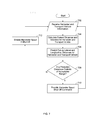
- FIG. 7 shows a flow chart of an embodiment of a control process for the control system of FIG. 4.
- FIGS. 1 and 2 show the relative positions of a harvester 10 and transport vehicle 20 during an unload on the go operation.
- the harvester 10 and the transport vehicle 20 can be controlled by a GPS based auto-guidance control system(s) in order to maintain a desired lateral distance (LAD) and a desired longitudinal distance (LOD) between the harvester 10 and the transport vehicle 20.
- the GPS based auto-guidance control system used in the exemplary embodiment can include a longitudinal distance control function which adjusts the speed of the transport vehicle 20 in following the harvester 10 to maintain a desired longitudinal distance (LOD).
- One exemplary embodiment of the reference points used for measuring the lateral distance and longitudinal distance is shown in FIG. 1. However, any suitable reference points for measuring lateral distance and longitudinal distance can be used.
- the desired lateral distance and desired longitudinal distance can both be preselected distances plus or minus a predetermined offset that ensures that crop material discharged from the harvester 10 is received and stored by the transport vehicle 20.
- the preselected lateral and longitudinal distances and the corresponding predetermined offsets can be related to the particular harvesters and transport vehicles being used, specifically the size of the storage area in the transport vehicle and an estimate of the shoot-out distance of the crop material from the harvester unload spout to the transport vehicle.
- the desired lateral distance and desired longitudinal distance are control targets.
- the actual lateral and longitudinal distances are measured and compared to the corresponding desired lateral and longitudinal distances for calculating distance errors, and the control system(s) control the vehicles towards zero errors.
- the desired lateral and longitudinal distances can gradually change around the normal lateral and longitudinal distances during unload on the go operation to provide a full or even filling of the loading receptacle of the transport vehicle. Otherwise, the desired lateral and longitudinal distances can be the same as the normal lateral and longitudinal distances.
- the harvester 10 can have a controller 12, a GPS device 14 and a wireless communication device 16.
- the transport vehicle 20 can have a controller 22, a GPS device 24 and a wireless communication device 26.
- the controller can be used to control operation of the harvester 10 and/or transport vehicle 20, regardless of which machine the controller may be installed on.
- the GPS device can be used to determine the position of the harvester 10 or the transport vehicle 20 and the wireless communication device can be used to send and receive information, data and control signals between the harvester 10 and the transport vehicle 20.
- the transport vehicle 20 can include a traction device 21 and a loading receptacle 23.
- a hitch angle sensor 25 can be used to determine the relative angle or hitch angle between the traction device 21 and the loading receptacle 23.
- the traction device 21 can be a tractor and the loading receptacle 23 can be a wagon.
- the traction vehicle 21 may be a truck or other self-propelled vehicle sufficient to transport loading receptacle 23 and the loading receptacle 23 may be a grain cart, bin, or other similar storage/transport vehicle.
- the transport vehicle 20 may be a truck, semi-trailer truck, tractor-trailer or other similar self-propelled container vehicle.
- the combine harvester 10 has an unloading tube or spout 18 transversely extending and fully deployed as it unloads crop material 100 through the discharge boot 30 and into the transport vehicle 20.
- the boot 30 can have any convenient and suitable shape.
- the boot 30 can be generally cylindrical, but can be more boxy with edges, or venturi-shaped, etc.
- the opening of the unloading tube or spout 18 at its distal end is peripherally sealed by a joint member 11 which hingedly engages portion 32 of the boot 30, which portion 32 interfaces the distal end of the unloading tube or spout 18.
- the joint member 11 can be rounded or spherical, but can also be cylindrical on a horizontal axis, so long as the interface between the tube or spout 18 and the boot 30 is adequately sealed. Angularly extending from portion 32 of the boot 30 is a spout end 31. Signals from the controller 12 of combine harvester 10, travel through conduits 47 for controlling the actuators 40, which actuators 40 can pivotally move the boot 30 up and down and back and forth in hinging relationship to the unloading tube or spout 18, via spherical joint 11. The joint 11 also serves to seal the interface at end 32 of the boot 30.
- the controllers 12, 22 can include a microprocessor, a non-volatile memory, an interface board, an analog to digital (A/D) converter, and a digital to analog (D/A) converter to control operation of the harvester 10, transport vehicle 20 and harvester spout control.
- the controllers 12, 22 can execute one or more control algorithms to control operation, guidance and/or steering of the harvester 10 and/or transport vehicle 20, to control the speed of the transport vehicle 20, and to implement harvester spout control.
- the control algorithm(s) can be computer programs or software stored in the non-volatile memory of the controllers 12, 22 and can include a series of instructions executable by the corresponding microprocessor of the controllers 12, 22.
- control algorithm be embodied in a computer program(s) and executed by the microprocessor, it is to be understood that the control algorithm may be implemented and executed using digital and/or analogue hardware by those skilled in the art. If hardware is used to execute the control algorithm, the corresponding configuration of the controllers 12, 22 can be changed to incorporate the necessary components and to remove any components that may no longer be required.
- controllers 12, 22 can be connected to or incorporate a user interface that permits an operator of the harvester 10 or transport vehicle 20 to interact with the controllers 12, 22. The operator can select and enter commands for the controllers 12, 22 through the user interface.
- the user interface can display messages and information from the controllers 12, 22 regarding the operational status of harvester 10 and/or transport vehicle 20.
- the user interfaces can be located locally to the controllers 12, 22, or alternatively, the user interfaces can be located remotely from the controllers 12, 22.
- FIGS. 3 and 6 show a control system and method for harvester spout orientation control during unload on the go operations.
- the control system and method can be implemented either on the harvester controller 12 or on the transport vehicle controller 22 because of the wireless communications between the harvester 10 and transport vehicle 20.
- a harvester GPS position, a transport vehicle GPS position and the hitch angle of the transport vehicle (if applicable) are provided (step 602) to a distance algorithm or controller in the corresponding controller 12 or 22.
- the distance algorithm or controller can then calculate a harvester velocity, a transport vehicle velocity, a current lateral distance between the harvester 10 and transport vehicle 20 and a current longitudinal distance between the harvester 10 and transport vehicle 20 (step 604).
- the corresponding controller then executes a distance deviation prediction algorithm or controller using the calculated harvester velocity, the transport vehicle velocity, the current lateral distance and the current longitudinal distance to predict future lateral and longitudinal distances and their distance deviations from the corresponding normal lateral distance and normal longitudinal distance (step 606) caused by sudden machine speed changes or other machine conditions or operations over a predetermined time period of prediction.
- the distance deviation prediction algorithm then compares the predicted lateral and longitudinal distances to the acceptable longitudinal distance range and the acceptable lateral distance range (step 608).
- the algorithm sends out the distance out of range signal together with the predicted distance deviations (step 610) to a harvester spout orientation control system or controller.
- the harvester spout orientation control system receives the distance out of range signal and the predicted distance deviations and controls the spout orientation accordingly to prevent a loss of crop material to the ground (step 612). Otherwise, the predicted longitudinal distance and lateral distance are within the acceptable distance ranges.
- the harvester spout orientation control system controls the spout to return to or stay at its normal orientation (step 614), that is, its zero adjustment orientation.
- the process begins again (step 602) at the next time step to determine if the harvester and transport vehicle are within acceptable ranges.
- FIG. 6 shows a flow chart of an embodiment of a control process for the case where the harvester spout orientation control system or controller is implemented by the harvester controller 12 which also implements the distance algorithm and the distance deviation prediction algorithm.
- the harvester spout orientation control system or controller can be implemented by an additional controller unit.
- the normal lateral distance and normal longitudinal distance are the lateral and longitudinal distances between the harvester and the transport vehicle when the two vehicles are aligned so that the loading receptacle 23 receives crop material at its centre area and the harvester spout is at its zero-adjustment configuration.
- the time period of prediction relates to the response time of the harvester spout control, and the value of the time period is dependent on how fast the harvester spout control system responds to a spout orientation control command signal or a spout shut-off command signal.
- the value of the time period of prediction is preset before an activation of unload on the go operation, and can be preset to, but not limited to, be slightly greater than the spout control response time. Before an unload on the go operation is activated, the value of the time period of prediction is set when an operator selects a harvester model on a user interface. The preset value is then sent from the user interface unit to the controller 12 and/or controller 22 before an unload on the go activation.
- the acceptable distance ranges relate to the dimensions of the harvester and its spout, dimensions of the transport vehicle and its storage area, and GPS antenna installation locations on the harvester and transport vehicle.
- the values of acceptable distance ranges are predetermined before an activation of unload on the go operation. Before an unload on the go operation is activated, the values of acceptable lateral distance range and acceptable longitudinal distance range are set when an operator selects a harvester model and a transport vehicle model with the dimensions of the storage area on the user interface. Those preset values are then sent from the user interface unit to the controller 12 and/or controller 22 before an unload on the go activation.
- the distance deviation prediction algorithm or controller receives information of harvester velocity and/or transport vehicle velocity from the corresponding harvester GPS device 14 and/or the transport vehicle GPS device 24, without using the harvester velocity and transport vehicle velocity calculated by the distance algorithm.
- the harvester spout control system can include the harvester spout orientation control system and one or more sensors to determine or measure the position of the spout, e.g., rotational position, and the position of the boot, e.g., fore and aft rotational position and/or lateral position. Using the known position of the spout and boot and the predicted distance deviations, the harvester spout control system can adjust the position or change the orientation of the spout and boot in response to receiving the distance out of range signal. The harvester spout control system can rotate the entire spout in either direction as shown by arrow A in FIG. 1.
- the harvester spout control system can also adjust the boot to redirect the crop material flow either rearward or forward, i.e., longitudinally, in the transport vehicle as shown by arrow B in FIG. 1.
- the harvester spout control system can further adjust the boot to redirect the crop material flow to be ejected either farther or closer, i.e., laterally, in the transport vehicle as shown by arrow C in FIG. 2.
- the particular adjustment to the spout and boot made by the harvester spout control system is dependent on the information received with the out of range signal. For example, if an unacceptable lateral distance deviation is to occur based on the out of range signal, the harvester spout control may adjust the lateral ejection distance of the spout and boot. In another example, if an unacceptable longitudinal distance deviation is to occur based on the out of range signal, the harvester spout control may adjust one or both of the rotational or longitudinal positions of the spout and boot depending on the amount of deviation.
- FIGS. 4 and 7 show a control system and method for emergency harvester spout shut off during unload on the go operations.
- the control system and method can be implemented either on the harvester controller 12 or on the transport vehicle controller 22 because of the wireless communications between the harvester 10 and transport vehicle 20.
- a harvester GPS position, a transport vehicle GPS position and a hitch angle of the transport vehicle (if applicable) are provided (step 702) to a distance algorithm or controller in the corresponding controller 12 or 22.
- the distance algorithm or controller can then calculate a harvester velocity, a transport vehicle velocity, a current lateral distance between the harvester 10 and transport vehicle 20 and a current longitudinal distance between the harvester 10 and transport vehicle 20 (step 704).
- the corresponding controller then executes a distance out of range prediction algorithm or controller using the harvester velocity, the transport vehicle velocity, the current lateral distance and the current longitudinal distance to predict future lateral and longitudinal distances and their deviations from corresponding normal lateral distance and normal longitudinal distance (step 706) caused by sudden machine speed changes or other machine conditions or operations over a harvester spout shut off response time.
- the distance out of range prediction algorithm then compares the predicted lateral and longitudinal distances to the acceptable longitudinal distance range and the acceptable lateral distance range (step 708).
- the algorithm sends out a harvester spout shut off command signal (step 710) to a harvester spout control system or the harvester control system.
- the harvester spout control system (not shown in FIG. 4) receives the shut off command and stops operation of the harvester spout until the longitudinal distance deviation and/or lateral distance deviation are within the acceptable distance ranges.
- the process begins again (step 702) at the next time step to determine if the harvester and transport vehicle are within acceptable ranges.
- the algorithm sends out a harvester spout enable or start command (step 712) to a harvester spout control system or the harvester control system to begin harvester spout operation if spout operation was stopped or to continue with harvester spout operation.
- FIG. 5 shows a control system for both emergency harvester spout shut off and harvester spout orientation control during unload on the go operations.
- the control system can be implemented either on the harvester controller 12 or on the transport vehicle controller 22 because of the wireless communications between the harvester 10 and transport vehicle 20.
- a harvester GPS position, a transport vehicle GPS position and the hitch angle of the transport vehicle (if applicable) are provided to a distance algorithm in the controller.
- the distance algorithm can then calculate a harvester velocity, a transport vehicle velocity, a current lateral distance between the harvester 10 and transport vehicle 20 and a current longitudinal distance between the harvester 10 and transport vehicle 20.
- a control algorithm uses the harvester velocity, the transport vehicle velocity, the current lateral distance and the current longitudinal distance from the distance algorithm to predict future lateral and longitudinal distances and their distance deviations from the normal lateral and longitudinal distances caused by sudden machine speed changes or other machine conditions or operations.
- the control algorithm then compares the predicted lateral and longitudinal distances to the acceptable longitudinal distance range and the acceptable lateral distance range.
- the algorithm predicts that the longitudinal distance and/or lateral distance between the harvester unload spout and the transport vehicle may go out of the acceptable distance ranges in the time period of prediction, the algorithm sends out the distance out of range signal together with the predicted distance deviations to a harvester spout control system.
- the harvester spout control system receives the distance out of range signal and the predicted distance deviations and controls spout orientation accordingly to prevent a loss of crop material to the ground.
- the algorithm sends out a harvester spout shut off command to a harvester spout control system or the harvester control system.
- the harvester spout control system receives the shut off command and stops operation of the harvester spout until the longitudinal distance and/or lateral distance are within the acceptable distance ranges.
- the particular control commands or signals provided by the control algorithm can be dependent on the magnitude of the deviation from the acceptable lateral and longitudinal distance ranges.
- the harvester spout control system can determine whether to adjust orientation of the spout or shut off the spout based on the control commands and signals provided by the control algorithm.
- the present application contemplates methods, systems and program products on any machine-readable media for accomplishing its operations.
- the embodiments of the present application may be implemented using existing computer processors, or by a special purpose computer processor for an appropriate system, or by a hardwired system.
- Embodiments within the scope of the present application include program products comprising machine-readable media for carrying or having machine-executable instructions or data structures stored thereon.
- Machine-readable media can be any available non-transitory media that can be accessed by a general purpose or special purpose computer or other machine with a processor.
- machine-readable media can include RAM, ROM, EPROM, EEPROM, CD-ROM or other optical disk storage, magnetic disk storage or other magnetic storage devices, or any other medium which can be used to carry or store desired program code in the form of machine-executable instructions or data structures and which can be accessed by a general purpose or special purpose computer or other machine with a processor.
- Machine-executable instructions comprise, for example, instructions and data which cause a general purpose computer, special purpose computer, or special purpose processing machines to perform a certain function or group of functions.
Landscapes
- Life Sciences & Earth Sciences (AREA)
- Environmental Sciences (AREA)
- Engineering & Computer Science (AREA)
- Mechanical Engineering (AREA)
- Guiding Agricultural Machines (AREA)
- Harvesting Machines For Root Crops (AREA)
Abstract
Description
Claims (15)
- A method of controlling operation of an unload spout of a moving harvester used to supply crop material to an associated transport vehicle, the method characterised by the steps of:predicting a lateral distance and a longitudinal distance between the harvester (20) and the transport vehicle (10) (step 606);determining if the predicted longitudinal distance is within a predetermined longitudinal distance range (step 608);determining if the predicted lateral distance is within a predetermined lateral distance range (step 608);transmitting a control signal to a harvester spout control system in response to at least one of the predicted longitudinal distance or the predicted lateral distance not being within the corresponding predetermined lateral and longitudinal distance ranges; andadjusting an operational configuration of the harvester spout from a first configuration in response to the transmission of the control signal to the harvester spout control system (step 612).
- The method of claim 1, further characterised by repeating predicting a lateral distance and a longitudinal distance, determining if the predicted longitudinal distance is within a predetermined longitudinal distance range and determining if the predicted lateral distance is within a predetermined lateral distance range after adjusting an operational configuration of the harvester spout.
- The method of claim 2, further characterised by returning the operational configuration of the harvester spout to the first configuration (step 614) in response to the predicted longitudinal distance and the predicted lateral distance being within corresponding predetermined lateral and longitudinal distance ranges (step 608).
- The method of claims 1 to 3, further characterised in that adjusting an operational configuration of the harvester spout (18) comprises stopping operation of the harvester spout (step 710).
- The method of claims 1 to 4, further characterised in that adjusting an operational configuration of the harvester spout (18) comprises adjusting an orientation of the harvester spout (step 612).
- The method of claim 5, further characterised in that adjusting an orientation of the harvester spout (step 612) comprises rotating the harvester spout (18).
- The method of claim 5 or 6, further characterised in that adjusting an orientation of the harvester spout (step 612) comprises adjusting one of a rotational position or a lateral position of a boot connected to the harvester spout (18).
- The method of any preceding claim, further characterised in that predicting a lateral distance and a longitudinal distance comprises:determining a velocity of a harvester;determining a velocity of an associated transport vehicle receiving crop material from the harvester;determining an actual longitudinal distance between the harvester and the transport vehicle;determining an actual lateral distance between the harvester and the transport vehicle;predicting a longitudinal distance deviation from a normal longitudinal distance; andpredicting a lateral distance deviation from a normal lateral distance.
- The method of any preceding claim, further characterised in that transmitting a control signal to a harvester spout control system comprises transmitting the predicted longitudinal distance deviation, the predicted lateral distance deviation and a distance out range signal to the harvester spout control system.
- The method of any preceding claim, further characterised in that adjusting an operational configuration of the harvester spout comprises measuring the position of the harvester spout (18) and adjusting an orientation of the harvester spout based on at least one of the measured position of the harvester spout, the distance out of range signal, the predicted longitudinal distance deviation or the predicted lateral distance deviation.
- A control system for a harvester spout comprising:a first global positioning system device (14) to determine a position of a harvester (10);a second global positioning system device (24) to determine a position of a transport vehicle (20);a first controller (12) comprising a microprocessor to execute a computer program to calculate a harvester velocity, a transport vehicle velocity, a lateral distance (LAD) between the harvester (10) and the transport vehicle (20) and a longitudinal distance (LOD) between the harvester (10) and the transport vehicle (20) in response to receiving the position of the harvester (10) from the first global positioning system device (14) and the position of the transport vehicle (20) from the second global positioning system device (24);a second controller (22) comprising a microprocessor to execute a computer program to predict future lateral and longitudinal distances between the harvester (10) and the transport vehicle (20) and determine whether the predicted lateral and longitudinal distances are within corresponding predetermined lateral and longitudinal distance ranges in response to receiving the harvester velocity, the transport vehicle velocity, the lateral distance (LAD) and the longitudinal distance (LOD) from the first controller (12); andthe second controller (22) transmits a control signal to adjust an operational configuration of the harvester spout (18) with the microprocessor executing the computer program in response to at least one of the predicted lateral and longitudinal distances being outside of the corresponding predetermined lateral and longitudinal distance ranges.
- The control system of claim 11, further characterised in that the second controller (22) transmits a second control signal to return the operational configuration of the harvester spout (18) to a prior operational configuration (step 614) in response to the predicted lateral and longitudinal distances being within the corresponding predetermined lateral and longitudinal distance ranges (step 608).
- The control system of claim 11 or 12, further characterised in that the transmitted control signal from the second controller (22) stops operation of the harvester spout (18) (step 710).
- The control system of claims 11 to 13, further characterised by a third controller comprising a microprocessor to execute a computer program to transmit a second control signal to adjust an orientation of the harvester spout (18) in response to receiving the control signal and the predicted lateral and longitudinal distance deviations from the second controller (22).
- The control system of claim 14 further characterised in that the transmitted second control signal from the third controller rotates the harvester spout (18).
Priority Applications (2)
| Application Number | Priority Date | Filing Date | Title |
|---|---|---|---|
| EP12704274.5A EP2675263B1 (en) | 2011-02-18 | 2012-02-15 | Harvester spout control system and method |
| BR112013021038-9A BR112013021038B1 (en) | 2011-02-18 | 2012-02-15 | CERTIFIER DISCHARGE NOZZLE CONTROL SYSTEM AND METHOD |
Applications Claiming Priority (4)
| Application Number | Priority Date | Filing Date | Title |
|---|---|---|---|
| US201161444454P | 2011-02-18 | 2011-02-18 | |
| US61/444,454 | 2011-02-18 | ||
| US13/171,645 US9002591B2 (en) | 2011-02-18 | 2011-06-29 | Harvester spout control system and method |
| US13/171,645 | 2011-06-29 |
Publications (1)
| Publication Number | Publication Date |
|---|---|
| WO2012110544A1 true WO2012110544A1 (en) | 2012-08-23 |
Family
ID=45607751
Family Applications (1)
| Application Number | Title | Priority Date | Filing Date |
|---|---|---|---|
| PCT/EP2012/052567 WO2012110544A1 (en) | 2011-02-18 | 2012-02-15 | Harvester spout control system and method |
Country Status (3)
| Country | Link |
|---|---|
| EP (1) | EP2675263B1 (en) |
| BR (1) | BR112013021038B1 (en) |
| WO (1) | WO2012110544A1 (en) |
Cited By (40)
| Publication number | Priority date | Publication date | Assignee | Title |
|---|---|---|---|---|
| WO2013096593A1 (en) * | 2011-12-20 | 2013-06-27 | Agco Corporation | Unloading auger control |
| EP2995191A1 (en) * | 2014-09-10 | 2016-03-16 | CLAAS Selbstfahrende Erntemaschinen GmbH | Method for controlling an overload process |
| EP3000307A1 (en) * | 2014-09-25 | 2016-03-30 | CLAAS Selbstfahrende Erntemaschinen GmbH | Method for overloading in crop harvesting machines |
| EP3062597B1 (en) | 2013-10-28 | 2020-02-26 | CNH Industrial Belgium nv | Unloading systems |
| US11079725B2 (en) | 2019-04-10 | 2021-08-03 | Deere & Company | Machine control using real-time model |
| US11178818B2 (en) | 2018-10-26 | 2021-11-23 | Deere & Company | Harvesting machine control system with fill level processing based on yield data |
| US11234366B2 (en) | 2019-04-10 | 2022-02-01 | Deere & Company | Image selection for machine control |
| US11240961B2 (en) | 2018-10-26 | 2022-02-08 | Deere & Company | Controlling a harvesting machine based on a geo-spatial representation indicating where the harvesting machine is likely to reach capacity |
| EP3949714A1 (en) | 2020-08-04 | 2022-02-09 | Deere & Company | Control arrangement and corresponding method for controlling the transfer of agricultural crop from a harvesting machine having a crop discharging device to a transport vehicle |
| US20220110251A1 (en) | 2020-10-09 | 2022-04-14 | Deere & Company | Crop moisture map generation and control system |
| EP4046474A1 (en) | 2021-02-18 | 2022-08-24 | Deere & Company | Harvester with feed forward control of filling mechanisms |
| US11467605B2 (en) | 2019-04-10 | 2022-10-11 | Deere & Company | Zonal machine control |
| US11474523B2 (en) | 2020-10-09 | 2022-10-18 | Deere & Company | Machine control using a predictive speed map |
| US11477940B2 (en) | 2020-03-26 | 2022-10-25 | Deere & Company | Mobile work machine control based on zone parameter modification |
| US11592822B2 (en) | 2020-10-09 | 2023-02-28 | Deere & Company | Machine control using a predictive map |
| US11589509B2 (en) | 2018-10-26 | 2023-02-28 | Deere & Company | Predictive machine characteristic map generation and control system |
| WO2023028474A1 (en) * | 2021-08-23 | 2023-03-02 | Silonz Llc | Semi-trailer carrying dump mule |
| US11635765B2 (en) | 2020-10-09 | 2023-04-25 | Deere & Company | Crop state map generation and control system |
| US11641800B2 (en) | 2020-02-06 | 2023-05-09 | Deere & Company | Agricultural harvesting machine with pre-emergence weed detection and mitigation system |
| US11650587B2 (en) | 2020-10-09 | 2023-05-16 | Deere & Company | Predictive power map generation and control system |
| US11653588B2 (en) | 2018-10-26 | 2023-05-23 | Deere & Company | Yield map generation and control system |
| US11675354B2 (en) | 2020-10-09 | 2023-06-13 | Deere & Company | Machine control using a predictive map |
| US11672203B2 (en) | 2018-10-26 | 2023-06-13 | Deere & Company | Predictive map generation and control |
| US11711995B2 (en) | 2020-10-09 | 2023-08-01 | Deere & Company | Machine control using a predictive map |
| US11727680B2 (en) | 2020-10-09 | 2023-08-15 | Deere & Company | Predictive map generation based on seeding characteristics and control |
| US11778945B2 (en) | 2019-04-10 | 2023-10-10 | Deere & Company | Machine control using real-time model |
| US11825768B2 (en) | 2020-10-09 | 2023-11-28 | Deere & Company | Machine control using a predictive map |
| US11845449B2 (en) | 2020-10-09 | 2023-12-19 | Deere & Company | Map generation and control system |
| US11844311B2 (en) | 2020-10-09 | 2023-12-19 | Deere & Company | Machine control using a predictive map |
| US11849672B2 (en) | 2020-10-09 | 2023-12-26 | Deere & Company | Machine control using a predictive map |
| US11849671B2 (en) | 2020-10-09 | 2023-12-26 | Deere & Company | Crop state map generation and control system |
| US11864483B2 (en) | 2020-10-09 | 2024-01-09 | Deere & Company | Predictive map generation and control system |
| US11874669B2 (en) | 2020-10-09 | 2024-01-16 | Deere & Company | Map generation and control system |
| US11889788B2 (en) | 2020-10-09 | 2024-02-06 | Deere & Company | Predictive biomass map generation and control |
| US11889787B2 (en) | 2020-10-09 | 2024-02-06 | Deere & Company | Predictive speed map generation and control system |
| US11895948B2 (en) | 2020-10-09 | 2024-02-13 | Deere & Company | Predictive map generation and control based on soil properties |
| US11927459B2 (en) | 2020-10-09 | 2024-03-12 | Deere & Company | Machine control using a predictive map |
| US11946747B2 (en) | 2020-10-09 | 2024-04-02 | Deere & Company | Crop constituent map generation and control system |
| US11957072B2 (en) | 2020-02-06 | 2024-04-16 | Deere & Company | Pre-emergence weed detection and mitigation system |
| US11983009B2 (en) | 2020-10-09 | 2024-05-14 | Deere & Company | Map generation and control system |
Citations (3)
| Publication number | Priority date | Publication date | Assignee | Title |
|---|---|---|---|---|
| EP1219153A2 (en) * | 2000-12-23 | 2002-07-03 | CLAAS Selbstfahrende Erntemaschinen GmbH | Device and method for coordinating and controlling agricultural vehicles |
| EP2020174A1 (en) * | 2007-08-03 | 2009-02-04 | AGROCOM GmbH & Co. Agrarsystem KG | Agricultural working machine |
| DE102008002006A1 (en) * | 2008-05-27 | 2009-12-03 | Deere & Company, Moline | Control arrangement for controlling the transfer of agricultural crop from a harvester to a transport vehicle |
-
2012
- 2012-02-15 BR BR112013021038-9A patent/BR112013021038B1/en active IP Right Grant
- 2012-02-15 EP EP12704274.5A patent/EP2675263B1/en active Active
- 2012-02-15 WO PCT/EP2012/052567 patent/WO2012110544A1/en active Application Filing
Patent Citations (3)
| Publication number | Priority date | Publication date | Assignee | Title |
|---|---|---|---|---|
| EP1219153A2 (en) * | 2000-12-23 | 2002-07-03 | CLAAS Selbstfahrende Erntemaschinen GmbH | Device and method for coordinating and controlling agricultural vehicles |
| EP2020174A1 (en) * | 2007-08-03 | 2009-02-04 | AGROCOM GmbH & Co. Agrarsystem KG | Agricultural working machine |
| DE102008002006A1 (en) * | 2008-05-27 | 2009-12-03 | Deere & Company, Moline | Control arrangement for controlling the transfer of agricultural crop from a harvester to a transport vehicle |
Cited By (44)
| Publication number | Priority date | Publication date | Assignee | Title |
|---|---|---|---|---|
| WO2013096593A1 (en) * | 2011-12-20 | 2013-06-27 | Agco Corporation | Unloading auger control |
| EP3062597B1 (en) | 2013-10-28 | 2020-02-26 | CNH Industrial Belgium nv | Unloading systems |
| EP2995191A1 (en) * | 2014-09-10 | 2016-03-16 | CLAAS Selbstfahrende Erntemaschinen GmbH | Method for controlling an overload process |
| EP2995191B1 (en) | 2014-09-10 | 2017-10-11 | CLAAS Selbstfahrende Erntemaschinen GmbH | Method for controlling an overload process |
| EP3000307A1 (en) * | 2014-09-25 | 2016-03-30 | CLAAS Selbstfahrende Erntemaschinen GmbH | Method for overloading in crop harvesting machines |
| US11653588B2 (en) | 2018-10-26 | 2023-05-23 | Deere & Company | Yield map generation and control system |
| US11178818B2 (en) | 2018-10-26 | 2021-11-23 | Deere & Company | Harvesting machine control system with fill level processing based on yield data |
| US11672203B2 (en) | 2018-10-26 | 2023-06-13 | Deere & Company | Predictive map generation and control |
| US11240961B2 (en) | 2018-10-26 | 2022-02-08 | Deere & Company | Controlling a harvesting machine based on a geo-spatial representation indicating where the harvesting machine is likely to reach capacity |
| US11589509B2 (en) | 2018-10-26 | 2023-02-28 | Deere & Company | Predictive machine characteristic map generation and control system |
| US11778945B2 (en) | 2019-04-10 | 2023-10-10 | Deere & Company | Machine control using real-time model |
| US11467605B2 (en) | 2019-04-10 | 2022-10-11 | Deere & Company | Zonal machine control |
| US11829112B2 (en) | 2019-04-10 | 2023-11-28 | Deere & Company | Machine control using real-time model |
| US11650553B2 (en) | 2019-04-10 | 2023-05-16 | Deere & Company | Machine control using real-time model |
| US11234366B2 (en) | 2019-04-10 | 2022-02-01 | Deere & Company | Image selection for machine control |
| US11079725B2 (en) | 2019-04-10 | 2021-08-03 | Deere & Company | Machine control using real-time model |
| US11957072B2 (en) | 2020-02-06 | 2024-04-16 | Deere & Company | Pre-emergence weed detection and mitigation system |
| US11641800B2 (en) | 2020-02-06 | 2023-05-09 | Deere & Company | Agricultural harvesting machine with pre-emergence weed detection and mitigation system |
| US11477940B2 (en) | 2020-03-26 | 2022-10-25 | Deere & Company | Mobile work machine control based on zone parameter modification |
| EP3949714A1 (en) | 2020-08-04 | 2022-02-09 | Deere & Company | Control arrangement and corresponding method for controlling the transfer of agricultural crop from a harvesting machine having a crop discharging device to a transport vehicle |
| US11849671B2 (en) | 2020-10-09 | 2023-12-26 | Deere & Company | Crop state map generation and control system |
| US11844311B2 (en) | 2020-10-09 | 2023-12-19 | Deere & Company | Machine control using a predictive map |
| US11635765B2 (en) | 2020-10-09 | 2023-04-25 | Deere & Company | Crop state map generation and control system |
| US11675354B2 (en) | 2020-10-09 | 2023-06-13 | Deere & Company | Machine control using a predictive map |
| US11983009B2 (en) | 2020-10-09 | 2024-05-14 | Deere & Company | Map generation and control system |
| US11711995B2 (en) | 2020-10-09 | 2023-08-01 | Deere & Company | Machine control using a predictive map |
| US11727680B2 (en) | 2020-10-09 | 2023-08-15 | Deere & Company | Predictive map generation based on seeding characteristics and control |
| US11592822B2 (en) | 2020-10-09 | 2023-02-28 | Deere & Company | Machine control using a predictive map |
| US11825768B2 (en) | 2020-10-09 | 2023-11-28 | Deere & Company | Machine control using a predictive map |
| US11474523B2 (en) | 2020-10-09 | 2022-10-18 | Deere & Company | Machine control using a predictive speed map |
| US11845449B2 (en) | 2020-10-09 | 2023-12-19 | Deere & Company | Map generation and control system |
| US11650587B2 (en) | 2020-10-09 | 2023-05-16 | Deere & Company | Predictive power map generation and control system |
| US11849672B2 (en) | 2020-10-09 | 2023-12-26 | Deere & Company | Machine control using a predictive map |
| US20220110251A1 (en) | 2020-10-09 | 2022-04-14 | Deere & Company | Crop moisture map generation and control system |
| US11864483B2 (en) | 2020-10-09 | 2024-01-09 | Deere & Company | Predictive map generation and control system |
| US11874669B2 (en) | 2020-10-09 | 2024-01-16 | Deere & Company | Map generation and control system |
| US11871697B2 (en) | 2020-10-09 | 2024-01-16 | Deere & Company | Crop moisture map generation and control system |
| US11889788B2 (en) | 2020-10-09 | 2024-02-06 | Deere & Company | Predictive biomass map generation and control |
| US11889787B2 (en) | 2020-10-09 | 2024-02-06 | Deere & Company | Predictive speed map generation and control system |
| US11895948B2 (en) | 2020-10-09 | 2024-02-13 | Deere & Company | Predictive map generation and control based on soil properties |
| US11927459B2 (en) | 2020-10-09 | 2024-03-12 | Deere & Company | Machine control using a predictive map |
| US11946747B2 (en) | 2020-10-09 | 2024-04-02 | Deere & Company | Crop constituent map generation and control system |
| EP4046474A1 (en) | 2021-02-18 | 2022-08-24 | Deere & Company | Harvester with feed forward control of filling mechanisms |
| WO2023028474A1 (en) * | 2021-08-23 | 2023-03-02 | Silonz Llc | Semi-trailer carrying dump mule |
Also Published As
| Publication number | Publication date |
|---|---|
| EP2675263A1 (en) | 2013-12-25 |
| BR112013021038A2 (en) | 2016-09-20 |
| EP2675263B1 (en) | 2015-04-15 |
| BR112013021038B1 (en) | 2018-06-26 |
Similar Documents
| Publication | Publication Date | Title |
|---|---|---|
| EP2675263B1 (en) | Harvester spout control system and method | |
| US9002591B2 (en) | Harvester spout control system and method | |
| AU2011359328B2 (en) | System and method for trajectory control of a transport vehicle used with a harvester | |
| US8606454B2 (en) | System and method for synchronized control of a harvester and transport vehicle | |
| US8180534B2 (en) | Multiple harvester unloading system | |
| US9326443B2 (en) | Arrangement and method for the automatic transfer of crops from a harvesting machine to a transport vehicle | |
| EP2579701B1 (en) | Automatic grain transfer control system based on real time modeling of a fill level for regions of the receiving container | |
| US9301447B2 (en) | Control arrangement for controlling the transfer of agricultural crop from a harvesting machine to a transport vehicle | |
| US9072227B2 (en) | System and method for improvement of harvest with crop storage in grain bags | |
| US6247510B1 (en) | Apparatus for the control of a transfer device | |
| US20120265412A1 (en) | Agricultural hauling vehicle and vehicle network | |
| US20100332051A1 (en) | Control Arrangement For Controlling The Transfer Of Agricultural Crop From A Harvesting Machine To A Transport Vehicle | |
| EP3111741B1 (en) | Unload spout inclination limit adjust system and method | |
| EP3815486B1 (en) | Automated fill strategy for grain cart using open-loop volumetric estimation of fill level | |
| US20240151188A1 (en) | Management of power transition for driver assistance | |
| US20230029905A1 (en) | Predictive power boost demand system for an agricultural vehicle |
Legal Events
| Date | Code | Title | Description |
|---|---|---|---|
| 121 | Ep: the epo has been informed by wipo that ep was designated in this application |
Ref document number: 12704274 Country of ref document: EP Kind code of ref document: A1 |
|
| WWE | Wipo information: entry into national phase |
Ref document number: 2012704274 Country of ref document: EP |
|
| NENP | Non-entry into the national phase |
Ref country code: DE |
|
| REG | Reference to national code |
Ref country code: BR Ref legal event code: B01A Ref document number: 112013021038 Country of ref document: BR |
|
| ENP | Entry into the national phase |
Ref document number: 112013021038 Country of ref document: BR Kind code of ref document: A2 Effective date: 20130816 |