WO2012066775A1 - Image capture device, image capture method - Google Patents
Image capture device, image capture method Download PDFInfo
- Publication number
- WO2012066775A1 WO2012066775A1 PCT/JP2011/006374 JP2011006374W WO2012066775A1 WO 2012066775 A1 WO2012066775 A1 WO 2012066775A1 JP 2011006374 W JP2011006374 W JP 2011006374W WO 2012066775 A1 WO2012066775 A1 WO 2012066775A1
- Authority
- WO
- WIPO (PCT)
- Prior art keywords
- resolution
- subject
- image
- shutter speed
- continuous
- Prior art date
Links
Images


Classifications
-
- G—PHYSICS
- G03—PHOTOGRAPHY; CINEMATOGRAPHY; ANALOGOUS TECHNIQUES USING WAVES OTHER THAN OPTICAL WAVES; ELECTROGRAPHY; HOLOGRAPHY
- G03B—APPARATUS OR ARRANGEMENTS FOR TAKING PHOTOGRAPHS OR FOR PROJECTING OR VIEWING THEM; APPARATUS OR ARRANGEMENTS EMPLOYING ANALOGOUS TECHNIQUES USING WAVES OTHER THAN OPTICAL WAVES; ACCESSORIES THEREFOR
- G03B7/00—Control of exposure by setting shutters, diaphragms or filters, separately or conjointly
- G03B7/08—Control effected solely on the basis of the response, to the intensity of the light received by the camera, of a built-in light-sensitive device
- G03B7/091—Digital circuits
- G03B7/093—Digital circuits for control of exposure time
-
- H—ELECTRICITY
- H04—ELECTRIC COMMUNICATION TECHNIQUE
- H04N—PICTORIAL COMMUNICATION, e.g. TELEVISION
- H04N23/00—Cameras or camera modules comprising electronic image sensors; Control thereof
- H04N23/60—Control of cameras or camera modules
- H04N23/68—Control of cameras or camera modules for stable pick-up of the scene, e.g. compensating for camera body vibrations
- H04N23/682—Vibration or motion blur correction
- H04N23/684—Vibration or motion blur correction performed by controlling the image sensor readout, e.g. by controlling the integration time
-
- H—ELECTRICITY
- H04—ELECTRIC COMMUNICATION TECHNIQUE
- H04N—PICTORIAL COMMUNICATION, e.g. TELEVISION
- H04N23/00—Cameras or camera modules comprising electronic image sensors; Control thereof
- H04N23/70—Circuitry for compensating brightness variation in the scene
- H04N23/73—Circuitry for compensating brightness variation in the scene by influencing the exposure time
-
- H—ELECTRICITY
- H04—ELECTRIC COMMUNICATION TECHNIQUE
- H04N—PICTORIAL COMMUNICATION, e.g. TELEVISION
- H04N23/00—Cameras or camera modules comprising electronic image sensors; Control thereof
- H04N23/80—Camera processing pipelines; Components thereof
-
- G—PHYSICS
- G03—PHOTOGRAPHY; CINEMATOGRAPHY; ANALOGOUS TECHNIQUES USING WAVES OTHER THAN OPTICAL WAVES; ELECTROGRAPHY; HOLOGRAPHY
- G03B—APPARATUS OR ARRANGEMENTS FOR TAKING PHOTOGRAPHS OR FOR PROJECTING OR VIEWING THEM; APPARATUS OR ARRANGEMENTS EMPLOYING ANALOGOUS TECHNIQUES USING WAVES OTHER THAN OPTICAL WAVES; ACCESSORIES THEREFOR
- G03B2207/00—Control of exposure by setting shutters, diaphragms, or filters separately or conjointly
- G03B2207/005—Control of exposure by setting shutters, diaphragms, or filters separately or conjointly involving control of motion blur
Definitions
- the present invention relates to a technique for photographing an object with high sensitivity and high resolution in the fields of digital still cameras, digital video cameras, network cameras, security cameras and the like.
- a continuous-shot composition that combines a plurality of images shot by continuous shooting into one image
- the technology of photographing is mounted on a conventional camera.
- the shutter speed is set to a sufficiently high speed that is not easily affected by camera shake, and the number of shots and sensitivity according to the subject brightness
- the shutter speed is set to a sufficiently high speed that is not easily affected by camera shake, and the number of shots and sensitivity according to the subject brightness
- the shutter speed is set shorter than the normal shutter speed.
- the exposure time for one continuous shot image is not the relatively long first time but the relatively short second time, and the exposure time is reduced.
- fixed pattern noise such as dark current noise is dominant in continuous shooting images when continuous shooting and combination shooting is performed.
- the illumination environment of the illumination to the subject in the image area may be a relatively dark environment.
- An object of the present invention is to provide an image pickup apparatus for continuously shooting a high-resolution image.
- an imaging device receives light from a subject and generates an image in which the subject is photographed, and the imaging unit continuously performs temporally A continuous-shot image combining unit that generates a continuous-shot composite image in which the subject is photographed by combining the two or more captured images; a luminance value of the subject; and a speed of the subject
- a parameter setting unit configured to set a shutter speed when capturing each of the two or more of the images.
- the parameter setting unit may set the shutter speed and the number of the images to be imaged according to the brightness value of the subject and the speed of the subject. That is, among the brightness value of the subject, the speed of the subject, the shutter speed, and the number of sheets, setting of the brightness value of the subject and the speed of the subject is performed by the parameter setting unit. I will not. On the other hand, the setting of the shutter speed and the number of sheets is performed by the parameter setting unit.
- a high-sensitivity, high-resolution image is obtained even when the speed of the subject is high and the amount of blur is large, or the illumination environment is very dark, or the luminance value of the subject is small. Can be taken.
- FIG. 1 is a diagram showing the structure of an imaging device in the first, second, and third embodiments of the present invention.
- FIG. 2 is a flowchart of the imaging device in the first, second, and third embodiments of the present invention.
- FIG. 3 is a diagram showing the structure of the imaging unit in the first, second, third, and fourth embodiments of the present invention.
- FIG. 4 is a diagram for explaining the relationship between the amount of shake depending on the shutter speed and the resolution.
- FIG. 5 is a diagram showing a table of blur amount and resolution stored in the velocity resolution database in the first, second, and third embodiments of the present invention.
- FIG. 6 is a diagram for explaining the relationship between the amount of noise and the resolution depending on the combination of the shutter speed and the number of continuous shots.
- FIG. 1 is a diagram showing the structure of an imaging device in the first, second, and third embodiments of the present invention.
- FIG. 2 is a flowchart of the imaging device in the first, second, and third embodiments of the present invention
- FIG. 7 is a diagram showing a table of noise amount and resolution stored in the luminance value resolution database in the first, second, and third embodiments of the present invention.
- FIG. 8 is a flowchart of the continuous shooting parameter calculation unit in the first embodiment of the present invention.
- FIG. 9 is a diagram showing graphs referred to in order to determine the shutter speed and the number of continuous shots in the continuous shooting parameter calculation unit in the first, second, and third embodiments of the present invention.
- FIG. 10 is a flowchart of the continuous shooting parameter calculation unit in the second embodiment of the present invention.
- FIG. 11 is a graph showing a shift amount and resolution table shift according to the object speed in the continuous shooting parameter calculation unit in the second embodiment of the present invention.
- FIG. 12 is a graph showing shift of the noise amount and resolution table according to a combination of subject brightness value and total exposure time in the continuous shooting parameter calculation unit in the second embodiment of the present invention .
- FIG. 13 is a diagram showing a graph to be referred to in order to determine the shutter speed and the number of continuous shots in the continuous shooting parameter calculation unit in the third embodiment of the present invention.
- FIG. 14 is a flowchart of the continuous shooting parameter calculation unit in the third embodiment of the present invention.
- FIG. 15 is a diagram showing the structure of the imaging device in the fourth embodiment of the present invention.
- FIG. 16 is a flowchart of the imaging device in Embodiment 4 of the present invention.
- FIG. 17 is a diagram showing an imaging device according to Embodiment 1 of the present invention.
- the imaging device 100 receives light 101L from a subject 101x and generates an image (for example, an image 92a) in which the subject 101x is photographed, and the imaging unit 100 generates an image by time.
- Continuously-shot image synthesis that generates a continuously-shot synthesized image (an image 93a generated from a plurality of images 92a) in which the subject 101x is photographed by combining two or more images that are continuously imaged.
- the luminance value of the subject 101x (the first luminance level indicated by the information 205a), and the speed of the subject 101x (the first movement indicated by the information 205v)
- a parameter setting unit 205 configured to set a shutter speed (exposure time) when each of the images is captured.
- the first resolution (broken line in FIG. 9), which is the upper limit of the resolution of the generated continuous-shot composite image, is determined from the second motion, which is the motion in which the first motion is performed.
- the second resolution upper limit of the resolution of the generated continuous-shot composite image
- the second luminance level which is a level obtained by multiplying the first luminance level by the length of the exposure time, etc.
- the setting is made in accordance with the above-described first resolution (dotted line) and the second resolution (solid line).
- the first resolution (dotted line) is equal to or higher than the threshold (for example, value X3 in FIG. 9)
- the second resolution (solid line) is A shutter speed lower than the threshold is set, and it is avoided that the resolution (image quality) of the generated continuous-shot composite image becomes low. That is, at the shutter speed (for example, the shutter speed L2), the shutter speed that is equal to or higher than the threshold value is set for the second resolution (solid line), and the resolution of the generated continuous-shot composite image can be increased.
- the setting is made in accordance with the above-described second movement specified from the speed (first movement) of the subject 101x and the exposure time.
- the exposure time suitable for the high speed is set not only for the normal speed but also for the relatively high speed, and the resolution (image quality) of the continuous-shot composite image generated is high. it can.
- the setting is made according to the above-mentioned second luminance level specified from the first luminance level and the exposure time.
- Embodiment 1 when performing continuous shooting and combined shooting for the purpose of camera shake correction as in Patent Document 1, it is possible to set an optimal shutter speed and the number of continuous shootings, which do not depend on the total exposure time.
- the camera itself is fixed (as in the case of security cameras, for example), and when the subject moves fast, it is necessary to obtain a higher resolution continuous-shot composite image for an image within a limited time .
- the image pickup apparatus is a combination of a shutter speed and the number of continuous shootings, which is optimal for continuous shooting and combined photographing in a total exposure time set by the user in order to obtain high sensitivity and high resolution continuous shooting combined images. Is determined using a set of the luminance value of the subject and the velocity of the subject.
- the total exposure time is the product of the shutter speed and the number of continuous shots.
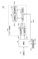
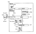
- FIG. 1 is a block diagram of an imaging device 100 according to Embodiment 1 of the present invention.
- FIG. 2 is a flowchart showing the entire processing of the imaging device 100.
- the imaging device 100 includes an imaging unit 101, a continuous shot image combining unit 107, and a parameter setting unit 108.
- the parameter setting unit 108 further includes a brightness value calculation unit 102, a speed calculation unit 103, a speed resolution database 104, a brightness value resolution database 105, and a continuous shooting parameter calculation unit 106.
- step S101 the luminance value calculation unit 102 calculates the luminance value (data 102d) of the subject (for example, the subject 101x in FIG. 1).
- step S102 the speed calculation unit 103 calculates the speed of the subject (data 103d).
- step S103 the continuous shooting parameter calculation unit 106 uses the luminance value and the speed of the subject calculated in the above-mentioned steps S101 and S102, and the total exposure time (described later) of the continuous shooting and combined shooting. The speed and the number of continuous shootings (the number of images to be captured by continuous shooting) are determined.
- the parameter setting unit 205 in FIG. 17 may be part of the parameter setting unit 108 in FIG. 1, for example.
- the parameter setting unit 205 may be, for example, a part of the parameter setting unit 108 that includes the continuous shooting parameter calculation unit 106 of FIG. 1 and does not include the luminance value calculation unit 102 and the speed calculation unit 103.
- step S103 it is determined by using data related to the camera such as the lens of the imaging unit 101, the aperture value, and the number of pixels of the imaging device.
- the accuracy of the parameters may be improved.
- step S104 the continuous shooting parameter calculation unit 106 sets the parameter determined in step S103 described above in the imaging unit 101.
- step S105 the imaging unit 101 captures a continuously shot image using parameters (shutter speed, number of continuously shot images, and the like) set for the imaging unit 101 in step S104 described above.
- step S106 the continuously shot image combining unit 107 creates a continuously shot composite image (image 107b) from the continuously shot images (plural images 107a) captured in step S105 described above.
- the imaging unit 101 outputs a plurality of continuously shot images using the camera parameters (shutter speed, number of continuously shot images, etc.) obtained by the continuous shooting parameter calculation unit 106. Also, data necessary for calculation of continuous shooting parameters, which is performed after this output, is output (see S101 and S102).
- FIG. 3 is a block diagram of the imaging unit 101.
- Imaging element unit 203 Light emitted from the subject 101 x passes through the lens 201 and the aperture 202, and is emitted to the imaging element unit (imaging unit) 203. In the imaging element unit 203, the light is converted into image data (data 203d) of a digital signal of the subject 101x.
- the processing such as the focal length, the aperture value, the sensitivity, the shutter speed, and the number of continuous shots according to the parameters set in the camera parameter setting unit 209. Change the set value in section 203A.
- the imaging device unit 203 outputs a plurality of temporally continuous image data to the continuous shot image combining unit 107 (FIG. 1). Further, since such image data is used by the luminance value calculation unit 102 (FIG. 1) to calculate the luminance value of the subject, the image data is also output to the luminance value calculation unit 102.
- the user setting unit 204 reads general camera parameters (data 204 d) set by the user, such as focal length, aperture value, sensitivity, and shutter speed. Then, the user setting unit 204 outputs the read camera parameter to the camera parameter setting unit 209.
- the user setting unit 204 sets the total exposure time of the continuous-shot composite image, the subject (for example, a face or a car), the subject area (for example, the entire image or a partial area of the image) set by the user. ), And the situation of the subject (for example, the speed, distance, illuminance, luminance value, etc. of the subject measured in advance). Then, the read setting is output to the luminance value calculation unit 102, the speed calculation unit 103, and the continuous shooting parameter calculation unit 106. Further, when the user sets the priority items in the calculation amount, the resolution, and the sensitivity in the continuous shooting and composite shooting, the items are output to the continuous shooting parameter calculation unit 106.
- the camera parameter setting unit 209 reflects general camera parameters such as focal length, aperture value, sensitivity, and shutter speed set in the user setting unit 204 on the lens 201, the aperture 202, and the image sensor unit 203.
- “reflect” means, for example, controlling the position of the lens 201 or the like.
- the above-described shutter speed and the number of continuously shot images obtained by the continuous shooting parameter calculation unit 106 are reflected in the imaging device unit 203. That is, for example, control is performed to capture each of the images of the number of images continuously shot at the shutter speed.
- the camera data holding unit 207 holds data.
- the data to be held may include, for example, the identification numbers of the lens 201, the aperture 202, and the imaging element unit 203 currently attached to the imaging device 100.
- the data may include a modulation transfer function (MTF) of the lens 201 according to the image height and the aperture value.
- the data may also include the number of pixels of the imaging device unit 203, temperature data of the imaging device unit 203 measured by the temperature sensor 206, and the like.
- the camera data holding unit 207 holds data of general camera parameters such as the focal length, the aperture value, the sensitivity, and the shutter speed which are currently set.
- the stored data are output to the luminance value calculation unit 102, the speed calculation unit 103, and the continuous shooting parameter calculation unit 106.
- the luminance value calculation unit 102 calculates the luminance value (data 102d, luminance value information 205a of FIG. 17) of the subject from the data (data 102d) output by the imaging unit 101, and the calculated luminance value Is output to the continuous shooting parameter calculation unit 106 (FIG. 1).
- the luminance value calculation unit 102 obtains a representative luminance value from the entire image data.
- a representative luminance value to be obtained for example, an average value of all image data, a minimum value, a maximum value or the like in image data can be used.
- the luminance value calculation unit 102 normalizes the calculated representative luminance value to a luminance value at an arbitrary shutter speed and sensitivity.
- the representative brightness value of the subject photographed with ISO400 which is the currently set shutter speed 1/8 (sec), which is the currently set shutter speed, with the shutter speed 1 (sec) and the sensitivity ISO100
- Such normalization is performed in order to make the luminance value used in the continuous shooting parameter calculation unit 106 not dependent on the camera parameter.
- a luminance value calculated based on data such as the illuminance of the subject and the luminance value, which has been measured in advance and set by the user setting unit 204 may be used.
- the user setting unit 204 may set the illuminance of the subject measured by the illuminance meter. Then, the luminance value calculation unit 102 can also obtain the luminance value of the subject as the luminance value associated with the set illuminance, using a table in which the illuminance and the luminance value are associated.
- the velocity calculator 103 calculates the velocity of the subject (data 103 d, relative velocity information 205 v of FIG. 17) from the data (data 103 d) output by the imaging unit 101, and calculates the calculated velocity It is output to the copying parameter calculation unit 106.
- the number of pixels (pixel / sec) in which the image of the subject moves can be used in one second.
- the speed of camera shake when the subject blurs due to camera shake is determined using the focal length (mm) output from the camera data holding unit 207. Treatment is done by doing things.
- the speed of the subject is determined from the difference between the position of the subject in the previous frame and the position of the subject in the current frame. It is possible to ask for
- a speed calculated based on previously measured data (data on the speed or distance of the subject, etc.) set in the user setting unit 204 may be used.
- the user when photographing a car as a subject, in the user setting unit 204, the user sets the speed of the car measured using a speed measuring instrument. Then, the distance obtained from the positional relationship between the road through which the car passes and the camera is set. From the speed of the car, the distance, and the focal length set in this way, it is possible to obtain the above-mentioned number of pixels in the image, which is the speed of the car in the image captured by the camera.
- the velocity resolution database 104 (FIG. 1) stores data (data 104d) indicating the relationship between the amount of blur and the resolution depending on the velocity of the subject.
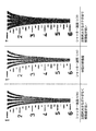
- FIG. 4 is a view showing an image of the eyelid portion of the resolution chart (ISO 12233) moving at the subject speed Y. As shown in FIG. That is, each of the three images of the image in the left column, the image in the center column, and the image in the right column shown in the table of FIG. 4 has a shutter different from the shutter speed of any other image. It is an image taken at speed.
- ISO 12233 the resolution chart
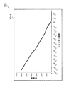
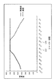
- FIG. 5 is a graph showing the relationship between the shutter speed and the resolution at the subject speed Y. As shown in FIG.
- the resolution on the vertical axis in FIG. 5 is a value (number) visually confirmed for the resolution from the resolution chart at each shutter speed (horizontal axis) taken as described in FIG. 4 described above.
- the resolution is not the resolution with values visually confirmed as such, but the resolution with a value measured with resolution measurement software or the like, or the contrast value with an arbitrary spatial frequency measured from a photographed image. Resolution etc. may be used.
- the velocity resolution database 104 (FIG. 1) is a table (hereinafter referred to as a velocity resolution table) showing the relationship between the amount of shake depending on the shutter speed (horizontal axis) and the resolution (vertical axis) as shown in FIG. As stored.
- a velocity resolution table showing the relationship between the amount of shake depending on the shutter speed (horizontal axis) and the resolution (vertical axis) as shown in FIG. As stored.
- the value of resolution corresponding to the velocity in the velocity resolution table differs depending on the velocity of the subject 101x.
- the resolution value also changes depending on the identification number of the lens 201, the MTF of the lens 201, the number of pixels of the image sensor unit 203, the aperture value, and the like according to the image height.
- the continuous shooting parameter calculation unit 106 can achieve higher accuracy. It is possible to refer to the table and avoid referencing other lower precision tables.
- position alignment of each continuous shot image in continuous shooting composite shooting (specifying the position in the other continuous shot image, etc. where the same place as the subject's location photographed in the position of one continuous shot image) It is also possible to take into account the deviation in the position (the positional relationship between those two positions). For example, it is possible to create a table with higher accuracy than the accuracy at the measured resolution itself by multiplying the measured resolution by a magnification factor that takes into account the resolution deterioration due to the above-mentioned deviation between each position. is there.
- the luminance value resolution database 105 (FIG. 1) stores data dependent on the combination of the total exposure time of continuous shooting and composite photography and the luminance value of the subject. For example, the data in the total exposure time and the luminance value in each set of two or more sets is stored. Each data is data (data 105d) indicating the relationship between the amount of noise (shutter speed) and the resolution.
- the amount of noise differs depending on the combination of shutter speed and the number of continuous shootings, even if the total exposure time of the continuous shooting and combining shooting is the same.
- FIG. 6 shows an image of a subject with a very small luminance value X, which is continuously photographed and combined with a total exposure time of 1/5 (sec).
- NR noise reduction
- a low pass filter When NR (noise reduction) such as a low pass filter is applied to the continuous-shot composite image in such a case, the amount of noise to be removed is large, so it is necessary to set the strength of NR strongly.
- the strong NR When the strong NR is applied, the resolution is greatly deteriorated simultaneously with the noise removal, so that the resolution which can be visually confirmed becomes low.
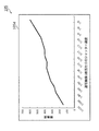
- FIG. 7 shows the shutter speed per one continuous shot image and the set of continuous shooting number (horizontal axis) in the set of the brightness value X and the total exposure time 1/5 (sec).
- the resolution (vertical axis) is a diagram showing the relationship.
- the number of continuous shots is uniquely determined by the shutter speed as the number of images obtained by dividing the “total exposure time” by the time of the “shutter speed”.
- the resolution in the luminance value resolution database 105 and the resolution in the velocity resolution database 104 use values measured on the same scale.
- the resolution may be measured without NR, or may be measured after existing NR is performed.
- the relationship with the resolution (noise amount, vertical axis) in the photographed and synthesized image is stored as a table (hereinafter, a luminance value resolution table).
- the resolution in the luminance value resolution table is determined depending on the combination of the total exposure time for continuous shooting and synthetic photography and the luminance value of the subject in the luminance value resolution table. Is different from the values in the luminance value resolution table in the other sets.
- the resolution value in the luminance value resolution table is the identification number of the imaging device unit 203, the number of pixels of the imaging device unit 203, and the temperature data of the imaging device unit 203 in the luminance value resolution table. Also change from the values in the other luminance value resolution tables. By preparing a luminance value resolution table corresponding to at least one of these, the continuous shooting parameter calculation unit 106 can refer to a table with higher accuracy.
- the data 103 d identifies a first movement (velocity) or the like that is a movement of the subject 101 x in a unit time.
- the first movement is a relative movement or the like with respect to the movement of the imaging device 100.
- a first resolution (broken line in FIG. 9), which is the upper limit of the resolution of the continuous-shot composite image generated when this second movement is performed, is specified.
- the first resolution is lower as the first movement mentioned above is relatively small and smaller as the second movement mentioned above, and higher as the first movement is relatively larger and the second movement is larger. .
- the data 103 d specifies the above-described first resolution (broken line in FIG. 9) as the resolution or the like in the above-described second movement in the above-described first movement indicated by the data 103 d.
- the data 102 d indicates a first luminance level or the like, which is the luminance level of the luminance of the subject 101 x, acquired during the unit time.
- a second luminance level which is the luminance level of the luminance of the subject 101x acquired during the exposure time, such as a level multiplied by the length of the exposure time.
- the second resolution (solid line in FIG. 9), which is the upper limit of the resolution of the generated continuous-shot composite image, is specified.
- the second resolution is lower as the fixed pattern noise ratio is higher, and higher as the fixed pattern noise ratio is lower.
- the pixels of the first luminance level described above may be buried in the fixed pattern noise of the high ratio level, and the second resolution may be low.
- the ratio is low, such second case may not be buried and the second resolution may be high.
- the above-mentioned second resolution (solid line in FIG. 9) is specified by the data 102 d as the resolution at the ratio of the above-mentioned second luminance level at the first luminance level indicated by the data 102 d. .
- the resolution of the continuous-shot composite image to be generated is, for example, a third resolution such as the lower one of the first resolution and the second resolution.
- the above-described first movement in the data 103d is, for example, a movement which is performed only for each exposure time (1/80 seconds, 1/40 seconds, 1/20 seconds, etc. in FIG. 9).
- the second movement at the exposure time is identified, which in turn determines the first resolution at each exposure time (values q1, q21, q22 etc. in FIG. 9).
- the data 102 d specifies the above-mentioned first resolution at each exposure time, and the above-mentioned second resolution at that exposure time specifies the second resolution at each exposure time.
- the resolution (values X2, X3, etc.) is specified.
- the above-described third resolution (values X2, X3, and X1 in FIG. 9) at each exposure time is specified by the two data of the data 103d and the data 102d.
- the data 103 d and the data 102 d identify the highest third resolution of the above-mentioned third resolutions at the plurality of exposure times, and the highest third resolution exposure time (FIG. 9). Then, 1/40 seconds) is identified.
- the first resolution (value X3) at the highest third resolution exposure time that is specified is the second resolution (value X3) at that exposure time Is the same as
- exposure is performed at the exposure time of the highest third exposure time described above, which is specified by the data 103 d and the data 102 d.
- the total time obtained by summing the exposure times of the continuous shot images is made the same as the total exposure time described above.
- control for example, it is controlled to capture each continuous shot image of the number of continuous shot images at the exposure of the exposure time.
- Such control is performed, for example, by outputting the information 205b (FIG. 17) indicating the above-mentioned exposure time and the information 205n indicating the above-mentioned number of sheets.
- This control is performed by, for example, the parameter setting unit 205 (FIG. 17).
- the continuous shooting parameter calculation unit 106 calculates the shutter speed and the number of continuous shootings that are optimal for continuous shooting combination shooting from the combination of the speed of the subject, the total exposure time of the continuous shooting combination shooting, and the brightness value of the subject. . Then, the calculated continuous shooting number and the like are output to the imaging unit 101.
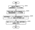
- a method for obtaining the shutter speed and the number of continuous shootings in the case where the total exposure time for continuous shooting and composite shooting is 1/5 (sec), the speed of the subject is Y, and the luminance value is X is shown in FIG. It demonstrates using a processing flow.
- FIG. 8 is a diagram showing a process flow.
- step S201 a velocity resolution table corresponding to the velocity Y of the subject as shown in FIG. 5 is referenced from the velocity resolution database 104.
- step S202 a luminance value corresponding to a combination of subject luminance value X and total exposure time 1/5 (sec), such as the luminance value resolution table in the graph shown in FIG. 7, in luminance value resolution database 105. Refer to the resolution table.
- step S203 using the velocity resolution table obtained in step S201 and step S202 and the luminance value resolution table, the shutter speed optimum for continuous shooting and composite shooting and the number of continuous shootings are calculated.
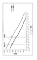
- FIG. 9 is a graph in which the resolution in FIG. 5 and the resolution in FIG. 7 are plotted.
- the resolutions on the vertical axis in FIG. 5 and FIG. 7 are measured on the same scale, so the velocity resolution table and the luminance value resolution table can be plotted on the same axis graph as in FIG. It is.
- the velocity resolution table represents the relationship between the amount of blurring (second movement described above) in the continuous-shot composite image and the resolution (broken line data) depending on the shutter speed (horizontal axis).
- the resolution (vertical axis) at the shutter time (horizontal axis) at a shorter time on the more left side is the higher resolution.
- the luminance value resolution table contains the shutter speed (horizontal axis) and the resolution (noise amount, solid line) of the continuous shooting composite image photographed under the combination of the shutter speed and the number of continuous shots (horizontal axis, shutter speed). Represents the relationship with data).
- the resolution (vertical axis) at the shutter speed (horizontal axis) at the shorter time on the more left side is the lower resolution.
- the resolution (of two resolutions) of the continuous shooting composite image at an arbitrary shutter speed (a combination of the shutter speed and the number of continuous shots, the horizontal axis of FIG. 9) Lower resolution) can be obtained.
- the shutter speed is set to 1/20 (sec) and the number of continuous shots is set to 4 will be described in detail first as parameters for continuous shooting and composite shooting (FIG. 4 right column, FIG. 6 right See the column).
- the resolution in the speed resolution table (broken line) and the resolution in the luminance value resolution table (solid line) are approximately the same (approximately the same) I understand that.
- the influence of resolution deterioration due to blurring and the influence of resolution deterioration due to noise become comparable.
- the resolution in the continuous shooting combined image is the highest value X3.
- the shutter speed (the combination of the shutter speed and the number of continuous shots) is set such that the degree of resolution deterioration due to blurring of the continuous-shot composite image and the degree of resolution deterioration due to noise of the continuous-shot composite image become equivalent.
- the shutter speed in continuous shooting and combining photography increases and the number of continuous shootings decreases.
- the number of continuous shots may be set to the lowest number.
- step S204 the combination of the shutter speed determined in step S203 and the number of continuously shot images is output to the camera parameter setting unit 209 (FIG. 3).
- the continuous shot image combining unit 107 (FIG. 1) combines a plurality of continuous shot images captured by the imaging unit 101.
- a method of specifying (positioning) a position where the same part in the subject is photographed in a plurality of continuously shot images can be considered. Then, in the method, the pixel value of the position in the continuously shot image specified in each continuously shot image is added up (added up) to the sum value. By doing this, appropriate operation can be realized.
- the same place in each continuously shot image as the place in the generated continuously shot composite image may be specified.
- the pixel value of the portion in the continuous shot combined image may be an average value obtained by averaging the pixel values of the specified portion in each continuous shot image.
- a method of alignment a method realized by the Lucas-Kanade method, a method realized by using information of a gyro sensor, or the like can be considered.
- blurring may remain, so after addition of the continuous shot images, existing blurs such as a Wiener filter or the like may be added to the above-described continuous shot composite image after addition.
- a correction can be made to further improve the resolution of the continuous-shot composite image.
- the point described in FIG. 17 is, for example, a point common to a plurality of embodiments which falls under the first embodiment and also applies to the other embodiments.
- the configuration in the second embodiment is, for example, basically the same as the configuration in the above-described first embodiment, but differs only in the processing in the continuous shooting parameter calculation unit 106.
- the continuous shooting parameter calculation unit 106 refers to the tables existing in the speed resolution database 104 and the luminance value resolution database 105 respectively.
- the speed resolution table has different values in the table depending on the subject speed
- the luminance value resolution table has different values in the table depending on the combination of the total exposure time of the continuous shooting combined photographing and the luminance value of the subject. For this reason, if the speed resolution table corresponding to each value of the subject speed is prepared, the amount of data to be used will be large.
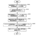
- FIG. 10 is a diagram showing a process flow in the second embodiment.
- the luminance value resolution database 105 there is no luminance value resolution table corresponding to the combination of the luminance value X and the total exposure time T, and the velocity resolution table corresponding to the combination of the luminance value 2X and the total exposure time T / 2 Assume that it exists.
- step S301 the velocity resolution table corresponding to the velocity Y / 2 of the object present in the velocity resolution database 104 is referred to.
- step S302 a velocity resolution table corresponding to the velocity Y is obtained from the velocity resolution table corresponding to the velocity Y / 2 to be referenced.
- the shake amount of the shutter speed 1/20 (sec) at the speed Y / 2 is the same as the shake amount of the shutter speed 1/40 (sec) at the speed Y. For this reason, the measured resolution is also the same.
- FIG. 11 is a diagram showing the relationship when the table is converted from the velocity resolution table of velocity Y / 2 to the velocity resolution table of velocity Y using this property.
- the data is shifted so that the resolution of the shutter speed S at the speed Y / 2 is the same as the resolution of the shutter speed S / 2 at the speed Y.
- step S303 the luminance value resolution table corresponding to the combination of the luminance value 2X of the subject and the total exposure time T / 2, which is present in the luminance value resolution database 105, is referred to.
- a luminance value resolution table corresponding to the combination of the luminance value X of the subject and the total exposure time T is a luminance value resolution table corresponding to the combination of the luminance value 2X of the subject and the total exposure time T / 2.
- a continuous-shot composite image in which a subject with a luminance value of 2X is photographed with a shutter speed of 1/80 (sec) and a total exposure time of 1/5 (sec) with 16 continuous shootings, and a subject with a luminance value of X
- a shutter speed of 1/40 (sec) and a continuous shot composite image shot with a total exposure time of 2/5 (sec) for 16 continuous shots the amount of exposure per continuous shot image, and continuous shooting The number will be the same. For this reason, the amount of noise and the resolution to be measured are the same.
- FIG. 12 is a table of luminance value resolution table of luminance value 2X and total exposure time T / 2
- FIG. 12 is a table of luminance value resolution table of luminance value X and total exposure time T.
- FIG. 6 is a diagram showing the relationship when the table is converted.
- the shutter speed S in the combination of the luminance value 2X and the total exposure time T / 2 is the shutter speed 2S in the combination of the luminance value X and the total exposure time T, continuous
- the shift is made to be the same as the resolution for T / 2S sheets.
- step S304 using the velocity resolution table and the luminance value resolution table obtained in step S302 and step S303, respectively, the shutter speed and the number of continuous shootings that are optimal for continuous shooting and composite shooting are calculated.
- the calculation method is the same as the method in step S203 of the first embodiment.
- step S305 the shutter speed determined in step S304 and the continuous shooting number are output to the camera parameter setting unit 209.
- the configuration in the third embodiment is basically the same as the configuration in the first embodiment, but only the processing of the continuous shooting parameter calculation unit 106 is different from the processing in the first embodiment.
- the resolutions of the velocity resolution table and the luminance value resolution table there are limit values depending on the number of pixels of the imaging device unit 203 and the MTF of the lens 201.
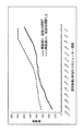
- FIG. 13 is a diagram showing a graph.
- the luminance value of the subject is a relatively bright value or when the speed of the subject is a relatively slow speed, as shown in FIG. 13, two of the speed resolution table and the luminance value resolution table
- the resolution in the table may be saturated to the limit value, and the shutter speed and the number of continuous shots may not be determined uniquely.
- FIG. 14 is a processing flow of processing of the continuous shooting parameter calculation unit 106 according to the third embodiment.
- steps S401 and S402 the velocity resolution table and the luminance value resolution table are obtained using the same method as the method in steps S201 and S202 of the first embodiment.
- step S403 it is determined whether the combination of the shutter speed and the continuous shooting number is uniquely determined in the speed resolution table and the luminance value resolution table obtained in step S401 and step S402.
- step S406 the shutter speed and the continuous shooting number are obtained by the same method as that in step S203 of the first embodiment.
- step S404 the shutter speed and the continuous shooting number are obtained according to the setting of the user.
- step S404 the shutter speed and the number of continuously shot images are obtained based on the priority items in the calculation amount, resolution, and sensitivity set by the user.
- the brightness value per one continuously shot image that is, the brightness value of the image of the subject in each continuously shot image increases. For this reason, the amount of noise of the continuous shooting combined image can be reduced.
- the resolution in the speed resolution table is the limit value, and the longer the shutter speed and the smaller the number of continuous shots, the better.
- the shutter speed of the continuously shot image per sheet is suitably 1/20 (sec).
- the speed of the subject may be faster than the speed calculated by the speed calculation unit 103, and the resolution may be higher as the shutter speed in continuous shooting composite shooting is shorter Sex is high.
- the resolution in the luminance value resolution table is the limit value, the shutter speed is short, and the number of continuous shots is large.
- 1/30 (sec) is suitable as a shutter speed for continuous shooting images per sheet, that is, a shutter speed at the time of capturing each continuous shooting image.
- step S405 the shutter speed and the continuous shooting number determined in step S404 or step S406 are output to the camera parameter setting unit 209.
- FIG. 15 is a block diagram of an imaging device in a fourth embodiment of the present invention.
- the shutter speed and the continuous shooting composite image obtained from the continuous shooting image synthesizing unit 107 are used without using the speed resolution database 104 and the luminance value resolution database 105 in the configuration diagram of FIG. Update the number of copies.
- the processing in each of the functional blocks of the imaging unit 101 and the continuous shot image combining unit 107 is the same processing as the processing in the functional block in the first embodiment.
- the processing of the continuous shooting parameter calculation unit 106 is different from the processing in the first embodiment.
- FIG. 16 is a processing flow of a method of updating the shutter speed and the continuous shooting number in the fourth embodiment.
- the total exposure time for continuous shooting and combined shooting is fixed.
- step S501 continuous shooting and combined shooting is performed with the shutter speed currently set in the imaging unit 101 and the number of continuous shooting.
- the continuously shot image combining unit 107 creates a continuously shot combined image.
- step S 502 the blur amount calculation unit 158 measures the blur amount in the continuous shot combined image obtained from the continuous shot image combining unit 107.
- the blur width of the subject in the continuous-shot composite image can be used as the blur amount to be measured.
- the blur width used is measured, for example, by using a general blind deconvolution method.
- the amount of blur depends on the speed of the subject, and the faster the speed of the subject, the larger the amount of blur.
- step S503 the noise amount calculation unit 159 measures the noise amount in the continuous shot combined image obtained from the continuous shot image combining unit 107.
- the noise amount may be determined from, for example, the variance value and the average value in the flat portion of the continuous-shot composite image.
- the dispersion value of light shot noise with respect to the value of the average value is obtained by calculation, and the measured dispersion value is divided by the dispersion value of light shot noise to obtain dark in continuous shooting composite image
- the ratio of current noise can be determined as the amount of noise.
- the dispersion value in an arbitrary rectangular area can be measured in the entire subject area, and the area with the smallest value can be obtained and used.
- Such noise amount depends on the luminance value of the subject, and the smaller the luminance value, the larger the noise amount.
- step S504 the continuous shooting parameter calculation unit 106 updates the shutter speed and the continuous shooting number using the shake amount and the noise amount obtained in step S502 and step S503.
- the shutter speed and the continuous shooting number are updated so as to lower the evaluation value calculated from the blur amount and the noise amount.
- the blur amount and the noise amount are multiplied by different weights respectively, and the value after multiplication by which the blur amount is multiplied and the value after multiplication by which the noise amount is multiplied are calculated.
- the calculation can be performed by finding the maximum value of two values.
- the weight for the blur amount is W1
- the weight for the noise amount is W2
- the product of the blur amount B and the weight W1 is W1 ⁇ B, and the product of the noise amount N and the weight W2 is W2 ⁇ N.
- W2 ⁇ N When W2 ⁇ N is adopted as the evaluation value, the shutter speed currently set is increased by one step and the continuous shooting number is shortened by one step in order to lower the evaluation value. Reduce according to things. As a result, the amount of noise in the continuous shooting combined image can be reduced, and the value of W2 ⁇ N can be lowered.
- a value set by the user is used by the user setting unit 204 as each value of the weights W1 and W2 applied to the shake amount and the noise amount.
- a method of calculating the weight a method of calculating by using a continuous-shot composite image captured in advance can be applied.
- step S505 the shutter speed determined in step S504 and the number of continuously shot images are output to the camera parameter setting unit 209.
- the shutter speed (FIG. 9) in which the influence of the resolution deterioration due to blurring and the resolution deterioration due to noise become comparable
- a combination of the shutter speed at the point where the solid line and the broken line intersect and the number of continuous shootings is set, and a high resolution and high sensitivity continuous shooting composite image can be obtained.
- the optimal shutter speed and the number of continuous shootings are updated accordingly, so it is suitable for performing continuous shooting composite shooting continuously ing.
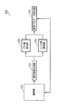
- FIG. 17 is a diagram showing the imaging device 100. As shown in FIG. 17
- the imaging apparatus 100 includes a parameter setting unit 205, an imaging unit 203, and a continuous shot image combining unit 107.
- the parameter setting unit 205 receives information (luminance value information) 205a indicating a luminance value and information (relative velocity information) 205v related to the relative velocity of the subject.
- the parameter setting unit 205 outputs information 205 b indicating the shutter speed specified from the input information 205 a and the information 205 v.
- the parameter setting unit 205 also outputs information 205 n indicating the number of continuous shots corresponding to the shutter speed.
- the imaging unit 203 captures each of continuously shot images of the number of continuously shot images indicated by the output information 205 n at a shutter speed indicated by the output information 205 b.
- Each continuous shot image to be captured is an image in which the subject 101x is captured.
- the continuous shot image synthesis unit 107 generates an image (continuous shooting composite image) 93a in which the subject 101x is shot from the captured continuous shot images of the number of images.
- the following operation may be performed, for example, at a certain stage.
- the subject 101x is imaged in the imaging operation 203x, and the first image 93a including the image 93m of the subject 101x is generated.
- the image 93m included in the first image 93a to be generated may have blur.
- the second image 92a including the image 92m of the subject 101x is captured in the second time exposure. That is, an image including the image of the subject 101x is not captured in the first time exposure that is longer than the second time.
- the blur (blur 92p) of the image 92m of the subject 101x in the second image 92a is smaller than the blur of the image of the subject 101x in the image during the first time exposure.
- the first time is, for example, a time obtained by totaling the second time for the plurality of captured second images 92a.
- a plurality of such second images 92a are captured. That is, the plurality of second images 92a are a plurality of images in which the subject 101x is captured in continuous shooting.
- a first image 93a is generated from the plurality of captured second images 92a. Since blurring of each continuous shot image (second image 92a) becomes small, blurring of the combined image (first image 93a) is also small. That is, the blur in the first image 93a is smaller than the blur in the image captured by the exposure for the first time.
- an appropriate continuous-shot image can be acquired, and a first generated from the plurality of second images 92a. It is conceivable that the image quality (for example, resolution) of the image 93a is high.
- the image quality of the first image 93a generated from the second image 92a is not high.
- the image quality of the first image 93a generated from the plurality of second images 92a also increases.
- the image quality of the first image 93a is It gets lower.
- brightness value information 205a (see data 102d in FIG. 1 and S101 in FIG. 2) indicating whether the subject 101x is illuminated by the strong light 91a or not illuminated by the strong light 91a may be acquired.
- the acquired luminance value information 205a may indicate, for example, whether or not the luminance value of the image 92m in each of the second images 92a is higher than a threshold. In the case of indicating high, it may indicate that it is illuminated by strong light 91a, and in the case of not indicating high it may indicate that it is not illuminated by strong light 91a.
- the first image 93a is generated from the plurality of second images 92a to be captured only when illuminated by the strong light 91a.
- the first image 93a may be generated from the plurality of third images 92b when it is indicated that the strong light 91a is not illuminated.
- the third image 92b is a third time (shutter speed L2) longer than the above-described second time (for example, the time at the shutter speed L1 in FIG. 9) including the image 92n of the subject 101x. Image taken with the exposure in
- the image quality of the image generated from the plurality of third images 92b (see the resolution of value X3 in FIG. 9, the relatively high resolution of the image in the center column in FIG. 6, etc.) is dark as described above. Also in the second case, it is relatively high (see the value X2 of the resolution at the shutter speed L1, lower than the value X3, the relatively low resolution of the image in the left column of FIG. 6, etc.).
- the first image 93a is generated using the second image 92a in the bright first case, and the first image 93a is generated using the third image 92b in the second case where it is not bright. Generate Thereby, in any case, an appropriate generated image can be acquired.
- the exposure time (shutter speed) at the time of capturing the third image 92b is the optimal exposure time specified from the luminance value information 205a and the relative speed information 205v of the subject described above. It is. Therefore, sufficient resolution can be obtained even in the generated image.
- the above-described imaging device is specifically a computer system including a microprocessor, a ROM, a RAM, a hard disk unit, a display unit, a keyboard, a mouse and the like.
- a computer program is stored in the RAM or the hard disk unit.
- the imaging device achieves its functions by the microprocessor operating according to the computer program.
- the computer program is configured by combining a plurality of instruction codes indicating instructions to the computer in order to achieve a predetermined function.
- the system LSI is a super-multifunctional LSI manufactured by integrating a plurality of components on one chip, and more specifically, a computer system including a microprocessor, a ROM, a RAM, and the like. . A computer program is stored in the RAM. The system LSI achieves its functions as the microprocessor operates in accordance with the computer program.
- Some or all of the components constituting the imaging device described above may be configured from an IC card or a single module that is removable from the imaging device.
- the IC card or the module is a computer system including a microprocessor, a ROM, a RAM, and the like.
- the IC card or the module may include the super multifunctional LSI described above.
- the IC card or the module achieves its function by the microprocessor operating according to the computer program. This IC card or this module may be tamper resistant.
- the present invention may be the method shown above. Further, the present invention may be a computer program that realizes these methods by a computer, or may be a digital signal composed of the computer program.
- the present invention is a computer readable recording medium that can read the computer program or the digital signal, such as a flexible disk, a hard disk, a CD-ROM, an MO, a DVD, a DVD-ROM, a DVD-RAM, a BD (Blu-ray Disc ), And may be recorded in a semiconductor memory or the like. Further, the present invention may be the digital signal recorded on these recording media.
- the computer program or the digital signal may be transmitted via a telecommunication line, a wireless or wired communication line, a network represented by the Internet, data broadcasting, and the like.
- the present invention may be a computer system comprising a microprocessor and a memory, wherein the memory stores the computer program, and the microprocessor operates according to the computer program.
- the present invention can be managerially, continuously and repeatedly used in the industry that manufactures and sells imaging devices or information processing devices that perform image processing.
- the imaging device of the present invention in a security camera such as a security camera or a surveillance camera, even in a scene where a person or a car passes through in an instant, high resolution images can be obtained.
- a security camera such as a security camera or a surveillance camera
- high resolution images can be obtained.
- general consumers such as digital still cameras and digital video cameras.
Landscapes
- Engineering & Computer Science (AREA)
- Multimedia (AREA)
- Signal Processing (AREA)
- Physics & Mathematics (AREA)
- General Physics & Mathematics (AREA)
- Studio Devices (AREA)
- Exposure Control For Cameras (AREA)
- Image Processing (AREA)
Abstract
Description
一般に、特許文献1のように、手ブレ補正を目的に、連写合成撮影を行う場合、総露光時間に依存しない、最適なシャッター速度と、連写枚数とを設定できる。
Generally, when performing continuous shooting and combined shooting for the purpose of camera shake correction as in
次に、実施の形態2について、説明する。本実施の形態2での構成は、例えば、基本的に、上述の実施の形態1での構成と同じ構成であるが、連写パラメータ算出部106での処理のみが異なる。 Second Embodiment
Next, the second embodiment will be described. The configuration in the second embodiment is, for example, basically the same as the configuration in the above-described first embodiment, but differs only in the processing in the continuous shooting
次に、実施の形態3について説明する。本実施の形態3での構成は、実施の形態1での構成と、基本的に同じ構成であるが、連写パラメータ算出部106の処理のみが、実施の形態1での処理とは異なる。 Third Embodiment
Next, the third embodiment will be described. The configuration in the third embodiment is basically the same as the configuration in the first embodiment, but only the processing of the continuous shooting
次に、実施の形態4について説明する。 Embodiment 4
Next, the fourth embodiment will be described.
なお、本発明を上記実施の形態に基づいて説明してきたが、本発明は、上記の実施の形態に限定されないのはもちろんである。以下のような場合も本発明に含まれる。 (Other modifications)
Although the present invention has been described based on the above embodiment, it is needless to say that the present invention is not limited to the above embodiment. The following cases are also included in the present invention.
102 輝度値算出部
103 速度算出部
104 速度解像度データベース
105 輝度値解像度データベース
106 連写パラメータ算出部
107 連写画像合成部
108 パラメータ設定部
158 ブレ量算出部
159 ノイズ量算出部
201 レンズ
202 絞り
203 撮像素子部
204 ユーザー設定部
206 温度センサ
207 カメラデータ保持部
209 カメラパラメータ設定部 101
Claims (13)
- 被写体からの光を受光して、前記被写体が写された画像を生成する撮像部と、
前記撮像部によって、時間的に連続して撮像された、2以上の枚数の前記画像を合成することにより、前記被写体が写された連写合成画像を生成する連写画像合成部と、
前記被写体の輝度値と前記被写体の速度とに応じて、2以上の前記枚数の前記画像のうちのそれぞれの前記画像が撮像される際におけるシャッター速度を設定するパラメータ設定部と、
を備える撮像装置。 An imaging unit that receives light from a subject and generates an image in which the subject is photographed;
A continuous-shot image synthesis unit that generates a continuous-shot composite image in which the subject is photographed by combining two or more of the images captured continuously in time by the imaging unit;
A parameter setting unit configured to set a shutter speed at which each of the plurality of images is captured according to the brightness value of the subject and the speed of the subject;
An imaging device comprising: - 前記パラメータ設定部は、前記被写体の前記輝度値と前記被写体の前記速度とに応じて、前記シャッター速度と撮像がされる前記画像の前記枚数とを設定する
を備える請求項1に記載の撮像装置。 The imaging device according to claim 1, wherein the parameter setting unit sets the shutter speed and the number of the images to be imaged according to the brightness value of the subject and the speed of the subject. . - 前記パラメータ設定部は、前記被写体の、当該撮像装置に対する相対的な速度が速いほど、前記シャッター速度として、より短い時間のシャッター速度を設定し、かつ、前記枚数として、より多い枚数を設定する
請求項2に記載の撮像装置。 The parameter setting unit sets a shutter speed for a shorter time as the shutter speed as the relative speed of the subject with respect to the imaging apparatus is higher, and sets a larger number as the number. An imaging device according to Item 2. - 前記パラメータ設定部は、前記被写体の前記輝度値が小さいほど、前記シャッター速度として、より長い時間のシャッター速度を設定し、かつ、前記枚数として、より少ない枚数を設定する
請求項2に記載の撮像装置。 The imaging according to claim 2, wherein the parameter setting unit sets a shutter speed for a longer time as the shutter speed as the brightness value of the subject is smaller, and sets a smaller number as the number. apparatus. - 前記撮像部は、それぞれの前記画像が撮像されるよりも前に、総露光時間を設定可能であるユーザー設定部を備え、
設定される前記枚数は、その枚数と、設定される前記シャッター速度との積が、前記ユーザー設定部で設定された前記総露光時間と一致する枚数である
請求項2から4の何れか1項に記載の撮像装置。 The imaging unit includes a user setting unit capable of setting a total exposure time before each of the images is imaged;
The number of sheets set is the number of sheets in which the product of the number of sheets and the shutter speed set is the same as the total exposure time set by the user setting unit. The imaging device according to. - 前記パラメータ設定部は、前記連写合成画像においての、ブレによる、解像度劣化の程度と、前記連写合成画像においての、ノイズによる、解像度劣化の程度とが同程度になるように、前記シャッター速度と前記枚数とを設定する
請求項2に記載の撮像装置。 The parameter setting unit sets the shutter speed such that the degree of resolution deterioration due to blurring in the continuous-shot composite image and the degree of resolution deterioration due to noise in the continuous-shot composite image become equivalent to each other. The image pickup apparatus according to claim 2, wherein the number and the number are set. - 前記被写体の前記速度に依存した、前記ブレのブレ量と、前記ブレによる、前記解像度劣化の程度との関係を示す速度解像度データベースと、
前記被写体の前記輝度値に依存した、前記ノイズのノイズ量と、前記ノイズによる、前記解像度劣化の程度との関係を示す輝度値解像度データベースとを備える
請求項6に記載の撮像装置。 A velocity resolution database indicating a relationship between a blur amount of the blur and a degree of the resolution deterioration due to the blur depending on the velocity of the subject;
The imaging device according to claim 6, further comprising: a luminance value resolution database indicating a relationship between a noise amount of the noise and a degree of the resolution deterioration due to the noise depending on the luminance value of the subject. - 前記パラメータ設定部は、
前記速度解像度データベースに存在する、前記被写体の第1の前記速度に依存した第1のブレ量での前記ブレによる、前記解像度劣化の程度を示す第1のデータから、
前記速度解像度データベースに存在しない、前記被写体の第2の前記速度に依存した第2のブレ量での前記ブレによる前記解像度劣化の程度を示す第2のデータを生成する
請求項6に記載の撮像装置。 The parameter setting unit
From the first data indicating the degree of the resolution deterioration due to the blurring with the first blurring amount dependent on the first speed of the subject, which is present in the velocity resolution database,
7. The imaging according to claim 6, wherein second data indicating a degree of the resolution deterioration due to the shake at a second shake amount dependent on the second speed of the subject that is not present in the speed resolution database is generated. apparatus. - 前記パラメータ設定部は、
前記輝度値解像度データベースに存在する、前記被写体の第1の前記輝度値に依存した第1のノイズ量の前記ノイズによる、前記解像度劣化の程度を示す第1のデータから、
前記輝度値解像度データベースに存在しない、前記被写体の第2の前記輝度値に依存した第2のノイズ量の前記ノイズによる、前記解像度劣化の程度を示す第2のデータを生成する
請求項7または8に記載の撮像装置。 The parameter setting unit
From the first data indicating the degree of the resolution deterioration due to the noise of the first noise amount depending on the first luminance value of the subject, which is present in the luminance value resolution database
The second data indicating the degree of the resolution deterioration due to the noise of the second noise amount depending on the second luminance value of the subject not present in the luminance value resolution database is generated. The imaging device according to. - 前記速度解像度データベースは、速度解像度テーブルを格納し、
格納される前記速度解像度テーブルは、前記被写体のそれぞれの前記速度における、シャッター速度と解像度との間の、測定された関係を示し、
前記輝度値解像度データベースは、輝度値解像度テーブルを格納し、
格納される前記輝度値解像度テーブルは、前記被写体のそれぞれの前記輝度値における、シャッター速度と解像度との間の、測定された関係を示す
請求項7から9の何れか1項に記載の撮像装置。 The velocity resolution database stores velocity resolution tables,
The stored speed resolution table indicates the measured relationship between shutter speed and resolution at each of the speeds of the subject;
The luminance value resolution database stores a luminance value resolution table,
The imaging device according to any one of claims 7 to 9, wherein the luminance value resolution table stored indicates a measured relationship between shutter speed and resolution at each of the luminance values of the subject. . - 設定される前記シャッター速度は、当該シャッター速度に対して、前記速度解像度テーブルにおける前記関係が対応付ける前記解像度と、当該シャッター速度に対して、前記輝度値解像度テーブルにおける前記関係が対応付ける前記解像度とが一致するシャッター速度である
請求項7から10の何れか1項に記載の撮像装置。 The shutter speed to be set corresponds to the resolution that the relationship in the speed resolution table corresponds to the shutter speed, and the resolution that the relationship in the luminance value resolution table corresponds to the shutter speed. The imaging device according to any one of claims 7 to 10, wherein - 前記シャッター速度は、撮像条件に基づいて設定され、
前記撮像条件は、レンズの識別番号、撮像素子の識別番号、絞り値、温度のうちの少なくとも1つを含む
請求項5に記載の撮像装置。 The shutter speed is set based on imaging conditions,
The imaging device according to claim 5, wherein the imaging condition includes at least one of an identification number of a lens, an identification number of an imaging element, an aperture value, and a temperature. - 被写体からの光を受光して、前記被写体が写された画像を生成する撮像ステップと、
前記撮像ステップで、時間的に連続して撮像された、2以上の枚数の前記画像を合成することにより、前記被写体が写された連写合成画像を生成する連写画像合成ステップと、
前記被写体の輝度値と前記被写体の速度とに応じて、2以上の前記枚数の前記画像のうちのそれぞれの前記画像が撮像される際におけるシャッター速度を設定するパラメータ設定ステップと、
を含む撮像方法。 An imaging step of receiving light from a subject to generate an image in which the subject is photographed;
A continuous-shot image synthesis step of generating a continuous-shot composite image in which the subject is photographed by combining two or more of the images captured continuously in time in the imaging step;
A parameter setting step of setting a shutter speed when each of the plurality of images is captured according to the brightness value of the subject and the speed of the subject;
An imaging method including:
Priority Applications (4)
| Application Number | Priority Date | Filing Date | Title |
|---|---|---|---|
| EP11842443.1A EP2642746B1 (en) | 2010-11-18 | 2011-11-16 | Image capture device, image capture method |
| JP2012519263A JP5940974B2 (en) | 2010-11-18 | 2011-11-16 | Imaging apparatus and imaging method |
| CN201180006263.8A CN102714699B (en) | 2010-11-18 | 2011-11-16 | Camera head, image capture method |
| US13/522,342 US8896728B2 (en) | 2010-11-18 | 2011-11-16 | Image capturing device and image capturing method including setting shutter speed based on blur and noise |
Applications Claiming Priority (2)
| Application Number | Priority Date | Filing Date | Title |
|---|---|---|---|
| JP2010-257593 | 2010-11-18 | ||
| JP2010257593 | 2010-11-18 |
Publications (1)
| Publication Number | Publication Date |
|---|---|
| WO2012066775A1 true WO2012066775A1 (en) | 2012-05-24 |
Family
ID=46083723
Family Applications (1)
| Application Number | Title | Priority Date | Filing Date |
|---|---|---|---|
| PCT/JP2011/006374 WO2012066775A1 (en) | 2010-11-18 | 2011-11-16 | Image capture device, image capture method |
Country Status (5)
| Country | Link |
|---|---|
| US (1) | US8896728B2 (en) |
| EP (1) | EP2642746B1 (en) |
| JP (1) | JP5940974B2 (en) |
| CN (1) | CN102714699B (en) |
| WO (1) | WO2012066775A1 (en) |
Cited By (4)
| Publication number | Priority date | Publication date | Assignee | Title |
|---|---|---|---|---|
| KR20140027816A (en) * | 2012-08-27 | 2014-03-07 | 삼성전자주식회사 | Photographing apparatus, method for controlling the same, and computer-readable recording medium |
| JP2014063656A (en) * | 2012-09-21 | 2014-04-10 | Asahi Kasei Homes Co | Lighting control system |
| WO2016075969A1 (en) * | 2014-11-10 | 2016-05-19 | ソニー株式会社 | Signal processing device and image capturing system |
| CN107077720A (en) * | 2016-12-27 | 2017-08-18 | 深圳市大疆创新科技有限公司 | Method, device and the equipment of image procossing |
Families Citing this family (22)
| Publication number | Priority date | Publication date | Assignee | Title |
|---|---|---|---|---|
| KR101889932B1 (en) * | 2012-07-25 | 2018-09-28 | 삼성전자주식회사 | Apparatus and Method for photographing image |
| JP6048911B2 (en) * | 2012-12-17 | 2016-12-21 | 株式会社リコー | Image processing apparatus, image processing method, and imaging apparatus |
| US9591211B2 (en) | 2013-05-10 | 2017-03-07 | Huawei Technologies Co., Ltd. | Photographing method and apparatus |
| CN104144289B (en) * | 2013-05-10 | 2018-02-06 | 华为技术有限公司 | Photographic method and device |
| US9615012B2 (en) * | 2013-09-30 | 2017-04-04 | Google Inc. | Using a second camera to adjust settings of first camera |
| US9565416B1 (en) | 2013-09-30 | 2017-02-07 | Google Inc. | Depth-assisted focus in multi-camera systems |
| US9478010B2 (en) * | 2013-12-12 | 2016-10-25 | Google Technology Holdings LLC | Generating an enhanced image of a predetermined scene from a plurality of images of the predetermined |
| CN103888683B (en) | 2014-03-24 | 2015-05-27 | 深圳市中兴移动通信有限公司 | Mobile terminal and shooting method thereof |
| KR20160016068A (en) * | 2014-08-01 | 2016-02-15 | 삼성전자주식회사 | Method for generating image and electronic device thereof |
| CN105472231B (en) * | 2014-09-03 | 2019-03-29 | 联想(北京)有限公司 | Control method, image collecting device and electronic equipment |
| CN105306806B (en) * | 2014-12-22 | 2019-01-29 | 维沃移动通信有限公司 | A kind of mobile terminal and its method taken pictures |
| JP6466786B2 (en) * | 2015-06-12 | 2019-02-06 | オリンパス株式会社 | Imaging apparatus, imaging method, and program |
| CN105635575B (en) * | 2015-12-29 | 2019-04-12 | 宇龙计算机通信科技(深圳)有限公司 | Imaging method, imaging device and terminal |
| WO2017185265A1 (en) * | 2016-04-27 | 2017-11-02 | 华为技术有限公司 | Method for determining image photography parameters and photographic apparatus |
| CN105959557B (en) * | 2016-06-07 | 2019-05-10 | 深圳市万普拉斯科技有限公司 | Photographic method and device |
| CN107509044B (en) * | 2017-08-31 | 2020-08-18 | Oppo广东移动通信有限公司 | Image synthesis method, image synthesis device, computer-readable storage medium and computer equipment |
| CN108462831B (en) * | 2018-03-18 | 2020-09-08 | Oppo广东移动通信有限公司 | Image processing method, image processing device, storage medium and electronic equipment |
| CN111147739A (en) | 2018-03-27 | 2020-05-12 | 华为技术有限公司 | Photographing method, photographing device and mobile terminal |
| CN109194882B (en) * | 2018-08-22 | 2020-07-31 | Oppo广东移动通信有限公司 | Image processing method, image processing device, electronic equipment and storage medium |
| CN109218628B (en) * | 2018-09-20 | 2020-12-08 | Oppo广东移动通信有限公司 | Image processing method, image processing device, electronic equipment and storage medium |
| CN112085682B (en) * | 2020-09-11 | 2023-08-22 | 成都国科微电子有限公司 | Image noise reduction method and device, electronic equipment and storage medium |
| CN112367470B (en) * | 2020-10-29 | 2022-03-08 | 维沃移动通信有限公司 | Image processing method and device and electronic equipment |
Citations (2)
| Publication number | Priority date | Publication date | Assignee | Title |
|---|---|---|---|---|
| JP2003259184A (en) * | 2002-03-06 | 2003-09-12 | Olympus Optical Co Ltd | Imaging device |
| JP2009008961A (en) * | 2007-06-29 | 2009-01-15 | Fujifilm Corp | Photographing apparatus and control method thereof |
Family Cites Families (23)
| Publication number | Priority date | Publication date | Assignee | Title |
|---|---|---|---|---|
| US7061524B2 (en) * | 2001-11-13 | 2006-06-13 | The Board Of Trustees Of The Leland Stanford Junior University | Motion/saturation detection system and method for synthesizing high dynamic range motion blur free images from multiple captures |
| US7009636B2 (en) * | 2001-11-13 | 2006-03-07 | The Board Of Trustees Of The Leland Stanford Junior University | Photocurrent estimation from multiple captures for simultaneous SNR and dynamic range improvement in CMOS image sensors |
| US8570389B2 (en) * | 2004-07-22 | 2013-10-29 | Broadcom Corporation | Enhancing digital photography |
| JP4987355B2 (en) * | 2005-10-14 | 2012-07-25 | 京セラ株式会社 | Imaging apparatus and imaging method |
| JP4956403B2 (en) | 2007-12-19 | 2012-06-20 | キヤノン株式会社 | Imaging apparatus, control method thereof, and program |
| KR20090067230A (en) * | 2007-12-21 | 2009-06-25 | 손승남 | Camera control method for vehicle number plate recognition |
| US8130278B2 (en) * | 2008-08-01 | 2012-03-06 | Omnivision Technologies, Inc. | Method for forming an improved image using images with different resolutions |
| JP2010063088A (en) * | 2008-08-08 | 2010-03-18 | Sanyo Electric Co Ltd | Imaging apparatus |
| JP4661922B2 (en) * | 2008-09-03 | 2011-03-30 | ソニー株式会社 | Image processing apparatus, imaging apparatus, solid-state imaging device, image processing method, and program |
| US8724928B2 (en) * | 2009-08-31 | 2014-05-13 | Intellectual Ventures Fund 83 Llc | Using captured high and low resolution images |
| US8194165B2 (en) * | 2009-09-30 | 2012-06-05 | Truesense Imaging, Inc. | Methods for capturing and reading out images from an image sensor |
| US8314873B2 (en) * | 2009-09-30 | 2012-11-20 | Truesense Imaging, Inc. | Methods for capturing and reading out images from an image sensor |
| US8144220B2 (en) * | 2009-09-30 | 2012-03-27 | Truesense Imaging, Inc. | Methods for capturing and reading out images from an image sensor |
| US8279317B2 (en) * | 2009-09-30 | 2012-10-02 | Truesense Imaging, Inc. | Methods for capturing and reading out images from an image sensor |
| US8149303B2 (en) * | 2009-09-30 | 2012-04-03 | Truesense Imaging, Inc. | Methods for capturing and reading out images from an image sensor |
| US20110074980A1 (en) * | 2009-09-30 | 2011-03-31 | Border John N | Methods for capturing and reading out images from an image sensor |
| US8294803B2 (en) * | 2009-09-30 | 2012-10-23 | Truesense Imaging, Inc. | Methods for capturing and reading out images from an image sensor |
| US8194166B2 (en) * | 2009-09-30 | 2012-06-05 | Truesense Imaging, Inc. | Methods for capturing and reading out images from an image sensor |
| US8134628B2 (en) * | 2009-09-30 | 2012-03-13 | Truesense Imaging, Inc. | Methods for capturing and reading out images from an image sensor |
| US20110074997A1 (en) * | 2009-09-30 | 2011-03-31 | Border John N | Methods for capturing and reading out images from an image sensor |
| US8279316B2 (en) * | 2009-09-30 | 2012-10-02 | Truesense Imaging, Inc. | Methods for capturing and reading out images from an image sensor |
| US8194164B2 (en) * | 2009-09-30 | 2012-06-05 | Truesense Imaging, Inc. | Methods for capturing and reading out images from an image sensor |
| US8179445B2 (en) * | 2010-03-03 | 2012-05-15 | Eastman Kodak Company | Providing improved high resolution image |
-
2011
- 2011-11-16 CN CN201180006263.8A patent/CN102714699B/en not_active Expired - Fee Related
- 2011-11-16 WO PCT/JP2011/006374 patent/WO2012066775A1/en active Application Filing
- 2011-11-16 EP EP11842443.1A patent/EP2642746B1/en not_active Not-in-force
- 2011-11-16 US US13/522,342 patent/US8896728B2/en active Active
- 2011-11-16 JP JP2012519263A patent/JP5940974B2/en not_active Expired - Fee Related
Patent Citations (2)
| Publication number | Priority date | Publication date | Assignee | Title |
|---|---|---|---|---|
| JP2003259184A (en) * | 2002-03-06 | 2003-09-12 | Olympus Optical Co Ltd | Imaging device |
| JP2009008961A (en) * | 2007-06-29 | 2009-01-15 | Fujifilm Corp | Photographing apparatus and control method thereof |
Non-Patent Citations (1)
| Title |
|---|
| See also references of EP2642746A4 * |
Cited By (5)
| Publication number | Priority date | Publication date | Assignee | Title |
|---|---|---|---|---|
| KR20140027816A (en) * | 2012-08-27 | 2014-03-07 | 삼성전자주식회사 | Photographing apparatus, method for controlling the same, and computer-readable recording medium |
| KR101890305B1 (en) * | 2012-08-27 | 2018-08-21 | 삼성전자주식회사 | Photographing apparatus, method for controlling the same, and computer-readable recording medium |
| JP2014063656A (en) * | 2012-09-21 | 2014-04-10 | Asahi Kasei Homes Co | Lighting control system |
| WO2016075969A1 (en) * | 2014-11-10 | 2016-05-19 | ソニー株式会社 | Signal processing device and image capturing system |
| CN107077720A (en) * | 2016-12-27 | 2017-08-18 | 深圳市大疆创新科技有限公司 | Method, device and the equipment of image procossing |
Also Published As
| Publication number | Publication date |
|---|---|
| CN102714699B (en) | 2016-09-21 |
| JP5940974B2 (en) | 2016-06-29 |
| EP2642746A4 (en) | 2014-03-12 |
| US20120287310A1 (en) | 2012-11-15 |
| JPWO2012066775A1 (en) | 2014-05-12 |
| EP2642746A1 (en) | 2013-09-25 |
| CN102714699A (en) | 2012-10-03 |
| EP2642746B1 (en) | 2015-06-10 |
| US8896728B2 (en) | 2014-11-25 |
Similar Documents
| Publication | Publication Date | Title |
|---|---|---|
| WO2012066775A1 (en) | Image capture device, image capture method | |
| JP5596138B2 (en) | Imaging apparatus, image processing apparatus, image processing method, and image processing program | |
| JP5895270B2 (en) | Imaging device | |
| JP5565105B2 (en) | Imaging device | |
| TWI496105B (en) | Image synthesis device and computer program for image synthesis | |
| US20150042839A1 (en) | Distance measuring apparatus, imaging apparatus, and distance measuring method | |
| JP6405531B2 (en) | Imaging device | |
| JP2012533957A (en) | Method and associated system for estimating defects in image capture systems | |
| JP2013219434A (en) | Image processing device and control method of the same | |
| JP2007006045A (en) | Method and device for correcting camera shake, and imaging apparatus | |
| JP6357646B2 (en) | Imaging device | |
| JP2012049603A (en) | Image processing apparatus and image processing program | |
| JP6353233B2 (en) | Image processing apparatus, imaging apparatus, and image processing method | |
| JP6555990B2 (en) | Distance measuring device, imaging device, and distance measuring method | |
| JP5487955B2 (en) | Imaging apparatus and imaging method | |
| JP4936222B2 (en) | Motion vector collation device, image composition device, and program | |
| JP2011211523A (en) | Image processing method, and imaging device | |
| US10200674B2 (en) | Image processing apparatus, image capturing apparatus, and recording medium | |
| JP6089232B2 (en) | Imaging device | |
| JP6102119B2 (en) | Correlation calculation device, focus detection device, and electronic camera | |
| US20220232166A1 (en) | Range measurement apparatus, storage medium and range measurement method | |
| US20230196517A1 (en) | Information processing apparatus, control method of information processing apparatus, and non-transitory computer readable medium | |
| JP5355252B2 (en) | Imaging apparatus and control method thereof | |
| JP2011039293A (en) | Photometric device and imaging apparatus | |
| JP2011013324A5 (en) |
Legal Events
| Date | Code | Title | Description |
|---|---|---|---|
| WWE | Wipo information: entry into national phase |
Ref document number: 201180006263.8 Country of ref document: CN |
|
| WWE | Wipo information: entry into national phase |
Ref document number: 2012519263 Country of ref document: JP |
|
| 121 | Ep: the epo has been informed by wipo that ep was designated in this application |
Ref document number: 11842443 Country of ref document: EP Kind code of ref document: A1 |
|
| WWE | Wipo information: entry into national phase |
Ref document number: 13522342 Country of ref document: US |
|
| WWE | Wipo information: entry into national phase |
Ref document number: 2011842443 Country of ref document: EP |
|
| NENP | Non-entry into the national phase |
Ref country code: DE |