WO2012066654A1 - Light source apparatus, lighting apparatus, and projection-type display apparatus - Google Patents
Light source apparatus, lighting apparatus, and projection-type display apparatus Download PDFInfo
- Publication number
- WO2012066654A1 WO2012066654A1 PCT/JP2010/070484 JP2010070484W WO2012066654A1 WO 2012066654 A1 WO2012066654 A1 WO 2012066654A1 JP 2010070484 W JP2010070484 W JP 2010070484W WO 2012066654 A1 WO2012066654 A1 WO 2012066654A1
- Authority
- WO
- WIPO (PCT)
- Prior art keywords
- light
- light source
- excitation light
- phosphor
- lens
- Prior art date
Links
Images


Classifications
-
- G—PHYSICS
- G03—PHOTOGRAPHY; CINEMATOGRAPHY; ANALOGOUS TECHNIQUES USING WAVES OTHER THAN OPTICAL WAVES; ELECTROGRAPHY; HOLOGRAPHY
- G03B—APPARATUS OR ARRANGEMENTS FOR TAKING PHOTOGRAPHS OR FOR PROJECTING OR VIEWING THEM; APPARATUS OR ARRANGEMENTS EMPLOYING ANALOGOUS TECHNIQUES USING WAVES OTHER THAN OPTICAL WAVES; ACCESSORIES THEREFOR
- G03B21/00—Projectors or projection-type viewers; Accessories therefor
- G03B21/14—Details
- G03B21/20—Lamp housings
- G03B21/2006—Lamp housings characterised by the light source
- G03B21/2033—LED or laser light sources
- G03B21/204—LED or laser light sources using secondary light emission, e.g. luminescence or fluorescence
-
- F—MECHANICAL ENGINEERING; LIGHTING; HEATING; WEAPONS; BLASTING
- F21—LIGHTING
- F21V—FUNCTIONAL FEATURES OR DETAILS OF LIGHTING DEVICES OR SYSTEMS THEREOF; STRUCTURAL COMBINATIONS OF LIGHTING DEVICES WITH OTHER ARTICLES, NOT OTHERWISE PROVIDED FOR
- F21V13/00—Producing particular characteristics or distribution of the light emitted by means of a combination of elements specified in two or more of main groups F21V1/00 - F21V11/00
- F21V13/12—Combinations of only three kinds of elements
- F21V13/14—Combinations of only three kinds of elements the elements being filters or photoluminescent elements, reflectors and refractors
-
- G—PHYSICS
- G03—PHOTOGRAPHY; CINEMATOGRAPHY; ANALOGOUS TECHNIQUES USING WAVES OTHER THAN OPTICAL WAVES; ELECTROGRAPHY; HOLOGRAPHY
- G03B—APPARATUS OR ARRANGEMENTS FOR TAKING PHOTOGRAPHS OR FOR PROJECTING OR VIEWING THEM; APPARATUS OR ARRANGEMENTS EMPLOYING ANALOGOUS TECHNIQUES USING WAVES OTHER THAN OPTICAL WAVES; ACCESSORIES THEREFOR
- G03B21/00—Projectors or projection-type viewers; Accessories therefor
- G03B21/14—Details
- G03B21/20—Lamp housings
- G03B21/2006—Lamp housings characterised by the light source
- G03B21/2033—LED or laser light sources
-
- G—PHYSICS
- G03—PHOTOGRAPHY; CINEMATOGRAPHY; ANALOGOUS TECHNIQUES USING WAVES OTHER THAN OPTICAL WAVES; ELECTROGRAPHY; HOLOGRAPHY
- G03B—APPARATUS OR ARRANGEMENTS FOR TAKING PHOTOGRAPHS OR FOR PROJECTING OR VIEWING THEM; APPARATUS OR ARRANGEMENTS EMPLOYING ANALOGOUS TECHNIQUES USING WAVES OTHER THAN OPTICAL WAVES; ACCESSORIES THEREFOR
- G03B21/00—Projectors or projection-type viewers; Accessories therefor
- G03B21/14—Details
- G03B21/20—Lamp housings
- G03B21/2066—Reflectors in illumination beam
-
- G—PHYSICS
- G03—PHOTOGRAPHY; CINEMATOGRAPHY; ANALOGOUS TECHNIQUES USING WAVES OTHER THAN OPTICAL WAVES; ELECTROGRAPHY; HOLOGRAPHY
- G03B—APPARATUS OR ARRANGEMENTS FOR TAKING PHOTOGRAPHS OR FOR PROJECTING OR VIEWING THEM; APPARATUS OR ARRANGEMENTS EMPLOYING ANALOGOUS TECHNIQUES USING WAVES OTHER THAN OPTICAL WAVES; ACCESSORIES THEREFOR
- G03B21/00—Projectors or projection-type viewers; Accessories therefor
- G03B21/14—Details
- G03B21/20—Lamp housings
- G03B21/208—Homogenising, shaping of the illumination light
-
- H—ELECTRICITY
- H04—ELECTRIC COMMUNICATION TECHNIQUE
- H04N—PICTORIAL COMMUNICATION, e.g. TELEVISION
- H04N9/00—Details of colour television systems
- H04N9/12—Picture reproducers
- H04N9/31—Projection devices for colour picture display, e.g. using electronic spatial light modulators [ESLM]
- H04N9/3141—Constructional details thereof
- H04N9/315—Modulator illumination systems
- H04N9/3161—Modulator illumination systems using laser light sources
-
- G—PHYSICS
- G03—PHOTOGRAPHY; CINEMATOGRAPHY; ANALOGOUS TECHNIQUES USING WAVES OTHER THAN OPTICAL WAVES; ELECTROGRAPHY; HOLOGRAPHY
- G03B—APPARATUS OR ARRANGEMENTS FOR TAKING PHOTOGRAPHS OR FOR PROJECTING OR VIEWING THEM; APPARATUS OR ARRANGEMENTS EMPLOYING ANALOGOUS TECHNIQUES USING WAVES OTHER THAN OPTICAL WAVES; ACCESSORIES THEREFOR
- G03B33/00—Colour photography, other than mere exposure or projection of a colour film
- G03B33/06—Colour photography, other than mere exposure or projection of a colour film by additive-colour projection apparatus
Definitions
- the present invention relates to a light source device using a phosphor.
- the light source device uses a light source device using a phosphor as a light source.
- the light source device includes an excitation light source that outputs excitation light, and a phosphor part that emits fluorescence (visible light) by being excited by the excitation light output from the excitation light source.
- the luminous flux emitted from the phosphor portion is irradiated onto the display element, and the image light formed by the display element is projected onto the screen by the projection lens.
- the excitation light is always irradiated to the same region of the phosphor portion, when the intensity of the excitation light is high, the phosphor may be damaged (for example, burned) by the excitation light. is there.
- Patent Document 1 a projection display device that can reduce damage to the phosphor due to excitation light.
- a projection display device described in Patent Document 1 includes a light emitting diode that outputs ultraviolet light, a color wheel that converts ultraviolet light output from the light emitting diode into visible light, and a space that is irradiated with visible light from the color wheel.
- the color wheel transmits a transparent transparent substrate, a phosphor layer formed on one surface of the transparent substrate, and transmits ultraviolet light and reflects visible light formed on the other surface of the transparent substrate. And a visible light reflection layer.
- the UV light from the light emitting diode is applied to the surface of the color wheel on the visible light reflection layer side.
- the incident ultraviolet light reaches the phosphor layer and excites the phosphor.
- the fluorescence emitted from the phosphor is emitted from the color wheel as visible light.
- the fluorescence directed toward the transparent substrate is transmitted through the transparent substrate and then reflected by the visible light reflecting layer in the direction toward the transparent substrate.
- the reflected light from the visible light reflection layer passes through the transparent substrate and the phosphor layer.
- the light spot of the excitation light moves on the phosphor layer by rotating the color wheel, so that damage to the phosphor due to the excitation light can be reduced.
- Patent Document 1 requires a rotational drive system for rotating the color wheel, which increases the size of the device and increases the cost.
- An object of the present invention is to provide a small-sized and low-cost light source device that can reduce damage to a phosphor due to excitation light without using a rotational drive system.
- a further object of the present invention is to provide an illumination device and a projection display device using the light source device.
- the light source device of the present invention comprises: A phosphor part that emits fluorescence when excited by excitation light; and An excitation light source unit that outputs the excitation light; A reflection unit that reflects the excitation light output from the excitation light source unit toward the phosphor unit and transmits the fluorescence emitted from the phosphor unit; A collimator lens provided between the reflecting portion and the phosphor portion, and having a focal length different depending on a wavelength; The phosphor part is disposed at a position determined by a focal length of the wavelength of the fluorescence emitted from the phosphor part of the collimator lens, The collimator lens is At least one first lens having negative power; And at least one second lens having a positive power and an Abbe number smaller than that of the first lens.
- the lighting device of the present invention is The above light source device; First and second solid-state light sources having different emission colors; Color synthesis means for synthesizing the fluorescence output from the light source device and the first and second lights output from the first and second solid-state light sources.
- the projection display device of the present invention is The above light source device; First and second solid-state light sources having different emission colors; Color combining means for combining the fluorescence output from the light source device with the first and second lights output from the first and second solid state light sources; A display element that spatially modulates the combined light combined by the color combining means to generate modulated light; A projection optical system that projects the modulated light generated by the display element.
- FIG. 4 is a graph showing the results of calculating light utilization efficiency for each of the irradiation regions shown in FIGS. 3A to 3H. It is a schematic diagram for demonstrating the projection type display apparatus provided with the light source device shown in FIG. 1 used in order to calculate the characteristic shown in FIG.
- FIG. 6A It is a figure for demonstrating an example of the design data of the collimator lens of the light source device shown in FIG. It is a figure which shows the result of having calculated
- FIG. 1 is a schematic diagram showing a configuration of a light source device according to an embodiment of the present invention.
- the light source device is used in a projection display device such as a projector, and includes excitation light sources 12 and 13, phosphor portion 14, collimator lenses 15, 18 and 19, dichroic mirror 51 a, and optical path. It has mirrors 52 and 53 for change.
- the optical path of the excitation light output from the excitation light sources 12 and 13 and the optical path of the fluorescence emitted from the phosphor part 14 are indicated by solid lines (thick lines) with arrows.
- Each of the optical paths of each color shows only the optical path of the central ray, and actually consists of a bundle of rays composed of a plurality of rays.
- the phosphor part 14 has a substrate and a phosphor layer formed on one surface of the substrate.
- a transparent substrate is used as the substrate, and a reflective film that reflects the fluorescence emission color is provided on the transparent substrate, and a phosphor layer is applied thereon with a uniform thickness.
- the emission color of the phosphor forming the phosphor layer is, for example, green, and green fluorescence is emitted from the phosphor region by exciting the phosphor with excitation light having a wavelength shorter than the green wavelength.
- the phosphor color may be a color other than green, for example, red or blue.
- the excitation light sources 12 and 13 are light sources that output S-polarized excitation light having a wavelength shorter than the wavelength of green fluorescence, and are, for example, solid light sources typified by a blue laser or a blue LED. When the emission color of the phosphor is a color other than green, the excitation light sources 12 and 13 output S-polarized excitation light having a wavelength shorter than the fluorescence wavelength of the color.
- the excitation light output from the excitation light source 12 is incident on the dichroic mirror 51a at an incident angle of about 45 °.
- the excitation light output from the excitation light source 13 is incident on the dichroic mirror 51a at an incident angle of about 45 ° after the optical path is changed by the mirrors 52 and 53.
- the dichroic mirror 51 a reflects the excitation light from the excitation light sources 12 and 13 toward the phosphor part 14 and transmits the fluorescence (green) emitted from the phosphor part 14.
- FIG. 2 shows spectral transmission characteristics of the dichroic mirror 51a with respect to P-polarized light and S-polarized light.
- the alternate long and short dash line indicates the spectral transmission characteristic for S-polarized light
- the broken line indicates the spectral transmission characteristic for P-polarized light.
- a spectrum (Excitation) on the low wavelength side is a spectrum of excitation light output from the excitation light sources 12 and 13.
- the cut-off wavelength is defined as the wavelength at which the transmittance is 50%.
- the cutoff wavelength of the dichroic mirror 51a with respect to light incident as S-polarized light is set so as to reflect light below the blue wavelength range and transmit light in other wavelength ranges (including green and red wavelength ranges). Has been.
- the cut-off wavelength of the dichroic mirror 51a for light incident as P-polarized light is set to be shorter than the cut-off wavelength for S-polarized light.
- the setting of the cutoff wavelength can be adjusted by the material of the dielectric multilayer film, the number of stacked layers, the film thickness, the refractive index, and the like.
- S-polarized light having a wavelength less than or equal to the blue wavelength range is reflected, and S-polarized light and P-polarized light in the green and red wavelength ranges are transmitted.
- the collimator lens 15 acts to convert green fluorescence (diverged light) emitted from the phosphor region of the phosphor unit 14 into a parallel light beam (first action), and excitation light from the excitation light sources 12 and 13. Is condensed on the phosphor portion 14 in a state having a certain amount of defocus (second operation).
- the state having the defocus amount means that the excitation light is not condensed at one point on the phosphor portion 14.
- the collimator lens 15 having the first and second functions is realized by positively utilizing the phenomenon in which the image size and position are shifted due to chromatic dispersion whose refractive index changes with wavelength. Yes.
- the collimator lens 15 includes two convex lenses 15a and 15b and one concave lens 15c.
- the lenses 15a and 15b are high dispersion lenses having positive power.
- the lens 15c is a low dispersion lens having negative power.
- the refractive index changes depending on the wavelength. There is a difference between the focal length with respect to the wavelength of the excitation light.
- the fluorescent part 14 is arranged at a position of the focal length with respect to the fluorescent wavelength of the collimator lens 15, the green fluorescent light (diverged light) emitted from the fluorescent part 14 can be converted into a parallel light flux, and Excitation light from the excitation light sources 12 and 13 can be condensed on the phosphor portion 14 with a certain amount of defocus. In this way, the first and second actions are realized.
- damage to the phosphor due to excitation light can be reduced without using a rotational drive system, and a decrease in light utilization efficiency can be suppressed.
- the irradiation region of the excitation light on the phosphor portion 14 and the fluorescence emitted from the irradiation region are changed.
- the relationship with light utilization efficiency will be described.
- the irradiation region of the excitation light corresponds to the spot size of the excitation light on the phosphor part 14.
- 3A to 3H schematically show excitation light irradiation regions when the distance x (mm) is changed by 0.05 mm in a range of 1.00 mm to 1.35 mm.
- the wavelength of the excitation light output from the excitation light sources 12 and 13 is 445 nm.
- FIG. 3A is an example of an irradiation region when the distance x (mm) is 1.00 mm.
- FIG. 3B is an example of an irradiation region when the distance x (mm) is 1.05 mm.
- FIG. 3C is an example of an irradiation region when the distance x (mm) is 1.10 mm.
- FIG. 3D is an example of an irradiation region when the distance x (mm) is 1.15 mm.
- FIG. 3E is an example of an irradiation region when the distance x (mm) is 1.20 mm.
- FIG. 3F is an example of an irradiation region when the distance x (mm) is 1.25 mm.
- FIG. 3G is an example of an irradiation region when the distance x (mm) is 1.30 mm.
- FIG. 3H is an example of an irradiation region when the distance x (mm) is 1.35 mm.
- the size of the irradiation area changes according to the value of the distance X. Since the size of the irradiation region is the smallest when the distance X is 1.10 mm, in this state, the phosphor portion 14 is disposed in the vicinity of the focal length of the collimator lens 15 for light having a wavelength of 445 nm. .
- FIG. 4 shows the result of calculating the light use efficiency by a computer for each of the irradiation regions shown in FIGS. 3A to 3H.
- a minimum necessary configuration of a projection display device to which the light source device of the present embodiment is applied is used.
- the fluorescence transmitted through the dichroic mirror 51a is applied to the DMD 46 through the optical system.
- the optical system includes fly-eye lenses 40 and 41, a field lens 42, a mirror 43, a condenser lens 44, and an internal total reflection (TIR) prism 45.
- the fly-eye lenses 40 and 41, the field lens 42, and the mirror 43 are sequentially arranged in this order in the traveling direction of the fluorescence transmitted through the dichroic mirror 51a.
- the condenser lens 44 and the TIR prism 45 are sequentially arranged in this order in the traveling direction of the light reflected by the mirror 43.
- the fly-eye lenses 40 and 41 are for obtaining rectangular illumination and uniform illumination light on the irradiation surface of the DMD 46, and each includes a plurality of minute lenses so that each minute lens corresponds one-to-one. Has been placed.
- the light that has passed through the fly-eye lenses 40 and 41 is incident on the TIR prism 45 via the field lens 42, the mirror 43, and the condenser lens 44.
- the TIR prism 45 is composed of two triangular prisms, and the light condensed by the condenser lens 44 enters the TIR prism 45 from the side surface of one triangular prism.
- the incident light is totally reflected by the inclined surface of the triangular prism, and the reflected light is emitted toward the DMD 46 from the other surface of the one triangular prism. Since the surface where the two triangular prisms are combined is also a total reflection surface, an air layer is required between the two surfaces. Therefore, an air layer is provided between the two triangular prisms by interposing a spacer or the like when bonding the two triangular prisms.
- the DMD 46 spatially modulates the incident light from the TIR prism 45.
- the modulated light (image light) from the DMD 46 enters the TIR prism 45 again from the other surface of one of the triangular prisms, and the incident image light passes through the junction surface of the triangular prism as it is, and the other triangular prism. It is emitted from the side.
- the modulated light emitted from the DMD 46 via the TIR prism 45 is projected onto the external screen by the projection optical system 47.
- FIG. 4 shows the ratio of the amount of fluorescent light incident on the projection optical system 47 to the amount of fluorescent light emitted from the irradiated region in each of the irradiated regions shown in FIGS. 3A to 3H in the configuration shown in FIG. The result calculated as light utilization efficiency is shown.
- a graph indicated by a solid line with white circles indicates a change in light utilization efficiency with respect to the distance X
- a graph indicated by a broken line with black circles indicates a change in the size of the irradiation region with respect to the distance X.
- the magnitude of the light use efficiency changes according to the value of the distance X. Since the light utilization efficiency is the largest when the distance X is 1.20 mm, in this state, the phosphor portion 14 is in the vicinity of the focal length of the collimator lens 15 with respect to the fluorescence wavelength (here, the green wavelength). It will be arranged in. In other words, when the distance X is 1.20 mm, the collimator lens 15 has the best degree of parallel fluorescent light flux conversion.
- the phosphor portion 14 is disposed in the vicinity of the focal length of the collimator lens 15 with respect to the wavelength 445 nm (excitation light wavelength). Will be.
- the focal length of the collimator lens 15 varies depending on the wavelength, and the phosphor portion 14 is positioned at the focal length corresponding to the fluorescent wavelength of the collimator lens 15 (for example, the distance X is 1.2 mm). It is possible to increase the light utilization efficiency. In this case, since the excitation light is condensed on the phosphor portion 14 by the collimator lens 15 in a state including a certain amount of defocus, the light energy density per unit area on the phosphor portion 14 is reduced, and the fluorescence is reduced. Damage to the body can also be reduced.
- a convex lens and a concave lens are formed using two types of glasses having different dispersions, and chromatic aberration correction is performed by combining the convex lens and the concave lens.
- the convex lens collects light more strongly as the wavelength is shorter.
- the concave lens the shorter the wavelength, the stronger the divergence.
- the diverging action of the concave lens is smaller than the converging action of the convex lens, but by using high-dispersion glass having a small Abbe number (or inverse dispersion rate) for the concave lens, it is possible to match the imaging points for light of different wavelengths.
- the Abbe number (or reverse dispersion ratio) is an index for evaluating the chromatic dispersion (change in refractive index with wavelength) of the transparent body.
- the Abbe number ⁇ d is expressed by the following equation.
- ⁇ d (n d ⁇ 1) ⁇ (n F ⁇ n C )
- d indicates the d line (587.5618 nm)
- F indicates the F line (4866.1327 nm)
- C indicates the C line (6566.2725 nm).
- a case where the Abbe number ⁇ d is large is called low dispersion, and a case where the Abbe number ⁇ d is small is called high dispersion.
- a low dispersion glass having an Abbe number ⁇ d greater than 50 is called a crown glass, and conversely, a high dispersion glass having an Abbe number ⁇ d of 50 or less is called a flint glass.
- a combination of a lens made of low dispersion glass (convex lens) having a positive power and a lens made of high dispersion glass (negative lens) having a negative power is usually used.
- the collimator lens When the collimator lens is used as a condensing lens, if the chromatic aberration is canceled by correcting the chromatic aberration, the fluorescence can be collimated and the excitation light can be condensed at one point. If the condensing spot of the excitation light is reduced, the energy density is increased and the luminous efficiency of fluorescence is increased. However, in this case, the phosphor may be burned by the excitation light (damage to the phosphor).
- the collimator lens 15 is configured so that chromatic aberration occurs.
- the collimator lens 15 includes high-dispersion lenses 15a and 15b having positive power and a low-dispersion lens 15c having negative power. The combination of these lenses 15a to 15c is completely opposite to the above-described combination for correcting chromatic aberration, thereby realizing the first and second actions described above, and the phosphor by excitation light. Reduce damage to
- FIG. 6A shows an example of design data regarding the lenses 15 a to 15 c of the collimator lens 15.
- L1, L2, and L3 correspond to the lenses 15a, 15b, and 15c, respectively.
- Surface numbers 1 to 6 correspond to the surfaces of the lenses 15a to 15c, respectively, and the phosphor portion 14 side is numbered in order.
- the surface number 0 indicates the surface of the phosphor portion 14. When the radius of curvature is a negative value, it indicates that the shape of the surface when viewed from the phosphor portion 14 side is concave. When the radius of curvature is a positive value, it indicates that the shape of the surface when viewed from the phosphor portion 14 side is convex.
- the surface of the lens 15a (L1) on the phosphor portion 14 side is a flat surface, and the opposite surface is a convex surface (the radius of curvature is -2.996967 mm).
- the refractive index of the lens 15a is 1.648, and the Abbe number is 33.8.
- the surface of the lens 15b (L2) on the phosphor portion 14 side is a convex surface (the radius of curvature is 17 mm), and the opposite surface is also a convex surface (the radius of curvature is 17 mm).
- the refractive index of the lens 15b is 1.648, and the Abbe number is 33.8.
- the surface of the lens 15c (L3) on the phosphor portion 14 side is a flat surface, and the opposite surface is a concave surface (the radius of curvature is 16.43 mm).
- the refractive index of the lens 15c is 1.517, and the Abbe number is 64.2.
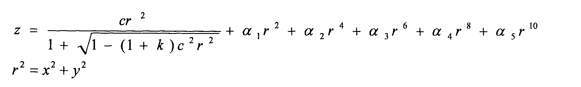
- the surface with surface number 2 is an aspherical surface and is defined by a coefficient as shown in FIG. 6D.
- k is a conic coefficient
- ⁇ i is an aspheric coefficient.
- the zaku amount z is given by the following equation.
- the phosphor portion 14 is arranged at a position determined by the focal length corresponding to the wavelength of the fluorescence of the collimator lens 15, so that the green color emitted from the phosphor portion 14 is Most of the fluorescence (diverged light) can be converted into a parallel light beam, thereby improving the light utilization efficiency.
- the collimator lens 15 since the collimator lens 15 includes high-dispersion lenses 15a and 15b having a positive power and a low-dispersion lens 15c having a negative power, the focal length changes depending on the wavelength. Therefore, when the phosphor portion 14 is arranged at a position determined by the focal length corresponding to the fluorescence wavelength of the collimator lens 15, the collimator lens 15 receives the excitation light from the excitation light sources 12 and 13 on the phosphor portion 14 to some extent. The light is focused in a state having a defocus amount of. Thereby, since the light energy density per unit area falls, the damage to the fluorescent substance by excitation light can be reduced.
- the rotational drive system as described in Patent Document 1 is unnecessary, so that the device can be reduced in size, and the device cost can be reduced. .
- the light source device of this embodiment has the following operational effects.
- the projection type display device shown in FIG. 5 there is a restriction called etendue determined by the area of the excitation light irradiation region on the phosphor portion 14 and the divergence angle of the fluorescence emitted from the excitation light irradiation region. .
- the value of the product of the area of the excitation light irradiation region (more specifically, the fluorescent emission area) and the divergence angle is taken as the capture angle (solid angle) determined by the area of the DMD 46 as the display element and the F number of the projection optical system 47. ) Or less, it is possible to capture and project the fluorescent light from the phosphor portion 14 without leaving any excess.
- the light use efficiency is almost the same regardless of the size of the excitation light irradiation region (spot size) on the phosphor portion 14 as long as it is within the range restricted by etendue restrictions.
- the panel side etendue is expressed by the following formula.
- E panel indicates the panel side etendue
- S panel indicates the panel area
- Fno indicates the F number of the projection optical system 47.
- FIG. 6B shows the result of obtaining the panel-side etendue according to the panel size using the above formula.
- FIG. 6B shows the values of etendue (mm 2 / mm) when the F number is changed to 1.8, 2, 2.2, 2.4 for each of the 0.2 inch panel and the 0.3 inch panel. sr) is shown.
- the aspect ratio of the 0.2 inch panel and the 0.3 inch panel is 4: 3.
- the etendue on the light source side is expressed by the following equation.
- the E light source indicates the etendue of the light source
- the S light source indicates the light emission area of the light source
- ⁇ indicates the solid angle of the light source
- FIG. 6C shows the result of obtaining the maximum light emitting area from the result of obtaining the etendue of the light source according to the panel size using the above formula.
- FIG. 6C shows the values of the maximum light emitting area (mm) when the F number is changed to 1.8, 2, 2.2, 2.4 for each of the 0.2 inch panel and the 0.3 inch panel. )It is shown.
- the emission area (emission size) of the light source that can be received by the 0.2-inch panel when the etendue constraint is satisfied is up to ⁇ 0.8 mm.
- the emission area of the fluorescence is larger than the spot size (beam diameter) of the excitation light on the phosphor portion 14.
- the spot size is doubled with respect to the spot size of the excitation light
- the F number is 2.4 and the panel size is 0.2 inches
- the excitation light By limiting the spot size to ⁇ 0.4 mm or less, the etendue constraint is satisfied. In other words, if the spot size of the excitation light is ⁇ 0.4 mm or less, the light utilization efficiency of the projection display device is reduced in order to satisfy the etendue restrictions regardless of the spot size. Absent.
- the spot size of the excitation light is reduced, the phosphor may be damaged. Therefore, it is desirable to increase the spot size of the excitation light within a range that satisfies the etendue restrictions.
- the collimator lens 15 has a role of condensing excitation light on the phosphor portion 14 and a role of converting the fluorescent light into a parallel light flux.
- the collimating lens 15 in the wavelength region of the excitation light It is desirable that the focal length is different from the focal length of the collimating lens 15 in the fluorescent (green) wavelength region.
- the collimator lens 15 is configured by combining a lens having a positive power and a lens having a negative lens power based on a concept opposite to chromatic aberration correction.
- a lens having power is made of high dispersion glass, and a lens having negative power is made of low dispersion glass, so that chromatic aberration is positively generated so that the focal length varies depending on the wavelength.
- the collimator lens 15 condenses the excitation light on the phosphor portion 14 in a spot size having a certain size within the irradiation region range determined by the above-mentioned etendue restrictions. Thereby, the light use efficiency fall can be suppressed and the damage to a fluorescent substance can be reduced.
- the collimator lens 15 is configured such that the focal length at the excitation light wavelength (eg, blue) is 5% to 10% shorter than the focal length at the fluorescence wavelength (eg, green), thereby satisfying the etendue restrictions.
- the spot size of the excitation light can be increased to some extent. As a result, it is possible to reliably suppress a decrease in light utilization efficiency and reduce the damage of the excitation light to the phosphor.
- chromatic aberration when chromatic aberration is controlled only by a lens having a positive power, the control depends only on the Abbe number. Since the Abbe number depends on the glass material used for the lens, a collimator lens constituted only by a lens having a positive power has a problem that the degree of design freedom regarding the control of chromatic aberration is small.
- the chromatic aberration of the collimator lens 15 is controlled by a combination of a lens having a positive power and a lens having a negative power.
- the chromatic aberration can be controlled by the relationship between the Abbe number of the lens having a positive power and the Abbe number of a lens having a negative power, the degree of design freedom regarding the control of the chromatic aberration is increased.
- the light source device of the present embodiment described above is an example of the present invention, and the configuration thereof can be modified by those skilled in the art without departing from the spirit of the invention.
- the number of the high-dispersion lens having positive power and the low-dispersion lens having negative power constituting the collimator lens 15 may be one or plural.
- the number of excitation light sources is not limited to two.
- the number of excitation light sources may be one, or three or more.
- FIG. 7 is a schematic diagram showing a configuration of an illumination device to which the light source device of the present invention is applied.
- the illumination device is used in a projection display device such as a projector, and includes a red laser 10, a blue laser 11, excitation light sources 12, 13, a phosphor portion 14, collimator lenses 15-19, Dichroic mirrors 51a, 51b, 51c and optical path changing mirrors 52, 53 are provided.
- the optical path of the red laser light output from the red laser 10 the optical path of the blue laser light output from the blue laser 11, the optical path of the excitation light output from the excitation light sources 12 and 13, and the phosphor wheel
- the optical paths of green fluorescence emitted from 14 are indicated by solid lines (thick lines) with arrows.
- a white arrow is light obtained by combining red laser light, blue laser light, and green fluorescence, and is output light of the illumination device of the present embodiment.
- Each of the optical paths of each color shows only the optical path of the central ray, and actually consists of a bundle of rays composed of a plurality of rays.
- the red laser 10 and the blue laser 11 are solid light sources such as semiconductor lasers and LEDs typified by laser diodes.
- the red laser 10 outputs S-polarized laser light having a peak wavelength in the red wavelength region (hereinafter simply referred to as red laser light).
- the blue laser 11 outputs S-polarized laser light having a peak wavelength in the blue wavelength region (hereinafter simply referred to as blue laser light).
- the peak wavelength of the output light of the excitation light sources 12 and 13 may be the same as that of the blue laser 11 or may be different.
- the collimator lens 16 converts the red laser light (diverged light) output from the red laser 10 into a parallel light beam.
- the collimator lens 17 converts blue laser light (diverged light) output from the blue laser 11 into a parallel light beam.
- the collimator lens 18 converts the excitation light (divergent light) output from the excitation light source 12 into a parallel light beam.
- the collimator lens 19 converts the excitation light (divergent light) output from the excitation light source 13 into a parallel light beam.
- Each of the red laser 10, the blue laser 11, and the excitation light sources 12 and 13 is disposed so as to emit light in the same direction. More specifically, the optical axes of the red laser 10, the blue laser 11, and the excitation light sources 12 and 13 are parallel to each other.
- Each of the dichroic mirrors 51a to 51c is made of a dielectric multilayer film.
- the dichroic mirrors 51a to 51c are arranged so as to intersect with the central ray of the green fluorescent light beam emitted from the phosphor part 14.
- the dichroic mirrors 51a to 51c are arranged in this order from the phosphor part 14 side.
- the dichroic mirrors 51a to 51c may be arranged so as to be orthogonal to a plane including the central ray of the fluorescent light beam.
- the film characteristics of the dichroic mirrors 51a and 51b are the same. That is, both the dichroic mirrors 51a and 51b have the characteristics shown in FIG.
- the film characteristics of the dichroic mirror 51c are different from those of the dichroic mirrors 51a and 51b.
- FIG. 8 shows spectral transmission characteristics of the dichroic mirror 51c with respect to P-polarized light and S-polarized light.
- the solid line shows the spectral transmission characteristic for S-polarized light
- the dotted line shows the spectral transmission characteristic for P-polarized light.
- R-LD is a spectrum of red laser light output from the red laser 10.
- the cutoff wavelength of the dichroic mirror 51c with respect to light incident as S-polarized light is set so as to reflect light in the red wavelength range or higher and transmit light in other wavelength ranges (including green and blue wavelength ranges).
- the cut-off wavelength of the dichroic mirror 51c for light incident as P-polarized light is set to be longer than the cut-off wavelength for S-polarized light.
- the setting of the cutoff wavelength can be adjusted by the material of the dielectric multilayer film, the number of stacked layers, the film thickness, the refractive index, and the like.
- S-polarized light having a wavelength greater than or equal to the red wavelength band is reflected, and S-polarized light and P-polarized light in the green and blue wavelength bands are transmitted.
- the excitation light output from the excitation light source 12 and converted into a parallel light beam by the collimator lens 18 is incident on the dichroic mirror 51a at an incident angle of about 45 °.
- the excitation light output from the excitation light source 13 and converted into a parallel light beam by the collimator lens 19 enters the dichroic mirror 51a through the mirrors 52 and 53 at an incident angle of about 45 °.
- the dichroic mirror 51 a reflects the incident excitation light toward the phosphor portion 14.
- the excitation light reflected by the dichroic mirror 51 a is condensed on the phosphor region of the phosphor unit 14 via the collimator lens 15.
- the phosphor In the phosphor region of the phosphor part 14, the phosphor is excited by irradiation with excitation light. Green fluorescence is emitted from the excited phosphor.
- the green fluorescence (diverging light) emitted from the phosphor region of the phosphor part 14 is collimated by the collimator lens 15 and then enters the dichroic mirror 51a.
- the dichroic mirror 51a transmits the incident green fluorescence.
- the transmitted green fluorescent light beam from the dichroic mirror 51a is incident on the dichroic mirror 51b at an incident angle of about 45 °.
- the dichroic mirror 51b is disposed at the intersection of the optical axis of the blue laser 11 and the green fluorescent light beam from the fluorescent part 14 (more specifically, the optical axis of the system including the fluorescent part 14 and the collimator lens 15).
- the blue laser beam from the blue laser 11 is incident on the dichroic mirror 51b at an incident angle of about 45 °.
- the dichroic mirror 51b reflects the blue laser light from the blue laser 11 toward the dichroic mirror 51c, and transmits the green fluorescent transmitted light from the dichroic mirror 51a.
- the blue laser light from the blue laser 11 and the green fluorescence from the dichroic mirror 51a are color-synthesized.
- the luminous flux (blue laser light + green fluorescence) from the dichroic mirror 51b is incident on the dichroic mirror 51c at an incident angle of about 45 °.
- the dichroic mirror 51c is arranged at the intersection of the optical axis of the red laser 10 and the green fluorescent light beam from the fluorescent part 14 (more specifically, the optical axis of the system including the fluorescent part 14 and the collimator lens 15). Has been.
- the red laser light from the red laser 10 is incident on the dichroic mirror 51c at an incident angle of about 45 °.
- the dichroic mirror 51c reflects the red laser light from the red laser 10 and transmits the light beam (blue laser light + green fluorescence) from the dichroic mirror 51b.
- the red laser light from the red laser 10 and the luminous flux (blue laser light + green fluorescence) from the dichroic mirror 51b are color-synthesized.
- the dichroic mirrors 51b and 51c are color synthesis means for synthesizing blue laser light, green fluorescence, and red laser light.
- a light beam (blue laser light + green fluorescence + red laser light) from the dichroic mirror 51c is output light of the illumination device of the present embodiment.
- the lighting device of the present embodiment described above also exhibits the same operational effects as those of the light source device described above.
- dichroic mirrors 51a to 51c may be formed of rectangular parallelepiped dichroic prisms.
- the dichroic prism includes first and second right-angle prisms, a trapezoidal prism, and a parallelogram prism.
- Each of the first and second right-angle prisms has a right-angle surface and a slope, and the slope of the first right-angle prism is joined to one of the opposite slopes of the trapezoidal prism, and the dichroic mirror 51a is joined to the joint face.
- a dichroic film corresponding to is formed.
- One of the opposed slopes of the parallelogram prism is joined to the other of the opposed slopes of the trapezoidal prism, and a dichroic film corresponding to the dichroic mirror 51b is formed on the joined surface.
- the other of the opposed inclined surfaces of the parallelogram prism is bonded to the inclined surface of the second right-angle prism, and a dichroic film corresponding to the dichroic mirror 51c is formed on the bonded surface.
- the dichroic prism may be composed of first to third right-angle prisms and parallelogram-shaped prisms.
- Each of the first to third right-angle prisms has a right-angle surface and a slope, and the slope of the first right-angle prism is joined to one face of the right-angle face of the second right-angle prism, and the dichroic is joined to the joint face.
- a dichroic film corresponding to the mirror 51a is formed.
- One of the two opposing faces of the parallelogram prism is joined to the other face of the second right-angle prism, and a dichroic film corresponding to the dichroic mirror 51b is formed on the joined face.
- the other of the two opposing surfaces of the parallelogram prism is joined to the slope of the third right-angle prism, and a dichroic film corresponding to the dichroic mirror 51c is formed on the joined surface.
- a cross dichroic prism may be used instead of the dichroic mirrors 51b and 51c.
- the cross dichroic prism is composed of first to fourth right-angle prisms whose right-angle surfaces are joined to each other.
- a uniform first plane is formed by the joint surfaces of the first and second right-angle prisms and the joint surfaces of the third and fourth right-angle prisms, and the same film as the dichroic mirror 51b is formed on the first plane.
- a dichroic film having characteristics is formed.
- a uniform second plane intersecting the first plane is formed by the joint surfaces of the first and fourth right-angle prisms and the second and third right-angle prisms.
- the second plane In addition, a dichroic film having the same film characteristics as the dichroic mirror 51c is formed.
- an optical system or a light guide means for guiding the light output from the dichroic mirror 51c may be provided.
- the positions of the dichroic mirrors 51b and 51c may be reversed. That is, the dichroic mirrors 51a, 51c, 51b may be arranged in this order from the phosphor part 14 side. In this case, the positions of the red laser 10 and the blue laser 11 are also reversed.
- optical path changing mirrors 52 and 53 instead of the optical path changing mirrors 52 and 53, parallelogram prisms may be used.
- a light source device includes a phosphor part that emits fluorescence when excited by excitation light, an excitation light source part that outputs excitation light, and excitation light output from the excitation light source part. And a collimating lens provided between the reflecting unit and the phosphor unit, the focal length of which varies depending on the wavelength, and which reflects the light emitted from the phosphor unit.
- the phosphor portion is disposed at a position determined by the focal length corresponding to the wavelength of the fluorescence emitted from the phosphor portion of the collimator lens.
- the collimator lens has at least one first lens having negative power and at least one second lens having positive power and an Abbe number smaller than the first lens.
- the excitation light source unit may be composed of the excitation light sources 12 and 13 shown in FIG.
- the reflection unit may be configured by the dichroic mirror 51a illustrated in FIG.
- the collimator lens may be configured by the collimator lens 15 shown in FIG.
- the light source device of the present invention described above can be applied to all projection display devices represented by projectors.
- the projection display device combines the first and second solid light sources having different emission colors, the fluorescence output from the light source device, and the first and second lights output from the first and second solid light sources.
- Color synthesizing means a display element that spatially modulates the synthesized light synthesized by the color synthesizing means to generate modulated light, and a projection optical system that projects the modulated light generated by the display element.
- the display element is a DMD or a liquid crystal panel.
- FIG. 9 shows an example of a projection display device provided with the light source device of the present invention.
- the projection display device includes a DMD 46 as a display element, the illumination device of the second embodiment, an optical system for guiding light from the illumination device to the DMD 46, and an image formed by the DMD 46.
- a projection optical system 47 that projects light (modulated light) onto a screen (not shown).
- the optical system includes fly-eye lenses 40 and 41, a field lens 42, a mirror 43, a condenser lens 44, and an internal total reflection (TIR) prism 45. These are the same as those shown in FIG.
- luminous fluxes of red, green and blue colors are emitted from the color synthesis prism 20 in a time-sharing manner.
- Image light of each color can be obtained by spatially modulating the light flux of each color emitted in this time division using the DMD 46.
- the light source device of the other embodiment described above may be used.
Landscapes
- Physics & Mathematics (AREA)
- General Physics & Mathematics (AREA)
- Engineering & Computer Science (AREA)
- Optics & Photonics (AREA)
- Multimedia (AREA)
- General Engineering & Computer Science (AREA)
- Signal Processing (AREA)
- Projection Apparatus (AREA)
- Non-Portable Lighting Devices Or Systems Thereof (AREA)
- Lenses (AREA)
Abstract
Description
励起光により励起されることで蛍光を放出する蛍光体部と、
前記励起光を出力する励起光源部と、
前記励起光源部から出力された前記励起光を前記蛍光体部に向けて反射するとともに、前記蛍光体部から放出された前記蛍光を透過する反射部と、
前記反射部と前記蛍光体部の間に設けられた、焦点距離が波長により異なるコリメータレンズと、を有し、
前記蛍光体部は、前記コリメータレンズの、前記蛍光体部から放出される前記蛍光の波長における焦点距離によって定められた位置に配置されており、
前記コリメータレンズは、
負のパワーを持つ少なくとも1つの第1のレンズと、
正のパワーを持ち、かつ、アッベ数が前記第1のレンズより小さい、少なくとも1つの第2のレンズと、を有する。 In order to achieve the above object, the light source device of the present invention comprises:
A phosphor part that emits fluorescence when excited by excitation light; and
An excitation light source unit that outputs the excitation light;
A reflection unit that reflects the excitation light output from the excitation light source unit toward the phosphor unit and transmits the fluorescence emitted from the phosphor unit;
A collimator lens provided between the reflecting portion and the phosphor portion, and having a focal length different depending on a wavelength;
The phosphor part is disposed at a position determined by a focal length of the wavelength of the fluorescence emitted from the phosphor part of the collimator lens,
The collimator lens is
At least one first lens having negative power;
And at least one second lens having a positive power and an Abbe number smaller than that of the first lens.
上記の光源装置と、
発光色が異なる第1および第2の固体光源と、
前記光源装置から出力された蛍光と前記第1および第2の固体光源から出力された第1および第2の光とを合成する色合成手段と、を有する。 The lighting device of the present invention is
The above light source device;
First and second solid-state light sources having different emission colors;
Color synthesis means for synthesizing the fluorescence output from the light source device and the first and second lights output from the first and second solid-state light sources.
上記の光源装置と、
発光色が異なる第1および第2の固体光源と、
前記光源装置から出力された蛍光と前記第1および第2の固体光源から出力された第1および第2の光とを合成する色合成手段と、
前記色合成手段により合成された合成光を空間的に変調して変調光を生成する表示素子と、
前記表示素子で生成された前記変調光を投射する投射光学系と、を有する。 The projection display device of the present invention is
The above light source device;
First and second solid-state light sources having different emission colors;
Color combining means for combining the fluorescence output from the light source device with the first and second lights output from the first and second solid state light sources;
A display element that spatially modulates the combined light combined by the color combining means to generate modulated light;
A projection optical system that projects the modulated light generated by the display element.
14 蛍光体部
15、18、19 コリメータレンズ
51a ダイクロイックミラー 12, 13
ここで、「d」はd線(587.5618nm)を示し、「F」はF線(486.1327nm)を示し、「C」はC線(656.2725nm)を示す。アッベ数νdの値が大きい場合を低分散と言い、逆にアッベ数νdの値が小さい場合を高分散と言う。一般に、アッベ数νdの値が50より大きな低分散ガラスをクラウンガラスと呼び、逆に、アッベ数νdの値が50以下の高分散ガラスをフリントガラスと呼ぶ。 ν d = (n d −1) ÷ (n F −n C )
Here, “d” indicates the d line (587.5618 nm), “F” indicates the F line (4866.1327 nm), and “C” indicates the C line (6566.2725 nm). A case where the Abbe number ν d is large is called low dispersion, and a case where the Abbe number ν d is small is called high dispersion. In general, a low dispersion glass having an Abbe number ν d greater than 50 is called a crown glass, and conversely, a high dispersion glass having an Abbe number ν d of 50 or less is called a flint glass.

本他の実施形態の光源装置は、励起光により励起されることで蛍光を放出する蛍光体部と、励起光を出力する励起光源部と、励起光源部から出力された励起光を蛍光体部に向けて反射するとともに、蛍光体部から放出された蛍光を透過する反射部と、反射部と蛍光体部の間に設けられた、焦点距離が波長により異なるコリメータレンズと、を有する。 (Other embodiments)
A light source device according to another embodiment includes a phosphor part that emits fluorescence when excited by excitation light, an excitation light source part that outputs excitation light, and excitation light output from the excitation light source part. And a collimating lens provided between the reflecting unit and the phosphor unit, the focal length of which varies depending on the wavelength, and which reflects the light emitted from the phosphor unit.
Claims (6)
- 励起光により励起されることで蛍光を放出する蛍光体部と、
前記励起光を出力する励起光源部と、
前記励起光源部から出力された前記励起光を前記蛍光体部に向けて反射するとともに、前記蛍光体部から放出された前記蛍光を透過する反射部と、
前記反射部と前記蛍光体部の間に設けられた、焦点距離が波長により異なるコリメータレンズと、を有し、
前記蛍光体部は、前記コリメータレンズの、前記蛍光体部から放出される前記蛍光の波長における焦点距離によって定められた位置に配置されており、
前記コリメータレンズは、
負のパワーを持つ少なくとも1つの第1のレンズと、
正のパワーを持ち、かつ、アッベ数が前記第1のレンズより小さい、少なくとも1つの第2のレンズと、を有する、光源装置。 A phosphor part that emits fluorescence when excited by excitation light; and
An excitation light source unit that outputs the excitation light;
A reflection unit that reflects the excitation light output from the excitation light source unit toward the phosphor unit and transmits the fluorescence emitted from the phosphor unit;
A collimator lens provided between the reflecting portion and the phosphor portion, and having a focal length different depending on a wavelength;
The phosphor part is disposed at a position determined by a focal length of the wavelength of the fluorescence emitted from the phosphor part of the collimator lens,
The collimator lens is
At least one first lens having negative power;
A light source device having at least one second lens having positive power and an Abbe number smaller than that of the first lens. - 前記第2のレンズは、前記第1のレンズよりも前記蛍光体部側に配置されている、請求の範囲第1項に記載の光源装置。 The light source device according to claim 1, wherein the second lens is disposed closer to the phosphor portion than the first lens.
- 前記コリメータレンズは、前記励起光源部から出力される前記励起光の波長における焦点距離が前記蛍光体部から放出される前記蛍光の波長における焦点距離に対して5%~10%短くなるように構成されている、請求の範囲第1項または第2項に記載の光源装置。 The collimator lens is configured such that the focal length at the wavelength of the excitation light output from the excitation light source unit is 5% to 10% shorter than the focal length at the wavelength of the fluorescence emitted from the phosphor unit. The light source device according to claim 1, wherein the light source device is a light source device.
- 前記励起光源部は、第1および第2の励起光源を有し、前記反射部で反射された前記第1の励起光源からの励起光の中心光線と、前記反射部で反射された前記第2の励起光源からの励起光の中心光線とは、前記コリメータレンズの光軸を挟んで線対称な位置関係にある、請求の範囲第1項から第3項のいずれか1項に記載の光源装置。 The excitation light source unit includes first and second excitation light sources, and a central ray of excitation light from the first excitation light source reflected by the reflection unit and the second light reflected by the reflection unit. 4. The light source device according to claim 1, wherein the central light beam of the excitation light from the excitation light source is in a line-symmetrical positional relationship across the optical axis of the collimator lens. .
- 請求の範囲第1項から第4項のいずれか1項に記載の光源装置と、
発光色が異なる第1および第2の固体光源と、
前記光源装置から出力された蛍光と前記第1および第2の固体光源から出力された第1および第2の光とを合成する色合成手段と、を有する照明装置。 The light source device according to any one of claims 1 to 4,
First and second solid-state light sources having different emission colors;
An illumination device comprising: color combining means for combining the fluorescence output from the light source device with the first and second lights output from the first and second solid light sources. - 請求の範囲第1項から第4項のいずれか1項に記載の光源装置と、
発光色が異なる第1および第2の固体光源と、
前記光源装置から出力された蛍光と前記第1および第2の固体光源から出力された第1および第2の光とを合成する色合成手段と、
前記色合成手段により合成された合成光を空間的に変調して変調光を生成する表示素子と、
前記表示素子で生成された前記変調光を投射する投射光学系と、を有する投射型表示装置。 The light source device according to any one of claims 1 to 4,
First and second solid-state light sources having different emission colors;
Color combining means for combining the fluorescence output from the light source device with the first and second lights output from the first and second solid state light sources;
A display element that spatially modulates the combined light combined by the color combining means to generate modulated light;
A projection optical system that projects the modulated light generated by the display element.
Priority Applications (5)
| Application Number | Priority Date | Filing Date | Title |
|---|---|---|---|
| EP10859721.2A EP2642178B1 (en) | 2010-11-17 | 2010-11-17 | Light source apparatus, lighting apparatus, and projection-type display apparatus |
| CN201080070233.9A CN103221735B (en) | 2010-11-17 | 2010-11-17 | Light source apparatus, lighting apparatus, and projection-type display apparatus |
| PCT/JP2010/070484 WO2012066654A1 (en) | 2010-11-17 | 2010-11-17 | Light source apparatus, lighting apparatus, and projection-type display apparatus |
| US13/883,977 US9046750B2 (en) | 2010-11-17 | 2010-11-17 | Projector light source apparatus having collimator disposed between excitation light source and phosphor element |
| JP2012544049A JP5497912B2 (en) | 2010-11-17 | 2010-11-17 | Light source device, illumination device, and projection display device |
Applications Claiming Priority (1)
| Application Number | Priority Date | Filing Date | Title |
|---|---|---|---|
| PCT/JP2010/070484 WO2012066654A1 (en) | 2010-11-17 | 2010-11-17 | Light source apparatus, lighting apparatus, and projection-type display apparatus |
Publications (1)
| Publication Number | Publication Date |
|---|---|
| WO2012066654A1 true WO2012066654A1 (en) | 2012-05-24 |
Family
ID=46083616
Family Applications (1)
| Application Number | Title | Priority Date | Filing Date |
|---|---|---|---|
| PCT/JP2010/070484 WO2012066654A1 (en) | 2010-11-17 | 2010-11-17 | Light source apparatus, lighting apparatus, and projection-type display apparatus |
Country Status (5)
| Country | Link |
|---|---|
| US (1) | US9046750B2 (en) |
| EP (1) | EP2642178B1 (en) |
| JP (1) | JP5497912B2 (en) |
| CN (1) | CN103221735B (en) |
| WO (1) | WO2012066654A1 (en) |
Cited By (17)
| Publication number | Priority date | Publication date | Assignee | Title |
|---|---|---|---|---|
| WO2014068742A1 (en) * | 2012-11-01 | 2014-05-08 | 日立マクセル株式会社 | Light source device and projection-type image display device |
| US20140198303A1 (en) * | 2013-01-17 | 2014-07-17 | Delta Electronics, Inc. | Optical system |
| WO2014121707A1 (en) * | 2013-02-05 | 2014-08-14 | 深圳市光峰光电技术有限公司 | Light source system with compact structure |
| WO2015087512A1 (en) * | 2013-12-11 | 2015-06-18 | Canon Kabushiki Kaisha | Illumination optical system, image projection apparatus, and control method thereof |
| JP2015135465A (en) * | 2013-12-20 | 2015-07-27 | カシオ計算機株式会社 | Light source unit and projection device |
| WO2015189947A1 (en) * | 2014-06-12 | 2015-12-17 | Necディスプレイソリューションズ株式会社 | Light source device and projector |
| JP5922781B2 (en) * | 2012-09-10 | 2016-05-24 | 三菱電機株式会社 | Light source device |
| JP2016151643A (en) * | 2015-02-17 | 2016-08-22 | セイコーエプソン株式会社 | Illuminator and projector |
| JP2017073245A (en) * | 2015-10-06 | 2017-04-13 | ウシオ電機株式会社 | Fluorescent light source device |
| WO2017154371A1 (en) * | 2016-03-07 | 2017-09-14 | ソニー株式会社 | Light source device and electronic device |
| WO2017153986A1 (en) | 2016-03-08 | 2017-09-14 | Technion Research & Development Foundation Limited | Disinfection and removal of nitrogen species from saline aquaculture systems |
| JP2017194523A (en) * | 2016-04-19 | 2017-10-26 | キヤノン株式会社 | Light source device and image projection device |
| US10037734B2 (en) | 2013-12-11 | 2018-07-31 | Canon Kabushiki Kaisha | Display apparatus and control method |
| US11579518B2 (en) | 2020-11-06 | 2023-02-14 | Canon Kabushiki Kaisha | Light source device and image projection apparatus including the same |
| US11579519B2 (en) | 2020-03-23 | 2023-02-14 | Seiko Epson Corporation | Light source device, illumination device, and projector |
| JP7341740B2 (en) | 2019-06-12 | 2023-09-11 | キヤノン株式会社 | Light source device and image projection device |
| US11815796B2 (en) | 2021-03-29 | 2023-11-14 | Seiko Epson Corporation | Light source apparatus and projector |
Families Citing this family (31)
| Publication number | Priority date | Publication date | Assignee | Title |
|---|---|---|---|---|
| US8955985B2 (en) * | 2010-10-19 | 2015-02-17 | Nec Display Solutions, Ltd. | Lighting device and projection-type display device using same |
| WO2012143990A1 (en) * | 2011-04-18 | 2012-10-26 | Necディスプレイソリューションズ株式会社 | Projection image display device |
| JP5914878B2 (en) * | 2011-04-20 | 2016-05-11 | パナソニックIpマネジメント株式会社 | Light source device and projection display device |
| WO2013008323A1 (en) | 2011-07-13 | 2013-01-17 | Necディスプレイソリューションズ株式会社 | Light source device and projection-type display device |
| TWI450019B (en) * | 2011-10-06 | 2014-08-21 | Acer Inc | Illumination system and projection apparatus |
| CN102789121A (en) * | 2012-04-10 | 2012-11-21 | 海信集团有限公司 | Projection display light source |
| CN103376634B (en) * | 2012-04-24 | 2015-11-18 | 中强光电股份有限公司 | Light source module and projection arrangement |
| JP2014041440A (en) * | 2012-08-21 | 2014-03-06 | Sony Corp | Electronic device, illuminating device, illuminating method, and method of manufacturing illuminating device |
| CN103615672B (en) * | 2013-10-28 | 2019-09-10 | 杨毅 | Light source |
| KR20150123064A (en) | 2014-04-24 | 2015-11-03 | 삼성전자주식회사 | Illumination apparatus and projection-type image display apparatus having the same |
| CN105223761B (en) | 2014-07-01 | 2017-05-24 | 中强光电股份有限公司 | Projection device and illumination system |
| JP6578631B2 (en) * | 2014-07-09 | 2019-09-25 | セイコーエプソン株式会社 | Lighting device and projector |
| KR20160019809A (en) * | 2014-08-12 | 2016-02-22 | 현대모비스 주식회사 | Laser Optical System and Lamp for Vehicle having the same |
| DE102014223510A1 (en) | 2014-11-18 | 2016-05-19 | Osram Gmbh | Lighting device with pumping light unit and phosphor element |
| DE102015209968A1 (en) * | 2015-05-29 | 2016-12-01 | Osram Gmbh | Lighting device with pump radiation unit and phosphor element |
| CN106523955B (en) * | 2015-09-14 | 2019-10-11 | 中强光电股份有限公司 | Lighting system and projection arrangement |
| CN107272314B (en) * | 2016-04-06 | 2022-01-18 | 上海蓝湖照明科技有限公司 | Light-emitting device and related projection system and lighting system |
| US10215367B2 (en) | 2016-11-09 | 2019-02-26 | Christie Digital Systems Usa, Inc. | Apparatus for wavelength conversion |
| CN108802986B (en) * | 2017-05-02 | 2020-06-19 | 台达电子工业股份有限公司 | Laser projection light source |
| US10323928B2 (en) | 2017-06-16 | 2019-06-18 | Mitutoyo Corporation | Optical configuration for measurement device using emitter material configuration |
| US10006757B1 (en) | 2017-06-16 | 2018-06-26 | Mitutoyo Corporation | Optical configuration for measurement device using emitter material configuration with quadrant photodetectors |
| EP3688404B1 (en) | 2017-09-29 | 2023-06-07 | Mitutoyo Corporation | Compact measurement device configuration for integrating complex circuits |
| CN107884372A (en) * | 2017-09-30 | 2018-04-06 | 维科托(北京)科技有限公司 | For the incidence system of atomic fluorescence detection device and the mounting bracket of excitation source |
| JP6987347B2 (en) * | 2018-03-29 | 2021-12-22 | マクセル株式会社 | projector |
| CN110780428A (en) * | 2018-04-20 | 2020-02-11 | 美国奈维特公司 | Modular zoom lens with high optical expansion for machine vision |
| CN108761981B (en) * | 2018-04-28 | 2020-10-20 | 苏州佳世达光电有限公司 | Projector with a light source |
| TWI681246B (en) * | 2018-11-05 | 2020-01-01 | 揚明光學股份有限公司 | Heat dissipation device and projector |
| JP7268421B2 (en) * | 2019-03-18 | 2023-05-08 | 株式会社リコー | Light source optical system, light source device and image projection device |
| CN111722465A (en) * | 2019-03-20 | 2020-09-29 | 株式会社理光 | Light source device, image projection device, and light source optical system |
| WO2021084449A1 (en) * | 2019-11-01 | 2021-05-06 | Ricoh Company, Ltd. | Light-source device, image projection apparatus, and light-source optical system |
| CN114371587A (en) * | 2020-10-14 | 2022-04-19 | 青岛海信激光显示股份有限公司 | Projection optical system |
Citations (3)
| Publication number | Priority date | Publication date | Assignee | Title |
|---|---|---|---|---|
| JP2003295319A (en) * | 2002-04-04 | 2003-10-15 | Nitto Kogaku Kk | Light source unit and projector |
| JP2004327361A (en) * | 2003-04-28 | 2004-11-18 | Seiko Epson Corp | Lighting device and projection type display device |
| JP2004341105A (en) | 2003-05-14 | 2004-12-02 | Nec Viewtechnology Ltd | Projection type display device |
Family Cites Families (44)
| Publication number | Priority date | Publication date | Assignee | Title |
|---|---|---|---|---|
| KR100403599B1 (en) | 2001-11-06 | 2003-10-30 | 삼성전자주식회사 | Illumination system and a projection system imploying it |
| US7070300B2 (en) * | 2004-06-04 | 2006-07-04 | Philips Lumileds Lighting Company, Llc | Remote wavelength conversion in an illumination device |
| KR100644632B1 (en) | 2004-10-01 | 2006-11-10 | 삼성전자주식회사 | Illumination unit adopting LED and projection display using the same |
| US7445340B2 (en) | 2005-05-19 | 2008-11-04 | 3M Innovative Properties Company | Polarized, LED-based illumination source |
| JP4978831B2 (en) | 2006-07-19 | 2012-07-18 | 株式会社ニコン | Projector optical system |
| EP2050147A2 (en) | 2006-07-31 | 2009-04-22 | 3M Innovative Properties Company | Led source with hollow collection lens |
| US7547114B2 (en) * | 2007-07-30 | 2009-06-16 | Ylx Corp. | Multicolor illumination device using moving plate with wavelength conversion materials |
| JP5105165B2 (en) | 2007-12-18 | 2012-12-19 | カシオ計算機株式会社 | Light source device and projector |
| JP4662183B2 (en) * | 2008-04-16 | 2011-03-30 | カシオ計算機株式会社 | Light source device and projector |
| JP4662184B2 (en) * | 2008-04-25 | 2011-03-30 | カシオ計算機株式会社 | Light source device and projector |
| JP4662185B2 (en) * | 2008-05-15 | 2011-03-30 | カシオ計算機株式会社 | Light source device and projector |
| WO2010068974A1 (en) | 2008-12-15 | 2010-06-24 | Digislide Holdings Limited | An optical engine for miniature projection utilising a retro-reflective polarisation recycling system and a reflective field sequential or colour filter lcos panel |
| JP4692623B2 (en) * | 2008-12-17 | 2011-06-01 | カシオ計算機株式会社 | Light source device and light source control method |
| CN101825836A (en) * | 2009-03-02 | 2010-09-08 | 鸿富锦精密工业(深圳)有限公司 | Light source system |
| JP4900736B2 (en) * | 2009-03-31 | 2012-03-21 | カシオ計算機株式会社 | Light source device and projector |
| JP4883376B2 (en) * | 2009-06-30 | 2012-02-22 | カシオ計算機株式会社 | Phosphor substrate, light source device, projector |
| JP4711155B2 (en) * | 2009-06-30 | 2011-06-29 | カシオ計算機株式会社 | Light source device and projector |
| JP4711156B2 (en) * | 2009-06-30 | 2011-06-29 | カシオ計算機株式会社 | Light source device and projector |
| JP4711021B2 (en) * | 2009-06-30 | 2011-06-29 | カシオ計算機株式会社 | Projection device |
| JP4742349B2 (en) * | 2009-06-30 | 2011-08-10 | カシオ計算機株式会社 | Light source device and projector |
| JP4756403B2 (en) * | 2009-06-30 | 2011-08-24 | カシオ計算機株式会社 | Light source device and projector |
| JP4711154B2 (en) * | 2009-06-30 | 2011-06-29 | カシオ計算機株式会社 | Light source device and projector |
| JP4924677B2 (en) * | 2009-08-21 | 2012-04-25 | カシオ計算機株式会社 | Light source device, projection device, and projection method |
| JP5406638B2 (en) * | 2009-08-31 | 2014-02-05 | カシオ計算機株式会社 | Light source device and projector |
| JP5370764B2 (en) * | 2009-09-15 | 2013-12-18 | カシオ計算機株式会社 | Light source device and projector |
| JP5796272B2 (en) * | 2009-09-28 | 2015-10-21 | カシオ計算機株式会社 | Light source device, projection device, and projection method |
| JP2011075919A (en) * | 2009-09-30 | 2011-04-14 | Casio Computer Co Ltd | Light source device, projection apparatus and projection method |
| JP5500341B2 (en) * | 2009-10-28 | 2014-05-21 | カシオ計算機株式会社 | Light source unit and projector |
| JP5713168B2 (en) * | 2009-10-28 | 2015-05-07 | カシオ計算機株式会社 | Light source unit and projector |
| JP4873276B2 (en) * | 2009-10-28 | 2012-02-08 | カシオ計算機株式会社 | Light source unit and projector |
| JP5424367B2 (en) * | 2010-01-29 | 2014-02-26 | Necディスプレイソリューションズ株式会社 | Illumination optical system and projector using the same |
| JP5527594B2 (en) * | 2010-03-24 | 2014-06-18 | カシオ計算機株式会社 | Light source unit and projector |
| JP4973962B2 (en) * | 2010-03-31 | 2012-07-11 | カシオ計算機株式会社 | Light source device and projector |
| JP5495051B2 (en) * | 2010-06-25 | 2014-05-21 | カシオ計算機株式会社 | Illumination optical system, light source device and projector |
| JP5534331B2 (en) * | 2010-07-30 | 2014-06-25 | カシオ計算機株式会社 | Light source unit and projector |
| JP5703631B2 (en) * | 2010-08-26 | 2015-04-22 | セイコーエプソン株式会社 | projector |
| US8955985B2 (en) * | 2010-10-19 | 2015-02-17 | Nec Display Solutions, Ltd. | Lighting device and projection-type display device using same |
| CN103201678B (en) * | 2010-11-09 | 2016-01-20 | Nec显示器解决方案株式会社 | Lighting device and the projection display device using it |
| JP5311149B2 (en) * | 2010-12-07 | 2013-10-09 | カシオ計算機株式会社 | Light source device and projector |
| JP5311155B2 (en) * | 2010-12-14 | 2013-10-09 | カシオ計算機株式会社 | Light source device and projector |
| JP5223941B2 (en) * | 2011-03-28 | 2013-06-26 | カシオ計算機株式会社 | Projection device |
| WO2013008323A1 (en) * | 2011-07-13 | 2013-01-17 | Necディスプレイソリューションズ株式会社 | Light source device and projection-type display device |
| JP2013250285A (en) * | 2012-05-30 | 2013-12-12 | Hitachi Media Electoronics Co Ltd | Light source device and image display unit |
| DE102013208549A1 (en) * | 2013-05-08 | 2014-11-13 | Osram Gmbh | Fluorescent wheel and lighting device with this phosphor wheel and a pump light source |
-
2010
- 2010-11-17 CN CN201080070233.9A patent/CN103221735B/en active Active
- 2010-11-17 US US13/883,977 patent/US9046750B2/en active Active
- 2010-11-17 WO PCT/JP2010/070484 patent/WO2012066654A1/en active Application Filing
- 2010-11-17 JP JP2012544049A patent/JP5497912B2/en active Active
- 2010-11-17 EP EP10859721.2A patent/EP2642178B1/en active Active
Patent Citations (3)
| Publication number | Priority date | Publication date | Assignee | Title |
|---|---|---|---|---|
| JP2003295319A (en) * | 2002-04-04 | 2003-10-15 | Nitto Kogaku Kk | Light source unit and projector |
| JP2004327361A (en) * | 2003-04-28 | 2004-11-18 | Seiko Epson Corp | Lighting device and projection type display device |
| JP2004341105A (en) | 2003-05-14 | 2004-12-02 | Nec Viewtechnology Ltd | Projection type display device |
Cited By (29)
| Publication number | Priority date | Publication date | Assignee | Title |
|---|---|---|---|---|
| JP5922781B2 (en) * | 2012-09-10 | 2016-05-24 | 三菱電機株式会社 | Light source device |
| WO2014068742A1 (en) * | 2012-11-01 | 2014-05-08 | 日立マクセル株式会社 | Light source device and projection-type image display device |
| US9547226B2 (en) | 2012-11-01 | 2017-01-17 | Hitachi Maxell, Ltd. | Light source device and projection-type image display device |
| JPWO2014068742A1 (en) * | 2012-11-01 | 2016-09-08 | 日立マクセル株式会社 | Light source device and projection display device |
| CN104769350A (en) * | 2012-11-01 | 2015-07-08 | 日立麦克赛尔株式会社 | Light source device and projection-type image display device |
| EP2757414A3 (en) * | 2013-01-17 | 2016-08-10 | Delta Electronics, Inc. | Optical light source system for a projector |
| US9176368B2 (en) * | 2013-01-17 | 2015-11-03 | Delta Electronics, Inc. | Optical system |
| EP3663850A1 (en) * | 2013-01-17 | 2020-06-10 | Delta Electronics, Inc. | Optical light source system for a projector |
| US20140198303A1 (en) * | 2013-01-17 | 2014-07-17 | Delta Electronics, Inc. | Optical system |
| WO2014121707A1 (en) * | 2013-02-05 | 2014-08-14 | 深圳市光峰光电技术有限公司 | Light source system with compact structure |
| WO2015087512A1 (en) * | 2013-12-11 | 2015-06-18 | Canon Kabushiki Kaisha | Illumination optical system, image projection apparatus, and control method thereof |
| US9800848B2 (en) | 2013-12-11 | 2017-10-24 | Canon Kabushiki Kaisha | Illumination optical system, image projection apparatus, and control method thereof |
| US10037734B2 (en) | 2013-12-11 | 2018-07-31 | Canon Kabushiki Kaisha | Display apparatus and control method |
| JP2015135465A (en) * | 2013-12-20 | 2015-07-27 | カシオ計算機株式会社 | Light source unit and projection device |
| WO2015189947A1 (en) * | 2014-06-12 | 2015-12-17 | Necディスプレイソリューションズ株式会社 | Light source device and projector |
| US10031405B2 (en) | 2014-06-12 | 2018-07-24 | Nec Display Solutions, Ltd. | Light source device and projector with reducing optical system having adjustable position for positive power lens |
| JPWO2015189947A1 (en) * | 2014-06-12 | 2017-04-20 | Necディスプレイソリューションズ株式会社 | Light source device and projector |
| JP2016151643A (en) * | 2015-02-17 | 2016-08-22 | セイコーエプソン株式会社 | Illuminator and projector |
| JP2017073245A (en) * | 2015-10-06 | 2017-04-13 | ウシオ電機株式会社 | Fluorescent light source device |
| WO2017061227A1 (en) * | 2015-10-06 | 2017-04-13 | ウシオ電機株式会社 | Fluorescent light source device |
| US10422489B2 (en) | 2015-10-06 | 2019-09-24 | Ushio Denki Kabushiki Kaisha | Lighting device with divergent reflection surfaces between excitation light sources and fluorescent plate |
| WO2017154371A1 (en) * | 2016-03-07 | 2017-09-14 | ソニー株式会社 | Light source device and electronic device |
| WO2017153986A1 (en) | 2016-03-08 | 2017-09-14 | Technion Research & Development Foundation Limited | Disinfection and removal of nitrogen species from saline aquaculture systems |
| JP2017194523A (en) * | 2016-04-19 | 2017-10-26 | キヤノン株式会社 | Light source device and image projection device |
| JP7341740B2 (en) | 2019-06-12 | 2023-09-11 | キヤノン株式会社 | Light source device and image projection device |
| US11579519B2 (en) | 2020-03-23 | 2023-02-14 | Seiko Epson Corporation | Light source device, illumination device, and projector |
| US11822223B2 (en) | 2020-03-23 | 2023-11-21 | Seiko Epson Corporation | Light source device, illumination device, and projector |
| US11579518B2 (en) | 2020-11-06 | 2023-02-14 | Canon Kabushiki Kaisha | Light source device and image projection apparatus including the same |
| US11815796B2 (en) | 2021-03-29 | 2023-11-14 | Seiko Epson Corporation | Light source apparatus and projector |
Also Published As
| Publication number | Publication date |
|---|---|
| US9046750B2 (en) | 2015-06-02 |
| EP2642178A1 (en) | 2013-09-25 |
| EP2642178B1 (en) | 2020-06-17 |
| CN103221735A (en) | 2013-07-24 |
| US20130222772A1 (en) | 2013-08-29 |
| JP5497912B2 (en) | 2014-05-21 |
| JPWO2012066654A1 (en) | 2014-05-12 |
| CN103221735B (en) | 2015-05-13 |
| EP2642178A4 (en) | 2014-12-17 |
Similar Documents
| Publication | Publication Date | Title |
|---|---|---|
| JP5497912B2 (en) | Light source device, illumination device, and projection display device | |
| US10942434B2 (en) | Light source optical system, light source device, and image projection apparatus | |
| US8955985B2 (en) | Lighting device and projection-type display device using same | |
| US9395611B2 (en) | Light source apparatus and image display apparatus | |
| US9249949B2 (en) | Lighting device and projection-type display device using the same including a color-combining prism | |
| WO2011024442A1 (en) | Light collecting optical system and projection-type image display device | |
| US11677914B2 (en) | Light-source device and image forming apparatus including same | |
| JP2020086261A (en) | Light source optical system, light source device and image projection | |
| US11669004B2 (en) | Light source optical system, light source device, light source unit, and image display apparatus | |
| US10620520B2 (en) | Wavelength conversion element, wavelength conversion system, light source apparatus, and projector | |
| US20220382137A1 (en) | Light-source optical system, light-source device, and image display apparatus | |
| JP7428070B2 (en) | Light source optical system, light source device and image projection device | |
| JP2022112217A (en) | Light source device and image projection device | |
| JP2014062985A (en) | Projection type display device | |
| JP2021071688A (en) | Light source device, image projection device, and light source optical system |
Legal Events
| Date | Code | Title | Description |
|---|---|---|---|
| 121 | Ep: the epo has been informed by wipo that ep was designated in this application |
Ref document number: 10859721 Country of ref document: EP Kind code of ref document: A1 |
|
| WWE | Wipo information: entry into national phase |
Ref document number: 13883977 Country of ref document: US |
|
| ENP | Entry into the national phase |
Ref document number: 2012544049 Country of ref document: JP Kind code of ref document: A |
|
| NENP | Non-entry into the national phase |
Ref country code: DE |
|
| WWE | Wipo information: entry into national phase |
Ref document number: 2010859721 Country of ref document: EP |