WO2012053150A1 - Audio encoding device and audio decoding device - Google Patents
Audio encoding device and audio decoding device Download PDFInfo
- Publication number
- WO2012053150A1 WO2012053150A1 PCT/JP2011/005171 JP2011005171W WO2012053150A1 WO 2012053150 A1 WO2012053150 A1 WO 2012053150A1 JP 2011005171 W JP2011005171 W JP 2011005171W WO 2012053150 A1 WO2012053150 A1 WO 2012053150A1
- Authority
- WO
- WIPO (PCT)
- Prior art keywords
- decoded
- spectral coefficient
- signal
- error signal
- spectral
- Prior art date
Links
- 230000003595 spectral effect Effects 0.000 claims abstract description 257
- 238000001228 spectrum Methods 0.000 claims description 82
- 238000007493 shaping process Methods 0.000 claims description 65
- 238000013139 quantization Methods 0.000 claims description 56
- 238000000034 method Methods 0.000 claims description 25
- 238000004364 calculation method Methods 0.000 claims description 15
- 238000012805 post-processing Methods 0.000 claims description 11
- 230000005540 biological transmission Effects 0.000 claims 1
- 239000010410 layer Substances 0.000 abstract description 13
- 239000012792 core layer Substances 0.000 abstract description 6
- 230000015556 catabolic process Effects 0.000 abstract description 2
- 238000006731 degradation reaction Methods 0.000 abstract description 2
- 238000006243 chemical reaction Methods 0.000 description 16
- 238000000605 extraction Methods 0.000 description 11
- 238000010586 diagram Methods 0.000 description 9
- 238000004458 analytical method Methods 0.000 description 4
- 238000005516 engineering process Methods 0.000 description 4
- 238000012545 processing Methods 0.000 description 3
- 230000015572 biosynthetic process Effects 0.000 description 2
- 238000004891 communication Methods 0.000 description 2
- 239000002131 composite material Substances 0.000 description 2
- 230000005284 excitation Effects 0.000 description 2
- 230000010354 integration Effects 0.000 description 2
- 230000000873 masking effect Effects 0.000 description 2
- 238000000926 separation method Methods 0.000 description 2
- 230000005236 sound signal Effects 0.000 description 2
- 238000003786 synthesis reaction Methods 0.000 description 2
- 230000006866 deterioration Effects 0.000 description 1
- 230000000694 effects Effects 0.000 description 1
- 239000000284 extract Substances 0.000 description 1
- 238000001914 filtration Methods 0.000 description 1
- 238000004519 manufacturing process Methods 0.000 description 1
- 238000010295 mobile communication Methods 0.000 description 1
- 230000008447 perception Effects 0.000 description 1
- 230000011218 segmentation Effects 0.000 description 1
- 239000004065 semiconductor Substances 0.000 description 1
- 230000009466 transformation Effects 0.000 description 1
- 238000011426 transformation method Methods 0.000 description 1
Images


Classifications
-
- G—PHYSICS
- G10—MUSICAL INSTRUMENTS; ACOUSTICS
- G10L—SPEECH ANALYSIS TECHNIQUES OR SPEECH SYNTHESIS; SPEECH RECOGNITION; SPEECH OR VOICE PROCESSING TECHNIQUES; SPEECH OR AUDIO CODING OR DECODING
- G10L19/00—Speech or audio signals analysis-synthesis techniques for redundancy reduction, e.g. in vocoders; Coding or decoding of speech or audio signals, using source filter models or psychoacoustic analysis
- G10L19/04—Speech or audio signals analysis-synthesis techniques for redundancy reduction, e.g. in vocoders; Coding or decoding of speech or audio signals, using source filter models or psychoacoustic analysis using predictive techniques
- G10L19/06—Determination or coding of the spectral characteristics, e.g. of the short-term prediction coefficients
-
- G—PHYSICS
- G10—MUSICAL INSTRUMENTS; ACOUSTICS
- G10L—SPEECH ANALYSIS TECHNIQUES OR SPEECH SYNTHESIS; SPEECH RECOGNITION; SPEECH OR VOICE PROCESSING TECHNIQUES; SPEECH OR AUDIO CODING OR DECODING
- G10L19/00—Speech or audio signals analysis-synthesis techniques for redundancy reduction, e.g. in vocoders; Coding or decoding of speech or audio signals, using source filter models or psychoacoustic analysis
- G10L19/04—Speech or audio signals analysis-synthesis techniques for redundancy reduction, e.g. in vocoders; Coding or decoding of speech or audio signals, using source filter models or psychoacoustic analysis using predictive techniques
- G10L19/16—Vocoder architecture
- G10L19/18—Vocoders using multiple modes
- G10L19/24—Variable rate codecs, e.g. for generating different qualities using a scalable representation such as hierarchical encoding or layered encoding
-
- G—PHYSICS
- G10—MUSICAL INSTRUMENTS; ACOUSTICS
- G10L—SPEECH ANALYSIS TECHNIQUES OR SPEECH SYNTHESIS; SPEECH RECOGNITION; SPEECH OR VOICE PROCESSING TECHNIQUES; SPEECH OR AUDIO CODING OR DECODING
- G10L19/00—Speech or audio signals analysis-synthesis techniques for redundancy reduction, e.g. in vocoders; Coding or decoding of speech or audio signals, using source filter models or psychoacoustic analysis
- G10L19/02—Speech or audio signals analysis-synthesis techniques for redundancy reduction, e.g. in vocoders; Coding or decoding of speech or audio signals, using source filter models or psychoacoustic analysis using spectral analysis, e.g. transform vocoders or subband vocoders
- G10L19/0212—Speech or audio signals analysis-synthesis techniques for redundancy reduction, e.g. in vocoders; Coding or decoding of speech or audio signals, using source filter models or psychoacoustic analysis using spectral analysis, e.g. transform vocoders or subband vocoders using orthogonal transformation
Definitions
- the present invention relates to a speech encoding device and speech decoding device, and, for example, to a speech encoding device and speech decoding device using hierarchical coding (code excitation linear prediction (CELP) and transform coding).
- hierarchical coding code excitation linear prediction (CELP) and transform coding
- Transform coding involves signal transformation from time domain to frequency domain such as discrete Fourier transform (DFT) or modified discrete cosine transform (MDCT). Spectral coefficients obtained by signal conversion are quantized and encoded. In the quantization or encoding process, the psychoacoustic model is usually applied to obtain the auditory importance of the spectrum coefficient, and the spectrum coefficient is quantized or encoded according to the auditory importance.
- conversion coding conversion codec
- MPEG MP3, MPEG, AAC see Non-Patent Document 1
- Dolby ⁇ ⁇ AC3, and the like are widely used. Transform coding is useful for music or general audio signals. A simple configuration of the conversion codec is shown in FIG.
- the time domain signal S (n) is generated in the frequency domain using a time domain to frequency domain conversion method (101) such as discrete Fourier transform (DFT) or modified discrete cosine transform (MDCT). Converted to signal S (f).
- a time domain to frequency domain conversion method (101) such as discrete Fourier transform (DFT) or modified discrete cosine transform (MDCT). Converted to signal S (f).
- the psychoacoustic model analysis is performed on the frequency domain signal S (f) to derive a masking curve (103). Quantization is applied to the frequency domain signal S (f) according to the masking curve obtained from the psychoacoustic model analysis (102) so that the quantization noise cannot be heard.
- linear predictive coding obtains a residual signal (sound source signal) by applying linear prediction to an input speech signal by making use of predictable characteristics of the speech signal in the time domain. For voiced regions that are similar in time shift based on pitch period, this modeling procedure is a very efficient representation.
- the residual signal is encoded mainly by two types of methods, TCX and CELP.
- TCX In TCX (see Non-Patent Document 2), the residual signal is converted into the frequency domain and encoded.
- a widely used TCX codec is 3GPP AMR-WB +.
- a simple configuration of the TCX codec is shown in FIG.
- LPC analysis is performed on the input signal (201).
- the LPC coefficient obtained by the LPC analysis unit is quantized (202), the quantization parameter is multiplexed (207), and transmitted to the decoder side.
- the residual signal S r (n) is obtained by applying LPC inverse filtering to the input signal S (n) (204) using the inverse quantized LPC coefficient obtained by the inverse quantization unit (203).
- DFT discrete Fourier transform
- MDCT modified discrete cosine transform
- Quantization is applied to the residual signal spectrum coefficient S r (f) (206), the quantization parameter is multiplexed (207), and transmitted to the decoder side.
- the quantized parameters are inversely quantized to reconstruct decoded residual signal spectrum coefficients S r to (f) (210).
- frequency domain to time domain transform method 211
- IMDCT inverse modified discrete cosine transform
- the decoded residual signals S r to (n) are processed by the LPC synthesis filter (212) to obtain decoded signals S 1 to (n).
- the residual signal is quantized using a predetermined codebook.
- the difference signal between the original signal and the LPC synthesized signal is converted into the frequency domain and further encoded.
- ITU-T G.729.1 see Non-Patent Document 3
- ITU-T G.718 see Non-Patent Document 4
- FIG. 3 shows a simple configuration of hierarchical coding (embedded coding) and transform coding using CELP as a core part.
- CELP encoding is performed on the input signal by making use of the predictability in the time domain (301).
- the composite signal is reconstructed by the local CELP decoder according to the CELP coding parameters (302).
- An error signal S e (n) difference signal between the input signal and the synthesized signal is obtained by subtracting the synthesized signal from the input signal.
- the error signal S e (n) is converted into the error signal spectral coefficient S e (f) by a time domain to frequency domain conversion method (303) such as discrete Fourier transform (DFT) or modified discrete cosine transform (MDCT).
- DFT discrete Fourier transform
- MDCT modified discrete cosine transform
- Quantize S e (f) (304), multiplex the quantization parameter (305), and transmit to the decoder side.
- the quantization parameter is inversely quantized to reconstruct decoded error signal spectral coefficients S e to (f) (308).
- the decoded error signal spectral coefficients S e to (f) are re-converted into the time domain using a frequency domain to time domain conversion method (309) such as inverse discrete Fourier transform (IDFT) or inverse modified discrete cosine transform (IMDCT). Conversion is performed to reconstruct the decoded error signal S e to (n).
- a frequency domain to time domain conversion method such as inverse discrete Fourier transform (IDFT) or inverse modified discrete cosine transform (IMDCT). Conversion is performed to reconstruct the decoded error signal S e to (n).
- CELP coding parameters, CELP decoder reconstructs the combined signal S syn (n) (307) , CELP synthesis signal S syn (n) and the decoded error signal S e decoded signal by adding ⁇ a (n) Reconstruct S ⁇ (n).
- Transform encoding is usually performed using a vector quantization method.
- spectral coefficients Due to bit constraints, it is usually impossible to quantize all spectral coefficients finely, spectral coefficients are usually sparsely quantized, and only some of the spectral coefficients are quantized.
- G.718 for spectral coefficient quantization multi-rate lattice VQ (SMLVQ) (see Non-Patent Document 5), FactorialacPulse Coding (FPC) and Band Selective-Shape Gain Coding (BS-SGC)
- SMLVQ multi-rate lattice VQ
- FPC FactorialacPulse Coding
- BS-SGC Band Selective-Shape Gain Coding
- an input signal is processed by CELP and transform coding.
- Vector quantization is used as a means for transform coding.
- An object of the present invention is to provide a speech encoding device and a speech decoding device that can suppress degradation of speech quality.
- a spectral gap caused by sparse quantization is filled.
- the spectrum envelope is shaped with the synthesized signal spectrum coefficient from the CELP core layer, and the shaped synthesized signal is used to fill (fill) the spectrum gap of the transform coding layer.
- the process of the speech coding apparatus is shown.
- (1) Reconstruct the decoding error signal spectral coefficients S e to (f) of the transform coding layer.
- the decoded signal spectral coefficient by adding the synthesized signal spectral coefficient S syn (f) from the CELP core layer and the decoded error signal spectral coefficient S e to (f) from the transform coding layer as shown in the following equation: Reconstruct S ⁇ (f).
- the decoded signal spectral coefficients S 1 to (f) and the input signal spectral coefficient S (f) are both divided into a plurality of subbands.
- the energy of the input signal spectral coefficient S (f) corresponding to the zero decoding error signal spectral coefficient S e to (f) is calculated as shown in the following equation.
- the zero decoding error signal spectral coefficient means a decoding error signal spectral coefficient having a spectral coefficient value of zero.
- the energy of the decoded signal spectral coefficients S 1 to (f) corresponding to the zero decoded error signal spectral coefficients S e to (f) is calculated as in the following equation.
- An energy ratio as shown in the following equation is obtained for each sub-band. (7) The energy ratio is quantized and transmitted to the speech decoding apparatus side.
- the present invention by filling the spectrum gap in the spectrum, it is possible to avoid the dull sound in the decoded signal and suppress the deterioration of the voice quality.
- Diagram showing simple configuration of conversion codec Diagram showing simple configuration of TCX codec Diagram showing a simple configuration of the hierarchical codec (CELP and transform coding) Diagram showing the challenges of hierarchical codecs (CELP and transform coding)
- the figure which shows the means for solving the subject of this invention The figure which shows the structure of the audio
- segmentation method of the spectrum which concerns on Embodiment 1 of this invention The figure which shows the structure of the speech decoding apparatus which concerns on Embodiment 1 of this invention.
- FIG. 6 is a diagram showing the configuration of the speech encoding apparatus according to the present embodiment
- FIG. 9 is a diagram showing the configuration of the speech decoding apparatus according to the present embodiment.
- FIGS. 6 and 9 show a case where the present invention is applied to CELP and hierarchical coding of transform coding (hierarchical coding and embedded coding).
- the CELP encoding unit 601 performs encoding utilizing the predictability of the time domain signal.
- CELP local decoding section 602 reconstructs the synthesized signal based on the CELP coding parameters, and multiplexing section 609 multiplexes the CELP coding parameters and transmits them to the speech decoding apparatus.
- the subtractor 610 obtains an error signal S e (n) (difference signal between the input signal and the synthesized signal) by subtracting the synthesized signal from the input signal.
- the T / F converters 603 and 604 convert the combined signal and the error signal S e (n) using a time domain to frequency domain conversion method such as discrete Fourier transform (DFT) or modified discrete cosine transform (MDCT). , Converted into a combined signal spectral coefficient and an error signal spectral coefficient S e (f).
- DFT discrete Fourier transform
- MDCT modified discrete cosine transform
- the vector quantization unit 605 performs vector quantization on the error signal spectral coefficient S e (f) to generate a vector quantization parameter.
- the multiplexing unit 609 multiplexes the vector quantization parameter and transmits it to the speech decoding apparatus.
- the vector inverse quantization unit 606 dequantizes the vector quantization parameter to reconstruct the decoded error signal spectrum coefficient S e ⁇ (f).
- the spectrum envelope extraction unit 607 extracts the spectrum envelope shaping parameter ⁇ G i ⁇ from the synthesized signal spectral coefficient, the error signal spectral coefficient, and the decoded error signal spectral coefficient.
- the quantization unit 608 quantizes the spectrum envelope shaping parameter ⁇ G i ⁇ , and the multiplexing unit 609 multiplexes the quantization parameter and transmits it to the speech decoding apparatus.
- FIG. 7 shows details of the spectrum envelope extraction unit 607.
- the input to the spectral envelope extraction unit 607 is a combined signal spectral coefficient S syn (f), an error signal spectral coefficient S e (f), and decoded error signal spectral coefficients S e to (f).
- the output is the spectral envelope shaping parameter ⁇ G i ⁇ .
- the adder 708 adds the combined signal spectral coefficient S syn (f) and the error signal spectral coefficient S e (f) to form the input signal spectral coefficient S (f).
- the adder 707 adds the combined signal spectral coefficient S syn (f) and the decoded error signal spectral coefficient S e to (f) to form a decoded signal spectral coefficient S 1 to (f).
- band division sections 702 and 701 divide input signal spectral coefficient S (f) and decoded signal spectral coefficient S 1- (f) into a plurality of subbands.
- the spectral coefficient dividing units 704 and 703 refer to the decoded error signal spectral coefficients and classify each of the input signal spectral coefficients and the decoded signal spectral coefficients into two sets.
- the input signal spectrum coefficient will be described.
- Spectral coefficient division section 704 in each subband, input signal spectral coefficient corresponding to the band where the decoded signal spectral coefficient value is zero, zero input signal spectral coefficient, input signal corresponding to the band where the decoded signal spectral coefficient value is not zero Spectral coefficients are classified into two types as non-zero input signal spectral coefficients.
- Spectral coefficient division section 703 applies the same classification based on the decoded error signal spectral coefficient to the decoded signal spectral coefficient to obtain a zero decoded error signal spectral coefficient and a non-zero decoded signal spectral coefficient.
- the spectral coefficient dividing unit 704 performs, for the i-th subband, a band where the decoding error spectral coefficient value is zero (zero decoding error signal spectral coefficient) and a band where the decoding error spectral coefficient value is not zero. (Non-zero decoding error signal spectral coefficient).
- the spectrum coefficient included in the band where the error signal spectrum coefficient S ′′ ei ⁇ (f) is located is the zero input signal spectrum coefficient S ′′ i (f), and the non-zero decoded error signal spectrum coefficient S ′ ei ⁇ (f) is located.
- the spectral coefficients included in the band are classified as non-zero input signal spectral coefficients S ′ i (f)
- the spectral coefficient dividing unit 703 converts the decoded signal spectral coefficients S i ⁇ (f) of the i-th subband.
- the zero decoded signal spectral coefficient S ′′ i ⁇ (f) and the non-zero decoding error spectrum spectral coefficient S ′′ ei ⁇ (f) and the non-zero decoded error signal spectral coefficient S ′ ei ⁇ (f) The signal spectrum coefficients are classified into S ′ i to (f).
- the sub-band energy calculation units 706 and 705 calculate energy for each sub-band in the zero input signal spectral coefficient S ′′ i (f) and the zero decoded signal spectral coefficient S ′′ i to (f). To calculate energy.
- This ⁇ G i ⁇ is output from the divider 707 as a spectral envelope shaping parameter.
- the separation unit 901 separates all bitstream information to generate CELP coding parameters, vector quantization parameters, and quantization parameters, respectively, CELP decoding unit 902, The result is output to vector inverse quantization section 904 and inverse quantization section 905.
- CELP decoding section 902 reconstructs synthesized signal S syn (n) based on the CELP coding parameters.
- the T / F converter 903 uses the time domain to frequency domain conversion method such as discrete Fourier transform (DFT) or modified discrete cosine transform (MDCT) to convert the synthesized signal S syn (n) into a decoded signal spectral coefficient S. Convert to syn (f).
- DFT discrete Fourier transform
- MDCT modified discrete cosine transform
- the vector inverse quantization unit 904 dequantizes the vector quantization parameter to reconstruct the decoded error signal spectral coefficients S e to (f).
- the inverse quantization unit 905 requantizes the quantization parameter for the spectrum envelope shaping parameter to reconstruct the decoded spectrum envelope shaping parameter ⁇ G i ⁇ ⁇ .
- the spectrum envelope shaping unit 906 calculates the spectrum of the decoded error signal spectral coefficient based on the decoded spectral envelope shaping parameter ⁇ G i ⁇ ⁇ , the synthesized signal spectral coefficient S syn (f), and the decoded error signal spectral coefficient S e ⁇ (f).
- the post-processing error signal spectral coefficient S post_e ⁇ (f) is generated by filling the gap.
- the F / T conversion unit 907 reconverts the post-processing error signal spectral coefficient S post_e to (f) into the time domain, and performs time conversion from the frequency domain such as inverse discrete Fourier transform (IDFT) or inverse modified discrete cosine transform (IMDCT).
- IDFT inverse discrete Fourier transform
- IMDCT inverse modified discrete cosine transform
- the adder 908 to reconstruct the decoded signal S ⁇ (n) by adding the composite signal S syn (n) and the decoded error signal S e ⁇ a (n).
- FIG. 10 shows the details of the spectrum envelope forming unit 906.
- the input to the spectral envelope shaping unit 906 includes the decoded spectral envelope shaping parameter ⁇ G i ⁇ ⁇ , the synthesized signal spectral coefficient S syn (f), and the decoded error signal spectral coefficient S e ⁇ (f). It is.
- the output is the post-processing error signal spectral coefficient S post — e ⁇ (f).
- Band division section 1001 divides synthesized signal spectrum coefficient S syn (f) into a plurality of sub-bands.
- the spectral coefficient dividing unit 1002 refers to the decoded error signal spectral coefficients and classifies the combined signal spectral coefficients into two sets. That is, in each subband, the spectral coefficient dividing unit 1002 generates a combined signal spectral coefficient corresponding to a band where the decoded signal spectral coefficient value is zero, a zero combined signal spectral coefficient S ” syn_i (f), and the decoded signal spectral coefficient value is The synthesized signal spectrum coefficient corresponding to the non-zero band is classified into two types as non-zero synthesized signal spectrum coefficient S ′ syn — i (f).
- the spectrum envelope shaping parameter generation unit 1003 processes the decoded spectrum envelope shaping parameters G i to calculate appropriate spectrum envelope shaping parameters.
- One such method is shown in the following equation.
- the synthesized signal spectrum coefficient from the CELP layer is shaped according to the spectrum envelope shaping parameter by the multiplier 1004, and the post-processing error signal spectrum is generated by the adder 1005.
- the encoding unit classifies at least one of the zero input signal spectral coefficient and the zero decoded signal spectral coefficient, and after classifying the zero synthesized signal spectral coefficient in the decoding unit, the band division is performed in consideration of the classification result. May be performed. Thereby, it becomes possible to determine a sub-band efficiently.
- the present invention may be applied to a configuration in which the number of bits that can be used for quantization of the spectral envelope shaping parameter is variable for each frame.
- This corresponds to, for example, a case where a variable bit rate encoding method or a method in which the number of quantization bits in the vector quantization unit 605 in FIG. 6 varies from frame to frame is used.
- band division may be performed according to the number of bits available for quantization of the spectral envelope shaping parameter. For example, when the number of available bits is large, more spectrum envelope forming parameters can be quantized by performing band division so as to increase the number of subbands (realization of high resolution).
- the spectral envelope forming parameters are quantized less by performing band division so that the number of subbands is small (realization of low resolution).
- Quantization of spectral envelope forming parameters may be performed in order from the high frequency band to the low frequency band. This is because CELP can encode a speech signal very efficiently by linear prediction modeling in a low frequency band. Therefore, when CELP is used for the core layer, it is more important for hearing to fill the spectrum gap in the high frequency band.
- the quantization may be limited to the selected spectral envelope forming parameter and transmitted to the decoder side. That is, this means that the spectral envelope forming parameters are quantized only in the sub-band where the energy difference between the zero input signal spectral coefficient and the zero decoded signal spectral coefficient is large. As a result, the sub-band information having a large degree of improvement in perception is selected and quantized, so that the sound quality can be improved. In this case, a flag for indicating the subband of the selected energy is transmitted.
- quantization is performed with a restriction so that the spectral envelope forming parameters decoded after quantization do not exceed the value of the spectral envelope forming parameter to be quantized. May be. Thereby, it is possible to avoid an unnecessarily large post-processing error signal spectrum coefficient filling the spectrum gap, and to improve sound quality.
- FIG. 11 shows the configuration of the spectrum envelope extraction unit according to the present embodiment.
- subband energy calculation sections 1108 and 1107 also calculate energy for non-zero input signal spectral coefficients and non-zero decoded signal spectral coefficients, and divider 1109 is calculated here.
- the energy ratio is also output as a spectral envelope shaping parameter.
- FIG. 12 shows the configuration of the spectral envelope shaping unit of the present embodiment. The difference from FIG. 10 is that a spectral envelope shaping parameter for a band where no spectral gap is generated is also decoded and used to generate a post-processing error signal spectral coefficient.
- the spectrum envelope shaping parameter generation unit 1203 processes the decoded spectrum envelope shaping parameter G ′ i for a band in which no spectrum gap is generated, and calculates an appropriate shaping parameter.
- One method is shown in the following equation.
- Adder 1204 adds the combined signal spectral coefficient to the decoded error signal spectral coefficient to form a decoded signal spectral coefficient as shown in the following equation.
- the band division unit 1001 the spectral coefficient division unit 1002, the multipliers 1004-1 and 1004-2, and the adders 1005-1 and 1005-2, the decoded signal spectral coefficients are converted into spectral envelope shaping parameters. Are formed for each sub-band, and a post-processing error signal spectrum is generated.
- a spectrum envelope shaping parameter applied to the entire band where no spectrum gap is generated in the entire band may be transmitted.
- the spectrum envelope shaping parameter at this time can be calculated as shown in the following equation.
- the spectrum envelope shaping parameter is used as in the following equation.
- FIG. 13 is a diagram showing the configuration of the spectrum envelope extraction unit in the present embodiment.
- full-band energy calculation units 1308 and 1307 calculate non-zero input signal spectral coefficient energy E ′ org and non-zero decoded signal spectral coefficient energy E ′ dec .
- An example of the energy calculation method is shown in the following formula.
- the energy ratio calculators 1310 and 1309 calculate the energy ratio with respect to the input signal spectrum coefficient and the energy ratio with respect to the decoded signal spectrum coefficient, respectively, according to the following equations.
- the spectral envelope shaping parameter is calculated as follows:
- FIG. 14 is a diagram showing a configuration of the spectrum envelope extraction unit in the present embodiment.
- the energy ratio calculation unit 1411 obtains the energy ratio of the energy E ′ org of the non-zero input signal spectral coefficient to the energy E ′ dec of the non-zero decoded signal spectral coefficient as G ′.
- the energy ratio G ′ calculated here is also output as a spectrum envelope shaping parameter.
- FIG. 15 is a diagram showing a configuration of a spectrum envelope shaping unit in the present embodiment.
- the spectrum envelope shaping parameter generation unit 1503 calculates a spectrum envelope shaping parameter for a band in which no spectrum gap is generated as in the following equation.
- the device is referred to as a speech encoding device / speech decoding device, but “speech” here indicates speech in a broad sense. That is, the input signal in the speech encoding device and the decoded signal in the speech decoding device indicate both signals such as speech signals, music signals, or acoustic signals including both.
- each functional block used in the description of the above embodiment is typically realized as an LSI which is an integrated circuit. These may be individually made into one chip, or may be made into one chip so as to include a part or all of them. Although referred to as LSI here, it may be referred to as IC, system LSI, super LSI, or ultra LSI depending on the degree of integration.
- the method of circuit integration is not limited to LSI, and may be realized by a dedicated circuit or a general-purpose processor.
- An FPGA Field Programmable Gate Array
- a reconfigurable processor that can reconfigure the connection or setting of circuit cells inside the LSI may be used.
- the present invention can be applied to a wireless communication terminal device, a base station device, a telephone conference terminal device, a video conference terminal device, a voice communication (VOIP) terminal device over the Internet protocol, etc. in a mobile communication system.
- a wireless communication terminal device a base station device
- a telephone conference terminal device a video conference terminal device
- a voice communication (VOIP) terminal device over the Internet protocol, etc. in a mobile communication system.
- VOIP voice communication
- CELP encoding unit 602 CELP local decoding unit 603, 604 T / F conversion unit 605 vector quantization unit 606 vector inverse quantization unit 607 vector envelope extraction unit 608 quantization unit 609 multiplexing unit 901 separation unit 902 CELP decoding unit 903 T / F conversion unit 904 Vector inverse quantization unit 905 Inverse quantization unit 906 Spectrum envelope shaping unit 907 F / T conversion unit 908 Adder
Landscapes
- Engineering & Computer Science (AREA)
- Physics & Mathematics (AREA)
- Computational Linguistics (AREA)
- Signal Processing (AREA)
- Health & Medical Sciences (AREA)
- Audiology, Speech & Language Pathology (AREA)
- Human Computer Interaction (AREA)
- Acoustics & Sound (AREA)
- Multimedia (AREA)
- Quality & Reliability (AREA)
- Spectroscopy & Molecular Physics (AREA)
- Compression, Expansion, Code Conversion, And Decoders (AREA)
Abstract
Provided is an audio encoding device that can suppress degradation of audio quality. The device forms a spectral envelope with a synthesized signal spectral coefficient from a CELP core layer and uses the formed synthesized signal to fill (satisfy) the spectral gap of a converted and encoded layer. A decoded error signal spectral coefficient of the converted and encoded layer is reconfigured, and by adding thereto the synthesized signal spectral coefficient from the CELP core layer and the decoded error signal spectral coefficient of the converted and encoded layer, the decoded signal spectral coefficient is reconfigured. On the basis of the decoded signal spectral coefficient and the input signal spectral coefficient division is made into a plurality of sub bands. The energy of the input signal spectral coefficient corresponding to a zero decoded error signal spectral coefficient is calculated for each sub band, and the energy of the decoded signal spectral coefficient corresponding to the zero decoding error signal spectral coefficient is calculated for each sub band. An energy ratio is found for each sub band and the energy ratio is quantized and transmitted.
Description
本発明は、音声符号化装置および音声復号化装置に関し、例えば、階層符号化(符号励振線形予測(CELP)および変換符号化)を用いた音声符号化装置および音声復号化装置に関する。
The present invention relates to a speech encoding device and speech decoding device, and, for example, to a speech encoding device and speech decoding device using hierarchical coding (code excitation linear prediction (CELP) and transform coding).
音声符号化には、変換符号化および線形予測符号化という主に2種類の符号化方式がある。
There are two main types of speech coding: transform coding and linear predictive coding.
変換符号化は、離散フーリエ変換(DFT)または変形離散コサイン変換(MDCT)などの時間領域から周波数領域への信号変換を伴う。信号変換により得られるスペクトル係数は量子化され、符号化される。量子化または符号化の処理において、通常、音響心理学モデルを適用してスペクトル係数の聴感的重要性を求め、聴感的重要性に応じてスペクトル係数を量子化または符号化する。変換符号化(変換コーデック)としてMPEG MP3、MPEG、AAC(非特許文献1参照)およびDolby AC3等が広く用いられている。変換符号化は音楽または一般のオーディオ信号に有効である。変換コーデックの簡単な構成を図1に示す。
Transform coding involves signal transformation from time domain to frequency domain such as discrete Fourier transform (DFT) or modified discrete cosine transform (MDCT). Spectral coefficients obtained by signal conversion are quantized and encoded. In the quantization or encoding process, the psychoacoustic model is usually applied to obtain the auditory importance of the spectrum coefficient, and the spectrum coefficient is quantized or encoded according to the auditory importance. As conversion coding (conversion codec), MPEG MP3, MPEG, AAC (see Non-Patent Document 1), Dolby 変 換 AC3, and the like are widely used. Transform coding is useful for music or general audio signals. A simple configuration of the conversion codec is shown in FIG.
図1に示す符号化器において、時間領域信号S(n)は離散フーリエ変換(DFT)または変形離散コサイン変換(MDCT)などの時間領域から周波数領域への変換方法(101)を用いて周波数領域信号S(f)に変換される。
In the encoder shown in FIG. 1, the time domain signal S (n) is generated in the frequency domain using a time domain to frequency domain conversion method (101) such as discrete Fourier transform (DFT) or modified discrete cosine transform (MDCT). Converted to signal S (f).
音響心理学モデル分析を周波数領域信号S(f)に対して行い、マスキング曲線を導く(103)。音響心理学モデル分析から求めたマスキング曲線に従って周波数領域信号S(f)に対して量子化を適用し(102)、量子化ノイズが聞き取れないようにする。
The psychoacoustic model analysis is performed on the frequency domain signal S (f) to derive a masking curve (103). Quantization is applied to the frequency domain signal S (f) according to the masking curve obtained from the psychoacoustic model analysis (102) so that the quantization noise cannot be heard.
量子化パラメータを多重化し(104)、復号器側に送信する。
Quantize the quantization parameter (104) and send it to the decoder side.
図1に示す復号器において、まず、すべてのビットストリーム情報を分離する(105)。量子化パラメータを逆量子化し復号スペクトル係数S~(f)を再構成する(106)。
In the decoder shown in FIG. 1, first, all bit stream information is separated (105). The quantized parameters are inversely quantized to reconstruct the decoded spectral coefficients S 1 to (f) (106).
復号スペクトル係数S~(f)を、逆離散フーリエ変換(IDFT)または逆変形離散コサイン変換(IMDCT)などの周波数領域から時間領域への変換方法(107)を用いて時間領域に再変換し、復号信号S~(n)を再構成する。
Retransform the decoded spectral coefficients S ~ (f) into the time domain using a frequency domain to time domain transformation method (107) such as inverse discrete Fourier transform (IDFT) or inverse modified discrete cosine transform (IMDCT), The decoded signals S 1 to (n) are reconstructed.
一方、 線形予測符号化は時間領域における音声信号の予測可能な特性を生かして入力音声信号に線形予測を適用することによって残差信号(音源信号)を求める。ピッチ周期に基づく時間シフトにおいて類似性を持つ有声領域にとって、このモデル化手順は非常に効率的な表現となる。線形予測後、残差信号は主にTCXおよびCELPという2種類の方法によって符号化される。
On the other hand, linear predictive coding obtains a residual signal (sound source signal) by applying linear prediction to an input speech signal by making use of predictable characteristics of the speech signal in the time domain. For voiced regions that are similar in time shift based on pitch period, this modeling procedure is a very efficient representation. After linear prediction, the residual signal is encoded mainly by two types of methods, TCX and CELP.
TCX(非特許文献2参照)において、残差信号は周波数領域に変換され、符号化が行われる。広く用いられているTCXコーデックは3GPP AMR-WB+である。TCXコーデックの簡単な構成を図2に示す。
In TCX (see Non-Patent Document 2), the residual signal is converted into the frequency domain and encoded. A widely used TCX codec is 3GPP AMR-WB +. A simple configuration of the TCX codec is shown in FIG.
図2に示した符号化器において、LPC 分析を入力信号に対して行う(201)。LPC分析部にて求められたLPC 係数を量子化(202)し、量子化パラメータを多重化(207)して復号器側に送信する。逆量子化部(203)で得られる逆量子化LPC係数を用いて、入力信号S(n)に対してLPC逆フィルタリングを適用する(204)ことによって残差信号Sr(n)を求める。
In the encoder shown in FIG. 2, LPC analysis is performed on the input signal (201). The LPC coefficient obtained by the LPC analysis unit is quantized (202), the quantization parameter is multiplexed (207), and transmitted to the decoder side. The residual signal S r (n) is obtained by applying LPC inverse filtering to the input signal S (n) (204) using the inverse quantized LPC coefficient obtained by the inverse quantization unit (203).
離散フーリエ変換(DFT)または変形離散コサイン変換(MDCT)などの時間領域から周波数領域への変換方法を用いて残差信号Sr(n)を残差信号スペクトル係数Sr(f)へ変換する(205)。
Transform residual signal S r (n) to residual signal spectral coefficient S r (f) using time domain to frequency domain transform methods such as discrete Fourier transform (DFT) or modified discrete cosine transform (MDCT) (205).
残差信号スペクトル係数Sr(f)に量子化を適用し(206)、量子化パラメータを多重化し(207)、復号器側に送信する。
Quantization is applied to the residual signal spectrum coefficient S r (f) (206), the quantization parameter is multiplexed (207), and transmitted to the decoder side.
図2に示す復号器において、まず、すべてのビットストリーム情報を分離する(208)。
In the decoder shown in FIG. 2, first, all bit stream information is separated (208).
量子化パラメータを逆量子化して復号残差信号スペクトル係数Sr
~(f)を再構成する(210)。
The quantized parameters are inversely quantized to reconstruct decoded residual signal spectrum coefficients S r to (f) (210).
復号残差信号スペクトル係数Sr
~(f)を、逆離散フーリエ変換(IDFT)または逆変形離散コサイン変換(IMDCT)などの周波数領域から時間領域への変換方法(211)を用いて時間領域に再変換して、復号残差信号Sr
~(n)を再構成する。
Decode residual signal spectral coefficients S r ~ (f) in time domain using frequency domain to time domain transform method (211) such as inverse discrete Fourier transform (IDFT) or inverse modified discrete cosine transform (IMDCT) Reconversion is performed to reconstruct the decoded residual signal S r ˜ (n).
逆量子化部(209)からの逆量子化LPCパラメータにより、復号残差信号Sr
~(n)をLPC合成フィルタ(212)により処理し復号信号S~(n)を得る。
Based on the inverse quantization LPC parameters from the inverse quantization unit (209), the decoded residual signals S r to (n) are processed by the LPC synthesis filter (212) to obtain decoded signals S 1 to (n).
CELP符号化において、残差信号は所定の符号帳を用いて量子化を行う。また、音質をさらに高めるために、一般的に原信号とLPC合成信号間の差信号を周波数領域に変換し、さらに符号化する。この構成の符号化としてITU-T G.729.1(非特許文献3参照)、 ITU-T G.718(非特許文献4参照)がある。CELPをコア部に用いた階層符号化(エンベディッド符号化)および変換符号化の簡単な構成を図3に示す。
In CELP encoding, the residual signal is quantized using a predetermined codebook. In order to further improve the sound quality, generally, the difference signal between the original signal and the LPC synthesized signal is converted into the frequency domain and further encoded. There are ITU-T G.729.1 (see Non-Patent Document 3) and ITU-T G.718 (see Non-Patent Document 4) as encodings of this configuration. FIG. 3 shows a simple configuration of hierarchical coding (embedded coding) and transform coding using CELP as a core part.
図3に示す符号化器において、入力信号に対して時間領域の予測可能性を生かしたCELP符号化を実行する(301)。CELP符号化パラメータにより、ローカルCELP復号器によって合成信号を再構成する(302)。入力信号から合成信号を差し引くことにより誤差信号Se(n)(入力信号と合成信号間の差信号)を得る。
In the encoder shown in FIG. 3, CELP encoding is performed on the input signal by making use of the predictability in the time domain (301). The composite signal is reconstructed by the local CELP decoder according to the CELP coding parameters (302). An error signal S e (n) (difference signal between the input signal and the synthesized signal) is obtained by subtracting the synthesized signal from the input signal.
離散フーリエ変換(DFT)または変形離散コサイン変換(MDCT)などの時間領域から周波数領域への変換方法(303)によって誤差信号Se(n)を誤差信号スペクトル係数Se(f)へ変換する。
The error signal S e (n) is converted into the error signal spectral coefficient S e (f) by a time domain to frequency domain conversion method (303) such as discrete Fourier transform (DFT) or modified discrete cosine transform (MDCT).
Se(f)に対して量子化を行い(304)、量子化パラメータを多重化(305)して復号器側に送信する。
Quantize S e (f) (304), multiplex the quantization parameter (305), and transmit to the decoder side.
図3に示す復号器において、まず、すべてのビットストリーム情報を分離する(306)。
In the decoder shown in FIG. 3, first, all bit stream information is separated (306).
量子化パラメータを逆量子化して復号誤差信号スペクトル係数Se
~(f)を再構成する(308)。
The quantization parameter is inversely quantized to reconstruct decoded error signal spectral coefficients S e to (f) (308).
復号誤差信号スペクトル係数Se
~(f)を、逆離散フーリエ変換(IDFT)または逆変形離散コサイン変換(IMDCT)などの周波数領域から時間領域への変換方法(309)を用いて時間領域に再変換して、復号誤差信号Se
~(n)を再構成する。
The decoded error signal spectral coefficients S e to (f) are re-converted into the time domain using a frequency domain to time domain conversion method (309) such as inverse discrete Fourier transform (IDFT) or inverse modified discrete cosine transform (IMDCT). Conversion is performed to reconstruct the decoded error signal S e to (n).
CELP符号化パラメータにより、CELP復号器は合成信号Ssyn(n)を再構成し(307)、CELP合成信号Ssyn(n)および復号誤差信号Se
~(n)を加算することによって復号信号S~(n)を再構成する。
The CELP coding parameters, CELP decoder reconstructs the combined signal S syn (n) (307) , CELP synthesis signal S syn (n) and the decoded error signal S e decoded signal by adding ~ a (n) Reconstruct S ~ (n).
変換符号化は、通常、ベクトル量子化方法を用いて実行する。
Transform encoding is usually performed using a vector quantization method.
ビット制約条件のため、通常、すべてのスペクトル係数を細かく量子化することは不可能であり、スペクトル係数はたいていまばらに量子化され、スペクトル係数の一部のみが量子化される。
Due to bit constraints, it is usually impossible to quantize all spectral coefficients finely, spectral coefficients are usually sparsely quantized, and only some of the spectral coefficients are quantized.
例えば、スペクトル係数量子化用G.718、multi-rate lattice VQ (SMLVQ)(非特許文献5参照)、Factorial Pulse Coding(FPC)およびBand Selective - Shape Gain Coding(BS-SGC)で用いられる数種類のベクトル量子化方法がある。各ベクトル量子化方法は、変換符号化レイヤのいずれか1つで利用され、またビット制約条件のため各レイヤにおいていくつかのスペクトル係数のみが選択され量子化される。
For example, G.718 for spectral coefficient quantization, multi-rate lattice VQ (SMLVQ) (see Non-Patent Document 5), FactorialacPulse Coding (FPC) and Band Selective-Shape Gain Coding (BS-SGC) There is a vector quantization method. Each vector quantization method is used in any one of the transform coding layers, and only some spectral coefficients are selected and quantized in each layer due to bit constraints.
図4に示すように、階層符号化において入力信号はCELPおよび変換符号化により処理される。ベクトル量子化は変換符号化の手段として利用される。
As shown in FIG. 4, in hierarchical coding, an input signal is processed by CELP and transform coding. Vector quantization is used as a means for transform coding.
利用できるビット数が限られていると、すべてのスペクトル係数が変換符号化レイヤで量子化できるとは限らず、復号スペクトル係数に多くのゼロスペクトル係数が発生する結果となる。より厳しい条件下では復号スペクトル係数にスペクトルギャップが生じる。
If the number of bits that can be used is limited, not all spectral coefficients can be quantized in the transform coding layer, resulting in many zero spectral coefficients being generated in the decoded spectral coefficients. Under severer conditions, a spectral gap occurs in the decoded spectral coefficients.
復号信号スペクトル係数におけるスペクトルギャップのため、復号信号においては鈍くこもった音として感じられる。すなわち、音声品質が劣化する。
Due to the spectral gap in the decoded signal spectral coefficient, it is felt as a dull sound in the decoded signal. That is, the voice quality is degraded.
本発明の目的は、音声品質の劣化を抑えることができる音声符号化装置および音声復号化装置を提供することである。
An object of the present invention is to provide a speech encoding device and a speech decoding device that can suppress degradation of speech quality.
本発明では、まばらな量子化によって生じたスペクトルギャップを埋める。
In the present invention, a spectral gap caused by sparse quantization is filled.
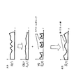
図5に示すように、本発明では、CELPコアレイヤからの合成信号スペクトル係数においてスペクトル包絡線の成形を行い、成形した合成信号を変換符号化レイヤのスペクトルギャップを埋める(満たす)ために使用する。
As shown in FIG. 5, in the present invention, the spectrum envelope is shaped with the synthesized signal spectrum coefficient from the CELP core layer, and the shaped synthesized signal is used to fill (fill) the spectrum gap of the transform coding layer.
スペクトル包絡線成形処理の詳細を以下に示す。
Details of the spectral envelope shaping process are shown below.
まず、音声符号化装置の処理を示す。(1)変換符号化レイヤの復号誤差信号スペクトル係数Se
~(f)を再構成する。(2)CELPコアレイヤからの合成信号スペクトル係数Ssyn(f)および以下の式に示すような変換符号化レイヤからの復号誤差信号スペクトル係数Se
~(f)を加算することによって復号信号スペクトル係数S~(f)を再構成する。

 (3)復号信号スペクトル係数S~(f)および入力信号スペクトル係数S(f)はともに複数のサブ帯域に分割される。(4)各サブ帯域ごとに、ゼロ復号誤差信号スペクトル係数Se
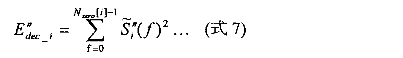
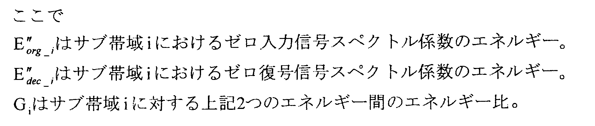
~(f)に対応する入力信号スペクトル係数S(f)のエネルギーを以下の式に示すように計算する。ここで、ゼロ復号誤差信号スペクトル係数とは、スペクトル係数値がゼロとなる復号誤差信号スペクトル係数を意味する。
(3)復号信号スペクトル係数S~(f)および入力信号スペクトル係数S(f)はともに複数のサブ帯域に分割される。(4)各サブ帯域ごとに、ゼロ復号誤差信号スペクトル係数Se
~(f)に対応する入力信号スペクトル係数S(f)のエネルギーを以下の式に示すように計算する。ここで、ゼロ復号誤差信号スペクトル係数とは、スペクトル係数値がゼロとなる復号誤差信号スペクトル係数を意味する。

 (5)各サブ帯域ごとに、ゼロ復号誤差信号スペクトル係数Se
~(f)に対応する復号信号スペクトル係数S~(f)のエネルギーを以下の式のように計算する。
(5)各サブ帯域ごとに、ゼロ復号誤差信号スペクトル係数Se
~(f)に対応する復号信号スペクトル係数S~(f)のエネルギーを以下の式のように計算する。

 (6)各サブ帯域ごとに、以下の式に示すようなエネルギー比を求める。

 (7)エネルギー比は量子化され音声復号化装置側に送信される。
First, the process of the speech coding apparatus is shown. (1) Reconstruct the decoding error signal spectral coefficients S e to (f) of the transform coding layer. (2) The decoded signal spectral coefficient by adding the synthesized signal spectral coefficient S syn (f) from the CELP core layer and the decoded error signal spectral coefficient S e to (f) from the transform coding layer as shown in the following equation: Reconstruct S ~ (f).
(7)エネルギー比は量子化され音声復号化装置側に送信される。
First, the process of the speech coding apparatus is shown. (1) Reconstruct the decoding error signal spectral coefficients S e to (f) of the transform coding layer. (2) The decoded signal spectral coefficient by adding the synthesized signal spectral coefficient S syn (f) from the CELP core layer and the decoded error signal spectral coefficient S e to (f) from the transform coding layer as shown in the following equation: Reconstruct S ~ (f).
(3) The decoded signal spectral coefficients S 1 to (f) and the input signal spectral coefficient S (f) are both divided into a plurality of subbands. (4) For each sub-band, the energy of the input signal spectral coefficient S (f) corresponding to the zero decoding error signal spectral coefficient S e to (f) is calculated as shown in the following equation. Here, the zero decoding error signal spectral coefficient means a decoding error signal spectral coefficient having a spectral coefficient value of zero.
(5) For each subband, the energy of the decoded signal spectral coefficients S 1 to (f) corresponding to the zero decoded error signal spectral coefficients S e to (f) is calculated as in the following equation.
(6) An energy ratio as shown in the following equation is obtained for each sub-band.
(7) The energy ratio is quantized and transmitted to the speech decoding apparatus side.
次に、音声復号化装置の処理を示す。(1)エネルギー比を逆量子化する。(2)CELPコアレイヤからの合成信号スペクトル係数を、復号エネルギー比から求めたスペクトル包絡線成形パラメータに従って成形する。(3)スペクトル包絡線成形スペクトルは、以下の式に示すように変換符号化レイヤのスペクトルギャップを埋めるために利用される。

 Next, processing of the speech decoding apparatus is shown. (1) Inversely quantize the energy ratio. (2) The synthesized signal spectrum coefficient from the CELP core layer is shaped according to the spectrum envelope shaping parameter obtained from the decoding energy ratio. (3) The spectrum envelope shaped spectrum is used to fill the spectrum gap of the transform coding layer as shown in the following equation.
本発明によれば、スペクトル中のスペクトルギャップを埋めることにより、復号信号中の鈍くこもった音を回避して音声品質の劣化を抑えることができる。
According to the present invention, by filling the spectrum gap in the spectrum, it is possible to avoid the dull sound in the decoded signal and suppress the deterioration of the voice quality.
以下、本発明の実施の形態について図面を参照して詳細に説明する。なお、各実施の形態において、同一の構成要素には同一の符号を付し、その説明は重複するので省略する。
Hereinafter, embodiments of the present invention will be described in detail with reference to the drawings. Note that, in each embodiment, the same components are denoted by the same reference numerals, and the description thereof is omitted because it is redundant.
(実施の形態1)
図6は本実施の形態に係る音声符号化装置の構成を示す図であり、図9は本実施の形態に係る音声復号化装置の構成を示す図である。図6および図9では、本発明をCELPおよび変換符号化の階層符号化(階層符号化、埋め込み符号化)に適用した場合を示す。 (Embodiment 1)
FIG. 6 is a diagram showing the configuration of the speech encoding apparatus according to the present embodiment, and FIG. 9 is a diagram showing the configuration of the speech decoding apparatus according to the present embodiment. FIGS. 6 and 9 show a case where the present invention is applied to CELP and hierarchical coding of transform coding (hierarchical coding and embedded coding).
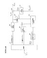
図6に示す音声符号化装置において、CELP符号化部601は、時間領域の信号の予測可能性を生かして符号化を行う。
In the speech encoding apparatus shown in FIG. 6, the CELP encoding unit 601 performs encoding utilizing the predictability of the time domain signal.
CELPローカル復号部602は、CELP符号化パラメータにより合成信号の再構成を行い、多重化部609は、CELP符号化パラメータを多重化し音声復号化装置に送信する。
CELP local decoding section 602 reconstructs the synthesized signal based on the CELP coding parameters, and multiplexing section 609 multiplexes the CELP coding parameters and transmits them to the speech decoding apparatus.
減算器610は、入力信号から合成信号を減算することにより誤差信号Se(n)(入力信号および合成信号間の差信号)を求める。
The subtractor 610 obtains an error signal S e (n) (difference signal between the input signal and the synthesized signal) by subtracting the synthesized signal from the input signal.
T/F変換部603および604は、合成信号および誤差信号Se(n)を、離散フーリエ変換(DFT)または変形離散コサイン変換(MDCT)などの時間領域から周波数領域への変換方法を用いて、合成信号スペクトル係数および誤差信号スペクトル係数Se(f)に変換する。
The T / F converters 603 and 604 convert the combined signal and the error signal S e (n) using a time domain to frequency domain conversion method such as discrete Fourier transform (DFT) or modified discrete cosine transform (MDCT). , Converted into a combined signal spectral coefficient and an error signal spectral coefficient S e (f).
ベクトル量子化部605は、誤差信号スペクトル係数Se(f)に対してベクトル量子化を実行し、ベクトル量子化パラメータを生成する。
The vector quantization unit 605 performs vector quantization on the error signal spectral coefficient S e (f) to generate a vector quantization parameter.
多重化部609は、ベクトル量子化パラメータを多重化し音声復号化装置に送信する。
The multiplexing unit 609 multiplexes the vector quantization parameter and transmits it to the speech decoding apparatus.
同時に、ベクトル逆量子化部606は、ベクトル量子化パラメータを逆量子化し復号誤差信号スペクトル係数Se
~(f)を再構成する。
At the same time, the vector inverse quantization unit 606 dequantizes the vector quantization parameter to reconstruct the decoded error signal spectrum coefficient S e ˜ (f).
スペクトル包絡線抽出部607は、スペクトル包絡線成形パラメータ{Gi}を合成信号スペクトル係数、誤差信号スペクトル係数および復号誤差信号スペクトル係数から抽出する。
The spectrum envelope extraction unit 607 extracts the spectrum envelope shaping parameter {G i } from the synthesized signal spectral coefficient, the error signal spectral coefficient, and the decoded error signal spectral coefficient.
量子化部608は、スペクトル包絡線成形パラメータ{Gi}を量子化し、多重化部609は、量子化パラメータを多重化し音声復号化装置に送信する。
The quantization unit 608 quantizes the spectrum envelope shaping parameter {G i }, and the multiplexing unit 609 multiplexes the quantization parameter and transmits it to the speech decoding apparatus.
図7にスペクトル包絡線抽出部607の詳細を示す。
FIG. 7 shows details of the spectrum envelope extraction unit 607.
図7に示すように、スペクトル包絡線抽出部607に対する入力は、合成信号スペクトル係数Ssyn(f)、誤差信号スペクトル係数 Se(f)および復号誤差信号スペクトル係数Se
~(f)である。出力はスペクトル包絡線成形パラメータ{Gi}である。
As shown in FIG. 7, the input to the spectral envelope extraction unit 607 is a combined signal spectral coefficient S syn (f), an error signal spectral coefficient S e (f), and decoded error signal spectral coefficients S e to (f). . The output is the spectral envelope shaping parameter {G i }.
まず、加算器708は、合成信号スペクトル係数Ssyn(f)および誤差信号スペクトル係数Se(f)を加算して入力信号スペクトル係数S(f)を成形する。また、加算器707は、合成信号スペクトル係数Ssyn(f)、復号誤差信号スペクトル係数Se
~(f)を加算して復号信号スペクトル係数S~(f)を形成する。
First, the adder 708 adds the combined signal spectral coefficient S syn (f) and the error signal spectral coefficient S e (f) to form the input signal spectral coefficient S (f). The adder 707 adds the combined signal spectral coefficient S syn (f) and the decoded error signal spectral coefficient S e to (f) to form a decoded signal spectral coefficient S 1 to (f).
次に、帯域分割部702および701は、入力信号スペクトル係数S(f) および復号信号スペクトル係数S~(f)を複数のサブ帯域に分割する。
Next, band division sections 702 and 701 divide input signal spectral coefficient S (f) and decoded signal spectral coefficient S 1- (f) into a plurality of subbands.
次に、スペクトル係数分割部704および703は、復号誤差信号スペクトル係数を参照し、入力信号スペクトル係数と復号信号スペクトル係数それぞれを2つの組に分類する。まず、入力信号スペクトル係数について説明する。スペクトル係数分割部704は、各サブ帯域において、復号信号スペクトル係数値がゼロである帯域に対応する入力信号スペクトル係数をゼロ入力信号スペクトル係数、復号信号スペクトル係数値がゼロでない帯域に対応する入力信号スペクトル係数を非ゼロ入力信号スペクトル係数というように2つのタイプに分類する。スペクトル係数分割部703は、復号誤差信号スペクトル係数に基づいた同様の分類を復号信号スペクトル係数にも適用し、ゼロ復号誤差信号スペクトル係数および非ゼロ復号信号スペクトル係数を求める。
Next, the spectral coefficient dividing units 704 and 703 refer to the decoded error signal spectral coefficients and classify each of the input signal spectral coefficients and the decoded signal spectral coefficients into two sets. First, the input signal spectrum coefficient will be described. Spectral coefficient division section 704, in each subband, input signal spectral coefficient corresponding to the band where the decoded signal spectral coefficient value is zero, zero input signal spectral coefficient, input signal corresponding to the band where the decoded signal spectral coefficient value is not zero Spectral coefficients are classified into two types as non-zero input signal spectral coefficients. Spectral coefficient division section 703 applies the same classification based on the decoded error signal spectral coefficient to the decoded signal spectral coefficient to obtain a zero decoded error signal spectral coefficient and a non-zero decoded signal spectral coefficient.
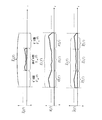
図8に示すように、スペクトル係数分割部704は、第iサブ帯域に対して、復号誤差スペクトル係数値がゼロである帯域(ゼロ復号誤差信号スペクトル係数)と復号誤差スペクトル係数値がゼロでない帯域(非ゼロ復号誤差信号スペクトル係数)に分割する。第iサブ帯域の入力信号スペクトル係数Si(f)をゼロ復号誤差信号スペクトル係数S”ei
~(f)と非ゼロ復号誤差信号スペクトル係数S’ei
~(f)に対応させて、ゼロ復号誤差信号スペクトル係数S”ei
~(f)が位置する帯域に含まれるスペクトル係数をゼロ入力信号スペクトル係数S”i(f)、非ゼロ復号誤差信号スペクトル係数S’ei
~(f)が位置する帯域に含まれるスペクトル係数を非ゼロ入力信号スペクトル係数S’i(f)とに分類する。同様に、スペクトル係数分割部703は、第iサブ帯域の復号信号スペクトル係数Si
~(f)を、ゼロ復号誤差信号スペクトル係数S”ei
~(f)と非ゼロ復号誤差信号スペクトル係数S’ei
~(f)に対応させて、ゼロ復号信号スペクトル係数S”i
~(f)と非ゼロ復号信号スペクトル係数S’i
~(f)とに分類する。
As illustrated in FIG. 8, the spectral coefficient dividing unit 704 performs, for the i-th subband, a band where the decoding error spectral coefficient value is zero (zero decoding error signal spectral coefficient) and a band where the decoding error spectral coefficient value is not zero. (Non-zero decoding error signal spectral coefficient). An input signal spectral coefficients S i of the i sub-band (f) in correspondence with the zero decoded error signal spectral coefficients S "ei ~ (f) non-zero decoded error signal spectral coefficients S 'ei ~ (f), the zero decode The spectrum coefficient included in the band where the error signal spectrum coefficient S ″ ei ˜ (f) is located is the zero input signal spectrum coefficient S ″ i (f), and the non-zero decoded error signal spectrum coefficient S ′ ei ˜ (f) is located. The spectral coefficients included in the band are classified as non-zero input signal spectral coefficients S ′ i (f) Similarly, the spectral coefficient dividing unit 703 converts the decoded signal spectral coefficients S i ˜ (f) of the i-th subband. The zero decoded signal spectral coefficient S ″ i ˜ (f) and the non-zero decoding error spectrum spectral coefficient S ″ ei ˜ (f) and the non-zero decoded error signal spectral coefficient S ′ ei ˜ (f) The signal spectrum coefficients are classified into S ′ i to (f).
サブ帯域エネルギー算出部706および705は、ゼロ入力信号スペクトル係数S”i(f) およびゼロ復号信号スペクトル係数S”i
~(f)において各サブ帯域ごとにエネルギーを計算し、以下の式に示すようにエネルギーを計算する。


 The sub-band
 energy calculation units 706 and 705 calculate energy for each sub-band in the zero input signal spectral coefficient S ″ i (f) and the zero decoded signal spectral coefficient S ″ i to (f). To calculate energy.
上記2つのエネルギー間の比は以下の式のように計算する。
The ratio between the above two energies is calculated as follows:

この{Gi}が除算器707からスペクトル包絡線成形パラメータとして出力される。
This {G i } is output from the divider 707 as a spectral envelope shaping parameter.
図9に示す音声復号化装置において、まず、分離部901は、すべてのビットストリーム情報を分離して、CELP符号化パラメータ、ベクトル量子化パラメータ及び量子化パラメータを生成し、それぞれCELP復号部902、ベクトル逆量子化部904および逆量子化部905に出力する。
In the speech decoding apparatus shown in FIG. 9, first, the separation unit 901 separates all bitstream information to generate CELP coding parameters, vector quantization parameters, and quantization parameters, respectively, CELP decoding unit 902, The result is output to vector inverse quantization section 904 and inverse quantization section 905.
CELP復号部902は、CELP符号化パラメータにより、合成信号Ssyn(n)を再構成する。
CELP decoding section 902 reconstructs synthesized signal S syn (n) based on the CELP coding parameters.
T/F変換部903は、合成信号Ssyn(n)を、離散フーリエ変換(DFT)または変形離散コサイン変換(MDCT)などの時間領域から周波数領域への変換方法を用いて復号信号スペクトル係数Ssyn(f)に変換する。
The T / F converter 903 uses the time domain to frequency domain conversion method such as discrete Fourier transform (DFT) or modified discrete cosine transform (MDCT) to convert the synthesized signal S syn (n) into a decoded signal spectral coefficient S. Convert to syn (f).
ベクトル逆量子化部904は、ベクトル量子化パラメータを逆量子化して復号誤差信号スペクトル係数Se
~(f)を再構成する。
The vector inverse quantization unit 904 dequantizes the vector quantization parameter to reconstruct the decoded error signal spectral coefficients S e to (f).
逆量子化部905は、スペクトル包絡線成形パラメータ用の量子化パラメータを逆量子化して復号スペクトル包絡線成形パラメータ{Gi
~}を再構成する。
The inverse quantization unit 905 requantizes the quantization parameter for the spectrum envelope shaping parameter to reconstruct the decoded spectrum envelope shaping parameter {G i ˜ }.
スペクトル包絡線成形部906は、復号スペクトル包絡線成形パラメータ{Gi
~}、合成信号スペクトル係数Ssyn(f)および復号誤差信号スペクトル係数Se
~(f)により、復号誤差信号スペクトル係数のスペクトルギャップを埋めて、後処理誤差信号スペクトル係数Spost_e
~(f)を生成する。
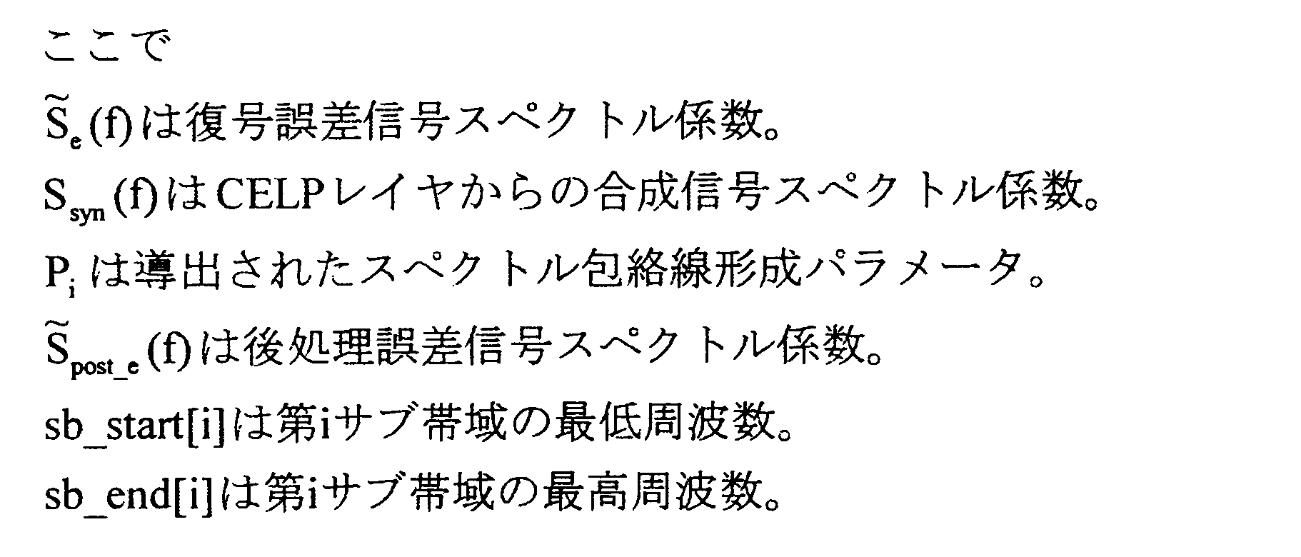
The spectrum envelope shaping unit 906 calculates the spectrum of the decoded error signal spectral coefficient based on the decoded spectral envelope shaping parameter {G i ~ }, the synthesized signal spectral coefficient S syn (f), and the decoded error signal spectral coefficient S e ~ (f). The post-processing error signal spectral coefficient S post_e ˜ (f) is generated by filling the gap.
F/T変換部907は、後処理誤差信号スペクトル係数Spost_e
~(f)を時間領域に再変換し、逆離散フーリエ変換(IDFT)または逆変形離散コサイン変換(IMDCT)などの周波数領域から時間領域への変換方法を用いて復号誤差信号Se
~(n)を再構成する。
The F / T conversion unit 907 reconverts the post-processing error signal spectral coefficient S post_e to (f) into the time domain, and performs time conversion from the frequency domain such as inverse discrete Fourier transform (IDFT) or inverse modified discrete cosine transform (IMDCT). The decoding error signal S e ˜ (n) is reconstructed using the method of converting to a region.
加算器908は、合成信号Ssyn(n)および復号誤差信号Se
~(n)を加算することによって復号信号S~(n)を再構成する。
The adder 908, to reconstruct the decoded signal S ~ (n) by adding the composite signal S syn (n) and the decoded error signal S e ~ a (n).
図10にスペクトル包絡線成形部906の詳細を示す。
FIG. 10 shows the details of the spectrum envelope forming unit 906.
図10に示すように、スペクトル包絡線成形部906に対する入力は、復号スペクトル包絡線成形パラメータ{Gi
~}、合成信号スペクトル係数Ssyn(f) および復号誤差信号スペクトル係数Se
~(f)である。出力は後処理誤差信号スペクトル係数Spost_e
~(f)である。
As shown in FIG. 10, the input to the spectral envelope shaping unit 906 includes the decoded spectral envelope shaping parameter {G i ~ }, the synthesized signal spectral coefficient S syn (f), and the decoded error signal spectral coefficient S e ~ (f). It is. The output is the post-processing error signal spectral coefficient S post — e˜ (f).
帯域分割部1001は、合成信号スペクトル係数Ssyn(f)を複数のサブ帯域に分割する。
Band division section 1001 divides synthesized signal spectrum coefficient S syn (f) into a plurality of sub-bands.
次に、スペクトル係数分割部1002は、図8に示すように、復号誤差信号スペクトル係数を参照し、合成信号スペクトル係数を2つの組に分類する。つまり、スペクトル係数分割部1002は、各サブ帯域において、復号信号スペクトル係数値がゼロである帯域に対応する合成信号スペクトル係数をゼロ合成信号スペクトル係数S”syn_i(f)、復号信号スペクトル係数値がゼロでない帯域に対応する合成信号スペクトル係数を非ゼロ合成信号スペクトル係数S’syn_i(f)というように2つのタイプに分類する。
Next, as shown in FIG. 8, the spectral coefficient dividing unit 1002 refers to the decoded error signal spectral coefficients and classifies the combined signal spectral coefficients into two sets. That is, in each subband, the spectral coefficient dividing unit 1002 generates a combined signal spectral coefficient corresponding to a band where the decoded signal spectral coefficient value is zero, a zero combined signal spectral coefficient S ” syn_i (f), and the decoded signal spectral coefficient value is The synthesized signal spectrum coefficient corresponding to the non-zero band is classified into two types as non-zero synthesized signal spectrum coefficient S ′ syn — i (f).
スペクトル包絡線成形パラメータ生成部1003は、復号スペクトル包絡線成形パラメータGi
~を処理して、適切なスペクトル包絡線成形パラメータを計算する。その方法の1つを以下の式に示す。

 The spectrum envelope shaping
 parameter generation unit 1003 processes the decoded spectrum envelope shaping parameters G i to calculate appropriate spectrum envelope shaping parameters. One such method is shown in the following equation.
そして、次式に示されるように、乗算器1004によってCELPレイヤからの合成信号スペクトル係数はスペクトル包絡線成形パラメータに従って成形され、加算器1005によって後処理誤差信号スペクトルが生成される。


 Then, as shown in the following equation, the synthesized signal spectrum coefficient from the CELP layer is shaped according to the spectrum envelope shaping parameter by the multiplier 1004, and the post-processing error signal spectrum is generated by the
 adder 1005.
<バリエーション>
符号化部においては、ゼロ入力信号スペクトル係数、ゼロ復号信号スペクトル係数の少なくとも一方が分類された後、復号部においてはゼロ合成信号スペクトル係数が分類された後に、これら分類結果を考慮して帯域分割を行っても良い。これにより、効率的にサブ帯域を決定することが可能となる。 <Variation>
The encoding unit classifies at least one of the zero input signal spectral coefficient and the zero decoded signal spectral coefficient, and after classifying the zero synthesized signal spectral coefficient in the decoding unit, the band division is performed in consideration of the classification result. May be performed. Thereby, it becomes possible to determine a sub-band efficiently.
スペクトル包絡線成形パラメータの量子化に利用できるビット数がフレームごとに可変となる構成に本発明を適用しても良い。これは例えば、可変ビットレート符号化方式、または図6におけるベクトル量子化部605での量子化ビット数がフレーム毎に変動するような方式が用いられている場合が該当する。その場合、スペクトル包絡線成形パラメータの量子化に利用可能なビット数の大きさに従って帯域分割を行っても良い。例えば、利用可能ビット数が多い場合、サブ帯域数が多くなるように帯域分割を行うことでスペクトル包絡線形成パラメータをより多く量子化することができる(高い解像度の実現)。逆に利用可能ビット数が少ない場合、サブ帯域数が少なくなるように帯域分割を行うことでスペクトル包絡線形成パラメータをより少なく量子化する(低い解像度の実現)。このように利用できるビット数に応じてサブ帯域数を適応的に変化させることにより、利用できるビット数に適した数のスペクトル包絡線形成パラメータの量子化を実現でき、音質改善を図ることができる。
The present invention may be applied to a configuration in which the number of bits that can be used for quantization of the spectral envelope shaping parameter is variable for each frame. This corresponds to, for example, a case where a variable bit rate encoding method or a method in which the number of quantization bits in the vector quantization unit 605 in FIG. 6 varies from frame to frame is used. In that case, band division may be performed according to the number of bits available for quantization of the spectral envelope shaping parameter. For example, when the number of available bits is large, more spectrum envelope forming parameters can be quantized by performing band division so as to increase the number of subbands (realization of high resolution). On the other hand, when the number of available bits is small, the spectral envelope forming parameters are quantized less by performing band division so that the number of subbands is small (realization of low resolution). By adaptively changing the number of subbands according to the number of bits that can be used in this way, it is possible to realize the quantization of the number of spectrum envelope forming parameters suitable for the number of bits that can be used, and to improve sound quality. .
スペクトル包絡線形成パラメータの量子化を行う際、高周波数帯域から低周波数帯域の順に量子化を行っても良い。この理由は、低周波数帯域においてCELPは線形予測モデル化により音声信号を非常に効率良く符号化ができる。そのため、CELPをコアレイヤに用いた場合、高周波数帯域のスペクトルギャップを埋める方が聴感上より重要になるためである。
Quantization of spectral envelope forming parameters may be performed in order from the high frequency band to the low frequency band. This is because CELP can encode a speech signal very efficiently by linear prediction modeling in a low frequency band. Therefore, when CELP is used for the core layer, it is more important for hearing to fill the spectrum gap in the high frequency band.
スペクトル包絡線形成パラメータの量子化に用いることのできるビット数が不足する場合、大きなGi値(Gi>1)もしくは小さなGi値(Gi<1)を持つスペクトル包絡線形成パラメータを選択し、選択されたスペクトル包絡線形成パラメータに限定して量子化を行い復号器側に送信しても良い。つまりこれは、ゼロ入力信号スペクトル係数のエネルギーとゼロ復号信号スペクトル係数のエネルギーの違いが大きいサブ帯域に限定してスペクトル包絡線形成パラメータを量子化することを意味している。これにより、聴感的に改善度の大きいサブ帯域の情報を選択して量子化することになるため、音質改善を実現できる。なおこの場合、選択されたエネルギーのサブ帯域を示すためのフラグを送信する。
If the number of bits that can be used to quantize the spectral envelope forming parameter is insufficient, select a spectral envelope forming parameter with a large Gi value (G i > 1) or a small Gi value (G i <1), The quantization may be limited to the selected spectral envelope forming parameter and transmitted to the decoder side. That is, this means that the spectral envelope forming parameters are quantized only in the sub-band where the energy difference between the zero input signal spectral coefficient and the zero decoded signal spectral coefficient is large. As a result, the sub-band information having a large degree of improvement in perception is selected and quantized, so that the sound quality can be improved. In this case, a flag for indicating the subband of the selected energy is transmitted.
スペクトル包絡線形成パラメータの量子化の際、量子化後に復号されたスペクトル包絡線形成パラメータが、量子化の対象となるスペクトル包絡線形成パラメータの値を越えないように制限を設けて量子化を行っても良い。これにより、スペクトルギャップを埋める後処理誤差信号スペクトル係数が不必要に大きくなることを避けることができ、音質を改善することができる。
When quantizing the spectral envelope forming parameters, quantization is performed with a restriction so that the spectral envelope forming parameters decoded after quantization do not exceed the value of the spectral envelope forming parameter to be quantized. May be. Thereby, it is possible to avoid an unnecessarily large post-processing error signal spectrum coefficient filling the spectrum gap, and to improve sound quality.
(実施の形態2)
低ビットレートで符号化する構成の場合、スペクトルギャップが生じていない帯域(つまり変換符号化レイヤで符号化が行われた帯域)でも符号化精度が十分ではなく、入力信号スペクトル係数との符号化誤差が大きい場合がある。このような状態において、スペクトルギャップが生じていない帯域に対してもスペクトルギャップが生じている帯域と同様に、スペクトル包絡線成形を適用することで音質を改善することが可能である。また、この場合、スペクトルギャップが生じている帯域とは別にスペクトルギャップが生じていない帯域に対してスペクトル包絡線成形を実行した方が、大きな音質改善効果が得られる。 (Embodiment 2)
In the case of a configuration in which encoding is performed at a low bit rate, encoding accuracy is not sufficient even in a band in which a spectrum gap is not generated (that is, a band encoded in the transform coding layer), and encoding with input signal spectral coefficients is performed. The error may be large. In such a state, it is possible to improve sound quality by applying spectral envelope shaping to a band where a spectral gap is not generated, similarly to a band where a spectral gap is generated. Also, in this case, a greater sound quality improvement effect can be obtained by performing spectrum envelope shaping on a band in which a spectral gap is not generated separately from a band in which a spectral gap is generated.
本実施の形態に係るスペクトル包絡線抽出部の構成を図11に示す。図7との違いは、サブ帯域エネルギー算出部1108および1107が、非ゼロ入力信号スペクトル係数および非ゼロ復号信号スペクトル係数に対しても、エネルギー算出を行い、除算器1109が、ここで算出されるエネルギー比も併せてスペクトル包絡線成形パラメータとして出力する点にある。
FIG. 11 shows the configuration of the spectrum envelope extraction unit according to the present embodiment. The difference from FIG. 7 is that subband energy calculation sections 1108 and 1107 also calculate energy for non-zero input signal spectral coefficients and non-zero decoded signal spectral coefficients, and divider 1109 is calculated here. The energy ratio is also output as a spectral envelope shaping parameter.
本実施の形態のスペクトル包絡線成形部の構成を図12に示す。図10との違いは、スペクトルギャップが生じていない帯域用のスペクトル包絡線成形パラメータも併せて復号し、これも用いて後処理誤差信号スペクトル係数を生成する点にある。
FIG. 12 shows the configuration of the spectral envelope shaping unit of the present embodiment. The difference from FIG. 10 is that a spectral envelope shaping parameter for a band where no spectral gap is generated is also decoded and used to generate a post-processing error signal spectral coefficient.
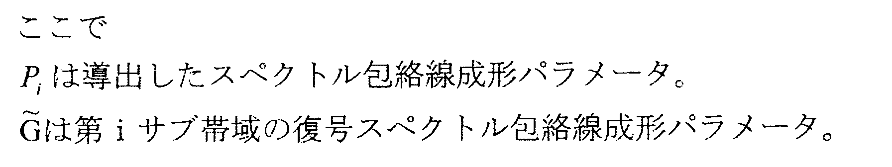
図12に示すように、スペクトル包絡線成形パラメータ生成部1203は、スペクトルギャップが生じていない帯域用の復号スペクトル包絡線成形パラメータG’i~を処理して適切な成形パラメータを計算する。その1つの方法を以下の式に示す。

 As shown in FIG. 12, the spectrum envelope shaping
 parameter generation unit 1203 processes the decoded spectrum envelope shaping parameter G ′ i for a band in which no spectrum gap is generated, and calculates an appropriate shaping parameter. One method is shown in the following equation.
加算器1204は、合成信号スペクトル係数を復号誤差信号スペクトル係数に加算して以下の式に示すように復号信号スペクトル係数を形成する。


Adder 1204 adds the combined signal spectral coefficient to the decoded error signal spectral coefficient to form a decoded signal spectral coefficient as shown in the following equation.
次式に示されるように、帯域分割部1001、スペクトル係数分割部1002、乗算器1004-1および1004-2、加算器1005-1および1005-2によって、復号信号スペクトル係数はスペクトル包絡線成形パラメータに従って各サブ帯域毎に成形され、後処理誤差信号スペクトルが生成される。


 As shown in the following equation, the
 band division unit 1001, the spectral coefficient division unit 1002, the multipliers 1004-1 and 1004-2, and the adders 1005-1 and 1005-2, the decoded signal spectral coefficients are converted into spectral envelope shaping parameters. Are formed for each sub-band, and a post-processing error signal spectrum is generated.
<バリエーション>
低ビットレートの構成の場合、全帯域においてスペクトルギャップが生じていない帯域全体に適用されるスペクトル包絡線成形パラメータを送信するようにしても良い。このときのスペクトル包絡線成形パラメータは以下の式に示すように計算することができる。

 <Variation>
In the case of a low bit rate configuration, a spectrum envelope shaping parameter applied to the entire band where no spectrum gap is generated in the entire band may be transmitted. The spectrum envelope shaping parameter at this time can be calculated as shown in the following equation.
低ビットレートの構成の場合、全帯域においてスペクトルギャップが生じていない帯域全体に適用されるスペクトル包絡線成形パラメータを送信するようにしても良い。このときのスペクトル包絡線成形パラメータは以下の式に示すように計算することができる。
In the case of a low bit rate configuration, a spectrum envelope shaping parameter applied to the entire band where no spectrum gap is generated in the entire band may be transmitted. The spectrum envelope shaping parameter at this time can be calculated as shown in the following equation.
音声復号化装置において、スペクトル包絡線成形パラメータは以下の式のように用いられる。

 In the speech decoding apparatus, the spectrum envelope shaping parameter is used as in the following equation.
(実施の形態3)
入力信号の音質を保持するために重要なことの一つに、異なる周波数帯域間のエネルギーバランスが保持されていることが挙げられる。従って、入力信号と同様となるように、復号信号においてスペクトルギャップのある帯域とそうでない帯域間のエネルギーバランスを維持することは非常に重要であり、ここでは、スペクトルギャップのある帯域とそうでない帯域間のエネルギーバランスを維持することのできる実施の形態について説明する。 (Embodiment 3)
One important factor for maintaining the sound quality of the input signal is that the energy balance between different frequency bands is maintained. Therefore, it is very important to maintain the energy balance between the band with and without the spectrum gap in the decoded signal so that it is the same as the input signal. An embodiment capable of maintaining the energy balance will be described.
図13は本実施の形態におけるスペクトル包絡線抽出部の構成を示す図である。図13に示すように、全帯域エネルギー算出部1308および1307が、非ゼロ入力信号スペクトル係数のエネルギーE’org、非ゼロ復号信号スペクトル係数のエネルギーE’decを計算する。エネルギー計算方法の一例を以下の式に示す。
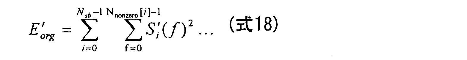

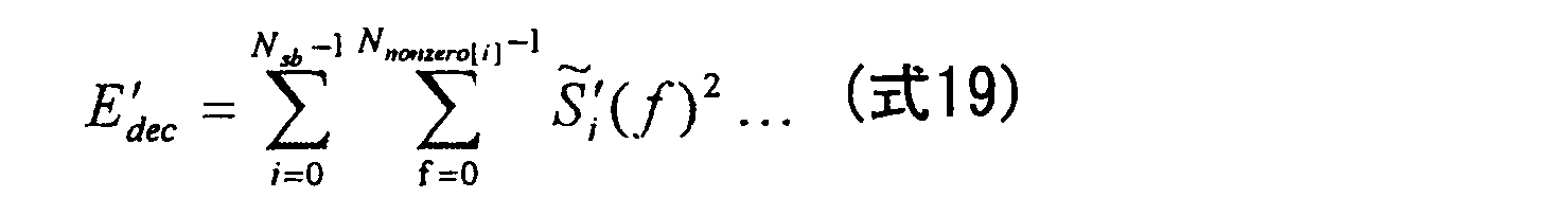
 FIG. 13 is a diagram showing the configuration of the spectrum envelope extraction unit in the present embodiment. As shown in FIG. 13, full-band
 energy calculation units 1308 and 1307 calculate non-zero input signal spectral coefficient energy E ′ org and non-zero decoded signal spectral coefficient energy E ′ dec . An example of the energy calculation method is shown in the following formula.
エネルギー比算出部1310および1309は、入力信号スペクトル係数に対するエネルギー比及び復号信号スペクトル係数に対するエネルギー比を以下の式に従ってそれぞれ計算する。


 The
The energy ratio calculators 1310 and 1309 calculate the energy ratio with respect to the input signal spectrum coefficient and the energy ratio with respect to the decoded signal spectrum coefficient, respectively, according to the following equations.
除算器707では、スペクトル包絡線成形パラメータが次式のように算出される。

 In the
 divider 707, the spectral envelope shaping parameter is calculated as follows:
(実施の形態4)
低ビットレートで符号化する構成の場合、スペクトルギャップが生じていない帯域(つまり変換符号化レイヤで符号化が行われた帯域)でも符号化精度が十分ではなく、入力信号スペクトル係数との符号化誤差が大きい場合がある。このような状態において、スペクトルギャップが生じていない帯域に対してもスペクトルギャップが生じている帯域と同様に、スペクトル包絡線成形を適用することで音質を改善することが可能である。本実施の形態は、実施の形態3にこの考えを適用したものである。 (Embodiment 4)
In the case of a configuration in which encoding is performed at a low bit rate, encoding accuracy is not sufficient even in a band in which a spectrum gap is not generated (that is, a band encoded in the transform coding layer), and encoding with input signal spectral coefficients is performed. The error may be large. In such a state, it is possible to improve sound quality by applying spectral envelope shaping to a band where a spectral gap is not generated, similarly to a band where a spectral gap is generated. In the present embodiment, this idea is applied to the third embodiment.
図14は本実施の形態におけるスペクトル包絡線抽出部の構成を示す図である。図14に示すように、エネルギー比算出部1411は、非ゼロ復号信号スペクトル係数のエネルギー E’decに対する非ゼロ入力信号スペクトル係数のエネルギー E’orgのエネルギー比をG’として求める。ここで算出されるエネルギー比G’も併せてスペクトル包絡線成形パラメータとして出力される。
FIG. 14 is a diagram showing a configuration of the spectrum envelope extraction unit in the present embodiment. As illustrated in FIG. 14, the energy ratio calculation unit 1411 obtains the energy ratio of the energy E ′ org of the non-zero input signal spectral coefficient to the energy E ′ dec of the non-zero decoded signal spectral coefficient as G ′. The energy ratio G ′ calculated here is also output as a spectrum envelope shaping parameter.
図15は本実施の形態におけるスペクトル包絡線成形部の構成を示す図である。スペクトル包絡線成形パラメータ生成部1503は、スペクトルギャップが生じていない帯域用のスペクトル包絡線成形パラメータを次の式のようにして計算する。

 FIG. 15 is a diagram showing a configuration of a spectrum envelope shaping unit in the present embodiment. The spectrum envelope shaping
 parameter generation unit 1503 calculates a spectrum envelope shaping parameter for a band in which no spectrum gap is generated as in the following equation.
以上、本発明の実施の形態1~4について説明した。
The first to fourth embodiments of the present invention have been described above.
なお、上記実施の形態では、装置を音声符号化装置/音声復号化装置と称したが、ここでの「音声」とは、広義の意味での音声を示すものである。すなわち、音声符号化装置における入力信号及び音声復号化装置における復号信号は、音声信号、音楽信号、あるいはこれら双方を含む音響信号、など、いずれの信号をも示すものである。
In the above embodiment, the device is referred to as a speech encoding device / speech decoding device, but “speech” here indicates speech in a broad sense. That is, the input signal in the speech encoding device and the decoded signal in the speech decoding device indicate both signals such as speech signals, music signals, or acoustic signals including both.
また、上記実施の形態では、本発明をハードウェアで構成する場合を例にとって説明したが、本発明はハードウェアとの連携においてソフトウェアでも実現することも可能である。
Further, although cases have been described with the above embodiment as examples where the present invention is configured by hardware, the present invention can also be realized by software in cooperation with hardware.
また、上記実施の形態の説明に用いた各機能ブロックは、典型的には集積回路であるLSIとして実現される。これらは個別に1チップ化されてもよいし、一部又は全てを含むように1チップ化されてもよい。ここでは、LSIとしたが、集積度の違いにより、IC、システムLSI、スーパーLSI、ウルトラLSIと呼称されることもある。
Further, each functional block used in the description of the above embodiment is typically realized as an LSI which is an integrated circuit. These may be individually made into one chip, or may be made into one chip so as to include a part or all of them. Although referred to as LSI here, it may be referred to as IC, system LSI, super LSI, or ultra LSI depending on the degree of integration.
また、集積回路化の手法はLSIに限るものではなく、専用回路又は汎用プロセッサで実現してもよい。LSI製造後に、プログラムすることが可能なFPGA(Field Programmable Gate Array)、または、LSI内部の回路セルの接続または設定を再構成可能なリコンフィギュラブルプロセッサーを利用してもよい。
Also, the method of circuit integration is not limited to LSI, and may be realized by a dedicated circuit or a general-purpose processor. An FPGA (Field Programmable Gate Array) that can be programmed after manufacturing the LSI or a reconfigurable processor that can reconfigure the connection or setting of circuit cells inside the LSI may be used.
さらには、半導体技術の進歩又は派生する別技術によりLSIに置き換わる集積回路化の技術が登場すれば、当然、その技術を用いて機能ブロックの集積化を行ってもよい。バイオ技術の適用等が可能性としてありえる。
Furthermore, if integrated circuit technology that replaces LSI emerges as a result of advances in semiconductor technology or other derived technology, it is naturally also possible to integrate functional blocks using this technology. Biotechnology can be applied.
2010年10月18日出願の特願2010-234088の日本出願に含まれる明細書、図面および要約書の開示内容は、すべて本願に援用される。
The disclosure of the specification, drawings and abstract contained in the Japanese application of Japanese Patent Application No. 2010-234088 filed on Oct. 18, 2010 is incorporated herein by reference.
本発明は、移動通信システムにおける無線通信端末装置、基地局装置、電話会議端末装置、ビデオ会議端末装置、インターネットプロトコル上での音声通信(VOIP)端末装置等に適用できる。
The present invention can be applied to a wireless communication terminal device, a base station device, a telephone conference terminal device, a video conference terminal device, a voice communication (VOIP) terminal device over the Internet protocol, etc. in a mobile communication system.
601 CELP符号化部
602 CELPローカル復号部
603,604 T/F変換部
605 ベクトル量子化部
606 ベクトル逆量子化部
607 ベクトル包絡線抽出部
608 量子化部
609 多重化部
901 分離部
902 CELP復号部
903 T/F変換部
904 ベクトル逆量子化部
905 逆量子化部
906 スペクトル包絡線成形部
907 F/T変換部
908 加算器 601CELP encoding unit 602 CELP local decoding unit 603, 604 T / F conversion unit 605 vector quantization unit 606 vector inverse quantization unit 607 vector envelope extraction unit 608 quantization unit 609 multiplexing unit 901 separation unit 902 CELP decoding unit 903 T / F conversion unit 904 Vector inverse quantization unit 905 Inverse quantization unit 906 Spectrum envelope shaping unit 907 F / T conversion unit 908 Adder
602 CELPローカル復号部
603,604 T/F変換部
605 ベクトル量子化部
606 ベクトル逆量子化部
607 ベクトル包絡線抽出部
608 量子化部
609 多重化部
901 分離部
902 CELP復号部
903 T/F変換部
904 ベクトル逆量子化部
905 逆量子化部
906 スペクトル包絡線成形部
907 F/T変換部
908 加算器 601
Claims (20)
- 入力信号を符号化して第1符号化データを生成する第1符号化部と、
前記第1符号化データを復号して第1復号信号を生成する第1ローカル復号部と、
前記入力信号から前記第1復号信号を減算して誤差信号を生成する減算部と、
前記誤差信号のスペクトル係数の一部のみを符号化して第2符号化データを生成する第2符号化部と、
スペクトル包絡線成形パラメータを計算するスペクトル包絡線成形パラメータ計算部と、
前記スペクトル包絡線成形パラメータを量子化して第3符号化データを生成する量子化部と、
を具備する音声符号化装置。 A first encoding unit that encodes an input signal to generate first encoded data;
A first local decoding unit that decodes the first encoded data to generate a first decoded signal;
A subtractor for subtracting the first decoded signal from the input signal to generate an error signal;
A second encoding unit that encodes only a part of the spectral coefficient of the error signal to generate second encoded data;
A spectral envelope shaping parameter calculation unit for calculating a spectral envelope shaping parameter;
A quantization unit that quantizes the spectral envelope shaping parameter to generate third encoded data;
A speech encoding apparatus comprising: - 前記スペクトル包絡線成形パラメータ計算部は、
前記第2符号化データからゼロ復号誤差信号スペクトル係数と非ゼロ復号誤差信号スペクトル係数より成る復号誤差信号スペクトル係数を生成する第2ローカル復号部と、
前記第1復号信号のスペクトル係数と前記復号誤差信号スペクトル係数とを加算して復号信号スペクトル係数を生成する加算部と、
前記入力信号のスペクトル係数の入力信号エネルギーを計算する第1エネルギー計算部と、
前記復号信号スペクトル係数の復号信号エネルギーを計算する第2エネルギー計算部と、
前記入力信号エネルギーと前記復号信号エネルギーとの間のエネルギー比を計算するエネルギー比計算部と、
を具備する請求項1に記載の音声符号化装置。 The spectral envelope shaping parameter calculation unit,
A second local decoding unit for generating a decoding error signal spectral coefficient comprising a zero decoding error signal spectral coefficient and a non-zero decoding error signal spectral coefficient from the second encoded data;
An adder for adding a spectral coefficient of the first decoded signal and the decoded error signal spectral coefficient to generate a decoded signal spectral coefficient;
A first energy calculator for calculating an input signal energy of a spectral coefficient of the input signal;
A second energy calculation unit for calculating decoded signal energy of the decoded signal spectral coefficient;
An energy ratio calculator for calculating an energy ratio between the input signal energy and the decoded signal energy;
The speech encoding apparatus according to claim 1, comprising: - 前記スペクトル包絡線成形パラメータ計算部は、
前記第2符号化データからゼロ復号誤差信号スペクトル係数と非ゼロ復号誤差信号スペクトル係数より成る復号誤差信号スペクトル係数を生成する第2ローカル復号部と、
前記第1復号信号のスペクトル係数と前記復号誤差信号スペクトル係数とを加算して復号信号スペクトル係数を生成する加算部と、
前記ゼロ復号誤差信号スペクトル係数に対応する、前記入力信号のスペクトル係数の入力信号エネルギーを計算する第1エネルギー計算部と、
前記ゼロ復号誤差信号スペクトル係数に対応する、前記復号信号スペクトル係数の復号信号エネルギーを計算する第2エネルギー計算部と、
前記入力信号エネルギーと前記復号信号エネルギーとの間のエネルギー比を計算するエネルギー比計算部と、
を具備する請求項1に記載の音声符号化装置。 The spectral envelope shaping parameter calculation unit,
A second local decoding unit for generating a decoding error signal spectral coefficient comprising a zero decoding error signal spectral coefficient and a non-zero decoding error signal spectral coefficient from the second encoded data;
An adder for adding a spectral coefficient of the first decoded signal and the decoded error signal spectral coefficient to generate a decoded signal spectral coefficient;
A first energy calculator that calculates an input signal energy of a spectral coefficient of the input signal corresponding to the zero decoding error signal spectral coefficient;
A second energy calculator that calculates a decoded signal energy of the decoded signal spectral coefficient corresponding to the zero decoded error signal spectral coefficient;
An energy ratio calculator for calculating an energy ratio between the input signal energy and the decoded signal energy;
The speech encoding apparatus according to claim 1, comprising: - 前記スペクトル包絡線成形パラメータ計算部は、
前記第2符号化データからゼロ復号誤差信号スペクトル係数と非ゼロ復号誤差信号スペクトル係数より成る復号誤差信号スペクトル係数を生成する第2ローカル復号部と、
前記第1復号信号のスペクトル係数と前記復号誤差信号スペクトル係数とを加算して復号信号スペクトル係数を生成する加算部と、
前記非ゼロ復号誤差信号スペクトル係数に対応する、前記入力信号のスペクトル係数の入力信号エネルギーを計算する第1エネルギー計算部と、
前記非ゼロ復号誤差信号スペクトル係数に対応する、前記復号信号スペクトル係数の復号信号エネルギーを計算する第2エネルギー計算部と、
を具備する請求項1に記載の音声符号化装置。 The spectral envelope shaping parameter calculation unit,
A second local decoding unit for generating a decoding error signal spectral coefficient comprising a zero decoding error signal spectral coefficient and a non-zero decoding error signal spectral coefficient from the second encoded data;
An adder for adding a spectral coefficient of the first decoded signal and the decoded error signal spectral coefficient to generate a decoded signal spectral coefficient;
A first energy calculator that calculates an input signal energy of a spectral coefficient of the input signal corresponding to the non-zero decoding error signal spectral coefficient;
A second energy calculator that calculates a decoded signal energy of the decoded signal spectral coefficient corresponding to the non-zero decoded error signal spectral coefficient;
The speech encoding apparatus according to claim 1, comprising: - 前記スペクトル包絡線成形パラメータ計算部は、
前記第2符号化データからゼロ復号誤差信号スペクトル係数と非ゼロ復号誤差信号スペクトル係数より成る復号誤差信号スペクトル係数を生成する第2ローカル復号部と、
前記第1復号信号のスペクトル係数と前記復号誤差信号スペクトル係数とを加算して復号信号スペクトル係数を生成する加算部と、
前記非ゼロ復号誤差信号スペクトル係数に対応する、入力信号のスペクトル係数の第1入力信号エネルギーを計算する第1エネルギー計算部と、
前記非ゼロ復号誤差信号スペクトル係数に対応する、前記復号信号スペクトル係数の第1復号信号エネルギーを計算する第2エネルギー計算部と、
前記非ゼロ復号誤差信号スペクトル係数に対応する前記第1入力信号エネルギーと前記非ゼロ復号誤差信号スペクトル係数に対応する前記第1復号信号エネルギーとの間の第1エネルギー比を計算する第1エネルギー比計算部と、
前記ゼロ復号誤差信号スペクトル係数に対応する、入力信号のスペクトル係数の第2入力信号エネルギーを計算する第3エネルギー計算部と、
前記ゼロ復号誤差信号スペクトル係数に対応する、前記復号信号スペクトル係数の第2復号信号エネルギーを計算する第4エネルギー計算部と、
前記第2入力信号エネルギーと前記第2復号信号エネルギーとの間の第2エネルギー比を計算する第2エネルギー比計算部と、
を具備する請求項1に記載の音声符号化装置。 The spectral envelope shaping parameter calculation unit,
A second local decoding unit for generating a decoding error signal spectral coefficient comprising a zero decoding error signal spectral coefficient and a non-zero decoding error signal spectral coefficient from the second encoded data;
An adder for adding a spectral coefficient of the first decoded signal and the decoded error signal spectral coefficient to generate a decoded signal spectral coefficient;
A first energy calculator that calculates a first input signal energy of a spectral coefficient of an input signal corresponding to the non-zero decoding error signal spectral coefficient;
A second energy calculator that calculates a first decoded signal energy of the decoded signal spectral coefficient corresponding to the non-zero decoded error signal spectral coefficient;
A first energy ratio that calculates a first energy ratio between the first input signal energy corresponding to the non-zero decoded error signal spectral coefficient and the first decoded signal energy corresponding to the non-zero decoded error signal spectral coefficient; A calculation unit;
A third energy calculator for calculating a second input signal energy of a spectral coefficient of the input signal corresponding to the zero decoding error signal spectral coefficient;
A fourth energy calculator that calculates a second decoded signal energy of the decoded signal spectral coefficient corresponding to the zero decoded error signal spectral coefficient;
A second energy ratio calculator for calculating a second energy ratio between the second input signal energy and the second decoded signal energy;
The speech encoding apparatus according to claim 1, comprising: - 前記スペクトル包絡線成形パラメータ計算部は、
前記第2エネルギー比と前記第1エネルギー比との間の比を計算する比計算部、をさらに具備する、
請求項5に記載の音声符号化装置。 The spectral envelope shaping parameter calculation unit,
A ratio calculator that calculates a ratio between the second energy ratio and the first energy ratio;
The speech encoding apparatus according to claim 5. - 前記第1符号化部は、符号励振線形予測を用いて前記入力信号を符号化する、
請求項1に記載の音声符号化装置。 The first encoding unit encodes the input signal using code-excited linear prediction;
The speech encoding apparatus according to claim 1. - 前記第2符号化部は、ベクトル量子化を用いて、前記誤差信号のスペクトル係数の一部のみを符号化する、
請求項1に記載の音声符号化装置。 The second encoding unit encodes only a part of the spectrum coefficient of the error signal using vector quantization.
The speech encoding apparatus according to claim 1. - 前記第2符号化部は、限定された数のパルスで前記スペクトル係数を表現する前記ベクトル量子化を行う、
請求項8に記載の音声符号化装置。 The second encoding unit performs the vector quantization that represents the spectral coefficient with a limited number of pulses.
The speech encoding apparatus according to claim 8. - 前記スペクトル係数を複数のサブ帯域に分割する帯域分割を行う帯域分割部と、
前記複数のサブ帯域のうちスペクトル包絡線成形を必要とする一部のサブ帯域を決定する帯域決定部と、をさらに具備し、
前記スペクトル包絡線成形パラメータ計算部は、前記一部のサブ帯域に対する前記スペクトル包絡線成形パラメータを計算する、
請求項1に記載の音声符号化装置。 A band dividing unit that performs band division to divide the spectral coefficient into a plurality of sub-bands;
A band determination unit that determines a part of the plurality of sub-bands that require spectral envelope shaping; and
The spectrum envelope shaping parameter calculation unit calculates the spectrum envelope shaping parameter for the partial sub-band,
The speech encoding apparatus according to claim 1. - 前記帯域分割部は、利用可能ビットに従って前記帯域分割を行い、
前記利用可能なビットがある場合は、前記スペクトル係数をさらに多くのサブ帯域に分割し、
前記利用可能なビットが少ない場合は、前記スペクトル係数をより少ないサブ帯域に分割する、
請求項10に記載の音声符号化装置。 The band dividing unit performs the band division according to available bits,
If there are available bits, divide the spectral coefficients into more sub-bands;
If the available bits are few, divide the spectral coefficients into fewer subbands;
The speech encoding device according to claim 10. - 前記スペクトル包絡線成形パラメータの計算対象となった前記一部のサブ帯域を示すフラグ信号を送信する送信部、をさらに具備する、
請求項10に記載の音声符号化装置。 A transmission unit that transmits a flag signal indicating the partial sub-band that is the target of calculation of the spectral envelope shaping parameter;
The speech encoding device according to claim 10. - 第1符号化データを復号して第1復号信号を生成する第1復号部と、
第2符号化データを復号してゼロ復号誤差信号スペクトル係数と非ゼロ復号誤差信号スペクトル係数より成る復号誤差信号スペクトル係数を生成する第2復号部と、
前記第1復号信号のスペクトル係数と前記復号誤差信号スペクトル係数とを加算して復号信号スペクトル係数を生成する第1加算部と、
第3符号化データを逆量子化して復号スペクトル包絡線成形パラメータを生成する逆量子化部と、
前記復号スペクトル包絡成形パラメータを用いて前記復号信号スペクトル係数を成形して成形復号信号スペクトル係数を生成するスペクトル包絡線成形部と、
前記復号誤差信号スペクトル係数と前記成形復号信号スペクトル係数とを加算して後処理誤差信号を生成する第2加算部と、
前記第1復号信号と前記後処理誤差信号とを加算して出力信号を生成する第3加算部と、
を具備する音声復号化装置。 A first decoding unit that decodes the first encoded data to generate a first decoded signal;
A second decoding unit that decodes the second encoded data to generate a decoded error signal spectral coefficient composed of a zero decoded error signal spectral coefficient and a non-zero decoded error signal spectral coefficient;
A first addition unit that generates a decoded signal spectral coefficient by adding the spectral coefficient of the first decoded signal and the decoded error signal spectral coefficient;
An inverse quantization unit that inversely quantizes the third encoded data to generate a decoded spectral envelope shaping parameter;
A spectral envelope shaping unit for shaping the decoded signal spectral coefficient using the decoded spectral envelope shaping parameter to generate a shaped decoded signal spectral coefficient;
A second addition unit that adds the decoded error signal spectral coefficient and the shaped decoded signal spectral coefficient to generate a post-processing error signal;
A third adder for adding the first decoded signal and the post-processing error signal to generate an output signal;
A speech decoding apparatus comprising: - 前記第1復号部は、符号励振線形予測を用いて第1符号化データを復号する、
請求項13に記載の音声復号化装置。 The first decoding unit decodes first encoded data using code-excited linear prediction.
The speech decoding apparatus according to claim 13. - 前記第2復号部は、ベクトル量子化を用いて、前記第2符号化データを復号する、
請求項13に記載の音声復号化装置。 The second decoding unit decodes the second encoded data using vector quantization.
The speech decoding apparatus according to claim 13. - 前記第2復号部は、限定された数のパルスで前記復号誤差信号スペクトル係数を表現する前記ベクトル量子化を行う、
請求項15に記載の音声復号化装置。 The second decoding unit performs the vector quantization for expressing the decoding error signal spectral coefficient with a limited number of pulses.
The speech decoding apparatus according to claim 15. - 前記復号誤差信号スペクトル係数を複数のサブ帯域に分割する帯域分割を行う帯域分割部と、
前記複数のサブ帯域のうちスペクトル包絡線成形を必要とする一部のサブ帯域を決定する帯域決定部と、をさらに具備し、
前記逆量子化部は、前記一部のサブ帯域においてのみ、前記復号スペクトル包絡線成形パラメータを生成し、
前記スペクトル包絡線成形部は、前記一部のサブ帯域においてのみ、前記復号信号スペクトル係数を成形する、
請求項13に記載の音声復号化装置。 A band dividing unit that performs band division to divide the decoded error signal spectral coefficient into a plurality of sub-bands;
A band determination unit that determines a part of the plurality of sub-bands that require spectral envelope shaping; and
The inverse quantization unit generates the decoded spectrum envelope shaping parameter only in the partial sub-band,
The spectrum envelope shaping unit shapes the decoded signal spectrum coefficient only in the partial sub-band,
The speech decoding apparatus according to claim 13. - 前記帯域決定部は、前記スペクトル包絡線成形を必要とする前記一部のサブ帯域を示すフラグ信号に従って前記一部のサブ帯域を決定する、
請求項17に記載の音声復号化装置。 The band determining unit determines the partial sub-band according to a flag signal indicating the partial sub-band that requires the spectral envelope shaping;
The speech decoding apparatus according to claim 17. - 入力信号を符号化して第1符号化データを生成し、
前記第1符号化データを復号して第1復号信号を生成し、
前記入力信号から前記第1復号信号を減算して誤差信号を生成し、
前記誤差信号のスペクトル係数の一部のみを符号化して第2符号化データを生成し、
スペクトル包絡線成形パラメータを計算し、
前記スペクトル包絡線成形パラメータを量子化して第3符号化データを生成する、
音声符号化方法。 Encoding the input signal to generate first encoded data;
Decoding the first encoded data to generate a first decoded signal;
Subtracting the first decoded signal from the input signal to generate an error signal;
Only a part of the spectral coefficient of the error signal is encoded to generate second encoded data,
Calculate the spectral envelope shaping parameters,
Quantizing the spectral envelope shaping parameters to generate third encoded data;
Speech encoding method. - 第1符号化データを復号して第1復号信号を生成し、
第2符号化データを復号してゼロ復号誤差信号スペクトル係数と非ゼロ復号誤差信号スペクトル係数より成る復号誤差信号スペクトル係数を生成し、
前記第1復号信号のスペクトル係数と前記復号誤差信号スペクトル係数とを加算して復号信号スペクトル係数を生成し、
第3符号化データを逆量子化して復号スペクトル包絡線成形パラメータを生成し、
前記復号スペクトル包絡成形パラメータを用いて前記復号信号スペクトル係数を成形して成形復号信号スペクトル係数を生成し、
前記復号誤差信号スペクトル係数と前記成形復号信号スペクトル係数とを加算して後処理誤差信号を生成し、
前記第1復号信号と前記後処理誤差信号とを加算して出力信号を生成する、
音声復号化方法。 Decoding the first encoded data to generate a first decoded signal;
Decoding the second encoded data to generate a decoded error signal spectral coefficient comprising a zero decoded error signal spectral coefficient and a non-zero decoded error signal spectral coefficient;
Adding the spectral coefficient of the first decoded signal and the decoded error signal spectral coefficient to generate a decoded signal spectral coefficient;
Dequantizing the third encoded data to generate a decoded spectral envelope shaping parameter;
Shaping the decoded signal spectral coefficients using the decoded spectral envelope shaping parameters to generate shaped decoded signal spectral coefficients;
Adding the decoded error signal spectral coefficient and the shaped decoded signal spectral coefficient to generate a post-processing error signal;
Adding the first decoded signal and the post-processing error signal to generate an output signal;
Speech decoding method.
Priority Applications (3)
| Application Number | Priority Date | Filing Date | Title |
|---|---|---|---|
| JP2012539575A JP5695074B2 (en) | 2010-10-18 | 2011-09-14 | Speech coding apparatus and speech decoding apparatus |
| EP11833996.9A EP2631905A4 (en) | 2010-10-18 | 2011-09-14 | Audio encoding device and audio decoding device |
| US13/822,810 US20130173275A1 (en) | 2010-10-18 | 2011-09-14 | Audio encoding device and audio decoding device |
Applications Claiming Priority (2)
| Application Number | Priority Date | Filing Date | Title |
|---|---|---|---|
| JP2010234088 | 2010-10-18 | ||
| JP2010-234088 | 2010-10-18 |
Publications (1)
| Publication Number | Publication Date |
|---|---|
| WO2012053150A1 true WO2012053150A1 (en) | 2012-04-26 |
Family
ID=45974881
Family Applications (1)
| Application Number | Title | Priority Date | Filing Date |
|---|---|---|---|
| PCT/JP2011/005171 WO2012053150A1 (en) | 2010-10-18 | 2011-09-14 | Audio encoding device and audio decoding device |
Country Status (5)
| Country | Link |
|---|---|
| US (1) | US20130173275A1 (en) |
| EP (1) | EP2631905A4 (en) |
| JP (1) | JP5695074B2 (en) |
| TW (1) | TW201218186A (en) |
| WO (1) | WO2012053150A1 (en) |
Cited By (2)
| Publication number | Priority date | Publication date | Assignee | Title |
|---|---|---|---|---|
| WO2020171034A1 (en) * | 2019-02-20 | 2020-08-27 | ヤマハ株式会社 | Sound signal generation method, generative model training method, sound signal generation system, and program |
| WO2020171033A1 (en) * | 2019-02-20 | 2020-08-27 | ヤマハ株式会社 | Sound signal synthesis method, generative model training method, sound signal synthesis system, and program |
Families Citing this family (11)
| Publication number | Priority date | Publication date | Assignee | Title |
|---|---|---|---|---|
| CN102089808B (en) | 2008-07-11 | 2014-02-12 | 弗劳恩霍夫应用研究促进协会 | Audio encoder, audio decoder and methods for encoding and decoding audio signal |
| CN103854653B (en) * | 2012-12-06 | 2016-12-28 | 华为技术有限公司 | The method and apparatus of signal decoding |
| JP6535466B2 (en) | 2012-12-13 | 2019-06-26 | フラウンホッファー−ゲゼルシャフト ツァ フェルダールング デァ アンゲヴァンテン フォアシュンク エー.ファオ | Speech sound coding apparatus, speech sound decoding apparatus, speech sound coding method and speech sound decoding method |
| JP6035270B2 (en) * | 2014-03-24 | 2016-11-30 | 株式会社Nttドコモ | Speech decoding apparatus, speech encoding apparatus, speech decoding method, speech encoding method, speech decoding program, and speech encoding program |
| EP3128514A4 (en) * | 2014-03-24 | 2017-11-01 | Samsung Electronics Co., Ltd. | High-band encoding method and device, and high-band decoding method and device |
| EP2980795A1 (en) * | 2014-07-28 | 2016-02-03 | Fraunhofer-Gesellschaft zur Förderung der angewandten Forschung e.V. | Audio encoding and decoding using a frequency domain processor, a time domain processor and a cross processor for initialization of the time domain processor |
| US9454343B1 (en) | 2015-07-20 | 2016-09-27 | Tls Corp. | Creating spectral wells for inserting watermarks in audio signals |
| US9311924B1 (en) | 2015-07-20 | 2016-04-12 | Tls Corp. | Spectral wells for inserting watermarks in audio signals |
| US9626977B2 (en) | 2015-07-24 | 2017-04-18 | Tls Corp. | Inserting watermarks into audio signals that have speech-like properties |
| US10115404B2 (en) | 2015-07-24 | 2018-10-30 | Tls Corp. | Redundancy in watermarking audio signals that have speech-like properties |
| JP6986868B2 (en) * | 2017-06-19 | 2021-12-22 | キヤノン株式会社 | Image coding device, image decoding device, image coding method, image decoding method, program |
Citations (5)
| Publication number | Priority date | Publication date | Assignee | Title |
|---|---|---|---|---|
| WO2009029036A1 (en) * | 2007-08-27 | 2009-03-05 | Telefonaktiebolaget Lm Ericsson (Publ) | Method and device for noise filling |
| WO2009029037A1 (en) * | 2007-08-27 | 2009-03-05 | Telefonaktiebolaget Lm Ericsson (Publ) | Adaptive transition frequency between noise fill and bandwidth extension |
| WO2010003565A1 (en) * | 2008-07-11 | 2010-01-14 | Fraunhofer-Gesellschaft zur Förderung der angewandten Forschung e.V. | Noise filler, noise filling parameter calculator, method for providing a noise filling parameter, method for providing a noise-filled spectral representation of an audio signal, corresponding computer program and encoded audio signal |
| JP2010156990A (en) * | 2002-06-17 | 2010-07-15 | Dolby Lab Licensing Corp | Audio information creation method |
| JP2010234088A (en) | 2010-07-22 | 2010-10-21 | Terumo Corp | Artificial blood vessel zygote |
Family Cites Families (13)
| Publication number | Priority date | Publication date | Assignee | Title |
|---|---|---|---|---|
| WO1997029549A1 (en) * | 1996-02-08 | 1997-08-14 | Matsushita Electric Industrial Co., Ltd. | Wide band audio signal encoder, wide band audio signal decoder, wide band audio signal encoder/decoder and wide band audio signal recording medium |
| JP3582589B2 (en) * | 2001-03-07 | 2004-10-27 | 日本電気株式会社 | Speech coding apparatus and speech decoding apparatus |
| EP1701340B1 (en) * | 2001-11-14 | 2012-08-29 | Panasonic Corporation | Decoding device, method and program |
| AU2003234763A1 (en) * | 2002-04-26 | 2003-11-10 | Matsushita Electric Industrial Co., Ltd. | Coding device, decoding device, coding method, and decoding method |
| JP3881943B2 (en) * | 2002-09-06 | 2007-02-14 | 松下電器産業株式会社 | Acoustic encoding apparatus and acoustic encoding method |
| US7844451B2 (en) * | 2003-09-16 | 2010-11-30 | Panasonic Corporation | Spectrum coding/decoding apparatus and method for reducing distortion of two band spectrums |
| ATE378676T1 (en) * | 2004-06-08 | 2007-11-15 | Koninkl Philips Electronics Nv | AUDIO CODING |
| FR2888699A1 (en) * | 2005-07-13 | 2007-01-19 | France Telecom | HIERACHIC ENCODING / DECODING DEVICE |
| US8396717B2 (en) * | 2005-09-30 | 2013-03-12 | Panasonic Corporation | Speech encoding apparatus and speech encoding method |
| EP2101322B1 (en) * | 2006-12-15 | 2018-02-21 | III Holdings 12, LLC | Encoding device, decoding device, and method thereof |
| JPWO2008084688A1 (en) * | 2006-12-27 | 2010-04-30 | パナソニック株式会社 | Encoding device, decoding device and methods thereof |
| WO2010028297A1 (en) * | 2008-09-06 | 2010-03-11 | GH Innovation, Inc. | Selective bandwidth extension |
| WO2010031003A1 (en) * | 2008-09-15 | 2010-03-18 | Huawei Technologies Co., Ltd. | Adding second enhancement layer to celp based core layer |
-
2011
- 2011-09-14 EP EP11833996.9A patent/EP2631905A4/en not_active Withdrawn
- 2011-09-14 WO PCT/JP2011/005171 patent/WO2012053150A1/en active Application Filing
- 2011-09-14 US US13/822,810 patent/US20130173275A1/en not_active Abandoned
- 2011-09-14 JP JP2012539575A patent/JP5695074B2/en active Active
- 2011-09-15 TW TW100133183A patent/TW201218186A/en unknown
Patent Citations (6)
| Publication number | Priority date | Publication date | Assignee | Title |
|---|---|---|---|---|
| JP2010156990A (en) * | 2002-06-17 | 2010-07-15 | Dolby Lab Licensing Corp | Audio information creation method |
| WO2009029036A1 (en) * | 2007-08-27 | 2009-03-05 | Telefonaktiebolaget Lm Ericsson (Publ) | Method and device for noise filling |
| WO2009029037A1 (en) * | 2007-08-27 | 2009-03-05 | Telefonaktiebolaget Lm Ericsson (Publ) | Adaptive transition frequency between noise fill and bandwidth extension |
| WO2010003565A1 (en) * | 2008-07-11 | 2010-01-14 | Fraunhofer-Gesellschaft zur Förderung der angewandten Forschung e.V. | Noise filler, noise filling parameter calculator, method for providing a noise filling parameter, method for providing a noise-filled spectral representation of an audio signal, corresponding computer program and encoded audio signal |
| WO2010003556A1 (en) * | 2008-07-11 | 2010-01-14 | Fraunhofer-Gesellschaft zur Förderung der angewandten Forschung e.V. | Audio encoder, audio decoder, methods for encoding and decoding an audio signal, audio stream and computer program |
| JP2010234088A (en) | 2010-07-22 | 2010-10-21 | Terumo Corp | Artificial blood vessel zygote |
Non-Patent Citations (6)
| Title |
|---|
| "G.729-based embedded variable bit-rate coder: An 8-32kbit/s scalable wideband coder bitstream interoperable with G.729", ITU-T RECOMMENDATION G.729.1, 2007 |
| KARL HEINZ BRANDENBURG: "MP3 and AAC Explained", AES 17TH INTERNATIONAL CONFERENCE, FLORENCE, ITALY, September 1999 (1999-09-01) |
| LEFEBVRE ET AL.: "High quality coding of wideband audio signals using transform coded excitation (TCX", IEEE INTERNATIONAL CONFERENCE ON ACOUSTICS, SPEECH, AND SIGNAL PROCESSING, vol. 1, April 1994 (1994-04-01), pages 1,193 - I/196 |
| M. XIE; J.-P, ADOUL: "Embedded algebraic vector quantization (EAVQ) with application to wideband audio coding", IEEE INTERNATIONAL CONFERENCE ON ACOUSTICS, SPEECH, AND SIGNAL PROCESSING (ICASSP), ATLANTA, GA, U.S.A, vol. 1, 1996, pages 240 - 243 |
| See also references of EP2631905A4 |
| T. VAILLANCOURT ET AL.: "ITU-T EV-VBR: A Robust 8-32 kbit/s Scalable Coder for Error Prone Telecommunication Channels", PROC. EUSIPCO, LAUSANNE, SWITZERLAND, August 2008 (2008-08-01) |
Cited By (7)
| Publication number | Priority date | Publication date | Assignee | Title |
|---|---|---|---|---|
| WO2020171034A1 (en) * | 2019-02-20 | 2020-08-27 | ヤマハ株式会社 | Sound signal generation method, generative model training method, sound signal generation system, and program |
| WO2020171033A1 (en) * | 2019-02-20 | 2020-08-27 | ヤマハ株式会社 | Sound signal synthesis method, generative model training method, sound signal synthesis system, and program |
| JPWO2020171034A1 (en) * | 2019-02-20 | 2021-12-02 | ヤマハ株式会社 | Sound signal generation method, generative model training method, sound signal generation system and program |
| JPWO2020171033A1 (en) * | 2019-02-20 | 2021-12-02 | ヤマハ株式会社 | Sound signal synthesis method, generative model training method, sound signal synthesis system and program |
| JP7067669B2 (en) | 2019-02-20 | 2022-05-16 | ヤマハ株式会社 | Sound signal synthesis method, generative model training method, sound signal synthesis system and program |
| JP7088403B2 (en) | 2019-02-20 | 2022-06-21 | ヤマハ株式会社 | Sound signal generation method, generative model training method, sound signal generation system and program |
| US11756558B2 (en) | 2019-02-20 | 2023-09-12 | Yamaha Corporation | Sound signal generation method, generative model training method, sound signal generation system, and recording medium |
Also Published As
| Publication number | Publication date |
|---|---|
| EP2631905A4 (en) | 2014-04-30 |
| US20130173275A1 (en) | 2013-07-04 |
| TW201218186A (en) | 2012-05-01 |
| JPWO2012053150A1 (en) | 2014-02-24 |
| EP2631905A1 (en) | 2013-08-28 |
| JP5695074B2 (en) | 2015-04-01 |
Similar Documents
| Publication | Publication Date | Title |
|---|---|---|
| JP5695074B2 (en) | Speech coding apparatus and speech decoding apparatus | |
| JP6170520B2 (en) | Audio and / or speech signal encoding and / or decoding method and apparatus | |
| JP5117407B2 (en) | Apparatus for perceptual weighting in audio encoding / decoding | |
| KR101139172B1 (en) | Technique for encoding/decoding of codebook indices for quantized mdct spectrum in scalable speech and audio codecs | |
| EP2255358B1 (en) | Scalable speech and audio encoding using combinatorial encoding of mdct spectrum | |
| KR101171098B1 (en) | Scalable speech coding/decoding methods and apparatus using mixed structure | |
| EP2016583B1 (en) | Method and apparatus for lossless encoding of a source signal, using a lossy encoded data stream and a lossless extension data stream | |
| KR101435893B1 (en) | Method and apparatus for encoding and decoding audio signal using band width extension technique and stereo encoding technique | |
| JP5809066B2 (en) | Speech coding apparatus and speech coding method | |
| JP5404412B2 (en) | Encoding device, decoding device and methods thereof | |
| JP2016529545A (en) | Apparatus and method for encoding or decoding audio signals with intelligent gap filling in the spectral domain | |
| EP2772912B1 (en) | Audio encoding apparatus, audio decoding apparatus, audio encoding method, and audio decoding method | |
| US9454972B2 (en) | Audio and speech coding device, audio and speech decoding device, method for coding audio and speech, and method for decoding audio and speech | |
| US9240192B2 (en) | Device and method for efficiently encoding quantization parameters of spectral coefficient coding |
Legal Events
| Date | Code | Title | Description |
|---|---|---|---|
| 121 | Ep: the epo has been informed by wipo that ep was designated in this application |
Ref document number: 11833996 Country of ref document: EP Kind code of ref document: A1 |
|
| WWE | Wipo information: entry into national phase |
Ref document number: 2012539575 Country of ref document: JP |
|
| WWE | Wipo information: entry into national phase |
Ref document number: 13822810 Country of ref document: US |
|
| WWE | Wipo information: entry into national phase |
Ref document number: 2011833996 Country of ref document: EP |
|
| NENP | Non-entry into the national phase |
Ref country code: DE |