WO2012018323A1 - Method and apparatus for determining a temperature of a vibrating sensor component of a vibrating meter - Google Patents
Method and apparatus for determining a temperature of a vibrating sensor component of a vibrating meter Download PDFInfo
- Publication number
- WO2012018323A1 WO2012018323A1 PCT/US2010/044071 US2010044071W WO2012018323A1 WO 2012018323 A1 WO2012018323 A1 WO 2012018323A1 US 2010044071 W US2010044071 W US 2010044071W WO 2012018323 A1 WO2012018323 A1 WO 2012018323A1
- Authority
- WO
- WIPO (PCT)
- Prior art keywords
- temperature
- voltage
- sensor component
- meter
- vibrating
- Prior art date
Links
Classifications
-
- G—PHYSICS
- G01—MEASURING; TESTING
- G01K—MEASURING TEMPERATURE; MEASURING QUANTITY OF HEAT; THERMALLY-SENSITIVE ELEMENTS NOT OTHERWISE PROVIDED FOR
- G01K7/00—Measuring temperature based on the use of electric or magnetic elements directly sensitive to heat ; Power supply therefor, e.g. using thermoelectric elements
-
- G—PHYSICS
- G01—MEASURING; TESTING
- G01F—MEASURING VOLUME, VOLUME FLOW, MASS FLOW OR LIQUID LEVEL; METERING BY VOLUME
- G01F1/00—Measuring the volume flow or mass flow of fluid or fluent solid material wherein the fluid passes through a meter in a continuous flow
- G01F1/76—Devices for measuring mass flow of a fluid or a fluent solid material
- G01F1/78—Direct mass flowmeters
- G01F1/80—Direct mass flowmeters operating by measuring pressure, force, momentum, or frequency of a fluid flow to which a rotational movement has been imparted
- G01F1/84—Coriolis or gyroscopic mass flowmeters
- G01F1/8409—Coriolis or gyroscopic mass flowmeters constructional details
- G01F1/8431—Coriolis or gyroscopic mass flowmeters constructional details electronic circuits
-
- G—PHYSICS
- G01—MEASURING; TESTING
- G01F—MEASURING VOLUME, VOLUME FLOW, MASS FLOW OR LIQUID LEVEL; METERING BY VOLUME
- G01F1/00—Measuring the volume flow or mass flow of fluid or fluent solid material wherein the fluid passes through a meter in a continuous flow
- G01F1/76—Devices for measuring mass flow of a fluid or a fluent solid material
- G01F1/78—Direct mass flowmeters
- G01F1/80—Direct mass flowmeters operating by measuring pressure, force, momentum, or frequency of a fluid flow to which a rotational movement has been imparted
- G01F1/84—Coriolis or gyroscopic mass flowmeters
- G01F1/8409—Coriolis or gyroscopic mass flowmeters constructional details
- G01F1/8436—Coriolis or gyroscopic mass flowmeters constructional details signal processing
-
- G—PHYSICS
- G01—MEASURING; TESTING
- G01F—MEASURING VOLUME, VOLUME FLOW, MASS FLOW OR LIQUID LEVEL; METERING BY VOLUME
- G01F15/00—Details of, or accessories for, apparatus of groups G01F1/00 - G01F13/00 insofar as such details or appliances are not adapted to particular types of such apparatus
- G01F15/02—Compensating or correcting for variations in pressure, density or temperature
- G01F15/022—Compensating or correcting for variations in pressure, density or temperature using electrical means
-
- G—PHYSICS
- G01—MEASURING; TESTING
- G01K—MEASURING TEMPERATURE; MEASURING QUANTITY OF HEAT; THERMALLY-SENSITIVE ELEMENTS NOT OTHERWISE PROVIDED FOR
- G01K7/00—Measuring temperature based on the use of electric or magnetic elements directly sensitive to heat ; Power supply therefor, e.g. using thermoelectric elements
- G01K7/36—Measuring temperature based on the use of electric or magnetic elements directly sensitive to heat ; Power supply therefor, e.g. using thermoelectric elements using magnetic elements, e.g. magnets, coils
-
- G—PHYSICS
- G06—COMPUTING; CALCULATING OR COUNTING
- G06F—ELECTRIC DIGITAL DATA PROCESSING
- G06F17/00—Digital computing or data processing equipment or methods, specially adapted for specific functions
Definitions
- the present invention relates to, vibrating meters, and more particularly, to a method and apparatus for determining a temperature of a vibrating sensor component of a vibrating meter.
- Vibrating sensors such as for example, vibrating densitometers and Coriolis flow meters are generally known and are used to measure mass flow and other information for materials within a conduit.
- the material may be flowing or stationary.
- Exemplary Coriolis flow meters are disclosed in U.S. Patent 4,109,524, U.S. Patent 4,491,025, and Re. 31,450 all to J.E. Smith et al. These flow meters have one or more conduits of straight or curved configuration.
- Each conduit configuration in a Coriolis mass flow meter has a set of natural vibration modes, which may be of simple bending, torsional, or coupled type.
- Each conduit can be driven to oscillate at a preferred mode.
- the natural vibration modes of the vibrating, material filled system are defined in part by the combined mass of the conduits and the material flowing within the conduits.
- a driving force applied to the conduit(s) causes all points along the conduit(s) to oscillate with identical phase or a small "zero offset", which is a time delay measured at zero flow.
- a small "zero offset" which is a time delay measured at zero flow.
- Coriolis forces cause each point along the conduit(s) to have a different phase. For example, the phase at the inlet end of the flow meter lags the phase at the centralized driver position, while the phase at the outlet leads the phase at the centralized driver position.
- Pick-off sensors on the conduit(s) produce sinusoidal signals representative of the motion of the conduit(s). Signals output from the pick-off sensors are processed to determine the time delay between the pick-off sensors.
- the time delay between the two or more pick-off sensors is proportional to the mass flow rate of material flowing through the conduit(s).
- Meter electronics connected to the driver generates a drive signal to operate the driver and determines a mass flow rate and other properties of a material from signals received from the pick-off sensors.
- the driver may comprise one of many well-known arrangements; however, a magnet and an opposing drive coil have received great success in the vibrating meter industry. Examples of suitable drive coil and magnet arrangements are provided in United States Patent 7,287,438 as well as United States Patent 7,628,083, which are both assigned on their face to Micro Motion, Inc. and are hereby incorporated by reference.
- An alternating current is passed to the drive coil for vibrating the conduit(s) at a desired flow tube amplitude and frequency.
- the pick-off sensors can use the motion provided by the driver to induce a voltage.
- the magnitude of the time delay measured by the pick-off sensors is very small; often measured in nanoseconds. Therefore, it is necessary to have the transducer output be very accurate.
- FIG. 1 illustrates an example of a prior art vibrating sensor assembly 5 in the form of a Coriolis flow meter comprising a flow meter 10 and a meter electronics 20.
- the meter electronics 20 is connected to the flow meter 10 to measure characteristics of a flowing material, such as, for example, density, mass flow rate, volume flow rate, totalized mass flow, temperature, and other information.
- the flow meter 10 includes a pair of flanges 101 and 10 ⁇ , manifolds 102 and 102', and conduits 103 A and 103B.
- Manifolds 102, 102' are affixed to opposing ends of the conduits 103 A, 103B.
- Flanges 101 and 10 ⁇ of the prior art Coriolis flow meter are affixed to opposite ends of the spacer 106.
- the spacer 106 maintains the spacing between manifolds 102, 102' to prevent undesired vibrations in the conduits 103 A and 103B.
- the conduits 103 A and 103B extend outwardly from the manifolds in an essentially parallel fashion.
- the prior art flow meter 10 includes a driver 104.
- the driver 104 is affixed to conduits 103 A and 103B in a position where the driver 104 can vibrate the conduits 103 A, 103B in the drive mode, for example.
- the driver 104 includes a first driver component (not shown) affixed to the conduit 103 A and a second driver component (not shown) affixed to the conduit 103B.
- the driver 104 may comprise one of many well-known arrangements such as a coil mounted to the conduit 103 A and an opposing magnet mounted to the conduit 103B.
- the drive mode is the first out of phase bending mode and the conduits 103 A, 103B are selected and appropriately mounted to inlet manifold 102 and outlet manifold 102' so as to provide a balanced system having substantially the same mass distribution, moments of inertia, and elastic modules about bending axes W-W and W'-W', respectively.
- the conduits 103 A and 103B are driven by the driver 104 in opposite directions about their respective bending axes W-W and W'-W'.
- a drive signal in the form of an alternating current can be provided by the meter electronics 20, such as for example via pathway 110, and passed through the coil to cause both conduits 103 A, 103B to oscillate.
- the meter electronics 20 such as for example via pathway 110
- other drive modes may be used by the prior art Coriolis flow meter.
- the flow meter 10 shown includes a pair of pick-offs 105, 105' that are affixed to the conduits 103 A, 103B. More particularly, a first pick-off component (not shown) is located on the conduits 103 A and a second pick-off component (not shown) is located on the conduit 103B.
- the pick-offs 105, 105' may be electromagnetic detectors, for example, pick-off magnets and pick-off coils that produce pick-off signals that represent the velocity and position of the conduits 103 A, 103B.
- the pick-offs 105, 105' may supply pick-off signals to the meter electronics 20 via pathways 111, 111 '.
- the motion of the conduits 103 A, 103B is proportional to certain characteristics of the flowing material, for example, the mass flow rate and the density of the material flowing through the conduits 103 A, 103B.
- the meter electronics 20 receives the pick-off signals from the pick-offs 105, 105'.
- Path 26 provides an input and an output means that allows one or more meter electronics 20 to interface with an operator.
- the meter electronics 20 measures a characteristic of the flowing material, such as, for example, a phase difference, a frequency, a time delay, a density, a mass flow rate, a volume flow rate, a totalized mass flow, a temperature, a meter verification, and other information. More particularly, the meter electronics 20 receives one or more signals, for example, from the pick-offs 105, 105' and one or more temperature sensors 130.
- the temperature of at least one of the flow conduits is typically measured using a temperature-measuring device, such as a resistance temperature detector (RTD) 130.
- a temperature-measuring device such as a resistance temperature detector (RTD) 130.
- the temperature of the flow conduit is related to the process material's temperature and is proportional to the thermal impedance between the fluid, the RTD, and the ambient temperature. Therefore, if the temperature of the conduit can be measured, the temperature of the fluid can be determined to within an accepted degree of certainty, which may depend upon the particular application. Therefore, prior art vibrating meters, such as the prior art Coriolis flow meter 10 utilize a well-known RTD 130 to generate a temperature measurement of the flow conduit. In some prior art systems, multiple measurements are taken with multiple RTDs to obtain temperature measurements of the conduit, a case surrounding the conduits, brace bars, etc.
- RTDs are widely accepted as providing an accurate temperature measurement.
- a RTD operates by applying power to the RTD and calculating the resistance of the RTD. This is typically done by supplying a known current through the RTD and measuring the resulting voltage to calculate the resistance.
- the RTD's resistance is directly proportional to temperature.
- many RTDs are made from platinum that has a relatively linear temperature coefficient of resistance of approximately 0.0039/°C. Therefore, the RTD can be calibrated to provide a temperature based on a determined resistance of the RTD.
- RTDs have the advantage of being accurate, stable, fairly linear, and have a wide temperature range.
- one of the main disadvantages of using a RTD is the increased cost associated with operation of the RTD.
- the increased cost is a result of the cost of the RTD itself as well as the signal processing of the low signal levels typical of RTDs. While the increased cost associated with RTDs can be justified in some situations, other situations do not require the constant temperature measurement or the high accuracy provided by an RTD. One such example is in situations where the temperature of the process fluid remains relatively stable. A RTD may not be required in this situation because the anticipated temperature range is relatively limited and temperature influences are reduced compared to density or volume measurements.
- a method for determining a temperature of a vibrating sensor component coupled to a conduit of a vibrating meter comprises steps of supplying the vibrating sensor component with a temperature determination signal and measuring a resulting signal. According to an embodiment of the invention, the method further comprises a step of determining a temperature of the sensor component based on the temperature determination signal and the resulting signal.
- a method for generating a correlation between a voltage-to-current ratio and temperature of a sensor component coupled to a conduit of a vibrating sensor comprises a step of supplying the sensor component with a test signal.
- the method further comprises steps of measuring a first resulting signal and determining a first voltage-to-current ratio based on the test signal and the resulting signal.
- the method further comprises steps of measuring a first temperature of the sensor component and storing the first determined voltage-to-current ratio with the first measured temperature.
- a meter electronics for a vibrating meter including one or more conduits and one or more sensor components coupled to the one or more conduits is provided according to an embodiment of the invention.
- the meter electronics includes a processing system configured to supply a sensor component of the one or more sensor components with a temperature determination signal.
- the processing system is further configured to measure a resulting signal.
- the method is further configured to determine a temperature of the sensor component based on the temperature determination signal and the resulting signal.
- a method for determining a temperature of a vibrating sensor component coupled to a conduit of a vibrating meter comprises steps of:
- the step of determining the temperature of the sensor component comprises:
- determining the temperature of the sensor based on a correlation between the determined voltage-to-current ratio and temperature.
- the temperature determination signal comprises an alternating current at a frequency substantially equal to a resonant frequency of the conduit of the vibrating meter including a process fluid and wherein the method further comprises steps of:
- the temperature determination signal comprises an alternating current at a frequency different from a resonant frequency of the conduit of the vibrating meter including a process fluid.
- the temperature determination signal comprises an alternating current at a frequency substantially equal to a resonant frequency of the conduit of the vibrating meter including a process fluid.
- the temperature determination signal comprises an alternating current and the resulting signal comprises a voltage.
- the temperature determination signal comprises a fixed voltage and the resulting signal comprises a current.
- the sensor component comprises a driver coil.
- the sensor component comprises a pick-off sensor coil.
- a method for generating a correlation between a voltage-to-current ratio and temperature of a sensor component coupled to a conduit of a vibrating sensor comprises steps of:
- the method further comprises steps of:
- the second temperature of the sensor component if the second temperature of the sensor component has changed by more than a threshold amount from the first temperature, measuring a second resulting signal to determine at least a second voltage-to-current ratio; and storing the second voltage-to-current ratio with the second temperature.
- the sensor component comprises a driver coil.
- the sensor component comprises a pick-off sensor coil.
- the test signal comprises an alternating current and the resulting signal comprises a resulting voltage.
- the test signal comprises a fixed voltage and the resulting signal comprises a resulting current
- a meter electronics for a vibrating meter including one or more conduits and one or more sensor components coupled to the one or more conduits includes a processing system configured to:
- the processing system is further configured to:
- the temperature determination signal comprises an alternating current at a frequency substantially equal to a resonant frequency of the conduit of the vibrating meter including a process fluid and wherein the processing system is further configured to:
- the temperature determination signal comprises an alternating current at a frequency different from a resonant frequency of the conduit of the vibrating meter including a process fluid.
- the temperature determination signal comprises an alternating current at a frequency substantially equal to a resonant frequency of the conduit of the vibrating meter including a process fluid.
- the temperature determination signal comprises an alternating current and the resulting signal comprises a voltage.
- the temperature determination signal comprises a fixed voltage and the resulting signal comprises a current.
- the sensor component comprises a drive coil.
- the sensor component comprises a pick-off coil.
- FIG. 1 shows a prior art Coriolis sensor assembly.
- FIG. 2 a vibrating meter according to an embodiment of the invention.
- FIG. 3 shows a meter electronics according to an embodiment of the invention.
- FIG. 4 shows a temperature determination routine according to an embodiment of the invention.
- FIG. 5 shows a graph of a correlation between resistance and temperature for a drive coil according to an embodiment of the invention.
- FIG. 6 shows a drive signal temperature routine according to an embodiment of the invention.
- FIG. 7 shows a temperature correlation routine according to an embodiment of the invention.
- FIGS. 2 - 7 and the following description depict specific examples to teach those skilled in the art how to make and use the best mode of the invention. For the purpose of teaching inventive principles, some conventional aspects have been simplified or omitted. Those skilled in the art will appreciate variations from these examples that fall within the scope of the invention. Those skilled in the art will appreciate that the features described below can be combined in various ways to form multiple variations of the invention. As a result, the invention is not limited to the specific examples described below, but only by the claims and their equivalents.
- FIG. 2 shows a vibrating meter 200 in the form of a meter comprising a sensor assembly 210 and one or more meter electronics 220.
- the vibrating meter 200 may comprise a Coriolis flow meter, a volumetric flow meter, a vibrating densitometer, etc. Therefore, the present invention should not be limited to Coriolis flow meters.
- the meter electronics 220 is connected to the sensor assembly 210 via leads 215 to measure one or more characteristics of a substance, such as, for example, a fluid density, a mass flow rate, a volume flow rate, a totalized mass flow, a temperature, and other information over path 226.
- the driver 204 is shown as comprising a first part 204A and a second part 204B.
- the first part 204A comprises a coil while the second part 204B comprises a magnet.
- the first and second parts 204A, 204B are coupled to the conduits 203 A, 203B, respectively according to well-known techniques, such as brazing, bonding, welding, adhesives, mechanical fasteners, etc.
- the first and second parts 204A, 204B are not limited to a magnet-coil combination, but rather may comprise other known driver systems that receive an electrical drive signal and experience an electrical resistance that can be correlated to temperature as described below.
- Another example may comprise a piezoelectric driver system.
- driver and pick-off coils 204A, 205 A, 205 ⁇ it should be appreciated that other types of sensor components may be used.
- the pick-off sensors 205, 205' are shown as comprising first and second parts 205 A, 205B, 205 ⁇ , and 205 'B. Similar to the driver 204, the pick-off sensors 205, 205' may comprise magnet-coil combinations with the coil comprising the first parts 205 A, 205' A and the magnet comprising the second part 205B, 205 'B.
- the vibrating meter 200 is shown as comprising two conduits 203A, 203B, it should be appreciated that the vibrating meter 200 may comprise more or less than two conduits.
- the first parts of the driver and pick-offs 204A, 205 A, 205' A can be coupled to the conduit while the second parts 204B, 205B, and 205 'B can be coupled to a stationary object, for example. Therefore, the portion of the driver 204 and pick-offs 205, 205' that communicate with the meter electronics 220 via the leads 210, 211, 21 ⁇ can be coupled to the single conduit.
- the vibrating meter 200 may comprise a straight conduit configuration.
- the vibrating meter 200 operates in much the same way as the prior art flow meter 5, with the exception of obtaining a temperature measurement of one or more of the conduits 203A, 203B.
- prior art vibrating meters determine temperature by coupling a RTD to the conduit and applying a current to the RTD and measuring the resulting voltage. The resulting voltage along with the applied current are used to determine a resistance of the RTD. The resistance of the RTD is then correlated to a specific temperature.
- the vibrating meter 200 of the present invention does not include a RTD.
- a temperature measurement may be desired with the vibrating meter 200 of the present invention, which according to an embodiment of the invention can be obtained by determining a temperature of one or more of the sensor components as described in more detail below.
- sensor components comprise transducers used for imposing vibrations on or receiving vibrations from one or more of the vibrating conduits 203 A, 203B.
- Examples of sensor components are drive coils, such as the drive coil 204, pick-off coils, such as the pick-off coils 205 A, 205 ⁇ , photodiode pick-off sensors, piezo-electric drivers, etc.
- the temperature of at least one of the vibrating sensor components 204A, 205 A, 205 ⁇ can be determined according to one or more operating routines as provided by the meter electronics 220. From the temperature of the sensor component, the temperature of the conduit 203A, 203B as well as the process fluid within the conduits 203 A, 203B can be determined.
- FIG. 3 shows the meter electronics 220 according to an embodiment of the invention.
- the meter electronics 220 can include an interface 301 and a processing system 303.
- the processing system 303 may include a storage system 304.
- the storage system 304 may comprise an internal memory as shown, or alternatively, may comprise an external memory.
- the meter electronics 220 can generate a drive signal 311 and supply the drive signal 311 to the driver 204, and more specifically, the drive coil 204 A via lead 210 shown in FIG. 2.
- the meter electronics 220 can also generate a temperature determination signal 313 and supply the temperature determination signal 313 to the drive coil 204A.
- the meter electronics 220 can receive sensor signals 310 from the flow meter 210, such as from the pick-off sensors 205, 205' via leads 211, 21 ⁇ shown in FIG. 2.
- the sensor signals 310 may be received from the driver 204.
- Such a configuration is known from United States Patent 6,230,104, assigned on its face to Micro Motion, Inc., which is hereby incorporated by reference.
- the meter electronics 220 can operate as a densitometer or can operate as a mass flow meter, including operating as a Coriolis mass flow meter. It should be appreciated that the meter electronics 220 may also operate as some other type of vibrating sensor assembly and the particular examples provided should not limit the scope of the present invention.
- the meter electronics 220 can process the sensor signals 310 in order to obtain one or more flow characteristics of the material flowing through the conduits 203A, 203B. In some embodiments, the meter electronics 220 may also process the sensor signals 310 to determine a voltage-to-current ratio (V/I) in order to determine a temperature of one or more of the driver 204 or the pick-offs 205, 205' as discussed in more detail below.
- V/I voltage-to-current ratio
- the interface 301 can receive the sensor signals 310 from the driver 204 or the pick-off sensors 205, 205', via leads 210, 211, 21 ⁇ .
- the interface 301 may perform any necessary or desired signal conditioning, such as any manner of formatting, amplification, buffering, etc. Alternatively, some or all of the signal conditioning can be performed in the processing system 303.
- the interface 301 can enable communications between the meter electronics 220 and external devices.
- the interface 301 can be capable of any manner of electronic, optical, or wireless communication.
- the interface 301 in one embodiment can include a digitizer (not shown), wherein the sensor signals 310 comprise analog sensor signals.
- the digitizer can sample and digitize the analog sensor signals and produce digital sensor signals.
- the digitizer can also perform any needed decimation, wherein the digital sensor signal is decimated in order to reduce the amount of signal processing needed and to reduce the processing time.
- the processing system 303 can conduct operations of the meter electronics 220 and process flow measurements from the flow meter 210.
- the processing system 303 can execute the data processing required to implement one or more processing routines, such as the temperature determination routine 313, the drive signal temperature routine 318, and the temperature correlation routine 320, as well as process the flow measurements in order to produce one or more flow characteristics that are compensated for temperature.
- the processing system 303 can comprise a general-purpose computer, a microprocessing system, a logic circuit, or some other general purpose or customized processing device.
- the processing system 303 can be distributed among multiple processing devices.
- the processing system 303 can include any manner of integral or independent electronic storage medium, such as the storage system 304.
- meter electronics 220 may include various other components and functions that are generally known in the art. These additional features are omitted from the description and the figures for the purpose of brevity. Therefore, the present invention should not be limited to the specific embodiments shown and discussed.
- an error may be associated with the generated characteristic due to a change in the temperature of the process fluid, the conduits 203A, 203B, or both.
- a change in the conduits' temperature can affect the meter's flow calibration factor (FCF) that is used to generate a mass flow rate according to equation (1), for example.
- FCF meter's flow calibration factor
- FCF is the flow calibration
- At measured is the measured time delay between the pick-offs 205, 205 ';
- ⁇ 0 is the initial time delay between the pick-offs at zero flow.
- the flow calibration factor is affected by the modulus of elasticity of the conduits 203A, 203B, among other things.
- the modulus of elasticity of the conduits 203A, 203B changes with temperature. Therefore, if the temperature of the conduits 203A, 203B is not accounted for, the flow calibration factor may not be accurate, resulting in inaccurate flow rate measurements.
- a drive signal 31 1 can be provided by the meter electronics 220 to excite the coil of the driver 204 via the pathway 210.
- the resistance of the coil 204A used for the driver 204 changes with temperature in a similar manner to a RTD, if the resistance (or impedance when using an alternating current) of the coil, which is coupled to one of the conduits 203A, 203B, can be determined, the temperature of the coil can also be determined based on a previously calculated correlation, for example. Once the system reaches a steady state, the temperature of the coil is substantially equal to the temperature of the conduit 203 A, 203B.
- Steady state can be achieved rapidly when the conduits are well insulated by a meter case (not shown), for example. Once a steady state is reached with the temperature of the process fluid, the temperature of the conduits 203A, 203B may be substantially equal to the temperature of the process fluid.
- the driver 204 and lead 210 can be described as a circuit that is excited with an alternating current applied in the form of the drive signal 311 and/or a temperature determination signal 313.
- an alternating current is applied to the circuit, the resulting voltage is dependent upon the circuit's impedance, in this case the impedance of the driver coil 204A. This can be seen in equation (2).
- V (R + j2 fL)I (2)
- V is the voltage
- R is the resistance
- j is the square root of -1 ;
- L is the inductance of the coil 204A
- Equation (2) can be rearranged to solve for impedance (R + j2 ⁇ ).
- the coil can be excited with a direct current rather than an alternating current.
- equation (2) reduces to equation (3) because the DC signal does not produce any inductance.
- the inductive reactance term (j2 fi ) can be ignored. This may be acceptable when the frequency of the alternating current is relatively low, resulting in the resistance term being substantially larger.
- a typical drive signal 311 may be at approximately 250 Hz, but if the signal provided to the coil to determine a temperature is reduced to approximately 100Hz, the inductive reactance term may be ignored. Consequently, because the impedance can often be simplified to resistance, the remainder of the description refers to the voltage-to-current ratio (V/I) in terms of "resistance" even if an AC signal is provided, unless otherwise specified.
- the inductance of the coil 204A can be taken into account by using a known inductance, L, for the applied signal or calculating the inductive reactance term (j2 jY based on the frequency of the AC signal and the inductance of the coil as determined during an initial calibration, for example.
- the temperature of at least one of the conduits 203A, 203B can be determined according to one of the methods that follow.
- the temperature is determined from the temperature determination signal, which may comprise the drive signal, and the measured resulting signal.
- the temperature is determined from a correlation between a V/I ratio and temperature of the associated sensor component rather than a correlation between a resistance of a RTD and temperature.
- the present invention utilizes an existing sensor component to determine the temperature.
- the meter electronics 220 can be configured to determine a temperature of at least one of the sensor components 204A, 205 A, 205 ⁇ according to a temperature determination routine 312.
- FIG. 4 shows the temperature determination routine 312 according to an embodiment of the invention.
- the temperature determination routine 312 starts in step 401 where a sensor component is supplied with a temperature determination signal 313.
- the sensor component comprises the drive coil 204A.
- the sensor component comprises a pick-off coil, such as the pick-off coil 205 A or 205 ⁇ . Therefore, in some embodiments, the meter electronics 220 can be configured to both supply a signal to the pick-offs 205, 205' and receive a signal from the pick-offs 205, 205'.
- the temperature determination routine 312 is described as supplying the signal to the drive coil 204A for consistency, the present invention should not be so limited.
- the temperature determination signal 313 is different than the drive signal 311 supplied to the drive coil 204A during normal operations.
- the temperature determination signal comprises the drive signal 311.
- the temperature determination signal 313 may be supplied to the drive coil 204A instead of the drive signal 311 or in addition to the drive signal 311.
- the temperature determination signal 313 may be superimposed upon the drive signal 311.
- the drive signal 311 can still be supplied to the driver 204.
- the temperature determination signal 313 comprises an alternating current with a known amplitude and frequency.
- the temperature determination signal 313 may comprise a fixed voltage instead.
- the temperature determination signal 313 comprises a frequency that is different from a resonance frequency of the fluid-filled conduits, which typically comprises the frequency of the drive signal 311.
- the temperature determination signal 313 is at a frequency below the drive signal 311; however, the temperature determination signal 313 may comprise a frequency higher than the drive signal 311.
- the drive signal 311 is typically provided at around 250 Hz (the drive signal may approach or exceed 1000 Hz for a straight-conduit vibrating meter).
- the temperature determination signal 313 can be provided at around 100 Hz.
- the resulting signal is measured.
- the resulting signal can comprise a voltage V c across the coil 204A.
- the voltage across the coil, V c may be determined using a voltmeter (not shown), for example.
- the voltmeter may comprise an integral component of the meter electronics 220 or comprise an external component.
- the resulting signal can comprise a current and can be measured with an ammeter, for example.
- the resulting signal may comprise a resistance that may be determined using an ohmmeter (not shown), for example. The voltage, V c is discussed for the purpose of consistency.
- the temperature of the sensor component can be determined in step 403.
- the temperature of the sensor component can be determined based on a voltage-to-current ratio, V/I.
- V/I voltage-to-current ratio
- the voltage-to-current ratio can be reduced to a resistance of the drive coil 204A.
- the V/I ratio may be reduced to resistance or impedance. In either case the V/I ratio will vary with temperature. Therefore, the temperature can be correlated to a determined V/I ratio using look-up tables, charts, graphs, equations, etc.
- the correlation can be stored in the storage system 304 and retrieved when needed. Therefore, as shown in FIG. 3, the storage system 304 can include a look-up table 315, a temperature correlation equation 316, or a graph 317.
- An example of a suitable correlating equation is provided in equation (4).
- R R ref [l+a(T-T ref )] (4)
- R is the determined resistance
- R ref is a resistance at a reference temperature
- a is the temperature coefficient of resistance for the conductor material
- T is the temperature
- T ref is the reference temperature.
- equation (4) can be rearranged to solve for T based on the resistance determined in step 403.
- the temperature coefficient of resistance, a of the drive coil 204A will be based on the material used for the drive coil, which is typically copper or a similar known metal or alloy. Copper has a temperature coefficient of resistance, a, of approximately 0.004/°C. As an example calculation, if the drive coil 204A comprises copper, and R ref at a reference temperature of 20°C was determined to be 25 ohms.
- the measured reference voltage at 20°C was 0.125 volts, which gave the reference resistance of 25 Ohms (0.125V/.005A). If the same current of 0.005A is provided to the drive coil 204A and a voltage of 0.152 volts is measured, the resistance of the drive coil 204A has increased to 30.4 ohms. Using equation (4), rearranged to solve for temperature, the coil temperature is therefore 74.0°C. If a steady-state situation has been reached, the temperature of the drive coil 204A is approximately equal to the temperature of the conduit 203B as discussed above, which is related to temperature of the process fluid.
- the temperature determination routine 312 can be used to obtain a temperature measurement of the conduit 203B utilizing the sensor component, in this case, the drive coil 204A.
- the temperature of the conduit 203B will be approximately equal to the temperature of the process material in the conduit, thereby giving a good estimate of the process fluid temperature within the conduits.
- the temperature may also be correlated to V/I or resistance, using a graph.
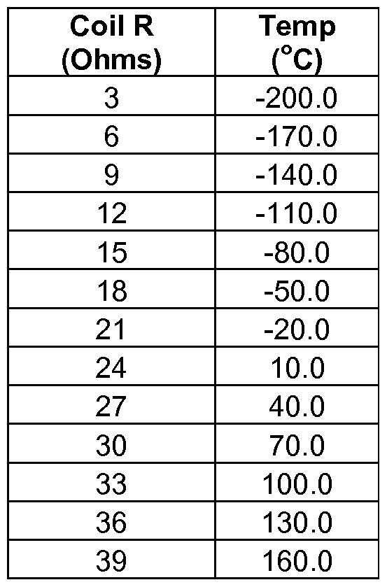
- FIG. 5 shows a correlation graph 500 that relates a coil resistance to a coil temperature. Therefore, in some embodiments, the temperature determination signal can be supplied to the sensor component and the resulting signal can comprise a resistance as determined by an ohmmeter (not shown). The ohmmeter may comprise an integral or an external component to the meter electronics 220. The correlation graph 500 may therefore provide a direct correlation between a coil resistance as determined by the ohmmeter and the coil temperature without the need to determine a V/I ratio.
- Another correlation may be in the form of a look-up table as provided in table 1 below.
- Table 1 may be generated during an initial calibration routine wherein the coil is subjected to various predetermined temperatures, using an oven, for example.
- the temperature may alternatively or additionally be confirmed with a temperature- measuring device, such as a RTD.
- Table 1 was generated using the same applied current as described above for the equation correlation. As can be appreciated, the temperature can be obtained by interpolation using the determined resistance of 30.4
- the examples above provide a correlation between resistance and temperature
- other correlations may be used.
- a similar correlation can alternatively be provided between impedance and temperature in order to take into account the inductive reactance term in equation (2).
- the value of interest is the ratio of V/I, and not necessarily only the resistance. Therefore, the look-up table or graph may comprise a correlation of V/I vs. temperature.
- this approach is used, a more accurate calibration can be obtained if the current is at the same frequency and amperage during the generation of the correlation as it is during the operation in order to account for the inductive reactance term of equation (2), which varies with the coil's inductance and frequency.
- the temperature determination signal 313 comprised an alternating current at a frequency different from the drive signal frequency 311.
- the temperature determination signal 313 can supply the sensor component with a fixed voltage instead.
- the resulting current could be measured using an ammeter rather than the voltage in order to determine the voltage-to-current ratio (V/I).
- the temperature determination signal 313 can comprise a DC signal.
- the impedance is effectively zero and does not need to be estimated or neglected.
- the meter electronics 220 can utilize the drive signal 311 to determine the temperature of the drive coil 204A using a drive signal temperature routine 317 rather than supplying a secondary signal.
- the temperature determination signal 313 can comprise the drive signal 311.
- FIG. 6 shows the drive signal temperature routine 317 according to an embodiment of the invention.
- the meter electronics 220 can be configured to perform the drive signal temperature routine 317.
- the drive signal temperature routine 317 starts in step 601 where a temperature determination signal is supplied to the drive coil 204A.
- the temperature determination signal may comprise the drive signal 311 supplied to the drive coil 204A.
- the drive signal 311 can comprise an alternating current with a known amplitude and frequency.
- the drive signal 311 used in the drive signal temperature routine 317 may comprise the same drive signal 311 used during normal operation of the vibrating meter 200.
- the drive signal 311 can be provided to vibrate the one or more conduits 203A, 203B at a resonant frequency of the process fluid filled conduit.
- step 602 the resulting voltage is determined as discussed above.
- step 603 the drive signal 311 is removed for a predetermined time.
- the drive signal 311 is dropped to zero because the drive signal 311 is supplied at a resonant frequency of the fluid filled conduits. Consequently, with the drive signal 311 supplied to the drive coil 204A, the conduits 203A, 203B are vibrating at a resonant frequency.
- the measured voltage V c is influenced by the drive signal current, the resistance across the drive coil, the inductance of the drive coil as well as back electromotive force (EMF), which is a voltage that opposes the current as provided in equation (5).
- EMF back electromotive force
- V c I(R + jlTtfL + back EMF (5)
- V c is the voltage
- R is the resistance
- j is the square route of -1 ;
- f is the drive signal frequency
- L is the drive coil inductance
- step 604 a voltage across the drive coil 204A can be determined once again.
- the voltage, V c can be determined in a similar manner as described above in step 402.
- the back EMF can be determined in step 605.
- the V/I ratio using the voltage determined in step 602 can be compensated for the back EMF to determine the coil's resistance.
- the correlation between the V/I ratio and temperature may not include the back EMF. Therefore, the back EMF can be subtracted out of the V/I ratio to obtain the correct V/I ratio to be used with the correlation.
- step 606 the resistance of the drive coil 204A is determined. More specifically, the ratio of V/I is determined. As with the previously described embodiment, while “resistance” is described, if the inductance, L of the drive coil is known, the impedance can be calculated rather than the resistance.
- step 607 the temperature of the drive coil 204A can be determined as discussed above.
- the correlation between V/I and temperature or some variance thereof was previously determined. However, it may be desirable to update or perform an initial correlation on a vibrating meter according to the correlation routine 320 described below.
- FIG. 7 shows a correlation routine 320 according to an embodiment of the invention.
- the correlation routine 330 may be performed by the meter electronics 220, for example.
- the correlation routine 330 may be performed by a user or operator.
- the correlation routine 330 may be performed by a manufacturer.
- the correlation routine 320 can be performed in order to generate a correlation between a V/I ratio and a temperature of one or more of the vibrating meter's sensor components.
- the correlation routine 320 can be performed in order to generate a correlation between a resistance of the drive coil 204A and the temperature of the drive coil 204A.
- the correlation routine 320 starts in step 701 where a test signal is supplied to the sensor component, in this case a driver coil 204A is assumed.
- the test signal may comprise an alternating current, for example.
- the test signal may comprise a fixed voltage or a direct current.
- a first resulting signal is measured.
- the resulting signal may comprise a voltage in the case where the test signal comprises an alternating current.
- the resulting signal may comprise a measured current if a fixed voltage is supplied as the test signal.
- a first V/I ratio is determined based on the test signal and the first resulting signal.
- the V/I ratio may comprise a resistance of the sensor component.
- the V/I ratio may comprise an impedance of the sensor component.
- the V/I ratio may comprise a combination of resistance and/or impedance and/or back EMF.
- a first temperature is measured.
- the temperature may be measured from a temperature-measuring device such as a RTD or a thermocouple, for example.
- the temperature-measuring device may be coupled to the sensor component or positioned proximate the sensor component.
- the correlation routine 320 may occur when a steady state has been reached such that the temperature of the temperature-measuring device comprises the temperature of the sensor component. The temperature may also be ensured by operating the calibration in an oven.
- step 705 the first V/I ratio is stored with the first measured temperature.
- step 706 the temperature is measured once again to obtain a second temperature measurement. If the second temperature is different from the first measured temperature by more than a threshold amount, the correlation routine 320 may return to step 702 where a second resulting signal is determined. If the second temperature is the same as the previously measured temperature, or within a threshold difference, the correlation routine 320 may end.
- the temperature of the system can be varied in order to obtain a plurality of correlations between the V/I ratio and temperature.
- the plurality of correlations can be stored in a variety of ways including tables, charts, graphs, equations, etc., which can be retrieved during use in order to determine the temperature of the sensor component.
- the present invention as described above provides a method and apparatus for determining a temperature of a sensor component of a vibrating meter.
- the present invention utilizes a correlation between V/I and temperature for the sensor component itself.
- the temperature of the sensor component can be determined, which may then be utilized to determine a temperature of the conduit to which the sensor component is coupled.
Landscapes
- Physics & Mathematics (AREA)
- General Physics & Mathematics (AREA)
- Engineering & Computer Science (AREA)
- Fluid Mechanics (AREA)
- Theoretical Computer Science (AREA)
- Signal Processing (AREA)
- Databases & Information Systems (AREA)
- Mathematical Physics (AREA)
- Software Systems (AREA)
- General Engineering & Computer Science (AREA)
- Data Mining & Analysis (AREA)
- Measuring Volume Flow (AREA)
- Measuring Temperature Or Quantity Of Heat (AREA)
- Measurement Of Mechanical Vibrations Or Ultrasonic Waves (AREA)
Abstract
Description

Claims
Priority Applications (14)
| Application Number | Priority Date | Filing Date | Title |
|---|---|---|---|
| RU2013109302/28A RU2545081C2 (en) | 2010-08-02 | 2010-08-02 | Method and device to detect temperature of element of vibration sensor in vibration meter |
| KR1020137005314A KR20130093108A (en) | 2010-08-02 | 2010-08-02 | Method and apparatus for determining a temperature of a vibrating sensor component of a vibrating meter |
| EP10742957.3A EP2601487B1 (en) | 2010-08-02 | 2010-08-02 | Method and apparatus for determining a temperature of a vibrating sensor component of a vibrating meter |
| CN2010800683785A CN103154678A (en) | 2010-08-02 | 2010-08-02 | Method and apparatus for determining a temperature of a vibrating sensor component of a vibrating meter |
| KR1020167013951A KR101869733B1 (en) | 2010-08-02 | 2010-08-02 | Method and apparatus for determining a temperature of a vibrating sensor component of a vibrating meter |
| JP2013523127A JP5560375B2 (en) | 2010-08-02 | 2010-08-02 | Method and apparatus for determining the temperature of a vibration sensor component of a vibration meter |
| CA2806150A CA2806150C (en) | 2010-08-02 | 2010-08-02 | Method and apparatus for determining a temperature of a vibrating sensor component of a vibrating meter |
| CN201811306532.2A CN109341798A (en) | 2010-08-02 | 2010-08-02 | For determining the method and device of the temperature of the vibrating sensor component of vibrometer |
| BR112013002138A BR112013002138B1 (en) | 2010-08-02 | 2010-08-02 | method for determining a temperature of a vibration sensor component, and, for generating a correlation between a voltage-to-current ratio and temperature of a sensor component, and meter electronics |
| US13/809,334 US9435695B2 (en) | 2010-08-02 | 2010-08-02 | Method and apparatus for determining a temperature of a vibrating sensor component of a vibrating meter |
| MX2013000647A MX2013000647A (en) | 2010-08-02 | 2010-08-02 | Method and apparatus for determining a temperature of a vibrating sensor component of a vibrating meter. |
| AU2010358559A AU2010358559B2 (en) | 2010-08-02 | 2010-08-02 | Method and apparatus for determining a temperature of a vibrating sensor component of a vibrating meter |
| PCT/US2010/044071 WO2012018323A1 (en) | 2010-08-02 | 2010-08-02 | Method and apparatus for determining a temperature of a vibrating sensor component of a vibrating meter |
| SG2013002639A SG187056A1 (en) | 2010-08-02 | 2010-08-02 | Method and apparatus for determining a temperature of a vibrating sensor component of a vibrating meter |
Applications Claiming Priority (1)
| Application Number | Priority Date | Filing Date | Title |
|---|---|---|---|
| PCT/US2010/044071 WO2012018323A1 (en) | 2010-08-02 | 2010-08-02 | Method and apparatus for determining a temperature of a vibrating sensor component of a vibrating meter |
Publications (1)
| Publication Number | Publication Date |
|---|---|
| WO2012018323A1 true WO2012018323A1 (en) | 2012-02-09 |
Family
ID=44227820
Family Applications (1)
| Application Number | Title | Priority Date | Filing Date |
|---|---|---|---|
| PCT/US2010/044071 WO2012018323A1 (en) | 2010-08-02 | 2010-08-02 | Method and apparatus for determining a temperature of a vibrating sensor component of a vibrating meter |
Country Status (12)
| Country | Link |
|---|---|
| US (1) | US9435695B2 (en) |
| EP (1) | EP2601487B1 (en) |
| JP (1) | JP5560375B2 (en) |
| KR (2) | KR101869733B1 (en) |
| CN (2) | CN103154678A (en) |
| AU (1) | AU2010358559B2 (en) |
| BR (1) | BR112013002138B1 (en) |
| CA (1) | CA2806150C (en) |
| MX (1) | MX2013000647A (en) |
| RU (1) | RU2545081C2 (en) |
| SG (1) | SG187056A1 (en) |
| WO (1) | WO2012018323A1 (en) |
Cited By (11)
| Publication number | Priority date | Publication date | Assignee | Title |
|---|---|---|---|---|
| DE102014103430A1 (en) | 2014-03-13 | 2015-09-17 | Endress + Hauser Flowtec Ag | Converter device and thus formed measuring system |
| DE102014103427A1 (en) | 2014-03-13 | 2015-09-17 | Endress + Hauser Flowtec Ag | Converter device and thus formed measuring system |
| EP3045877A1 (en) * | 2015-01-15 | 2016-07-20 | Krohne AG | Method for operating a coriolis mass flow measuring device |
| DE102016112600A1 (en) | 2016-07-08 | 2018-01-11 | Endress + Hauser Flowtec Ag | measuring system |
| DE102016112599A1 (en) | 2016-07-08 | 2018-01-11 | Endress + Hauser Flowtec Ag | measuring system |
| WO2018017080A1 (en) * | 2016-07-20 | 2018-01-25 | Micro Motion, Inc. | Method for performing temperature compensation of maximum sensor current and test tone amplitude during meter verification |
| WO2018121930A1 (en) | 2016-12-29 | 2018-07-05 | Endress+Hauser Flowtec Ag | Vibronic measuring system for measuring a mass flow rate |
| DE102017106211A1 (en) | 2016-12-29 | 2018-07-05 | Endress+Hauser Flowtec Ag | Vibronic measuring system for measuring a mass flow rate |
| WO2018121929A1 (en) | 2016-12-29 | 2018-07-05 | Endress+Hauser Flowtec Ag | Vibronic measuring system for measuring a mass flow rate |
| DE102018132672A1 (en) * | 2018-12-18 | 2020-06-18 | Endress+Hauser Flowtec Ag | Vibronic sensor with at least two temperature sensors |
| WO2022022890A1 (en) | 2020-07-29 | 2022-02-03 | Endress+Hauser Flowtec Ag | Method for ascertaining the temperature of a substance to be measured, and measuring system for this purpose |
Families Citing this family (12)
| Publication number | Priority date | Publication date | Assignee | Title |
|---|---|---|---|---|
| AU2010363965B2 (en) * | 2010-11-16 | 2014-10-23 | Micro Motion, Inc. | Multiple temperature sensor system |
| CN104011512B (en) * | 2011-10-26 | 2017-04-12 | 微动公司 | Collocated sensor for vibrating fluid meter |
| JP5974518B2 (en) * | 2012-02-06 | 2016-08-23 | 横河電機株式会社 | Coriolis mass flow meter |
| MX354264B (en) * | 2013-07-19 | 2018-02-21 | Micro Motion Inc | Auto switching referral matrices in determining process material concentration. |
| CN114112020A (en) * | 2016-02-26 | 2022-03-01 | 高准公司 | Determining vibration sensor type |
| CN109997018B (en) * | 2016-11-30 | 2021-11-30 | 高准公司 | Temperature compensation of test tones used in meter verification |
| KR102012841B1 (en) | 2017-08-11 | 2019-08-21 | 양희준 | Preflex girder and manufacturing method thereof |
| KR101897660B1 (en) | 2017-11-01 | 2018-09-12 | 김민중 | Prestressed steel girder and manufacturing method thereof |
| DE102018102379B4 (en) * | 2018-02-02 | 2023-02-02 | Endress + Hauser Flowtec Ag | Coriolis measuring sensor of a Coriolis measuring device with a temperature measuring device integrated in the vibration exciter or vibration sensor and such a Coriolis measuring device |
| NL2023792B1 (en) * | 2019-08-16 | 2021-03-24 | Illumina Inc | Method for measuring thermal resistance at interface between consumable and thermocycler |
| DE102019134600A1 (en) * | 2019-12-16 | 2021-06-17 | Endress + Hauser Flowtec Ag | Sensor and Coriolis measuring device |
| US11300435B2 (en) * | 2020-04-10 | 2022-04-12 | Malema Engineering Corporation | Coriolis mass flow sensors having different resonant frequencies |
Citations (9)
| Publication number | Priority date | Publication date | Assignee | Title |
|---|---|---|---|---|
| US4109524A (en) | 1975-06-30 | 1978-08-29 | S & F Associates | Method and apparatus for mass flow rate measurement |
| USRE31450E (en) | 1977-07-25 | 1983-11-29 | Micro Motion, Inc. | Method and structure for flow measurement |
| US4491025A (en) | 1982-11-03 | 1985-01-01 | Micro Motion, Inc. | Parallel path Coriolis mass flow rate meter |
| US6230104B1 (en) | 1997-09-30 | 2001-05-08 | Micro Motion, Inc. | Combined pickoff and oscillatory driver for use in coriolis flowmeters and method of operating the same |
| US20030235233A1 (en) * | 2002-06-24 | 2003-12-25 | Nohken Inc. | Temperature measuring method, object detecting method and object detecting device with vibrating-type level sensor |
| US20050125167A1 (en) * | 2003-10-31 | 2005-06-09 | Abb Patent Gmbh | Device and method for operating a Coriolis mass flowmeter |
| US20060179895A1 (en) * | 2005-02-14 | 2006-08-17 | Emerson Electric Co. | Device and method for sensing temperature of a rotating electromagnetic machine |
| US7287438B2 (en) | 2003-04-17 | 2007-10-30 | Micro Motion, Inc. | Method and apparatus for force balancing of a Coriolis flow meter |
| US7628083B2 (en) | 2004-04-16 | 2009-12-08 | Micro Motion, Inc. | Method and apparatus for force balancing |
Family Cites Families (21)
| Publication number | Priority date | Publication date | Assignee | Title |
|---|---|---|---|---|
| AU580623B2 (en) * | 1984-07-11 | 1989-01-19 | Exac Corporation | Coriolis mass flow rate meter |
| JPH04340424A (en) * | 1991-05-17 | 1992-11-26 | Yamatake Honeywell Co Ltd | Electromagnetic flowmeter |
| JP3175887B2 (en) * | 1992-10-27 | 2001-06-11 | 株式会社半導体エネルギー研究所 | measuring device |
| JP4004148B2 (en) | 1998-04-06 | 2007-11-07 | 株式会社ノーケン | Vibration type level detector |
| US5987998A (en) * | 1998-08-26 | 1999-11-23 | Micro Motion, Inc. | High temperature drive system for a coriolis mass flowmeter |
| JP3753057B2 (en) * | 2001-12-04 | 2006-03-08 | 株式会社日立製作所 | Gas flow measuring device |
| DE102004019189B3 (en) * | 2004-04-16 | 2005-08-18 | Krohne Ag | Magnetic-inductive throughflow measurement method involves selecting second temperature measurement point so second temperature depends on medium's temperature or/and ambient temperature differently than first temperature |
| US7694584B2 (en) * | 2004-06-14 | 2010-04-13 | Micro Motion, Inc. | Coriolis flow meter and method for determining a signal difference in cabling and first and second pickoff sensors |
| CN1285889C (en) * | 2004-09-01 | 2006-11-22 | 西安东风机电有限公司 | Double C-type tube coriodis mass flow meter |
| US7000465B1 (en) * | 2004-09-17 | 2006-02-21 | Mks Instruments, Inc. | Attitude error self-correction for thermal sensors of mass flow meters and controllers |
| RU2344376C1 (en) | 2004-09-17 | 2009-01-20 | Эмерсон Электрик Ко. | Method and device for compensating coriolis flow meter |
| KR101250854B1 (en) | 2004-09-17 | 2013-04-04 | 에머슨 일렉트릭 컴파니 | Compensation method and apparatus for a coriolis flow meter |
| CN100595539C (en) * | 2005-08-01 | 2010-03-24 | 李韫言 | Thermal sensor using micro machining heat separation structure and preparation thereof |
| EP1989517B1 (en) * | 2006-02-13 | 2015-09-02 | Invensys Systems, Inc. | Compensating for frequency change in flowmeters |
| JP4913548B2 (en) * | 2006-10-31 | 2012-04-11 | 株式会社山武 | Capacity type electromagnetic flow meter |
| US7550979B2 (en) | 2007-05-29 | 2009-06-23 | Georg Fischer Signet Llc | System and method for measuring conductivity of fluid |
| DK2168024T3 (en) * | 2007-06-28 | 2013-04-08 | Micro Motion Inc | Instrument power regulator and method of adaptively providing an output voltage and an output current which together maintain a substantially constant electrical output power |
| JP4598100B2 (en) * | 2008-04-17 | 2010-12-15 | 三菱電機株式会社 | Transmission control device |
| JP4469008B1 (en) * | 2008-11-18 | 2010-05-26 | 株式会社オーバル | Coriolis flow meter |
| DE102009030903B4 (en) * | 2009-06-26 | 2013-06-27 | Krohne Ag | Method for operating a mass flowmeter and mass flowmeter |
| AU2010363965B2 (en) | 2010-11-16 | 2014-10-23 | Micro Motion, Inc. | Multiple temperature sensor system |
-
2010
- 2010-08-02 WO PCT/US2010/044071 patent/WO2012018323A1/en active Application Filing
- 2010-08-02 KR KR1020167013951A patent/KR101869733B1/en active IP Right Grant
- 2010-08-02 CN CN2010800683785A patent/CN103154678A/en active Pending
- 2010-08-02 BR BR112013002138A patent/BR112013002138B1/en active IP Right Grant
- 2010-08-02 KR KR1020137005314A patent/KR20130093108A/en not_active Application Discontinuation
- 2010-08-02 AU AU2010358559A patent/AU2010358559B2/en active Active
- 2010-08-02 US US13/809,334 patent/US9435695B2/en active Active
- 2010-08-02 RU RU2013109302/28A patent/RU2545081C2/en active
- 2010-08-02 EP EP10742957.3A patent/EP2601487B1/en active Active
- 2010-08-02 SG SG2013002639A patent/SG187056A1/en unknown
- 2010-08-02 CN CN201811306532.2A patent/CN109341798A/en active Pending
- 2010-08-02 MX MX2013000647A patent/MX2013000647A/en active IP Right Grant
- 2010-08-02 JP JP2013523127A patent/JP5560375B2/en active Active
- 2010-08-02 CA CA2806150A patent/CA2806150C/en active Active
Patent Citations (10)
| Publication number | Priority date | Publication date | Assignee | Title |
|---|---|---|---|---|
| US4109524A (en) | 1975-06-30 | 1978-08-29 | S & F Associates | Method and apparatus for mass flow rate measurement |
| USRE31450E (en) | 1977-07-25 | 1983-11-29 | Micro Motion, Inc. | Method and structure for flow measurement |
| US4491025A (en) | 1982-11-03 | 1985-01-01 | Micro Motion, Inc. | Parallel path Coriolis mass flow rate meter |
| US4491025B1 (en) | 1982-11-03 | 1988-01-05 | ||
| US6230104B1 (en) | 1997-09-30 | 2001-05-08 | Micro Motion, Inc. | Combined pickoff and oscillatory driver for use in coriolis flowmeters and method of operating the same |
| US20030235233A1 (en) * | 2002-06-24 | 2003-12-25 | Nohken Inc. | Temperature measuring method, object detecting method and object detecting device with vibrating-type level sensor |
| US7287438B2 (en) | 2003-04-17 | 2007-10-30 | Micro Motion, Inc. | Method and apparatus for force balancing of a Coriolis flow meter |
| US20050125167A1 (en) * | 2003-10-31 | 2005-06-09 | Abb Patent Gmbh | Device and method for operating a Coriolis mass flowmeter |
| US7628083B2 (en) | 2004-04-16 | 2009-12-08 | Micro Motion, Inc. | Method and apparatus for force balancing |
| US20060179895A1 (en) * | 2005-02-14 | 2006-08-17 | Emerson Electric Co. | Device and method for sensing temperature of a rotating electromagnetic machine |
Cited By (16)
| Publication number | Priority date | Publication date | Assignee | Title |
|---|---|---|---|---|
| DE102014103430A1 (en) | 2014-03-13 | 2015-09-17 | Endress + Hauser Flowtec Ag | Converter device and thus formed measuring system |
| DE102014103427A1 (en) | 2014-03-13 | 2015-09-17 | Endress + Hauser Flowtec Ag | Converter device and thus formed measuring system |
| EP3045877A1 (en) * | 2015-01-15 | 2016-07-20 | Krohne AG | Method for operating a coriolis mass flow measuring device |
| CN105806432A (en) * | 2015-01-15 | 2016-07-27 | 克洛纳有限公司 | Method for operating a coriolis mass flow measuring device |
| DE102016112600A1 (en) | 2016-07-08 | 2018-01-11 | Endress + Hauser Flowtec Ag | measuring system |
| DE102016112599A1 (en) | 2016-07-08 | 2018-01-11 | Endress + Hauser Flowtec Ag | measuring system |
| WO2018007176A1 (en) | 2016-07-08 | 2018-01-11 | Endress+Hauser Flowtec Ag | Vibration-type fluid flow-rate measuring system having temperature compensation |
| WO2018007185A1 (en) | 2016-07-08 | 2018-01-11 | Endress+Hauser Flowtec Ag | Measuring system |
| WO2018017080A1 (en) * | 2016-07-20 | 2018-01-25 | Micro Motion, Inc. | Method for performing temperature compensation of maximum sensor current and test tone amplitude during meter verification |
| WO2018121930A1 (en) | 2016-12-29 | 2018-07-05 | Endress+Hauser Flowtec Ag | Vibronic measuring system for measuring a mass flow rate |
| DE102017106211A1 (en) | 2016-12-29 | 2018-07-05 | Endress+Hauser Flowtec Ag | Vibronic measuring system for measuring a mass flow rate |
| DE102017106209A1 (en) | 2016-12-29 | 2018-07-05 | Endress+Hauser Flowtec Ag | Vibronic measuring system for measuring a mass flow rate |
| WO2018121929A1 (en) | 2016-12-29 | 2018-07-05 | Endress+Hauser Flowtec Ag | Vibronic measuring system for measuring a mass flow rate |
| DE102018132672A1 (en) * | 2018-12-18 | 2020-06-18 | Endress+Hauser Flowtec Ag | Vibronic sensor with at least two temperature sensors |
| WO2022022890A1 (en) | 2020-07-29 | 2022-02-03 | Endress+Hauser Flowtec Ag | Method for ascertaining the temperature of a substance to be measured, and measuring system for this purpose |
| DE102020120054A1 (en) | 2020-07-29 | 2022-02-03 | Endress + Hauser Flowtec Ag | Method for determining a fluid temperature and measuring system for it |
Also Published As
| Publication number | Publication date |
|---|---|
| KR20130093108A (en) | 2013-08-21 |
| SG187056A1 (en) | 2013-02-28 |
| AU2010358559A1 (en) | 2013-01-31 |
| EP2601487A1 (en) | 2013-06-12 |
| AU2010358559B2 (en) | 2013-11-07 |
| CN109341798A (en) | 2019-02-15 |
| KR101869733B1 (en) | 2018-06-21 |
| BR112013002138B1 (en) | 2019-12-10 |
| BR112013002138A2 (en) | 2016-05-24 |
| CN103154678A (en) | 2013-06-12 |
| RU2545081C2 (en) | 2015-03-27 |
| CA2806150A1 (en) | 2012-02-09 |
| JP5560375B2 (en) | 2014-07-23 |
| US9435695B2 (en) | 2016-09-06 |
| EP2601487B1 (en) | 2021-11-03 |
| KR20160063427A (en) | 2016-06-03 |
| RU2013109302A (en) | 2014-09-20 |
| CA2806150C (en) | 2016-12-06 |
| JP2013532840A (en) | 2013-08-19 |
| MX2013000647A (en) | 2013-04-03 |
| US20130121376A1 (en) | 2013-05-16 |
Similar Documents
| Publication | Publication Date | Title |
|---|---|---|
| CA2806150C (en) | Method and apparatus for determining a temperature of a vibrating sensor component of a vibrating meter | |
| JP4588293B2 (en) | Apparatus and method for compensating mass flow rate of a material when an unacceptable error in flow rate occurs due to the density of the material | |
| EP2729771B1 (en) | Method and apparatus for determining differential flow characteristics of a multiple meter fluid flow system | |
| EP2435801B1 (en) | Method and apparatus for determining a flow rate error in a vibrating flow meter | |
| EP1421346B1 (en) | A majority component proportion determination of a fluid using a coriolis flowmeter | |
| EP3209977B1 (en) | Apparatus for applying a variable zero algorithm in a vibrating flowmeter and related method | |
| JP2004521319A5 (en) | ||
| EP3411672B1 (en) | Pressure compensation for a vibrating flowmeter and related method |
Legal Events
| Date | Code | Title | Description |
|---|---|---|---|
| WWE | Wipo information: entry into national phase |
Ref document number: 201080068378.5 Country of ref document: CN |
|
| 121 | Ep: the epo has been informed by wipo that ep was designated in this application |
Ref document number: 10742957 Country of ref document: EP Kind code of ref document: A1 |
|
| WWE | Wipo information: entry into national phase |
Ref document number: 13809334 Country of ref document: US |
|
| WWE | Wipo information: entry into national phase |
Ref document number: MX/A/2013/000647 Country of ref document: MX |
|
| ENP | Entry into the national phase |
Ref document number: 2806150 Country of ref document: CA |
|
| ENP | Entry into the national phase |
Ref document number: 2010358559 Country of ref document: AU Date of ref document: 20100802 Kind code of ref document: A |
|
| ENP | Entry into the national phase |
Ref document number: 2013523127 Country of ref document: JP Kind code of ref document: A |
|
| NENP | Non-entry into the national phase |
Ref country code: DE |
|
| ENP | Entry into the national phase |
Ref document number: 20137005314 Country of ref document: KR Kind code of ref document: A |
|
| WWE | Wipo information: entry into national phase |
Ref document number: 2010742957 Country of ref document: EP |
|
| ENP | Entry into the national phase |
Ref document number: 2013109302 Country of ref document: RU Kind code of ref document: A |
|
| REG | Reference to national code |
Ref country code: BR Ref legal event code: B01A Ref document number: 112013002138 Country of ref document: BR |
|
| ENP | Entry into the national phase |
Ref document number: 112013002138 Country of ref document: BR Kind code of ref document: A2 Effective date: 20130129 |