WO2011129336A1 - Connector - Google Patents
Connector Download PDFInfo
- Publication number
- WO2011129336A1 WO2011129336A1 PCT/JP2011/059097 JP2011059097W WO2011129336A1 WO 2011129336 A1 WO2011129336 A1 WO 2011129336A1 JP 2011059097 W JP2011059097 W JP 2011059097W WO 2011129336 A1 WO2011129336 A1 WO 2011129336A1
- Authority
- WO
- WIPO (PCT)
- Prior art keywords
- connector
- housing
- bus bar
- fuse
- opening
- Prior art date
Links
Images


Classifications
-
- H—ELECTRICITY
- H01—ELECTRIC ELEMENTS
- H01R—ELECTRICALLY-CONDUCTIVE CONNECTIONS; STRUCTURAL ASSOCIATIONS OF A PLURALITY OF MUTUALLY-INSULATED ELECTRICAL CONNECTING ELEMENTS; COUPLING DEVICES; CURRENT COLLECTORS
- H01R13/00—Details of coupling devices of the kinds covered by groups H01R12/70 or H01R24/00 - H01R33/00
- H01R13/66—Structural association with built-in electrical component
- H01R13/68—Structural association with built-in electrical component with built-in fuse
- H01R13/684—Structural association with built-in electrical component with built-in fuse the fuse being removable
- H01R13/688—Structural association with built-in electrical component with built-in fuse the fuse being removable with housing part adapted for accessing the fuse
-
- H—ELECTRICITY
- H01—ELECTRIC ELEMENTS
- H01R—ELECTRICALLY-CONDUCTIVE CONNECTIONS; STRUCTURAL ASSOCIATIONS OF A PLURALITY OF MUTUALLY-INSULATED ELECTRICAL CONNECTING ELEMENTS; COUPLING DEVICES; CURRENT COLLECTORS
- H01R13/00—Details of coupling devices of the kinds covered by groups H01R12/70 or H01R24/00 - H01R33/00
- H01R13/46—Bases; Cases
- H01R13/52—Dustproof, splashproof, drip-proof, waterproof, or flameproof cases
- H01R13/5219—Sealing means between coupling parts, e.g. interfacial seal
-
- H—ELECTRICITY
- H01—ELECTRIC ELEMENTS
- H01R—ELECTRICALLY-CONDUCTIVE CONNECTIONS; STRUCTURAL ASSOCIATIONS OF A PLURALITY OF MUTUALLY-INSULATED ELECTRICAL CONNECTING ELEMENTS; COUPLING DEVICES; CURRENT COLLECTORS
- H01R13/00—Details of coupling devices of the kinds covered by groups H01R12/70 or H01R24/00 - H01R33/00
- H01R13/73—Means for mounting coupling parts to apparatus or structures, e.g. to a wall
- H01R13/74—Means for mounting coupling parts in openings of a panel
Definitions
- the present invention relates to a connector for connecting an electric wire to, for example, a device mounted on a vehicle.
- FIG. 9 shows a conventional example of a connector for connecting a shielded wire to a device mounted on a vehicle.
- the connector 101 shown here is a connector that connects a shielded wire to a terminal (not shown) in the in-vehicle device 110, and is disclosed in Patent Document 1 below.
- the connector 101 accommodates two bus bars 103 arranged in a direction orthogonal to the paper surface in the drawing, a fuse 105 that connects the two bus bars 103 so as to be blown, and the bus bar 103 and the fuse 105. And a resin housing 107.
- the bus bar 103 is a press-formed product of a metal plate, and is a device tab 103a inserted into the device 110 and connected to a circuit in the device 110, and an external wire tab connected to a shielded wire (not shown) from the outside. 103b.
- the fuse 105 has one end screwed to one bus bar 103 and the other end screwed to the other bus bar 103 so that the two bus bars 103 are electrically connected so as to be fused.
- the bus bar 103 to be accommodated is fixed by a resin mold.
- the housing 107 can be opened / closed by an opening / closing cover 108 at an upper portion located outside the device 110.
- FIG. 9 shows a state in which the opening / closing cover 108 is opened.
- the open / close cover 108 is opened, the upper side of the fuse accommodating portion 107a in the housing 107 is opened to the outside, and the fuse 105 can be attached and detached from the opened portion.
- a shield cover 109 that covers the outer periphery of the housing 107 and electromagnetically shields the inside and outside of the housing 107 is attached to the housing 107.
- FIGS. 10 to 12 show other conventional examples of connectors for connecting shielded wires to equipment mounted on a vehicle.
- FIG. 10 is a perspective view of an assembled state of a connector as another conventional example
- FIG. 11 is a perspective view of a state in which the open / close cover of the connector as another conventional example is opened and a fuse in the housing is removable
- FIG. It is a perspective view of the state which removed the fuse from the inside of a housing.
- the connector 121 as another conventional example also connects a shielded wire to a terminal in an in-vehicle device. Like the connector 101 shown in FIG. 9, two bus bars 123 and a space between these two bus bars 123 are also used. And a fuse housing 125 that houses the bus bar 123 and the fuse 125.
- the bus bar 123 is a press-formed product of a metal plate, and is inserted into an in-vehicle device (not shown) and connected to a circuit in the device, and a shielded electric wire 141 from the outside. And an unillustrated tab for external electric wires connected to the.
- the fuse 125 has one end screwed to one bus bar 123 and the other end screwed to the other bus bar 123 so that the two bus bars 123 are electrically connected so as to be blown.
- a reference numeral 133 in FIG. 12 is a nut used for screwing the fuse 125.
- the housing 127 has a device mounting portion 131 for mounting on a device (not shown) extending on one side of the upper portion.
- a device not shown
- the upper portion located outside the device can be opened and closed by the opening / closing cover 128.
- FIG. 11 shows a state in which the opening / closing cover 128 is opened.
- the open / close cover 128 is opened, the upper side of the fuse accommodating portion 127a in the housing 127 is opened to the outside, and the fuse 125 can be attached and detached from the opened portion as shown in FIG.
- the connector 121 shown in FIGS. 10 to 12 also opens the fuse housing portion when the opening / closing cover 128 covering the top of the housing 127 located outside the device is opened, as in the case of the connector 101 of Patent Document 1.
- 127a is opened to the outside, so that the fuse 125 can be attached and detached.
- the connectors 101 and 121 shown in Patent Document 1 and FIGS. 10 to 12 open the opening and closing covers 108 and 128 above the housings 107 and 127 located outside the device, respectively.
- the fuses 105 and 125 are attached and detached.
- the fixing means such as screws for fastening the opening and closing covers 108 and 128 to the housing, and the opening and closing parts by the opening and closing covers 108 and 128 are made waterproof. Packing and the like for securing it are also necessary, and there is a problem that the number of parts constituting the connector increases.
- an object of the present invention is to solve the above-described problems, and in a connector in which a fuse can be attached and detached, it is possible to reduce the number of components and improve reliability, and to improve shielding performance. To provide a connector.
- the first bus bar and the second bus bar include a device tab inserted into a device and connected to a circuit in the device, and an external wire tab connected to an electric wire from the outside,
- the housing includes a hood portion that covers the periphery of the device tab and fits into a connector mounting hole of the device, and the connector in which the fuse is mounted in an accommodation space in the hood portion that is opened in the device. .
- the housing space in the connector that houses the fuse is in the hood portion of the housing that fits into the connector mounting hole of the device. Therefore, when the housing is removed from the device, the hood portion is exposed and the fuse can be attached and detached.
- the housing space which is the fuse mounting area, is not covered with an open / close cover, so the open / close cover, packing, and open / close cover are fixed to the housing compared to conventional connectors that allow the fuse mounting section to be opened and closed. All the fastening means and the like to be performed can be omitted, and the number of components in the connector can be greatly reduced.
- the opening / closing cover is not provided, there is no risk of damaging the reliability with respect to waterproofing or the like by forgetting to tighten the opening / closing cover, and the reliability of the connector can be improved.
- the gap between the hood portion of the housing and the connector mounting hole of the device is waterproofed by the packing, so that water drops enter the device from between the hood portion and the connector mounting hole. This can be prevented, and the waterproofness of the fuse accommodated in the hood portion located in the device can be improved.
- the housing has a simple structure that does not have an opening / closing cover that opens and closes the fuse mounting portion. Therefore, compared to a conventional connector having an opening / closing cover, the inside and outside of the housing are electromagnetically shielded.
- the shield cover to be covered also easily covers the outer periphery of the housing, and the shield performance can be improved.
- FIG. 2 is a perspective view of the single connector shown in FIG. 1.
- FIG. 3 is an exploded perspective view of the connector shown in FIG. 2.
- FIG. 3 is a perspective view of a first bus bar and a second bus bar housed in the connector shown in FIG. 2.
- FIG. 3 is a front view of the connector shown in FIG. 2.
- FIG. 6 is a cross-sectional view taken along line AA in FIG. 5.
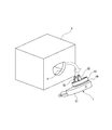
- FIG. 2 is a perspective view of a state where the connector shown in FIG. 1 is attached to a device. It is a perspective view in the state where a connector was removed from a device.
- FIG. 1 to 6 show an embodiment of a connector according to the present invention.
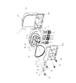
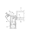
- FIG. 1 is a longitudinal sectional view of the connector of the embodiment attached to a device
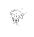
- FIG. 2 is a view of the connector shown in FIG.
- FIG. 3 is an exploded perspective view of the connector shown in FIG. 2
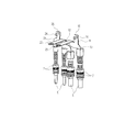
- FIG. 4 is a perspective view of the first bus bar and the second bus bar accommodated in the connector shown in FIG. 2
- FIG. FIG. 6 is a cross-sectional view taken along the line AA in FIG. 5.
- the connector 1 is a so-called shield connector for connecting a shielded wire 5 to a device 3 mounted on a vehicle, and includes a first bus bar 11, a second bus bar 21 separate from the first bus bar 11, and one end. Are screwed to the first bus bar 11 and the other end is screwed to the second bus bar 21 to connect the first bus bar 11 and the second bus bar 21 in a fusible manner, and the first bus bar 11 A housing 41 that houses the second bus bar 21 and the fuse 31, and a shield cover 51 that covers the outer periphery of the housing 41.
- the first bus bar 11 and the second bus bar 21 are made of sheet metal, and as shown in FIGS. 1 and 4, device tabs 12 and 22 that are inserted into the device 3 and connected to circuits in the device 3, and external The external electric wire tabs 13 and 23 connected to the shielded electric wire 5 which is an electric wire from the outside and the stud bolts 14 and 24 for screwing the fuse 31 are provided.
- the shield terminal 7 is fitted and attached to the shield layer (braided wire) of the shielded wire 5 connected to the external wire tabs 13 and 23.
- the stud bolts 14 and 24 are implanted in the ear portions 15 and 25 for fuse connection formed integrally with the bus bars 11 and 21.
- the fuse 31 has bolt insertion holes 33 through which the stud bolts 14 and 24 are inserted in the connection terminal portions 32 at both ends.
- the connection terminal portions 32 at both ends of the fuse 31 are screwed to the ear portions 15 and 25 of the bus bars 11 and 21 by tightening the nuts 35 screwed into the stud bolts 14 and 24. Since the connection terminal portions 32 at both ends are screwed to the bus bars 11 and 21, the fuse 31 electrically connects the first bus bar 11 and the second bus bar 21 so as to be blown.
- the housing 41 is made of resin.
- the first bus bar 11 and the second bus bar 21 housed in the housing 41 are fixed in the housing 41 by insert molding when molding the housing 41 or resin molding.
- the housing 41 of this embodiment includes a cylindrical hood portion 43 that covers the periphery of the device tabs 12 and 22 and fits into the connector mounting hole 6 of the device 3. .
- the housing 41 in the present embodiment has a fuse 31 attached to a housing space 45 in a hood portion 43 that opens into the device 3.
- the shape and dimensions of the bus bars 11 and 21 are set so that the fuse 31 is screwed to the bus bars 11 and 21 in the accommodation space 45.
- a seal groove 49 for mounting the ring-shaped packing 48 is formed on the outer periphery of the hood portion 43.
- the packing 48 attached to the hood portion 43 is closely fitted to the connector mounting hole 6 when the hood portion 43 is fitted to the connector mounting hole 6. Seal the space liquid tightly.
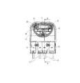
- the shield cover 51 includes a first shield shell 53 that covers the housing 41 from the side opposite to the device 3, and a second shield shell 54 that covers the housing 41 from the device 3 side.
- the first shield shell 53 and the second shield shell 54 are attached to the housing 41 so as to sandwich the housing 41, cover most of the outer periphery of the housing 41 other than the hood portion 43, and electromagnetically shield the inside and outside of the housing 41.
- the first shield shell 53 and the second shield shell 54 are coupled to each other by fastening with bolts 61 with the housing 41 sandwiched therebetween.
- the first shield shell 53 and the second shield shell 54 have terminal contact portions 53 a and 54 a that are in close contact with the outer periphery of the shield terminal 7. It is in a state of being conductively connected to the shield layer.
- the connector 1 described above is attached to the device 3 by fitting the hood portion 43 into the connector mounting hole 6 of the device 3 as shown in FIGS. 1 and 7. Further, when the connector 1 is detached from the device 3 as shown in FIG. 8, the fuse 31 in the hood portion 43 can be attached and detached.
- the accommodating space 45 in the connector 1 that accommodates the fuse 31 is in the hood portion 43 of the housing 41 that fits into the connector mounting hole 6 of the device 3. Therefore, as shown in FIG. 8, when the housing 41 is removed from the device 3, the hood portion 43 is exposed and the fuse 31 can be attached and detached.
- the housing space 45 that is the attachment portion of the fuse 31 is not structured to be covered with an opening / closing cover, the opening / closing cover, packing, and opening / closing cover are housed in a housing as compared with a conventional connector in which the attachment portion of the fuse can be opened and closed by the opening / closing cover. All the fastening means for fixing to the connector 1 can be omitted, and the number of components in the connector 1 can be greatly reduced.
- the reliability of the connector 1 can be improved without fear of impairing the reliability of the waterproofing due to forgetting to tighten the opening / closing cover.
- the space between the hood portion 43 of the housing 41 and the connector attachment hole 6 of the device 3 is waterproofed by the packing 48, so that the hood portion 43 and the connector attachment hole 6 are protected. It is possible to prevent water droplets from entering the device 3 from between the two, and it is possible to improve the waterproofness with respect to the fuse 31 accommodated in the hood portion 43 located in the device 3.
- the housing 41 has a simple structure that does not have an opening / closing cover for opening / closing the accommodation space 45 that is the attachment portion of the fuse 31, and thus a conventional connector having an opening / closing cover.
- the shield cover 51 that electromagnetically shields the inside and outside of the housing 41 can easily cover the outer periphery of the housing 41, and the shielding performance can be improved.
- the connector of the present invention is not limited to the above-described embodiments, and appropriate modifications and improvements can be made. Further, the shape, dimensions, form, quantity, placement location, etc. of the hood part and each bus bar exemplified in the above-described embodiment are arbitrary as long as the object of the present invention can be achieved, and each of the above-described embodiments. It is not limited.
- the housing space in the connector for housing the fuse is in the hood portion of the housing that fits into the connector mounting hole of the device. Therefore, when the housing is removed from the device, the hood portion is exposed and the fuse can be attached and detached.
- the fuse mounting part is not covered with an opening / closing cover, compared to a conventional connector in which the fuse mounting part can be opened / closed by the opening / closing cover, the opening / closing cover, packing, fastening means for fixing the opening / closing cover to the housing, etc. Can be omitted, and the number of components in the connector can be greatly reduced.
- the opening / closing cover is not provided, there is no risk of damaging the reliability with respect to waterproofing or the like by forgetting to tighten the opening / closing cover, and the reliability of the connector can be improved.
Landscapes
- Details Of Connecting Devices For Male And Female Coupling (AREA)
- Connector Housings Or Holding Contact Members (AREA)
Abstract
Description
(1)第1バスバーと、前記第1バスバーとは別体の第2バスバーと、一端が前記第1バスバーにねじ止めされると共に他端が前記第2バスバーにねじ止めされて前記第1バスバーと前記第2バスバーとの間を溶断可能に導通接続するヒューズと、前記第1バスバーと前記第2バスバーと前記ヒューズとを収容するハウジングと、を備え、
前記第1バスバー及び前記第2バスバーは、機器内に挿入されて前記機器内の回路に接続される機器用タブと、外部からの電線に接続される外部電線用タブと、を備え、
前記ハウジングは、前記機器用タブの周囲を覆って前記機器のコネクタ取付け孔に嵌合するフード部を備え、前記機器内に開放する前記フード部内の収容空間に、前記ヒューズが取り付けられているコネクタ。 The above-described object of the present invention is achieved by the following configuration.
(1) A first bus bar, a second bus bar separate from the first bus bar, and one end screwed to the first bus bar and the other end screwed to the second bus bar. A fuse that is conductively connected between the second bus bar and the second bus bar, and a housing that houses the first bus bar, the second bus bar, and the fuse,
The first bus bar and the second bus bar include a device tab inserted into a device and connected to a circuit in the device, and an external wire tab connected to an electric wire from the outside,
The housing includes a hood portion that covers the periphery of the device tab and fits into a connector mounting hole of the device, and the connector in which the fuse is mounted in an accommodation space in the hood portion that is opened in the device. .
3 機器
6 コネクタ取付け孔
11 第1バスバー
12 機器用タブ
21 第2バスバー
22 機器用タブ
31 ヒューズ
41 ハウジング
43 フード部
45 収容空間
48 パッキン
51 シールドカバー
53 第1シールドシェル
54 第2シールドシェル 1 Connector (Shield connector)
3
Claims (3)
- 第1バスバーと、前記第1バスバーとは別体の第2バスバーと、一端が前記第1バスバーにねじ止めされると共に他端が前記第2バスバーにねじ止めされて前記第1バスバーと前記第2バスバーとの間を溶断可能に導通接続するヒューズと、前記第1バスバーと前記第2バスバーと前記ヒューズとを収容するハウジングと、を備え、
前記第1バスバー及び前記第2バスバーは、機器内に挿入されて前記機器内の回路に接続される機器用タブと、外部からの電線に接続される外部電線用タブと、を備え、
前記ハウジングは、前記機器用タブの周囲を覆って前記機器のコネクタ取付け孔に嵌合するフード部を備え、前記機器内に開放する前記フード部内の収容空間に、前記ヒューズが取り付けられているコネクタ。 A first bus bar, a second bus bar separate from the first bus bar, one end screwed to the first bus bar and the other end screwed to the second bus bar, the first bus bar and the first bus bar A fuse that is conductively connected between two bus bars so as to be blown, and a housing that houses the first bus bar, the second bus bar, and the fuse,
The first bus bar and the second bus bar include a device tab inserted into a device and connected to a circuit in the device, and an external wire tab connected to an electric wire from the outside,
The housing includes a hood portion that covers the periphery of the device tab and fits into a connector mounting hole of the device, and the connector in which the fuse is mounted in an accommodation space in the hood portion that is opened in the device. . - 前記フード部の外周に、前記コネクタ取付け孔との間を液密に封止するパッキンが設けられた請求項1に記載のコネクタ。 The connector according to claim 1, wherein a packing is provided on the outer periphery of the hood portion so as to liquid-tightly seal the connector mounting hole.
- 前記外部電線用タブに接続される前記電線がシールド電線であり、前記ハウジングには、前記ハウジングの外周を覆って前記ハウジング内外を電磁遮蔽するシールドカバーが装着される請求項1又は2に記載のコネクタ。 The said electric wire connected to the said external electric wire tab is a shield electric wire, The shield cover which covers the outer periphery of the said housing and electromagnetically shields the inside and outside of the said housing is mounted | worn with the said housing. connector.
Priority Applications (3)
| Application Number | Priority Date | Filing Date | Title |
|---|---|---|---|
| CN2011800020669A CN102422493A (en) | 2010-04-13 | 2011-04-12 | Connector |
| US13/379,718 US8425256B2 (en) | 2010-04-13 | 2011-04-12 | Connector |
| EP11768857.2A EP2560247B1 (en) | 2010-04-13 | 2011-04-12 | Connector |
Applications Claiming Priority (2)
| Application Number | Priority Date | Filing Date | Title |
|---|---|---|---|
| JP2010092171A JP5524687B2 (en) | 2010-04-13 | 2010-04-13 | connector |
| JP2010-092171 | 2010-04-13 |
Publications (1)
| Publication Number | Publication Date |
|---|---|
| WO2011129336A1 true WO2011129336A1 (en) | 2011-10-20 |
Family
ID=44798707
Family Applications (1)
| Application Number | Title | Priority Date | Filing Date |
|---|---|---|---|
| PCT/JP2011/059097 WO2011129336A1 (en) | 2010-04-13 | 2011-04-12 | Connector |
Country Status (5)
| Country | Link |
|---|---|
| US (1) | US8425256B2 (en) |
| EP (1) | EP2560247B1 (en) |
| JP (1) | JP5524687B2 (en) |
| CN (1) | CN102422493A (en) |
| WO (1) | WO2011129336A1 (en) |
Cited By (4)
| Publication number | Priority date | Publication date | Assignee | Title |
|---|---|---|---|---|
| WO2014136655A1 (en) * | 2013-03-04 | 2014-09-12 | 矢崎総業株式会社 | Waterproof structure for connector |
| WO2015063918A1 (en) * | 2013-10-31 | 2015-05-07 | 矢崎総業株式会社 | Connector with fuse |
| EP2725661B1 (en) * | 2011-06-23 | 2018-08-08 | Yazaki Corporation | Connector |
| WO2022118651A1 (en) * | 2020-12-04 | 2022-06-09 | 住友電装株式会社 | Connector and device unit |
Families Citing this family (39)
| Publication number | Priority date | Publication date | Assignee | Title |
|---|---|---|---|---|
| JP5565946B2 (en) * | 2010-06-15 | 2014-08-06 | 矢崎総業株式会社 | connector |
| US8734186B2 (en) * | 2010-08-18 | 2014-05-27 | Snap-On Incorporated | Cable assembly with circuit-interrupter-lead receptacles |
| JP5751194B2 (en) * | 2011-09-08 | 2015-07-22 | 日立金属株式会社 | Connector and wire harness |
| RU2510108C1 (en) * | 2012-08-21 | 2014-03-20 | Российская Федерация, от имени которой выступает Государственная корпорация по атомной энергии "Росатом" - Госкорпорация "Росатом" | Electric connector socket |
| US20140065880A1 (en) * | 2012-09-04 | 2014-03-06 | Remy Technologies, Llc | Interchangeable magnetic switch shield connector |
| JP2014086350A (en) * | 2012-10-25 | 2014-05-12 | Sumitomo Wiring Syst Ltd | Shield connector |
| JP5955978B2 (en) * | 2012-10-30 | 2016-07-20 | 矢崎総業株式会社 | connector |
| JP5790624B2 (en) * | 2012-11-07 | 2015-10-07 | 住友電装株式会社 | Connector for equipment |
| JP5741560B2 (en) * | 2012-11-28 | 2015-07-01 | 住友電装株式会社 | Connector for equipment |
| JP5817709B2 (en) * | 2012-11-28 | 2015-11-18 | 住友電装株式会社 | Connector for equipment |
| JP6071649B2 (en) * | 2013-03-01 | 2017-02-01 | 矢崎総業株式会社 | Seal structure of electrical element |
| WO2014147761A1 (en) * | 2013-03-19 | 2014-09-25 | 住友電装株式会社 | Vehicle-side connector |
| CN105051985B (en) * | 2013-03-19 | 2017-05-24 | 住友电装株式会社 | Vehicle-side connector |
| JP6057374B2 (en) * | 2013-06-11 | 2017-01-11 | 矢崎総業株式会社 | Shield connector |
| JP6117013B2 (en) * | 2013-06-20 | 2017-04-19 | 矢崎総業株式会社 | Shield connector |
| JP6114135B2 (en) * | 2013-07-30 | 2017-04-12 | 矢崎総業株式会社 | Protective cover structure |
| KR101337542B1 (en) * | 2013-09-13 | 2013-12-06 | 국방과학연구소 | Electric propulsion system of electric vehicle |
| JP6286179B2 (en) * | 2013-10-18 | 2018-02-28 | 矢崎総業株式会社 | Built-in fuse type connector |
| JP6200322B2 (en) * | 2013-12-26 | 2017-09-20 | 矢崎総業株式会社 | connector |
| JP6483352B2 (en) * | 2014-05-09 | 2019-03-13 | 株式会社小糸製作所 | LED unit and manufacturing method thereof |
| JP6241664B2 (en) * | 2014-05-14 | 2017-12-06 | 株式会社オートネットワーク技術研究所 | Connection device |
| JP6149798B2 (en) * | 2014-05-14 | 2017-06-21 | 株式会社オートネットワーク技術研究所 | Connection device |
| US9685730B2 (en) | 2014-09-12 | 2017-06-20 | Steelcase Inc. | Floor power distribution system |
| JP6492929B2 (en) * | 2015-04-23 | 2019-04-03 | 住友電装株式会社 | connector |
| JP2017208193A (en) * | 2016-05-17 | 2017-11-24 | 日本圧着端子製造株式会社 | Waterproof connector |
| US11081814B2 (en) * | 2016-10-31 | 2021-08-03 | Autonetworks Technologies, Ltd. | Wiring module |
| JP6229037B2 (en) * | 2016-12-01 | 2017-11-08 | 矢崎総業株式会社 | Shield connector |
| JP2018113119A (en) * | 2017-01-10 | 2018-07-19 | 住友電装株式会社 | Shield connector and manufacturing method of shield connector |
| DE112018003962T5 (en) * | 2017-08-02 | 2020-05-14 | Sumitomo Wiring Systems, Ltd. | CHARGING PLUG |
| KR102533294B1 (en) * | 2017-08-22 | 2023-05-18 | 현대자동차주식회사 | High voltage connector |
| US10477717B2 (en) * | 2017-09-29 | 2019-11-12 | Yazaki North America, Inc. | Self-aligning busbar assembly |
| KR102634405B1 (en) * | 2018-12-10 | 2024-02-06 | 현대자동차주식회사 | Junction connector assembly integrated with fuse |
| JP7275853B2 (en) * | 2019-05-23 | 2023-05-18 | 住友電装株式会社 | connector |
| US10923837B2 (en) * | 2019-06-04 | 2021-02-16 | Ford Global Technologies, Llc | Terminal block with sealing terminal lug |
| JP7200836B2 (en) * | 2019-06-17 | 2023-01-10 | 株式会社オートネットワーク技術研究所 | connector |
| JP7027011B2 (en) * | 2019-06-25 | 2022-03-01 | 矢崎総業株式会社 | connector |
| JP7359036B2 (en) * | 2020-02-26 | 2023-10-11 | 住友電装株式会社 | connector |
| JP2022142890A (en) * | 2021-03-17 | 2022-10-03 | 株式会社オートネットワーク技術研究所 | connector |
| JP2022151014A (en) * | 2021-03-26 | 2022-10-07 | 住友電装株式会社 | connector |
Citations (4)
| Publication number | Priority date | Publication date | Assignee | Title |
|---|---|---|---|---|
| JPS4425087Y1 (en) * | 1966-12-18 | 1969-10-22 | ||
| JP2004273381A (en) * | 2003-03-12 | 2004-09-30 | Yazaki Corp | Connector insertion-coupling structure |
| JP2005310585A (en) * | 2004-04-22 | 2005-11-04 | Auto Network Gijutsu Kenkyusho:Kk | Connector for apparatus |
| JP2010092171A (en) | 2008-10-06 | 2010-04-22 | Alpine Electronics Inc | Vehicle location warning method and vehicle location warning device |
Family Cites Families (9)
| Publication number | Priority date | Publication date | Assignee | Title |
|---|---|---|---|---|
| BR6600277U (en) * | 1986-02-17 | 1987-10-20 | Maria Luiza Jorge Silva | ELECTRIC CONNECTOR WITH FUSE |
| JP2893862B2 (en) * | 1990-05-16 | 1999-05-24 | ソニー株式会社 | Solid state laser oscillator |
| JPH1083753A (en) * | 1996-09-05 | 1998-03-31 | Yazaki Corp | Service plug |
| JPH10255642A (en) * | 1997-03-11 | 1998-09-25 | Yazaki Corp | Fuse holder |
| JP3669560B2 (en) * | 1999-08-26 | 2005-07-06 | 矢崎総業株式会社 | Shield wire connection structure of shield connector |
| US6551141B2 (en) * | 2001-08-13 | 2003-04-22 | Wen Liang | Fuse box |
| US7118400B1 (en) * | 2005-12-23 | 2006-10-10 | Aamp Of Florida, Inc. | Vehicle power system with rotatable main assembly |
| DE102007009422A1 (en) * | 2007-02-23 | 2008-09-25 | Taller Gmbh | pin |
| JP2010061891A (en) * | 2008-09-02 | 2010-03-18 | Hitachi Cable Ltd | Connector |
-
2010
- 2010-04-13 JP JP2010092171A patent/JP5524687B2/en active Active
-
2011
- 2011-04-12 WO PCT/JP2011/059097 patent/WO2011129336A1/en active Application Filing
- 2011-04-12 US US13/379,718 patent/US8425256B2/en active Active
- 2011-04-12 EP EP11768857.2A patent/EP2560247B1/en active Active
- 2011-04-12 CN CN2011800020669A patent/CN102422493A/en active Pending
Patent Citations (4)
| Publication number | Priority date | Publication date | Assignee | Title |
|---|---|---|---|---|
| JPS4425087Y1 (en) * | 1966-12-18 | 1969-10-22 | ||
| JP2004273381A (en) * | 2003-03-12 | 2004-09-30 | Yazaki Corp | Connector insertion-coupling structure |
| JP2005310585A (en) * | 2004-04-22 | 2005-11-04 | Auto Network Gijutsu Kenkyusho:Kk | Connector for apparatus |
| JP2010092171A (en) | 2008-10-06 | 2010-04-22 | Alpine Electronics Inc | Vehicle location warning method and vehicle location warning device |
Non-Patent Citations (1)
| Title |
|---|
| See also references of EP2560247A4 |
Cited By (4)
| Publication number | Priority date | Publication date | Assignee | Title |
|---|---|---|---|---|
| EP2725661B1 (en) * | 2011-06-23 | 2018-08-08 | Yazaki Corporation | Connector |
| WO2014136655A1 (en) * | 2013-03-04 | 2014-09-12 | 矢崎総業株式会社 | Waterproof structure for connector |
| WO2015063918A1 (en) * | 2013-10-31 | 2015-05-07 | 矢崎総業株式会社 | Connector with fuse |
| WO2022118651A1 (en) * | 2020-12-04 | 2022-06-09 | 住友電装株式会社 | Connector and device unit |
Also Published As
| Publication number | Publication date |
|---|---|
| EP2560247B1 (en) | 2016-04-06 |
| EP2560247A4 (en) | 2013-12-18 |
| US8425256B2 (en) | 2013-04-23 |
| CN102422493A (en) | 2012-04-18 |
| JP2011222398A (en) | 2011-11-04 |
| US20120094537A1 (en) | 2012-04-19 |
| EP2560247A1 (en) | 2013-02-20 |
| JP5524687B2 (en) | 2014-06-18 |
Similar Documents
| Publication | Publication Date | Title |
|---|---|---|
| WO2011129336A1 (en) | Connector | |
| JP4217669B2 (en) | High voltage electrical junction box | |
| JP4356741B2 (en) | Electrical junction box | |
| JP4650691B2 (en) | Electrical connection structure | |
| US9698543B2 (en) | Fuse-equipped connector | |
| JP2009038032A (en) | Power distribution module | |
| WO2015060112A1 (en) | Shielded connector | |
| US20190229509A1 (en) | Connection Structure of Electrical Junction Box and Protection Member | |
| JP2020036497A (en) | Electric junction box and wiring harness | |
| JP6238874B2 (en) | Electrical junction box | |
| JP2009174668A (en) | Electronic control device | |
| JP3622897B2 (en) | Battery terminal connector | |
| JP4060068B2 (en) | Shield connector device for equipment | |
| JP6026243B2 (en) | Electrical junction box | |
| JP6018876B2 (en) | Protector | |
| JP2008108660A (en) | Connector for wire harness | |
| JP5954090B2 (en) | Electrical junction box | |
| JP7151360B2 (en) | electric junction box | |
| WO2020230622A1 (en) | Electrical connection box | |
| WO2023074318A1 (en) | Connector | |
| JP2014054034A (en) | Electric connection box | |
| WO2024111291A1 (en) | Electrical connection box | |
| WO2022118651A1 (en) | Connector and device unit | |
| JP5900839B2 (en) | Electrical junction box | |
| WO2021020255A1 (en) | Electronic module |
Legal Events
| Date | Code | Title | Description |
|---|---|---|---|
| WWE | Wipo information: entry into national phase |
Ref document number: 201180002066.9 Country of ref document: CN |
|
| WWE | Wipo information: entry into national phase |
Ref document number: 8362/CHENP/2011 Country of ref document: IN |
|
| 121 | Ep: the epo has been informed by wipo that ep was designated in this application |
Ref document number: 11768857 Country of ref document: EP Kind code of ref document: A1 |
|
| WWE | Wipo information: entry into national phase |
Ref document number: 2011768857 Country of ref document: EP |
|
| WWE | Wipo information: entry into national phase |
Ref document number: 13379718 Country of ref document: US |
|
| NENP | Non-entry into the national phase |
Ref country code: DE |