WO2011121827A1 - Medical system and surgical treatment tool - Google Patents
Medical system and surgical treatment tool Download PDFInfo
- Publication number
- WO2011121827A1 WO2011121827A1 PCT/JP2010/068195 JP2010068195W WO2011121827A1 WO 2011121827 A1 WO2011121827 A1 WO 2011121827A1 JP 2010068195 W JP2010068195 W JP 2010068195W WO 2011121827 A1 WO2011121827 A1 WO 2011121827A1
- Authority
- WO
- WIPO (PCT)
- Prior art keywords
- output
- treatment
- probe
- frequency current
- ultrasonic
- Prior art date
Links
Images


Classifications
-
- A—HUMAN NECESSITIES
- A61—MEDICAL OR VETERINARY SCIENCE; HYGIENE
- A61B—DIAGNOSIS; SURGERY; IDENTIFICATION
- A61B17/00—Surgical instruments, devices or methods, e.g. tourniquets
- A61B17/32—Surgical cutting instruments
- A61B17/320068—Surgical cutting instruments using mechanical vibrations, e.g. ultrasonic
- A61B17/320092—Surgical cutting instruments using mechanical vibrations, e.g. ultrasonic with additional movable means for clamping or cutting tissue, e.g. with a pivoting jaw
-
- A—HUMAN NECESSITIES
- A61—MEDICAL OR VETERINARY SCIENCE; HYGIENE
- A61B—DIAGNOSIS; SURGERY; IDENTIFICATION
- A61B18/00—Surgical instruments, devices or methods for transferring non-mechanical forms of energy to or from the body
- A61B18/04—Surgical instruments, devices or methods for transferring non-mechanical forms of energy to or from the body by heating
- A61B18/12—Surgical instruments, devices or methods for transferring non-mechanical forms of energy to or from the body by heating by passing a current through the tissue to be heated, e.g. high-frequency current
- A61B18/14—Probes or electrodes therefor
- A61B18/1442—Probes having pivoting end effectors, e.g. forceps
- A61B18/1445—Probes having pivoting end effectors, e.g. forceps at the distal end of a shaft, e.g. forceps or scissors at the end of a rigid rod
-
- A—HUMAN NECESSITIES
- A61—MEDICAL OR VETERINARY SCIENCE; HYGIENE
- A61B—DIAGNOSIS; SURGERY; IDENTIFICATION
- A61B17/00—Surgical instruments, devices or methods, e.g. tourniquets
- A61B2017/00477—Coupling
- A61B2017/00482—Coupling with a code
-
- A—HUMAN NECESSITIES
- A61—MEDICAL OR VETERINARY SCIENCE; HYGIENE
- A61B—DIAGNOSIS; SURGERY; IDENTIFICATION
- A61B17/00—Surgical instruments, devices or methods, e.g. tourniquets
- A61B17/32—Surgical cutting instruments
- A61B17/320068—Surgical cutting instruments using mechanical vibrations, e.g. ultrasonic
- A61B17/320092—Surgical cutting instruments using mechanical vibrations, e.g. ultrasonic with additional movable means for clamping or cutting tissue, e.g. with a pivoting jaw
- A61B2017/320093—Surgical cutting instruments using mechanical vibrations, e.g. ultrasonic with additional movable means for clamping or cutting tissue, e.g. with a pivoting jaw additional movable means performing cutting operation
-
- A—HUMAN NECESSITIES
- A61—MEDICAL OR VETERINARY SCIENCE; HYGIENE
- A61B—DIAGNOSIS; SURGERY; IDENTIFICATION
- A61B18/00—Surgical instruments, devices or methods for transferring non-mechanical forms of energy to or from the body
- A61B2018/00053—Mechanical features of the instrument of device
- A61B2018/00172—Connectors and adapters therefor
- A61B2018/00178—Electrical connectors
-
- A—HUMAN NECESSITIES
- A61—MEDICAL OR VETERINARY SCIENCE; HYGIENE
- A61B—DIAGNOSIS; SURGERY; IDENTIFICATION
- A61B18/00—Surgical instruments, devices or methods for transferring non-mechanical forms of energy to or from the body
- A61B2018/00994—Surgical instruments, devices or methods for transferring non-mechanical forms of energy to or from the body combining two or more different kinds of non-mechanical energy or combining one or more non-mechanical energies with ultrasound
Definitions
- the present invention relates to a medical device and a surgical treatment instrument, and more particularly to a medical device and a surgical treatment instrument that can output at least one of ultrasonic vibration and high-frequency current.
- Surgical treatment tools are used for performing treatments such as incision and coagulation of living tissue in surgery.
- the surgical treatment tool includes a type that clamps a living tissue (so-called scissors shape type) and a type that performs treatment by contacting the living tissue (for example, a hook shape or Spatula shape type).
- an ultrasonic treatment tool capable of outputting an ultrasonic wave and a high-frequency treatment tool capable of outputting a high-frequency current are known.
- a scissors shape type ultrasonic treatment tool one member vibrates ultrasonically, and the other jaw member is opened and closed with respect to one member for clamping, and in a spatula shape type ultrasonic treatment tool, One probe whose tip is a spatula vibrates ultrasonically.
- the scissors-shaped type high-frequency treatment instrument performs bipolar output of a high-frequency current using two members, and the spatula-shaped high-frequency treatment instrument uses a single spatula-shaped probe and a counter electrode, Monopolar output.
- Japanese Patent Application Laid-Open No. 2009-78155 proposes a forceps capable of both bipolar output and monopolar output in a high-frequency treatment instrument.
- an operator selects a treatment tool suitable for treatment and performs treatment.
- the treatment tool suitable for the treatment is often changed.
- the treatment tool is changed from a scissors-shaped ultrasonic treatment tool to a spatula-shaped ultrasonic treatment tool, or from a scissors-shaped high-frequency treatment tool to a spatula-shaped high-frequency treatment tool. It is.
- the treatment tool can be changed by instructing the nurse to change the treatment tool, for example, a scissors-shaped ultrasonic treatment.
- the tool is handed over to a nurse or the like, and a treatment tool to be used next, such as a spatula-shaped ultrasonic treatment tool, is received from the nurse or the like.
- the nurse or the like removes the delivered treatment tool from the corresponding control device, connects the treatment tool to be used next by the surgeon to the corresponding control device, and sets it to a usable state. , Give it to the surgeon.
- the time required for changing the treatment tool during the operation is shorter because the burden on the patient is reduced.
- the surgeon instructs the nurse, etc., passes the treatment tool used so far to the nurse, etc., and the nurse etc. removes the treatment tool from the control device, and the treatment tool to be used next to the surgeon.
- the above-described series of operations of handing over is complicated and takes time.
- the high-frequency treatment tool proposed in the above Japanese Patent Application Laid-Open No. 2009-78155 is a forceps having a structure in which an extension part of a monopolar element is provided at one end part of two members of a bipolar forceps. According to the high-frequency treatment tool, it is not necessary to prepare a monopolar treatment tool and a bipolar treatment tool, respectively, and an operator can perform treatment with monopolar output and bipolar output with one treatment tool.
- the high-frequency treatment tool according to the proposal has a structure for allowing the monopolar element to be extended on one of the two members at the distal end portion of the bipolar forceps, one of the members is enlarged and complicated.
- the size and shape of the monopolar element are limited. Restrictions such as an increase in size and complexity of the distal end portion and a size of the monopolar element lead to a decrease in usability of the treatment tool for the operator.
- the surgeon's field of view may be deteriorated under the laparoscope due to restrictions such as an increase in the size of the tip and the size of the monopolar element.
- the present invention relates to a medical device capable of easily changing a surgical treatment tool of a type that sandwiches and treats a living tissue and a surgical treatment tool of a type that comes into contact with the living tissue in one treatment tool, and
- the object is to provide a surgical instrument.
- the medical device of one embodiment of the present invention is provided with a gripping portion, a probe connected to the gripping portion and capable of transmitting at least one of ultrasonic vibration and high-frequency current, and provided at a tip portion of the probe and transmitted by the probe.
- a living tissue is sandwiched between the first device including a first treatment section for transmitting at least one of the ultrasonic vibration and high-frequency current to the living tissue and the first treatment section.
- a second treatment portion for moving the second treatment portion closer to the first treatment portion to sandwich the living tissue, and a detachable engagement with the first device A second device that includes an attaching / detaching unit, and a connection signal output unit for outputting a connection signal indicating that the first device is connected to the attaching / detaching unit of the second device.
- the first device Of and a control unit for controlling the output of the drive signal for supplying at least one of the ultrasonic vibration and high-frequency current.
- a surgical treatment instrument is provided with a gripping portion, a probe connected to the gripping portion and capable of transmitting at least one of ultrasonic vibration and high-frequency current, and a tip of the probe. And a first treatment section for transmitting at least one of the ultrasonic vibration and high-frequency current transmitted to the living tissue, and when the surgical treatment tool is attached to the surgical treatment instrument,
- a connection signal output unit capable of outputting a connection signal indicating that a device having a second treatment unit located at a position facing the tip of the probe is connected.
- FIG. 2 is a cross-sectional view of the first device 11.
- FIG. 3 is a cross-sectional view of the grip portion 22 of the first device 11.
- FIG. 6 is a sectional view taken along line VI-VI in FIG. 5.
- FIG. 6 is a sectional view taken along line VII-VII in FIG. 5.
- FIG. 6 is a sectional view taken along line VIII-VIII in FIG. 5.
- FIG. 6 is a cross-sectional view taken along line IX-IX in FIG. 5. It is sectional drawing seen from the upper surface of the probe 21A whose front-end
- FIG. 3 is a front view of a plug 151 in a connector part 23. It is a front view of the receptacle 161 in the connector part 3a.
- FIG. 13 is a cross-sectional view taken along line XIII-XIII in FIGS. 11 and 12 for explaining the connection between the plug 151 and the receptacle 161.
- 3 is a cross-sectional view of a second device 12.
- FIG. It is a front view concerning the modification of the 2nd device of this embodiment.
- FIG. 3 is a cross-sectional view of a treatment portion 21a and a jaw member 31 taken along line XX-XX in FIG. It is a figure for demonstrating the structure of the treatment part in the case of 21 A of hook-shaped probes. 3 is a block diagram illustrating a configuration of a main device 3.
- FIG. 3 is a block diagram illustrating a configuration of a main device 3.
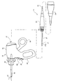
- FIG. 1 is a diagram showing a configuration of a surgical operation system according to an embodiment of the present invention.
- a surgical system 1 that is a medical device includes a handpiece 2, a main body device 3 that is an output control device, a foot switch 4, and a counter electrode plate 5.
- the handpiece 2 is a surgical treatment tool capable of both ultrasonic output and high-frequency current output.
- the handpiece 2 is connected to the main body device 3 via a detachable cable 2a.
- the handpiece 2 has an insertion portion 2b and a handle portion 2c.
- the main body device 3 as the control unit supplies at least one of a drive signal for ultrasonic output or a drive signal for high-frequency current output according to the setting.
- the main body device 3 has three output modes, that is, an ultrasonic output mode, a high frequency output mode, and a simultaneous output mode of ultrasonic and high frequency.
- the output mode is set by various operation buttons 3c provided on the main unit 3.
- the main unit 3 has a built-in speaker (not shown) for outputting sound or sound.
- the main unit 3 includes a plurality of display devices 3b and a plurality of various operation buttons 3c.
- the display 3b displays setting values and the like, and the various operation buttons 3c are buttons for setting various outputs and the like.
- the foot switch 4 is connected to the main body device 3 via the cable 4 a, and when the operator steps on the foot switch 4 with his / her foot, a predetermined operation signal FS is output and supplied to the main body device 3.
- the foot switch 4 is a switch for turning on or off the ultrasonic output at the time of ultrasonic output, and is a switch for turning on or off the high frequency output at the time of high frequency output.
- the output values of the ultrasonic vibration and the high-frequency current are set by operating the operation buttons on the operation panel of the main body device 3.
- the counter electrode plate 5 is connected to the main unit 3 via a cable 5a.
- the counter electrode plate 5 is a return electrode for returning the current flowing through the subject at the time of monopolar output of a high-frequency current.
- the surgeon can perform the operation, for example, under a laparoscope, holding the handpiece 2 in one hand and the other treatment tool in the other hand.
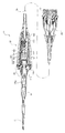
- FIG. 2 and 3 are diagrams showing the configuration of the handpiece 2 according to the present embodiment.
- FIG. 2 is a front view showing the configuration of the handpiece 2 according to the present embodiment.
- FIG. 3 is a diagram illustrating a state where two devices constituting the handpiece 2, that is, the first device 11 and the second device 12 are separated. As shown in FIG. 3, the handpiece 2 is configured by attaching the first device 11 to the second device 12.
- the first device 11 includes a probe 21 capable of transmitting ultrasonic vibrations, a substantially cylindrical grip portion 22 provided on the proximal end side of the probe 21, and a proximal end of the grip portion 22.
- This is a surgical treatment instrument having a cable 2a provided on the side and a connector portion 23 provided at the proximal end of the cable 2a.
- the probe 21 is a conductive shaft member that is connected to the grip portion 22 and can transmit at least one of ultrasonic vibration and high-frequency current.
- the distal end portion of the probe 21 is a treatment portion 21a having a spatula shape.
- the treatment portion 21a is a portion that is provided at the distal end portion of the probe 21 and transmits at least one of ultrasonic vibration and high-frequency current transmitted by the probe to the living tissue.
- An insulating sheath 24 is provided so as to cover the outer peripheral portion of the probe 21 from the distal end portion of the grip portion 22 to the vicinity of the distal end portion of the probe 21. However, the distal end portion of the probe 21 protrudes from the distal end opening of the insulating sheath 24.
- the connector unit 23 is configured to be detachable from the connector unit 3 a of the main body device 3.
- the plug in the connector part 23 engages with the receptacle of the connector part 3a.
- the configuration of the plug and receptacle will be described later.
- the first device 11 has a step portion 25 provided with a plurality of electrical contact pieces between the grip portion 22 and the insulating sheath 24.
- the step portion 25 is composed of a plurality of columnar step portions formed so that the diameter gradually decreases from the grip portion 22 toward the tip of the insulating sheath 24.
- the step portion 25 has a shape that can be engaged with the concave portion 41 of the second device so that the first device 11 can be attached to the second device 12.
- the recess 41 of the second device 12 is provided with a plurality of step portions on the inner peripheral portion so that the step portion 25 engages. That is, the concave portion 41 constitutes an attachment / detachment portion for detachably engaging the second device 12 with the first device 11.
- the first device 11 is also a surgical treatment tool capable of outputting an ultrasonic output, a high-frequency output, and simultaneous output of an ultrasonic wave and a high frequency, that is, a handpiece. A more detailed configuration of the first device 11 will be described later.
- the second device 12 includes an insertion portion 2b having a movable jaw 31 provided at the distal end, an operation portion main body 32 provided on the proximal end side of the insertion portion 2b, and a handle portion 2c provided on the operation portion main body 32. And have.
- the insertion portion 2b is a tubular member made of a conductive material whose outer peripheral surface is covered with an insulating layer, and is supported at the tip by a pin 2b1 and supported so as to be rotatable about the pin 2b1. It has a jaw 31.
- the rear end of the movable jaw 31 is connected to a drive shaft (not shown).
- the movable jaw 31 can be opened and closed in the vertical direction in FIGS. 2 and 3 via its drive shaft (not shown) in accordance with the operation of the handle portion 2c.
- a rotation knob 33 for rotating the insertion portion 2b about its axis is provided on the proximal end side of the insertion portion 2b.
- the rotary knob 33 is fixed to the outer periphery of the proximal end portion of the insertion portion 2b.
- the rotary knob 33 is not fixed to the operation unit main body 32 but is rotatably connected. Therefore, by rotating the rotary knob 33, the rotary knob 33 and the insertion portion 2b can be rotated around the longitudinal axis of the insertion portion 2b with respect to the operation portion main body 32.
- the operator can set the opening / closing direction of the movable jaw 31 to an arbitrary direction by rotating the rotation knob 33 around the axis of the insertion portion 2b.
- the handle portion 2 c includes a fixed handle 34 and a movable handle 35.
- the fixed handle 34 is formed integrally with the operation unit main body 32, and has a finger hooking hole 34a on which a plurality of fingers other than the operator's thumb can be hung.
- the movable handle 35 is pivotally supported around a pin 32 a provided on the operation unit main body 32 so as to be rotatable.
- the movable handle 35 has a finger hole 35a on which the operator's thumb can be hung.
- a proximal end portion of a drive shaft (not shown) connected to the rear end of the movable jaw 31 is connected to a portion of the movable handle 35 near the pin 32a.
- the second device 12 is configured to close the movable jaw 31 when the movable handle 35 is brought close to the fixed handle 34.
- the movement of the movable handle 35 around the pin 32a is converted into the movement of the movable jaw 31 around the support pin 2b1.
- the movable jaw 31 is indicated by a dotted line when it is closed, and is indicated by a solid line when it is open.
- the movable jaw 31 is a treatment part for sandwiching the biological tissue with the treatment part 21a, and the movable handle 35 brings the movable jaw 31 that is the treatment part close to the treatment part 21a to move the biological tissue. It is an operation part for pinching.
- the operation unit body 32 is provided with two switch buttons 36 and 37.
- the switch button 36 is a switch for turning on / off ultrasonic output or high-frequency current output.
- the switch 37 is a switch for changing the output value of the ultrasonic wave or the high frequency.
- the operation signals HS of the switch buttons 36 and 37 of the operation unit main body 32 are supplied to the main body device 3 via the corresponding sections 201b and 117b, the conduction member 188, and the signal line 2ab. Note that the switch buttons 36 and 37 may function as switches for only high-frequency output, and ultrasonic output may be performed by the foot switch 4.
- the ultrasonic output or the high-frequency current output and the change of the output value may be performed not only by the two switches of the operation unit main body 32 but also by the various switches 3c of the main body device 3.
- the setting of the output mode or the like may be performed not only by the various switches 3 c of the main body device 3 but also by two switches of the operation unit main body 32.
- a recess 41 is formed as an attachment / detachment unit for detachably engaging the first device 11.
- the second device 12 has an insertion channel 42 into which the tip of the probe 21 of the first device 11 is inserted from the recess 41 and the insulating sheath 24 can be inserted.
- the recess 41 is formed so that the step portion 25 of the first device 11 is engaged.
- the first device 11 When the first device 11 is attached to the second device 12 so that the stepped portion 25 engages with the recess 41, the first device 11 and the second device 12 are coupled, and the first device 11
- the treatment portion 21a at the distal end portion of the probe 21 protrudes from the insertion portion 2b of the second device 12 so as to be able to be clamped with the movable jaw 31 of the second device.
- a treatment portion that can be sandwiched between the distal end portion of the probe 21 and the movable jaw 31 is formed, and a plurality of electrical contact pieces provided on the step portion 25
- the plurality of electrical contact pieces provided in the recess 41 are electrically connected to each other with contact pieces corresponding to each other. The electrical connection will be described later.
- the surgeon attaches the second device 12 to the first device 11, and after the treatment using the scissors-shaped handpiece 2, from the trocar provided on the body wall of the subject. Pull out the handpiece 2.
- the surgeon removes the second device 12 from the first device 11, inserts the first device 11 into the trocar, and then performs a procedure using the spatula-shaped first device 11 as a handpiece. be able to.
- the surgeon pulls out the first device 11 from the trocar provided on the body wall of the subject and attaches the second device 12.
- the first device 11 to which the second device 12 is attached can be inserted into the trocar, and then a treatment using the scissor-shaped handpiece 2 can be performed.
- the main body device 3 outputs a bipolar output when the connected treatment instrument is used as, for example, a scissors-shaped high-frequency treatment instrument, and is used as a spatula-shaped high-frequency treatment instrument. If so, output a monopolar output. Further, the main body device 3 changes the output value in the case of the scissors-shaped ultrasonic treatment tool and in the case of the spatula-shaped ultrasonic treatment tool based on the detection result.
- FIG. 4 is a cross-sectional view of the first device 11.
- FIG. 4 is a cross-sectional view seen from above to show that the tip of the probe 21 has a spatula shape.
- FIG. 5 is a cross-sectional view of the grip portion 22 of the first device 11.
- the treatment portion 21a at the distal end portion of the probe 21 is substantially straight in FIGS. 2 and 3, but since FIG. 4 is a cross-sectional view seen from the upper surface, the distal end portion is bent into a spatula shape in FIG. 6 to 9 are cross-sectional views of the grip portion 22.
- 4 and 5 are sectional views taken along line AA in FIGS.
- FIG. 6 is a cross-sectional view taken along line VI-VI in FIG.
- FIG. 7 is a sectional view taken along line VII-VII in FIG.
- FIG. 8 is a cross-sectional view taken along line VIII-VIII in FIG.
- FIG. 9 is a sectional view taken along line IX-IX in FIG.
- the first device 11 is also a surgical treatment tool that can be used alone as a handpiece.
- the gripping unit 22 includes the ultrasonic vibration unit 101.
- the ultrasonic transducer unit 101 is configured in a cylindrical shape in which a plurality of piezoelectric elements 102 formed in a donut shape are stacked with a plurality of annular electrodes 103 disposed between adjacent piezoelectric elements. Having a vibrating block. Further, a bolt 104 is passed through a central through hole of the plurality of stacked piezoelectric elements 102 and the plurality of electrodes 103, and the bolts 104 are screwed into the horn part 105, thereby the plurality of piezoelectric elements 102 and the plurality of electrodes.
- the ultrasonic transducer unit 101 is configured such that 103 is firmly attached.
- the ultrasonic transducer unit 101 is a unit of a Langevin type bolted ultrasonic transducer.
- the ultrasonic transducer unit 101 is disposed in a cylindrical casing 111.
- the plurality of signal lines of the plurality of electrodes 103 are connected to a part of the plurality of signal lines 2ab in the cable 2a via the connector 112 at the base end portion of the casing 111.
- the tip side of the horn part 105 is the probe 21, and the part 105a from the horn part 105 to the probe constitutes an active line for high frequency output.
- a flange portion 105 a is formed at the proximal end portion of the horn portion 105.
- An inward flange portion 111 a is formed at a predetermined position on the inner periphery of the casing 111.
- a female threaded portion 111 b is formed on the inner peripheral surface of the tip portion of the casing 111.
- the horn portion 105 is fixed to the casing 111 by the cylindrical fixing member 113.
- a male screw portion 113 a is formed on the outer peripheral portion of the fixing member 113, and the male screw portion 113 a is screwed into the female screw portion 111 b of the casing 111, whereby the fixing member 113 is connected to the horn from the front end side of the casing 111.
- the part 105 is pressed. Thereby, the horn part 105 is fixed inside the casing 111.
- a packing 114 made of a rubber material is provided between the base end portion of the fixing member 113 and the flange portion 105a.
- an O-ring 115 is provided on the outer peripheral portion of the fixing member 113. The packing 114 and the O-ring 115 prevent water, blood, etc. from entering the casing 111.
- a cylindrical cap member that is, a front end cap 116 is attached to the front end side of the casing 111.
- An O-ring 116 a is provided on the inner peripheral surface of the tip cap 116 so as to be in close contact with the horn portion 105.
- the tip end side of the tip cap 116 forms a stepped portion 25, and a plurality of electrical contact pieces 117 are provided on the stepped portion 25.
- Three contact pieces 117a, 117b, and 117c are provided on three step portions on the outer peripheral surface of the tip cap 116, respectively, and one contact piece 117d is provided on the inner peripheral surface.
- a connection detection contact piece 117a to which a signal line for detecting the connection of the second device 12 is connected in order from the distal end side of the distal end cap 116, an active line
- an active line contact 117b connected to the signal line for use and a common contact 117c connected to the signal line for the common line of the switch signal.
- a recovery line contact piece 117 d is provided on the inner peripheral surface of the tip cap 116.
- the contact piece 117d is exposed on the surface of the inner peripheral surface of the tip cap 116, and is provided inside the step portion 25 so that the conductive member of the second device 12 can come into contact as will be described later. .
- the section 117a includes two sections.
- electrical conduction is formed between the two sections.
- the main device 3 detects the conduction state. That is, the intercept 117a and the signal line 2ab constitute a connection signal output unit capable of outputting a connection signal DS indicating that the second device 12 is connected to the first device 11.
- the main unit 3 changes the high frequency output in the case of high frequency output from monopolar output to bipolar output, and in the case of ultrasonic output, the ultrasonic output is converted to an ultrasonic wave in the shape of a spatula. Change the output value to the ultrasonic output value for scissors shape.
- the three contact pieces 117a, 117b, 117c are formed in an annular shape along the outer peripheral surface of the step portion 25.
- the contact piece 117d is provided in an annular shape along the inner peripheral surface of the tip cap 116.
- the contact piece 117d is in contact with an electrical contact piece (not shown) in the second device 12 described later.
- the tubular member 202 (FIG. 14) made of a conductive material in the second device 12 is electrically connected to the tubular member made of a conductive material in the insertion portion 2b. Therefore, the contact piece 117d is a collection line contact piece connected to a collection line signal line at the time of high-frequency output.
- Each contact piece is connected to a corresponding wire of the wire 2ab in the cable 2a via a conductive member 118 passing through the inside of the tip cap 116 made of an insulating member and a wire 119 connected to the conductive member.
- the conducting member 118 passing through the tip cap 116 is provided in the tip cap 116 by insert molding.
- An O-ring 120 is provided on the outer periphery of the tip cap 116.
- the casing 111 to which the tip cap 116 is attached is provided so as to be inserted into the second casing 121.
- the second casing 121 is a cylindrical member whose diameter decreases from the distal end side toward the proximal end side.
- the O-ring 120 is in close contact with the inner peripheral surface of the second casing 121, and the first casing 111 and the tip cap 116 are disposed in the second casing 121.
- a male screw part 121 a is formed on the outer peripheral surface on the distal end side of the second casing 121.
- a male screw part 121 b is also formed on the outer peripheral surface on the proximal end side of the second casing 121.
- the second casing 121 is further provided in the third casing 122.
- the third casing 122 is also a cylindrical member whose diameter decreases from the distal end side toward the proximal end side.
- On the outer peripheral surface of the third casing 122 a plurality of convex portions 122a are formed for improving the graspability by the operator.
- the fixing ring 123 and the end cap 124 are fixed so as to sandwich the third casing 122.
- the fixing ring 123 is a cylindrical member made of an insulating member, and has an inward flange portion on the distal end side.
- a female thread portion 123 a is formed on the inner peripheral surface of the base end side of the fixing ring 123.
- the end cap 124 is a cylindrical cap member made of an insulating member, and has a step portion on the outer peripheral portion on the distal end side.
- a female threaded portion 124 a is formed on the inner peripheral surface on the distal end side of the end cap 124.
- the ultrasonic transducer unit 101 is disposed in the grip portion 22.
- the ultrasonic transducer unit 101 When the first device 11 is in the ultrasonic output state, the ultrasonic transducer unit 101 generates heat. As a result, due to the continuous ultrasonic output, the heat generated in the ultrasonic transducer unit 101 conducts heat through the casing of the grip portion 22, and the temperature of the outer peripheral portion of the grip portion 22 increases. Heating of the gripping part 22 during the operation may cause a decrease in operability of the handpiece 2. Therefore, in the first device 11 of the present embodiment, an air layer is provided between the casings of the gripping portion 22 in order to prevent the gripping portion 22 from becoming hot.
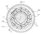
- a plurality of grooves 125 (125a, 125b, 125c) extending along the axial direction of the casing 111 are formed in the outer peripheral portion of the first casing 111.
- One groove 125a is a positioning groove with respect to the second casing 121, and a portion protruding toward the inner peripheral side of the second casing 121 is fitted into the groove 125a, so that the first casing 111 and the first casing Appropriate positioning with the second casing 121 is performed.
- the four grooves 125b are grooves through which the conducting member 118 in the tip cap 116 is passed.
- the four grooves 125 c are grooves for forming an air layer between the first casing 111 and the second casing 121.
- the gripping portion 22 of the first device 11 is configured by using three casings 111, 121, and 122. Since the air layer provided positively as described above is provided between the first casing 111 and the second casing 121, a large heat insulating effect can be obtained. Furthermore, since an air layer is formed by a gap between the second casing 121 and the third casing 122, the heat insulating effect is further increased.
- casings In this embodiment, three casings are used, but four or more casings may be used to positively provide the air layer as described above between adjacent casings.
- an air layer is provided between the casings inside the gripping portion 22 (between the first casing 111 and the second casing 121 in the present embodiment), and the outermost casing (the third casing in the present embodiment). 122), when the outermost casing 122 is molded and manufactured, the effect of increasing the degree of freedom of the outer shape of the outermost casing 122 is also produced. By increasing the degree of freedom of the outer shape of the casing 122, it is possible to make the grip portion 22 more excellent in gripping property.
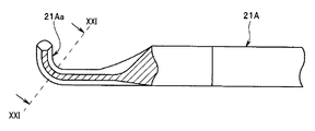
- the probe 21 described above has a spatula shape as shown in FIG. 4, but may have a hook shape as shown in FIG.
- FIG. 10 is a cross-sectional view seen from the upper surface of the probe 21A having a hook portion at the tip.
- the hook portion of the probe 21 ⁇ / b> A has an S shape so that the insertion channel 42 of the second device 12 can be inserted.
- the inside of the S-shaped hook-shaped portion is a protruding portion, that is, an edge portion having a predetermined cross-sectional shape.
- each component of the first device 11 and the second device 12 is made of a material that is compatible with high-temperature and high-pressure steam sterilization, that is, autoclave processing, such as super engineering plastics.
- each component may be a normal resin material component.
- FIG. 11 is a front view of the plug 151 in the connector portion 23.
- FIG. 12 is a front view of the receptacle 161 in the connector portion 3a.
- FIG. 13 is a cross-sectional view taken along line XIII-XIII in FIGS. 11 and 12 for explaining the connection between the plug 151 and the receptacle 161.
- the connector part 23 of the first device 11 has a plug 151. As shown in FIGS.
- the plug 151 has a cylindrical portion 153 provided with a central axis in a direction orthogonal to the plane of the base portion 152. Further, the plug 151 has two protruding portions 154 and 155 protruding from the base portion 152.
- the first protrusion 154 has a plurality of output terminals 154a for driving signals
- the second protrusion 155 has a second protrusion 155 having a plurality of terminals 155a for switch signals and connection detection signals. Have.
- Each of the plurality of terminals 154a and 155a is connected to a corresponding signal line of the signal line 2ab in the cable 2a.
- the first protrusion 154 and the second protrusion 155 are formed inside the cylindrical part 153. Further, around the cylindrical portion 153, a plurality of claw portions 153a that are engaged with engaging portions 163a (FIG. 12) provided in predetermined portions of the connector 3a are formed.
- the connector 3a has a receptacle 161.
- the receptacle 161 has a cylindrical portion 163 provided with a central axis in a direction orthogonal to the plane of the base portion 162.
- the receptacle 161 has a protruding portion 164 protruding from the base portion 162.
- the protrusion 164 has two recesses 165 and 166.
- the two concave portions 165 and 166 are formed from the front end side of the protruding portion 164 toward the base portion 162.
- the protruding portion 164 is formed inside the cylindrical portion 163.
- a plurality of engaging portions 163 a that engage with the plurality of claw portions 153 a are provided on the inner peripheral portion of the cylindrical portion 163.
- the recess 165 has a plurality of output terminals 165a for driving signals on its inner peripheral surface
- the recess 166 has a plurality of terminals 166a for switch signals and connection detection signals on its inner peripheral surface.
- Each terminal 165a, 166a is connected to a corresponding circuit of the main unit 3 by a corresponding signal line.
- a groove portion 154b having a semicircular cross section is formed in the protruding portion 154 of the plug 151 so that the plug 151 is inserted in the correct orientation with respect to the receptacle 161.
- the groove part 154 b is formed in parallel to a direction orthogonal to the plane of the base part 152.
- a semi-cylindrical convex portion 165b that engages with the groove portion 154b is formed on the inner peripheral portion of the concave portion 165 of the receptacle 161. Accordingly, the plug 151 is inserted in the correct orientation with respect to the receptacle 161 only when the semi-cylindrical convex portion 165b fits into the groove portion 154b of the plug 151, and the connector portion 23 is attached to the connector portion 3a. be able to.
- the plug 151 although not shown, an identification element for identifying the type of the first device 11, for example, a resistor is provided.
- a resistor (not shown) is connected to the two terminals 155a for connection detection.
- the plug 151 is attached to the receptacle 161
- the two terminals 155a and the corresponding two terminals 166a on the receptacle 161 side are electrically connected, and the main device 3 is connected to the connection of the first device 11.
- the type of the first device 11 can be detected.
- the resistor instead of the resistor, only the wiring connecting the two terminals 155a for connection detection may be used. In that case, the main device 3 can detect the connection or non-connection of the device.
- the plug 151 may not be properly engaged with the receptacle 161.
- the plug 151 when the plug 151 is in a state where it is not detached from the receptacle 161, there may be a state where a gap is formed between the output terminals of the drive signal.
- the arrangement of the terminals in the plug 151 and the terminals in the receptacle 161 is devised. As shown in FIG. 13, when the connector portion 23 is attached to the connector portion 3a, the plug 151 moves relative to the receptacle 161 in the attachment direction indicated by the arrow AA.
- a plurality of terminals 165a for switch signals and connection detection signals are arranged on the outer peripheral portions of the protrusions 154 and 155.
- the position S1 at which the plurality of output terminals 154a first contact the plurality of output terminals 164a is a distance d from the base portion 152 than the position S2 at which the plurality of terminals 155a first contacts the plurality of terminals 165a. is seperated.
- the distance d is, for example, 0.8 mm.
- the first device 11 has the plug 151 as a connector part for connecting to the main unit 3, and the main unit 3 has the receptacle 161 as a connector to which the plug 151 is connected.
- the plug 151 and the receptacle 161 are connected along a predetermined connection direction, after the contact pieces that supply the drive signal to the plug 151 come into contact with each other, the contact that transmits the instruction signal that instructs the output of the drive signal is transmitted.
- the contact piece for supplying the drive signal is arranged at a position displaced along the connection direction with respect to the contact piece for transmitting the instruction signal so that the pieces come into contact with each other.
- FIG. 14 is a cross-sectional view of the second device 12.
- Three electrical contact pieces 201 a, 201 b, 201 c are provided on the inner peripheral surface of the recess 41 of the operation unit main body 32.
- the three contact pieces 201a, 201b, and 201c are sections corresponding to the three contact pieces 117a, 117b, and 117c of the first device 11, respectively.
- the three contact pieces 201a, 201b, and 201c are in contact with the three contact pieces 117a, 117b, and 117c of the first device 11, respectively.
- a tubular member 202 whose central axis is coaxial with the axis of the insertion portion 2 b is provided in the operation portion main body 23.
- the tubular member 202 is made of a conductive material.
- a notch (not shown) is formed on the proximal end side of the tubular member 202.
- the second device 12 has a step portion 25. Is configured to engage with the recess 41.
- the inside of the tubular member 202 and the inside of the insertion portion 2 b form the insertion channel 42.
- a spring member 203 is provided on the outer peripheral portion of the tubular member 202 via a tubular member 204. Specifically, the tubular member 202 is inserted through a tubular member 204 made of an insulating material, and the tubular member 204 is inserted inside the spring member 203. A flange portion 204 a is formed on the outer peripheral portion of the tubular member 204. The distal end side of the spring member 203 is in contact with the flange portion 204a via the spring receiving member 203a. The proximal end side of the spring member 203 abuts on the vicinity of the pin 32 a of the movable handle 35, and the spring member 203 is provided in the operation portion main body 32 so as to press the movable handle 35.
- the spring member 203 is a constant force that urges the handle 35 with a constant force in a direction in which the movable handle 35 is separated from the fixed handle 34, in other words, in a counterclockwise direction around the pin 32a in FIG. It is a spring. That is, the spring member 203 constitutes an urging means for urging the movable handle 35 so as to rotate the handle portion 2c in the opening direction with the pin 32a as the rotation center.
- the distal end portion of the tubular member 202 is electrically connected to the insertion portion 2b.
- the tubular member 202 is electrically connected to the contact piece 117d exposed on the surface of the step portion 25 of the first device 11 when the first device 11 and the second device 12 are coupled. Is formed. Therefore, the movable jaw 31, the insertion portion 2b, the tubular member 202, the contact piece 117d, the conducting member 118, and the cable 2a constitute a recovery line during bipolar output of high frequency output.
- the switches 36 and 37 are connected to the active line contact piece 201b and the common line contact piece 201c via the circuit board 211 and the signal line 212 of the operation unit main body 32. Therefore, for example, when the surgeon presses the switch 36 with the thumb during high-frequency output, a switch signal for outputting a high-frequency output from the probe 21 is sent to the contact pieces 201b and 117b, the conductive member 118, and the cable 2a. To the main device 3. Therefore, when the switch 36 is pressed, the probe 21 outputs a high frequency output. When the switch 37 is pressed, the probe 21 changes the output value of the high frequency output.
- FIG. 15 is a front view according to a modification of the second device of the present embodiment.
- the above-described handpiece 2 is for so-called laparoscopic operation, but the second device 12A shown in FIG. 15 is a device for constituting a handpiece for open surgery.
- the second device 12A according to this modification includes a cylindrical portion 251 having a tapered portion on the distal end side, a tubular portion 252 provided at the distal end portion of the cylindrical portion 251 and a pin provided on the outer peripheral portion of the tubular portion 252. And a movable member 254 supported by the shaft 253.
- a fixed handle 251b having a finger hole 251a through which an operator's finger is hung is provided on the outer peripheral portion of the cylindrical portion 251.
- the opening 41 ⁇ / b> A at the base end of the cylindrical portion 251 is an opening for inserting the first device 11 from the probe 21.
- the treatment portion 21 a of the probe 21 of the first device 11 inserted from the cylindrical portion 251 protrudes from the distal end portion of the cylindrical portion 251.
- a movable handle 254b having a finger hooking hole 254a on which the operator's thumb is hung is provided on the proximal end side of the movable member 254.
- a movable jaw 31 ⁇ / b> A is provided on the distal end side of the movable member 254.
- the inner peripheral surface of the opening 41A of the cylindrical portion 251 of the second device 12A has a shape corresponding to the stepped portion 25 and a plurality of electrical contact pieces, similarly to the second device 12 described above.
- the surgeon operates the movable handle 254b, thereby operating the movable jaw 31A and the treatment portion 21a at the distal end portion of the probe 21. Can be opened and closed.
- switches 36 and 37 are provided on the operation unit main body 32.
- two switches (not shown) corresponding to the switches 36 and 37 may be provided on the outer peripheral portion of the grip portion 22 of the first device 11.
- the switch corresponding to the switch 36 for high-frequency output is connected to the first device 11 in a state where the first device is attached to the second device.
- the operation unit may be provided at a position where the movable handle 254b contacts. That is, a switch for giving an instruction to output at least one of ultrasonic vibration and high-frequency current is provided on the grip portion 22, and the switch is an operation portion that is a grip portion when the second device 12B is attached. You may make it arrange
- FIG. 16 is a diagram for explaining a modification in the case where a switch is provided at a position where the movable handle of the first device comes into contact.
- the first device 11A is provided with a switch 36A on the side surface of the grip portion 22 at a position where the movable device 254b comes into contact when the movable device 254b is closed when the first device 11A is attached to the second device 12B. Therefore, as shown in FIG. 16, a notch 251Aa is partially formed at the base end of the cylindrical portion 251A so that the switch 36A is exposed.
- the operator can give an instruction to output a high-frequency output only by closing the movable handle 254b, so that the operability is good.
- the switch for high-frequency output with a free finger there is no need to turn on the switch for high-frequency output with a free finger, and the treatment part at the tip of the handpiece will fluctuate. There is no such thing.
- the switch 36A is preferably a two-stage switch.
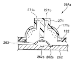
- FIGS. 17 to 19 are diagrams for explaining the configuration of the switch 36A of the two-stage switch provided in the first device. 17 and 18 are cross-sectional views for explaining the configuration of the switch 36A.
- the switch 36A is provided on the surface of the casing 122 of the grip portion 22 so that a substantially conical pressing member 261 made of a rubber member or the like and having a flat portion 261a flat at the tip protrudes.
- a protruding portion 261b is formed on the inner side of the pressing member 261, that is, on the back side of the flat portion 261a.
- a conductive metal member 261c is provided at the tip of the protrusion 261b. The metal member 261c is connected to a wiring (not shown).
- a substrate 262 is disposed inside the casing 122.
- a disk member 263 made of a conductive metal material is provided at a position on the substrate 262 facing the protruding portion 261b.
- the disc member 263 is not a flat member, but has a shape that curves along the surface of the sphere, and the center portion projects in the direction of the projecting portion 261b.
- the disk member 263 is connected to the wiring 262a on the substrate 262, and a contact point 262b connected to a wiring (not shown) is provided on the substrate 263 below the disk member 263.
- the pressing member 261 Since the pressing member 261 is made of a rubber member or the like, it is deformed when pressed from above. As shown by the dotted line in FIG. 17, when the pressing member 261 is deformed, the metal member 261 c at the tip of the protruding portion 261 b comes into contact with the disc member 263. Due to this contact, the wiring connected to the metal member 261c and the wiring 262a of the disk member 263 are electrically conducted, so that the main body device 3 can detect the conduction. When the main body device 3 detects the contact between the metal member 261a and the disk member 263, the main body device 3 outputs a sound for notifying the operator of the contact with sound (hereinafter referred to as a first sound) via a speaker.
- a sound for notifying the operator of the contact with sound hereinafter referred to as a first sound
- the main body device 3 detects the continuity, and outputs a sound for notifying the operator of the contact through a speaker as a second sound different from the first sound, and generates a high-frequency current. Start output. The second sound is output while the central portion of the disk member 263 is in contact with the contact point 262b on the substrate.
- the switch 36A is a two-stage switch that outputs an electrical switch signal in the first and second stages.
- the operator can recognize that the handle is closed so as to close the handle portion by the first sound, and the high-frequency output is started by the second sound. Can be recognized.
- the main body device 3 is notified by the first sound that the handle portion has been grasped and is made capable of high-frequency output thereafter, the surgeon can reliably perform the high-frequency output operation. it can.
- FIG. 19 is a cross-sectional view showing a modification of the switch 36A.
- the switch shown in FIG. 19 is also a two-stage switch, but the first stage is a switch that generates mechanical sound.
- symbol is attached
- the switch 36 ⁇ / b> Aa is provided on the surface of the casing 122 of the grip portion 22 so that a substantially cone-shaped pressing member 271 made of a thin metal or the like and having a flat flat portion 271 a at the tip protrudes. It has been.
- a protruding portion 271b is formed on the inner side of the pressing member 271, that is, on the back side of the flat portion 271a.
- the side surface portion 271c of the pressing member 271 has a shape that slightly bulges outward as shown by the solid line in FIG.
- the side surface portion 271c is deformed so as to suddenly dent in at a certain point as shown by a dotted line in FIG. It has a shape. A mechanical sound is generated when the side surface portion 271c is momentarily deformed.
- the main body device 3 detects the conduction.
- the main unit 3 outputs a sound for notifying the operator of the contact via the speaker and starts outputting a high-frequency current. This sound is output while the central portion of the disk member 263 is in contact with the contact point 262b on the substrate.
- the switch 36Aa is a two-stage switch that generates mechanical sound at the first stage and outputs an electrical switch signal at the second stage. As described above, by using the two-stage switch as described above, the surgeon can reliably operate the high-frequency output.
- the handpiece 2 can simultaneously output an ultrasonic output and a high-frequency output.
- the treatment portion 21a of the spatula-shaped probe 21 may be used for ultrasonic output, for high-frequency output, or for simultaneous output of ultrasonic and high-frequency.
- the probe 21 may constitute a scissors-shaped treatment portion in cooperation with the movable jaw 31.
- the movable jaw 31 and the treatment portion 21a of the probe 21 may be used for ultrasonic output, used for high-frequency output, or used for simultaneous output of ultrasonic and high-frequency. Therefore, the treatment portion 21a and the jaw member 31 have appropriate shapes corresponding to such usage patterns.
- the jaw member 31 has a groove 311 in which a part of the insertion portion probe 21 is engaged along the axial direction.
- the groove 311 has a channel shape with a wide opening in a cross section orthogonal to the axis of the jaw member 31.
- the jaw member 31 is a conductive material, but the insulating member 312 is provided in a range where the treatment portion 21a contacts the channel-shaped bottom surface portion 313 along the axial direction.
- the treatment portion 21a has a rhombus shape with a part cut off in a cross section orthogonal to the axial direction.
- the cross-sectional shape of the treatment portion 21a is a shape cut in a direction orthogonal to the longer diagonal of the rhombus.
- the treatment portion 21 a from which a part of the rhombus is cut off has a trapezoidal shape portion 321 that engages with the groove 311 of the jaw member 31.
- a portion where a part of the rhombus is not cut out is an isosceles triangle portion 322 of a substantially isosceles triangle of the treatment portion 21a.
- the treatment portion 21a and the jaw member 31 are fitted.
- the bottom surface portion 313 of the channel-shaped groove 311 abuts on the top surface portion 323 of the trapezoidal shape portion 321 of the treatment portion 21a, and the two inner wall portions 314 of the channel-shaped groove 311 are in contact with the trapezoidal shape portion 321. It abuts on the slope portion 324.
- the apex angle part 325 of the isosceles triangle part 322 of the treatment part 21a is rounded, the apex angle part 325 has a slightly sharp angle.
- the entire treatment portion 21a acts as an ultrasonic vibration treatment portion, and in particular, the apex portion 325 and its peripheral portion (shown by dotted lines) Acts like a scalpel on the tissue to be treated.
- the apex angle portion 325 and its peripheral portion act as an electric knife on the tissue to be treated.
- the bottom surface portion 313, the inner wall portion 314, the top surface portion 323, and the slope portion 324 act as an action surface for ultrasonic vibration.
- the inner wall portion 314 and the inclined surface portion 324 act as a working surface for bipolar high-frequency current.
- the entire treatment portion 21a acts as an ultrasonic vibration treatment portion, and in particular, the apex angle portion 325 and its peripheral portion ( (Shown by a dotted line) acts like an electric knife on the tissue to be treated.
- the handpiece 2 is used as a treatment tool for simultaneous output of scissors-shaped ultrasonic waves and high frequencies
- the bottom surface portion 313 and the top surface portion 323 act as an action surface for ultrasonic vibration
- the portion 324 functions as a working surface for bipolar high-frequency current.
- the first device 11 is used as an ultrasonic treatment instrument or a high-frequency treatment instrument, but also the first device 11 and the second device 12 are connected.
- the first device 11 and the second device 12 are connected to each other, and treatment at the time of simultaneous output of scissors-shaped ultrasonic waves and high frequencies is performed. Even when used as a tool, operability is good.
- a bipolar output is used as a high frequency output.
- monopolar output may be possible.
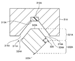
- FIG. 21 is a diagram for explaining the configuration of the treatment section in the case of the hook-shaped probe 21A.
- FIG. 21 is a cross-sectional view of the treatment portion 21Aa and the jaw member 31A along the line XXI-XXI in FIG.
- FIG. 10 shows only the treatment portion 21Aa, but FIG. 21 shows a cross section of the treatment portion 21Aa and the jaw member 31A in the case of a scissors-shaped treatment tool.
- the jaw member 31A has a groove 311A in which a part of the treatment portion 21Aa is engaged along the axial direction.
- the groove 311A has a channel shape with a wide opening in a cross section orthogonal to the axis of the jaw member 31A.
- the jaw member 31A is a conductive material, but an insulating member 312A is provided on the channel-shaped bottom surface portion 313A along the axial direction.
- the treatment portion 21Aa has a rhombus shape with a part cut off in a cross section orthogonal to the axial direction.
- the cross-sectional shape of the treatment portion 21Aa is a shape in which a part of the rhombus is cut out in a direction orthogonal to one diagonal line, as shown in FIG.
- the treatment portion 21Aa from which a part of the rhombus is cut off has a trapezoidal shape portion 321A that engages with the groove 311A of the jaw member 31A.
- a portion of the rhombus that is not cut out is an isosceles triangular portion 322A of the probe 21A.
- the treatment portion 21Aa and the jaw member 31A are fitted.
- the bottom surface portion 313A of the channel-shaped groove 311A abuts on the upper surface portion 323A of the trapezoidal shape portion 321A of the treatment portion 21Aa, and the two inner wall portions 314A of the channel-shaped groove 311A are formed on the trapezoidal shape portion 321A. It abuts on the slope portion 324A.
- the apex angle portion 325A of the isosceles triangle portion 322A of the treatment portion 21Aa is rounded, but the apex angle portion 326 inside the hook shape has a slightly sharp angle.
- the angle ⁇ of the apex portion 326 is preferably 45 degrees to 100 degrees. 45 degrees is the intensity limit of the probe 21A.
- the apex angle portion 326 of the treatment portion 21Aa constitutes a protruding portion, that is, an edge portion having a predetermined angle inside the hook-shaped portion.
- a hook-shaped treatment portion is often used for incision.
- the apex angle portion 326 of the probe 21A serves as an action portion during incision. Since the apex angle portion 326 has a slightly sharp angle ⁇ , it is effective for an incision procedure.
- the treatment section 21Aa and the jaw member 31A shown in FIG. 21 are the treatment section shown in FIG. 20 at the time of ultrasonic output, high-frequency output, and simultaneous output of ultrasonic and high-frequency, respectively, except for the action at the time of incision. The same action as 21a and the jaw member 31 is performed.
- FIG. 22 is a block diagram illustrating the configuration of the main device 3.
- the main unit 3 is a control unit that controls output of a drive signal for supplying at least one of ultrasonic vibration and high-frequency current to the first device 11.
- the main body device 3 includes an ultrasonic output control unit 51, a high frequency output control unit 61, and a switching control unit 71.
- the ultrasonic output control unit 51 includes a control circuit 52 and an output circuit 53 that outputs a drive signal for ultrasonic vibration.
- the high frequency output control unit 61 includes a control circuit 62 and an output circuit 63 that outputs a drive signal for high frequency current output.
- the control circuits 52 and 62 are composed of various circuits such as a CPU and a memory.
- the control circuits 52 and 62 are connected to the display 3b and the operation button 3c of the main unit 3.
- An operation signal FS from the foot switch 4 and an operation signal HS of the switches 36 and 37 of the handpiece 2 are input to the control circuits 52 and 62.
- a connection signal DS is input to the switching control unit 71.
- the switching control unit 71 supplies an output control signal to the control circuits 52 and 62 based on the connection signal DS.
- the intercept 117a and the signal line 2ab constitute a connection signal output unit capable of outputting a connection signal DS indicating that the second device 12 is connected to the first device 11.
- the output circuit 53 supplies a drive signal DR1 for ultrasonic vibration to the first device 1.
- the output circuit 63 supplies a drive signal DR2 for outputting a high-frequency current to the first device 1.
- the control circuits 52 and 62 supply output control signals CS1 and CS2 to the output circuits 53 and 63, respectively, based on the setting in the operation button 3c and the operation signals from the foot switch 4 and the switches 36 and 37.
- the output circuits 53 and 63 output drive signals DR1 and DR2 based on the output control signals CS1 and CS2, respectively.
- the main body device 3 outputs to the handpiece 2 or the first device 11 a drive signal for outputting an ultrasonic output, a high-frequency output, or simultaneous output of an ultrasonic wave and a high frequency, according to the setting and the operation signal. .
- the main unit 3 when only the first device 11 is connected, the main unit 3 has three modes: an ultrasonic output mode, a high frequency output mode, and a simultaneous output mode of ultrasonic and high frequency. Further, in the case of the handpiece 2 in which the first device 11 is mounted on the second device 12, the main body device 3 has an ultrasonic output mode, a high-frequency output mode of bipolar output, and an ultrasonic and bipolar output (or monopolar output). 3 modes of high-frequency simultaneous output mode).
- the main body device 3 controls the output of a drive signal for supplying at least one of ultrasonic vibration and high frequency current to the first device 11 based on the connection signal DS. That is, for example, during operation, when the main body device 3 detects that the first device 11 is connected to the concave portion 41 that is the attachment / detachment portion of the second device based on the connection signal DS,
- the output of the drive signal DR2 is controlled so as to switch to bipolar output (or monopolar output), and in the case of output of ultrasonic vibration, the drive signal is switched so as to switch to ultrasonic drive output suitable for treatment by the scissors-shaped treatment section. Controls the output of DR1.
- the main unit 3 detects that the first device 11 is removed from the recess 41 of the second device based on the connection signal DS, the main unit 3 is driven so as to switch to the monopolar output when the high-frequency current is output.
- the output of the drive signal DR1 is controlled so as to switch to the ultrasonic drive output suitable for the treatment by the spatula-shaped treatment unit.
- the main body device 3 when the main unit 3 detects that the first device 11 is connected to the recess 41 of the second device 12 based on the connection signal DS, the main body device 3 simultaneously outputs ultrasonic vibration and high-frequency current.
- the outputs of the drive signals DR1 and DR2 are controlled so as to switch between simultaneous output of ultrasonic vibration and bipolar output (or monopolar output) high-frequency current suitable for treatment by the scissors-shaped treatment section.
- the main unit 3 detects that the first device 11 has been removed from the recess 41 of the second device 12 based on the connection signal DS, the ultrasonic wave drive suitable for treatment by the spatula-shaped treatment unit
- the drive signals DR1 and DR2 are switched so as to switch between the ultrasonic vibration output of the output, the high-frequency current output of the monopolar output, or the simultaneous output of the ultrasonic vibration suitable for the treatment by the spatula-shaped treatment unit and the high-frequency current of the monopolar output. Control the output.
- the main body device 3 can automatically control the output of the drive signal for supplying at least one of the ultrasonic vibration and the high-frequency current to the first device 11 based on the connection signal DS. it can.
- the main unit 3 automatically changes the output, for example, changes between bipolar and monopolar, or changes the output value of the ultrasonic output.
- a predetermined lamp is turned on to notify the surgeon of the connection status of the first device 11 and the second device 12, and the surgeon switches the output. May be performed using an operation button or the like of the main unit 3.
- the handpiece 2 can output both high-frequency output and ultrasonic output individually or simultaneously
- the output switching control of the present embodiment is limited to high-frequency output.
- the present invention can also be applied to a handpiece capable of performing only an ultrasonic output or a possible handpiece.
- the main unit 3 determines that the high-frequency output is a monopolar output and the first device is a second device based on the connection signal DS. The output is switched so that the high frequency output is a bipolar output.
- the main body device 3 uses the first signal suitable for the spatula-shaped treatment unit based on the connection signal DS.
- the output is switched so that the ultrasonic output is output at the second set value suitable for the scissors-shaped treatment section.
- a surgical treatment tool of a type that clamps and treats a living tissue and a surgical treatment tool of a type that treats by contacting the living tissue can be realized.
- the time required for changing the treatment tool during surgery is shorter because the burden on the patient is reduced.
- the surgeon instructs the nurse, etc., gives the treatment tool that has been used to the nurse, etc., and the nurse removes the treatment tool from the control device and uses it for the surgeon.
- the series of operations described above for handing over a treatment tool is complicated and takes time.
- the high-frequency treatment tool proposed in the above Japanese Patent Application Laid-Open No. 2009-78155 is a forceps having a structure in which an extension part of a monopolar element is provided at one end part of two members of a bipolar forceps. According to the high-frequency treatment tool, it is not necessary to prepare a monopolar treatment tool and a bipolar treatment tool, respectively, and an operator can perform treatment with monopolar output and bipolar output with one treatment tool.
- the high-frequency treatment tool according to the proposal has a structure for allowing the monopolar element to be extended on one of the two members at the distal end portion of the bipolar forceps, one of the members is enlarged and complicated.
- the size and shape of the monopolar element are limited. Restriction such as enlargement and complication of the tip part and size of the monopolar element leads to deterioration of the usability of the treatment tool for the operator, and also due to restrictions such as enlargement of the tip part and size of the monopolar element. Under the laparoscope, the operator's field of vision may deteriorate.
- a surgical treatment tool of a type that clamps and treats a biological tissue and a surgical treatment tool of a type that treats the biological tissue in contact with each other, A medical device and a surgical treatment tool that can be easily changed in one treatment tool can be realized.
Landscapes
- Health & Medical Sciences (AREA)
- Surgery (AREA)
- Engineering & Computer Science (AREA)
- Life Sciences & Earth Sciences (AREA)
- Biomedical Technology (AREA)
- Public Health (AREA)
- Nuclear Medicine, Radiotherapy & Molecular Imaging (AREA)
- Veterinary Medicine (AREA)
- General Health & Medical Sciences (AREA)
- Heart & Thoracic Surgery (AREA)
- Medical Informatics (AREA)
- Molecular Biology (AREA)
- Animal Behavior & Ethology (AREA)
- Physics & Mathematics (AREA)
- Otolaryngology (AREA)
- Plasma & Fusion (AREA)
- Dentistry (AREA)
- Mechanical Engineering (AREA)
- Surgical Instruments (AREA)
Abstract
Provided is a medical system which has a first device, a second device, a coupling signal output section, and a main device. The first device includes a grasp portion, a probe which is connected to the grasp portion and capable of transmitting at least one of ultrasonic vibration and high-frequency current, and a treatment portion provided at the leading edge portion of the probe to transfer to a living-body tissue at least one of the ultrasonic vibration and the high-frequency current transmitted from the probe. The second device includes a jaw member for allowing the treatment portion to sandwich and thereby support the living-body tissue therebetween, a movable handle for bringing the jaw member close to the treatment portion to sandwich and thereby support the living-body tissue therebetween, and a recessed portion for detachably engaging the first device. The coupling signal output section outputs a coupling signal indicative of the first device being connected to the recessed portion of the second device. The main device controls the delivery of a drive signal for supplying at least one of the ultrasonic vibration and the high-frequency current to the first device.
Description
本発明は、医療装置及び外科用処置具に関し、特に、超音波振動及び高周波電流の少なくとも一方を出力可能な医療装置及び外科用処置具に関する。
The present invention relates to a medical device and a surgical treatment instrument, and more particularly to a medical device and a surgical treatment instrument that can output at least one of ultrasonic vibration and high-frequency current.
外科用処置具は、手術において、生体組織の切開、凝固等の処置を行うために、利用されている。外科用処置具には、処置部の形状に応じて、生体組織を挟持して処置するタイプのもの(いわゆるシザース形状タイプ)と、生体組織に接触させて処置するタイプのもの(例えばフック形状あるいはヘラ形状タイプ)がある。また、外科用処置具には、例えば、超音波出力が可能な超音波処置具と、高周波電流出力が可能な高周波処置具が知られている。
Surgical treatment tools are used for performing treatments such as incision and coagulation of living tissue in surgery. Depending on the shape of the treatment portion, the surgical treatment tool includes a type that clamps a living tissue (so-called scissors shape type) and a type that performs treatment by contacting the living tissue (for example, a hook shape or Spatula shape type). As surgical treatment tools, for example, an ultrasonic treatment tool capable of outputting an ultrasonic wave and a high-frequency treatment tool capable of outputting a high-frequency current are known.
例えば、シザース形状タイプの超音波処置具では、一方の部材が超音波振動し、他方のジョー部材は、挟持のために一方の部材に対して開閉され、ヘラ形状タイプの超音波処置具では、先端がヘラ形状の1本のプローブが超音波振動する。また、シザース形状タイプの高周波処置具では、2つの部材を用いて高周波電流のバイポーラ出力がなされ、ヘラ形状タイプの高周波処置具では、先端がヘラ形状の1本のプローブと対極板を用いて、モノポーラ出力がされる。
For example, in a scissors shape type ultrasonic treatment tool, one member vibrates ultrasonically, and the other jaw member is opened and closed with respect to one member for clamping, and in a spatula shape type ultrasonic treatment tool, One probe whose tip is a spatula vibrates ultrasonically. In addition, the scissors-shaped type high-frequency treatment instrument performs bipolar output of a high-frequency current using two members, and the spatula-shaped high-frequency treatment instrument uses a single spatula-shaped probe and a counter electrode, Monopolar output.
また、例えば、日本特開2009-78155号公報には、高周波処置具において、バイポーラ出力とモノポーラ出力の両方が可能な鉗子が提案されている。
ところで、手術時、術者は、処置に適した処置具を選択して処置を行う。手術の途中で、処置に適した処置具の変更もしばしば行われる。その処置具の変更は、例えば、腹腔鏡下において、シザース形状の超音波処置具からヘラ形状の超音波処置具への変更、あるいはシザース形状の高周波処置具からヘラ形状の高周波処置具への変更である。 Also, for example, Japanese Patent Application Laid-Open No. 2009-78155 proposes a forceps capable of both bipolar output and monopolar output in a high-frequency treatment instrument.
By the way, at the time of surgery, an operator selects a treatment tool suitable for treatment and performs treatment. In the middle of the operation, the treatment tool suitable for the treatment is often changed. For example, under the laparoscope, the treatment tool is changed from a scissors-shaped ultrasonic treatment tool to a spatula-shaped ultrasonic treatment tool, or from a scissors-shaped high-frequency treatment tool to a spatula-shaped high-frequency treatment tool. It is.
術者が左右の手にそれぞれ異なる処置具を持っているとき、処置具の変更は、術者が看護師等にその変更を指示して、使用してきた処置具、例えばシザース形状の超音波処置具を看護師等に渡し、次に使用する処置具、例えばヘラ形状の超音波処置具を看護師等から受け取る場合も多い。
このとき、看護師等は、渡された処置具をその対応する制御装置から外し、術者が次に使用する処置具を、それに対応する制御装置に接続して、使える状態にセットしてから、術者に渡す。 When the surgeon has different treatment tools on the left and right hands, the treatment tool can be changed by instructing the nurse to change the treatment tool, for example, a scissors-shaped ultrasonic treatment. In many cases, the tool is handed over to a nurse or the like, and a treatment tool to be used next, such as a spatula-shaped ultrasonic treatment tool, is received from the nurse or the like.
At this time, the nurse or the like removes the delivered treatment tool from the corresponding control device, connects the treatment tool to be used next by the surgeon to the corresponding control device, and sets it to a usable state. , Give it to the surgeon.
しかし、手術中における処置具の変更に係る時間は短い程、患者への負担が減るため望ましい。術者が看護師等に指示して、それまで使用してきた処置具を看護師等に渡し、看護師等が処置具の制御装置からの取り外し等を行い、術者に次に使用する処置具を渡すという上述した一連の作業は、繁雑であり、時間が掛かるという問題がある。
However, it is desirable that the time required for changing the treatment tool during the operation is shorter because the burden on the patient is reduced. The surgeon instructs the nurse, etc., passes the treatment tool used so far to the nurse, etc., and the nurse etc. removes the treatment tool from the control device, and the treatment tool to be used next to the surgeon. The above-described series of operations of handing over is complicated and takes time.
また、上記の日本特開2009-78155号公報に提案の高周波処置具は、モノポーラ要素の伸長部が、バイポーラ鉗子の2つの部材の一方の先端部に設けられている構造を有する鉗子である。その高周波処置具によれば、モノポーラ処置具とバイポーラ処置具をそれぞれ用意しておく必要もなく、術者は、1つの処置具でモノポーラ出力とバイポーラ出力による処置が可能となる。
Further, the high-frequency treatment tool proposed in the above Japanese Patent Application Laid-Open No. 2009-78155 is a forceps having a structure in which an extension part of a monopolar element is provided at one end part of two members of a bipolar forceps. According to the high-frequency treatment tool, it is not necessary to prepare a monopolar treatment tool and a bipolar treatment tool, respectively, and an operator can perform treatment with monopolar output and bipolar output with one treatment tool.
しかし、その提案に係る高周波処置具は、バイポーラ鉗子の先端部において、2つの部材の一方にモノポーラ要素を伸長可能にするための構造を有しているため、一方の部材が大型化及び複雑化すると共に、モノポーラ要素のサイズ及び形状に制約が生じるという問題がある。先端部の大型化及び複雑化及びモノポーラ要素のサイズ等の制約は、術者にとっての処置具の使い勝手が悪くなるということに繋がる。また、先端部の大型化とモノポーラ要素のサイズ等の制約により、腹腔鏡下では、術者の視界が悪くなる虞もある。
However, since the high-frequency treatment tool according to the proposal has a structure for allowing the monopolar element to be extended on one of the two members at the distal end portion of the bipolar forceps, one of the members is enlarged and complicated. In addition, there is a problem that the size and shape of the monopolar element are limited. Restrictions such as an increase in size and complexity of the distal end portion and a size of the monopolar element lead to a decrease in usability of the treatment tool for the operator. In addition, the surgeon's field of view may be deteriorated under the laparoscope due to restrictions such as an increase in the size of the tip and the size of the monopolar element.
本発明は、生体組織を挟持して処置するタイプの外科用処置具と、生体組織に接触させて処置するタイプの外科用処置具とを、1つの処置具において容易に変更可能な医療装置及び外科用処置具を提供することを目的とする。
The present invention relates to a medical device capable of easily changing a surgical treatment tool of a type that sandwiches and treats a living tissue and a surgical treatment tool of a type that comes into contact with the living tissue in one treatment tool, and The object is to provide a surgical instrument.
本発明の一態様の医療装置は、把持部と、該把持部に接続され、超音波振動及び高周波電流の少なくとも一方を伝達可能なプローブと、前記プローブの先端部に設けられ、前記プローブにより伝達された前記超音波振動及び高周波電流の少なくとも一方を生体組織へ伝達するための第1の処置部と、を含む第1のデバイスと、前記第1の処置部との間で生体組織を挟持するための第2の処置部と、前記第2の処置部を前記第1の処置部に対して近付けて前記生体組織を挟持するための可動ハンドルと、前記第1のデバイスと着脱自在に係合するための着脱部と、を含む第2のデバイスと、前記第2のデバイスの前記着脱部に前記第1のデバイスが接続されていることを示す接続信号を出力するための接続信号出力部と、前記第1のデバイスへの前記超音波振動及び高周波電流の少なくとも一方を供給するための駆動信号の出力を制御する制御部と、を有する。
The medical device of one embodiment of the present invention is provided with a gripping portion, a probe connected to the gripping portion and capable of transmitting at least one of ultrasonic vibration and high-frequency current, and provided at a tip portion of the probe and transmitted by the probe. A living tissue is sandwiched between the first device including a first treatment section for transmitting at least one of the ultrasonic vibration and high-frequency current to the living tissue and the first treatment section. A second treatment portion for moving the second treatment portion closer to the first treatment portion to sandwich the living tissue, and a detachable engagement with the first device A second device that includes an attaching / detaching unit, and a connection signal output unit for outputting a connection signal indicating that the first device is connected to the attaching / detaching unit of the second device. The first device Of and a control unit for controlling the output of the drive signal for supplying at least one of the ultrasonic vibration and high-frequency current.
本発明の一態様の外科用処置具は、把持部と、該把持部に接続され、超音波振動及び高周波電流の少なくとも一方を伝達可能なプローブと、該プローブの先端部に設けられ、前記プローブが伝達した前記超音波振動及び高周波電流の少なくとも一方を生体組織へ伝達するための第1の処置部と、を有する外科用処置具であって、前記外科用処置具に装着されたときに前記プローブの先端部に対向する位置に位置する第2の処置部を有するデバイスが接続されたことを示す接続信号を出力可能な接続信号出力部と、を有する。
A surgical treatment instrument according to one aspect of the present invention is provided with a gripping portion, a probe connected to the gripping portion and capable of transmitting at least one of ultrasonic vibration and high-frequency current, and a tip of the probe. And a first treatment section for transmitting at least one of the ultrasonic vibration and high-frequency current transmitted to the living tissue, and when the surgical treatment tool is attached to the surgical treatment instrument, A connection signal output unit capable of outputting a connection signal indicating that a device having a second treatment unit located at a position facing the tip of the probe is connected.
(全体構成)
図1は、本発明の実施の形態に係る手術システムの構成を示す図である。医療装置である手術システム1は、ハンドピース2と、出力制御装置である本体装置3と、フットスイッチ4と、対極板5とを含んで構成されている。 (overall structure)
FIG. 1 is a diagram showing a configuration of a surgical operation system according to an embodiment of the present invention. Asurgical system 1 that is a medical device includes a handpiece 2, a main body device 3 that is an output control device, a foot switch 4, and a counter electrode plate 5.
図1は、本発明の実施の形態に係る手術システムの構成を示す図である。医療装置である手術システム1は、ハンドピース2と、出力制御装置である本体装置3と、フットスイッチ4と、対極板5とを含んで構成されている。 (overall structure)
FIG. 1 is a diagram showing a configuration of a surgical operation system according to an embodiment of the present invention. A
ハンドピース2は、超音波出力及び高周波電流出力の両方が可能な外科用処置具である。ハンドピース2は、着脱可能なケーブル2aを介して本体装置3に接続されている。ハンドピース2は、挿入部2bと、ハンドル部2cを有している。
The handpiece 2 is a surgical treatment tool capable of both ultrasonic output and high-frequency current output. The handpiece 2 is connected to the main body device 3 via a detachable cable 2a. The handpiece 2 has an insertion portion 2b and a handle portion 2c.
制御部としての本体装置3は、設定に応じて、超音波出力のための駆動信号又は高周波電流出力のための駆動信号の少なくとも1つの供給を行う。具体的には、本体装置3は、3つの出力モード、すなわち超音波出力モード、高周波出力モード及び超音波と高周波の同時出力モードを有する。出力モードは、本体装置3に設けられた各種操作ボタン3c、等により、設定される。また、本体装置3は、音あるいは音声を出力するためのスピーカ(図示せず)が内蔵されている。
本体装置3は、複数の表示器3bと複数の各種操作ボタン3cを有する。表示器3bは、設定値等を表示し、各種操作ボタン3cは、各種出力の設定等を行うためのボタンである。 Themain body device 3 as the control unit supplies at least one of a drive signal for ultrasonic output or a drive signal for high-frequency current output according to the setting. Specifically, the main body device 3 has three output modes, that is, an ultrasonic output mode, a high frequency output mode, and a simultaneous output mode of ultrasonic and high frequency. The output mode is set by various operation buttons 3c provided on the main unit 3. Further, the main unit 3 has a built-in speaker (not shown) for outputting sound or sound.
Themain unit 3 includes a plurality of display devices 3b and a plurality of various operation buttons 3c. The display 3b displays setting values and the like, and the various operation buttons 3c are buttons for setting various outputs and the like.
本体装置3は、複数の表示器3bと複数の各種操作ボタン3cを有する。表示器3bは、設定値等を表示し、各種操作ボタン3cは、各種出力の設定等を行うためのボタンである。 The
The
フットスイッチ4は、ケーブル4aを介して本体装置3に接続され、術者がフットスイッチ4を足で踏むと、所定の操作信号FSを出力し、本体装置3に供給する。フットスイッチ4は、超音波出力時に、超音波出力をオンあるいはオフするためのスイッチであり、高周波出力時には、高周波出力をオンあるいはオフするためのスイッチである。超音波振動及び高周波電流の出力値の設定は、本体装置3の操作パネルの操作ボタンを操作することによって行われる。
The foot switch 4 is connected to the main body device 3 via the cable 4 a, and when the operator steps on the foot switch 4 with his / her foot, a predetermined operation signal FS is output and supplied to the main body device 3. The foot switch 4 is a switch for turning on or off the ultrasonic output at the time of ultrasonic output, and is a switch for turning on or off the high frequency output at the time of high frequency output. The output values of the ultrasonic vibration and the high-frequency current are set by operating the operation buttons on the operation panel of the main body device 3.
対極板5は、ケーブル5aを介して本体装置3に接続されている。対極板5は、高周波電流のモノポーラ出力時において、被検体を流れる電流を戻すためのリターン電極である。
術者は、片手にハンドピース2を持ち、他方の手に他の処置具を持って、例えば、腹腔鏡下で、手術を行うことができる。 Thecounter electrode plate 5 is connected to the main unit 3 via a cable 5a. The counter electrode plate 5 is a return electrode for returning the current flowing through the subject at the time of monopolar output of a high-frequency current.
The surgeon can perform the operation, for example, under a laparoscope, holding thehandpiece 2 in one hand and the other treatment tool in the other hand.
術者は、片手にハンドピース2を持ち、他方の手に他の処置具を持って、例えば、腹腔鏡下で、手術を行うことができる。 The
The surgeon can perform the operation, for example, under a laparoscope, holding the
(ハンドピースの構成)
図2と図3は、本実施の形態に係るハンドピース2の構成を示す図である。図2は、本実施の形態に係るハンドピース2の構成を示す正面図である。図3は、ハンドピース2を構成する2つのデバイス、すなわち第1のデバイス11と第2のデバイス12、を分離した状態を示す図である。図3に示すように、ハンドピース2は、第1のデバイス11を第2のデバイス12に装着することによって構成される。 (Configuration of handpiece)
2 and 3 are diagrams showing the configuration of thehandpiece 2 according to the present embodiment. FIG. 2 is a front view showing the configuration of the handpiece 2 according to the present embodiment. FIG. 3 is a diagram illustrating a state where two devices constituting the handpiece 2, that is, the first device 11 and the second device 12 are separated. As shown in FIG. 3, the handpiece 2 is configured by attaching the first device 11 to the second device 12.
図2と図3は、本実施の形態に係るハンドピース2の構成を示す図である。図2は、本実施の形態に係るハンドピース2の構成を示す正面図である。図3は、ハンドピース2を構成する2つのデバイス、すなわち第1のデバイス11と第2のデバイス12、を分離した状態を示す図である。図3に示すように、ハンドピース2は、第1のデバイス11を第2のデバイス12に装着することによって構成される。 (Configuration of handpiece)
2 and 3 are diagrams showing the configuration of the
第1のデバイス11は、図3に示すように、超音波振動を伝達可能なプローブ21と、プローブ21の基端側に設けられた略円柱状の把持部22と、把持部22の基端側に設けられたケーブル2aと、ケーブル2aの基端部に設けられたコネクタ部23とを有する外科用処置具である。
As shown in FIG. 3, the first device 11 includes a probe 21 capable of transmitting ultrasonic vibrations, a substantially cylindrical grip portion 22 provided on the proximal end side of the probe 21, and a proximal end of the grip portion 22. This is a surgical treatment instrument having a cable 2a provided on the side and a connector portion 23 provided at the proximal end of the cable 2a.
プローブ21は、把持部22に接続され、超音波振動及び高周波電流の少なくとも一方を伝達可能な導電性の軸部材である。プローブ21の先端部は、ヘラ形状を有する処置部21aである。処置部21aは、プローブ21の先端部に設けられ、プローブにより伝達された超音波振動及び高周波電流の少なくとも一方を生体組織へ伝達するための部分である。絶縁シース24が、把持部22の先端部からプローブ21の先端部の近傍まで、プローブ21の外周部を覆うように、設けられている。しかし、プローブ21の先端部は、絶縁シース24の先端開口から、突出している。すなわち、絶縁シース24は、プローブ21の先端部の処置部21a以外の部分を覆っている。コネクタ部23は、本体装置3のコネクタ部3aに対して、着脱自在に構成されている。コネクタ部23がコネクタ部3aに接続されたとき、コネクタ部23内のプラグが、コネクタ部3aのレセプタクルに係合する。プラグとレセプタクルの構成については、後述する。
The probe 21 is a conductive shaft member that is connected to the grip portion 22 and can transmit at least one of ultrasonic vibration and high-frequency current. The distal end portion of the probe 21 is a treatment portion 21a having a spatula shape. The treatment portion 21a is a portion that is provided at the distal end portion of the probe 21 and transmits at least one of ultrasonic vibration and high-frequency current transmitted by the probe to the living tissue. An insulating sheath 24 is provided so as to cover the outer peripheral portion of the probe 21 from the distal end portion of the grip portion 22 to the vicinity of the distal end portion of the probe 21. However, the distal end portion of the probe 21 protrudes from the distal end opening of the insulating sheath 24. That is, the insulating sheath 24 covers a portion other than the treatment portion 21 a at the distal end portion of the probe 21. The connector unit 23 is configured to be detachable from the connector unit 3 a of the main body device 3. When the connector part 23 is connected to the connector part 3a, the plug in the connector part 23 engages with the receptacle of the connector part 3a. The configuration of the plug and receptacle will be described later.
第1のデバイス11は、把持部22と絶縁シース24の間に、複数の電気的接片が設けられた段差部25を有している。段差部25は、把持部22から絶縁シース24の先端に向かって直径が段階的に小さくなるように形成された複数の円柱状の段差部からなる。段差部25は、第1のデバイス11が第2のデバイス12に装着可能なように、第2のデバイスの凹部41に係合可能な形状となっている。従って、第2のデバイス12の凹部41は、段差部25が係合するように、内周部には複数の段差部が設けられている。すなわち、凹部41は、第2のデバイス12を第1のデバイス11と着脱可能に係合するための着脱部を構成する。
The first device 11 has a step portion 25 provided with a plurality of electrical contact pieces between the grip portion 22 and the insulating sheath 24. The step portion 25 is composed of a plurality of columnar step portions formed so that the diameter gradually decreases from the grip portion 22 toward the tip of the insulating sheath 24. The step portion 25 has a shape that can be engaged with the concave portion 41 of the second device so that the first device 11 can be attached to the second device 12. Accordingly, the recess 41 of the second device 12 is provided with a plurality of step portions on the inner peripheral portion so that the step portion 25 engages. That is, the concave portion 41 constitutes an attachment / detachment portion for detachably engaging the second device 12 with the first device 11.
また、後述するように、第1のデバイス11は、単体で、超音波出力、高周波出力、及び超音波と高周波の同時出力が可能な外科用処置具、すなわちハンドピースでもある。第1のデバイス11のさらなる詳細な構成については、後述する。
As will be described later, the first device 11 is also a surgical treatment tool capable of outputting an ultrasonic output, a high-frequency output, and simultaneous output of an ultrasonic wave and a high frequency, that is, a handpiece. A more detailed configuration of the first device 11 will be described later.
第2のデバイス12は、先端部に可動ジョー31が設けられた挿入部2bと、挿入部2bの基端側に設けられた操作部本体32と、操作部本体32に設けられたハンドル部2cとを有する。
挿入部2bは、外周面を絶縁層で被覆した導電性材料からなる管状部材であり、先端部には、ピン2b1により軸支され、かつそのピン2b1を中心に回動自在に支持された可動ジョー31を有する。可動ジョー31の後端は、駆動軸(図示せず)に接続されている。可動ジョー31は、後述するように、ハンドル部2cの操作に応じて、その駆動軸(図示せず)を介して、図2及び図3においては上下方向に、開閉可能となっている。 Thesecond device 12 includes an insertion portion 2b having a movable jaw 31 provided at the distal end, an operation portion main body 32 provided on the proximal end side of the insertion portion 2b, and a handle portion 2c provided on the operation portion main body 32. And have.
Theinsertion portion 2b is a tubular member made of a conductive material whose outer peripheral surface is covered with an insulating layer, and is supported at the tip by a pin 2b1 and supported so as to be rotatable about the pin 2b1. It has a jaw 31. The rear end of the movable jaw 31 is connected to a drive shaft (not shown). As will be described later, the movable jaw 31 can be opened and closed in the vertical direction in FIGS. 2 and 3 via its drive shaft (not shown) in accordance with the operation of the handle portion 2c.
挿入部2bは、外周面を絶縁層で被覆した導電性材料からなる管状部材であり、先端部には、ピン2b1により軸支され、かつそのピン2b1を中心に回動自在に支持された可動ジョー31を有する。可動ジョー31の後端は、駆動軸(図示せず)に接続されている。可動ジョー31は、後述するように、ハンドル部2cの操作に応じて、その駆動軸(図示せず)を介して、図2及び図3においては上下方向に、開閉可能となっている。 The
The
挿入部2bの基端側には、挿入部2bを、その軸周りに回動させるための回動ノブ33が設けられている。回転ノブ33は、挿入部2bの基端部の外周に固定されている。一方、回転ノブ33は、操作部本体32に対しては、固定されておらず、回転可能に連結されている。従って、回転ノブ33を回転させることで、操作部本体32に対して、回転ノブ33および挿入部2bを挿入部2bの長手軸周りに回転させることができる。術者は、回動ノブ33を挿入部2bの軸周りに回動させて、可動ジョー31の開閉方向を、任意の方向に設定することができる。
A rotation knob 33 for rotating the insertion portion 2b about its axis is provided on the proximal end side of the insertion portion 2b. The rotary knob 33 is fixed to the outer periphery of the proximal end portion of the insertion portion 2b. On the other hand, the rotary knob 33 is not fixed to the operation unit main body 32 but is rotatably connected. Therefore, by rotating the rotary knob 33, the rotary knob 33 and the insertion portion 2b can be rotated around the longitudinal axis of the insertion portion 2b with respect to the operation portion main body 32. The operator can set the opening / closing direction of the movable jaw 31 to an arbitrary direction by rotating the rotation knob 33 around the axis of the insertion portion 2b.
ハンドル部2cは、固定ハンドル34と、可動ハンドル35とからなる。固定ハンドル34は、操作部本体32と一体に形成されており、術者の親指以外の複数の指が掛けられる指掛け孔34aを有している。可動ハンドル35は、操作部本体32に設けられたピン32aを中心に回動自在に軸支されている。可動ハンドル35は、術者の親指が掛けられる指掛け孔35aを有している。
The handle portion 2 c includes a fixed handle 34 and a movable handle 35. The fixed handle 34 is formed integrally with the operation unit main body 32, and has a finger hooking hole 34a on which a plurality of fingers other than the operator's thumb can be hung. The movable handle 35 is pivotally supported around a pin 32 a provided on the operation unit main body 32 so as to be rotatable. The movable handle 35 has a finger hole 35a on which the operator's thumb can be hung.
可動ハンドル35のピン32aの近傍の箇所には、可動ジョー31の後端に接続された駆動軸(図示せず)の基端部が接続されている。第2のデバイス12は、可動ハンドル35を固定ハンドル34に対して近づけると、可動ジョー31が閉じるように構成されている。すなわち、可動ハンドル35のピン32aを回動中心とする動きは、可動ジョー31の支持ピン2b1を回動中心とする動きに変換される。図2では、可動ジョー31は、閉じた状態が点線で示され、開いた状態が実線で示されている。
すなわち、可動ジョー31は、処置部21aとの間で生体組織を挟持するための処置部であり、可動ハンドル35は、処置部である可動ジョー31を処置部21aに対して近付けて生体組織を挟持するための操作部である。 A proximal end portion of a drive shaft (not shown) connected to the rear end of themovable jaw 31 is connected to a portion of the movable handle 35 near the pin 32a. The second device 12 is configured to close the movable jaw 31 when the movable handle 35 is brought close to the fixed handle 34. In other words, the movement of the movable handle 35 around the pin 32a is converted into the movement of the movable jaw 31 around the support pin 2b1. In FIG. 2, the movable jaw 31 is indicated by a dotted line when it is closed, and is indicated by a solid line when it is open.
In other words, themovable jaw 31 is a treatment part for sandwiching the biological tissue with the treatment part 21a, and the movable handle 35 brings the movable jaw 31 that is the treatment part close to the treatment part 21a to move the biological tissue. It is an operation part for pinching.
すなわち、可動ジョー31は、処置部21aとの間で生体組織を挟持するための処置部であり、可動ハンドル35は、処置部である可動ジョー31を処置部21aに対して近付けて生体組織を挟持するための操作部である。 A proximal end portion of a drive shaft (not shown) connected to the rear end of the
In other words, the
また、操作部本体32には、2つのスイッチボタン36,37が設けられている。スイッチボタン36は、超音波出力あるいは高周波電流出力のオン・オフ用のスイッチである。スイッチ37は、超音波あるいは高周波の出力値を変更するためのスイッチである。操作部本体32のスイッチボタン36,37の操作信号HSは、対応する切片201b、117b、導通部材188、信号線2abを介して、本体装置3へ供給される。
なお、スイッチボタン36と37は、高周波出力だけのスイッチとして機能させ、超音波出力は、フットスイッチ4で行うようにしてもよい。 Theoperation unit body 32 is provided with two switch buttons 36 and 37. The switch button 36 is a switch for turning on / off ultrasonic output or high-frequency current output. The switch 37 is a switch for changing the output value of the ultrasonic wave or the high frequency. The operation signals HS of the switch buttons 36 and 37 of the operation unit main body 32 are supplied to the main body device 3 via the corresponding sections 201b and 117b, the conduction member 188, and the signal line 2ab.
Note that the switch buttons 36 and 37 may function as switches for only high-frequency output, and ultrasonic output may be performed by the foot switch 4.
なお、スイッチボタン36と37は、高周波出力だけのスイッチとして機能させ、超音波出力は、フットスイッチ4で行うようにしてもよい。 The
Note that the
さらになお、超音波出力あるいは高周波電流出力のオン・オフ及び出力値の変更は、操作部本体32の2つのスイッチだけでなく、本体装置3の各種スイッチ3cによっても行えるようにしてもよいし、出力モード等の設定は、本体装置3の各種スイッチ3cだけでなく、操作部本体32の2つのスイッチによっても行えるようにしてもよい。
Furthermore, on / off of the ultrasonic output or the high-frequency current output and the change of the output value may be performed not only by the two switches of the operation unit main body 32 but also by the various switches 3c of the main body device 3. The setting of the output mode or the like may be performed not only by the various switches 3 c of the main body device 3 but also by two switches of the operation unit main body 32.
第2のデバイス12の操作部本体32の基端側には、第1のデバイス11を着脱自在に係合するための着脱部としての凹部41が形成されている。第2のデバイス12は、第1のデバイス11のプローブ21の先端が凹部41から挿入されて、絶縁シース24が挿通可能な挿通チャンネル42を有する。凹部41は、第1のデバイス11の段差部25が係合するように形成されている。段差部25が凹部41に係合するように第1のデバイス11が第2のデバイス12に装着されると、第1のデバイス11と第2のデバイス12は連結され、第1のデバイス11のプローブ21の先端部の処置部21aは、第2のデバイスの可動ジョー31との挟持動作可能となるように、第2のデバイス12の挿入部2bから突出する。第1のデバイス11と第2のデバイス12は連結されると、プローブ21の先端部と可動ジョー31により挟持可能な処置部が形成され、段差部25に設けられた複数の電気的接片と凹部41に設けられた複数の電気的接片は、互いに対応する接片同士が接触して、電気的に接続される。電気的接続については、後述する。
On the proximal end side of the operation unit main body 32 of the second device 12, a recess 41 is formed as an attachment / detachment unit for detachably engaging the first device 11. The second device 12 has an insertion channel 42 into which the tip of the probe 21 of the first device 11 is inserted from the recess 41 and the insulating sheath 24 can be inserted. The recess 41 is formed so that the step portion 25 of the first device 11 is engaged. When the first device 11 is attached to the second device 12 so that the stepped portion 25 engages with the recess 41, the first device 11 and the second device 12 are coupled, and the first device 11 The treatment portion 21a at the distal end portion of the probe 21 protrudes from the insertion portion 2b of the second device 12 so as to be able to be clamped with the movable jaw 31 of the second device. When the first device 11 and the second device 12 are connected, a treatment portion that can be sandwiched between the distal end portion of the probe 21 and the movable jaw 31 is formed, and a plurality of electrical contact pieces provided on the step portion 25 The plurality of electrical contact pieces provided in the recess 41 are electrically connected to each other with contact pieces corresponding to each other. The electrical connection will be described later.
よって、術者は、手術中に、第2のデバイス12を第1のデバイス11に装着して、シザース形状のハンドピース2を使用した処置の後に、被検体の体壁に設けられたトロッカーからハンドピース2を引き出す。術者は、第1のデバイス11から第2のデバイス12を外して、第1のデバイス11をトロッカーに挿入して、次にヘラ形状の第1のデバイス11をハンドピースとして用いた処置を行うことができる。また、逆に、ヘラ形状の第1のデバイス11を使用した処置の後に、術者は、被検体の体壁に設けたトロッカーから第1のデバイス11を引き出して第2のデバイス12を装着して、第2のデバイス12が装着された第1のデバイス11をトロッカーに挿入して、次にシザース形状のハンドピース2を用いた処置を行うことができる。
Thus, during the operation, the surgeon attaches the second device 12 to the first device 11, and after the treatment using the scissors-shaped handpiece 2, from the trocar provided on the body wall of the subject. Pull out the handpiece 2. The surgeon removes the second device 12 from the first device 11, inserts the first device 11 into the trocar, and then performs a procedure using the spatula-shaped first device 11 as a handpiece. be able to. Conversely, after the treatment using the spatula-shaped first device 11, the surgeon pulls out the first device 11 from the trocar provided on the body wall of the subject and attaches the second device 12. The first device 11 to which the second device 12 is attached can be inserted into the trocar, and then a treatment using the scissor-shaped handpiece 2 can be performed.
このとき、後述するように、第2のデバイス12が第1のデバイスに装着されたことは、第1のデバイス11からの接続信号DSにより、本体装置3において検知される。
よって、その検知結果に基づいて、本体装置3は、接続された処置具が、例えば、シザース形状の高周波処置具として利用される場合は、バイポーラ出力を出力し、ヘラ形状の高周波処置具として利用される場合は、モノポーラ出力を出力する。また、本体装置3は、検知結果に基づいて、シザース形状の超音波処置具の場合と、ヘラ形状の超音波処置具の場合で、出力値を変更する。 At this time, as described later, the fact that thesecond device 12 is attached to the first device is detected by the main body device 3 based on the connection signal DS from the first device 11.
Therefore, based on the detection result, themain body device 3 outputs a bipolar output when the connected treatment instrument is used as, for example, a scissors-shaped high-frequency treatment instrument, and is used as a spatula-shaped high-frequency treatment instrument. If so, output a monopolar output. Further, the main body device 3 changes the output value in the case of the scissors-shaped ultrasonic treatment tool and in the case of the spatula-shaped ultrasonic treatment tool based on the detection result.
よって、その検知結果に基づいて、本体装置3は、接続された処置具が、例えば、シザース形状の高周波処置具として利用される場合は、バイポーラ出力を出力し、ヘラ形状の高周波処置具として利用される場合は、モノポーラ出力を出力する。また、本体装置3は、検知結果に基づいて、シザース形状の超音波処置具の場合と、ヘラ形状の超音波処置具の場合で、出力値を変更する。 At this time, as described later, the fact that the
Therefore, based on the detection result, the
(第1のデバイス)
第1のデバイス11の構成について詳述する。
図4は、第1のデバイス11の断面図である。図4は、プローブ21の先端部がヘラ形状であることを示すために上面から見た断面図である。図5は、第1のデバイス11の把持部22の断面図である。プローブ21の先端部の処置部21aは、図2と図3では略真っ直ぐであるが、図4は上面から見た断面図であるので、先端部は、図4ではヘラ形状に曲がっている。図6から図9は、把持部22の断面図である。図4及び図5は、図6から図9のA-A線に沿った断面図である。図6は、図5のVI-VI線に沿った断面図である。図7は、図5のVII-VII線に沿った断面図である。図8は、図5のVIII-VIII線に沿った断面図である。図9は、図5のIX-IX線に沿った断面図である。 (First device)
The configuration of thefirst device 11 will be described in detail.
FIG. 4 is a cross-sectional view of thefirst device 11. FIG. 4 is a cross-sectional view seen from above to show that the tip of the probe 21 has a spatula shape. FIG. 5 is a cross-sectional view of the grip portion 22 of the first device 11. The treatment portion 21a at the distal end portion of the probe 21 is substantially straight in FIGS. 2 and 3, but since FIG. 4 is a cross-sectional view seen from the upper surface, the distal end portion is bent into a spatula shape in FIG. 6 to 9 are cross-sectional views of the grip portion 22. 4 and 5 are sectional views taken along line AA in FIGS. 6 is a cross-sectional view taken along line VI-VI in FIG. FIG. 7 is a sectional view taken along line VII-VII in FIG. FIG. 8 is a cross-sectional view taken along line VIII-VIII in FIG. FIG. 9 is a sectional view taken along line IX-IX in FIG.
第1のデバイス11の構成について詳述する。
図4は、第1のデバイス11の断面図である。図4は、プローブ21の先端部がヘラ形状であることを示すために上面から見た断面図である。図5は、第1のデバイス11の把持部22の断面図である。プローブ21の先端部の処置部21aは、図2と図3では略真っ直ぐであるが、図4は上面から見た断面図であるので、先端部は、図4ではヘラ形状に曲がっている。図6から図9は、把持部22の断面図である。図4及び図5は、図6から図9のA-A線に沿った断面図である。図6は、図5のVI-VI線に沿った断面図である。図7は、図5のVII-VII線に沿った断面図である。図8は、図5のVIII-VIII線に沿った断面図である。図9は、図5のIX-IX線に沿った断面図である。 (First device)
The configuration of the
FIG. 4 is a cross-sectional view of the
上述したように、第1のデバイス11も単独で、ハンドピースとして使用可能な外科用処置具である。把持部22は、超音波振動ユニット101を内蔵する。超音波振動子ユニット101は、ドーナツ状に形成された複数の圧電素子102が、隣り合う圧電素子間に配置された円環状の複数の電極103を挟んで積層されるようにして円筒状に構成された振動ブロックを有する。さらに、積層された複数の圧電素子102と複数の電極103の中心の貫通孔にはボルト104が貫通され、ボルト104をホーン部105に対してねじ込むことによって、複数の圧電素子102と複数の電極103が強固に密着するようにして、超音波振動子ユニット101が構成されている。この超音波振動子ユニット101は、ランジュバン型ボルト締め超音波振動子のユニットである。
As described above, the first device 11 is also a surgical treatment tool that can be used alone as a handpiece. The gripping unit 22 includes the ultrasonic vibration unit 101. The ultrasonic transducer unit 101 is configured in a cylindrical shape in which a plurality of piezoelectric elements 102 formed in a donut shape are stacked with a plurality of annular electrodes 103 disposed between adjacent piezoelectric elements. Having a vibrating block. Further, a bolt 104 is passed through a central through hole of the plurality of stacked piezoelectric elements 102 and the plurality of electrodes 103, and the bolts 104 are screwed into the horn part 105, thereby the plurality of piezoelectric elements 102 and the plurality of electrodes. The ultrasonic transducer unit 101 is configured such that 103 is firmly attached. The ultrasonic transducer unit 101 is a unit of a Langevin type bolted ultrasonic transducer.
超音波振動子ユニット101は、円筒状のケーシング111内に配置される。複数の電極103の複数の信号線は、ケーシング111の基端部のコネクタ112を介して、ケーブル2a内の複数の信号線2abの一部と接続されている。そして、ホーン部105の先端側は、プローブ21であり、ホーン部105からプローブまでの部分105aは、高周波出力のアクティブラインを構成する。
The ultrasonic transducer unit 101 is disposed in a cylindrical casing 111. The plurality of signal lines of the plurality of electrodes 103 are connected to a part of the plurality of signal lines 2ab in the cable 2a via the connector 112 at the base end portion of the casing 111. The tip side of the horn part 105 is the probe 21, and the part 105a from the horn part 105 to the probe constitutes an active line for high frequency output.
図5に示すように、ホーン部105の基端部には、フランジ部105aが形成されている。また、ケーシング111の内周の所定の位置には、内向フランジ部111aが形成されている。ケーシング111の先端部の内周面には、雌ねじ部111bが形成されている。
例えば、複数の電極103の信号線をコネクタ112に接続した後に、超音波振動子ユニット101がケーシング111の先端側から挿入される。ホーン部105のフランジ部105aは、ケーシング111の内向フランジ部111aに当接する。フランジ部105aと内向フランジ部111aが当接している状態で、円筒状の固定部材113により、ホーン部105をケーシング111に対して固定する。具体的には、固定部材113の外周部に雄ねじ部113aが形成されており、その雄ねじ部113aがケーシング111の雌ねじ部111bにねじ込まれることによって、固定部材113が、ケーシング111の先端側からホーン部105を押圧する。これにより、ホーン部105をケーシング111内部に固定する。なお、固定部材113の基端部とフランジ部105aの間には、ゴム材からなるパッキング114が設けられている。さらに、固定部材113の外周部には、Oリング115が設けられている。パッキン114とOリング115により、ケーシング111内に水、血液等の侵入が防止される。 As shown in FIG. 5, aflange portion 105 a is formed at the proximal end portion of the horn portion 105. An inward flange portion 111 a is formed at a predetermined position on the inner periphery of the casing 111. A female threaded portion 111 b is formed on the inner peripheral surface of the tip portion of the casing 111.
For example, after connecting the signal lines of the plurality ofelectrodes 103 to the connector 112, the ultrasonic transducer unit 101 is inserted from the front end side of the casing 111. The flange portion 105 a of the horn portion 105 abuts on the inward flange portion 111 a of the casing 111. In a state where the flange portion 105 a and the inward flange portion 111 a are in contact, the horn portion 105 is fixed to the casing 111 by the cylindrical fixing member 113. Specifically, a male screw portion 113 a is formed on the outer peripheral portion of the fixing member 113, and the male screw portion 113 a is screwed into the female screw portion 111 b of the casing 111, whereby the fixing member 113 is connected to the horn from the front end side of the casing 111. The part 105 is pressed. Thereby, the horn part 105 is fixed inside the casing 111. A packing 114 made of a rubber material is provided between the base end portion of the fixing member 113 and the flange portion 105a. Further, an O-ring 115 is provided on the outer peripheral portion of the fixing member 113. The packing 114 and the O-ring 115 prevent water, blood, etc. from entering the casing 111.
例えば、複数の電極103の信号線をコネクタ112に接続した後に、超音波振動子ユニット101がケーシング111の先端側から挿入される。ホーン部105のフランジ部105aは、ケーシング111の内向フランジ部111aに当接する。フランジ部105aと内向フランジ部111aが当接している状態で、円筒状の固定部材113により、ホーン部105をケーシング111に対して固定する。具体的には、固定部材113の外周部に雄ねじ部113aが形成されており、その雄ねじ部113aがケーシング111の雌ねじ部111bにねじ込まれることによって、固定部材113が、ケーシング111の先端側からホーン部105を押圧する。これにより、ホーン部105をケーシング111内部に固定する。なお、固定部材113の基端部とフランジ部105aの間には、ゴム材からなるパッキング114が設けられている。さらに、固定部材113の外周部には、Oリング115が設けられている。パッキン114とOリング115により、ケーシング111内に水、血液等の侵入が防止される。 As shown in FIG. 5, a
For example, after connecting the signal lines of the plurality of
ケーシング111の先端側には、筒状のキャップ部材、すなわち先端キャップ116が装着されている。先端キャップ116の内周面には、Oリング116aがホーン部105と密着するように設けられている。
A cylindrical cap member, that is, a front end cap 116 is attached to the front end side of the casing 111. An O-ring 116 a is provided on the inner peripheral surface of the tip cap 116 so as to be in close contact with the horn portion 105.
先端キャップ116の先端側が段差部25を構成し、その段差部25には、複数の電気的接片117が設けられている。先端キャップ116の外周面の3つの段部に、それぞれ3つの接片117a、117b、117cが設けられ、内周面には、1つの接片117dが設けられている。具体的には、段差部25の外周には、先端キャップ116の先端側から順に、第2のデバイス12の接続を検知するための信号ラインが接続されている接続検知用接片117a、アクティブライン用の信号線に接続されているアクティブライン用接片117b、及びスイッチ信号のコモンライン用の信号線に接続されたコモン用接片117cが設けられている。さらに、先端キャップ116の内周面には、回収ライン用接片117dが設けられている。接片117dは、先端キャップ116の内周面の表面に露出しており、後述するように、第2のデバイス12の導電部材が接触可能なように、段差部25の内側に設けられている。
The tip end side of the tip cap 116 forms a stepped portion 25, and a plurality of electrical contact pieces 117 are provided on the stepped portion 25. Three contact pieces 117a, 117b, and 117c are provided on three step portions on the outer peripheral surface of the tip cap 116, respectively, and one contact piece 117d is provided on the inner peripheral surface. Specifically, on the outer periphery of the stepped portion 25, a connection detection contact piece 117a, to which a signal line for detecting the connection of the second device 12 is connected in order from the distal end side of the distal end cap 116, an active line There are provided an active line contact 117b connected to the signal line for use and a common contact 117c connected to the signal line for the common line of the switch signal. Further, a recovery line contact piece 117 d is provided on the inner peripheral surface of the tip cap 116. The contact piece 117d is exposed on the surface of the inner peripheral surface of the tip cap 116, and is provided inside the step portion 25 so that the conductive member of the second device 12 can come into contact as will be described later. .
接片117aが、後述する第2のデバイス12の対応する接片と接触すると、本体装置3は、第1のデバイス11に第2のデバイス12が装着されたことを検知する。切片117aは、2つの切片からなり、後述する第2のデバイス12側の切片201aと接触すると、2つの切片間は電気的な導通が形成される。本体装置3は、その導通状態を検知する。すなわち、切片117aと信号線2abは、第1のデバイス11に第2のデバイス12が接続されたこと示す接続信号DSを出力可能な接続信号出力部を構成する。本体装置3は、その接続信号DSに基づいて、高周波出力の場合は、高周波出力を、モノポーラ出力からバイポーラ出力に変更し、超音波出力の場合は、超音波出力を、ヘラ形状時の超音波出力値からシザーズ形状時の超音波出力値へ変更する。
When the contact piece 117a comes into contact with a corresponding contact piece of the second device 12 described later, the main body device 3 detects that the second device 12 is attached to the first device 11. The section 117a includes two sections. When the section 117a comes into contact with a section 201a on the second device 12 side described later, electrical conduction is formed between the two sections. The main device 3 detects the conduction state. That is, the intercept 117a and the signal line 2ab constitute a connection signal output unit capable of outputting a connection signal DS indicating that the second device 12 is connected to the first device 11. Based on the connection signal DS, the main unit 3 changes the high frequency output in the case of high frequency output from monopolar output to bipolar output, and in the case of ultrasonic output, the ultrasonic output is converted to an ultrasonic wave in the shape of a spatula. Change the output value to the ultrasonic output value for scissors shape.
3つの接片117a、117b、117cは、段差部25の外周面に沿って円環状に形成されている。接片117dは、先端キャップ116の内周面に沿って、円環状に設けられている。
The three contact pieces 117a, 117b, 117c are formed in an annular shape along the outer peripheral surface of the step portion 25. The contact piece 117d is provided in an annular shape along the inner peripheral surface of the tip cap 116.
接片117dは、後述する第2のデバイス12内の電気的接片(図示せず)と接触する。第2のデバイス12内の導電材料からなる管状部材202(図14)は、挿入部2bの導電性材料からなる管状部材と電気的に接続されている。よって、接片117dは、高周波出力時の回収ライン用の信号線に接続されている回収ライン用接片である。
The contact piece 117d is in contact with an electrical contact piece (not shown) in the second device 12 described later. The tubular member 202 (FIG. 14) made of a conductive material in the second device 12 is electrically connected to the tubular member made of a conductive material in the insertion portion 2b. Therefore, the contact piece 117d is a collection line contact piece connected to a collection line signal line at the time of high-frequency output.
各接片は、絶縁部材からなる先端キャップ116内を通る導通部材118と、その各導通部材に接続された配線119を介して、ケーブル2a内の配線2abの対応する配線に接続されている。先端キャップ116内を通る導通部材118は、インサート成型により先端キャップ116内に設けられている。
Each contact piece is connected to a corresponding wire of the wire 2ab in the cable 2a via a conductive member 118 passing through the inside of the tip cap 116 made of an insulating member and a wire 119 connected to the conductive member. The conducting member 118 passing through the tip cap 116 is provided in the tip cap 116 by insert molding.
先端キャップ116の外周部には、Oリング120が設けられている。先端キャップ116が装着されたケーシング111は、第2のケーシング121内に挿通するように設けられている。第2のケーシング121は、先端側から基端側に向かって直径が小さくなる筒状部材である。第2のケーシング121の内周面にOリング120が密着し、第1のケーシング111と先端キャップ116は、第2のケーシング121内に配置される。
また、第2のケーシング121の先端側の外周面には、雄ねじ部121aが形成されている。さらに、第2のケーシング121の基端側の外周面にも、雄ねじ部121bが形成されている。 An O-ring 120 is provided on the outer periphery of the tip cap 116. The casing 111 to which the tip cap 116 is attached is provided so as to be inserted into the second casing 121. The second casing 121 is a cylindrical member whose diameter decreases from the distal end side toward the proximal end side. The O-ring 120 is in close contact with the inner peripheral surface of the second casing 121, and the first casing 111 and the tip cap 116 are disposed in the second casing 121.
In addition, amale screw part 121 a is formed on the outer peripheral surface on the distal end side of the second casing 121. Furthermore, a male screw part 121 b is also formed on the outer peripheral surface on the proximal end side of the second casing 121.
また、第2のケーシング121の先端側の外周面には、雄ねじ部121aが形成されている。さらに、第2のケーシング121の基端側の外周面にも、雄ねじ部121bが形成されている。 An O-
In addition, a
第2のケーシング121は、さらに、第3のケーシング122内に設けられる。第3のケーシング122も、先端側から基端側に向かって直径が小さくなる筒状部材である。第3のケーシング122の外周面には、術者による把持性を良くするための複数の凸部122aが形成されている。
The second casing 121 is further provided in the third casing 122. The third casing 122 is also a cylindrical member whose diameter decreases from the distal end side toward the proximal end side. On the outer peripheral surface of the third casing 122, a plurality of convex portions 122a are formed for improving the graspability by the operator.
固定リング123とエンドキャップ124が、第3のケーシング122を挟むようにして固定する。具体的には、固定リング123は、絶縁部材からなる筒状部材であり、先端側に内向フランジ部を有する。固定リング123の基端側の内周面に雌ねじ部123aが形成されている。エンドキャップ124は、絶縁部材からなる筒状のキャップ部材であり、先端側の外周部に段差部を有する。エンドキャップ124の先端側の内周面には、雌ねじ部124aが形成されている。第2のケーシング121の先端部の雄ねじ部121aと固定リング123の雌ねじ部123aをねじ込み、かつ第2のケーシング121の基端部の雄ねじ部121bとエンドキャップ124の雌ねじ部124aをねじ込むことによって、第3のケーシング122は、固定リング123とエンドキャップ124に対して挟まれるようにして固定される。
以上のようにして、超音波振動子ユニット101は、把持部22内に配置される。 The fixingring 123 and the end cap 124 are fixed so as to sandwich the third casing 122. Specifically, the fixing ring 123 is a cylindrical member made of an insulating member, and has an inward flange portion on the distal end side. A female thread portion 123 a is formed on the inner peripheral surface of the base end side of the fixing ring 123. The end cap 124 is a cylindrical cap member made of an insulating member, and has a step portion on the outer peripheral portion on the distal end side. A female threaded portion 124 a is formed on the inner peripheral surface on the distal end side of the end cap 124. By screwing the male screw portion 121a at the distal end portion of the second casing 121 and the female screw portion 123a of the fixing ring 123, and by screwing the male screw portion 121b at the base end portion of the second casing 121 and the female screw portion 124a of the end cap 124, The third casing 122 is fixed so as to be sandwiched between the fixing ring 123 and the end cap 124.
As described above, theultrasonic transducer unit 101 is disposed in the grip portion 22.
以上のようにして、超音波振動子ユニット101は、把持部22内に配置される。 The fixing
As described above, the
(発熱対策)
ところで、第1のデバイス11が超音波出力状態にあるとき、超音波振動子ユニット101は発熱する。結果として、連続した超音波出力により、超音波振動子ユニット101において発生した熱が把持部22のケーシングを熱伝導して、把持部22の外周部の温度が高くなる。手術中に、把持部22が熱くなることは、ハンドピース2の操作性の低下を招く虞がある。
そこで、本実施の形態の第1のデバイス11では、把持部22が熱くなるのを防止するために、把持部22のケーシング間に空気層が設けられている。 (Measures against fever)
By the way, when thefirst device 11 is in the ultrasonic output state, the ultrasonic transducer unit 101 generates heat. As a result, due to the continuous ultrasonic output, the heat generated in the ultrasonic transducer unit 101 conducts heat through the casing of the grip portion 22, and the temperature of the outer peripheral portion of the grip portion 22 increases. Heating of the gripping part 22 during the operation may cause a decrease in operability of the handpiece 2.
Therefore, in thefirst device 11 of the present embodiment, an air layer is provided between the casings of the gripping portion 22 in order to prevent the gripping portion 22 from becoming hot.
ところで、第1のデバイス11が超音波出力状態にあるとき、超音波振動子ユニット101は発熱する。結果として、連続した超音波出力により、超音波振動子ユニット101において発生した熱が把持部22のケーシングを熱伝導して、把持部22の外周部の温度が高くなる。手術中に、把持部22が熱くなることは、ハンドピース2の操作性の低下を招く虞がある。
そこで、本実施の形態の第1のデバイス11では、把持部22が熱くなるのを防止するために、把持部22のケーシング間に空気層が設けられている。 (Measures against fever)
By the way, when the
Therefore, in the
図8に示すように、第1のケーシング111の外周部には、ケーシング111の軸方向に沿って延びる複数の溝125(125a、125b、125c)が形成されている。1つの溝125aは、第2のケーシング121との位置決め用の溝であり、第2のケーシング121の内周側に突出した部分が溝125aに嵌合することによって、第1のケーシング111と第2のケーシング121との適切な位置決めが行われる。4つの溝125bは、先端キャップ116内の導通部材118を通すための溝である。4つの溝125cは、第1のケーシング111と第2のケーシング121間に空気層を形成するための溝である。
As shown in FIG. 8, a plurality of grooves 125 (125a, 125b, 125c) extending along the axial direction of the casing 111 are formed in the outer peripheral portion of the first casing 111. One groove 125a is a positioning groove with respect to the second casing 121, and a portion protruding toward the inner peripheral side of the second casing 121 is fitted into the groove 125a, so that the first casing 111 and the first casing Appropriate positioning with the second casing 121 is performed. The four grooves 125b are grooves through which the conducting member 118 in the tip cap 116 is passed. The four grooves 125 c are grooves for forming an air layer between the first casing 111 and the second casing 121.
このように、第1のケーシング111と第2のケーシング121の間に空気層を設けることにより、ケーシング間での熱伝導を低減して、連続した超音波出力時における把持部22の温度上昇を抑制することができる。
In this way, by providing an air layer between the first casing 111 and the second casing 121, heat conduction between the casings is reduced, and the temperature rise of the grip portion 22 during continuous ultrasonic output is reduced. Can be suppressed.
特に、図4と図5に示すように、第1のデバイス11の把持部22は、3つケーシング111,121、122を用いて構成されている。第1のケーシング111と第2のケーシング121間では、上述したような積極的に設けた空気層が設けられたので、大きな断熱効果が得られる。さらに、第2のケーシング121と第3のケーシング122間にも隙間による空気層は形成されるので、さらに断熱効果が増す。
Particularly, as shown in FIGS. 4 and 5, the gripping portion 22 of the first device 11 is configured by using three casings 111, 121, and 122. Since the air layer provided positively as described above is provided between the first casing 111 and the second casing 121, a large heat insulating effect can be obtained. Furthermore, since an air layer is formed by a gap between the second casing 121 and the third casing 122, the heat insulating effect is further increased.
なお、本実施の形態では、3つのケーシングを用いているが、4つ以上のケーシングを用いて、隣り合うケーシング間に上記のような空気層を積極的に設けるようにしてもよい。
In this embodiment, three casings are used, but four or more casings may be used to positively provide the air layer as described above between adjacent casings.
さらに、把持部22の内部のケーシング間(本実施の形態では第1のケーシング111と第2のケーシング121間)に空気層が設けられ、最も外側のケーシング(本実施の形態では第3のケーシング122)により覆われているので、最も外側のケーシング122を成型して製造する場合において、最も外側のケーシング122の外形形状の自由度が高まるという効果も生じる。ケーシング122の外形形状の自由度が高まることにより、把持部22の把持性のより優れた形状にすることができる。
Further, an air layer is provided between the casings inside the gripping portion 22 (between the first casing 111 and the second casing 121 in the present embodiment), and the outermost casing (the third casing in the present embodiment). 122), when the outermost casing 122 is molded and manufactured, the effect of increasing the degree of freedom of the outer shape of the outermost casing 122 is also produced. By increasing the degree of freedom of the outer shape of the casing 122, it is possible to make the grip portion 22 more excellent in gripping property.
なお、上述したプローブ21は、図4に示すようにヘラ形状であるが、図10に示すようなフック形状でもよい。図10は、先端部がフック形状のプローブ21Aの上面から見た断面図である。プローブ21Aのフック部分は、第2のデバイス12の挿通チャンネル42を挿通可能なように、S字形状となっている。S字形状のフック形状部の内側は、断面形状が所定の角度を有する突出部すなわちエッジ部となっている。
The probe 21 described above has a spatula shape as shown in FIG. 4, but may have a hook shape as shown in FIG. FIG. 10 is a cross-sectional view seen from the upper surface of the probe 21A having a hook portion at the tip. The hook portion of the probe 21 </ b> A has an S shape so that the insertion channel 42 of the second device 12 can be inserted. The inside of the S-shaped hook-shaped portion is a protruding portion, that is, an edge portion having a predetermined cross-sectional shape.
なお、第1のデバイス11及び第2のデバイス12の各構成部品は、高温高圧蒸気滅菌すなわちオートクレーブ処理に対応する材料、例えば、スーパーエンプラ等が用いられる。しかし、第1のデバイス11及び第2のデバイス12がディスポタイプであれば、各構成部品は、通常の樹脂材料の部品でもよい。
It should be noted that each component of the first device 11 and the second device 12 is made of a material that is compatible with high-temperature and high-pressure steam sterilization, that is, autoclave processing, such as super engineering plastics. However, if the first device 11 and the second device 12 are disposable types, each component may be a normal resin material component.
(コネクタ部23とコネクタ部3aの接続構造)
次に、第1のデバイス11のコネクタ部23と、本体装置3のコネクタ部3aとの接続構造について説明する。
図11は、コネクタ部23内のプラグ151の正面図である。図12は、コネクタ部3a内のレセプタクル161の正面図である。図13は、プラグ151とレセプタクル161の接続を説明するための、図11と図12のXIII-XIII線に沿った断面図である。
第1のデバイス11のコネクタ部23は、プラグ151を有する。図11と図13に示すように、プラグ151は、中心軸がベース部152の平面に対して直交する方向に設けられた円筒部153を有する。さらに、プラグ151は、ベース部152から突出する2つの突出部154と155を有する。第1の突出部154は、駆動信号用の複数の出力端子154aを有し、第2の突出部155は、スイッチ信号及び接続検知信号用の複数の端子155aを有する第の2突出部155を有する。複数の端子154a、155aのそれぞれは、ケーブル2a内の信号線2abの対応する信号線に接続されている。第1の突出部154及び第2の突出部155は、円筒部153の内側に形成されている。また、円筒部153の周囲には、それぞれがコネクタ3aの所定の部分に設けられた係合部163a(図12)に係合する複数の爪部153aが形成されている。 (Connection structure of theconnector part 23 and the connector part 3a)
Next, a connection structure between theconnector portion 23 of the first device 11 and the connector portion 3a of the main body device 3 will be described.
FIG. 11 is a front view of theplug 151 in the connector portion 23. FIG. 12 is a front view of the receptacle 161 in the connector portion 3a. FIG. 13 is a cross-sectional view taken along line XIII-XIII in FIGS. 11 and 12 for explaining the connection between the plug 151 and the receptacle 161.
Theconnector part 23 of the first device 11 has a plug 151. As shown in FIGS. 11 and 13, the plug 151 has a cylindrical portion 153 provided with a central axis in a direction orthogonal to the plane of the base portion 152. Further, the plug 151 has two protruding portions 154 and 155 protruding from the base portion 152. The first protrusion 154 has a plurality of output terminals 154a for driving signals, and the second protrusion 155 has a second protrusion 155 having a plurality of terminals 155a for switch signals and connection detection signals. Have. Each of the plurality of terminals 154a and 155a is connected to a corresponding signal line of the signal line 2ab in the cable 2a. The first protrusion 154 and the second protrusion 155 are formed inside the cylindrical part 153. Further, around the cylindrical portion 153, a plurality of claw portions 153a that are engaged with engaging portions 163a (FIG. 12) provided in predetermined portions of the connector 3a are formed.
次に、第1のデバイス11のコネクタ部23と、本体装置3のコネクタ部3aとの接続構造について説明する。
図11は、コネクタ部23内のプラグ151の正面図である。図12は、コネクタ部3a内のレセプタクル161の正面図である。図13は、プラグ151とレセプタクル161の接続を説明するための、図11と図12のXIII-XIII線に沿った断面図である。
第1のデバイス11のコネクタ部23は、プラグ151を有する。図11と図13に示すように、プラグ151は、中心軸がベース部152の平面に対して直交する方向に設けられた円筒部153を有する。さらに、プラグ151は、ベース部152から突出する2つの突出部154と155を有する。第1の突出部154は、駆動信号用の複数の出力端子154aを有し、第2の突出部155は、スイッチ信号及び接続検知信号用の複数の端子155aを有する第の2突出部155を有する。複数の端子154a、155aのそれぞれは、ケーブル2a内の信号線2abの対応する信号線に接続されている。第1の突出部154及び第2の突出部155は、円筒部153の内側に形成されている。また、円筒部153の周囲には、それぞれがコネクタ3aの所定の部分に設けられた係合部163a(図12)に係合する複数の爪部153aが形成されている。 (Connection structure of the
Next, a connection structure between the
FIG. 11 is a front view of the
The
コネクタ3aは、レセプタクル161を有する。図12と図13に示すように、レセプタクル161は、中心軸がベース部162の平面に対して直交する方向に設けられた円筒部163を有する。さらに、レセプタクル161は、ベース部162から突出する突出部164を有する。突出部164は、2つの凹部165、166を有する。2つの凹部165、166は、突出部164の先端側からベース部162に向かって形成されている。突出部164は、円筒部163の内側に形成されている。円筒部163の内周部には、複数の爪部153aに係合する複数の係合部163aが設けられている。
The connector 3a has a receptacle 161. As shown in FIGS. 12 and 13, the receptacle 161 has a cylindrical portion 163 provided with a central axis in a direction orthogonal to the plane of the base portion 162. Further, the receptacle 161 has a protruding portion 164 protruding from the base portion 162. The protrusion 164 has two recesses 165 and 166. The two concave portions 165 and 166 are formed from the front end side of the protruding portion 164 toward the base portion 162. The protruding portion 164 is formed inside the cylindrical portion 163. A plurality of engaging portions 163 a that engage with the plurality of claw portions 153 a are provided on the inner peripheral portion of the cylindrical portion 163.
凹部165は、その内周面に駆動信号用の複数の出力端子165aを有し、凹部166は、その内周面にスイッチ信号及び接続検知信号用の複数の端子166aを有する。各端子165a、166aは、対応する信号線により本体装置3の対応する回路に接続されている。
The recess 165 has a plurality of output terminals 165a for driving signals on its inner peripheral surface, and the recess 166 has a plurality of terminals 166a for switch signals and connection detection signals on its inner peripheral surface. Each terminal 165a, 166a is connected to a corresponding circuit of the main unit 3 by a corresponding signal line.
また、プラグ151がレセプタクル161に対して正しい向きで挿入されるように、断面が半円形状の溝部154bが、プラグ151の突出部154に形成されている。溝部154bは、ベース部152の平面に直交する方向に平行に形成されている。
Further, a groove portion 154b having a semicircular cross section is formed in the protruding portion 154 of the plug 151 so that the plug 151 is inserted in the correct orientation with respect to the receptacle 161. The groove part 154 b is formed in parallel to a direction orthogonal to the plane of the base part 152.
一方、レセプタクル161の凹部165の内周部には、溝部154bに係合する半円柱形状の凸部165bが形成されている。従って、半円柱形状の凸部165bがプラグ151の溝部154bに嵌るような位置にある場合だけ、プラグ151がレセプタクル161に対して正しい向きで挿入されて、コネクタ部23をコネクタ部3aに装着することができる。
On the other hand, a semi-cylindrical convex portion 165b that engages with the groove portion 154b is formed on the inner peripheral portion of the concave portion 165 of the receptacle 161. Accordingly, the plug 151 is inserted in the correct orientation with respect to the receptacle 161 only when the semi-cylindrical convex portion 165b fits into the groove portion 154b of the plug 151, and the connector portion 23 is attached to the connector portion 3a. be able to.
第1のデバイス11内、例えばプラグ151内には、図示しないが、第1のデバイス11の種類を識別するための識別用素子、例えば抵抗器が設けられている。図示しない抵抗器は、接続検知用の2つの端子155aに接続されている。プラグ151がレセプタクル161に装着されると、2つの端子155aとレセプタクル161側の対応する2つの端子166aとが電気的に接続され、本体装置3において、第1のデバイス11の接続と、接続された第1のデバイス11の種類とを検出することができる。さらになお、抵抗器の代わりに、接続検知用の2つの端子155a間を接続する配線だけでもよい。その場合は、本体装置3は、デバイスの接続あるいは非接続を検出することができる。
In the first device 11, for example, the plug 151, although not shown, an identification element for identifying the type of the first device 11, for example, a resistor is provided. A resistor (not shown) is connected to the two terminals 155a for connection detection. When the plug 151 is attached to the receptacle 161, the two terminals 155a and the corresponding two terminals 166a on the receptacle 161 side are electrically connected, and the main device 3 is connected to the connection of the first device 11. The type of the first device 11 can be detected. Furthermore, instead of the resistor, only the wiring connecting the two terminals 155a for connection detection may be used. In that case, the main device 3 can detect the connection or non-connection of the device.
ところで、第1のデバイス11を装置本体3に接続したときに、プラグ151がレセプタクル161に適切に係合していない場合がある。例えばプラグ151がレセプタクル161から外れかった状態にある場合に、駆動信号の出力端子間に隙間が形成される状態があり得る。
By the way, when the first device 11 is connected to the apparatus main body 3, the plug 151 may not be properly engaged with the receptacle 161. For example, when the plug 151 is in a state where it is not detached from the receptacle 161, there may be a state where a gap is formed between the output terminals of the drive signal.
このような状態において、例えば、術者が高周波出力のスイッチをオンすると、プラグ151とレセプタクル161内の高周波電流用の端子間に隙間で電気的スパークが発生する虞がある。そのようなスパークの発生は、プラグ151とレセプタクル161の破壊あるいは故障に繋がる。
In such a state, for example, when the surgeon turns on the high frequency output switch, there is a possibility that an electric spark is generated in the gap between the plug 151 and the high frequency current terminal in the receptacle 161. The occurrence of such a spark leads to destruction or failure of the plug 151 and the receptacle 161.
そこで、本実施の形態では、プラグ151内の端子とレセプタクル161内の端子の配置を工夫している。
図13に示すように、コネクタ部23がコネクタ部3aに装着されるとき、矢印AAで示す装着方向に、プラグ151がレセプタクル161に対して移動する。プラグ151内の駆動信号用の複数の出力端子154aがレセプタクル161の駆動信号用の複数の出力端子165aに最初に接触する位置S1と、プラグ151内のスイッチ信号及び接続検知信号用の複数の端子155aがレセプタクル161内のスイッチ信号及び接続検知信号用の複数の端子166aに最初に接触する位置S2が、装着方向AAにおいてズレて、すなわちオフセットを有するように、駆動信号用の複数の出力端子154aとスイッチ信号及び接続検知信号用の複数の端子165aが突出部154,155の外周部に配置されている。 Therefore, in this embodiment, the arrangement of the terminals in theplug 151 and the terminals in the receptacle 161 is devised.
As shown in FIG. 13, when theconnector portion 23 is attached to the connector portion 3a, the plug 151 moves relative to the receptacle 161 in the attachment direction indicated by the arrow AA. A position S1 where a plurality of output terminals 154a for driving signals in the plug 151 first contact a plurality of output terminals 165a for driving signals of the receptacle 161, and a plurality of terminals for switch signals and connection detection signals in the plug 151 A plurality of output terminals 154a for drive signals so that a position S2 where 155a first contacts a plurality of terminals 166a for switch signals and connection detection signals in the receptacle 161 is shifted in the mounting direction AA, that is, has an offset. A plurality of terminals 165a for switch signals and connection detection signals are arranged on the outer peripheral portions of the protrusions 154 and 155.
図13に示すように、コネクタ部23がコネクタ部3aに装着されるとき、矢印AAで示す装着方向に、プラグ151がレセプタクル161に対して移動する。プラグ151内の駆動信号用の複数の出力端子154aがレセプタクル161の駆動信号用の複数の出力端子165aに最初に接触する位置S1と、プラグ151内のスイッチ信号及び接続検知信号用の複数の端子155aがレセプタクル161内のスイッチ信号及び接続検知信号用の複数の端子166aに最初に接触する位置S2が、装着方向AAにおいてズレて、すなわちオフセットを有するように、駆動信号用の複数の出力端子154aとスイッチ信号及び接続検知信号用の複数の端子165aが突出部154,155の外周部に配置されている。 Therefore, in this embodiment, the arrangement of the terminals in the
As shown in FIG. 13, when the
図13では、複数の出力端子154aが複数の出力端子164aに最初に接触する位置S1は、複数の端子155aが複数の端子165aに最初に接触する位置S2よりも、ベース部152から距離dだけ離れている。距離dは、例えば、0.8mmである。
In FIG. 13, the position S1 at which the plurality of output terminals 154a first contact the plurality of output terminals 164a is a distance d from the base portion 152 than the position S2 at which the plurality of terminals 155a first contacts the plurality of terminals 165a. is seperated. The distance d is, for example, 0.8 mm.
これにより、コネクタ部23がコネクタ部3aに装着されるとき、駆動信号用の複数の出力端子154aが複数の出力端子165aに接触した後に、スイッチ信号及び接続検知信号用の複数の端子155aが複数の端子166aに接触する。
Thereby, when the connector part 23 is attached to the connector part 3a, after the plurality of output terminals 154a for driving signals contact the plurality of output terminals 165a, a plurality of terminals 155a for switch signals and connection detection signals are provided. Contact the terminal 166a.
以上のように、第1のデバイス11は、本体装置3と接続するためのコネクタ部としてのプラグ151を有し、本体装置3は、プラグ151が接続されるコネクタとしてのレセプタクル161を有する。そして、プラグ151とレセプタクル161を所定の接続方向に沿って接続する場合に、プラグ151への駆動信号を供給する接片同士が接触した後に、駆動信号の出力を指示する指示信号を伝達する接片同士が接触するように、駆動信号を供給する接片は、指示信号を伝達する接片に対して接続方向に沿ってズレた位置に配置されている。
As described above, the first device 11 has the plug 151 as a connector part for connecting to the main unit 3, and the main unit 3 has the receptacle 161 as a connector to which the plug 151 is connected. When the plug 151 and the receptacle 161 are connected along a predetermined connection direction, after the contact pieces that supply the drive signal to the plug 151 come into contact with each other, the contact that transmits the instruction signal that instructs the output of the drive signal is transmitted. The contact piece for supplying the drive signal is arranged at a position displaced along the connection direction with respect to the contact piece for transmitting the instruction signal so that the pieces come into contact with each other.
よって、例えばプラグ151がレセプタクル161から外れかった状態にある場合であっても、スイッチ信号が装置本体3において検出されるときには、高周波電流の出力端子同士は、必ず接続されている。その結果、術者が高周波出力のスイッチをオンしたときに、プラグ151とレセプタクル161内の駆動信号用の出力端子間の隙間において電気的スパークが発生することを防止することができる。
(第2のデバイス)
第2のデバイス11の構成について詳述する。
図14は、第2のデバイス12の断面図である。3つの電気的接片201a、201b、201cが、操作部本体32の凹部41の内周面に設けられている。3つの接片201a、201b、201cは、それぞれ第1のデバイス11の3つの接片117a、117b、117cに対応する切片である。第1のデバイス11が第2のデバイス12に装着されたときに、3つの接片201a、201b、201cは、それぞれ第1のデバイス11の3つの接片117a、117b、117cに接触するように、凹部41の内周面に設けられている。 Therefore, for example, even when theplug 151 is in a state where it is not detached from the receptacle 161, when the switch signal is detected in the apparatus main body 3, the output terminals of the high-frequency current are always connected. As a result, when the surgeon turns on the high-frequency output switch, it is possible to prevent an electrical spark from occurring in the gap between the plug 151 and the drive signal output terminal in the receptacle 161.
(Second device)
The configuration of thesecond device 11 will be described in detail.
FIG. 14 is a cross-sectional view of thesecond device 12. Three electrical contact pieces 201 a, 201 b, 201 c are provided on the inner peripheral surface of the recess 41 of the operation unit main body 32. The three contact pieces 201a, 201b, and 201c are sections corresponding to the three contact pieces 117a, 117b, and 117c of the first device 11, respectively. When the first device 11 is mounted on the second device 12, the three contact pieces 201a, 201b, and 201c are in contact with the three contact pieces 117a, 117b, and 117c of the first device 11, respectively. , Provided on the inner peripheral surface of the recess 41.
(第2のデバイス)
第2のデバイス11の構成について詳述する。
図14は、第2のデバイス12の断面図である。3つの電気的接片201a、201b、201cが、操作部本体32の凹部41の内周面に設けられている。3つの接片201a、201b、201cは、それぞれ第1のデバイス11の3つの接片117a、117b、117cに対応する切片である。第1のデバイス11が第2のデバイス12に装着されたときに、3つの接片201a、201b、201cは、それぞれ第1のデバイス11の3つの接片117a、117b、117cに接触するように、凹部41の内周面に設けられている。 Therefore, for example, even when the
(Second device)
The configuration of the
FIG. 14 is a cross-sectional view of the
中心軸が挿入部2bの軸と同軸である管状部材202が、操作部本体23内に設けられている。管状部材202は、導電材料により形成されている。管状部材202の基端側には、図示しない切り欠き部が形成されており、第2のデバイス12は、第1のデバイス11が管状部材202の基端側から挿通されると、段差部25が凹部41に係合するように構成されている。管状部材202の内側及び挿入部2bの内側が、挿通チャンネル42を形成する。
A tubular member 202 whose central axis is coaxial with the axis of the insertion portion 2 b is provided in the operation portion main body 23. The tubular member 202 is made of a conductive material. A notch (not shown) is formed on the proximal end side of the tubular member 202. When the first device 11 is inserted from the proximal end side of the tubular member 202, the second device 12 has a step portion 25. Is configured to engage with the recess 41. The inside of the tubular member 202 and the inside of the insertion portion 2 b form the insertion channel 42.
管状部材202の外周部には、バネ部材203が管状部材204を介して設けられている。具体的には、管状部材202が、絶縁材料からなる管状部材204に挿通され、その管状部材204がバネ部材203の内側に挿通されている。管状部材204の外周部には、フランジ部204aが形成されている。バネ部材203の先端側は、バネ受け部材203aを介してフランジ部204aに当接している。バネ部材203の基端側は、可動ハンドル35のピン32aの近傍部分に当接し、バネ部材203は、可動ハンドル35を押圧するように操作部本体32内に設けられている。その結果、バネ部材203は、可動ハンドル35を固定ハンドル34から離す方向に、言い換えると、図14においてピン32aを中心に反時計回りの方向に、ハンドル35を一定の力で付勢する定力バネである。すなわち、バネ部材203は、可動ハンドル35を、ピン32aを回動中心として、ハンドル部2cが開く方向に回動するように付勢する付勢手段を構成する。
A spring member 203 is provided on the outer peripheral portion of the tubular member 202 via a tubular member 204. Specifically, the tubular member 202 is inserted through a tubular member 204 made of an insulating material, and the tubular member 204 is inserted inside the spring member 203. A flange portion 204 a is formed on the outer peripheral portion of the tubular member 204. The distal end side of the spring member 203 is in contact with the flange portion 204a via the spring receiving member 203a. The proximal end side of the spring member 203 abuts on the vicinity of the pin 32 a of the movable handle 35, and the spring member 203 is provided in the operation portion main body 32 so as to press the movable handle 35. As a result, the spring member 203 is a constant force that urges the handle 35 with a constant force in a direction in which the movable handle 35 is separated from the fixed handle 34, in other words, in a counterclockwise direction around the pin 32a in FIG. It is a spring. That is, the spring member 203 constitutes an urging means for urging the movable handle 35 so as to rotate the handle portion 2c in the opening direction with the pin 32a as the rotation center.
また、管状部材202の先端部は、挿入部2bと電気的に接続されている。管状部材202は、第1のデバイス11と第2のデバイス12が結合されたときに、第1のデバイス11の段差部25の表面に露出した接片117dと電気的に接続されるように、形成されている。よって、高周波出力のバイポーラ出力時に、可動ジョー31、挿入部2b及び管状部材202、接片117d、導通部材118及びケーブル2aが回収ラインを構成する。
Further, the distal end portion of the tubular member 202 is electrically connected to the insertion portion 2b. The tubular member 202 is electrically connected to the contact piece 117d exposed on the surface of the step portion 25 of the first device 11 when the first device 11 and the second device 12 are coupled. Is formed. Therefore, the movable jaw 31, the insertion portion 2b, the tubular member 202, the contact piece 117d, the conducting member 118, and the cable 2a constitute a recovery line during bipolar output of high frequency output.
スイッチ36及び37は、操作部本体32の回路基板211及び信号線212を介して、アクティブライン用接片201bと、コモンライン用接片201cに接続されている。よって、例えば、高周波出力時に、術者が親指でスイッチ36を押せば、プローブ21から高周波出力が出力されるようにするためのスイッチ信号が、接片201b、117b、導通部材118及びケーブル2aを介して、本体装置3へ伝達される。よって、スイッチ36が押されれば、プローブ21は、高周波出力を出力する。また、スイッチ37が押されれば、プローブ21は、高周波出力の出力値が変更される。
The switches 36 and 37 are connected to the active line contact piece 201b and the common line contact piece 201c via the circuit board 211 and the signal line 212 of the operation unit main body 32. Therefore, for example, when the surgeon presses the switch 36 with the thumb during high-frequency output, a switch signal for outputting a high-frequency output from the probe 21 is sent to the contact pieces 201b and 117b, the conductive member 118, and the cable 2a. To the main device 3. Therefore, when the switch 36 is pressed, the probe 21 outputs a high frequency output. When the switch 37 is pressed, the probe 21 changes the output value of the high frequency output.
(第2のデバイスの変形例)
図15は、本実施の形態の第2のデバイスの変形例に係る正面図である。上述したハンドピース2は、いわゆる腹腔鏡下用であるが、図15に示す第2のデバイス12Aは、開腹手術時用のハンドピースを構成するためのデバイスである。この変形例に係る第2のデバイス12Aは、先端側にテーパ部を有する円筒部251と、円筒部251の先端部に設けられた管状部252と、管状部252の外周部に設けられたピン253に軸支された可動部材254とを有して構成されている。 (Modification of the second device)
FIG. 15 is a front view according to a modification of the second device of the present embodiment. The above-describedhandpiece 2 is for so-called laparoscopic operation, but the second device 12A shown in FIG. 15 is a device for constituting a handpiece for open surgery. The second device 12A according to this modification includes a cylindrical portion 251 having a tapered portion on the distal end side, a tubular portion 252 provided at the distal end portion of the cylindrical portion 251 and a pin provided on the outer peripheral portion of the tubular portion 252. And a movable member 254 supported by the shaft 253.
図15は、本実施の形態の第2のデバイスの変形例に係る正面図である。上述したハンドピース2は、いわゆる腹腔鏡下用であるが、図15に示す第2のデバイス12Aは、開腹手術時用のハンドピースを構成するためのデバイスである。この変形例に係る第2のデバイス12Aは、先端側にテーパ部を有する円筒部251と、円筒部251の先端部に設けられた管状部252と、管状部252の外周部に設けられたピン253に軸支された可動部材254とを有して構成されている。 (Modification of the second device)
FIG. 15 is a front view according to a modification of the second device of the present embodiment. The above-described
円筒部251の外周部には、術者の指が掛けられる指掛け孔251aを有する固定ハンドル251bが設けられている。円筒部251の基端部の開口部41Aは、第1のデバイス11を、プローブ21から挿入するための開口である。図15に点線で示すように、円筒部251から挿入された第1のデバイス11のプローブ21の処置部21aは、円筒部251の先端部から突出する。
A fixed handle 251b having a finger hole 251a through which an operator's finger is hung is provided on the outer peripheral portion of the cylindrical portion 251. The opening 41 </ b> A at the base end of the cylindrical portion 251 is an opening for inserting the first device 11 from the probe 21. As shown by a dotted line in FIG. 15, the treatment portion 21 a of the probe 21 of the first device 11 inserted from the cylindrical portion 251 protrudes from the distal end portion of the cylindrical portion 251.
可動部材254の基端側には、術者の親指が掛けられる指掛け孔254aを有する可動ハンドル254bが設けられている。可動部材254の先端側には、可動ジョー31Aが設けられている。
On the proximal end side of the movable member 254, a movable handle 254b having a finger hooking hole 254a on which the operator's thumb is hung is provided. A movable jaw 31 </ b> A is provided on the distal end side of the movable member 254.
第2のデバイス12Aの円筒部251の開口部41Aの内周面は、上述した第2のデバイス12と同様に、段差部25に対応する形状と、複数の電気的接片を有する。第1のデバイス11のプローブ21を開口部41Aから挿入することによって、第1のデバイス11を第2のデバイス12Aに装着することができる。第1のデバイス11を第2のデバイス12Aに装着することによって、開腹手術時用のシザース形状のハンドピース2Aが構成される。
The inner peripheral surface of the opening 41A of the cylindrical portion 251 of the second device 12A has a shape corresponding to the stepped portion 25 and a plurality of electrical contact pieces, similarly to the second device 12 described above. By inserting the probe 21 of the first device 11 from the opening 41A, the first device 11 can be attached to the second device 12A. By attaching the first device 11 to the second device 12A, a scissors-shaped handpiece 2A for open surgery is constructed.
第1のデバイス11が第2のデバイス12Aに装着された状態で、術者は、可動ハンドル254bを操作することにより、可動ジョー31Aとプローブ21の先端部の処置部21aから構成される処置部の開閉を行うことができる。
In a state where the first device 11 is attached to the second device 12A, the surgeon operates the movable handle 254b, thereby operating the movable jaw 31A and the treatment portion 21a at the distal end portion of the probe 21. Can be opened and closed.
なお、図2及び図14に示す第2のデバイス12では、操作部本体32に、スイッチ36,37が設けられている。図15の第2のデバイス12Aの場合は、第1のデバイス11の把持部22の外周部に、スイッチ36,37に対応する2つのスイッチ(図示せず)を設けるようにしてもよい。
In the second device 12 shown in FIGS. 2 and 14, switches 36 and 37 are provided on the operation unit main body 32. In the case of the second device 12A in FIG. 15, two switches (not shown) corresponding to the switches 36 and 37 may be provided on the outer peripheral portion of the grip portion 22 of the first device 11.
また、操作性を考慮して、図16に示すように、高周波出力のためのスイッチ36に対応するスイッチを、第1のデバイスが第2のデバイスに装着された状態で、第1のデバイス11の操作部の、可動ハンドル254bが当接する位置に設けてもよい。すなわち、把持部22に、超音波振動及び高周波電流の少なくとも一方を出力する指示をあたえるためのスイッチを設け、そのスイッチは、第2のデバイス12Bが装着されたときに、把持部である操作部本体において、第2のデバイス12のハンドル部を構成する可動ハンドルにより押圧可能な位置に配置されるようにしてもよい。
In consideration of operability, as shown in FIG. 16, the switch corresponding to the switch 36 for high-frequency output is connected to the first device 11 in a state where the first device is attached to the second device. The operation unit may be provided at a position where the movable handle 254b contacts. That is, a switch for giving an instruction to output at least one of ultrasonic vibration and high-frequency current is provided on the grip portion 22, and the switch is an operation portion that is a grip portion when the second device 12B is attached. You may make it arrange | position in the position which can be pressed by the movable handle which comprises the handle | steering-wheel part of the 2nd device 12 in a main body.
図16は、第1のデバイスの可動ハンドルが当接する位置にスイッチを設けた場合の変形例を説明するための図である。第1のデバイス11Aは、把持部22の側面であって、第2のデバイス12Bに装着された状態において、可動ハンドル254bが閉じたときに当接する位置に、スイッチ36Aが設けられている。そのため、図16に示すように、円筒部251Aの基端部に、スイッチ36Aが露出されるように一部に切り欠き部251Aaが形成されている。
FIG. 16 is a diagram for explaining a modification in the case where a switch is provided at a position where the movable handle of the first device comes into contact. The first device 11A is provided with a switch 36A on the side surface of the grip portion 22 at a position where the movable device 254b comes into contact when the movable device 254b is closed when the first device 11A is attached to the second device 12B. Therefore, as shown in FIG. 16, a notch 251Aa is partially formed at the base end of the cylindrical portion 251A so that the switch 36A is exposed.
よって、開腹手術時用のハンドピースにおいて、術者は、可動ハンドル254bを閉じる操作をするだけで、高周波出力の出力指示をすることができるので、操作性がよい。特に、片手で可動ハンドル254bを閉じる操作をするだけでいいので、空いている指で、高周波出力のためのスイッチをオンするような操作が不要となるので、ハンドピースの先端の処置部がふらつくようなことはない。
Therefore, in the handpiece for laparotomy, the operator can give an instruction to output a high-frequency output only by closing the movable handle 254b, so that the operability is good. In particular, since it is only necessary to close the movable handle 254b with one hand, there is no need to turn on the switch for high-frequency output with a free finger, and the treatment part at the tip of the handpiece will fluctuate. There is no such thing.
この場合、スイッチ36Aは、2段スイッチが好ましい。図17から図19は、第1のデバイスに設けられた2段スイッチのスイッチ36Aの構成を説明するための図である。
図17と図18は、スイッチ36Aの構成を説明するための断面図である。スイッチ36Aは、把持部22のケーシング122の表面に、ゴム部材等からのなる、先端に平らな平坦部261aを有する略円錐形状の押圧部材261が突出するように設けられている。押圧部材261の内側には、すなわち平坦部261aの裏側には、突出部261bが形成されている。突出部261bの先端部には、導電性の金属部材261cが設けられている。金属部材261cは、図示しない配線に接続されている。 In this case, theswitch 36A is preferably a two-stage switch. FIGS. 17 to 19 are diagrams for explaining the configuration of the switch 36A of the two-stage switch provided in the first device.
17 and 18 are cross-sectional views for explaining the configuration of theswitch 36A. The switch 36A is provided on the surface of the casing 122 of the grip portion 22 so that a substantially conical pressing member 261 made of a rubber member or the like and having a flat portion 261a flat at the tip protrudes. A protruding portion 261b is formed on the inner side of the pressing member 261, that is, on the back side of the flat portion 261a. A conductive metal member 261c is provided at the tip of the protrusion 261b. The metal member 261c is connected to a wiring (not shown).
図17と図18は、スイッチ36Aの構成を説明するための断面図である。スイッチ36Aは、把持部22のケーシング122の表面に、ゴム部材等からのなる、先端に平らな平坦部261aを有する略円錐形状の押圧部材261が突出するように設けられている。押圧部材261の内側には、すなわち平坦部261aの裏側には、突出部261bが形成されている。突出部261bの先端部には、導電性の金属部材261cが設けられている。金属部材261cは、図示しない配線に接続されている。 In this case, the
17 and 18 are cross-sectional views for explaining the configuration of the
ケーシング122の内側には、基板262が配設されている。基板262上の突出部261bに対向する位置には、導電性金属材料からなる円板部材263が設けられている。円板部材263は、平らな部材ではなく、球体の表面に沿うように湾曲し、中央部が突出部261bの方向に突出する形状を有する。円板部材263は、基板262上の配線262aと接続され、円板部材263の下の基板263上には図示しない配線と接続された接点262bが設けられている。
A substrate 262 is disposed inside the casing 122. A disk member 263 made of a conductive metal material is provided at a position on the substrate 262 facing the protruding portion 261b. The disc member 263 is not a flat member, but has a shape that curves along the surface of the sphere, and the center portion projects in the direction of the projecting portion 261b. The disk member 263 is connected to the wiring 262a on the substrate 262, and a contact point 262b connected to a wiring (not shown) is provided on the substrate 263 below the disk member 263.
押圧部材261はゴム部材等からなるので、上から押圧されると変形する。図17の点線で示すように、押圧部材261が変形すると、突出部261bの先端の金属部材261cが、円板部材263に接触する。この接触により、金属部材261cに接続された配線と、円板部材263の配線262aとは電気的に導通するので、本体装置3は、その導通を検知することができる。本体装置3は、その金属部材261aと円板部材263の接触を検知すると、術者に音でその接触を知らせるための音(以下、第1の音という)を、スピーカを介して出力する。
Since the pressing member 261 is made of a rubber member or the like, it is deformed when pressed from above. As shown by the dotted line in FIG. 17, when the pressing member 261 is deformed, the metal member 261 c at the tip of the protruding portion 261 b comes into contact with the disc member 263. Due to this contact, the wiring connected to the metal member 261c and the wiring 262a of the disk member 263 are electrically conducted, so that the main body device 3 can detect the conduction. When the main body device 3 detects the contact between the metal member 261a and the disk member 263, the main body device 3 outputs a sound for notifying the operator of the contact with sound (hereinafter referred to as a first sound) via a speaker.
押圧部材261がさらに押圧されると、突出部261bは円板部材263をさらに押し、円板部材263が変形する。図18に示すように、円板部材263が変形し、円板部材263の中央部が基板上の接点262bに接触する。接点262bは、図示しない配線と接続されているので、この接触により、接点262bに接続された配線と円板部材263の配線262aとは電気的に導通する。よって、本体装置3は、その導通を検知して、術者にその接触を知らせるための音を、第1の音とは異なる第2の音で、スピーカを介して出力すると共に、高周波電流の出力を開始する。第2の音は、円板部材263の中央部が基板上の接点262bに接触している間、出力される。
When the pressing member 261 is further pressed, the protruding portion 261b further presses the disk member 263, and the disk member 263 is deformed. As shown in FIG. 18, the disk member 263 is deformed, and the central portion of the disk member 263 contacts the contact 262b on the substrate. Since the contact 262b is connected to a wiring (not shown), the contact connects the wiring connected to the contact 262b and the wiring 262a of the disk member 263 electrically. Therefore, the main body device 3 detects the continuity, and outputs a sound for notifying the operator of the contact through a speaker as a second sound different from the first sound, and generates a high-frequency current. Start output. The second sound is output while the central portion of the disk member 263 is in contact with the contact point 262b on the substrate.
なお、押圧部材261が押されなくなると、弾性部材である押圧部材261は、図17の実線で示すような元の形状に戻り、円板部材263も図17の実線で示すような元の形状に戻る。以上のように、スイッチ36Aは、1段目と2段目で電気的なスイッチ信号を出力する2段スイッチである。
When the pressing member 261 is not pressed, the pressing member 261 that is an elastic member returns to the original shape as shown by the solid line in FIG. 17, and the disk member 263 is also in the original shape as shown by the solid line in FIG. Return to. As described above, the switch 36A is a two-stage switch that outputs an electrical switch signal in the first and second stages.
このように、スイッチ36Aとして2段スイッチを用いることにより、術者は、第1の音により、ハンドル部を閉じるように握ったことを認識でき、さらに第2の音で、高周波出力が開始されたことを認識することができる。言い換えると、本体装置3は、ハンドル部を握ったことを第1の音で知らせて認識させ、その後に高周波出力ができるようにしたので、術者は、高周波出力の操作を確実に行うことができる。
In this way, by using the two-stage switch as the switch 36A, the operator can recognize that the handle is closed so as to close the handle portion by the first sound, and the high-frequency output is started by the second sound. Can be recognized. In other words, since the main body device 3 is notified by the first sound that the handle portion has been grasped and is made capable of high-frequency output thereafter, the surgeon can reliably perform the high-frequency output operation. it can.
図19は、スイッチ36Aの変形例を示す断面図である。図19に示すスイッチも、2段スイッチであるが、1段目は機械的な音が発生するスイッチである。なお、図17と図18と同じ構成要素については、同じ符号を付し説明は省略する。図19に示すように、スイッチ36Aaは、把持部22のケーシング122の表面に、薄い金属等からのなる、先端に平らな平坦部271aを有する略円錐形状の押圧部材271が突出するように設けられている。押圧部材271の内側には、すなわち平坦部271aの裏側には、突出部271bが形成されている。押圧部材271の側面部271cは、押圧部材271が押されていないときは、図19の実線で示すようにやや外側に膨らんだ形状をしている。
FIG. 19 is a cross-sectional view showing a modification of the switch 36A. The switch shown in FIG. 19 is also a two-stage switch, but the first stage is a switch that generates mechanical sound. In addition, about the same component as FIG. 17 and FIG. 18, the same code | symbol is attached | subjected and description is abbreviate | omitted. As shown in FIG. 19, the switch 36 </ b> Aa is provided on the surface of the casing 122 of the grip portion 22 so that a substantially cone-shaped pressing member 271 made of a thin metal or the like and having a flat flat portion 271 a at the tip protrudes. It has been. A protruding portion 271b is formed on the inner side of the pressing member 271, that is, on the back side of the flat portion 271a. When the pressing member 271 is not pressed, the side surface portion 271c of the pressing member 271 has a shape that slightly bulges outward as shown by the solid line in FIG.
しかし、側面部271cは、押圧部材271が上から徐々に押されて、変形の応力が係っていくにつれて、図19において点線で示すように、ある時点で急に内側にへこむように変形する形状を有している。側面部271cの瞬間的な変形時に機械的な音が発生する。
However, as the pressing member 271 is gradually pushed from the top and the deformation stress is applied, the side surface portion 271c is deformed so as to suddenly dent in at a certain point as shown by a dotted line in FIG. It has a shape. A mechanical sound is generated when the side surface portion 271c is momentarily deformed.
さらに、押圧部材271が押されていくと、突出部271bは円板部材263を押し、円板部材263が変形して、図19において点線で示したように、円板部材263が変形し、円板部材263の中央部が基板上の接点262bに接触する。この接触により、接点262bに接続された配線と円板部材263の配線262aとは電気的に導通し、本体装置3は、その導通を検知する。本体装置3は、術者にその接触を知らせるための音を、スピーカを介して出力すると共に、高周波電流の出力を開始する。この音は、円板部材263の中央部が基板上の接点262bに接触している間、出力される。
Further, as the pressing member 271 is pushed, the protruding portion 271b pushes the disk member 263, the disk member 263 is deformed, and the disk member 263 is deformed as shown by the dotted line in FIG. The central part of the disk member 263 contacts the contact 262b on the substrate. By this contact, the wiring connected to the contact 262b and the wiring 262a of the disk member 263 are electrically conducted, and the main body device 3 detects the conduction. The main unit 3 outputs a sound for notifying the operator of the contact via the speaker and starts outputting a high-frequency current. This sound is output while the central portion of the disk member 263 is in contact with the contact point 262b on the substrate.
なお、押圧部材261が押されなくなると、弾性部材である押圧部材271は、図19の実線で示すような元の形状に戻り、円板部材263も元の形状に戻る。以上のように、スイッチ36Aaは、1段目で機械的な音を発生し、2段目で電気的なスイッチ信号を出力する2段スイッチである。
以上のように、上述したような2段スイッチを用いることにより、術者は、高周波出力の操作を確実に行うことができる。 When thepressing member 261 is no longer pressed, the pressing member 271 that is an elastic member returns to the original shape as shown by the solid line in FIG. 19, and the disk member 263 also returns to the original shape. As described above, the switch 36Aa is a two-stage switch that generates mechanical sound at the first stage and outputs an electrical switch signal at the second stage.
As described above, by using the two-stage switch as described above, the surgeon can reliably operate the high-frequency output.
以上のように、上述したような2段スイッチを用いることにより、術者は、高周波出力の操作を確実に行うことができる。 When the
As described above, by using the two-stage switch as described above, the surgeon can reliably operate the high-frequency output.
(処置部)
次に処置部の構成につき説明する。
本実施の形態に係るハンドピース2は、超音波出力と高周波出力の同時出力も可能である。ヘラ形状のプローブ21の処置部21aは、超音波出力で使用される場合、高周波出力で使用される場合、及び超音波と高周波の同時出力で使用される場合がある。さらに、プローブ21は、可動ジョー31と協働してシザース形状の処置部を構成する場合もある。その場合も、可動ジョー31とプローブ21の処置部21aとは、超音波出力で使用される場合、高周波出力で使用される場合、及び超音波と高周波の同時出力で使用される場合がある。そのため、処置部21a及びジョー部材31は、そのような使用形態に対応した適切な形状を有している。 (Treatment section)
Next, the configuration of the treatment unit will be described.
Thehandpiece 2 according to the present embodiment can simultaneously output an ultrasonic output and a high-frequency output. The treatment portion 21a of the spatula-shaped probe 21 may be used for ultrasonic output, for high-frequency output, or for simultaneous output of ultrasonic and high-frequency. Furthermore, the probe 21 may constitute a scissors-shaped treatment portion in cooperation with the movable jaw 31. Also in that case, the movable jaw 31 and the treatment portion 21a of the probe 21 may be used for ultrasonic output, used for high-frequency output, or used for simultaneous output of ultrasonic and high-frequency. Therefore, the treatment portion 21a and the jaw member 31 have appropriate shapes corresponding to such usage patterns.
次に処置部の構成につき説明する。
本実施の形態に係るハンドピース2は、超音波出力と高周波出力の同時出力も可能である。ヘラ形状のプローブ21の処置部21aは、超音波出力で使用される場合、高周波出力で使用される場合、及び超音波と高周波の同時出力で使用される場合がある。さらに、プローブ21は、可動ジョー31と協働してシザース形状の処置部を構成する場合もある。その場合も、可動ジョー31とプローブ21の処置部21aとは、超音波出力で使用される場合、高周波出力で使用される場合、及び超音波と高周波の同時出力で使用される場合がある。そのため、処置部21a及びジョー部材31は、そのような使用形態に対応した適切な形状を有している。 (Treatment section)
Next, the configuration of the treatment unit will be described.
The
図20は、図2のXX-XX線に沿った処置部21a及びジョー部材31の断面図である。ジョー部材31は、軸方向に沿って、挿入部プローブ21の一部が係合する溝311を有する。その溝311は、ジョー部材31の軸に直交する断面において、開口が幅広のチャンネル形状を有する。ジョー部材31は、導電材料であるが、絶縁部材312が、チャンネル形状の底面部313に、軸方向に沿って処置部21aが接触する範囲に設けられている。
20 is a cross-sectional view of the treatment portion 21a and the jaw member 31 taken along line XX-XX in FIG. The jaw member 31 has a groove 311 in which a part of the insertion portion probe 21 is engaged along the axial direction. The groove 311 has a channel shape with a wide opening in a cross section orthogonal to the axis of the jaw member 31. The jaw member 31 is a conductive material, but the insulating member 312 is provided in a range where the treatment portion 21a contacts the channel-shaped bottom surface portion 313 along the axial direction.
処置部21aは、軸方向に直交する断面において、一部が切り取られたひし形形状を有している。処置部21aの断面形状は、図20に示すように、ひし形の長い方の対角線に対して直交する方向に切り取られた形状である。そして、断面形状において、ひし形の一部が切り取られた処置部21aは、ジョー部材31の溝311に係合する台形形状部321を有する。また、断面形状において、ひし形の一部が切り取られていない部分は、処置部21aの略二等辺三角形の二等辺三角形部322である。
The treatment portion 21a has a rhombus shape with a part cut off in a cross section orthogonal to the axial direction. As shown in FIG. 20, the cross-sectional shape of the treatment portion 21a is a shape cut in a direction orthogonal to the longer diagonal of the rhombus. In the cross-sectional shape, the treatment portion 21 a from which a part of the rhombus is cut off has a trapezoidal shape portion 321 that engages with the groove 311 of the jaw member 31. Further, in the cross-sectional shape, a portion where a part of the rhombus is not cut out is an isosceles triangle portion 322 of a substantially isosceles triangle of the treatment portion 21a.
ハンドル部2cを閉じたときに、処置部21aとジョー部材31が嵌合する。嵌合したとき、チャンネル形状の溝311の底面部313は、処置部21aの台形形状部321の上面部323に当接し、チャンネル形状の溝311の2つの内壁部314は、台形形状部321の斜面部324に当接する。
When the handle portion 2c is closed, the treatment portion 21a and the jaw member 31 are fitted. When fitted, the bottom surface portion 313 of the channel-shaped groove 311 abuts on the top surface portion 323 of the trapezoidal shape portion 321 of the treatment portion 21a, and the two inner wall portions 314 of the channel-shaped groove 311 are in contact with the trapezoidal shape portion 321. It abuts on the slope portion 324.
また、処置部21aの二等辺三角形部322の頂角部325は、丸みを帯びて形成されているが、頂角部325は、やや鋭利となる角度を有している。
Moreover, although the apex angle part 325 of the isosceles triangle part 322 of the treatment part 21a is rounded, the apex angle part 325 has a slightly sharp angle.
第1のデバイス11がヘラ形状の超音波処置具として使用されるとき、処置部21a全体が超音波振動処置部として作用し、特に、頂角部325及びその周辺部(点線で示す)が、処置対象の組織に対してメスのように作用する。
また、第1のデバイス11がヘラ形状の高周波処置具として使用されるとき、頂角部325及びその周辺部(点線で示す)が、処置対象の組織に対して電気メスとして作用する。 When thefirst device 11 is used as a spatula-shaped ultrasonic treatment instrument, the entire treatment portion 21a acts as an ultrasonic vibration treatment portion, and in particular, the apex portion 325 and its peripheral portion (shown by dotted lines) Acts like a scalpel on the tissue to be treated.
When thefirst device 11 is used as a spatula-shaped high-frequency treatment instrument, the apex angle portion 325 and its peripheral portion (shown by dotted lines) act as an electric knife on the tissue to be treated.
また、第1のデバイス11がヘラ形状の高周波処置具として使用されるとき、頂角部325及びその周辺部(点線で示す)が、処置対象の組織に対して電気メスとして作用する。 When the
When the
ハンドピース2がシザース形状の超音波処置具として使用されるとき、底面部313及び内壁部314と上面部323及び斜面部324とが、超音波振動の作用面として作用する。
When the handpiece 2 is used as a scissors-shaped ultrasonic treatment instrument, the bottom surface portion 313, the inner wall portion 314, the top surface portion 323, and the slope portion 324 act as an action surface for ultrasonic vibration.
また、ハンドピース2がシザース形状の高周波処置具として使用されるとき、内壁部314と斜面部324が、バイポーラの高周波電流の作用面として作用する。
Also, when the handpiece 2 is used as a scissors-shaped high-frequency treatment instrument, the inner wall portion 314 and the inclined surface portion 324 act as a working surface for bipolar high-frequency current.
第1のデバイス11がヘラ形状の超音波と高周波の同時出力の処置具として使用されるとき、処置部21a全体が超音波振動処置部として作用し、特に、頂角部325及びその周辺部(点線で示す)が、処置対象の組織に対して電気メスのように作用する。
また、ハンドピース2がシザース形状の超音波と高周波の同時出力の処置具として使用されるとき、底面部313と上面部323とが、超音波振動の作用面として作用し、内壁部314と斜面部324が、バイポーラの高周波電流の作用面として作用する。 When thefirst device 11 is used as a treatment tool that simultaneously outputs a spatula-shaped ultrasonic wave and a high frequency, the entire treatment portion 21a acts as an ultrasonic vibration treatment portion, and in particular, the apex angle portion 325 and its peripheral portion ( (Shown by a dotted line) acts like an electric knife on the tissue to be treated.
Further, when thehandpiece 2 is used as a treatment tool for simultaneous output of scissors-shaped ultrasonic waves and high frequencies, the bottom surface portion 313 and the top surface portion 323 act as an action surface for ultrasonic vibration, and the inner wall portion 314 and the inclined surface. The portion 324 functions as a working surface for bipolar high-frequency current.
また、ハンドピース2がシザース形状の超音波と高周波の同時出力の処置具として使用されるとき、底面部313と上面部323とが、超音波振動の作用面として作用し、内壁部314と斜面部324が、バイポーラの高周波電流の作用面として作用する。 When the
Further, when the
従って、図20に示す処置部の構成によれば、第1のデバイス11を超音波処置具あるいは高周波処置具として使用する場合だけでなく、第1のデバイス11と第2のデバイス12とを連結してシザース形状の超音波処置具あるいは高周波処置具として使用する場合、さらには、第1のデバイス11と第2のデバイス12とを連結してシザース形状の超音波と高周波の同時出力時の処置具として使用する場合も、操作性がよい。
Therefore, according to the configuration of the treatment section shown in FIG. 20, not only when the first device 11 is used as an ultrasonic treatment instrument or a high-frequency treatment instrument, but also the first device 11 and the second device 12 are connected. When used as a scissors-shaped ultrasonic treatment device or a high-frequency treatment device, the first device 11 and the second device 12 are connected to each other, and treatment at the time of simultaneous output of scissors-shaped ultrasonic waves and high frequencies is performed. Even when used as a tool, operability is good.
なお、第1のデバイスと第2のデバイスが結合されてなるシザース形状の外科用処置具が、高周波出力をするときあるいは高周波と超音波の同時出力をするときに、高周波出力として、バイポーラ出力でなくモノポーラ出力ができるようにしてもよい。
Note that when a scissors-shaped surgical treatment tool formed by combining the first device and the second device outputs a high frequency or simultaneously outputs a high frequency and an ultrasonic wave, a bipolar output is used as a high frequency output. Alternatively, monopolar output may be possible.
図21は、フック形状のプローブ21Aの場合の処置部の構成を説明するための図である。具体的には、図21は、図10において、線XXI-XXI線に沿った処置部21Aa及びジョー部材31Aの断面図である。図10は、処置部21Aaのみ示されているが、図21では、シザース形状の処置具の場合の処置部21Aaとジョー部材31Aの断面が示されている。ジョー部材31Aは、軸方向に沿って、処置部21Aaの一部が係合する溝311Aを有する。その溝311Aは、ジョー部材31Aの軸に直交する断面において、開口が幅広のチャンネル形状を有する。ジョー部材31Aは、導電材料であるが、絶縁部材312Aが、チャンネル形状の底面部313Aに、軸方向に沿って設けられている。
FIG. 21 is a diagram for explaining the configuration of the treatment section in the case of the hook-shaped probe 21A. Specifically, FIG. 21 is a cross-sectional view of the treatment portion 21Aa and the jaw member 31A along the line XXI-XXI in FIG. FIG. 10 shows only the treatment portion 21Aa, but FIG. 21 shows a cross section of the treatment portion 21Aa and the jaw member 31A in the case of a scissors-shaped treatment tool. The jaw member 31A has a groove 311A in which a part of the treatment portion 21Aa is engaged along the axial direction. The groove 311A has a channel shape with a wide opening in a cross section orthogonal to the axis of the jaw member 31A. The jaw member 31A is a conductive material, but an insulating member 312A is provided on the channel-shaped bottom surface portion 313A along the axial direction.
処置部21Aaは、軸方向に直交する断面において、一部が切り取られたひし形形状を有している。処置部21Aaの断面形状は、図21に示すように、ひし形の一部が1つの対角線に対して直交する方向に切り取られた形状である。そして、断面形状において、ひし形の一部が切り取られた処置部21Aaは、ジョー部材31Aの溝311Aに係合する台形形状部321Aを有する。断面形状において、ひし形の一部が切り取られていない部分は、プローブ21Aの二等辺三角形部322Aである。
The treatment portion 21Aa has a rhombus shape with a part cut off in a cross section orthogonal to the axial direction. The cross-sectional shape of the treatment portion 21Aa is a shape in which a part of the rhombus is cut out in a direction orthogonal to one diagonal line, as shown in FIG. In the cross-sectional shape, the treatment portion 21Aa from which a part of the rhombus is cut off has a trapezoidal shape portion 321A that engages with the groove 311A of the jaw member 31A. In the cross-sectional shape, a portion of the rhombus that is not cut out is an isosceles triangular portion 322A of the probe 21A.
ハンドル部2cを閉じたときに、処置部21Aaとジョー部材31Aが嵌合する。嵌合したとき、チャンネル形状の溝311Aの底面部313Aは、処置部21Aaの台形形状部321Aの上面部323Aに当接し、チャンネル形状の溝311Aの2つの内壁部314Aは、台形形状部321Aの斜面部324Aに当接する。
また、処置部21Aaの二等辺三角形部322Aの頂角部325Aは、丸みを帯びて形成されているが、フック形状の内側の頂角部326は、やや鋭利となる角度を有している。頂角部326の角度θは、45度から100度が好ましい。45度は、プローブ21Aの強度限界である。以上のように、処置部21Aaの頂角部326は、フック形状部の内側に所定の角度を有する突出部すなわちエッジ部を構成する。 When thehandle portion 2c is closed, the treatment portion 21Aa and the jaw member 31A are fitted. When fitted, the bottom surface portion 313A of the channel-shaped groove 311A abuts on the upper surface portion 323A of the trapezoidal shape portion 321A of the treatment portion 21Aa, and the two inner wall portions 314A of the channel-shaped groove 311A are formed on the trapezoidal shape portion 321A. It abuts on the slope portion 324A.
Further, theapex angle portion 325A of the isosceles triangle portion 322A of the treatment portion 21Aa is rounded, but the apex angle portion 326 inside the hook shape has a slightly sharp angle. The angle θ of the apex portion 326 is preferably 45 degrees to 100 degrees. 45 degrees is the intensity limit of the probe 21A. As described above, the apex angle portion 326 of the treatment portion 21Aa constitutes a protruding portion, that is, an edge portion having a predetermined angle inside the hook-shaped portion.
また、処置部21Aaの二等辺三角形部322Aの頂角部325Aは、丸みを帯びて形成されているが、フック形状の内側の頂角部326は、やや鋭利となる角度を有している。頂角部326の角度θは、45度から100度が好ましい。45度は、プローブ21Aの強度限界である。以上のように、処置部21Aaの頂角部326は、フック形状部の内側に所定の角度を有する突出部すなわちエッジ部を構成する。 When the
Further, the
フック形状の処置部は、切開に利用される場合が多い。プローブ21Aの頂角部326が、切開時の作用部分となる。頂角部326は、やや鋭利な角度θを有しているので、切開処置に有効である。
図21に示す処置部21Aaとジョー部材31Aは、上述した切開時の作用以外は、それぞれ、超音波出力時、高周波出力時、及び超音波と高周波の同時出力時、図20に示した処置部21aとジョー部材31と同様の作用をする。 A hook-shaped treatment portion is often used for incision. Theapex angle portion 326 of the probe 21A serves as an action portion during incision. Since the apex angle portion 326 has a slightly sharp angle θ, it is effective for an incision procedure.
The treatment section 21Aa and thejaw member 31A shown in FIG. 21 are the treatment section shown in FIG. 20 at the time of ultrasonic output, high-frequency output, and simultaneous output of ultrasonic and high-frequency, respectively, except for the action at the time of incision. The same action as 21a and the jaw member 31 is performed.
図21に示す処置部21Aaとジョー部材31Aは、上述した切開時の作用以外は、それぞれ、超音波出力時、高周波出力時、及び超音波と高周波の同時出力時、図20に示した処置部21aとジョー部材31と同様の作用をする。 A hook-shaped treatment portion is often used for incision. The
The treatment section 21Aa and the
(装置本体の構成)
次に、上述したハンドピース2の出力を制御する制御部である本体装置3の構成について説明する。図22は、本体装置3の構成を示すブロック図である。本体装置3は、第1のデバイス11への超音波振動及び高周波電流の少なくとも一方を供給するための駆動信号の出力を制御する制御部である。 (Configuration of the device body)
Next, the structure of themain body apparatus 3 which is a control part which controls the output of the handpiece 2 mentioned above is demonstrated. FIG. 22 is a block diagram illustrating the configuration of the main device 3. The main unit 3 is a control unit that controls output of a drive signal for supplying at least one of ultrasonic vibration and high-frequency current to the first device 11.
次に、上述したハンドピース2の出力を制御する制御部である本体装置3の構成について説明する。図22は、本体装置3の構成を示すブロック図である。本体装置3は、第1のデバイス11への超音波振動及び高周波電流の少なくとも一方を供給するための駆動信号の出力を制御する制御部である。 (Configuration of the device body)
Next, the structure of the
図22に示すように、本体装置3は、超音波出力制御部51と、高周波出力制御部61と、切換制御部71とを有する。超音波出力制御部51は、制御回路52と、超音波振動のための駆動信号を出力する出力回路53とを含む。高周波出力制御部61は、制御回路62と、高周波電流出力のための駆動信号を出力する出力回路63とを含む。制御回路52と62は、CPU、メモリ等の各種回路から構成される。
As shown in FIG. 22, the main body device 3 includes an ultrasonic output control unit 51, a high frequency output control unit 61, and a switching control unit 71. The ultrasonic output control unit 51 includes a control circuit 52 and an output circuit 53 that outputs a drive signal for ultrasonic vibration. The high frequency output control unit 61 includes a control circuit 62 and an output circuit 63 that outputs a drive signal for high frequency current output. The control circuits 52 and 62 are composed of various circuits such as a CPU and a memory.
制御回路52と62は、本体装置3の表示器3bと操作ボタン3cに接続されている。フットスイッチ4からの操作信号FSと、ハンドピース2のスイッチ36、37の操作信号HSが、制御回路52と62に入力されている。切換制御部71には、接続信号DSが入力される。切換制御部71は、接続信号DSに基づいて、制御回路52と62に出力制御信号を供給する。上述したように、第1のデバイス11に第2のデバイス12が接続されたときに、切片117aと201aが接触する。その接触により、信号線2abを介して、本体装置3は、接続信号DSとして、第1のデバイス11に第2のデバイス12が接続されたことを検知することができる。よって、切片117aと信号線2abは、第1のデバイス11に第2のデバイス12が接続されたこと示す接続信号DSを出力可能な接続信号出力部を構成する。
The control circuits 52 and 62 are connected to the display 3b and the operation button 3c of the main unit 3. An operation signal FS from the foot switch 4 and an operation signal HS of the switches 36 and 37 of the handpiece 2 are input to the control circuits 52 and 62. A connection signal DS is input to the switching control unit 71. The switching control unit 71 supplies an output control signal to the control circuits 52 and 62 based on the connection signal DS. As described above, when the second device 12 is connected to the first device 11, the sections 117a and 201a come into contact with each other. By the contact, the main unit 3 can detect that the second device 12 is connected to the first device 11 as the connection signal DS via the signal line 2ab. Therefore, the intercept 117a and the signal line 2ab constitute a connection signal output unit capable of outputting a connection signal DS indicating that the second device 12 is connected to the first device 11.
出力回路53は、超音波振動のための駆動信号DR1を第1のデバイス1に供給する。出力回路63は、高周波電流出力のための駆動信号DR2を第1のデバイス1に供給する。制御回路52と62は、それぞれ、操作ボタン3cにおける設定と、フットスイッチ4及びスイッチ36、37からの操作信号とに基づいて、出力回路53と63に対して、出力制御信号CS1,CS2を供給し、出力回路53と63は、それぞれ、その出力制御信号CS1とCS2に基づいて駆動信号DR1,DR2を出力する。
The output circuit 53 supplies a drive signal DR1 for ultrasonic vibration to the first device 1. The output circuit 63 supplies a drive signal DR2 for outputting a high-frequency current to the first device 1. The control circuits 52 and 62 supply output control signals CS1 and CS2 to the output circuits 53 and 63, respectively, based on the setting in the operation button 3c and the operation signals from the foot switch 4 and the switches 36 and 37. The output circuits 53 and 63 output drive signals DR1 and DR2 based on the output control signals CS1 and CS2, respectively.
本体装置3は、ハンドピース2あるいは第1のデバイス11に対して、その設定と操作信号に応じて、超音波出力、高周波出力あるいは超音波と高周波の同時出力をするための駆動信号を出力する。
The main body device 3 outputs to the handpiece 2 or the first device 11 a drive signal for outputting an ultrasonic output, a high-frequency output, or simultaneous output of an ultrasonic wave and a high frequency, according to the setting and the operation signal. .
上述したように、第1のデバイス11だけが接続されている場合は、本体装置3は、超音波出力モード、高周波出力モード、及び超音波と高周波の同時出力モードの3つのモードを有する。また、第1のデバイス11を第2のデバイス12に装着したハンドピース2の場合は、本体装置3は、超音波出力モード、バイポーラ出力の高周波出力モード、及び超音波とバイポーラ出力(あるいはモノポーラ出力でもよい)の高周波の同時出力モードの3つのモードを有する。
As described above, when only the first device 11 is connected, the main unit 3 has three modes: an ultrasonic output mode, a high frequency output mode, and a simultaneous output mode of ultrasonic and high frequency. Further, in the case of the handpiece 2 in which the first device 11 is mounted on the second device 12, the main body device 3 has an ultrasonic output mode, a high-frequency output mode of bipolar output, and an ultrasonic and bipolar output (or monopolar output). 3 modes of high-frequency simultaneous output mode).
そして、本体装置3は、接続信号DSに基づいて、第1のデバイス11への超音波振動及び高周波電流の少なくとも一方を供給するための駆動信号の出力を制御する。
すなわち、例えば、手術中に、本体装置3は、接続信号DSに基づいて、第1のデバイス11が第2のデバイスの着脱部である凹部41に接続されたことを検知すると、高周波電流の出力時には、バイポーラ出力(あるいはモノポーラ出力)に切り換えるように、駆動信号DR2の出力を制御、超音波振動の出力時には、シザース形状の処置部による処置に適した超音波駆動出力に切り換えるように、駆動信号DR1の出力を制御する。 Then, themain body device 3 controls the output of a drive signal for supplying at least one of ultrasonic vibration and high frequency current to the first device 11 based on the connection signal DS.
That is, for example, during operation, when themain body device 3 detects that the first device 11 is connected to the concave portion 41 that is the attachment / detachment portion of the second device based on the connection signal DS, In some cases, the output of the drive signal DR2 is controlled so as to switch to bipolar output (or monopolar output), and in the case of output of ultrasonic vibration, the drive signal is switched so as to switch to ultrasonic drive output suitable for treatment by the scissors-shaped treatment section. Controls the output of DR1.
すなわち、例えば、手術中に、本体装置3は、接続信号DSに基づいて、第1のデバイス11が第2のデバイスの着脱部である凹部41に接続されたことを検知すると、高周波電流の出力時には、バイポーラ出力(あるいはモノポーラ出力)に切り換えるように、駆動信号DR2の出力を制御、超音波振動の出力時には、シザース形状の処置部による処置に適した超音波駆動出力に切り換えるように、駆動信号DR1の出力を制御する。 Then, the
That is, for example, during operation, when the
さらに、本体装置3は、接続信号DSに基づいて、第1のデバイス11が第2のデバイスの凹部41から外されたことを検知すると、高周波電流の出力時には、モノポーラ出力に切り換えるように、駆動信号DR2の出力、超音波振動の出力時には、へら形状の処置部による処置に適した超音波駆動出力に切り換えるように、駆動信号DR1の出力を制御する。
Further, when the main unit 3 detects that the first device 11 is removed from the recess 41 of the second device based on the connection signal DS, the main unit 3 is driven so as to switch to the monopolar output when the high-frequency current is output. When the signal DR2 is output and the ultrasonic vibration is output, the output of the drive signal DR1 is controlled so as to switch to the ultrasonic drive output suitable for the treatment by the spatula-shaped treatment unit.
また、同様に、本体装置3は、接続信号DSに基づいて、第1のデバイス11が第2のデバイス12の凹部41に接続されたことを検知すると、超音波振動と高周波電流の同時出力時には、シザース形状の処置部による処置に適した超音波振動とバイポーラ出力(あるいはモノポーラ出力)の高周波電流の同時出力に切り換えるように、駆動信号DR1,DR2の出力を制御する。
Similarly, when the main unit 3 detects that the first device 11 is connected to the recess 41 of the second device 12 based on the connection signal DS, the main body device 3 simultaneously outputs ultrasonic vibration and high-frequency current. The outputs of the drive signals DR1 and DR2 are controlled so as to switch between simultaneous output of ultrasonic vibration and bipolar output (or monopolar output) high-frequency current suitable for treatment by the scissors-shaped treatment section.
さらに、本体装置3は、接続信号DSに基づいて、第1のデバイス11が第2のデバイス12の凹部41から外されたことを検知すると、へら形状の処置部による処置に適した超音波駆動出力の前記超音波振動出力、モノポーラ出力の前記高周波電流出力、あるいはへら形状の処置部による処置に適した超音波振動とモノポーラ出力の高周波電流の同時出力に切り換えるように、駆動信号DR1,DR2の出力を制御する。
Furthermore, when the main unit 3 detects that the first device 11 has been removed from the recess 41 of the second device 12 based on the connection signal DS, the ultrasonic wave drive suitable for treatment by the spatula-shaped treatment unit The drive signals DR1 and DR2 are switched so as to switch between the ultrasonic vibration output of the output, the high-frequency current output of the monopolar output, or the simultaneous output of the ultrasonic vibration suitable for the treatment by the spatula-shaped treatment unit and the high-frequency current of the monopolar output. Control the output.
以上のように、本体装置3は、接続信号DSに基づいて、第1のデバイス11への超音波振動及び高周波電流の少なくとも一方を供給するための駆動信号の出力を自動的に制御することができる。
As described above, the main body device 3 can automatically control the output of the drive signal for supplying at least one of the ultrasonic vibration and the high-frequency current to the first device 11 based on the connection signal DS. it can.
なお、上述した実施の形態では、接続信号DSに基づいて、本体装置3は、自動的に出力の変更、例えばバイポーラとモノポーラの変更、あるいは超音波出力の出力値の変更、等を行うようになっているが、接続信号DSに基づいて、所定のランプを点灯させる等して、術者にその第1のデバイス11と第2のデバイス12の接続状況を告知し、術者が出力の切り替えを、本体装置3の操作ボタン等において、行うようにしてもよい。
In the embodiment described above, based on the connection signal DS, the main unit 3 automatically changes the output, for example, changes between bipolar and monopolar, or changes the output value of the ultrasonic output. However, based on the connection signal DS, a predetermined lamp is turned on to notify the surgeon of the connection status of the first device 11 and the second device 12, and the surgeon switches the output. May be performed using an operation button or the like of the main unit 3.
さらに、上述した実施の形態に係るハンドピース2は、高周波出力と超音波出力の両方を、個別あるいは同時に出力が可能なものであるが、本実施の形態の出力切替制御は、高周波出力だけが可能なハンドピースあるいは超音波出力だけが可能なハンドピースにも、適用することができる。例えば、高周波出力だけが可能なハンドピースの場合、本体装置3は、接続信号DSに基づいて、第1のデバイスだけの場合は、高周波出力をモノポーラ出力とし、第1のデバイスが第2のデバイスに連結されると、高周波出力をバイポーラ出力とするように、出力を切り替える。また、超音波出力だけが可能なハンドピースの場合、本体装置3は、接続信号DSに基づいて、第1のデバイスだけの場合は、超音波出力をへら形状の処置部に適した第1の設定値で出力し、第1のデバイスが第2のデバイスに連結されると、超音波出力をシザース形状の処置部に適した第2の設定値で出力するように、出力を切り替える。
Furthermore, although the handpiece 2 according to the above-described embodiment can output both high-frequency output and ultrasonic output individually or simultaneously, the output switching control of the present embodiment is limited to high-frequency output. The present invention can also be applied to a handpiece capable of performing only an ultrasonic output or a possible handpiece. For example, in the case of a handpiece capable of only high-frequency output, the main unit 3 determines that the high-frequency output is a monopolar output and the first device is a second device based on the connection signal DS. The output is switched so that the high frequency output is a bipolar output. Further, in the case of a handpiece capable of only ultrasonic output, the main body device 3 uses the first signal suitable for the spatula-shaped treatment unit based on the connection signal DS. When the first device is connected to the second device, the output is switched so that the ultrasonic output is output at the second set value suitable for the scissors-shaped treatment section.
以上のように、上述した実施の形態によれば、生体組織を挟持して処置するタイプの外科用処置具と、生体組織に接触させて処置するタイプの外科用処置具とを、1つの処置具において容易に変更可能な医療装置及び外科用処置具を実現することができる。
As described above, according to the above-described embodiment, a surgical treatment tool of a type that clamps and treats a living tissue and a surgical treatment tool of a type that treats by contacting the living tissue. A medical device and a surgical treatment tool that can be easily changed in the tool can be realized.
手術中における処置具の変更に係る時間は短い程、患者への負担が減るため望ましい。従来は、術者が看護師等に指示して、それまで使用してきた処置具を看護師等に渡し、看護師等が処置具の制御装置からの取り外し等を行い、術者に次に使用する処置具を渡すという上述した一連の作業は、繁雑であり、時間が掛かるという問題があった。
It is desirable that the time required for changing the treatment tool during surgery is shorter because the burden on the patient is reduced. Conventionally, the surgeon instructs the nurse, etc., gives the treatment tool that has been used to the nurse, etc., and the nurse removes the treatment tool from the control device and uses it for the surgeon. The series of operations described above for handing over a treatment tool is complicated and takes time.
また、上記の日本特開2009-78155号公報に提案の高周波処置具は、モノポーラ要素の伸長部が、バイポーラ鉗子の2つの部材の一方の先端部に設けられている構造を有する鉗子である。その高周波処置具によれば、モノポーラ処置具とバイポーラ処置具をそれぞれ用意しておく必要もなく、術者は、1つの処置具でモノポーラ出力とバイポーラ出力による処置が可能となる。
Further, the high-frequency treatment tool proposed in the above Japanese Patent Application Laid-Open No. 2009-78155 is a forceps having a structure in which an extension part of a monopolar element is provided at one end part of two members of a bipolar forceps. According to the high-frequency treatment tool, it is not necessary to prepare a monopolar treatment tool and a bipolar treatment tool, respectively, and an operator can perform treatment with monopolar output and bipolar output with one treatment tool.
しかし、その提案に係る高周波処置具は、バイポーラ鉗子の先端部において、2つの部材の一方にモノポーラ要素を伸長可能にするための構造を有しているため、一方の部材が大型化及び複雑化すると共に、モノポーラ要素のサイズ及び形状に制約が生じるという問題があった。先端部の大型化及び複雑化及びモノポーラ要素のサイズ等の制約は、術者にとっての処置具の使い勝手が悪くなるということに繋がり、また、先端部の大型化とモノポーラ要素のサイズ等の制約により、腹腔鏡下では、術者の視界が悪くなる虞もあった。
However, since the high-frequency treatment tool according to the proposal has a structure for allowing the monopolar element to be extended on one of the two members at the distal end portion of the bipolar forceps, one of the members is enlarged and complicated. In addition, there is a problem that the size and shape of the monopolar element are limited. Restriction such as enlargement and complication of the tip part and size of the monopolar element leads to deterioration of the usability of the treatment tool for the operator, and also due to restrictions such as enlargement of the tip part and size of the monopolar element. Under the laparoscope, the operator's field of vision may deteriorate.
これに対して、上述した本発明の実施の形態によれば、生体組織を挟持して処置するタイプの外科用処置具と、生体組織に接触させて処置するタイプの外科用処置具とを、1つの処置具において容易に変更可能な医療装置及び外科用処置具を実現することができる。
On the other hand, according to the above-described embodiment of the present invention, a surgical treatment tool of a type that clamps and treats a biological tissue, and a surgical treatment tool of a type that treats the biological tissue in contact with each other, A medical device and a surgical treatment tool that can be easily changed in one treatment tool can be realized.
本発明は、上述した実施の形態に限定されるものではなく、本発明の要旨を変えない範囲において、種々の変更、改変等が可能である。
The present invention is not limited to the above-described embodiment, and various changes and modifications can be made without departing from the scope of the present invention.
本出願は、2010年3月31日に米国に出願された仮出願61/319386号を優先権主張の基礎として出願するものであり、上記の開示内容は、本願明細書、請求の範囲に引用されるものとする。
The present application is filed as provisional claim of
Claims (15)
- 把持部と、該把持部に接続され、超音波振動及び高周波電流の少なくとも一方を伝達可能なプローブと、前記プローブの先端部に設けられ、前記プローブにより伝達された前記超音波振動及び高周波電流の少なくとも一方を生体組織へ伝達するための第1の処置部と、を含む第1のデバイスと、
前記第1の処置部との間で生体組織を挟持するための第2の処置部と、前記第2の処置部を前記第1の処置部に対して近付けて前記生体組織を挟持するための可動ハンドルと、前記第1のデバイスと着脱自在に係合するための着脱部と、を含む第2のデバイスと、
前記第2のデバイスの前記着脱部に前記第1のデバイスが接続されていることを示す接続信号を出力するための接続信号出力部と、
前記第1のデバイスへの前記超音波振動及び高周波電流の少なくとも一方を供給するための駆動信号の出力を制御する制御部と、
を有することを特徴とする医療装置。 A gripping portion, a probe connected to the gripping portion and capable of transmitting at least one of ultrasonic vibration and high-frequency current, and provided at a tip portion of the probe, the ultrasonic vibration and high-frequency current transmitted by the probe A first treatment unit for transmitting at least one to a living tissue, a first device,
A second treatment section for sandwiching the living tissue with the first treatment section; and for sandwiching the living tissue by bringing the second treatment section closer to the first treatment section A second device including a movable handle, and a detachable portion for detachably engaging with the first device;
A connection signal output unit for outputting a connection signal indicating that the first device is connected to the attachment / detachment unit of the second device;
A control unit for controlling output of a drive signal for supplying at least one of the ultrasonic vibration and high-frequency current to the first device;
A medical device characterized by comprising: - 前記制御部は、前記接続信号出力部から前記接続信号に基づいて、前記第1のデバイスへの前記超音波振動及び高周波電流の少なくとも一方を供給するための駆動信号の出力を制御することを特徴とする請求項1に記載の医療装置。 The control unit controls output of a drive signal for supplying at least one of the ultrasonic vibration and high-frequency current to the first device based on the connection signal from the connection signal output unit. The medical device according to claim 1.
- 前記制御部は、前記接続信号に基づいて、前記第1のデバイスが前記第2のデバイスの前記着脱部に接続されたことを検知すると、前記高周波電流の出力時には、バイポーラ出力に切り換え、前記超音波振動の出力時には、第1の超音波駆動出力に切り換えるように、前記駆動信号の出力を制御し、
さらに、前記制御部は、前記接続信号に基づいて、前記第1のデバイスが前記第2のデバイスの前記着脱部から外されたことを検知すると、前記高周波電流の出力時には、モノポーラ出力に切り換え、前記超音波振動の出力時には、第2の超音波駆動出力に切り換えるように、前記駆動信号の出力を制御することを特徴とする請求項2に記載の医療装置。 When the control unit detects that the first device is connected to the detachable unit of the second device based on the connection signal, the control unit switches to a bipolar output when the high-frequency current is output, At the time of the output of the sonic vibration, the output of the drive signal is controlled so as to switch to the first ultrasonic drive output,
Furthermore, when the control unit detects that the first device is removed from the detachable unit of the second device based on the connection signal, the controller switches to a monopolar output when the high-frequency current is output, The medical device according to claim 2, wherein the output of the drive signal is controlled so as to switch to the second ultrasonic drive output when the ultrasonic vibration is output. - 前記制御部は、前記接続信号に基づいて、前記第1のデバイスが前記第2のデバイスの前記着脱部に接続されたことを検知すると、第1の超音波駆動出力の前記超音波振動とバイポーラ出力の前記高周波電流の同時出力に切り換えるように、前記駆動信号の出力を制御し、
さらに、前記制御部は、前記接続信号に基づいて、前記第1のデバイスが前記第2のデバイスの前記着脱部から外されたことを検知すると、第1の超音波駆動出力の前記超音波振動出力、モノポーラ出力の前記高周波電流出力、あるいは第1の超音波駆動出力の前記超音波振動とモノポーラ出力の前記高周波電流の同時出力に切り換えるように、前記駆動信号の出力を制御することを特徴とする請求項2に記載の医療装置。 When the control unit detects, based on the connection signal, that the first device is connected to the detachable unit of the second device, the ultrasonic vibration and bipolar of the first ultrasonic drive output Controlling the output of the drive signal to switch to the simultaneous output of the high frequency current of the output,
Furthermore, when the control unit detects that the first device is removed from the attachment / detachment unit of the second device based on the connection signal, the ultrasonic vibration of the first ultrasonic drive output is detected. The output of the drive signal is controlled so as to switch to the simultaneous output of the high-frequency current output of the output, the high-frequency current of the monopolar output, or the ultrasonic vibration of the first ultrasonic drive output and the monopolar output. The medical device according to claim 2. - 前記接続信号出力部は、前記第2のデバイスに接続される接片に接続された信号線であることを特徴とする請求項1に記載の医療装置。 The medical apparatus according to claim 1, wherein the connection signal output unit is a signal line connected to a contact piece connected to the second device.
- 前記第2の処置部が、前記高周波電流の回収ラインを構成することを特徴とする請求項1に記載の医療装置。 The medical device according to claim 1, wherein the second treatment section constitutes a collection line for the high-frequency current.
- 前記第1の処置部は、ヘラ形状を有し、
前記第1の処置部は、前記プローブの軸に直交する方向における断面において、前記第2の処置部とは反対側は、略2等辺三角形形状を有することを特徴とする請求項1から6のいずれか1つに記載の医療装置。 The first treatment portion has a spatula shape,
The first treatment section has a substantially isosceles triangle shape on a side opposite to the second treatment section in a cross section in a direction perpendicular to the axis of the probe. The medical device according to any one of the above. - 前記第1の処置部は、フック形状を有し、
前記第1の処置部は、前記プローブの軸に直交する方向における断面において、前記フック形状の内側に所定の角度の突出部を有することを特徴とする請求項1から6のいずれか1つに記載の医療装置。 The first treatment portion has a hook shape,
The said 1st treatment part has a protrusion part of a predetermined angle inside the said hook shape in the cross section in the direction orthogonal to the axis | shaft of the said probe, It is any one of Claim 1 to 6 characterized by the above-mentioned. The medical device described. - 前記所定の角度は、45~100度の範囲であることを特徴とする請求項8に記載の医療装置。 The medical device according to claim 8, wherein the predetermined angle is in a range of 45 to 100 degrees.
- 把持部と、
該把持部に接続され、超音波振動及び高周波電流の少なくとも一方を伝達可能なプローブと、
該プローブの先端部に設けられ、前記プローブが伝達した前記超音波振動及び高周波電流の少なくとも一方を生体組織へ伝達するための第1の処置部と、
を有する外科用処置具であって、
前記外科用処置具に装着されたときに前記プローブの先端部に対向する位置に位置する第2の処置部を有するデバイスが接続されたことを示す接続信号を出力可能な接続信号出力部と、
を有することを特徴とする外科用処置具。 A gripping part;
A probe connected to the gripper and capable of transmitting at least one of ultrasonic vibration and high-frequency current;
A first treatment section provided at the tip of the probe for transmitting at least one of the ultrasonic vibration and high-frequency current transmitted by the probe to a living tissue;
A surgical treatment instrument comprising:
A connection signal output unit capable of outputting a connection signal indicating that a device having a second treatment unit located at a position opposite to the distal end portion of the probe when attached to the surgical treatment instrument;
A surgical treatment instrument comprising: - 前記接続信号出力部は、前記デバイスに接続される接片に接続された信号線であることを特徴とする請求項10に記載の外科用処置具。 The surgical treatment instrument according to claim 10, wherein the connection signal output unit is a signal line connected to a contact piece connected to the device.
- 前記プローブの前記第1の処置部以外の部分を覆う絶縁シースを有することを特徴とする請求項10に記載の外科用処置具。 The surgical treatment instrument according to claim 10, further comprising an insulating sheath covering a portion other than the first treatment portion of the probe.
- 前記第1の処置部は、ヘラ形状を有し、
前記第1の処置部は、前記プローブの軸に直交する方向における断面において、前記第2の処置部とは反対側は、略二等辺三角形形状を有することを特徴とする請求項10に記載の外科用処置具。 The first treatment portion has a spatula shape,
The cross section in the direction orthogonal to the axis of the probe has a substantially isosceles triangle shape on the opposite side to the second treatment section. Surgical instrument. - 前記第1の処置部は、フック形状を有し、
前記第1の処置部は、前記プローブの軸に直交する方向における断面において、前記フック形状の内側に所定の角度の突出部を有することを特徴とする請求項10に記載の外科用処置具。 The first treatment portion has a hook shape,
The surgical treatment instrument according to claim 10, wherein the first treatment section has a protrusion at a predetermined angle inside the hook shape in a cross section in a direction orthogonal to the axis of the probe. - 前記把持部は、前記超音波振動及び高周波電流の少なくとも一方を出力する指示をあたえるためのスイッチを有することを特徴とする請求項10に記載の外科用処置具。 The surgical treatment instrument according to claim 10, wherein the grasping unit has a switch for giving an instruction to output at least one of the ultrasonic vibration and the high-frequency current.
Priority Applications (4)
| Application Number | Priority Date | Filing Date | Title |
|---|---|---|---|
| EP10849000.4A EP2425790B1 (en) | 2010-03-31 | 2010-10-15 | Medical system and surgical treatment tool |
| JP2011514974A JP4856290B2 (en) | 2010-03-31 | 2010-10-15 | Medical equipment |
| CN201080026870.6A CN102470008B (en) | 2010-03-31 | 2010-10-15 | Medical apparatus |
| US13/084,643 US8696666B2 (en) | 2010-03-31 | 2011-04-12 | Medical apparatus and surgical treatment instrument |
Applications Claiming Priority (2)
| Application Number | Priority Date | Filing Date | Title |
|---|---|---|---|
| US31938610P | 2010-03-31 | 2010-03-31 | |
| US61/319386 | 2010-03-31 |
Related Child Applications (1)
| Application Number | Title | Priority Date | Filing Date |
|---|---|---|---|
| US13/084,643 Continuation US8696666B2 (en) | 2010-03-31 | 2011-04-12 | Medical apparatus and surgical treatment instrument |
Publications (1)
| Publication Number | Publication Date |
|---|---|
| WO2011121827A1 true WO2011121827A1 (en) | 2011-10-06 |
Family
ID=44711602
Family Applications (1)
| Application Number | Title | Priority Date | Filing Date |
|---|---|---|---|
| PCT/JP2010/068195 WO2011121827A1 (en) | 2010-03-31 | 2010-10-15 | Medical system and surgical treatment tool |
Country Status (5)
| Country | Link |
|---|---|
| US (1) | US8696666B2 (en) |
| EP (1) | EP2425790B1 (en) |
| JP (1) | JP4856290B2 (en) |
| CN (1) | CN102470008B (en) |
| WO (1) | WO2011121827A1 (en) |
Cited By (4)
| Publication number | Priority date | Publication date | Assignee | Title |
|---|---|---|---|---|
| JP2015513433A (en) * | 2012-03-08 | 2015-05-14 | コヴィディエン リミテッド パートナーシップ | Blood vessel sealing device |
| WO2016009921A1 (en) * | 2014-07-15 | 2016-01-21 | オリンパス株式会社 | Instrument |
| JP2019500112A (en) * | 2015-12-16 | 2019-01-10 | エシコン エルエルシーEthicon LLC | Surgical instruments with multi-function buttons |
| JP2019141286A (en) * | 2018-02-20 | 2019-08-29 | 公益財団法人ヒューマンサイエンス振興財団 | Bipolar scissors type knife |
Families Citing this family (118)
| Publication number | Priority date | Publication date | Assignee | Title |
|---|---|---|---|---|
| US11229472B2 (en) | 2001-06-12 | 2022-01-25 | Cilag Gmbh International | Modular battery powered handheld surgical instrument with multiple magnetic position sensors |
| US10154792B2 (en) * | 2005-03-01 | 2018-12-18 | Checkpoint Surgical, Inc. | Stimulation device adapter |
| US9089360B2 (en) | 2008-08-06 | 2015-07-28 | Ethicon Endo-Surgery, Inc. | Devices and techniques for cutting and coagulating tissue |
| US8663220B2 (en) | 2009-07-15 | 2014-03-04 | Ethicon Endo-Surgery, Inc. | Ultrasonic surgical instruments |
| US11090104B2 (en) | 2009-10-09 | 2021-08-17 | Cilag Gmbh International | Surgical generator for ultrasonic and electrosurgical devices |
| US10441345B2 (en) | 2009-10-09 | 2019-10-15 | Ethicon Llc | Surgical generator for ultrasonic and electrosurgical devices |
| US8469981B2 (en) | 2010-02-11 | 2013-06-25 | Ethicon Endo-Surgery, Inc. | Rotatable cutting implement arrangements for ultrasonic surgical instruments |
| US8795327B2 (en) | 2010-07-22 | 2014-08-05 | Ethicon Endo-Surgery, Inc. | Electrosurgical instrument with separate closure and cutting members |
| US9192431B2 (en) | 2010-07-23 | 2015-11-24 | Ethicon Endo-Surgery, Inc. | Electrosurgical cutting and sealing instrument |
| US9017372B2 (en) | 2010-10-01 | 2015-04-28 | Covidien Lp | Blade deployment mechanisms for surgical forceps |
| US9345534B2 (en) * | 2010-10-04 | 2016-05-24 | Covidien Lp | Vessel sealing instrument |
| US9655672B2 (en) | 2010-10-04 | 2017-05-23 | Covidien Lp | Vessel sealing instrument |
| WO2012049623A1 (en) | 2010-10-11 | 2012-04-19 | Ecole Polytechnique Federale De Lausanne (Epfl) | Mechanical manipulator for surgical instruments |
| US9259265B2 (en) | 2011-07-22 | 2016-02-16 | Ethicon Endo-Surgery, Llc | Surgical instruments for tensioning tissue |
| US9696700B2 (en) | 2011-07-27 | 2017-07-04 | Ecole Polytechnique Federale De Lausanne | Mechanical teleoperated device for remote manipulation |
| JP6165780B2 (en) | 2012-02-10 | 2017-07-19 | エシコン・エンド−サージェリィ・インコーポレイテッドEthicon Endo−Surgery,Inc. | Robot-controlled surgical instrument |
| CN105012012B (en) * | 2012-03-19 | 2017-12-29 | 奥林巴斯株式会社 | Hold processing unit |
| US9439668B2 (en) | 2012-04-09 | 2016-09-13 | Ethicon Endo-Surgery, Llc | Switch arrangements for ultrasonic surgical instruments |
| CN104334105B (en) * | 2012-06-01 | 2017-02-22 | 奥林巴斯株式会社 | Energy-using treatment tool |
| US20140005705A1 (en) | 2012-06-29 | 2014-01-02 | Ethicon Endo-Surgery, Inc. | Surgical instruments with articulating shafts |
| US9351754B2 (en) | 2012-06-29 | 2016-05-31 | Ethicon Endo-Surgery, Llc | Ultrasonic surgical instruments with distally positioned jaw assemblies |
| US9326788B2 (en) | 2012-06-29 | 2016-05-03 | Ethicon Endo-Surgery, Llc | Lockout mechanism for use with robotic electrosurgical device |
| US20140005702A1 (en) | 2012-06-29 | 2014-01-02 | Ethicon Endo-Surgery, Inc. | Ultrasonic surgical instruments with distally positioned transducers |
| US9198714B2 (en) | 2012-06-29 | 2015-12-01 | Ethicon Endo-Surgery, Inc. | Haptic feedback devices for surgical robot |
| US9226767B2 (en) | 2012-06-29 | 2016-01-05 | Ethicon Endo-Surgery, Inc. | Closed feedback control for electrosurgical device |
| US9393037B2 (en) | 2012-06-29 | 2016-07-19 | Ethicon Endo-Surgery, Llc | Surgical instruments with articulating shafts |
| US9408622B2 (en) | 2012-06-29 | 2016-08-09 | Ethicon Endo-Surgery, Llc | Surgical instruments with articulating shafts |
| JP5555392B1 (en) * | 2012-09-24 | 2014-07-23 | オリンパスメディカルシステムズ株式会社 | Ultrasonic operation unit and ultrasonic treatment apparatus |
| CN104853688B (en) | 2012-09-28 | 2017-11-28 | 伊西康内外科公司 | Multifunctional bipolar tweezers |
| US9095367B2 (en) | 2012-10-22 | 2015-08-04 | Ethicon Endo-Surgery, Inc. | Flexible harmonic waveguides/blades for surgical instruments |
| US20140135804A1 (en) | 2012-11-15 | 2014-05-15 | Ethicon Endo-Surgery, Inc. | Ultrasonic and electrosurgical devices |
| CN103099672A (en) * | 2013-02-05 | 2013-05-15 | 张勇 | Split type multifunctional divider |
| US9543713B2 (en) | 2013-03-19 | 2017-01-10 | Sumitomo Wiring Systems, Ltd. | Vehicle-side connector with a relay-circuit unit |
| US9814514B2 (en) | 2013-09-13 | 2017-11-14 | Ethicon Llc | Electrosurgical (RF) medical instruments for cutting and coagulating tissue |
| US9265926B2 (en) | 2013-11-08 | 2016-02-23 | Ethicon Endo-Surgery, Llc | Electrosurgical devices |
| GB2521228A (en) | 2013-12-16 | 2015-06-17 | Ethicon Endo Surgery Inc | Medical device |
| US9795436B2 (en) | 2014-01-07 | 2017-10-24 | Ethicon Llc | Harvesting energy from a surgical generator |
| JP5855684B2 (en) * | 2014-01-16 | 2016-02-09 | オリンパス株式会社 | Energy treatment tool |
| CN106659540B (en) | 2014-02-03 | 2019-03-05 | 迪斯塔莫申股份公司 | Mechanical remote control operating device including distal end instrument can be exchanged |
| US9554854B2 (en) | 2014-03-18 | 2017-01-31 | Ethicon Endo-Surgery, Llc | Detecting short circuits in electrosurgical medical devices |
| US10463421B2 (en) | 2014-03-27 | 2019-11-05 | Ethicon Llc | Two stage trigger, clamp and cut bipolar vessel sealer |
| US10092310B2 (en) | 2014-03-27 | 2018-10-09 | Ethicon Llc | Electrosurgical devices |
| US9737355B2 (en) | 2014-03-31 | 2017-08-22 | Ethicon Llc | Controlling impedance rise in electrosurgical medical devices |
| US9913680B2 (en) | 2014-04-15 | 2018-03-13 | Ethicon Llc | Software algorithms for electrosurgical instruments |
| JP5963811B2 (en) * | 2014-07-18 | 2016-08-03 | オリンパス株式会社 | Ultrasonic transducer for treatment |
| US10285724B2 (en) | 2014-07-31 | 2019-05-14 | Ethicon Llc | Actuation mechanisms and load adjustment assemblies for surgical instruments |
| WO2016030767A1 (en) | 2014-08-27 | 2016-03-03 | Distalmotion Sa | Surgical system for microsurgical techniques |
| JP6091715B2 (en) * | 2014-10-28 | 2017-03-08 | オリンパス株式会社 | Surgical equipment |
| US10639092B2 (en) | 2014-12-08 | 2020-05-05 | Ethicon Llc | Electrode configurations for surgical instruments |
| JP6423098B2 (en) * | 2014-12-10 | 2018-11-14 | オリンパス・ウィンター・アンド・イベ・ゲゼルシャフト・ミット・ベシュレンクテル・ハフツング | Electrosurgical generator, and control apparatus and method |
| DK3232951T3 (en) | 2014-12-19 | 2024-01-15 | Distalmotion Sa | SURGICAL INSTRUMENT WITH ARTICULATED END-EFFECTOR |
| US10864049B2 (en) | 2014-12-19 | 2020-12-15 | Distalmotion Sa | Docking system for mechanical telemanipulator |
| US10548680B2 (en) | 2014-12-19 | 2020-02-04 | Distalmotion Sa | Articulated handle for mechanical telemanipulator |
| CN107205787B (en) | 2014-12-19 | 2020-03-20 | 迪斯透莫森公司 | Reusable surgical instrument for minimally invasive surgery |
| EP3232973B1 (en) | 2014-12-19 | 2020-04-01 | DistalMotion SA | Sterile interface for articulated surgical instruments |
| US10245095B2 (en) | 2015-02-06 | 2019-04-02 | Ethicon Llc | Electrosurgical instrument with rotation and articulation mechanisms |
| US10342602B2 (en) | 2015-03-17 | 2019-07-09 | Ethicon Llc | Managing tissue treatment |
| US10595929B2 (en) | 2015-03-24 | 2020-03-24 | Ethicon Llc | Surgical instruments with firing system overload protection mechanisms |
| WO2016162752A1 (en) | 2015-04-09 | 2016-10-13 | Distalmotion Sa | Mechanical teleoperated device for remote manipulation |
| EP3280337B1 (en) | 2015-04-09 | 2019-11-13 | DistalMotion SA | Articulated hand-held instrument |
| JP6307635B2 (en) * | 2015-04-13 | 2018-04-04 | オリンパス株式会社 | Medical treatment tool and medical treatment device |
| CN107405162A (en) | 2015-05-27 | 2017-11-28 | 奥林巴斯株式会社 | Surgery device |
| US10765470B2 (en) | 2015-06-30 | 2020-09-08 | Ethicon Llc | Surgical system with user adaptable techniques employing simultaneous energy modalities based on tissue parameters |
| US10898256B2 (en) | 2015-06-30 | 2021-01-26 | Ethicon Llc | Surgical system with user adaptable techniques based on tissue impedance |
| US11051873B2 (en) | 2015-06-30 | 2021-07-06 | Cilag Gmbh International | Surgical system with user adaptable techniques employing multiple energy modalities based on tissue parameters |
| US11129669B2 (en) | 2015-06-30 | 2021-09-28 | Cilag Gmbh International | Surgical system with user adaptable techniques based on tissue type |
| US10034704B2 (en) | 2015-06-30 | 2018-07-31 | Ethicon Llc | Surgical instrument with user adaptable algorithms |
| US10786272B2 (en) | 2015-08-28 | 2020-09-29 | Distalmotion Sa | Surgical instrument with increased actuation force |
| US11058475B2 (en) | 2015-09-30 | 2021-07-13 | Cilag Gmbh International | Method and apparatus for selecting operations of a surgical instrument based on user intention |
| US10595930B2 (en) | 2015-10-16 | 2020-03-24 | Ethicon Llc | Electrode wiping surgical device |
| US10575892B2 (en) | 2015-12-31 | 2020-03-03 | Ethicon Llc | Adapter for electrical surgical instruments |
| US20170202595A1 (en) | 2016-01-15 | 2017-07-20 | Ethicon Endo-Surgery, Llc | Modular battery powered handheld surgical instrument with a plurality of control programs |
| US11229471B2 (en) | 2016-01-15 | 2022-01-25 | Cilag Gmbh International | Modular battery powered handheld surgical instrument with selective application of energy based on tissue characterization |
| US10709469B2 (en) | 2016-01-15 | 2020-07-14 | Ethicon Llc | Modular battery powered handheld surgical instrument with energy conservation techniques |
| US10716615B2 (en) | 2016-01-15 | 2020-07-21 | Ethicon Llc | Modular battery powered handheld surgical instrument with curved end effectors having asymmetric engagement between jaw and blade |
| US11129670B2 (en) | 2016-01-15 | 2021-09-28 | Cilag Gmbh International | Modular battery powered handheld surgical instrument with selective application of energy based on button displacement, intensity, or local tissue characterization |
| US10555769B2 (en) | 2016-02-22 | 2020-02-11 | Ethicon Llc | Flexible circuits for electrosurgical instrument |
| US10702329B2 (en) | 2016-04-29 | 2020-07-07 | Ethicon Llc | Jaw structure with distal post for electrosurgical instruments |
| US10485607B2 (en) | 2016-04-29 | 2019-11-26 | Ethicon Llc | Jaw structure with distal closure for electrosurgical instruments |
| US10646269B2 (en) | 2016-04-29 | 2020-05-12 | Ethicon Llc | Non-linear jaw gap for electrosurgical instruments |
| US10456193B2 (en) | 2016-05-03 | 2019-10-29 | Ethicon Llc | Medical device with a bilateral jaw configuration for nerve stimulation |
| US10376305B2 (en) | 2016-08-05 | 2019-08-13 | Ethicon Llc | Methods and systems for advanced harmonic energy |
| US11266430B2 (en) | 2016-11-29 | 2022-03-08 | Cilag Gmbh International | End effector control and calibration |
| US11058503B2 (en) | 2017-05-11 | 2021-07-13 | Distalmotion Sa | Translational instrument interface for surgical robot and surgical robot systems comprising the same |
| CN111885979A (en) | 2018-02-07 | 2020-11-03 | 迪斯透莫森公司 | Surgical robotic system including robotic telemanipulator and integrated laparoscopy |
| US11804679B2 (en) | 2018-09-07 | 2023-10-31 | Cilag Gmbh International | Flexible hand-switch circuit |
| US11684401B2 (en) | 2018-09-07 | 2023-06-27 | Cilag Gmbh International | Backplane connector design to connect stacked energy modules |
| US11923084B2 (en) | 2018-09-07 | 2024-03-05 | Cilag Gmbh International | First and second communication protocol arrangement for driving primary and secondary devices through a single port |
| CN112888386A (en) * | 2018-10-22 | 2021-06-01 | 奥林巴斯株式会社 | Treatment device |
| CN113329704A (en) * | 2019-01-23 | 2021-08-31 | 奥林巴斯株式会社 | Energy treatment instrument and method for manufacturing energy treatment instrument |
| USD939545S1 (en) | 2019-09-05 | 2021-12-28 | Cilag Gmbh International | Display panel or portion thereof with graphical user interface for energy module |
| US11812957B2 (en) | 2019-12-30 | 2023-11-14 | Cilag Gmbh International | Surgical instrument comprising a signal interference resolution system |
| US20210196357A1 (en) | 2019-12-30 | 2021-07-01 | Ethicon Llc | Electrosurgical instrument with asynchronous energizing electrodes |
| US11786291B2 (en) | 2019-12-30 | 2023-10-17 | Cilag Gmbh International | Deflectable support of RF energy electrode with respect to opposing ultrasonic blade |
| US11986201B2 (en) | 2019-12-30 | 2024-05-21 | Cilag Gmbh International | Method for operating a surgical instrument |
| US11950797B2 (en) | 2019-12-30 | 2024-04-09 | Cilag Gmbh International | Deflectable electrode with higher distal bias relative to proximal bias |
| US11779329B2 (en) | 2019-12-30 | 2023-10-10 | Cilag Gmbh International | Surgical instrument comprising a flex circuit including a sensor system |
| US11779387B2 (en) | 2019-12-30 | 2023-10-10 | Cilag Gmbh International | Clamp arm jaw to minimize tissue sticking and improve tissue control |
| US11911063B2 (en) | 2019-12-30 | 2024-02-27 | Cilag Gmbh International | Techniques for detecting ultrasonic blade to electrode contact and reducing power to ultrasonic blade |
| US11684412B2 (en) | 2019-12-30 | 2023-06-27 | Cilag Gmbh International | Surgical instrument with rotatable and articulatable surgical end effector |
| US11937863B2 (en) | 2019-12-30 | 2024-03-26 | Cilag Gmbh International | Deflectable electrode with variable compression bias along the length of the deflectable electrode |
| US11944366B2 (en) | 2019-12-30 | 2024-04-02 | Cilag Gmbh International | Asymmetric segmented ultrasonic support pad for cooperative engagement with a movable RF electrode |
| US11696776B2 (en) | 2019-12-30 | 2023-07-11 | Cilag Gmbh International | Articulatable surgical instrument |
| US11937866B2 (en) | 2019-12-30 | 2024-03-26 | Cilag Gmbh International | Method for an electrosurgical procedure |
| US11759251B2 (en) | 2019-12-30 | 2023-09-19 | Cilag Gmbh International | Control program adaptation based on device status and user input |
| US20210196359A1 (en) | 2019-12-30 | 2021-07-01 | Ethicon Llc | Electrosurgical instruments with electrodes having energy focusing features |
| US11660089B2 (en) | 2019-12-30 | 2023-05-30 | Cilag Gmbh International | Surgical instrument comprising a sensing system |
| US11452525B2 (en) | 2019-12-30 | 2022-09-27 | Cilag Gmbh International | Surgical instrument comprising an adjustment system |
| US20210196364A1 (en) * | 2019-12-30 | 2021-07-01 | Ethicon Llc | Electrosurgical instrument for delivering blended energy modalities to tissue |
| KR102548546B1 (en) * | 2020-12-15 | 2023-06-28 | (주)휴러스트 | Vibrator Unit For Surgical Operation and Ultrasonic/High-frequency Hybrid Surgical Operating Apparatus Thereof |
| US20220265306A1 (en) | 2021-02-24 | 2022-08-25 | Olympus Medical Systems Corp. | Treatment device with damping feature |
| US11950860B2 (en) | 2021-03-30 | 2024-04-09 | Cilag Gmbh International | User interface mitigation techniques for modular energy systems |
| US11978554B2 (en) | 2021-03-30 | 2024-05-07 | Cilag Gmbh International | Radio frequency identification token for wireless surgical instruments |
| US11857252B2 (en) | 2021-03-30 | 2024-01-02 | Cilag Gmbh International | Bezel with light blocking features for modular energy system |
| US11963727B2 (en) | 2021-03-30 | 2024-04-23 | Cilag Gmbh International | Method for system architecture for modular energy system |
| US11980411B2 (en) | 2021-03-30 | 2024-05-14 | Cilag Gmbh International | Header for modular energy system |
| US11968776B2 (en) | 2021-03-30 | 2024-04-23 | Cilag Gmbh International | Method for mechanical packaging for modular energy system |
| US11844585B1 (en) | 2023-02-10 | 2023-12-19 | Distalmotion Sa | Surgical robotics systems and devices having a sterile restart, and methods thereof |
Citations (6)
| Publication number | Priority date | Publication date | Assignee | Title |
|---|---|---|---|---|
| JP2003210480A (en) * | 2002-01-21 | 2003-07-29 | Olympus Optical Co Ltd | Ultrasonic treatment instrument |
| JP2005278933A (en) * | 2004-03-30 | 2005-10-13 | Olympus Corp | Ultrasonic coagulating incision apparatus |
| JP2008036390A (en) * | 2006-08-09 | 2008-02-21 | Olympus Medical Systems Corp | Relay unit and ultrasonic surgical/high frequency cautery apparatus |
| JP2008272393A (en) * | 2007-04-25 | 2008-11-13 | River Seiko:Kk | Monopolar high-frequency scissors for endoscope |
| JP2009078155A (en) | 2004-10-21 | 2009-04-16 | Covidien Ag | Bipolar forceps having monopolar extension part |
| JP2009233329A (en) * | 2008-03-27 | 2009-10-15 | Olympus Medical Systems Corp | Ultrasonic treatment device |
Family Cites Families (7)
| Publication number | Priority date | Publication date | Assignee | Title |
|---|---|---|---|---|
| US5397333A (en) * | 1993-09-24 | 1995-03-14 | Nusurg Medical, Inc. | Surgical hook knife |
| US20060234222A1 (en) | 2001-12-28 | 2006-10-19 | Mckeown Brendan | Soluble recombinant protein production |
| JP2005006722A (en) * | 2003-06-17 | 2005-01-13 | Osada Res Inst Ltd | Dental ultrasonic scaler |
| EP1731110B1 (en) | 2004-03-30 | 2012-10-24 | Olympus Corporation | Ultrasonic treatment device |
| FR2881341B1 (en) * | 2005-02-02 | 2007-05-11 | Satelec Sa | DENTAL TREATMENT APPARATUS WITH AUTOMATIC INSERT RECOGNITION |
| US9357977B2 (en) | 2006-01-12 | 2016-06-07 | Gynesonics, Inc. | Interventional deployment and imaging system |
| US20080208108A1 (en) * | 2007-02-28 | 2008-08-28 | Kenichi Kimura | Treatment apparatus for operation |
-
2010
- 2010-10-15 WO PCT/JP2010/068195 patent/WO2011121827A1/en active Application Filing
- 2010-10-15 CN CN201080026870.6A patent/CN102470008B/en not_active Expired - Fee Related
- 2010-10-15 JP JP2011514974A patent/JP4856290B2/en not_active Expired - Fee Related
- 2010-10-15 EP EP10849000.4A patent/EP2425790B1/en not_active Not-in-force
-
2011
- 2011-04-12 US US13/084,643 patent/US8696666B2/en active Active
Patent Citations (6)
| Publication number | Priority date | Publication date | Assignee | Title |
|---|---|---|---|---|
| JP2003210480A (en) * | 2002-01-21 | 2003-07-29 | Olympus Optical Co Ltd | Ultrasonic treatment instrument |
| JP2005278933A (en) * | 2004-03-30 | 2005-10-13 | Olympus Corp | Ultrasonic coagulating incision apparatus |
| JP2009078155A (en) | 2004-10-21 | 2009-04-16 | Covidien Ag | Bipolar forceps having monopolar extension part |
| JP2008036390A (en) * | 2006-08-09 | 2008-02-21 | Olympus Medical Systems Corp | Relay unit and ultrasonic surgical/high frequency cautery apparatus |
| JP2008272393A (en) * | 2007-04-25 | 2008-11-13 | River Seiko:Kk | Monopolar high-frequency scissors for endoscope |
| JP2009233329A (en) * | 2008-03-27 | 2009-10-15 | Olympus Medical Systems Corp | Ultrasonic treatment device |
Non-Patent Citations (1)
| Title |
|---|
| See also references of EP2425790A4 |
Cited By (6)
| Publication number | Priority date | Publication date | Assignee | Title |
|---|---|---|---|---|
| JP2015513433A (en) * | 2012-03-08 | 2015-05-14 | コヴィディエン リミテッド パートナーシップ | Blood vessel sealing device |
| WO2016009921A1 (en) * | 2014-07-15 | 2016-01-21 | オリンパス株式会社 | Instrument |
| JP2019500112A (en) * | 2015-12-16 | 2019-01-10 | エシコン エルエルシーEthicon LLC | Surgical instruments with multi-function buttons |
| US11452539B2 (en) | 2015-12-16 | 2022-09-27 | Cilag Gmbh International | Surgical instrument with multi-function button |
| JP2019141286A (en) * | 2018-02-20 | 2019-08-29 | 公益財団法人ヒューマンサイエンス振興財団 | Bipolar scissors type knife |
| JP7076130B2 (en) | 2018-02-20 | 2022-05-27 | 独立行政法人国立病院機構 | Bipolar scissors knife |
Also Published As
| Publication number | Publication date |
|---|---|
| EP2425790A1 (en) | 2012-03-07 |
| EP2425790B1 (en) | 2015-09-30 |
| CN102470008A (en) | 2012-05-23 |
| US20110288451A1 (en) | 2011-11-24 |
| US8696666B2 (en) | 2014-04-15 |
| CN102470008B (en) | 2015-04-08 |
| JPWO2011121827A1 (en) | 2013-07-04 |
| EP2425790A4 (en) | 2012-11-21 |
| JP4856290B2 (en) | 2012-01-18 |
Similar Documents
| Publication | Publication Date | Title |
|---|---|---|
| JP4856290B2 (en) | Medical equipment | |
| US9107688B2 (en) | Activation feature for surgical instrument with pencil grip | |
| US8945122B2 (en) | Power glove | |
| JP6356151B2 (en) | Surgical instruments with selectable integrated power supply or external power supply | |
| EP2484301B1 (en) | Ultrasonic treatment device | |
| US9326787B2 (en) | Energy treatment instrument | |
| JP5583637B2 (en) | Manual ultrasonic instrument | |
| JP4169961B2 (en) | Surgical instrument handpiece | |
| EP1875875B1 (en) | Surgical instrument | |
| JP4758519B2 (en) | Surgical instruments | |
| EP3536270B1 (en) | Activation feature for surgical instrument with pencil grip | |
| EP2581053A1 (en) | Surgical instrument with ultrasonic waveguide defining a fluid lumen | |
| WO2005122918A1 (en) | Energy treatment tool | |
| JP2000000249A (en) | Ultrasonic treatment implement | |
| JP4059752B2 (en) | Ultrasonic treatment device | |
| EP2866710A1 (en) | Lockout mechanism for use with robotic electrosurgical device | |
| JP2001057985A (en) | Ultrasonic treating tool | |
| JP2012210420A (en) | Open vessel sealing forceps disposable handswitch | |
| JP2007050181A (en) | Ultrasonic solidifying and incision apparatus | |
| EP3179933A1 (en) | Ultrasonic blade overmold | |
| US11717312B2 (en) | Surgical system including blade visualization markings | |
| US20220409232A1 (en) | Energy based surgical instruments and systems |
Legal Events
| Date | Code | Title | Description |
|---|---|---|---|
| WWE | Wipo information: entry into national phase |
Ref document number: 201080026870.6 Country of ref document: CN |
|
| WWE | Wipo information: entry into national phase |
Ref document number: 2011514974 Country of ref document: JP |
|
| 121 | Ep: the epo has been informed by wipo that ep was designated in this application |
Ref document number: 10849000 Country of ref document: EP Kind code of ref document: A1 |
|
| WWE | Wipo information: entry into national phase |
Ref document number: 2010849000 Country of ref document: EP |
|
| NENP | Non-entry into the national phase |
Ref country code: DE |