WO2011111245A1 - Computer system, control method of computer system, and storage medium on which program is stored - Google Patents
Computer system, control method of computer system, and storage medium on which program is stored Download PDFInfo
- Publication number
- WO2011111245A1 WO2011111245A1 PCT/JP2010/063276 JP2010063276W WO2011111245A1 WO 2011111245 A1 WO2011111245 A1 WO 2011111245A1 JP 2010063276 W JP2010063276 W JP 2010063276W WO 2011111245 A1 WO2011111245 A1 WO 2011111245A1
- Authority
- WO
- WIPO (PCT)
- Prior art keywords
- computer
- identifier
- server
- switch
- computers
- Prior art date
Links
Images


Classifications
-
- G—PHYSICS
- G06—COMPUTING; CALCULATING OR COUNTING
- G06F—ELECTRIC DIGITAL DATA PROCESSING
- G06F11/00—Error detection; Error correction; Monitoring
- G06F11/07—Responding to the occurrence of a fault, e.g. fault tolerance
- G06F11/16—Error detection or correction of the data by redundancy in hardware
- G06F11/20—Error detection or correction of the data by redundancy in hardware using active fault-masking, e.g. by switching out faulty elements or by switching in spare elements
- G06F11/202—Error detection or correction of the data by redundancy in hardware using active fault-masking, e.g. by switching out faulty elements or by switching in spare elements where processing functionality is redundant
- G06F11/2023—Failover techniques
- G06F11/2025—Failover techniques using centralised failover control functionality
-
- H—ELECTRICITY
- H04—ELECTRIC COMMUNICATION TECHNIQUE
- H04L—TRANSMISSION OF DIGITAL INFORMATION, e.g. TELEGRAPHIC COMMUNICATION
- H04L12/00—Data switching networks
- H04L12/64—Hybrid switching systems
- H04L12/6418—Hybrid transport
Definitions
- the present invention relates to management of computers connected to PCI-Express Switch.
- Some server management software determines the physical location of the managed server from the MAC address (Media Access Control address) associated with the NIC (Network Interface Card) of the managed server.
- the PCI-Express Switch will cause the active server and the standby server to have the same PCI device. Since it is connected to the NIC, the MAC associated with the NIC is the same. For this reason, there has been a problem that the management software cannot detect a change in the physical position of the managed server, and the administrator cannot continue to operate and manage the server.
- the present invention has been made in view of the above problems. From the active server to the standby server in a state where the active server and the standby server are connected to the PCI-Express Switch and the I / O device is shared.
- the purpose is to grasp the physical position of each server from the management server even when the switching is performed.
- a plurality of I / O devices are connected to one or more I / O switches that connect a plurality of computers having a processor, a memory, and an I / O interface via the I / O interface.
- a management system having a configuration management information for managing an I / O device connected to the computer via a switch is a computer system control method for controlling allocation of the I / O device to the computer, wherein the management server Acquires an identifier of a first computer of the plurality of computers and an I / O device assigned to the first computer, stores the identifier in the configuration management information, and the management server The switching from the one computer to the second computer among the plurality of computers is accepted, and the management server stops the first computer, and The server sends a command to assign the I / O device assigned to the first computer to the second computer to the I / O switch, and the management server starts the second computer, The management server rewrites the identifier of a specific I / O device among the I / O devices switched
- the administrator has the physical position of the computer unique to the I / O device. It is possible to determine that the identifier has changed to the virtual identifier.
- FIG. 2 is a block diagram of a computer system showing an embodiment of the present invention and showing one of operation outlines, and shows a state of failover. It is explanatory drawing which shows embodiment of this invention and shows a server management table. It is explanatory drawing which shows embodiment of this invention and shows a server I / O structure information table.
- FIG. 1 is a block diagram showing an embodiment of the present invention and showing the entire computer system.
- a plurality of server apparatuses 111 constitute an active server apparatus 111 and a standby (or standby) server apparatus 111, and the I / O device 115 can be switched between the active system and the standby system.
- the I / O switch device 112 is shared, and the active system and the standby system are switched according to an instruction from the management server 101.
- the management server 101 is the center of control in the computer system of this embodiment.
- the management server 101 executes an I / O configuration management unit 102 and various tables (108 to 109, 123), a device identifier acquisition program 121, and a device identifier rewrite program 122.
- the I / O configuration management unit 102 includes a device identifier detection unit 103, a server failure recovery unit 104, an I / O switch switching unit 105, a device identifier acquisition selection unit 106, and a device identifier rewrite unit 107.
- the management server 101 is connected to a plurality of server devices 111, a plurality of I / O switch devices 112, and a firmware layer “Service” Processor (hereinafter referred to as SVP) 120 via a network switch 110.
- the I / O switch device 112 includes a plurality of upstream ports 113 connected to the server device 111 and the SVP 120, and a plurality of downstream ports 114 connected to the plurality of I / O devices 115.
- the O device 115 is connected.
- Some of the plurality of I / O devices 115 are configured by an HBA (Host Bus Adaptor) connected to the storage apparatus 116, and the storage apparatus 116 can be accessed from the server apparatus 111.
- HBA Hypervisor
- some of the plurality of I / O devices 115 are configured by a management interface switch 401 and a NIC (Network Interface Card) connected to the business LAN switch 402.
- the switch 402 can be accessed.
- the plurality of server devices 111 identify individual server devices 111 with subscripts # 1 to # 3, and the plurality of I / O switch devices 112 identify with subscripts # 1 and # 2, and upstream ports. 113 and the downstream port 114 are identified by subscripts 0 to 3, respectively, and the I / O device 115 is identified by # 1 to # 8.
- the management LAN switch 401 constitutes a management network for the server device 405 or the like on which the management software 4050 (see FIG. 4) operates to manage the server devices # 1 to # 3. Note that the management software 4050 of the server device 405 executes the server devices # 1 to # 3 with the MAC addresses of the NICs connected to the server devices # 1 to # 3, as described in the conventional example.
- the business LAN switch 402 connects the server apparatuses # 1 to # 3 and external computers to form a business network that provides the services of the server apparatuses # 1 to # 3 to external computers.
- the management server 101 has a function of detecting and recovering from a failure of the server device 111, the I / O switch device 112, or the I / O device 115.
- the device identifier detection unit 103 has a function of detecting the device identifier of the I / O device 115 connected to the server device 111.
- the device identifier of the I / O device 115 is, for example, a MAC of a NIC connected to a specific network, a WWN (World Wide Name) of an HBA connected to a specific storage device, or the like.
- the server failure recovery unit 104 has a function of detecting a failure in the server device 111, the I / O switch device 112, and the I / O device 115 and recovering the detected failure.
- the I / O switch switching unit 105 has a function of acquiring information in the server management table 108 and the server I / O configuration information table 109 and switching the I / O switch device 112.
- the device identifier acquisition selection unit 106 has a function of acquiring information in the server management table 108 and the server I / O configuration information table 109 and selecting a specific device identifier based on the acquired information.
- the device identifier rewriting unit 107 has a function of rewriting the device identifier selected by the device identifier acquisition / selection unit 106 to an arbitrary device identifier.
- the server management table 108 stores the configuration of the server device 111 and information on the I / O switch device 112 connected to the server device 111.
- the server I / O configuration information table 109 stores one or a plurality of I / O switch devices 112 connected to the server device 111 and I / O configuration definition information and status of the I / O device 115.
- the device identifier acquisition program 121 stores a program having a function of acquiring a unique identifier that the I / O device 115 has.
- the device identifier rewriting program 122 stores a program having a function of rewriting a unique identifier that the I / O device 115 has.
- the management server 101 when a failure occurs in any of the plurality of server devices 111, the management server 101 temporarily stops the server device 111 in which the failure has occurred, switches the I / O switch device 112, and a failure occurs.
- 1 shows an embodiment in which information of a plurality of I / O devices 115 connected to the server apparatus 111 is rewritten, the standby server apparatus 111 is started, and the I / O device 115 of the server apparatus 111 in which a failure has occurred is taken over. .
- FIG. 2 is a block diagram showing the configuration of the management server 101.
- the management server 101 includes a memory 201, a processor 202, a disk interface 203, and a network interface 204.
- a server management table 108 In the memory 201, a server management table 108, a server I / O configuration information table 109, a device identifier acquisition program 121, and a device identifier rewrite program 122 are stored.
- the I / O configuration management unit 102 includes a device identifier detection unit 103, a server failure recovery unit 104, an I / O switch switching unit 105, a device identifier acquisition selection unit 106, and a device identifier rewrite unit 107.
- the I / O configuration management unit 102, the device identifier acquisition program 121, and the device identifier rewrite program 122 in the memory are read and executed by the processor 202.
- the disk interface 203 is connected to a disk (not shown) as a storage medium in which the above-described programs for starting the management server 101 are stored.
- the network interface 204 is connected to a network constituted by the network switch 110 and the like, and failure information of each device is transferred, and a command from the management server 101 is transferred. Note that these functions may be implemented by hardware.
- FIG. 3 is a block diagram showing the configuration of the server device 111.
- the plurality of server apparatuses 111 (# 1 to # 3) shown in FIG. 1 have the same configuration.
- the server device 111 includes a memory 301, a processor 302, an I / O switch interface 303, and a BMC (Base board management Management Controller) 304.
- the memory 301 stores a program processed by the server device 111, and this program is executed by the processor 302.
- the I / O switch interface 303 is connected to the I / O switch device 112.
- the BMC 304 has a function of notifying the SVP 120 of a failure via the network switch 110 when a failure occurs in the hardware in the server device 111. Since the BMC 304 can operate independently of the location where the failure has occurred, the failure notification can be transferred even if a failure occurs in the memory 301 or the processor 302.
- I / O switch device 112 the I / O switch interface 303, and the I / O device 115 of this embodiment conform to the PCI-Express standard.
- the SVP 120 is a computer having a processor, a memory, and a network interface, and manages the operating state of the server device 111.
- the SVP 120 monitors the BMC 304 of each server device 111 and receives a failure notification from the BMC 304, the SVP 120 notifies the management server 101 of the failed server device 111.
- the SVP 120 receives a command for starting or resetting the server device 111 from the management server 101, the SVP 120 commands the BMC 304 of the target server device 111 to start or reset.
- FIG. 4 shows one of the operation outlines in the present invention.
- the server device 111 is connected to a plurality of I / O devices 115 via a plurality of I / O switch devices 112.
- the connection destination of the I / O device 115 varies depending on the device.
- the server device 111 (# 1) constitutes an active system
- the server device 111 (# 3) constitutes a standby system.
- each device is identified by the subscript shown in FIG. In the figure, an example is shown in which I / O devices # 1, # 3, # 5, and # 7 are configured by NIC, and I / O devices # 2, # 4, # 6, and # 8 are configured by HBA.
- the active server device # 1 is connected to the upstream port 1 of the I / O switch device # 1 and the upstream port 1 of the I / O switch device # 2 via the I / O switch interface 303.
- the upstream port 1 and the downstream ports 0, 1, and 4 are connected.
- the downstream port 0 is connected to the I / O device # 1 configured with NIC, and the downstream ports 2 and 4 are connected to the I / O devices # 2 and # 4 configured with HBA.
- the upstream port 1 and the downstream port 0 are connected.
- An I / O device # 5 composed of NIC is connected to the downstream port 0 of the I / O switch device # 2.
- the NIC of the I / O device # 1 is connected to the management LAN network switch 401, and the NIC of the I / O device # 5 is connected to the business LAN switch 402.
- the HBA of I / O device # 2 is connected to the boot disk 403 of the storage apparatus 116, and the HBA of I / O device # 4 is connected to the user disk 404 of the storage apparatus 116. Note that the boot disk 403 and the user disk 404 of the storage apparatus 116 are provided as logical units.
- the active server device # 1 set as described above accesses the boot disk 403 and the user disk 404 via the I / O switch devices # 1 and # 2, and the server device via the management LAN switch 401. It is connected to a computer that provides a service via the business LAN switch 402.
- the active server device # 1 is the management LAN switch among the I / O devices # 1, # 2, # 4, and # 5 connected via the I / O switch devices # 1 and # 2.
- This designated device identifier can be arbitrarily set by the user (or administrator). For example, when the I / O devices # 1 and # 5 of the server apparatus # 1 are NICs, the server apparatus # 1 is a plurality of I / O devices # 1 and # 5 connected to the I / O switch interface 303. Then, only the unique identifier (MAC) of the NIC (I / O device # 1) connected to the management LAN switch 401 is transmitted to the management server 101 as the designated device identifier.
- MAC unique identifier
- the business LAN switch 401 is connected to other computers to provide the services of the server devices # 1 to # 3, and therefore, when a failure occurs, the active LAN device 401 performs a failover from the active server device # 1 to the standby server device 3. After that, a network in which the identifier (MAC address) of the NIC (I / O device # 5) taken over by the standby server device 3 from the active server device # 1 should not be changed is configured.
- MAC address identifier
- the management LAN switch 402 since the management LAN switch 402 is connected to the server device 405 and manages the server devices # 1 to # 3 by the management software 4050, when the failure occurs, the management server switch # 1 switches to the standby server. After failing over to the device 3, a network is configured in which the identifier (MAC address) of the NIC (I / O device # 3) taken over by the standby server device 3 from the active server device # 1 is changed.
- MAC address identifier
- the standby server device # 3 is connected to the upstream port 3 of the I / O switch device # 1 and the upstream port 3 of the I / O switch device # 2, respectively. Is not connected to the downstream port.
- FIG. 5 shows one of the operation outlines in the present invention and shows an example of failover.
- FIG. 5 shows an example in which a failure occurs in the active server device # 1 in the environment shown in FIG. 4 and processing is taken over by the standby server device # 3.
- the management server 101 When a failure occurs in the active server device # 1, the management server 101 temporarily stops the active server device # 1. Then, the management server 101 instructs the I / O switch device 112 to switch from the active server device # 1 to the standby server device # 3, and the I / O switch device 112 connects the upstream port 113 and the downstream port 114. By switching the connection, all the I / O devices 115 connected to the active server device # 1 are connected to the standby server device # 3.
- the path between the server apparatus 111 and the I / O switch apparatus 112 is changed from the path 501 to the path 503 and the path 502 to the path 504 shown in FIG. At this time, it is important that the path between the I / O switch device 112 and the I / O device 115 is not changed.
- the management server 101 activates the standby server device # 3 and sets a virtual device in which only a specific device identifier (MAC) of the NIC (I / O device # 1) connected to the management LAN switch 401 is set in advance. Rewrite the identifier.
- MAC device identifier
- the management server 101 instructs to rewrite only the device identifier (MAC) of the I / O device # 1 (NIC) connected to the management LAN switch 401, and the I / O connected to the business LAN switch 402.
- the device identifier of O device # 5 (NIC) is characterized in that it is not rewritten.
- This device identifier rewrite can also be applied to a device identifier (WWN) or the like when the I / O device 115 is an HBA.
- FIG. 6 shows the server management table 108.
- a column 1101 indicates a server device identifier.
- Column 1102 stores the processor configuration of the server apparatus 111, and column 1103 stores memory capacity.
- a column 1104 stores an identifier of the I / O switch device 112 to which the server device 111 is connected.
- Column 1105 stores the port number of the upstream port 113 of the I / O switch device 112 to which the server device 111 is connected.
- a column 1106 stores the port number of the downstream port 114 to which the I / O device 115 assigned to the server device 111 is connected.
- the server management table 108 the identifier of the I / O switch device 112 of the I / O device 115 assigned to the server devices # 1 to # 3 (HOST1 to 3 in the figure), the port number of the downstream port 114, and the upstream port Correspondence relationship of port number 113 is maintained.
- FIG. 7 shows the server I / O configuration information table 109.
- a column 1202 stores an identifier of the I / O switch device 112.
- a column 1202 stores the port number of the downstream port 114 of the I / O switch device 112.
- a column 1203 stores the type of the I / O device 115 connected to the downstream port 114.
- a column 1204 stores a unique identifier of the I / O device 115 as a device identifier.
- a column 1205 stores designated device identifiers notified from the server device 111. In addition, the designated device identifier may store a plurality of designated device identifiers for the connection device 1203.
- the device identifier is an identifier unique to the I / O device 115 to be managed, and is composed of, for example, MAC or WWN.
- the designated device identifier indicates the device identifier of the I / O device 115 connected to the management network among the I / O devices 115 connected to the server device 111 to be managed. Note that a flag indicating that the designated device identifier is connected to the management network may be used instead of the device identifier.
- server I / O configuration information table 109 By managing the server I / O configuration information table 109, a plurality of I / O configurations can be managed for one server device 111.
- FIG. 8 is an explanatory diagram showing the virtual identifier table 123.
- the virtual identifier table 123 stores a column 1231 for storing a unique identifier of the I / O device 115 connected to the I / O switch device 112 as a device identifier, and a virtual device identifier set by the management server 101.
- the column 1232 is configured.
- the virtual device identifier is an identifier assigned to the I / O device 115 in place of the device identifier unique to the I / O device 115 in order to notify the server device 405 that the server device 111 has been switched due to failover or the like.
- FIG. 9 is a flowchart illustrating an example of processing performed by the device identifier detection unit 103 of the management server 101. This processing is always performed when the management server 101 manages the server device 111. For example, the server device 111 is started and stopped, and the I / O device 115 is changed.
- step 1301 the device identifier detection unit 103 of the management server 101 acquires the designated device identifier of the server device 111 from the server management table 108 and the server I / O configuration information table 109.
- step 1302 the device identifier detection unit 103 determines whether or not the designated device identifier information of the server device 111 is acquired. If the designated device identifier is acquired, the process proceeds to step 1303. If there is no designated device identifier, the process is terminated.
- the device identifier detection unit 103 issues a designated device identifier transmission command to the server device 111.
- a designated device identifier transmission command For example, when an I / O device (NIC) 115 is connected to the server apparatus 111, a MAC address transmission command is transmitted. This transmission command can send a plurality of designated device identifier transmission commands to a plurality of I / O devices 115 connected to a plurality of server apparatuses 111.
- NIC I / O device
- the device identifier detection unit 103 stores the designated device identifier received as a response to the designated device identifier transmission command in the server I / O configuration information table 109.
- the device identifier detection unit 103 acquires the device identifier of the I / O device 115 connected to the management network from each server device 111 as the designated device identifier, and designates the designated device in the server I / O configuration information table 109.
- the identifier 1205 is stored.
- the server apparatus 111 does not notify the device identifier of the I / O device 115 that is not connected to the management network in response to the designated device identifier transmission command from the device identifier detection unit 103. For example, in the configuration of FIG.
- the server apparatus 111 responds to the management server 101 with the MAC of the I / O device # 1 connected to the management LAN switch 401, but the I / O devices # 2, # 4, # The device identifier of 5 is not notified to the management server 101. Further, the server apparatus 111 can determine an I / O device 115 that can communicate with a predetermined apparatus (for example, the server apparatus 405) in the management network as an I / O device 115 connected to the management network.
- a predetermined apparatus for example, the server apparatus 405
- the above process can be repeated for all of the server apparatuses 111 that are managed by the management server 101.
- the management server 101 may acquire the device identifier of the I / O device 115 from the management network.
- FIG. 10 is a flowchart illustrating an example of processing performed by the server failure recovery unit 104.
- the server failure recovery unit 104 receives a notification of the failure of the server device 111 from the SVP 120, the server failure recovery unit 104 executes the process of FIG.
- the failure detection is not limited to the notification from the SVP 120, and the server failure recovery unit 104 may detect the heartbeat of each server device 111, and a known or well-known method can be applied.
- step 1041 when the server failure recovery unit 104 detects a failure in the active server device 111 (server device # 1 in FIG. 4), the server failure recovery unit 104 stops the activation of the active server device 111 notified from the SVP 120.
- step 1402 the server failure recovery unit 104 acquires I / O switch information from the SVP 120 and the I / O switch device 112 and updates the server management table 108 and the server I / O configuration information table 109.
- the I / O switch information indicates the connection relationship between the upstream port 113 and the downstream port 114 of all the I / O switch devices 112.
- the server failure recovery unit 104 identifies the downstream port 114 connected to the active server device 111 that has stopped due to the occurrence of a failure, and the I / O used by the stopped active server device 111.
- the device 115 is acquired.
- the I / O switch switching unit 105 executes switching of the I / O switch device 112 in order to switch the stopped active server device 111 to the standby server device 111 (server device # 3 in FIG. 4). To do. That is, the I / O switch switching unit 105 determines whether the active server device 111 stopped due to a failure from the connection relationship between the upstream port 113 and the downstream port 114 of each I / O switch device 112 acquired by the server failure recovery unit 104. A command is issued to switch the I / O device 115 to the standby server apparatus 111.
- This command is a command for switching the downstream port 114 of the target I / O device 115 to the upstream port 113 to which the standby server device 111 is connected, and the I / O switch switching unit 105 performs switching to each I / O switch.
- the I / O switch switching unit 105 determines success or failure of switching of the I / O switch device 112 instructed in step 1403. This determination can determine whether or not the switching of the connection between the upstream port 113 and the downstream port 114 is successful based on the response of the I / O switch device 112 to the command of the I / O switch switching unit 105.
- step 1405 after the I / O device 115 of the active server device 111 in which the failure has occurred is connected to the standby server device 111 by the I / O switch switching unit 105, the server failure recovery unit 104 The server apparatus 111 is started. At this time, if the I / O device 115 connected to the standby server device 111 is a NIC (I / O device # 1 in FIG. 4) connected to the management network, a VLAN (Virtual LAN) is assigned to the target NIC.
- the NIC may be isolated from the management network by setting in advance.
- the management software 4050 of the server device 405 connected to the management network manages the server device 111 with the MAC address of the NIC, so that the I / O device 115 is a standby server device with the NIC connected to the management network.
- the management software 4050 isolates this NIC from the management network by VLAN in order to prevent the server apparatus 111 in which the failure has occurred from being mistakenly restarted.
- the device identifier acquisition / selection unit 106 executes acquisition and selection of the designated device identifier of the I / O device 115 connected to the standby server apparatus 111. As will be described later with reference to FIG. 12, the device identifier acquisition / selection unit 106 selects an I / O device 115 to which a virtual device identifier is assigned from among the I / O devices 115 connected to the management network. In the example of FIG. 4, the I / O device # 1 connected to the management network is selected as a virtual device identifier assignment target.
- step 1047 the device identifier rewriting unit 107 rewrites the designated device identifier of the I / O device 115 connected to the standby server apparatus 111.
- the device identifier rewriting unit 107 uses the device identifier (MAC 1 in FIG. 8) of the I / O device 115 (NIC of I / O device # 1) selected in step 1406 as a virtual identifier.
- the backup server apparatus 111 is instructed to rewrite with the virtual device identifier (MAC 11 in FIG. 8) in the table 123.
- the standby server device 111 taking over the I / O device 115 of the active server device 111 in which a failure has occurred is connected to the management network among the I / O devices 115 (I / O devices).
- the virtual device identifier (MAC11) is received from the management server 101, and the NIC device identifier (MAC1) is rewritten to the virtual device identifier (MAC11).
- the management software 4050 of the server device 405 connected to the management network recognizes the new virtual device identifier as the device identifier, and recognizes that the standby server device 111 has taken over the stopped server device 111. Is possible.
- the active server device 111 and the standby server device 111 are respectively connected to the PCI-Express I / O switch device 112 and the I / O device 115 is shared, and the active server device 111 and the standby server device are shared. Even when switching to 111 is performed, the management software 4050 of the server device 405 of the management network can grasp the physical position of each server device 111.
- the device identifier of the NIC connected to the business network among the I / O devices 115 is the same as that before the failure occurs, so other computers access the backup server device 111 as before the failure occurrence. be able to.
- the VLAN setting may be changed and connected to the management network.
- FIG. 11 is a flowchart illustrating an example of processing performed by the I / O switch switching unit 105. This process is a detail of the process performed in step 1403 of FIG.
- step 1501 the I / O switch switching unit 105 determines from the server management table 108 and the server I / O configuration information table 109 that the I / O switch device 112 connected to the server device 111 in which the failure has occurred. Get an identifier.
- the I / O switch switching unit 105 performs I / O of the I / O switch device 112 connected to the standby server device 111 from the server management table 108 and the server I / O configuration information table 109. Get an identifier.
- all of the I / O switch identifiers of the I / O switch device 112 connected to the active server device 111 are changed to the I / O of the I / O switch device 112 connected to the standby server device 111. It is determined whether the I / O switch device 112 can be switched by comparing whether it is included in the switch identifier. This comparison is very important because it becomes a judgment condition for switching.
- step 1504 when the I / O switch device 112 cannot be switched, an error is notified to the user (or the administrator of the management server 101).
- step 1505 when switching of the I / O switch device 112 is possible, the port number of the I / O switch device 112 connected to the active server device 111 is connected to the standby server device 111. A command for rewriting the port number of the I / O switch device 112 is transmitted to all the I / O switch devices 112.
- FIG. 12 is a flowchart illustrating an example of processing performed by the device identifier acquisition / selection unit 106. This process is a detail of the process performed in step 1406 of FIG.
- step 1601 the device identifier acquisition selection unit 106 acquires all the device identifiers of the I / O devices 115 connected to all the server apparatuses 111 using the device identifier acquisition program 121.
- step 1602 the device identifier acquisition / selection unit 106 stores the device identifier acquired in step 1601 in the server I / O configuration information table 109.
- step 1603 the designated device identifier of the I / O switch device 112 connected to the active server device 111 where the failure has occurred is acquired from the server management table 108 and the server I / O configuration information table 109.
- step 1604 the device identifier acquisition / selection unit 106 searches the virtual identifier table 123 using the specified device identifier acquired in step 1602 as a search key, and determines whether a matching device identifier exists. This search has a very important meaning because it determines the presence or absence of a device identifier to be rewritten.
- step 1605 the virtual device identifier 1232 corresponding to the device identifier matched in step 1604 is selected as a rewrite target.
- FIG. 13 is a flowchart illustrating an example of processing performed by the device identifier rewriting unit 107. This process is a detail of the process performed in step 1407 of FIG.
- the device identifier rewriting unit 107 determines whether or not the device identifier to be rewritten has been selected by the device identifier acquisition / selection unit 106. If the device identifier to be rewritten is selected by the device identifier acquisition / selection unit 106, in step 1702, the device identifier acquisition / selection unit 106 rewrites the device identifier to be rewritten to a virtual device identifier. At this time, it is important that the device identifier acquisition / selection unit 106 rewrites only the device identifier to be rewritten and does not rewrite all other device identifiers.
- the device identifier of the I / O device 115 connected to the management network is rewritten to the virtual device identifier, thereby causing the management software 4050 of the server device 405 to recognize the activated standby server device 111.
- the device identifier used in the active server device 111 is used as it is, so that the standby server device 111 provides service and storage in the same environment as before the switching. Access to device 116 can be made.
- the management server 101 instructs switching to the standby server device 111 for maintenance of the active server device 111 or the like.
- the device identifier of the I / O device 115 accessed from the management software 4050 may be rewritten to a virtual device identifier set in advance by the management server 101.
- the server failure recovery unit 104 functions as a server switching unit, and executes switching from the active server device 111 to the standby server device 111 according to a command from a console (not shown) of the management server 101.
- the management server 101 instructs the standby server device 111 as described above, and the management server 101 sends the device identifier and virtual device to the SVP 120.
- the identifier may be instructed, and the SVP 120 may rewrite the device identifier of the target I / O device 115 with the virtual device identifier via the BMC 304.
- management software 4050 is managed by the management server 101. May be executed.
- the management server 101 may be provided with a plurality of network interfaces and connected to the network switch 110 and the management LAN switch 401, respectively.
- the server management table 108 that holds the relationship between the server device 111, the I / O switch device 112, and the port, the port and I / O device information (type and device identifier) of the I / O switch device 112, and the server
- the server I / O configuration information table 109 holding the relationship of the devices 111 and the virtual identifier table 123 holding the device identifier and the virtual device identifier are separated is shown, connection is made for each port of the I / O switch device 112 Any configuration management information may be used as long as it holds the relationship between the server server 111 and I / O device information and the virtual identifier.
- the present invention can be applied to a computer system that includes a PCI-Express Switch and shares an I / O device with a plurality of computers.
Abstract
Disclosed is a control method of a computer system wherein a management server, comprising configuration management information for managing I/O switches for connecting a plurality of computers with a plurality of I/O devices, controls assignment of the I/O devices for the computers; wherein the management server acquires an identifier of an I/O device that has been assigned to a first computer and stores thereof in the configuration management information, receives a switch from the first computer to a second computer, stops the first computer, assigns the I/O device that had been assigned to the first computer to the second computer, activates the second computer, and rewrites the identifier of a specific I/O device among the I/O devices that have been switched to the second computer to a pre-set virtual identifier.
Description
本発明は、PCI-Express Switchに接続された計算機の管理に関する。
The present invention relates to management of computers connected to PCI-Express Switch.
従来、PCIデバイスは計算機内に搭載されていたが、PCI-Express Switchが実用化されたことにより、計算機外で取り扱うことが可能になった。これにより、例えば、特許文献1に記載されるように、PCIバスの切り替えが容易となり、柔軟にI/O構成を変更することが可能となる。
Previously, PCI devices were installed in computers, but with the practical use of PCI-Express ™ Switch, it became possible to handle them outside the computer. Accordingly, for example, as described in Patent Document 1, switching of the PCI bus is facilitated, and the I / O configuration can be flexibly changed.
計算機システムの信頼性を向上させるために、現用系サーバと予備系サーバを用意することで、障害時に現用系サーバから予備系サーバへの切り替えを行うリカバリ方法がある。この現用系サーバと予備系サーバをPCI-Express Switchを接続してI/Oデバイスを共用することによって、計算機システムの信頼性を維持しつつ、柔軟なI/O構成を組みたいというニーズが高まっている。
In order to improve the reliability of the computer system, there is a recovery method in which an active server and a standby server are prepared to switch from the active server to the standby server in the event of a failure. The need to build a flexible I / O configuration while maintaining the reliability of the computer system is increased by connecting PCI-Express Switch to the active server and the standby server to share I / O devices. ing.
サーバ管理ソフトウェアの中には、管理対象サーバのNIC(Network Interface Card)に関連付けられるMACアドレス(Media Access Control address)から管理対象サーバの物理位置を判断しているものがある。しかし、前記従来例のように、PCI-Express Switchに接続されている現用系サーバから予備系サーバへの切り替えが発生した場合、PCI-Express Switchにより現用系サーバと予備系サーバが同じPCIデバイスのNICに接続されるため、NICに関連付けられるMACは同じものになる。このため、管理ソフトウェアが、管理対象サーバの物理位置の変更を検知することができず、管理者はサーバの運用及び管理を引き続き継続することができない、という問題があった。
Some server management software determines the physical location of the managed server from the MAC address (Media Access Control address) associated with the NIC (Network Interface Card) of the managed server. However, as in the previous example, when switching from the active server connected to the PCI-Express Switch to the standby server occurs, the PCI-Express Switch will cause the active server and the standby server to have the same PCI device. Since it is connected to the NIC, the MAC associated with the NIC is the same. For this reason, there has been a problem that the management software cannot detect a change in the physical position of the managed server, and the administrator cannot continue to operate and manage the server.
そこで本発明は、上記問題点に鑑みてなされたもので、現用系サーバと予備系サーバをPCI-Express Switchに接続してI/Oデバイスを共用する状態で、現用系サーバから予備系サーバへの切り替えが行われた場合でも、管理サーバから各サーバの物理位置を把握することを目的とする。
Therefore, the present invention has been made in view of the above problems. From the active server to the standby server in a state where the active server and the standby server are connected to the PCI-Express Switch and the I / O device is shared. The purpose is to grasp the physical position of each server from the management server even when the switching is performed.
本発明は、プロセッサとメモリとI/Oインターフェースとを有する複数の計算機を前記I/Oインターフェース経由で接続する1以上のI/Oスイッチに複数のI/Oデバイスを接続し、前記I/Oスイッチを介して前記計算機に接続するI/Oデバイスを管理する構成管理情報を有する管理サーバが、前記計算機に対する前記I/Oデバイスの割り当てを制御する計算機システムの制御方法であって、前記管理サーバが、前記複数の計算機のうちの第1の計算機と、前記第1の計算機に割り当てられたI/Oデバイスの識別子を取得して、前記構成管理情報に格納し、前記管理サーバが、前記第1の計算機から前記複数の計算機のうちの第2の計算機への切り換えを受け付け、前記管理サーバが、前記第1の計算機を停止させ、前記管理サーバが、前記第1の計算機に割り当てられた前記I/Oデバイスを前記第2の計算機へ割り当てる指令を前記I/Oスイッチに送信し、前記管理サーバが、前記第2の計算機を起動させ、前記管理サーバが、前記第2の計算機へ切り替えられたI/Oデバイスのうち、特定のI/Oデバイスの識別子を予め設定した仮想識別子に書き換える。
According to the present invention, a plurality of I / O devices are connected to one or more I / O switches that connect a plurality of computers having a processor, a memory, and an I / O interface via the I / O interface. A management system having a configuration management information for managing an I / O device connected to the computer via a switch is a computer system control method for controlling allocation of the I / O device to the computer, wherein the management server Acquires an identifier of a first computer of the plurality of computers and an I / O device assigned to the first computer, stores the identifier in the configuration management information, and the management server The switching from the one computer to the second computer among the plurality of computers is accepted, and the management server stops the first computer, and The server sends a command to assign the I / O device assigned to the first computer to the second computer to the I / O switch, and the management server starts the second computer, The management server rewrites the identifier of a specific I / O device among the I / O devices switched to the second computer with a preset virtual identifier.
したがって、本発明により、管理者はI/Oスイッチ(PCI-Express Switch)に接続された計算機に現用系と待機系の切り替えが発生した場合においても、計算機の物理位置がI/Oデバイスに固有の識別子から仮想識別子に変わったことを判定することが可能となる。
Therefore, according to the present invention, even when a computer connected to an I / O switch (PCI-Express Switch) is switched between an active system and a standby system, the administrator has the physical position of the computer unique to the I / O device. It is possible to determine that the identifier has changed to the virtual identifier.
以下、本発明の一実施形態を添付図面に基づいて説明する。
Hereinafter, an embodiment of the present invention will be described with reference to the accompanying drawings.
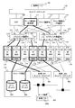
図1は、本発明の実施形態を示し、計算機システムの全体を示すブロック図である。図1の計算機システムは、複数のサーバ装置111で現用系のサーバ装置111と予備系(または待機系)のサーバ装置111を構成し、現用系と予備系でI/Oデバイス115を切り換え可能なI/Oスイッチ装置112を共用し、管理サーバ101からの指示に応じて現用系と予備系を切り替える。
FIG. 1 is a block diagram showing an embodiment of the present invention and showing the entire computer system. In the computer system of FIG. 1, a plurality of server apparatuses 111 constitute an active server apparatus 111 and a standby (or standby) server apparatus 111, and the I / O device 115 can be switched between the active system and the standby system. The I / O switch device 112 is shared, and the active system and the standby system are switched according to an instruction from the management server 101.
管理サーバ101は本実施形態の計算機システムにおける制御の中心である。管理サーバ101は、I/O構成管理部102と各種テーブル(108~109、123)、デバイス識別子取得プログラム121、およびデバイス識別子書き換えプログラム122を実行する。I/O構成管理部102は、デバイス識別子検出部103、サーバ障害回復部104、I/Oスイッチ切り替え部105、デバイス識別子取得選択部106、およびデバイス識別子書き換え部107を有する。
The management server 101 is the center of control in the computer system of this embodiment. The management server 101 executes an I / O configuration management unit 102 and various tables (108 to 109, 123), a device identifier acquisition program 121, and a device identifier rewrite program 122. The I / O configuration management unit 102 includes a device identifier detection unit 103, a server failure recovery unit 104, an I / O switch switching unit 105, a device identifier acquisition selection unit 106, and a device identifier rewrite unit 107.
管理サーバ101は、ネットワークスイッチ110を介して、複数のサーバ装置111、複数のI/Oスイッチ装置112、ファームウェア層の Service Processor(以後、SVPと表記する)120に接続される。I/Oスイッチ装置112は、サーバ装置111及びSVP120と接続する複数の上流ポート113と、複数のI/Oデバイス115と接続する複数の下流ポート114を備えて、サーバ装置111及びSVP120とI/Oデバイス115とを接続する。複数のI/Oデバイス115のうちのいくつかは、ストレージ装置116と接続されるHBA(Host Bus Adaptor)で構成され、サーバ装置111からストレージ装置116をアクセスすることができる。
The management server 101 is connected to a plurality of server devices 111, a plurality of I / O switch devices 112, and a firmware layer “Service” Processor (hereinafter referred to as SVP) 120 via a network switch 110. The I / O switch device 112 includes a plurality of upstream ports 113 connected to the server device 111 and the SVP 120, and a plurality of downstream ports 114 connected to the plurality of I / O devices 115. The O device 115 is connected. Some of the plurality of I / O devices 115 are configured by an HBA (Host Bus Adaptor) connected to the storage apparatus 116, and the storage apparatus 116 can be accessed from the server apparatus 111.
また、複数のI/Oデバイス115のうちのいくつかは、管理LANスイッチ401、業務LANスイッチ402に接続されるNIC(Network interface Card)で構成され、サーバ装置111から管理LANスイッチ401と業務LANスイッチ402にアクセスすることができる。
In addition, some of the plurality of I / O devices 115 are configured by a management interface switch 401 and a NIC (Network Interface Card) connected to the business LAN switch 402. The switch 402 can be accessed.
なお、複数のサーバ装置111は添え字#1~#3で個々のサーバ装置111を識別し、また、複数のI/Oスイッチ装置112は、添え字#1、#2で識別し、上流ポート113と下流ポート114はそれぞれ0~3の添え字で識別し、I/Oデバイス115は#1~#8で識別する。
The plurality of server devices 111 identify individual server devices 111 with subscripts # 1 to # 3, and the plurality of I / O switch devices 112 identify with subscripts # 1 and # 2, and upstream ports. 113 and the downstream port 114 are identified by subscripts 0 to 3, respectively, and the I / O device 115 is identified by # 1 to # 8.
管理LANスイッチ401は管理ソフトウェア4050(図4参照)が稼動するサーバ装置405等が、サーバ装置#1~#3を管理するための管理ネットワークを構成する。なお、サーバ装置405の管理ソフトウェア4050は、前記従来例で述べたように、サーバ装置#1~#3に接続されたNICのMACアドレスで、サーバ装置#1~#3を実行する。
The management LAN switch 401 constitutes a management network for the server device 405 or the like on which the management software 4050 (see FIG. 4) operates to manage the server devices # 1 to # 3. Note that the management software 4050 of the server device 405 executes the server devices # 1 to # 3 with the MAC addresses of the NICs connected to the server devices # 1 to # 3, as described in the conventional example.
業務LANスイッチ402はサーバ装置#1~#3と外部などの計算機を接続し、サーバ装置#1~#3のサービスを外部等の計算機に提供する業務ネットワークを構成する。
The business LAN switch 402 connects the server apparatuses # 1 to # 3 and external computers to form a business network that provides the services of the server apparatuses # 1 to # 3 to external computers.
管理サーバ101は、サーバ装置111やI/Oスイッチ装置112やI/Oデバイス115の障害を検知し回復する機能を有する。デバイス識別子検出部103は、サーバ装置111に接続されたI/Oデバイス115のデバイス識別子を検出する機能を有する。I/Oデバイス115のデバイス識別子としては、例えば、特定のネットワークに接続されているNICのMAC、特定のストレージ装置に接続されているHBAのWWN(World Wide Name)等である。
The management server 101 has a function of detecting and recovering from a failure of the server device 111, the I / O switch device 112, or the I / O device 115. The device identifier detection unit 103 has a function of detecting the device identifier of the I / O device 115 connected to the server device 111. The device identifier of the I / O device 115 is, for example, a MAC of a NIC connected to a specific network, a WWN (World Wide Name) of an HBA connected to a specific storage device, or the like.
サーバ障害回復部104は、サーバ装置111やI/Oスイッチ装置112やI/Oデバイス115の障害を検知し、検知された障害を回復する機能を有する。I/Oスイッチ切り替え部105は、サーバ管理テーブル108、およびサーバI/O構成情報テーブル109の情報を取得し、I/Oスイッチ装置112の切り替えを行う機能を有する。
The server failure recovery unit 104 has a function of detecting a failure in the server device 111, the I / O switch device 112, and the I / O device 115 and recovering the detected failure. The I / O switch switching unit 105 has a function of acquiring information in the server management table 108 and the server I / O configuration information table 109 and switching the I / O switch device 112.
デバイス識別子取得選択部106は、サーバ管理テーブル108、およびサーバI/O構成情報テーブル109の情報を取得し、取得した情報に基づいて特定のデバイス識別子を選択する機能を有する。デバイス識別子書き換え部107は、デバイス識別子取得選択部106によって選択されたデバイス識別子を任意のデバイス識別子に書き換える機能を有する。
The device identifier acquisition selection unit 106 has a function of acquiring information in the server management table 108 and the server I / O configuration information table 109 and selecting a specific device identifier based on the acquired information. The device identifier rewriting unit 107 has a function of rewriting the device identifier selected by the device identifier acquisition / selection unit 106 to an arbitrary device identifier.
サーバ管理テーブル108は、サーバ装置111の構成、およびサーバ装置111に接続されているI/Oスイッチ装置112の情報が格納される。サーバI/O構成情報テーブル109は、サーバ装置111に接続される一つまたは複数のI/Oスイッチ装置112と、I/Oデバイス115のI/O構成定義情報や状態などが格納される。デバイス識別子取得プログラム121は、I/Oデバイス115が有する固有の識別子を取得する機能を有するプログラムが格納される。デバイス識別子書き換えプログラム122は、I/Oデバイス115が有する固有の識別子を書き換える機能を有するプログラムが格納される。
The server management table 108 stores the configuration of the server device 111 and information on the I / O switch device 112 connected to the server device 111. The server I / O configuration information table 109 stores one or a plurality of I / O switch devices 112 connected to the server device 111 and I / O configuration definition information and status of the I / O device 115. The device identifier acquisition program 121 stores a program having a function of acquiring a unique identifier that the I / O device 115 has. The device identifier rewriting program 122 stores a program having a function of rewriting a unique identifier that the I / O device 115 has.
本実施形態では、管理サーバ101が、複数のサーバ装置111の何れかに障害が発生した場合に、障害が発生したサーバ装置111を一旦停止し、I/Oスイッチ装置112を切り替え、障害が発生したサーバ装置111に接続された複数のI/Oデバイス115の情報を書き換え、予備系のサーバ装置111を起動して障害が発生したサーバ装置111のI/Oデバイス115を引き継ぐ一実施形態を示す。
In this embodiment, when a failure occurs in any of the plurality of server devices 111, the management server 101 temporarily stops the server device 111 in which the failure has occurred, switches the I / O switch device 112, and a failure occurs. 1 shows an embodiment in which information of a plurality of I / O devices 115 connected to the server apparatus 111 is rewritten, the standby server apparatus 111 is started, and the I / O device 115 of the server apparatus 111 in which a failure has occurred is taken over. .
図2は、管理サーバ101の構成を示すブロック図である。管理サーバ101は、メモリ201とプロセッサ202とディスクインターフェース203とネットワークインターフェース204から構成される。メモリ201内には、サーバ管理テーブル108、サーバI/O構成情報テーブル109、デバイス識別子取得プログラム121、デバイス識別子書き換えプログラム122が格納される。
FIG. 2 is a block diagram showing the configuration of the management server 101. The management server 101 includes a memory 201, a processor 202, a disk interface 203, and a network interface 204. In the memory 201, a server management table 108, a server I / O configuration information table 109, a device identifier acquisition program 121, and a device identifier rewrite program 122 are stored.
I/O構成管理部102は、デバイス識別子検出部103、サーバ障害回復部104、I/Oスイッチ切り替え部105、デバイス識別子取得選択部106、およびデバイス識別子書き換え部107を含む。メモリ内のI/O構成管理部102、デバイス識別子取得プログラム121、およびデバイス識別子書き換えプログラム122は、プロセッサ202に読み込まれて実行される。ディスクインターフェース203は、管理サーバ101を起動するための上記各プログラムが格納された記憶媒体としてのディスク(図示省略)に接続される。ネットワークインターフェース204は、ネットワークスイッチ110等で構成されるネットワークに接続され各装置の障害情報などが転送され、また、管理サーバ101からの指令が転送される。なお、これらの機能はハードウェアで実装してもよい。
The I / O configuration management unit 102 includes a device identifier detection unit 103, a server failure recovery unit 104, an I / O switch switching unit 105, a device identifier acquisition selection unit 106, and a device identifier rewrite unit 107. The I / O configuration management unit 102, the device identifier acquisition program 121, and the device identifier rewrite program 122 in the memory are read and executed by the processor 202. The disk interface 203 is connected to a disk (not shown) as a storage medium in which the above-described programs for starting the management server 101 are stored. The network interface 204 is connected to a network constituted by the network switch 110 and the like, and failure information of each device is transferred, and a command from the management server 101 is transferred. Note that these functions may be implemented by hardware.
図3は、サーバ装置111の構成を示すブロック図である。図1に示す複数のサーバ装置111(#1~#3)は同一の構成である。サーバ装置111は、メモリ301、プロセッサ302、I/Oスイッチインターフェース303、およびBMC(Base board Management Controller)304を有する。メモリ301には、サーバ装置111で処理されるプログラムが格納され、このプログラムはプロセッサ302で実行される。I/Oスイッチインターフェース303は、I/Oスイッチ装置112に接続される。BMC304は、サーバ装置111内のハードウェアに障害が発生した場合に、ネットワークスイッチ110を介してSVP120に障害を通知する機能を有する。BMC304は障害の発生箇所とは独立に動作できるため、メモリ301やプロセッサ302に障害が発生したとしても障害通知を転送することができる。
FIG. 3 is a block diagram showing the configuration of the server device 111. The plurality of server apparatuses 111 (# 1 to # 3) shown in FIG. 1 have the same configuration. The server device 111 includes a memory 301, a processor 302, an I / O switch interface 303, and a BMC (Base board management Management Controller) 304. The memory 301 stores a program processed by the server device 111, and this program is executed by the processor 302. The I / O switch interface 303 is connected to the I / O switch device 112. The BMC 304 has a function of notifying the SVP 120 of a failure via the network switch 110 when a failure occurs in the hardware in the server device 111. Since the BMC 304 can operate independently of the location where the failure has occurred, the failure notification can be transferred even if a failure occurs in the memory 301 or the processor 302.
なお、本実施形態のI/Oスイッチ装置112、I/Oスイッチインターフェース303及びI/Oデバイス115はPCI-Expressの規格に準拠したものである。
Note that the I / O switch device 112, the I / O switch interface 303, and the I / O device 115 of this embodiment conform to the PCI-Express standard.
また、SVP120は、プロセッサとメモリとネットワークインターフェースを備えた計算機でありサーバ装置111の稼動状態を管理する。SVP120は、各サーバ装置111のBMC304を監視し、BMC304から障害の通知を受信すると、管理サーバ101に障害の発生したサーバ装置111を通知する。SVP120は管理サーバ101からサーバ装置111の起動やリセット等の指令を受信すると、対象となるサーバ装置111のBMC304に対して起動やリセット等を指令する。
The SVP 120 is a computer having a processor, a memory, and a network interface, and manages the operating state of the server device 111. When the SVP 120 monitors the BMC 304 of each server device 111 and receives a failure notification from the BMC 304, the SVP 120 notifies the management server 101 of the failed server device 111. When the SVP 120 receives a command for starting or resetting the server device 111 from the management server 101, the SVP 120 commands the BMC 304 of the target server device 111 to start or reset.
図4は、本発明における動作概要の一つを示している。サーバ装置111は複数のI/Oスイッチ装置112を介して複数のI/Oデバイス115と接続される。また、I/Oデバイス115はデバイスによって接続先が変わる。
FIG. 4 shows one of the operation outlines in the present invention. The server device 111 is connected to a plurality of I / O devices 115 via a plurality of I / O switch devices 112. The connection destination of the I / O device 115 varies depending on the device.
図4の例では、サーバ装置111(#1)が現用系を構成し、サーバ装置111(#3)が予備系を構成する。なお、以下では、各装置を上述の図1に示した添え字で識別する。図中I/Oデバイス#1、#3、#5、#7がNICで構成され、I/Oデバイス#2、#4、#6、#8がHBAで構成された例を示す。
In the example of FIG. 4, the server device 111 (# 1) constitutes an active system, and the server device 111 (# 3) constitutes a standby system. In the following, each device is identified by the subscript shown in FIG. In the figure, an example is shown in which I / O devices # 1, # 3, # 5, and # 7 are configured by NIC, and I / O devices # 2, # 4, # 6, and # 8 are configured by HBA.
現用系のサーバ装置#1はI/Oスイッチインターフェース303を介してI/Oスイッチ装置#1の上流ポート1とI/Oスイッチ装置#2の上流ポート1に接続される。I/Oスイッチ装置#1では、上流ポート1と下流ポート0、1、4が接続される。そして、下流ポート0にはNICで構成されたI/Oデバイス#1が接続され、下流ポート2、4にはHBAで構成されたI/Oデバイス#2、#4が接続される。I/Oスイッチ装置#2では、上流ポート1と下流ポート0が接続される。そして、I/Oスイッチ装置#2の下流ポート0にはNICで構成されたI/Oデバイス#5が接続される。
The active server device # 1 is connected to the upstream port 1 of the I / O switch device # 1 and the upstream port 1 of the I / O switch device # 2 via the I / O switch interface 303. In the I / O switch device # 1, the upstream port 1 and the downstream ports 0, 1, and 4 are connected. The downstream port 0 is connected to the I / O device # 1 configured with NIC, and the downstream ports 2 and 4 are connected to the I / O devices # 2 and # 4 configured with HBA. In the I / O switch device # 2, the upstream port 1 and the downstream port 0 are connected. An I / O device # 5 composed of NIC is connected to the downstream port 0 of the I / O switch device # 2.
I/Oデバイス#1のNICは、管理LANネットワークスイッチ401に接続され、I/Oデバイス#5のNICは、業務LANスイッチ402に接続される。I/Oデバイス#2のHBAはストレージ装置116のブートディスク403に接続され、I/Oデバイス#4のHBAはストレージ装置116のユーザディスク404に接続される。なお、ストレージ装置116のブートディスク403とユーザディスク404は、ロジカルユニットとして提供される。
The NIC of the I / O device # 1 is connected to the management LAN network switch 401, and the NIC of the I / O device # 5 is connected to the business LAN switch 402. The HBA of I / O device # 2 is connected to the boot disk 403 of the storage apparatus 116, and the HBA of I / O device # 4 is connected to the user disk 404 of the storage apparatus 116. Note that the boot disk 403 and the user disk 404 of the storage apparatus 116 are provided as logical units.
上記のように設定された現用系のサーバ装置#1は、I/Oスイッチ装置#1、#2を介してブートディスク403と、ユーザディスク404にアクセスし、管理LANスイッチ401を介してサーバ装置405と接続し、業務LANスイッチ402を介してサービスを提供する計算機に接続される。
The active server device # 1 set as described above accesses the boot disk 403 and the user disk 404 via the I / O switch devices # 1 and # 2, and the server device via the management LAN switch 401. It is connected to a computer that provides a service via the business LAN switch 402.
上記の構成において、現用系のサーバ装置#1はI/Oスイッチ装置#1、#2を介して接続されたI/Oデバイス#1,#2、#4、#5のうち、管理LANスイッチ401に接続された指定デバイス識別子のみを取得し、管理サーバ101に対して送信する。この指定デバイス識別子はユーザ(または管理者)によって任意に設定可能である。例えば、サーバ装置#1のI/Oデバイス#1、#5がNICの場合、サーバ装置#1は、I/Oスイッチインターフェース303に接続された複数のI/Oデバイス#1、#5のうち、管理LANスイッチ401に接続されたNIC(I/Oデバイス#1)の固有識別子(MAC)のみを指定デバイス識別子として管理サーバ101に送信する。
In the above configuration, the active server device # 1 is the management LAN switch among the I / O devices # 1, # 2, # 4, and # 5 connected via the I / O switch devices # 1 and # 2. Only the designated device identifier connected to 401 is acquired and transmitted to the management server 101. This designated device identifier can be arbitrarily set by the user (or administrator). For example, when the I / O devices # 1 and # 5 of the server apparatus # 1 are NICs, the server apparatus # 1 is a plurality of I / O devices # 1 and # 5 connected to the I / O switch interface 303. Then, only the unique identifier (MAC) of the NIC (I / O device # 1) connected to the management LAN switch 401 is transmitted to the management server 101 as the designated device identifier.
すなわち、業務LANスイッチ401は、他の計算機と接続してサーバ装置#1~#3のサービスを提供するため、障害発生時に現用系のサーバ装置#1から予備系のサーバ装置3にフェイルオーバを行った後も、現用系のサーバ装置#1から予備系のサーバ装置3が引き継いだNIC(I/Oデバイス#5)の識別子(MACアドレス)を変更してはならないネットワークを構成する。
In other words, the business LAN switch 401 is connected to other computers to provide the services of the server devices # 1 to # 3, and therefore, when a failure occurs, the active LAN device 401 performs a failover from the active server device # 1 to the standby server device 3. After that, a network in which the identifier (MAC address) of the NIC (I / O device # 5) taken over by the standby server device 3 from the active server device # 1 should not be changed is configured.
これに対して、管理LANスイッチ402は、サーバ装置405と接続して管理ソフトウェア4050によりサーバ装置#1~#3の管理を行うため、障害発生時に現用系のサーバ装置#1から予備系のサーバ装置3にフェイルオーバを行った後は、現用系のサーバ装置#1から予備系のサーバ装置3が引き継いだNIC(I/Oデバイス#3)の識別子(MACアドレス)を変更するネットワークを構成する。
On the other hand, since the management LAN switch 402 is connected to the server device 405 and manages the server devices # 1 to # 3 by the management software 4050, when the failure occurs, the management server switch # 1 switches to the standby server. After failing over to the device 3, a network is configured in which the identifier (MAC address) of the NIC (I / O device # 3) taken over by the standby server device 3 from the active server device # 1 is changed.
図4の状態では、予備系のサーバ装置#3は、I/Oスイッチ装置#1の上流ポート3と、I/Oスイッチ装置#2の上流ポート3にそれぞれ接続されるが、各上流ポート3には下流ポートが接続されていない。
In the state of FIG. 4, the standby server device # 3 is connected to the upstream port 3 of the I / O switch device # 1 and the upstream port 3 of the I / O switch device # 2, respectively. Is not connected to the downstream port.
図5は、本発明における動作概要の一つを示し、フェイルオーバの例を示している。図5は、図4に示した環境で現用系のサーバ装置#1に障害が発生して、予備系のサーバ装置#3に処理を引き継ぐ例を示している。
FIG. 5 shows one of the operation outlines in the present invention and shows an example of failover. FIG. 5 shows an example in which a failure occurs in the active server device # 1 in the environment shown in FIG. 4 and processing is taken over by the standby server device # 3.
現用系のサーバ装置#1で障害が発生した場合に、管理サーバ101は現用系のサーバ装置#1を一旦停止する。そして、管理サーバ101はI/Oスイッチ装置112へ現用系のサーバ装置#1から予備系のサーバ装置#3への切り換えを指示し、I/Oスイッチ装置112は上流ポート113と下流ポート114の接続を切り替えることにより、現用系のサーバ装置#1に接続されている全てのI/Oデバイス115を、予備系のサーバ装置#3へ接続する。
When a failure occurs in the active server device # 1, the management server 101 temporarily stops the active server device # 1. Then, the management server 101 instructs the I / O switch device 112 to switch from the active server device # 1 to the standby server device # 3, and the I / O switch device 112 connects the upstream port 113 and the downstream port 114. By switching the connection, all the I / O devices 115 connected to the active server device # 1 are connected to the standby server device # 3.
つまり、サーバ装置111とI/Oスイッチ装置112間の経路は、図5に示す経路501から経路503へ、経路502から経路504へと変更される。このとき、I/Oスイッチ装置112とI/Oデバイス115間の経路は変更されないことが重要である。
That is, the path between the server apparatus 111 and the I / O switch apparatus 112 is changed from the path 501 to the path 503 and the path 502 to the path 504 shown in FIG. At this time, it is important that the path between the I / O switch device 112 and the I / O device 115 is not changed.
次に管理サーバ101は、予備系のサーバ装置#3を起動し、管理LANスイッチ401に接続されたNIC(I/Oデバイス#1)の特定のデバイス識別子(MAC)のみを予め設定した仮想の識別子に書き換える。
Next, the management server 101 activates the standby server device # 3 and sets a virtual device in which only a specific device identifier (MAC) of the NIC (I / O device # 1) connected to the management LAN switch 401 is set in advance. Rewrite the identifier.
このとき、管理サーバ101は、管理LANスイッチ401に接続されているI/Oデバイス#1(NIC)のデバイス識別子(MAC)のみの書き換えを指示し、業務LANスイッチ402に接続されているI/Oデバイス#5(NIC)のデバイス識別子については書き換えは行わないところに特徴がある。また、このデバイス識別子の書き換えはI/Oデバイス115がHBAの場合には、デバイス識別子(WWN)などに対しても適用可能である。
At this time, the management server 101 instructs to rewrite only the device identifier (MAC) of the I / O device # 1 (NIC) connected to the management LAN switch 401, and the I / O connected to the business LAN switch 402. The device identifier of O device # 5 (NIC) is characterized in that it is not rewritten. This device identifier rewrite can also be applied to a device identifier (WWN) or the like when the I / O device 115 is an HBA.
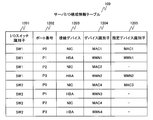
図6は、サーバ管理テーブル108を示す。カラム1101は、サーバ装置識別子を示す。カラム1102は、サーバ装置111のプロセッサ構成、カラム1103はメモリ容量が格納される。カラム1104は、当該サーバ装置111が接続されているI/Oスイッチ装置112の識別子が格納される。
FIG. 6 shows the server management table 108. A column 1101 indicates a server device identifier. Column 1102 stores the processor configuration of the server apparatus 111, and column 1103 stores memory capacity. A column 1104 stores an identifier of the I / O switch device 112 to which the server device 111 is connected.
カラム1105は当該サーバ装置111が接続されているI/Oスイッチ装置112の上流ポート113のポート番号が格納される。カラム1106は当該サーバ装置111に割り当てられているI/Oデバイス115が接続された下流ポート114のポート番号が格納される。
Column 1105 stores the port number of the upstream port 113 of the I / O switch device 112 to which the server device 111 is connected. A column 1106 stores the port number of the downstream port 114 to which the I / O device 115 assigned to the server device 111 is connected.
サーバ管理テーブル108によって、サーバ装置#1~#3(図中HOST1~3)に割り当てられたI/Oデバイス115のI/Oスイッチ装置112の識別子と、下流ポート114のポート番号と、上流ポート113のポート番号の対応関係が保持される。
According to the server management table 108, the identifier of the I / O switch device 112 of the I / O device 115 assigned to the server devices # 1 to # 3 (HOST1 to 3 in the figure), the port number of the downstream port 114, and the upstream port Correspondence relationship of port number 113 is maintained.
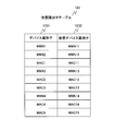
図7は、サーバI/O構成情報テーブル109を示す。カラム1202はI/Oスイッチ装置112の識別子が格納される。カラム1202は、I/Oスイッチ装置112の下流ポート114のポート番号が格納される。カラム1203は下流ポート114に接続されたI/Oデバイス115の種類が格納される。カラム1204は、I/Oデバイス115の固有の識別子がデバイス識別子として格納される。カラム1205は、サーバ装置111から通知された指定デバイス識別子が格納される。また、指定デバイス識別子は、接続デバイス1203に対して複数の指定デバイス識別子が格納される場合もある。
FIG. 7 shows the server I / O configuration information table 109. A column 1202 stores an identifier of the I / O switch device 112. A column 1202 stores the port number of the downstream port 114 of the I / O switch device 112. A column 1203 stores the type of the I / O device 115 connected to the downstream port 114. A column 1204 stores a unique identifier of the I / O device 115 as a device identifier. A column 1205 stores designated device identifiers notified from the server device 111. In addition, the designated device identifier may store a plurality of designated device identifiers for the connection device 1203.
デバイス識別子は、管理対象のI/Oデバイス115に固有の識別子で、例えば、MACやWWNで構成される。指定デバイス識別子は、管理対象のサーバ装置111に接続されているI/Oデバイス115のうち、管理ネットワークに接続されているI/Oデバイス115のデバイス識別子を示す。なお、指定デバイス識別子はデバイス識別子に代わって、管理ネットワークに接続されていることを示すフラグを用いてもよい。
The device identifier is an identifier unique to the I / O device 115 to be managed, and is composed of, for example, MAC or WWN. The designated device identifier indicates the device identifier of the I / O device 115 connected to the management network among the I / O devices 115 connected to the server device 111 to be managed. Note that a flag indicating that the designated device identifier is connected to the management network may be used instead of the device identifier.
サーバI/O構成情報テーブル109を管理することによって、一つのサーバ装置111に対して複数のI/O構成を管理することができる。
By managing the server I / O configuration information table 109, a plurality of I / O configurations can be managed for one server device 111.
図8は、仮想識別子テーブル123を示す説明図である。仮想識別子テーブル123は、I/Oスイッチ装置112に接続されているI/Oデバイス115の固有の識別子を格納するデバイス識別子として格納するカラム1231と、管理サーバ101が設定した仮想デバイス識別子を格納するカラム1232から構成される。
FIG. 8 is an explanatory diagram showing the virtual identifier table 123. The virtual identifier table 123 stores a column 1231 for storing a unique identifier of the I / O device 115 connected to the I / O switch device 112 as a device identifier, and a virtual device identifier set by the management server 101. The column 1232 is configured.
仮想デバイス識別子は、サーバ装置111がフェイルオーバなどで切り替わったことをサーバ装置405に通知するため、I/Oデバイス115に固有のデバイス識別子に代わってI/Oデバイス115に付与する識別子である。
The virtual device identifier is an identifier assigned to the I / O device 115 in place of the device identifier unique to the I / O device 115 in order to notify the server device 405 that the server device 111 has been switched due to failover or the like.
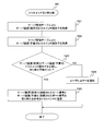
図9は、管理サーバ101のデバイス識別子検出部103で行われる処理の一例を示すフローチャートである。本処理は、管理サーバ101がサーバ装置111を管理する場合に必ず行われる処理で、例えば、サーバ装置111の起動、停止やI/Oデバイス115の変更などである。
FIG. 9 is a flowchart illustrating an example of processing performed by the device identifier detection unit 103 of the management server 101. This processing is always performed when the management server 101 manages the server device 111. For example, the server device 111 is started and stopped, and the I / O device 115 is changed.
ステップ1301では、管理サーバ101のデバイス識別子検出部103がサーバ管理テーブル108、およびサーバI/O構成情報テーブル109から、サーバ装置111の指定デバイス識別子を取得する。ステップ1302では、デバイス識別子検出部103は、サーバ装置111の指定デバイス識別子情報の取得の有無を判定する。指定デバイス識別子が取得された場合にはステップ1303へ進み、指定デバイス識別子がなければ処理を終了する。
In step 1301, the device identifier detection unit 103 of the management server 101 acquires the designated device identifier of the server device 111 from the server management table 108 and the server I / O configuration information table 109. In step 1302, the device identifier detection unit 103 determines whether or not the designated device identifier information of the server device 111 is acquired. If the designated device identifier is acquired, the process proceeds to step 1303. If there is no designated device identifier, the process is terminated.
ステップ1303では、デバイス識別子検出部103がサーバ装置111に指定デバイス識別子の送信命令を発行する。例えば、サーバ装置111にI/Oデバイス(NIC)115が接続されている場合には、MACアドレスの送信命令を送信する。この送信命令は、複数のサーバ装置111に接続されている複数のI/Oデバイス115に対し、複数の指定デバイス識別子の送信命令を行うことが可能である。
In step 1303, the device identifier detection unit 103 issues a designated device identifier transmission command to the server device 111. For example, when an I / O device (NIC) 115 is connected to the server apparatus 111, a MAC address transmission command is transmitted. This transmission command can send a plurality of designated device identifier transmission commands to a plurality of I / O devices 115 connected to a plurality of server apparatuses 111.
ステップ1304では、デバイス識別子検出部103が指定デバイス識別子の送信命令に対する応答として受信した指定デバイス識別子をサーバI/O構成情報テーブル109に格納する。
In step 1304, the device identifier detection unit 103 stores the designated device identifier received as a response to the designated device identifier transmission command in the server I / O configuration information table 109.
上記処理により、デバイス識別子検出部103は、各サーバ装置111から管理ネットワークに接続されているI/Oデバイス115のデバイス識別子を指定デバイス識別子として取得し、サーバI/O構成情報テーブル109の指定デバイス識別子1205に格納する。なお、サーバ装置111は、デバイス識別子検出部103からの指定デバイス識別子の送信命令に対して、管理ネットワークに接続されていないI/Oデバイス115については、デバイス識別子を通知しない。例えば、図4の構成では、サーバ装置111は、管理LANスイッチ401に接続されているI/Oデバイス#1のMACを管理サーバ101に応答するが、I/Oデバイス#2、#4、#5のデバイス識別子については管理サーバ101に通知しない。また、サーバ装置111は、管理ネットワークの所定の装置(例えば、サーバ装置405)と通信可能なI/Oデバイス115を、管理ネットワークに接続されているI/Oデバイス115として判定することができる。
Through the above processing, the device identifier detection unit 103 acquires the device identifier of the I / O device 115 connected to the management network from each server device 111 as the designated device identifier, and designates the designated device in the server I / O configuration information table 109. The identifier 1205 is stored. Note that the server apparatus 111 does not notify the device identifier of the I / O device 115 that is not connected to the management network in response to the designated device identifier transmission command from the device identifier detection unit 103. For example, in the configuration of FIG. 4, the server apparatus 111 responds to the management server 101 with the MAC of the I / O device # 1 connected to the management LAN switch 401, but the I / O devices # 2, # 4, # The device identifier of 5 is not notified to the management server 101. Further, the server apparatus 111 can determine an I / O device 115 that can communicate with a predetermined apparatus (for example, the server apparatus 405) in the management network as an I / O device 115 connected to the management network.
上記処理は、管理サーバ101が管理対象とするサーバ装置111の全てについて繰り返して行うことができる。
The above process can be repeated for all of the server apparatuses 111 that are managed by the management server 101.
なお、管理サーバ101が管理ネットワークに接続されている場合は、管理サーバ101が管理ネットワークからI/Oデバイス115のデバイス識別子を取得するようにしてもよい。
When the management server 101 is connected to the management network, the management server 101 may acquire the device identifier of the I / O device 115 from the management network.
図10は、サーバ障害回復部104で行われる処理の一例を示すフローチャートである。サーバ障害回復部104は、SVP120からサーバ装置111の障害の通知を受信すると図10の処理を実行する。なお、障害の検知は、SVP120からの通知に限らず、サーバ障害回復部104が各サーバ装置111のハートビートを検知するものであってもよく、公知または周知の手法を適用することができる。
FIG. 10 is a flowchart illustrating an example of processing performed by the server failure recovery unit 104. When the server failure recovery unit 104 receives a notification of the failure of the server device 111 from the SVP 120, the server failure recovery unit 104 executes the process of FIG. The failure detection is not limited to the notification from the SVP 120, and the server failure recovery unit 104 may detect the heartbeat of each server device 111, and a known or well-known method can be applied.
ステップ1041では、サーバ障害回復部104が、現用系のサーバ装置111(図4のサーバ装置#1)の障害を検知した場合にSVP120から通知された現用系のサーバ装置111の起動を停止する。ステップ1402では、サーバ障害回復部104がSVP120、およびI/Oスイッチ装置112からI/Oスイッチ情報を取得し、サーバ管理テーブル108、およびサーバI/O構成情報テーブル109を更新する。I/Oスイッチ情報は、全てのI/Oスイッチ装置112の上流ポート113と下流ポート114の接続関係を示す。ステップ1402では、サーバ障害回復部104が、障害発生により停止した現用系のサーバ装置111に接続されていた下流ポート114を特定し、停止した現用系のサーバ装置111が使用していたI/Oデバイス115を取得する。
In step 1041, when the server failure recovery unit 104 detects a failure in the active server device 111 (server device # 1 in FIG. 4), the server failure recovery unit 104 stops the activation of the active server device 111 notified from the SVP 120. In step 1402, the server failure recovery unit 104 acquires I / O switch information from the SVP 120 and the I / O switch device 112 and updates the server management table 108 and the server I / O configuration information table 109. The I / O switch information indicates the connection relationship between the upstream port 113 and the downstream port 114 of all the I / O switch devices 112. In step 1402, the server failure recovery unit 104 identifies the downstream port 114 connected to the active server device 111 that has stopped due to the occurrence of a failure, and the I / O used by the stopped active server device 111. The device 115 is acquired.
ステップ1403では、停止した現用系のサーバ装置111を予備系のサーバ装置111(図4のサーバ装置#3)に切り替えるため、I/Oスイッチ装置112の切り替えをI/Oスイッチ切り替え部105が実行する。すなわち、I/Oスイッチ切り替え部105は、サーバ障害回復部104が取得した各I/Oスイッチ装置112の上流ポート113と下流ポート114の接続関係から、障害により停止した現用系のサーバ装置111のI/Oデバイス115を、予備系のサーバ装置111に切り替えるよう指令する。この指令は、対象となるI/Oデバイス115の下流ポート114を、予備系のサーバ装置111が接続された上流ポート113に切り替える指令であり、I/Oスイッチ切り替え部105が各I/Oスイッチ装置112に指令する。なお、I/Oスイッチ切り替え部105で実行される処理の詳細については図11で後述する。
In step 1403, the I / O switch switching unit 105 executes switching of the I / O switch device 112 in order to switch the stopped active server device 111 to the standby server device 111 (server device # 3 in FIG. 4). To do. That is, the I / O switch switching unit 105 determines whether the active server device 111 stopped due to a failure from the connection relationship between the upstream port 113 and the downstream port 114 of each I / O switch device 112 acquired by the server failure recovery unit 104. A command is issued to switch the I / O device 115 to the standby server apparatus 111. This command is a command for switching the downstream port 114 of the target I / O device 115 to the upstream port 113 to which the standby server device 111 is connected, and the I / O switch switching unit 105 performs switching to each I / O switch. Command device 112. Details of processing executed by the I / O switch switching unit 105 will be described later with reference to FIG.
ステップ1404では、I/Oスイッチ切り替え部105がステップ1403で指令したI/Oスイッチ装置112の切り替えの成功、失敗を判定する。この判定は、I/Oスイッチ切り替え部105の指令に対するI/Oスイッチ装置112の応答などに基づいて上流ポート113と下流ポート114の接続の切り替えが成功したか否かを判定することができる。
In step 1404, the I / O switch switching unit 105 determines success or failure of switching of the I / O switch device 112 instructed in step 1403. This determination can determine whether or not the switching of the connection between the upstream port 113 and the downstream port 114 is successful based on the response of the I / O switch device 112 to the command of the I / O switch switching unit 105.
ステップ1405では、I/Oスイッチ切り替え部105により障害の発生した現用系のサーバ装置111のI/Oデバイス115が予備系のサーバ装置111に接続された後、サーバ障害回復部104が、予備系のサーバ装置111を起動する。このとき、予備系のサーバ装置111に接続されるI/Oデバイス115が管理ネットワークに接続されるNIC(図4のI/Oデバイス#1)の場合、対象のNICにVLAN(Virtual LAN)を予め設定することで、NICを管理ネットワークから隔離してもよい。これは、管理ネットワークに接続されたサーバ装置405の管理ソフトウェア4050がNICのMACアドレスでサーバ装置111の管理を行うため、I/Oデバイス115が管理ネットワークに接続されたNICで予備系のサーバ装置111をそのまま起動すると、管理ソフトウェア4050は、障害が発生したサーバ装置111が再起動したと誤認するのを防ぐため、このNICをVLANにより管理ネットワークから隔離しておく。
In step 1405, after the I / O device 115 of the active server device 111 in which the failure has occurred is connected to the standby server device 111 by the I / O switch switching unit 105, the server failure recovery unit 104 The server apparatus 111 is started. At this time, if the I / O device 115 connected to the standby server device 111 is a NIC (I / O device # 1 in FIG. 4) connected to the management network, a VLAN (Virtual LAN) is assigned to the target NIC. The NIC may be isolated from the management network by setting in advance. This is because the management software 4050 of the server device 405 connected to the management network manages the server device 111 with the MAC address of the NIC, so that the I / O device 115 is a standby server device with the NIC connected to the management network. When 111 is started as it is, the management software 4050 isolates this NIC from the management network by VLAN in order to prevent the server apparatus 111 in which the failure has occurred from being mistakenly restarted.
ステップ1046では、予備系のサーバ装置111に接続されるI/Oデバイス115の指定デバイス識別子の取得、および選択をデバイス識別子取得選択部106が実行する。デバイス識別子取得選択部106は、図12で後述するように、管理ネットワークに接続されたI/Oデバイス115のうち、仮想デバイス識別子を付与するI/Oデバイス115を選択する。図4の例では、管理ネットワークに接続されたI/Oデバイス#1が仮想デバイス識別子の付与対象として選択される。
In step 1046, the device identifier acquisition / selection unit 106 executes acquisition and selection of the designated device identifier of the I / O device 115 connected to the standby server apparatus 111. As will be described later with reference to FIG. 12, the device identifier acquisition / selection unit 106 selects an I / O device 115 to which a virtual device identifier is assigned from among the I / O devices 115 connected to the management network. In the example of FIG. 4, the I / O device # 1 connected to the management network is selected as a virtual device identifier assignment target.
ステップ1047では、予備系のサーバ装置111に接続されるI/Oデバイス115の指定デバイス識別子の書き換えをデバイス識別子書き換え部107が実行する。
In step 1047, the device identifier rewriting unit 107 rewrites the designated device identifier of the I / O device 115 connected to the standby server apparatus 111.
デバイス識別子書き換え部107は、図13で後述するように、上記ステップ1406で選択されたI/Oデバイス115(I/Oデバイス#1のNIC)のデバイス識別子(図8のMAC1)を、仮想識別子テーブル123の仮想デバイス識別子(図8のMAC11)で書き換えるように予備系のサーバ装置111に指令する。
As will be described later with reference to FIG. 13, the device identifier rewriting unit 107 uses the device identifier (MAC 1 in FIG. 8) of the I / O device 115 (NIC of I / O device # 1) selected in step 1406 as a virtual identifier. The backup server apparatus 111 is instructed to rewrite with the virtual device identifier (MAC 11 in FIG. 8) in the table 123.
上記処理により、障害が発生した現用系のサーバ装置111のI/Oデバイス115を引き継いだ予備系のサーバ装置111は、I/Oデバイス115のうち管理ネットワークに接続されるNIC(I/Oデバイス#1)について、管理サーバ101から仮想デバイス識別子(MAC11)を受信し、NICのデバイス識別子(MAC1)を仮想デバイス識別子(MAC11)に書き換える。
As a result of the above processing, the standby server device 111 taking over the I / O device 115 of the active server device 111 in which a failure has occurred is connected to the management network among the I / O devices 115 (I / O devices). For # 1), the virtual device identifier (MAC11) is received from the management server 101, and the NIC device identifier (MAC1) is rewritten to the virtual device identifier (MAC11).
これにより、管理ネットワークに接続されたサーバ装置405の管理ソフトウェア4050は、新たな仮想デバイス識別子をデバイス識別子として認識し、停止したサーバ装置111を予備系のサーバ装置111が引き継いだことを認識することが可能となる。
As a result, the management software 4050 of the server device 405 connected to the management network recognizes the new virtual device identifier as the device identifier, and recognizes that the standby server device 111 has taken over the stopped server device 111. Is possible.
したがって、現用系サーバ装置111と予備系サーバ装置111をPCI-ExpressのI/Oスイッチ装置112にそれぞれ接続してI/Oデバイス115を共用する状態で、現用系サーバ装置111から予備系サーバ装置111への切り替えが行われた場合でも、管理ネットワークのサーバ装置405の管理ソフトウェア4050は各サーバ装置111の物理位置を把握することができる。
Therefore, the active server device 111 and the standby server device 111 are respectively connected to the PCI-Express I / O switch device 112 and the I / O device 115 is shared, and the active server device 111 and the standby server device are shared. Even when switching to 111 is performed, the management software 4050 of the server device 405 of the management network can grasp the physical position of each server device 111.
一方、I/Oデバイス115のうち業務ネットワークに接続されるNICのデバイス識別子は、障害発生前と同一であるので、他の計算機などは障害発生前と同様に予備系のサーバ装置111にアクセスすることができる。
On the other hand, the device identifier of the NIC connected to the business network among the I / O devices 115 is the same as that before the failure occurs, so other computers access the backup server device 111 as before the failure occurrence. be able to.
なお、管理ネットワークに接続されているI/Oデバイス115をVLANにより隔離した場合には、デバイス識別子を仮想デバイス識別子に書き換えた後に、VLANの設定を変更して管理ネットワークに接続させればよい。
In addition, when the I / O device 115 connected to the management network is isolated by the VLAN, after rewriting the device identifier to the virtual device identifier, the VLAN setting may be changed and connected to the management network.
図11は、I/Oスイッチ切り替え部105で行われる処理の一例を示すフローチャートである。この処理は、上記図10のステップ1403で行われる処理の詳細である。
FIG. 11 is a flowchart illustrating an example of processing performed by the I / O switch switching unit 105. This process is a detail of the process performed in step 1403 of FIG.
ステップ1501では、I/Oスイッチ切り替え部105が、サーバ管理テーブル108、およびサーバI/O構成情報テーブル109から、障害が発生したサーバ装置111に接続されるI/Oスイッチ装置112のI/O識別子を取得する。
In step 1501, the I / O switch switching unit 105 determines from the server management table 108 and the server I / O configuration information table 109 that the I / O switch device 112 connected to the server device 111 in which the failure has occurred. Get an identifier.
ステップ1502では、I/Oスイッチ切り替え部105が、サーバ管理テーブル108、およびサーバI/O構成情報テーブル109から、予備系のサーバ装置111に接続されているI/Oスイッチ装置112のI/O識別子を取得する。ステップ1503では、現用系のサーバ装置111に接続されるI/Oスイッチ装置112のI/Oスイッチ識別子の全てが、予備系のサーバ装置111に接続されるI/Oスイッチ装置112のI/Oスイッチ識別子に含まれるか比較し、I/Oスイッチ装置112の切り替え可能か判定する。この比較は、スイッチ切り替えの判定条件となるため、非常に重要である。I/Oスイッチ装置112の切り替えが不能な場合のステップ1504では、ユーザ(または管理サーバ101の管理者)にエラーを通知する。
In step 1502, the I / O switch switching unit 105 performs I / O of the I / O switch device 112 connected to the standby server device 111 from the server management table 108 and the server I / O configuration information table 109. Get an identifier. In step 1503, all of the I / O switch identifiers of the I / O switch device 112 connected to the active server device 111 are changed to the I / O of the I / O switch device 112 connected to the standby server device 111. It is determined whether the I / O switch device 112 can be switched by comparing whether it is included in the switch identifier. This comparison is very important because it becomes a judgment condition for switching. In step 1504 when the I / O switch device 112 cannot be switched, an error is notified to the user (or the administrator of the management server 101).
一方、I/Oスイッチ装置112の切り替えが可能な場合のステップ1505では、現用系のサーバ装置111に接続されるI/Oスイッチ装置112のポート番号を、予備系のサーバ装置111に接続されるI/Oスイッチ装置112のポート番号に書き換える命令を全てのI/Oスイッチ装置112に送信する。
On the other hand, in step 1505 when switching of the I / O switch device 112 is possible, the port number of the I / O switch device 112 connected to the active server device 111 is connected to the standby server device 111. A command for rewriting the port number of the I / O switch device 112 is transmitted to all the I / O switch devices 112.
図12は、デバイス識別子取得選択部106で行われる処理の一例を示すフローチャートである。この処理は、上記図10のステップ1406で行われる処理の詳細である。
FIG. 12 is a flowchart illustrating an example of processing performed by the device identifier acquisition / selection unit 106. This process is a detail of the process performed in step 1406 of FIG.
ステップ1601では、デバイス識別子取得選択部106はデバイス識別子取得プログラム121により全てのサーバ装置111に接続されているI/Oデバイス115のデバイス識別子を全て取得する。
In step 1601, the device identifier acquisition selection unit 106 acquires all the device identifiers of the I / O devices 115 connected to all the server apparatuses 111 using the device identifier acquisition program 121.
ステップ1602では、デバイス識別子取得選択部106は上記ステップ1601で取得したデバイス識別子をサーバI/O構成情報テーブル109に格納する。ステップ1603では、サーバ管理テーブル108、およびサーバI/O構成情報テーブル109から、障害が発生した現用系のサーバ装置111に接続されるI/Oスイッチ装置112の指定デバイス識別子を取得する。
In step 1602, the device identifier acquisition / selection unit 106 stores the device identifier acquired in step 1601 in the server I / O configuration information table 109. In step 1603, the designated device identifier of the I / O switch device 112 connected to the active server device 111 where the failure has occurred is acquired from the server management table 108 and the server I / O configuration information table 109.
ステップ1604では、デバイス識別子取得選択部106はステップ1602で取得した指定デバイス識別子を検索キーとして、仮想識別子テーブル123を検索し、一致するデバイス識別子が存在するか判定する。この検索は、書き換え対象のデバイス識別子の有無を判定するため、非常に重要な意味を持つ。ステップ1605では、ステップ1604で一致したデバイス識別子に対応する仮想デバイス識別子1232を書き換え対象として選択する。
In step 1604, the device identifier acquisition / selection unit 106 searches the virtual identifier table 123 using the specified device identifier acquired in step 1602 as a search key, and determines whether a matching device identifier exists. This search has a very important meaning because it determines the presence or absence of a device identifier to be rewritten. In step 1605, the virtual device identifier 1232 corresponding to the device identifier matched in step 1604 is selected as a rewrite target.
図13は、デバイス識別子書き換え部107で行われる処理の一例を示すフローチャートである。この処理は、上記図10のステップ1407で行われる処理の詳細である。
FIG. 13 is a flowchart illustrating an example of processing performed by the device identifier rewriting unit 107. This process is a detail of the process performed in step 1407 of FIG.
ステップ1701では、デバイス識別子書き換え部107が、デバイス識別子取得選択部106で書き換え対象のデバイス識別子が選択されているか否かを判定する。デバイス識別子取得選択部106で書き換え対象のデバイス識別子が選択されている場合は、ステップ1702で、デバイス識別子取得選択部106が書き換え対象のデバイス識別子を仮想デバイス識別子に書き換える。このとき、デバイス識別子取得選択部106で書き換え対象のデバイス識別子のみを書き換え、他のデバイス識別子は全て書き換えないところが重要である。つまり、管理ネットワークに接続されているI/Oデバイス115のデバイス識別子のみを仮想デバイス識別子に書き換えることで、起動した予備系のサーバ装置111をサーバ装置405の管理ソフトウェア4050に認識させる。一方、その他のI/Oデバイス115については、現用系のサーバ装置111で用いていたデバイス識別子をそのまま使用することで、予備系のサーバ装置111は切り替え以前と同一の環境でサービスの提供やストレージ装置116へのアクセスを行うことができる。
In step 1701, the device identifier rewriting unit 107 determines whether or not the device identifier to be rewritten has been selected by the device identifier acquisition / selection unit 106. If the device identifier to be rewritten is selected by the device identifier acquisition / selection unit 106, in step 1702, the device identifier acquisition / selection unit 106 rewrites the device identifier to be rewritten to a virtual device identifier. At this time, it is important that the device identifier acquisition / selection unit 106 rewrites only the device identifier to be rewritten and does not rewrite all other device identifiers. In other words, only the device identifier of the I / O device 115 connected to the management network is rewritten to the virtual device identifier, thereby causing the management software 4050 of the server device 405 to recognize the activated standby server device 111. On the other hand, for the other I / O devices 115, the device identifier used in the active server device 111 is used as it is, so that the standby server device 111 provides service and storage in the same environment as before the switching. Access to device 116 can be made.
なお、上記では、障害が発生したときに予備系のサーバ装置111へ切り替える例を示したが、現用系のサーバ装置111の保守などで管理サーバ101が予備系のサーバ装置111への切り換えを指示した場合にも、上述したように管理ソフトウェア4050からアクセスされるI/Oデバイス115のデバイス識別子を、管理サーバ101で予め設定された仮想デバイス識別子に書き換えるようにしてもよい。この場合、サーバ障害回復部104は、サーバ切り替え部として機能し、管理サーバ101の図示しないコンソールなどからの指令によって、現用系のサーバ装置111から予備系のサーバ装置111への切り替えを実行する。
In the above, an example of switching to the standby server device 111 when a failure occurs is shown. However, the management server 101 instructs switching to the standby server device 111 for maintenance of the active server device 111 or the like. In this case, as described above, the device identifier of the I / O device 115 accessed from the management software 4050 may be rewritten to a virtual device identifier set in advance by the management server 101. In this case, the server failure recovery unit 104 functions as a server switching unit, and executes switching from the active server device 111 to the standby server device 111 according to a command from a console (not shown) of the management server 101.
また、I/Oデバイス115のデバイス識別子を仮想デバイス識別子に書き換える処理については、上述したように管理サーバ101が予備系のサーバ装置111へ指令する他、管理サーバ101がSVP120にデバイス識別子と仮想デバイス識別子を指示し、SVP120がBMC304を経由して対象のI/Oデバイス115のデバイス識別子を仮想デバイス識別子に書き換えるようにしてもよい。
As for the process of rewriting the device identifier of the I / O device 115 to the virtual device identifier, the management server 101 instructs the standby server device 111 as described above, and the management server 101 sends the device identifier and virtual device to the SVP 120. The identifier may be instructed, and the SVP 120 may rewrite the device identifier of the target I / O device 115 with the virtual device identifier via the BMC 304.
また、上記では管理サーバ101と、MACアドレスでサーバ装置111の物理位置を管理する管理ソフトウェア4050を実行するサーバ装置405を異なる計算機で構成した例を示したが、管理サーバ101で管理ソフトウェア4050を実行してもよい。この場合、管理サーバ101に複数のネットワークインターフェースを設けて、ネットワークスイッチ110と管理LANスイッチ401にそれぞれ接続すればよい。
Moreover, although the example which comprised the management server 101 and the server apparatus 405 which executes the management software 4050 which manages the physical position of the server apparatus 111 with a MAC address by a different computer was shown above, management software 4050 is managed by the management server 101. May be executed. In this case, the management server 101 may be provided with a plurality of network interfaces and connected to the network switch 110 and the management LAN switch 401, respectively.
また、上記ではサーバ装置111とI/Oスイッチ装置112とポートの関係を保持するサーバ管理テーブル108と、I/Oスイッチ装置112のポートとI/Oデバイスの情報(種類及びデバイス識別子)とサーバ装置111の関係を保持するサーバI/O構成情報テーブル109と、デバイス識別子と仮想デバイス識別子を保持する仮想識別子テーブル123を分離した例を示したが、I/Oスイッチ装置112のポート毎に接続されたサーバ装置111とI/Oデバイスの情報と仮想識別子の関係を保持する構成管理情報であればよい。
Also, in the above, the server management table 108 that holds the relationship between the server device 111, the I / O switch device 112, and the port, the port and I / O device information (type and device identifier) of the I / O switch device 112, and the server Although an example in which the server I / O configuration information table 109 holding the relationship of the devices 111 and the virtual identifier table 123 holding the device identifier and the virtual device identifier are separated is shown, connection is made for each port of the I / O switch device 112 Any configuration management information may be used as long as it holds the relationship between the server server 111 and I / O device information and the virtual identifier.
以上、本発明を添付の図面を参照して詳細に説明したが、本発明はこのような具体的構成に限定されるものではなく、添付した請求の範囲の趣旨内における様々な変更及び同等の構成を含むものである。
Although the present invention has been described in detail with reference to the accompanying drawings, the present invention is not limited to such specific configurations, and various modifications and equivalents within the spirit of the appended claims Includes configuration.
以上のように、本発明はPCI-Express Switchを備えて複数の計算機でI/Oデバイスを共用する計算機システムに適用することができる。
As described above, the present invention can be applied to a computer system that includes a PCI-Express Switch and shares an I / O device with a plurality of computers.
Claims (13)
- プロセッサとメモリとI/Oインターフェースとを有する複数の計算機と、
前記複数の計算機を前記I/Oインターフェース経由で接続する1以上のI/Oスイッチと、
前記I/Oスイッチに接続する複数のI/Oデバイスと、
前記I/Oスイッチを介して前記計算機に接続するI/Oデバイスを管理する構成管理情報を有し、前記計算機に対する前記I/Oデバイスの割り当てを制御する管理サーバと、を備えた計算機システムにおいて、
前記管理サーバは、
前記第1の計算機から前記複数の計算機のうちの第2の計算機への切り換えを受け付けて、前記第1の計算機に割り当てられた前記I/Oデバイスを前記第2の計算機へ割り当てる構成管理部を有し、
前記構成管理部は、
前記複数の計算機のうちの第1の計算機の識別子と、前記第1の計算機に割り当てられたI/Oデバイスの識別子を取得して、前記構成管理情報に格納する識別子検出部と、
前記第1の計算機に割り当てられた前記I/Oデバイスを前記第2の計算機へ切り替える指令を前記I/Oスイッチに送信するI/Oスイッチ切り替え部と、
前記構成管理情報のうち特定のI/Oデバイスの識別子を予め設定した仮想識別子に書き換えるデバイス識別子書き換え部と、を有し、
前記第1の計算機を停止させた後に、前記I/Oスイッチ切り替え部は、前記第1の計算機に割り当てられた前記I/Oデバイスを前記第2の計算機へ切り替える指令を前記I/Oスイッチに送信し、
前記第2の計算機を起動した後に、前記デバイス識別子書き換え部は、前記第2の計算機へ切り替えられたI/Oデバイスのうち、特定のI/Oデバイスの識別子を予め設定された仮想識別子に書き換えることを特徴とする計算機システム。 A plurality of computers having a processor, a memory, and an I / O interface;
One or more I / O switches connecting the plurality of computers via the I / O interface;
A plurality of I / O devices connected to the I / O switch;
A management server having configuration management information for managing an I / O device connected to the computer via the I / O switch and controlling allocation of the I / O device to the computer. ,
The management server
A configuration management unit for accepting switching from the first computer to a second computer of the plurality of computers and allocating the I / O device allocated to the first computer to the second computer; Have
The configuration management unit
An identifier detector that obtains an identifier of a first computer of the plurality of computers and an identifier of an I / O device assigned to the first computer, and stores the identifier in the configuration management information;
An I / O switch switching unit that transmits an instruction to switch the I / O device assigned to the first computer to the second computer to the I / O switch;
A device identifier rewriting unit that rewrites an identifier of a specific I / O device in the configuration management information to a preset virtual identifier,
After stopping the first computer, the I / O switch switching unit instructs the I / O switch to switch the I / O device assigned to the first computer to the second computer. Send
After starting the second computer, the device identifier rewriting unit rewrites an identifier of a specific I / O device among preset I / O devices among the I / O devices switched to the second computer. A computer system characterized by that. - 請求項1に記載の計算機システムであって、
前記構成管理情報は、前記I/Oスイッチに接続された前記計算機とI/Oデバイスとの接続関係、および、前記I/Oデバイスの情報として前記識別子と、前記特定のI/Oデバイスを示す情報を保持し、
前記識別子検出部は、
前記第1の計算機に割り当てられたI/Oデバイスの識別子を取得し、
当該I/Oデバイスが特定のI/Oデバイスである場合に、前記特定のI/Oデバイスを示す情報を前記構成管理情報に設定することを特徴とする計算機システム。 The computer system according to claim 1,
The configuration management information indicates the connection relationship between the computer connected to the I / O switch and the I / O device, the identifier as the I / O device information, and the specific I / O device. Keep information,
The identifier detector
Obtaining an identifier of an I / O device assigned to the first computer;
A computer system characterized in that, when the I / O device is a specific I / O device, information indicating the specific I / O device is set in the configuration management information. - 請求項1に記載の計算機システムであって、
前記構成管理部は、
前記第1の計算機を監視して障害の発生を検知する障害検知部を有し、
前記障害検知部が前記第1の計算機の障害の発生を検知した場合には、前記第1の計算機を停止して、前記第2の計算機へ前記I/Oデバイス引き継ぐことを特徴とする計算機システム。 The computer system according to claim 1,
The configuration management unit
A failure detection unit that monitors the first computer and detects the occurrence of a failure;
When the failure detection unit detects the occurrence of a failure in the first computer, the first computer is stopped and the I / O device is taken over to the second computer. . - 請求項1に記載の計算機システムであって、
前記複数の計算機にそれぞれ接続されて、前記各計算機の稼働状態を管理する第3の計算機をさらに備え、
前記デバイス識別子書き換え部は、前記第2の計算機へ切り替えられたI/Oデバイスのうち、前記特定のI/Oデバイスの識別子を前記仮想識別子に書き換える指令を前記第3の計算機に送信することを特徴とする計算機システム。 The computer system according to claim 1,
A third computer connected to each of the plurality of computers and managing an operating state of each of the computers;
The device identifier rewriting unit transmits an instruction to rewrite the identifier of the specific I / O device to the virtual identifier among the I / O devices switched to the second computer to the third computer. A featured computer system. - 請求項1に記載の計算機システムであって、
前記複数の計算機を管理する第4の計算機を接続した第1のネットワークと、サービスを提供する前記複数の計算機を接続する第2のネットワークと、をさらに備え、
前記I/Oデバイスは、前記第1のネットワークに接続された第1のI/Oデバイスと、前記第2のネットワークに接続された第2のI/Oデバイスとを含み、
前記デバイス識別子書き換え部は、
前記I/Oデバイスのうち前記第1のネットワークに接続された第1のI/Oデバイスを前記特定のI/Oデバイスと判定し、
当該第1のI/Oデバイスの識別子を前記仮想識別子に書き換えることを特徴とする計算機システム。 The computer system according to claim 1,
A first network connecting a fourth computer that manages the plurality of computers, and a second network connecting the plurality of computers that provide services;
The I / O device includes a first I / O device connected to the first network and a second I / O device connected to the second network;
The device identifier rewriting unit
A first I / O device connected to the first network among the I / O devices is determined as the specific I / O device;
A computer system, wherein the identifier of the first I / O device is rewritten to the virtual identifier. - 請求項1に記載の計算機システムであって、
前記デバイス識別子書き換え部は、前記複数のI/Oデバイスの識別子に対応する仮想識別子をそれぞれ予め設定することを特徴とする計算機システム。 The computer system according to claim 1,
The computer identifier rewriting unit presets virtual identifiers corresponding to the identifiers of the plurality of I / O devices, respectively. - プロセッサとメモリとI/Oインターフェースとを有する複数の計算機と、前記計算機を前記I/Oインターフェース経由で接続する1以上のI/Oスイッチに複数のI/Oデバイスを接続し、前記I/Oスイッチを介して前記計算機に接続するI/Oデバイスを管理する構成管理情報を有する管理サーバとを有する計算機システムにおいて、前記管理サーバが前記計算機に対する前記I/Oデバイスの割り当てを制御する方法であって、
前記管理サーバが、前記複数の計算機のうちの第1の計算機の識別子と、前記第1の計算機に割り当てられたI/Oデバイスの識別子を取得して、前記構成管理情報に格納する格納ステップと、
前記管理サーバが、前記第1の計算機から前記複数の計算機のうちの第2の計算機への切り換えを受け付ける受付ステップと、
前記管理サーバが、前記第1の計算機を停止させる停止ステップと、
前記管理サーバが、前記第1の計算機に割り当てられた前記I/Oデバイスを前記第2の計算機へ割り当てる指令を前記I/Oスイッチに送信する送信ステップと、
前記管理サーバが、前記第2の計算機を起動させる起動ステップと、
前記管理サーバが、前記第2の計算機へ切り替えられたI/Oデバイスのうち、特定のI/Oデバイスの識別子を予め設定された仮想識別子に書き換える書き換えステップと、
を含むことを特徴とする計算機システムの制御方法。 A plurality of I / O devices connected to a plurality of computers having a processor, a memory, and an I / O interface; and one or more I / O switches connecting the computers via the I / O interface; In a computer system having a management server having configuration management information for managing an I / O device connected to the computer via a switch, the management server controls the allocation of the I / O device to the computer. And
A storage step in which the management server obtains an identifier of a first computer of the plurality of computers and an identifier of an I / O device assigned to the first computer, and stores it in the configuration management information; ,
The management server accepting a switch from the first computer to a second computer of the plurality of computers;
A stop step in which the management server stops the first computer;
A transmission step in which the management server transmits an instruction to allocate the I / O device allocated to the first computer to the second computer to the I / O switch;
A startup step in which the management server starts up the second computer;
A rewriting step in which the management server rewrites an identifier of a specific I / O device to a preset virtual identifier among the I / O devices switched to the second computer;
A control method for a computer system, comprising: - 請求項7に記載の計算機システムの制御方法であって、
前記構成管理情報は、前記I/Oスイッチに接続された前記計算機とI/Oデバイスとの接続関係、および、前記I/Oデバイスの情報として前記識別子と、前記特定のI/Oデバイスを示す情報を保持し、
前記格納ステップでは、
前記管理サーバが、前記第1の計算機に割り当てられたI/Oデバイスの識別子を取得し、
当該I/Oデバイスが特定のI/Oデバイスである場合に、前記管理サーバが、前記特定のI/Oデバイスを示す情報を前記構成管理情報に設定することを特徴とする計算機システムの制御方法。 A control method for a computer system according to claim 7,
The configuration management information indicates the connection relationship between the computer connected to the I / O switch and the I / O device, the identifier as the I / O device information, and the specific I / O device. Keep information,
In the storing step,
The management server acquires an identifier of an I / O device assigned to the first computer,
When the I / O device is a specific I / O device, the management server sets information indicating the specific I / O device in the configuration management information. . - 請求項7に記載の計算機システムの制御方法であって、
前記受付ステップでは、前記管理サーバが、前記第1の計算機を監視して障害の発生を検知した場合に、前記第1の計算機から前記第2の計算機への切り換えを受け付けることを特徴とする計算機システムの制御方法。 A control method for a computer system according to claim 7,
In the accepting step, the management server accepts switching from the first computer to the second computer when the first computer monitors the occurrence of a failure by monitoring the first computer. How to control the system. - 請求項7に記載の計算機システムの制御方法であって、
前記計算機システムは、前記複数の計算機にそれぞれ接続されて前記計算機の稼働状態を管理する第3の計算機をさらに備え、
前記書き換えステップでは、前記第2の計算機へ切り替えられたI/Oデバイスのうち、前記管理サーバは、前記特定のI/Oデバイスの識別子を前記仮想識別子に書き換える指令を前記第3の計算機に送信することを特徴とする計算機システムの制御方法。 A control method for a computer system according to claim 7,
The computer system further includes a third computer connected to each of the plurality of computers to manage an operating state of the computer,
In the rewriting step, among the I / O devices switched to the second computer, the management server sends a command to rewrite the identifier of the specific I / O device to the virtual identifier to the third computer. And a computer system control method. - 請求項7に記載の計算機システムの制御方法であって、
前記計算機システムは、前記複数の計算機を管理する第4の計算機を接続した第1のネットワークと、サービスを提供する前記複数の計算機のを接続する第2のネットワークと、をさらに備え、
前記I/Oデバイスは、前記第1のネットワークに接続された第1のI/Oデバイスと、前記第2のネットワークに接続された第2のI/Oデバイスとを含み、
前記書き換えステップでは、前記管理サーバは、前記I/Oデバイスのうち前記第1のネットワークに接続された第1のI/Oデバイスを前記特定のI/Oデバイスと判定し、当該第1のI/Oデバイスの識別子を前記仮想識別子に書き換えることを特徴とする計算機システムの制御方法。 A control method for a computer system according to claim 7,
The computer system further comprises: a first network connecting a fourth computer that manages the plurality of computers; and a second network connecting the plurality of computers that provide services,
The I / O device includes a first I / O device connected to the first network and a second I / O device connected to the second network;
In the rewriting step, the management server determines the first I / O device connected to the first network among the I / O devices as the specific I / O device, and the first I / O device. A method of controlling a computer system, wherein the identifier of the / O device is rewritten with the virtual identifier. - 請求項7に記載の計算機システムの制御方法であって、
前記書き換えステップでは、前記管理サーバは、前記複数のI/Oデバイスの識別子に対応する仮想識別子をそれぞれ予め設定することを特徴とする計算機システムの制御方法。 A control method for a computer system according to claim 7,
In the rewriting step, the management server presets virtual identifiers corresponding to the identifiers of the plurality of I / O devices in advance, respectively. - プロセッサとメモリとI/Oインターフェースとを有する複数の計算機と、前記計算機を前記I/Oインターフェース経由で接続する1以上のI/Oスイッチに複数のI/Oデバイスを接続し、前記I/Oスイッチを介して前記計算機に接続するI/Oデバイスを管理する構成管理情報を有する管理サーバとを有する計算機システムにおいて、前記管理サーバが前記計算機に対する前記I/Oデバイスの割り当てを制御するプログラムが格納された記憶媒体であって、
前記複数の計算機のうちの第1の計算機に割り当てられたI/Oデバイスの識別子を取得して、前記構成管理情報に格納する手順と、
前記第1の計算機から前記複数の計算機のうちの第2の計算機への切り換えを受け付ける手順と、
前記第1の計算機を停止させる手順と、
前記第1の計算機に割り当てられた前記I/Oデバイスを前記第2の計算機へ割り当てる指令を前記I/Oスイッチに送信する手順と、
前記第2の計算機を起動させる手順と、
前記第2の計算機へ切り替えられたI/Oデバイスのうち、特定のI/Oデバイスの識別子を予め設定された仮想識別子に書き換える手順と、を前記管理サーバに実行させることを特徴とするプログラムを格納した記憶媒体。 A plurality of I / O devices connected to a plurality of computers having a processor, a memory, and an I / O interface; and one or more I / O switches connecting the computers via the I / O interface; In a computer system having a management server having configuration management information for managing an I / O device connected to the computer via a switch, a program for controlling the allocation of the I / O device to the computer by the management server is stored A storage medium,
Obtaining an identifier of an I / O device assigned to a first computer of the plurality of computers and storing it in the configuration management information;
A procedure for accepting switching from the first computer to a second computer of the plurality of computers;
A procedure for stopping the first computer;
Transmitting an instruction to assign the I / O device assigned to the first computer to the second computer to the I / O switch;
Starting the second computer; and
A program for causing the management server to execute a procedure for rewriting an identifier of a specific I / O device to a preset virtual identifier among the I / O devices switched to the second computer. Stored storage medium.
Priority Applications (1)
| Application Number | Priority Date | Filing Date | Title |
|---|---|---|---|
| US13/390,020 US20120144006A1 (en) | 2010-03-12 | 2010-08-05 | Computer system, control method of computer system, and storage medium on which program is stored |
Applications Claiming Priority (2)
| Application Number | Priority Date | Filing Date | Title |
|---|---|---|---|
| JP2010-055544 | 2010-03-12 | ||
| JP2010055544A JP2011191854A (en) | 2010-03-12 | 2010-03-12 | Computer system, control method of computer system, and program |
Publications (1)
| Publication Number | Publication Date |
|---|---|
| WO2011111245A1 true WO2011111245A1 (en) | 2011-09-15 |
Family
ID=44563085
Family Applications (1)
| Application Number | Title | Priority Date | Filing Date |
|---|---|---|---|
| PCT/JP2010/063276 WO2011111245A1 (en) | 2010-03-12 | 2010-08-05 | Computer system, control method of computer system, and storage medium on which program is stored |
Country Status (3)
| Country | Link |
|---|---|
| US (1) | US20120144006A1 (en) |
| JP (1) | JP2011191854A (en) |
| WO (1) | WO2011111245A1 (en) |
Families Citing this family (10)
| Publication number | Priority date | Publication date | Assignee | Title |
|---|---|---|---|---|
| US9264384B1 (en) | 2004-07-22 | 2016-02-16 | Oracle International Corporation | Resource virtualization mechanism including virtual host bus adapters |
| US9813283B2 (en) | 2005-08-09 | 2017-11-07 | Oracle International Corporation | Efficient data transfer between servers and remote peripherals |
| US9973446B2 (en) | 2009-08-20 | 2018-05-15 | Oracle International Corporation | Remote shared server peripherals over an Ethernet network for resource virtualization |
| US9331963B2 (en) | 2010-09-24 | 2016-05-03 | Oracle International Corporation | Wireless host I/O using virtualized I/O controllers |
| JP5509176B2 (en) * | 2011-10-21 | 2014-06-04 | 株式会社日立製作所 | Computer system and module takeover method in computer system |
| JP5549688B2 (en) * | 2012-01-23 | 2014-07-16 | 日本電気株式会社 | Information processing system and method for controlling information processing system |
| JP6007522B2 (en) * | 2012-03-09 | 2016-10-12 | 日本電気株式会社 | Cluster system |
| US9083550B2 (en) | 2012-10-29 | 2015-07-14 | Oracle International Corporation | Network virtualization over infiniband |
| US9092397B1 (en) * | 2013-03-15 | 2015-07-28 | Sprint Communications Company L.P. | Development server with hot standby capabilities |
| WO2019171704A1 (en) * | 2018-03-06 | 2019-09-12 | 日本電気株式会社 | Management server, cluster system, cluster system control method, and non-transitory computer-readable medium for storing program |
Citations (3)
| Publication number | Priority date | Publication date | Assignee | Title |
|---|---|---|---|---|
| JP2003234752A (en) * | 2002-02-08 | 2003-08-22 | Nippon Telegr & Teleph Corp <Ntt> | Load distribution method using tag conversion, tag converter and load distribution controller |
| JP2007164394A (en) * | 2005-12-13 | 2007-06-28 | Hitachi Ltd | Storage changeover system, storage changeover method, management server, management method and management program |
| JP2008310489A (en) * | 2007-06-13 | 2008-12-25 | Hitachi Ltd | I/o device switchover method |
-
2010
- 2010-03-12 JP JP2010055544A patent/JP2011191854A/en not_active Withdrawn
- 2010-08-05 WO PCT/JP2010/063276 patent/WO2011111245A1/en active Application Filing
- 2010-08-05 US US13/390,020 patent/US20120144006A1/en not_active Abandoned
Patent Citations (3)
| Publication number | Priority date | Publication date | Assignee | Title |
|---|---|---|---|---|
| JP2003234752A (en) * | 2002-02-08 | 2003-08-22 | Nippon Telegr & Teleph Corp <Ntt> | Load distribution method using tag conversion, tag converter and load distribution controller |
| JP2007164394A (en) * | 2005-12-13 | 2007-06-28 | Hitachi Ltd | Storage changeover system, storage changeover method, management server, management method and management program |
| JP2008310489A (en) * | 2007-06-13 | 2008-12-25 | Hitachi Ltd | I/o device switchover method |
Also Published As
| Publication number | Publication date |
|---|---|
| JP2011191854A (en) | 2011-09-29 |
| US20120144006A1 (en) | 2012-06-07 |
Similar Documents
| Publication | Publication Date | Title |
|---|---|---|
| WO2011111245A1 (en) | Computer system, control method of computer system, and storage medium on which program is stored | |
| US8407514B2 (en) | Method of achieving high reliability of network boot computer system | |
| US7657786B2 (en) | Storage switch system, storage switch method, management server, management method, and management program | |
| US8423816B2 (en) | Method and computer system for failover | |
| US8516294B2 (en) | Virtual computer system and control method thereof | |
| US8069368B2 (en) | Failover method through disk takeover and computer system having failover function | |
| JP4733399B2 (en) | Computer system, computer, storage device and management terminal | |
| JP4572250B2 (en) | Computer switching method, computer switching program, and computer system | |
| JP2005276160A (en) | Logical unit security for clustered storage area network | |
| US20130346584A1 (en) | Control method for virtual computer, and virtual computer system | |
| JP2010003061A (en) | Computer system and method for changing i/o configuration thereof | |
| WO2012004902A1 (en) | Computer system and system switch control method for computer system | |
| JP2006227856A (en) | Access controller and interface mounted on the same | |
| JP5316616B2 (en) | Business takeover method, computer system, and management server | |
| JP5484434B2 (en) | Network boot computer system, management computer, and computer system control method | |
| US8271772B2 (en) | Boot control method of computer system | |
| JP5267544B2 (en) | Failover method by disk takeover | |
| JP4877368B2 (en) | Failover method by disk takeover |
Legal Events
| Date | Code | Title | Description |
|---|---|---|---|
| 121 | Ep: the epo has been informed by wipo that ep was designated in this application |
Ref document number: 10847474 Country of ref document: EP Kind code of ref document: A1 |
|
| WWE | Wipo information: entry into national phase |
Ref document number: 13390020 Country of ref document: US |
|
| NENP | Non-entry into the national phase |
Ref country code: DE |
|
| 122 | Ep: pct application non-entry in european phase |
Ref document number: 10847474 Country of ref document: EP Kind code of ref document: A1 |