WO2011093398A1 - Communication system and mobile communication apparatus - Google Patents
Communication system and mobile communication apparatus Download PDFInfo
- Publication number
- WO2011093398A1 WO2011093398A1 PCT/JP2011/051645 JP2011051645W WO2011093398A1 WO 2011093398 A1 WO2011093398 A1 WO 2011093398A1 JP 2011051645 W JP2011051645 W JP 2011051645W WO 2011093398 A1 WO2011093398 A1 WO 2011093398A1
- Authority
- WO
- WIPO (PCT)
- Prior art keywords
- communication device
- information
- mobile communication
- position information
- control unit
- Prior art date
Links
Images


Classifications
-
- H—ELECTRICITY
- H04—ELECTRIC COMMUNICATION TECHNIQUE
- H04L—TRANSMISSION OF DIGITAL INFORMATION, e.g. TELEGRAPHIC COMMUNICATION
- H04L12/00—Data switching networks
- H04L12/66—Arrangements for connecting between networks having differing types of switching systems, e.g. gateways
-
- H—ELECTRICITY
- H04—ELECTRIC COMMUNICATION TECHNIQUE
- H04L—TRANSMISSION OF DIGITAL INFORMATION, e.g. TELEGRAPHIC COMMUNICATION
- H04L12/00—Data switching networks
- H04L12/64—Hybrid switching systems
- H04L12/6418—Hybrid transport
-
- H—ELECTRICITY
- H04—ELECTRIC COMMUNICATION TECHNIQUE
- H04M—TELEPHONIC COMMUNICATION
- H04M1/00—Substation equipment, e.g. for use by subscribers
- H04M1/72—Mobile telephones; Cordless telephones, i.e. devices for establishing wireless links to base stations without route selection
- H04M1/724—User interfaces specially adapted for cordless or mobile telephones
- H04M1/72403—User interfaces specially adapted for cordless or mobile telephones with means for local support of applications that increase the functionality
- H04M1/72418—User interfaces specially adapted for cordless or mobile telephones with means for local support of applications that increase the functionality for supporting emergency services
-
- G—PHYSICS
- G08—SIGNALLING
- G08B—SIGNALLING OR CALLING SYSTEMS; ORDER TELEGRAPHS; ALARM SYSTEMS
- G08B21/00—Alarms responsive to a single specified undesired or abnormal condition and not otherwise provided for
- G08B21/18—Status alarms
- G08B21/22—Status alarms responsive to presence or absence of persons
-
- G—PHYSICS
- G08—SIGNALLING
- G08B—SIGNALLING OR CALLING SYSTEMS; ORDER TELEGRAPHS; ALARM SYSTEMS
- G08B27/00—Alarm systems in which the alarm condition is signalled from a central station to a plurality of substations
- G08B27/006—Alarm systems in which the alarm condition is signalled from a central station to a plurality of substations with transmission via telephone network
Definitions
- the present invention relates to a portable communication device that performs communication with a terminal and a communication system having the portable communication device.
- Patent Literature 1 describes a mobile phone with an alarm that generates an alarm sound when a predetermined operation is performed.
- Patent Document 2 describes a crime information notification device for notifying predetermined area crime information based on information related to crimes occurring in a predetermined area on a map.
- Patent Document 3 collects safety information / disaster information from predetermined domestic and local institutions, calculates the reliability of the collected safety information, and provides only the safety information whose reliability is a predetermined value or more to the user. A safety information providing device is described. Patent Document 3 also proposes a method of notifying by an alarm when approaching a dangerous area.
- the device described in Patent Document 2 can know the crime situation in the area by acquiring crime information.
- the device described in Patent Document 2 requires the user to confirm information using a terminal, and cannot be obtained effectively unless the user confirms the crime information. Can not.
- Patent Document 3 since the device described in Patent Document 3 is notified by an alarm when approaching a dangerous area, it can be prevented from approaching the dangerous area. However, even if an alarm occurs in this way, it may be necessary to pass through a dangerous area. In such a case, it is difficult to appropriately prevent crime even if the alarm is warned.
- This invention is made in view of the above, Comprising: It aims at providing the communication system and portable communication apparatus which can make a crime prevention effect higher, and can reduce the possibility of getting involved in a crime more. To do.
- the present invention is a communication system, a mobile communication device including a location information acquisition unit that acquires its own location information and a communication unit that transmits location information and an emergency signal, and the emergency signal and the mobile phone from the mobile communication device. And a communication device that displays the position information of the portable communication device and its own position information on a display unit when it is detected that the position information of the communication device is transmitted.
- the communication device is preferably a portable communication device.
- the communication device displays the position information of the mobile communication device and the position information of the mobile communication device on a map, and displays a movement path from the position of the mobile communication device to the position of the mobile communication device. .
- the server further includes a server that communicates with another communication device, and when the server detects that the emergency signal is transmitted from the mobile communication device, the server is configured based on the location information of the mobile communication device.
- a communication device that transmits an emergency signal and position information of the portable communication device is determined, and the emergency signal and position information of the portable communication device are transmitted to the determined communication device.
- the server transmits map information to the communication device based on the position information transmitted from the mobile communication device and the communication device.
- the mobile communication device further includes an emergency switch, and when the preset operation is input to the emergency switch, the emergency signal is transmitted from the communication unit.
- the communication device acquires the information of the owner of the mobile communication device and displays the information in a manner that does not leak personal information.
- the present invention relates to a mobile communication device that communicates with other mobile communication devices, a location information acquisition unit that detects its own location information, a map information acquisition unit that acquires map information, and an image display If it is detected that an emergency signal is output from the image display unit and the other mobile communication device, the position information of the other mobile communication device is acquired via the communication unit, and the map information acquisition unit A control unit that causes the display unit to display an image obtained by superimposing the position information acquired by the position information acquisition unit on the acquired map information and the position information of the other mobile communication device. To do.
- control unit displays a moving route from the own position to the position of the mobile communication device on the map information.
- the map information acquisition unit acquires map information including the position information from an external storage device based on the position information acquired by the position information acquisition unit.
- the position information acquisition unit acquires position information by a global positioning system.
- control unit acquires information on an owner of the other portable communication device by the communication unit, and displays the acquired information on the owner on the display unit in a manner that personal information does not leak.
- control unit erases the acquired owner information when the position information of the other portable communication device satisfies a preset condition.
- the communication unit acquires information of the other portable communication device via a server.
- the present invention provides a portable communication device, a communication unit that communicates with another communication device, a position information acquisition unit that detects its own position information, Based on the map information acquisition unit that acquires the map information including the information of the area, the image display unit that displays the image, the position information of the own area, and the map information, the self is in the dangerous area It is preferable to have a control unit that displays its own position information and a route that reaches an area outside the dangerous area on the map information on the map unit.
- control unit when the control unit detects that it is in the dangerous area, it is preferable that the control unit further transmits its position information to another communication device.
- the map information acquisition unit acquires information on a safe place in the dangerous area, and the control unit displays the information on the safe place further superimposed on the map information.
- the communication system and the portable communication device according to the present invention can increase the crime prevention effect and can further reduce the risk of being involved in a crime.
- FIG. 1 is an explanatory diagram showing a schematic configuration of a communication system of the present invention having a portable communication device of the present invention.
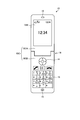
- FIG. 2 is a front view showing a schematic configuration of the portable communication device of the present invention shown in FIG.
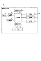
- FIG. 3 is a block diagram showing a schematic configuration of functions of the mobile communication device shown in FIG.
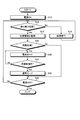
- FIG. 4 is a flowchart showing an example of the processing operation of the mobile communication device.
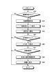
- FIG. 5 is a flowchart showing an example of processing operation of the mobile communication device.
- FIG. 6 is an explanatory diagram illustrating an example of an image displayed on the display unit of the mobile communication device.
- FIG. 7 is an explanatory diagram illustrating an example of an image displayed on the display unit of the mobile communication device.
- FIG. 1 is an explanatory diagram showing a schematic configuration of a communication system of the present invention having a portable communication device of the present invention.
- FIG. 2 is a front view showing a schematic configuration of the portable communication device of the present invention shown
- FIG. 8 is an explanatory diagram illustrating an example of an image displayed on the display unit of the mobile communication device.
- FIG. 9 is an explanatory diagram illustrating an example of an image displayed on the display unit of the mobile communication device.
- FIG. 10 is a flowchart showing an example of the processing operation of the mobile communication device.
- FIG. 11 is an explanatory diagram illustrating an example of an image displayed on the display unit of the mobile communication device.
- a mobile phone will be described as an example of the mobile communication device.
- the application target of the present invention is not limited to the mobile phone, and can be used for various communication devices having a call function.
- the present invention can be applied to PHS (Personal Handy-phone System), PDA, etc. as portable communication devices.
- the portable communication device can also be used for a dedicated crime prevention device having a communication function.
- a fixed terminal can also be used as a rescue side communication device (to be described later) constituting the communication system of the present invention.
- FIG. 1 is an explanatory diagram showing a schematic configuration of a communication system of the present invention having a portable communication device of the present invention.
- a communication system 1 shown in FIG. 1 includes a GPS satellite 2, a communication network 3, a server 6, a fixed terminal 7, a fixed telephone 9, and a plurality of mobile communication devices 10, 10a, 10b.
- the GPS satellite 2 is a satellite that transmits (provides) position information of the communication device to a communication device (communication terminal, communication device) having a communication function of GPS (Global Positioning System). Although only one GPS satellite 2 is shown in FIG. 1, the number of GPS satellites 2 (mainly three and four) necessary for specifying the position of the communication device is arranged.
- the plurality of GPS devices 2 output GPS signals (location information and time information of the GPS satellites 2) necessary for specifying the location information of the communication device.
- the communication device acquires its own position information by acquiring and analyzing the GPS signal output from the GPS satellite 2. The analysis may be performed by the communication device itself or may be performed by the external server 6.
- the communication network 3 is composed of a plurality of base stations, exchanges, and wired communication lines.
- the communication network 3 performs information communication between a communication device and another communication device using a wired or wireless communication line.
- the communication network 3 can use various communication methods as long as communication can be performed between communication devices. For example, communication may be performed using a satellite line.
- the server 6 has various data such as map information and information (telephone number, address) for identifying each communication device, and communicates with the communication device via the communication network 3 to supply various information.
- the server 6 also receives various types of information such as position information and GPS signals from the communication device and communicates information to other communication devices based on the information, and also relays information.
- the fixed terminal 7 is a fixed information terminal having an information communication function such as a PC (Personal Computer), and is connected to the communication network 3 by wire or wireless. Information is transmitted to and received from other communication devices via the communication network 3.
- the fixed telephone 8 is a telephone device connected to the communication network 3 via a wired telephone line.
- the mobile communication devices 10, 10 a, and 10 b are communication terminals that perform wireless communication with the communication network 3.
- the mobile communication device 10 transmits a signal such as an audio signal to the communication network 3 and receives a signal such as an audio signal from the communication network 3.
- Each mobile communication terminal is assigned and stored with a unique telephone number and terminal number. The configuration of the mobile communication devices 10, 10a, 10b will be described later.
- the communication system 1 is configured as described above.
- the mobile communication device 10 when a call operation is input to the mobile communication device 10 by a user's operation, the mobile communication device 10 sends a call signal and information of a communication destination telephone number to the communication network 3.
- the communication network 3 searches for the mobile communication device 10 to which the input communication destination telephone number is assigned, and notifies the communication destination mobile communication device 10 of an incoming call. Thereafter, the communication system 1 performs communication via the communication network 3 when a call start operation is input from the mobile communication device 10 that is the communication destination. That is, the communication system 1 performs communication between the mobile communication devices 10 by transmitting and receiving information via the communication network 3.
- the communication system 1 can communicate not only with the information communication between the mobile communication devices 10 but also with the mobile communication device 10 and the server 6, the mobile communication device 10 and the fixed terminal 7, and the mobile communication device 10 and the fixed phone 9. it can.
- communication between communication terminals is not limited to voice communication, and also transmits and receives data.
- the mobile communication device 10 constituting the communication system 1 can also acquire position information from the GPS satellite 2.
- FIG. 1 only one server 6, fixed terminal 7, and fixed telephone 9 are shown, and only three mobile communication devices 10 (10, 10a, 10b) are shown. 1 can be composed of a large number of servers 6, fixed terminals 7, fixed telephones 9, and portable communication devices 10.
- FIG. 2 is a front view showing a schematic configuration of the mobile communication device shown in FIG.
- the mobile communication device 10 is a mobile phone having a wireless communication function.
- the mobile communication device 10 is a foldable mobile phone in which a housing 10C is configured to be openable and closable by a first housing 10CA and a second housing 10CB.
- FIG. 2 shows a state where the mobile communication device 10 is opened.
- the casing 10C of the mobile communication terminal 10 is foldable, but the shape of the casing is not particularly limited.
- the casing can be in various forms, for example, a slide type, a sacroid type, a revolver type, a straight type, or the like.
- the first housing 10CA is provided with a main display 12M shown in FIG. 2 as a display unit.
- the main display 12M displays, as a predetermined image, a standby screen when the mobile communication device 10 is waiting for reception, or a menu image used to assist the operation of the mobile communication device 10.
- the first housing 10CA is provided with a receiver 16 that emits a voice when the mobile communication device 10 is talking.
- the second casing 10CB is provided with a plurality of operation keys 13 for inputting characters at the time of making a telephone number of the other party to call, mail creation, etc., and selection and determination of menus and screens displayed on the main display 12M
- a direction and determination key 14 is provided for easily executing scrolling and the like.
- the operation key 13 and the direction / decision key 14 constitute an operation unit 28 (see FIG. 3) of the mobile communication device 10.
- the second casing 10CB is provided with a microphone 15 that receives voice when the mobile communication device 10 is talking.
- first casing 10CA and the second casing 10CB are connected by a hinge 18. Accordingly, the first housing 10CA and the second housing 10CB are configured to rotate together around the hinge 18 so as to rotate in a direction away from each other and a direction approaching each other.
- the mobile communication device 10 opens, and when the first housing 10CA and the second housing 10CB rotate in a direction approaching each other, mobile communication The device 10 closes.
- FIG. 3 is a block diagram showing a schematic configuration of functions of the mobile communication device shown in FIG.
- the mobile communication device 10 includes a main control unit 22, a storage unit 24, a communication unit 26, an operation unit 28, an audio processing unit 30, a display unit 32, a display control unit 33, A GPS communication unit 34 and a security switch 36 are provided.
- the main control unit 22 is a processing unit that centrally controls the overall operation of the mobile communication device 10, for example, a CPU (Central Processing Unit). That is, the communication unit 26, the display unit, and the like so that various processes of the mobile communication device 10 are executed in an appropriate procedure according to the operation of the operation unit 28 and the software stored in the storage unit 24 of the mobile communication device 10. 32 and the like are controlled.
- the main control unit 22 executes processing based on programs (for example, operating system programs, application programs, etc.) stored in the storage unit 24. Further, the main control unit 22 can execute a plurality of programs (applications, software) in parallel.
- the storage unit 24 stores application programs and data used for processing in the main control unit 22. Specifically, as an application program, an application program that performs outgoing / incoming call processing, an application program that processes a crime prevention operation, an application program that processes a rescue operation, or an application program that transmits / receives mail Etc. are saved. As data, image data, audio data, dictionary data for character conversion, address book data, and the like are stored. In addition, a conversion table used in an application program for transmitting and receiving character information during a call is also provided.
- the communication unit 26 establishes a radio signal line by the CDMA method or the LTE method with the base station via the channel assigned by the base station of the communication network 3 described above, and performs telephone communication and information with the base station. Communicate. For this reason, the user can make a call with a desired partner through communication by the communication unit 26.
- the operation unit 28 includes, for example, an operation key 13 to which various functions such as a power key, a call key, a numeric key, a character key, and a call key are assigned, and a direction and determination key 14. When these keys are input by a user operation, the operation unit 28 generates a signal corresponding to the operation content. The generated signal is input to the main controller 22 as a user instruction.
- the audio processing unit 30 executes processing of an audio signal input to the microphone 15 and an audio signal output from the receiver 16.
- the display unit 32 includes a display panel (such as the main display 12M described above) configured by a liquid crystal display (LCD, Liquid Crystal Display), an organic EL (Organic Electro-Luminescence) panel, and the like.
- a display panel such as the main display 12M described above
- LCD Liquid Crystal Display
- organic EL Organic Electro-Luminescence
- the GPS communication unit 34 is a communication unit that receives a GPS signal transmitted from the GPS satellite 2. In addition, the GPS communication unit 34 calculates the latitude and longitude of the mobile communication device 10 from the received GSP signal, and sends information on the calculated latitude and longitude to the main control unit 22. The GPS communication unit 34 acquires GPS signals from a plurality of GPS satellites 2, and the distance from each GPS satellite 2 depending on the time difference between the time information included in the GPS signals and the acquired time information, the strength of the received radio waves, and the like. Is calculated. The GPS communication unit 34 calculates its own position by analyzing the distance from the GPS satellite 2 and the position information of each GPS satellite 2.
- the security switch 36 is a switch that can be switched ON and OFF by a user operation.
- the security switch 36 sends ON or OFF information to the main control unit 22.
- As the security switch 36 a switch whose position is changed by pulling or pushing can be used.
- As the crime prevention switch 36 a switch that is detachable from the housing 11 and that is connected to the housing 11 is turned on, and when it is detached from the housing 11, it is turned off. Can do.
- FIG. 4 is a flowchart showing an example of the processing operation of the mobile communication device.
- the mobile communication device 10 performs an operation in the crime prevention mode when a predetermined condition is satisfied by processing a program of an application for processing a crime prevention operation stored in the storage unit 24 by the main control unit 22. .
- the mobile communication device 10 is in a state in which the power is turned off, that is, the power supply to each unit is stopped and no image is displayed on the display unit 32. From this state, the mobile communication device 10 turns on the power as step S12. Specifically, the main control unit 22 turns on the power when the user presses the power button of the operation unit 28 or when the power-on operation is set by a timer or the like. When the instruction is detected, the power is turned on. That is, the main control unit 22 starts supplying power to each unit and activates various processing functions. Note that the main control unit 22 executes only a minimum function when the power is OFF.
- the main control unit 22 reads out an application program for processing the crime prevention operation from the storage unit 24 and activates an application for processing the crime prevention operation.
- the main control unit 22 turns on the power in step S12, the main control unit 22 starts the process of the crime prevention operation.
- the mobile communication device 10 determines whether it is in a standby state in step S14.
- the standby state is a state waiting for satisfying a user operation input or a preset condition (a state where a so-called standby screen is displayed). That is, the standby state is a state in which no applications other than programs that are always activated are not activated.
- step S14 determines in step S14 that it is not in a standby state (No)
- step S14 determines in step S14 that it is not in the standby state, it is in a state in which any application is being executed, and therefore the currently executing application (email transmission / reception, telephone call, website browsing) processing Execute.
- the main control unit 22 proceeds to step S14 and determines again whether it is in a standby state.
- the main control unit 22 determines in step S14 that it is in a standby state (Yes), it acquires position information as step S18. That is, the main control unit 22 communicates with the GPS satellite 2 by the GPS communication unit 34 and acquires its position information. Further, the main control unit 22 acquires map information including dangerous area information along with acquisition of its own position information.
- the acquisition method of map information is not specifically limited.
- the mobile communication device 10 may store the data in the storage unit 24 and read the data, or may acquire the data from an external storage device (server 6) or the like via the communication unit 26. At this time, the main control unit 22 may acquire the map information on the basis of the acquired own position information (for example, so as to include the own position information). Note that the main control unit 22 may detect an area in which the main control unit 22 is located by communication with the base station, and read or acquire map information in advance.
- the main control unit 22 determines whether it is a dangerous area in step S20. That is, the main control unit 22 determines whether or not its own position information acquired in step S18 is included in the dangerous area (dangerous area, dangerous area) (whether it is in the dangerous area).
- the danger area is the information of the area (area) acquired together with the map information. It is the area where the crime, the accident occurred, the security area, the dark area, the low traffic area, and the crime. It is an area that is more likely to be involved in dangerous matters such as other areas.
- a risk level is set according to the area. In the present embodiment, the degree of risk is set to four levels of “less than low”, “low”, “medium”, and “high”.
- step S20 determines in step S20 that it is not a dangerous area (No), that is, its own position information is not included in the dangerous area (outside the dangerous area), it proceeds to step S28. If the main control unit 22 determines in step S20 that it is a dangerous area (Yes), that is, its own position information is included in the dangerous area, the main control unit 22 sets a warning mode in step S22. The alert mode will be described later.
- the main control part 22 will determine whether it is out of a danger area as step S24, if warning mode is performed by step S22. More specifically, the main control unit 22 acquires its own position information in the same manner as in step S18 as step S24, and then collates its own position information with the information on the dangerous area. It is determined whether it is outside the danger zone, that is, whether it is outside the danger zone.
- Step S24 determines that it is not out of the dangerous area in Step S24 (No), that is, it is in the dangerous area, it proceeds to Step S22. That is, the main control unit 22 repeats the processes of step S22 and step S24 until it determines that it is outside the danger zone.
- step S24 determines in step S24 that it is out of the danger zone (Yes), that is, it is not in the danger zone, it sets the normal mode in step S26.
- the normal mode is a state that is not a warning mode. Thereafter, the main control unit 22 proceeds to step S28.
- the main control unit 22 determines whether or not to turn off the power as step S28 when it is determined No in step S20 and when the process of step S26 is completed. That is, the main control unit 22 determines whether there is an instruction to turn off the power and end the driving of the mobile communication device 10. Here, the main control unit 22 determines that an instruction to end is input when the power button of the operation unit 28 is pressed for a certain period of time or when the power-off operation is set by a timer or the like. If the main control unit 22 determines in step S28 that the power is not turned off (No), that is, it has not detected an instruction to turn off the power, the main control unit 22 proceeds to step S14 and repeats the above processing. If the main control unit 22 determines in step S28 that the power is off (Yes), that is, it has detected an instruction to turn off the power, the main control unit 22 performs a process of turning off the power and ends the process.
- the mobile communication device 10 determines whether the mobile communication device 10 is in the danger zone based on the position information of the mobile phone 10 and the map information including the danger zone information. Run the mode.
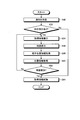
- FIG. 5 is a flowchart showing an example of processing operation of the mobile communication device.
- 6 to 9 are explanatory diagrams illustrating examples of images displayed on the display unit of the mobile communication device.
- the main control unit 22 lowers the threshold value of the battery (battery, power supply unit) so that it can be used for a longer time than usual.
- lowering the battery threshold means lowering at least one of the remaining battery level, voltage value, and current value of the battery being used, resulting in a lower battery level and lower voltage value.
- the mobile communication device 10 can be used even when the current value decreases. Thereby, the user can use the mobile communication device 10 for a longer time.
- the main control unit 22 notifies by voice that the vehicle has entered the dangerous area.
- the main control unit 22 determines whether the degree of risk is low or higher as step S30. That is, the main control unit 22 determines whether the danger level setting of the dangerous area including the acquired position information (position where the person is present) is low or higher, that is, low, medium, high (not less than low). ). If the main control unit 22 determines in step S30 that the degree of risk is not lower or higher (No), that is, the degree of risk is lower than low, the main control unit 22 ends the process. That is, the main control unit 22 ends the process only by notifying the fact that the battery threshold has been lowered and the danger zone has been entered as a warning mode.
- map information is acquired in step S32.
- the map information acquired in step S32 is map information including information such as roads and building arrangements.
- the map information may be obtained by reading the map information from an area where the map information is stored or temporarily stored.
- map information including the dangerous area information may be map information that can determine at least whether the position is the dangerous area, that is, information associated with the area (coordinates) of the dangerous area. There is no need for information such as road and building layout.
- the main control unit 22 After acquiring the map information in step S32, the main control unit 22 displays the map and route in step S34. That is, the main control unit 22 calculates a route to exit from the dangerous area based on its own position information, dangerous area information, and map information acquired in step S32. Thereafter, the main control unit 22 superimposes the calculated route and its position on the map information (synthesizes each information), creates an image, and causes the display unit 32 to display the created image.
- the main control unit 22 causes the display unit 32 to display an image 50 as shown in FIG.
- the image 50 includes a map 52.
- the map 52 displays road and building information for both the safe area 54 and the dangerous area 56.
- the safe area 54 is an area that is not a dangerous area.
- the boundary line between the safety area 54 and the danger area 56 is partitioned by a line.
- the main control unit 22 may display the safety area 54 and the dangerous area 56 in different colors. Further, the main control unit 22 may display the danger area 56 darker (or brighter) than the safety area 54 so that the danger area 56 becomes more conspicuous. That is, the main control unit 22 may display the safety area 54 and the dangerous area 56 with different brightness.
- the main controller 22 also displays its own position information (user's current position) 58 as a dot. Further, the main control unit 22 displays a route 60 from the current position to the safety area 54 with a line.
- the route 60 can be various routes depending on the setting, but it is preferable to display the shortest route or the route that can be determined to be the safest. By displaying the shortest route, the user can be moved to the safe area 54 in a short time. Further, by displaying the route that can be determined to be the safest, the risk of being involved in a crime, an accident, or the like can be reduced.
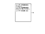
- the main control unit 22 After displaying the map and the route in step S34, the main control unit 22 performs notification (that is, sending an emergency signal) to the designated destination in step S36.
- the designated destination is a communication device of a preset person, facility, or organization such as a guardian, a parent, a police station, or a school.
- the main control unit 22 notifies the designated destination by voice or message that the mobile communication terminal 10 is in the dangerous area (the user is in the dangerous area).
- the main control part 22 should just send the image 70 as shown in FIG.
- the image 70 shown in FIG. 7 is composed of a message “The user has entered the dangerous area. Please urge the user to leave the dangerous area.” And the user's position information “User position: XX”.
- the message, the display method of the user's location information, and the text are not limited to this, and any configuration may be used as long as the user has entered the danger zone and can notify the user's location.
- the main control unit 22 sends the image 70 to the designated communication device via the communication unit 26.
- the terminal (server 6) of the security system can also be designated.
- step S34 and step S36 may be performed in the reverse order, and may be performed simultaneously.
- the main control unit 22 determines whether the degree of risk is medium or higher as step S38. That is, it is determined whether the danger level setting of the dangerous area including the acquired position information (position where the person is present) is medium or higher, that is, medium or high. If the main control unit 22 determines in step S38 that the degree of risk is not medium or higher (No), that is, the degree of risk is low, the main control unit 22 ends the process.
- step S40 a message is displayed in step S40. That is, the main control part 22 displays a message on the display part 32 in addition to map information as step S40. Specifically, the main control unit 22 causes the display unit 32 to display an image 80 shown in FIG.
- the image 80 has a map 82 and a message 84 composed of character information.
- the map 82 is basically the same map as the map 52 displayed in the image 50 of FIG. 6 described above.
- the message 84 is a sentence "This is a dangerous area. Please exit the dangerous area according to the map guide.”
- the message 84 is not limited to the text of the present embodiment, and may be a text requesting movement from the dangerous area to the safe area.
- the main control unit 22 displays an image 80 every 5 minutes.
- the main control part 22 will determine whether a risk is high as step S42, after complete
- the main control unit 22 determines that the degree of risk is high (Yes) in step S42, the main control unit 22 acquires information on one or more safe places as step S44.
- the safe place is a safe place, that is, a place that can serve as an evacuation place even in the dangerous area.
- police boxes, convenience stores, shops, buildings where security guards are stationed The main control unit 22 can acquire a safe place by various methods. Specifically, the main control unit 22 can acquire by a method similar to the map information described above.
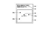
- the main control part 22 will display on a map as step S46, if the information of a safe place is acquired at step S44. Specifically, the main control unit 22 causes the display unit 32 to display an image 90 shown in FIG. In addition, when there are a plurality of safe places, the main control unit 22 selects a place having the shortest distance to the place, or gives priority to a place that can pass through a relatively low risk area. It is preferable to select them. Further, a route to a safe place may be displayed.
- the image 90 has a map 92 and a message 94 composed of character information.
- the position 96 of the user and the safe places 98a, 98b, 98c are displayed.
- the safe places 98a, 98b, and 98c are each indicated by a red dot.
- the message 94 is a sentence “The safe place is a red dot on the following map.” That is, the message 94 is an explanatory text of a method for identifying a safe place.
- the main control unit 22 displays an image 90 every 5 minutes.
- the main control unit 22 ends the security mode process.
- the main control unit 22 repeats the process of the crime prevention mode shown in FIG. 5 until shifting to the normal mode.
- the mobile communication device 10 when the mobile communication device 10 detects that the mobile communication device 10 has entered the dangerous area, the mobile communication device 10 can reduce the risk of being involved in a crime, an accident, or the like by executing the alert mode. Further, by changing the process to be executed according to the danger level of the dangerous area, it is possible to execute a warning according to the danger level.
- the mobile communication device 10 can efficiently escape from the dangerous area by displaying the map information and the route 60 for escaping from the dangerous area on the display unit 32, and is involved in a crime, an accident, or the like. Fear can be further reduced.
- the mobile communication device 10 can move to a safe place without any hesitation when the danger is approaching by displaying information on the safe place in the dangerous area on the map. Thereby, the risk of getting involved in crimes, accidents, etc. can be further reduced.
- the processing to be executed is changed in accordance with the degree of risk in order to efficiently and sufficiently execute warning, but the present invention is not limited to this. Further, the processing performed according to each risk level may be performed according to any risk level.
- the mobile communication device 10 has a shooting function or a recording function
- the warning mode is executed or when a predetermined risk level is achieved
- images are taken every predetermined time or moving images are shot. May be started, or recording may be started.
- the mobile communication device 10 is not limited to the route to the safe area, and may display the route to the safe place. Thereby, it can move to a safe place safely in a short time.
- FIG. 10 is a flowchart illustrating an example of the processing operation of the mobile communication device
- FIG. 11 is an explanatory diagram illustrating an example of an image displayed on the display unit of the mobile communication device.
- the main control unit 22 of the mobile communication device 10b receives a notification in step S50. That is, the control unit 22 receives information that has entered the danger area from the mobile communication device 10 a via the communication unit 26.
- the processing of each unit of the mobile communication device 10 b is basically performed unless otherwise specified.
- the main control part 22 will determine whether there exists a corresponding instruction
- step S52 determines in step S52 that there is no response instruction (No), that is, an instruction not to perform a rescue operation has been input, or no operation has been input for a certain period of time, the process proceeds to step S64.
- step S52 determines in step S52 that there is a response instruction (Yes), that is, if an instruction to perform a rescue operation is input, the main control unit 22 displays the acquired information in step S54 and displays the map in step S56. . Note that the main control unit 22 causes the display unit 32 to display the acquired information and map as one image 100, as shown in FIG.
- the image 100 includes a message 102, a map 104, an item 106, and an item 108.
- the message 102 is the sentence "The crime prevention buzzer has operated at the red dot below. Please rescue.
- the subject's physical characteristics are XX. Please refer to the photograph.”
- the map 104 displays the position 110 of the mobile communication device 10a, the own position 112, and the route 114 from the own position 112 to the position 110 of the mobile communication device 10a.
- the main control unit 22 uses the GPS communication unit 36 to detect its own position information, and acquires the position information and map information of the mobile communication device 10a. Then, based on the acquired position information of the mobile communication device 10a and the map information, a travel route from the mobile device 10a to the mobile communication device 10a is calculated. In this way, the acquired or calculated positions 110 and 112 and the route 114 are displayed on the map 104 in an overlapping manner.
- the map information and the location information of the mobile communication device 10a may be acquired together with the notification received in step S50, or may be acquired through separate communication. Further, the map information may use data stored in its own storage unit 24 as described above.
- the item 106 is an item associated with a sentence “contact a parent”, and the item 108 is an item associated with a sentence “view a photo”.
- each of the items 106 and 108 has a shortcut function.
- the main control unit 22 makes a call without displaying the telephone number on the communication device registered as the parent communication device. Further, when the item 108 is selected (clicked), the main control unit 22 displays a photograph.
- the main control part 22 will acquire partner position information as step S58, if a map is displayed by step S56. That is, the position information of the mobile communication device 10a is acquired (updated) again.
- the main control unit 22 acquires the position information of the other party in step S58, the main control unit 22 also acquires (updates) its own position information in step S60.
- the main control unit 22 determines whether or not the situation has been solved in step S62. That is, the main control unit 22 determines whether the user of the mobile communication device 10a has been rescued.
- the main control unit 22 can be set to determine whether the user has been rescued based on various criteria. For example, if the position information detected in step S58 is outside the danger zone, it can be set to determine that the rescue has been performed. Further, if the position information detected in step S58 and the position information detected in step S60 have the same coordinates, it can be set to determine that the other party has been found and rescued. Moreover, it can also be set as the determination which rescued if the operator of the portable communication apparatus 10a or the portable communication apparatus 10b input predetermined
- step S62 determines in step S62 that the situation has not been resolved (No)
- the main control unit 22 proceeds to step S54 and repeats the above processing. Further, when determining that the situation has been solved (Yes) in Step S62, the main control unit 22 deletes the acquired information as Step S64, that is, deletes the information acquired in Step S50, and ends the process.
- the mobile communication device 10 (in the present embodiment, the mobile communication device 10b) can perform the above-described processing by executing the application for processing the rescue operation. That is, by displaying the route to the mobile communication device 10a based on the location information of itself, the location information of the mobile communication device 10a that sent the notification, and the map information, the mobile communication device 10a You can reach the place where the owner is. Moreover, since the main control unit 22 repeats the processing from step S54 to step S62 until the situation is resolved, each position information can be updated, and even in a state of moving relative to each other, in a shorter time. It is possible to reach the place where the owner of the portable communication device 10a is. In addition, by displaying the position as an image, it is possible to notify a person who does not notice the sound. That is, even if the screaming is not heard, it is possible to reach the place where the owner of the mobile communication device 10a is present.
- the mobile communication device 10a is accurately detected. Can find the owner of Furthermore, when the situation is solved, the leakage of personal information can be suppressed by deleting the information. Further, as in the present embodiment, personal information can be prevented from leaking by not displaying the telephone number directly, displaying it as text information, and not displaying it when making a call.
- the personal information not to be displayed is not limited to a telephone number, but can be applied to an e-mail address or the like. Moreover, it is preferable to set such information to be untransferable. Thereby, it can suppress that personal information leaks.
- the position information of the rescue target can be accurately known based on the GPS signal, a person who is closer to the rescue target can quickly go to rescue. In addition, since it is possible to prevent the person from going to the rescue in reality, the rescue can be performed efficiently.
- the rescue communication device is a portable communication device.
- the present invention is not limited to this, and a fixed communication device, specifically, a fixed terminal and a fixed telephone can also be used. In the case of a fixed telephone, it is preferable to display an image using the FAX function.
- the map information may be stored in the rescue communication device so that only the position information is notified.
- the communication system 1 uses one of the servers 6 as a service server 6 that provides these security systems.
- the user of the mobile communication device 10a designates the server 6 as the designation destination.
- the server 6 establishes a communication device (contact station fixed phone, fixed terminal, police officer, mobile communication device owned by a patrol guard, convenience store fixed) for each area set as a dangerous area. (Telephone, fixed terminal) information.
- the mobile communication device 10a when the mobile communication device 10a receives the information indicating that the mobile communication device 10a is in the dangerous area, the mobile communication device 10a transmits a notification to the communication device that is in the dangerous area and serves as a contact. In this way, the server 6 can temporarily receive the information from the portable communication device 10a and transmit the information all at once to the communication devices around the point, so that the person to be rescued can be rescued in a shorter time. .
- the server 6 periodically receives position information from the mobile communication device 10 set as the rescue communication device, and receives a notification from the mobile communication device 10a. You may make it notify the rescue request also with respect to the mobile communication apparatus in a fixed range. Note that the communication system 1 can notify the rescue request to all of the mobile communication devices 10 in a predetermined area, but is set in advance in order to more securely protect personal information. You may make it send the notification of a rescue request to the portable communication apparatus 10 in a fixed area
- the server 6 can accurately specify the position of the portable communication device that has made a rescue request, and can select the rescue-side communication device from that position. As a result, the number and range of communication devices to which the server 6 performs notification can be narrowed down, and highly effective notification can be performed. Further, by narrowing down the number of communication devices, it is possible to further reduce the risk of leakage of personal information.
- the server 6 transmits, as the first notification, the position information of the mobile communication device 10a and a notification for confirming whether it can be supported (whether it will be rescued), and then transmits a compatible notification.
- the personal information may be transmitted only to the communication device. Thereby, it can suppress transmitting personal information to the communication apparatus more than necessary.
- information is transmitted from the mobile communication device 10 (or 10a) when entering any dangerous area, but the present invention is not limited to this.
- a notification requesting rescue (notification of occurrence of an emergency situation) may be made to a designated destination.
- the load of processing and monitoring as the communication system 1 increases, the same operation may be performed when the crime prevention switch 36 is turned on even outside the dangerous area.
- the determination of the risk level may be switched between the ON state and the OFF state of the crime prevention switch 36. That is, even when the crime prevention switch 36 is in the OFF position, it may be determined that the risk level is low, and when the security switch 36 is in the ON state, it may be determined that the risk level is high.
- dangerous areas can be added, changed, or deleted according to user settings.
- an appropriate dangerous area can be set according to a person who owns the mobile communication device, for example, a child or an elderly person.
- the risk level determination based on the owner may be performed on the risk zone. For example, if the owner of the mobile communication device is prohibited from drinking alcohol, the bar town may be set as a dangerous area. Accordingly, even when the user takes an inappropriate action, it is possible to be notified that it is dangerous.
- the main control unit 22 determines whether or not the user is in the dangerous area by using voice information in addition to the position information. For example, by receiving voice, it can be determined whether you are in a pachinko parlor. When using audio information, it may be determined based on whether a sound unique to the place has been received or the volume of the audio. Thus, a position can be specified with higher accuracy by combining position information and other information.
- the information on the dangerous area may be appropriately acquired from an external storage device such as the server 6 or the like, but is updated every certain period (from one month to two months) and, as described above, the user However, it is preferable to adjust in consideration of the season and time. Thereby, a dangerous area can be set more appropriately. In addition, communication costs and battery consumption can be reduced. It is preferable that the dangerous area is set not by a portable communication device to be protected but by a communication device set as a guardian. Thereby, it can suppress that a setting is changed arbitrarily.
- the mobile terminal device may include both an application program for processing a crime prevention operation and an application program for processing a rescue operation, but includes only one of them. Also good. That is, the mobile terminal device may have both a function of transmitting an emergency signal (requesting rescue) and a function of receiving an emergency signal (rescuing), but the side requesting rescue. It is good also as a structure provided only with the function of only the function of the side which performs only the function of the side which rescues. If both functions are provided, the function to be used (executed) may be selected depending on the situation.
- the communication system and the portable communication device according to the present invention are useful for use as a communication device having a crime prevention function.
Landscapes
- Engineering & Computer Science (AREA)
- Computer Networks & Wireless Communication (AREA)
- Signal Processing (AREA)
- Business, Economics & Management (AREA)
- Emergency Management (AREA)
- Human Computer Interaction (AREA)
- Telephone Function (AREA)
- Telephonic Communication Services (AREA)
- Alarm Systems (AREA)
Abstract
A communication system comprises: a mobile communication apparatus that includes a positional information acquiring unit for acquiring the positional information of the mobile communication apparatus and that further includes a communication unit for transmitting the positional information and an emergency signal; and a communication apparatus that, when having detected that the emergency signal and positional information of the mobile communication apparatus have been transmitted from the mobile communication apparatus, causes a display unit to display both the positional information of the mobile communication apparatus and the positional information of the communication apparatus. The communication apparatus is caused to display the position of the mobile communication apparatus as described above, thereby enhancing the crime prevention effect and hence reducing the possibility of getting caught up in a crime.
Description
本発明は、端末との通信を行う携帯通信装置及び携帯通信装置を有する通信システムに関する。
The present invention relates to a portable communication device that performs communication with a terminal and a communication system having the portable communication device.
近年、携帯電話機等の携帯通信装置及び携帯通信装置を用いた通信システムには、種々の機能が搭載されている。この機能の1つとして防犯機能がある。
In recent years, mobile communication devices such as mobile phones and communication systems using mobile communication devices have various functions. One of these functions is a crime prevention function.
例えば、特許文献1には、所定の操作が行われることで、警報音を発生させる警報付き携帯電話機が記載されている。また、特許文献2には、地図上の所定領域で発生した犯罪に関する情報に基づく所定領域犯罪情報を通知する犯罪情報通知装置が記載されている。さらに、特許文献3には、国内及び現地の所定の機関から安全情報・災害情報を収集し、収集した安全情報の信用度を算出し、信用度が所定の値以上の安全情報のみをユーザーへ提供する安全情報提供装置が記載されている。また、特許文献3には、危険な領域に近づくとアラームで通知する方法も提案されている。
For example, Patent Literature 1 describes a mobile phone with an alarm that generates an alarm sound when a predetermined operation is performed. Patent Document 2 describes a crime information notification device for notifying predetermined area crime information based on information related to crimes occurring in a predetermined area on a map. Further, Patent Document 3 collects safety information / disaster information from predetermined domestic and local institutions, calculates the reliability of the collected safety information, and provides only the safety information whose reliability is a predetermined value or more to the user. A safety information providing device is described. Patent Document 3 also proposes a method of notifying by an alarm when approaching a dangerous area.
しかしながら、特許文献1に記載された装置のように、警報音を発生させても、その地域が人通りの少ない地域では、音声を出力しても助けてくれる人が存在しない場合がある。
However, even if an alarm sound is generated as in the device described in Patent Document 1, there may be no person who can help even if the sound is output in an area where there is little traffic.
また、特許文献2に記載の装置は、犯罪情報を取得することで、地域の犯罪状況を知ることができる。しかしながら、特許文献2に記載の装置は、ユーザーが端末を用いて情報を確認する必要があり、ユーザーが確認しないと犯罪情報を得ることができない、また、ユーザーの警戒心が低いと有効に活用できない。
Also, the device described in Patent Document 2 can know the crime situation in the area by acquiring crime information. However, the device described in Patent Document 2 requires the user to confirm information using a terminal, and cannot be obtained effectively unless the user confirms the crime information. Can not.
また、特許文献3に記載の装置は、危険な領域に近づいたらアラームで通知されるため、危険な領域に近づかないようにすることができる。しかしながら、このようにアラームが発生しても、危険な領域を通過する必要がある場合もあり、そのような場合には、アラームで警告されても適切に防犯することが困難である。
Further, since the device described in Patent Document 3 is notified by an alarm when approaching a dangerous area, it can be prevented from approaching the dangerous area. However, even if an alarm occurs in this way, it may be necessary to pass through a dangerous area. In such a case, it is difficult to appropriately prevent crime even if the alarm is warned.
本発明は、上記に鑑みてなされたものであって、防犯効果をより高くすることができ、犯罪に巻き込まれる恐れをより低減することができる通信システム及び携帯通信装置を提供することを目的とする。
This invention is made in view of the above, Comprising: It aims at providing the communication system and portable communication apparatus which can make a crime prevention effect higher, and can reduce the possibility of getting involved in a crime more. To do.
本発明は、通信システムであって、自身の位置情報を取得する位置情報取得部及び位置情報と緊急信号を発信する通信部を備える携帯通信装置と、前記携帯通信装置から前記緊急信号と前記携帯通信装置の位置情報が発信されていることを検出したら、前記携帯通信装置の位置情報と自身の位置情報とを表示部に表示させる通信装置と、を備えることを特徴とする。
The present invention is a communication system, a mobile communication device including a location information acquisition unit that acquires its own location information and a communication unit that transmits location information and an emergency signal, and the emergency signal and the mobile phone from the mobile communication device. And a communication device that displays the position information of the portable communication device and its own position information on a display unit when it is detected that the position information of the communication device is transmitted.
ここで、前記通信装置は、携帯型の通信装置であることが好ましい。
Here, the communication device is preferably a portable communication device.
また、前記通信装置は、前記携帯通信装置の位置情報と前記自身の位置情報とを地図上に表示させ、かつ、自身の位置から前記携帯通信装置の位置への移動経路を表示させることが好ましい。
Moreover, it is preferable that the communication device displays the position information of the mobile communication device and the position information of the mobile communication device on a map, and displays a movement path from the position of the mobile communication device to the position of the mobile communication device. .
また、他の通信装置と通信を行うサーバをさらに有し、前記サーバは、前記携帯通信装置から前記緊急信号が発信されていることを検出したら、前記携帯通信装置の位置情報に基づいて、前記緊急信号及び前記携帯通信装置の位置情報を送信する通信装置を決定し、決定した通信装置に前記緊急信号及び前記携帯通信装置の位置情報を送信することが好ましい。
Further, the server further includes a server that communicates with another communication device, and when the server detects that the emergency signal is transmitted from the mobile communication device, the server is configured based on the location information of the mobile communication device. Preferably, a communication device that transmits an emergency signal and position information of the portable communication device is determined, and the emergency signal and position information of the portable communication device are transmitted to the determined communication device.
また、前記サーバは、前記携帯通信装置及び前記通信装置から送信される位置情報に基づいて、当該通信装置に地図情報を送信することが好ましい。
Further, it is preferable that the server transmits map information to the communication device based on the position information transmitted from the mobile communication device and the communication device.
また、前記携帯通信装置は、緊急スイッチをさらに有し、前記緊急スイッチに予め設定された操作が入力されたら、前記通信部から前記緊急信号を発信させることが好ましい。
In addition, it is preferable that the mobile communication device further includes an emergency switch, and when the preset operation is input to the emergency switch, the emergency signal is transmitted from the communication unit.
また、前記通信装置は、前記携帯通信装置の所有者の情報を取得し、個人情報が漏洩しない方式で表示させることが好ましい。
Further, it is preferable that the communication device acquires the information of the owner of the mobile communication device and displays the information in a manner that does not leak personal information.
本発明は、携帯通信装置であって、他の携帯通信装置と通信する通信部と、自身の位置情報を検出する位置情報取得部と、地図情報を取得する地図情報取得部と、画像を表示させる画像表示部と、前記他の携帯通信装置から緊急信号が出力されていることを検出したら、前記通信部を介して前記他の携帯通信装置の位置情報を取得し、前記地図情報取得部で取得した地図情報に、前記位置情報取得部で取得した自身の位置情報と、前記他の携帯通信装置の位置情報を重ねた画像を前記表示部に表示させる制御部と、を有することを特徴とする。
The present invention relates to a mobile communication device that communicates with other mobile communication devices, a location information acquisition unit that detects its own location information, a map information acquisition unit that acquires map information, and an image display If it is detected that an emergency signal is output from the image display unit and the other mobile communication device, the position information of the other mobile communication device is acquired via the communication unit, and the map information acquisition unit A control unit that causes the display unit to display an image obtained by superimposing the position information acquired by the position information acquisition unit on the acquired map information and the position information of the other mobile communication device. To do.
また、前記制御部は、前記地図情報に、前記自身の位置から前記携帯通信装置の位置への移動経路を重ねて表示させることが好ましい。
In addition, it is preferable that the control unit displays a moving route from the own position to the position of the mobile communication device on the map information.
また、前記地図情報取得部は、前記位置情報取得部で取得した位置情報に基づいて、当該位置情報を含む地図情報を外部の記憶装置から取得することが好ましい。
Further, it is preferable that the map information acquisition unit acquires map information including the position information from an external storage device based on the position information acquired by the position information acquisition unit.
また、前記位置情報取得部は、全地球測位システムにより、位置情報を取得することが好ましい。
Further, it is preferable that the position information acquisition unit acquires position information by a global positioning system.
また、前記制御部は、前記通信部により前記他の携帯通信装置の所有者の情報を取得し、取得した所有者の情報を個人情報が漏洩しない方式で前記表示部に表示させることが好ましい。
In addition, it is preferable that the control unit acquires information on an owner of the other portable communication device by the communication unit, and displays the acquired information on the owner on the display unit in a manner that personal information does not leak.
また、前記制御部は、前記他の携帯通信装置の位置情報が予め設定された条件を満たしたら、取得した所有者の情報を消去することが好ましい。
Further, it is preferable that the control unit erases the acquired owner information when the position information of the other portable communication device satisfies a preset condition.
また、前記通信部は、サーバを介して前記他の携帯通信装置の情報を取得することが好ましい。
Moreover, it is preferable that the communication unit acquires information of the other portable communication device via a server.
上述した課題を解決し、目的を達成するために、本発明は、携帯通信装置であって、他の通信装置と通信する通信部と、自身の位置情報を検出する位置情報取得部と、危険区域の情報を含む地図情報を取得する地図情報取得部と、画像を表示させる画像表示部と、前記自身の位置情報と、前記地図情報とに基づいて、前記自身が前記危険区域内にいることを検出したら、自身の位置情報と、前記危険区域よりも外の区域に到達する経路を前記地図情報に重ねて前記表示部に表示させる制御部と、を有することが好ましい。
In order to solve the above-described problems and achieve the object, the present invention provides a portable communication device, a communication unit that communicates with another communication device, a position information acquisition unit that detects its own position information, Based on the map information acquisition unit that acquires the map information including the information of the area, the image display unit that displays the image, the position information of the own area, and the map information, the self is in the dangerous area It is preferable to have a control unit that displays its own position information and a route that reaches an area outside the dangerous area on the map information on the map unit.
また、前記制御部は、前記自身が前記危険区域内にいることを検出したら、さらに、他の通信機器に自身の位置情報を送信することが好ましい。
In addition, when the control unit detects that it is in the dangerous area, it is preferable that the control unit further transmits its position information to another communication device.
また、前記地図情報取得部は、前記危険区域内にある安全な場所の情報を取得し、前記制御部は、前記安全な場所の情報を前記地図情報にさらに重ねて表示させることが好ましい。
In addition, it is preferable that the map information acquisition unit acquires information on a safe place in the dangerous area, and the control unit displays the information on the safe place further superimposed on the map information.
本発明にかかる通信システム及び携帯通信装置は、防犯効果をより高くすることができ、犯罪に巻き込まれる恐れをより低減することができるという効果を奏する。
The communication system and the portable communication device according to the present invention can increase the crime prevention effect and can further reduce the risk of being involved in a crime.
以下、本発明につき図面を参照しつつ詳細に説明する。なお、以下の説明により本発明が限定されるものではない。また、以下の説明における構成要素には、当業者が容易に想定できるもの、実質的に同一のもの、いわゆる均等の範囲のものが含まれる。以下においては、携帯通信装置の一例として携帯電話機を例として説明するが、本発明の適用対象は携帯電話機に限定されるものではなく、通話機能を備える種々の通信機器に用いることができる。例えば、携帯通信装置としては、PHS(Personal Handy-phone System)、PDA等に対しても本発明は適用できる。また、携帯通信装置として、通信機能を備える専用の防犯装置にも用いることができる。また、本発明の通信システムを構成する後述する救出側の通信装置には、固定端末も用いることができ、例えば、固定式の電話機、複合機、PC(Personal Computer)にも用いることができる。
Hereinafter, the present invention will be described in detail with reference to the drawings. The present invention is not limited to the following description. In addition, constituent elements in the following description include those that can be easily assumed by those skilled in the art, those that are substantially the same, and those in a so-called equivalent range. In the following, a mobile phone will be described as an example of the mobile communication device. However, the application target of the present invention is not limited to the mobile phone, and can be used for various communication devices having a call function. For example, the present invention can be applied to PHS (Personal Handy-phone System), PDA, etc. as portable communication devices. The portable communication device can also be used for a dedicated crime prevention device having a communication function. In addition, a fixed terminal can also be used as a rescue side communication device (to be described later) constituting the communication system of the present invention.
図1は、本発明の携帯通信装置を有する本発明の通信システムの概略構成を示す説明図である。図1に示す通信システム1は、GPS衛星2と、通信網3と、サーバ6と、固定端末7と、固定電話9と、複数の携帯通信装置10、10a、10bとで構成されている。
FIG. 1 is an explanatory diagram showing a schematic configuration of a communication system of the present invention having a portable communication device of the present invention. A communication system 1 shown in FIG. 1 includes a GPS satellite 2, a communication network 3, a server 6, a fixed terminal 7, a fixed telephone 9, and a plurality of mobile communication devices 10, 10a, 10b.
GPS衛星2は、GPS(Global Positioning System、全地球測位システム)の通信機能を備える通信装置(通信端末、通信機器)に、該通信機器の位置情報を送信(提供)する衛星である。なお、図1でGPS衛星2を1つのみ示したが、GPS衛星2は、通信装置の位置を特定するために必要な数(主として3つ、4つ)が配置されている。複数のGPS装置2は、通信装置の位置情報の特定に必要なGPS信号(GPS衛星2の位置情報や時間情報)を出力する。なお、通信装置は、GPS衛星2から出力されるGPS信号を取得し解析することで自身の位置情報を取得する。なお、解析は、通信装置自身が行ってもよく、また外部のサーバ6にて行ってもよい。
The GPS satellite 2 is a satellite that transmits (provides) position information of the communication device to a communication device (communication terminal, communication device) having a communication function of GPS (Global Positioning System). Although only one GPS satellite 2 is shown in FIG. 1, the number of GPS satellites 2 (mainly three and four) necessary for specifying the position of the communication device is arranged. The plurality of GPS devices 2 output GPS signals (location information and time information of the GPS satellites 2) necessary for specifying the location information of the communication device. The communication device acquires its own position information by acquiring and analyzing the GPS signal output from the GPS satellite 2. The analysis may be performed by the communication device itself or may be performed by the external server 6.
通信網3は、複数の基地局や、交換機や、有線の通信回線で構成されている。通信網3は、有線、無線の通信回線を用いて通信装置と他の通信装置との間での情報通信を行う。通信網3は、通信装置間で通信を行うことができれば、種々の通信方法を用いることができる。例えば、衛星回線を利用して通信を行ってもよい。
The communication network 3 is composed of a plurality of base stations, exchanges, and wired communication lines. The communication network 3 performs information communication between a communication device and another communication device using a wired or wireless communication line. The communication network 3 can use various communication methods as long as communication can be performed between communication devices. For example, communication may be performed using a satellite line.
サーバ6は、地図情報、各通信装置を特定する情報(電話番号、アドレス)種々のデータを有し、通信網3を介して通信装置と通信し、種々の情報を供給する。また、サーバ6は、通信装置から位置情報やGPS信号等の各種情報を受信し、その情報に基づいて、他の通信機器に情報を通信する、情報の中継も行う。固定端末7は、PC(Personal Computer)等の情報通信機能を備える固定型の情報端末であり、有線、無線により通信網3と接続されている。通信網3を介して、他の通信装置と情報の送受信を行う。固定電話8は、有線の電話回線を介して通信網3と接続された電話装置である。
The server 6 has various data such as map information and information (telephone number, address) for identifying each communication device, and communicates with the communication device via the communication network 3 to supply various information. The server 6 also receives various types of information such as position information and GPS signals from the communication device and communicates information to other communication devices based on the information, and also relays information. The fixed terminal 7 is a fixed information terminal having an information communication function such as a PC (Personal Computer), and is connected to the communication network 3 by wire or wireless. Information is transmitted to and received from other communication devices via the communication network 3. The fixed telephone 8 is a telephone device connected to the communication network 3 via a wired telephone line.
携帯通信装置10、10a、10bは、通信網3との間で無線通信を行う通信端末である。携帯通信装置10は、音声信号等の信号を通信網3に送信し、通信網3から音声信号等の信号を受信する。また、それぞれの携帯通信端末には、固有の電話番号、端末番号が割り当てられ、記憶されている。携帯通信装置10、10a、10bの構成については、後ほど説明する。
The mobile communication devices 10, 10 a, and 10 b are communication terminals that perform wireless communication with the communication network 3. The mobile communication device 10 transmits a signal such as an audio signal to the communication network 3 and receives a signal such as an audio signal from the communication network 3. Each mobile communication terminal is assigned and stored with a unique telephone number and terminal number. The configuration of the mobile communication devices 10, 10a, 10b will be described later.
通信システム1は、以上のような構成である。通信システム1は、ユーザーの操作により携帯通信装置10に発信操作が入力されると、携帯通信装置10から通信網3に対して、発信信号と通信先の電話番号の情報が送られる。通信網3は、入力された通信先の電話番号が割り当てられている携帯通信装置10を検索し、通信先の携帯通信装置10に着信を通知する。その後、通信システム1は、通信先の携帯通信装置10で通話開始の操作が入力されたら、通信網3を介して通信を行う。つまり、通信システム1は、通信網3を介して情報の送受信を行うことで、携帯通信装置10間で通信を行う。また、通信システム1は、携帯通信装置10間の情報通信だけでなく、携帯通信装置10とサーバ6、携帯通信装置10と固定端末7、携帯通信装置10と固定電話9でも通信を行うことができる。なお、通信システム1は、通信端末間での通信は、音声通信に限定されず、データの送受信も行う。また、通信システム1を構成する携帯通信装置10は、GPS衛星2から位置情報を取得することもできる。また、図1では、サーバ6と、固定端末7と、固定電話9とをそれぞれ1つのみ、携帯通信装置10は、3つのみ(10、10a、10b)を図示しているが、通信システム1は、多数の、サーバ6と、固定端末7と、固定電話9と、携帯通信装置10で構成することができる。
The communication system 1 is configured as described above. In the communication system 1, when a call operation is input to the mobile communication device 10 by a user's operation, the mobile communication device 10 sends a call signal and information of a communication destination telephone number to the communication network 3. The communication network 3 searches for the mobile communication device 10 to which the input communication destination telephone number is assigned, and notifies the communication destination mobile communication device 10 of an incoming call. Thereafter, the communication system 1 performs communication via the communication network 3 when a call start operation is input from the mobile communication device 10 that is the communication destination. That is, the communication system 1 performs communication between the mobile communication devices 10 by transmitting and receiving information via the communication network 3. Further, the communication system 1 can communicate not only with the information communication between the mobile communication devices 10 but also with the mobile communication device 10 and the server 6, the mobile communication device 10 and the fixed terminal 7, and the mobile communication device 10 and the fixed phone 9. it can. In the communication system 1, communication between communication terminals is not limited to voice communication, and also transmits and receives data. Further, the mobile communication device 10 constituting the communication system 1 can also acquire position information from the GPS satellite 2. In FIG. 1, only one server 6, fixed terminal 7, and fixed telephone 9 are shown, and only three mobile communication devices 10 (10, 10a, 10b) are shown. 1 can be composed of a large number of servers 6, fixed terminals 7, fixed telephones 9, and portable communication devices 10.
次に、携帯通信装置10、10a、10bについて説明する。なお、携帯通信装置10と、携帯通信装置10aと、携帯通信装置10bとは、同様の装置構成であるので、以下、携帯通信装置10を用いて説明する。図2は、図1に示す携帯通信装置の概略構成を示す正面図である。携帯通信装置10は、無線通信機能を備えた携帯電話機である。携帯通信装置10は、筐体10Cが第1筐体10CAと第2筐体10CBとで開閉可能に構成された、折り畳み式の携帯電話機である。なお、図2は、携帯通信装置10を開いた状態である。なお、本実施形態では、携帯通信端末10の筐体10Cを折り畳み式としたが、筐体の形状は特に限定されない。筐体は種々の形態とすることができ、例えば、スライド式、サクロイド式、リボルバー式、ストレート式等でもよい。
Next, the mobile communication devices 10, 10a, and 10b will be described. In addition, since the portable communication apparatus 10, the portable communication apparatus 10a, and the portable communication apparatus 10b are the same apparatus structures, it demonstrates using the portable communication apparatus 10 below. FIG. 2 is a front view showing a schematic configuration of the mobile communication device shown in FIG. The mobile communication device 10 is a mobile phone having a wireless communication function. The mobile communication device 10 is a foldable mobile phone in which a housing 10C is configured to be openable and closable by a first housing 10CA and a second housing 10CB. FIG. 2 shows a state where the mobile communication device 10 is opened. In the present embodiment, the casing 10C of the mobile communication terminal 10 is foldable, but the shape of the casing is not particularly limited. The casing can be in various forms, for example, a slide type, a sacroid type, a revolver type, a straight type, or the like.
第1筐体10CAには、表示部として、図2に示すメインディスプレイ12Mが設けられる。メインディスプレイ12Mは、所定の画像として、携帯通信装置10が受信を待機している状態のときに待ち受け画面を表示したり、携帯通信装置10の操作を補助するために用いられるメニュー画像を表示したりする。また、図2に示すように、第1筐体10CAには、携帯通信装置10の通話時に音声を発するレシーバ16が設けられている。
The first housing 10CA is provided with a main display 12M shown in FIG. 2 as a display unit. The main display 12M displays, as a predetermined image, a standby screen when the mobile communication device 10 is waiting for reception, or a menu image used to assist the operation of the mobile communication device 10. Or Further, as shown in FIG. 2, the first housing 10CA is provided with a receiver 16 that emits a voice when the mobile communication device 10 is talking.
第2筐体10CBには、通話する相手の電話番号やメール作成時等に文字を入力するための操作キー13が複数設けられ、また、メインディスプレイ12Mに表示されるメニューの選択及び決定や画面のスクロール等を容易に実行するための方向及び決定キー14が設けられる。なお、操作キー13及び方向及び決定キー14は、携帯通信装置10の操作部28(図3参照)を構成する。また、第2筐体10CBには、携帯通信装置10の通話時に音声を受け取るマイク15が設けられる。
The second casing 10CB is provided with a plurality of operation keys 13 for inputting characters at the time of making a telephone number of the other party to call, mail creation, etc., and selection and determination of menus and screens displayed on the main display 12M A direction and determination key 14 is provided for easily executing scrolling and the like. The operation key 13 and the direction / decision key 14 constitute an operation unit 28 (see FIG. 3) of the mobile communication device 10. In addition, the second casing 10CB is provided with a microphone 15 that receives voice when the mobile communication device 10 is talking.
また、第1筐体10CAと第2筐体10CBとは、ヒンジ18で連結されている。これによって、第1筐体10CA及び第2筐体10CBは、ヒンジ18を中心としてともに回動して、互いに遠ざかる方向及び互いに接近する方向に回動できるように構成される。第1筐体10CAと第2筐体10CBとが互いに遠ざかる方向に回動すると携帯通信装置10が開き、第1筐体10CAと第2筐体10CBとが互いに接近する方向に回動すると携帯通信装置10が閉じる。
Further, the first casing 10CA and the second casing 10CB are connected by a hinge 18. Accordingly, the first housing 10CA and the second housing 10CB are configured to rotate together around the hinge 18 so as to rotate in a direction away from each other and a direction approaching each other. When the first housing 10CA and the second housing 10CB rotate in a direction away from each other, the mobile communication device 10 opens, and when the first housing 10CA and the second housing 10CB rotate in a direction approaching each other, mobile communication The device 10 closes.
次に、携帯通信装置10の機能と制御部との関係を説明する。図3は、図2に示す携帯通信装置の機能の概略構成を示すブロック図である。図3に示すように携帯通信装置10は、主制御部22と、記憶部24と、通信部26と、操作部28と、音声処理部30と、表示部32と、表示制御部33と、GPS通信部34と、防犯スイッチ36とを有する。
Next, the relationship between the function of the mobile communication device 10 and the control unit will be described. FIG. 3 is a block diagram showing a schematic configuration of functions of the mobile communication device shown in FIG. As shown in FIG. 3, the mobile communication device 10 includes a main control unit 22, a storage unit 24, a communication unit 26, an operation unit 28, an audio processing unit 30, a display unit 32, a display control unit 33, A GPS communication unit 34 and a security switch 36 are provided.
主制御部22は、携帯通信装置10の全体的な動作を統括的に制御する処理部、例えばCPU(Central Processing Unit)である。すなわち、携帯通信装置10の各種の処理が、操作部28の操作や携帯通信装置10の記憶部24に保存されるソフトウェアに応じて適切な手順で実行されるように、通信部26、表示部32等の動作を制御する。主制御部22は、記憶部24に保存されているプログラム(例えば、オペレーティングシステムプログラム、アプリケーションプログラム等)に基づいて処理を実行する。また、主制御部22は、複数のプログラム(アプリケーション、ソフトウェア)を並列で実行することができる。
The main control unit 22 is a processing unit that centrally controls the overall operation of the mobile communication device 10, for example, a CPU (Central Processing Unit). That is, the communication unit 26, the display unit, and the like so that various processes of the mobile communication device 10 are executed in an appropriate procedure according to the operation of the operation unit 28 and the software stored in the storage unit 24 of the mobile communication device 10. 32 and the like are controlled. The main control unit 22 executes processing based on programs (for example, operating system programs, application programs, etc.) stored in the storage unit 24. Further, the main control unit 22 can execute a plurality of programs (applications, software) in parallel.
記憶部24には、主制御部22での処理に利用されるアプリケーションのプログラムやデータが保存されている。具体的には、アプリケーションのプログラムとして、発信、着信、通話処理を行うアプリケーションのプログラム、防犯動作を処理するアプリケーションのプログラムや、救出動作を処理するアプリケーションのプログラムや、メールの送受信を行うアプリケーションのプログラム等が保存されている。また、データとしては、画像データ、音声データ、文字変換のための辞書データ、アドレス帳データ等が記憶されている。また、上述した通話中に文字情報を送受信するためのアプリケーションのプログラムで使用する変換テーブルも備えている。
The storage unit 24 stores application programs and data used for processing in the main control unit 22. Specifically, as an application program, an application program that performs outgoing / incoming call processing, an application program that processes a crime prevention operation, an application program that processes a rescue operation, or an application program that transmits / receives mail Etc. are saved. As data, image data, audio data, dictionary data for character conversion, address book data, and the like are stored. In addition, a conversion table used in an application program for transmitting and receiving character information during a call is also provided.
通信部26は、上述した通信網3の基地局によって割り当てられるチャネルを介し、基地局との間でCDMA方式やLTE方式などによる無線信号回線を確立し、基地局との間で電話通信及び情報通信を行う。このため、ユーザーは、通信部26による通信により所望の相手との通話が可能となる。
The communication unit 26 establishes a radio signal line by the CDMA method or the LTE method with the base station via the channel assigned by the base station of the communication network 3 described above, and performs telephone communication and information with the base station. Communicate. For this reason, the user can make a call with a desired partner through communication by the communication unit 26.
操作部28は、例えば、電源キー、通話キー、数字キー、文字キー、発信キーなど、各種の機能が割り当てられた操作キー13と、方向及び決定キー14と、で構成される。操作部28は、これらのキーがユーザーの操作により入力されると、その操作内容に対応する信号を発生させる。そして、発生した信号は、ユーザーの指示として主制御部22へ入力される。
The operation unit 28 includes, for example, an operation key 13 to which various functions such as a power key, a call key, a numeric key, a character key, and a call key are assigned, and a direction and determination key 14. When these keys are input by a user operation, the operation unit 28 generates a signal corresponding to the operation content. The generated signal is input to the main controller 22 as a user instruction.
音声処理部30は、マイク15に入力される音声信号やレシーバ16から出力される音声信号の処理を実行する。
The audio processing unit 30 executes processing of an audio signal input to the microphone 15 and an audio signal output from the receiver 16.
表示部32は、液晶ディスプレイ(LCD、Liquid Crystal Display)や、有機EL(Organic Electro-Luminescence)パネルなどで構成された表示パネル(上述したメインディスプレイ12M等)を備え、主制御部22から表示制御部33を介して供給される映像データに応じた映像、画像データに応じた画像を表示パネルに表示させる。
The display unit 32 includes a display panel (such as the main display 12M described above) configured by a liquid crystal display (LCD, Liquid Crystal Display), an organic EL (Organic Electro-Luminescence) panel, and the like. A video corresponding to the video data supplied via the unit 33 and an image corresponding to the image data are displayed on the display panel.
GPS通信部34は、GPS衛星2から発信されるGPS信号を受信する通信部である。また、GPS通信部34は、受信したGSP信号から携帯通信装置10の緯度経度を算出し、算出した緯度経度の情報を主制御部22に送る。GPS通信部34は、複数のGPS衛星2からGPS信号を取得し、GPS信号に含まれる時間情報と取得した時間情報との時間差や、受信した電波の強度等によりそれぞれのGPS衛星2からの距離を算出する。GPS通信部34は、GPS衛星2からの距離と各GPS衛星2の位置情報を解析することで、自身の位置を算出する。
The GPS communication unit 34 is a communication unit that receives a GPS signal transmitted from the GPS satellite 2. In addition, the GPS communication unit 34 calculates the latitude and longitude of the mobile communication device 10 from the received GSP signal, and sends information on the calculated latitude and longitude to the main control unit 22. The GPS communication unit 34 acquires GPS signals from a plurality of GPS satellites 2, and the distance from each GPS satellite 2 depending on the time difference between the time information included in the GPS signals and the acquired time information, the strength of the received radio waves, and the like. Is calculated. The GPS communication unit 34 calculates its own position by analyzing the distance from the GPS satellite 2 and the position information of each GPS satellite 2.
防犯スイッチ36は、ユーザーの操作によりONとOFFとが切り替えられるスイッチである。防犯スイッチ36は、ONまたはOFFの情報を主制御部22に送る。防犯スイッチ36としては、引っ張ったり、押したりすることで位置が変化するスイッチを用いることができる。なお、防犯スイッチ36としては、筐体11に対して、着脱可能な部材で、筐体11と連結している状態はON状態、筐体11から離脱した状態ではOFF状態となるスイッチを用いることができる。
The security switch 36 is a switch that can be switched ON and OFF by a user operation. The security switch 36 sends ON or OFF information to the main control unit 22. As the security switch 36, a switch whose position is changed by pulling or pushing can be used. As the crime prevention switch 36, a switch that is detachable from the housing 11 and that is connected to the housing 11 is turned on, and when it is detached from the housing 11, it is turned off. Can do.
次に、図4を用いて、携帯通信装置10の動作について説明する。ここで、図4は、携帯通信装置の処理動作の一例を示すフロー図である。まず、携帯通信装置10は、記憶部24に記憶されている、防犯動作を処理するアプリケーションのプログラムを主制御部22で処理することにより、所定の条件が満たされたら、防犯モードの動作を行う。
Next, the operation of the mobile communication device 10 will be described with reference to FIG. Here, FIG. 4 is a flowchart showing an example of the processing operation of the mobile communication device. First, the mobile communication device 10 performs an operation in the crime prevention mode when a predetermined condition is satisfied by processing a program of an application for processing a crime prevention operation stored in the storage unit 24 by the main control unit 22. .
まず、携帯通信装置10は、電源がOFFとなっている、つまり各部への電力の供給が停止している状態で、表示部32にも画像が表示されていない状態である。この状態から、携帯通信装置10は、ステップS12として電源をONにする。具体的には、主制御部22は、ユーザーによって、操作部28の電源ボタンが押下された場合、また、タイマー等で電源ON動作が設定された時間になった場合等、電源をONにする指示を検出したら、電源をONにする。つまり、主制御部22は、各部への電力の供給を開始し、各種処理機能を起動させる。なお、主制御部22も電源がOFF状態の場合は、最小限の機能のみを実行するようにする。また、主制御部22は、防犯動作を処理するアプリケーションプログラムを記憶部24から読み出し、防犯動作を処理するアプリケーションを起動させる。主制御部22は、ステップS12で電源をONにしたら、防犯動作の処理を開始する。
First, the mobile communication device 10 is in a state in which the power is turned off, that is, the power supply to each unit is stopped and no image is displayed on the display unit 32. From this state, the mobile communication device 10 turns on the power as step S12. Specifically, the main control unit 22 turns on the power when the user presses the power button of the operation unit 28 or when the power-on operation is set by a timer or the like. When the instruction is detected, the power is turned on. That is, the main control unit 22 starts supplying power to each unit and activates various processing functions. Note that the main control unit 22 executes only a minimum function when the power is OFF. In addition, the main control unit 22 reads out an application program for processing the crime prevention operation from the storage unit 24 and activates an application for processing the crime prevention operation. When the main control unit 22 turns on the power in step S12, the main control unit 22 starts the process of the crime prevention operation.
携帯通信装置10は、ステップS12で電源をONにしたら、ステップS14として、待ち受け状態であるかを判定する。ここで、待ち受け状態とは、ユーザーの操作の入力、または、予め設定した条件を)満たすことを待っている状態(いわゆる待ち受け画面を表示させている状態)である。つまり、待ち受け状態とは、常時起動されているプログラム等を除いたアプリケーションが起動されてない状態である。
When the mobile communication device 10 is turned on in step S12, the mobile communication device 10 determines whether it is in a standby state in step S14. Here, the standby state is a state waiting for satisfying a user operation input or a preset condition (a state where a so-called standby screen is displayed). That is, the standby state is a state in which no applications other than programs that are always activated are not activated.
主制御部22は、ステップS14で待ち受け状態ではない(No)と判定したら、ステップS16として、アプリケーションの処理を実行する。主制御部22は、ステップS14で待ち受け状態ではないと判定する場合は、何らかのアプリケーションを実行している状態であるため、当該実行中のアプリケーション(メールの送受信や、通話、ウェブサイト閲覧)の処理を実行する。主制御部22は、ステップS16で処理を実行したら、ステップS14に進み、再び待ち受け状態であるかを判定する。
If the main control unit 22 determines in step S14 that it is not in a standby state (No), it executes application processing in step S16. If the main control unit 22 determines in step S14 that it is not in the standby state, it is in a state in which any application is being executed, and therefore the currently executing application (email transmission / reception, telephone call, website browsing) processing Execute. After executing the process in step S16, the main control unit 22 proceeds to step S14 and determines again whether it is in a standby state.
また、主制御部22は、ステップS14で待ち受け状態である(Yes)と判定したら、ステップS18として、位置情報を取得する。つまり、主制御部22は、GPS通信部34によりGPS衛星2と通信を行い、自身の位置情報を取得する。また、主制御部22は、自身の位置情報の取得とともに、危険区域の情報が含まれた地図情報を取得する。なお、地図情報の取得方法は特に限定されない。例えば、携帯通信装置10は、記憶部24に記憶しておきそのデータを読み出しても、通信部26を介して外部の記憶装置(サーバ6)等から取得してもよい。なお、この時、主制御部22は、取得した自身の位置情報を基準として(例えば、自身の位置情報を含むように)、地図情報を取得すればよい。なお、主制御部22は、基地局との通信により、自身がいる領域を検出しておき、予め地図情報を読み出して、または取得しておいてもよい。
If the main control unit 22 determines in step S14 that it is in a standby state (Yes), it acquires position information as step S18. That is, the main control unit 22 communicates with the GPS satellite 2 by the GPS communication unit 34 and acquires its position information. Further, the main control unit 22 acquires map information including dangerous area information along with acquisition of its own position information. In addition, the acquisition method of map information is not specifically limited. For example, the mobile communication device 10 may store the data in the storage unit 24 and read the data, or may acquire the data from an external storage device (server 6) or the like via the communication unit 26. At this time, the main control unit 22 may acquire the map information on the basis of the acquired own position information (for example, so as to include the own position information). Note that the main control unit 22 may detect an area in which the main control unit 22 is located by communication with the base station, and read or acquire map information in advance.
主制御部22は、ステップS18で位置情報を取得し、かつ地図情報も取得したら、ステップS20で危険区域であるかを判定する。つまり、主制御部22は、ステップS18で取得した自身の位置情報が危険区域(危険地域、危険領域)に含まれているか(自身が危険区域内にいるか)を判定する。ここで、危険区域とは、地図情報と共に取得される区域(地域)の情報であり、過去に犯罪、事故が発生した区域、治安の悪い区域、暗い区域、人通りの少ない区域であり、犯罪等の危険なことに巻き込まれる可能性が他の区域よりも高い区域である。また、危険区域の情報には、区域によって危険度も設定されている。本実施形態では、危険度は、「低未満」、「低」、「中」、「高」の4段階に設定されている。
If the main control unit 22 acquires the position information in step S18 and also acquires the map information, the main control unit 22 determines whether it is a dangerous area in step S20. That is, the main control unit 22 determines whether or not its own position information acquired in step S18 is included in the dangerous area (dangerous area, dangerous area) (whether it is in the dangerous area). Here, the danger area is the information of the area (area) acquired together with the map information. It is the area where the crime, the accident occurred, the security area, the dark area, the low traffic area, and the crime. It is an area that is more likely to be involved in dangerous matters such as other areas. In addition, in the risk area information, a risk level is set according to the area. In the present embodiment, the degree of risk is set to four levels of “less than low”, “low”, “medium”, and “high”.
主制御部22は、ステップS20で危険区域ではない(No)、つまり、自身の位置情報が危険区域に含まれていない(危険区域外である)と判定したら、ステップS28に進む。また、主制御部22は、ステップS20で危険区域である(Yes)、つまり、自身の位置情報が危険区域に含まれていると判定したら、ステップS22として警戒モードとする。なお、警戒モードについては、後ほど説明する。
If the main control unit 22 determines in step S20 that it is not a dangerous area (No), that is, its own position information is not included in the dangerous area (outside the dangerous area), it proceeds to step S28. If the main control unit 22 determines in step S20 that it is a dangerous area (Yes), that is, its own position information is included in the dangerous area, the main control unit 22 sets a warning mode in step S22. The alert mode will be described later.
主制御部22は、ステップS22で警戒モードを実行したら、ステップS24として、危険区域外であるかを判定する。より具体的には、主制御部22は、ステップS24として、ステップS18と同様に自身の位置情報を取得し、その後、自身の位置情報と危険区域の情報とを照合し、自身の位置情報が危険区域外に含まれているか、つまり自身が危険区域外にいるかを判定する。
The main control part 22 will determine whether it is out of a danger area as step S24, if warning mode is performed by step S22. More specifically, the main control unit 22 acquires its own position information in the same manner as in step S18 as step S24, and then collates its own position information with the information on the dangerous area. It is determined whether it is outside the danger zone, that is, whether it is outside the danger zone.
主制御部22は、ステップS24で危険区域外ではない(No)、つまり、自身は危険区域内にいると判定したら、ステップS22に進む。つまり、主制御部22は、危険区域外であると判定するまで、ステップS22とステップS24との処理を繰り返す。
If the main control unit 22 determines that it is not out of the dangerous area in Step S24 (No), that is, it is in the dangerous area, it proceeds to Step S22. That is, the main control unit 22 repeats the processes of step S22 and step S24 until it determines that it is outside the danger zone.
また、主制御部22は、ステップS24で危険区域外である(Yes)、つまり、自身は危険区域内にいないと判定したら、ステップS26として、通常モードにする。ここで、通常モードとは、警戒モードではない状態である。主制御部22は、その後、ステップS28に進む。
If the main control unit 22 determines in step S24 that it is out of the danger zone (Yes), that is, it is not in the danger zone, it sets the normal mode in step S26. Here, the normal mode is a state that is not a warning mode. Thereafter, the main control unit 22 proceeds to step S28.
主制御部22は、ステップS20でNoと判定したら、また、ステップS26の処理が終了したら、ステップS28として、電源をOFFにするかを判定する。つまり、主制御部22は、電源をOFF、携帯通信装置10の駆動を終了する指示があるかを判定する。ここで、主制御部22は、操作部28の電源ボタンが一定時間押下されたら、また、タイマー等で電源OFF動作が設定された時間になったら、終了する指示が入力されたと判定する。主制御部22は、ステップS28で電源OFFではない(No)、つまり、電源をOFFにする指示を検出していないと判定したら、ステップS14に進み上記処理を繰り返す。また、主制御部22は、ステップS28で電源OFFである(Yes)、つまり、電源をOFFにする指示を検出したと判定したら、電源をOFFにする処理を行い、処理を終了する。
The main control unit 22 determines whether or not to turn off the power as step S28 when it is determined No in step S20 and when the process of step S26 is completed. That is, the main control unit 22 determines whether there is an instruction to turn off the power and end the driving of the mobile communication device 10. Here, the main control unit 22 determines that an instruction to end is input when the power button of the operation unit 28 is pressed for a certain period of time or when the power-off operation is set by a timer or the like. If the main control unit 22 determines in step S28 that the power is not turned off (No), that is, it has not detected an instruction to turn off the power, the main control unit 22 proceeds to step S14 and repeats the above processing. If the main control unit 22 determines in step S28 that the power is off (Yes), that is, it has detected an instruction to turn off the power, the main control unit 22 performs a process of turning off the power and ends the process.
このように、携帯通信装置10は、自身の位置情報と危険区域の情報を含む地図情報とに基づいて、自身が危険区域内にいるかを判定し、危険区域にいると判定した場合は、警戒モードを実行する。
As described above, the mobile communication device 10 determines whether the mobile communication device 10 is in the danger zone based on the position information of the mobile phone 10 and the map information including the danger zone information. Run the mode.
次に、図5、図6から図9を用いて、主制御部22が実行する警戒モードの一例について説明する。図5は、携帯通信装置の処理動作の一例を示すフロー図である。また、図6から図9は、それぞれ携帯通信装置の表示部に表示される画像の一例を示す説明図である。
Next, an example of the alert mode executed by the main control unit 22 will be described with reference to FIGS. 5 and 6 to 9. FIG. 5 is a flowchart showing an example of processing operation of the mobile communication device. 6 to 9 are explanatory diagrams illustrating examples of images displayed on the display unit of the mobile communication device.
まず、主制御部22は、警戒モードを実行すると、電池(バッテリー、電源部)の閾値を下げ、通常よりも長時間使用可能とする。なお、電池の閾値を下げるとは、使用している電池の使用可能な電池残量、電圧値、電流値の少なくとも1つの閾値を下げ、より電池残量が少ない状態、電圧値が低くなっても、電流値が低くなっても、携帯通信装置10を使用可能とする設定である。これにより、ユーザーは、携帯通信装置10をより長時間使用することができる。また、主制御部22は、警戒モードを実行すると、危険区域に入ったことを音声で通知する。
First, when executing the alert mode, the main control unit 22 lowers the threshold value of the battery (battery, power supply unit) so that it can be used for a longer time than usual. Note that lowering the battery threshold means lowering at least one of the remaining battery level, voltage value, and current value of the battery being used, resulting in a lower battery level and lower voltage value. In other words, the mobile communication device 10 can be used even when the current value decreases. Thereby, the user can use the mobile communication device 10 for a longer time. In addition, when executing the alert mode, the main control unit 22 notifies by voice that the vehicle has entered the dangerous area.
その後、主制御部22は、ステップS30として危険度が低以上であるかを判定する。つまり、主制御部22は、取得した自身の位置情報(自身がいる位置)が含まれる危険区域の危険度の設定が低以上、つまり、低、中、高であるか(低未満ではないか)を判定する。主制御部22は、ステップS30で、危険度が低以上ではない(No)、つまり危険度が低未満であると判定したら、そのまま処理を終了する。つまり、主制御部22は、警戒モードとして、電池の閾値を下げ危険区域に入ったことを音声で通知するのみで処理を終了する。
Thereafter, the main control unit 22 determines whether the degree of risk is low or higher as step S30. That is, the main control unit 22 determines whether the danger level setting of the dangerous area including the acquired position information (position where the person is present) is low or higher, that is, low, medium, high (not less than low). ). If the main control unit 22 determines in step S30 that the degree of risk is not lower or higher (No), that is, the degree of risk is lower than low, the main control unit 22 ends the process. That is, the main control unit 22 ends the process only by notifying the fact that the battery threshold has been lowered and the danger zone has been entered as a warning mode.
また、主制御部22は、ステップS30で、危険度が低以上である(Yes)、つまり、危険度が低、中、高のいずれかであると判定したら、ステップS32として、地図情報を取得する。ここで、ステップS32で取得される地図情報は、道や建物配置等の情報を含む地図情報である。なお、危険区域の情報を含む地図情報を使用可能な場合は、当該地図情報が記憶または一時的に記憶されている領域から地図情報を読み出すことで取得すればよい。また、新たに取得する場合は、通信部26を介して外部の記憶装置から、また記憶部24に記憶されているデータから地図情報を取得すればよい。なお、危険区域の情報を含む地図情報は、少なくともその位置が危険区域であるかを判定することができる地図情報であればよく、つまり、危険区域の領域(座標)が対応付けられた情報であればよく、道や建物の配置等の情報までは必要ない。
If the main control unit 22 determines in step S30 that the degree of risk is low or higher (Yes), that is, the degree of risk is low, medium, or high, map information is acquired in step S32. To do. Here, the map information acquired in step S32 is map information including information such as roads and building arrangements. In addition, when map information including information on the dangerous area can be used, the map information may be obtained by reading the map information from an area where the map information is stored or temporarily stored. Moreover, what is necessary is just to acquire map information from the external memory | storage device via the communication part 26, and the data memorize | stored in the memory | storage part 24 when acquiring newly. Note that the map information including the dangerous area information may be map information that can determine at least whether the position is the dangerous area, that is, information associated with the area (coordinates) of the dangerous area. There is no need for information such as road and building layout.
主制御部22は、ステップS32で地図情報を取得したら、ステップS34として、地図及びルートを表示させる。つまり、主制御部22は、自身の位置情報、危険区域の情報及びステップS32で取得した地図情報に基づいて、危険区域から出るためのルートを算出する。その後、主制御部22は、算出したルートと自身の位置を地図情報に重ね(各情報を合成し)、画像を作成し、作成した画像を表示部32に表示させる。
After acquiring the map information in step S32, the main control unit 22 displays the map and route in step S34. That is, the main control unit 22 calculates a route to exit from the dangerous area based on its own position information, dangerous area information, and map information acquired in step S32. Thereafter, the main control unit 22 superimposes the calculated route and its position on the map information (synthesizes each information), creates an image, and causes the display unit 32 to display the created image.
具体的には、主制御部22は、表示部32に図6に示すような、画像50を表示させる。画像50には、地図52が含まれている。この地図52は、安全区域54と危険区域56の両方の区域について道や建物の情報が表示されている。なお、安全区域54は、危険区域ではない区域である。また、安全区域54と危険区域56との境界線が線により仕切られている。また、主制御部22は、安全区域54と危険区域56と異なる色で表示させるようにしてもよい。また、主制御部22は、危険区域56がより目立つように、危険区域56を、安全区域54よりも暗く(または明るく)表示させてもよい。つまり、主制御部22は、安全区域54と危険な領域56とを異なる明るさで表示させてもよい。また、主制御部22は、自身の位置情報(ユーザーの現在位置)58も点で表示させる。さらに、主制御部22は、現在の位置から安全区域54までの経路60を線で表示させる。なお、経路60は、設定によって、種々の経路とすることができるが、最短経路、または最も安全と判定できる経路を表示させることが好ましい。最短経路を表示させることで、ユーザーを短時間で安全区域54に移動させることができる。また最も安全と判断できる経路を表示させることで、犯罪、事故等に巻き込まれるおそれをより少なくすることができる。
Specifically, the main control unit 22 causes the display unit 32 to display an image 50 as shown in FIG. The image 50 includes a map 52. The map 52 displays road and building information for both the safe area 54 and the dangerous area 56. The safe area 54 is an area that is not a dangerous area. In addition, the boundary line between the safety area 54 and the danger area 56 is partitioned by a line. The main control unit 22 may display the safety area 54 and the dangerous area 56 in different colors. Further, the main control unit 22 may display the danger area 56 darker (or brighter) than the safety area 54 so that the danger area 56 becomes more conspicuous. That is, the main control unit 22 may display the safety area 54 and the dangerous area 56 with different brightness. The main controller 22 also displays its own position information (user's current position) 58 as a dot. Further, the main control unit 22 displays a route 60 from the current position to the safety area 54 with a line. The route 60 can be various routes depending on the setting, but it is preferable to display the shortest route or the route that can be determined to be the safest. By displaying the shortest route, the user can be moved to the safe area 54 in a short time. Further, by displaying the route that can be determined to be the safest, the risk of being involved in a crime, an accident, or the like can be reduced.
主制御部22は、ステップS34で地図及びルートを表示させたら、ステップS36として、指定先に通知(つまり、緊急信号の発信)を行う。ここで、指定先とは、保護者、親、警察署、学校等の予め設定した人物、施設、機関の通信機器である。主制御部22は、指定先に、音声、メッセージにより、携帯通信端末10が危険区域内にある(ユーザーが危険区域内にいる)ことを通知する。ここで、主制御部22は、メッセージで通知する場合、図7に示すような画像70を送ればよい。図7に示す画像70は、「ユーザーが危険地域に入りました。ユーザーが危険地域から出るように促してください。」というメッセージと「ユーザーの位置:○○」というユーザーの位置情報とで構成される。なお、メッセージ、ユーザーの位置情報の表示方法、文章は、これに限定されず、ユーザーが危険区域に入ったことと、ユーザーの位置を通知することができれば、どのような構成でもよい。主制御部22は、通信部26を介して画像70を指定先の通信装置に送る。また、防犯システムの端末(サーバ6)も指定先とすることができる。なお、防犯システムの端末(サーバ6)に送信する場合は後ほど説明する。また、ステップS34とステップS36とは、逆の順番で行ってもよく、また同時に行ってもよい。
After displaying the map and the route in step S34, the main control unit 22 performs notification (that is, sending an emergency signal) to the designated destination in step S36. Here, the designated destination is a communication device of a preset person, facility, or organization such as a guardian, a parent, a police station, or a school. The main control unit 22 notifies the designated destination by voice or message that the mobile communication terminal 10 is in the dangerous area (the user is in the dangerous area). Here, when notifying by the message, the main control part 22 should just send the image 70 as shown in FIG. The image 70 shown in FIG. 7 is composed of a message “The user has entered the dangerous area. Please urge the user to leave the dangerous area.” And the user's position information “User position: XX”. Is done. The message, the display method of the user's location information, and the text are not limited to this, and any configuration may be used as long as the user has entered the danger zone and can notify the user's location. The main control unit 22 sends the image 70 to the designated communication device via the communication unit 26. The terminal (server 6) of the security system can also be designated. In addition, when transmitting to the terminal (server 6) of a crime prevention system, it demonstrates later. Moreover, step S34 and step S36 may be performed in the reverse order, and may be performed simultaneously.
主制御部22は、ステップS36の処理を終了したら、ステップS38として危険度が中以上であるかを判定する。つまり、取得した自身の位置情報(自身がいる位置)が含まれる危険区域の危険度の設定が中以上、つまり、中、高であるかを判定する。主制御部22は、ステップS38で、危険度が中以上ではない(No)、つまり危険度が低であると判定したら、そのまま処理を終了する。
After completing the process of step S36, the main control unit 22 determines whether the degree of risk is medium or higher as step S38. That is, it is determined whether the danger level setting of the dangerous area including the acquired position information (position where the person is present) is medium or higher, that is, medium or high. If the main control unit 22 determines in step S38 that the degree of risk is not medium or higher (No), that is, the degree of risk is low, the main control unit 22 ends the process.
また、主制御部22は、ステップS38で、危険度が中以上である(Yes)、つまり、危険度が中、高のいずれかであると判定したら、ステップS40として、メッセージを表示させる。つまり、主制御部22は、ステップS40として、地図情報に加え、メッセージを表示部32に表示させる。具体的には、主制御部22は、図8に示す画像80を表示部32に表示させる。ここで、画像80は、地図82と、文字情報で構成されたメッセージ84とを有する。ここで、地図82は、上述した図6の画像50に表示される地図52と基本的に同じ地図である。また、メッセージ84は、「ここは危険区域です。地図の案内に従って危険区域を抜けてください。」という文章である。なお、メッセージ84は、本実施形態の文章に限定されず、危険区域から安全区域への移動を要請する文章であればよい。また、主制御部22は、5分毎に、画像80を表示させる。
If the main control unit 22 determines in step S38 that the degree of risk is medium or higher (Yes), that is, the degree of risk is medium or high, a message is displayed in step S40. That is, the main control part 22 displays a message on the display part 32 in addition to map information as step S40. Specifically, the main control unit 22 causes the display unit 32 to display an image 80 shown in FIG. Here, the image 80 has a map 82 and a message 84 composed of character information. Here, the map 82 is basically the same map as the map 52 displayed in the image 50 of FIG. 6 described above. The message 84 is a sentence "This is a dangerous area. Please exit the dangerous area according to the map guide." The message 84 is not limited to the text of the present embodiment, and may be a text requesting movement from the dangerous area to the safe area. In addition, the main control unit 22 displays an image 80 every 5 minutes.
主制御部22は、ステップS40の処理を終了したら、ステップS42として危険度が高であるかを判定する。つまり、取得した自身の位置情報(自身がいる位置)が含まれる危険区域の危険度の設定が高であるかを判定する。主制御部22は、ステップS42で、危険度が高ではない(No)、つまり危険度が中であると判定したら、そのまま処理を終了する。
The main control part 22 will determine whether a risk is high as step S42, after complete | finishing the process of step S40. That is, it is determined whether or not the danger level setting of the danger area including the acquired position information (position where the person is present) is high. If the main control unit 22 determines in step S42 that the degree of risk is not high (No), that is, the degree of risk is medium, the main control unit 22 ends the process.
また、主制御部22は、ステップS42で、危険度が高である(Yes)と判定したら、ステップS44として、一または複数の安全な場所の情報を取得する。ここで、安全な場所とは、危険区域に含まれる中でも安全な場所、つまり、避難場所となりうる場所である。例えば、交番、コンビニ、商店、警備員が常駐しているビル等である。なお、主制御部22は、安全な場所を種々の方法で取得することができ、具体的には、上述した地図情報と同様の方法で取得することができる。
If the main control unit 22 determines that the degree of risk is high (Yes) in step S42, the main control unit 22 acquires information on one or more safe places as step S44. Here, the safe place is a safe place, that is, a place that can serve as an evacuation place even in the dangerous area. For example, police boxes, convenience stores, shops, buildings where security guards are stationed. The main control unit 22 can acquire a safe place by various methods. Specifically, the main control unit 22 can acquire by a method similar to the map information described above.
主制御部22は、ステップS44で安全な場所の情報を取得したら、ステップS46として、地図に表示する。具体的には、主制御部22は、図9に示す画像90を表示部32に表示させる。なお、主制御部22は、安全な場所が複数ある場合、最もその場所までの距離が短い場所を選定したり、或いは、危険度が比較的低い地域を通過していくことができる場所を優先して選定したりすることが好ましい。また、安全な場所までの経路を表示させてもよい。ここで、画像90は、地図92と、文字情報で構成されたメッセージ94とを有する。ここで、地図92には、ユーザーの位置96と、安全な場所98a、98b、98cが表示される。安全な場所98a、98b、98cは、それぞれ赤点で表示されている。なお、図示を省略したが、地図92には、安全区域と危険区域の境界線や、安全区域までの経路の表示も継続している。また、メッセージ94は、「安全な場所は下記の地図の赤点です。」という文章である。つまり、メッセージ94は、安全な場所の識別方法の説明文章である。また、主制御部22は、5分毎に、画像90を表示させる。主制御部22は、ステップS96の処理を終了したら、防犯モードの処理を終了する。なお、主制御部22は、通常モードに移行するまで、図5に示す防犯モードの処理を繰り返す。
The main control part 22 will display on a map as step S46, if the information of a safe place is acquired at step S44. Specifically, the main control unit 22 causes the display unit 32 to display an image 90 shown in FIG. In addition, when there are a plurality of safe places, the main control unit 22 selects a place having the shortest distance to the place, or gives priority to a place that can pass through a relatively low risk area. It is preferable to select them. Further, a route to a safe place may be displayed. Here, the image 90 has a map 92 and a message 94 composed of character information. Here, on the map 92, the position 96 of the user and the safe places 98a, 98b, 98c are displayed. The safe places 98a, 98b, and 98c are each indicated by a red dot. In addition, although illustration was abbreviate | omitted, on the map 92, the boundary line of a safe area and a dangerous area and the display to the route to a safe area are also continued. The message 94 is a sentence “The safe place is a red dot on the following map.” That is, the message 94 is an explanatory text of a method for identifying a safe place. Further, the main control unit 22 displays an image 90 every 5 minutes. When the process of step S96 is completed, the main control unit 22 ends the security mode process. The main control unit 22 repeats the process of the crime prevention mode shown in FIG. 5 until shifting to the normal mode.
このように、携帯通信装置10は、危険区域に入ったことを検出したら、警戒モードを実行することで、犯罪、事故等に巻き込まれる恐れを低減することができる。また、危険区域の危険度に応じて、実行する処理を変化させることで、危険度に応じた警戒を実行することができる。
As described above, when the mobile communication device 10 detects that the mobile communication device 10 has entered the dangerous area, the mobile communication device 10 can reduce the risk of being involved in a crime, an accident, or the like by executing the alert mode. Further, by changing the process to be executed according to the danger level of the dangerous area, it is possible to execute a warning according to the danger level.
さらに、携帯通信装置10は、地図情報と危険区域から脱出するための経路60を表示部32に表示させることで、効率的に、危険区域から脱出することができ、犯罪、事故等に巻き込まれる恐れをより低減することができる。
Furthermore, the mobile communication device 10 can efficiently escape from the dangerous area by displaying the map information and the route 60 for escaping from the dangerous area on the display unit 32, and is involved in a crime, an accident, or the like. Fear can be further reduced.
さらに、携帯通信装置10は、危険区域の中でも安全な場所の情報を地図に表示することで、危険が迫ってきたら、迷うことなく安全な場所に移動することができる。これにより、犯罪、事故等に巻き込まれる恐れをより低減することができる。
Furthermore, the mobile communication device 10 can move to a safe place without any hesitation when the danger is approaching by displaying information on the safe place in the dangerous area on the map. Thereby, the risk of getting involved in crimes, accidents, etc. can be further reduced.
さらに、危険区域に入ったことを場所情報とともに指定先に通知することで、保護者等に知らせることができる。これにより、犯罪、事故等に巻き込まれる恐れをより低減することができる。
Furthermore, it is possible to notify parents etc. by notifying the designated place together with location information that they have entered the hazardous area. Thereby, the risk of getting involved in crimes, accidents, etc. can be further reduced.
なお、上記実施形態では、効率よく、また必要十分な警戒を実行するために、危険度に応じて、実行する処理を変化させたが、これには限定されない。また、各危険度に応じて行った処理は、いずれの危険度に応じて行うようにしてもよい。
In the above embodiment, the processing to be executed is changed in accordance with the degree of risk in order to efficiently and sufficiently execute warning, but the present invention is not limited to this. Further, the processing performed according to each risk level may be performed according to any risk level.
また、携帯通信装置10は、撮影機能や、録画機能を備えている場合は、警戒モードを実行したら、または、所定の危険度に達成したら、一定時間毎に画像を撮影したり、動画の撮影を開始したり、録音を開始したりしてもよい。
In addition, when the mobile communication device 10 has a shooting function or a recording function, when the warning mode is executed or when a predetermined risk level is achieved, images are taken every predetermined time or moving images are shot. May be started, or recording may be started.
また、携帯通信装置10は、安全区域までの経路に限定されず、安全な場所への経路も表示させるようにしてもよい。これにより、安全かつ短時間で安全な場所へ移動することができる。
Further, the mobile communication device 10 is not limited to the route to the safe area, and may display the route to the safe place. Thereby, it can move to a safe place safely in a short time.
次に、図10及び図11を用いて、携帯通信装置10から危険区域に入ったことを通知された他の携帯通信装置10の処理について説明する。つまり、主制御部22が、救出動作を処理するアプリケーションを実行する動作について説明する。なお、危険区域に入ったことを発信する携帯通信装置10と救出動作を行う携帯通信装置10とは、異なる携帯通信装置である。以下では、携帯通信装置10aが、危険区域に入ったことを発信し、携帯通信装置10bが、救出動作を行う場合として説明する。つまり、携帯通信装置10aの指定先としては、携帯通信装置10bが設定されている。ここで、図10は、携帯通信装置の処理動作の一例を示すフロー図であり、図11は、携帯通信装置の表示部に表示される画像の一例を示す説明図である。
Next, the processing of another mobile communication device 10 notified from the mobile communication device 10 that it has entered the danger zone will be described with reference to FIGS. 10 and 11. That is, the operation | movement in which the main control part 22 performs the application which processes rescue operation is demonstrated. Note that the mobile communication device 10 that transmits information indicating that the vehicle has entered the dangerous area and the mobile communication device 10 that performs the rescue operation are different mobile communication devices. In the following description, it is assumed that the mobile communication device 10a transmits that it has entered a dangerous area and the mobile communication device 10b performs a rescue operation. That is, the mobile communication device 10b is set as the designation destination of the mobile communication device 10a. Here, FIG. 10 is a flowchart illustrating an example of the processing operation of the mobile communication device, and FIG. 11 is an explanatory diagram illustrating an example of an image displayed on the display unit of the mobile communication device.
まず、携帯通信装置10aから危険区域に入った情報が出力されると、携帯通信装置10bの主制御部22は、ステップS50として、通知を受信する。つまり制御部22は、通信部26を介して、携帯通信装置10aから危険区域に入った情報を受信する。以下、図10の説明では、特に断りがない場合、基本的に携帯通信装置10bの各部の処理となる。
First, when information that has entered the danger zone is output from the mobile communication device 10a, the main control unit 22 of the mobile communication device 10b receives a notification in step S50. That is, the control unit 22 receives information that has entered the danger area from the mobile communication device 10 a via the communication unit 26. Hereinafter, in the description of FIG. 10, the processing of each unit of the mobile communication device 10 b is basically performed unless otherwise specified.
主制御部22は、ステップ50で通知を受信したら、ステップS52として、対応指示があるかを判定する。つまり、主制御部22は、危険区域に入った携帯通信装置10aのユーザーの救出動作を行う指示が入力されたかを判定する。
The main control part 22 will determine whether there exists a corresponding instruction | indication as step S52, if notification is received at step 50. FIG. That is, the main control unit 22 determines whether an instruction to perform a rescue operation of the user of the mobile communication device 10a that has entered the dangerous area has been input.
主制御部22は、ステップS52で対応指示なし(No)、つまり、救出動作を行わない指示が入力された、または、一定時間何の操作も入力されなかったと判定したら、ステップS64に進む。
If the main control unit 22 determines in step S52 that there is no response instruction (No), that is, an instruction not to perform a rescue operation has been input, or no operation has been input for a certain period of time, the process proceeds to step S64.
また、主制御部22は、ステップS52で対応指示あり(Yes)、つまり、救出動作を行う指示が入力されたと判定したら、ステップS54として、取得した情報を表示させ、ステップS56として地図を表示させる。なお、主制御部22は、図11に示すように、取得した情報と地図を1つの画像100として表示部32に表示させる。
If the main control unit 22 determines in step S52 that there is a response instruction (Yes), that is, if an instruction to perform a rescue operation is input, the main control unit 22 displays the acquired information in step S54 and displays the map in step S56. . Note that the main control unit 22 causes the display unit 32 to display the acquired information and map as one image 100, as shown in FIG.
ここで、画像100は、メッセージ102、地図104、項目106、項目108とで構成されている。メッセージ102は、「下記赤い点の場所で防犯ブザーが動作しました。救助をお願い致します。また、対象の身体的特徴は○○です。写真を参照してください。」という文章である。
Here, the image 100 includes a message 102, a map 104, an item 106, and an item 108. The message 102 is the sentence "The crime prevention buzzer has operated at the red dot below. Please rescue. The subject's physical characteristics are XX. Please refer to the photograph."
また、地図104には、携帯通信装置10aの位置110と、自身の位置112と、自身の位置112から携帯通信装置10aの位置110への経路114を表示させる。ここで、主制御部22は、GPS通信部36を用いて、自身の位置情報を検出し、携帯通信装置10aの位置情報と、地図情報を取得する。そして、取得した自身と携帯通信装置10aの位置情報と地図情報に基づいて、自身の位置から携帯通信装置10aの位置への移動経路を算出する。このようにして、取得または算出した位置110、112と、経路114とを地図104上に重ねて表示させる。なお、地図の情報、携帯通信装置10aの位置情報は、ステップS50で受信する通知とともに取得しても、別途通信を行って取得してもよい。また、地図情報は、上述と同様に自身の記憶部24に保存しているデータを用いてもよい。
Further, the map 104 displays the position 110 of the mobile communication device 10a, the own position 112, and the route 114 from the own position 112 to the position 110 of the mobile communication device 10a. Here, the main control unit 22 uses the GPS communication unit 36 to detect its own position information, and acquires the position information and map information of the mobile communication device 10a. Then, based on the acquired position information of the mobile communication device 10a and the map information, a travel route from the mobile device 10a to the mobile communication device 10a is calculated. In this way, the acquired or calculated positions 110 and 112 and the route 114 are displayed on the map 104 in an overlapping manner. Note that the map information and the location information of the mobile communication device 10a may be acquired together with the notification received in step S50, or may be acquired through separate communication. Further, the map information may use data stored in its own storage unit 24 as described above.
次に、項目106は、「親に連絡する」という文章が対応付けられた項目であり、項目108は、「写真を見る」という文章が対応付けられた項目である。ここで、項目106、項目108は、それぞれ、ショートカット機能を有している。主制御部22は、項目106が選択(クリック)されると、親の通信装置として登録されている通信装置に電話番号を表示させることなく、電話をかける。また、主制御部22は、項目108が選択(クリック)されると、写真を表示させる。
Next, the item 106 is an item associated with a sentence “contact a parent”, and the item 108 is an item associated with a sentence “view a photo”. Here, each of the items 106 and 108 has a shortcut function. When the item 106 is selected (clicked), the main control unit 22 makes a call without displaying the telephone number on the communication device registered as the parent communication device. Further, when the item 108 is selected (clicked), the main control unit 22 displays a photograph.
主制御部22は、ステップS56で地図を表示させたら、ステップS58として、相手位置情報を取得する。つまり、携帯通信装置10aの位置情報を再び取得する(更新する)。主制御部22は、ステップS58で相手の位置情報を取得したら、ステップS60として、自身位置情報も取得する(更新する)。
The main control part 22 will acquire partner position information as step S58, if a map is displayed by step S56. That is, the position information of the mobile communication device 10a is acquired (updated) again. When the main control unit 22 acquires the position information of the other party in step S58, the main control unit 22 also acquires (updates) its own position information in step S60.
その後、主制御部22は、ステップS62として、事態が解決したかを判定する。つまり、主制御部22は、携帯通信装置10aのユーザーを救出したかを判定する。ここで、主制御部22は、ユーザーを救出したかを種々の基準で判断するように設定することができる。例えば、ステップS58で検出した位置情報が危険区域の外であれば、救出したと判定する設定とすることができる。また、ステップS58で検出した位置情報と、ステップS60で検出した位置情報とが同一座標となったら、相手を発見したとして救出したと判定する設定とすることもできる。また、携帯通信装置10aまたは携帯通信装置10bの操作者が所定の操作を入力したら救出したと判定する設定とすることもできる。
Thereafter, the main control unit 22 determines whether or not the situation has been solved in step S62. That is, the main control unit 22 determines whether the user of the mobile communication device 10a has been rescued. Here, the main control unit 22 can be set to determine whether the user has been rescued based on various criteria. For example, if the position information detected in step S58 is outside the danger zone, it can be set to determine that the rescue has been performed. Further, if the position information detected in step S58 and the position information detected in step S60 have the same coordinates, it can be set to determine that the other party has been found and rescued. Moreover, it can also be set as the determination which rescued if the operator of the portable communication apparatus 10a or the portable communication apparatus 10b input predetermined | prescribed operation.
主制御部22は、ステップS62で事態が解決していない(No)と判定したら、ステップS54に進み上記処理を繰り返す。また、主制御部22は、ステップS62で事態が解決した(Yes)と判定したら、ステップS64として取得情報を削除し、つまり、ステップS50で取得した情報を削除し、処理を終了する。
If the main control unit 22 determines in step S62 that the situation has not been resolved (No), the main control unit 22 proceeds to step S54 and repeats the above processing. Further, when determining that the situation has been solved (Yes) in Step S62, the main control unit 22 deletes the acquired information as Step S64, that is, deletes the information acquired in Step S50, and ends the process.
このように、携帯通信装置10(本実施形態では、携帯通信装置10b)は、救出動作を処理するアプリケーションを実行することで、上述した処理を行うことができる。つまり、自身の位置情報と、通知を発信した携帯通信装置10aの位置情報と、地図情報とに基づいて、携帯通信装置10aまでの経路を表示することで、迷うことなく、携帯通信装置10aの所持者がいる場所に到達することができる。また、主制御部22は、事態が解決するまでは、ステップS54からステップS62までの処理を繰り返すため、それぞれの位置情報を更新することができ、互いに移動している状態でも、より短い時間で、携帯通信装置10aの所持者がいる場所に到達することができる。また、画像で位置を表示させることで、音では気づけない人物に対しても通知が可能となる。つまり、叫び声が聞こえなくても携帯通信装置10aの所持者がいる場所に到達することができる。
Thus, the mobile communication device 10 (in the present embodiment, the mobile communication device 10b) can perform the above-described processing by executing the application for processing the rescue operation. That is, by displaying the route to the mobile communication device 10a based on the location information of itself, the location information of the mobile communication device 10a that sent the notification, and the map information, the mobile communication device 10a You can reach the place where the owner is. Moreover, since the main control unit 22 repeats the processing from step S54 to step S62 until the situation is resolved, each position information can be updated, and even in a state of moving relative to each other, in a shorter time. It is possible to reach the place where the owner of the portable communication device 10a is. In addition, by displaying the position as an image, it is possible to notify a person who does not notice the sound. That is, even if the screaming is not heard, it is possible to reach the place where the owner of the mobile communication device 10a is present.
また、情報として、身体的な特徴や、写真の情報を受信し、表示することで、面識がない人物(警備会社の人間、警察官)が救出に向かった場合でも、的確に携帯通信装置10aの所持者を見つけることができる。さらに、事態が解決したら、情報を削除することで、個人情報が漏洩することを抑制することができる。また、本実施形態のように、電話番号を直接表示させることなく、文字情報として表示させ、かつ発信時も表示させないことで、個人情報が漏洩することを抑制することができる。なお、表示させない個人情報としては、電話番号に限定されず、メールアドレス等にも適用することができる。また、これらの情報は転送不可に設定しておくことが好ましい。これにより、個人情報が漏洩することを抑制できる。
Also, by receiving and displaying physical characteristics and information of photographs as information, even when a person who is not acquainted (a person of a security company, a police officer) heads for rescue, the mobile communication device 10a is accurately detected. Can find the owner of Furthermore, when the situation is solved, the leakage of personal information can be suppressed by deleting the information. Further, as in the present embodiment, personal information can be prevented from leaking by not displaying the telephone number directly, displaying it as text information, and not displaying it when making a call. The personal information not to be displayed is not limited to a telephone number, but can be applied to an e-mail address or the like. Moreover, it is preferable to set such information to be untransferable. Thereby, it can suppress that personal information leaks.
また、GPS信号に基づいて救助対象の位置情報を正確に知ることができるため、救助対象のより近くにいる人物が迅速に救助に向かうことができる。また、実際は遠くにいるのに救助に向かうことを抑制することができるため、効率よく救助を行うことができる。
Also, since the position information of the rescue target can be accurately known based on the GPS signal, a person who is closer to the rescue target can quickly go to rescue. In addition, since it is possible to prevent the person from going to the rescue in reality, the rescue can be performed efficiently.
ここで、上記実施形態では、移動性が高く、また、円滑に捜索を行うことができ、また、情報の更新の有効性が高いため、救出側の通信装置を、携帯通信装置としたが、本発明はこれに限定されず、固定型の通信装置、具体的には、固定端末、固定電話も用いることができる。なお、固定電話の場合は、FAX機能を使用し、画像を表示させることが好ましい。また、固定型の通信装置を用いる場合は、地図情報を救出側の通信装置に記憶させておき、位置情報のみを通知するようにすればよい。
Here, in the above embodiment, because the mobility is high, the search can be performed smoothly, and the effectiveness of updating the information is high, the rescue communication device is a portable communication device. The present invention is not limited to this, and a fixed communication device, specifically, a fixed terminal and a fixed telephone can also be used. In the case of a fixed telephone, it is preferable to display an image using the FAX function. When a fixed communication device is used, the map information may be stored in the rescue communication device so that only the position information is notified.
なお、上記実施形態では、携帯通信装置10aのユーザーが指定先として指定している携帯通信装置10bに直接通知(救助要請の通知、緊急信号の発信)を行う場合として説明したが、本発明はこれに限定されない。ここで、通信システム1は、サーバ6の1つを、これらの防犯システムを提供するサービスのサーバ6に用いることが好ましい。この場合、通信システム1は、携帯通信装置10aのユーザーが指定先としてサーバ6を指定している。また、サーバ6は、危険区域として設定している区域毎に、連絡先となる通信装置(派出所の固定電話、固定端末、警察官や、巡回の警備員が所有する携帯通信装置、コンビニの固定電話、固定端末)の情報を有している。ここで、携帯通信装置10aが危険区域にいる情報を受信したら、その危険区域内にある、連絡先となる通信装置に対して、通知を送信する。このように、サーバ6が一旦携帯通信装置10aからの情報を受信し、その地点の周辺の通信装置に情報を一斉に送信することで、救出すべき人物をより短時間で救出することができる。
In the above-described embodiment, the case has been described where notification (rescue request notification, emergency signal transmission) is performed directly to the mobile communication device 10b specified by the user of the mobile communication device 10a. It is not limited to this. Here, it is preferable that the communication system 1 uses one of the servers 6 as a service server 6 that provides these security systems. In this case, in the communication system 1, the user of the mobile communication device 10a designates the server 6 as the designation destination. In addition, the server 6 establishes a communication device (contact station fixed phone, fixed terminal, police officer, mobile communication device owned by a patrol guard, convenience store fixed) for each area set as a dangerous area. (Telephone, fixed terminal) information. Here, when the mobile communication device 10a receives the information indicating that the mobile communication device 10a is in the dangerous area, the mobile communication device 10a transmits a notification to the communication device that is in the dangerous area and serves as a contact. In this way, the server 6 can temporarily receive the information from the portable communication device 10a and transmit the information all at once to the communication devices around the point, so that the person to be rescued can be rescued in a shorter time. .
また、サーバ6は、救出側の通信装置として設定されている携帯通信装置10から定期的に位置情報を受信し、携帯通信装置10aからの通知を受信したら、携帯通信装置10aの位置の周囲の一定範囲にある携帯通信装置に対しても、救助要請の通知を行うようにしてもよい。なお、通信システム1としては、所定の領域内にある携帯通信装置10の全てに救助要請の通知を行うようにすることもできるが、個人情報保護をより確実にするために、予め設定された特定の携帯通信装置10のうち、一定の領域にある携帯通信装置10に救助要請の通知を送るようにしてもよい。
The server 6 periodically receives position information from the mobile communication device 10 set as the rescue communication device, and receives a notification from the mobile communication device 10a. You may make it notify the rescue request also with respect to the mobile communication apparatus in a fixed range. Note that the communication system 1 can notify the rescue request to all of the mobile communication devices 10 in a predetermined area, but is set in advance in order to more securely protect personal information. You may make it send the notification of a rescue request to the portable communication apparatus 10 in a fixed area | region among the specific portable communication apparatuses 10. FIG.
このような通信システム1を用いた場合、サーバ6は、救助要請をした携帯通信装置の位置を正確に特定して、その位置から救出側の通信装置を選択することができる。これにより、サーバ6が通知を行う通信装置の数、範囲を絞り込むことができ、有効性の高い通知を行うことができる。また、通信装置の数を絞りこめることで、個人情報が漏洩する恐れをより小さくすることができる。
When such a communication system 1 is used, the server 6 can accurately specify the position of the portable communication device that has made a rescue request, and can select the rescue-side communication device from that position. As a result, the number and range of communication devices to which the server 6 performs notification can be narrowed down, and highly effective notification can be performed. Further, by narrowing down the number of communication devices, it is possible to further reduce the risk of leakage of personal information.
また、サーバ6は、最初の通知として、携帯通信装置10aの位置情報と、対応可能か(救出に迎えるか)を確認するための通知を送信するようにし、その後、対応可能な通知を送信してきた通信装置のみに個人情報を送信するようにしてもよい。これにより、必要以上の通信装置に個人情報を送信することを抑制することができる。
In addition, the server 6 transmits, as the first notification, the position information of the mobile communication device 10a and a notification for confirming whether it can be supported (whether it will be rescued), and then transmits a compatible notification. The personal information may be transmitted only to the communication device. Thereby, it can suppress transmitting personal information to the communication apparatus more than necessary.
また、上記実施形態では、いずれも危険区域に入ったら、携帯通信装置10(または10a)から情報を送信するようにしたが、本発明はこれに限定されない。危険区域内で防犯スイッチ36がON状態になったら、指定先に救出を要請する通知(緊急事態発生の通知)を行うようにしてもよい。また、通信システム1としての処理、監視の負荷が増大するが、危険区域以外でも防犯スイッチ36がON状態になったら、同様の動作を行うようにしてもよい。
Further, in the above embodiment, information is transmitted from the mobile communication device 10 (or 10a) when entering any dangerous area, but the present invention is not limited to this. When the crime prevention switch 36 is turned on in the danger area, a notification requesting rescue (notification of occurrence of an emergency situation) may be made to a designated destination. Further, although the load of processing and monitoring as the communication system 1 increases, the same operation may be performed when the crime prevention switch 36 is turned on even outside the dangerous area.
また、図4及び図5で説明した防犯動作を処理するアプリケーションを実行する場合は、防犯スイッチ36のON状態とOFF状態とで、危険度の判定を切り替えるようにしてもよい。つまり、同じ位置に居る場合でも防犯スイッチ36がOFF状態のときは、危険度低と判定し、防犯スイッチ36がON状態のときは、危険度高と判定するようにしてもよい。
Further, when executing the application for processing the crime prevention operation described in FIGS. 4 and 5, the determination of the risk level may be switched between the ON state and the OFF state of the crime prevention switch 36. That is, even when the crime prevention switch 36 is in the OFF position, it may be determined that the risk level is low, and when the security switch 36 is in the ON state, it may be determined that the risk level is high.
また、危険区域は、ユーザーの設定により追加、変更、削除できるようにすることが好ましい。これにより、携帯通信装置を所有する人物、例えば子供か、老人かに応じて、適切な危険区域の設定を行うことができる。また、危険区域には、治安に基づいた危険度の判定の他に、所有者に基づいた危険度の判定を行うようにしてもよい。例えば、携帯通信装置の所有者が、飲酒を禁止されている場合は、飲み屋街を危険区域と設定してもよい。これにより、ユーザーが不適切な行動をとった場合も危険であるとして通知が行われるようにすることができる。
In addition, it is preferable that dangerous areas can be added, changed, or deleted according to user settings. Thereby, an appropriate dangerous area can be set according to a person who owns the mobile communication device, for example, a child or an elderly person. Further, in addition to the risk level determination based on public safety, the risk level determination based on the owner may be performed on the risk zone. For example, if the owner of the mobile communication device is prohibited from drinking alcohol, the bar town may be set as a dangerous area. Accordingly, even when the user takes an inappropriate action, it is possible to be notified that it is dangerous.
また、主制御部22は、位置情報に加え、音声情報も利用して、危険区域にいるかいないかの判定を行うようにすることが好ましい。例えば、音声を受信することで、パチンコ店にいるかを判定することができる。音声情報を利用する場合は、その場所固有の音を受信したかや、音声の大きさに基づいて判定すればよい。このように、位置情報と他の情報とを組み合わせることで、より高い精度で位置を特定することができる。
In addition, it is preferable that the main control unit 22 determines whether or not the user is in the dangerous area by using voice information in addition to the position information. For example, by receiving voice, it can be determined whether you are in a pachinko parlor. When using audio information, it may be determined based on whether a sound unique to the place has been received or the volume of the audio. Thus, a position can be specified with higher accuracy by combining position information and other information.
なお、危険区域の情報は、サーバ6等の外部の記憶装置から適宜取得するようにしてもよいが、一定期間(一ヶ月から二ヶ月)毎に、更新し、かつ、上述したように、ユーザーが季節や、時間を考慮して調整するようにすることが好ましい。これにより、危険区域をより適切に設定することができる。また、通信にかかる費用、電池の消耗を抑えることができる。なお、危険区域の設定は、保護対象の携帯通信装置ではなく、保護者として設定されている通信装置により設定するようにすることが好ましい。これにより、設定を勝手に変えられてしまうことを抑制することができる。
The information on the dangerous area may be appropriately acquired from an external storage device such as the server 6 or the like, but is updated every certain period (from one month to two months) and, as described above, the user However, it is preferable to adjust in consideration of the season and time. Thereby, a dangerous area can be set more appropriately. In addition, communication costs and battery consumption can be reduced. It is preferable that the dangerous area is set not by a portable communication device to be protected but by a communication device set as a guardian. Thereby, it can suppress that a setting is changed arbitrarily.
また、携帯端末装置は、上記実施形態のように、防犯動作を処理するアプリケーションのプログラムと、救出動作を処理するアプリケーションのプログラムとの両方を備えていてもよいがいずれか一方のみを備えていてもよい。つまり、携帯端末装置は、緊急信号を発信(救助を要請)する側の機能と、緊急信号を受信する(救助を行う)側の両方の機能を備えていてもよいが、救助を要請する側の機能のみを備えている構成、救助を行う側の機能のみを備えている構成としてもよい。なお、両方の機能を備えている場合は、状況によって、使用(実行)する機能を選択すればよい。
Further, as in the above-described embodiment, the mobile terminal device may include both an application program for processing a crime prevention operation and an application program for processing a rescue operation, but includes only one of them. Also good. That is, the mobile terminal device may have both a function of transmitting an emergency signal (requesting rescue) and a function of receiving an emergency signal (rescuing), but the side requesting rescue. It is good also as a structure provided only with the function of only the function of the side which performs only the function of the side which rescues. If both functions are provided, the function to be used (executed) may be selected depending on the situation.
以上のように、本発明にかかる通信システム及び携帯通信装置は、防犯機能を備える通信機器として用いることに有用である。
As described above, the communication system and the portable communication device according to the present invention are useful for use as a communication device having a crime prevention function.
1 通信システム
2 GPS衛星
3 通信網
6 サーバ
7 固定端末
9 固定電話
10、10a、10b 携帯通信装置
10C 筐体
10CA 第1筐体
10CB 第2筐体
12M メインディスプレイ
13 操作キー
14 方向及び決定キー
15 マイク
16 レシーバ
22 主制御部
24 記憶部
26 通信部
28 操作部
30 音声処理部
32 表示部
33 表示制御部
34 GPS通信部
36 防犯スイッチ DESCRIPTION OFSYMBOLS 1 Communication system 2 GPS satellite 3 Communication network 6 Server 7 Fixed terminal 9 Fixed telephone 10, 10a, 10b Portable communication apparatus 10C housing | casing 10CA 1st housing | casing 10CB 2nd housing | casing 12M Main display 13 Operation key 14 Direction and determination key 15 Microphone 16 Receiver 22 Main control unit 24 Storage unit 26 Communication unit 28 Operation unit 30 Audio processing unit 32 Display unit 33 Display control unit 34 GPS communication unit 36 Security switch
2 GPS衛星
3 通信網
6 サーバ
7 固定端末
9 固定電話
10、10a、10b 携帯通信装置
10C 筐体
10CA 第1筐体
10CB 第2筐体
12M メインディスプレイ
13 操作キー
14 方向及び決定キー
15 マイク
16 レシーバ
22 主制御部
24 記憶部
26 通信部
28 操作部
30 音声処理部
32 表示部
33 表示制御部
34 GPS通信部
36 防犯スイッチ DESCRIPTION OF
Claims (17)
- 自身の位置情報を取得する位置情報取得部及び位置情報と緊急信号を発信する通信部を備える携帯通信装置と、
前記携帯通信装置から前記緊急信号と前記携帯通信装置の位置情報が発信されていることを検出したら、前記携帯通信装置の位置情報と自身の位置情報とを表示部に表示させる通信装置と、を備えることを特徴とする通信システム。 A portable communication device including a position information acquisition unit that acquires its own position information and a communication unit that transmits position information and an emergency signal;
A communication device for displaying the position information of the portable communication device and its own position information on a display unit when detecting that the emergency signal and the position information of the portable communication device are transmitted from the portable communication device; A communication system comprising: - 前記通信装置は、携帯型の通信装置であることを特徴とする請求項1に記載の通信システム。 The communication system according to claim 1, wherein the communication device is a portable communication device.
- 前記通信装置は、前記携帯通信装置の位置情報と自身の位置情報とを地図上に表示させ、かつ、自身の位置から前記携帯通信装置の位置への移動経路を表示させることを特徴とする請求項1または2に記載の通信システム。 The communication device displays position information of the portable communication device and its own position information on a map, and displays a movement route from its own position to the position of the portable communication device. Item 3. The communication system according to Item 1 or 2.
- 他の通信装置と通信を行うサーバをさらに有し、
前記サーバは、前記携帯通信装置から前記緊急信号が発信されていることを検出したら、前記携帯通信装置の位置情報に基づいて、前記緊急信号及び前記携帯通信装置の位置情報を送信する通信装置を決定し、決定した通信装置に前記緊急信号及び前記携帯通信装置の位置情報を送信することを特徴とする請求項1から3のいずれか1項に記載の通信システム。 A server that communicates with another communication device;
When the server detects that the emergency signal is transmitted from the mobile communication device, the server transmits a communication device that transmits the emergency signal and the location information of the mobile communication device based on the location information of the mobile communication device. The communication system according to any one of claims 1 to 3, wherein the communication system determines and transmits the emergency signal and position information of the mobile communication device to the determined communication device. - 前記サーバは、前記携帯通信装置及び前記通信装置から送信される位置情報に基づいて、当該通信装置に地図情報を送信することを特徴とする請求項4に記載の通信システム。 5. The communication system according to claim 4, wherein the server transmits map information to the communication device based on position information transmitted from the mobile communication device and the communication device.
- 前記携帯通信装置は、緊急スイッチをさらに有し、前記緊急スイッチに予め設定された操作が入力されたら、前記通信部から前記緊急信号を発信させることを特徴とする請求項1から5のいずれか1項に記載の通信システム。 6. The mobile communication device according to claim 1, further comprising an emergency switch, wherein the emergency signal is transmitted from the communication unit when a preset operation is input to the emergency switch. The communication system according to item 1.
- 前記通信装置は、前記携帯通信装置の所有者の情報を取得し、個人情報が漏洩しない方式で表示させることを特徴とする請求項1から6のいずれか1項に記載の通信システム。 The communication system according to any one of claims 1 to 6, wherein the communication device acquires information of an owner of the mobile communication device and displays the information in a manner that does not leak personal information.
- 他の携帯通信装置と通信する通信部と、
自身の位置情報を検出する位置情報取得部と、
地図情報を取得する地図情報取得部と、
画像を表示させる画像表示部と、
前記他の携帯通信装置から緊急信号が出力されていることを検出したら、前記通信部を介して前記他の携帯通信装置の位置情報を取得し、
前記地図情報取得部で取得した地図情報に、前記位置情報取得部で取得した自身の位置情報と、前記他の携帯通信装置の位置情報を重ねた画像を前記表示部に表示させる制御部と、を有することを特徴とする携帯通信装置。 A communication unit that communicates with other portable communication devices;
A position information acquisition unit that detects its own position information;
A map information acquisition unit for acquiring map information;
An image display unit for displaying an image;
When it is detected that an emergency signal is output from the other portable communication device, the position information of the other portable communication device is acquired via the communication unit,
A control unit that causes the display unit to display an image in which the position information acquired by the position information acquisition unit and the position information of the other mobile communication device are superimposed on the map information acquired by the map information acquisition unit; A portable communication device comprising: - 前記制御部は、前記地図情報に、前記自身の位置から前記携帯通信装置の位置への移動経路を重ねて表示させることを特徴とする請求項8に記載の携帯通信装置。 The mobile communication device according to claim 8, wherein the control unit causes the map information to display a moving route from the position of the mobile device to the position of the mobile communication device in an overlapping manner.
- 前記地図情報取得部は、前記位置情報取得部で取得した位置情報に基づいて、当該位置情報を含む地図情報を外部の記憶装置から取得することを特徴とする請求項8または9に記載の携帯通信装置。 10. The mobile phone according to claim 8, wherein the map information acquisition unit acquires map information including the position information from an external storage device based on the position information acquired by the position information acquisition unit. Communication device.
- 前記位置情報取得部は、全地球測位システムにより、位置情報を取得することを特徴とする請求項8から10のいずれか1項に記載の携帯通信装置。 The mobile communication device according to any one of claims 8 to 10, wherein the position information acquisition unit acquires position information by a global positioning system.
- 前記制御部は、前記通信部により前記他の携帯通信装置の所有者の情報を取得し、取得した所有者の情報を個人情報が漏洩しない方式で前記表示部に表示させることを特徴とする請求項8から11のいずれか1項に記載の携帯通信装置。 The said control part acquires the information of the owner of said other portable communication apparatus by the said communication part, and displays the acquired information of the owner on the said display part by the system in which personal information does not leak. Item 12. The mobile communication device according to any one of Items 8 to 11.
- 前記制御部は、前記他の携帯通信装置の位置情報が予め設定された条件を満たしたら、取得した所有者の情報を消去することを特徴とする請求項12に記載の携帯通信装置。 The mobile communication device according to claim 12, wherein the control unit deletes the acquired owner information when the position information of the other mobile communication device satisfies a preset condition.
- 前記通信部は、サーバを介して前記他の携帯通信装置の情報を取得することを特徴とする請求項8から13のいずれか1項に記載の携帯通信装置。 The mobile communication device according to any one of claims 8 to 13, wherein the communication unit acquires information of the other mobile communication device via a server.
- 他の通信装置と通信する通信部と、
自身の位置情報を検出する位置情報取得部と、
危険区域の情報を含む地図情報を取得する地図情報取得部と、
画像を表示させる画像表示部と、
前記自身の位置情報と、前記地図情報とに基づいて、前記自身が前記危険区域内にいることを検出したら、自身の位置情報と、前記危険区域よりも外の区域に到達する経路を前記地図情報に重ねて前記表示部に表示させる制御部と、を有することを特徴とする携帯通信装置。 A communication unit that communicates with other communication devices;
A position information acquisition unit that detects its own position information;
A map information acquisition unit for acquiring map information including information on dangerous areas;
An image display unit for displaying an image;
When it is detected that the user is in the dangerous area based on the position information of the user and the map information, the position information and a route to reach an area outside the dangerous area are displayed on the map. And a control unit that displays the information on the display unit in a superimposed manner. - 前記制御部は、前記自身が前記危険区域内にいることを検出したら、さらに、他の通信機器に自身の位置情報を送信することを特徴とする請求項15に記載の携帯通信装置。 16. The mobile communication device according to claim 15, wherein when the control unit detects that the control unit is in the dangerous area, the control unit further transmits the position information of the control unit to another communication device.
- 前記地図情報取得部は、前記危険区域内にある安全な場所の情報を取得し、
前記制御部は、前記安全な場所の情報を前記地図情報にさらに重ねて表示させることを特徴とする請求項15または16に記載の携帯通信装置。 The map information acquisition unit acquires information on a safe place in the dangerous area,
The mobile communication device according to claim 15 or 16, wherein the control unit causes the information on the safe place to be displayed on the map information.
Priority Applications (1)
| Application Number | Priority Date | Filing Date | Title |
|---|---|---|---|
| US13/575,172 US9497045B2 (en) | 2010-01-27 | 2011-01-27 | Communication system and mobile communication device for providing position information, map information and evacuation route in case of emergency |
Applications Claiming Priority (2)
| Application Number | Priority Date | Filing Date | Title |
|---|---|---|---|
| JP2010016047A JP5603606B2 (en) | 2010-01-27 | 2010-01-27 | Communication system and portable communication device |
| JP2010-016047 | 2010-01-27 |
Publications (1)
| Publication Number | Publication Date |
|---|---|
| WO2011093398A1 true WO2011093398A1 (en) | 2011-08-04 |
Family
ID=44319381
Family Applications (1)
| Application Number | Title | Priority Date | Filing Date |
|---|---|---|---|
| PCT/JP2011/051645 WO2011093398A1 (en) | 2010-01-27 | 2011-01-27 | Communication system and mobile communication apparatus |
Country Status (3)
| Country | Link |
|---|---|
| US (1) | US9497045B2 (en) |
| JP (1) | JP5603606B2 (en) |
| WO (1) | WO2011093398A1 (en) |
Cited By (1)
| Publication number | Priority date | Publication date | Assignee | Title |
|---|---|---|---|---|
| CN111383424A (en) * | 2020-04-15 | 2020-07-07 | 广东小天才科技有限公司 | Emergency help-seeking method, electronic equipment and computer-readable storage medium |
Families Citing this family (10)
| Publication number | Priority date | Publication date | Assignee | Title |
|---|---|---|---|---|
| CN103765860B (en) | 2011-12-20 | 2017-06-09 | 株式会社尼康 | Electronic equipment |
| US9319450B2 (en) * | 2012-12-10 | 2016-04-19 | At&T Intellectual Property I, L.P. | Emergency alert messages via social media |
| CN105761439B (en) * | 2014-12-17 | 2019-09-13 | 富泰华工业(深圳)有限公司 | Detect mobile terminal, the system and method for air pollution |
| JP6464483B2 (en) * | 2015-06-09 | 2019-02-06 | 清水建設株式会社 | Emergency call system, emergency call device, emergency call method, program |
| US10616396B2 (en) * | 2016-06-28 | 2020-04-07 | Adam Gersten | Danger detection system |
| CN116866827A (en) * | 2016-09-27 | 2023-10-10 | 华为技术有限公司 | Method and terminal for displaying current geographic position on emergency call interface |
| US10893400B2 (en) * | 2017-03-10 | 2021-01-12 | Blackberry Limited | Pedestrian safety communication system and method |
| JP2020177300A (en) * | 2019-04-15 | 2020-10-29 | 株式会社L is B | Danger prediction system, danger prediction device, danger prediction method, and danger prediction program |
| JPWO2022168933A1 (en) * | 2021-02-05 | 2022-08-11 | ||
| US11764898B2 (en) * | 2021-08-05 | 2023-09-19 | Qualcomm Incorporated | Dynamically enabled vehicle-to-everything (V2X) pedestrian mode for mobile devices |
Citations (10)
| Publication number | Priority date | Publication date | Assignee | Title |
|---|---|---|---|---|
| JPH0965416A (en) * | 1995-08-22 | 1997-03-07 | Hitachi Zosen Corp | Method and device for position recognition |
| JP2004221810A (en) * | 2003-01-14 | 2004-08-05 | Hitachi Kokusai Electric Inc | Communication system |
| JP2004318393A (en) * | 2003-04-15 | 2004-11-11 | Nissan Motor Co Ltd | Message exchanging system |
| JP2006250792A (en) * | 2005-03-11 | 2006-09-21 | Takenaka Komuten Co Ltd | Route information management system |
| JP2006524316A (en) * | 2003-04-23 | 2006-10-26 | ノーベル,エルエルシー | LOCATION SYSTEM AND LOCATION METHOD |
| JP2009065340A (en) * | 2007-09-05 | 2009-03-26 | Ntt Comware Corp | Connection system, information management server device, and connection method |
| JP2009193315A (en) * | 2008-02-14 | 2009-08-27 | Mitsubishi Space Software Kk | Danger notification server, mobile terminal, danger notification method, factor information detection method and program |
| JP2009198239A (en) * | 2008-02-20 | 2009-09-03 | Fujitsu Ltd | Route search support system, route search support method, and route search support program |
| JP2009296529A (en) * | 2008-06-09 | 2009-12-17 | Nec Saitama Ltd | Mobile terminal equipment, control method thereof, and program |
| JP2010004177A (en) * | 2008-06-18 | 2010-01-07 | Nec Access Technica Ltd | Disaster information providing system |
Family Cites Families (8)
| Publication number | Priority date | Publication date | Assignee | Title |
|---|---|---|---|---|
| JPH0265416A (en) | 1988-08-31 | 1990-03-06 | Fujitsu Ltd | Standby line connector for station monitoring system |
| US6980813B2 (en) | 2000-07-14 | 2005-12-27 | Norbelle, Llc | Locating system and method |
| US7308274B2 (en) * | 2000-07-14 | 2007-12-11 | Norbelle, Llc | Locating system and method |
| JP2003060752A (en) | 2001-08-09 | 2003-02-28 | Terufumi Tsukuda | Portable telephone set with alarm buzzer |
| JP2003284120A (en) * | 2002-03-20 | 2003-10-03 | Fuji Photo Film Co Ltd | Warning apparatus for mobile communication terminal |
| US20050190053A1 (en) * | 2003-01-24 | 2005-09-01 | Diegane Dione | Managing an occupant of a structure during an emergency event |
| JP2006053838A (en) | 2004-08-16 | 2006-02-23 | Sofmac Systems Co Ltd | Crime information notifying device |
| JP5110829B2 (en) | 2006-08-31 | 2012-12-26 | 三菱スペース・ソフトウエア株式会社 | Safety information providing apparatus, safety information providing system, safety information providing program, safety information providing method, terminal, and terminal program |
-
2010
- 2010-01-27 JP JP2010016047A patent/JP5603606B2/en active Active
-
2011
- 2011-01-27 WO PCT/JP2011/051645 patent/WO2011093398A1/en active Application Filing
- 2011-01-27 US US13/575,172 patent/US9497045B2/en active Active
Patent Citations (10)
| Publication number | Priority date | Publication date | Assignee | Title |
|---|---|---|---|---|
| JPH0965416A (en) * | 1995-08-22 | 1997-03-07 | Hitachi Zosen Corp | Method and device for position recognition |
| JP2004221810A (en) * | 2003-01-14 | 2004-08-05 | Hitachi Kokusai Electric Inc | Communication system |
| JP2004318393A (en) * | 2003-04-15 | 2004-11-11 | Nissan Motor Co Ltd | Message exchanging system |
| JP2006524316A (en) * | 2003-04-23 | 2006-10-26 | ノーベル,エルエルシー | LOCATION SYSTEM AND LOCATION METHOD |
| JP2006250792A (en) * | 2005-03-11 | 2006-09-21 | Takenaka Komuten Co Ltd | Route information management system |
| JP2009065340A (en) * | 2007-09-05 | 2009-03-26 | Ntt Comware Corp | Connection system, information management server device, and connection method |
| JP2009193315A (en) * | 2008-02-14 | 2009-08-27 | Mitsubishi Space Software Kk | Danger notification server, mobile terminal, danger notification method, factor information detection method and program |
| JP2009198239A (en) * | 2008-02-20 | 2009-09-03 | Fujitsu Ltd | Route search support system, route search support method, and route search support program |
| JP2009296529A (en) * | 2008-06-09 | 2009-12-17 | Nec Saitama Ltd | Mobile terminal equipment, control method thereof, and program |
| JP2010004177A (en) * | 2008-06-18 | 2010-01-07 | Nec Access Technica Ltd | Disaster information providing system |
Cited By (1)
| Publication number | Priority date | Publication date | Assignee | Title |
|---|---|---|---|---|
| CN111383424A (en) * | 2020-04-15 | 2020-07-07 | 广东小天才科技有限公司 | Emergency help-seeking method, electronic equipment and computer-readable storage medium |
Also Published As
| Publication number | Publication date |
|---|---|
| JP5603606B2 (en) | 2014-10-08 |
| US9497045B2 (en) | 2016-11-15 |
| US20120295579A1 (en) | 2012-11-22 |
| JP2011155522A (en) | 2011-08-11 |
Similar Documents
| Publication | Publication Date | Title |
|---|---|---|
| JP5603606B2 (en) | Communication system and portable communication device | |
| US10051119B2 (en) | Caller location determination systems and methods | |
| US7174150B2 (en) | Method for processing information associated with disaster | |
| US9911315B2 (en) | Personalized real time outdoor guidance application for mass evacuation | |
| JP2007087139A (en) | System and method for collecting/managing disaster safety information, mobile terminal, and program | |
| KR20120127641A (en) | Method and apparatus for communication of emergency response instructions | |
| JP2005017027A (en) | Escape guiding system and escape guiding method | |
| JP5217654B2 (en) | Portable terminal device, control method thereof, and program | |
| JP2007295201A (en) | Mobile radio terminal system and mobile radio terminal | |
| JP5757913B2 (en) | Mobile communication device, communication system, control method, and control program | |
| WO2013136976A1 (en) | Terminal device, and safety confirmation system | |
| JP2021180048A (en) | Safety confirmation information providing apparatus, portable terminal, safety confirmation information providing method and program | |
| JP4173268B2 (en) | Mobile object location confirmation system and method | |
| JP2008234562A (en) | Security system, portable terminal and security method | |
| JP2006072416A (en) | Information processor | |
| JP5122413B2 (en) | Safety confirmation system and monitoring center device | |
| JP2007151049A (en) | Cellular phone having function of notifying region outside of communication range | |
| JP4081685B2 (en) | Monitoring device and method, and recording medium | |
| KR101715600B1 (en) | Terminal, method and computer-readable recording medium for informing emergency situation | |
| JP2013176000A (en) | Mobile terminal and control method therefor | |
| KR20110090289A (en) | Apparatus and method for servicing the location of a sufferer | |
| JP2010102635A (en) | Information-processing system, portable terminal, server, program, and method for notifying person of position of portable terminal | |
| JP5487642B2 (en) | Security information notification method, security information notification system, and communication terminal device | |
| JP5891104B2 (en) | Communication system, portable communication device, and control program | |
| KR101547947B1 (en) | The service system providing emergency notification using mobile phone and method thereof |
Legal Events
| Date | Code | Title | Description |
|---|---|---|---|
| 121 | Ep: the epo has been informed by wipo that ep was designated in this application |
Ref document number: 11737109 Country of ref document: EP Kind code of ref document: A1 |
|
| WWE | Wipo information: entry into national phase |
Ref document number: 13575172 Country of ref document: US |
|
| NENP | Non-entry into the national phase |
Ref country code: DE |
|
| 122 | Ep: pct application non-entry in european phase |
Ref document number: 11737109 Country of ref document: EP Kind code of ref document: A1 |