WO2011080830A1 - Driving assistance device - Google Patents
Driving assistance device Download PDFInfo
- Publication number
- WO2011080830A1 WO2011080830A1 PCT/JP2009/071781 JP2009071781W WO2011080830A1 WO 2011080830 A1 WO2011080830 A1 WO 2011080830A1 JP 2009071781 W JP2009071781 W JP 2009071781W WO 2011080830 A1 WO2011080830 A1 WO 2011080830A1
- Authority
- WO
- WIPO (PCT)
- Prior art keywords
- vehicle
- route
- driver
- control
- target
- Prior art date
Links
- 238000012937 correction Methods 0.000 claims description 4
- 238000001514 detection method Methods 0.000 claims description 3
- 238000000034 method Methods 0.000 abstract description 34
- 239000000446 fuel Substances 0.000 abstract description 3
- 238000012545 processing Methods 0.000 description 35
- 230000001133 acceleration Effects 0.000 description 8
- 238000010586 diagram Methods 0.000 description 3
- 239000003381 stabilizer Substances 0.000 description 3
- 239000004570 mortar (masonry) Substances 0.000 description 2
- 238000013459 approach Methods 0.000 description 1
- 238000002485 combustion reaction Methods 0.000 description 1
- 238000004891 communication Methods 0.000 description 1
- 230000003111 delayed effect Effects 0.000 description 1
- 239000013641 positive control Substances 0.000 description 1
- 230000007704 transition Effects 0.000 description 1
- 238000012795 verification Methods 0.000 description 1
Images


Classifications
-
- B—PERFORMING OPERATIONS; TRANSPORTING
- B60—VEHICLES IN GENERAL
- B60W—CONJOINT CONTROL OF VEHICLE SUB-UNITS OF DIFFERENT TYPE OR DIFFERENT FUNCTION; CONTROL SYSTEMS SPECIALLY ADAPTED FOR HYBRID VEHICLES; ROAD VEHICLE DRIVE CONTROL SYSTEMS FOR PURPOSES NOT RELATED TO THE CONTROL OF A PARTICULAR SUB-UNIT
- B60W30/00—Purposes of road vehicle drive control systems not related to the control of a particular sub-unit, e.g. of systems using conjoint control of vehicle sub-units
- B60W30/02—Control of vehicle driving stability
-
- B—PERFORMING OPERATIONS; TRANSPORTING
- B60—VEHICLES IN GENERAL
- B60W—CONJOINT CONTROL OF VEHICLE SUB-UNITS OF DIFFERENT TYPE OR DIFFERENT FUNCTION; CONTROL SYSTEMS SPECIALLY ADAPTED FOR HYBRID VEHICLES; ROAD VEHICLE DRIVE CONTROL SYSTEMS FOR PURPOSES NOT RELATED TO THE CONTROL OF A PARTICULAR SUB-UNIT
- B60W30/00—Purposes of road vehicle drive control systems not related to the control of a particular sub-unit, e.g. of systems using conjoint control of vehicle sub-units
- B60W30/14—Adaptive cruise control
- B60W30/143—Speed control
- B60W30/146—Speed limiting
-
- B—PERFORMING OPERATIONS; TRANSPORTING
- B60—VEHICLES IN GENERAL
- B60W—CONJOINT CONTROL OF VEHICLE SUB-UNITS OF DIFFERENT TYPE OR DIFFERENT FUNCTION; CONTROL SYSTEMS SPECIALLY ADAPTED FOR HYBRID VEHICLES; ROAD VEHICLE DRIVE CONTROL SYSTEMS FOR PURPOSES NOT RELATED TO THE CONTROL OF A PARTICULAR SUB-UNIT
- B60W30/00—Purposes of road vehicle drive control systems not related to the control of a particular sub-unit, e.g. of systems using conjoint control of vehicle sub-units
- B60W30/18—Propelling the vehicle
- B60W30/18009—Propelling the vehicle related to particular drive situations
- B60W30/18145—Cornering
-
- B—PERFORMING OPERATIONS; TRANSPORTING
- B60—VEHICLES IN GENERAL
- B60W—CONJOINT CONTROL OF VEHICLE SUB-UNITS OF DIFFERENT TYPE OR DIFFERENT FUNCTION; CONTROL SYSTEMS SPECIALLY ADAPTED FOR HYBRID VEHICLES; ROAD VEHICLE DRIVE CONTROL SYSTEMS FOR PURPOSES NOT RELATED TO THE CONTROL OF A PARTICULAR SUB-UNIT
- B60W50/00—Details of control systems for road vehicle drive control not related to the control of a particular sub-unit, e.g. process diagnostic or vehicle driver interfaces
- B60W50/0097—Predicting future conditions
-
- B—PERFORMING OPERATIONS; TRANSPORTING
- B60—VEHICLES IN GENERAL
- B60W—CONJOINT CONTROL OF VEHICLE SUB-UNITS OF DIFFERENT TYPE OR DIFFERENT FUNCTION; CONTROL SYSTEMS SPECIALLY ADAPTED FOR HYBRID VEHICLES; ROAD VEHICLE DRIVE CONTROL SYSTEMS FOR PURPOSES NOT RELATED TO THE CONTROL OF A PARTICULAR SUB-UNIT
- B60W2552/00—Input parameters relating to infrastructure
- B60W2552/30—Road curve radius
-
- B—PERFORMING OPERATIONS; TRANSPORTING
- B60—VEHICLES IN GENERAL
- B60W—CONJOINT CONTROL OF VEHICLE SUB-UNITS OF DIFFERENT TYPE OR DIFFERENT FUNCTION; CONTROL SYSTEMS SPECIALLY ADAPTED FOR HYBRID VEHICLES; ROAD VEHICLE DRIVE CONTROL SYSTEMS FOR PURPOSES NOT RELATED TO THE CONTROL OF A PARTICULAR SUB-UNIT
- B60W2556/00—Input parameters relating to data
- B60W2556/45—External transmission of data to or from the vehicle
- B60W2556/50—External transmission of data to or from the vehicle of positioning data, e.g. GPS [Global Positioning System] data
Definitions
- the present invention relates to a driving support device that is mounted on a vehicle and supports a driving operation of a driver, and more particularly, to a driving support device that supports driving along a set travel locus.
- Navigation devices that provide route guidance to the driver when the vehicle is traveling are now widely used. By using such a navigation device, it is possible to obtain route information in advance and use it for vehicle control and the like.
- the technique described in Patent Document 1 is an example of such a technique, and in consideration of the road width and curve shape of the curve road ahead, within the range of the curvature radius Rroad of the curve road and the maximum curvature radius Rmax that can be run.
- To select the radius of curvature R of the planned travel line and set the target vehicle speed V reflecting this planned travel line.
- the driver is encouraged to decelerate and the traveling is stabilized.
- Conventional driving assistance performs control and assistance so that the driving behavior of the driving assistance device is recognized as optimal.
- control / support does not always coincide with the general operation of the driver when there is no control / support.
- the driving support device does not always grasp all the surrounding situations. For this reason, when the driver feels uncomfortable with respect to control and support, or when the driver collides with the operation of the driver himself, cooperative control between a plurality of supports may be difficult.
- an object of the present invention is to provide a driving assistance device that facilitates the operation and cooperation among a plurality of assistances without causing the driver to feel uncomfortable.
- the driving support device provides a route target acquisition unit that acquires a target requested by the driver when setting a travel route, and a route selection that selects a travel route according to the acquired target.
- a route information acquisition unit that acquires route information of the selected route
- a target locus calculation unit that calculates a target locus of the vehicle in the selected route
- Variable area calculation means for obtaining a variable area.
- a driver will detection means for detecting the driver's is further provided, and driving assistance is performed based on the detected driver's intention and the determined variable area, or the detected driver's intention and the determined variable area are provided.
- the target locus calculated based on the correction may be corrected.
- the correction of the target trajectory may be to change the curvature in the trajectory.
- vehicle behavior control means for controlling the behavior of the vehicle is further provided, and the control intervention ratio by the vehicle behavior control means may be changed based on the detected intention of the driver and the obtained variable region.
- This vehicle behavior control means is, for example, steering characteristic changing means for changing the steering characteristic.
- the vehicle behavior control means for controlling the behavior of the vehicle
- the expected curvature calculation means for obtaining the expected curvature of the travel route based on the detected driver's intention
- the obtained expected curvature and the route information acquisition means may be provided, and the control state by the vehicle behavior control means may be changed based on the comparison result.
- a travel route is selected according to a target requested by the driver, for example, whether time is prioritized or fuel efficiency is prioritized, and a target locus that the vehicle should take in the set travel route is determined.
- the uncomfortable feeling felt by the driver can be reduced.
- the sense of incongruity felt by the driver can be reduced by adjusting the control intervention ratio.
- FIG. 1 shows a block diagram of a driving support apparatus according to the present invention.
- the control unit of the support apparatus includes an operation plan generation ECU (Electronic Control Unit) 1 and a motion control ECU 2.
- Each ECU1, 2 is constituted by a CPU, a ROM, a RAM, and the like.
- the driving plan generation ECU 1 and the motion control ECU 2 are connected by an in-vehicle LAN or a bus and have a function of performing mutual communication.
- the driving plan generation ECU 1 includes a front camera 10 that acquires a front image of the vehicle, a laser radar 11 that detects an obstacle in front of the vehicle, a GPS (Global Positioning System) 12 that acquires position information of the host vehicle, road information, and the like. Is input as map information (DB) 13 and input means 14 such as a keyboard and a touch panel, and the operation plan generated on the display 15 is output as navigation information.
- GPS Global Positioning System
- DB 13 map information
- input means 14 such as a keyboard and a touch panel
- the operation plan generated on the display 15 is output as navigation information.
- various autonomous navigation systems may be employed.
- both the driving plan generation ECU 1 and the motion control ECU 2 include a vehicle speed sensor 21 for detecting the vehicle speed, an acceleration sensor 22 for detecting acceleration acting on the vehicle, a yaw rate sensor 23 for detecting the yaw rate acting on the vehicle, and steering of the vehicle.
- the outputs of the steering angle sensor 24 that detects the angle and the vehicle height sensor 25 that detects the vehicle height are input.
- the motion control ECU 2 controls an EPS (Electric Power Steering) 3 that controls the steering 31, an ECB (Electronically Controlled Braking System) 4 that controls the brake 41, an engine ECU 5 that controls the engine 51, and a stabilizer 61 for adjusting the vehicle height. It communicates with AS (active ⁇ stabilizer) 6 and controls the behavior of the vehicle by controlling the operation of each element.
- the engine 51 is not limited to an internal combustion engine, and an electric motor or a hybrid system using both of them can be used.
- FIG. 2 is an image diagram comparing the control according to the present invention and the conventional control.
- the behavior of the vehicle is regarded as the behavior control of the ball in the mortar-shaped container. It shows that the closer the ball is to the bottom of the mortar, the more the vehicle behavior is in the normal region, and the closer the ball is to the mortar, the more critical the region.
- FIGS. 2 (a) to 2 (d) are images of conventional control.
- the conventional control does not have enough information about the control limit, so when it reaches the control limit range (FIG. 2 (c)), the behavior is likely to fail (FIG. 2 (d)).
- 2 (e) to 2 (h) are images of control according to the present invention.
- preview information (dotted ball) that represents the limit area of vehicle behavior is used to control the vehicle behavior (ball indicated by the solid line) so that it does not approach the limit area. Can be shifted to the normal area.
- the operation of the driving support apparatus according to the present invention will be specifically described below.
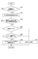
- FIG. 3 is a flowchart showing a first control process which is a basic form. This process is repeatedly executed at a predetermined timing while the driving plan generation ECU 1 and the motion control ECU 2 cooperate to turn on the power key of the vehicle.
- step S1 it is determined whether or not the target trajectory is already present.
- the target trajectory is generated by the driving plan generation ECU 1, travel lane information acquired by white line recognition using image processing from the road image in front acquired by the front camera 10, and the vehicle acquired by the laser radar 11. Obstacle information ahead, current position information of the vehicle acquired by GPS 12, road information to the destination acquired by map DB 13, route information, and a target related to the route set by the driver by input means 14, that is, destination, Based on the request to the destination (travel time priority or fuel economy priority), etc., the route to the destination (which road or intersection to reach the destination) is set, and within that route, A target trajectory is set as a trajectory through which the rear wheel axle center of the host vehicle should pass. In the initial setting, this target trajectory is set as a trajectory passing through the center line of the traveling lane, for example.
- step S2 the process proceeds to step S2 to obtain possible passing area information (step S2).
- This possible passing area information includes the width information of the traveling lane in the front section read from the map DB 13, the measured width information based on the traveling lane information acquired by the front camera 10, the obstacle detected by the laser radar 11, and the speed of the preceding vehicle. , And position information.
- the passable area of the previous road is determined and determined based on the acquired passable area information (step S3).
- This is a range in which the host vehicle can travel safely based on the traveling state of the host vehicle including the width of the traveling lane, the inter-vehicle distance from the preceding vehicle, the presence or absence of surrounding obstacles (for example, the presence or absence of a stopped vehicle), and the vehicle speed. Set the passable area.
- the driving intention of the driver is estimated from the operation state of the driver (step S4).
- this operation state the driver's intention to change the lane, acceleration / deceleration, positioning in the driving lane, etc. is estimated based on the acceleration / deceleration of the vehicle accompanying the accelerator, brake and shift operations, and the steering angle change by the steering operation. To do.
- step S5 based on the estimated will of the driver, the target trajectory / vehicle posture is corrected according to the passable region, and the process is terminated.
- the target trajectory that is comfortable for the driver can be provided. Therefore, if the vehicle behavior control according to the target track is performed, the driver will not feel uncomfortable with the control intervention, and the driver's operation and the control intervention will not conflict with each other. Control can be performed without approaching the limit region that falls.
- FIG. 4 shows a processing flowchart of the second processing mode. Similar to the first control process, this process is also repeatedly executed at a predetermined timing while the driving plan generation ECU 1 and the motion control ECU 2 cooperate to turn on the power key of the vehicle.
- the process proceeds to step S12 to obtain preview information.
- the preview information represents the limit area of the vehicle behavior, and the speed pattern, the acceleration / deceleration pattern, the yaw rate change pattern, and the like are limited in advance based on the conditions of the traveling road, the conditions of the vehicle, and the like. Information.
- step S13 the path curvature of the passage area of the previous passage is calculated in advance.
- This path curvature can be acquired from the traveling lane information of the front section read from the map DB 13 and the traveling lane information acquired by the front camera 10.
- step S14 the passable area of the previous road is determined and determined (step S14). Then, the maximum curvature Rmax and the minimum curvature Rmin in the determined passable area are obtained (step S15).
- a target yaw rate ⁇ * with a fixed target rudder angle ⁇ at the time of planning a target yaw rate ⁇ * 1 corresponding to the obtained maximum curvature Rmax, and a target yaw rate ⁇ * 2 corresponding to the minimum curvature Rmin are obtained, and ⁇ *
- the difference ⁇ 1 between ⁇ * 1 and ⁇ * 1 and the difference ⁇ 2 between ⁇ * and ⁇ * 2 are obtained (step S16).
- an intervention amount ⁇ A is set (step S17).
- This ⁇ A is set by multiplying ⁇ by a predetermined gain k.
- ⁇ is the curvature in the direction in which intervention control is actually performed, among ⁇ 1 and ⁇ 2 obtained in step S16.
- ⁇ 1 is used when controlling to the maximum curvature side from the planning time
- ⁇ 2 is used when controlling to the minimum curvature side from the planning time.
- the gain k is changed based on the driver's will, and is set as shown in FIG. 5 according to the accelerator opening, for example.
- step S18 it is determined whether or not to perform intervention. Specifically, it is determined whether or not the difference between the current yaw rate ⁇ acquired by the yaw rate sensor 23 and the target yaw rate ⁇ * is equal to or greater than the standard threshold A plus the intervention amount ⁇ A. If ⁇ * is less than A + ⁇ A, it is determined that it is not necessary to perform control intervention, and the subsequent processing is skipped and the process ends. On the other hand, if ⁇ * is greater than or equal to A + ⁇ A, it is determined that intervention is necessary, and VSC (Vehicle Stability Control) is activated early. The specific VSC control determines whether the vehicle is oversteered or understeered based on the vehicle attitude.
- VSC Vehicle Stability Control
- VSC intervention control can be performed so that the steer characteristic of the original vehicle is obtained.
- the control in steps S18 and S19 performs passive control intervention, but this control can also be positive control intervention.
- the processing flow shown in FIG. 7 is obtained by changing the processing in steps S18 and S19.
- the intervention determination in step S18a differs from the intervention determination processing in step S18 in that the threshold for intervention determination is different, and the difference between the current yaw rate ⁇ acquired by the yaw rate sensor 23 and the target yaw rate ⁇ * is the standard threshold A. It is determined whether or not the value is equal to or greater than the value obtained by subtracting the intervention amount ⁇ A from
- ⁇ * is less than A ⁇ A, it is determined that it is not necessary to perform control intervention, and the subsequent processing is skipped and the process ends.
- ⁇ * is greater than or equal to A ⁇ A, it is determined that intervention is necessary, and active intervention control by VGRS (Variable Gear Ratio Steering) is performed.
- the VGRS control is performed by changing the actual steering angle with respect to the operation of the steering 31 so as to shift more quickly to the steering angle that realizes the target yaw rate.
- FIG. 7 shows a processing flowchart of the third processing mode.
- the yaw rate deviation ⁇ is a difference between the target yaw rate ⁇ * and the actual yaw rate ⁇ , and when the absolute value is equal to or greater than a predetermined threshold, it is determined that the vehicle is in the vehicle control limit range (vehicle limit range).
- step S22 the passing area route curvature of the previous road is calculated. This passing area path curvature calculation is the same as the processing in step S13 in the second processing mode.
- step S23 the reliability of the route calculation is verified.
- the reliability of the predicted route is determined by comparing the route information acquired by the map DB 13 with the route information acquired by the front camera 10 or the like, and further by comparing the actual travel result.
- the subsequent process is skipped and the process is terminated.
- the process proceeds to step S24.
- step S24 the road width is determined. This is performed by comparing the road width acquired as route information with a predetermined threshold value. This threshold value may be set larger as the vehicle speed is higher and the road curvature is larger. If it is determined that the road width is less than the threshold and is not sufficient, the process proceeds to step S27 described later. If it is determined that the road width is equal to or greater than the threshold, the step is performed. The process proceeds to S25.
- step S25 the driver's intention to accelerate is determined. This may be determined by the presence or absence of an accelerator operation by the driver. If there is no accelerator operation, the process proceeds to step S27 described later, and if there is an accelerator operation, the process proceeds to step S26.
- step S26 since the road width is sufficient and the control according to the driver's acceleration intention can be performed, the VSC intervention timing is delayed more than usual and the control amount is also reduced. As a result, on the road shown in FIG. 8 (boundaries are indicated by 101L and 101R), the original target locus 102 can be corrected to the target locus 103 reflecting the driver's will.
- step S27 If the road width is not sufficient or the driver does not have the intention to accelerate, regular VSC control is performed in step S27. In this case, vehicle behavior control is performed on the road shown in FIG. 8 so that traveling along the original target locus 102 is performed.
- the vehicle behavior control within the control limit range and the control based on the driver's will can be coordinated, and the uncomfortable feeling that the driver feels for the control can be reduced.
- FIG. 9 shows a processing flowchart of the fourth processing mode.
- step S32 determines whether or not VSC control is started. If the VSC control is not being performed, the subsequent processing is skipped and terminated. If the VSC control is being performed, the process proceeds to step S33.
- step S33 the passage area path curvature of the previous road is calculated. This passage area path curvature calculation is the same as the processing in step S13 in the second processing form and step S22 in the third processing form.
- step S34 the reliability of the route calculation is verified. This process is the same as the process of step S23 in the third process form.
- the process proceeds to step S37 described later.
- the process proceeds to step S35.
- step S36 the expected route curvature is compared with the route curvature based on the actual road shape.
- the path curvature based on the actual road shape is a curvature of a path through which the vehicle can pass in an area where the vehicle can actually travel while avoiding an obstacle or the like, and the traveling state of the vehicle (vehicle speed, acceleration, yaw rate). It can change depending on the situation.
- the predicted route curvature is smaller than the route curvature based on the road shape, that is, when the curve of the travelable area is actually steeper than the predicted route curve
- the process proceeds to step S36 and oversteer is performed in the VSC control.
- the control corresponding to the sharp curve is performed by performing the control with the side tendency.
- step S34 when it is determined in step S34 that the reliability of the prefetched route information is low, and when the predicted route curvature is larger than the route curvature based on the road shape, and the actual travelable area curve is actually looser than the predicted route curve. Then, control that tends to be understeer side, which is general control in VSC control, is performed.
- the vehicle behavior control within the control limit range and the control based on the driver's will can be coordinated, and the uncomfortable feeling that the driver feels for the control can be reduced.
- Each ECU may share a part or all of it, or may be shared with other control devices.
Landscapes
- Engineering & Computer Science (AREA)
- Automation & Control Theory (AREA)
- Transportation (AREA)
- Mechanical Engineering (AREA)
- Human Computer Interaction (AREA)
- Control Of Driving Devices And Active Controlling Of Vehicle (AREA)
- Steering Control In Accordance With Driving Conditions (AREA)
- Traffic Control Systems (AREA)
- Navigation (AREA)
Abstract
Description
Claims (7)
- 走行経路設定にあたり、運転者が要求する目標を取得する経路目標取得手段と、
取得した目標に応じて走行経路の選択を行う経路選択手段と、
選択した経路の経路情報を取得する経路情報取得手段と、
選択した経路中における車両の目標軌跡を算出する目標軌跡算出手段と、
前記経路情報に基づいて算出した軌跡の変更可能範囲である可変領域を求める可変領域算出手段と、
を備えている運転支援装置。 Route target acquisition means for acquiring a target requested by the driver in setting the travel route;
Route selection means for selecting a travel route according to the acquired target;
Route information acquisition means for acquiring route information of the selected route;
Target trajectory calculating means for calculating a target trajectory of the vehicle in the selected route;
Variable area calculation means for obtaining a variable area that is a changeable range of the trajectory calculated based on the route information;
A driving assistance device comprising: - 運転者の意志を検出する運転者意志検出手段をさらに備えており、
検出した運転者の意志と求めた可変領域に基づいて運転支援を行う請求項1記載の運転支援装置。 It further comprises a driver will detection means for detecting the driver's will,
The driving support apparatus according to claim 1, wherein driving support is performed based on the detected driver's intention and the obtained variable region. - 運転者の意志を検出する運転者意志検出手段をさらに備えており、
検出した運転者の意志と求めた可変領域に基づいて算出した目標軌跡の修正を行う請求項1記載の運転支援装置。 It further comprises a driver will detection means for detecting the driver's will,
The driving support apparatus according to claim 1, wherein the target locus calculated based on the detected driver's intention and the obtained variable region is corrected. - 前記目標軌跡の修正は、軌跡中の曲率を変更するものである請求項3記載の運転支援装置。 The driving support device according to claim 3, wherein the correction of the target locus changes a curvature in the locus.
- 車両の挙動を制御する車両挙動制御手段をさらに備えており、
検出した運転者の意志と求めた可変領域に基づいて前記車両挙動制御手段による制御介入割合を変更する請求項2記載の運転支援装置。 Vehicle behavior control means for controlling the behavior of the vehicle,
The driving support device according to claim 2, wherein a control intervention ratio by the vehicle behavior control means is changed based on the detected driver's intention and the obtained variable region. - 前記車両挙動制御手段は、操舵特性を変更する操舵特性変更手段である請求項5記載の運転支援装置。 The driving support apparatus according to claim 5, wherein the vehicle behavior control means is steering characteristic changing means for changing a steering characteristic.
- 車両の挙動を制御する車両挙動制御手段と、
検出した運転者の意志に基づいて、走行経路の予想曲率を求める予想曲率算出手段と、
求めた予想曲率と、前記経路情報取得手段により取得した当該経路の曲率とを比較する曲率比較手段をさらに備えており、
当該比較結果に基づいて前記車両挙動制御手段による制御状態を変更する請求項1記載の運転支援装置 Vehicle behavior control means for controlling the behavior of the vehicle;
An expected curvature calculating means for obtaining an expected curvature of the travel route based on the detected driver's intention;
A curvature comparison unit that compares the calculated expected curvature with the curvature of the route acquired by the route information acquisition unit;
The driving support device according to claim 1, wherein the control state by the vehicle behavior control means is changed based on the comparison result.
Priority Applications (5)
| Application Number | Priority Date | Filing Date | Title |
|---|---|---|---|
| US13/376,601 US20120277955A1 (en) | 2009-12-28 | 2009-12-28 | Driving assistance device |
| DE112009005485T DE112009005485T5 (en) | 2009-12-28 | 2009-12-28 | Driving support device |
| CN200980161693.XA CN102548822B (en) | 2009-12-28 | 2009-12-28 | Driving assistance device |
| PCT/JP2009/071781 WO2011080830A1 (en) | 2009-12-28 | 2009-12-28 | Driving assistance device |
| JP2011547213A JP5168421B2 (en) | 2009-12-28 | 2009-12-28 | Driving assistance device |
Applications Claiming Priority (1)
| Application Number | Priority Date | Filing Date | Title |
|---|---|---|---|
| PCT/JP2009/071781 WO2011080830A1 (en) | 2009-12-28 | 2009-12-28 | Driving assistance device |
Publications (1)
| Publication Number | Publication Date |
|---|---|
| WO2011080830A1 true WO2011080830A1 (en) | 2011-07-07 |
Family
ID=44226265
Family Applications (1)
| Application Number | Title | Priority Date | Filing Date |
|---|---|---|---|
| PCT/JP2009/071781 WO2011080830A1 (en) | 2009-12-28 | 2009-12-28 | Driving assistance device |
Country Status (5)
| Country | Link |
|---|---|
| US (1) | US20120277955A1 (en) |
| JP (1) | JP5168421B2 (en) |
| CN (1) | CN102548822B (en) |
| DE (1) | DE112009005485T5 (en) |
| WO (1) | WO2011080830A1 (en) |
Cited By (1)
| Publication number | Priority date | Publication date | Assignee | Title |
|---|---|---|---|---|
| WO2014091566A1 (en) * | 2012-12-11 | 2014-06-19 | トヨタ自動車株式会社 | Drive assistance device and drive assistance method |
Families Citing this family (16)
| Publication number | Priority date | Publication date | Assignee | Title |
|---|---|---|---|---|
| JP5163705B2 (en) * | 2010-07-07 | 2013-03-13 | 株式会社デンソー | Vehicle entry / exit history association device and program for vehicle entry / exit history association device |
| EP2919217B1 (en) * | 2012-11-08 | 2017-09-06 | Toyota Jidosha Kabushiki Kaisha | Driving assistance device and driving assistance method |
| US9031729B2 (en) * | 2012-11-29 | 2015-05-12 | Volkswagen Ag | Method and system for controlling a vehicle |
| DE102014200687A1 (en) * | 2014-01-16 | 2015-07-16 | Robert Bosch Gmbh | Method for operating a vehicle |
| KR101567207B1 (en) * | 2014-04-16 | 2015-11-13 | 현대자동차주식회사 | Vehicle control system and mehtod for self-control driving thereof |
| KR101551092B1 (en) * | 2014-05-15 | 2015-09-07 | 현대자동차주식회사 | Apparatus for controlling speed of vehicle using image and method thereof |
| JP6598019B2 (en) * | 2015-04-21 | 2019-10-30 | パナソニックIpマネジメント株式会社 | Driving support method, driving support device, driving control device, vehicle, and driving support program using the same |
| JP6303217B2 (en) * | 2015-10-28 | 2018-04-04 | 本田技研工業株式会社 | Vehicle control device, vehicle control method, and vehicle control program |
| US10303166B2 (en) * | 2016-05-23 | 2019-05-28 | nuTonomy Inc. | Supervisory control of vehicles |
| TWI604980B (en) * | 2016-11-24 | 2017-11-11 | 國立臺北科技大學 | Vehicle control system and vehicle control method |
| DE102017205508A1 (en) * | 2017-03-31 | 2018-10-04 | Robert Bosch Gmbh | Method for automatic movement control of a vehicle |
| JP6969962B2 (en) * | 2017-10-05 | 2021-11-24 | トヨタ自動車株式会社 | Map information providing system for vehicle driving support and / or driving control |
| US20190132555A1 (en) * | 2017-10-30 | 2019-05-02 | Qualcomm Incorporated | Methods and systems to broadcast sensor outputs in an automotive environment |
| JP7159562B2 (en) | 2018-01-29 | 2022-10-25 | 株式会社デンソー | Vehicle control system |
| JP7251294B2 (en) * | 2019-04-25 | 2023-04-04 | 株式会社アドヴィックス | Vehicle travel control device |
| JP7156238B2 (en) * | 2019-10-15 | 2022-10-19 | トヨタ自動車株式会社 | vehicle control system |
Citations (4)
| Publication number | Priority date | Publication date | Assignee | Title |
|---|---|---|---|---|
| JPH11328596A (en) * | 1998-05-13 | 1999-11-30 | Toyota Motor Corp | Drive assisting device |
| JP2008180591A (en) * | 2007-01-24 | 2008-08-07 | Toyota Motor Corp | Travel control plan generation system |
| JP2009115464A (en) * | 2007-11-01 | 2009-05-28 | Toyota Motor Corp | Method and system for forming drive trace |
| JP2009208602A (en) * | 2008-03-04 | 2009-09-17 | Nissan Motor Co Ltd | Supporting apparatus and method for lane keeping |
Family Cites Families (28)
| Publication number | Priority date | Publication date | Assignee | Title |
|---|---|---|---|---|
| JP3183966B2 (en) * | 1992-04-20 | 2001-07-09 | マツダ株式会社 | Vehicle travel control device |
| DE4408745C2 (en) * | 1993-03-26 | 1997-02-27 | Honda Motor Co Ltd | Driving control device for vehicles |
| US5661650A (en) * | 1994-02-23 | 1997-08-26 | Honda Giken Kogyo Kabushiki Kaisha | System for controlling a vehicle relative to a judged shape of a travel road |
| JPH1031799A (en) * | 1996-07-15 | 1998-02-03 | Toyota Motor Corp | Automatic traveling controller |
| US6185492B1 (en) * | 1997-07-09 | 2001-02-06 | Toyota Jidosha Kabushiki Kaisha | Vehicle steering control apparatus for assisting a steering effort to move a vehicle along a line desired by a driver |
| JPH11144185A (en) * | 1997-09-03 | 1999-05-28 | Honda Motor Co Ltd | Automatic drive control guidance system |
| WO1999030919A1 (en) * | 1997-12-15 | 1999-06-24 | Volkswagen Aktiengesellschaft | Method for regulating speed and distance during passing maneuvers |
| DE19954536B4 (en) * | 1999-11-12 | 2010-09-23 | Robert Bosch Gmbh | Method for evaluating objects in the course of a vehicle |
| US6502035B2 (en) * | 2000-08-02 | 2002-12-31 | Alfred B. Levine | Automotive safety enhansing system |
| JP2004508627A (en) * | 2000-09-08 | 2004-03-18 | レイセオン・カンパニー | Route prediction system and method |
| US7565230B2 (en) * | 2000-10-14 | 2009-07-21 | Temic Automotive Of North America, Inc. | Method and apparatus for improving vehicle operator performance |
| NL1019191C2 (en) * | 2001-10-18 | 2003-04-23 | Frog Navigation Systems B V | Vehicle and method of driving thereof. |
| US7124027B1 (en) * | 2002-07-11 | 2006-10-17 | Yazaki North America, Inc. | Vehicular collision avoidance system |
| JP4647201B2 (en) * | 2003-12-05 | 2011-03-09 | 富士重工業株式会社 | Vehicle travel control device |
| US20060095171A1 (en) * | 2004-11-02 | 2006-05-04 | Whittaker William L | Methods, devices and systems for high-speed autonomous vehicle and high-speed autonomous vehicle |
| EP1659367B1 (en) * | 2004-11-19 | 2008-09-03 | Harman Becker Automotive Systems GmbH | Vehicle navigation with integrated curve warning using clothoid models |
| US7400963B2 (en) * | 2005-12-09 | 2008-07-15 | Gm Global Technology Operations, Inc. | Speed control method for vehicle approaching and traveling on a curve |
| JP4743275B2 (en) * | 2006-03-01 | 2011-08-10 | トヨタ自動車株式会社 | Own vehicle route determination method and own vehicle route determination device |
| JP4759547B2 (en) * | 2007-09-27 | 2011-08-31 | 日立オートモティブシステムズ株式会社 | Driving support device |
| US8224525B1 (en) * | 2008-02-29 | 2012-07-17 | Javad Gnss, Inc. | Indication of attraction domains for controlled planar motion of a ground vehicle |
| US8170739B2 (en) * | 2008-06-20 | 2012-05-01 | GM Global Technology Operations LLC | Path generation algorithm for automated lane centering and lane changing control system |
| US8417415B2 (en) * | 2008-07-02 | 2013-04-09 | Michael Phelan | Driver authentication system and method for monitoring and controlling vehicle usage |
| US8126642B2 (en) * | 2008-10-24 | 2012-02-28 | Gray & Company, Inc. | Control and systems for autonomously driven vehicles |
| DE102009037965A1 (en) * | 2009-08-18 | 2011-02-24 | Dr. Ing. H.C. F. Porsche Aktiengesellschaft | Method and device for outputting information to the driver of a vehicle |
| US8886365B2 (en) * | 2009-10-30 | 2014-11-11 | Ford Global Technologies, Llc | Vehicle and method for advising driver of same |
| US8258934B2 (en) * | 2009-10-30 | 2012-09-04 | Ford Global Technologies, Llc | Vehicle and method of advising a driver therein |
| US9108598B2 (en) * | 2011-01-13 | 2015-08-18 | Continental Automotive Systems, Inc. | System and method for maneuvering a vehicle-trailer unit in reverse travel |
| US20130268156A1 (en) * | 2012-04-07 | 2013-10-10 | Robert Wilhelm Schumann | Data Privacy Mechanism |
-
2009
- 2009-12-28 CN CN200980161693.XA patent/CN102548822B/en not_active Expired - Fee Related
- 2009-12-28 WO PCT/JP2009/071781 patent/WO2011080830A1/en active Application Filing
- 2009-12-28 JP JP2011547213A patent/JP5168421B2/en active Active
- 2009-12-28 US US13/376,601 patent/US20120277955A1/en not_active Abandoned
- 2009-12-28 DE DE112009005485T patent/DE112009005485T5/en not_active Withdrawn
Patent Citations (4)
| Publication number | Priority date | Publication date | Assignee | Title |
|---|---|---|---|---|
| JPH11328596A (en) * | 1998-05-13 | 1999-11-30 | Toyota Motor Corp | Drive assisting device |
| JP2008180591A (en) * | 2007-01-24 | 2008-08-07 | Toyota Motor Corp | Travel control plan generation system |
| JP2009115464A (en) * | 2007-11-01 | 2009-05-28 | Toyota Motor Corp | Method and system for forming drive trace |
| JP2009208602A (en) * | 2008-03-04 | 2009-09-17 | Nissan Motor Co Ltd | Supporting apparatus and method for lane keeping |
Cited By (3)
| Publication number | Priority date | Publication date | Assignee | Title |
|---|---|---|---|---|
| WO2014091566A1 (en) * | 2012-12-11 | 2014-06-19 | トヨタ自動車株式会社 | Drive assistance device and drive assistance method |
| US20150329108A1 (en) * | 2012-12-11 | 2015-11-19 | Toyota Jidosha Kabushiki Kaisha | Driving assistance device and driving assistance method |
| JP5949943B2 (en) * | 2012-12-11 | 2016-07-13 | トヨタ自動車株式会社 | Driving support device and driving support method |
Also Published As
| Publication number | Publication date |
|---|---|
| JP5168421B2 (en) | 2013-03-21 |
| JPWO2011080830A1 (en) | 2013-05-09 |
| US20120277955A1 (en) | 2012-11-01 |
| CN102548822B (en) | 2015-06-03 |
| DE112009005485T5 (en) | 2012-10-18 |
| CN102548822A (en) | 2012-07-04 |
Similar Documents
| Publication | Publication Date | Title |
|---|---|---|
| JP5168421B2 (en) | Driving assistance device | |
| US11008039B2 (en) | Lane change assist apparatus for vehicle | |
| US9669813B2 (en) | Vehicle driving support control device | |
| JP4865727B2 (en) | Method for maneuvering vehicle in parking area and parking assist device | |
| JP6055525B1 (en) | Vehicle travel control device | |
| JP6432679B2 (en) | Stop position setting apparatus and method | |
| JP4995029B2 (en) | Vehicle driving support device | |
| US9031709B2 (en) | Vehicle travel control apparatus and vehicle travel control method | |
| JP6952014B2 (en) | Vehicle control device, vehicle control method, and vehicle control system | |
| JP7487994B2 (en) | Vehicle driving assistance device. | |
| JP7051611B2 (en) | Vehicle control unit | |
| JP2009012672A (en) | Traveling controller for vehicle | |
| KR20230009949A (en) | Path control module, associated path control device and associated method | |
| JP2012144160A (en) | Driving support device | |
| JP2011088574A (en) | Vehicle controller | |
| US10955849B2 (en) | Automatic driving system | |
| JP6670140B2 (en) | Vehicle control device and vehicle control method | |
| JP7263827B2 (en) | VEHICLE DRIVING ASSIST METHOD AND DRIVING ASSIST DEVICE | |
| JP4970134B2 (en) | Vehicle driving support device | |
| JP2004196100A (en) | Steering control device for vehicle | |
| JP7275646B2 (en) | VEHICLE TRIP CONTROL METHOD AND TRIP CONTROL DEVICE | |
| JP2010155527A (en) | Vehicle for changing mode of driving assist based on preview information | |
| JP6496588B2 (en) | Vehicle behavior control device | |
| JP2020132009A (en) | Travel control method and travel control device for vehicle | |
| JP7218608B2 (en) | VEHICLE TRIP CONTROL METHOD AND TRIP CONTROL DEVICE |
Legal Events
| Date | Code | Title | Description |
|---|---|---|---|
| WWE | Wipo information: entry into national phase |
Ref document number: 200980161693.X Country of ref document: CN |
|
| 121 | Ep: the epo has been informed by wipo that ep was designated in this application |
Ref document number: 09852808 Country of ref document: EP Kind code of ref document: A1 |
|
| WWE | Wipo information: entry into national phase |
Ref document number: 2011547213 Country of ref document: JP |
|
| WWE | Wipo information: entry into national phase |
Ref document number: 13376601 Country of ref document: US |
|
| WWE | Wipo information: entry into national phase |
Ref document number: 1120090054854 Country of ref document: DE Ref document number: 112009005485 Country of ref document: DE |
|
| 122 | Ep: pct application non-entry in european phase |
Ref document number: 09852808 Country of ref document: EP Kind code of ref document: A1 |