WO2011037068A1 - Space-securing device - Google Patents
Space-securing device Download PDFInfo
- Publication number
- WO2011037068A1 WO2011037068A1 PCT/JP2010/066061 JP2010066061W WO2011037068A1 WO 2011037068 A1 WO2011037068 A1 WO 2011037068A1 JP 2010066061 W JP2010066061 W JP 2010066061W WO 2011037068 A1 WO2011037068 A1 WO 2011037068A1
- Authority
- WO
- WIPO (PCT)
- Prior art keywords
- heart
- space
- securing device
- pericardial
- space securing
- Prior art date
Links
Images


Classifications
-
- A—HUMAN NECESSITIES
- A61—MEDICAL OR VETERINARY SCIENCE; HYGIENE
- A61B—DIAGNOSIS; SURGERY; IDENTIFICATION
- A61B17/00—Surgical instruments, devices or methods, e.g. tourniquets
- A61B17/34—Trocars; Puncturing needles
- A61B17/3417—Details of tips or shafts, e.g. grooves, expandable, bendable; Multiple coaxial sliding cannulas, e.g. for dilating
- A61B17/3421—Cannulas
- A61B17/3431—Cannulas being collapsible, e.g. made of thin flexible material
-
- A—HUMAN NECESSITIES
- A61—MEDICAL OR VETERINARY SCIENCE; HYGIENE
- A61B—DIAGNOSIS; SURGERY; IDENTIFICATION
- A61B17/00—Surgical instruments, devices or methods, e.g. tourniquets
- A61B17/02—Surgical instruments, devices or methods, e.g. tourniquets for holding wounds open; Tractors
- A61B17/0218—Surgical instruments, devices or methods, e.g. tourniquets for holding wounds open; Tractors for minimally invasive surgery
-
- A—HUMAN NECESSITIES
- A61—MEDICAL OR VETERINARY SCIENCE; HYGIENE
- A61B—DIAGNOSIS; SURGERY; IDENTIFICATION
- A61B17/00—Surgical instruments, devices or methods, e.g. tourniquets
- A61B17/34—Trocars; Puncturing needles
- A61B17/3478—Endoscopic needles, e.g. for infusion
-
- A—HUMAN NECESSITIES
- A61—MEDICAL OR VETERINARY SCIENCE; HYGIENE
- A61B—DIAGNOSIS; SURGERY; IDENTIFICATION
- A61B90/00—Instruments, implements or accessories specially adapted for surgery or diagnosis and not covered by any of the groups A61B1/00 - A61B50/00, e.g. for luxation treatment or for protecting wound edges
- A61B90/30—Devices for illuminating a surgical field, the devices having an interrelation with other surgical devices or with a surgical procedure
-
- A—HUMAN NECESSITIES
- A61—MEDICAL OR VETERINARY SCIENCE; HYGIENE
- A61M—DEVICES FOR INTRODUCING MEDIA INTO, OR ONTO, THE BODY; DEVICES FOR TRANSDUCING BODY MEDIA OR FOR TAKING MEDIA FROM THE BODY; DEVICES FOR PRODUCING OR ENDING SLEEP OR STUPOR
- A61M25/00—Catheters; Hollow probes
- A61M25/10—Balloon catheters
- A61M25/1011—Multiple balloon catheters
-
- A—HUMAN NECESSITIES
- A61—MEDICAL OR VETERINARY SCIENCE; HYGIENE
- A61B—DIAGNOSIS; SURGERY; IDENTIFICATION
- A61B17/00—Surgical instruments, devices or methods, e.g. tourniquets
- A61B17/00234—Surgical instruments, devices or methods, e.g. tourniquets for minimally invasive surgery
- A61B2017/00238—Type of minimally invasive operation
- A61B2017/00243—Type of minimally invasive operation cardiac
- A61B2017/00247—Making holes in the wall of the heart, e.g. laser Myocardial revascularization
-
- A—HUMAN NECESSITIES
- A61—MEDICAL OR VETERINARY SCIENCE; HYGIENE
- A61B—DIAGNOSIS; SURGERY; IDENTIFICATION
- A61B17/00—Surgical instruments, devices or methods, e.g. tourniquets
- A61B2017/00831—Material properties
- A61B2017/00876—Material properties magnetic
-
- A—HUMAN NECESSITIES
- A61—MEDICAL OR VETERINARY SCIENCE; HYGIENE
- A61B—DIAGNOSIS; SURGERY; IDENTIFICATION
- A61B17/00—Surgical instruments, devices or methods, e.g. tourniquets
- A61B17/02—Surgical instruments, devices or methods, e.g. tourniquets for holding wounds open; Tractors
- A61B2017/0237—Surgical instruments, devices or methods, e.g. tourniquets for holding wounds open; Tractors for heart surgery
-
- A—HUMAN NECESSITIES
- A61—MEDICAL OR VETERINARY SCIENCE; HYGIENE
- A61B—DIAGNOSIS; SURGERY; IDENTIFICATION
- A61B17/00—Surgical instruments, devices or methods, e.g. tourniquets
- A61B17/30—Surgical pincettes without pivotal connections
- A61B2017/306—Surgical pincettes without pivotal connections holding by means of suction
- A61B2017/308—Surgical pincettes without pivotal connections holding by means of suction with suction cups
-
- A—HUMAN NECESSITIES
- A61—MEDICAL OR VETERINARY SCIENCE; HYGIENE
- A61B—DIAGNOSIS; SURGERY; IDENTIFICATION
- A61B17/00—Surgical instruments, devices or methods, e.g. tourniquets
- A61B17/34—Trocars; Puncturing needles
- A61B17/3417—Details of tips or shafts, e.g. grooves, expandable, bendable; Multiple coaxial sliding cannulas, e.g. for dilating
- A61B17/3421—Cannulas
- A61B2017/3445—Cannulas used as instrument channel for multiple instruments
- A61B2017/3449—Cannulas used as instrument channel for multiple instruments whereby the instrument channels merge into one single channel
-
- A—HUMAN NECESSITIES
- A61—MEDICAL OR VETERINARY SCIENCE; HYGIENE
- A61B—DIAGNOSIS; SURGERY; IDENTIFICATION
- A61B18/00—Surgical instruments, devices or methods for transferring non-mechanical forms of energy to or from the body
- A61B2018/00315—Surgical instruments, devices or methods for transferring non-mechanical forms of energy to or from the body for treatment of particular body parts
- A61B2018/00345—Vascular system
- A61B2018/00351—Heart
- A61B2018/00392—Transmyocardial revascularisation
-
- A—HUMAN NECESSITIES
- A61—MEDICAL OR VETERINARY SCIENCE; HYGIENE
- A61B—DIAGNOSIS; SURGERY; IDENTIFICATION
- A61B90/00—Instruments, implements or accessories specially adapted for surgery or diagnosis and not covered by any of the groups A61B1/00 - A61B50/00, e.g. for luxation treatment or for protecting wound edges
- A61B90/36—Image-producing devices or illumination devices not otherwise provided for
- A61B90/361—Image-producing devices, e.g. surgical cameras
- A61B2090/3618—Image-producing devices, e.g. surgical cameras with a mirror
-
- A—HUMAN NECESSITIES
- A61—MEDICAL OR VETERINARY SCIENCE; HYGIENE
- A61B—DIAGNOSIS; SURGERY; IDENTIFICATION
- A61B90/00—Instruments, implements or accessories specially adapted for surgery or diagnosis and not covered by any of the groups A61B1/00 - A61B50/00, e.g. for luxation treatment or for protecting wound edges
- A61B90/36—Image-producing devices or illumination devices not otherwise provided for
- A61B90/361—Image-producing devices, e.g. surgical cameras
-
- A—HUMAN NECESSITIES
- A61—MEDICAL OR VETERINARY SCIENCE; HYGIENE
- A61M—DEVICES FOR INTRODUCING MEDIA INTO, OR ONTO, THE BODY; DEVICES FOR TRANSDUCING BODY MEDIA OR FOR TAKING MEDIA FROM THE BODY; DEVICES FOR PRODUCING OR ENDING SLEEP OR STUPOR
- A61M25/00—Catheters; Hollow probes
- A61M25/10—Balloon catheters
- A61M2025/1043—Balloon catheters with special features or adapted for special applications
- A61M2025/1047—Balloon catheters with special features or adapted for special applications having centering means, e.g. balloons having an appropriate shape
-
- A—HUMAN NECESSITIES
- A61—MEDICAL OR VETERINARY SCIENCE; HYGIENE
- A61M—DEVICES FOR INTRODUCING MEDIA INTO, OR ONTO, THE BODY; DEVICES FOR TRANSDUCING BODY MEDIA OR FOR TAKING MEDIA FROM THE BODY; DEVICES FOR PRODUCING OR ENDING SLEEP OR STUPOR
- A61M25/00—Catheters; Hollow probes
- A61M25/10—Balloon catheters
- A61M2025/1043—Balloon catheters with special features or adapted for special applications
- A61M2025/1052—Balloon catheters with special features or adapted for special applications for temporarily occluding a vessel for isolating a sector
-
- A—HUMAN NECESSITIES
- A61—MEDICAL OR VETERINARY SCIENCE; HYGIENE
- A61M—DEVICES FOR INTRODUCING MEDIA INTO, OR ONTO, THE BODY; DEVICES FOR TRANSDUCING BODY MEDIA OR FOR TAKING MEDIA FROM THE BODY; DEVICES FOR PRODUCING OR ENDING SLEEP OR STUPOR
- A61M25/00—Catheters; Hollow probes
- A61M25/01—Introducing, guiding, advancing, emplacing or holding catheters
- A61M25/02—Holding devices, e.g. on the body
- A61M25/04—Holding devices, e.g. on the body in the body, e.g. expansible
Definitions
- the present invention relates to a space securing device.
- an endoscope and treatment tool are inserted into the pericardial space directly under the xiphoid process, and stem cells are injected into the diseased part (for example, the boundary region between the myocardial infarction part and the normal part) without performing thoracotomy.
- a pericardial endoscopic technique is known (for example, see Patent Document 1).
- the pericardial endoscopic technique disclosed in Patent Document 1 has a disadvantage in that the force inserted from the pericardium to the heart always acts on the endoscope inserted into the pericardial cavity. That is, in order to observe and treat the heart with an endoscope inserted into the pericardial cavity, it is necessary to form a space between the outer wall surface of the heart and the endoscope.
- the pericardial endoscopic technique of Patent Document 1 has a disadvantage that the operation from the pericardium acting on the endoscope is not free and the operability is poor.
- the present invention has been made in view of the above-described circumstances, and in pericardial endoscopic procedures, the pericardial cavity is unnecessarily expanded without providing special space securing means in the endoscope or treatment instrument.
- a space securing device capable of improving the operability while securing a space necessary for operation of an endoscope and a treatment instrument without suppressing complications such as cardiac tamponade, for example. It is aimed.
- the present invention provides the following means.
- the present invention relates to a pericardial pressing part that presses the pericardium from the pericardial cavity side, a cardiac pressing part that presses the heart surface from the pericardial cavity side, and a connecting part that connects the pericardial pressing part and the cardiac pressing part.
- a space is formed between the pericardial pressing portion and the heart pressing portion by generating a resilient force that can be expanded against the pressure received from the pericardium and the heart.
- the pericardial pressing portion and the heart pressing portion are pushed and expanded in a direction away from each other by the elastic force of the connecting portion.
- the pericardium is moved away from the heart surface, and a space is formed between the pericardial pressing part and the cardiac pressing part.
- the endoscope and the treatment tool can be operated without being performed.
- the said pericardial press part is formed in plate shape, and the reflective surface which reflects illumination light is provided in the surface on the opposite side to the side which contacts the said pericardium of this pericardial press part. Also good.
- the illumination light from the distal end of the endoscope that has entered the space is directed toward the pericardial pressing part.
- the illumination light is reflected by the reflecting surface provided in the pericardial pressing part, and is irradiated on the surface of the heart facing the reflecting surface.
- the distance from the emission end of the illumination light to the heart surface can be secured, and it is possible to illuminate a wide range of the heart surface without using excessive diffused light.
- the pericardial pressing portion is provided with a pericardial opening that opens the space toward the pericardium, and the cardiac pressing portion opens the space toward the heart.
- the connecting portion may be formed in an annular shape that gradually spreads from the pericardial pressing portion toward the cardiac pressing portion.
- the pericardial pressing part is brought into contact with the pericardium
- the cardiac pressing part is brought into contact with the heart
- the pericardium and the heart are in contact with each other. It expands to increase the distance and forms a space inside.
- This space is opened to the pericardium side by the pericardial side opening and opened to the heart side by the heart side opening.
- An endoscope inserted into the pericardial cavity can be easily run along the outer surface of the connecting portion by the connecting portion formed in an annular shape gradually spreading from the pericardial pressing portion toward the heart pressing portion.
- Or the like can easily enter the space from between the pericardial pressing portion and the pericardium through the pericardial opening.
- the tip of an endoscope or the like can be placed at a position away from the heart surface to observe the heart surface.
- the connecting portion may have an outer surface formed of an outwardly convex curved surface at least in the vicinity of the pericardial pressing portion.
- the connecting portion may have an outer surface formed of a concave curved surface on the outer side at least in the vicinity of the heart pressing portion.
- the inclination angle can be gradually increased from the heart surface to the outer surface of the connecting portion, and the connecting portion such as an endoscope introduced along the surface of the heart in the pericardial cavity. The ease of getting on the outer surface can be improved.
- the outer surface may be provided with one or more grooves extending from the outer edge of the heart pressing portion to the inner edge of the pericardial opening.
- the said heart press part may be formed in the substantially U shape surrounding a part of said space, and the opening part which connects the inside and outside of the said space may be provided in the said connection part.
- the space securing device can be arranged so as to surround the treatment range of the heart surface by the substantially U-shaped heart pressing portion, and an endoscope or the like can be provided via the opening provided in the connecting portion. It is possible to operate the endoscope or the like without being obstructed by the heart, pericardium, or the like.
- an opening for connecting the connecting portion and the inside and outside of the space may be provided, and at least a part of the heart pressing portion may include an inclined surface that increases from the outside to the inside of the opening. Good. By doing so, the tip portion can be lifted from the surface of the heart by the inclined surface when the endoscope or the like enters the space, and observation and treatment can be performed at a position away from the surface of the heart. .
- suck the said heart press part on the surface of the said heart may be sufficient.
- the space securing device can be adsorbed to the heart surface by the adsorbing means and can be stably fixed, and even if the endoscope collides with the space securing device during the operation of the endoscope, It is possible to prevent an inconvenience that the securing device moves from a desired position.
- the suction means may cause the heart pressing portion to be sucked onto the surface of the heart by negative pressure.
- the attracting means may include a magnet provided in one of the heart and the heart pressing portion, and a magnet or a magnetic material provided in the other. In this way, the space securing device can be easily and stably adsorbed to the heart surface.
- the said invention may deform
- a guide tube sheath or endoscope, etc.
- the space securing device housed in the guide tube in a contracted state is pushed out of the guide tube
- the guide The space securing device released from the tube expands in the pericardial space in an attempt to restore its expanded state by its elastic force, and widens the gap between the heart and the pericardium to form a space inside.
- the space is open to the heart surface and is accessible from the outside. Therefore, the operation of the endoscope and the treatment tool is prevented from being obstructed by the pericardium and the heart by allowing the distal end of the endoscope and the treatment tool to enter from the outside into the formed space. Can be improved.
- the endoscope and the treatment tool are provided without providing a special space securing means in the endoscope and the treatment tool and without unnecessarily expanding the pericardial cavity.
- FIG. 1 It is a perspective view which shows the other modification of the space ensuring device of FIG. It is a longitudinal cross-sectional view which shows the use condition in the pericardial cavity of the space securing device of FIG. It is a perspective view which shows the other modification of the space ensuring device of FIG. It is a longitudinal cross-sectional view which shows the use condition in the pericardial cavity of the space securing device of FIG. It is a perspective view which shows the other modification of the space ensuring device of FIG. It is a perspective view which shows the other modification of the space securing device similar to FIG. It is a perspective view which shows the other modification of the space ensuring device of FIG. It is a perspective view which shows the other modification of the space ensuring device of FIG.
- FIG. It is a perspective view which shows the modification of the space ensuring device of FIG. It is a perspective view which shows the modification of the space ensuring device of FIG. It is a perspective view which shows the other modification of the space ensuring device of FIG. It is a perspective view which shows the other modification of the space ensuring device of FIG. It is a perspective view which shows the other modification of the space ensuring device of FIG. It is a longitudinal cross-sectional view which shows the use condition in the pericardial cavity of the space securing device of FIG. It is a perspective view which shows the modification of the space ensuring device of FIG. It is a top view which shows the modification of the space ensuring device of FIG. It is a top view explaining the collection
- FIG. 7 is a perspective view showing another modified example of the space securing device of FIG. 5 in an expanded state.
- FIG. 26 is a perspective view showing a contracted state of the space securing device of FIG. 25.
- FIG. 26 is a perspective view showing a modified example of the space securing device of FIG. 25 and showing an expanded state. It is a top view which shows the contraction state of the space ensuring device of FIG. It is a perspective view which is a modification of the space securing device of FIG. 25 and shows a contracted state. It is a perspective view which shows the expansion state of the space securing device of FIG. It is a bottom view which shows the modification of the space securing device of FIG. It is a longitudinal cross-sectional view which shows the use condition in the pericardial cavity of the modification of the space ensuring device of FIG.
- a space securing device 1 according to a first embodiment of the present invention will be described below with reference to the drawings.
- the space securing device 1 according to the present embodiment is disposed in a pericardial cavity C that is disposed between the heart A and the pericardium B.
- a device that widens the spacing is disposed in a pericardial cavity C that is disposed between the heart A and the pericardium B.
- the space securing device 1 is made of an elastic material that can be expanded and contracted, such as silicone resin.
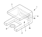
- the space securing device 1 is an integral member including a heart pressing portion 2 that contacts the surface of the heart A, a pericardial pressing portion 3 that contacts the inner surface of the pericardium B, and a connecting portion 4 that connects them.
- the heart pressing portion 2 is a substantially U-shaped flat plate portion.
- the heart pressing unit 2 is disposed at a position that partially surrounds the periphery of the range (for example, diseased site D) to be treated by the treatment tool 6 while being observed with the endoscope 5.
- the pericardial pressing part 3 is, for example, a rectangular flat plate part as shown in FIG. As shown in FIG. 1, the pericardial pressing unit 3 presses the pericardium B with the outer surface. As shown in FIG. 1, the surface opposite to the outer surface of the pericardial pressing portion 3 is coated with a reflective film 3a so that the light L can be reflected.
- the connecting part 4 is a part that connects the one end of the heart pressing part 2 and the pericardial pressing part 3.
- the connecting portion 4 includes a through hole 4a into which the endoscope 5 can be inserted, and a through hole 4b into which the treatment tool 6 can be inserted.
- the through-hole 4a for the endoscope 5 extends from the outside of the space securing device 1 into the space 7 formed between the heart pressing part 2 and the pericardial pressing part 3 in a direction away from the heart pressing part 2. Inclined. Thereby, the front end surface 5a of the endoscope 5 inserted from the outside can be easily arranged obliquely upward.
- the through-hole 4b for the treatment instrument 6 may be inclined in a direction away from the pericardial pressing portion 3 from the outside of the space securing device 1 into the space 7.
- the space securing device 1 includes, for example, a contracted state that can be accommodated in a sheath (guide tube) 8 inserted into the pericardial cavity C from the lower part of the xiphoid process, As shown in FIG. 3, the push rod 9 inserted into the sheath 8 from the proximal end side can be expanded and contracted between the expanded state released by being pushed out of the sheath 8. In the expanded state, the space securing device 1 is expanded by a preset elasticity. Therefore, the space securing device 1 forms a sufficient space 7 without unnecessarily expanding the interval between the pericardium B and the heart A.
- the space securing device 1 configured as described above will be described below.
- a diseased part D of the heart A for example, a boundary region between a myocardial infarction part and a normal part
- the distal end portion of the sheath 8 accommodated in a state where the space securing device 1 is contracted in the vicinity is inserted into the pericardial cavity C as shown in FIG. In this state, the region where the pericardium B and the heart A are separated is limited to the vicinity of the distal end portion of the sheath 8.
- the space securing device 1 accommodated in the sheath 8 is pushed out of the sheath 8 by the push rod 9 introduced from the proximal end side of the sheath 8 as shown in FIG.
- the heart pressing part 2 is arranged at a position surrounding the disease site D as shown in FIG. Since the space securing device 1 is made of an elastic material, it is expanded by its elastic force.
- the pericardium B is pressed by the pericardial pressing unit 3 and the heart A is pressed by the cardiac pressing unit 2, so that the interval between the pericardial B and the heart A can be enlarged in the vicinity of the diseased site D.
- the space securing device 1 is expanded by a preset elasticity in the expanded state. Therefore, a sufficient space 7 can be formed without unnecessarily expanding the interval between the pericardium B and the heart A.
- the endoscope 5 and the treatment tool 6 are guided into the pericardial cavity C through the sheath 8.
- the endoscope 5 is inserted from the heart A side through-hole 4 a provided in the connecting portion 4, the treatment tool 6 is inserted from the pericardium B-side through hole 4 b, and the heart pressing unit 2 and the pericardial pressing unit 3. It inserts in the space 7 formed between.
- the through hole 4a for the endoscope 5 is inclined in a direction away from the heart pressing portion 2 toward the space 7. Therefore, the endoscope 5 inserted into the through hole 4a is easily guided so that the distal end surface 5a is directed obliquely upward.
- illumination light is irradiated from the front end surface 5a.
- the illumination light is reflected to the surface side of the heart A by the reflecting surface 3a provided on the pericardial pressing part 3, and illuminates the surface of the heart A.
- return light such as fluorescence and reflected light returning from the surface of the heart A is collected by an objective lens (not shown) provided on the distal end surface 5a of the endoscope 5 via the reflection surface 3a.
- the optical path from the distal end surface 5a of the endoscope 5 to the surface of the heart A is folded back by the reflecting surface 3a.
- the distance from the distal end surface 5a of the endoscope 5 to the surface of the heart A can be ensured without increasing the distance between the pericardium B and the heart A more than necessary. Therefore, the diseased part D can be sufficiently illuminated and observed without excessively diffusing the illumination light. As a result, complications such as cardiac tamponade can be suppressed.
- Stem cells and the like can be injected by reliably puncturing the injection needle 6a at the tip of the tool 6 in the boundary region between the diseased site D and the normal site.
- the space securing device 1 is grasped by forceps (not shown) introduced through the inside of the sheath 8 and pulled into the sheath 8 while being deformed, so that it can be easily recovered.
- the through-hole 4b into which the treatment tool 6 is inserted is inclined in the direction away from the pericardial pressing portion 3 from the outside of the space securing device 1 into the space 7, thereby
- the injection needle 6a can be easily directed to the diseased site D.
- part D is reflected by the reflective surface 3a, it becomes an inverted image as an acquired image. Therefore, it is preferable to perform image inversion processing by an image processing unit (not shown) connected to the proximal end side of the endoscope 5.
- the space securing device 1 can be made to function as a member that suppresses the force applied by the pulsation of the heart A or the influence of respiration. That is, the heart pressing part 2 in contact with the heart A is made of a soft and easy-to-restore silicone resin or polyurethane resin, and the pericardial pressing part 3 in contact with the pericardium B is made of a hard and hardly deformable material such as PTFE or polyethylene. It may be configured. Moreover, it is good also as a reverse structure.
- the contracted space securing device 1 accommodated in the sheath 8 is expanded from the sheath 8 by being pushed out from the sheath 8, but instead of this, a forceps channel provided in the endoscope 5 is used.
- the contracted space securing device 1 accommodated in (not shown) may be pushed out from the forceps channel.
- an X-ray opaque material is mixed in the silicone resin or the like constituting the space securing device 1.
- space securing device 10-1 according to a second embodiment of the present invention will be described below with reference to the drawings.
- portions having the same configuration as the space securing device 1 according to the first embodiment described above are denoted by the same reference numerals and description thereof is omitted.
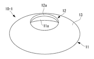
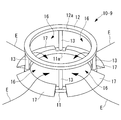
- the space securing device 10-1 is a bowl-shaped member as shown in FIGS.
- the space securing device 10-1 includes a heart pressing portion 11 having a wide-mouthed heart-side opening 11a made of an elastic material such as silicone resin, and a pericardial pressing portion 12 having a narrow-mouthed pericardial-side opening 12a. And an annular connecting portion 13 for connecting them.
- the pericardial opening 12a has a sufficient diameter to allow the distal end of the endoscope 5 to enter the inside from the outside.
- the heart side opening 11a has a sufficient diameter to surround the diseased site D to be observed and treated.
- the connecting portion 13 has an outer surface made of a spherical curved surface that is convex outward.
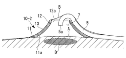
- the space securing device 10-1 according to the present embodiment also has a contracted state that can be accommodated in the sheath 8, and an expanded state in which the space between the surface of the heart A and the pericardium B is expanded by being released from the sheath 8 and expanding. And can be deformed between.
- the space securing device 10-1 In order to observe and treat the disease site D of the heart A using the space securing device 10-1 according to the present embodiment, the space securing device 10-1 is housed in a contracted state as in the first embodiment.
- the sheath 8 is inserted into the pericardial cavity C, and the space securing device 10-1 is pushed out of the sheath 8 so that the heart side opening portion 11a is expanded at a position surrounding the disease site D.
- the heart pressing portion 11 is in close contact with the surface of the heart A, and the heart side opening portion 11a is blocked by the surface of the heart A.
- the pericardial pressing portion 12 is in close contact with the inner surface of the pericardium B, and the pericardial opening 12 a is blocked by the inner surface of the pericardium B.
- the endoscope 5 guided into the pericardial cavity C through the sheath 8 is moved forward on the outer surface of the space securing device 10-1.
- the endoscope 5 is slid between the pericardium B and the pericardial pressing part 12 that have blocked the pericardial opening 12a, and the peripheries of the pericardium It is possible to easily enter the space 7 from the side opening 12a.
- the distal end portion of the endoscope 5 is disposed at a position sufficiently separated from the surface of the heart A, and the bending operation of the bending portion can be freely performed in the space 7. Therefore, there is an advantage that the diseased part D can be easily observed without hindering the operability of the endoscope 5. Furthermore, there is an advantage that treatment with the treatment tool 6 guided separately from the endoscope 5 or through the forceps channel of the endoscope 5 can be easily performed.
- the space securing device 10-1 since the outer surface is formed of a curved surface that is convex outward, the endoscope 5 can be easily curved along the outer surface. Therefore, the operation of the endoscope 5 when entering the pericardial opening 12a can be facilitated.
- the curved surface shape may be concave on the outside.
- the inclination angle of the outer surface of the connecting portion 13 can be suppressed at the position rising from the surface of the heart A, and the endoscope 5 can be easily placed on the outer surface of the space securing device 10-2.
- the space securing devices 10-1 and 10-2 shown in FIGS. 6 and 7 are formed in a thin cylindrical shape, but instead, as shown in FIGS.
- a planar triangular space securing device 10-3 may be employed. Also in this case, you may provide the inclined surface 14 so that it may become thick as an outer surface from an outer peripheral side toward an inner peripheral side.
- annular space securing device 10-4 having a circular or substantially elliptical cross-sectional shape may be employed. Also by these, as shown in FIG. 11, a certain amount of space 7 for the operation of the endoscope 5 can be easily secured between the pericardium B and the surface of the heart A. An ear portion (not shown) that protrudes to the outer peripheral side may be provided so as to be easily gripped at the time of collection.
- a space securing device 10-5 having one or more grooves 15 extending on the outer surface of the connecting portion 13 so as to connect the outer peripheral side and the inner peripheral side is adopted. Also good. By doing in this way, there exists an advantage that the endoscope 5 can be easily guide
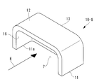
- the space pressing devices 10-6 and 10-7 having a substantially U-shaped configuration may be employed for the heart pressing portion 11 without being closed in an annular shape.
- the space securing device 10-6 may be hollow inside.
- the connecting portion 13 is partially opened to form the opening 16. Therefore, as indicated by an arrow E in the figure, the endoscope 5 and the treatment tool 6 can be made to enter the space 7 surrounded by the space securing device 10 via the opening 16.
- an inclined surface (guiding table) that floats the distal end portion of the endoscope 5 that is allowed to enter the space 7 from the surface of the heart A. 17 may be provided in the heart pressing portion 11.
- a groove 18 is provided on the inclined surface 17.
- FIG. 19 is an example in which an inclined surface 17 is provided on the heart pressing portion 11 so as to float the distal end portion of the endoscope 5 that enters the space 7 from the surface of the heart A.
- the inclined surface 17 may have a groove 18 similar to that shown in FIG.
- the connecting portion 13 may be constituted by a plurality of support columns to constitute a bowl-shaped space securing device 10-9.
- the inclined surface 17 is provided in the heart pressing portion 11 in each opening portion 16 provided between the connecting portions 13 made of struts.
- the space securing device (here, the space securing device 10-6 will be described as an example) includes the space securing device 10-6 including a plurality of small pieces 10a.
- the cross-sectional area is sufficiently small so that it can be easily cut by the forceps F or the like.
- the cut piece 10a of the space securing device 10-6 that has been cut can be easily pulled into the sheath 8 while observing with the endoscope 5. Therefore, there is an advantage that the collection operation can be facilitated.
- the dividing line 19 may be applied to other space securing devices 1, 10-1 to 10-9.
- the space securing devices 1, 10-1 to 10-9 made of an elastic material such as a silicone resin have been described as examples, but instead of this, FIGS. 25 to 30 are used.
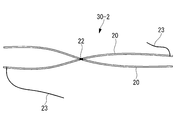
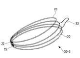
- space securing devices 30-1 to 30-3 configured by wires made of a metal material or a resin material may be employed.
- the space securing device 30-1 shown in FIG. 25 and FIG. 26 has four ring-shaped wires 20 connected to each other by a tube 21 or the like so as to be relatively movable.
- the space securing device 30-1 can be deformed between a contracted state shown in FIG. 26 and an expanded state shown in FIG.
- the space securing device 30-1 can be easily introduced into the pericardial cavity C by the sheath 8 or the like in the contracted state shown in FIG. After being released from the sheath 8, the space securing device 30-1 is in an expanded state as shown in FIG. 25 and is configured to expand the space 7 between the pericardium B and the heart A.
- the wire 20 may be made of a shape memory material.
- the sheath 8 is cooled and maintained in the contracted state shown in FIG. 26, and after being introduced into the pericardial cavity C, the body 8 is brought into the expanded state shown in FIG. You may decide.
- As a cooling method a method using a Peltier element or a low temperature medium such as liquid nitrogen can be sprayed. Furthermore, since it will be in the contracted state of FIG. 26 only by cooling at the time of collection, it can be easily collected.
- FIG. 27 shows the expanded state of the space securing device 30-2.
- the space 7 can be stably formed in the pericardial cavity C when the portion connected by the thread 23 is the heart pressing portion 11 and the joint portion 22 is the pericardial pressing portion 12.
- Such a space securing device 30-2 can be folded small by being folded and can be easily accommodated in the sheath 8.
- the securing device 30-3 may be adopted.
- the space 7 is stably formed in the pericardial cavity C. be able to.
- such a space securing device 30-3 can be folded small by folding and can be easily accommodated in the sheath 8.
- the position surrounded by the broken line G in FIG. 30 is cut with a forceps F or the like, so that the two annular wires 20 are simply stacked. And can be easily collected in the sheath 8.
- FIGS. 31 and 32 a space securing device (here, space securing devices 10-3 and 10-1 will be described as an example) provided with suction means for attracting the heart pressing portion 11 to the surface of the heart A. May be adopted.
- the example shown in FIG. 31 shows the space securing device 10-3 having the suction hole 24 that opens to the contact surface of the heart pressing portion 11 to the surface of the heart A as the suction means.
- a communication hole 25 for supplying a negative pressure and a tube 26 are connected to the suction hole 24.
- the heart pressing portion 11 can be adsorbed and fixed on the surface of the heart A by the adsorption hole 24.
- Observation and treatment can be performed stably by adsorbing and fixing at a desired position surrounding the disease site D.
- a probe 28 having a magnet 27 at the tip is disposed in the heart A, and a magnetic material 29 is disposed on the heart pressing portion 11 of the space securing device 10-1.
- the heart pressing portion 11 can be attracted and fixed to the surface of the heart A by the magnetic attraction generated between the magnet 27 and the magnetic material 29.
- a magnet may be arranged. In this case, either a magnet or a magnetic material may be disposed at the tip of the probe 28.
- a bioadhesive may be used to fix the heart pressing part 11 to the heart A surface.
- a magnet (not shown) that generates a magnetic repulsive force between the magnet 27 and the magnet 27 disposed in the heart A may be disposed in the heart pressing portion 11, or an adhesive, negative pressure suction, gripping, or You may employ
Landscapes
- Health & Medical Sciences (AREA)
- Life Sciences & Earth Sciences (AREA)
- Surgery (AREA)
- Heart & Thoracic Surgery (AREA)
- Animal Behavior & Ethology (AREA)
- General Health & Medical Sciences (AREA)
- Biomedical Technology (AREA)
- Veterinary Medicine (AREA)
- Public Health (AREA)
- Engineering & Computer Science (AREA)
- Molecular Biology (AREA)
- Medical Informatics (AREA)
- Nuclear Medicine, Radiotherapy & Molecular Imaging (AREA)
- Pathology (AREA)
- Child & Adolescent Psychology (AREA)
- Biophysics (AREA)
- Pulmonology (AREA)
- Anesthesiology (AREA)
- Hematology (AREA)
- Oral & Maxillofacial Surgery (AREA)
- Endoscopes (AREA)
Abstract
In a pericardial endoscopic procedure, a space required for handling an endoscope or a treating instrument can be secured, without providing a specific space-securing means to the endoscope or treating instrument or without unnecessarily dilating the pericardiac cavity, so as to improve the handling properties while preventing the onset of a complicating disease such as cardiac tamponade. Disclosed is a space-securing device comprising a pericardium-pressing part for pressing the pericardia from the pericardiac cavity side, a heart-pressing part for pressing the heart surface from the pericardiac cavity side, and a connecting part for connecting said pericardium-pressing part with said heart-pressing part, wherein the connecting part generates an elastic force allowing the dilation against the pressures applied by the pericardia and heart to thereby form a space between said pericardium-pressing part and said heart-pressing part.
Description
本発明は、空間確保デバイスに関するものである。
The present invention relates to a space securing device.
従来、剣状突起の直下から心膜腔に内視鏡および処置具を挿入し、開胸手術を行うことなく、疾患部位(例えば、心筋梗塞部位と正常部位の境界領域)に幹細胞等を注入する心嚢内視鏡手技が知られている(例えば、特許文献1参照。)。
Conventionally, an endoscope and treatment tool are inserted into the pericardial space directly under the xiphoid process, and stem cells are injected into the diseased part (for example, the boundary region between the myocardial infarction part and the normal part) without performing thoracotomy. A pericardial endoscopic technique is known (for example, see Patent Document 1).
しかしながら、特許文献1の心嚢内視鏡手技においては、心膜腔に挿入された内視鏡には、常に、心膜から心臓側に押し付ける力が作用するという不都合がある。すなわち、心膜腔内に挿入された内視鏡によって心臓を観察・処置するためには、心臓の外壁面に対して内視鏡との間に空間を形成する必要がある。しかし、特許文献1の心嚢内視鏡手技においては、内視鏡に作用する心膜からの力によって内視鏡の操作に自由が利かず、操作性が悪いという不都合がある。
However, the pericardial endoscopic technique disclosed in Patent Document 1 has a disadvantage in that the force inserted from the pericardium to the heart always acts on the endoscope inserted into the pericardial cavity. That is, in order to observe and treat the heart with an endoscope inserted into the pericardial cavity, it is necessary to form a space between the outer wall surface of the heart and the endoscope. However, the pericardial endoscopic technique of Patent Document 1 has a disadvantage that the operation from the pericardium acting on the endoscope is not free and the operability is poor.
本発明は上述した事情に鑑みてなされたものであって、心嚢内視鏡手技において、内視鏡や処置具に特別な空間確保手段を設けることなく、かつ、心膜腔を不必要に拡張することなく、内視鏡や処置具の操作に必要な空間を確保して、例えば、心タンポナーデのような合併症を抑えつつ、操作性を向上することができる空間確保デバイスを提供することを目的としている。
The present invention has been made in view of the above-described circumstances, and in pericardial endoscopic procedures, the pericardial cavity is unnecessarily expanded without providing special space securing means in the endoscope or treatment instrument. To provide a space securing device capable of improving the operability while securing a space necessary for operation of an endoscope and a treatment instrument without suppressing complications such as cardiac tamponade, for example. It is aimed.
上記目的を達成するために、本発明は以下の手段を提供する。
本発明は、心膜を心膜腔側から押圧する心膜押圧部と、心臓表面を心膜腔側から押圧する心臓押圧部と、これらを心膜押圧部および心臓押圧部を連結する連結部とを備え、該連結部が前記心膜および前記心臓から受ける圧力に抗して拡張可能な弾発力を発生することにより、前記心膜押圧部と前記心臓押圧部との間に空間を形成する空間確保デバイスを提供する。 In order to achieve the above object, the present invention provides the following means.
The present invention relates to a pericardial pressing part that presses the pericardium from the pericardial cavity side, a cardiac pressing part that presses the heart surface from the pericardial cavity side, and a connecting part that connects the pericardial pressing part and the cardiac pressing part. A space is formed between the pericardial pressing portion and the heart pressing portion by generating a resilient force that can be expanded against the pressure received from the pericardium and the heart. Provide a space securing device.
本発明によれば、連結部の弾発力によって心膜押圧部と心臓押圧部とが相互に離間する方向に押されて拡張される。その結果、心臓表面に対して心膜が引き離されるように移動させられて、心膜押圧部と心臓押圧部との間に空間が形成される。これにより、心膜腔を予め設定された寸法に押し広げ、不必要に拡張することが防止されるとともに、空間内に外部から内視鏡や処置具等を進入させて心膜や心臓によって阻害されることなく内視鏡や処置具を操作することが可能となる。
According to the present invention, the pericardial pressing portion and the heart pressing portion are pushed and expanded in a direction away from each other by the elastic force of the connecting portion. As a result, the pericardium is moved away from the heart surface, and a space is formed between the pericardial pressing part and the cardiac pressing part. This prevents the pericardial cavity from being expanded to a preset size and unnecessarily expanded, and is blocked by the pericardium and heart by allowing an endoscope or treatment tool to enter the space from the outside. The endoscope and the treatment tool can be operated without being performed.
上記発明においては、前記心膜押圧部が板状に形成され、該心膜押圧部の前記心膜に接触する側とは反対側の表面に、照明光を反射する反射面が設けられていてもよい。
このようにすることで、空間確保デバイスを心臓と心膜との間で拡張させた状態で、空間内に進入させた内視鏡の先端部等からの照明光を心膜押圧部に向けて射出することにより、心膜押圧部に設けられている反射面によって照明光が反射されて、反射面に対向している心臓表面に照射される。これにより、照明光の射出端から心臓表面までの距離を確保することができ、過大な拡散光を使用しなくても心臓表面の広い範囲を照明することが可能となる。 In the said invention, the said pericardial press part is formed in plate shape, and the reflective surface which reflects illumination light is provided in the surface on the opposite side to the side which contacts the said pericardium of this pericardial press part. Also good.
In this way, with the space securing device expanded between the heart and the pericardium, the illumination light from the distal end of the endoscope that has entered the space is directed toward the pericardial pressing part. By emitting, the illumination light is reflected by the reflecting surface provided in the pericardial pressing part, and is irradiated on the surface of the heart facing the reflecting surface. Thereby, the distance from the emission end of the illumination light to the heart surface can be secured, and it is possible to illuminate a wide range of the heart surface without using excessive diffused light.
上記発明においては、前記心膜押圧部に、前記空間を前記心膜側に開口させる心膜側開口部が設けられ、前記心臓押圧部に、前記空間を前記心臓側に開口させる心臓側開口部が設けられ、前記連結部が、前記心膜押圧部から前記心臓押圧部に向かって漸次広がる環状に形成された構成でもよい。
In the above invention, the pericardial pressing portion is provided with a pericardial opening that opens the space toward the pericardium, and the cardiac pressing portion opens the space toward the heart. The connecting portion may be formed in an annular shape that gradually spreads from the pericardial pressing portion toward the cardiac pressing portion.
このようにすることで、空間確保デバイスは、心膜腔内に押し出されたときに、心膜押圧部を心膜に接触させ、心臓押圧部を心臓に接触させて、心膜と心臓との距離を広げるように拡張し、内部に空間を形成する。この空間は、心膜側開口部によって心膜側に開口され、心臓側開口部によって心臓側に開口される。心膜押圧部から心臓押圧部に向かって漸次広がる環状に形成された連結部により、心膜腔内に挿入した内視鏡等を連結部の外表面に沿って容易に乗り上げさせ、内視鏡等の先端部を心膜押圧部と心膜との間から心膜側開口部を介して空間内に容易に進入させることができる。これにより、心臓表面から離れた位置に内視鏡等の先端部を配置して心臓表面を観察することができる。
In this way, when the space securing device is pushed into the pericardial cavity, the pericardial pressing part is brought into contact with the pericardium, the cardiac pressing part is brought into contact with the heart, and the pericardium and the heart are in contact with each other. It expands to increase the distance and forms a space inside. This space is opened to the pericardium side by the pericardial side opening and opened to the heart side by the heart side opening. An endoscope inserted into the pericardial cavity can be easily run along the outer surface of the connecting portion by the connecting portion formed in an annular shape gradually spreading from the pericardial pressing portion toward the heart pressing portion. Or the like can easily enter the space from between the pericardial pressing portion and the pericardium through the pericardial opening. As a result, the tip of an endoscope or the like can be placed at a position away from the heart surface to observe the heart surface.
上記構成においては、前記連結部が、少なくとも前記心膜押圧部の近傍において、外側に凸の曲面からなる外表面を有していてもよい。
このようにすることで、連結部の外表面に沿って心膜押圧部の心膜側開口部に進入する内視鏡等を進入し易くすることができる。 In the above-described configuration, the connecting portion may have an outer surface formed of an outwardly convex curved surface at least in the vicinity of the pericardial pressing portion.
By doing in this way, the endoscope etc. which approach into the pericardial side opening part of the pericardial press part along the outer surface of a connection part can be made easy to enter.
上記構成においては、前記連結部が、少なくとも前記心臓押圧部の近傍において、外側に凹の曲面からなる外表面を有していてもよい。
このようにすることで、心臓表面から連結部の外表面にわたって、傾斜角度を徐々に増大させることができ、心膜腔内において心臓の表面に沿って導入された内視鏡等の連結部の外表面への乗り上げ易さを向上することができる。 In the above configuration, the connecting portion may have an outer surface formed of a concave curved surface on the outer side at least in the vicinity of the heart pressing portion.
By doing so, the inclination angle can be gradually increased from the heart surface to the outer surface of the connecting portion, and the connecting portion such as an endoscope introduced along the surface of the heart in the pericardial cavity. The ease of getting on the outer surface can be improved.
上記の凸または凹の曲面からなる外表面を有する構成においては、前記外表面に、前記心臓押圧部の外縁から前記心膜側開口部の内縁まで延びる1以上の溝を備えていてもよい。
このようにすることで、連結部の外表面に乗り上げた内視鏡等を溝に沿って心膜側開口部まで容易に導くことができる。 In the above-described configuration having the convex or concave curved outer surface, the outer surface may be provided with one or more grooves extending from the outer edge of the heart pressing portion to the inner edge of the pericardial opening.
By doing in this way, the endoscope etc. which got on the outer surface of a connection part can be easily guide | induced to the pericardial side opening part along a groove | channel.
上記発明においては、前記心臓押圧部が、前記空間の一部を取り囲む略U字状に形成され、前記連結部に、前記空間内外を連絡する開口部が設けられていてもよい。
このようにすることで、略U字状の心臓押圧部によって心臓表面の処置範囲を取り囲むように空間確保デバイスを配置することができ、連結部に設けられた開口部を介して内視鏡等を空間内に進入させることで、心臓や心膜等に阻害されることなく内視鏡等を操作することが可能となる。 In the said invention, the said heart press part may be formed in the substantially U shape surrounding a part of said space, and the opening part which connects the inside and outside of the said space may be provided in the said connection part.
In this way, the space securing device can be arranged so as to surround the treatment range of the heart surface by the substantially U-shaped heart pressing portion, and an endoscope or the like can be provided via the opening provided in the connecting portion. It is possible to operate the endoscope or the like without being obstructed by the heart, pericardium, or the like.
上記発明においては、前記連結部、前記空間内外を連絡する開口部が設けられ、前記心臓押圧部の少なくとも一部に、前記開口部の外側から内側に向かって高くなる傾斜面を備えていてもよい。
このようにすることで、内視鏡等を空間に進入させる際に傾斜面によって、心臓表面から先端部を浮かせることができ、心臓表面から離れた位置において観察や処置を行うことが可能となる。 In the above-described invention, an opening for connecting the connecting portion and the inside and outside of the space may be provided, and at least a part of the heart pressing portion may include an inclined surface that increases from the outside to the inside of the opening. Good.
By doing so, the tip portion can be lifted from the surface of the heart by the inclined surface when the endoscope or the like enters the space, and observation and treatment can be performed at a position away from the surface of the heart. .
上記発明においては、複数の小片に分割するための複数の分割線を備えていてもよい。
このようにすることで、観察あるいは処置終了後に、拡張した空間確保デバイスを回収する際に、分割線によって容易に複数の小片に分割することができ、回収を容易にすることができる。
また、上記発明においては、生体親和性を有する樹脂材料または金属材料により構成されていてもよい。 In the said invention, you may provide the some dividing line for dividing | segmenting into a some small piece.
By doing so, when the expanded space securing device is recovered after the observation or treatment is completed, it can be easily divided into a plurality of small pieces by the dividing line, and the recovery can be facilitated.
Moreover, in the said invention, you may be comprised with the resin material or metal material which has biocompatibility.
上記発明においては、前記心臓押圧部を、前記心臓の表面に吸着させる吸着手段を備えた構成でもよい。
このようにすることで、吸着手段によって空間確保デバイスを心臓表面に吸着させて安定して固定することができ、内視鏡等の操作時に内視鏡が空間確保デバイスに衝突しても、空間確保デバイスが所望の位置から移動してしまう不都合の発生を防止することができる。 In the said invention, the structure provided with the adsorption | suction means to adsorb | suck the said heart press part on the surface of the said heart may be sufficient.
By doing so, the space securing device can be adsorbed to the heart surface by the adsorbing means and can be stably fixed, and even if the endoscope collides with the space securing device during the operation of the endoscope, It is possible to prevent an inconvenience that the securing device moves from a desired position.
上記構成においては、前記吸着手段が、負圧により心臓押圧部を前記心臓の表面に吸着させてもよい。
上記構成においては、前記吸着手段が、心臓内または前記心臓押圧部のいずれか一方に設けられる磁石と、他方に設けられる磁石または磁性材料とを備えていてもよい。
このようにすることで、空間確保デバイスを心臓表面に簡易かつ安定的に吸着させることができる。 In the above configuration, the suction means may cause the heart pressing portion to be sucked onto the surface of the heart by negative pressure.
In the above configuration, the attracting means may include a magnet provided in one of the heart and the heart pressing portion, and a magnet or a magnetic material provided in the other.
In this way, the space securing device can be easily and stably adsorbed to the heart surface.
上記発明においては、心膜腔内に挿入されるガイドチューブ内に収容可能な収縮状態と、ガイドチューブ外に放出されて拡張する拡張状態との間で変形可能であってもよい。
このようにすることで、心膜腔内にガイドチューブ(シースあるいは内視鏡等)を挿入し、ガイドチューブ内に収縮状態で収容された空間確保デバイスをガイドチューブ外に押し出したときに、ガイドチューブから解放された空間確保デバイスが、心膜腔内においてその弾発力によって拡張状態に復元しようとして拡張し、心臓と心膜との間の隙間を押し広げて内側に空間を形成する。空間は、心臓表面に開口しているとともに、外部から進入できる。したがって、形成された空間内に外部から内視鏡の先端部や処置具を進入させることで、内視鏡や処置具の動作が心膜や心臓によって阻害されることを防止して、操作性を向上することができる。 In the said invention, it may deform | transform between the contracted state which can be accommodated in the guide tube inserted in a pericardial cavity, and the expanded state which is discharge | released out of a guide tube and expands.
In this way, when a guide tube (sheath or endoscope, etc.) is inserted into the pericardial cavity and the space securing device housed in the guide tube in a contracted state is pushed out of the guide tube, the guide The space securing device released from the tube expands in the pericardial space in an attempt to restore its expanded state by its elastic force, and widens the gap between the heart and the pericardium to form a space inside. The space is open to the heart surface and is accessible from the outside. Therefore, the operation of the endoscope and the treatment tool is prevented from being obstructed by the pericardium and the heart by allowing the distal end of the endoscope and the treatment tool to enter from the outside into the formed space. Can be improved.
本発明によれば、心嚢内視鏡手技において、内視鏡や処置具に特別な空間確保手段を設けることなく、かつ、心膜腔を不必要に拡張することなく、内視鏡や処置具の操作に必要な空間を確保して、例えば、心タンポナーデのような合併症を抑えつつ、操作性を向上することができるという効果を奏する。
According to the present invention, in the pericardial endoscopic procedure, the endoscope and the treatment tool are provided without providing a special space securing means in the endoscope and the treatment tool and without unnecessarily expanding the pericardial cavity. As a result, it is possible to secure a space necessary for the above operation and to improve operability while suppressing complications such as cardiac tamponade.
本発明の第1の実施形態に係る空間確保デバイス1について、図面を参照して以下に説明する。
本実施形態に係る空間確保デバイス1は、図1に示されるように、心臓Aと心膜Bとの間に配置される心膜腔C内に配置されて、心臓Aと心膜Bとの間隔を広げるデバイスである。 Aspace securing device 1 according to a first embodiment of the present invention will be described below with reference to the drawings.
As shown in FIG. 1, thespace securing device 1 according to the present embodiment is disposed in a pericardial cavity C that is disposed between the heart A and the pericardium B. A device that widens the spacing.
本実施形態に係る空間確保デバイス1は、図1に示されるように、心臓Aと心膜Bとの間に配置される心膜腔C内に配置されて、心臓Aと心膜Bとの間隔を広げるデバイスである。 A
As shown in FIG. 1, the
本実施形態に係る空間確保デバイス1は、シリコーン樹脂等の拡張・収縮可能な弾性材料により構成されている。空間確保デバイス1は、心臓A表面に接触する心臓押圧部2と、心膜B内面に接触する心膜押圧部3と、これらを連結する連結部4とを備えた一体的な部材である。
心臓押圧部2は、図4に示されるように、略U字状の平板部分である。心臓押圧部2は、内視鏡5により観察し、処置具6により処置しようとする範囲(例えば、疾患部位D)の周囲を部分的に取り囲む位置に配置される。 Thespace securing device 1 according to the present embodiment is made of an elastic material that can be expanded and contracted, such as silicone resin. The space securing device 1 is an integral member including a heart pressing portion 2 that contacts the surface of the heart A, a pericardial pressing portion 3 that contacts the inner surface of the pericardium B, and a connecting portion 4 that connects them.
As shown in FIG. 4, theheart pressing portion 2 is a substantially U-shaped flat plate portion. The heart pressing unit 2 is disposed at a position that partially surrounds the periphery of the range (for example, diseased site D) to be treated by the treatment tool 6 while being observed with the endoscope 5.
心臓押圧部2は、図4に示されるように、略U字状の平板部分である。心臓押圧部2は、内視鏡5により観察し、処置具6により処置しようとする範囲(例えば、疾患部位D)の周囲を部分的に取り囲む位置に配置される。 The
As shown in FIG. 4, the
心膜押圧部3は、図4に示されるように、例えば矩形状の平板部分である。心膜押圧部3は、図1に示されるように、外側面によって心膜Bを押圧する。また、図1に示されるように、心膜押圧部3の外側面とは反対側の面は反射膜3aによってコーティングされていて、光Lを反射することができるようになっている。
The pericardial pressing part 3 is, for example, a rectangular flat plate part as shown in FIG. As shown in FIG. 1, the pericardial pressing unit 3 presses the pericardium B with the outer surface. As shown in FIG. 1, the surface opposite to the outer surface of the pericardial pressing portion 3 is coated with a reflective film 3a so that the light L can be reflected.
連結部4は、心臓押圧部2と心膜押圧部3とをそれぞれの一端どうしを連結する部分である。連結部4は、内視鏡5を挿入可能な貫通孔4aと、処置具6を挿入可能な貫通孔4bとを備えている。
内視鏡5用の貫通孔4aは、空間確保デバイス1の外側から心臓押圧部2と心膜押圧部3との間に形成される空間7内に向かって、心臓押圧部2から離れる方向に傾斜している。これにより、外側から挿入された内視鏡5の先端面5aを容易に斜め上向きに配することができるようになっている。処置具6用の貫通孔4bは、空間確保デバイス1の外側から空間7内に向かって、心膜押圧部3から離れる方向に傾斜していてもよい。 The connectingpart 4 is a part that connects the one end of the heart pressing part 2 and the pericardial pressing part 3. The connecting portion 4 includes a through hole 4a into which the endoscope 5 can be inserted, and a through hole 4b into which the treatment tool 6 can be inserted.
The through-hole 4a for the endoscope 5 extends from the outside of the space securing device 1 into the space 7 formed between the heart pressing part 2 and the pericardial pressing part 3 in a direction away from the heart pressing part 2. Inclined. Thereby, the front end surface 5a of the endoscope 5 inserted from the outside can be easily arranged obliquely upward. The through-hole 4b for the treatment instrument 6 may be inclined in a direction away from the pericardial pressing portion 3 from the outside of the space securing device 1 into the space 7.
内視鏡5用の貫通孔4aは、空間確保デバイス1の外側から心臓押圧部2と心膜押圧部3との間に形成される空間7内に向かって、心臓押圧部2から離れる方向に傾斜している。これにより、外側から挿入された内視鏡5の先端面5aを容易に斜め上向きに配することができるようになっている。処置具6用の貫通孔4bは、空間確保デバイス1の外側から空間7内に向かって、心膜押圧部3から離れる方向に傾斜していてもよい。 The connecting
The through-
本実施形態に係る空間確保デバイス1は、図2に示されるように、例えば、剣状突起下部から心膜腔C内に挿入されたシース(ガイドチューブ)8内に収容可能な収縮状態と、図3に示されるように、シース8内に基端側から挿入される押し出し棒9によって、シース8内から押し出されることにより解放された拡張状態との間で伸縮可能である。空間確保デバイス1は、拡張状態では、予め設定された弾発力によって拡張する。したがって、空間確保デバイス1は、心膜Bと心臓Aとの間隔を不必要に拡張することなく、十分な空間7を形成するようになっている。
As shown in FIG. 2, the space securing device 1 according to the present embodiment includes, for example, a contracted state that can be accommodated in a sheath (guide tube) 8 inserted into the pericardial cavity C from the lower part of the xiphoid process, As shown in FIG. 3, the push rod 9 inserted into the sheath 8 from the proximal end side can be expanded and contracted between the expanded state released by being pushed out of the sheath 8. In the expanded state, the space securing device 1 is expanded by a preset elasticity. Therefore, the space securing device 1 forms a sufficient space 7 without unnecessarily expanding the interval between the pericardium B and the heart A.
このように構成された本実施形態に係る空間確保デバイス1の作用について以下に説明する。
本実施形態に係る空間確保デバイス1を用いて心臓Aの疾患部位D(例えば、心筋梗塞部位と正常部位との境界領域)を観察しつつ、幹細胞等を注入する処置を行うには、先端部分近傍に空間確保デバイス1を収縮させた状態で収容したシース8の先端部を、剣状突起下部等から、図2に示されるように心膜腔C内に挿入する。この状態では、心膜Bと心臓Aとが離間させられている領域はシース8の先端部近傍に限定されている。 The operation of thespace securing device 1 according to this embodiment configured as described above will be described below.
To perform a procedure of injecting stem cells or the like while observing a diseased part D of the heart A (for example, a boundary region between a myocardial infarction part and a normal part) using thespace securing device 1 according to the present embodiment, The distal end portion of the sheath 8 accommodated in a state where the space securing device 1 is contracted in the vicinity is inserted into the pericardial cavity C as shown in FIG. In this state, the region where the pericardium B and the heart A are separated is limited to the vicinity of the distal end portion of the sheath 8.
本実施形態に係る空間確保デバイス1を用いて心臓Aの疾患部位D(例えば、心筋梗塞部位と正常部位との境界領域)を観察しつつ、幹細胞等を注入する処置を行うには、先端部分近傍に空間確保デバイス1を収縮させた状態で収容したシース8の先端部を、剣状突起下部等から、図2に示されるように心膜腔C内に挿入する。この状態では、心膜Bと心臓Aとが離間させられている領域はシース8の先端部近傍に限定されている。 The operation of the
To perform a procedure of injecting stem cells or the like while observing a diseased part D of the heart A (for example, a boundary region between a myocardial infarction part and a normal part) using the
この状態で、シース8の基端側から導入した押し出し棒9によって、シース8内に収容されている空間確保デバイス1を、図3に示されるように、シース8外に押し出す。このとき、心臓押圧部2が、図4に示されるように疾患部位Dを取り囲む位置に配置する。空間確保デバイス1は、弾性材料により構成されているので、その弾発力によって拡張する。これにより、心膜押圧部3によって心膜Bが押圧され、心臓押圧部2によって心臓Aが押圧され、疾患部位Dの近傍において心膜Bと心臓Aとの間隔を拡大することができる。
In this state, the space securing device 1 accommodated in the sheath 8 is pushed out of the sheath 8 by the push rod 9 introduced from the proximal end side of the sheath 8 as shown in FIG. At this time, the heart pressing part 2 is arranged at a position surrounding the disease site D as shown in FIG. Since the space securing device 1 is made of an elastic material, it is expanded by its elastic force. As a result, the pericardium B is pressed by the pericardial pressing unit 3 and the heart A is pressed by the cardiac pressing unit 2, so that the interval between the pericardial B and the heart A can be enlarged in the vicinity of the diseased site D.
このとき、空間確保デバイス1は、拡張状態では、予め設定された弾発力によって拡張する。したがって、心膜Bと心臓Aとの間隔を不必要に拡張することなく、十分な空間7を形成することができる。
この後に、シース8内を介して内視鏡5および処置具6を心膜腔C内に導く。そして、連結部4に設けられた心臓A側の貫通孔4aから内視鏡5を、心膜B側の貫通孔4bから処置具6を、それぞれ心臓押圧部2と心膜押圧部3との間に形成された空間7内に挿入する。 At this time, thespace securing device 1 is expanded by a preset elasticity in the expanded state. Therefore, a sufficient space 7 can be formed without unnecessarily expanding the interval between the pericardium B and the heart A.
Thereafter, theendoscope 5 and the treatment tool 6 are guided into the pericardial cavity C through the sheath 8. The endoscope 5 is inserted from the heart A side through-hole 4 a provided in the connecting portion 4, the treatment tool 6 is inserted from the pericardium B-side through hole 4 b, and the heart pressing unit 2 and the pericardial pressing unit 3. It inserts in the space 7 formed between.
この後に、シース8内を介して内視鏡5および処置具6を心膜腔C内に導く。そして、連結部4に設けられた心臓A側の貫通孔4aから内視鏡5を、心膜B側の貫通孔4bから処置具6を、それぞれ心臓押圧部2と心膜押圧部3との間に形成された空間7内に挿入する。 At this time, the
Thereafter, the
内視鏡5用の貫通孔4aは空間7内に向かって心臓押圧部2から離れる方向に傾斜している。したがって、貫通孔4aに挿入された内視鏡5はその先端面5aが斜め上方に向かうように容易に導かれる。そして、図1に示されるように、先端面5aから照明光を照射する。照明光は、心膜押圧部3に設けられた反射面3aによって心臓A表面側に反射され、心臓A表面を照明する。一方、心臓A表面から戻る蛍光や反射光のような戻り光は、反射面3aを介して内視鏡5の先端面5aに設けられた図示しない対物レンズによって集光される。
The through hole 4a for the endoscope 5 is inclined in a direction away from the heart pressing portion 2 toward the space 7. Therefore, the endoscope 5 inserted into the through hole 4a is easily guided so that the distal end surface 5a is directed obliquely upward. And as FIG. 1 shows, illumination light is irradiated from the front end surface 5a. The illumination light is reflected to the surface side of the heart A by the reflecting surface 3a provided on the pericardial pressing part 3, and illuminates the surface of the heart A. On the other hand, return light such as fluorescence and reflected light returning from the surface of the heart A is collected by an objective lens (not shown) provided on the distal end surface 5a of the endoscope 5 via the reflection surface 3a.
この場合において、内視鏡5の先端面5aから心臓A表面までの光路は反射面3aによって折り返される。これにより、心膜Bと心臓Aとの間隔を必要以上に広げなくても、内視鏡5の先端面5aから心臓A表面までの距離を確保することができる。したがって、照明光を過度に拡散させなくても疾患部位Dを十分に照明し、観察することができる。その結果、例えば、心タンポナーデのような合併症を抑えることができる。
In this case, the optical path from the distal end surface 5a of the endoscope 5 to the surface of the heart A is folded back by the reflecting surface 3a. Thereby, the distance from the distal end surface 5a of the endoscope 5 to the surface of the heart A can be ensured without increasing the distance between the pericardium B and the heart A more than necessary. Therefore, the diseased part D can be sufficiently illuminated and observed without excessively diffusing the illumination light. As a result, complications such as cardiac tamponade can be suppressed.
そして、この状態で、図1に示されるように、連結部4の心膜B側の貫通孔4bを介して空間7内に進入させた処置具6を内視鏡5によって観察しながら、処置具6の先端の注射針6aを疾患部位Dと正常部位との境界領域に確実に穿刺して、幹細胞等を注入することができる。
観察および処置を終えた後には、シース8内を介して導入した鉗子(図示略)によって空間確保デバイス1を把持し、変形させながらシース8内に引き込むことにより、容易に回収することができる。 In this state, as shown in FIG. 1, while observing thetreatment tool 6 that has entered the space 7 through the through-hole 4 b on the pericardium B side of the connecting portion 4 with the endoscope 5, Stem cells and the like can be injected by reliably puncturing the injection needle 6a at the tip of the tool 6 in the boundary region between the diseased site D and the normal site.
After the observation and treatment are finished, thespace securing device 1 is grasped by forceps (not shown) introduced through the inside of the sheath 8 and pulled into the sheath 8 while being deformed, so that it can be easily recovered.
観察および処置を終えた後には、シース8内を介して導入した鉗子(図示略)によって空間確保デバイス1を把持し、変形させながらシース8内に引き込むことにより、容易に回収することができる。 In this state, as shown in FIG. 1, while observing the
After the observation and treatment are finished, the
本実施形態において、処置具6を挿入する貫通孔4bとして、空間確保デバイス1の外側から空間7内に向かって、心膜押圧部3から離れる方向に傾斜させることにより、処置具6の先端の注射針6aを疾患部位Dに向かわせ易くすることができるという利点がある。
また、本実施形態においては、反射面3aによって疾患部位Dを含む領域からの戻り光を反射させているため、取得される画像としては反転した画像となる。そこで、内視鏡5の基端側に接続された画像処理部(図示略)によって画像反転処理を行うことが好ましい。 In the present embodiment, the through-hole 4b into which the treatment tool 6 is inserted is inclined in the direction away from the pericardial pressing portion 3 from the outside of the space securing device 1 into the space 7, thereby There is an advantage that the injection needle 6a can be easily directed to the diseased site D.
Moreover, in this embodiment, since the return light from the area | region containing the disease site | part D is reflected by thereflective surface 3a, it becomes an inverted image as an acquired image. Therefore, it is preferable to perform image inversion processing by an image processing unit (not shown) connected to the proximal end side of the endoscope 5.
また、本実施形態においては、反射面3aによって疾患部位Dを含む領域からの戻り光を反射させているため、取得される画像としては反転した画像となる。そこで、内視鏡5の基端側に接続された画像処理部(図示略)によって画像反転処理を行うことが好ましい。 In the present embodiment, the through-
Moreover, in this embodiment, since the return light from the area | region containing the disease site | part D is reflected by the
また、本実施形態においては、全体がシリコーン樹脂により構成されている場合を例示したが、これに代えて、他の弾性材料、例えば、ポリウレタン樹脂等により構成してもよい。また、心臓Aおよび心膜Bとのコンプライアンスを調整することにより、本実施形態に係る空間確保デバイス1を心臓Aの拍動や呼吸の影響により加わる力を抑制する部材として機能させることもできる。すなわち、心臓Aに接する心臓押圧部2は柔らかくて復元しやすいシリコーン樹脂やポリウレタン樹脂等により構成し、心膜Bに接する心膜押圧部3は硬く変形しにくい材料、例えば、PTFEやポリエチレン等により構成してもよい。また、その逆の構成としてもよい。
Further, in the present embodiment, the case where the entirety is made of a silicone resin has been illustrated, but instead, it may be made of another elastic material such as a polyurethane resin. Further, by adjusting the compliance with the heart A and the pericardium B, the space securing device 1 according to the present embodiment can be made to function as a member that suppresses the force applied by the pulsation of the heart A or the influence of respiration. That is, the heart pressing part 2 in contact with the heart A is made of a soft and easy-to-restore silicone resin or polyurethane resin, and the pericardial pressing part 3 in contact with the pericardium B is made of a hard and hardly deformable material such as PTFE or polyethylene. It may be configured. Moreover, it is good also as a reverse structure.
また、シース8内に収容した収縮状態の空間確保デバイス1をシース8から押し出すことにより心膜腔C内で拡張させることとしたが、これに代えて、内視鏡5に備えられた鉗子チャネル(図示略)に収容した収縮状態の空間確保デバイス1を鉗子チャネルから押し出すこととしてもよい。
In addition, the contracted space securing device 1 accommodated in the sheath 8 is expanded from the sheath 8 by being pushed out from the sheath 8, but instead of this, a forceps channel provided in the endoscope 5 is used. The contracted space securing device 1 accommodated in (not shown) may be pushed out from the forceps channel.
また、空間確保デバイス1を構成するシリコーン樹脂等の中に、X線不透過な材料が混合されていることが好ましい。このようにすることで、X線透視画像によって心膜腔C内における位置を容易に確認することができる。
Further, it is preferable that an X-ray opaque material is mixed in the silicone resin or the like constituting the space securing device 1. By doing in this way, the position in the pericardial cavity C can be easily confirmed by an X-ray fluoroscopic image.
次に、本発明の第2の実施形態に係る空間確保デバイス10-1について、図面を参照して以下に説明する。
本実施形態に係る空間確保デバイス10-1の説明において、上述した第1の実施形態に係る空間確保デバイス1と構成を共通とする箇所には同一符号を付して説明を省略する。 Next, a space securing device 10-1 according to a second embodiment of the present invention will be described below with reference to the drawings.
In the description of the space securing device 10-1 according to the present embodiment, portions having the same configuration as thespace securing device 1 according to the first embodiment described above are denoted by the same reference numerals and description thereof is omitted.
本実施形態に係る空間確保デバイス10-1の説明において、上述した第1の実施形態に係る空間確保デバイス1と構成を共通とする箇所には同一符号を付して説明を省略する。 Next, a space securing device 10-1 according to a second embodiment of the present invention will be described below with reference to the drawings.
In the description of the space securing device 10-1 according to the present embodiment, portions having the same configuration as the
本実施形態に係る空間確保デバイス10-1は、図5および図6に示されるように、椀型の部材である。空間確保デバイス10-1は、シリコーン樹脂等の弾性材料によって構成された広口の心臓側開口部11aを有する心臓押圧部11と、狭口の心膜側開口部12aを有する心膜押圧部12と、これらを連結する円環状の連結部13とを備えている。
The space securing device 10-1 according to the present embodiment is a bowl-shaped member as shown in FIGS. The space securing device 10-1 includes a heart pressing portion 11 having a wide-mouthed heart-side opening 11a made of an elastic material such as silicone resin, and a pericardial pressing portion 12 having a narrow-mouthed pericardial-side opening 12a. And an annular connecting portion 13 for connecting them.
心膜側開口部12aは、内視鏡5の先端部を外部から内部に進入させるのに十分な口径を有している。心臓側開口部11aは、観察および処置すべき疾患部位Dを取り囲むのに十分な口径を有している。
連結部13は、外側に凸の球面状の曲面からなる外表面を有している。
本実施形態に係る空間確保デバイス10-1も、シース8内に収容可能な収縮状態と、シース8内から解放されて拡張し、心臓A表面と心膜Bとの間の間隔を広げる拡張状態との間で変形可能である。 Thepericardial opening 12a has a sufficient diameter to allow the distal end of the endoscope 5 to enter the inside from the outside. The heart side opening 11a has a sufficient diameter to surround the diseased site D to be observed and treated.
The connectingportion 13 has an outer surface made of a spherical curved surface that is convex outward.
The space securing device 10-1 according to the present embodiment also has a contracted state that can be accommodated in thesheath 8, and an expanded state in which the space between the surface of the heart A and the pericardium B is expanded by being released from the sheath 8 and expanding. And can be deformed between.
連結部13は、外側に凸の球面状の曲面からなる外表面を有している。
本実施形態に係る空間確保デバイス10-1も、シース8内に収容可能な収縮状態と、シース8内から解放されて拡張し、心臓A表面と心膜Bとの間の間隔を広げる拡張状態との間で変形可能である。 The
The connecting
The space securing device 10-1 according to the present embodiment also has a contracted state that can be accommodated in the
このように構成された本実施形態に係る空間確保デバイス10-1の作用について、以下に説明する。
本実施形態に係る空間確保デバイス10-1を用いて心臓Aの疾患部位Dの観察および処置を行うには、第1の実施形態と同様に、空間確保デバイス10-1を収縮状態で収容したシース8を心膜腔C内に挿入し、シース8内から空間確保デバイス10-1を押し出すことにより、心臓側開口部11aが疾患部位Dを取り囲む位置において拡張させる。これにより、心臓押圧部11が心臓A表面に密着して心臓側開口部11aが心臓A表面によって塞がれる。一方、心膜押圧部12が心膜B内面に密着して心膜側開口部12aが心膜B内面によって塞がれる。 The operation of the space securing device 10-1 according to the present embodiment configured as described above will be described below.
In order to observe and treat the disease site D of the heart A using the space securing device 10-1 according to the present embodiment, the space securing device 10-1 is housed in a contracted state as in the first embodiment. Thesheath 8 is inserted into the pericardial cavity C, and the space securing device 10-1 is pushed out of the sheath 8 so that the heart side opening portion 11a is expanded at a position surrounding the disease site D. As a result, the heart pressing portion 11 is in close contact with the surface of the heart A, and the heart side opening portion 11a is blocked by the surface of the heart A. On the other hand, the pericardial pressing portion 12 is in close contact with the inner surface of the pericardium B, and the pericardial opening 12 a is blocked by the inner surface of the pericardium B.
本実施形態に係る空間確保デバイス10-1を用いて心臓Aの疾患部位Dの観察および処置を行うには、第1の実施形態と同様に、空間確保デバイス10-1を収縮状態で収容したシース8を心膜腔C内に挿入し、シース8内から空間確保デバイス10-1を押し出すことにより、心臓側開口部11aが疾患部位Dを取り囲む位置において拡張させる。これにより、心臓押圧部11が心臓A表面に密着して心臓側開口部11aが心臓A表面によって塞がれる。一方、心膜押圧部12が心膜B内面に密着して心膜側開口部12aが心膜B内面によって塞がれる。 The operation of the space securing device 10-1 according to the present embodiment configured as described above will be described below.
In order to observe and treat the disease site D of the heart A using the space securing device 10-1 according to the present embodiment, the space securing device 10-1 is housed in a contracted state as in the first embodiment. The
その後に、シース8を介して心膜腔C内に導いた内視鏡5を空間確保デバイス10-1の外表面に乗り上げさせて前進させる。これにより、図6に示されるように、心膜側開口部12aを閉塞していた心膜Bと心膜押圧部12との間に内視鏡5を滑り込ませて、その先端部を心膜側開口部12aから空間7内に容易に進入させることができる。
Thereafter, the endoscope 5 guided into the pericardial cavity C through the sheath 8 is moved forward on the outer surface of the space securing device 10-1. As a result, as shown in FIG. 6, the endoscope 5 is slid between the pericardium B and the pericardial pressing part 12 that have blocked the pericardial opening 12a, and the peripheries of the pericardium It is possible to easily enter the space 7 from the side opening 12a.
これにより、内視鏡5の先端部は、心臓A表面から十分に離間した位置に配置され、その湾曲部の湾曲動作を空間7内において自由に行うことができる。したがって、内視鏡5の操作性が阻害されることなく、疾患部位Dの観察を容易に行なうことができるという利点がある。さらに、内視鏡5とは別個に、または内視鏡5の鉗子チャネルを介して導いた処置具6による処置を容易に行うことができるという利点がある。
Thereby, the distal end portion of the endoscope 5 is disposed at a position sufficiently separated from the surface of the heart A, and the bending operation of the bending portion can be freely performed in the space 7. Therefore, there is an advantage that the diseased part D can be easily observed without hindering the operability of the endoscope 5. Furthermore, there is an advantage that treatment with the treatment tool 6 guided separately from the endoscope 5 or through the forceps channel of the endoscope 5 can be easily performed.
また、本実施形態に係る空間確保デバイス10-1によれば、その外表面が外側に凸の曲面により構成されているので、内視鏡5を外表面に倣って湾曲させ易い。したがって心膜側開口部12aに進入する際の内視鏡5の操作を容易にすることができる。
Further, according to the space securing device 10-1 according to the present embodiment, since the outer surface is formed of a curved surface that is convex outward, the endoscope 5 can be easily curved along the outer surface. Therefore, the operation of the endoscope 5 when entering the pericardial opening 12a can be facilitated.
なお、外側に凸の曲面形状に代えて、図7に示されるように、外側に凹の曲面形状を有することにしてもよい。
このようにすることで、心臓A表面から立ち上がる位置において連結部13の外表面の傾斜角度を抑えることができ、内視鏡5を空間確保デバイス10-2の外表面に乗り上げさせ易くすることができるという利点がある。 In addition, instead of the convex curved shape on the outside, as shown in FIG. 7, the curved surface shape may be concave on the outside.
By doing so, the inclination angle of the outer surface of the connectingportion 13 can be suppressed at the position rising from the surface of the heart A, and the endoscope 5 can be easily placed on the outer surface of the space securing device 10-2. There is an advantage that you can.
このようにすることで、心臓A表面から立ち上がる位置において連結部13の外表面の傾斜角度を抑えることができ、内視鏡5を空間確保デバイス10-2の外表面に乗り上げさせ易くすることができるという利点がある。 In addition, instead of the convex curved shape on the outside, as shown in FIG. 7, the curved surface shape may be concave on the outside.
By doing so, the inclination angle of the outer surface of the connecting
また、図6および図7に示される空間確保デバイス10-1,10-2は、薄肉の筒状に形成しているが、これに代えて、図8および図9に示されるように、横断面3角形の円環状の空間確保デバイス10-3を採用してもよい。この場合も、外表面として外周側から内周側に向かって肉厚になるように、傾斜面14を備えていてもよい。
Moreover, the space securing devices 10-1 and 10-2 shown in FIGS. 6 and 7 are formed in a thin cylindrical shape, but instead, as shown in FIGS. A planar triangular space securing device 10-3 may be employed. Also in this case, you may provide the inclined surface 14 so that it may become thick as an outer surface from an outer peripheral side toward an inner peripheral side.
また、図10に示されるように、単に円形あるいは略楕円形の横断面形状を有する円環状の空間確保デバイス10-4を採用してもよい。これらによっても、図11に示されるように、内視鏡5の操作用のある程度の空間7を心膜Bと心臓A表面との間に容易に確保することができる。回収時に把持し易いように、外周側に突出する耳部(図示略)を設けることにしてもよい。
Further, as shown in FIG. 10, an annular space securing device 10-4 having a circular or substantially elliptical cross-sectional shape may be employed. Also by these, as shown in FIG. 11, a certain amount of space 7 for the operation of the endoscope 5 can be easily secured between the pericardium B and the surface of the heart A. An ear portion (not shown) that protrudes to the outer peripheral side may be provided so as to be easily gripped at the time of collection.
また、図12および図13に示されるように、連結部13の外表面に、外周側と内周側とを結ぶように延びる1以上の溝15を有する空間確保デバイス10-5を採用してもよい。このようにすることで、内視鏡5を心膜側開口部12aから内部の空間7に容易に導くことができるという利点がある。
Further, as shown in FIGS. 12 and 13, a space securing device 10-5 having one or more grooves 15 extending on the outer surface of the connecting portion 13 so as to connect the outer peripheral side and the inner peripheral side is adopted. Also good. By doing in this way, there exists an advantage that the endoscope 5 can be easily guide | induced to the internal space 7 from the pericardial side opening part 12a.
また、図14および図15に示されるように、心臓押圧部11が、円環状に閉じずに、略U字状の形態を有する空間確保デバイス10-6,10-7を採用してもよい。空間確保デバイス10-6は、内部が空洞になっていてもよい。
この場合には、連結部13が部分的に開放されて開口部16が形成される。したがって、図中に矢印Eで示されるように、内視鏡5や処置具6をその開口部16を経由して空間確保デバイス10により囲まれた空間7に進入させることができる。 Further, as shown in FIGS. 14 and 15, the space pressing devices 10-6 and 10-7 having a substantially U-shaped configuration may be employed for theheart pressing portion 11 without being closed in an annular shape. . The space securing device 10-6 may be hollow inside.
In this case, the connectingportion 13 is partially opened to form the opening 16. Therefore, as indicated by an arrow E in the figure, the endoscope 5 and the treatment tool 6 can be made to enter the space 7 surrounded by the space securing device 10 via the opening 16.
この場合には、連結部13が部分的に開放されて開口部16が形成される。したがって、図中に矢印Eで示されるように、内視鏡5や処置具6をその開口部16を経由して空間確保デバイス10により囲まれた空間7に進入させることができる。 Further, as shown in FIGS. 14 and 15, the space pressing devices 10-6 and 10-7 having a substantially U-shaped configuration may be employed for the
In this case, the connecting
また、図16および図17に示されるように、空間確保デバイス10-7においては、空間7内に進入させられる内視鏡5の先端部を心臓A表面から浮かせるような傾斜面(誘い台)17を心臓押圧部11に設けることにしてもよい。図17に示される例では、その傾斜面17に溝18が設けられている。内視鏡5や処置具6を溝18に保持させることで、操作の際に安定させることができる。
Also, as shown in FIGS. 16 and 17, in the space securing device 10-7, an inclined surface (guiding table) that floats the distal end portion of the endoscope 5 that is allowed to enter the space 7 from the surface of the heart A. 17 may be provided in the heart pressing portion 11. In the example shown in FIG. 17, a groove 18 is provided on the inclined surface 17. By holding the endoscope 5 and the treatment tool 6 in the groove 18, it is possible to stabilize the operation.
また、略U字状の心臓押圧部11を、円形のみならず、図18および図19のように矩形にした空間確保デバイス10-8を採用してもよい。図19は、空間7内に進入させられる内視鏡5の先端部を心臓A表面から浮かせるような傾斜面17を心臓押圧部11に設けた例である。傾斜面17は図17と同様の溝18を有していてもよい。
Further, a space securing device 10-8 in which the substantially U-shaped heart pressing portion 11 is not only circular but rectangular as shown in FIGS. 18 and 19 may be adopted. FIG. 19 is an example in which an inclined surface 17 is provided on the heart pressing portion 11 so as to float the distal end portion of the endoscope 5 that enters the space 7 from the surface of the heart A. The inclined surface 17 may have a groove 18 similar to that shown in FIG.
また、図20および図21に示されるように、連結部13を複数の支柱によって構成し、籠状の空間確保デバイス10-9を構成してもよい。図20および図21に示される例では、支柱からなる連結部13の間に設けられた各開口部16には心臓押圧部11に傾斜面17がそれぞれ設けられている。これにより、内部の空間7に進入させる際の内視鏡5等を心臓A表面から浮かせることができる。
Further, as shown in FIGS. 20 and 21, the connecting portion 13 may be constituted by a plurality of support columns to constitute a bowl-shaped space securing device 10-9. In the example shown in FIG. 20 and FIG. 21, the inclined surface 17 is provided in the heart pressing portion 11 in each opening portion 16 provided between the connecting portions 13 made of struts. Thereby, the endoscope 5 and the like when entering the internal space 7 can be floated from the surface of the heart A.
また、図23および図24に示されるように、空間確保デバイス(ここでは、空間確保デバイス10-6を例に挙げて説明する。)には、該空間確保デバイス10-6を複数の小片10aに分割するための分割線19を有するものを採用してもよい。この分割線19位置においては、その横断面積を十分に小さくしており、鉗子F等によって簡易に切断することができるようになっている。切断した空間確保デバイス10-6の小片10aは、図24に示されるように、内視鏡5によって観察しながら、シース8内に容易に引き込むことができる。したがって、回収作業を容易にすることができるという利点がある。分割線19は他の空間確保デバイス1,10-1~10-9に適用してもよい。
As shown in FIGS. 23 and 24, the space securing device (here, the space securing device 10-6 will be described as an example) includes the space securing device 10-6 including a plurality of small pieces 10a. You may employ | adopt what has the dividing line 19 for dividing | segmenting into. At the position of the dividing line 19, the cross-sectional area is sufficiently small so that it can be easily cut by the forceps F or the like. As shown in FIG. 24, the cut piece 10a of the space securing device 10-6 that has been cut can be easily pulled into the sheath 8 while observing with the endoscope 5. Therefore, there is an advantage that the collection operation can be facilitated. The dividing line 19 may be applied to other space securing devices 1, 10-1 to 10-9.
また、上記各実施形態においては、シリコーン樹脂等の弾性材料によって構成された空間確保デバイス1,10-1~10-9を例示に挙げて説明したが、これに代えて、図25~図30に示されるように、金属材料あるいは樹脂材料からなるワイヤによって構成された空間確保デバイス30-1~30-3を採用してもよい。
例えば、図25および図26に示される空間確保デバイス30-1は、4本のリング状のワイヤ20をチューブ21等で相対移動可能に接続したものである。空間確保デバイス30-1は、図26に示される収縮状態と図25に示される拡張状態との間で変形することができるようになっている。 In each of the above embodiments, thespace securing devices 1, 10-1 to 10-9 made of an elastic material such as a silicone resin have been described as examples, but instead of this, FIGS. 25 to 30 are used. As shown in FIG. 4, space securing devices 30-1 to 30-3 configured by wires made of a metal material or a resin material may be employed.
For example, the space securing device 30-1 shown in FIG. 25 and FIG. 26 has four ring-shapedwires 20 connected to each other by a tube 21 or the like so as to be relatively movable. The space securing device 30-1 can be deformed between a contracted state shown in FIG. 26 and an expanded state shown in FIG.
例えば、図25および図26に示される空間確保デバイス30-1は、4本のリング状のワイヤ20をチューブ21等で相対移動可能に接続したものである。空間確保デバイス30-1は、図26に示される収縮状態と図25に示される拡張状態との間で変形することができるようになっている。 In each of the above embodiments, the
For example, the space securing device 30-1 shown in FIG. 25 and FIG. 26 has four ring-shaped
すなわち、空間確保デバイス30-1は図26に示される収縮状態として心膜腔C内にシース8等により容易に導入することができる。シース8から解放された後には、空間確保デバイス30-1は図25に示されるように拡張状態となって、心膜Bと心臓Aとの間の空間7を広げるように構成されている。
また、ワイヤ20を形状記憶材料によって構成してもよい。この構成の場合、例えば、シース8内においては冷却して、図26に示される収縮状態に維持し、心膜腔C内に投入された後には、体温によって図25に示される拡張状態にすることにしてもよい。冷却方法としてはペルチェ素子による方法や液体窒素のような低温媒体を吹き付けることにより行うことができる。さらに、回収時にも冷却するだけで図26の収縮状態となるので、容易に回収することができる。 That is, the space securing device 30-1 can be easily introduced into the pericardial cavity C by thesheath 8 or the like in the contracted state shown in FIG. After being released from the sheath 8, the space securing device 30-1 is in an expanded state as shown in FIG. 25 and is configured to expand the space 7 between the pericardium B and the heart A.
Thewire 20 may be made of a shape memory material. In the case of this configuration, for example, the sheath 8 is cooled and maintained in the contracted state shown in FIG. 26, and after being introduced into the pericardial cavity C, the body 8 is brought into the expanded state shown in FIG. You may decide. As a cooling method, a method using a Peltier element or a low temperature medium such as liquid nitrogen can be sprayed. Furthermore, since it will be in the contracted state of FIG. 26 only by cooling at the time of collection, it can be easily collected.
また、ワイヤ20を形状記憶材料によって構成してもよい。この構成の場合、例えば、シース8内においては冷却して、図26に示される収縮状態に維持し、心膜腔C内に投入された後には、体温によって図25に示される拡張状態にすることにしてもよい。冷却方法としてはペルチェ素子による方法や液体窒素のような低温媒体を吹き付けることにより行うことができる。さらに、回収時にも冷却するだけで図26の収縮状態となるので、容易に回収することができる。 That is, the space securing device 30-1 can be easily introduced into the pericardial cavity C by the
The
また、図27に示されるように、弾性材料からなる環状のワイヤ20を1箇所の接合部22で束ねるとともに、両端を糸23で繋いだ構造の空間確保デバイス30-2を採用してもよい。図27は、空間確保デバイス30-2の拡張状態を示している。糸23で繋いだ部分を心臓押圧部11、接合部22部分を心膜押圧部12とすると、心膜腔C内において安定して空間7を形成することができる。このような空間確保デバイス30-2は、折り曲げることで小さく折り畳むことができ、シース8内に容易に収容することができる。一方、シース8内に回収する際には、例えば、図27において破線Gで囲まれた位置を鉗子F等によって切断することにより、図28に示されるように、細長い形態にすることができ、シース8内に容易に回収することができる。
Further, as shown in FIG. 27, a space securing device 30-2 having a structure in which an annular wire 20 made of an elastic material is bundled at one joint 22 and both ends are connected by a thread 23 may be employed. . FIG. 27 shows the expanded state of the space securing device 30-2. The space 7 can be stably formed in the pericardial cavity C when the portion connected by the thread 23 is the heart pressing portion 11 and the joint portion 22 is the pericardial pressing portion 12. Such a space securing device 30-2 can be folded small by being folded and can be easily accommodated in the sheath 8. On the other hand, when collecting in the sheath 8, for example, by cutting the position surrounded by the broken line G in FIG. 27 with forceps F or the like, as shown in FIG. It can be easily recovered in the sheath 8.
また、図29および図30に示されるように、弾性材料からなる2本の環状のワイヤ20を2箇所の接合部22で束ねるとともに、一方のワイヤ20の両端を糸23で繋いだ構造の空間確保デバイス30-3を採用してもよい。糸23で繋がれていない一方の環状のワイヤ20を心臓押圧部11、糸23で繋いだ部分を心膜押圧部12とすることにより、心膜腔C内において安定して空間7を形成することができる。このような空間確保デバイス30-3は、図29に示されるように、折り曲げることで小さく折り畳むことができ、シース8内に容易に収容することができる。また、シース8内に回収する際には、例えば、図30において破線Gで囲まれた位置を鉗子F等によって切断することにより、2つの環状のワイヤ20を重ねただけの細長い形態にすることができ、シース8内に容易に回収することができる。
Further, as shown in FIGS. 29 and 30, a space having a structure in which two annular wires 20 made of an elastic material are bundled at two joint portions 22 and both ends of one wire 20 are connected by a thread 23. The securing device 30-3 may be adopted. By forming the one annular wire 20 not connected by the thread 23 as the heart pressing part 11 and the part connected by the thread 23 as the pericardial pressing part 12, the space 7 is stably formed in the pericardial cavity C. be able to. As shown in FIG. 29, such a space securing device 30-3 can be folded small by folding and can be easily accommodated in the sheath 8. Further, when collecting in the sheath 8, for example, the position surrounded by the broken line G in FIG. 30 is cut with a forceps F or the like, so that the two annular wires 20 are simply stacked. And can be easily collected in the sheath 8.
また、図31および図32に示されるように、心臓押圧部11を心臓A表面に吸着させる吸着手段を備えた空間確保デバイス(ここでは空間確保デバイス10-3,10-1を例示して説明する。)を採用してもよい。
図31に示す例は、吸着手段として、心臓押圧部11の心臓A表面への密着面に開口する吸着孔24を有する空間確保デバイス10-3を示している。吸着孔24には負圧を供給する連通孔25およびチューブ26が接続されている。該連通孔25およびチューブ26を介して負圧を供給することにより、吸着孔24によって心臓押圧部11を心臓A表面に吸着固定することができる。疾患部位Dを取り囲む所望の位置において吸着固定させることにより、観察および処置を安定して行うことができる。 Further, as shown in FIGS. 31 and 32, a space securing device (here, space securing devices 10-3 and 10-1 will be described as an example) provided with suction means for attracting theheart pressing portion 11 to the surface of the heart A. May be adopted.
The example shown in FIG. 31 shows the space securing device 10-3 having thesuction hole 24 that opens to the contact surface of the heart pressing portion 11 to the surface of the heart A as the suction means. A communication hole 25 for supplying a negative pressure and a tube 26 are connected to the suction hole 24. By supplying a negative pressure through the communication hole 25 and the tube 26, the heart pressing portion 11 can be adsorbed and fixed on the surface of the heart A by the adsorption hole 24. Observation and treatment can be performed stably by adsorbing and fixing at a desired position surrounding the disease site D.
図31に示す例は、吸着手段として、心臓押圧部11の心臓A表面への密着面に開口する吸着孔24を有する空間確保デバイス10-3を示している。吸着孔24には負圧を供給する連通孔25およびチューブ26が接続されている。該連通孔25およびチューブ26を介して負圧を供給することにより、吸着孔24によって心臓押圧部11を心臓A表面に吸着固定することができる。疾患部位Dを取り囲む所望の位置において吸着固定させることにより、観察および処置を安定して行うことができる。 Further, as shown in FIGS. 31 and 32, a space securing device (here, space securing devices 10-3 and 10-1 will be described as an example) provided with suction means for attracting the
The example shown in FIG. 31 shows the space securing device 10-3 having the
また、図32に示す例は、先端に磁石27を配置したプローブ28を心臓A内に配置し、空間確保デバイス10-1の心臓押圧部11に磁性材料29を配置したものである。これにより、磁石27と磁性材料29との間に発生する磁気吸引力によって、心臓押圧部11を心臓A表面に吸着固定することができる。心臓押圧部11に配置した磁性材料29に代えて磁石を配置してもよい。この場合には、プローブ28の先端には磁石または磁性材料のいずれかを配置すればよい。
In the example shown in FIG. 32, a probe 28 having a magnet 27 at the tip is disposed in the heart A, and a magnetic material 29 is disposed on the heart pressing portion 11 of the space securing device 10-1. Thereby, the heart pressing portion 11 can be attracted and fixed to the surface of the heart A by the magnetic attraction generated between the magnet 27 and the magnetic material 29. Instead of the magnetic material 29 arranged in the heart pressing part 11, a magnet may be arranged. In this case, either a magnet or a magnetic material may be disposed at the tip of the probe 28.
また、心臓押圧部11を心臓A表面に固定するために、生体接着剤を使用してもよい。また、空間確保デバイスを心臓A表面に固定することに代えて、心膜Bに固定することとしてもよい。固定方法としては、心臓A内に配置した磁石27との間に磁気反発力を発生させる磁石(図示略)を心臓押圧部11に配置してもよいし、接着剤、負圧吸引、把持あるいは穿刺等の他の任意の固定方法を採用してもよい。
Also, a bioadhesive may be used to fix the heart pressing part 11 to the heart A surface. Moreover, it is good also as fixing to the pericardium B instead of fixing to a heart A surface the space securing device. As a fixing method, a magnet (not shown) that generates a magnetic repulsive force between the magnet 27 and the magnet 27 disposed in the heart A may be disposed in the heart pressing portion 11, or an adhesive, negative pressure suction, gripping, or You may employ | adopt other arbitrary fixing methods, such as puncture.
A 心臓
B 心膜
C 心膜腔
1,10-1~10-9,30-1~30-3 空間確保デバイス
3a 反射面
7 空間
8 シース(ガイドチューブ)
10a 小片
11 心臓押圧部
11a 心臓側開口部
12 心膜押圧部
12a 心膜側開口部
13 連結部
15 溝
16 開口部
17 傾斜面
19 分割線
24 吸着孔(吸着手段)
25 連通孔(吸着手段)
26 チューブ(吸着手段)
27 磁石(吸着手段)
29 磁性材料(吸着手段) A heart B pericardium Cpericardial cavity 1, 10-1 to 10-9, 30-1 to 30-3 space securing device 3a reflecting surface 7 space 8 sheath (guide tube)
10asmall piece 11 heart pressing part 11a heart side opening part 12 pericardial pressing part 12a pericardial side opening part 13 connecting part 15 groove 16 opening part 17 inclined surface 19 dividing line 24 adsorption hole (adsorption means)
25 communication hole (adsorption means)
26 Tube (Adsorption means)
27 Magnet (Adsorption means)
29 Magnetic material (adsorption means)
B 心膜
C 心膜腔
1,10-1~10-9,30-1~30-3 空間確保デバイス
3a 反射面
7 空間
8 シース(ガイドチューブ)
10a 小片
11 心臓押圧部
11a 心臓側開口部
12 心膜押圧部
12a 心膜側開口部
13 連結部
15 溝
16 開口部
17 傾斜面
19 分割線
24 吸着孔(吸着手段)
25 連通孔(吸着手段)
26 チューブ(吸着手段)
27 磁石(吸着手段)
29 磁性材料(吸着手段) A heart B pericardium C
10a
25 communication hole (adsorption means)
26 Tube (Adsorption means)
27 Magnet (Adsorption means)
29 Magnetic material (adsorption means)
Claims (14)
- 心膜を心膜腔側から押圧する心膜押圧部と、
心臓表面を心膜腔側から押圧する心臓押圧部と、
これらを心膜押圧部および心臓押圧部を連結する連結部とを備え、
該連結部が前記心膜および前記心臓から受ける圧力に抗して拡張可能な弾発力を発生することにより、前記心膜押圧部と前記心臓押圧部との間に空間を形成する空間確保デバイス。 A pericardial pressing part that presses the pericardium from the pericardial cavity side;
A heart pressing part that presses the heart surface from the pericardial cavity side;
These include a pericardial pressing part and a connecting part that connects the cardiac pressing part,
A space securing device that forms a space between the pericardial pressing portion and the heart pressing portion by generating a resilient force that the connecting portion can expand against the pressure received from the pericardium and the heart . - 前記心膜押圧部が板状に形成され、
該心膜押圧部の前記心膜に接触する側とは反対側の表面に、照明光を反射する反射面が設けられている請求項1に記載の空間確保デバイス。 The pericardial pressing part is formed in a plate shape,
The space securing device according to claim 1, wherein a reflection surface that reflects illumination light is provided on a surface of the pericardium pressing portion that is opposite to a side that contacts the pericardium. - 前記心膜押圧部に、前記空間を前記心膜側に開口させる心膜側開口部が設けられ、
前記心臓押圧部に、前記空間を前記心臓側に開口させる心臓側開口部が設けられ、
前記連結部が、前記心膜押圧部から前記心臓押圧部に向かって漸次広がる環状に形成されている請求項1に記載の空間確保デバイス。 The pericardial pressing part is provided with a pericardial side opening that opens the space to the pericardial side,
The heart pressing portion is provided with a heart side opening for opening the space to the heart side,
The space securing device according to claim 1, wherein the connecting portion is formed in an annular shape that gradually spreads from the pericardial pressing portion toward the heart pressing portion. - 前記連結部が、少なくとも前記心膜押圧部の近傍において、外側に凸の曲面からなる外表面を有する請求項3に記載の空間確保デバイス。 The space securing device according to claim 3, wherein the connecting portion has an outer surface formed of an outwardly convex curved surface at least in the vicinity of the pericardial pressing portion.
- 前記連結部が、少なくとも前記心臓押圧部の近傍において、外側に凹の曲面からなる外表面を有する請求項3に記載の空間確保デバイス。 The space securing device according to claim 3, wherein the connecting portion has an outer surface formed of a concave curved surface on the outside at least in the vicinity of the heart pressing portion.
- 前記外表面に、前記心臓押圧部の外縁から前記心膜側開口部の内縁まで延びる1以上の溝を備える請求項4または請求項5に記載の空間確保デバイス。 The space securing device according to claim 4 or 5, wherein the outer surface includes one or more grooves extending from an outer edge of the heart pressing portion to an inner edge of the pericardial opening.
- 前記心臓押圧部が、前記空間の一部を取り囲む略U字状に形成され、
前記連結部に、前記空間内外を連絡する開口部が設けられている請求項1に記載の空間確保デバイス。 The heart pressing part is formed in a substantially U shape surrounding a part of the space,
The space securing device according to claim 1, wherein the connecting portion is provided with an opening that communicates the inside and outside of the space. - 前記連結部に、前記空間内外を連絡する開口部が設けられ、
前記心臓押圧部の少なくとも一部に、前記開口部の外側から内側に向かって高くなる傾斜面を備える請求項1に記載の空間確保デバイス。 The connecting portion is provided with an opening that communicates the inside and outside of the space,
The space securing device according to claim 1, wherein at least a part of the heart pressing portion includes an inclined surface that increases from the outside to the inside of the opening. - 複数の小片に分割するための複数の分割線を備える請求項1から請求項8のいずれかに記載の空間確保デバイス。 The space securing device according to any one of claims 1 to 8, comprising a plurality of dividing lines for dividing into a plurality of small pieces.
- 生体親和性を有する樹脂材料または金属材料により構成されている請求項1から請求項9のいずれかに記載の空間確保デバイス。 The space securing device according to any one of claims 1 to 9, wherein the space securing device is made of a biocompatible resin material or metal material.
- 前記心臓押圧部を、前記心臓の表面に吸着させる吸着手段を備える請求項1に記載の空間確保デバイス。 The space securing device according to claim 1, further comprising suction means for adsorbing the heart pressing portion to a surface of the heart.
- 前記吸着手段が、負圧により心臓押圧部を前記心臓の表面に吸着させる請求項11に記載の空間確保デバイス。 12. The space securing device according to claim 11, wherein the adsorption means adsorbs the heart pressing portion to the surface of the heart by negative pressure.
- 前記吸着手段が、心臓内または前記心臓押圧部のいずれか一方に設けられる磁石と、他方に設けられる磁石または磁性材料とを備える請求項11に記載の空間確保デバイス。 12. The space securing device according to claim 11, wherein the attracting means includes a magnet provided in one of the heart and the heart pressing portion, and a magnet or a magnetic material provided on the other.
- 心膜腔内に挿入されるガイドチューブ内に収容可能な収縮状態と、ガイドチューブ外に放出されて拡張する拡張状態との間で変形可能である請求項1に記載の空間確保デバイス。 The space securing device according to claim 1, wherein the space securing device is deformable between a contracted state that can be accommodated in a guide tube inserted into a pericardial cavity and an expanded state that is released to the outside of the guide tube and expands.
Priority Applications (2)
| Application Number | Priority Date | Filing Date | Title |
|---|---|---|---|
| EP10818743.6A EP2481377A4 (en) | 2009-09-22 | 2010-09-16 | Space-securing device |
| CN201080052840.2A CN102665615B (en) | 2009-09-22 | 2010-09-16 | Device is guaranteed in space |
Applications Claiming Priority (4)
| Application Number | Priority Date | Filing Date | Title |
|---|---|---|---|
| US24458609P | 2009-09-22 | 2009-09-22 | |
| US61/244586 | 2009-09-22 | ||
| JP2010119749A JP5717986B2 (en) | 2009-09-22 | 2010-05-25 | Space securing device |
| JP2010-119749 | 2010-05-25 |
Publications (1)
| Publication Number | Publication Date |
|---|---|
| WO2011037068A1 true WO2011037068A1 (en) | 2011-03-31 |
Family
ID=46319963
Family Applications (1)
| Application Number | Title | Priority Date | Filing Date |
|---|---|---|---|
| PCT/JP2010/066061 WO2011037068A1 (en) | 2009-09-22 | 2010-09-16 | Space-securing device |
Country Status (4)
| Country | Link |
|---|---|
| US (1) | US8808173B2 (en) |
| EP (1) | EP2481377A4 (en) |
| CN (1) | CN102665615B (en) |
| WO (1) | WO2011037068A1 (en) |
Families Citing this family (7)
| Publication number | Priority date | Publication date | Assignee | Title |
|---|---|---|---|---|
| JP2013103075A (en) * | 2011-11-16 | 2013-05-30 | Olympus Corp | Guidance medical system |
| EP3116462B1 (en) | 2014-03-10 | 2018-05-02 | Stryker Corporation | Limb positioning system |
| CN104055548B (en) * | 2014-07-10 | 2016-03-02 | 张自雄 | The device that chamber is suitable for cervical region endoscopic surgery is built by Magnetic force tracting activity |
| US9951904B2 (en) | 2015-03-24 | 2018-04-24 | Stryker Corporation | Rotatable seat clamps for rail clamp |
| JPWO2017203582A1 (en) | 2016-05-23 | 2019-04-11 | オリンパス株式会社 | Endoscope device and endoscope system |
| US10750936B2 (en) * | 2017-11-02 | 2020-08-25 | Olympus Corporation | Pericardial-cavity observing method |
| WO2022213334A1 (en) * | 2021-04-09 | 2022-10-13 | Covidien Lp | Tissue support apparatus for laparoscopic surgery |
Citations (7)
| Publication number | Priority date | Publication date | Assignee | Title |
|---|---|---|---|---|
| JPH06507810A (en) * | 1991-05-29 | 1994-09-08 | オリジン・メドシステムズ・インク | How to use and manufacture an endoscopic expandable retraction device |
| JPH07501959A (en) * | 1991-11-19 | 1995-03-02 | オリジン・メドシステムズ・インク | Endoscopic inflatable retraction device and method of use for separating tissue layers |
| JPH0975353A (en) * | 1995-07-07 | 1997-03-25 | Olympus Optical Co Ltd | Cavity assuring implement |
| JPH10234738A (en) * | 1997-02-27 | 1998-09-08 | Masao Takahashi | Hemostasis holding device for blood vessel anastomotic part used for bypass operation of coronary artery |
| JP2000023988A (en) * | 1998-05-28 | 2000-01-25 | Krajicek Milan | Cardiac muscle stabilizing device |
| JP2003529390A (en) * | 1999-04-16 | 2003-10-07 | メディヴァス,エルエルシー. | Treatment site stabilization device and method of using the same |
| US20040064138A1 (en) | 2000-10-05 | 2004-04-01 | Grabek James R. | Atrial appendage remodeling device and method |
Family Cites Families (124)
| Publication number | Priority date | Publication date | Assignee | Title |
|---|---|---|---|---|
| US3281141A (en) | 1963-01-15 | 1966-10-25 | American Sterilizer Co | Surgical table |
| US3859985A (en) | 1973-06-27 | 1975-01-14 | Becton Dickinson Co | Angiography valve |
| US4063553A (en) | 1976-04-08 | 1977-12-20 | Bell & Howell Company | Pressure transducing methods and apparatus |
| US4224929A (en) | 1977-11-08 | 1980-09-30 | Olympus Optical Co., Ltd. | Endoscope with expansible cuff member and operation section |
| US4319568A (en) | 1979-10-29 | 1982-03-16 | Vickers Limited | Liquid dispensing apparatus |
| GB8424101D0 (en) | 1984-09-24 | 1984-10-31 | Vi Tal Hospital Products Ltd | Air-in-line detector |
| JPS6235318A (en) | 1985-08-09 | 1987-02-16 | Canon Inc | Endoscope operating method |
| US5035231A (en) | 1987-04-27 | 1991-07-30 | Olympus Optical Co., Ltd. | Endoscope apparatus |
| JP2575395B2 (en) | 1987-07-15 | 1997-01-22 | オリンパス光学工業株式会社 | Antenna device for NMR measurement |
| US4884567A (en) | 1987-12-03 | 1989-12-05 | Dimed Inc. | Method for transvenous implantation of objects into the pericardial space of patients |
| JPH0255960A (en) | 1988-08-20 | 1990-02-26 | Fujikura Ltd | Photoelectric current sensor |
| US4991603A (en) | 1989-10-30 | 1991-02-12 | Siemens-Pacesetter, Inc. | Transvenously placed defibrillation leads via an inferior vena cava access site and method of use |
| JP2870876B2 (en) | 1989-10-31 | 1999-03-17 | トッパン・フォームズ株式会社 | Method of making card having concealing member |
| US5048537A (en) | 1990-05-15 | 1991-09-17 | Medex, Inc. | Method and apparatus for sampling blood |
| US5370134A (en) * | 1991-05-29 | 1994-12-06 | Orgin Medsystems, Inc. | Method and apparatus for body structure manipulation and dissection |
| US7744617B2 (en) * | 1991-05-29 | 2010-06-29 | Covidien Ag | Method and inflatable chamber apparatus for separating layers of tissue |
| US5795325A (en) | 1991-07-16 | 1998-08-18 | Heartport, Inc. | Methods and apparatus for anchoring an occluding member |
| US5336252A (en) * | 1992-06-22 | 1994-08-09 | Cohen Donald M | System and method for implanting cardiac electrical leads |
| US5297536A (en) | 1992-08-25 | 1994-03-29 | Wilk Peter J | Method for use in intra-abdominal surgery |
| US5324266A (en) | 1992-12-23 | 1994-06-28 | Abbott Laboratories | In-line sampling system incorporating an improved blood sampling device |
| US5400773A (en) | 1993-01-19 | 1995-03-28 | Loma Linda University Medical Center | Inflatable endoscopic retractor |
| US6478029B1 (en) * | 1993-02-22 | 2002-11-12 | Hearport, Inc. | Devices and methods for port-access multivessel coronary artery bypass surgery |
| US5725525A (en) | 1993-03-16 | 1998-03-10 | Ep Technologies, Inc. | Multiple electrode support structures with integral hub and spline elements |
| SE9303253D0 (en) | 1993-10-05 | 1993-10-05 | Siemens Elema Ab | Instruments for peephole surgery |
| US5522804A (en) | 1994-02-15 | 1996-06-04 | Lynn; Lawrence A. | Aspiration, mixing, and injection syringe |
| US5846261A (en) * | 1994-07-08 | 1998-12-08 | Aga Medical Corp. | Percutaneous catheter directed occlusion devices |
| JPH08117232A (en) | 1994-10-24 | 1996-05-14 | Olympus Optical Co Ltd | Biopsy needle |
| JPH08280815A (en) | 1995-04-19 | 1996-10-29 | Sumitomo Bakelite Co Ltd | Catheter for stent delivery |
| US5827216A (en) | 1995-06-07 | 1998-10-27 | Cormedics Corp. | Method and apparatus for accessing the pericardial space |
| US5759150A (en) * | 1995-07-07 | 1998-06-02 | Olympus Optical Co., Ltd. | System for evulsing subcutaneous tissue |
| US5836311A (en) | 1995-09-20 | 1998-11-17 | Medtronic, Inc. | Method and apparatus for temporarily immobilizing a local area of tissue |
| US5697916A (en) | 1995-11-21 | 1997-12-16 | Stat Medical Devices Inc. | Hypodermic dosage measuring device |
| CA2197614C (en) * | 1996-02-20 | 2002-07-02 | Charles S. Taylor | Surgical instruments and procedures for stabilizing the beating heart during coronary artery bypass graft surgery |
| US5894843A (en) * | 1996-02-20 | 1999-04-20 | Cardiothoracic Systems, Inc. | Surgical method for stabilizing the beating heart during coronary artery bypass graft surgery |
| ES2128936B1 (en) | 1996-05-22 | 2000-01-16 | Patentes Novedades Sa | PROCEDURE FOR OBTAINING PENTAERITRITOL. |
| US6059750A (en) * | 1996-08-01 | 2000-05-09 | Thomas J. Fogarty | Minimally invasive direct cardiac massage device and method |
| JP3017451B2 (en) | 1996-11-11 | 2000-03-06 | オリンパス光学工業株式会社 | Hood for endoscope |
| US5931810A (en) | 1996-12-05 | 1999-08-03 | Comedicus Incorporated | Method for accessing the pericardial space |
| US5735791A (en) * | 1997-01-31 | 1998-04-07 | Research Medical, Inc. | Inflatable heart elevation apparatus and method |
| GB9900964D0 (en) * | 1999-01-15 | 1999-03-10 | Gyrus Medical Ltd | An electrosurgical system |
| US6390976B1 (en) * | 1997-09-17 | 2002-05-21 | Origin Medsystems, Inc. | System to permit offpump beating heart coronary bypass surgery |
| US6592552B1 (en) | 1997-09-19 | 2003-07-15 | Cecil C. Schmidt | Direct pericardial access device and method |
| US5968017A (en) | 1997-10-14 | 1999-10-19 | Merit Medical Systems, Inc. | Pulse fluid infusion systems |
| US6015382A (en) * | 1997-10-16 | 2000-01-18 | General Surgical Innovations, Inc. | Inflatable manipulator for organ positioning during surgery and method of use |
| US6017332A (en) | 1997-10-20 | 2000-01-25 | Urrutia; Hector | Medical dye delivery system |
| US6267717B1 (en) | 1998-03-31 | 2001-07-31 | Advanced Research & Technology Institute | Apparatus and method for treating a body structure with radiation |
| JPH11276422A (en) | 1998-03-31 | 1999-10-12 | Fuji Photo Optical Co Ltd | Ultrasonic endoscope |
| US6740082B2 (en) * | 1998-12-29 | 2004-05-25 | John H. Shadduck | Surgical instruments for treating gastro-esophageal reflux |
| CA2333149A1 (en) | 1998-05-26 | 1999-12-02 | Comedicus Incorporated | Intrapericardial procedures and apparatuses |
| US6309374B1 (en) | 1998-08-03 | 2001-10-30 | Insite Vision Incorporated | Injection apparatus and method of using same |
| JP2000176011A (en) | 1998-12-18 | 2000-06-27 | Urrutia Hector | Medical pigment transmitting system |
| US7398781B1 (en) | 1999-08-10 | 2008-07-15 | Maquet Cardiovascular, Llc | Method for subxiphoid endoscopic access |
| US6977080B1 (en) | 1999-08-10 | 2005-12-20 | Allergan, Inc. | Intrapericardial botulinum toxin treatment for bradycardia |
| US7526342B2 (en) | 1999-08-10 | 2009-04-28 | Maquet Cardiovascular Llc | Apparatus for endoscopic cardiac mapping and lead placement |
| US6517477B1 (en) * | 2000-01-27 | 2003-02-11 | Scimed Life Systems, Inc. | Catheter introducer system for exploration of body cavities |
| EP1272239B1 (en) | 2000-04-12 | 2012-08-08 | Covidien AG | Thoracentesis device with hyper-sensitive detection mechanism |
| US6471644B1 (en) * | 2000-04-27 | 2002-10-29 | Medtronic, Inc. | Endoscopic stabilization device and method of use |
| JP4517321B2 (en) | 2000-06-05 | 2010-08-04 | 有限会社エスアールジェイ | Overtube |
| JP2002017854A (en) | 2000-07-11 | 2002-01-22 | Daiken Iki Kk | Flow rate adjuster for medical liquid injector |
| US6890295B2 (en) * | 2002-10-31 | 2005-05-10 | Medtronic, Inc. | Anatomical space access tools and methods |
| US6786898B2 (en) * | 2003-01-15 | 2004-09-07 | Medtronic, Inc. | Methods and tools for accessing an anatomic space |
| JP4768154B2 (en) | 2001-06-29 | 2011-09-07 | テルモ株式会社 | Medical energy irradiation device |
| US6706013B1 (en) | 2001-06-29 | 2004-03-16 | Advanced Cardiovascular Systems, Inc. | Variable length drug delivery catheter |
| EP1443851A1 (en) | 2001-10-18 | 2004-08-11 | Atropos Limited | A device to aid advancement of a colonoscope |
| JP3859491B2 (en) | 2001-11-15 | 2006-12-20 | オリンパス株式会社 | Endoscope sheath |
| US7749157B2 (en) * | 2001-12-04 | 2010-07-06 | Estech, Inc. (Endoscopic Technologies, Inc.) | Methods and devices for minimally invasive cardiac surgery for atrial fibrillation |
| JP2004033525A (en) | 2002-07-04 | 2004-02-05 | Fuji Photo Optical Co Ltd | Hardness variable treatment instrument |
| AU2003258062A1 (en) | 2002-08-05 | 2004-02-23 | Infraredx, Inc. | Near-infrared spectroscopic analysis of blood vessel walls |
| JP4385118B2 (en) | 2002-08-07 | 2009-12-16 | 独立行政法人産業技術総合研究所 | Needle-piercing device and method for detecting the operating state of the needle of the needle-piercing device |
| JP4334838B2 (en) | 2002-09-06 | 2009-09-30 | オリンパス株式会社 | Endoscope device |
| JP4088918B2 (en) | 2002-09-13 | 2008-05-21 | 東レ・メディカル株式会社 | Hemodialysis machine |
| WO2004064624A1 (en) | 2003-01-21 | 2004-08-05 | Metech S.R.L. | A retractor for operations on the arteria haemorroidalis |
| US7394976B2 (en) | 2003-03-25 | 2008-07-01 | Arizant Healthcare Inc. | Fluid warming cassette and system capable of operation under negative pressure |
| JP4274073B2 (en) * | 2003-08-08 | 2009-06-03 | 住友ベークライト株式会社 | Coronary artery bypass surgery instrument |
| CA2439667A1 (en) | 2003-09-04 | 2005-03-04 | Andrew Kenneth Hoffmann | Low frequency vibration assisted blood perfusion system and apparatus |
| US7341558B2 (en) * | 2003-09-19 | 2008-03-11 | Medcanica, Llc | Pericardial retractor |
| JP2007505680A (en) | 2003-09-23 | 2007-03-15 | ガンブロ・ルンディア・エービー | Apparatus, system and method related to hemodialysis, hemodiafiltration, hemofiltration or peritoneal dialysis |
| US20050159645A1 (en) * | 2003-11-12 | 2005-07-21 | Bertolero Arthur A. | Balloon catheter sheath |
| JP2005169009A (en) | 2003-12-15 | 2005-06-30 | Olympus Corp | Endoscope system and endoscope |
| US7399272B2 (en) * | 2004-03-24 | 2008-07-15 | Medtronic, Inc. | Methods and apparatus providing suction-assisted tissue engagement |
| WO2005110192A1 (en) | 2004-05-14 | 2005-11-24 | Olympus Corporation | Insertion device |
| US8926635B2 (en) | 2004-06-18 | 2015-01-06 | Medtronic, Inc. | Methods and devices for occlusion of an atrial appendage |
| US7229408B2 (en) * | 2004-06-30 | 2007-06-12 | Ethicon, Inc. | Low profile surgical retractor |
| ITBO20040443A1 (en) * | 2004-07-16 | 2004-10-16 | Cefla Coop | ORAL CABLE RETRACTOR |
| WO2006058434A1 (en) | 2004-12-02 | 2006-06-08 | Strauss Bradley H | Augmentation of intraluminal microvessel formation to facilitate guide wire crossing in chronic total occlusions |
| JP2007306944A (en) * | 2005-01-21 | 2007-11-29 | Olympus Corp | Endoscope, medical appliance for endoscope, and method for display thereof |
| US20080015569A1 (en) | 2005-02-02 | 2008-01-17 | Voyage Medical, Inc. | Methods and apparatus for treatment of atrial fibrillation |
| JP2006271831A (en) | 2005-03-30 | 2006-10-12 | Terumo Corp | Medical treatment device and its usage |
| US20060259017A1 (en) * | 2005-04-27 | 2006-11-16 | Cardiac Pacemakers, Inc. | Adhesive elements and methods for accessing the pericardial space |
| KR20080016586A (en) * | 2005-05-02 | 2008-02-21 | 키네틱 스파인 테크놀로지스 인크. | Spinal stabilisation implant |
| EP1888145A1 (en) | 2005-05-16 | 2008-02-20 | Mallinckrodt Inc. | Multi-barrel syringe having integral manifold |
| US20070088203A1 (en) * | 2005-05-25 | 2007-04-19 | Liming Lau | Surgical assemblies and methods for visualizing and performing surgical procedures in reduced-access surgical sites |
| US7837688B2 (en) * | 2005-06-13 | 2010-11-23 | Globus Medical | Spinous process spacer |
| JP2007029556A (en) | 2005-07-28 | 2007-02-08 | Olympus Corp | Insertion assisting appliance for medical apparatus |
| JP2007054333A (en) | 2005-08-25 | 2007-03-08 | Pentax Corp | Oct probe, and oct system |
| US20070135686A1 (en) * | 2005-12-14 | 2007-06-14 | Pruitt John C Jr | Tools and methods for epicardial access |
| WO2007075843A2 (en) * | 2005-12-19 | 2007-07-05 | Abdou M S | Devices for inter- vertebral orthopedic device placement |
| US8475361B2 (en) * | 2006-01-06 | 2013-07-02 | Olympus Medical Systems Corp. | Percutaneous or natural-orifice medical procedure and system therefor |
| JP5116985B2 (en) | 2006-04-13 | 2013-01-09 | 富士フイルム株式会社 | Endoscope |
| US8342183B2 (en) | 2006-04-19 | 2013-01-01 | Vibrynt, Inc. | Devices and methods for treatment of obesity |
| EP2020898B1 (en) | 2006-05-18 | 2018-11-07 | Smart Medical Systems Ltd. | Flexible endoscope system and functionality |
| US20070270882A1 (en) * | 2006-05-19 | 2007-11-22 | Acorn Cardiovascular, Inc. | Pericardium management method for intra-pericardial surgical procedures |
| US8092470B2 (en) | 2006-06-08 | 2012-01-10 | Olympus Medical Systems Corp. | Calculus crushing apparatus and medical procedure using endoscope |
| WO2008111070A2 (en) | 2007-03-12 | 2008-09-18 | David Tolkowsky | Devices and methods for performing medical procedures in tree-like luminal structures |
| JP2008259701A (en) * | 2007-04-12 | 2008-10-30 | Olympus Corp | Apparatus inserted into living body |
| FR2914840A1 (en) | 2007-04-16 | 2008-10-17 | Lk2 Soc Responsabilite Limitee | Connection for blood sampling device, has sampling valve sampling fluid sample contained in sampling path, where path has Luer lock type syringe that drives part of fluid contained in sampling path towards catheter path |
| US9155452B2 (en) | 2007-04-27 | 2015-10-13 | Intuitive Surgical Operations, Inc. | Complex shape steerable tissue visualization and manipulation catheter |
| US20080275294A1 (en) * | 2007-05-01 | 2008-11-06 | Michael Gertner | Pericardial inserts |
| JP2008284108A (en) * | 2007-05-16 | 2008-11-27 | Olympus Corp | Stabilizer |
| US20080294174A1 (en) * | 2007-05-21 | 2008-11-27 | Epitek, Inc. | Methods and apparatus for pericardial access |
| EP2157996B1 (en) | 2007-05-21 | 2019-07-24 | Smart Medical Systems Ltd. | Catheter including a bendable portion |
| WO2009004777A1 (en) | 2007-06-29 | 2009-01-08 | Jms Co., Ltd. | Hemodialyzer |
| JP5011024B2 (en) | 2007-08-10 | 2012-08-29 | オリンパスメディカルシステムズ株式会社 | Endoscope |
| US8311620B2 (en) | 2007-08-22 | 2012-11-13 | Cardiac Pacemakers, Inc. | Methods and apparatus to treat and prevent atrial tachyarrhythmias |
| US8545387B2 (en) * | 2007-11-05 | 2013-10-01 | Corinnova Incorporated | Apparatus and method for minimally invasive implantation of heart assist device |
| US8460181B2 (en) * | 2008-01-17 | 2013-06-11 | Nidus Medical, Llc | Epicardial access and treatment systems |
| JP2011510786A (en) | 2008-02-05 | 2011-04-07 | シーヴィ デヴァイシズ,エルエルシー | Steering engagement catheter apparatus, system and method |
| EP2303136A1 (en) | 2008-04-21 | 2011-04-06 | Medtronic, Inc. | Suction force ablation device |
| WO2009155441A2 (en) * | 2008-06-18 | 2009-12-23 | Sterling Lc | Transparent endoscope head defining a focal length |
| EP2349033B1 (en) * | 2008-10-10 | 2020-04-08 | Surgiquest, Inc. | Low-profile surgical access devices with anchoring |
| WO2010075451A1 (en) * | 2008-12-22 | 2010-07-01 | Synthes Usa, Llc | Expandable interspinous process spacer |
| US20100268029A1 (en) * | 2009-04-21 | 2010-10-21 | Xlumena, Inc. | Methods and apparatus for advancing a device from one body lumen to another |
| US20100317925A1 (en) | 2009-06-12 | 2010-12-16 | Banchieri Michael J | Suction-assisted tissue stabilizers |
| US20110082452A1 (en) | 2009-10-02 | 2011-04-07 | Cardiofocus, Inc. | Cardiac ablation system with automatic safety shut-off feature |
-
2010
- 2010-09-16 EP EP10818743.6A patent/EP2481377A4/en not_active Withdrawn
- 2010-09-16 WO PCT/JP2010/066061 patent/WO2011037068A1/en active Application Filing
- 2010-09-16 CN CN201080052840.2A patent/CN102665615B/en active Active
- 2010-09-17 US US12/884,629 patent/US8808173B2/en active Active
Patent Citations (7)
| Publication number | Priority date | Publication date | Assignee | Title |
|---|---|---|---|---|
| JPH06507810A (en) * | 1991-05-29 | 1994-09-08 | オリジン・メドシステムズ・インク | How to use and manufacture an endoscopic expandable retraction device |
| JPH07501959A (en) * | 1991-11-19 | 1995-03-02 | オリジン・メドシステムズ・インク | Endoscopic inflatable retraction device and method of use for separating tissue layers |
| JPH0975353A (en) * | 1995-07-07 | 1997-03-25 | Olympus Optical Co Ltd | Cavity assuring implement |
| JPH10234738A (en) * | 1997-02-27 | 1998-09-08 | Masao Takahashi | Hemostasis holding device for blood vessel anastomotic part used for bypass operation of coronary artery |
| JP2000023988A (en) * | 1998-05-28 | 2000-01-25 | Krajicek Milan | Cardiac muscle stabilizing device |
| JP2003529390A (en) * | 1999-04-16 | 2003-10-07 | メディヴァス,エルエルシー. | Treatment site stabilization device and method of using the same |
| US20040064138A1 (en) | 2000-10-05 | 2004-04-01 | Grabek James R. | Atrial appendage remodeling device and method |
Non-Patent Citations (1)
| Title |
|---|
| See also references of EP2481377A4 |
Also Published As
| Publication number | Publication date |
|---|---|
| US8808173B2 (en) | 2014-08-19 |
| EP2481377A4 (en) | 2017-12-20 |
| EP2481377A1 (en) | 2012-08-01 |
| CN102665615B (en) | 2015-08-19 |
| CN102665615A (en) | 2012-09-12 |
| US20110071342A1 (en) | 2011-03-24 |
Similar Documents
| Publication | Publication Date | Title |
|---|---|---|
| WO2011037068A1 (en) | Space-securing device | |
| US20050033115A1 (en) | Endoscope hood and endoscopic mucosa cutting device | |
| JP4028175B2 (en) | Gastrointestinal compression clip | |
| JP4510001B2 (en) | Driving force transmission along a bending instrument | |
| JP7144871B2 (en) | Tissue clip application attachment set/retrofit set | |
| JP6571183B2 (en) | Pericardial endoscope system | |
| JP2006297146A (en) | Deformable intraocular lens injection device | |
| JP2003527162A (en) | Capsular ring and capsular ring system | |
| JP4222758B2 (en) | Bending module and injector for flexible implant | |
| WO2018180102A1 (en) | Distal end cover for endoscope, and endoscope | |
| US11064866B2 (en) | Endoscope cover, endoscope, cover unit, and endoscope unit | |
| US6949099B2 (en) | Incising device for use with an endoscope | |
| US20190021714A1 (en) | Tissue collector | |
| US20220061646A1 (en) | Apparatus and method for in vivo cleaning of an optical lens of a surgical visualization device | |
| JP5717986B2 (en) | Space securing device | |
| US11096558B2 (en) | Endoscope cover, endoscope, and cover unit | |
| JP2022510625A (en) | Actuating handle | |
| JP2023153891A (en) | Endoscope treatment instrument | |
| JP2020506014A (en) | Snare injection device | |
| US7404817B2 (en) | High-frequency incision device | |
| EP3525655B1 (en) | Scanning optical probe with flexing mechanism | |
| US20210361342A1 (en) | Medical delivery systems and methods of using the same | |
| CN110520067A (en) | Capture device | |
| JP2008036026A (en) | Medical equipment device | |
| JP2016067369A (en) | Calculus removal device |
Legal Events
| Date | Code | Title | Description |
|---|---|---|---|
| WWE | Wipo information: entry into national phase |
Ref document number: 201080052840.2 Country of ref document: CN |
|
| 121 | Ep: the epo has been informed by wipo that ep was designated in this application |
Ref document number: 10818743 Country of ref document: EP Kind code of ref document: A1 |
|
| WWE | Wipo information: entry into national phase |
Ref document number: 2010818743 Country of ref document: EP |
|
| NENP | Non-entry into the national phase |
Ref country code: DE |