WO2011034154A1 - Stent - Google Patents
Stent Download PDFInfo
- Publication number
- WO2011034154A1 WO2011034154A1 PCT/JP2010/066100 JP2010066100W WO2011034154A1 WO 2011034154 A1 WO2011034154 A1 WO 2011034154A1 JP 2010066100 W JP2010066100 W JP 2010066100W WO 2011034154 A1 WO2011034154 A1 WO 2011034154A1
- Authority
- WO
- WIPO (PCT)
- Prior art keywords
- stent
- cells
- cell
- arc
- connecting portion
- Prior art date
Links
Images


Classifications
-
- A—HUMAN NECESSITIES
- A61—MEDICAL OR VETERINARY SCIENCE; HYGIENE
- A61F—FILTERS IMPLANTABLE INTO BLOOD VESSELS; PROSTHESES; DEVICES PROVIDING PATENCY TO, OR PREVENTING COLLAPSING OF, TUBULAR STRUCTURES OF THE BODY, e.g. STENTS; ORTHOPAEDIC, NURSING OR CONTRACEPTIVE DEVICES; FOMENTATION; TREATMENT OR PROTECTION OF EYES OR EARS; BANDAGES, DRESSINGS OR ABSORBENT PADS; FIRST-AID KITS
- A61F2/00—Filters implantable into blood vessels; Prostheses, i.e. artificial substitutes or replacements for parts of the body; Appliances for connecting them with the body; Devices providing patency to, or preventing collapsing of, tubular structures of the body, e.g. stents
- A61F2/82—Devices providing patency to, or preventing collapsing of, tubular structures of the body, e.g. stents
- A61F2/86—Stents in a form characterised by the wire-like elements; Stents in the form characterised by a net-like or mesh-like structure
- A61F2/90—Stents in a form characterised by the wire-like elements; Stents in the form characterised by a net-like or mesh-like structure characterised by a net-like or mesh-like structure
- A61F2/91—Stents in a form characterised by the wire-like elements; Stents in the form characterised by a net-like or mesh-like structure characterised by a net-like or mesh-like structure made from perforated sheet material or tubes, e.g. perforated by laser cuts or etched holes
- A61F2/915—Stents in a form characterised by the wire-like elements; Stents in the form characterised by a net-like or mesh-like structure characterised by a net-like or mesh-like structure made from perforated sheet material or tubes, e.g. perforated by laser cuts or etched holes with bands having a meander structure, adjacent bands being connected to each other
- A61F2002/9155—Adjacent bands being connected to each other
- A61F2002/91558—Adjacent bands being connected to each other connected peak to peak
-
- A—HUMAN NECESSITIES
- A61—MEDICAL OR VETERINARY SCIENCE; HYGIENE
- A61F—FILTERS IMPLANTABLE INTO BLOOD VESSELS; PROSTHESES; DEVICES PROVIDING PATENCY TO, OR PREVENTING COLLAPSING OF, TUBULAR STRUCTURES OF THE BODY, e.g. STENTS; ORTHOPAEDIC, NURSING OR CONTRACEPTIVE DEVICES; FOMENTATION; TREATMENT OR PROTECTION OF EYES OR EARS; BANDAGES, DRESSINGS OR ABSORBENT PADS; FIRST-AID KITS
- A61F2230/00—Geometry of prostheses classified in groups A61F2/00 - A61F2/26 or A61F2/82 or A61F9/00 or A61F11/00 or subgroups thereof
- A61F2230/0002—Two-dimensional shapes, e.g. cross-sections
- A61F2230/0004—Rounded shapes, e.g. with rounded corners
- A61F2230/0013—Horseshoe-shaped, e.g. crescent-shaped, C-shaped, U-shaped
Landscapes
- Health & Medical Sciences (AREA)
- Engineering & Computer Science (AREA)
- Biomedical Technology (AREA)
- Heart & Thoracic Surgery (AREA)
- Life Sciences & Earth Sciences (AREA)
- Cardiology (AREA)
- Oral & Maxillofacial Surgery (AREA)
- Transplantation (AREA)
- Physics & Mathematics (AREA)
- Vascular Medicine (AREA)
- Optics & Photonics (AREA)
- Animal Behavior & Ethology (AREA)
- General Health & Medical Sciences (AREA)
- Public Health (AREA)
- Veterinary Medicine (AREA)
- Media Introduction/Drainage Providing Device (AREA)
- Prostheses (AREA)
Abstract
Description
複数の第一のセルを周方向に連結した第一のセル群からなる第一の環状ユニットと、複数の第二のセルを周方向に連結した第二のセル群からなる第二の環状ユニットがステントの中心軸を取り囲むように交互に配置され、前記第一セルと前記第二セルの形状は前記連結部を中心にして、ステントの軸方向に対称であり、前記隣接する第一及び第二の環状ユニットの複数の相対するセル同士の中の一部のセル同士のみが連結部で連結され、前記連結部は、相対するセルの前記略円弧部同士が接続して形成されたステントにおいて、
前記ステントを構成する実質的に全てのセルにおける、セルの略円弧部を形成する弧の頂部の曲率半径は、前記セルの略直線部の接線円の曲率半径の1.1~1.5倍の範囲内にあることを特徴とするステントである。 That is, according to the present invention, an annular unit formed by connecting a plurality of cells each having a substantially U-shaped shape having a substantially straight portion and a substantially arc portion and opened to one end along the axial direction is provided in the axial direction. A tubular body is formed by arranging a plurality of parts and being connected by a connecting portion, and the tubular body is a stent that is radially expandable from the inside thereof,
A first annular unit consisting of a first cell group connecting a plurality of first cells in the circumferential direction, and a second annular unit consisting of a second cell group connecting a plurality of second cells in the circumferential direction. Are alternately arranged so as to surround the central axis of the stent, and the shapes of the first cell and the second cell are symmetrical with respect to the axial direction of the stent around the connecting portion, and the adjacent first and second cells In the stent formed by connecting only a part of cells among a plurality of opposing cells of the second annular unit by a connecting portion, and the connecting portion is formed by connecting the substantially arc portions of the opposing cells. ,
The radius of curvature of the apex of the arc forming the substantially arc portion of the cell in substantially all cells constituting the stent is 1.1 to 1.5 times the radius of curvature of the tangential circle of the approximately straight portion of the cell. It is the stent characterized by being in the range.
以下、本発明のステントの具体的態様について図面を参照しつつ詳細に説明する。図1は、本発明のステント1の一例を示す平面図である。図2は図1に示すステント1の連結部を示す拡大図である。図1に示すように、本発明のステント1においては、軸方向に沿って一端側に開口した略U字型形状を有するセル2、2’がステント1の中心軸C1を取り囲むように周方向に複数連結して環状ユニット3,3’を形成し、この環状ユニット3,3’が軸方向に複数配列し、連結部4で連結されて管状体を構成している。この管状体は、その内部より半径方向に伸張可能であり、上記U字型形状のセルは、略直線部と略円弧部5とから構成されている。 (Basic shape of stent)
Hereinafter, specific embodiments of the stent of the present invention will be described in detail with reference to the drawings. FIG. 1 is a plan view showing an example of the stent 1 of the present invention. FIG. 2 is an enlarged view showing a connecting portion of the stent 1 shown in FIG. As shown in FIG. 1, in the stent 1 of the present invention, the circumferential direction is such that the
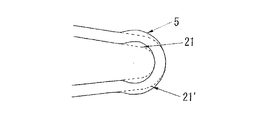
本発明のステントにおいて、ステントを構成するセルの略円弧部5を構成する弧の頂部の曲率半径が、セル2、2’の二つの略直線部の円弧側端部において形成される接線円21、21′の曲率半径の1.1~1.5倍の範囲内、好ましくは1.2~1.4の範囲内にある(図13参照)。このことによって、曲げ負荷により略円弧部の頂部に発生する最大応力のレベルが低下し、繰り返し曲げ負荷に対する耐久性が向上すると共に、拡張時に応力・歪が均一に分散されるため拡張均一性が良くなり、標準拡張圧力が従来ステントより低くなって、拡張操作の安全率が向上することとなる。曲率半径の1.1倍未満では、略円弧部の頂部に発生する最大応力のレベルを低下させることが困難であり、また、曲率半径の1.5倍を超えると、セルの略直線部と略円弧部との境界において応力が発生するようになり、耐久性向上効果が得られなくなる。また、1.5倍を超えると弧の頂部が大きくなりすぎて、ステントをクリンピングする時、円弧部同士が干渉することがあるので好ましくない。セル2,2’は、ステントの拡張後において中心軸C1に対し鈍角になるほうが、ステントの放射支持力が大きくなる。拡張後のセルの二つの略直線部が形成する角度θは120°に近づくほどステントの放射支持力が大きくなる。すなわちステントの設計においては、少なくともφ2.5mmに拡張したときにおいて、セルの拡張後の角度θは、少なくとも50°以上に設計するのが好ましい。 (General arc shape of the cell)
In the stent of the present invention, the radius of curvature of the top of the arc constituting the substantially
本発明においてステントのサイズ(ステントの非拡張時の長さ、非拡張時の直径)には、特に制約はなく、従来から使用されているステントと同じでよく、非拡張時の長さは、9~40mm程度、非拡張時の直径が0.8~2mm程度であることが好ましい。ステントの1つの環状ユニットの長さは、0.5~3.0mm程度が好ましい。1つの連結部の長さ(非連結部のセルとセル間の軸方向の隙間の長さ)は、0.05~1mm程度が好ましく、より好ましくは、0.1~0.3mmである。
また、セル2,2’の周方向の配置数は、4個以上が好ましい。さらに拡張後の径としてφ3.0mm以上となる場合においては6個以上、通常6~12個配置するのが好ましい。また環状ユニット3,3’は両方の環状ユニットを合わせてステント軸方向においては6個以上、通常6~12個配置するのが好ましい。更にステント軸方向においては10mm当り3個以上、通常4~8個配置し、ステント拡張の目標径(規格径、例えばφ3.0、φ4.0)となった時点において、例えば先に述べたようにセルの拡張後の角度θが、少なくとも50°以上、通常60°~120°に設計するのがよい。目標径において120°を超えるよう設計することは、ステントの放射支持力には有効であるが、略円弧部5の変形量が大きくなり問題が出る。また拡張に伴うステントの全長短縮(フォーショートニング)が大きくなり、ステント留置時の位置決めが困難となる等の問題が起り、好ましくない。 (Stent dimension)
In the present invention, the size of the stent (the length when the stent is not expanded, the diameter when the stent is not expanded) is not particularly limited, and may be the same as a conventionally used stent. Preferably, the diameter is about 9 to 40 mm, and the diameter when not expanded is about 0.8 to 2 mm. The length of one annular unit of the stent is preferably about 0.5 to 3.0 mm. The length of one connecting part (the length of the gap in the axial direction between cells in the non-connecting part) is preferably about 0.05 to 1 mm, more preferably 0.1 to 0.3 mm.
Further, the number of
また、本発明のステントは、生体内で分解可能な金属(生分解性金属)で製造されていてもよい。生分解性金属としては、純マグネシウム、マグネシウム合金、純鉄、鉄合金などが挙げられる。マグネシウム合金としては、マグネシウムを主成分とし、Zr、Y、Ti、Ta、Nd、Nb、Zn、Ca、Al、Li、およびMnからなる生体適合性元素群から選択される少なくとも1つの元素を含有するものが好ましい。例えば、マグネシウムが50~98%、リチウム(Li)が0~40%、鉄が0~5%、その他の金属または希土類元素(セリウム、ランタン、ネオジム、プラセオジム等)が0~5%であるものを挙げることができる。鉄合金としては、鉄を主成分として、Mn、Co、Ni、Cr、Cu、Cd、Pb、Sn、Th、Zr、Ag、Au、Pd、Pt、Re、Si、Ca、Li、Al、Zn、Fe、C、Sからなる生体適合性元素群から選択される少なくとも1つの元素を含むものが好ましい。例えば88-99.8%の鉄、0.1-7%のクロムおよび0-3.5%のニッケル並びに5%より少ない他の金属を含むものが例示される。
さらにまた、本発明のステントは、ポリ乳酸、ポリグリコール酸、ポリ(乳酸―グリコール酸)、ポリ(乳酸―ε―カプロラクトン)、ポリ(グリコール酸―ε―カプロラクトン)など生分解性ポリマー、ポリ(コハク酸ブチレン)などの生分解性高靭性ポリマーがポリ乳酸などの生分解性マトリックスポリマー内に分散した複合生分解性ポリマーで製造されてもよい。これらの生分解性ポリマーは、延伸・配向されていてもよい。さらに、生体内で分解可能な金属の上に、生分解性ポリマーが被覆されていてもよい。 The stent of the present invention is manufactured from a metal pipe made of stainless steel such as SUS316, shape memory alloy such as Ni—Ti alloy, Cu—Al—Mn alloy, titanium alloy, tantalum alloy, cobalt chromium alloy or the like.
In addition, the stent of the present invention may be manufactured from a metal (biodegradable metal) that can be decomposed in vivo. Examples of the biodegradable metal include pure magnesium, magnesium alloy, pure iron, and iron alloy. The magnesium alloy contains magnesium as a main component and contains at least one element selected from a biocompatible element group consisting of Zr, Y, Ti, Ta, Nd, Nb, Zn, Ca, Al, Li, and Mn. Those that do are preferred. For example, magnesium is 50 to 98%, lithium (Li) is 0 to 40%, iron is 0 to 5%, and other metals or rare earth elements (cerium, lanthanum, neodymium, praseodymium, etc.) are 0 to 5% Can be mentioned. The iron alloy includes iron as a main component, Mn, Co, Ni, Cr, Cu, Cd, Pb, Sn, Th, Zr, Ag, Au, Pd, Pt, Re, Si, Ca, Li, Al, Zn It preferably contains at least one element selected from the group of biocompatible elements consisting of Fe, C and S. Examples include those containing 88-99.8% iron, 0.1-7% chromium and 0-3.5% nickel and less than 5% other metals.
Furthermore, the stent of the present invention comprises a biodegradable polymer such as polylactic acid, polyglycolic acid, poly (lactic acid-glycolic acid), poly (lactic acid-ε-caprolactone), poly (glycolic acid-ε-caprolactone), poly ( A biodegradable high toughness polymer such as butylene succinate) may be made of a composite biodegradable polymer dispersed in a biodegradable matrix polymer such as polylactic acid. These biodegradable polymers may be stretched and oriented. Furthermore, a biodegradable polymer may be coated on a metal that can be decomposed in vivo.
径3.0mmステントを内径3.0mm、外径4.0mmのシリコンチューブ内に挿入し、生理食塩水を通して、ステントの内径を3mmまでバルーンで拡張したときの拡張圧力を測定した。 (Measurement of expansion pressure)
A 3.0 mm diameter stent was inserted into a silicon tube having an inner diameter of 3.0 mm and an outer diameter of 4.0 mm, and the expansion pressure was measured when the inner diameter of the stent was expanded to 3 mm with a balloon through physiological saline.
図11に示すようにチューブの両端を固定し、シリコンチューブの左端をステージに固定して、右端をカムに固定し、モーターの回転でカムを作動させ、カムをステント中心部が側方2.0mm屈曲するように往復させて、シリコンチューブの中心部を曲げ、チューブ内に挿入したステントの中心を繰り返して折り曲げるようにして破断するまでの耐久時間を測定した。 (Measurement of bending endurance time)
As shown in Fig. 11, fix the both ends of the tube, fix the left end of the silicon tube to the stage, fix the right end to the cam, operate the cam by rotating the motor, the center of the stent is 2.0mm on the side By reciprocating so as to be bent, the center part of the silicon tube was bent, and the endurance time until it was broken by repeatedly bending the center of the stent inserted into the tube was measured.
4点曲げ法で曲げ強度を測定し、この値により柔軟性を評価した。 (Evaluation of flexibility)
The bending strength was measured by a four-point bending method, and the flexibility was evaluated based on this value.
ステントを、内径3.0mm、外径4.0mmのシリコンチューブ内に挿入し、生理食塩水を通して、ステントの内径を3mmまでに拡張した。拡張後のステントの長さを測定し、拡張前のステントの長さに対する縮小率を算出して、フォーショートニング値とした。 (For shortening value measurement)
The stent was inserted into a silicon tube having an inner diameter of 3.0 mm and an outer diameter of 4.0 mm, and the inner diameter of the stent was expanded to 3 mm through physiological saline. The length of the stent after expansion was measured, and the reduction ratio with respect to the length of the stent before expansion was calculated to obtain a for shortening value.
ステントを、内径3.0mm、外径4.0mmのシリコンチューブ内に挿入し、生理食塩水を通して、バルーンによりステントの内径を3mmまでに拡張した。その後、バルーンを除去し、バルーン除去後のステントの内径を測定して下記の式(1)によりリコイル値を算出した。 (Calculation of recoil value)
The stent was inserted into a silicon tube having an inner diameter of 3.0 mm and an outer diameter of 4.0 mm, and the inner diameter of the stent was expanded to 3 mm with a balloon through physiological saline. Thereafter, the balloon was removed, the inner diameter of the stent after the balloon was removed, and the recoil value was calculated by the following equation (1).

ステントをクリンパによる縮径から血管内へのバルーン拡張による留置までの一連の過程で、ステント各部に発生する歪みを材料強度面から評価するため、コンピュータシミュレーションにより分析した。ステント有限要素モデルを構築し、適切な材質特性及び特徴を入力し、ステントを外径1.0mmまで縮径してから内径3.0mmまで拡張して、血管に留置し、一連の過程での発生する最大歪みを算出した。 (Maximum strain measurement)
In order to evaluate the strain generated in each part of the stent from the viewpoint of material strength in the series of processes from the diameter reduction by the crimper to the placement by balloon expansion into the blood vessel, it was analyzed by computer simulation. Build a stent finite element model, input appropriate material properties and characteristics, expand the stent to an inner diameter of 3.0 mm after reducing the stent diameter to 1.0 mm, place it in the blood vessel, and generate in a series of processes Maximum strain was calculated.
図1に示した実施例1ステントの連結部および非連結部のすべてのセルの略円弧部5を構成する弧の頂部の曲率半径は、略直線部2の接線円弧の曲率半径R0.15μに対し、1.3倍の曲率半径R0.20μ(図2)である。
(非連結部におけるセルの長さ:1.2mm、連結部における1つのセルの長さ:1.3mm、1つの環状ユニットにおけるセルの数:6 ) Example 1
The curvature radius of the top of the arc constituting the substantially
(The length of the cell in the unconnected portion: 1.2 mm, the length of one cell in the connected portion: 1.3 mm, the number of cells in one annular unit: 6)
図7に示した比較例1の従来ステント(全リンクステント)は、複数の第一のセル11を周方向に連結した第一のセル群からなる第一の環状ユニット12と該第一のセルと径方向から見て対称形状の複数の第二のセル11’ 群からなる第二の環状ユニット12’を交互に配置し、相対するセル同士を全て連結して略管状体を形成している。前記隣り合う環状ユニット12、12’同士はすべて連結部14により連結され、該管状体の内部より円周方向に伸張可能であって、複数のセル11を周方向に連結し、これらをステント15の中心軸C1を取り囲むように複数配列して構成されている。
(1つのセルの長さ:1.2mm、連結部の長さ:0.6mm、1つの環状ユニットにおけるセルの数:6 ) (Comparative Example 1)
The conventional stent (all link stent) of Comparative Example 1 shown in FIG. 7 includes a first
(Length of one cell: 1.2 mm, length of connecting portion: 0.6 mm, number of cells in one annular unit: 6)
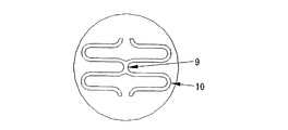
図3に示した比較例2のステントのセル円弧部10を構成する弧の頂部の曲率半径はR0.15μ(図4)である。
(1つのセルの長さ:1.2mm、連結部における1つのセルの長さ:1.3mm、1つの環状ユニットにおけるセルの数:6 ) (Comparative Example 2)
The radius of curvature of the top of the arc constituting the
(Length of one cell: 1.2 mm, length of one cell in the connecting portion: 1.3 mm, number of cells in one annular unit: 6)
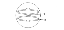
図5に示した比較例3のステントのセル円弧部10を構成する弧の頂部の曲率半径はR0.20μ(図6)である。
(非連結部における1つのセルの長さ:1.2mm、連結部における1つのセルの長さ:1.3mm、1つの環状ユニットにおけるセルの数:6 ) (Comparative Example 3)
The radius of curvature of the top of the arc constituting the
(Length of one cell in the unconnected portion: 1.2 mm, length of one cell in the connected portion: 1.3 mm, number of cells in one annular unit: 6)
図14に示した比較例4のステントは、図7に示した比較例1の従来ステントにおいて、環状ユニット12,12'の相対するセル11、11’が略S字状の連結部14で連結された全リンク型の連結部の代わりに、1つおきに連結部を設けた部分リンク型である。 (Comparative Example 4)
The stent of Comparative Example 4 shown in FIG. 14 is the same as the conventional stent of Comparative Example 1 shown in FIG. 7, but the

2,2’セル
3,3’,3’’,3’’’ 環状ユニット
4 連結部
5 セル円弧部
6 従来ステント(比較例2、3)
7,7’セル
8,8’環状ユニット
9 連結部
10 円弧部
11,11’セル
12,12’環状ユニット
13 屈曲部
14 連結部
15 従来ステント(比較例1)
16,16’セル
17 連結部
18,18’セル
19 溶接部
20,20’中心円弧
21,21’接線円
22 最大応力発生点
a、a’ 連結部の列
C1・・・ステントの中心軸 DESCRIPTION OF SYMBOLS 1
7, 7 '
16, 16 '
C1 ・ ・ ・ Stent central axis
Claims (11)
- 略直線部と略円弧部とを備える、軸方向に沿って一端側に開口した略U字型形状を有するセルが複数連結して形成された環状ユニットが軸方向に複数配列して連結部で連結されることにより管状体を形成し、前記管状体は、その内部より半径方向に伸張可能なステントであって、
複数の第一のセルを周方向に連結した第一のセル群からなる第一の環状ユニットと、複数の第二のセルを周方向に連結した第二のセル群からなる第二の環状ユニットがステントの中心軸を取り囲むように交互に配置され、前記第一セルと前記第二セルの形状は前記連結部を中心にして、ステントの軸方向に対称であり、前記隣接する第一及び第二の環状ユニットの複数の相対するセル同士の中の一部のセル同士のみが連結部で連結され、前記連結部は、相対するセルの前記略円弧部同士が接続して形成されたステントにおいて、
前記ステントを構成する実質的に全てのセルにおける、セルの略円弧部を形成する弧の頂部の曲率半径は、前記セルの略直線部の円弧側端部において形成される接線円の曲率半径の1.1~1.5倍の範囲内にあることを特徴とするステント。 A plurality of annular units formed by connecting a plurality of cells each having a substantially U-shape that opens to one end along the axial direction, each having a substantially straight portion and a substantially arc portion, are arranged in the axial direction. Are connected to form a tubular body, the tubular body being a radially expandable stent from the inside thereof,
A first annular unit consisting of a first cell group connecting a plurality of first cells in the circumferential direction, and a second annular unit consisting of a second cell group connecting a plurality of second cells in the circumferential direction. Are alternately arranged so as to surround the central axis of the stent, and the shapes of the first cell and the second cell are symmetrical with respect to the axial direction of the stent around the connecting portion, and the adjacent first and second cells In the stent formed by connecting only a part of the cells in the plurality of opposing cells of the second annular unit by a connecting portion, and the connecting portion is formed by connecting the substantially arc portions of the opposing cells. ,
The curvature radius of the top of the arc forming the substantially arc portion of the cell in substantially all cells constituting the stent is the radius of curvature of the tangential circle formed at the arc-side end of the substantially straight portion of the cell. A stent characterized by being in the range of 1.1 to 1.5 times. - 請求項1において、セルの前記略円弧部を構成する弧の頂部の曲率半径が、セルの前記略直線部の略円弧側端部において形成される接線円の曲率半径の1.2~1.4倍であるステント。 2. The curvature radius of the top of the arc constituting the substantially arc portion of the cell according to claim 1, wherein the radius of curvature of a tangent circle formed at the end of the approximately arc side of the substantially linear portion of the cell is 1.2 to 1. Stent that is 4 times.
- 請求項1において、前記連結部で連結されているセル同士の双方のセルの略直線部の長さが、同じ長さで、非連結部のセルの略直線部の長さよりも、若干長くなっているステント。 In Claim 1, the length of the substantially straight line portion of both cells connected by the connecting portion is the same length, and is slightly longer than the length of the substantially straight line portion of the non-connected portion cell. Stent.
- 請求項3において、前記連結部で連結されているセルの略直線部が、非連結部のセルの略直線部より10~25%長いステント。 4. The stent according to claim 3, wherein the substantially straight part of the cells connected by the connecting part is 10 to 25% longer than the substantially straight part of the cells of the non-connected part.
- 請求項1において、それぞれの前記環状ユニットは6~10個のセルから構成されており、その中の1~3個のセルが、相対するセルとの間に連結部を形成しているステント。 2. The stent according to claim 1, wherein each of the annular units is composed of 6 to 10 cells, and 1 to 3 cells among them form a connecting portion with the opposing cells.
- 請求項1において、前記連結部は、相対するセルの前記略円弧部同士が直接接続して形成されているステント。 2. The stent according to claim 1, wherein the connecting portion is formed by directly connecting the substantially arc portions of opposing cells.
- 請求項6において、前記連結部は、相対するセルの略円弧部同士の中心円弧の頂点を互いに共有しているステント。 7. The stent according to claim 6, wherein the connecting portion shares the vertexes of the central arcs of the substantially arc portions of the opposing cells.
- 請求項1において、前記セル及び前記連結部の幅及び厚みが、それぞれ一定であるステント。 2. The stent according to claim 1, wherein the cell and the connecting portion have a constant width and thickness.
- 請求項1において、コバルトクロム合金またはステンレス鋼で形成されたステント。 The stent according to claim 1, which is made of a cobalt chromium alloy or stainless steel.
- 請求項1において、生分解性金属または生分解性ポリマーからなる材料で形成されたステント。 The stent according to claim 1, wherein the stent is made of a material made of a biodegradable metal or a biodegradable polymer.
- 請求項10において、生分解性金属が、純マグネシウム、マグネシウム合金、純鉄、または鉄合金であるステント。 The stent according to claim 10, wherein the biodegradable metal is pure magnesium, magnesium alloy, pure iron, or iron alloy.
Priority Applications (5)
| Application Number | Priority Date | Filing Date | Title |
|---|---|---|---|
| CN2010800412209A CN102497838A (en) | 2009-09-17 | 2010-09-16 | Stent |
| US13/395,581 US8882827B2 (en) | 2009-09-17 | 2010-09-16 | Stent |
| JP2011531975A JP5684133B2 (en) | 2009-09-17 | 2010-09-16 | Stent |
| EP10817267.7A EP2478876A4 (en) | 2009-09-17 | 2010-09-16 | Stent |
| IN2511DEN2012 IN2012DN02511A (en) | 2009-09-17 | 2010-09-16 |
Applications Claiming Priority (2)
| Application Number | Priority Date | Filing Date | Title |
|---|---|---|---|
| JP2009-215464 | 2009-09-17 | ||
| JP2009215464 | 2009-09-17 |
Publications (1)
| Publication Number | Publication Date |
|---|---|
| WO2011034154A1 true WO2011034154A1 (en) | 2011-03-24 |
Family
ID=43758754
Family Applications (1)
| Application Number | Title | Priority Date | Filing Date |
|---|---|---|---|
| PCT/JP2010/066100 WO2011034154A1 (en) | 2009-09-17 | 2010-09-16 | Stent |
Country Status (6)
| Country | Link |
|---|---|
| US (1) | US8882827B2 (en) |
| EP (1) | EP2478876A4 (en) |
| JP (1) | JP5684133B2 (en) |
| CN (1) | CN102497838A (en) |
| IN (1) | IN2012DN02511A (en) |
| WO (1) | WO2011034154A1 (en) |
Cited By (1)
| Publication number | Priority date | Publication date | Assignee | Title |
|---|---|---|---|---|
| CN102813566A (en) * | 2012-04-24 | 2012-12-12 | 冯海全 | Coronary stent |
Families Citing this family (9)
| Publication number | Priority date | Publication date | Assignee | Title |
|---|---|---|---|---|
| CN102753119A (en) * | 2009-10-30 | 2012-10-24 | 科迪斯公司 | Intraluminal device with improved flexibility and durability |
| US20110282428A1 (en) * | 2010-05-13 | 2011-11-17 | Boston Scientific Scimed, Inc. | Biodegradable composite stent |
| NZ701992A (en) | 2012-05-14 | 2016-03-31 | Bard Inc C R | Uniformly expandable stent |
| USD723165S1 (en) | 2013-03-12 | 2015-02-24 | C. R. Bard, Inc. | Stent |
| CN103462734A (en) * | 2013-09-18 | 2013-12-25 | 深圳市金瑞凯利生物科技有限公司 | Coronary vessel stent and manufacturing method thereof |
| DE102014016588A1 (en) | 2014-11-11 | 2016-05-12 | medicut Stent Technology GmbH | stent graft |
| AU2016361380B2 (en) * | 2015-11-26 | 2021-04-08 | Japan Medical Device Technology Co., Ltd. | Bioabsorbable stent |
| CN105902331A (en) * | 2016-04-08 | 2016-08-31 | 南京永明医疗器械有限公司 | Intravascular stent and preparation method thereof |
| WO2018143115A1 (en) | 2017-02-01 | 2018-08-09 | 学校法人加計学園岡山理科大学 | Bioabsorbable stent |
Citations (6)
| Publication number | Priority date | Publication date | Assignee | Title |
|---|---|---|---|---|
| JPH03145720A (en) | 1989-10-31 | 1991-06-20 | Oki Electric Ind Co Ltd | Compound semiconductor growth method and silicon substrate to be used thereon |
| JP3654627B2 (en) | 2000-04-20 | 2005-06-02 | 川澄化学工業株式会社 | Stent |
| JP3663192B2 (en) | 2001-10-16 | 2005-06-22 | 川澄化学工業株式会社 | Stent |
| JP3145720U (en) * | 2008-08-06 | 2008-10-16 | 株式会社日本ステントテクノロジー | Stent |
| WO2008126894A1 (en) * | 2007-04-12 | 2008-10-23 | Kaneka Corporation | Stent |
| JP2009082245A (en) * | 2007-09-27 | 2009-04-23 | Terumo Corp | In-vivo indwelling stent and living organ dilator |
Family Cites Families (11)
| Publication number | Priority date | Publication date | Assignee | Title |
|---|---|---|---|---|
| DE29708879U1 (en) * | 1997-05-20 | 1997-07-31 | Jomed Implantate Gmbh | Coronary stent |
| JP3605388B2 (en) | 2001-10-16 | 2004-12-22 | 川澄化学工業株式会社 | Stent |
| AU2003228890A1 (en) * | 2002-05-08 | 2003-11-11 | Abbott Laboratories | Endoprosthesis having foot extensions |
| US20060121080A1 (en) * | 2002-11-13 | 2006-06-08 | Lye Whye K | Medical devices having nanoporous layers and methods for making the same |
| JP4797473B2 (en) * | 2005-07-11 | 2011-10-19 | ニプロ株式会社 | Flexible stent with excellent expandability |
| PT1752113E (en) * | 2005-08-10 | 2009-03-18 | Axetis Ag | Tubular stent with laterally overlapping arcs |
| US8388673B2 (en) * | 2008-05-02 | 2013-03-05 | Abbott Cardiovascular Systems Inc. | Polymeric stent |
| EP2186492B1 (en) | 2007-09-27 | 2012-08-15 | Terumo Kabushiki Kaisha | Stent and living organ dilator |
| EP3505142B1 (en) * | 2007-10-19 | 2020-10-28 | CeloNova Biosciences, Inc. | Implantable and lumen-supporting stents |
| CN101357089A (en) * | 2008-09-12 | 2009-02-04 | 西北有色金属研究院 | Production method of biology degradable magnesium alloy vascular inner rack |
| CA2757627C (en) * | 2009-04-10 | 2014-10-28 | Ev3 Inc. | Implants having high fatigue resistance, implant delivery systems, and methods of use |
-
2010
- 2010-09-16 CN CN2010800412209A patent/CN102497838A/en active Pending
- 2010-09-16 WO PCT/JP2010/066100 patent/WO2011034154A1/en active Application Filing
- 2010-09-16 EP EP10817267.7A patent/EP2478876A4/en not_active Withdrawn
- 2010-09-16 JP JP2011531975A patent/JP5684133B2/en not_active Expired - Fee Related
- 2010-09-16 IN IN2511DEN2012 patent/IN2012DN02511A/en unknown
- 2010-09-16 US US13/395,581 patent/US8882827B2/en not_active Expired - Fee Related
Patent Citations (6)
| Publication number | Priority date | Publication date | Assignee | Title |
|---|---|---|---|---|
| JPH03145720A (en) | 1989-10-31 | 1991-06-20 | Oki Electric Ind Co Ltd | Compound semiconductor growth method and silicon substrate to be used thereon |
| JP3654627B2 (en) | 2000-04-20 | 2005-06-02 | 川澄化学工業株式会社 | Stent |
| JP3663192B2 (en) | 2001-10-16 | 2005-06-22 | 川澄化学工業株式会社 | Stent |
| WO2008126894A1 (en) * | 2007-04-12 | 2008-10-23 | Kaneka Corporation | Stent |
| JP2009082245A (en) * | 2007-09-27 | 2009-04-23 | Terumo Corp | In-vivo indwelling stent and living organ dilator |
| JP3145720U (en) * | 2008-08-06 | 2008-10-16 | 株式会社日本ステントテクノロジー | Stent |
Non-Patent Citations (1)
| Title |
|---|
| See also references of EP2478876A4 * |
Cited By (1)
| Publication number | Priority date | Publication date | Assignee | Title |
|---|---|---|---|---|
| CN102813566A (en) * | 2012-04-24 | 2012-12-12 | 冯海全 | Coronary stent |
Also Published As
| Publication number | Publication date |
|---|---|
| EP2478876A1 (en) | 2012-07-25 |
| US20120172974A1 (en) | 2012-07-05 |
| JP5684133B2 (en) | 2015-03-11 |
| US8882827B2 (en) | 2014-11-11 |
| CN102497838A (en) | 2012-06-13 |
| IN2012DN02511A (en) | 2015-08-28 |
| EP2478876A4 (en) | 2014-07-16 |
| JPWO2011034154A1 (en) | 2013-02-14 |
Similar Documents
| Publication | Publication Date | Title |
|---|---|---|
| JP5684133B2 (en) | Stent | |
| JP4871692B2 (en) | In vivo indwelling stent and biological organ dilator | |
| AU2006338440B2 (en) | Endoluminal prosthesis | |
| JP5243577B2 (en) | In-vivo stent | |
| US8449596B2 (en) | Stent and stent delivery device | |
| JP2007144108A (en) | In vivo indwelling stent | |
| JP5573911B2 (en) | Indwelling stent | |
| US7651524B2 (en) | Flexible stent | |
| JP4846414B2 (en) | In vivo indwelling stent and biological organ dilator | |
| US20130096669A1 (en) | Partially annealed stent | |
| JP3145720U (en) | Stent | |
| JP3146103U (en) | Stent | |
| WO2018143115A1 (en) | Bioabsorbable stent | |
| JP4654361B2 (en) | Stent | |
| JP5267457B2 (en) | Stent | |
| JP4835113B2 (en) | Stent | |
| US8157858B2 (en) | Stent and stent delivery device | |
| JP2016059506A (en) | Stent which can be properly placed to lesioned part | |
| JP2016059504A (en) | Stent improved in flexibility | |
| JP2016059505A (en) | Stent having improved extension uniformity | |
| JP2017094017A (en) | Stent | |
| JP5612985B2 (en) | Stent, stent system including the same, and stent manufacturing method | |
| EP4212133A1 (en) | Stent and method for producing stent | |
| JP2012034896A (en) | In vivo indwelling stent and biological organ dilator implement | |
| RU2393820C2 (en) | Intraluminal prosthesis |
Legal Events
| Date | Code | Title | Description |
|---|---|---|---|
| WWE | Wipo information: entry into national phase |
Ref document number: 201080041220.9 Country of ref document: CN |
|
| 121 | Ep: the epo has been informed by wipo that ep was designated in this application |
Ref document number: 10817267 Country of ref document: EP Kind code of ref document: A1 |
|
| WWE | Wipo information: entry into national phase |
Ref document number: 2011531975 Country of ref document: JP Ref document number: 13395581 Country of ref document: US Ref document number: 2010817267 Country of ref document: EP |
|
| NENP | Non-entry into the national phase |
Ref country code: DE |
|
| WWE | Wipo information: entry into national phase |
Ref document number: 2511/DELNP/2012 Country of ref document: IN |