WO2011024291A1 - Display device - Google Patents
Display device Download PDFInfo
- Publication number
- WO2011024291A1 WO2011024291A1 PCT/JP2009/065063 JP2009065063W WO2011024291A1 WO 2011024291 A1 WO2011024291 A1 WO 2011024291A1 JP 2009065063 W JP2009065063 W JP 2009065063W WO 2011024291 A1 WO2011024291 A1 WO 2011024291A1
- Authority
- WO
- WIPO (PCT)
- Prior art keywords
- light
- light guide
- display
- display light
- image display
- Prior art date
Links
Images


Classifications
-
- G—PHYSICS
- G02—OPTICS
- G02B—OPTICAL ELEMENTS, SYSTEMS OR APPARATUS
- G02B27/00—Optical systems or apparatus not provided for by any of the groups G02B1/00 - G02B26/00, G02B30/00
- G02B27/01—Head-up displays
- G02B27/0101—Head-up displays characterised by optical features
-
- G—PHYSICS
- G02—OPTICS
- G02B—OPTICAL ELEMENTS, SYSTEMS OR APPARATUS
- G02B27/00—Optical systems or apparatus not provided for by any of the groups G02B1/00 - G02B26/00, G02B30/00
- G02B27/01—Head-up displays
- G02B27/0101—Head-up displays characterised by optical features
- G02B2027/0123—Head-up displays characterised by optical features comprising devices increasing the field of view
- G02B2027/0125—Field-of-view increase by wavefront division
-
- G—PHYSICS
- G02—OPTICS
- G02B—OPTICAL ELEMENTS, SYSTEMS OR APPARATUS
- G02B6/00—Light guides; Structural details of arrangements comprising light guides and other optical elements, e.g. couplings
Definitions
- the present invention relates to an information device that can be used in an environment other than a desktop, such as a wearable computer that is worn on the body via a waist belt or jewelry, or a communication device such as a mobile phone that can be carried in a knapsack or pocket.
- the present invention relates to a display device suitable for a monitor.
- FIG. 5 is an external view showing a conventional eyeglass-type display (display device) mounted on the observer's head.
- FIG. 6 is an optical path diagram illustrating a schematic configuration of a plane of a conventional glasses-type display worn on the observer's head, and
- FIG. 7 illustrates a schematic configuration of a side surface of the glasses-type display illustrated in FIG. 8 is an optical path diagram, and
- FIG. 8 is an optical path diagram showing a schematic configuration of another side surface of the eyeglass-type display shown in FIG.
- the glasses-type display 101 has an appearance similar to that of glasses, and guides the image display light L to the observer's eye E while reflecting the image display light L from the unit U and the unit U. It includes a first light guide 104 and a second light guide 5 that are substrates, and a frame portion F to which the unit portion U, the first light guide 104, and the second light guide 5 are attached (see, for example, Patent Document 1).
- the glasses-type display 101 is for the right eye, and defines an XYZ coordinate system having an origin at the center of the right eye E in a state of looking far away. The Z direction is in front of the observer, the Y direction is below the observer, and the X direction is to the left of the observer.
- the unit portion U has an emission mechanism having a transmissive liquid crystal display (display element) 2 that forms an image to be a display region (Z 1 ⁇ Y 1 ) on a surface perpendicular to the emission direction and emits image display light L.
- the emission mechanism S includes a light source (not shown) and a transmissive liquid crystal display 2.
- the transmissive liquid crystal display 2 forms an image to be a display region (Z 1 ⁇ Y 1 ) on a surface perpendicular to the emission direction, and emits the image display light L.
- Optics 103 image display light for all the range of the display area (Z 1 ⁇ Y 1) and the first optical element 103a which reflects and transmits the image display light L, the entire range of the display area (Z 1 ⁇ Y 1) And a second optical element 103b that reflects L. Accordingly, the optical system 103 forms a virtual image of the observation target while reflecting and transmitting the image display light L in the entire display area (Z 1 ⁇ Y 1 ).
- the first light guide 104 has a rectangular shape made of polycarbonate (refractive index ng), a planar total reflection surface 141 formed at one end and disposed in front of the emission mechanism S (Z direction), and the other end. And a side surface formed between the total reflection surface 141 and the emission surface 142 by an interface with air, and the emission surface 142 arranged behind the total reflection surface 51 of the second light guide 5 ( ⁇ Z direction).
- a group 143 is a rectangular shape made of polycarbonate (refractive index ng), a planar total reflection surface 141 formed at one end and disposed in front of the emission mechanism S (Z direction), and the other end. And a side surface formed between the total reflection surface 141 and the emission surface 142 by an interface with air, and the emission surface 142 arranged behind the total reflection surface 51 of the second light guide 5 ( ⁇ Z direction).
- the side group 143 has a quadrangular shape when viewed from the X direction (first setting direction), the first surface 143a, the second surface 143b facing the first surface 143a in the Z direction, the third surface 143c, It has the surface 143c and the 4th surface 143d which opposes in a Y direction. At this time, the distance between the third surface 143c and the fourth surface 143d is H ′.
- the total reflection surface 141 has a planar shape, is arranged so as to be perpendicular to the third surface 143c and the fourth surface 143d, and not parallel to the first surface 143a and the second surface 143b.
- the emission surface 142 includes five planar emission surfaces, and in order in the X direction (first setting direction), the first emission surface 142a, the second emission surface 142b,..., The fifth emission surface. It is arranged to be 142e. Further, each of the emission surfaces 142a to 142e is disposed so as to be perpendicular to the third surface 143c and the fourth surface 143d and not parallel to the first surface 143a and the second surface 143b. .
- Each of the exit surfaces 142a to 142e is a beam splitter surface that reflects 19% of the incident image display light L and transmits 81% of the image display light L.
- the second light guide 5 has a flat plate shape made of polycarbonate (refractive index ng), is formed at one end, and is arranged in front of the first light guide 104 (in the Z direction), and the other end. And an exit surface 52 disposed in front of the observer's eye E (Z direction) and a side group 53 formed between the total reflection surface 51 and the exit surface 52 by an interface with air. .
- the side group 53 has a quadrangular shape when viewed from the Y direction (second setting direction), the first surface 53a, the second surface 53b facing the first surface 53a in the Z direction, the third surface 53c, and the third surface. It has the surface 53c and the 4th surface 53d which opposes in a X direction.
- Total reflection surface 51 has a planar shape, is disposed so as to be perpendicular to third surface 53c and fourth surface 53d, and not parallel to first surface 53a and second surface 53b.
- the emission surface 52 is composed of five planar emission surfaces, and in order in the Y direction (second setting direction), the first emission surface 52a, the second emission surface 52b,..., The fifth emission surface. 52e. Further, each of the emission surfaces 52a to 52e is disposed so as to be perpendicular to the third surface 53c and the fourth surface 53d and not parallel to the first surface 52a and the second surface 52b.
- Each of the exit surfaces 52a to 52e is a beam splitter surface that reflects 19% of the incident image display light L and transmits 81% of the image display light L.
- the total reflection surface 141 of the first light guide 104 reflects the image display light L in the display area (Z 1 ⁇ Y 1 ) from the optical system 103 in the substantially X direction.
- the two surfaces of the first surface 143a and the second surface 143b guide the image display light L in the display region (Z 1 ⁇ Y 1 ) to the first emission surface 142a while alternately reflecting the image display light L a plurality of times. Therefore, the first emission surface 142a reflects 19% of the incident light beam of the image display light L and transmits 81% of the light beam of the image display light L.
- the light flux of the image display light that is 19.0% of the light flux of the image display light L is guided toward a part of the total reflection surface 51 of the second light guide 5.
- the image display light L transmitted through the first emission surface 142a reaches the second emission surface 142b. Therefore, the second exit surface 142b reflects 19% of the incident light flux of the image display light L and transmits 81% of the light flux of the image display light L. That is, the light flux of the image display light that is 15.4% of the light flux of the image display light L is guided toward the other part of the total reflection surface 51 of the second light guide 5.
- each of the exit surfaces 142a to 142e reflects 19% of the incident light flux of the image display light L and transmits 81% of the light flux of the image display light L, thereby setting the light flux of the image display light L.
- the luminous flux of the image display light as a ratio is guided toward the total reflection surface 51 of the second light guide 5.
- the total reflection surface 51 of the second light guide 5 reflects the image display light L in the display area (Z 1 ⁇ Y 1 ) from the first light guide 104 in the substantially Y direction.
- the two surfaces of the first surface 53a and the second surface 53b guide the image display light L in the display region (Z 1 ⁇ Y 1 ) to the first emission surface 52a while alternately reflecting the image display light L a plurality of times. Therefore, the first emission surface 52a reflects 19% of the incident image display light L and transmits 81% of the image display light L. That is, the light flux of the image display light that is the set ratio of the light flux of the image display light L is guided toward the observer's eye E.
- the image display light L transmitted through the first emission surface 52a reaches the second emission surface 52b. Therefore, the second emission surface 52b reflects 19% of the incident light beam of the image display light L and transmits 81% of the light beam of the image display light L. That is, the light flux of the image display light that is the set ratio of the light flux of the image display light L is guided toward the observer's eye E. As described above, each of the exit surfaces 52a to 52e reflects 19% of the incident light beam of the image display light L and transmits 81% of the light beam of the image display light L, thereby setting the light beam of the image display light L. The luminous flux of the image display light as a ratio is guided toward the observer's eye E.
- an object of the present invention is to provide a display device that can reduce the size and weight of the first light guide and the optical system.
- the display device of the present invention made to solve the above problems includes an emission mechanism having a display element for emitting display light, an optical system, a first light guide, and a second light guide, and the optical system.
- the second surface facing the first surface, the exit surface arranged in front of the observer's eye, and the total reflection surface, and the total reflection surface reflects the display light from the first light guide
- a display device that guides display light from the exit surface to the observer's eyes while reflecting the display light in the second setting direction on the two surfaces, the first surface and the second surface.
- the first light guide includes a first surface and a second surface facing the first surface; A third surface, a fourth surface facing the third surface, an emission surface, and a total reflection surface; after reflecting display light from the emission mechanism on the total reflection surface, the first surface
- the display light is guided to the exit surface while reflecting the display light in the first setting direction on the four surfaces of the second surface, the third surface, and the fourth surface, and the display light is guided from the exit surface to the total reflection surface of the second light guide I try to guide you.
- the “first setting direction” is an arbitrary direction predetermined by a designer or the like, and is, for example, the left side of the observer or the right side of the observer.
- the “second setting direction” is an arbitrary direction predetermined by a designer or the like, and is, for example, below the observer or above the observer.
- the first light guide reflects the display light from the emission mechanism on the total reflection surface, and then the four surfaces of the first surface, the second surface, the third surface, and the fourth surface. Since the display light is guided to the exit surface while reflecting the display light in the first setting direction, the size of the optical system for guiding the display light to the first light guide, and the third and fourth surfaces of the first light guide itself The distance between them can be reduced.
- the first light guide and the optical system can be reduced in size and weight.
- the exit surface of the first light guide has a plurality of planar shapes capable of reflecting the set ratio of the incident display light beam and transmitting the set ratio of the display light beam.
- a beam splitter surface or a total reflection surface, and the beam splitter surfaces are arranged in order in the first setting direction and are parallel to each other, and the first surface, the second surface, and the third surface.
- the exit surface of the second light guide can reflect the set ratio of the incident display light beam and transmit the set ratio of the display light beam.
- a plurality of planar beam splitter surfaces or total reflection surfaces each of the beam splitter surfaces being arranged in order in the second setting direction and parallel to each other, and the first surface and the second surface It may not be parallel and perpendicular to the.
- the “set ratio” is an arbitrary ratio predetermined by a designer or the like. For example, 19% of the incident light flux of the display light is reflected and 81% of the light flux of the display light is transmitted. To be decided.
- first setting direction and the second setting direction may be perpendicular to each other.
- FIG. 1 is an optical path diagram showing a schematic configuration of a plane of a glasses-type display (display device) according to an embodiment of the present invention
- FIG. 2 is an optical path showing a schematic configuration of a side surface of the glasses-type display shown in FIG.
- FIG. 3 is an optical path diagram showing a schematic configuration of another side surface of the eyeglass-type display shown in FIG.
- the glasses-type display 1 includes a unit unit U that emits image display light L, a first light guide 4 that is a substrate that guides the image display light L from the unit unit U to the eyes E of the observer while reflecting the image display light L, and the first light guide 4.
- the unit portion U has an emission mechanism having a transmissive liquid crystal display (display element) 2 that forms an image to be a display region (Z 1 ⁇ Y 1 ) on a surface perpendicular to the emission direction and emits image display light L.
- S and an optical system 3 that forms a virtual image of an observation object.
- Optical system 3 the image display light for all the range of the display area (Z 1 ⁇ Y 1) and the first optical element 3a for reflecting and transmitting the image display light L, the entire range of the display area (Z 1 ⁇ Y 1)
- a second optical element 3b that reflects L. Accordingly, the optical system 3 forms a virtual image of the observation target while reflecting and transmitting the image display light L in the entire display area (Z 1 ⁇ Y 1 ).
- the image display light L of the entire range (Z 1 ⁇ Y 1 ) of the display area is converted into the first surface 43a, the second surface 43b, the third surface 43c, and the fourth surface of the first light guide 4. Since the light is reflected by four surfaces 43d, the size of the optical system 3 in the Y direction is small.
- the first light guide 4 has a square columnar shape made of polycarbonate (refractive index ng), is formed at one end and is disposed in front of the emission mechanism S (in the Z direction).
- the guide 5 includes an emission surface 42 disposed behind the total reflection surface 51 ( ⁇ Z direction) and a side group 43 formed between the total reflection surface 41 and the emission surface 42 by an interface with air.
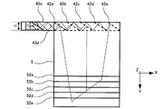
- FIG. 4 is a perspective view showing a part of the first light guide.
- the side group 43 has a quadrangular shape when viewed from the X direction (first setting direction), the first surface 43a, the second surface 43b facing the first surface 43a in the Z direction, the third surface 43c, and the third surface.
- the distance between the third surface 43c and the fourth surface 43d is H. That is, the distance H between the third surface 43c and the fourth surface 43d is smaller than the distance H ′ between the third surface 143c and the fourth surface 143d.
- the total reflection surface 41 has a planar shape and is arranged so as not to be perpendicular to and parallel to the first surface 43a, the second surface 43b, the third surface 43c, and the fourth surface 43d.
- the exit surface 42 includes five planar exit surfaces, and in order in the X direction (first setting direction), the first exit surface 42a, the second exit surface 42b,..., The fifth exit surface. 42e.
- each of the emission surfaces 42a to 42e is arranged not to be perpendicular to and parallel to the first surface 43a, the second surface 43b, the third surface 43c, and the fourth surface 43d.
- each of the emission surfaces 42 a to 42 e is disposed so as to be parallel to the total reflection surface 41.
- Each of the exit surfaces 42a to 42e is a beam splitter surface that reflects 19% of the incident image display light L and transmits 81% of the image display light L.
- the total reflection surface 41 of the first light guide 4 reflects the image display light L in the display region (Z 1 ⁇ Y 1 ) in the substantially X direction.
- the image display light L in the display area (Z 1 ⁇ Y 1 ) is reflected by the first surface 43a, reflected by the third surface 43c, reflected by the second surface 43b, and reflected by the fourth surface 43d.
- the light is guided to the first emission surface 42a while being reflected a plurality of times. Therefore, the first emission surface 42a reflects 19% of the incident light flux of the image display light L and transmits 81% of the light flux of the image display light L.
- the light flux of the image display light that is 19.0% of the light flux of the image display light L is guided toward a part of the total reflection surface 51 of the second light guide 5. Further, the image display light L transmitted through the first emission surface 42a reaches the second emission surface 42b. Therefore, the second exit surface 42b reflects 19% of the incident light flux of the image display light L and transmits 81% of the light flux of the image display light L. That is, the light flux of the image display light that is 15.4% of the light flux of the image display light L is guided toward the other part of the total reflection surface 51 of the second light guide 5.
- each of the exit surfaces 42a to 42e reflects 19% of the incident light flux of the image display light L and transmits 81% of the light flux of the image display light L, thereby setting the light flux of the image display light L.
- the luminous flux of the image display light as a ratio is guided toward the total reflection surface 51 of the second light guide 5.
- the total reflection surface 51 of the second light guide 5 reflects the image display light L in the display area (Z 1 ⁇ Y 1 ) from the first light guide 4 in the substantially Y direction.
- the two surfaces of the first surface 53a and the second surface 53b guide the image display light L in the display region (Z 1 ⁇ Y 1 ) to the first emission surface 52a while alternately reflecting the image display light L a plurality of times. Therefore, the first emission surface 52a reflects 19% of the incident image display light L and transmits 81% of the image display light L. That is, the light flux of the image display light that is the set ratio of the light flux of the image display light L is guided toward the observer's eye E.
- the image display light L transmitted through the first emission surface 52a reaches the second emission surface 52b. Therefore, the second emission surface 52b reflects 19% of the incident light beam of the image display light L and transmits 81% of the light beam of the image display light L. That is, the light flux of the image display light that is the set ratio of the light flux of the image display light L is guided toward the observer's eye E. In this way, each of the emission surfaces 52a to 52e reflects the image display light L, thereby guiding the light beam of the image display light, which is a set ratio of the light beam of the image display light L, toward the eye E of the observer.
- the first light guide 4 and the optical system 3 can be reduced in size and weight.
- the above-described glasses-type display is mounted on the body of an observer's head and arms, a helmet or glasses worn on the body via a headset, a belt, a band, a clip, or the like, or a mobile phone or a wristwatch. It may be attached to various portable devices such as or may be used while being held in the hand. Moreover, it is not limited to a form such as a head-mounted display attached to the observer, but may be a form such as a head-up display installed in front of the observer.
- the emission mechanism may display a virtual image of an observation object in color with a light source that emits three-color light of R (red), G (green), and B (blue) in a time-sharing manner. Further, the image display light may be guided to both eyes of the observer.
- the configuration in which the X direction and the first setting direction coincide with each other is shown, but the X direction and the first setting direction may not coincide with each other. Can be in any one direction.
- the configuration in which the Y direction and the second setting direction match is shown, the Y direction and the second setting direction may not match, and the second setting direction may be any one direction. be able to.
- the material for forming the first light guide and the second light guide include polycarbonate, polymethacrylic acid (PMMA), cycloolefin, and glass material.
- the first light guide 4 has five emission surfaces 42a to 42e and the second light guide 5 has five emission surfaces 52a to 52e.
- One light guide may have four exit surfaces, and the second light guide may have six exit surfaces, and the number of exit surfaces can be any number.
- the exit surfaces 42a to 42e of the first light guide 4 and the exit surfaces 52a to 52e of the second light guide 5 reflect 19% of the light flux of the incident image display light L and Although the configuration is such that it is a beam splitter surface that transmits 81% of the luminous flux of the display light L, the exit surface of the first light guide and the exit surface of the second light guide reflect different ratios, respectively.
- a configuration in which the beam splitter surface and the total reflection surface transmit different ratios may be used.
- the exit surface 42a has a reflectance of 20%, a transmittance of 80%
- the exit surface 42b has a reflectance of 25%, a transmittance of 75%
- the exit surface 42c has a reflectance of 33%, a transmittance of 67%
- the exit surface 42d has a reflectance of 50%, a transmittance of 50%
- the exit surface 42e is a total reflection surface (reflectance 100%)
- the emission light from each emission surface may be made uniform by 20% of the light flux of the image display light L.
- the refractive index ng of polycarbonate which is the material of the first light guide 4 is between the second surface 43 b of the first light guide 4 and the first surface 53 a of the second light guide 5.
- the second light guide 5 may be bonded via a medium (for example, fluoride) having a refractive index ng and a lower refractive index ng ′ of polycarbonate which is a material of the second light guide 5.
- the present invention can be used for information devices used in environments other than the desktop.
Landscapes
- Physics & Mathematics (AREA)
- General Physics & Mathematics (AREA)
- Optics & Photonics (AREA)
Abstract
A display device is provided with: a light outputting mechanism (S) having a display element (2) which outputs display light; a first light guide (4); and a second light guide (5). The first light guide (4) guides display light to the second light guide (5), and the second light guide (5) guides display light to a light outputting surface (52) while reflecting display light in a second set direction by means of a first surface (53a) and a second surface (53b), and the second light guide guides display light to the eye (E) of an observer from the light outputting surface (52). In the first light guide (4), display light outputted from the light outputting mechanism (S) is reflected by a total reflection surface (41), then, is guided to a light outputting surface (42), while reflecting display light in a first set direction by means of four surfaces, i.e. a first surface (43a), a second surface (43b), a third surface (43c) and a fourth surface (43d), and display light is guided to the second light guide (5) from the light outputting surface (42).
Description
本発明は、腰のベルトや装身具等を介して身体に纏うウエアラブルコンピュータや、ナップサックやポケットに入れて携帯できる携帯電話器等の通信機器のような、卓上以外の環境で利用可能な情報機器のためのモニタに適した表示装置に関する。
The present invention relates to an information device that can be used in an environment other than a desktop, such as a wearable computer that is worn on the body via a waist belt or jewelry, or a communication device such as a mobile phone that can be carried in a knapsack or pocket. The present invention relates to a display device suitable for a monitor.
身体に纏う形態の情報機器用の表示装置としては、眼鏡型の形態が主流となりつつある。図5は、観察者の頭部に装着される従来の眼鏡型ディスプレイ(表示装置)を示す外観図である。また、図6は、観察者の頭部に装着される従来の眼鏡型ディスプレイの平面の概略構成を示す光路図であり、図7は、図6に示す眼鏡型ディスプレイの側面の概略構成を示す光路図であり、図8は、図6に示す眼鏡型ディスプレイの他の側面の概略構成を示す光路図である。
眼鏡型ディスプレイ101は、眼鏡と似た外観をしており、画像表示光Lを出射するユニット部Uと、ユニット部Uからの画像表示光Lを内部で反射させながら観察者の眼Eに導く基板である第一ライトガイド104及び第二ライトガイド5と、ユニット部Uと第一ライトガイド104と第二ライトガイド5とが取り付けられるフレーム部Fとを備える(例えば、特許文献1参照)。
なお、眼鏡型ディスプレイ101は右眼用であり、遠方を見ている状態の右眼Eの中心に原点を有したXYZ座標系を定義する。Z方向は観察者の前方であり、Y方向は観察者の下方であり、X方向は観察者の左方である。 As display devices for information devices that are worn on the body, eyeglass-type forms are becoming mainstream. FIG. 5 is an external view showing a conventional eyeglass-type display (display device) mounted on the observer's head. FIG. 6 is an optical path diagram illustrating a schematic configuration of a plane of a conventional glasses-type display worn on the observer's head, and FIG. 7 illustrates a schematic configuration of a side surface of the glasses-type display illustrated in FIG. 8 is an optical path diagram, and FIG. 8 is an optical path diagram showing a schematic configuration of another side surface of the eyeglass-type display shown in FIG.
The glasses-type display 101 has an appearance similar to that of glasses, and guides the image display light L to the observer's eye E while reflecting the image display light L from the unit U and the unit U. It includes a first light guide 104 and a second light guide 5 that are substrates, and a frame portion F to which the unit portion U, the first light guide 104, and the second light guide 5 are attached (see, for example, Patent Document 1).
The glasses-type display 101 is for the right eye, and defines an XYZ coordinate system having an origin at the center of the right eye E in a state of looking far away. The Z direction is in front of the observer, the Y direction is below the observer, and the X direction is to the left of the observer.
眼鏡型ディスプレイ101は、眼鏡と似た外観をしており、画像表示光Lを出射するユニット部Uと、ユニット部Uからの画像表示光Lを内部で反射させながら観察者の眼Eに導く基板である第一ライトガイド104及び第二ライトガイド5と、ユニット部Uと第一ライトガイド104と第二ライトガイド5とが取り付けられるフレーム部Fとを備える(例えば、特許文献1参照)。
なお、眼鏡型ディスプレイ101は右眼用であり、遠方を見ている状態の右眼Eの中心に原点を有したXYZ座標系を定義する。Z方向は観察者の前方であり、Y方向は観察者の下方であり、X方向は観察者の左方である。 As display devices for information devices that are worn on the body, eyeglass-type forms are becoming mainstream. FIG. 5 is an external view showing a conventional eyeglass-type display (display device) mounted on the observer's head. FIG. 6 is an optical path diagram illustrating a schematic configuration of a plane of a conventional glasses-type display worn on the observer's head, and FIG. 7 illustrates a schematic configuration of a side surface of the glasses-type display illustrated in FIG. 8 is an optical path diagram, and FIG. 8 is an optical path diagram showing a schematic configuration of another side surface of the eyeglass-type display shown in FIG.
The glasses-
The glasses-
ユニット部Uは、出射方向に垂直である面に表示領域(Z1×Y1)となる画像を形成して画像表示光Lを出射する透過型液晶表示器(表示素子)2を有する出射機構Sと、観察対象の虚像を形成する光学系103とを備える。
出射機構Sは、光源(図示せず)と、透過型液晶表示器2とを備える。透過型液晶表示器2は、出射方向に垂直である面に表示領域(Z1×Y1)となる画像を形成し、その画像表示光Lを出射する。
光学系103は、表示領域の全範囲(Z1×Y1)の画像表示光Lを反射及び透過させる第一光学素子103aと、表示領域の全範囲(Z1×Y1)の画像表示光Lを反射させる第二光学素子103bとを有する。これにより、光学系103は、表示領域の全範囲(Z1×Y1)の画像表示光Lを反射及び透過させながら、観察対象の虚像を形成する。 The unit portion U has an emission mechanism having a transmissive liquid crystal display (display element) 2 that forms an image to be a display region (Z 1 × Y 1 ) on a surface perpendicular to the emission direction and emits image display light L. S and an optical system 103 that forms a virtual image to be observed.
The emission mechanism S includes a light source (not shown) and a transmissiveliquid crystal display 2. The transmissive liquid crystal display 2 forms an image to be a display region (Z 1 × Y 1 ) on a surface perpendicular to the emission direction, and emits the image display light L.
Optics 103, image display light for all the range of the display area (Z 1 × Y 1) and the firstoptical element 103a which reflects and transmits the image display light L, the entire range of the display area (Z 1 × Y 1) And a second optical element 103b that reflects L. Accordingly, the optical system 103 forms a virtual image of the observation target while reflecting and transmitting the image display light L in the entire display area (Z 1 × Y 1 ).
出射機構Sは、光源(図示せず)と、透過型液晶表示器2とを備える。透過型液晶表示器2は、出射方向に垂直である面に表示領域(Z1×Y1)となる画像を形成し、その画像表示光Lを出射する。
光学系103は、表示領域の全範囲(Z1×Y1)の画像表示光Lを反射及び透過させる第一光学素子103aと、表示領域の全範囲(Z1×Y1)の画像表示光Lを反射させる第二光学素子103bとを有する。これにより、光学系103は、表示領域の全範囲(Z1×Y1)の画像表示光Lを反射及び透過させながら、観察対象の虚像を形成する。 The unit portion U has an emission mechanism having a transmissive liquid crystal display (display element) 2 that forms an image to be a display region (Z 1 × Y 1 ) on a surface perpendicular to the emission direction and emits image display light L. S and an optical system 103 that forms a virtual image to be observed.
The emission mechanism S includes a light source (not shown) and a transmissive
Optics 103, image display light for all the range of the display area (Z 1 × Y 1) and the first
第一ライトガイド104は、ポリカーボネイト製(屈折率ng)の四角注形状となり、一端部に形成され出射機構Sの前方(Z方向)に配置される平面形状の全反射面141と、他端部に形成され第二ライトガイド5の全反射面51の後方(-Z方向)に配置される出射面142と、空気との界面によって全反射面141と出射面142との間に形成される側面群143とを有する。
側面群143は、X方向(第一設定方向)から見ると四角形状となり、第一面143aと、第一面143aとZ方向で対向する第二面143bと、第三面143cと、第三面143cとY方向で対向する第四面143dとを有する。このとき、第三面143cと第四面143dとの間の距離は、H’となる。 Thefirst light guide 104 has a rectangular shape made of polycarbonate (refractive index ng), a planar total reflection surface 141 formed at one end and disposed in front of the emission mechanism S (Z direction), and the other end. And a side surface formed between the total reflection surface 141 and the emission surface 142 by an interface with air, and the emission surface 142 arranged behind the total reflection surface 51 of the second light guide 5 (−Z direction). A group 143.
The side group 143 has a quadrangular shape when viewed from the X direction (first setting direction), thefirst surface 143a, the second surface 143b facing the first surface 143a in the Z direction, the third surface 143c, It has the surface 143c and the 4th surface 143d which opposes in a Y direction. At this time, the distance between the third surface 143c and the fourth surface 143d is H ′.
側面群143は、X方向(第一設定方向)から見ると四角形状となり、第一面143aと、第一面143aとZ方向で対向する第二面143bと、第三面143cと、第三面143cとY方向で対向する第四面143dとを有する。このとき、第三面143cと第四面143dとの間の距離は、H’となる。 The
The side group 143 has a quadrangular shape when viewed from the X direction (first setting direction), the
全反射面141は、平面形状であり、第三面143cと第四面143dに対して垂直であり、かつ、第一面143aと第二面143bに対して平行でないように配置されている。
出射面142は、5枚の平面形状の出射面からなり、X方向(第一設定方向)において順番に、第一出射面142aと、第二出射面142bと、・・・、第五出射面142eとなるように配置されている。
さらに、各出射面142a~142eは、第三面143cと第四面143dとに対して垂直であり、かつ、第一面143aと第二面143bとに対して平行でないように配置されている。
そして、各出射面142a~142eは、入射した画像表示光Lの光束の19%を反射するとともに、画像表示光Lの光束の81%を透過することが可能なビームスプリッタ面となっている。 Thetotal reflection surface 141 has a planar shape, is arranged so as to be perpendicular to the third surface 143c and the fourth surface 143d, and not parallel to the first surface 143a and the second surface 143b.
The emission surface 142 includes five planar emission surfaces, and in order in the X direction (first setting direction), thefirst emission surface 142a, the second emission surface 142b,..., The fifth emission surface. It is arranged to be 142e.
Further, each of theemission surfaces 142a to 142e is disposed so as to be perpendicular to the third surface 143c and the fourth surface 143d and not parallel to the first surface 143a and the second surface 143b. .
Each of theexit surfaces 142a to 142e is a beam splitter surface that reflects 19% of the incident image display light L and transmits 81% of the image display light L.
出射面142は、5枚の平面形状の出射面からなり、X方向(第一設定方向)において順番に、第一出射面142aと、第二出射面142bと、・・・、第五出射面142eとなるように配置されている。
さらに、各出射面142a~142eは、第三面143cと第四面143dとに対して垂直であり、かつ、第一面143aと第二面143bとに対して平行でないように配置されている。
そして、各出射面142a~142eは、入射した画像表示光Lの光束の19%を反射するとともに、画像表示光Lの光束の81%を透過することが可能なビームスプリッタ面となっている。 The
The emission surface 142 includes five planar emission surfaces, and in order in the X direction (first setting direction), the
Further, each of the
Each of the
第二ライトガイド5は、ポリカーボネイト製(屈折率ng)の平板形状となり、一端部に形成され第一ライトガイド104の前方(Z方向)に配置される平面形状の全反射面51と、他端部に形成され観察者の眼Eの前方(Z方向)に配置される出射面52と、空気との界面によって全反射面51と出射面52との間に形成される側面群53とを有する。
側面群53は、Y方向(第二設定方向)から見ると四角形状となり、第一面53aと、第一面53aとZ方向で対向する第二面53bと、第三面53cと、第三面53cとX方向で対向する第四面53dとを有する。 Thesecond light guide 5 has a flat plate shape made of polycarbonate (refractive index ng), is formed at one end, and is arranged in front of the first light guide 104 (in the Z direction), and the other end. And an exit surface 52 disposed in front of the observer's eye E (Z direction) and a side group 53 formed between the total reflection surface 51 and the exit surface 52 by an interface with air. .
The side group 53 has a quadrangular shape when viewed from the Y direction (second setting direction), thefirst surface 53a, the second surface 53b facing the first surface 53a in the Z direction, the third surface 53c, and the third surface. It has the surface 53c and the 4th surface 53d which opposes in a X direction.
側面群53は、Y方向(第二設定方向)から見ると四角形状となり、第一面53aと、第一面53aとZ方向で対向する第二面53bと、第三面53cと、第三面53cとX方向で対向する第四面53dとを有する。 The
The side group 53 has a quadrangular shape when viewed from the Y direction (second setting direction), the
全反射面51は、平面形状であり、第三面53cと第四面53dとに対して垂直であり、かつ、第一面53aと第二面53bとに対して平行でないように配置されている。
出射面52は、5枚の平面形状の出射面からなり、Y方向(第二設定方向)において順番に、第一出射面52aと、第二出射面52bと、・・・、第五出射面52eとなるように配置されている。
さらに、各出射面52a~52eは、第三面53cと第四面53dに対して垂直であり、かつ、第一面52aと第二面52bに対して平行でないように配置されている。
そして、各出射面52a~52eは、入射した画像表示光Lの光束の19%を反射するとともに、画像表示光Lの光束の81%を透過することが可能なビームスプリッタ面となっている。Total reflection surface 51 has a planar shape, is disposed so as to be perpendicular to third surface 53c and fourth surface 53d, and not parallel to first surface 53a and second surface 53b. Yes.
The emission surface 52 is composed of five planar emission surfaces, and in order in the Y direction (second setting direction), thefirst emission surface 52a, the second emission surface 52b,..., The fifth emission surface. 52e.
Further, each of theemission surfaces 52a to 52e is disposed so as to be perpendicular to the third surface 53c and the fourth surface 53d and not parallel to the first surface 52a and the second surface 52b.
Each of theexit surfaces 52a to 52e is a beam splitter surface that reflects 19% of the incident image display light L and transmits 81% of the image display light L.
出射面52は、5枚の平面形状の出射面からなり、Y方向(第二設定方向)において順番に、第一出射面52aと、第二出射面52bと、・・・、第五出射面52eとなるように配置されている。
さらに、各出射面52a~52eは、第三面53cと第四面53dに対して垂直であり、かつ、第一面52aと第二面52bに対して平行でないように配置されている。
そして、各出射面52a~52eは、入射した画像表示光Lの光束の19%を反射するとともに、画像表示光Lの光束の81%を透過することが可能なビームスプリッタ面となっている。
The emission surface 52 is composed of five planar emission surfaces, and in order in the Y direction (second setting direction), the
Further, each of the
Each of the
このような眼鏡型ディスプレイ101において、第一ライトガイド104の全反射面141は、光学系103からの表示領域(Z1×Y1)の画像表示光Lを略X方向へと反射する。そして、第一面143aと第二面143bとの2面は、表示領域(Z1×Y1)の画像表示光Lを交互に複数回反射しながら、第一出射面142aに導く。そこで、第一出射面142aは、入射した画像表示光Lの光束の19%を反射するとともに、画像表示光Lの光束の81%を透過する。つまり、画像表示光Lの光束の19.0%である画像表示光の光束を、第二ライトガイド5の全反射面51の一部分に向かって導く。
また、第一出射面142aを透過した画像表示光Lは、第二出射面142bに到達する。そこで、第二出射面142bは、入射した画像表示光Lの光束の19%を反射するとともに、画像表示光Lの光束の81%を透過する。つまり、画像表示光Lの光束の15.4%である画像表示光の光束を第二ライトガイド5の全反射面51の他の一部分に向かって導く。
このように各出射面142a~142eは、入射した画像表示光Lの光束の19%を反射するとともに、画像表示光Lの光束の81%を透過することにより、画像表示光Lの光束の設定割合である画像表示光の光束を第二ライトガイド5の全反射面51に向かって導く。 In such a glasses-type display 101, the total reflection surface 141 of the first light guide 104 reflects the image display light L in the display area (Z 1 × Y 1 ) from the optical system 103 in the substantially X direction. The two surfaces of the first surface 143a and the second surface 143b guide the image display light L in the display region (Z 1 × Y 1 ) to the first emission surface 142a while alternately reflecting the image display light L a plurality of times. Therefore, the first emission surface 142a reflects 19% of the incident light beam of the image display light L and transmits 81% of the light beam of the image display light L. That is, the light flux of the image display light that is 19.0% of the light flux of the image display light L is guided toward a part of the total reflection surface 51 of the second light guide 5.
Further, the image display light L transmitted through thefirst emission surface 142a reaches the second emission surface 142b. Therefore, the second exit surface 142b reflects 19% of the incident light flux of the image display light L and transmits 81% of the light flux of the image display light L. That is, the light flux of the image display light that is 15.4% of the light flux of the image display light L is guided toward the other part of the total reflection surface 51 of the second light guide 5.
In this way, each of theexit surfaces 142a to 142e reflects 19% of the incident light flux of the image display light L and transmits 81% of the light flux of the image display light L, thereby setting the light flux of the image display light L. The luminous flux of the image display light as a ratio is guided toward the total reflection surface 51 of the second light guide 5.
また、第一出射面142aを透過した画像表示光Lは、第二出射面142bに到達する。そこで、第二出射面142bは、入射した画像表示光Lの光束の19%を反射するとともに、画像表示光Lの光束の81%を透過する。つまり、画像表示光Lの光束の15.4%である画像表示光の光束を第二ライトガイド5の全反射面51の他の一部分に向かって導く。
このように各出射面142a~142eは、入射した画像表示光Lの光束の19%を反射するとともに、画像表示光Lの光束の81%を透過することにより、画像表示光Lの光束の設定割合である画像表示光の光束を第二ライトガイド5の全反射面51に向かって導く。 In such a glasses-
Further, the image display light L transmitted through the
In this way, each of the
そして、第二ライトガイド5の全反射面51は、第一ライトガイド104からの表示領域(Z1×Y1)の画像表示光Lを略Y方向へと反射する。そして、第一面53aと第二面53bとの2面は、表示領域(Z1×Y1)の画像表示光Lを交互に複数回反射しながら、第一出射面52aに導く。そこで、第一出射面52aは、入射した画像表示光Lの光束の19%を反射するとともに、画像表示光Lの光束の81%を透過する。つまり、画像表示光Lの光束の設定割合である画像表示光の光束を、観察者の眼Eに向かって導く。
また、第一出射面52aを透過した画像表示光Lは、第二出射面52bに到達する。そこで、第二出射面52bは、入射した画像表示光Lの光束の19%を反射するとともに、画像表示光Lの光束の81%を透過する。つまり、画像表示光Lの光束の設定割合である画像表示光の光束を観察者の眼Eに向かって導く。
このように各出射面52a~52eは、入射した画像表示光Lの光束の19%を反射するとともに、画像表示光Lの光束の81%を透過することにより、画像表示光Lの光束の設定割合である画像表示光の光束を観察者の眼Eに向かって導く。 Thetotal reflection surface 51 of the second light guide 5 reflects the image display light L in the display area (Z 1 × Y 1 ) from the first light guide 104 in the substantially Y direction. The two surfaces of the first surface 53a and the second surface 53b guide the image display light L in the display region (Z 1 × Y 1 ) to the first emission surface 52a while alternately reflecting the image display light L a plurality of times. Therefore, the first emission surface 52a reflects 19% of the incident image display light L and transmits 81% of the image display light L. That is, the light flux of the image display light that is the set ratio of the light flux of the image display light L is guided toward the observer's eye E.
Further, the image display light L transmitted through thefirst emission surface 52a reaches the second emission surface 52b. Therefore, the second emission surface 52b reflects 19% of the incident light beam of the image display light L and transmits 81% of the light beam of the image display light L. That is, the light flux of the image display light that is the set ratio of the light flux of the image display light L is guided toward the observer's eye E.
As described above, each of theexit surfaces 52a to 52e reflects 19% of the incident light beam of the image display light L and transmits 81% of the light beam of the image display light L, thereby setting the light beam of the image display light L. The luminous flux of the image display light as a ratio is guided toward the observer's eye E.
また、第一出射面52aを透過した画像表示光Lは、第二出射面52bに到達する。そこで、第二出射面52bは、入射した画像表示光Lの光束の19%を反射するとともに、画像表示光Lの光束の81%を透過する。つまり、画像表示光Lの光束の設定割合である画像表示光の光束を観察者の眼Eに向かって導く。
このように各出射面52a~52eは、入射した画像表示光Lの光束の19%を反射するとともに、画像表示光Lの光束の81%を透過することにより、画像表示光Lの光束の設定割合である画像表示光の光束を観察者の眼Eに向かって導く。 The
Further, the image display light L transmitted through the
As described above, each of the
しかしながら、このような眼鏡型ディスプレイ101では、第三面143cと第四面143dとは、画像表示光Lを一回も反射させずに、全反射面141から各出射面142a~142eまで導かないといけないので、光学系103のY方向の大きさや、第三面143cと第四面143dとの間の距離H’等を小さくすることができずに、第一ライトガイド104及び光学系103が大型化するとともに重くなるという問題点があった。
そこで、本発明は、第一ライトガイド及び光学系を小型化・軽量化することができる表示装置を提供することを目的とする。 However, in such a glasses-type display 101, the third surface 143c and the fourth surface 143d do not reflect the image display light L once, and do not guide from the total reflection surface 141 to the emission surfaces 142a to 142e. Since the size of the optical system 103 in the Y direction, the distance H ′ between the third surface 143c and the fourth surface 143d, etc. cannot be reduced, the first light guide 104 and the optical system 103 are There was a problem that it became heavier as it became larger.
Therefore, an object of the present invention is to provide a display device that can reduce the size and weight of the first light guide and the optical system.
そこで、本発明は、第一ライトガイド及び光学系を小型化・軽量化することができる表示装置を提供することを目的とする。 However, in such a glasses-
Therefore, an object of the present invention is to provide a display device that can reduce the size and weight of the first light guide and the optical system.
上記課題を解決するためになされた本発明の表示装置は、表示光を出射する表示素子を有する出射機構と、光学系と、第一ライトガイドと、第二ライトガイドとを備え、前記光学系は、前記出射機構からの表示光を第一ライトガイドに導き、前記第一ライトガイドは、前記光学系からの表示光を第二ライトガイドに導き、前記第二ライトガイドは、第一面と、当該第一面と対向する第二面と、観察者の眼の前方に配置される出射面と、全反射面とを有し、前記全反射面で第一ライトガイドからの表示光を反射させた後、前記第一面と第二面との2面で表示光を第二設定方向へと反射させながら出射面に導き、前記出射面から表示光を観察者の眼に導く表示装置であって、前記第一ライトガイドは、第一面と、当該第一面と対向する第二面と、第三面と、当該第三面と対向する第四面と、出射面と、全反射面とを有し、前記全反射面で出射機構からの表示光を反射させた後、前記第一面と第二面と第三面と第四面との4面で表示光を第一設定方向へと反射させながら出射面に導き、前記出射面から表示光を第二ライトガイドの全反射面に導くようにしている。
The display device of the present invention made to solve the above problems includes an emission mechanism having a display element for emitting display light, an optical system, a first light guide, and a second light guide, and the optical system. Guides display light from the emission mechanism to a first light guide, the first light guide guides display light from the optical system to a second light guide, and the second light guide The second surface facing the first surface, the exit surface arranged in front of the observer's eye, and the total reflection surface, and the total reflection surface reflects the display light from the first light guide A display device that guides display light from the exit surface to the observer's eyes while reflecting the display light in the second setting direction on the two surfaces, the first surface and the second surface. The first light guide includes a first surface and a second surface facing the first surface; A third surface, a fourth surface facing the third surface, an emission surface, and a total reflection surface; after reflecting display light from the emission mechanism on the total reflection surface, the first surface The display light is guided to the exit surface while reflecting the display light in the first setting direction on the four surfaces of the second surface, the third surface, and the fourth surface, and the display light is guided from the exit surface to the total reflection surface of the second light guide I try to guide you.
ここで、「第一設定方向」とは、設計者等によって予め決められた任意の一方向であり、例えば、観察者の左方や、観察者の右方等となる。
また、「第二設定方向」とは、設計者等によって予め決められた任意の一方向であり、例えば、観察者の下方や、観察者の上方等となる。
本発明の表示装置によれば、第一ライトガイドは、全反射面で出射機構からの表示光を反射させた後、第一面と第二面と第三面と第四面との4面で表示光を第一設定方向へと反射させながら出射面に導くので、第一ライトガイドに表示光を導くための光学系の大きさや、第一ライトガイド自体の第三面と第四面と間の距離等を小さくすることができる。 Here, the “first setting direction” is an arbitrary direction predetermined by a designer or the like, and is, for example, the left side of the observer or the right side of the observer.
The “second setting direction” is an arbitrary direction predetermined by a designer or the like, and is, for example, below the observer or above the observer.
According to the display device of the present invention, the first light guide reflects the display light from the emission mechanism on the total reflection surface, and then the four surfaces of the first surface, the second surface, the third surface, and the fourth surface. Since the display light is guided to the exit surface while reflecting the display light in the first setting direction, the size of the optical system for guiding the display light to the first light guide, and the third and fourth surfaces of the first light guide itself The distance between them can be reduced.
以上のように、本発明の表示装置によれば、第一ライトガイド及び光学系を小型化・軽量化することができる。
As described above, according to the display device of the present invention, the first light guide and the optical system can be reduced in size and weight.
(他の課題を解決するための手段および効果)
また、上記の発明において、前記第一ライトガイドの出射面は、入射した表示光の光束の設定割合を反射するとともに、表示光の光束の設定割合を透過することが可能な複数の平面形状のビームスプリッタ面又は全反射面であり、各ビームスプリッタ面は、前記第一設定方向において順番に配置されるとともに、お互いに平行であり、かつ、前記第一面と第二面と第三面と第四面とに対して平行及び垂直でなく、前記第二ライトガイドの出射面は、入射した表示光の光束の設定割合を反射するとともに、表示光の光束の設定割合を透過することが可能な複数の平面形状のビームスプリッタ面又は全反射面であり、各ビームスプリッタ面は、前記第二設定方向において順番に配置されるとともに、お互いに平行であり、かつ、前記第一面と第二面とに対して平行及び垂直でないようにしてもよい。
ここで、「設定割合」とは、設計者等によって予め決められた任意の割合であり、例えば、入射した表示光の光束の19%を反射するとともに、表示光の光束の81%を透過するように決められる。 (Means and effects for solving other problems)
In the above invention, the exit surface of the first light guide has a plurality of planar shapes capable of reflecting the set ratio of the incident display light beam and transmitting the set ratio of the display light beam. A beam splitter surface or a total reflection surface, and the beam splitter surfaces are arranged in order in the first setting direction and are parallel to each other, and the first surface, the second surface, and the third surface. Rather than being parallel and perpendicular to the fourth surface, the exit surface of the second light guide can reflect the set ratio of the incident display light beam and transmit the set ratio of the display light beam. A plurality of planar beam splitter surfaces or total reflection surfaces, each of the beam splitter surfaces being arranged in order in the second setting direction and parallel to each other, and the first surface and the second surface It may not be parallel and perpendicular to the.
Here, the “set ratio” is an arbitrary ratio predetermined by a designer or the like. For example, 19% of the incident light flux of the display light is reflected and 81% of the light flux of the display light is transmitted. To be decided.
さらに、上記の発明において、前記第一設定方向と第二設定方向とは垂直であるようにしてもよい。
Furthermore, in the above invention, the first setting direction and the second setting direction may be perpendicular to each other.
以下、本発明の実施形態について図面を用いて説明する。なお、本発明は、以下に説明するような実施形態に限定されるものではなく、本発明の趣旨を逸脱しない範囲で種々の態様が含まれることはいうまでもない。
Hereinafter, embodiments of the present invention will be described with reference to the drawings. Note that the present invention is not limited to the embodiments described below, and it is needless to say that various aspects are included without departing from the spirit of the present invention.
図1は、本発明の一実施形態である眼鏡型ディスプレイ(表示装置)の平面の概略構成を示す光路図であり、図2は、図1に示す眼鏡型ディスプレイの側面の概略構成を示す光路図であり、図3は、図1に示す眼鏡型ディスプレイの他の側面の概略構成を示す光路図である。なお、上述した眼鏡型ディスプレイ101と同様のものについては、同じ符号を付している。
眼鏡型ディスプレイ1は、画像表示光Lを出射するユニット部Uと、ユニット部Uからの画像表示光Lを内部で反射させながら観察者の眼Eに導く基板である第一ライトガイド4及び第二ライトガイド5と、ユニット部Uと第一ライトガイド4と第二ライトガイド5とが取り付けられるフレーム部Fとを備える。 FIG. 1 is an optical path diagram showing a schematic configuration of a plane of a glasses-type display (display device) according to an embodiment of the present invention, and FIG. 2 is an optical path showing a schematic configuration of a side surface of the glasses-type display shown in FIG. FIG. 3 is an optical path diagram showing a schematic configuration of another side surface of the eyeglass-type display shown in FIG. In addition, the same code | symbol is attached | subjected about the thing similar to thespectacles type display 101 mentioned above.
The glasses-type display 1 includes a unit unit U that emits image display light L, afirst light guide 4 that is a substrate that guides the image display light L from the unit unit U to the eyes E of the observer while reflecting the image display light L, and the first light guide 4. Two light guides 5, a unit portion U, a first light guide 4, and a frame portion F to which the second light guide 5 is attached.
眼鏡型ディスプレイ1は、画像表示光Lを出射するユニット部Uと、ユニット部Uからの画像表示光Lを内部で反射させながら観察者の眼Eに導く基板である第一ライトガイド4及び第二ライトガイド5と、ユニット部Uと第一ライトガイド4と第二ライトガイド5とが取り付けられるフレーム部Fとを備える。 FIG. 1 is an optical path diagram showing a schematic configuration of a plane of a glasses-type display (display device) according to an embodiment of the present invention, and FIG. 2 is an optical path showing a schematic configuration of a side surface of the glasses-type display shown in FIG. FIG. 3 is an optical path diagram showing a schematic configuration of another side surface of the eyeglass-type display shown in FIG. In addition, the same code | symbol is attached | subjected about the thing similar to the
The glasses-type display 1 includes a unit unit U that emits image display light L, a
ユニット部Uは、出射方向に垂直である面に表示領域(Z1×Y1)となる画像を形成して画像表示光Lを出射する透過型液晶表示器(表示素子)2を有する出射機構Sと、観察対象の虚像を形成する光学系3とを備える。
光学系3は、表示領域の全範囲(Z1×Y1)の画像表示光Lを反射及び透過させる第一光学素子3aと、表示領域の全範囲(Z1×Y1)の画像表示光Lを反射させる第二光学素子3bとを有する。これにより、光学系3は、表示領域の全範囲(Z1×Y1)の画像表示光Lを反射及び透過させながら、観察対象の虚像を形成する。
このとき、後述するが、表示領域の全範囲(Z1×Y1)の画像表示光Lを、第一ライトガイド4の第一面43aと第二面43bと第三面43cと第四面43dとの4面で反射させるので、光学系3のY方向の大きさは小さくなっている。 The unit portion U has an emission mechanism having a transmissive liquid crystal display (display element) 2 that forms an image to be a display region (Z 1 × Y 1 ) on a surface perpendicular to the emission direction and emits image display light L. S and an optical system 3 that forms a virtual image of an observation object.
Optical system 3, the image display light for all the range of the display area (Z 1 × Y 1) and the firstoptical element 3a for reflecting and transmitting the image display light L, the entire range of the display area (Z 1 × Y 1) And a second optical element 3b that reflects L. Accordingly, the optical system 3 forms a virtual image of the observation target while reflecting and transmitting the image display light L in the entire display area (Z 1 × Y 1 ).
At this time, as will be described later, the image display light L of the entire range (Z 1 × Y 1 ) of the display area is converted into thefirst surface 43a, the second surface 43b, the third surface 43c, and the fourth surface of the first light guide 4. Since the light is reflected by four surfaces 43d, the size of the optical system 3 in the Y direction is small.
光学系3は、表示領域の全範囲(Z1×Y1)の画像表示光Lを反射及び透過させる第一光学素子3aと、表示領域の全範囲(Z1×Y1)の画像表示光Lを反射させる第二光学素子3bとを有する。これにより、光学系3は、表示領域の全範囲(Z1×Y1)の画像表示光Lを反射及び透過させながら、観察対象の虚像を形成する。
このとき、後述するが、表示領域の全範囲(Z1×Y1)の画像表示光Lを、第一ライトガイド4の第一面43aと第二面43bと第三面43cと第四面43dとの4面で反射させるので、光学系3のY方向の大きさは小さくなっている。 The unit portion U has an emission mechanism having a transmissive liquid crystal display (display element) 2 that forms an image to be a display region (Z 1 × Y 1 ) on a surface perpendicular to the emission direction and emits image display light L. S and an optical system 3 that forms a virtual image of an observation object.
Optical system 3, the image display light for all the range of the display area (Z 1 × Y 1) and the first
At this time, as will be described later, the image display light L of the entire range (Z 1 × Y 1 ) of the display area is converted into the
第一ライトガイド4は、ポリカーボネイト製(屈折率ng)の四角柱形状となり、一端部に形成され出射機構Sの前方(Z方向)に配置される平面形状の全反射面41と、第二ライトガイド5の全反射面51の後方(-Z方向)に配置される出射面42と、空気との界面によって全反射面41と出射面42との間に形成される側面群43とを有する。なお、図4は、第一ライトガイドの一部を示す斜視図である。
側面群43は、X方向(第一設定方向)から見ると四角形状となり、第一面43aと、第一面43aとZ方向で対向する第二面43bと、第三面43cと、第三面43cとY方向(第二設定方向)で対向する第四面43dとを有する。このとき、第三面43cと第四面43dとの間の距離は、Hとなる。つまり、第三面43cと第四面43dとの間の距離Hは、第三面143cと第四面143dとの間の距離H’より小さくなっている。 Thefirst light guide 4 has a square columnar shape made of polycarbonate (refractive index ng), is formed at one end and is disposed in front of the emission mechanism S (in the Z direction). The guide 5 includes an emission surface 42 disposed behind the total reflection surface 51 (−Z direction) and a side group 43 formed between the total reflection surface 41 and the emission surface 42 by an interface with air. FIG. 4 is a perspective view showing a part of the first light guide.
The side group 43 has a quadrangular shape when viewed from the X direction (first setting direction), thefirst surface 43a, the second surface 43b facing the first surface 43a in the Z direction, the third surface 43c, and the third surface. It has the surface 43c and the 4th surface 43d which opposes in a Y direction (2nd setting direction). At this time, the distance between the third surface 43c and the fourth surface 43d is H. That is, the distance H between the third surface 43c and the fourth surface 43d is smaller than the distance H ′ between the third surface 143c and the fourth surface 143d.
側面群43は、X方向(第一設定方向)から見ると四角形状となり、第一面43aと、第一面43aとZ方向で対向する第二面43bと、第三面43cと、第三面43cとY方向(第二設定方向)で対向する第四面43dとを有する。このとき、第三面43cと第四面43dとの間の距離は、Hとなる。つまり、第三面43cと第四面43dとの間の距離Hは、第三面143cと第四面143dとの間の距離H’より小さくなっている。 The
The side group 43 has a quadrangular shape when viewed from the X direction (first setting direction), the
全反射面41は、平面形状であり、第一面43aと第二面43bと第三面43cと第四面43dとに対して垂直でなく、かつ、平行でないように配置されている。
出射面42は、5枚の平面形状の出射面からなり、X方向(第一設定方向)において順番に、第一出射面42aと、第二出射面42bと、・・・、第五出射面42eとなるように配置されている。
さらに、各出射面42a~42eは、第一面43aと第二面43bと第三面43cと第四面43dに対して垂直でなく、かつ、平行でないように配置されている。また、各出射面42a~42eは、全反射面41に対して平行であるように配置されている。
そして、各出射面42a~42eは、入射した画像表示光Lの光束の19%を反射するとともに、画像表示光Lの光束の81%を透過することが可能なビームスプリッタ面となっている。 Thetotal reflection surface 41 has a planar shape and is arranged so as not to be perpendicular to and parallel to the first surface 43a, the second surface 43b, the third surface 43c, and the fourth surface 43d.
The exit surface 42 includes five planar exit surfaces, and in order in the X direction (first setting direction), thefirst exit surface 42a, the second exit surface 42b,..., The fifth exit surface. 42e.
Further, each of the emission surfaces 42a to 42e is arranged not to be perpendicular to and parallel to thefirst surface 43a, the second surface 43b, the third surface 43c, and the fourth surface 43d. In addition, each of the emission surfaces 42 a to 42 e is disposed so as to be parallel to the total reflection surface 41.
Each of the exit surfaces 42a to 42e is a beam splitter surface that reflects 19% of the incident image display light L and transmits 81% of the image display light L.
出射面42は、5枚の平面形状の出射面からなり、X方向(第一設定方向)において順番に、第一出射面42aと、第二出射面42bと、・・・、第五出射面42eとなるように配置されている。
さらに、各出射面42a~42eは、第一面43aと第二面43bと第三面43cと第四面43dに対して垂直でなく、かつ、平行でないように配置されている。また、各出射面42a~42eは、全反射面41に対して平行であるように配置されている。
そして、各出射面42a~42eは、入射した画像表示光Lの光束の19%を反射するとともに、画像表示光Lの光束の81%を透過することが可能なビームスプリッタ面となっている。 The
The exit surface 42 includes five planar exit surfaces, and in order in the X direction (first setting direction), the
Further, each of the emission surfaces 42a to 42e is arranged not to be perpendicular to and parallel to the
Each of the exit surfaces 42a to 42e is a beam splitter surface that reflects 19% of the incident image display light L and transmits 81% of the image display light L.
このような眼鏡型ディスプレイ1において、第一ライトガイド4の全反射面41は、表示領域(Z1×Y1)の画像表示光Lを略X方向へと反射する。そして、例えば、表示領域(Z1×Y1)の画像表示光Lを、第一面43aが反射し、第三面43cが反射し、第二面43bが反射し、第四面43dが反射するように、複数回反射しながら、第一出射面42aに導く。そこで、第一出射面42aは、入射した画像表示光Lの光束の19%を反射するとともに、画像表示光Lの光束の81%を透過する。つまり、画像表示光Lの光束の19.0%である画像表示光の光束を、第二ライトガイド5の全反射面51の一部分に向かって導く。
また、第一出射面42aを透過した画像表示光Lは、第二出射面42bに到達する。そこで、第二出射面42bは、入射した画像表示光Lの光束の19%を反射するとともに、画像表示光Lの光束の81%を透過する。つまり、画像表示光Lの光束の15.4%である画像表示光の光束を、第二ライトガイド5の全反射面51の他の一部分に向かって導く。
このように各出射面42a~42eは、入射した画像表示光Lの光束の19%を反射するとともに、画像表示光Lの光束の81%を透過することにより、画像表示光Lの光束の設定割合である画像表示光の光束を、第二ライトガイド5の全反射面51に向かって導く。 In such a glasses-type display 1, thetotal reflection surface 41 of the first light guide 4 reflects the image display light L in the display region (Z 1 × Y 1 ) in the substantially X direction. For example, the image display light L in the display area (Z 1 × Y 1 ) is reflected by the first surface 43a, reflected by the third surface 43c, reflected by the second surface 43b, and reflected by the fourth surface 43d. As described above, the light is guided to the first emission surface 42a while being reflected a plurality of times. Therefore, the first emission surface 42a reflects 19% of the incident light flux of the image display light L and transmits 81% of the light flux of the image display light L. That is, the light flux of the image display light that is 19.0% of the light flux of the image display light L is guided toward a part of the total reflection surface 51 of the second light guide 5.
Further, the image display light L transmitted through thefirst emission surface 42a reaches the second emission surface 42b. Therefore, the second exit surface 42b reflects 19% of the incident light flux of the image display light L and transmits 81% of the light flux of the image display light L. That is, the light flux of the image display light that is 15.4% of the light flux of the image display light L is guided toward the other part of the total reflection surface 51 of the second light guide 5.
In this way, each of the exit surfaces 42a to 42e reflects 19% of the incident light flux of the image display light L and transmits 81% of the light flux of the image display light L, thereby setting the light flux of the image display light L. The luminous flux of the image display light as a ratio is guided toward thetotal reflection surface 51 of the second light guide 5.
また、第一出射面42aを透過した画像表示光Lは、第二出射面42bに到達する。そこで、第二出射面42bは、入射した画像表示光Lの光束の19%を反射するとともに、画像表示光Lの光束の81%を透過する。つまり、画像表示光Lの光束の15.4%である画像表示光の光束を、第二ライトガイド5の全反射面51の他の一部分に向かって導く。
このように各出射面42a~42eは、入射した画像表示光Lの光束の19%を反射するとともに、画像表示光Lの光束の81%を透過することにより、画像表示光Lの光束の設定割合である画像表示光の光束を、第二ライトガイド5の全反射面51に向かって導く。 In such a glasses-type display 1, the
Further, the image display light L transmitted through the
In this way, each of the exit surfaces 42a to 42e reflects 19% of the incident light flux of the image display light L and transmits 81% of the light flux of the image display light L, thereby setting the light flux of the image display light L. The luminous flux of the image display light as a ratio is guided toward the
そして、第二ライトガイド5の全反射面51は、第一ライトガイド4からの表示領域(Z1×Y1)の画像表示光Lを略Y方向へと反射する。そして、第一面53aと第二面53bとの2面は、表示領域(Z1×Y1)の画像表示光Lを交互に複数回反射しながら、第一出射面52aに導く。そこで、第一出射面52aは、入射した画像表示光Lの光束の19%を反射するとともに、画像表示光Lの光束の81%を透過する。つまり、画像表示光Lの光束の設定割合である画像表示光の光束を観察者の眼Eに向かって導く。
また、第一出射面52aを透過した画像表示光Lは、第二出射面52bに到達する。そこで、第二出射面52bは、入射した画像表示光Lの光束の19%を反射するとともに、画像表示光Lの光束の81%を透過する。つまり、画像表示光Lの光束の設定割合である画像表示光の光束を観察者の眼Eに向かって導く。
このように各出射面52a~52eが画像表示光Lを反射させることにより、画像表示光Lの光束の設定割合である画像表示光の光束を観察者の眼Eに向かって導く。 Thetotal reflection surface 51 of the second light guide 5 reflects the image display light L in the display area (Z 1 × Y 1 ) from the first light guide 4 in the substantially Y direction. The two surfaces of the first surface 53a and the second surface 53b guide the image display light L in the display region (Z 1 × Y 1 ) to the first emission surface 52a while alternately reflecting the image display light L a plurality of times. Therefore, the first emission surface 52a reflects 19% of the incident image display light L and transmits 81% of the image display light L. That is, the light flux of the image display light that is the set ratio of the light flux of the image display light L is guided toward the observer's eye E.
Further, the image display light L transmitted through thefirst emission surface 52a reaches the second emission surface 52b. Therefore, the second emission surface 52b reflects 19% of the incident light beam of the image display light L and transmits 81% of the light beam of the image display light L. That is, the light flux of the image display light that is the set ratio of the light flux of the image display light L is guided toward the observer's eye E.
In this way, each of the emission surfaces 52a to 52e reflects the image display light L, thereby guiding the light beam of the image display light, which is a set ratio of the light beam of the image display light L, toward the eye E of the observer.
また、第一出射面52aを透過した画像表示光Lは、第二出射面52bに到達する。そこで、第二出射面52bは、入射した画像表示光Lの光束の19%を反射するとともに、画像表示光Lの光束の81%を透過する。つまり、画像表示光Lの光束の設定割合である画像表示光の光束を観察者の眼Eに向かって導く。
このように各出射面52a~52eが画像表示光Lを反射させることにより、画像表示光Lの光束の設定割合である画像表示光の光束を観察者の眼Eに向かって導く。 The
Further, the image display light L transmitted through the
In this way, each of the emission surfaces 52a to 52e reflects the image display light L, thereby guiding the light beam of the image display light, which is a set ratio of the light beam of the image display light L, toward the eye E of the observer.
以上のように、眼鏡型ディスプレイ1によれば、第一ライトガイド4及び光学系3を小型化・軽量化することができる。
As described above, according to the glasses-type display 1, the first light guide 4 and the optical system 3 can be reduced in size and weight.
(他の実施形態)
上述した眼鏡型ディスプレイは、観察者の頭部や腕等の身体や、身体に装着されるヘルメットや眼鏡等に、ヘッドセット、ベルト、バンド、クリップ等を介して装着されたり、携帯電話や腕時計等の各種携帯機器に装着されたり、手に持った状態で使用されたりしてもよい。また、観察者に装着されるヘッドマウントディスプレイのような形態に限らず、観察者の前方に設置するヘッドアップディスプレイのような形態であってもよい。
上記出射機構は、R(赤)、G(緑)、B(青)の3色光を時分割発光する光源により、観察対象の虚像をカラー表示してもよい。
また、画像表示光を観察者の両方の眼に導くようにしてもよい。 (Other embodiments)
The above-described glasses-type display is mounted on the body of an observer's head and arms, a helmet or glasses worn on the body via a headset, a belt, a band, a clip, or the like, or a mobile phone or a wristwatch. It may be attached to various portable devices such as or may be used while being held in the hand. Moreover, it is not limited to a form such as a head-mounted display attached to the observer, but may be a form such as a head-up display installed in front of the observer.
The emission mechanism may display a virtual image of an observation object in color with a light source that emits three-color light of R (red), G (green), and B (blue) in a time-sharing manner.
Further, the image display light may be guided to both eyes of the observer.
また、上述した眼鏡型ディスプレイにおいて、X方向と第一設定方向とは一致するような構成を示したが、X方向と第一設定方向とは一致しないような構成としてもよく、第一設定方向は任意の一方向とすることができる。また、Y方向と第二設定方向とは一致するような構成を示したが、Y方向と第二設定方向とは一致しないような構成としてもよく、第二設定方向は任意の一方向とすることができる。
上記第一ライトガイド及び第二ライトガイドを形成する材料としては、例えば、ポリカーボネイト、ポリメタクリル酸(PMMA)、シクロオレフィン、硝材等が挙げられる。 Further, in the above-described eyeglass-type display, the configuration in which the X direction and the first setting direction coincide with each other is shown, but the X direction and the first setting direction may not coincide with each other. Can be in any one direction. In addition, although the configuration in which the Y direction and the second setting direction match is shown, the Y direction and the second setting direction may not match, and the second setting direction may be any one direction. be able to.
Examples of the material for forming the first light guide and the second light guide include polycarbonate, polymethacrylic acid (PMMA), cycloolefin, and glass material.
上述した眼鏡型ディスプレイにおいて、第一ライトガイド4が5枚の出射面42a~42eを有するとともに、第二ライトガイド5が5枚の出射面52a~52eを有するような構成を示したが、第一ライトガイドが4枚の出射面を有するとともに、第二ライトガイドが6枚の出射面を有するような構成としてもよく、出射面は任意の数とすることができる。
上述した眼鏡型ディスプレイにおいて、第一ライトガイド4の出射面42a~42eと第二ライトガイド5の出射面52a~52eとが、入射した画像表示光Lの光束の19%を反射するとともに、画像表示光Lの光束の81%を透過するビームスプリッタ面であるような構成を示したが、第一ライトガイドの出射面と第二ライトガイドの出射面とが、それぞれ異なる割合を反射するとともに、それぞれ異なる割合を透過するビームスプリッタ面や全反射面であるような構成としてもよい。
例えば、第一ライトガイド4の出射面42a~42eについて、
出射面42aは反射率20%、透過率80%、
出射面42bは反射率25%、透過率75%、
出射面42cは反射率33%、透過率67%、
出射面42dは反射率50%、透過率50%、
出射面42eは全反射面(反射率100%)、
に設定し、各出射面からの出射光を画像表示光Lの光束の20%一律としてもよい。 In the eyeglass-type display described above, thefirst light guide 4 has five emission surfaces 42a to 42e and the second light guide 5 has five emission surfaces 52a to 52e. One light guide may have four exit surfaces, and the second light guide may have six exit surfaces, and the number of exit surfaces can be any number.
In the glasses-type display described above, the exit surfaces 42a to 42e of thefirst light guide 4 and the exit surfaces 52a to 52e of the second light guide 5 reflect 19% of the light flux of the incident image display light L and Although the configuration is such that it is a beam splitter surface that transmits 81% of the luminous flux of the display light L, the exit surface of the first light guide and the exit surface of the second light guide reflect different ratios, respectively. A configuration in which the beam splitter surface and the total reflection surface transmit different ratios may be used.
For example, for the exit surfaces 42a to 42e of thefirst light guide 4,
Theexit surface 42a has a reflectance of 20%, a transmittance of 80%,
Theexit surface 42b has a reflectance of 25%, a transmittance of 75%,
Theexit surface 42c has a reflectance of 33%, a transmittance of 67%,
Theexit surface 42d has a reflectance of 50%, a transmittance of 50%,
Theexit surface 42e is a total reflection surface (reflectance 100%),
The emission light from each emission surface may be made uniform by 20% of the light flux of the image display light L.
上述した眼鏡型ディスプレイにおいて、第一ライトガイド4の出射面42a~42eと第二ライトガイド5の出射面52a~52eとが、入射した画像表示光Lの光束の19%を反射するとともに、画像表示光Lの光束の81%を透過するビームスプリッタ面であるような構成を示したが、第一ライトガイドの出射面と第二ライトガイドの出射面とが、それぞれ異なる割合を反射するとともに、それぞれ異なる割合を透過するビームスプリッタ面や全反射面であるような構成としてもよい。
例えば、第一ライトガイド4の出射面42a~42eについて、
出射面42aは反射率20%、透過率80%、
出射面42bは反射率25%、透過率75%、
出射面42cは反射率33%、透過率67%、
出射面42dは反射率50%、透過率50%、
出射面42eは全反射面(反射率100%)、
に設定し、各出射面からの出射光を画像表示光Lの光束の20%一律としてもよい。 In the eyeglass-type display described above, the
In the glasses-type display described above, the exit surfaces 42a to 42e of the
For example, for the exit surfaces 42a to 42e of the
The
The
The
The
The
The emission light from each emission surface may be made uniform by 20% of the light flux of the image display light L.
上述した眼鏡型ディスプレイにおいて、第一ライトガイド4の第二面43bと、第二ライトガイド5の第一面53aとの間には、第一ライトガイド4の材料であるポリカーボネイトの屈折率ngと、第二ライトガイド5の材料であるポリカーボネイトの屈折率ngとより低い屈折率ng’を有する媒質(例えば、フッ化物等)を介して接着してもよい。
In the eyeglass-type display described above, the refractive index ng of polycarbonate, which is the material of the first light guide 4, is between the second surface 43 b of the first light guide 4 and the first surface 53 a of the second light guide 5. Alternatively, the second light guide 5 may be bonded via a medium (for example, fluoride) having a refractive index ng and a lower refractive index ng ′ of polycarbonate which is a material of the second light guide 5.
本発明は、卓上以外の環境で使用する情報機器等に利用することができる。
The present invention can be used for information devices used in environments other than the desktop.
1、101 眼鏡型ディスプレイ(表示装置)
2 透過型液晶表示器(表示素子)
3、103 光学系
4、104 第一ライトガイド
5 第二ライトガイド
41、51、141 全反射面
42、52、142 出射面
42a、52a、142a 第一出射面
42b、52b、142b 第二出射面
43a、53a、143a 第一面
43b、53b、143b 第二面
43c、53c、143c 第三面
43d、53d、143d 第四面
L 画像表示光
E 観察者の眼
S 出射機構
U ユニット部 1, 101 glasses-type display (display device)
2. Transmission type liquid crystal display (display element)
3, 103 Optical system 4, 104 First light guide 5 Second light guide 41, 51, 141 Total reflection surface 42, 52, 142 Exit surface 42a, 52a, 142a First exit surface 42b, 52b, 142b Second exit surface 43a, 53a, 143a First surface 43b, 53b, 143b Second surface 43c, 53c, 143c Third surface 43d, 53d, 143d Fourth surface L Image display light E Eye of observer S Emitting mechanism U Unit part
2 透過型液晶表示器(表示素子)
3、103 光学系
4、104 第一ライトガイド
5 第二ライトガイド
41、51、141 全反射面
42、52、142 出射面
42a、52a、142a 第一出射面
42b、52b、142b 第二出射面
43a、53a、143a 第一面
43b、53b、143b 第二面
43c、53c、143c 第三面
43d、53d、143d 第四面
L 画像表示光
E 観察者の眼
S 出射機構
U ユニット部 1, 101 glasses-type display (display device)
2. Transmission type liquid crystal display (display element)
3, 103
Claims (3)
- 表示光を出射する表示素子を有する出射機構と、
光学系と、
第一ライトガイドと、
第二ライトガイドとを備え、
前記光学系は、前記出射機構からの表示光を第一ライトガイドに導き、
前記第一ライトガイドは、前記光学系からの表示光を第二ライトガイドに導き、
前記第二ライトガイドは、第一面と、当該第一面と対向する第二面と、観察者の眼の前方に配置される出射面と、全反射面とを有し、前記全反射面で第一ライトガイドからの表示光を反射させた後、前記第一面と第二面との2面で表示光を第二設定方向へと反射させながら出射面に導き、前記出射面から表示光を観察者の眼に導く表示装置であって、
前記第一ライトガイドは、第一面と、当該第一面と対向する第二面と、第三面と、当該第三面と対向する第四面と、出射面と、全反射面とを有し、前記全反射面で出射機構からの表示光を反射させた後、前記第一面と第二面と第三面と第四面との4面で表示光を第一設定方向へと反射させながら出射面に導き、前記出射面から表示光を第二ライトガイドの全反射面に導くことを特徴とする表示装置。 An emission mechanism having a display element for emitting display light;
Optical system,
The first light guide,
With a second light guide,
The optical system guides display light from the emission mechanism to a first light guide,
The first light guide guides display light from the optical system to a second light guide,
The second light guide includes a first surface, a second surface facing the first surface, an exit surface disposed in front of an eye of an observer, and a total reflection surface, and the total reflection surface After the display light from the first light guide is reflected, the display light is guided to the output surface while reflecting the display light in the second setting direction on the first surface and the second surface, and displayed from the output surface. A display device that guides light to the eyes of an observer,
The first light guide includes a first surface, a second surface facing the first surface, a third surface, a fourth surface facing the third surface, an exit surface, and a total reflection surface. And reflecting the display light from the emission mechanism on the total reflection surface, and then displaying the display light on the four surfaces of the first surface, the second surface, the third surface, and the fourth surface in the first setting direction. A display device characterized by being guided to an exit surface while being reflected and guiding display light from the exit surface to a total reflection surface of a second light guide. - 前記第一ライトガイドの出射面は、入射した表示光の光束の設定割合を反射するとともに、表示光の光束の設定割合を透過することが可能な複数の平面形状のビームスプリッタ面又は全反射面であり、
各ビームスプリッタ面は、前記第一設定方向において順番に配置されるとともに、お互いに平行であり、かつ、前記第一面と第二面と第三面と第四面とに対して平行及び垂直でなく、
前記第二ライトガイドの出射面は、入射した表示光の光束の設定割合を反射するとともに、表示光の光束の設定割合を透過することが可能な複数の平面形状のビームスプリッタ面又は全反射面であり、
各ビームスプリッタ面は、前記第二設定方向において順番に配置されるとともに、お互いに平行であり、かつ、前記第一面と第二面とに対して平行及び垂直でないことを特徴とする請求項1に記載の表示装置。 The exit surface of the first light guide reflects a set ratio of the incident display light beam and transmits a set ratio of the display light beam to a plurality of planar beam splitter surfaces or total reflection surfaces And
The beam splitter surfaces are sequentially arranged in the first setting direction, and are parallel to each other, and parallel and perpendicular to the first surface, the second surface, the third surface, and the fourth surface. Rather than
The exit surface of the second light guide reflects a set ratio of the incident display light beam and transmits a set ratio of the display light beam in a plurality of planar beam splitter surfaces or total reflection surfaces And
The beam splitter surfaces are arranged in order in the second setting direction, are parallel to each other, and are not parallel and perpendicular to the first surface and the second surface. The display device according to 1. - 前記第一設定方向と第二設定方向とは垂直であることを特徴とする請求項1~請求項2のいずれかに記載の表示装置。 3. The display device according to claim 1, wherein the first setting direction and the second setting direction are perpendicular to each other.
Priority Applications (1)
| Application Number | Priority Date | Filing Date | Title |
|---|---|---|---|
| PCT/JP2009/065063 WO2011024291A1 (en) | 2009-08-28 | 2009-08-28 | Display device |
Applications Claiming Priority (1)
| Application Number | Priority Date | Filing Date | Title |
|---|---|---|---|
| PCT/JP2009/065063 WO2011024291A1 (en) | 2009-08-28 | 2009-08-28 | Display device |
Publications (1)
| Publication Number | Publication Date |
|---|---|
| WO2011024291A1 true WO2011024291A1 (en) | 2011-03-03 |
Family
ID=43627416
Family Applications (1)
| Application Number | Title | Priority Date | Filing Date |
|---|---|---|---|
| PCT/JP2009/065063 WO2011024291A1 (en) | 2009-08-28 | 2009-08-28 | Display device |
Country Status (1)
| Country | Link |
|---|---|
| WO (1) | WO2011024291A1 (en) |
Cited By (12)
| Publication number | Priority date | Publication date | Assignee | Title |
|---|---|---|---|---|
| FR2999301A1 (en) * | 2012-12-12 | 2014-06-13 | Thales Sa | OPTICAL GUIDE OF COLLIMATE IMAGES WITH OPTICAL BEAM DEDOLDER AND OPTICAL DEVICE THEREFOR |
| CN104950445A (en) * | 2014-03-27 | 2015-09-30 | 精工爱普生株式会社 | Virtual image display device and head-mounted display |
| WO2016051439A1 (en) * | 2014-10-03 | 2016-04-07 | オリンパス株式会社 | Display device |
| EP3351993A1 (en) * | 2017-01-19 | 2018-07-25 | Coretronic Corporation | Optical system and head-mounted display device |
| EP3351994A1 (en) * | 2017-01-19 | 2018-07-25 | Coretronic Corporation | Head-mounted display device |
| CN108873327A (en) * | 2017-05-16 | 2018-11-23 | 中强光电股份有限公司 | Head-mounted display apparatus |
| US10422997B2 (en) | 2017-05-16 | 2019-09-24 | Coretronic Corporation | Head-mounted display device |
| US10466479B2 (en) | 2016-10-07 | 2019-11-05 | Coretronic Corporation | Head-mounted display apparatus and optical system |
| WO2020012568A1 (en) | 2018-07-10 | 2020-01-16 | 株式会社島津製作所 | Image display device |
| KR20200089676A (en) * | 2017-11-21 | 2020-07-27 | 루머스 리미티드 | Optical aperture extended array for near eye display |
| US10809609B2 (en) | 2017-12-20 | 2020-10-20 | Coretronic Corporation | Projection apparatus |
| US11262564B2 (en) | 2016-01-18 | 2022-03-01 | Shimadzu Corporation | Optical element, display device using same, and photoreceptor device |
Citations (3)
| Publication number | Priority date | Publication date | Assignee | Title |
|---|---|---|---|---|
| JP2003536102A (en) * | 2000-06-05 | 2003-12-02 | ラマス リミテッド | Optical beam expander guided by substrate |
| JP2006003872A (en) * | 2004-05-17 | 2006-01-05 | Nikon Corp | Optical element, combiner optical system, and image display unit |
| WO2006061927A1 (en) * | 2004-12-06 | 2006-06-15 | Nikon Corporation | Image display optical system, image display unit, lighting optical system, and liquid crystral display unit |
-
2009
- 2009-08-28 WO PCT/JP2009/065063 patent/WO2011024291A1/en active Application Filing
Patent Citations (3)
| Publication number | Priority date | Publication date | Assignee | Title |
|---|---|---|---|---|
| JP2003536102A (en) * | 2000-06-05 | 2003-12-02 | ラマス リミテッド | Optical beam expander guided by substrate |
| JP2006003872A (en) * | 2004-05-17 | 2006-01-05 | Nikon Corp | Optical element, combiner optical system, and image display unit |
| WO2006061927A1 (en) * | 2004-12-06 | 2006-06-15 | Nikon Corporation | Image display optical system, image display unit, lighting optical system, and liquid crystral display unit |
Cited By (26)
| Publication number | Priority date | Publication date | Assignee | Title |
|---|---|---|---|---|
| FR2999301A1 (en) * | 2012-12-12 | 2014-06-13 | Thales Sa | OPTICAL GUIDE OF COLLIMATE IMAGES WITH OPTICAL BEAM DEDOLDER AND OPTICAL DEVICE THEREFOR |
| CN103869406A (en) * | 2012-12-12 | 2014-06-18 | 泰勒斯公司 | Optical guide for collimated images with optical beam doubler, and associated optical device |
| US9182597B2 (en) | 2012-12-12 | 2015-11-10 | Thales | Optical guide for collimated images with optical beam doubler, and associated optical device |
| CN103869406B (en) * | 2012-12-12 | 2018-07-06 | 泰勒斯公司 | The photoconductive tube of collimated image with light beam dupler and relevant optical device |
| CN104950445A (en) * | 2014-03-27 | 2015-09-30 | 精工爱普生株式会社 | Virtual image display device and head-mounted display |
| WO2016051439A1 (en) * | 2014-10-03 | 2016-04-07 | オリンパス株式会社 | Display device |
| JPWO2016051439A1 (en) * | 2014-10-03 | 2017-07-27 | オリンパス株式会社 | Display device |
| US9880383B2 (en) | 2014-10-03 | 2018-01-30 | Olympus Corporation | Display device |
| US11262564B2 (en) | 2016-01-18 | 2022-03-01 | Shimadzu Corporation | Optical element, display device using same, and photoreceptor device |
| US10466479B2 (en) | 2016-10-07 | 2019-11-05 | Coretronic Corporation | Head-mounted display apparatus and optical system |
| CN108333749A (en) * | 2017-01-19 | 2018-07-27 | 中强光电股份有限公司 | Optical system and head-mounted display apparatus |
| EP3351994A1 (en) * | 2017-01-19 | 2018-07-25 | Coretronic Corporation | Head-mounted display device |
| JP2018116261A (en) * | 2017-01-19 | 2018-07-26 | 中強光電股▲ふん▼有限公司 | Head-mounted display device |
| EP3351993A1 (en) * | 2017-01-19 | 2018-07-25 | Coretronic Corporation | Optical system and head-mounted display device |
| CN108333752A (en) * | 2017-01-19 | 2018-07-27 | 中强光电股份有限公司 | Optical system and head-mounted display apparatus |
| US10409066B2 (en) | 2017-01-19 | 2019-09-10 | Coretronic Corporation | Head-mounted display device with waveguide elements |
| TWI661230B (en) * | 2017-05-16 | 2019-06-01 | 中強光電股份有限公司 | Head-mounted display |
| US10422997B2 (en) | 2017-05-16 | 2019-09-24 | Coretronic Corporation | Head-mounted display device |
| CN108873327A (en) * | 2017-05-16 | 2018-11-23 | 中强光电股份有限公司 | Head-mounted display apparatus |
| KR20200089676A (en) * | 2017-11-21 | 2020-07-27 | 루머스 리미티드 | Optical aperture extended array for near eye display |
| JP2021504733A (en) * | 2017-11-21 | 2021-02-15 | ルムス エルティーディー. | Optical aperture extended placement for near-eye displays |
| KR102570722B1 (en) | 2017-11-21 | 2023-08-24 | 루머스 리미티드 | Optical Aperture Expansion Array for Near Eye Displays |
| US10809609B2 (en) | 2017-12-20 | 2020-10-20 | Coretronic Corporation | Projection apparatus |
| WO2020012568A1 (en) | 2018-07-10 | 2020-01-16 | 株式会社島津製作所 | Image display device |
| EP3822694A4 (en) * | 2018-07-10 | 2021-06-23 | Shimadzu Corporation | Image display device |
| US11698532B2 (en) | 2018-07-10 | 2023-07-11 | Shimadzu Corporation | Image display device |
Similar Documents
| Publication | Publication Date | Title |
|---|---|---|
| WO2011024291A1 (en) | Display device | |
| JP5104823B2 (en) | Display device | |
| JP5152101B2 (en) | Display device | |
| JP7377773B2 (en) | Ergonomic head-mounted display devices and optical systems | |
| JP5104820B2 (en) | Display device | |
| JP5240214B2 (en) | Display device | |
| JP5471986B2 (en) | Optical component and display device using the same | |
| US10613335B2 (en) | Light guide plate made of lead-free glass having a high refractive index and image display device using a light guide plate | |
| JP2013057782A (en) | Electronic equipment | |
| US11815691B2 (en) | Light guide plate made of lead-free glass having a high refractive index and image display device using a light guide plate | |
| CN107024773A (en) | A kind of light and thin type virtual image forming device | |
| JP2011186332A (en) | Display device | |
| CN114730091A (en) | High index waveguide for transferring images with low period outcoupling grating | |
| JP5370071B2 (en) | Display device | |
| JP2017049290A (en) | Light guide device and virtual image display device | |
| JP5218438B2 (en) | Display device | |
| JP5861332B2 (en) | Display device | |
| CN109471259B (en) | Near-eye display device | |
| JP2008134341A (en) | Display device | |
| JP2011107446A (en) | Display device | |
| JP2007298588A (en) | Display device |
Legal Events
| Date | Code | Title | Description |
|---|---|---|---|
| 121 | Ep: the epo has been informed by wipo that ep was designated in this application |
Ref document number: 09848739 Country of ref document: EP Kind code of ref document: A1 |
|
| NENP | Non-entry into the national phase |
Ref country code: DE |
|
| 122 | Ep: pct application non-entry in european phase |
Ref document number: 09848739 Country of ref document: EP Kind code of ref document: A1 |
|
| NENP | Non-entry into the national phase |
Ref country code: JP |