WO2011001504A1 - Drawing device and drawing method - Google Patents
Drawing device and drawing method Download PDFInfo
- Publication number
- WO2011001504A1 WO2011001504A1 PCT/JP2009/061917 JP2009061917W WO2011001504A1 WO 2011001504 A1 WO2011001504 A1 WO 2011001504A1 JP 2009061917 W JP2009061917 W JP 2009061917W WO 2011001504 A1 WO2011001504 A1 WO 2011001504A1
- Authority
- WO
- WIPO (PCT)
- Prior art keywords
- pointer
- data
- area
- function
- image
- Prior art date
Links
Images


Classifications
-
- G—PHYSICS
- G06—COMPUTING; CALCULATING OR COUNTING
- G06T—IMAGE DATA PROCESSING OR GENERATION, IN GENERAL
- G06T11/00—2D [Two Dimensional] image generation
- G06T11/60—Editing figures and text; Combining figures or text
-
- G—PHYSICS
- G06—COMPUTING; CALCULATING OR COUNTING
- G06F—ELECTRIC DIGITAL DATA PROCESSING
- G06F3/00—Input arrangements for transferring data to be processed into a form capable of being handled by the computer; Output arrangements for transferring data from processing unit to output unit, e.g. interface arrangements
- G06F3/01—Input arrangements or combined input and output arrangements for interaction between user and computer
- G06F3/048—Interaction techniques based on graphical user interfaces [GUI]
- G06F3/0484—Interaction techniques based on graphical user interfaces [GUI] for the control of specific functions or operations, e.g. selecting or manipulating an object, an image or a displayed text element, setting a parameter value or selecting a range
- G06F3/04845—Interaction techniques based on graphical user interfaces [GUI] for the control of specific functions or operations, e.g. selecting or manipulating an object, an image or a displayed text element, setting a parameter value or selecting a range for image manipulation, e.g. dragging, rotation, expansion or change of colour
Definitions
- the present invention relates to a drawing technique.
- a desired drawing form such as a pencil, a brush, and a spray can be selected, and various drawing effects such as blurring and gradation can be added.
- the user needs to frequently move the pointer (cursor) such as selecting a desired drawing function, drawing designation in the drawing area, and switching of the drawing function, and the operation tends to be complicated. there were.
- pointer cursor
- One cause of the problem is that the user interface of the conventional drawing application is realized by using one pointer. Also in the graphic processing apparatus using the first cursor and the second cursor described above, only the second cursor is designated for drawing, and the first cursor is used for designating drawing information.
- drawing work may be performed with both hands.
- the pattern is drawn along the pattern by supporting the pattern with one hand and spraying with the other hand.
- such a drawing operation using both hands has not been realized.
- an object of one embodiment of the present invention is to provide a drawing technique that improves the operability of drawing.
- the first aspect relates to a drawing apparatus.
- the drawing apparatus includes pointer control means for detecting each operation using the first pointer and the second pointer in the drawing area, the first drawing function designated for the first pointer, and the first First generation means for generating first drawing data according to an operation in the drawing area using the pointer, a second drawing function designated for the second pointer, and the drawing area using the second pointer
- a second generating means for generating second drawing data according to the operation of the first drawing function, and a drawing effect corresponding to the first drawing function or the second drawing function is applied to a drawing portion where the first drawing data and the second drawing data overlap.
- Drawing means for generating the drawn data includes pointer control means for detecting each operation using the first pointer and the second pointer in the drawing area, the first drawing function designated for the first pointer, and the first First generation means for generating first drawing data according to an operation in the drawing area using the pointer, a second drawing function designated for the second pointer, and the drawing area using the second pointer
- FIG. 1 is a diagram illustrating a hardware configuration example of a drawing apparatus according to the first embodiment.
- FIG. 2 is a block diagram illustrating a processing configuration example of the drawing apparatus according to the first embodiment.
- FIG. 3 is a diagram illustrating an example of the operation screen.
- FIG. 4 is a diagram illustrating an example of a drawing setting table.
- FIG. 5 is a diagram showing the concept of the drawing data generation process.
- FIG. 6 is a flowchart illustrating an operation example of the drawing apparatus according to the first embodiment.
- FIG. 7 is a diagram illustrating a drawing example 1 using the drawing apparatus according to the first embodiment.
- FIG. 8 is a diagram illustrating a drawing example 2 using the drawing apparatus according to the first embodiment.
- FIG. 9 is a diagram illustrating a drawing example 3 using the drawing apparatus according to the first embodiment.
- FIG. 10 is a diagram illustrating a hardware configuration example of the drawing apparatus according to the modification.
- FIG. 11 is a diagram illustrating a hardware configuration example of a drawing apparatus according to a modification.
- FIG. 1 is a diagram illustrating a hardware configuration example of a drawing apparatus according to the first embodiment.
- the drawing apparatus 1 according to the first embodiment includes a main unit 10 and a user interface unit as a hardware configuration.
- the main unit 10 includes a CPU (Central Processing System) 11, a RAM (Random Access Memory) 12, a hard disk drive (hereinafter referred to as HDD) 13, a user interface controller (hereinafter referred to as UI controller) 14, and the like.
- the CPU 11, RAM 12, HDD 13, and UI controller 14 are connected by a bus 15.
- the touch panel unit 18 is applied to the user interface unit in the first embodiment.
- the drawing apparatus 1 according to the first embodiment may be realized by a general-purpose computer such as a personal computer having such a hardware configuration, or may be realized by a dedicated computer. This embodiment does not limit the hardware configuration of the drawing apparatus 1.
- the touch panel unit 18 includes a display unit, a touch panel that receives user operations, a control unit, and the like.
- the touch panel unit 18 displays an image corresponding to the drawing data sent from the main unit 10 on the display unit, and obtains an input from the user by sensing an external contact with the touch panel.
- the touch panel unit 18 sends the acquired input information to the main unit 10.
- This input information includes position information (coordinate information) corresponding to the contact position on the panel, operation information corresponding to the contact state, and the like.
- the operation information here includes an operation in which the user touches the touch panel (hereinafter referred to as a touch operation), an operation in which the user releases the touch panel (hereinafter referred to as a release operation), and a touch of the user while touching the panel.
- Information that can identify an operation of moving a location hereinafter referred to as a drag operation
- the position information and the operation information are generated by the control unit in the touch panel unit 18.
- the control unit of the touch panel unit 18 refers to a signal indicating a contact position that is sequentially output from the touch panel at a predetermined cycle (sampling cycle or the like), and determines each operation based on this signal.
- the control unit detects the occurrence of a touch operation when receiving a signal indicating contact.
- a control part detects generation
- the touch panel unit 18 can sense simultaneous contact at a plurality of different positions. For example, even when the user touches different positions on the touch panel with both hands, the touch panel unit 18 senses contact at each position and sends each input information indicating each contact to the main unit 10. For example, the main unit 10 can determine that simultaneous contact at a plurality of positions has occurred when a plurality of pieces of input information are included in the information received at one time.
- the UI controller 14 is connected to the touch panel 18, transmits drawing data to the touch panel unit 18, and receives input information and operation information from the touch panel unit 18.
- the interface between the touch panel unit 18 and the main unit 10 is not limited.
- the CPU 11 is one or a plurality of processors and operates using peripheral circuits such as a RAM 12, a ROM (not shown), an interface circuit (not shown), an HDD 13, and the like.
- FIG. 2 is a block diagram illustrating a processing configuration example of the drawing apparatus according to the first embodiment.
- the drawing apparatus 1 according to the first embodiment includes an operation screen control unit 24, an operation determination unit 25, a first drawing data generation unit (hereinafter referred to as a first generation unit) 26, a second drawing data generation unit (hereinafter referred to as a second drawing data generation unit). 27), a drawing data generation unit 28, and the like.
- These processing units may be realized as hardware components, or may be realized as software components by executing a program stored in the HDD 13 or ROM (not shown) by the CPU 11 ([[ See the “Others” section).
- FIG. 2 shows an example in which each processing unit is realized as a software component.
- an OS Operating System
- the OS 20 controls input / output of the above-described UI controller 14 and the like.
- the OS 20 operates as an interface between these applications and the UI controller 14 while performing task management of various applications.
- the OS 20 receives input information corresponding to the touch operation from the UI controller 14.
- the OS 20 notifies each application that performs task management of the received input information.
- the OS 20 controls the UI controller 14 to display an image corresponding to the drawing data on the display unit of the touch panel unit 18.
- the drawing application 21 is realized by the CPU 11 executing a program stored in the HDD 13 or ROM (not shown) under the control of the OS 20.
- the drawing application 21 implements the operation screen control unit 24, the operation determination unit 25, the first generation unit 26, the second generation unit 27, and the drawing data generation unit 28 as the software components.
- the drawing application 21 can perform drawing using two pointers (hereinafter referred to as a first pointer and a second pointer) that can be operated simultaneously and independently.
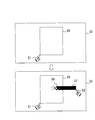
- FIG. 3 is a diagram illustrating an example of the operation screen.
- the operation screen 31 includes a first setting area 32, a drawing area 33, and a second setting area 34.
- the drawing area 33 is an area for performing a drawing operation using the first pointer and the second pointer.
- the first pointer and the second pointer are pointers that can be operated simultaneously and independently, and details will be described later.
- the user performs a drawing operation by touching the drawing area 33 of the operation screen 31 displayed on the touch panel unit 18.
- the first pointer and the second pointer can have different drawing functions.
- a shielding object drawing function can be assigned to the first pointer
- a spray drawing function can be assigned to the second pointer.
- the drawing function assigned to the first pointer is referred to as a first drawing function
- the drawing function assigned to the second pointer is referred to as a second drawing function.
- the first setting area 32 is an area for setting the first drawing function.
- the second setting area 34 is an area for setting the second drawing function.
- the first setting area 32 and the second setting area 34 include sub-areas 32a and 34a for setting a drawing function, respectively.
- any one of a shield, a range specification, and a drawing type can be selected. Since the first pointer is a pointer that is recognized by touching the drawing area 33 before the second pointer, the drawing function that will be operated first, such as a shielding object or range designation, is the first one. It is desirable that selection is possible only in the sub-area 34a for the pointer. Therefore, it is desirable that, for example, any one of the drawing types can be selected in the sub-area 34a for the second pointer. In the example of FIG. 3, the shielding object is selected in the first pointer sub-area 32a, and the spray is selected in the second pointer sub-area 34a.
- sub-areas for making detailed settings related to the selected drawing function are displayed in the empty areas of the first setting area 32 and the second setting area 34, respectively. Is done.
- the sub-area 32b for selecting any one of a plurality of shapes that can be selected as the shield
- the shield And a sub-area 32c for setting the size.
- spray is selected in the sub-area 34a
- the sub-area 34b for selecting one of a plurality of selectable spray spray shapes
- the sub-area 34c for setting the color of the spray
- spray A sub-area 34d for setting the size is displayed.
- range designation is selected as the drawing function, for example, a subarea for selecting an effect (gradation, blurring, mask, etc.) to be applied within the range is displayed.
- the operation determination unit 25 receives input information sent in response to the touch operation of the touch panel unit 18 via the OS 20, and determines a user operation on the touch panel unit 18 based on the received input information. Specifically, when at least one of a touch operation, a release operation, and a drag operation is detected in the touch panel unit 18, the operation determination unit 25 identifies operation information that can identify the operation and a position for specifying the operation position. Input information including information.
- the operation determining unit 25 determines that the operation is in the first setting area 32 or the second setting area 34 of the operation screen 31 based on the input information, the drawing function selected by the user based on the position information. And information about the detailed settings.
- the operation determination unit 25 stores the acquired information in the drawing setting table.
- the drawing setting table is stored in the RAM 12, for example.
- FIG. 4 is a diagram illustrating an example of a drawing setting table.
- the drawing setting table stores, for the first pointer and the second pointer, X and Y coordinates indicating the position of the pointer, a drawing function, detailed settings, and the like.
- position information included in the input information is set.
- the drawing function field of the first pointer the first drawing function selected in the sub area 32a of the first setting area 32 is set.
- information indicating the second drawing function selected in the sub area 34a of the second setting area 34 is set.
- the detailed setting field stores detailed setting information related to the drawing function according to the selected drawing function.
- the detailed setting fields include a first detailed setting field related to shape, a second detailed setting field related to size, a third detailed setting field related to color, and the like.
- a fourth detailed setting field related to effects such as gradation and blurring may be included.
- information selected in each sub area of the first setting area 32 and the second setting area 34 of the operation screen 31 is stored.
- the operation determination unit 25 determines whether or not the input information indicates a first touch in the drawing area 33.
- First touch means a state in which no contact operation other than the contact is performed in the drawing area 33. Therefore, the operation determination unit 25 determines that the touch operation indicated by the input information is the first touch when the touch operation or the drag operation is not performed in the drawing area 33 other than the touch operation indicated by the input information. judge.
- the operation determination unit 25 performs the second touch on the touch operation indicated by the input information. Is determined.
- the operation determination unit 25 When the operation determination unit 25 recognizes the operation of the first pointer, the operation determination unit 25 sets the position information in the X coordinate field and the Y coordinate field of the first pointer in the drawing setting table. When the operation determination unit 25 recognizes the operation of the second pointer, it sets the position information in the X coordinate field and the Y coordinate field of the second pointer in the drawing setting table.
- the operation determination unit 25 displays a first pointer at a position (X coordinate, Y coordinate) where the touch operation determined to be the first touch is performed, and performs a release operation and a drag operation that are transitioned from the touch operation. Recognized as a pointer operation. Specifically, after the first pointer is displayed, when the touch operation transitions to the drag operation, the first pointer moves to the coordinates specified by the position information sequentially input corresponding to the drag operation. Is done. Similarly, the operation determination unit 25 displays the second pointer at the position where the touch operation determined to be the second touch is performed, and the release operation and the drag operation transitioned from the touch operation are regarded as the operation of the second pointer. recognize.
- the operation determination unit 25 deletes the second pointer when the touch operation related to the second pointer is changed to the release operation.
- the operation determination unit 25 deletes each data of the X coordinate field and the Y coordinate field of the second pointer of the drawing setting table.
- the operation determination unit 25 deletes both the first pointer and the second pointer when the touch operation related to the first pointer is changed to the release operation.
- the operation determination unit 25 deletes each data of the X coordinate field and the Y coordinate field of the first pointer of the drawing setting table.
- the operation determination unit 25 When the operation determination unit 25 recognizes the operation of the first pointer, the operation determination unit 25 sends the operation information and information on the first pointer of the drawing setting table to the first generation unit 26. On the other hand, when the operation determination unit 25 recognizes the operation of the second pointer, the operation determination unit 25 sends the operation information and information on the second pointer of the drawing setting table to the second generation unit 27.
- FIG. 5 is a diagram showing a concept of drawing data generation processing by the first generation unit 26, the second generation unit 27, and the drawing data generation unit 28.
- the drawing data generation unit 28 generates drawing data to be finally displayed on the display unit of the touch panel unit 18.
- the drawing data generation unit 28 has a canvas 43 for the drawing data.
- the first generator 26 and the second generator 27 also have their own canvases 41 and 42, respectively.
- the canvases 41, 42, and 43 have the same size, and are stored on the RAM 12 as a memory area corresponding to the size, for example.
- the first generation unit 26 generates first drawing data including an image drawn by a drawing operation using the first pointer on the canvas 41.
- the second generation unit 27 generates second drawing data including an image drawn by a drawing operation using the second pointer on the canvas 42.
- a triangular shielding object is assigned to the first drawing function
- spray drawing is assigned to the second drawing function. Accordingly, drawing data in which the shielding object is drawn at the position pointed to by the first pointer is stored on the canvas 41, and drawing data that is spray-drawn at the position pointed to by the second pointer is stored on the canvas 42. Stored.
- the drawing data generation unit 28 generates drawing data obtained by combining the drawing data on the canvas 41 and the drawing data on the canvas 42 on the canvas 43 (see reference numeral 43 (2) in FIG. 5).
- the drawing data generation unit 28 applies a drawing effect corresponding to the first drawing function or the second drawing function to the drawing portion 46 where the first drawing data and the second drawing data overlap.
- a shielding effect corresponding to the shielding object designated as the first drawing function is applied to the drawing portion 46.
- the blurring effect is applied to the drawing portion 46.
- the drawing data generation unit 28 is newly synthesized with the existing drawing data (reference numeral 43 (1) in FIG. 5).
- Drawing data overwritten with the drawing data (reference numeral 43 (2) in FIG. 5) is generated (reference numeral 43 (3) in FIG. 5).
- the first drawing data is erased with the composition effect remaining. The This is the same when the range designation is designated in the first drawing function.
- the drawing data generation unit 28 displays the drawing data on the display unit of the touch panel unit 18 by sending the drawing data on the canvas 43 to the OS 20. Note that the synthesis of the first drawing data and the second drawing data by the drawing data generation unit 28 may be performed when one of the first drawing data and the second drawing data is updated, It may be executed at a predetermined cycle. Further, the drawing data on the canvas 43 may always be displayed on the display unit of the touch panel unit 18 by the action of the OS 20 or the like.
- FIG. 6 is a flowchart illustrating an operation example of the drawing apparatus 1 according to the first embodiment.
- the touch panel unit 18 sends to the main body unit 10 input information including position information (coordinate information) and operation information corresponding to the contact state regarding the detected contact operation.
- the drawing application 21 is notified of the input information acquisition via the OS 20.
- the operation determination unit 25 acquires this input information.
- the operation determination unit 25 determines a user operation corresponding to the input information (S601). The operation determination unit 25 determines whether the user operation is an operation in the drawing area 33 of the operation screen 31 based on the position information included in the input information (S602). If the operation determination unit 25 determines that the operation is not within the drawing area 33 (S602; NO), the operation determination unit 25 performs general processing according to the operation (S612).
- General operations include operations in the first setting area 32 and the second setting area 34 of the operation screen 31. If the user operation is a setting operation in the first setting area 32, the drawing function corresponding to the setting operation is set in the drawing setting table as the first drawing function. If the user operation is a setting operation in the second setting area 34, the drawing function corresponding to the setting operation is set in the drawing setting table as the second drawing function. In the drawing setting table, initial values may be set as the first drawing function and the second drawing function, respectively.
- the operation determination unit 25 determines whether the user operation is an operation in the drawing area 33 (S602; YES). Specifically, the operation determination unit 25 indicates that the operation information included in the input information indicates a touch operation, and no touch operation or drag operation is performed in the drawing area 33 other than the touch operation at that time. In this case, it is determined that the user operation is a first touch operation.
- the operation determination unit 25 determines that the user operation is the first touch operation (S603; YES)
- the operation determination unit 25 displays the first pointer at the position specified by the position information included in the input information (S604). Subsequently, the operation determination unit 25 sends drawing information related to the first pointer and the operation information thereof to the first generation unit 26.
- the drawing information related to the first pointer includes information (X coordinate and Y coordinate) indicating the position of the first pointer and information related to the drawing function, shape, size, color, etc. designated as the first drawing function.
- the operation determination unit 25 determines whether the user operation is related to the first pointer (S605).
- the user operation related to the first pointer corresponds to a drag operation or a release operation shifted from the first touch state. If the operation determination unit 25 determines that the operation is a user operation related to the first pointer (S605; YES), the operation determination unit 25 sends drawing information related to the first pointer and operation information thereof to the first generation unit 26.
- the first generation unit 26 acquires the drawing information and the operation information related to the first pointer from the operation determination unit 25, the first generation unit 26 generates first drawing data based on the information on the canvas 41 (S606).
- the operation determination unit 25 determines that the user operation is not a first touch operation (S603; NO) and is not a user operation related to the first pointer (S605; NO), does the user operation correspond to a second touch operation? It is determined whether or not (S607). Specifically, in the operation determination unit 25, the operation information included in the input information indicates a touch operation, and at that time, in addition to the touch operation, a touch operation or a drag operation is performed in the drawing area 33. In this case, it is determined that the user operation is a second touch operation. In addition to the touch operation, whether or not a touch operation or a drag operation is performed in the drawing area 33 is determined by, for example, determining whether or not the input information includes a plurality of pieces of operation information. You may implement
- the operation determination unit 25 determines that the user operation is a second touch operation (S607; YES)
- the operation determination unit 25 displays the second pointer at a position specified by the position information included in the input information (S608). Subsequently, the operation determination unit 25 sends drawing information relating to the second pointer and the operation information thereof to the second generation unit 27.
- the drawing information related to the second pointer includes information indicating the position of the second pointer (X coordinate and Y coordinate) and information related to the drawing function, shape, size, color, and the like designated as the second drawing function.
- the operation determining unit 25 determines that the user operation is not a second touch operation (S607; NO)
- the operation determining unit 25 sends drawing information about the second pointer and the operation information to the second generating unit 27.
- the operation determination unit 25 determines that the user operation is not the second touch operation
- the user operation is a user operation related to the second pointer. That is, the user operation corresponds to a drag operation or a release operation using the second pointer transitioned from the second touch.
- the second generation unit 27 acquires the drawing information and the operation information related to the second pointer from the operation determination unit 25, the second generation unit 27 generates second drawing data based on the information on the canvas 42 (S609).
- the drawing data generation unit 28 generates combined drawing data obtained by combining the first drawing data generated by the first generation unit 26 and the second drawing data generated by the second generation unit 27 (S610).
- the drawing data generation unit 28 gives a drawing effect corresponding to the first drawing function or the second drawing function to a drawing portion where the first drawing data and the second drawing data overlap in the creation of the composite drawing data.
- the composite drawing data generated by the drawing data generation unit 28 is sent to the touch panel unit 18 via the OS 20 and the UI controller 14. As a result, a screen corresponding to the combined drawing data is displayed on the display unit of the touch panel unit 18 (S611).
- FIG. 7 is a diagram illustrating a drawing example 1 performed by the drawing apparatus according to the first embodiment.
- the figure 55 is already drawn in the drawing area 33 of the operation screen 31.
- the user selects range designation as the first drawing function in the sub-area 32a of the first setting area 32 of the operation screen 31.
- a range-designated drawing function is selected in the sub-area 32a
- a range-designated shape selection screen is displayed in the sub-area 32b
- an effect selection screen within the range is displayed in the sub-area 32c.
- a square is selected as the shape for specifying the range
- blurring is selected as the effect within the range.
- the user selects a pen in the drawing type as the second drawing function in the sub-area 34a of the second setting area 34 of the operation screen 31.
- a pen thickness selection screen is displayed in the sub area 34b, and a pen color selection screen is displayed in the sub area 34c.
- a predetermined thickness is selected, and a predetermined color is selected.
- the touch panel operation may be performed using an article such as a touch pen.
- the user touches the drawing area 33 of the operation screen 31 displayed on the touch panel unit 18 with the finger of one arm. This operation is determined as a first touch operation in the drawing apparatus 1, and the first pointer 51 is displayed on the touch panel unit 18. Thereafter, the first pointer 51 moves following the movement of the touched finger.
- the user designates the range 56 by sliding the touched finger (first pointer 51).
- the range designation and the detailed setting designated as the first drawing function are reflected.
- the first generation unit 26 in the drawing apparatus 1 draws an image indicating the designated range 56 on its own campus 41.
- the user touches the finger on the touch panel as it is and touches the finger on the other arm to a predetermined position indicating the inside of the drawing area 33 of the operation screen 31 on the touch panel.
- This operation is determined as a second touch operation in the drawing apparatus 1, and the second pointer 52 is displayed on the touch panel unit 18. Thereafter, the second pointer 52 moves following the movement of the finger that has performed the second touch operation.
- the user performs drawing using the pen by sliding the finger (second pointer 52) that has performed the second touch operation.
- the pen drawing 57 drawn by the pen drawing reflects the pen drawing function designated as the second drawing function and its detailed settings.
- the second generation unit 27 in the drawing apparatus 1 draws the pen image 57 on its own campus 42.
- the drawing data generation unit 28 generates combined drawing data of the range 56 drawn by the first pointer 51 and the pen drawing 57 drawn by the second pointer 52, and displays the combined drawing data on the touch panel unit 18. At this time, as shown in the example of FIG. 7, a part of the pen image 57 is included in the range 56.
- the drawing data generation unit 28 imparts a blurring effect as a range designation attribute to the portion 58 of the pen drawing 57 included in the range 56 drawn by the first pointer 51.
- the second pointer 52 is erased and the pen image 57 is determined.
- the first pointer 51 is erased and the image indicating the range 56 disappears.
- FIG. 8 is a diagram illustrating a drawing example 2 using the drawing apparatus according to the first embodiment.
- the range designation is selected as the first drawing function
- the square is selected as the shape of the range designation
- the gradation is selected as the effect within the range.
- a pen is designated as the second drawing function, and a predetermined thickness and a predetermined color are selected.
- a gradation effect as a range designation attribute is applied to the portion 59 of the pen image 57 included in the range 56 drawn by the first pointer 51.
- FIG. 9 is a diagram illustrating a drawing example 3 using the drawing apparatus according to the first embodiment.
- FIG. 9 shows an example in which drawing types are selected for the first drawing function and the second drawing function, respectively. Specifically, the pen is selected as the first drawing function, and the spray is selected as the second drawing function.
- the pen image 61 is created using the first pointer 51, and the spray image 62 is created using the second pointer 52.
- the pen image 61 is prioritized for the portion where the pen image 61 and the spray image 62 overlap. As a result, the pen image 61 is overwritten on the spray image 62.
- the drawing apparatus 1 in the first embodiment the first pointer and the second pointer are displayed simultaneously in response to a plurality of contact operations performed independently on the touch panel unit 18.
- Different drawing functions can be designated as the first drawing function and the second drawing function for the first pointer and the second pointer, respectively, and information regarding each drawing function is stored in the drawing setting table.
- each drawing data corresponding to the first drawing function and the second drawing function is generated by the drawing operation in the drawing area 33 using the first pointer and the second pointer, and these drawing data are synthesized.
- the composite drawing data is displayed on the touch panel unit 18.
- the user who uses the drawing apparatus 1 according to the first embodiment can draw by the same operation as when actually drawing with both hands. Therefore, spray art using a pattern with one hand and spraying with the other hand can also be realized by an easy operation. According to the first embodiment, since drawing using both hands is possible, the operability of drawing is improved as compared with the prior art.
- drawing functions can be set for the first pointer and the second pointer, drawing functions according to various user requests can be provided.
- FIG. 10 is a diagram showing an example of a drawing setting table in the modification.
- a priority field may be added to the drawing setting table to store priorities related to the first drawing function and the second drawing function.
- priority information selected in each of the sub-areas of the first setting area 32 and the second setting area 34 of the operation screen 31 is stored.
- the drawing data generation unit 28 designates drawing types as the first drawing function and the second drawing function
- priority is given based on the priority information stored in the drawing setting table.
- a high-level drawing function may be preferentially applied.
- the priority application is, for example, overwriting.
- the drawing device 1 in the above-described first embodiment includes the touch panel unit 18, and a user operation is performed using the touch panel unit 18.
- the drawing apparatus 1 may include user operation input means other than the touch panel unit 18.
- FIG. 10 is a diagram illustrating a hardware configuration example of a drawing apparatus according to a modification.
- An example of the above-described user operation input means is a mouse.
- the touch panel unit 18 and the mouse 71 may be connected to the UI controller 14, or at least two mice 71 may be connected instead of the touch panel unit 18.
- the operation determination unit 25 in the modification may not determine the first touch operation and the second touch operation.
- the first generator 26 generates an image drawn with the mouse 71 (1) corresponding to the first pointer
- the second generator 27 generates an image drawn with the mouse 71 (2) corresponding to the second pointer. You just have to do it.
- the pointer corresponding to the mouse 71 is displayed by the OS 20.
- the operation determination unit 25 in the modification example has the mouse 71.
- the pointer corresponding to may be determined as the first pointer. In this case, when an operation in the drawing area 33 using the touch panel is performed in a state where the pointer corresponding to the mouse 71 is displayed in the drawing area 33, the contact operation is determined as the second touch operation.
- the contact operation is determined as the first operation. Except for the determination processing of the first pointer and the second pointer, it may be the same as in the first embodiment.
- a hardware component is a hardware circuit, for example, a field programmable gate array (FPGA), an application specific integrated circuit (ASIC), a gate array, a combination of logic gates, a signal processing circuit, an analog circuit, etc. There is.
- FPGA field programmable gate array
- ASIC application specific integrated circuit
- Software components are parts (fragments) that realize the above processing as software, and are not a concept that limits the language, development environment, etc. that realizes the software.
- Examples of software components include tasks, processes, threads, drivers, firmware, databases, tables, functions, procedures, subroutines, predetermined portions of program code, data structures, arrays, variables, parameters, and the like.
- These software components are realized on one or a plurality of memories (for example, one or a plurality of processors (for example, CPU (Central Processing Unit), DSP (Digital Signal Processing), etc.)).
- Each processing unit may be configured as a hardware component, a software component, or a combination thereof by a method that can be realized by a normal engineer in this technical field.
Landscapes
- Engineering & Computer Science (AREA)
- Theoretical Computer Science (AREA)
- Physics & Mathematics (AREA)
- General Physics & Mathematics (AREA)
- General Engineering & Computer Science (AREA)
- Human Computer Interaction (AREA)
- User Interface Of Digital Computer (AREA)
- Processing Or Creating Images (AREA)
Abstract
A drawing device is provided with a pointer control means for detecting operations using a first pointer and a second pointer, respectively, in a drawing area, a first generating means for generating first drawing data in accordance with a first drawing function specified for the first pointer and the operation using the first pointer in the drawing area, a second generating means for generating second drawing data in accordance with a second drawing function specified for the second pointer and the operation using the second pointer in the drawing area, and a drawing means for generating drawing data which provides the drawing effect corresponding to the first drawing function or the second drawing function on the drawing portion in which the first drawing data and the second drawing data overlap each other, thereby improving the operability of drawing.
Description
本発明は、描画技術に関する。
The present invention relates to a drawing technique.
現在、様々な描画機能を持つ描画アプリケーションが存在する。このような描画アプリケーションでは、鉛筆、ブラシ、スプレー等のような所望の描画形態を選択することができ、ぼかしやグラデーション等のような様々な描画効果を付加することができる。
Currently, there are drawing applications with various drawing functions. In such a drawing application, a desired drawing form such as a pencil, a brush, and a spray can be selected, and various drawing effects such as blurring and gradation can be added.
関連して、第1カーソルと第2カーソルとを表示し、移動対象のカーソルを切り替えて、第1カーソルを用いて指定された描画情報と、第2カーソルを用いて指定された画面上への描画と、に基づいて画面上へ描画する図形処理装置が知られている(下記特許文献1参照)。
Relatedly, the first cursor and the second cursor are displayed, the cursor to be moved is switched, and the drawing information designated using the first cursor and the screen designated using the second cursor are displayed. 2. Description of the Related Art A graphic processing apparatus that draws on a screen based on drawing is known (see Patent Document 1 below).
しかしながら、従来の描画アプリケーションでは、所望の描画機能の選択、描画エリアにおける描画指定、描画機能の切り替えというように、ユーザがポインタ(カーソル)を頻繁に移動させる必要があり操作が煩雑になる傾向にあった。従来の描画アプリケーションのユーザインタフェースが1つのポインタを用いて実現されていることがその問題の1つの原因である。上述の第1カーソルと第2カーソルとを用いた図形処理装置においても、描画指定するのは第2カーソルのみであり、第1カーソルは描画情報の指定のために利用されている。
However, in a conventional drawing application, the user needs to frequently move the pointer (cursor) such as selecting a desired drawing function, drawing designation in the drawing area, and switching of the drawing function, and the operation tends to be complicated. there were. One cause of the problem is that the user interface of the conventional drawing application is realized by using one pointer. Also in the graphic processing apparatus using the first cursor and the second cursor described above, only the second cursor is designated for drawing, and the first cursor is used for designating drawing information.
また、コンピュータ上ではなく実際に手を使って描画する場合には、両手を使って描画作業を行う場合がある。例えば、一方の手で型紙を支え、他方の手でスプレーを吹き付けることで、型紙に沿った模様を描画する場合等である。従来の描画アプリケーションでは、このような両手を使った描画作業が実現されていなかった。
Also, when drawing with hands instead of on the computer, drawing work may be performed with both hands. For example, the pattern is drawn along the pattern by supporting the pattern with one hand and spraying with the other hand. In a conventional drawing application, such a drawing operation using both hands has not been realized.
本発明の一態様に係る課題は、このような問題点に鑑み、描画の操作性を向上させる描画技術を提供することにある。
In view of such problems, an object of one embodiment of the present invention is to provide a drawing technique that improves the operability of drawing.
本発明の各態様では、上述した課題を解決するために、それぞれ以下の構成を採用する。
Each aspect of the present invention employs the following configurations in order to solve the above-described problems.
第1態様は、描画装置に関する。第1態様に係る描画装置は、描画領域内における第1ポインタ及び第2ポインタを用いた各操作をそれぞれ検出するポインタ制御手段と、第1ポインタのために指定された第1描画機能及び第1ポインタを用いた上記描画領域での操作に応じた第1描画データを生成する第1生成手段と、第2ポインタのために指定された第2描画機能及び第2ポインタを用いた上記描画領域での操作に応じた第2描画データを生成する第2生成手段と、上記第1描画データ及び第2描画データが重なり合う描画部分に上記第1描画機能又は第2描画機能に対応する描画効果を与えた描画データを生成する描画手段と、を備える。
The first aspect relates to a drawing apparatus. The drawing apparatus according to the first aspect includes pointer control means for detecting each operation using the first pointer and the second pointer in the drawing area, the first drawing function designated for the first pointer, and the first First generation means for generating first drawing data according to an operation in the drawing area using the pointer, a second drawing function designated for the second pointer, and the drawing area using the second pointer A second generating means for generating second drawing data according to the operation of the first drawing function, and a drawing effect corresponding to the first drawing function or the second drawing function is applied to a drawing portion where the first drawing data and the second drawing data overlap. Drawing means for generating the drawn data.
なお、本発明の他の態様として、以上の構成を実現する方法、プログラム、このプログラムを記録したコンピュータが読み取り可能な記憶媒体等であってもよい。
Note that, as another aspect of the present invention, a method, a program, a computer-readable storage medium storing the program, or the like that realizes the above configuration may be used.
上記各態様によれば、描画の操作性を向上させる描画技術を提供することができる。
According to each aspect described above, it is possible to provide a drawing technique that improves the operability of drawing.
以下、実施形態としての描画装置について具体例を挙げ説明する。以下に挙げた各実施例はそれぞれ例示であり、本実施形態は以下の各実施例の構成に限定されない。
Hereinafter, a specific example of the drawing apparatus as the embodiment will be described. Each example given below is an example, and the present embodiment is not limited to the configuration of each example below.
以下、実施例1における描画装置について説明する。
Hereinafter, the drawing apparatus according to the first embodiment will be described.
[装置構成]
図1は、実施例1における描画装置のハードウェア構成例を示す図である。実施例1における描画装置1は、ハードウェア構成として、本体ユニット10、ユーザインタフェースユニット等を有する。本体ユニット10は、CPU(Central Processing System)11、RAM(Random Access Memory)12、ハードディスクドライブ(以降、HDDと表記する)13、ユーザインタフェースコントローラ(以降、UIコントローラと表記する)14等を含む。CPU11、RAM12、HDD13、UIコントローラ14はそれぞれバス15により接続される。 [Device configuration]
FIG. 1 is a diagram illustrating a hardware configuration example of a drawing apparatus according to the first embodiment. Thedrawing apparatus 1 according to the first embodiment includes a main unit 10 and a user interface unit as a hardware configuration. The main unit 10 includes a CPU (Central Processing System) 11, a RAM (Random Access Memory) 12, a hard disk drive (hereinafter referred to as HDD) 13, a user interface controller (hereinafter referred to as UI controller) 14, and the like. The CPU 11, RAM 12, HDD 13, and UI controller 14 are connected by a bus 15.
図1は、実施例1における描画装置のハードウェア構成例を示す図である。実施例1における描画装置1は、ハードウェア構成として、本体ユニット10、ユーザインタフェースユニット等を有する。本体ユニット10は、CPU(Central Processing System)11、RAM(Random Access Memory)12、ハードディスクドライブ(以降、HDDと表記する)13、ユーザインタフェースコントローラ(以降、UIコントローラと表記する)14等を含む。CPU11、RAM12、HDD13、UIコントローラ14はそれぞれバス15により接続される。 [Device configuration]
FIG. 1 is a diagram illustrating a hardware configuration example of a drawing apparatus according to the first embodiment. The
実施例1におけるユーザインタフェースユニットには、タッチパネルユニット18が適用される。実施例1における描画装置1は、このようなハードウェア構成を有するパーソナルコンピュータ等の汎用コンピュータで実現されてもよいし、専用コンピュータで実現されてもよい。本実施形態は、この描画装置1のハードウェア構成を限定するものではない。
The touch panel unit 18 is applied to the user interface unit in the first embodiment. The drawing apparatus 1 according to the first embodiment may be realized by a general-purpose computer such as a personal computer having such a hardware configuration, or may be realized by a dedicated computer. This embodiment does not limit the hardware configuration of the drawing apparatus 1.
タッチパネルユニット18は、表示部、ユーザ操作を受け付けるタッチパネル、制御部等を含む。タッチパネルユニット18は、本体ユニット10から送られる描画データに応じた画像を表示部に表示させ、タッチパネルへの外部からの接触を感知することによりユーザからの入力を得る。タッチパネルユニット18は、取得された入力情報を本体ユニット10へ送る。
The touch panel unit 18 includes a display unit, a touch panel that receives user operations, a control unit, and the like. The touch panel unit 18 displays an image corresponding to the drawing data sent from the main unit 10 on the display unit, and obtains an input from the user by sensing an external contact with the touch panel. The touch panel unit 18 sends the acquired input information to the main unit 10.
この入力情報には、パネル上の接触位置に対応する位置情報(座標情報)及び接触状態に対応する操作情報等が含まれる。ここでの操作情報には、ユーザがタッチパネルに触れる操作(以降、タッチ操作と表記する)、ユーザがタッチパネルを離す操作(以降、リリース操作と表記する)、ユーザがパネルに触れたままその触れた箇所を移動させる操作(以降、ドラッグ操作と表記する)等を識別可能な情報が含まれる。これら位置情報及び操作情報は、例えば、タッチパネルユニット18内の制御部が生成する。
This input information includes position information (coordinate information) corresponding to the contact position on the panel, operation information corresponding to the contact state, and the like. The operation information here includes an operation in which the user touches the touch panel (hereinafter referred to as a touch operation), an operation in which the user releases the touch panel (hereinafter referred to as a release operation), and a touch of the user while touching the panel. Information that can identify an operation of moving a location (hereinafter referred to as a drag operation) or the like is included. For example, the position information and the operation information are generated by the control unit in the touch panel unit 18.
タッチパネルユニット18の制御部は、タッチパネルから所定の周期(サンプリング周期等)で逐次出力される接触位置を示す信号を参照し、この信号に基づいて上記各操作を判定する。当該制御部は、接触を示す信号を受信するとタッチ操作の発生を検知する。制御部は、このタッチ操作の検知後、所定の間、接触信号が受信されない場合に、リリース操作の発生を検知する。また、制御部は、当該接触信号に基づいて接触の移動を検知することにより、その操作をドラッグ操作と判定する。なお、タッチ操作、ドラッグ操作及びリリース操作については本体ユニット10側で判定されるようにしてもよい。この場合、タッチパネルユニット18は、接触位置を示す信号を所定の周期(サンプリング周期等)で本体ユニット10へ逐次出力するようにすればよい。
The control unit of the touch panel unit 18 refers to a signal indicating a contact position that is sequentially output from the touch panel at a predetermined cycle (sampling cycle or the like), and determines each operation based on this signal. The control unit detects the occurrence of a touch operation when receiving a signal indicating contact. A control part detects generation | occurrence | production of release operation, when a contact signal is not received for a predetermined period after detecting this touch operation. Further, the control unit determines the operation as a drag operation by detecting the movement of the contact based on the contact signal. Note that the touch operation, the drag operation, and the release operation may be determined on the main unit 10 side. In this case, the touch panel unit 18 may sequentially output a signal indicating the contact position to the main unit 10 at a predetermined cycle (sampling cycle or the like).
実施例1におけるタッチパネルユニット18は、異なる複数位置での同時接触も感知可能である。例えば、ユーザが両手でタッチパネルの異なる位置に触れた場合であっても、タッチパネルユニット18は、各位置での接触をそれぞれ感知し、各接触を示す各入力情報をそれぞれ本体ユニット10へ送る。本体ユニット10は、例えば、一度に受信された情報に複数の入力情報が含まれている場合に、複数位置での同時接触が発生したと判断することができる。
The touch panel unit 18 according to the first embodiment can sense simultaneous contact at a plurality of different positions. For example, even when the user touches different positions on the touch panel with both hands, the touch panel unit 18 senses contact at each position and sends each input information indicating each contact to the main unit 10. For example, the main unit 10 can determine that simultaneous contact at a plurality of positions has occurred when a plurality of pieces of input information are included in the information received at one time.
UIコントローラ14は、タッチパネル18と接続され、タッチパネルユニット18へ描画データを送信し、タッチパネルユニット18から入力情報及び操作情報を受信する。なお、本実施形態は、タッチパネルユニット18と本体ユニット10との間のインタフェースを限定するものではない。
The UI controller 14 is connected to the touch panel 18, transmits drawing data to the touch panel unit 18, and receives input information and operation information from the touch panel unit 18. In the present embodiment, the interface between the touch panel unit 18 and the main unit 10 is not limited.
CPU11は、1又は複数のプロセッサであり、RAM12、ROM(図示せず)、インタフェース回路(図示せず)等の周辺回路、HDD13等を用いて動作する。
The CPU 11 is one or a plurality of processors and operates using peripheral circuits such as a RAM 12, a ROM (not shown), an interface circuit (not shown), an HDD 13, and the like.
図2は、実施例1における描画装置の処理構成例を示すブロック図である。実施例1における描画装置1は、操作画面制御部24、操作判定部25、第1描画データ生成部(以降、第1生成部と表記する)26、第2描画データ生成部(以降、第2生成部と表記する)27、描画データ生成部28等を有する。これら処理部は、ハードウェア構成要素として実現されてもよいし、HDD13やROM(図示せず)等に格納されるプログラムがCPU11により実行されることによりソフトウェア構成要素として実現されてもよい([その他]の項参照)。
FIG. 2 is a block diagram illustrating a processing configuration example of the drawing apparatus according to the first embodiment. The drawing apparatus 1 according to the first embodiment includes an operation screen control unit 24, an operation determination unit 25, a first drawing data generation unit (hereinafter referred to as a first generation unit) 26, a second drawing data generation unit (hereinafter referred to as a second drawing data generation unit). 27), a drawing data generation unit 28, and the like. These processing units may be realized as hardware components, or may be realized as software components by executing a program stored in the HDD 13 or ROM (not shown) by the CPU 11 ([[ See the “Others” section).
図2は、各処理部がソフトウェア構成要素として実現された場合の例を示す。この場合、HDD13やROM(図示せず)等に格納されるプログラムがCPU11により実行されることによりOS(Operating System)20が起動される。OS20は、上述のUIコントローラ14等の入出力を制御する。OS20は、各種アプリケーションのタスク管理を行いながら、これらアプリケーションとUIコントローラ14等との間のインタフェースとして動作する。
FIG. 2 shows an example in which each processing unit is realized as a software component. In this case, an OS (Operating System) 20 is started by the CPU 11 executing a program stored in the HDD 13 or ROM (not shown). The OS 20 controls input / output of the above-described UI controller 14 and the like. The OS 20 operates as an interface between these applications and the UI controller 14 while performing task management of various applications.
具体的には、OS20は、タッチパネルユニット18で接触操作が感知されるとこの接触操作に対応する入力情報をUIコントローラ14から受信する。OS20は、受信された入力情報をタスク管理する各アプリケーションにそれぞれ通知する。また、OS20は、描画アプリケーション21から描画データと共に表示指示を受けると、その描画データに対応する画像をタッチパネルユニット18の表示部に表示させるようにUIコントローラ14を制御する。
Specifically, when a touch operation is detected by the touch panel unit 18, the OS 20 receives input information corresponding to the touch operation from the UI controller 14. The OS 20 notifies each application that performs task management of the received input information. Further, when the OS 20 receives a display instruction together with the drawing data from the drawing application 21, the OS 20 controls the UI controller 14 to display an image corresponding to the drawing data on the display unit of the touch panel unit 18.
描画アプリケーション21は、OS20の制御の下、HDD13やROM(図示せず)等に格納されるプログラムがCPU11により実行されることにより実現される。図2の例では、描画アプリケーション21が、操作画面制御部24、操作判定部25、第1生成部26、第2生成部27及び描画データ生成部28を当該ソフトウェア構成要素として実現する。描画アプリケーション21は、これら処理部を実行することにより、独立して同時操作可能な2つのポインタ(以降、第1ポインタ及び第2ポインタと表記する)を用いた描画を可能とする。
The drawing application 21 is realized by the CPU 11 executing a program stored in the HDD 13 or ROM (not shown) under the control of the OS 20. In the example of FIG. 2, the drawing application 21 implements the operation screen control unit 24, the operation determination unit 25, the first generation unit 26, the second generation unit 27, and the drawing data generation unit 28 as the software components. By executing these processing units, the drawing application 21 can perform drawing using two pointers (hereinafter referred to as a first pointer and a second pointer) that can be operated simultaneously and independently.
操作画面制御部24は、描画アプリケーション21が起動されると、操作画面データを生成し、この操作画面をタッチパネルユニット18の表示部に表示させる。図3は、操作画面の例を示す図である。操作画面31は、第1設定エリア32、描画エリア33、第2設定エリア34を含む。
When the drawing application 21 is activated, the operation screen control unit 24 generates operation screen data and displays the operation screen on the display unit of the touch panel unit 18. FIG. 3 is a diagram illustrating an example of the operation screen. The operation screen 31 includes a first setting area 32, a drawing area 33, and a second setting area 34.
描画エリア33は、第1ポインタ及び第2ポインタを用いた描画操作を行うためのエリアである。第1ポインタ及び第2ポインタはそれぞれ独立して同時操作可能なポインタであり、詳細については後述する。ユーザは、タッチパネルユニット18に表示された操作画面31の描画エリア33内をタッチすることで描画操作を行う。描画エリア33の描画操作では、第1ポインタ及び第2ポインタにそれぞれ異なる描画機能を持たせることができる。例えば、第1ポインタに遮蔽物の描画機能を割り当て、第2ポインタにスプレーの描画機能を割り当てることができる。以降、第1ポインタに割り当てられる描画機能を第1描画機能と表記し、第2ポインタに割り当てられる描画機能を第2描画機能と表記する。
The drawing area 33 is an area for performing a drawing operation using the first pointer and the second pointer. The first pointer and the second pointer are pointers that can be operated simultaneously and independently, and details will be described later. The user performs a drawing operation by touching the drawing area 33 of the operation screen 31 displayed on the touch panel unit 18. In the drawing operation of the drawing area 33, the first pointer and the second pointer can have different drawing functions. For example, a shielding object drawing function can be assigned to the first pointer, and a spray drawing function can be assigned to the second pointer. Hereinafter, the drawing function assigned to the first pointer is referred to as a first drawing function, and the drawing function assigned to the second pointer is referred to as a second drawing function.
第1設定エリア32は、第1描画機能を設定するためのエリアである。第2設定エリア34は、第2描画機能を設定するためのエリアである。第1設定エリア32及び第2設定エリア34にはそれぞれ描画機能を設定するためのサブエリア32a及び34aが含まれる。
The first setting area 32 is an area for setting the first drawing function. The second setting area 34 is an area for setting the second drawing function. The first setting area 32 and the second setting area 34 include sub-areas 32a and 34a for setting a drawing function, respectively.
第1ポインタのためのサブエリア32aでは、例えば、遮蔽物、範囲指定、及び描画タイプ(ペン、スプレー等)のいずれか1つが選択可能である。第1ポインタは、第2ポインタよりも先に描画エリア33へ接触することにより認識されるポインタであるため、遮蔽物や範囲指定等のように先に操作されるであろう描画機能は第1ポインタのためのサブエリア34aでのみ選択可能とすることが望ましい。よって、第2ポインタのためのサブエリア34aでは、例えば、描画タイプのうちのいずれか1つが選択可能とすることが望ましい。図3の例では、第1ポインタのサブエリア32aで遮蔽物が選択され、第2ポインタのサブエリア34aでスプレーが選択されている。
In the sub-area 32a for the first pointer, for example, any one of a shield, a range specification, and a drawing type (pen, spray, etc.) can be selected. Since the first pointer is a pointer that is recognized by touching the drawing area 33 before the second pointer, the drawing function that will be operated first, such as a shielding object or range designation, is the first one. It is desirable that selection is possible only in the sub-area 34a for the pointer. Therefore, it is desirable that, for example, any one of the drawing types can be selected in the sub-area 34a for the second pointer. In the example of FIG. 3, the shielding object is selected in the first pointer sub-area 32a, and the spray is selected in the second pointer sub-area 34a.
サブエリア32a及び34aにおいてそれぞれ描画機能が選択されると、第1設定エリア32及び第2設定エリア34の各空きエリアに、当該選択された描画機能に関する詳細設定を行うためのサブエリアがそれぞれ表示される。図3の例のように、例えば、サブエリア32aにおいて遮蔽物が選択された場合には、遮蔽物として選択可能な複数形状のいずれか1つを選択するためのサブエリア32bと、その遮蔽物のサイズを設定するためのサブエリア32cとが表示される。サブエリア34aにおいてスプレーが選択された場合には、選択可能な複数のスプレー吹き付け形状のいずれか1つを選択するためのサブエリア34bと、スプレーの色を設定するためのサブエリア34cと、吹き付けサイズを設定するためのサブエリア34dとが表示される。また、描画機能として範囲指定が選択された場合には、例えば、範囲内に施す効果(グラデーション、ぼかし、マスク等)を選択するためのサブエリアが表示される。
When a drawing function is selected in each of the sub-areas 32a and 34a, sub-areas for making detailed settings related to the selected drawing function are displayed in the empty areas of the first setting area 32 and the second setting area 34, respectively. Is done. As shown in the example of FIG. 3, for example, when a shield is selected in the sub-area 32a, the sub-area 32b for selecting any one of a plurality of shapes that can be selected as the shield, and the shield And a sub-area 32c for setting the size. When spray is selected in the sub-area 34a, the sub-area 34b for selecting one of a plurality of selectable spray spray shapes, the sub-area 34c for setting the color of the spray, and spray A sub-area 34d for setting the size is displayed. When range designation is selected as the drawing function, for example, a subarea for selecting an effect (gradation, blurring, mask, etc.) to be applied within the range is displayed.
操作判定部25は、タッチパネルユニット18の接触操作に応じて送られる入力情報をOS20を介して受信し、この受信された入力情報に基づいてタッチパネルユニット18におけるユーザ操作を判定する。具体的には、操作判定部25は、タッチパネルユニット18においてタッチ操作、リリース操作及びドラッグ操作の少なくとも1つが検知されると、その操作を識別可能な操作情報とその操作位置を特定するための位置情報とを含む入力情報を得る。
The operation determination unit 25 receives input information sent in response to the touch operation of the touch panel unit 18 via the OS 20, and determines a user operation on the touch panel unit 18 based on the received input information. Specifically, when at least one of a touch operation, a release operation, and a drag operation is detected in the touch panel unit 18, the operation determination unit 25 identifies operation information that can identify the operation and a position for specifying the operation position. Input information including information.
操作判定部25は、この入力情報に基づいて、操作画面31の第1設定エリア32又は第2設定エリア34内の操作であると判断すると、その位置情報に基づいてユーザにより選択された描画機能及びその詳細設定に関する情報を取得する。操作判定部25は、取得された情報を描画設定テーブルに格納する。描画設定テーブルは、例えば、RAM12に格納される。
When the operation determining unit 25 determines that the operation is in the first setting area 32 or the second setting area 34 of the operation screen 31 based on the input information, the drawing function selected by the user based on the position information. And information about the detailed settings. The operation determination unit 25 stores the acquired information in the drawing setting table. The drawing setting table is stored in the RAM 12, for example.
図4は、描画設定テーブルの例を示す図である。描画設定テーブルには、第1ポインタ及び第2ポインタについて、ポインタの位置を示すX座標及びY座標、描画機能、詳細設定などが格納される。X座標フィールド及びY座標フィールドには、入力情報に含まれる位置情報がそれぞれ設定される。第1ポインタの描画機能フィールドには、第1設定エリア32のサブエリア32aで選択された第1描画機能が設定される。第2ポインタの描画機能フィールドには、第2設定エリア34のサブエリア34aで選択された第2描画機能を示す情報が設定される。
FIG. 4 is a diagram illustrating an example of a drawing setting table. The drawing setting table stores, for the first pointer and the second pointer, X and Y coordinates indicating the position of the pointer, a drawing function, detailed settings, and the like. In the X coordinate field and the Y coordinate field, position information included in the input information is set. In the drawing function field of the first pointer, the first drawing function selected in the sub area 32a of the first setting area 32 is set. In the drawing function field of the second pointer, information indicating the second drawing function selected in the sub area 34a of the second setting area 34 is set.
詳細設定フィールドは、選択されている描画機能に応じてその描画機能に関する詳細設定情報を格納する。詳細設定フィールドとしては、図4の例に示すように、形状に関する第1詳細設定フィールド、サイズに関する第2詳細設定フィールド、色に関する第3詳細設定フィールド等が含まれる。この他、グラデーション、ぼかし等の効果に関する第4詳細設定フィールドが含まれていてもよい。各詳細設定フィールドには、操作画面31の第1設定エリア32及び第2設定エリア34の各サブエリアで選択された情報がそれぞれ格納される。
The detailed setting field stores detailed setting information related to the drawing function according to the selected drawing function. As shown in the example of FIG. 4, the detailed setting fields include a first detailed setting field related to shape, a second detailed setting field related to size, a third detailed setting field related to color, and the like. In addition, a fourth detailed setting field related to effects such as gradation and blurring may be included. In each detailed setting field, information selected in each sub area of the first setting area 32 and the second setting area 34 of the operation screen 31 is stored.
操作判定部25は、入力情報に基づいて、操作画面31の描画エリア33内の操作であると判断すると、ポインタ制御処理を行う。このポインタ制御処理において、操作判定部25は、当該入力情報が描画エリア33内におけるファーストタッチを示すか否かを判定する。ファーストタッチとは、描画エリア33内でその接触以外の接触操作が行われていない状態を意味する。よって、操作判定部25は、その入力情報により示されるタッチ操作以外に描画エリア33内でタッチ操作又はドラッグ操作がそのとき行われていない場合に、その入力情報により示されるタッチ操作をファーストタッチと判定する。一方で、操作判定部25は、その入力情報により示されるタッチ操作以外に描画エリア33内でタッチ操作又はドラッグ操作がそのとき行われている場合に、その入力情報により示されるタッチ操作をセカンドタッチと判定する。
If the operation determination unit 25 determines that the operation is in the drawing area 33 of the operation screen 31 based on the input information, the operation determination unit 25 performs a pointer control process. In this pointer control process, the operation determination unit 25 determines whether or not the input information indicates a first touch in the drawing area 33. First touch means a state in which no contact operation other than the contact is performed in the drawing area 33. Therefore, the operation determination unit 25 determines that the touch operation indicated by the input information is the first touch when the touch operation or the drag operation is not performed in the drawing area 33 other than the touch operation indicated by the input information. judge. On the other hand, when the touch operation or the drag operation is performed in the drawing area 33 other than the touch operation indicated by the input information, the operation determination unit 25 performs the second touch on the touch operation indicated by the input information. Is determined.
操作判定部25は、第1ポインタの操作を認識すると、描画設定テーブルにおける第1ポインタのX座標フィールド及びY座標フィールドにその位置情報を設定する。操作判定部25は、第2ポインタの操作を認識すると、描画設定テーブルにおける第2ポインタのX座標フィールド及びY座標フィールドにその位置情報を設定する。
When the operation determination unit 25 recognizes the operation of the first pointer, the operation determination unit 25 sets the position information in the X coordinate field and the Y coordinate field of the first pointer in the drawing setting table. When the operation determination unit 25 recognizes the operation of the second pointer, it sets the position information in the X coordinate field and the Y coordinate field of the second pointer in the drawing setting table.
操作判定部25は、ファーストタッチと判定されたタッチ操作が行われた位置(X座標、Y座標)に第1ポインタを表示し、そのタッチ操作から遷移されるリリース操作及びドラッグ操作をその第1ポインタの操作と認識する。具体的には、第1ポインタを表示後、そのタッチ操作がドラッグ操作に遷移した場合には、第1ポインタは、そのドラッグ操作に対応して逐次入力される位置情報で特定される座標に移動される。同様に、操作判定部25は、セカンドタッチと判定されたタッチ操作が行われた位置に第2ポインタを表示し、そのタッチ操作から遷移されるリリース操作及びドラッグ操作をその第2ポインタの操作と認識する。
The operation determination unit 25 displays a first pointer at a position (X coordinate, Y coordinate) where the touch operation determined to be the first touch is performed, and performs a release operation and a drag operation that are transitioned from the touch operation. Recognized as a pointer operation. Specifically, after the first pointer is displayed, when the touch operation transitions to the drag operation, the first pointer moves to the coordinates specified by the position information sequentially input corresponding to the drag operation. Is done. Similarly, the operation determination unit 25 displays the second pointer at the position where the touch operation determined to be the second touch is performed, and the release operation and the drag operation transitioned from the touch operation are regarded as the operation of the second pointer. recognize.
これにより、描画エリア33内において、異なる複数位置での同時接触が感知された場合には、第1ポインタ及び第2ポインタが同時に表示される。操作判定部25は、第2ポインタを表示後、この第2ポインタに関するタッチ操作がリリース操作に遷移した場合には、第2ポインタを消去する。操作判定部25は、第2ポインタを消去すると、描画設定テーブルの第2ポインタのX座標フィールド及びY座標フィールドの各データを消去する。また、操作判定部25は、第1ポインタ及び第2ポインタを表示後、第1ポインタに関するタッチ操作がリリース操作に遷移した場合には、第1ポインタ及び第2ポインタを共に消去する。操作判定部25は、第1ポインタを消去すると、描画設定テーブルの第1ポインタのX座標フィールド及びY座標フィールドの各データを消去する。
Thereby, in the drawing area 33, when simultaneous contact at a plurality of different positions is detected, the first pointer and the second pointer are displayed simultaneously. After the second pointer is displayed, the operation determination unit 25 deletes the second pointer when the touch operation related to the second pointer is changed to the release operation. When the operation determination unit 25 deletes the second pointer, the operation determination unit 25 deletes each data of the X coordinate field and the Y coordinate field of the second pointer of the drawing setting table. In addition, after displaying the first pointer and the second pointer, the operation determination unit 25 deletes both the first pointer and the second pointer when the touch operation related to the first pointer is changed to the release operation. When the operation determination unit 25 deletes the first pointer, the operation determination unit 25 deletes each data of the X coordinate field and the Y coordinate field of the first pointer of the drawing setting table.
操作判定部25は、第1ポインタの操作を認識すると、その操作情報及び描画設定テーブルの第1ポインタに関する情報を第1生成部26へ送る。一方、操作判定部25は、第2ポインタの操作を認識すると、その操作情報及び描画設定テーブルの第2ポインタに関する情報を第2生成部27へ送る。
When the operation determination unit 25 recognizes the operation of the first pointer, the operation determination unit 25 sends the operation information and information on the first pointer of the drawing setting table to the first generation unit 26. On the other hand, when the operation determination unit 25 recognizes the operation of the second pointer, the operation determination unit 25 sends the operation information and information on the second pointer of the drawing setting table to the second generation unit 27.
図5は、第1生成部26、第2生成部27、及び描画データ生成部28による描画データ生成処理の概念を示す図である。
FIG. 5 is a diagram showing a concept of drawing data generation processing by the first generation unit 26, the second generation unit 27, and the drawing data generation unit 28.
描画データ生成部28は、最終的にタッチパネルユニット18の表示部に表示させる描画データを生成する。描画データ生成部28は、この描画データのためのキャンバス43を持つ。第1生成部26及び第2生成部27もそれぞれ独自のキャンバス41及び42を持つ。キャンバス41、42及び43はそれぞれ同じ大きさを持ち、例えば、その大きさに対応するメモリ領域としてRAM12上に格納される。
The drawing data generation unit 28 generates drawing data to be finally displayed on the display unit of the touch panel unit 18. The drawing data generation unit 28 has a canvas 43 for the drawing data. The first generator 26 and the second generator 27 also have their own canvases 41 and 42, respectively. The canvases 41, 42, and 43 have the same size, and are stored on the RAM 12 as a memory area corresponding to the size, for example.
第1生成部26は、キャンバス41上に、第1ポインタを用いた描画操作で描かれた画像を含む第1描画データを生成する。第2生成部27は、キャンバス42上に、第2ポインタを用いた描画操作で描かれた画像を含む第2描画データを生成する。図5の例では、第1描画機能に三角の遮蔽物が割り当てられており、第2描画機能にはスプレー描画が割り当てられている。よって、キャンバス41上には第1ポインタで指された位置に当該遮蔽物が描かれた描画データが格納され、キャンバス42上には第2ポインタで指された位置にスプレー描画された描画データが格納される。
The first generation unit 26 generates first drawing data including an image drawn by a drawing operation using the first pointer on the canvas 41. The second generation unit 27 generates second drawing data including an image drawn by a drawing operation using the second pointer on the canvas 42. In the example of FIG. 5, a triangular shielding object is assigned to the first drawing function, and spray drawing is assigned to the second drawing function. Accordingly, drawing data in which the shielding object is drawn at the position pointed to by the first pointer is stored on the canvas 41, and drawing data that is spray-drawn at the position pointed to by the second pointer is stored on the canvas 42. Stored.
描画データ生成部28は、キャンバス43上に、キャンバス41上の描画データとキャンバス42上の描画データとを合成した描画データを生成する(図5の符号43(2)参照)。描画データ生成部28は、第1描画データと第2描画データとが重なる描画部分46については、第1描画機能又は第2描画機能に対応する描画効果を適用する。図5の例では、当該描画部分46には、第1描画機能として指定された遮蔽物に応じた遮蔽効果が適用される。第1描画機能にぼかし範囲指定が設定されている場合には、当該描画部分46には、ぼかし効果が適用される。
The drawing data generation unit 28 generates drawing data obtained by combining the drawing data on the canvas 41 and the drawing data on the canvas 42 on the canvas 43 (see reference numeral 43 (2) in FIG. 5). The drawing data generation unit 28 applies a drawing effect corresponding to the first drawing function or the second drawing function to the drawing portion 46 where the first drawing data and the second drawing data overlap. In the example of FIG. 5, a shielding effect corresponding to the shielding object designated as the first drawing function is applied to the drawing portion 46. When the blurring range designation is set for the first drawing function, the blurring effect is applied to the drawing portion 46.
描画データ生成部28は、既に、キャンバス43上に格納された描画データが存在している場合には、その既に存在する描画データ(図5の符号43(1))に、新たに合成された描画データ(図5の符号43(2))を上書きした描画データを生成する(図5の符号43(3))。図5の例によれば、第1描画機能には遮蔽物が指定されているため、第1ポインタに関しリリース操作が検出されると、合成の効果を残した状態で第1描画データは消去される。これは、第1描画機能に範囲指定が指定されている場合も同様である。
If the drawing data stored on the canvas 43 already exists, the drawing data generation unit 28 is newly synthesized with the existing drawing data (reference numeral 43 (1) in FIG. 5). Drawing data overwritten with the drawing data (reference numeral 43 (2) in FIG. 5) is generated (reference numeral 43 (3) in FIG. 5). According to the example of FIG. 5, since a shielding object is designated for the first drawing function, when a release operation is detected with respect to the first pointer, the first drawing data is erased with the composition effect remaining. The This is the same when the range designation is designated in the first drawing function.
描画データ生成部28は、キャンバス43上の描画データをOS20へ送ることにより、その描画データをタッチパネルユニット18の表示部に表示させる。なお、描画データ生成部28による第1描画データと第2描画データとの合成は、第1描画データと第2描画データとのいずれか1方が更新された際に実行されてもよいし、所定の周期で実行されるようにしてもよい。また、OS20等の作用により、キャンバス43上の描画データが常にタッチパネルユニット18の表示部に表示されるようにしてもよい。
The drawing data generation unit 28 displays the drawing data on the display unit of the touch panel unit 18 by sending the drawing data on the canvas 43 to the OS 20. Note that the synthesis of the first drawing data and the second drawing data by the drawing data generation unit 28 may be performed when one of the first drawing data and the second drawing data is updated, It may be executed at a predetermined cycle. Further, the drawing data on the canvas 43 may always be displayed on the display unit of the touch panel unit 18 by the action of the OS 20 or the like.
[動作例]
図6は、実施例1における描画装置1の動作例を示すフローチャートである。 [Example of operation]
FIG. 6 is a flowchart illustrating an operation example of thedrawing apparatus 1 according to the first embodiment.
図6は、実施例1における描画装置1の動作例を示すフローチャートである。 [Example of operation]
FIG. 6 is a flowchart illustrating an operation example of the
ユーザが、タッチパネルユニット18に表示される画面を操作するためにそのタッチパネルに触れると、タッチパネルユニット18においてこの接触操作が検知される。タッチパネルユニット18は、この検知された接触操作に関する、位置情報(座標情報)及び接触状態に対応する操作情報等を含む入力情報を本体ユニット10へ送る。
When the user touches the touch panel to operate the screen displayed on the touch panel unit 18, this touch operation is detected in the touch panel unit 18. The touch panel unit 18 sends to the main body unit 10 input information including position information (coordinate information) and operation information corresponding to the contact state regarding the detected contact operation.
本体ユニット10では、UIコントローラ14がこの入力情報を取得すると、OS20を介して描画アプリケーション21にこの入力情報の取得が通知される。描画アプリケーション21では、操作判定部25がこの入力情報を取得する。
In the main unit 10, when the UI controller 14 acquires this input information, the drawing application 21 is notified of the input information acquisition via the OS 20. In the drawing application 21, the operation determination unit 25 acquires this input information.
操作判定部25は、この入力情報を取得すると、この入力情報に対応するユーザ操作を判定する(S601)。操作判定部25は、この入力情報に含まれる位置情報に基づいて、このユーザ操作が操作画面31の描画エリア33内の操作であるか否かを判定する(S602)。操作判定部25は、描画エリア33内の操作でないと判定すると(S602;NO)、当該操作に応じた一般的な処理を行う(S612)。
When the operation determination unit 25 acquires the input information, the operation determination unit 25 determines a user operation corresponding to the input information (S601). The operation determination unit 25 determines whether the user operation is an operation in the drawing area 33 of the operation screen 31 based on the position information included in the input information (S602). If the operation determination unit 25 determines that the operation is not within the drawing area 33 (S602; NO), the operation determination unit 25 performs general processing according to the operation (S612).
一般的な操作には、操作画面31の第1設定エリア32及び第2設定エリア34内の操作が含まれる。当該ユーザ操作が第1設定エリア32内の設定操作であれば、その設定操作に対応する描画機能が第1描画機能として描画設定テーブルに設定される。当該ユーザ操作が第2設定エリア34内の設定操作であれば、その設定操作に対応する描画機能が第2描画機能として描画設定テーブルに設定される。なお、描画設定テーブルには、第1描画機能及び第2描画機能としてそれぞれ初期値が設定されるようにしてもよい。
General operations include operations in the first setting area 32 and the second setting area 34 of the operation screen 31. If the user operation is a setting operation in the first setting area 32, the drawing function corresponding to the setting operation is set in the drawing setting table as the first drawing function. If the user operation is a setting operation in the second setting area 34, the drawing function corresponding to the setting operation is set in the drawing setting table as the second drawing function. In the drawing setting table, initial values may be set as the first drawing function and the second drawing function, respectively.
操作判定部25は、当該ユーザ操作が描画エリア33内の操作であると判定すると(S602;YES)、そのユーザ操作がファーストタッチ操作であるか否かを判定する(S603)。具体的には、操作判定部25は、入力情報に含まれる操作情報がタッチ操作を示しており、かつ、そのときそのタッチ操作以外に描画エリア33内でタッチ操作又はドラッグ操作が行われていない場合に、当該ユーザ操作をファーストタッチ操作であると判定する。
If the operation determination unit 25 determines that the user operation is an operation in the drawing area 33 (S602; YES), the operation determination unit 25 determines whether the user operation is a first touch operation (S603). Specifically, the operation determination unit 25 indicates that the operation information included in the input information indicates a touch operation, and no touch operation or drag operation is performed in the drawing area 33 other than the touch operation at that time. In this case, it is determined that the user operation is a first touch operation.
操作判定部25は、当該ユーザ操作がファーストタッチ操作であると判定すると(S603;YES)、その入力情報に含まれる位置情報で特定される位置に第1ポインタを表示する(S604)。続いて、操作判定部25は、第1ポインタに関する描画情報及びその操作情報を第1生成部26へ送る。第1ポインタに関する描画情報には、第1ポインタの位置を示す情報(X座標及びY座標)、第1描画機能として指定されている、描画機能、形状、サイズ、色等に関する情報が含まれる。
When the operation determination unit 25 determines that the user operation is the first touch operation (S603; YES), the operation determination unit 25 displays the first pointer at the position specified by the position information included in the input information (S604). Subsequently, the operation determination unit 25 sends drawing information related to the first pointer and the operation information thereof to the first generation unit 26. The drawing information related to the first pointer includes information (X coordinate and Y coordinate) indicating the position of the first pointer and information related to the drawing function, shape, size, color, etc. designated as the first drawing function.
一方で、操作判定部25は、当該ユーザ操作がファーストタッチ操作でないと判定すると(S603;NO)、第1ポインタに関するユーザ操作であるか否かを判定する(S605)。ここでの、第1ポインタに関するユーザ操作とは、ファーストタッチ状態から遷移されたドラッグ操作又はリリース操作に該当する。操作判定部25は、第1ポインタに関するユーザ操作であると判定すると(S605;YES)、第1ポインタに関する描画情報及びその操作情報を第1生成部26へ送る。
On the other hand, when determining that the user operation is not the first touch operation (S603; NO), the operation determination unit 25 determines whether the user operation is related to the first pointer (S605). Here, the user operation related to the first pointer corresponds to a drag operation or a release operation shifted from the first touch state. If the operation determination unit 25 determines that the operation is a user operation related to the first pointer (S605; YES), the operation determination unit 25 sends drawing information related to the first pointer and operation information thereof to the first generation unit 26.
第1生成部26は、操作判定部25から第1ポインタに関する描画情報及び操作情報を取得すると、これら情報に基づく第1描画データをキャンバス41上に生成する(S606)。
When the first generation unit 26 acquires the drawing information and the operation information related to the first pointer from the operation determination unit 25, the first generation unit 26 generates first drawing data based on the information on the canvas 41 (S606).
操作判定部25は、当該ユーザ操作がファーストタッチ操作でなく(S603;NO)、かつ、第1ポインタに関するユーザ操作でないと判定すると(S605;NO)、当該ユーザ操作がセカンドタッチ操作に該当するか否かを判定する(S607)。具体的には、操作判定部25は、入力情報に含まれる操作情報がタッチ操作を示しており、かつ、そのときそのタッチ操作以外に描画エリア33内でタッチ操作又はドラッグ操作が行われている場合に、当該ユーザ操作をセカンドタッチ操作であると判定する。そのタッチ操作以外に描画エリア33内でタッチ操作又はドラッグ操作が行われているか否かの判定は、例えば、入力情報に複数の操作情報が含まれているか否かの判定、第1ポインタが既に表示されているか否かの判定等により実現されてもよい。
If the operation determination unit 25 determines that the user operation is not a first touch operation (S603; NO) and is not a user operation related to the first pointer (S605; NO), does the user operation correspond to a second touch operation? It is determined whether or not (S607). Specifically, in the operation determination unit 25, the operation information included in the input information indicates a touch operation, and at that time, in addition to the touch operation, a touch operation or a drag operation is performed in the drawing area 33. In this case, it is determined that the user operation is a second touch operation. In addition to the touch operation, whether or not a touch operation or a drag operation is performed in the drawing area 33 is determined by, for example, determining whether or not the input information includes a plurality of pieces of operation information. You may implement | achieve by determination etc. of whether it is displayed.
操作判定部25は、当該ユーザ操作がセカンドタッチ操作であると判定すると(S607;YES)、その入力情報に含まれる位置情報で特定される位置に第2ポインタを表示する(S608)。続いて、操作判定部25は、第2ポインタに関する描画情報及びその操作情報を第2生成部27へ送る。第2ポインタに関する描画情報には、第2ポインタの位置を示す情報(X座標及びY座標)、第2描画機能として指定されている、描画機能、形状、サイズ、色等に関する情報が含まれる。
When the operation determination unit 25 determines that the user operation is a second touch operation (S607; YES), the operation determination unit 25 displays the second pointer at a position specified by the position information included in the input information (S608). Subsequently, the operation determination unit 25 sends drawing information relating to the second pointer and the operation information thereof to the second generation unit 27. The drawing information related to the second pointer includes information indicating the position of the second pointer (X coordinate and Y coordinate) and information related to the drawing function, shape, size, color, and the like designated as the second drawing function.
一方で、操作判定部25は、当該ユーザ操作がセカンドタッチ操作でないと判定すると(S607;NO)、第2ポインタに関する描画情報及びその操作情報を第2生成部27へ送る。ここで、操作判定部25により当該ユーザ操作がセカンドタッチ操作でないと判定される場合、当該ユーザ操作が第2ポインタに関するユーザ操作である。即ち、当該ユーザ操作は、セカンドタッチから遷移された第2ポインタを用いたドラッグ操作又はリリース操作に該当する。
On the other hand, when the operation determining unit 25 determines that the user operation is not a second touch operation (S607; NO), the operation determining unit 25 sends drawing information about the second pointer and the operation information to the second generating unit 27. Here, when the operation determination unit 25 determines that the user operation is not the second touch operation, the user operation is a user operation related to the second pointer. That is, the user operation corresponds to a drag operation or a release operation using the second pointer transitioned from the second touch.
第2生成部27は、操作判定部25から第2ポインタに関する描画情報及び操作情報を取得すると、これら情報に基づく第2描画データをキャンバス42上に生成する(S609)。
When the second generation unit 27 acquires the drawing information and the operation information related to the second pointer from the operation determination unit 25, the second generation unit 27 generates second drawing data based on the information on the canvas 42 (S609).
描画データ生成部28は、第1生成部26により生成された第1描画データ及び第2生成部27により生成された第2描画データを合成させた合成描画データを生成する(S610)。描画データ生成部28は、合成描画データの作成において、第1描画データ及び第2描画データが重なり合う描画部分に第1描画機能又は第2描画機能に対応する描画効果を与える。描画データ生成部28により生成された合成描画データは、OS20及びUIコントローラ14を介してタッチパネルユニット18に送られる。結果、タッチパネルユニット18の表示部に当該合成描画データに対応する画面が表示される(S611)。
The drawing data generation unit 28 generates combined drawing data obtained by combining the first drawing data generated by the first generation unit 26 and the second drawing data generated by the second generation unit 27 (S610). The drawing data generation unit 28 gives a drawing effect corresponding to the first drawing function or the second drawing function to a drawing portion where the first drawing data and the second drawing data overlap in the creation of the composite drawing data. The composite drawing data generated by the drawing data generation unit 28 is sent to the touch panel unit 18 via the OS 20 and the UI controller 14. As a result, a screen corresponding to the combined drawing data is displayed on the display unit of the touch panel unit 18 (S611).
〈描画例〉
以下、実施例1における描画装置を用いた描画の具体例を図7、8及び9を用いて説明する。 <Drawing examples>
Hereinafter, specific examples of drawing using the drawing apparatus according to the first embodiment will be described with reference to FIGS.
以下、実施例1における描画装置を用いた描画の具体例を図7、8及び9を用いて説明する。 <Drawing examples>
Hereinafter, specific examples of drawing using the drawing apparatus according to the first embodiment will be described with reference to FIGS.
図7は、実施例1における描画装置による描画例1を示す図である。図7の例では、既に操作画面31の描画エリア33内に図形55が描画されている状態を示す。
FIG. 7 is a diagram illustrating a drawing example 1 performed by the drawing apparatus according to the first embodiment. In the example of FIG. 7, the figure 55 is already drawn in the drawing area 33 of the operation screen 31.
ユーザは、操作画面31の第1設定エリア32のサブエリア32aにおいて範囲指定を第1描画機能として選択する。サブエリア32aにおいて範囲指定の描画機能が選択されると、サブエリア32bに範囲指定の形状の選択画面が表示され、サブエリア32cに範囲内の効果の選択画面が表示される。ここでは、範囲指定の形状として四角が選択され、範囲内の効果としてぼかしが選択されたと仮定する。
The user selects range designation as the first drawing function in the sub-area 32a of the first setting area 32 of the operation screen 31. When a range-designated drawing function is selected in the sub-area 32a, a range-designated shape selection screen is displayed in the sub-area 32b, and an effect selection screen within the range is displayed in the sub-area 32c. Here, it is assumed that a square is selected as the shape for specifying the range, and blurring is selected as the effect within the range.
更に、ユーザは、操作画面31の第2設定エリア34のサブエリア34aにおいて描画タイプ中のペンを第2描画機能として選択する。サブエリア34aにおいてペンの描画機能が選択されると、サブエリア34bにペンの太さの選択画面が表示され、サブエリア34cにペンの色の選択画面が表示される。これにより、所定の太さが選択され、所定の色が選択される。以下、ユーザは、タッチパネルを操作するのに指を使う場合を例に挙げる。もちろん、タッチペン等の物品を用いてタッチパネル操作を行っても良い。
Further, the user selects a pen in the drawing type as the second drawing function in the sub-area 34a of the second setting area 34 of the operation screen 31. When the pen drawing function is selected in the sub area 34a, a pen thickness selection screen is displayed in the sub area 34b, and a pen color selection screen is displayed in the sub area 34c. Thereby, a predetermined thickness is selected, and a predetermined color is selected. Hereinafter, a case where the user uses a finger to operate the touch panel will be described as an example. Of course, the touch panel operation may be performed using an article such as a touch pen.
ユーザは、タッチパネルユニット18に表示されている操作画面31の描画エリア33内を一方の腕の指で触れる。この操作は描画装置1においてファーストタッチ操作と判定され、タッチパネルユニット18に第1ポインタ51が表示される。以降、その触れた指の動きに追従し、この第1ポインタ51が移動する。
The user touches the drawing area 33 of the operation screen 31 displayed on the touch panel unit 18 with the finger of one arm. This operation is determined as a first touch operation in the drawing apparatus 1, and the first pointer 51 is displayed on the touch panel unit 18. Thereafter, the first pointer 51 moves following the movement of the touched finger.
ユーザは、その触れた指(第1ポインタ51)をスライドさせることで範囲56を指定する。その範囲56には、第1描画機能として指定されている範囲指定及びその詳細設定が反映される。このとき、描画装置1における第1生成部26が自身のキャンパス41にその指定された範囲56を示す画像を描画する。
The user designates the range 56 by sliding the touched finger (first pointer 51). In the range 56, the range designation and the detailed setting designated as the first drawing function are reflected. At this time, the first generation unit 26 in the drawing apparatus 1 draws an image indicating the designated range 56 on its own campus 41.
ユーザは、上記指をそのままタッチパネルに触れさせた状態で、もう一方の腕の指をタッチパネル上の操作画面31の描画エリア33内を示す所定位置に触れる。この操作は描画装置1においてセカンドタッチ操作と判定され、タッチパネルユニット18に第2ポインタ52が表示される。以降、そのセカンドタッチ操作を行った指の動きに追従し、第2ポインタ52が移動する。
The user touches the finger on the touch panel as it is and touches the finger on the other arm to a predetermined position indicating the inside of the drawing area 33 of the operation screen 31 on the touch panel. This operation is determined as a second touch operation in the drawing apparatus 1, and the second pointer 52 is displayed on the touch panel unit 18. Thereafter, the second pointer 52 moves following the movement of the finger that has performed the second touch operation.
ユーザは、そのセカンドタッチ操作を行った指(第2ポインタ52)をスライドさせることでペンを用いた描画を行う。このペン描画により描かれるペン画57には、第2描画機能として指定されているペン描画機能及びその詳細設定が反映される。このとき、描画装置1における第2生成部27が自身のキャンパス42にそのペン画57を描画する。
The user performs drawing using the pen by sliding the finger (second pointer 52) that has performed the second touch operation. The pen drawing 57 drawn by the pen drawing reflects the pen drawing function designated as the second drawing function and its detailed settings. At this time, the second generation unit 27 in the drawing apparatus 1 draws the pen image 57 on its own campus 42.
描画装置1では、描画データ生成部28が、第1ポインタ51により描かれた範囲56と第2ポインタ52で描かれたペン画57との合成描画データを生成し、タッチパネルユニット18に表示させる。このとき、図7の例に示されるように、範囲56内にペン画57の一部が含まれる。描画データ生成部28は、第1ポインタ51により描かれた範囲56内に含まれるペン画57の部分58に、範囲指定の属性としてのぼかし効果を付与する。
In the drawing apparatus 1, the drawing data generation unit 28 generates combined drawing data of the range 56 drawn by the first pointer 51 and the pen drawing 57 drawn by the second pointer 52, and displays the combined drawing data on the touch panel unit 18. At this time, as shown in the example of FIG. 7, a part of the pen image 57 is included in the range 56. The drawing data generation unit 28 imparts a blurring effect as a range designation attribute to the portion 58 of the pen drawing 57 included in the range 56 drawn by the first pointer 51.
その後、第2ポインタに対応する指がタッチパネルから離されると、第2ポインタ52が消去されると共にペン画57が確定される。続いて、第1ポインタに対応する指がタッチパネルから離されると、第1ポインタ51が消去されると共に範囲56を示す画像が消える。
Thereafter, when the finger corresponding to the second pointer is released from the touch panel, the second pointer 52 is erased and the pen image 57 is determined. Subsequently, when the finger corresponding to the first pointer is released from the touch panel, the first pointer 51 is erased and the image indicating the range 56 disappears.
図8は、実施例1における描画装置を用いた描画例2を示す図である。図8の例では、第1描画機能として範囲指定が選択され、範囲指定の形状として四角が選択され、範囲内の効果としてグラデーションが選択される。第2描画機能としてはペンが指定され、所定の太さ及び所定の色がそれぞれ選択される。
FIG. 8 is a diagram illustrating a drawing example 2 using the drawing apparatus according to the first embodiment. In the example of FIG. 8, the range designation is selected as the first drawing function, the square is selected as the shape of the range designation, and the gradation is selected as the effect within the range. A pen is designated as the second drawing function, and a predetermined thickness and a predetermined color are selected.
図8の例では、第1ポインタ51により描かれた範囲56内に含まれるペン画57の部分59に、範囲指定の属性としてのグラデーション効果が施される。
In the example of FIG. 8, a gradation effect as a range designation attribute is applied to the portion 59 of the pen image 57 included in the range 56 drawn by the first pointer 51.
図9は、実施例1における描画装置を用いた描画例3を示す図である。図9は、第1描画機能及び第2描画機能のためにそれぞれ描画タイプが選択された例を示す。具体的には、第1描画機能としてペンが選択され、第2描画機能としてスプレーが選択される。
FIG. 9 is a diagram illustrating a drawing example 3 using the drawing apparatus according to the first embodiment. FIG. 9 shows an example in which drawing types are selected for the first drawing function and the second drawing function, respectively. Specifically, the pen is selected as the first drawing function, and the spray is selected as the second drawing function.
第1ポインタ51を用いてペン画61が作成され、第2ポインタ52を用いてスプレー画62が作成される。図9の例では、ペン画61とスプレー画62とが重なる部分については、ペン画61が優先される。結果、スプレー画62にペン画61が上書きされる。
The pen image 61 is created using the first pointer 51, and the spray image 62 is created using the second pointer 52. In the example of FIG. 9, the pen image 61 is prioritized for the portion where the pen image 61 and the spray image 62 overlap. As a result, the pen image 61 is overwritten on the spray image 62.
〈実施例1の作用及び効果〉
上述したように実施例1における描画装置1によれば、タッチパネルユニット18において独立して行われた複数の接触操作に応じて、第1ポインタと第2ポインタとが同時に表示される。第1ポインタ及び第2ポインタにはそれぞれ異なる描画機能を第1描画機能及び第2描画機能としてそれぞれ指定することができ、各描画機能に関する情報はそれぞれ描画設定テーブルに格納される。 <Operation and Effect of Example 1>
As described above, according to thedrawing apparatus 1 in the first embodiment, the first pointer and the second pointer are displayed simultaneously in response to a plurality of contact operations performed independently on the touch panel unit 18. Different drawing functions can be designated as the first drawing function and the second drawing function for the first pointer and the second pointer, respectively, and information regarding each drawing function is stored in the drawing setting table.
上述したように実施例1における描画装置1によれば、タッチパネルユニット18において独立して行われた複数の接触操作に応じて、第1ポインタと第2ポインタとが同時に表示される。第1ポインタ及び第2ポインタにはそれぞれ異なる描画機能を第1描画機能及び第2描画機能としてそれぞれ指定することができ、各描画機能に関する情報はそれぞれ描画設定テーブルに格納される。 <Operation and Effect of Example 1>
As described above, according to the
最終的に、第1ポインタ及び第2ポインタを用いた描画エリア33内への描画操作により第1描画機能及び第2描画機能に応じた各描画データがそれぞれ生成され、これら描画データが合成された合成描画データがタッチパネルユニット18で表示される。
Finally, each drawing data corresponding to the first drawing function and the second drawing function is generated by the drawing operation in the drawing area 33 using the first pointer and the second pointer, and these drawing data are synthesized. The composite drawing data is displayed on the touch panel unit 18.
従って、実施例1における描画装置1を用いるユーザは、実際に両手を使って描画するのと同様の操作により描画をすることができる。よって、片手で型紙を持ち他方の手でスプレーを使ったスプレーアートも容易な操作により実現することができる。実施例1によれば、両手を用いた描画を可能とするため、従来よりも描画の操作性が向上する。
Therefore, the user who uses the drawing apparatus 1 according to the first embodiment can draw by the same operation as when actually drawing with both hands. Therefore, spray art using a pattern with one hand and spraying with the other hand can also be realized by an easy operation. According to the first embodiment, since drawing using both hands is possible, the operability of drawing is improved as compared with the prior art.
更に、第1ポインタ及び第2ポインタにそれぞれ異なる描画機能を設定することができるため、様々なユーザの要求に応じた描画機能を提供することができる。
Furthermore, since different drawing functions can be set for the first pointer and the second pointer, drawing functions according to various user requests can be provided.
[変形例]
上述の実施例1における描画装置1では、図9の例のように、第1描画機能及び第2描画機能にそれぞれ描画タイプが指定された場合には、第1描画機能が優先されて第1描画データが第2描画データに上書きされていた。第1描画機能及び第2描画機能のうち優先されるべき描画機能が設定可能とされるようにしてもよい。 [Modification]
In thedrawing apparatus 1 according to the first embodiment described above, when drawing types are designated for the first drawing function and the second drawing function, respectively, as shown in the example of FIG. The drawing data was overwritten on the second drawing data. Of the first drawing function and the second drawing function, a drawing function to be prioritized may be set.
上述の実施例1における描画装置1では、図9の例のように、第1描画機能及び第2描画機能にそれぞれ描画タイプが指定された場合には、第1描画機能が優先されて第1描画データが第2描画データに上書きされていた。第1描画機能及び第2描画機能のうち優先されるべき描画機能が設定可能とされるようにしてもよい。 [Modification]
In the
図10は、変形例における描画設定テーブルの例を示す図である。図10の例のように、描画設定テーブルに優先度フィールドを追加し、第1描画機能及び第2描画機能に関する優先度が格納されるようにしてもよい。この描画設定テーブルの優先度フィールドには、操作画面31の第1設定エリア32及び第2設定エリア34の各サブエリアで選択された優先度情報が格納されるようにする。
FIG. 10 is a diagram showing an example of a drawing setting table in the modification. As in the example of FIG. 10, a priority field may be added to the drawing setting table to store priorities related to the first drawing function and the second drawing function. In the priority field of this drawing setting table, priority information selected in each of the sub-areas of the first setting area 32 and the second setting area 34 of the operation screen 31 is stored.
この変形例では、描画データ生成部28が、第1描画機能及び第2描画機能としてそれぞれ描画タイプが指定されている場合には、この描画設定テーブルに格納される優先度情報に基づいて、優先度の高い描画機能を優先適用するようにすればよい。優先適用とは、例えば、上書きである。
In this modification, when the drawing data generation unit 28 designates drawing types as the first drawing function and the second drawing function, priority is given based on the priority information stored in the drawing setting table. A high-level drawing function may be preferentially applied. The priority application is, for example, overwriting.
また、上述の実施例1における描画装置1は、タッチパネルユニット18を備えており、このタッチパネルユニット18を用いてユーザ操作が行われた。描画装置1は、タッチパネルユニット18以外のユーザ操作入力手段を備えるようにしてもよい。
Further, the drawing device 1 in the above-described first embodiment includes the touch panel unit 18, and a user operation is performed using the touch panel unit 18. The drawing apparatus 1 may include user operation input means other than the touch panel unit 18.
図10は、変形例における描画装置のハードウェア構成例を示す図である。上述のユーザ操作入力手段としては、例えば、マウスがある。変形例では、UIコントローラ14に、タッチパネルユニット18及びマウス71が接続されるようにしてもよいし、タッチパネルユニット18の代わりに少なくとも2つのマウス71が接続されるようにしてもよい。
FIG. 10 is a diagram illustrating a hardware configuration example of a drawing apparatus according to a modification. An example of the above-described user operation input means is a mouse. In the modification, the touch panel unit 18 and the mouse 71 may be connected to the UI controller 14, or at least two mice 71 may be connected instead of the touch panel unit 18.
2つのマウス71が接続される場合には、OS20により予めマウス71(1)及び71(2)にそれぞれ対応する第1ポインタ及び第2ポインタが表示される。変形例における操作判定部25は、ファーストタッチ操作及びセカンドタッチ操作を判定しなくてもよい。第1ポインタに対応するマウス71(1)で描かれた画像を第1生成部26が生成し、第2ポインタに対応するマウス71(2)で描かれた画像を第2生成部27が生成するようにすればよい。
When the two mice 71 are connected, the first pointer and the second pointer respectively corresponding to the mice 71 (1) and 71 (2) are displayed in advance by the OS 20. The operation determination unit 25 in the modification may not determine the first touch operation and the second touch operation. The first generator 26 generates an image drawn with the mouse 71 (1) corresponding to the first pointer, and the second generator 27 generates an image drawn with the mouse 71 (2) corresponding to the second pointer. You just have to do it.
タッチパネルユニット18とマウス71とが併用される場合には、OS20によりマウス71に対応するポインタは表示される。変形例における操作判定部25は、操作画面31の描画エリア33内の接触操作が行われていない状態で、マウス71に対応するポインタが描画エリア33内に移動された場合には、そのマウス71に対応するポインタを第1ポインタと判定するようにしてもよい。この場合、マウス71に対応するポインタが描画エリア33内に表示されている状態で、タッチパネルによる描画エリア33内の操作が行われた場合に、その接触操作をセカンドタッチ操作と判定する。逆に、マウス71に対応するポインタが描画エリア33内に表示されていない状態で、タッチパネルによる描画エリア33内の操作が行われた場合に、その接触操作をファースト操作と判定する。第1ポインタ及び第2ポインタの判定処理以外は、実施例1と同様であればよい。
When the touch panel unit 18 and the mouse 71 are used together, the pointer corresponding to the mouse 71 is displayed by the OS 20. When the pointer corresponding to the mouse 71 is moved into the drawing area 33 in a state where the contact operation in the drawing area 33 on the operation screen 31 is not performed, the operation determination unit 25 in the modification example has the mouse 71. The pointer corresponding to may be determined as the first pointer. In this case, when an operation in the drawing area 33 using the touch panel is performed in a state where the pointer corresponding to the mouse 71 is displayed in the drawing area 33, the contact operation is determined as the second touch operation. Conversely, when an operation in the drawing area 33 using the touch panel is performed in a state where the pointer corresponding to the mouse 71 is not displayed in the drawing area 33, the contact operation is determined as the first operation. Except for the determination processing of the first pointer and the second pointer, it may be the same as in the first embodiment.
[その他]
〈ハードウェアの構成要素(Component)及びソフトウェアの構成要素(Component)について〉
ハードウェアの構成要素とは、ハードウェア回路であり、例えば、フィールド・プログラマブル・ゲートアレイ(FPGA)、特定用途向け集積回路(ASIC)、ゲートアレイ、論理ゲートの組み合わせ、信号処理回路、アナログ回路等がある。 [Others]
<About hardware components (Component) and software components (Component)>
A hardware component is a hardware circuit, for example, a field programmable gate array (FPGA), an application specific integrated circuit (ASIC), a gate array, a combination of logic gates, a signal processing circuit, an analog circuit, etc. There is.
ソフトウェアの構成要素とは、ソフトウェアとして上記処理を実現する部品(断片)であり、そのソフトウェアを実現する言語、開発環境等を限定する概念ではない。ソフトウェアの構成要素としては、例えば、タスク、プロセス、スレッド、ドライバ、ファームウェア、データベース、テーブル、関数、プロシジャ、サブルーチン、プログラムコードの所定の部分、データ構造、配列、変数、パラメータ等がある。これらソフトウェアの構成要素は、1又は複数のメモリ(1または複数のプロセッサ(例えば、CPU(Central Processing Unit)、DSP(Digital Signal Processor)等)上で実現される。
Software components are parts (fragments) that realize the above processing as software, and are not a concept that limits the language, development environment, etc. that realizes the software. Examples of software components include tasks, processes, threads, drivers, firmware, databases, tables, functions, procedures, subroutines, predetermined portions of program code, data structures, arrays, variables, parameters, and the like. These software components are realized on one or a plurality of memories (for example, one or a plurality of processors (for example, CPU (Central Processing Unit), DSP (Digital Signal Processing), etc.)).
なお、上述の各実施形態は、上記各処理部の実現手法を限定するものではない。上記各処理部は、上記ハードウェアの構成要素又はソフトウェアの構成要素若しくはこれらの組み合わせとして、本技術分野の通常の技術者において実現可能な手法により構成されていればよい。
In addition, each above-mentioned embodiment does not limit the realization method of each said process part. Each processing unit may be configured as a hardware component, a software component, or a combination thereof by a method that can be realized by a normal engineer in this technical field.
1 描画装置
11 CPU(Central Processing System)
12 RAM(Random Access Memory)
13 ハードディスクドライブ(HDD)
14 ユーザインタフェースコントローラ(UIコントローラ)
18 タッチパネルユニット
24 操作画面制御部
25 操作判定部
26 第1描画データ生成部(第1生成部)
27 第2描画データ生成部(第2生成部)
28 描画データ生成部
31 操作画面
32 第1設定エリア
33 描画エリア
34 第2設定エリア 1 DrawingDevice 11 CPU (Central Processing System)
12 RAM (Random Access Memory)
13 Hard disk drive (HDD)
14 User interface controller (UI controller)
18Touch Panel Unit 24 Operation Screen Control Unit 25 Operation Determination Unit 26 First Drawing Data Generation Unit (First Generation Unit)
27 Second drawing data generation unit (second generation unit)
28 DrawingData Generation Unit 31 Operation Screen 32 First Setting Area 33 Drawing Area 34 Second Setting Area
11 CPU(Central Processing System)
12 RAM(Random Access Memory)
13 ハードディスクドライブ(HDD)
14 ユーザインタフェースコントローラ(UIコントローラ)
18 タッチパネルユニット
24 操作画面制御部
25 操作判定部
26 第1描画データ生成部(第1生成部)
27 第2描画データ生成部(第2生成部)
28 描画データ生成部
31 操作画面
32 第1設定エリア
33 描画エリア
34 第2設定エリア 1 Drawing
12 RAM (Random Access Memory)
13 Hard disk drive (HDD)
14 User interface controller (UI controller)
18
27 Second drawing data generation unit (second generation unit)
28 Drawing
Claims (9)
- 描画領域内における第1ポインタ及び第2ポインタを用いた各操作をそれぞれ検出するポインタ制御手段と、
前記第1ポインタのために指定された第1描画機能及び該第1ポインタを用いた前記描画領域での操作に応じた第1描画データを生成する第1生成手段と、
前記第2ポインタのために指定された第2描画機能及び該第2ポインタを用いた前記描画領域での操作に応じた第2描画データを生成する第2生成手段と、
前記第1描画データ及び前記第2描画データを合成させた描画データを生成する描画手段と、
を備えることを特徴とする描画装置。 Pointer control means for detecting each operation using the first pointer and the second pointer in the drawing area;
First generation means for generating a first drawing function designated for the first pointer and first drawing data corresponding to an operation in the drawing area using the first pointer;
Second generation means for generating a second drawing function designated for the second pointer and second drawing data corresponding to an operation in the drawing area using the second pointer;
Drawing means for generating drawing data obtained by combining the first drawing data and the second drawing data;
A drawing apparatus comprising: - 前記描画手段は、前記第1描画データ及び前記第2描画データが重なり合う描画部分に前記第1描画機能又は前記第2描画機能に対応する描画効果を与えた描画データを生成する、
ことを特徴とする請求項1に記載の描画装置。 The drawing means generates drawing data in which a drawing effect corresponding to the first drawing function or the second drawing function is given to a drawing portion where the first drawing data and the second drawing data overlap;
The drawing apparatus according to claim 1. - 前記ポインタ制御手段は、前記第1ポインタが前記描画領域内に表示されている状態で、該描画領域内の該第1ポインタの表示位置とは異なる位置に対する所定操作が検出された場合に、前記第2ポインタを表示させる、
ことを特徴とする請求項1又は2に記載の描画装置。 The pointer control means, when a predetermined operation for a position different from the display position of the first pointer in the drawing area is detected in a state where the first pointer is displayed in the drawing area, Display the second pointer,
The drawing apparatus according to claim 1 or 2, characterized in that - 前記描画領域、前記第1描画機能を指定させるための第1設定領域、及び前記第2描画機能を指定させるための第2設定領域を含む描画操作画面のデータを生成する画面データ生成手段、
を更に備え、
前記第1生成手段は、前記第1設定領域で指定された描画機能を前記第1描画機能として取得し、
前記第2生成手段は、前記第2設定領域で指定された描画機能を前記第2描画機能として取得する、
ことを特徴とする請求項1から3のいずれか1項に記載の描画装置。 Screen data generating means for generating data of a drawing operation screen including the drawing area, a first setting area for designating the first drawing function, and a second setting area for designating the second drawing function;
Further comprising
The first generation means acquires the drawing function designated in the first setting area as the first drawing function,
The second generation means acquires the drawing function designated in the second setting area as the second drawing function;
The drawing apparatus according to any one of claims 1 to 3, wherein - 前記描画手段は、前記第1描画データと前記第2描画データとを合成する際に、前記第1描画機能及び前記第2描画機能のいずれか一方を優先することを示す優先情報を取得し、前記第1描画データ及び前記第2描画データが重なり合う描画部分について該優先情報で示される描画機能を優先的に適用する、
ことを特徴とする請求項1から4のいずれか1項に記載の描画装置。 The drawing means obtains priority information indicating that priority is given to either the first drawing function or the second drawing function when combining the first drawing data and the second drawing data; Preferentially applying the drawing function indicated by the priority information to a drawing portion where the first drawing data and the second drawing data overlap;
The drawing apparatus according to any one of claims 1 to 4, wherein - 前記第1生成手段は、前記第1描画機能が遮蔽である場合には、遮蔽体画像を含む第1画像データを生成し、
前記第2生成手段は、前記第2描画機能が描画である場合には、前記第2ポインタの操作で描かれた描画画像を含む第2画像データを生成し、
前記描画手段は、前記第2画像データに含まれる描画画像から前記第1画像データに含まれる遮蔽体画像と重なる部分を削除した画像を描画する、
ことを特徴とする請求項1から5のいずれか1項に記載の描画装置。 The first generation means generates first image data including a shield image when the first drawing function is shield,
The second generation means generates second image data including a drawing image drawn by operating the second pointer when the second drawing function is drawing,
The drawing means draws an image obtained by deleting a portion overlapping the shielding body image included in the first image data from the drawing image included in the second image data;
The drawing apparatus according to any one of claims 1 to 5, wherein - 前記第1生成手段は、前記第1描画機能が所定の効果を有する範囲指定である場合には、前記第1ポインタの操作に対応する指定範囲を示す画像を含む第1画像データを生成し、
前記第2生成手段は、前記第2描画機能が描画である場合には、前記第2ポインタの操作で描かれた描画画像を含む第2画像データを生成し、
前記描画手段は、前記第2画像データに含まれる描画画像のうちの前記第1画像データに含まれる指定範囲内に含まれる部分に前記所定の効果を付加した画像を描画する、
ことを特徴とする請求項1から6のいずれか1項に記載の描画装置。 The first generation means generates first image data including an image indicating a specified range corresponding to the operation of the first pointer when the first drawing function is a range specification having a predetermined effect;
The second generation means generates second image data including a drawing image drawn by operating the second pointer when the second drawing function is drawing,
The drawing means draws an image in which the predetermined effect is added to a portion included in a designated range included in the first image data in a drawing image included in the second image data.
The drawing apparatus according to claim 1, wherein: - コンピュータが、
描画領域内における第1ポインタ及び第2ポインタを用いた各操作をそれぞれ検出し、
前記第1ポインタのために指定された第1描画機能及び該第1ポインタを用いた前記描画領域での操作に応じた第1描画データを生成し、
前記第2ポインタのために指定された第2描画機能及び該第2ポインタを用いた前記描画領域での操作に応じた第2描画データを生成し、
前記第1描画データ及び前記第2描画データを合成させた描画データを生成する、
ことを特徴とする描画方法。 Computer
Detecting each operation using the first pointer and the second pointer in the drawing area,
Generating first drawing data corresponding to an operation in the drawing area using the first drawing function designated for the first pointer and the first pointer;
Generating a second drawing function designated for the second pointer and second drawing data corresponding to an operation in the drawing area using the second pointer;
Generating drawing data obtained by combining the first drawing data and the second drawing data;
A drawing method characterized by that. - コンピュータに、
描画領域内における第1ポインタ及び第2ポインタを用いた各操作をそれぞれ検出し、
前記第1ポインタのために指定された第1描画機能及び該第1ポインタを用いた前記描画領域での操作に応じた第1描画データを生成し、
前記第2ポインタのために指定された第2描画機能及び該第2ポインタを用いた前記描画領域での操作に応じた第2描画データを生成し、
前記第1描画データ及び前記第2描画データを合成させた描画データを生成する、
ことを実行させる描画プログラム。 On the computer,
Detecting each operation using the first pointer and the second pointer in the drawing area,
Generating first drawing data corresponding to an operation in the drawing area using the first drawing function designated for the first pointer and the first pointer;
Generating a second drawing function designated for the second pointer and second drawing data corresponding to an operation in the drawing area using the second pointer;
Generating drawing data obtained by combining the first drawing data and the second drawing data;
A drawing program that lets you do that.
Priority Applications (3)
| Application Number | Priority Date | Filing Date | Title |
|---|---|---|---|
| JP2011520696A JP5338908B2 (en) | 2009-06-30 | 2009-06-30 | Drawing apparatus and drawing method |
| PCT/JP2009/061917 WO2011001504A1 (en) | 2009-06-30 | 2009-06-30 | Drawing device and drawing method |
| US13/341,371 US20120105322A1 (en) | 2009-06-30 | 2011-12-30 | Drawing device and drawing method |
Applications Claiming Priority (1)
| Application Number | Priority Date | Filing Date | Title |
|---|---|---|---|
| PCT/JP2009/061917 WO2011001504A1 (en) | 2009-06-30 | 2009-06-30 | Drawing device and drawing method |
Related Child Applications (1)
| Application Number | Title | Priority Date | Filing Date |
|---|---|---|---|
| US13/341,371 Continuation US20120105322A1 (en) | 2009-06-30 | 2011-12-30 | Drawing device and drawing method |
Publications (1)
| Publication Number | Publication Date |
|---|---|
| WO2011001504A1 true WO2011001504A1 (en) | 2011-01-06 |
Family
ID=43410602
Family Applications (1)
| Application Number | Title | Priority Date | Filing Date |
|---|---|---|---|
| PCT/JP2009/061917 WO2011001504A1 (en) | 2009-06-30 | 2009-06-30 | Drawing device and drawing method |
Country Status (3)
| Country | Link |
|---|---|
| US (1) | US20120105322A1 (en) |
| JP (1) | JP5338908B2 (en) |
| WO (1) | WO2011001504A1 (en) |
Cited By (5)
| Publication number | Priority date | Publication date | Assignee | Title |
|---|---|---|---|---|
| WO2013158938A1 (en) | 2012-04-18 | 2013-10-24 | Solazyme, Inc. | Tailored oils |
| WO2014176515A2 (en) | 2013-04-26 | 2014-10-30 | Solazyme, Inc. | Low polyunsaturated fatty acid oils and uses thereof |
| WO2015051319A2 (en) | 2013-10-04 | 2015-04-09 | Solazyme, Inc. | Tailored oils |
| WO2016007862A2 (en) | 2014-07-10 | 2016-01-14 | Solazyme, Inc. | Novel ketoacyl acp synthase genes and uses thereof |
| WO2016164495A1 (en) | 2015-04-06 | 2016-10-13 | Solazyme, Inc. | Oleaginous microalgae having an lpaat ablation |
Families Citing this family (4)
| Publication number | Priority date | Publication date | Assignee | Title |
|---|---|---|---|---|
| KR20130130453A (en) * | 2012-05-22 | 2013-12-02 | 엘지전자 주식회사 | Image display apparatus and operating method for the same |
| GB201212521D0 (en) * | 2012-07-13 | 2012-08-29 | Wapple Net Ltd | Drawing package |
| CN103207730B (en) * | 2013-04-03 | 2016-03-09 | 广东飞企互联科技股份有限公司 | One can locate pull-alongs flow process drawing generating method and process flow diagram maker |
| KR102314110B1 (en) * | 2014-09-16 | 2021-10-18 | 삼성디스플레이 주식회사 | Touch display device comprising visual accelerator |
Citations (2)
| Publication number | Priority date | Publication date | Assignee | Title |
|---|---|---|---|---|
| JP2003158713A (en) * | 2001-11-21 | 2003-05-30 | Omron Corp | Apparatus and method for printing image, printing medium unit as well as program |
| JP2005341558A (en) * | 2005-04-28 | 2005-12-08 | Omron Entertainment Kk | Photographing apparatus having editing function |
Family Cites Families (5)
| Publication number | Priority date | Publication date | Assignee | Title |
|---|---|---|---|---|
| JP3429618B2 (en) * | 1995-11-24 | 2003-07-22 | 大日本スクリーン製造株式会社 | Image layout device with image component clipping function |
| US20030006961A1 (en) * | 2001-07-09 | 2003-01-09 | Yuly Shipilevsky | Method and system for increasing computer operator's productivity |
| JP2004355191A (en) * | 2003-05-28 | 2004-12-16 | Nippon Telegr & Teleph Corp <Ntt> | Information arranging system, application program for the system, and driver for the system |
| JPWO2007135835A1 (en) * | 2006-05-19 | 2009-10-01 | パナソニック株式会社 | Image operation device, image operation method, and image operation program |
| GB2443010B (en) * | 2006-10-10 | 2009-09-02 | Promethean Technologies Group | Interactive display system |
-
2009
- 2009-06-30 WO PCT/JP2009/061917 patent/WO2011001504A1/en active Application Filing
- 2009-06-30 JP JP2011520696A patent/JP5338908B2/en not_active Expired - Fee Related
-
2011
- 2011-12-30 US US13/341,371 patent/US20120105322A1/en not_active Abandoned
Patent Citations (2)
| Publication number | Priority date | Publication date | Assignee | Title |
|---|---|---|---|---|
| JP2003158713A (en) * | 2001-11-21 | 2003-05-30 | Omron Corp | Apparatus and method for printing image, printing medium unit as well as program |
| JP2005341558A (en) * | 2005-04-28 | 2005-12-08 | Omron Entertainment Kk | Photographing apparatus having editing function |
Cited By (5)
| Publication number | Priority date | Publication date | Assignee | Title |
|---|---|---|---|---|
| WO2013158938A1 (en) | 2012-04-18 | 2013-10-24 | Solazyme, Inc. | Tailored oils |
| WO2014176515A2 (en) | 2013-04-26 | 2014-10-30 | Solazyme, Inc. | Low polyunsaturated fatty acid oils and uses thereof |
| WO2015051319A2 (en) | 2013-10-04 | 2015-04-09 | Solazyme, Inc. | Tailored oils |
| WO2016007862A2 (en) | 2014-07-10 | 2016-01-14 | Solazyme, Inc. | Novel ketoacyl acp synthase genes and uses thereof |
| WO2016164495A1 (en) | 2015-04-06 | 2016-10-13 | Solazyme, Inc. | Oleaginous microalgae having an lpaat ablation |
Also Published As
| Publication number | Publication date |
|---|---|
| JPWO2011001504A1 (en) | 2012-12-10 |
| JP5338908B2 (en) | 2013-11-13 |
| US20120105322A1 (en) | 2012-05-03 |
Similar Documents
| Publication | Publication Date | Title |
|---|---|---|
| JP5338908B2 (en) | Drawing apparatus and drawing method | |
| US9223471B2 (en) | Touch screen control | |
| US7640518B2 (en) | Method and system for switching between absolute and relative pointing with direct input devices | |
| US20080109763A1 (en) | Computer system and method thereof | |
| WO2010032354A1 (en) | Image object control system, image object control method, and program | |
| US20130063384A1 (en) | Electronic apparatus, display method, and program | |
| US20090091547A1 (en) | Information display device | |
| JP3982288B2 (en) | 3D window display device, 3D window display method, and 3D window display program | |
| JP2010055627A (en) | Three-dimensional pointing method, three-dimensional display control method, three-dimensional pointing device, three-dimensional display control device, three-dimensional pointing program and three-dimensional display control program | |
| JP5848732B2 (en) | Information processing device | |
| CN101308428B (en) | Device, method, and computer readable medium for mapping a graphics tablet to an associated display | |
| JP2011128962A (en) | Information processing apparatus and method, and computer program | |
| US8839156B2 (en) | Pointer tool for touch screens | |
| JP4106058B2 (en) | Information processing apparatus, frame rearrangement method, and program for rearranging frames in window | |
| CN107924268B (en) | Object selection system and method | |
| JP6613338B2 (en) | Information processing apparatus, information processing program, and information processing method | |
| JP5813927B2 (en) | Image creation / editing tool preview method and program | |
| JP6352801B2 (en) | Information processing apparatus, information processing program, and information processing method | |
| US9417780B2 (en) | Information processing apparatus | |
| JP5618926B2 (en) | Multipointing device control method and program | |
| JP4925989B2 (en) | Input device and computer program | |
| JP2020061179A (en) | Information processing apparatus, information processing method, and information processing program | |
| JP6698780B2 (en) | Information processing apparatus, pointer display control method, and program | |
| JP2004118752A (en) | Display device with touch panel, method for controlling overwriting, program for allowing computer to perform the method, and computer readable recording medium having the program recorded thereon | |
| JP2020106959A (en) | Layout device |
Legal Events
| Date | Code | Title | Description |
|---|---|---|---|
| 121 | Ep: the epo has been informed by wipo that ep was designated in this application |
Ref document number: 09846797 Country of ref document: EP Kind code of ref document: A1 |
|
| WWE | Wipo information: entry into national phase |
Ref document number: 2011520696 Country of ref document: JP |
|
| NENP | Non-entry into the national phase |
Ref country code: DE |
|
| 122 | Ep: pct application non-entry in european phase |
Ref document number: 09846797 Country of ref document: EP Kind code of ref document: A1 |