WO2010143693A1 - Medical device for forming liquid communication path - Google Patents
Medical device for forming liquid communication path Download PDFInfo
- Publication number
- WO2010143693A1 WO2010143693A1 PCT/JP2010/059860 JP2010059860W WO2010143693A1 WO 2010143693 A1 WO2010143693 A1 WO 2010143693A1 JP 2010059860 W JP2010059860 W JP 2010059860W WO 2010143693 A1 WO2010143693 A1 WO 2010143693A1
- Authority
- WO
- WIPO (PCT)
- Prior art keywords
- protective cap
- connector
- male connector
- tip
- fluid communication
- Prior art date
Links
Images


Classifications
-
- A—HUMAN NECESSITIES
- A61—MEDICAL OR VETERINARY SCIENCE; HYGIENE
- A61M—DEVICES FOR INTRODUCING MEDIA INTO, OR ONTO, THE BODY; DEVICES FOR TRANSDUCING BODY MEDIA OR FOR TAKING MEDIA FROM THE BODY; DEVICES FOR PRODUCING OR ENDING SLEEP OR STUPOR
- A61M1/00—Suction or pumping devices for medical purposes; Devices for carrying-off, for treatment of, or for carrying-over, body-liquids; Drainage systems
- A61M1/14—Dialysis systems; Artificial kidneys; Blood oxygenators ; Reciprocating systems for treatment of body fluids, e.g. single needle systems for hemofiltration or pheresis
- A61M1/28—Peritoneal dialysis ; Other peritoneal treatment, e.g. oxygenation
-
- A—HUMAN NECESSITIES
- A61—MEDICAL OR VETERINARY SCIENCE; HYGIENE
- A61M—DEVICES FOR INTRODUCING MEDIA INTO, OR ONTO, THE BODY; DEVICES FOR TRANSDUCING BODY MEDIA OR FOR TAKING MEDIA FROM THE BODY; DEVICES FOR PRODUCING OR ENDING SLEEP OR STUPOR
- A61M39/00—Tubes, tube connectors, tube couplings, valves, access sites or the like, specially adapted for medical use
- A61M39/20—Closure caps or plugs for connectors or open ends of tubes
-
- A—HUMAN NECESSITIES
- A61—MEDICAL OR VETERINARY SCIENCE; HYGIENE
- A61M—DEVICES FOR INTRODUCING MEDIA INTO, OR ONTO, THE BODY; DEVICES FOR TRANSDUCING BODY MEDIA OR FOR TAKING MEDIA FROM THE BODY; DEVICES FOR PRODUCING OR ENDING SLEEP OR STUPOR
- A61M39/00—Tubes, tube connectors, tube couplings, valves, access sites or the like, specially adapted for medical use
- A61M39/22—Valves or arrangement of valves
-
- A—HUMAN NECESSITIES
- A61—MEDICAL OR VETERINARY SCIENCE; HYGIENE
- A61M—DEVICES FOR INTRODUCING MEDIA INTO, OR ONTO, THE BODY; DEVICES FOR TRANSDUCING BODY MEDIA OR FOR TAKING MEDIA FROM THE BODY; DEVICES FOR PRODUCING OR ENDING SLEEP OR STUPOR
- A61M39/00—Tubes, tube connectors, tube couplings, valves, access sites or the like, specially adapted for medical use
- A61M39/10—Tube connectors; Tube couplings
- A61M39/16—Tube connectors; Tube couplings having provision for disinfection or sterilisation
- A61M39/162—Tube connectors; Tube couplings having provision for disinfection or sterilisation with antiseptic agent incorporated within the connector
-
- A—HUMAN NECESSITIES
- A61—MEDICAL OR VETERINARY SCIENCE; HYGIENE
- A61M—DEVICES FOR INTRODUCING MEDIA INTO, OR ONTO, THE BODY; DEVICES FOR TRANSDUCING BODY MEDIA OR FOR TAKING MEDIA FROM THE BODY; DEVICES FOR PRODUCING OR ENDING SLEEP OR STUPOR
- A61M39/00—Tubes, tube connectors, tube couplings, valves, access sites or the like, specially adapted for medical use
- A61M39/10—Tube connectors; Tube couplings
- A61M39/16—Tube connectors; Tube couplings having provision for disinfection or sterilisation
- A61M39/165—Shrouds or protectors for aseptically enclosing the connector
Definitions
- the present invention relates to a medical fluid communication device for forming a communication flow path by coupling together coupling members respectively attached to elements to be communicated, such as a connector device for connecting a medical tube, for example.
- a medical fluid communication device for forming a communication flow path by coupling together coupling members respectively attached to elements to be communicated, such as a connector device for connecting a medical tube, for example.
- the present invention relates to a liquid communication device including a protective cap that can be attached to at least one of the coupling members separated from each other and has a sterilizing function.
- a connector for connecting a patient side transfer tube (extension tube) and a bag containing dialysate when exchanging dialysate for peritoneal dialysis is known. It has been.
- Peritoneal dialysis (PD) therapy is a therapy in which dialysate is stored in the abdominal cavity through a peritoneal catheter that has been surgically implanted in the abdominal cavity of the patient in advance, and impurities accumulated in the body are filtered using peritoneal capillaries. It is.
- a patient lives a daily life with a transfer tube (extension tube) used continuously connected to the outside of the peritoneal perfusion catheter. Then, the patient himself connects the dialysate bag to the tip of the transfer tube several times a day to exchange dialysate in the abdominal cavity.
- the biggest problem in performing this peritoneal dialysis is that bacteria that accidentally adhere to the air or skin enter the peritoneal cavity together with the dialysate during the dialysate exchange performed several times a day. If bacteria enter the abdominal cavity, the peritoneum may become inflamed and peritonitis may occur.
- the connector provided at the tip of the transfer tube is provided with a porous material such as a sponge impregnated with a bactericidal agent such as povidone iodine (hereinafter referred to as an impregnated member).
- an impregnated member a bactericidal agent such as povidone iodine
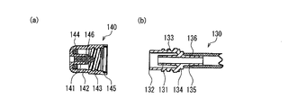
- FIGS. (A) of FIG. 13 shows the bag side connector 110 which is a female connector provided in a dialysate bag.
- FIG. 14 (b) shows a patient-side connector 130 configured as a male connector.
- 13B shows a bag-side connector cap 120
- FIG. 14A shows a patient-side connector cap 140.
- the bag-side connector 110 is composed of a double wall of a first annular luer part 111 and a first tip cylindrical part 112, and a first tube connecting part 116 is provided at the base end part 115 of the first annular luer part 111. Is provided.
- the first tube connection part 116 is connected to a tube 119 connected to the dialysate bag.
- a concave portion 117 is provided on the outer periphery of the base end portion 115, and a convex portion 118 is provided on the base end of the first tip cylindrical portion 112.
- the first tip cylindrical portion 112 is fitted to the base end portion 115 and can be rotated independently of the first tube connecting portion 116 and the first annular luer portion 111 via the concave portion 117 and the convex portion 118. Are combined.
- a female screw 113 is formed on the inner periphery of the first tip cylindrical portion 112.
- a sealing member 114 made of an elastic material is embedded in the inner peripheral surface near the tip of the first annular luer portion 111.
- the patient-side connector 130 includes a distal end cylindrical portion 132, a second annular luer portion 131 formed on the inside thereof, and a proximal end portion 134 having a second tube connection portion 135.
- the second tube connection part 135 is connected to the tube 136.
- the proximal end of the distal cylindrical portion 132 is coupled to the proximal end portion 134, and the distal cylindrical portion 132 extends long so as to cover the distal end of the second annular luer portion 131.
- a male screw 133 is formed to be screwed with the female screw 113 provided on the inner periphery of the distal end cylindrical portion 112 of the bag side connector.
- the outer periphery of the second annular luer part 131 can be in fluid-tight contact with a sealing member formed on the inner periphery of the tip end part of the first annular luer part 111 of the bag side connector.
- the female screw 113 and the male screw 133 are screwed together without twisting the tubes 119 and 136. Can be connected.
- the patient-side connector cap 140 includes a third inner cylinder 141, a third outer cylinder 142 formed concentrically around the third inner cylinder 141, and a plug 146 fitted to the tip of the third inner cylinder.
- On the inner periphery of the third outer cylinder 142 an internal thread 143 is formed that engages with the external thread 133 formed on the outer periphery of the distal end cylindrical portion 132 of the patient-side connector.
- a sealing member 145 made of an elastic material.
- a sterilization pad 144 containing a sterilizing agent is attached to the base end of the third inner cylinder 141.
- the stopper 146 is made of an elastic material, and is pressed against the second annular luer part 131 to seal liquid tightly.
- the sterilization pad 144 sterilizes the distal end cylindrical portion 132 when the patient side connector 130 is screwed to the patient side connector cap 140.
- the sealing member 145 seals the patient-side connector cap screwed with the patient-side connector so as to protect it from external contamination.
- the bag-side connector cap 120 has a fourth tip cylindrical portion 121 and a fourth cap base end portion 123.
- the fourth tip cylindrical portion 121 is formed with a male screw 122 that is screwed into a female screw 113 formed on the inner periphery of the first tip cylindrical portion 112.
- JP 59-500801 A Japanese Patent Laid-Open No. 8-1555025 Japanese Patent Laid-Open No. 8-215311
- the sterilizing agent that has exuded enters the internal flow path of the connector / conduit from the tip of the connector, or the sterilizing agent that leaks out leaks to the outside from the joint between the connector and the cap, contaminating the surroundings.
- the disinfectant may enter the patient through the internal flow path of the transfer tube, which may adversely affect the health of the PD patient.
- Such a problem is not limited to a connector for connecting a peritoneal dialysis tube, but is common to a connector used in a place where a liquid flow path needs to be connected, such as an infusion tube. More generally speaking, this is a problem common to medical fluid communication devices for forming a communication flow path by connecting members respectively attached to communication objects. More specifically, this is a problem common to configurations including a protective cap that can be attached to the coupling members separated from each other and has a sterilizing function.
- the present invention can sufficiently sterilize the distal end portion of the coupling member by attaching a protective cap that holds the sterilizing agent impregnated member in the back, and the distal end portion of the coupling member becomes the sterilizing agent impregnated member.
- An object of the present invention is to provide a medical fluid communication device capable of avoiding leakage of a bactericide due to contact.
- the medical liquid communication device of the present invention has a connecting member that forms a communication flow path between the communication objects by being attached to each other and connected to each other, and a sterilizing agent having a cylindrical shape with one end closed And a protective cap that holds the impregnated member in the innermost portion and can be attached to at least one of the coupling members separated from each other.
- an inner peripheral surface of the protective cap surrounds a distal end portion of the coupling member.
- the dimensional relationship between the coupling member and the protective cap is set so that the disinfectant-impregnated member is opposed to the distal end portion of the coupling member while maintaining a gap, and the opening end portion of the protective cap is formed.
- a sealing member mounted on an inner peripheral surface of the coupling member or an outer peripheral surface of a portion of the coupling member corresponding to an opening end of the protective cap, and the outer circumferential surface of the coupling member and the protection in a mounted state of the protective cap. The sealing member is pressed between the inner peripheral surfaces of the cap to form an airtight structure of the space.
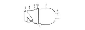
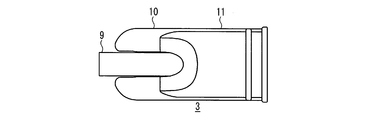
- FIG. 1A is a perspective view showing a male connector and a protective cap constituting the medical connector device in Embodiment 1 of the present invention in a separated state.
- FIG. 1B is a perspective view showing a state in which a protective cap is attached to the male connector in the medical connector device.
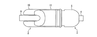
- FIG. 2A is a perspective view showing a female connector constituting the medical connector device.
- 2B is a perspective view showing a state where the male connector of FIG. 1A and the female connector of FIG. 2A are connected.
- FIG. 3A is a front view of the male connector of FIG. 1A.
- 3B is a right side view of the male connector of FIG. 3A.
- 3C is a cross-sectional view of the male connector of FIG. 3A.
- FIG. 4A is a front view of the protective cap of FIG. 1A.
- 4B is a right side view of the protective cap of FIG. 4A.
- 4C is a cross-sectional view taken along line AA in FIG. 4A.
- 4D is a cross-sectional view taken along line BB in FIG. 4B.
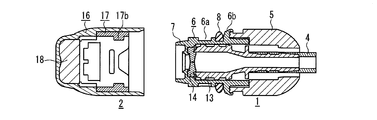
- FIG. 5A is a cross-sectional view showing the male connector and the protective cap in FIG. 1A.
- FIG. 5B is a front view showing the male connector and the protective cap in FIG. 1B.
- 5C is a cross-sectional view showing the internal structure of the male connector and the protective cap of FIG. 5B.
- 6A is a front view of the female connector of FIG. 2A.
- 6B is a left side view of the female connector of FIG. 6A.
- FIG. 6C is a right side view of the female connector of FIG. 6A.
- 6D is a cross-sectional view of the female connector of FIG. 6A.
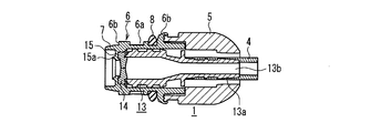
- FIG. 7A is a cross-sectional view showing a male connector and a female connector in an exploded state.
- FIG. 7B is a front view showing the male connector and the female connector in a connected state.
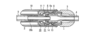
- FIG. 7C is a cross-sectional view of the male connector and the female connector of FIG. 7B.
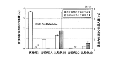
- FIG. 8 is a graph showing experimental results for demonstrating the effect of inhibiting the povidone iodine solution from exuding by the medical connector device according to the first embodiment of the present invention.
- FIG. 9A is a graph showing experimental results of accelerated storage for demonstrating sterilization ability retention performance by the medical connector device.
- FIG. 9B is a graph showing experimental results of room temperature storage for demonstrating the bactericidal ability retention performance of the medical connector device.
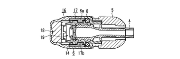
- FIG. 10A is a front view showing a connector and a protective cap that constitute the enteral nutrition connector device according to Embodiment 2 of the present invention.
- FIG. 10B is a cross-sectional view showing the internal structure of the protective cap.
- FIG. 10C is a front view showing a state where the protective cap is attached to the connector, with only the protective cap shown in cross section.
- FIG. 11A is a perspective view showing a mixed injection port and a protective cap that constitute the mixed injection port device according to Embodiment 3 of the present invention.
- FIG. 11B is a cross-sectional view showing the internal structure of the protective cap.
- FIG. 11A is a perspective view showing a mixed injection port and a protective cap that constitute the mixed injection port device according to Embodiment 3 of the present invention.
- FIG. 11B is a cross-sectional view showing the internal structure
- FIG. 12 is a perspective view showing another aspect of the mixed injection port.
- FIG. 13 is a cross-sectional view showing a configuration of a medical connector device of a conventional example.
- FIG. 14 is a cross-sectional view showing a configuration of a conventional medical connector device.
- the medical liquid communication device of the present invention can take the following modes based on the above configuration.
- one of the coupling members is a male connector and has a mounting portion connected to one of the communication targets at a rear end thereof, and the other of the coupling members is a female connector and a second connector at a rear end thereof. It can be set as the structure which has a mounting part connected with the said 2 communication object.
- the male connector has an inner cylinder whose lumen forms a flow channel for liquid circulation, and an outer cylinder whose inner diameter is larger than the outer diameter of the inner cylinder and is coaxially coupled to the outer side of the inner cylinder,
- the front end of the inner cylinder is located on the inner side of the front end of the outer cylinder, and the protective cap and the female connector can be attached to the outside of the outer cylinder.
- the male connector has a sealing valve that shields the lumen at the tip
- the female connector includes an inner cylinder in which the lumen forms a liquid flow path, and an inner diameter of the inner cylinder.
- An outer cylinder larger than an outer diameter and coaxially coupled to the outer side of the inner cylinder, and the male connector is inserted and connected to the inner side of the outer cylinder, and the male connector and the female connector Are connected, the tip of the inner cylinder of the female connector penetrates the sealing valve to open the flow path.
- a flange that is formed on the inner surface of the male connector and that has an opening smaller than the outer diameter of the sealing valve is preferably provided on the tip side of the sealing valve.
- the flange is provided with a rib extending toward the distal end side of the male connector.
- a configuration may be adopted in which a position restricting portion for restricting the moving position of the male connector toward the inner portion of the protective cap and securing the space is provided inside the protective cap.
- the position restricting portion is formed by an annular flange, and a contact portion having an outer diameter larger than the inner diameter of the annular flange is formed on the outer surface of the distal end portion of the male connector, and the male connector and the protective cap Can be configured such that the moving position of the male connector toward the inner part of the protective cap is restricted by the contact between the annular flange and the contact portion.
- the male connector and the protective cap are configured to be coupled by screwing, and the deepest position of the male connector and the protective cap that functions as the position restricting portion functions as the male connector.
- the moving position toward the back in the protective cap can be configured to be regulated.
- an inner member can be fitted inside the protective cap, and the disinfectant-impregnated member can be held at the innermost part of the protective cap by the inner member.
- the inner member may have a position restricting portion that restricts a moving position of the male connector toward the inner portion of the protective cap to secure the space.
- a reduced diameter part having a smaller diameter than the opening side is provided in the innermost part of the protective cap, and the disinfectant-impregnated member is disposed in the reduced diameter part.
- one of the communication objects includes a port of a medical container for injecting a nutrient or the like used for enteral nutrition, and the other includes a tube for connecting the medical container and a patient. It can be set as the structure which is an intestinal nutrition set.
- the connector for enteral nutrition provided at the port of the medical container constitutes one of the coupling members, and the connector provided at one end of the nutrition set and connected to the connector for enteral nutrition, It constitutes the other of the coupling members.
- One of the coupling members is a mixed injection port
- the mixed injection port includes a pedestal provided for communication, a disc-shaped valve that is supported on the pedestal from the lower surface side and has an insertion hole formed in the center, and A cover having a fitting hole for exposing an upper surface of a central portion of the valve and covering a peripheral edge of the valve from the upper surface side, and the other of the coupling members can be inserted into the mixed injection port, and a lumen thereof is a liquid flow path It can be set as the structure which is the insert which forms.
- the protective cap is configured to be attached to the mixed injection port.
- FIG. 1A is a perspective view showing a male connector 1 and a protective cap 2 constituting the medical connector device in an exploded state.
- FIG. 1B is a perspective view showing a state where the male connector 1 and the protective cap 2 of FIG. 1A are connected.
- FIG. 2A is a perspective view showing a female connector 3 constituting the medical connector device.
- 2B is a perspective view showing a state in which the male connector 1 shown in FIG. 1A and the female connector 3 shown in FIG. 2A are connected.
- the male connector 1 is used as a patient-side connector
- the female connector 3 is used as a bag-side connector provided in a dialysate bag.
- the male connector 1, the protective cap 2, and the female connector 3 are all made of resin.
- the male connector 1 is fitted with a tube 4 connected to a peritoneal catheter implanted in the abdominal cavity of the patient, for example, at the rear end.
- a grip portion 5 for operating the male connector 1 is provided at the front portion of the tube 4, and the distal end side forms a coupling portion with the protective cap 2 and the female connector 3.
- the coupling portion includes a cylindrical portion 6 and a tip small-diameter portion 7 formed to have a slightly smaller diameter than the cylindrical portion 6.
- a thread groove 6 a is formed on the outer peripheral surface of the cylindrical portion 6.
- a step is formed at the base end of the cylindrical portion 6 by the large-diameter portion 6b, and an elastic ring 8 that functions as a sealing member is mounted in contact with the large-diameter portion 6b.
- the protective cap 2 has a substantially cylindrical shape with one end closed, and can be attached to the outer end of the male connector 1 as shown in FIG. 1B. As will be described later with reference to the cross-sectional view, the protective cap 2 holds a disinfectant impregnated member impregnated with a disinfectant (for example, povidone iodine solution) in the innermost part. On the inner peripheral surface of the protective cap 2, an engagement protrusion (described later) for engaging the screw groove 6 a to fix the connection between the male connector 1 and the protective cap 2 when the male connector 1 is mounted. Is provided.
- the female connector 3 is connected to a circuit tip of a peritoneal dialysis device such as a twin bag, a Y set, or an APD. As shown in FIG. 2A, the tube 9 is attached to the rear end. A grip portion 10 for operating the female connector 3 is provided at the front portion of the tube 9, and the distal end side forms a coupling portion with the male connector 1. This coupling portion is formed inside the outer cylinder 11. On the inner peripheral surface of the outer cylinder 11, when connected to the male connector 1, there is an engagement protrusion 12 that engages with the thread groove 6 a and fixes the connection between the male connector 1 and the female connector 3. Is provided. The engaging protrusion provided on the inner peripheral surface of the protective cap 2 is the same as the engaging protrusion 12.
- the male connector 1 and the female connector 3 are connected and fixed by inserting the male connector 1 into the outer cylinder 11 and screwing the thread groove 6a and the engaging projection 12 together.
- the tubes 4 and 9 communicate with each other through a flow path that penetrates the lumens of the connectors 1 and 3.
- the female connector 3 is depicted as being horizontally reversed with respect to FIG. 2A.
- the feature of this embodiment is the configuration related to the combination of the male connector 1 and the protective cap 2 as described below. Accordingly, the structure of the male connector 1 and the protective cap 2 will be described in more detail with reference to FIGS. 3A to 5C. First, the structure of the protective cap 2 will be described.
- FIG. 3A is a front view of the male connector 1 of FIG. 1A
- FIG. 3B is a right side view of the male connector 1 of FIG. 3A
- FIG. 3C is a cross-sectional view of the male connector 1 of FIG.
- the male connector 1 is formed by being divided into a cylindrical portion 6, an inner member 13 attached to the lumen of the cylindrical portion 6, and a grip portion 5 connected to the rear portion of the cylindrical portion 6.
- the rear part of the inner member 13 extends inside the grip part 5 to form a tube connection part 13a, to which the tube 4 is connected.
- the inner cavity of the inner member 13 forms a flow path 13b.
- a sealing valve 14 (for example, a rubber slitted septum) is disposed at the distal end of the lumen of the cylindrical portion 6.
- a flange 15 that forms an opening smaller than the outer shape of the sealing valve 14 is provided on the inner peripheral surface of the tip of the cylindrical portion 6, and the sealing valve 14 is held between the tip of the inner member 13 and the flange 15.
- the flange 15 is provided with a rib 15a extending to the tip side.
- the sealing valve 14 has a function of sealing the flow path of the inner member 13 lumen when the male connector 1 and the female connector 3 are not connected. This prevents bacteria from entering the flow path from the outside of the male connector 1. In addition, the liquid is prevented from leaking from the flexible tube 4 side.
- the sealing valve 14 is effective to ensure the sealed state of the flow path of the inner member 13 lumen, but is not essential. Moreover, you may ensure a sealed state with another method.
- the flange 15 provided on the inner peripheral surface of the cylindrical portion 6 makes it easy to hold the sealing valve 14 in the flow path, and suppresses the finger contact with the sealing valve 14 from the distal end side of the male connector 1. Effect is obtained. By providing the rib 15a on the flange 15, the effect can be further improved.
- FIG. 4A is a front view of the protective cap 2
- FIG. 4B is a right side view of the protective cap 2 of FIG. 4A
- FIG. 4C is a cross-sectional view taken along line AA in FIG. 4A
- FIG. 4D is in FIG. It is sectional drawing along the BB line.
- the protective cap 2 is formed of a substantially cylindrical outer cylinder 16 whose one end is closed, and an inner member 17 fitted into the outer cylinder 16.
- a reduced diameter portion 16a having a smaller diameter than the opening side is provided, and a disinfectant-impregnated member 18 is disposed in the reduced diameter portion 16a.
- the disinfectant-impregnated member 18 is held at the innermost portion by the restriction of the inner end portion 17 a of the inner member 17.
- the sterilizing agent impregnated member 18 is easily held in the protective cap 2. Furthermore, the effect that the disinfectant-impregnated member 18 is difficult to touch the tip of the male connector 1 is also obtained.
- An engagement protrusion 17b is formed on the inner peripheral surface of the opening side end of the inner member 17.
- the connection between the male connector 1 and the protective cap 2 is formed by screwing the thread groove 6a on the outer peripheral surface of the male connector 1 and the engagement protrusion 17b. Further, the deepest position of the connection between the male connector 1 and the protective cap 2 is regulated by this screwing structure. Therefore, when the male connector and the protective cap are connected, the screwing structure functions as a position restricting element that restricts the moving position of the male connector 1 toward the inner part of the protective cap 2.
- annular flange 17c is formed on the inner peripheral surface of the intermediate portion of the inner member 17, and functions as a similar position restricting portion. That is, a contact portion 6b having an outer diameter larger than the inner diameter of the annular flange 17c is formed on the outer surface of the distal end portion of the male connector 1. Therefore, when the protective cap 2 is attached to the male connector 1, the movement position of the male connector 1 is restricted by the contact between the annular flange 17c and the contact portion 6b.
- the sterilizing agent-impregnated member 18 can be formed of a material such as a porous body or a fiber body, for example, a sponge.
- a sterilizing agent other than the povidone iodine solution may be used, but a povidone iodine solution is desirable in consideration of the influence on the human body.
- FIG. 5A is a sectional view showing the male connector 1 and the protective cap 2 in the exploded state of FIG. 1A
- FIG. 5B is a front view showing the male connector 1 and the protective cap 2 in the combined state of FIG. 1B
- FIG. These are sectional drawings of male connector 1 and protective cap 2 of Drawing 5B.
- the protective cap 2 is attached to the male connector 1 when the male connector 1 and the female connector 3 are not connected to protect the connector tip.
- the opening of the protective cap 2 is opposed to the tip of the male connector 1, and the male connector 1 is rotated while being pushed in.
- the protective cap 2 is attached to the tip of the male connector 1 through the engagement between the engaging protrusion 17b provided on the inner surface of the protective cap 2 and the thread groove 6a on the outer peripheral surface of the male connector 1. Fixed.
- the annular flange 17c formed on the inner peripheral surface of the inner member 17 of the protective cap functions as a position restricting portion, and depends on the deepest position of the male connector 1 and the protective cap 2 to be screwed together.
- the restriction structure functions as a position restriction part.
- a space 19 is formed between the periphery of the distal end portion of the male connector 1 and the inner surface of the protective cap 2 (see FIG. 5C). By forming this space, the sterilizing agent-impregnated member 18 held in the protective cap 2 is maintained in a state where it is opposed to the front end of the male connector 1 while maintaining a predetermined interval.
- the elastic ring 8 is pressed between the outer peripheral surface of the male connector 1 and the inner peripheral surface of the protective cap 3, whereby the airtightness of the space 19 is maintained. Therefore, iodine is sublimated from the sterilizing agent impregnated member 18 impregnated with the povidone iodine solution to fill the space 19, and a sufficient sterilizing effect on the tip of the male connector 1 sealed in the space 19 is obtained.
- the elastic ring 8 is fitted on the male connector 1, but the elastic ring 8 may be fitted inside the protective cap 3 in order to seal the space 19.
- the elastic ring 8 may be configured to be pressed from both the protective cap 3 and the male connector 1 when the protective cap 3 is attached to the male connector 1.
- the elastic ring 8 is externally fitted to the patient-side connector. This is because the protective cap and the connector on the dialysate side can be used only once, whereas the connector on the patient side is replaced once every six months, so that the cost of providing the elastic ring 8 can be reduced. This is not the case as long as the tube is for other purposes.
- the sterilizing agent impregnated member 18 is not in direct contact with the tip of the male connector 1, but a predetermined interval is provided between the sterilizing agent impregnated member 18 and the tip of the male connector 1. It was confirmed by the results of experiments described later that a sufficient bactericidal effect was obtained.
- the sterilized state of the distal end portion of the male connector can be easily maintained by attaching the protective cap 2 to the distal end side of the male connector 1.
- the sterilizing agent since a predetermined interval is provided between the sterilizing agent impregnated member 18 and the tip of the male connector 1, the sterilizing agent is exuded when the sterilizing agent impregnated member 18 receives a pressing force. Is avoided. Therefore, the sterilizing agent that has exuded enters the internal flow path of the connector / conduit from the tip of the connector, or the exuding sterilizing agent leaks to the outside from the joint between the connector and the cap, thereby contaminating the surroundings. Such inconvenience can be avoided.
- FIG. 6A is a front view of the female connector 3 in FIG. 2A
- FIG. 6B is a left side view of the female connector 3 in FIG. 6A
- FIG. 6C is a right side view thereof
- FIG. 6D is a female connector 3 in FIG. FIG.
- the female connector 3 has an inner cylinder 20 whose inner cavity forms a flow channel for liquid circulation, and an outer cylinder 11 whose inner diameter is larger than the outer diameter of the inner cylinder 20 and is coaxially coupled to the outside of the inner cylinder.
- a gripping portion 10 is formed at the rear end portion of the outer cylinder 11 and is coupled to the central portion of the inner cylinder 20.
- the outer cylinder 11 is open at the tip side, and an inner member 21 is inserted therein.
- Engagement protrusions 12 are formed on the inner peripheral surface of the inner member 21.
- the inner cylinder 20 includes an inner cylinder distal end portion 20 a that extends toward the opening inside the outer cylinder 11, and a tube connection portion 20 b that extends rearward of the outer cylinder 11 and is positioned inside the grip portion 10.
- FIGS. 7A to 7C are sectional views showing the male connector 1 and the female connector 3 in an exploded state
- FIG. 7B is a front view showing the male connector 1 and the female connector 3 in a connected state
- FIG. 2 is a cross-sectional view of the male connector 1 and the female connector 3 of FIG.
- the front end opening of the female connector 3 is opposed to the front end of the male connector 1, and the male connector 1 is rotated while being pushed in.
- the female connector 3 is attached to the tip of the male connector 1 through the engagement between the engagement protrusion 12 provided on the inner surface of the female connector 3 and the thread groove 6a on the outer peripheral surface of the male connector 1. Installed and fixed.
- the inner cylinder tip 20 a penetrates the male connector 1 while expanding the slit of the sealing valve 14 attached to the tip of the male connector 1. 1 is reached and the flow path is opened.
- the male connector 1 may have other forms for mounting the protective cap 2 as described above or for connection with the female connector 3. That is, the male connector is constituted by an inner cylinder whose inner cavity forms a liquid flow path, and an outer cylinder whose inner diameter is larger than the outer diameter of the inner cylinder and is coaxially coupled to the outer side of the inner cylinder.
- the tip of the inner cylinder is located on the inner side of the tip of the outer cylinder, and the protective cap and the female connector are attached to the outside of the outer cylinder. According to this configuration, even when the tip of the male connector is accidentally touched, it is possible to avoid touching the inner cylinder through which the liquid flows and to protect the inner cylinder. Since the bacteria attached to the outer cylinder can be sterilized as described above by covering the protective cap, the bacteria do not enter the flow path.
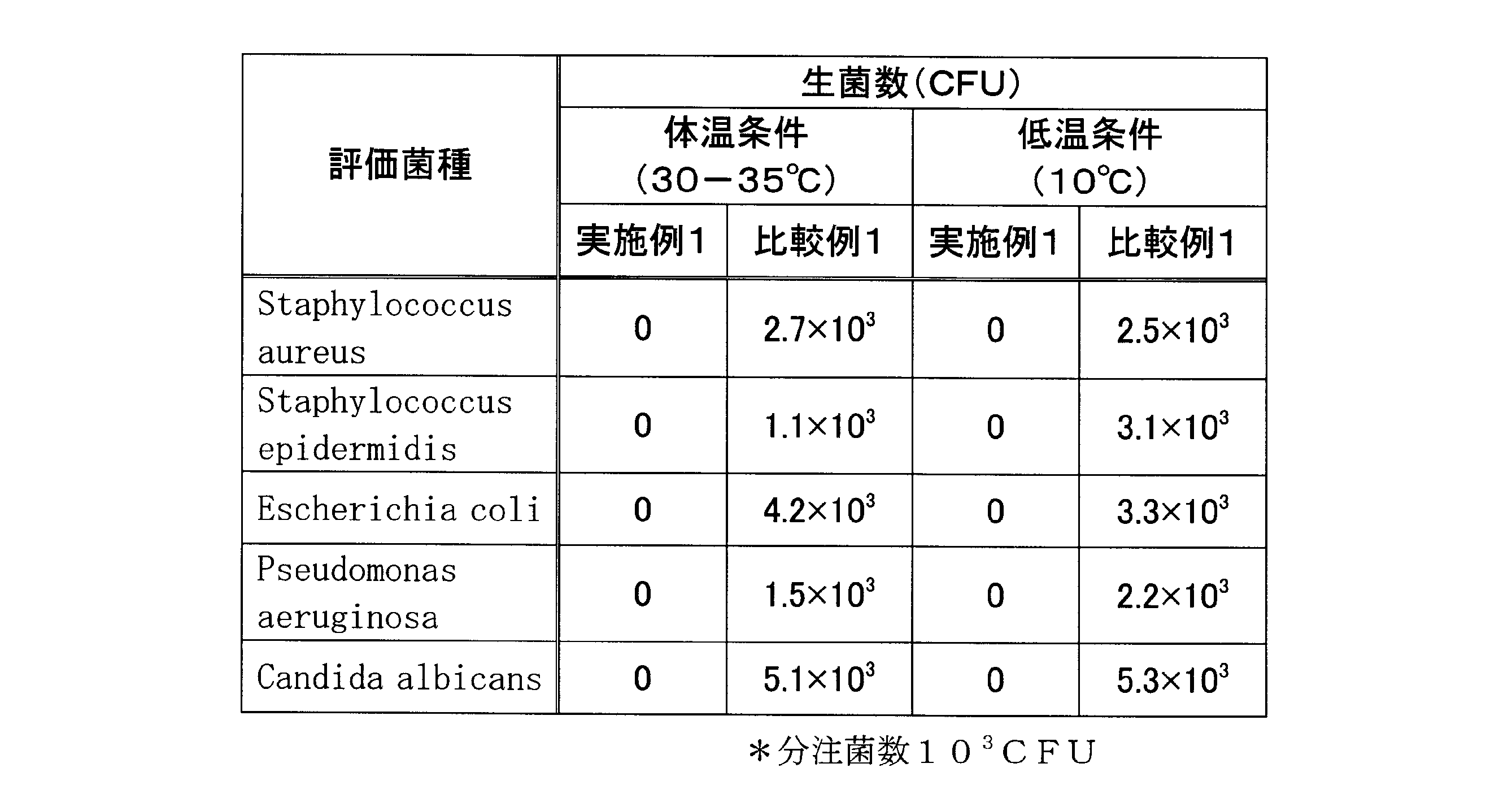
- the experimental method is as follows. First, five bacterial species of Staphylococcus aureus, Staphylococcus epidermidis, Escherichia coli, Pseudomonas aeruginosa, and Candida albicans were used as evaluation species. In the case of Staphylococcus spp., Physiological saline to which 0.01% of Tween 80 (PolyoxyethylenebitSorbitan Monoleate) was added was prepared, and in the case of other bacterial species, those dissolved in physiological saline were prepared.
- Tween 80 PolyoxyethylenebitSorbitan Monoleate
- 10 3 CFU / 20 ⁇ L of the bacterial solution was dispensed at the tip of the male connector 1, and after the protective cap 2 was attached, it was allowed to stand for 3 hours at a body temperature of 30-35 ° C. or a low temperature of 10 ° C. Thereafter, the protective cap 2 was removed, and the male connector 1 was placed in 10 mL of a rinse solution (FLUID D-ST solution / BioMerieux), stirred for 30 seconds, and then filtered through a filter having a diameter of 0.45 ⁇ m. After repeating this three times, this filter was placed on an SCD agar medium and cultured at 30-35 ° C., and the viable cell count was confirmed.
- a rinse solution FLUID D-ST solution / BioMerieux
- the fungicide-impregnated member 18 of the protective cap 2 is impregnated with a 10% povidone iodine solution.
- the fungicide-impregnated member 18 of the protective cap 2 is povidone-iodine solution. Instead, a material impregnated with physiological saline was used.
- the experimental method is as follows. That is, the protective cap 2 is attached to the tip of the male connector 1 and left for 4 hours, and then the protective cap 2 is removed. After the female connector 3 is connected to the male connector 1, 20 mL of ultrapure water is passed through the tube. Example 2 was obtained. With respect to this ultrapure water, effective iodine was quantified by a redox titration method using a 0.02N sodium thiosulfate solution as a titrant. The same test was performed on the conventional connector as Comparative Example 2 (all of the conventional products were in contact with the povidone iodine solution).
- Example 2 compared with Comparative Examples 2A to 2D, although the amount of effective iodine in the impregnated member was large, mixing into the liquid passage was not observed. I understand.
- Example 3 Verification of bactericidal ability retention performance
- the storage period during which bacteria present at the tip of the male connector 1 can be sterilized was confirmed.
- the experimental method is as follows. That is, the protective cap 2 is attached to the male connector 1, and after accelerated packaging at 40 ° C / 75% RH after packaging in aluminum packaging material, the water content and effective iodine content in the povidone iodine solution important for sterilization performance The change with time was evaluated. The water content was calculated by measuring the difference between the weight before storage and the weight after storage.
- the effective iodine amount For the effective iodine amount, after the protective cap 2 was immersed in 99.5% ethanol overnight, povidone iodine was extracted by thorough washing, and then a redox titration method using a 0.01 M sodium thiosulfate solution as a titrant. Quantitative determination of effective iodine. At this time, a calibration curve of the povidone iodine solution was prepared for each test, and the effective iodine amount of the specimen was calculated thereby. At the same time, the samples were stored in the same manner at room temperature, and the relationship between accelerated storage and storage at room temperature was confirmed from the moisture and effective iodine data.
- the bactericidal ability test was done by the same test as Experiment 1, and the bactericidal ability retention period was examined.
- the temperature condition was one condition of 30-35 ° C.
- the bacterial species evaluated was one bacterial species of Staphylococcus epidermidis.
- Comparative Example 3 a material impregnated with physiological saline instead of the povidone iodine solution impregnated in the impregnated member of the protective cap 2 was used.
- FIG. 9A The experimental results of accelerated storage are shown in FIG. 9A, and the results of room temperature storage experiments are shown in FIG. 9B. According to the results of this experiment, it can be seen from the comparison between the amount of water and the amount of effective iodine in each storage period that room temperature storage 12M (month) corresponds to accelerated storage 6W (weeks), and room temperature storage 24M corresponds to accelerated storage 12W. . Therefore, it was confirmed that accelerated storage corresponds to a storage period equivalent to eight times storage at room temperature.
- the accelerated storage 15W is comparable to the room temperature storage equivalent to two and a half years, so that the sterilization ability can be maintained for about two and a half years.
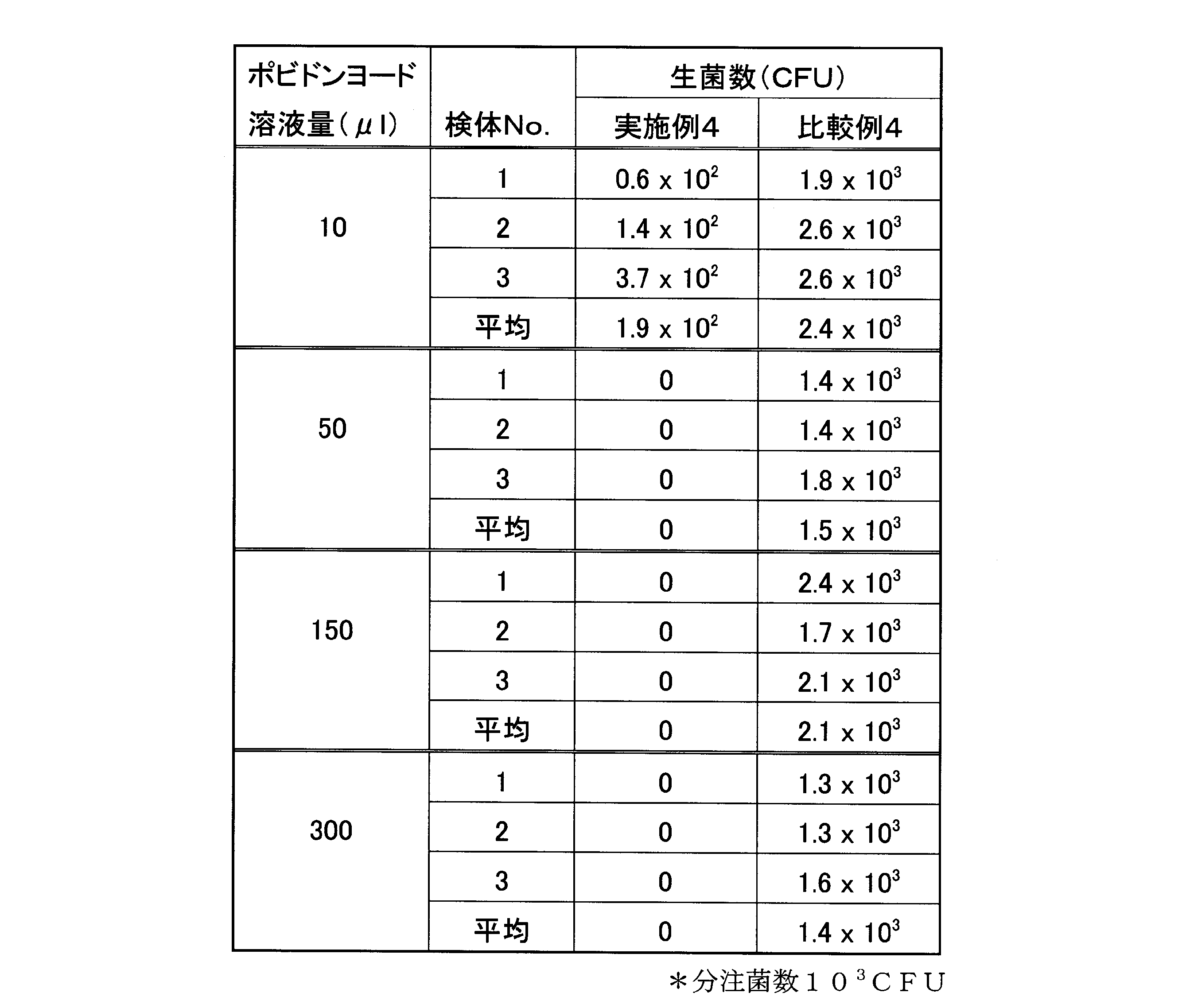
- Step 1 First, as a step 1, the following experiment was performed. That is, 10% povidone iodine solution was used as a bactericidal agent (Example 4), 10 3 CFU S. epidermidis was used as an evaluation bacterial species, and physiological saline was used for comparison with the evaluation bacterial species (Comparative Example). 4).
- the sponge was impregnated with 10 ⁇ l, 50 ⁇ l, 150 ⁇ l and 300 ⁇ l of povidone iodine solution, respectively.
- the sponge impregnated with the povidone iodine solution was attached to the plunger gasket of a 5 ml syringe, and the plunger was adjusted so that the space was 630 ml.
- the ratio of the povidone iodine solution necessary for killing the bacteria to the enclosed space volume was calculated.
- the spatial volume is 630 mm 3
- 10 3 CFU of S. epidermidis can be killed if 50% or more of 10% povidone iodine solution is present.
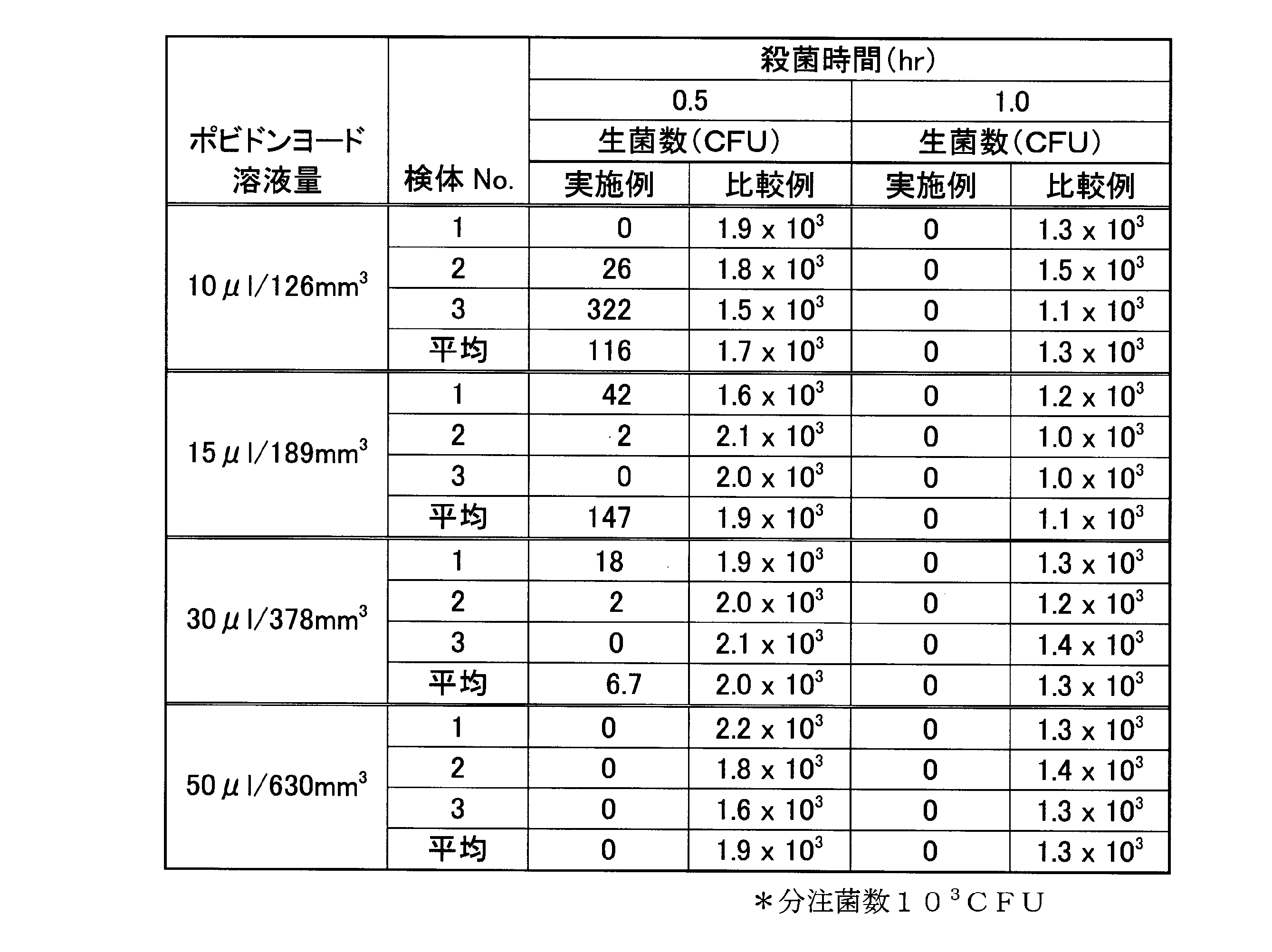
- Step 2 Next, as a step 2, the following experiment was performed. That is, sponges were impregnated with 10 ⁇ l, 50 ⁇ l, 150 ⁇ l, and 300 ⁇ l of povidone iodine solution, respectively. The foam impregnated with the povidone-iodine solution was attached to the plunger gasket of a 5 ml syringe, and the plunger was adjusted so that the space was each evaluation volume. Each evaluation volume was 630mm 3, 378mm 3, 189mm 3 , 126mm 3.
- the medical liquid communication device uses a connector device used for enteral nutrition as an application example.
- a connector device used for enteral nutrition As an application example.
- FIG. 10A to FIG. 10B the configuration of the connector device for enteral nutrition in the present embodiment will be described.
- liquids such as nutrients, liquid foods, or drugs are administered through a tube passed from the patient's nasal cavity to the stomach or duodenum.
- a nutrient or the like When administering a nutrient or the like, first, the nutrient or the like is injected into a medical container. Next, a connector attached to one end of an injection path set including a tube is connected to a port (liquid passing portion) of the medical container. Further, the medical container is suspended from the hanger with the port to which the injection path set is connected facing downward. With the medical container hung on the hanger, connect the connector attached to the other end of the infusion path set to the connector at the end of the tube attached to the patient. The product is administered to the patient.
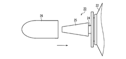
- FIG. 10A shows the port 23 of the medical container 22 to which the injection channel set is connected.
- the port 23 includes a tubular portion 24 in which a liquid passage hole for allowing a liquid substance to pass therethrough and a enteral nutrition connector 25 that forms the distal end of the tubular portion 24.
- the connector 25 is connected to a connector (not shown) at one end of the injection path set by a luer connection method. That is, the connector 25 and the connector attached to one end of the injection path set constitute the medical fluid communication device in the present embodiment.
- This enteral feeding connector device further includes a protective cap 26, and the protective cap 26 is attached to the connector 25 when the medical container 22 is not used.
- the internal structure of the protective cap 26 is shown in FIG. 10B.
- the protective cap 26 has a cylindrical shape with one end closed, and a disinfectant-impregnated member 27 is held in the innermost part.
- a sealing member 28 is attached to the inner peripheral surface of the opening end of the protective cap 26.
- the protective cap 26 when the protective cap 26 is attached to the connector 25, the protective cap 26 forms a space 29 surrounding the periphery of the tip of the connector 25, and the sterilizing agent impregnated member 27 maintains a predetermined interval so that the connector 25 Opposite the tip. Further, with the protective cap 26 attached to the connector 25, the sealing member 28 is pressed between the outer peripheral surface of the connector 25 and the inner peripheral surface of the protective cap 26, and an airtight structure of the space 29 is formed.
- the sterilized state of the portion can be easily maintained by attaching the protective cap 26 to the distal end portion of the connector 25.
- the sterilizing agent is prevented from exuding due to the pressing force of the sterilizing agent impregnating member 27. Accordingly, it is possible to avoid the inconvenience that the exfoliated sterilizing agent enters the internal flow path of the port 23 from the distal end portion of the connector 25 or the exuded sterilizing agent leaks to the outside and contaminates the surroundings. .
- the protective cap 26 is attached to the enteral nutrition connector 25 provided in the port 23 of the medical container 22, but the protective cap is attached to the connector at the end of the tube attached to the patient.
- the same effect can also be obtained by configuring as described above.
- the medical liquid communication device in the third embodiment is an application example of a medical mixed injection port device.
- FIGS. 11A to 11B the configuration of the co-injection port apparatus according to the present embodiment will be described.
- the medical co-infusion port is used to administer medicinal solution, etc. to the patient, to mix medicinal solution different from the main medicinal solution into the medicinal solution supply channel, or to sample the liquid flowing in the medicinal solution channel, etc. It is done. Therefore, the mixed injection port is configured such that the above operation can be performed by inserting an insert having a sharp tip into an insertion hole formed in the valve.
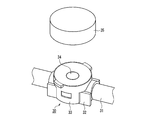
- the mixed injection port 30 shown in FIG. 11A is mounted in the middle of the tube 31 to be communicated.
- the communication target is not limited to the tube, and may be any other form.
- a pedestal 32 is provided on the tube 31, and a cover 34 is attached to the pedestal 32.
- the pedestal 32 and the cover 33 hold a disc-like valve 34 having an insertion hole formed in the center. That is, the valve 34 is supported by the pedestal 32, the cover 33 is in contact with the valve 34, and the valve 34 is sandwiched between the pedestal 32 and the cover 33.
- the cover 34 has a fitting hole that exposes the upper surface of the central portion of the valve 34 at the central portion.
- the pedestal 32 has a through hole that communicates with the lumen of the tube 31.
- the lumen of the insert communicates with the lumen of the tube 31.
- liquid can be injected and / or collected, and when the lure is removed from the valve 34, the valve 34 closes due to its elasticity. That is, the co-infusion port device composed of the co-infusion port 30 and the insert constitutes the medical liquid communication device in the present embodiment.
- the mixed injection port device further includes a protective cap 35, and the protective cap 35 is attached to the mixed injection port 30 when the mixed injection port 30 is not used.
- FIG. 11B shows the internal structure of the protective cap 35.
- the protective cap 35 has a cylindrical shape with one end closed, and a disinfectant-impregnated member 36 is held at the innermost part.
- a sealing member 37 is attached to the inner peripheral surface of the opening end of the protective cap 35.
- the protective cap 35 When the protective cap 35 is attached to the mixed injection port 30, the protective cap 35 forms a space surrounding the periphery of the upper end of the mixed injection port 30, and the disinfectant impregnating member 36 is opposed to the upper end of the mixed injection port 30 while maintaining a predetermined interval. . Further, the sealing member 37 is pressed between the outer peripheral surface of the mixed injection port 30 and the inner peripheral surface of the protective cap 35 in a state where the protective cap 35 is attached to the mixed injection port 30, thereby forming an airtight structure of the space.
- the sterilized state of the portion can be easily maintained by attaching the protective cap 35 to the upper end portion of the mixed injection port 30.
- a predetermined space is provided between the sterilizing agent impregnating member 36 and the tip of the co-injecting port 30, exudation of the sterilizing agent due to the pressing force of the sterilizing agent impregnating member 36 is avoided. Therefore, it is possible to avoid the inconvenience that the exfoliated sterilizing agent enters the internal flow path of the tube 31 from the distal end portion of the mixed injection port 30, or the exuded sterilizing agent leaks to the outside and contaminates the surroundings. it can.
- FIG. 12 is a perspective view showing a mixed injection port device according to another aspect of the present embodiment. Elements similar to those of the mixed injection port apparatus shown in FIG. 11A are denoted by the same reference numerals, and description thereof will not be repeated.
- the mixed injection port 30 is attached to one end of the tube 31. Even in such an embodiment, the same effect as described above can be obtained by using the same protective cap as described above.
- the distal end portion of the coupling member can be sufficiently sterilized by attaching the protective cap that holds the sterilizing agent-impregnated member in the back, and the distal end of the coupling member Since the leakage of the sterilizing agent due to the contact of the part with the sterilizing agent-impregnated member is avoided, it is useful for a connector device or the like for channel connection in peritoneal dialysis or infusion.
Abstract
Description
本発明の実施の形態1における医療用液体連通装置は、腹膜透析におけるチューブ接続用の医療用コネクタ装置を適用例としたものである。まず、図1A~図2Bを参照して、本実施の形態の医療用コネクタ装置の概要について説明する。図1Aは、この医療用コネクタ装置を構成する雄型コネクタ1と保護キャップ2を、分解した状態で示す斜視図である。図1Bは、図1Aの雄型コネクタ1と保護キャップ2が接続された状態を示す斜視図である。図2Aは、この医療用コネクタ装置を構成する雌型コネクタ3を示す斜視図である。図2Bは、図1Aに示した雄型コネクタ1と、図2Aに示した雌型コネクタ3が接続された状態を示す斜視図である。 (Embodiment 1)
The medical liquid communication device according to
ポビドンヨード溶液が、雄型コネクタ1の先端部に非接触の状態で対向する構成により、雄型コネクタ1の先端部に存在する菌を殺菌する作用が得られることについて検証した。 [Experiment 1: Verification of bactericidal activity]
It was verified that the povidone-iodine solution is capable of sterilizing bacteria present at the tip of the
保護キャップ2を装着し外した後に、コネクタ導管部分に通液を行った場合に、保護キャップ2の殺菌剤含浸部材18中のポビドンヨード溶液が通液内に混入するかどうか確認した。 [Experiment 2: Povidone iodine solution contamination test]
After the
雄型コネクタ1の先端部に存在する菌を殺菌可能な保存期間について確認した。実験方法は以下のとおりである。すなわち、雄型コネクタ1に保護キャップ2を装着し、アルミ包材に包装後40℃/75%RHの条件下で加速保管を行い、殺菌能に重要なポビドンヨード溶液中の水分量及び有効ヨウ素量の経時変化の評価を行った。水分量については、保管前重量と保管後重量との差を測定することで算出した。 [Experiment 3: Verification of bactericidal ability retention performance]
The storage period during which bacteria present at the tip of the

密閉空間内での殺菌剤濃度による非接触殺菌能の変化について調べる実験を行った。 [Experiment 4: Verification of relationship between bactericide concentration in closed space and non-contact bactericidal ability]
An experiment was conducted to investigate the change of non-contact sterilization ability due to the concentration of bactericide in a sealed space.
先ず、ステップ1として以下の実験を行なった。すなわち、殺菌剤として10%のポビドンヨード溶液を用い(実施例4)、評価菌種として103CFUのS. epidermidisを用い、評価菌種との比較用に生理食塩水をそれぞれ用いた(比較例4)。 (1)
First, as a
次に、ステップ2として以下の実験を行なった。すなわち、スポンジに、10μl、50μl、150μl、300μlのポビドンヨード溶液をそれぞれ含浸させた。ポビドンヨード溶液が含浸したフォームを5mlシリンジのプランジャーのガスケットに装着し、空間が各評価体積となるようにプランジャーを調節した。各評価体積は、630mm3、378mm3、189mm3、126mm3とした。 (2)
Next, as a
本発明の実施の形態2における医療用液体連通装置は、経腸栄養法に用いられるコネクタ装置を適用例とするものである。図10A~図10Bを参照して、本実施の形態における経腸栄養用コネクタ装置の構成について説明する。 (Embodiment 2)
The medical liquid communication device according to the second embodiment of the present invention uses a connector device used for enteral nutrition as an application example. With reference to FIG. 10A to FIG. 10B, the configuration of the connector device for enteral nutrition in the present embodiment will be described.
実施の形態3における医療用液体連通装置は、医療用混注ポート装置を適用例としたものである。図11A~図11Bを参照して、本実施の形態における混注ポート装置の構成について説明する。 (Embodiment 3)
The medical liquid communication device in the third embodiment is an application example of a medical mixed injection port device. With reference to FIGS. 11A to 11B, the configuration of the co-injection port apparatus according to the present embodiment will be described.
2、26、35 保護キャップ
3 雌型コネクタ
4、9、31 チューブ
5、10 把持部
6 円筒部
6a ねじ溝
6b 当接部
7 先端小径部
8 弾性リング
11、16 外筒
12、17b 係合突起
13、17、21 インナー部材
13a チューブ接続部
13b 流路
14 密閉弁
15 フランジ
15a リブ
16a 縮径部
17a 内端部
17c 環状フランジ
18、27、36 殺菌剤含浸部材
19、29 空間
20 内筒
20a 内筒先端部
20b チューブ接続部
21 インナー部材
22 医療用容器
23 ポート
24 管状部
25 経腸栄養用コネクタ
28、37 封止部材
30 混注ポート
32 台座
33 カバー
34 弁 DESCRIPTION OF
Claims (14)
- 連通対象に各々装着され互いに結合されることにより前記連通対象間の連通流路を形成する結合部材と、
一端が閉塞された筒形状を有して殺菌剤含浸部材を最奥部に保持し、互いに分離された状態の前記結合部材の少なくとも一方に装着可能な保護キャップとを備え、
前記保護キャップが前記結合部材に装着された状態において、前記保護キャップの内周面は前記結合部材の先端部を包囲する空間を形成し、前記殺菌剤含浸部材が間隔を保持して前記結合部材の先端部と対向するように、前記結合部材と前記保護キャップの相互の寸法関係が設定され、
前記保護キャップの開口端部の内周面または前記結合部材における前記保護キャップの開口端部に対応する部位の外周面に装着された封止部材を備え、前記保護キャップの装着状態で、前記結合部材の外周面と前記保護キャップの内周面間に前記封止部材が押圧されて前記空間の気密構造が形成されることを特徴とする医療用液体連通装置。 A coupling member that is mounted on each communication target and coupled to each other to form a communication channel between the communication targets;
A protective cap that has a cylindrical shape with one end closed, holds the disinfectant-impregnated member at the innermost part, and can be attached to at least one of the coupling members in a state separated from each other;
In a state in which the protective cap is mounted on the coupling member, an inner peripheral surface of the protective cap forms a space surrounding a front end portion of the coupling member, and the sterilizing agent-impregnated member maintains a gap so that the coupling member The mutual dimensional relationship between the coupling member and the protective cap is set so as to face the tip portion of
A sealing member mounted on an inner peripheral surface of the opening end portion of the protective cap or an outer peripheral surface of a portion of the coupling member corresponding to the opening end portion of the protective cap; The medical fluid communication device, wherein the sealing member is pressed between an outer peripheral surface of the member and an inner peripheral surface of the protective cap to form an airtight structure of the space. - 前記結合部材の一方は雄型コネクタであり、その後端部に前記連通対象の一方と連結される装着部を有し、
前記結合部材の他方は雌型コネクタであり、その後端部に第2の前記連通対象と連結される装着部を有する請求項1に記載の医療用液体連通装置。 One of the coupling members is a male connector, and has a mounting portion connected to one of the communication targets at a rear end portion thereof.
The medical fluid communication device according to claim 1, wherein the other of the coupling members is a female connector, and has a mounting portion connected to the second communication target at a rear end portion thereof. - 前記雄型コネクタは、内腔が液体流通用流路を形成する内筒と、内径が前記内筒の外径よりも大きく前記内筒の外側に同軸に結合された外筒とを有し、
前記内筒の先端が前記外筒の先端よりも内部側に位置しており、
前記保護キャップ及び前記雌型コネクタは、前記外筒の外側に装着される請求項2に記載の医療用液体連通装置。 The male connector has an inner cylinder whose lumen forms a flow channel for liquid circulation, and an outer cylinder whose inner diameter is larger than the outer diameter of the inner cylinder and is coaxially coupled to the outer side of the inner cylinder,
The tip of the inner cylinder is located on the inner side of the tip of the outer cylinder,
The medical fluid communication device according to claim 2, wherein the protective cap and the female connector are attached to the outside of the outer cylinder. - 前記雄型コネクタは、先端部に内腔を遮蔽する密閉弁を有し、
前記雌型コネクタは、内腔が液体流通用流路を形成する内筒と、内径が前記内筒の外径よりも大きく前記内筒の外側に同軸に結合された外筒とを有して、前記外筒の内側に前記雄型コネクタが挿入されて接続され、
前記雄型コネクタと前記雌型コネクタとが接続されたとき、前記雌型コネクタの前記内筒の先端が前記密閉弁を貫通して流路が開通する請求項2に記載の医療用液体連通装置。 The male connector has a sealing valve that shields the lumen at the tip,
The female connector has an inner cylinder whose inner cavity forms a liquid flow path, and an outer cylinder whose inner diameter is larger than the outer diameter of the inner cylinder and is coaxially coupled to the outer side of the inner cylinder. , The male connector is inserted and connected to the inside of the outer cylinder,
The medical fluid communication device according to claim 2, wherein when the male connector and the female connector are connected, a tip of the inner cylinder of the female connector penetrates the sealing valve and a flow path is opened. . - 前記密閉弁よりも先端側に、前記雄型コネクタの内面に形成され前記密閉弁の外径よりも小さい開口を形成するフランジが設けられた請求項4に記載の医療用液体連通装置。 5. The medical fluid communication device according to claim 4, wherein a flange formed on an inner surface of the male connector and having an opening smaller than an outer diameter of the sealing valve is provided on a tip side of the sealing valve.
- 前記フランジに、前記雄型コネクタの先端側に延びるリブが設けられた請求項5に記載の医療用液体連通装置。 The medical fluid communication device according to claim 5, wherein the flange is provided with a rib extending toward a distal end side of the male connector.
- 前記保護キャップの内部に、前記雄型コネクタの前記保護キャップ内の奥部に向かう移動位置を規制して前記空間を確保する位置規制部が設けられた請求項2~6のいずれか1項に記載の医療用液体連通装置。 7. The position restricting portion that secures the space by restricting a movement position of the male connector toward the inner portion of the protective cap in the protective cap, according to any one of claims 2 to 6. The medical fluid communication device described.
- 前記位置規制部は環状フランジにより形成され、前記雄型コネクタの先端部外面には前記環状フランジの内径よりも大きい外径を有する当接部が形成され、
前記雄型コネクタと前記保護キャップとが接続されたとき、前記環状フランジと前記当接部の接触により前記雄型コネクタの前記保護キャップ内の奥部に向かう移動位置が規制される請求項7に記載の医療用液体連通装置。 The position restricting portion is formed by an annular flange, and a contact portion having an outer diameter larger than the inner diameter of the annular flange is formed on the outer surface of the distal end portion of the male connector.
8. When the male connector and the protective cap are connected, the movement position of the male connector toward the inner portion of the protective cap is restricted by the contact between the annular flange and the contact portion. The medical fluid communication device described. - 前記雄型コネクタと前記保護キャップとは螺合により結合するように構成され、
前記雄型コネクタと前記保護キャップの前記螺合の最深位置が前記位置規制部として機能し、前記雄型コネクタの前記保護キャップ内の奥部に向かう移動位置が規制される請求項7に記載の医療用液体連通装置。 The male connector and the protective cap are configured to be coupled by screwing,
The deepest position of the said screw connection of the said male connector and the said protective cap functions as the said position control part, The movement position toward the back | inner part in the said protective cap of the said male connector is controlled. Medical fluid communication device. - 前記保護キャップの内部にインナー部材が嵌入され、前記インナー部材により前記殺菌剤含浸部材が前記保護キャップの最奥部に保持されている請求項2記載の医療用液体連通装置。 The medical fluid communication device according to claim 2, wherein an inner member is fitted into the protective cap, and the sterilizing agent-impregnated member is held at the innermost part of the protective cap by the inner member.
- 前記インナー部材は、前記雄型コネクタの前記保護キャップ内の奥部に向かう移動位置を規制して前記空間を確保する位置規制部を有する請求項10に記載の医療用液体連通装置。 The medical fluid communication device according to claim 10, wherein the inner member has a position restricting portion that restricts a moving position of the male connector toward the inner portion of the protective cap to secure the space.
- 前記保護キャップの最奥部に、開口部側よりも小径になった縮径部が設けられ、前記縮径部に前記殺菌剤含浸部材が配置されている請求項2に記載の医療用液体連通装置。 The medical fluid communication according to claim 2, wherein a diameter-reduced portion having a smaller diameter than the opening side is provided at the innermost portion of the protective cap, and the bactericide-impregnated member is disposed in the diameter-reduced portion. apparatus.
- 前記連通対象の一方は、経腸栄養法に用いられる栄養剤等を注入するための医療用容器のポート、他方は、前記医療用容器と患者の間を接続するためのチューブを含む経腸栄養セットであり、
前記医療用容器のポートに設けられた経腸栄養用コネクタが前記結合部材の一方を構成し、
前記栄養セットの一端に設けられ前記経腸栄養用コネクタと接続されるコネクタが、前記結合部材の他方を構成する請求項1に記載の医療用液体連通装置。 One of the communication objects is a port of a medical container for injecting a nutrient used in enteral nutrition, and the other is an enteral nutrition including a tube for connecting the medical container and a patient. Set,
The connector for enteral nutrition provided at the port of the medical container constitutes one of the coupling members,
The medical fluid communication device according to claim 1, wherein a connector provided at one end of the nutrition set and connected to the enteral nutrition connector constitutes the other of the coupling members. - 前記結合部材の一方は混注ポートであり、前記混注ポートは、連通対象に設けられる台座と、前記台座に下面側から支持され中央部に挿入孔が形成されたディスク状の弁と、前記弁の中央部の上面を露出させる嵌合孔を有し前記弁の周縁を上面側から覆うカバーとを含み、
前記結合部材の他方は、前記混注ポートに挿入可能でその内腔が液体流路を形成している挿入体であり、
前記保護キャップは、前記混注ポートに対して装着されるように構成された請求項1に記載の医療用液体連通装置。 One of the coupling members is a mixed injection port, and the mixed injection port includes a pedestal provided for communication, a disc-like valve supported on the pedestal from the lower surface side and having an insertion hole formed in a central portion thereof, A cover that has a fitting hole that exposes the upper surface of the central portion and covers the periphery of the valve from the upper surface side;
The other of the coupling members is an insert that can be inserted into the co-injection port and the lumen forms a liquid flow path,
The medical fluid communication device according to claim 1, wherein the protective cap is configured to be attached to the mixed injection port.
Priority Applications (5)
| Application Number | Priority Date | Filing Date | Title |
|---|---|---|---|
| CN201080025872.3A CN102802692B (en) | 2009-06-12 | 2010-06-10 | Medical device for liquid communication |
| KR1020117027451A KR101292899B1 (en) | 2009-06-12 | 2010-06-10 | Medical device for forming liquid communication path |
| MX2011013361A MX2011013361A (en) | 2009-06-12 | 2010-06-10 | Medical device for forming liquid communication path. |
| JP2011518576A JP5278548B2 (en) | 2009-06-12 | 2010-06-10 | Medical fluid communication device |
| HK13105560.4A HK1178471A1 (en) | 2009-06-12 | 2013-05-09 | Medical device for forming liquid communication path |
Applications Claiming Priority (2)
| Application Number | Priority Date | Filing Date | Title |
|---|---|---|---|
| JP2009-141152 | 2009-06-12 | ||
| JP2009141152 | 2009-06-12 |
Publications (1)
| Publication Number | Publication Date |
|---|---|
| WO2010143693A1 true WO2010143693A1 (en) | 2010-12-16 |
Family
ID=43308948
Family Applications (1)
| Application Number | Title | Priority Date | Filing Date |
|---|---|---|---|
| PCT/JP2010/059860 WO2010143693A1 (en) | 2009-06-12 | 2010-06-10 | Medical device for forming liquid communication path |
Country Status (7)
| Country | Link |
|---|---|
| JP (1) | JP5278548B2 (en) |
| KR (1) | KR101292899B1 (en) |
| CN (1) | CN102802692B (en) |
| CO (1) | CO6430438A2 (en) |
| HK (1) | HK1178471A1 (en) |
| MX (1) | MX2011013361A (en) |
| WO (1) | WO2010143693A1 (en) |
Cited By (15)
| Publication number | Priority date | Publication date | Assignee | Title |
|---|---|---|---|---|
| JP2013042952A (en) * | 2011-08-24 | 2013-03-04 | Jms Co Ltd | Cap and connector system |
| WO2014126867A1 (en) * | 2013-02-13 | 2014-08-21 | Becton, Dickinson And Company | Disinfection cap for disinfecting a male luer end of an infusion therapy device |
| US9283368B2 (en) | 2005-11-17 | 2016-03-15 | Becton, Dickinson And Company | Patient fluid line access valve antimicrobial cap/cleaner |
| US9283369B2 (en) | 2014-02-20 | 2016-03-15 | Becton, Dickinson And Company | IV access port cap for providing antimicrobial protection |
| US9399125B2 (en) | 2013-02-13 | 2016-07-26 | Becton, Dickinson And Company | Needleless connector and access port disinfection cleaner and antimicrobial protection cap |
| US9480833B2 (en) | 2010-07-15 | 2016-11-01 | Becton, Dickinson And Company | Antimicrobial IV access cap |
| US9861733B2 (en) | 2012-03-23 | 2018-01-09 | Nxstage Medical Inc. | Peritoneal dialysis systems, devices, and methods |
| US9907897B2 (en) | 2011-03-23 | 2018-03-06 | Nxstage Medical, Inc. | Peritoneal dialysis systems, devices, and methods |
| JP2020146096A (en) * | 2019-03-11 | 2020-09-17 | テルモ株式会社 | Pedestal and protective cap assembly |
| JP2020146097A (en) * | 2019-03-11 | 2020-09-17 | テルモ株式会社 | Pedestal and protective cap assembly |
| JP2021045473A (en) * | 2019-09-20 | 2021-03-25 | 株式会社ジェイ・エム・エス | Connection structure for medical port |
| CN113080915A (en) * | 2021-05-08 | 2021-07-09 | 中国人民解放军陆军特色医学中心 | Desk-top sphygmomanometer and disinfection system thereof |
| US11207454B2 (en) | 2018-02-28 | 2021-12-28 | Nxstage Medical, Inc. | Fluid preparation and treatment devices methods and systems |
| EP4144401A3 (en) * | 2014-04-23 | 2023-05-24 | Becton, Dickinson and Company | Antimicrobial caps for medical connectors |
| US11674614B2 (en) | 2020-10-09 | 2023-06-13 | Icu Medical, Inc. | Fluid transfer device and method of use for same |
Families Citing this family (6)
| Publication number | Priority date | Publication date | Assignee | Title |
|---|---|---|---|---|
| USD820441S1 (en) | 2016-06-13 | 2018-06-12 | Integra Lifesciences Nr Ireland Limited | Surgical handpiece nosecone |
| CN106175881A (en) * | 2016-08-30 | 2016-12-07 | 苏州品诺维新医疗科技有限公司 | A kind of fluid coupling and installation method, operation technique system |
| JP6975227B2 (en) * | 2016-09-15 | 2021-12-01 | インテグラ ライフサイエンシーズ エンタープライジーズ, エルエルエルピー | Connector for surgical handpiece |
| JP6841730B2 (en) * | 2017-06-28 | 2021-03-10 | テルモ株式会社 | Holder |
| KR101982004B1 (en) * | 2017-08-28 | 2019-05-24 | 김은자 | Medicine container and infusion solution container coupled with medicine container |
| JP7038535B2 (en) * | 2017-12-11 | 2022-03-18 | テルモ株式会社 | cap |
Citations (3)
| Publication number | Priority date | Publication date | Assignee | Title |
|---|---|---|---|---|
| JPH0531178A (en) * | 1991-08-02 | 1993-02-09 | Terumo Corp | Medical connector and cap device |
| JP2001309973A (en) * | 2000-05-01 | 2001-11-06 | Jms Co Ltd | Connector cap |
| WO2005011798A1 (en) * | 2003-07-31 | 2005-02-10 | Jms Co., Ltd. | Connector system for medical use |
Family Cites Families (2)
| Publication number | Priority date | Publication date | Assignee | Title |
|---|---|---|---|---|
| US5242425A (en) * | 1991-11-14 | 1993-09-07 | Gish Biomedical, Inc. | Antiseptic catheter coupling septum |
| US8740864B2 (en) * | 2005-11-17 | 2014-06-03 | Becton, Dickinson And Company | Patient fluid line access valve antimicrobial cap/cleaner |
-
2010
- 2010-06-10 MX MX2011013361A patent/MX2011013361A/en active IP Right Grant
- 2010-06-10 KR KR1020117027451A patent/KR101292899B1/en active IP Right Grant
- 2010-06-10 WO PCT/JP2010/059860 patent/WO2010143693A1/en active Application Filing
- 2010-06-10 JP JP2011518576A patent/JP5278548B2/en active Active
- 2010-06-10 CN CN201080025872.3A patent/CN102802692B/en active Active
-
2011
- 2011-12-16 CO CO11173943A patent/CO6430438A2/en not_active Application Discontinuation
-
2013
- 2013-05-09 HK HK13105560.4A patent/HK1178471A1/en unknown
Patent Citations (3)
| Publication number | Priority date | Publication date | Assignee | Title |
|---|---|---|---|---|
| JPH0531178A (en) * | 1991-08-02 | 1993-02-09 | Terumo Corp | Medical connector and cap device |
| JP2001309973A (en) * | 2000-05-01 | 2001-11-06 | Jms Co Ltd | Connector cap |
| WO2005011798A1 (en) * | 2003-07-31 | 2005-02-10 | Jms Co., Ltd. | Connector system for medical use |
Cited By (49)
| Publication number | Priority date | Publication date | Assignee | Title |
|---|---|---|---|---|
| US10159828B2 (en) | 2005-11-17 | 2018-12-25 | Becton, Dickinson And Company | Patient fluid line access valve antimicrobial cap/cleaner |
| US11331464B2 (en) | 2005-11-17 | 2022-05-17 | Becton, Dickinson And Company | Patient fluid line access valve antimicrobial cap/cleaner |
| US10406343B2 (en) | 2005-11-17 | 2019-09-10 | Becton, Dickinson And Company | Patient fluid line access valve antimicrobial cap/cleaner |
| US9283368B2 (en) | 2005-11-17 | 2016-03-15 | Becton, Dickinson And Company | Patient fluid line access valve antimicrobial cap/cleaner |
| US10335584B2 (en) | 2005-11-17 | 2019-07-02 | Becton, Dickinson And Company | Patient fluid line access valve antimicrobial cap/cleaner |
| US9283367B2 (en) | 2005-11-17 | 2016-03-15 | Becton, Dickinson And Company | Patient fluid line access valve antimicrobial cap/cleaner |
| US10335585B2 (en) | 2005-11-17 | 2019-07-02 | Becton, Dickinson And Company | Patient fluid line access valve antimicrobial cap/cleaner |
| US9480833B2 (en) | 2010-07-15 | 2016-11-01 | Becton, Dickinson And Company | Antimicrobial IV access cap |
| US10328252B2 (en) | 2010-07-15 | 2019-06-25 | Becton, Dickinson And Company | Antimicrobial IV access cap |
| US10610630B2 (en) | 2011-03-23 | 2020-04-07 | Nxstage Medical, Inc. | Peritoneal dialysis systems, devices, and methods |
| US11135348B2 (en) | 2011-03-23 | 2021-10-05 | Nxstage Medical, Inc. | Peritoneal dialysis systems, devices, and methods |
| US10046100B2 (en) | 2011-03-23 | 2018-08-14 | Nxstage Medical, Inc. | Peritoneal dialysis systems, devices, and methods |
| US11433169B2 (en) | 2011-03-23 | 2022-09-06 | Nxstage Medical, Inc. | Dialysis systems, devices, and methods |
| US10898630B2 (en) | 2011-03-23 | 2021-01-26 | Nxstage Medical, Inc. | Peritoneal dialysis systems, devices, and methods |
| US11433170B2 (en) | 2011-03-23 | 2022-09-06 | Nxstage Medical, Inc. | Dialysis systems, devices, and methods |
| US11690941B2 (en) | 2011-03-23 | 2023-07-04 | Nxstage Medical, Inc. | Peritoneal dialysis systems, devices, and methods |
| US11224684B2 (en) | 2011-03-23 | 2022-01-18 | Nxstage Medical, Inc. | Peritoneal dialysis systems, devices, and methods |
| US9907897B2 (en) | 2011-03-23 | 2018-03-06 | Nxstage Medical, Inc. | Peritoneal dialysis systems, devices, and methods |
| US10603424B2 (en) | 2011-03-23 | 2020-03-31 | Nxstage Medical, Inc. | Peritoneal dialysis systems, devices, and methods |
| US10688235B2 (en) | 2011-03-23 | 2020-06-23 | Nxstage Medical, Inc. | Peritoneal dialysis systems, devices, and methods |
| US11717601B2 (en) | 2011-03-23 | 2023-08-08 | Nxstage Medical, Inc. | Dialysis systems, devices, and methods |
| US10688234B2 (en) | 2011-03-23 | 2020-06-23 | Nxstage Medical, Inc. | Peritoneal dialysis systems, devices, and methods |
| JP2013042952A (en) * | 2011-08-24 | 2013-03-04 | Jms Co Ltd | Cap and connector system |
| US9861733B2 (en) | 2012-03-23 | 2018-01-09 | Nxstage Medical Inc. | Peritoneal dialysis systems, devices, and methods |
| US9039989B2 (en) | 2013-02-13 | 2015-05-26 | Becton, Dickinson And Company | Disinfection cap for disinfecting a male luer end of an infusion therapy device |
| EP3912671A1 (en) * | 2013-02-13 | 2021-11-24 | Becton, Dickinson and Company | Disinfection cap for disinfecting a male luer end of an infusion therapy device |
| US9399125B2 (en) | 2013-02-13 | 2016-07-26 | Becton, Dickinson And Company | Needleless connector and access port disinfection cleaner and antimicrobial protection cap |
| WO2014126867A1 (en) * | 2013-02-13 | 2014-08-21 | Becton, Dickinson And Company | Disinfection cap for disinfecting a male luer end of an infusion therapy device |
| US11464961B2 (en) | 2013-02-13 | 2022-10-11 | Becton, Dickinson And Company | Needleless connector and access port disinfection cleaner and antimicrobial protection cap |
| US10842985B2 (en) | 2013-02-13 | 2020-11-24 | Becton, Dickinson And Company | Needleless connector and access port disinfection cleaner and antimicrobial protection cap |
| EP3628367A1 (en) * | 2013-02-13 | 2020-04-01 | Becton, Dickinson and Company | Disinfection cap for disinfecting a male luer end of an infusion therapy device |
| US11090477B2 (en) | 2014-02-20 | 2021-08-17 | Becton, Dickinson And Company | IV access port cap for providing antimicrobial protection |
| US9283369B2 (en) | 2014-02-20 | 2016-03-15 | Becton, Dickinson And Company | IV access port cap for providing antimicrobial protection |
| US11752319B2 (en) | 2014-02-20 | 2023-09-12 | Becton, Dickinson And Company | IV access port cap for providing antimicrobial protection |
| US9750929B2 (en) | 2014-02-20 | 2017-09-05 | Becton, Dickinson And Company | IV access port cap for providing antimicrobial protection |
| US10124157B2 (en) | 2014-02-20 | 2018-11-13 | Becton, Dickinson And Company | IV access port cap for providing antimicrobial protection |
| EP4144401A3 (en) * | 2014-04-23 | 2023-05-24 | Becton, Dickinson and Company | Antimicrobial caps for medical connectors |
| US11207454B2 (en) | 2018-02-28 | 2021-12-28 | Nxstage Medical, Inc. | Fluid preparation and treatment devices methods and systems |
| US11364328B2 (en) | 2018-02-28 | 2022-06-21 | Nxstage Medical, Inc. | Fluid preparation and treatment devices methods and systems |
| US11872337B2 (en) | 2018-02-28 | 2024-01-16 | Nxstage Medical, Inc. | Fluid preparation and treatment devices methods and systems |
| JP2020146097A (en) * | 2019-03-11 | 2020-09-17 | テルモ株式会社 | Pedestal and protective cap assembly |
| JP7155050B2 (en) | 2019-03-11 | 2022-10-18 | テルモ株式会社 | Pedestal and protective cap assembly |
| JP7114512B2 (en) | 2019-03-11 | 2022-08-08 | テルモ株式会社 | Pedestal and protective cap assembly |
| JP2020146096A (en) * | 2019-03-11 | 2020-09-17 | テルモ株式会社 | Pedestal and protective cap assembly |
| JP2021045473A (en) * | 2019-09-20 | 2021-03-25 | 株式会社ジェイ・エム・エス | Connection structure for medical port |
| JP7439427B2 (en) | 2019-09-20 | 2024-02-28 | 株式会社ジェイ・エム・エス | Medical port connection structure |
| US11674614B2 (en) | 2020-10-09 | 2023-06-13 | Icu Medical, Inc. | Fluid transfer device and method of use for same |
| CN113080915B (en) * | 2021-05-08 | 2022-08-30 | 中国人民解放军陆军特色医学中心 | Desk-top sphygmomanometer and disinfection system thereof |
| CN113080915A (en) * | 2021-05-08 | 2021-07-09 | 中国人民解放军陆军特色医学中心 | Desk-top sphygmomanometer and disinfection system thereof |
Also Published As
| Publication number | Publication date |
|---|---|
| MX2011013361A (en) | 2012-01-20 |
| CN102802692A (en) | 2012-11-28 |
| HK1178471A1 (en) | 2013-09-13 |
| JPWO2010143693A1 (en) | 2012-11-29 |
| CO6430438A2 (en) | 2012-04-30 |
| CN102802692B (en) | 2015-04-01 |
| KR101292899B1 (en) | 2013-08-02 |
| KR20120032467A (en) | 2012-04-05 |
| JP5278548B2 (en) | 2013-09-04 |
Similar Documents
| Publication | Publication Date | Title |
|---|---|---|
| JP5278548B2 (en) | Medical fluid communication device | |
| CN104039386B (en) | Syringe with disinfecting tip feature | |
| KR101726465B1 (en) | Cap for a male luer connector and having disinfecting means for female luer connector | |
| KR101414762B1 (en) | Catheter cleaning devices | |
| CN106421848B (en) | Disposable needleless infusion joint disinfection device | |
| CN106902405A (en) | For the device being delivered to antimicrobial in percutaneous catheter | |
| US8430859B2 (en) | Purge bag for an IV line and methods of addressing the causes of the growth in resistant bacterial infections in hospitals | |
| JP2002291906A (en) | Connector and medical instrument | |
| US20200197684A1 (en) | Injection port protector | |
| JP2018161510A (en) | Intravascular line and port cleaning methods, methods of administering agent intravascularly, methods of collecting and testing blood, and devices for implementing such methods | |
| ES2947745T3 (en) | Universal cap for male and female connectors | |
| CN112135656B (en) | Universal disposable lid for male and female connectors | |
| CN204745198U (en) | Needle of keeping somewhere from degassing unit and adoption device that infusion connects | |
| JP2023521876A (en) | caps for male and female threaded fittings | |
| JP2022543325A (en) | Antiseptic cap with pressure seal | |
| ES2914410T3 (en) | Single use universal cap for male and female connectors | |
| US20230310679A1 (en) | Disinfection Device For Female Connectors | |
| JP2022540206A (en) | Sanitizing scrub for male and female luer connectors | |
| CN115397504A (en) | Disinfection cover cap |
Legal Events
| Date | Code | Title | Description |
|---|---|---|---|
| WWE | Wipo information: entry into national phase |
Ref document number: 201080025872.3 Country of ref document: CN |
|
| 121 | Ep: the epo has been informed by wipo that ep was designated in this application |
Ref document number: 10786224 Country of ref document: EP Kind code of ref document: A1 |
|
| ENP | Entry into the national phase |
Ref document number: 2011518576 Country of ref document: JP Kind code of ref document: A |
|
| ENP | Entry into the national phase |
Ref document number: 20117027451 Country of ref document: KR Kind code of ref document: A |
|
| WWE | Wipo information: entry into national phase |
Ref document number: 8850/CHENP/2011 Country of ref document: IN |
|
| NENP | Non-entry into the national phase |
Ref country code: DE |
|
| WWE | Wipo information: entry into national phase |
Ref document number: MX/A/2011/013361 Country of ref document: MX |
|
| WWE | Wipo information: entry into national phase |
Ref document number: 11173943 Country of ref document: CO |
|
| 122 | Ep: pct application non-entry in european phase |
Ref document number: 10786224 Country of ref document: EP Kind code of ref document: A1 |