WO2010135030A2 - Aircraft engine starting/generating system and method of control - Google Patents
Aircraft engine starting/generating system and method of control Download PDFInfo
- Publication number
- WO2010135030A2 WO2010135030A2 PCT/US2010/029299 US2010029299W WO2010135030A2 WO 2010135030 A2 WO2010135030 A2 WO 2010135030A2 US 2010029299 W US2010029299 W US 2010029299W WO 2010135030 A2 WO2010135030 A2 WO 2010135030A2
- Authority
- WO
- WIPO (PCT)
- Prior art keywords
- exciter
- frequency
- starting
- bridge
- generator
- Prior art date
Links
Classifications
-
- F—MECHANICAL ENGINEERING; LIGHTING; HEATING; WEAPONS; BLASTING
- F02—COMBUSTION ENGINES; HOT-GAS OR COMBUSTION-PRODUCT ENGINE PLANTS
- F02N—STARTING OF COMBUSTION ENGINES; STARTING AIDS FOR SUCH ENGINES, NOT OTHERWISE PROVIDED FOR
- F02N11/00—Starting of engines by means of electric motors
- F02N11/04—Starting of engines by means of electric motors the motors being associated with current generators
-
- F—MECHANICAL ENGINEERING; LIGHTING; HEATING; WEAPONS; BLASTING
- F02—COMBUSTION ENGINES; HOT-GAS OR COMBUSTION-PRODUCT ENGINE PLANTS
- F02N—STARTING OF COMBUSTION ENGINES; STARTING AIDS FOR SUCH ENGINES, NOT OTHERWISE PROVIDED FOR
- F02N11/00—Starting of engines by means of electric motors
- F02N11/08—Circuits or control means specially adapted for starting of engines
- F02N11/087—Details of the switching means in starting circuits, e.g. relays or electronic switches
-
- H—ELECTRICITY
- H02—GENERATION; CONVERSION OR DISTRIBUTION OF ELECTRIC POWER
- H02K—DYNAMO-ELECTRIC MACHINES
- H02K19/00—Synchronous motors or generators
- H02K19/16—Synchronous generators
- H02K19/38—Structural association of synchronous generators with exciting machines
-
- F—MECHANICAL ENGINEERING; LIGHTING; HEATING; WEAPONS; BLASTING
- F02—COMBUSTION ENGINES; HOT-GAS OR COMBUSTION-PRODUCT ENGINE PLANTS
- F02N—STARTING OF COMBUSTION ENGINES; STARTING AIDS FOR SUCH ENGINES, NOT OTHERWISE PROVIDED FOR
- F02N11/00—Starting of engines by means of electric motors
- F02N11/08—Circuits or control means specially adapted for starting of engines
- F02N2011/0881—Components of the circuit not provided for by previous groups
- F02N2011/0896—Inverters for electric machines, e.g. starter-generators
-
- F—MECHANICAL ENGINEERING; LIGHTING; HEATING; WEAPONS; BLASTING
- F02—COMBUSTION ENGINES; HOT-GAS OR COMBUSTION-PRODUCT ENGINE PLANTS
- F02N—STARTING OF COMBUSTION ENGINES; STARTING AIDS FOR SUCH ENGINES, NOT OTHERWISE PROVIDED FOR
- F02N2200/00—Parameters used for control of starting apparatus
- F02N2200/02—Parameters used for control of starting apparatus said parameters being related to the engine
- F02N2200/022—Engine speed
-
- F—MECHANICAL ENGINEERING; LIGHTING; HEATING; WEAPONS; BLASTING
- F05—INDEXING SCHEMES RELATING TO ENGINES OR PUMPS IN VARIOUS SUBCLASSES OF CLASSES F01-F04
- F05B—INDEXING SCHEME RELATING TO WIND, SPRING, WEIGHT, INERTIA OR LIKE MOTORS, TO MACHINES OR ENGINES FOR LIQUIDS COVERED BY SUBCLASSES F03B, F03D AND F03G
- F05B2260/00—Function
- F05B2260/85—Starting
Definitions
- the embodiments described herein relate generally to aircraft engines and, more particularly, to aircraft engine starting and power generating systems and methods of control.
- At least some known starter/generator systems for use with aircraft are used to both start an aircraft engine in a start mode, and to utilize the aircraft engine after it has started to provide electrical energy to power systems on the aircraft in a generate mode.
- at least some known systems include a starter/generator with two stator exciter windings and a variable-voltage, variable- frequency power converter that is alternately connected to drive a dynamoelectric machine as a starting motor or to receive power from the dynamic electric machine during generator operation.
- one winding is a multi-phase AC winding for use in start mode, and one winding is a DC winding for use in generate mode.
- such systems include winding-selective circuitry that is heavy and expensive.
- exciter stator utilization in such systems is poor, and the conversion circuitry is large.
- At least some known systems have an inability of a synchronous exciter to generate sufficient excitation power for a main synchronous machine in a starter/generator at zero or low speeds.
- at least some known systems supply a DC voltage to an exciter winding of a conventional exciter during a generate mode and an AC voltage to the same winding during a start mode.
- such systems require an AC supply voltage to the exciter to be higher than a maximum voltage that a DC bus or DC link voltage at the input of the inverter can be inverted to, which requires additional circuitry to boost the DC bus or DC link voltage.
- the higher AC voltage makes such systems more prone to corona effects.
- At least some known systems use AC excitation for both start mode and generate mode.
- Such systems generally include a multi-phase AC exciter that is controlled to operate at a high, constant frequency during start mode in order to generate the AC voltage in an exciter armature that is located on a shaft through a rotating transformer effect.
- the output of the armature is connected to a rotating rectifier that is located on the same shaft, and that outputs a desired DC voltage to power the excitation winding of a main machine.
- the frequency of the supplied AC voltage switches from a high, constant frequency to a low, constant frequency.
- the AC voltage in the armature is generated again through the rotating transformer effect, which provides the excitation power to the main generator through the rotating rectifier.
- a starting and generating system for use with an aircraft engine.
- the starting and generating system includes a starter/generator and an inverter/converter/controller (ICC) coupled to the starter/generator.
- the starter/generator is configured to start the aircraft engine in a start mode and to generate AC power in a generate mode.
- the starter/generator includes an exciter and a rotational shaft.
- the ICC is configured to provide AC power at a first frequency the starter/generator in the start mode and to control the exciter during the generate mode such that the generate mode AC power has a second frequency, wherein the first frequency is based on a shaft speed of the shaft.
- a starting and generating system for use with an aircraft engine.
- the starting and generating system includes a starter/generator and an inverter/converter/controller (ICC) coupled to the starter/generator.
- the starter/generator is configured to start the aircraft engine in a start mode and to generate AC power in a generate mode.
- the starter/generator includes an exciter and a rotational shaft.
- the ICC is configured to provide AC power at a first frequency to the starter/generator in the start mode and to control the exciter during the generate mode such that the generate mode AC power has a second frequency.
- the ICC includes a control board configured to control the ICC by determining the first frequency based on a shaft speed of the shaft.
- a method for controlling a starting and generating system for use with an aircraft engine.
- the starting and generating system includes a starter/generator that includes a rotational shaft.
- the starting and generating system also includes an inverter/converter/controller (ICC).
- the method includes providing, by the ICC, AC power at a first frequency to the starter/generator during a start mode, and starting the aircraft engine using the starter/generator, wherein the first frequency is a variable frequency based on a shaft speed of the shaft.
- the method also includes using the ICC, controlling the starter/generator during a generate mode to generate AC power at a second frequency.
- Figure 1 is a schematic block diagram of an exemplary starting and generating system for use with an aircraft engine
- Figure 2 is a sectional view of an exemplary starter/generator that may be used with the starting and generating system shown in Figure 1.
- Figure 3 is a block schematic diagram of an exemplary electrical architecture of the starting and generating system shown in Figure 1.
- Figure 4 is a first isometric view of an exemplary housing that may be used with the starting and generating system shown in Figure 1.
- Figure 5 is a second isometric view of the housing shown in Figure 4.
- Figure 6 is a flowchart illustrating an exemplary method of assembling the starting and generating system shown in Figure 1.
- FIG. 1 is a schematic block diagram of a starting and generating system 100 for use with an aircraft engine (not shown) in accordance with an exemplary embodiment of the invention.
- Figure 2 is a sectional view of a starter/generator (S/G) 102 that may be used with system 100.
- starting and generating system 100 includes S/G 102 and an inverter/converter/controller (ICC) 104 that is electrically coupled to S/G 102.
- ICC inverter/converter/controller
- S/G 102 is configured to start the aircraft engine in a start mode and to generate AC power in a generate mode, as explained in greater detail below.
- S/G 102 is a combination of three electric machines.
- S/G 102 is a combination of a main machine 106, an exciter 108, and a permanent magnet generator (PMG) 110. This arrangement is referred generally to as a three-machine set.
- main machine 106 is a salient synchronous machine.
- main machine 106 includes a main stator 112 and a main rotor 114.
- Main rotor 114 includes a shaft 116 extending therethrough, and a rotating rectifier 118 having an output (not shown) that is electrically coupled to main rotor 114.
- rectifier 118 is positioned inside shaft 116.
- rectifier 118 may be positioned differently with respect to shaft 116 in other embodiments.
- rectifier 118 is a full-wave rotating rectifier.
- rectifier 118 is a half-wave rotating rectifier.
- main stator 112 includes a 3-phase AC winding (not shown in Figures 1 and 2).
- Alternative embodiments may include any suitable winding such as, but not limited to, a 6-phase AC winding, a 9-phase AC winding, and the like.
- exciter 108 includes an exciter stator 120 and an exciter rotor 122.
- Exciter stator 120 includes a first 3-phase AC winding (not shown in Figures 1 and 2)
- exciter rotor 122 includes a second 3-phase AC winding (not shown in Figures 1 and 2) that is coupled to an input (not shown) of rectifier 118.
- permanent magnet generator (PMG) 110 includes a PMG stator 124 and a PMG rotor 126.
- ICC 104 provides AC power to S/G 102 at a first frequency in the start mode, and controls S/G 102 during the generate mode to generate AC power at a second frequency that is less than the first frequency.
- the first frequency is variable and is based on a shaft speed of shaft 116.
- the second frequency is substantially constant and is less than the first frequency to minimize power transferred from exciter stator 120 while still enabling exciter 108 to be appropriately controlled, as explained below in greater detail.
- ICC 104 includes a main bridge 128 that is electrically coupled to main stator 112 and to electrical systems (not shown) within the aircraft.
- ICC 104 also includes an exciter bridge 132 that is electrically coupled to exciter stator 122 and to an external power source 130. More specifically, exciter bridge 132 is electrically coupled to the first AC winding. Exciter bridge 132 is also electrically coupled to PMG stator 124. In the exemplaiy embodiment, main bridge 128 is an insulated-gate bipolar transistor (IGBT)/diode bridge. However, alternative embodiments may use any suitable bridge. In the exemplary embodiment, exciter bridge 132 is also an IGTB/diode bridge. In an alternative embodiment, exciter bridge 132 is a metal-oxide-semiconductor field-effect transistor (MOSFET) bridge.
- MOSFET metal-oxide-semiconductor field-effect transistor
- exciter bridge 132 is a silicon carbide (SiC) MOSFET bridge.
- main bridge 128 and exciter bridge 132 may be interchangeably referred to as a main inverter/converter and an exciter inverter/converter, respectively.
- FIG. 3 is a block schematic diagram of an electrical architecture 200 of starting and generating system 100. More specifically, Figure 3 shows system 100 with an emphasis on components that make up main bridge 124 and exciter bridge 132.
- ICC 104 also includes a control board 202 that is electrically coupled to both main bridge 128 and exciter bridge 132.
- Control board 202 includes a main bridge digital signal processor (DSP) 204, an exciter bridge DSP 206, and a field-programmable gate array (FPGA) 208.
- DSP main bridge digital signal processor
- FPGA field-programmable gate array
- a first AC exciter winding 210 coupled to exciter stator 120, is electrically coupled to FPGA 208 and exciter bridge 132.
- a main stator AC winding 214 is electrically coupled to FPGA 208.
- main bridge DSP 204 may be interchangeably referred to herein as a starter inverter controller or a starter inverter DSP.
- main bridge DSP may be interchangeably referred to herein as a generator converter controller or a generator converter DSP.
- exciter bridge DSP 206 may be interchangeably referred to herein as an exciter inverter controller or an exciter inverter DSP.
- exciter bridge DSP 206 When in use during the generate mode of system 100, exciter bridge DSP 206 may be interchangeably referred to herein as exciter converter controller or exciter converter DSP.
- Main bridge DSP 204 is operatively coupled to main bridge 128 and includes embedded software for controlling main bridge 128. Specifically, main bridge DSP 204 controls main bridge 128 in the start mode of system 100 to generate AC power to drive S/G 102. Moreover, main bridge DSP 204 controls main bridge 128 in the generate mode of system 100 to convert AC power to DC power for use by other components (not shown ) of an aircraft.
- FIGS 4 and 5 are isometric views of ICC 104 (shown in Figures 1 and 3), as it may be packaged in a housing 300 that is sized to be inserted into or mounted onto a cabinet (not shown) within an aircraft (not shown).
- housing 300 is sized to contain a cold plate 302 that facilitates heat dissipation and/or heat removal from ICC 104.
- Housing 300 also contains main bridge 128, exciter bridge 132, main bridge DSP 204, exciter bridge DSP 206, and FPGA 208.
- housing 300 contains a filter cap assembly 304 and one or more sense assemblies 306.
- An output voltage terminal block 308 is coupled on an outer surface 310 of housing 300 to provide DC power to other components (not shown) within the aircraft.
- starting and generating system 100 has two operating modes: a start mode and a generate mode.
- the generate mode 3-phase exciter AC winding 212 generates the necessary rotating field in an air gap (not shown) between exciter rotor 122 and exciter stator 120.
- the rotating magnetic field interacting with first AC exciter winding 210 generates a voltage in first AC exciter winding 210.
- 3-phase AC winding 210 transfers electromagnetic power from exciter stator 120 to exciter rotor 122 during the start mode.
- exciter stator 120 is optimally constructed for a power generating operation in terms of a number of turns per phase and magnetic circuitry (not shown) because system 100 spends a majority of its operational time in the generate mode. A current of exciter stator winding 210 is thus minimized to a low level and may still be appropriately controlled.
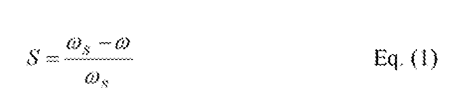
- exciter bridge DSP 206 controls exciter stator 120 such that the direction of the rotating field in the air gap in exciter 108 is opposite from the rotating direction of shaft 116, thus forcing exciter 108 to function as an induction machine in its braking mode.
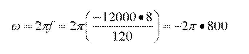
- fs is a frequency of an AC voltage supplied by exciter bridge 132 and is defined by Equation (2) as follows:
- RPM is a shaft speed and P is a number of poles of exciter 108.
- P is a number of poles of exciter 108.
- making the frequency of the AC exciter supply voltage generated by exciter bridge 132 substantially constant and reasonably small facilitates minimizing the power transferred from exciter stator 120 while still enabling exciter 108 to be appropriately controlled.
- RPM revolutions per minute
- Hz Hertz
- the power ratio between Ps and P n indicates that the majority of the power output from rotating rectifier 118 to exciter rotor winding 212 comes from the mechanical power transferred through shaft 116.
- the power from exciter stator 120 crossing the exciter air gap is also very small.
- the physical size of exciter bridge 132 may be minimized.
- system 100 receives electrical power from external power source 130.
- Main machine 106 operates as a 3-phase wound field salient synchronous motor in the start mode.
- 3-phase alternating current is supplied to 3-phase main stator winding 214 from main bridge 128, and an excitation current is provided to main rotor 114 from exciter 108.
- the frequency of the current supplied to main stator 112 is proportional to a speed of main machine 106.
- a rotating field generated by the 3-phase current interacts with a magnetic field generated by main rotor 114 to create mechanical torque at shaft 116 of main rotor 114.
- exciter stator 120 with 3-phase AC winding 210 and exciter rotor 122 with 3- phase AC winding 212 together form an induction exciter.
- Exciter bridge DSP 206 controls a direction of a phase sequence of the 3-phase AC windings 210 and 212 such that the direction is opposite from the rotational direction of shaft 116.
- the induction exciter operates in its braking mode. Consequently, the power transferred from exciter stator 120 may be minimized.
- the frequency of the supply voltage of exciter 108 is controlled in such a way that both the magnitude and the frequency of the supply voltage applied to exciter 108 are reduced along with the speed of shaft 116.
- FIG. 6 is a flowchart 400 illustrating an exemplary method of controlling a starting and generating system, such as starting and generating system 100 (shown in Figure 1), for use with an aircraft engine (not shown).
- a shaft speed of shaft 116 (shown in Figure 1) is determined 402 using ICC 104 (shown in Figure 1).
- control board 202 (shown in Figure 3) determines the shaft speed of shaft 116.
- ICC 104 determines 404 a desired first frequency for use in a start mode. Specifically, control board 202 determines the first frequency based on the shaft speed in order to avoid a high supply voltage demand during start mode.
- ICC 104 provides 406 S/G 102 (shown in Figure 1) with AC power at the first frequency.
- rectifier 118 shown in Figure 1 provides the AC power a the first frequency to exciter stator winding 210 (shown in Figure 3).
- Exciter 108 uses the AC power to provide excitation to main rotor 114 to start the aircraft engine.
- S/G 102 provides AC power at a second frequency for use in powering onboard electrical systems (not shown) within the aircraft during a generate mode.
- the second frequency is substantially constant and is less than the first, variable, frequency.
- ICC 104 controls 408 main machine 106 (shown in Figure 1) during the generate mode such that main machine 106 provides the onboard electrical systems with power.
- Embodiments of starting and generating systems for use with aircraft engines, and methods of control, are described in detail herein. Such systems facilitate providing fuel savings benefits via weight reduction and electrical power system optimization. Moreover, optimizing an excitation performance during both start and generate modes of such systems facilitates eliminating additional complexity, weight, size, and cost to produce and maintain such systems.
Landscapes
- Engineering & Computer Science (AREA)
- Chemical & Material Sciences (AREA)
- Combustion & Propulsion (AREA)
- Mechanical Engineering (AREA)
- General Engineering & Computer Science (AREA)
- Power Engineering (AREA)
- Control Of Eletrric Generators (AREA)
- Control Of Turbines (AREA)
Abstract
Description


Claims
Priority Applications (5)
| Application Number | Priority Date | Filing Date | Title |
|---|---|---|---|
| CN2010800225522A CN102428265B (en) | 2009-05-19 | 2010-03-31 | Aircraft Engine Starting/Generating System And Method Of Control |
| JP2012511832A JP5568129B2 (en) | 2009-05-19 | 2010-03-31 | Aircraft engine start / power generation system and control method |
| EP10722851.2A EP2432978B1 (en) | 2009-05-19 | 2010-03-31 | Aircraft engine starting/generating system and method of control |
| CA2760870A CA2760870C (en) | 2009-05-19 | 2010-03-31 | Aircraft engine starting/generating system and method of control |
| BRPI1009069A BRPI1009069B8 (en) | 2009-05-19 | 2010-03-31 | start-up system and control method of a start-up system |
Applications Claiming Priority (2)
| Application Number | Priority Date | Filing Date | Title |
|---|---|---|---|
| US12/468,206 US8148834B2 (en) | 2009-05-19 | 2009-05-19 | Aircraft engine starting/generating system and method of control |
| US12/468,206 | 2009-05-19 |
Publications (2)
| Publication Number | Publication Date |
|---|---|
| WO2010135030A2 true WO2010135030A2 (en) | 2010-11-25 |
| WO2010135030A3 WO2010135030A3 (en) | 2011-09-01 |
Family
ID=43124081
Family Applications (1)
| Application Number | Title | Priority Date | Filing Date |
|---|---|---|---|
| PCT/US2010/029299 WO2010135030A2 (en) | 2009-05-19 | 2010-03-31 | Aircraft engine starting/generating system and method of control |
Country Status (7)
| Country | Link |
|---|---|
| US (1) | US8148834B2 (en) |
| EP (1) | EP2432978B1 (en) |
| JP (1) | JP5568129B2 (en) |
| CN (1) | CN102428265B (en) |
| BR (1) | BRPI1009069B8 (en) |
| CA (1) | CA2760870C (en) |
| WO (1) | WO2010135030A2 (en) |
Cited By (2)
| Publication number | Priority date | Publication date | Assignee | Title |
|---|---|---|---|---|
| US8492920B2 (en) | 2011-10-07 | 2013-07-23 | Ge Aviation Systems Llc | Apparatus for generating power from a turbine engine |
| US8723385B2 (en) | 2011-10-07 | 2014-05-13 | General Electric Company | Generator |
Families Citing this family (34)
| Publication number | Priority date | Publication date | Assignee | Title |
|---|---|---|---|---|
| NZ556760A (en) * | 2007-07-26 | 2008-12-24 | Auckland Uniservices Ltd | An electric generator |
| US8362728B2 (en) * | 2010-09-15 | 2013-01-29 | Hamilton Sundstrand Corporation | Rotor position detection at standstill and low speeds using a PMG to operate a wound field synchronous machine |
| FR2968716B1 (en) * | 2010-12-13 | 2012-12-28 | Turbomeca | METHOD FOR CONTROLLING THE ELECTRIC GENERATION APPLIED TO AN AIRCRAFT GAS TURBINE AND TURBOMOTOR IMPLEMENTING SUCH A METHOD |
| FR2988694B1 (en) * | 2012-03-30 | 2014-03-28 | Hispano Suiza Sa | DEVICE FOR ELECTRICALLY SUPPLYING AN AIRCRAFT ON THE GROUND |
| FR2990004B1 (en) * | 2012-04-27 | 2014-04-18 | Turbomeca | METHOD AND SYSTEM FOR EMERGENCY STARTING ENERGY GENERATING ARCHITECTURE |
| GB2504754B (en) * | 2012-08-09 | 2018-07-04 | Safran Power Uk Ltd | Aircraft engine electrical apparatus |
| CN102780443B (en) * | 2012-08-14 | 2014-07-16 | 西北工业大学 | Aerial three-level electric excitation motor starting control method and aerial three-level electric excitation motor starting control device |
| US9657645B2 (en) | 2013-02-25 | 2017-05-23 | Pratt & Whitney Canada Corp. | Engine architecture using electric machine |
| WO2014196981A1 (en) * | 2013-06-07 | 2014-12-11 | Ge Aviation Systems Llc | Turbofan engine with generator |
| US9035478B2 (en) | 2013-08-26 | 2015-05-19 | Ge Aviation Systems, Llc | Aircraft engine constant frequency starter/generator |
| EP3042442A1 (en) * | 2013-09-06 | 2016-07-13 | GE Aviation Systems LLC | Rotor assembly for an electric machine |
| CN105765214B (en) * | 2013-09-06 | 2017-11-07 | 通用电气航空系统有限责任公司 | For the method for the engine for starting airborne vehicle |
| US9041232B2 (en) | 2013-10-11 | 2015-05-26 | General Electric Company | Electric generator system |
| US9252695B2 (en) * | 2014-03-12 | 2016-02-02 | General Electric Company | Brushless permanent magnet generator plus auxiliary voltage source constant potential exciter |
| US9246425B2 (en) * | 2014-04-29 | 2016-01-26 | Gulfstream Aerospace Corporation | Apparatus and systems for engine and generator control within an aircraft |
| JP2018509124A (en) | 2015-02-18 | 2018-03-29 | ジーイー・アビエイション・システムズ・エルエルシー | Aircraft start-up and power generation system |
| WO2016133503A1 (en) | 2015-02-18 | 2016-08-25 | Ge Aviation Systems Llc | Aircraft starting and generating system |
| JP2018506952A (en) * | 2015-02-18 | 2018-03-08 | ジーイー・アビエイション・システムズ・エルエルシー | Aircraft start-up and power generation system |
| US10273876B2 (en) | 2015-06-08 | 2019-04-30 | Kohler Co. | Dual axis alternator |
| US20160365814A1 (en) * | 2015-06-09 | 2016-12-15 | Hamilton Sundstrand Corporation | Variable speed ac generator system including independently controlled rotor field |
| US20170107910A1 (en) * | 2015-10-15 | 2017-04-20 | Ge Aviation Systems Llc | Method and apparatus for starting an aircraft engine and operating a power architecture for an aircraft |
| GB2545653A (en) * | 2015-12-18 | 2017-06-28 | Labinal Power Systems | Multi-stage synchronous generator |
| US11028812B2 (en) | 2016-07-27 | 2021-06-08 | Astronics Advanced Electronic Systems Corp. | Integrated brushless starter generator |
| US11043880B2 (en) * | 2016-11-10 | 2021-06-22 | Hamilton Sunstrand Corporation | Electric power generating system with a synchronous generator |
| US11476729B2 (en) * | 2017-03-03 | 2022-10-18 | Ge Renewable Technologies | Salient pole machine with rotor having rotor rim with pole-rim interface and fixation points |
| DE102017108012A1 (en) * | 2017-04-13 | 2018-10-18 | Primetals Technologies Germany Gmbh | Implementation of control in multicore processor |
| US10326394B2 (en) | 2017-10-24 | 2019-06-18 | Hamilton Sundstrand Corporation | Wound field generator overvoltage prevention |
| US10415530B2 (en) * | 2018-01-16 | 2019-09-17 | The Boeing Company | System and method for operating an independent speed variable frequency generator as a starter |
| DE102018118275A1 (en) * | 2018-07-27 | 2020-01-30 | Valeo Siemens Eautomotive Germany Gmbh | Rotor assembly for an electric machine, electric machine for a vehicle and vehicle |
| US10547259B1 (en) * | 2018-08-03 | 2020-01-28 | Hamilton Sundstrand Corporation | Electric generating system with an interleaved DC-DC converter |
| US10723469B2 (en) | 2018-09-21 | 2020-07-28 | Hamilton Sunstrand Corporation | System and method for driving electrically driving a gas turbine engine via a wound field synchronous machine assisted by a PMG |
| CN109484640A (en) * | 2018-12-28 | 2019-03-19 | 河南三和航空工业有限公司 | It is a kind of starting, power generation integrated vertical take-off and landing drone |
| DE102019202475A1 (en) * | 2019-02-25 | 2020-08-27 | Robert Bosch Gmbh | Method and arrangement for supporting a starting process of an internal combustion engine |
| CN111009992B (en) * | 2019-12-05 | 2021-05-28 | 北京动力机械研究所 | High-low voltage compatible built-in brushless direct current starting power generation system |
Family Cites Families (26)
| Publication number | Priority date | Publication date | Assignee | Title |
|---|---|---|---|---|
| US4481459A (en) * | 1983-12-20 | 1984-11-06 | Sundstrand Corporation | Combined starting/generating system and method |
| US4743777A (en) * | 1986-03-07 | 1988-05-10 | Westinghouse Electric Corp. | Starter generator system with two stator exciter windings |
| US4939411A (en) * | 1986-11-19 | 1990-07-03 | North American Philips Corporation | Composite vacuum evaporation coil |
| DE3827529A1 (en) * | 1988-08-13 | 1990-02-22 | Bayer Ag | THERMOPLASTIC MOLDS FROM POLYAMIDE AND HYDRATED NITRILE RUBBER |
| US4967096A (en) * | 1989-01-26 | 1990-10-30 | Sundstrand Corporation | Cross-start bus configuration for a variable speed constant frequency electric power system |
| US5023537A (en) * | 1989-08-23 | 1991-06-11 | Sundstrand Corporation | Low frequency feeder fault protection |
| US5055700A (en) * | 1989-10-16 | 1991-10-08 | Dhyanchand P John | Brushless generator having prime mover start capability |
| US5015941A (en) * | 1989-10-30 | 1991-05-14 | Sundstrand Corporation | Power conversion system with bi-directional power converter having prime mover start capability |
| US5013929A (en) * | 1989-11-22 | 1991-05-07 | Sundstrand Corporation | Power conversion system having prime mover start capability |
| US5097195A (en) * | 1989-11-27 | 1992-03-17 | Sundstrand Corporation | AC exciter for VSCF starter/generator |
| US5068590A (en) * | 1989-12-20 | 1991-11-26 | Sundstrand Corporation | Brushless generator having AC excitation in generating and starting modes |
| US5309081A (en) * | 1992-08-18 | 1994-05-03 | Sundstrand Corporation | Power conversion system with dual permanent magnet generator having prime mover start capability |
| FR2769952A1 (en) * | 1997-10-20 | 1999-04-23 | Aerospatiale | STARTING DEVICE FOR A GAS TURBINE IN AN AIRCRAFT |
| US6188204B1 (en) * | 1999-08-05 | 2001-02-13 | Joseph Vithayathil | Brushless AC field system for stable frequency variable speed alternators |
| EP1289118A1 (en) | 2001-08-24 | 2003-03-05 | Siemens Aktiengesellschaft | Method and arrangement for starting a turbo set |
| US6838779B1 (en) * | 2002-06-24 | 2005-01-04 | Hamilton Sundstrand Corporation | Aircraft starter generator for variable frequency (vf) electrical system |
| US6998726B2 (en) * | 2002-12-10 | 2006-02-14 | Honeywell International Inc. | Method and system for providing single-phase excitation techniques to a start exciter in a starter/generator system |
| JP2004282826A (en) * | 2003-03-13 | 2004-10-07 | Honda Motor Co Ltd | Engine driven generator |
| US20040183308A1 (en) * | 2003-03-17 | 2004-09-23 | Mingzhou Xu | Gas turbine engine starter generator that selectively changes the number of rotor poles |
| US7250688B2 (en) * | 2004-07-14 | 2007-07-31 | Hamilton Sundstrand Corporation | Narrow range variable frequency starter/generator system |
| US7078826B2 (en) * | 2004-08-17 | 2006-07-18 | Honeywell International, Inc. | Hybrid gas turbine engine starter-generator |
| US20060087293A1 (en) * | 2004-10-26 | 2006-04-27 | Honeywell International, Inc. | AC generator with independently controlled field rotational speed |
| US7301311B2 (en) | 2006-02-22 | 2007-11-27 | Honeywell International, Inc. | Brushless starter-generator with independently controllable exciter field |
| US7508086B2 (en) | 2006-03-24 | 2009-03-24 | General Electric Company | Aircraft engine starter/generator and controller |
| US7687928B2 (en) * | 2006-06-14 | 2010-03-30 | Smiths Aerospace, Llc | Dual-structured aircraft engine starter/generator |
| US7388300B2 (en) * | 2006-09-20 | 2008-06-17 | Honeywell International, Inc. | Starter-generator operable with multiple variable frequencies and voltages |
-
2009
- 2009-05-19 US US12/468,206 patent/US8148834B2/en active Active
-
2010
- 2010-03-31 CA CA2760870A patent/CA2760870C/en not_active Expired - Fee Related
- 2010-03-31 CN CN2010800225522A patent/CN102428265B/en active Active
- 2010-03-31 BR BRPI1009069A patent/BRPI1009069B8/en not_active IP Right Cessation
- 2010-03-31 EP EP10722851.2A patent/EP2432978B1/en active Active
- 2010-03-31 WO PCT/US2010/029299 patent/WO2010135030A2/en active Application Filing
- 2010-03-31 JP JP2012511832A patent/JP5568129B2/en not_active Expired - Fee Related
Non-Patent Citations (1)
| Title |
|---|
| None |
Cited By (3)
| Publication number | Priority date | Publication date | Assignee | Title |
|---|---|---|---|---|
| US8492920B2 (en) | 2011-10-07 | 2013-07-23 | Ge Aviation Systems Llc | Apparatus for generating power from a turbine engine |
| US8723349B2 (en) | 2011-10-07 | 2014-05-13 | General Electric Company | Apparatus for generating power from a turbine engine |
| US8723385B2 (en) | 2011-10-07 | 2014-05-13 | General Electric Company | Generator |
Also Published As
| Publication number | Publication date |
|---|---|
| US8148834B2 (en) | 2012-04-03 |
| CN102428265A (en) | 2012-04-25 |
| EP2432978A2 (en) | 2012-03-28 |
| CA2760870A1 (en) | 2010-11-25 |
| WO2010135030A3 (en) | 2011-09-01 |
| BRPI1009069B8 (en) | 2019-08-20 |
| JP5568129B2 (en) | 2014-08-06 |
| BRPI1009069B1 (en) | 2019-07-30 |
| JP2012527863A (en) | 2012-11-08 |
| EP2432978B1 (en) | 2016-10-12 |
| CN102428265B (en) | 2013-06-19 |
| BRPI1009069A2 (en) | 2016-03-01 |
| US20100295301A1 (en) | 2010-11-25 |
| CA2760870C (en) | 2015-09-08 |
Similar Documents
| Publication | Publication Date | Title |
|---|---|---|
| US8148834B2 (en) | Aircraft engine starting/generating system and method of control | |
| JP5681678B2 (en) | Aircraft engine starter / generator and controller | |
| US7514806B2 (en) | Engine start system with quadrature AC excitation | |
| US7301311B2 (en) | Brushless starter-generator with independently controllable exciter field | |
| US7116073B1 (en) | Methods and apparatus for controlling a motor/generator | |
| JPH10509017A (en) | Starter generator system and method using a low voltage source | |
| WO2006047524A1 (en) | Ac generator with independently controlled field rotational speed | |
| US20140265693A1 (en) | Integrated starter generator | |
| US20140008972A1 (en) | Electrical power supply for an aircraft | |
| US7990115B2 (en) | High frequency generator without rotating diode rectifier | |
| US7135829B1 (en) | Methods and apparatus for controlling a motor/generator | |
| EP1232562B1 (en) | Induction static start for a turbine generator with a brushless exciter and associated methods | |
| US20080023966A1 (en) | System and method for propelling a large land-based vehicle using a dual function brushless dynamoelectric machine | |
| JP2013236480A (en) | Induction brushless ac excitation system | |
| EP1753123B1 (en) | Methods and apparatus for controlling a motor/generator | |
| Brooking et al. | An integrated engine-generator set with power electronic interface for hybrid electric vehicle applications | |
| TWI793311B (en) | Externally modulated independent speed variable frequency generator | |
| Chakraborty et al. | A new series of brushless and permanent magnetless synchronous machines | |
| CN107834784B (en) | Design method for starting/generator Stators for Switched Reluctance Motors umber of turn | |
| JPH0538054A (en) | Phase modifier | |
| CN200997551Y (en) | Triple-phase brushless generater of speed-adjusting constant-frequency and voltage with power-driven during advance | |
| JP2003102153A (en) | Alternating current generator-motor for vehicle | |
| JP2006101633A (en) | Engine generation device |
Legal Events
| Date | Code | Title | Description |
|---|---|---|---|
| WWE | Wipo information: entry into national phase |
Ref document number: 201080022552.2 Country of ref document: CN |
|
| 121 | Ep: the epo has been informed by wipo that ep was designated in this application |
Ref document number: 10722851 Country of ref document: EP Kind code of ref document: A2 |
|
| WWE | Wipo information: entry into national phase |
Ref document number: 2760870 Country of ref document: CA |
|
| REEP | Request for entry into the european phase |
Ref document number: 2010722851 Country of ref document: EP |
|
| WWE | Wipo information: entry into national phase |
Ref document number: 2010722851 Country of ref document: EP |
|
| WWE | Wipo information: entry into national phase |
Ref document number: 2012511832 Country of ref document: JP |
|
| WWE | Wipo information: entry into national phase |
Ref document number: 9057/DELNP/2011 Country of ref document: IN |
|
| NENP | Non-entry into the national phase |
Ref country code: DE |
|
| 121 | Ep: the epo has been informed by wipo that ep was designated in this application |
Ref document number: 10722851 Country of ref document: EP Kind code of ref document: A2 |
|
| REG | Reference to national code |
Ref country code: BR Ref legal event code: B01A Ref document number: PI1009069 Country of ref document: BR |
|
| ENP | Entry into the national phase |
Ref document number: PI1009069 Country of ref document: BR Kind code of ref document: A2 Effective date: 20111110 |