WO2010114252A2 - Method for transmitting control information in wireless communication system and apparatus therefor - Google Patents

Method for transmitting control information in wireless communication system and apparatus therefor Download PDF

Info

Publication number
WO2010114252A2
WO2010114252A2 PCT/KR2010/001810 KR2010001810W WO2010114252A2 WO 2010114252 A2 WO2010114252 A2 WO 2010114252A2 KR 2010001810 W KR2010001810 W KR 2010001810W WO 2010114252 A2 WO2010114252 A2 WO 2010114252A2
Authority
WO
WIPO (PCT)
Prior art keywords
ack
nack
data blocks
transmitting
downlink component
Prior art date
Application number
PCT/KR2010/001810
Other languages
French (fr)
Other versions
WO2010114252A3 (en
Inventor
Yeong Hyeon Kwon
Jae Hoon Chung
Seung Hee Han
So Yeon Kim
Original Assignee
Lg Electronics Inc.
Priority date (The priority date is an assumption and is not a legal conclusion. Google has not performed a legal analysis and makes no representation as to the accuracy of the date listed.)
Filing date
Publication date
Priority to CN201080014088.2A priority Critical patent/CN102365837B/en
Priority to US13/254,323 priority patent/US9401779B2/en
Priority to KR1020117018686A priority patent/KR101186619B1/en
Application filed by Lg Electronics Inc. filed Critical Lg Electronics Inc.
Publication of WO2010114252A2 publication Critical patent/WO2010114252A2/en
Publication of WO2010114252A3 publication Critical patent/WO2010114252A3/en
Priority to US14/553,771 priority patent/US9401780B2/en
Priority to US14/553,837 priority patent/US9525518B2/en
Priority to US15/357,485 priority patent/US9742545B2/en
Priority to US15/658,979 priority patent/US10063360B2/en
Priority to US16/049,270 priority patent/US10211963B2/en
Priority to US16/239,168 priority patent/US10505693B2/en
Priority to US16/708,225 priority patent/US10911206B2/en
Priority to US16/877,718 priority patent/US10855431B2/en
Priority to US17/156,098 priority patent/US11546118B2/en

Links

Classifications

    • HELECTRICITY
    • H04ELECTRIC COMMUNICATION TECHNIQUE
    • H04LTRANSMISSION OF DIGITAL INFORMATION, e.g. TELEGRAPHIC COMMUNICATION
    • H04L5/00Arrangements affording multiple use of the transmission path
    • H04L5/003Arrangements for allocating sub-channels of the transmission path
    • H04L5/0053Allocation of signaling, i.e. of overhead other than pilot signals
    • H04L5/0055Physical resource allocation for ACK/NACK
    • HELECTRICITY
    • H04ELECTRIC COMMUNICATION TECHNIQUE
    • H04LTRANSMISSION OF DIGITAL INFORMATION, e.g. TELEGRAPHIC COMMUNICATION
    • H04L1/00Arrangements for detecting or preventing errors in the information received
    • H04L1/12Arrangements for detecting or preventing errors in the information received by using return channel
    • H04L1/16Arrangements for detecting or preventing errors in the information received by using return channel in which the return channel carries supervisory signals, e.g. repetition request signals
    • H04L1/1607Details of the supervisory signal
    • H04L1/1614Details of the supervisory signal using bitmaps
    • HELECTRICITY
    • H04ELECTRIC COMMUNICATION TECHNIQUE
    • H04LTRANSMISSION OF DIGITAL INFORMATION, e.g. TELEGRAPHIC COMMUNICATION
    • H04L1/00Arrangements for detecting or preventing errors in the information received
    • H04L1/12Arrangements for detecting or preventing errors in the information received by using return channel
    • H04L1/16Arrangements for detecting or preventing errors in the information received by using return channel in which the return channel carries supervisory signals, e.g. repetition request signals
    • H04L1/18Automatic repetition systems, e.g. Van Duuren systems
    • H04L1/1829Arrangements specially adapted for the receiver end
    • H04L1/1854Scheduling and prioritising arrangements
    • HELECTRICITY
    • H04ELECTRIC COMMUNICATION TECHNIQUE
    • H04LTRANSMISSION OF DIGITAL INFORMATION, e.g. TELEGRAPHIC COMMUNICATION
    • H04L1/00Arrangements for detecting or preventing errors in the information received
    • H04L1/12Arrangements for detecting or preventing errors in the information received by using return channel
    • H04L1/16Arrangements for detecting or preventing errors in the information received by using return channel in which the return channel carries supervisory signals, e.g. repetition request signals
    • H04L1/18Automatic repetition systems, e.g. Van Duuren systems
    • H04L1/1829Arrangements specially adapted for the receiver end
    • H04L1/1858Transmission or retransmission of more than one copy of acknowledgement message
    • HELECTRICITY
    • H04ELECTRIC COMMUNICATION TECHNIQUE
    • H04LTRANSMISSION OF DIGITAL INFORMATION, e.g. TELEGRAPHIC COMMUNICATION
    • H04L1/00Arrangements for detecting or preventing errors in the information received
    • H04L1/12Arrangements for detecting or preventing errors in the information received by using return channel
    • H04L1/16Arrangements for detecting or preventing errors in the information received by using return channel in which the return channel carries supervisory signals, e.g. repetition request signals
    • H04L1/18Automatic repetition systems, e.g. Van Duuren systems
    • H04L1/1829Arrangements specially adapted for the receiver end
    • H04L1/1861Physical mapping arrangements
    • HELECTRICITY
    • H04ELECTRIC COMMUNICATION TECHNIQUE
    • H04LTRANSMISSION OF DIGITAL INFORMATION, e.g. TELEGRAPHIC COMMUNICATION
    • H04L5/00Arrangements affording multiple use of the transmission path
    • H04L5/0001Arrangements for dividing the transmission path
    • H04L5/0003Two-dimensional division
    • H04L5/0005Time-frequency
    • H04L5/0007Time-frequency the frequencies being orthogonal, e.g. OFDM(A), DMT
    • HELECTRICITY
    • H04ELECTRIC COMMUNICATION TECHNIQUE
    • H04LTRANSMISSION OF DIGITAL INFORMATION, e.g. TELEGRAPHIC COMMUNICATION
    • H04L5/00Arrangements affording multiple use of the transmission path
    • H04L5/003Arrangements for allocating sub-channels of the transmission path
    • H04L5/0053Allocation of signaling, i.e. of overhead other than pilot signals
    • HELECTRICITY
    • H04ELECTRIC COMMUNICATION TECHNIQUE
    • H04WWIRELESS COMMUNICATION NETWORKS
    • H04W72/00Local resource management
    • H04W72/20Control channels or signalling for resource management
    • H04W72/23Control channels or signalling for resource management in the downlink direction of a wireless link, i.e. towards a terminal
    • HELECTRICITY
    • H04ELECTRIC COMMUNICATION TECHNIQUE
    • H04LTRANSMISSION OF DIGITAL INFORMATION, e.g. TELEGRAPHIC COMMUNICATION
    • H04L1/00Arrangements for detecting or preventing errors in the information received
    • H04L1/0001Systems modifying transmission characteristics according to link quality, e.g. power backoff
    • H04L1/0002Systems modifying transmission characteristics according to link quality, e.g. power backoff by adapting the transmission rate
    • H04L1/0003Systems modifying transmission characteristics according to link quality, e.g. power backoff by adapting the transmission rate by switching between different modulation schemes
    • HELECTRICITY
    • H04ELECTRIC COMMUNICATION TECHNIQUE
    • H04LTRANSMISSION OF DIGITAL INFORMATION, e.g. TELEGRAPHIC COMMUNICATION
    • H04L1/00Arrangements for detecting or preventing errors in the information received
    • H04L1/12Arrangements for detecting or preventing errors in the information received by using return channel
    • H04L1/16Arrangements for detecting or preventing errors in the information received by using return channel in which the return channel carries supervisory signals, e.g. repetition request signals
    • H04L1/1607Details of the supervisory signal
    • H04L1/1692Physical properties of the supervisory signal, e.g. acknowledgement by energy bursts
    • HELECTRICITY
    • H04ELECTRIC COMMUNICATION TECHNIQUE
    • H04WWIRELESS COMMUNICATION NETWORKS
    • H04W72/00Local resource management
    • H04W72/20Control channels or signalling for resource management

Definitions

  • the present invention relates to a method for transmitting a control signal in a wireless communication system, and more particularly, to a method for transmitting ACK/NACK signal from a user equipment in a wireless communication system to which carrier aggregation is applied.
  • a 3 rd generation partnership project long term evolution (3GPP LTE) communication system which is an example of a mobile communication system to which the present invention can be applied will be described in brief.
  • FIG. 1 is a diagram illustrating a network structure of an Evolved Universal Mobile Telecommunications System
  • E-UMTS which is an example of a mobile communication system.
  • the E-UMTS is an evolved version of the conventional UMTS system, and its basic standardization is in progress under the 3rd Generation Partnership Project
  • the E-UMTS may also be referred to as a Long Term
  • LTE Long Term Evolution
  • the E-UMTS includes a User
  • UE 120 User Equipment (UE) 120
  • base stations eNode B and eNB 110a and 110b
  • an Access Gateway which is located at an end of a network (E-UTRAN) and connected to an external network.
  • the base stations can simultaneously transmit multiple data streams for a broadcast service, a multicast service and/or a unicast service.
  • One or more cells may exist for one base station.
  • One cell is set to one of bandwidths of 1.25, 2.5, 5, 10, and 20Mhz to provide a downlink or uplink transport service to several user equipments. Different cells may be set to provide different bandwidths.
  • one base station controls data transmission and reception for a plurality of user equipments. The base station transmits downlink (DL) scheduling information of downlink data to the corresponding user equipment to notify the user equipment of time and frequency domains to which data will be transmitted and information related to encoding, data size, hybrid automatic repeat and request (HARQ) .
  • DL downlink
  • HARQ hybrid automatic repeat and request
  • the base station transmits uplink (UL) scheduling information of uplink data to the corresponding user equipment to notify the user equipment of time and frequency domains that can be used by the corresponding user equipment, and information related to encoding, data size, HARQ.
  • UL uplink
  • An interface for transmitting user traffic or control traffic can be used between the base stations.
  • a Core Network (CN) may include the AG and a network node or the like for user registration of the UE.
  • the AG manages mobility of a UE on a Tracking Area (TA) basis, wherein one TA includes a plurality of cells.
  • TA Tracking Area
  • LTE-Advanced LTE-Advanced
  • the LTE-A system aims to support a wideband of maximum 100MHz.
  • the LTE-A system uses carrier aggregation or bandwidth aggregation that achieves a wideband using a plurality of component carriers.
  • Carrier aggregation allows a plurality of component carriers to be used as one logical frequency band, whereby a wider frequency band is used.
  • a bandwidth of each component carrier can be defined based on a bandwidth of a system block used in the LTE system.
  • the present invention is directed to a method for transmitting a control signal in a wireless communication system and an apparatus therefor, which substantially obviate one or more problems due to limitations and disadvantages of the related art.
  • An object of the present invention is to provide a method and apparatus for transmitting ACK/NACK signal in a wireless communication system to which carrier aggregation is applied. Additional advantages, objects, and features of the invention will be set forth in part in the description which follows and in part will become apparent to those having ordinary skill in the art upon examination of the following or may be learned from practice of the invention. The objectives and other advantages of the invention may be realized and attained by the structure particularly pointed out in the written description and claims hereof as well as the appended drawings . [Technical Solution]
  • a method for transmitting ACK/NACK (Acknowledgement/Negative ACK) signals in a wireless communication system comprises receiving a plurality of data blocks from a base station; generating ACK/NACK signals corresponding to the plurality of data blocks; allocating resources for transmitting the ACK/NACK signals, wherein the resources are allocated independently per slot; and transmitting the ACK/NACK signals through one uplink component carrier by using the allocated resources.
  • the plurality of data blocks are received at the same time through a plurality of downlink component carriers.
  • step of receiving a plurality of data blocks includes receiving two or more data blocks through at least one downlink component carrier among the plurality of downlink component carriers.
  • a method for transmitting ACK/NACK (Acknowledgement/Negative ACK) signals in a wireless communication system comprises receiving a plurality of data blocks through a plurality of downlink component carriers from a base station; generating ACK/NACK signals corresponding to the plurality of data blocks; mapping the ACK/NACK signals into a bit index; allocating control channel resources for transmitting the bit index; and transmitting the bit index through one uplink component carrier by using the allocated control channel resources.
  • the control channel resources are payload of PUCCH (physical uplink control channel) format 2.
  • a method for transmitting ACK/NACK (Acknowledgement/Negative ACK) signals in a wireless communication system comprises receiving a plurality of data blocks through a plurality of downlink component carriers from a base station; generating ACK/NACK signals corresponding to the plurality of data blocks; allocating containers for transmitting the ACK/NACK signals in control channel resources in accordance with an index order of the downlink component carriers as much as the received data blocks; and transmitting the ACK/NACK signals through one uplink component carrier by using the allocated containers.
  • the control channel resources are preferably payload of PUCCH (physical uplink control channel) format 2.
  • the step of receiving a plurality of data blocks includes receiving two or more data blocks through at least one downlink component carrier among the plurality of downlink component carriers, and the step of allocating containers includes allocating the containers in accordance with the order of the data blocks received through the at least one downlink component carrier.
  • a user equipment comprises a receiving module receiving a plurality of data blocks from a base station; a processor generating ACK/NACK signals corresponding to the plurality of data blocks and allocating resources for transmitting the ACK/NACK signals, wherein the resources are allocated independently per slot; and a transmitting module transmitting the ACK/NACK signals through one uplink component carrier by using the allocated resources.
  • the receiving module receives the plurality of data blocks at the same time through a plurality of downlink component carriers.
  • the receiving module receives two or more data blocks through at least one downlink component carrier among the plurality of downlink component carriers .
  • the processor allocates the resources to minimize the difference in the number of the ACK/NACK signals transmitted per slot.
  • a user equipment comprises a receiving module receiving a plurality of data blocks at the same time through a plurality of downlink component carriers from a base station; a processor generating ACK/NACK signals corresponding to the plurality of data blocks, mapping the ACK/NACK signals into a bit index, and allocating control channel resources for transmitting the bit index; and a transmitting module transmitting the bit index through one uplink component carrier by using the allocated control channel resources.
  • the control channel resources are preferably payload of PUCCH (physical uplink control channel) format 2.
  • a user equipment comprises a receiving module receiving a plurality of data blocks at the same time through a plurality of downlink component carriers from a base station; a processor generating ACK/NACK ⁇ 'signals corresponding to the plurality of data blocks and allocating containers for transmitting the ACK/NACK signals in control channel resources in accordance with an index order of the downlink component carriers as much as the received data blocks; and a transmitting module transmitting the ACK/NACK signals through one uplink component carrier by using the allocated containers.
  • control channel resources are preferably payload of PUCCH (physical uplink control channel) format 2.
  • the receiving module receives a plurality of data blocks includes receiving two or more data blocks through at least one downlink component carrier among the plurality of downlink component carriers, and the processor allocates the containers in accordance with the order of the data blocks received through the at least one downlink component carrier.
  • ACK/NACK signals can be transmitted efficiently in the wireless communication system to which carrier aggregation is applied. It is to be understood that the advantages that can be obtained by the present invention are not limited to the aforementioned advantages and other advantages which are not mentioned will be apparent from the following description to the person with an ordinary skill in the art to which the present invention pertains. [Description of Drawings] The accompanying drawings, which are included to provide a further understanding of the invention and are incorporated in and constitute a part of this application, illustrate embodiment (s) of the invention and together with the description serve to explain the principle of the invention. In the drawings:
  • FIG. 1 is a diagram illustrating a network structure of an Evolved Universal Mobile Telecommunications System (E-UMTS) which is an example of a mobile communication system;
  • E-UMTS Evolved Universal Mobile Telecommunications System
  • FIG. 2 is a diagram illustrating a transmitter and a receiver for OFDMA and SC-FDMA
  • FIG. 3 is a diagram illustrating a structure of a radio frame used in an LTE system
  • FIG. 4 is a diagram illustrating a structure of a downlink radio frame used in an LTE system
  • FIG. 5 is a diagram illustrating a structure of an uplink subframe used in an LTE system
  • FIG. 6 is a diagram illustrating a structure of a PUCCH for ACK/NACK transmission in an LTE system
  • FIG. 7 is a diagram illustrating an example of determining PUCCH resources for ACK/NACK signal transmission
  • FIG. 8 is a diagram illustrating an example of communication performed under multiple component carriers
  • FIG. 9 is a diagram illustrating a PUCCH Format 1 extension scheme according to one embodiment of the present invention.
  • FIG. 10 is a diagram illustrating a PUCCH Format 2 extension scheme according to one embodiment of the present invention.
  • FIG. 11 is a diagram illustrating a PUCCH Format 2 extension scheme according to another embodiment of the present invention.
  • FIG. 12 is a diagram illustrating a method for allocating a plurality of ACK/NACK information to payload of PUCCH format 2 in accordance with one embodiment of the present invention
  • FIG. 13 is a diagram illustrating a method for allocating a plurality of ACK/NACK/DTX information to payload of PUCCH format 2 in accordance with one embodiment of the present invention
  • FIG. 14 is a diagram illustrating a method for transmitting ACK/NACK/DTX information in accordance with one embodiment of the present invention when a base station is operated in a MIMO mode and the number of downlink component carriers is less than 4;
  • FIG. 15 is a diagram illustrating a method for transmitting ACK/NACK/DTX information in accordance with one embodiment of the present invention when a base station is operated in a MIMO mode and the number of downlink component carriers is more than 5;
  • FIG. 16 is a diagram illustrating a case where component carriers 1 and 3 are operated in a Non-MIMO mode and the other component carriers are operated in a MIMO mode ;
  • FIG. 17 is a diagram illustrating a method for allocating PUCCH format 2 dedicated resources according to one embodiment of the present invention.
  • FIG. 18 is a diagram illustrating an example of using PUCCH format 2 dedicated resources allocated as resources for LTE-A in accordance with one embodiment of the present invention.
  • FIG. 19 is a diagram illustrating another method for transmitting ACK/NACK information in accordance with one embodiment of the present invention.
  • FIG. 20 is a diagram illustrating an example of transmitting ACK/NACK information according to one embodiment of the present invention in case of normal CP;
  • FIG. 21 is a diagram illustrating an example of transmitting ACK/NACK information according to one embodiment of the present invention in case of extended CP;
  • FIG. 22 is a diagram illustrating a case where ACK/NACK information of a specific downlink component carrier is repeated.
  • FIG. 23 is a diagram illustrating a base station and a user equipment that can be applied to the embodiment of the present invention. [Mode for Invention]
  • a system that includes a system band of a single component carrier will be referred to as a legacy system or a narrowband system.
  • a system that includes a system band of a plurality of component carriers and uses at least one or more component carriers as a system block of a legacy system will be referred to as an evolved system or a wideband system.
  • the component carrier used as a legacy system block has the same size as that of the system block of the legacy system.
  • the sizes of the other component carriers may be determined based on the size of the system block of the legacy system.
  • the 3GPP LTE (Release-8) system and the 3GPP LTE-A (Release- 9) system are evolved from the legacy system.
  • the 3GPP LTE (Release-8) system will herein be referred to as an LTE system or the legacy system.
  • a user equipment that supports the LTE system will be referred to as an LTE user equipment or a legacy user equipment.
  • the 3GPP LTE-A (Release-9) system will be referred to as an LTE-A system or an evolved system.
  • a user equipment that supports the LTE-A system will be referred to as an LTE-A user equipment or an evolved user equipment .
  • FIG. 2 is a block diagram illustrating a transmitter and a receiver for OFDMA and SC-FDMA.
  • a transmitter 202-214 may be a part of a user equipment
  • a receiver 216-230 may be a part of a base station.
  • a transmitter may be a part of a base station
  • a receiver may be a part of a user equipment.
  • an OFDMA transmitter includes a serial to parallel converter 202, a sub-carrier mapping module 206, an M-point inverse discrete fourier transform (IDFT) module 208, a cyclic prefix (CP) addition module 210, a parallel to serial converter 212, and a radio frequency (RF) /digital to analog converter (DAC) module 214.
  • IDFT M-point inverse discrete fourier transform
  • CP cyclic prefix
  • RF radio frequency
  • DAC digital to analog converter
  • bit streams are modulated to data symbol sequences .
  • the bit streams can be obtained by performing various signal processes, such as channel encoding, interleaving and scrambling, for a data block transferred from a medium access control (MAC) layer.
  • the bit streams may be designated as codewords, and are equivalent to the data block transferred from the MAC layer.
  • the data block transferred from the MAC layer may be designated as a transmission block.
  • Examples of a modulation scheme include, but not limited to, BPSK (binary phase shift keying) , QPSK
  • n-QAM quadrature amplitude modulation
  • the data symbol sequences in series are converted to parallel data symbol sequences as much as N (202) .
  • N number of data symbols are mapped with N number of subcarrers allocated among a total of M number of subcarriers, and the other M-N number of carriers are padded with 0 (206) .
  • the data symbols mapped in a frequency domain are converted to time domain sequences through M-point IDFT processing (208).
  • cyclic prefix is added to the time domain sequences to generate OFDMA symbols (210) .
  • the generated OFDMA symbols are converted from parallel symbols to serial symbols (212) . Then, the OFDMA symbols are transmitted to the receiver through digital-to-analog conversion and frequency uplink conversion (214) . Other user is allocated with available subcarriers among the remaining M-N number of subcarriers.
  • the OFDMA receiver includes an RF/ADC (analog to digital converter) module 216, a serial-to-parallel converter 218, a cyclic prefix (CP) removing module 220, an M-point discrete fourier transform (DFT) module 224, a subcarrier demapping/equalization module 226, a parallel-to-digital converter 228, and a detection module 230.
  • RF/ADC analog to digital converter
  • CP cyclic prefix
  • DFT discrete fourier transform
  • a signal processing procedure of the OFDMA receiver will be configured in reverse order of the OFDMA transmitter.
  • the SC-FDMA transmitter additionally includes an N-point DFT module 204 prior to the subcarrier mapping module 206.
  • the SC-FDMA transmitter can reduce a peak-to-average power ratio (PAPR) of a transmitting signal more remarkably than the OFDMA transmitter by spreading a plurality of data to the frequency domain through DFT prior IDFT processing.
  • the SC-FDMA receiver additionally includes an N-point IDFT module 228 after the subcarrier demapping module 226.
  • a signal processing procedure of the SC-FDMA receiver will be configured in reverse order of the SC-FDMA transmitter.
  • FIG. 3 is a diagram illustrating a structure of a radio frame used in the LTE system.
  • the radio frame has a length of 10ms (327200 -T 3 ) and includes 10 subframes of an equal size.
  • Each sub frame has a length of lms and includes two slots.
  • Each slot has a length of 0.5ms (15360 -T 3 ) .
  • the slot includes a plurality of OFDMA (or SC-FDMA) symbols in a time domain, and includes a plurality of resource blocks (RBs) in a frequency domain.
  • OFDMA or SC-FDMA
  • one resource block includes twelve (12) subcarriers X seven (or six) OFDMA (or SC-FDMA) symbols.
  • a transmission time interval (TTI) which is a transmission unit time of data can be determined in a unit of one or more subframes.
  • the aforementioned structure of the radio frame is only exemplary, and various modifications can be made in the number of subframes included in the radio frame or the number of slots included in the subframe, or the number of OFDMA (or SC-FDMA) symbols included in the slot.
  • FIG. 4 is a diagram illustrating an example of communication performed under a single component carrier status.
  • FIG. 4 corresponds to a communication example of the LTE system.
  • FDD frequency division duplex
  • the radio frame structure of FIG. 3 is used for downlink transmission or uplink transmission only.
  • TDD time division duplex
  • the same frequency band is divided into a downlink interval and an uplink interval corresponding to the downlink interval in the time domain.
  • the radio frame structure of FIG. 3 is divided for downlink transmission and uplink transmission corresponding to the downlink transmission.
  • control information for example, scheduling information
  • the downlink control channel includes a physical downlink control channel (PDCCH)
  • the user equipment can receive scheduled data through a downlink common channel indicated by scheduling information (for example, resources allocated with data, size of data, coding mode, redundancy version, etc.) after receiving the scheduling information through the control channel.
  • the downlink common channel includes a physical uplink channel (PDSCH) .
  • the user equipment can transmit acknowledgement information (for example, HARQ ACK/NACK) in response to downlink data to the base station through the uplink control channel established within the control region of the uplink subframe.
  • the uplink control channel includes a physical uplink control channel (PUCCH) .
  • PUCCH physical uplink control channel
  • HARQ ACK/NACK will simply be expressed as ACK/NACK signal.
  • the base station performs HARQ for downlink data indicated as NACK after receiving the ACK/NACK signal. If the base station transmits a plurality of downlink data to the user equipment, the HARQ process can be performed for each transport block corresponding to each of the downlink data.
  • FIG. 5 is a diagram illustrating a structure of an uplink subframe used in an LTE system.
  • the uplink subframe includes a plurality of slots (for example, two slots) .
  • the slot can include a different number of SC-FDMA symbols depending on a CP length. For example, in case of a normal CP, the slot includes seven SC-FDMA symbols.
  • the uplink subframe is divided into a data region and a control region.
  • the data region includes a physical uplink shared channel (PUSCH) , and is used to transmit a data signal such as voice.
  • the control region includes a physical uplink control channel
  • PUCCH Physical Uplink Control Channel
  • the control information includes HARQ ACK/NACK, channel quality indicator (CQI) , precoding matrix index (PMI) , and rank index (RI) .
  • CQI channel quality indicator
  • PMI precoding matrix index
  • RI rank index
  • Table 1 illustrates features PUCCH Format described in 3GPP TS 36.211 Release-8. [Table 1]
  • FIG. 6 is a diagram illustrating a structure of a physical uplink control channel (PUCCH) for transmitting ACK/NACK.
  • PUCCH physical uplink control channel
  • a reference signal UL RS
  • control information i.e., ACK/NACK signals
  • the slot includes six symbols, wherein a reference signal is carried in the third and fourth symbols.
  • ACK/NACK signals from a plurality of user equipments are multiplexed with one PUCCH resource by using a CDM mode.
  • the CDM mode is implemented using (quasi) orthogonal spreading codes for cyclic shift (CS) and/or time spreading of sequences for frequency spreading.
  • CS cyclic shift
  • CS frequency spreading
  • PUCCH resource is indicated using a PUCCH (resource) index.
  • FIG. 7 is a diagram illustrating an example of determining PUCCH resources for ACK/NACK signal transmission.
  • PUCCH resources for ACK/NACK are not previously allocated to each user equipment but used by a plurality of user equipments within a cell per timing point.
  • the PUCCH resources used for ACK/NACK transmission correspond to PDCCH carrying scheduling information of corresponding downlink data.
  • an entire region where PDCCH is transmitted includes a plurality of control channel elements (CCEs)
  • the PDCCH transmitted to the user equipment includes one or more CCEs .
  • the user equipment transmits ACK/NACK through a PUCCH resource corresponding to a specific CCE (for example, first CCE) among CCEs constituting PDCCH received therein.
  • a specific CCE for example, first CCE
  • each square block in a downlink component carrier (DL CC) represents a CCE
  • each square block in an uplink component carrier (UL CC) represents a
  • PUCCH resource Each PUCCH index corresponds to a PUCCH resource for ACK/NACK. It is assumed that PDSCH information is transferred through a PDCCH that includes CCEs Nos . 4 to 6 as illustrated in FIG. 7. In this case, the user equipment transmits ACK/NACK through PUCCH No. 4 corresponding to CCE No. 4 which is the first CCE of the PDCCH.
  • n (1) PU ccH represents a PUCCH resource index for transmitting ACK/NACK
  • N (1) PUCCH represents a signaling value transferred from an upper layer
  • n C cE represents the smallest value of CCE indexes used for PDCCH transmission .
  • FIG. 8 is a diagram illustrating an example of communication performed under multiple component carriers.
  • FIG. 8 corresponds to a communication example of the LTE-A system.
  • the LTE-A system uses carrier aggregation or bandwidth aggregation where a plurality of uplink/downlink frequency blocks are collected to use broader frequency bandwidths, thereby using greater uplink/downlink bandwidths .
  • Each frequency block is transmitted using a component carrier (CC) .
  • CC component carrier
  • FIG. 8 illustrates that five component carriers (CCs) of 20MHz are collected in the uplink/downlink to support a bandwidth of 10OMHz.
  • the respective CCs may adjoin each other in the frequency domain or not .
  • the radio frame structure illustrated in FIG. 3 can be applied even in the case that multiple component carriers are used. However, since radio frame, subframe and slot are defined in a time unit, the base station and the user equipment can transmit and receive a signal through a plurality of component carriers on one subframe.
  • FIG. 8 illustrates that a bandwidth of each UL CC is the same as and symmetrical to that of each DL CC. However, the bandwidths of the respective component carriers may be defined independently.
  • the bandwidths of the UL CCs may be configured as 5MHz (UL CCO) + 20MHz (UL CCl) + 20MHz (UL CC2) + 20MHz
  • asymmetrical carrier aggregation where the number of uplink component carriers is different from the number of downlink component carriers may be configured. The asymmetrical carrier aggregation may occur due to a limit of available frequency bandwidth, or may be configured artificially by network establishment.
  • an uplink signal and a downlink signal are transmitted through CCs mapped with each other one to one, CC through which a signal is actually transmitted may be varied depending on network establishment or signal type. For example, CC through which scheduling command is transmitted may be different from CC through which data are transmitted in accordance with scheduling command.
  • uplink/downlink control information can be transmitted through a specific UL/DL CC regardless of mapping between CCs.
  • the user equipment should transmit ACK/NACK for transmission of a plurality of downlink PDSCHs through smaller uplink PUCCHs.
  • it may be set in such a manner that ACK/NACK for transmission of a plurality of downlink PDSCHs is transmitted through a specific UL CC only.
  • the number of UL CCs is the same as the number of DL CCs and the user equipment uses MIMO (Multiple Input Multiple Output) or is operated in accordance with the TDD mode, the user equipment receives a plurality of transport blocks. In this case, the user equipment should transmit ACK/NACK signals for a plurality of data units through the limited PUCCH resource .
  • MIMO Multiple Input Multiple Output
  • PUCCH resources are repeated within a subframe in a slot unit, and ACK/NACK signals having the same value are transmitted through each slot.
  • Repetition of the PUCCH resources defined in the LTE system is to enhance reliability of ACK/NACK signals through time/frequency diversity.
  • information of ACK/NACK signals that can be transmitted at once is reduced in proportion to the number of repetition times of the PUCCH resources.
  • the present invention suggests that ACK/NACK signals are transmitted efficiently to correspond to transport blocks received through a plurality of component carriers in the LTE-A system to which carrier aggregation is applied. Also, in the present invention, it is assumed that ACK/NACK signals corresponding to transport blocks received through a plurality of downlink component carriers are transmitted through one uplink component carrier .
  • the maximum number of ACK/NACK signals that can be transmitted is determined depending on modulation order. For example, one ACK/NACK signal can be transmitted in case of BPSK while two ACK/NACK signals can be transmitted in case of QPSK.
  • FIG. 9 is a diagram illustrating a PUCCH Format 1 extension scheme according to one embodiment of the present invention .
  • PUCCH resources are allocated to ACK/NACK signals per slot to .
  • This will be referred to as slot division.
  • PUCCH resources repeated per slot within a subframe can be used independently during ACK/NACK signal transmission.
  • the PUCCH resources repeated per slot within a subframe are subjected to decoupling during ACK/NACK signal transmission.
  • the PUCCH resources for transmitting the ACK/NACK signals can be selected independently based on the slot .
  • modulation order may be set per slot to flexibly control the number of ACK/NACK signals that can be transmitted through one slot.
  • Table 2 illustrates an example of a PUCCH Format 1 extension scheme according to the number of downlink component carriers if the base station is not operated in a MIMO mode, i.e., if only one transport block is received through one downlink component carrier. [Table 2]
  • Ceil ⁇ x/n ⁇ means a rounded off value of x/n
  • x means a total number of ACK/NACK signals to be transmitted
  • n means the number of PUCCH resources that can be allocated for independent ACK/NACK signal transmission.
  • Table 3 illustrates a corrected example of the Table 2.
  • the number of ACK/NACK signals transmitted per slot is uniformly maintained or its difference is minimized, whereby modulation order used in each slot is set at a low level as low as possible.
  • PUCCH Format 1 extension scheme it is set in such a manner that hopping between slots is not performed. For example, it means that PUCCH Al and PUCCH B3 of FIG. 5 are used as one PUCCH resource.
  • PUCCH Format 1 extension scheme as same resource block is used as the PUCCH resource, channel response is not varied rapidly in the frequency domain.
  • a separate modulation scheme may be applied to each slot, whereby additional ACK/NACK signals can be defined. Namely, different modulation schemes can be applied to a reference signal (DM-RS) part of the first slot and a reference signal (DM-RS) part of the second slot, and separately from ACK/NACK message transmitted to each slot, another ACK/NACK message can be transmitted to the reference symbol .
  • DM-RS reference signal
  • DM-RS reference signal
  • the resource used by the first message or the second message of c FIG. 9 is subdivided based on the PUCCH DM-RS applied to each slot, whereby independent message can be transmitted. At this time, a length of a cover sequence in the time domain can be reduced to half.
  • a method for transmitting ACK/NACK information using PUCCH format 2 system there may be considered a method for mapping ACK/NACK information for each transport block into OFDM symbol without spreading of a time domain after performing coding and modulation for the ACK/NACK information. Also, there may be considered a method for transmitting a plurality of ACK/NACK information to payload of PUCCH format 2.
  • the above two methods will be described in detail.
  • FIG. 10 is a diagram illustrating a PUCCH Format 1 extension scheme according to one embodiment of the present invention.
  • (a) of FIG. 10 illustrates that normal CP is applied while (b) of FIG. 10 illustrates that extended CP is applied.
  • symbol S4 can be used if the first message and the third message are transmitted or if the second message and the fourth message are transmitted. If the messages are transmitted using three symbols, detection throughput is improved.
  • the symbols can be used for modulation scheme of higher order or to set priority of ACK/NACK messages .
  • Table 4 illustrates an example of a PUCCH Format 2 extension scheme if MIMO mode is not used.
  • Table 5 illustrates an example of a PUCCH Format 2 extension scheme if MIMO mode is not used.
  • FIG. 11 is a diagram illustrating a PUCCH Format 2 extension scheme according to another embodiment of the present invention.
  • reference symbols are used.
  • reference symbols are neither spread nor modulated using any information except that CQI and ACK/NACK are transmitted together or CIQ and SR are transmitted together.
  • a different modulation scheme for each slot can be applied to the reference symbols to message the fifth message, whereby ACK/NACK information is transmitted using the fifth message.
  • PUCCH format 2 transmits 21 bits for CQI transmission
  • PUCCH format 2a transmits 21 bits for CQI+A/N(lbit) transmission
  • PUCCH format 2b transmits 22 bits for CQI+A/N (2bits) transmission. This is based on the number of coded bits which have been channel coded. Payload size of the PUCCH format 2 is 13 bits. Accordingly, if maximum payload of 13 bits of the PUCCH format 2 is used, a plurality of ACK/NACK information can be transmitted. It is assumed that frequency aggregation is used.
  • ACK/NACK information of 1 bit is transmitted to correspond to transport blocks received through each downlink component carrier, the number of bits of required ACK/NACK information is determined depending on the number of transport blocks through one component carrier. In other words, if one transport block is received through one component carrier, i.e., if MIMO transmission is not applied, since the user equipment transmits ACK/NACK information of 1 bit for each transport block, (2 x Ncc) ACK/NACK bits are required.
  • FIG. 12 is a diagram illustrating a method for allocating a plurality of ACK/NACK information to payload of PUCCH format 2 in accordance with one embodiment of the present invention.
  • the user equipment generates containers for transmitting the plurality of ACK/NACK information in due order depending on downlink component carrier index when generating payload using PUCCH format 2.
  • containers for containing ACK/NACK information are generated in due order depending on the order of transport blocks received through the at least one downlink component carrier.
  • the user equipment Even if separate MIMO mode is applied to each downlink component carrier, the user equipment generates containers for containing ACK/NACK information in due order depending on downlink component carrier index and the order of transport blocks.
  • the base station should signal the type of container for containing ACK/NACK information to the user equipment, and can use dynamic indication through PDCCH or semi-static indication through upper layer, for example, RRC layer, as a signaling method.
  • ACK/NACK information is contained in some of maximum 13 bits, and the other remaining bits of 13 bits are not used. This is to use a channel coding scheme of the related art as a channel coding scheme for transmitting A/N information using the PUCCH format 2 of the present invention.
  • the channel coding scheme of the PUCCH format 2 uses a (20, A) block coding scheme. Also, even if a plurality of kinds of ACK/NACK information is transmitted using the PUCCH format 2, QPSK is used as the modulation scheme, whereby the channel coding scheme of the related art can be used.
  • a simple repetition coding scheme may be used instead of the (20, A) block coding scheme.
  • the ACK/NACK information may be contained in the container and then mapped into the PUCCH format 2.
  • repeated coding may be performed for the ACK/NACK information and then mapped into the PUCCH format 2.
  • scheduling information of downlink data transmission is transmitted through the PDCCH.
  • the PDCCH is transmitted using joint coding, since scheduling grant of all downlink component carriers is transmitted using one payload, a problem that scheduling information of a random downlink component carrier is not received does not occur. However, if the PDCCH is transmitted by containing scheduling information for each component carrier using separate coding, a problem that scheduling grant of a random component carrier is not received may occur. In this case, DTX occurs in ACK/NACK transmission for data transmission of the corresponding component carrier. Accordingly, if scheduling grant is transmitted using separate coding, DTX as well as ACK/NACK corresponding to data transmission associated with scheduling grant which is not received should be considered. Hereinafter, a method for transmitting ACK/NACK information including DTX to PUCCH format 2 will be described.
  • Examples of a method for feeding DTX back include a method for explicitly transmitting ACK/NACK/DTX of each downlink component carrier and a method for transmitting ACK/NACK/DTX by mapping several states of ACK/NACK/DTX, which may occur in a plurality of downlink component carriers, into bit index.
  • Each method is divided into non- MIMO transmission (single TB) and MIMO transmission (multiple TB, SM) .
  • FIG. 13 is a diagram illustrating a method for transmitting a plurality of kinds of ACK/NACK/DTX information to payload of PUCCH format 2 in accordance with one embodiment of the present invention. Unlike FIG.
  • a method for coding and mapping ACK/NACK/DTX information corresponding to transport blocks transmitted through each component carrier into OFDM symbols may be provided.
  • 2 bits required to express ACK/NACK/DTX information for each component carrier can be transmitted to the message part of FIG. 10 by using the QPSK modulation scheme.
  • the base station performs MIMO transmission, to express ACK/NACK/DTX information for a plurality of transport blocks transmitted from each downlink component carrier, one state of ACK/NACK and DTX for each transport block exists.
  • a total of five states occur. To express these states, 3 bits are required.
  • FIG. 14 is a diagram illustrating a method for transmitting ACK/NACK/DTX information in accordance with one embodiment of the present invention when a base station is operated in a MIMO mode and the number of downlink component carriers is less than 4.
  • ACK/NACK/DTX information of each downlink component carrier is mapped into payload of PUCCH format 2 in FIG. 14, a method for coding and modulating ACK/NACK/DTX information corresponding to transport blocks transmitted through each downlink component carrier and mapping the ACK/NACK/DTX information into OFDM symbols may be used.
  • 3 bits required to express ACK/NACK/DTX information for each downlink component carrier can be transmitted to the message part of FIG. 10 by using the 8PSK modulation scheme.
  • FIG. 15 is a diagram illustrating a method for transmitting ACK/NACK/DTX information in accordance with one embodiment of the present invention when a base station is operated in a MIMO mode and the number of downlink component carriers is more than 5.
  • ACK/NACK/DTX information corresponding to four component carriers use CQI payload as illustrated in FIG. 14, and 1 bit of 3 bits for expressing ACK/NACK/DTX information corresponding to the last component carrier is allocated to the other 1 bit of CQI payload, and 2 bits for transmitting ACK/NACK from PUCCH format 2b are used.
  • FIG. 16 is a diagram illustrating a method for transmitting ACK/NACK/DTX information in accordance with one embodiment of the present invention if a base station varies MIMO transmission for each downlink component carrier.
  • FIG. 16 illustrates that component carriers 1 and 3 are operated in a Non-MIMO mode and the other component carriers are operated in a MIMO mode .
  • the method for transmitting ACK/NACK/DTX by- mapping several states of ACK/NACK/DTX, which may occur in a plurality of downlink component carriers, into bit index will be described.
  • 3 ⁇ Ncc number of states may occur as ACK/NACK/DTX information.
  • the number of states that can occur depending on the number of component carriers and bits required to express the states are illustrated in Table 8 below.
  • Table 9 illustrates an example of ACK/NACK/DTX information expressed depending on the above method .
  • bit indexes can be transmitted through payload of PUCCH format 2.
  • the same scheme as that of the related art in which CQI is transmitted can be used as a channel coding and modulation scheme .
  • Ncc number of states may occur.
  • the number of states that can occur depending on the number of component carriers and bits required to express the states are illustrated in Table 10 below.
  • Table 11 illustrates an example of ACK/NACK/DTX information expressed depending on the above method .
  • bit indexes can be transmitted through payload of PUCCH format 2.
  • the same scheme as that of the related art in which CQI is transmitted can be used as a channel coding and modulation scheme .
  • a transmission mode may be defined for each component carrier.
  • ACK/NACK/DTX information that can occur for each component carrier can become three states or five states. These two types of states may be used together, or the three states may be added to the five states.
  • mapping For example, if all downlink component carriers use non-MIMO transmission mode, transmission is performed depending on definition of Table 9. If any one or more downlink component carriers are defined in a MIMO transmission mode, bit index mapping of all downlink component carriers is defined depending on Table 11. In this case, in case of non-MIMO transmission mode, for mapping, three states should be converted to five states. In this case, conversion can be performed in such a manner as DTX -> DTX, ACK -> ACK/ACK and NACK -> NACK/NACK.
  • the method for transmitting ACK/NACK/DTX by performing bit index mapping for each downlink component carrier and performing joint coding may be considered.
  • a method for allocating resources when ACK/NACK information is transmitted using PUCCH format 2 will be described.
  • the base station can directly indicate whether to use PUCCH format 2 for ACK/NACK information transmission through upper layer, for example, RRC layer.
  • the base station may indirectly indicate information of dedicated resource allocation for PUCCH format 2 through RRC layer.
  • the base station may indicate that PUCCH format 2 can be used in a specific component carrier, or may forward a value designating location of dedicated resource used by PUCCH format 2 or a parameter related to the value.
  • the other resources mapped into PUCCH format 2 and PUCCH format 1 of the LTE system can be used as the PUCCH format 2 dedicated resources for ACK/NACK information transmission within an uplink component carrier.
  • FIG. 17 is a diagram illustrating a method for allocating PUCCH format 2 dedicated resources according to one embodiment of the present invention.
  • PUCCH format 2 that transmits CQI is located at the edge of RB
  • PUCCH format 2a or PUCCH format 2b that transmits CQI+ ACK/NACK is located next to the edge
  • ACK/NACK is mapped into the PUCCH format 2a or the PUCCH format 2b.
  • PUCCH format 2 for ACK/NACK transmission of the present invention is transmitted to next part to a resource to which ReI -8 PUCCH is transmitted.
  • FIG. 18 is a diagram illustrating an example of using a PUCCH format 2 dedicated resource allocated as a resource for LTE-A in accordance with one embodiment of the present invention.
  • PUCCH format 2 for existing CQI resource may be used again instead of allocating the dedicated resource.
  • a PUCCH allocation scheme for transmitting CQI or CQI+ACK/NACK can be used.
  • FIG. 19 is a diagram illustrating another method for transmitting ACK/NACK information in accordance with one embodiment of the present invention.
  • unlike FIG. 19 is a diagram illustrating another method for transmitting ACK/NACK information in accordance with one embodiment of the present invention. In particular, unlike
  • FIG. 10 or FIG. 11, FIG. 19 illustrates that message pairing is not applied.
  • each OFDM symbol can be used to transmit ACK/NACK information of one component carrier. OFDM symbols for reference signal transmission will be excluded.
  • the other OFDM symbols can be used data symbols for transmitting ACK/NACK information. If one reference symbol per slot is used, S4 can be used as a reference symbol and the other six data symbols can be used to transmit ACK/NACK information.
  • two reference symbols per slot may be used, or one reference symbol per slot may be used.
  • the other data symbols except for the reference symbols can be used to transmit ACK/NACK information.
  • Each of the symbols for transmitting ACK/NACK information can be used as a PUCCH corresponding to one downlink component carrier.
  • the user equipment when the user equipment should transmit ACK/NACK signals of N number of downlink component carriers, the user equipment can map downlink component carriers in due order by starting from Sl. For example, it is assumed that ACK/NACK signals for five downlink component carriers are transmitted. In case of normal CP, the user equipment can map ACK/NACK signal of each downlink component carrier into five data symbols of the first slot .
  • the number of downlink component carriers for ACK/NACK information transmission is more than the number of data symbols that can be transmitted from one slot, symbols from a neighboring slot can be used additionally as much as wanted symbols regardless of hopping.
  • one data symbol transmits ACK/NACK information of one component carrier through a specific modulation scheme (BPSK, QPSK, 8PSK, or 16QAM) .
  • the data symbols may be mapped in due order depending on component carrier indexes or in a type of constant offset .
  • remaining data symbols i.e., data symbols, which have been used during the first ACK/NACK signal transmission
  • the mapping order of data symbols and the mapping order of ACK/NACK information can be varied.
  • masking sequence such as walsh code, DFT, ZC sequence, and m-sequence can be applied between the repeated symbols, whereby spreading gain can be obtained.
  • the ACK/NACK information repeated for the specific component carrier can be subjected to truncation in due order which is previously defined.
  • the number of component carriers which should transmit ACK/NACK information can be defined depending on the number of component carriers specified by the user equipment. However, how much ACK/NACK information should be transmitted can be notified directly by scheduling grant. Alternatively, the number of component carriers can be indicated through a specific control channel to indirectly indicate how much ACK/NACK information should be transmitted .
  • Some data symbols may not be used for repetition of ACK/NACK information but be used to mean the state (DTX) where a control signal is not received.
  • the last symbol location of the second slot can first be selected as the location of DTX by considering location of a sounding reference signal.
  • DTX may be expressed in a type where symbol is not transmitted.
  • FIG. 20 is a diagram illustrating an example of transmitting ACK/NACK information according to one embodiment of the present invention in case of normal CP.
  • dO to d4 correspond to numbers of downlink component carriers. Namely, it means that ACK/NACK information of downlink component carrier #0 is dO, and ACK/NACK information of downlink component carrier #1 is dl .
  • BPSK or QPSK can be applied to dO to d4.
  • Modulation schemes applied to ACK/NACK information are independent from each another. Namely, BPSK may be applied to d ⁇ dl while QPSK may be applied to d2 ⁇ d4.
  • FIG. 20 is a diagram illustrating an example of transmitting ACK/NACK information according to one embodiment of the present invention in case of normal CP.
  • dO to d4 correspond to numbers of downlink component carriers. Namely, it means that ACK/NACK information of downlink component carrier #0 is dO, and ACK/NACK information of downlink component
  • FIG. 21 is a diagram illustrating an example of transmitting ACK/NACK information according to one embodiment of the present invention in case of extended CP. Also, ACK/NACK information of a specific downlink component carrier can only be repeated.
  • FIG. 22 is a diagram illustrating a case where ACK/NACK information of a specific downlink component carrier is repeated.
  • ACK/NACK information of DL CC#3 can be repeated.
  • the repeated ACK/NACK information d3 of DL CC#3 represents DTX.
  • the DTX can be expressed depending on transmission of corresponding data symbols. For example, if data symbols corresponding to a corresponding downlink component carrier are transmitted, it means that ACK/NACK is transmitted. If the data symbols are not transmitted, it can be set that DTX is transmitted.
  • FIG. 23 is a diagram illustrating a base station and a user equipment that can be applied to the embodiment of the present invention.
  • the wireless communication system includes a base station (BS) 2310 and a user equipment (UE) 2320.
  • the transmitter is a part of the base station 2310 and the receiver is a part of the user equipment 2320.
  • the transmitter is a part of the user equipment 2320 and the receiver is a part of the base station 2310.
  • the base station 2310 includes a processor 2312, a memory 2314, and a radio frequency (RF) unit 2316.
  • the processor 2312 can be configured to implement procedures and/or methods suggested in the present invention.
  • the memory 2314 is connected with the processor 2312 and stores various kinds of information related to the operation of the processor 2312.
  • the RF unit 2316 is connected with the processor 2312 and transmits and/or receives a radio signal. Namely, the RF unit 2316 includes a transmitting module and receiving module.
  • the user equipment 2320 includes a processor 2322, a memory 2324, and a radio frequency (RF) unit 2326.
  • the processor 2322 can be configured to implement procedures and/or methods suggested in the present invention.
  • the memory 2324 is connected with the processor 2322 and stores various kinds of information related to the operation of the processor 2322.
  • the RF unit 2326 is connected with the processor 2322 and transmits and/or receives a radio signal. Namely, the RF unit 2326 includes a transmitting module and receiving module .
  • the base station 2310 and/or the user equipment 2320 can have a single antenna or multiple antennas.
  • the aforementioned embodiments are achieved by combination of structural elements and features of the present invention in a predetermined type. Each of the structural elements or features should be considered selectively unless specified separately. Each of the structural elements or features may be carried out without being combined with other structural elements or features. Also, some structural elements and/or features may be combined with one another to constitute the embodiments of the present invention. The order of operations described in the embodiments of the present invention may be changed.
  • the embodiments of the present invention have been described based on the data transmission and reception between the base station and the user equipment.
  • a specific operation which has been described as being performed by the base station may be performed by an upper node of the base station as the case may be.
  • various operations performed for communication with the user equipment in the network which includes a plurality of network nodes along with the base station can be performed by the base station or network nodes other than the base station.
  • the base station may be replaced with terms such as a fixed station, Node B, eNode B (eNB) , and access point.
  • the user equipment may be replaced with terms such as mobile station (MS) and mobile subscriber station (MSS) .
  • the embodiments according to the present invention can be implemented by various means, for example, hardware, firmware, software, or their combination. If the embodiment according to the present invention is implemented by hardware, the embodiment of the present invention can be implemented by one or more application specific integrated circuits (ASICs) , digital signal processors (DSPs) , digital signal processing devices (DSPDs) , programmable logic devices (PLDs) , field programmable gate arrays (FPGAs) , processors, controllers, microcontrollers, microprocessors, etc. If the embodiment according to the present invention is implemented by firmware or software, the embodiment of the present invention may be implemented by a type of a module, a procedure, or a function, which performs functions or operations described as above.
  • ASICs application specific integrated circuits
  • DSPs digital signal processors
  • DSPDs digital signal processing devices
  • PLDs programmable logic devices
  • FPGAs field programmable gate arrays
  • processors controllers, microcontrollers, microprocessors, etc.
  • a software code may be stored in a memory unit and then may be driven by a processor.
  • the memory unit may be located inside or outside the processor to transmit and receive data to and from the processor through various means which are well known. It will be apparent to those skilled in the art that the present invention can be embodied in other specific forms without departing from the spirit and essential characteristics of the invention. Thus, the above embodiments are to be considered in all respects as illustrative and not restrictive. The scope of the invention should be determined by reasonable interpretation of the appended claims and all change which comes within the equivalent scope of the invention are included in the scope of the invention. [industrial Applicability]
  • the present invention can be applied to a wireless communication system. More specifically, the present invention can be applied to a method and apparatus for transmitting ACK/NACK information in a wireless communication system to which carrier aggregation is applied.

Landscapes

  • Engineering & Computer Science (AREA)
  • Signal Processing (AREA)
  • Computer Networks & Wireless Communication (AREA)
  • Quality & Reliability (AREA)
  • Mobile Radio Communication Systems (AREA)

Abstract

A method for transmitting ACK/NACK (Acknowledgement/Negative ACK) signals in a wireless communication system is disclosed. The method comprises receiving a plurality of data blocks from a base station; generating ACK/NACK signals corresponding to the plurality of data blocks; allocating resources for transmitting ACK/NACK signals, wherein the resources are allocated independently per slot; and transmitting the ACK/NACK signals through one uplink component carrier by using the allocated resources. Preferably, the step of allocating resources includes allocating the resources to minimize the difference in the number of the ACK/NACK signals transmitted per slot.

Description

[DESCRIPTION!
[invention Title]
METHOD FOR TRANSMITTING CONTROL INFORMATION IN WIRELESS COMMUNICATION SYSTEM AND APPARATUS THEREFOR [Technical Field]
The present invention relates to a method for transmitting a control signal in a wireless communication system, and more particularly, to a method for transmitting ACK/NACK signal from a user equipment in a wireless communication system to which carrier aggregation is applied. [Background Art]
A 3rd generation partnership project long term evolution (3GPP LTE) communication system which is an example of a mobile communication system to which the present invention can be applied will be described in brief.
FIG. 1 is a diagram illustrating a network structure of an Evolved Universal Mobile Telecommunications System
(E-UMTS) which is an example of a mobile communication system. The E-UMTS is an evolved version of the conventional UMTS system, and its basic standardization is in progress under the 3rd Generation Partnership Project
(3GPP) . The E-UMTS may also be referred to as a Long Term
Evolution (LTE) system. For details of the technical specifications of the UMTS and E-UMTS, refer to Release 7 and Release 8 of "3rd Generation Partnership Project;
Technical Specification Group Radio Access Network" .
Referring to FIG. 1, the E-UMTS includes a User
Equipment (UE) 120, base stations (eNode B and eNB) 110a and 110b, and an Access Gateway (AG) which is located at an end of a network (E-UTRAN) and connected to an external network. Generally, the base stations can simultaneously transmit multiple data streams for a broadcast service, a multicast service and/or a unicast service.
One or more cells may exist for one base station. One cell is set to one of bandwidths of 1.25, 2.5, 5, 10, and 20Mhz to provide a downlink or uplink transport service to several user equipments. Different cells may be set to provide different bandwidths. Also, one base station controls data transmission and reception for a plurality of user equipments. The base station transmits downlink (DL) scheduling information of downlink data to the corresponding user equipment to notify the user equipment of time and frequency domains to which data will be transmitted and information related to encoding, data size, hybrid automatic repeat and request (HARQ) . Also, the base station transmits uplink (UL) scheduling information of uplink data to the corresponding user equipment to notify the user equipment of time and frequency domains that can be used by the corresponding user equipment, and information related to encoding, data size, HARQ. An interface for transmitting user traffic or control traffic can be used between the base stations. A Core Network (CN) may include the AG and a network node or the like for user registration of the UE. The AG manages mobility of a UE on a Tracking Area (TA) basis, wherein one TA includes a plurality of cells.
Although the wireless communication technology developed based on WCDMA has been evolved into LTE, request and expectation of users and providers have continued to increase. Also, since another wireless access technology is being continuously developed, new evolution of the wireless communication technology is required for competitiveness in' the future. In this respect, reduction of cost per bit, increase of available service, adaptable use of frequency band, simple structure, open type interface, proper power consumption of user equipment, etc. are required. Recently, standardization of advanced technology of LTE is in progress under the 3rd Generation Partnership Project (3GPP) . This technology will be referred to as "LTE-Advanced" or "LTE-A." One of important differences between the LTE system and the LTE-A system is difference in system bandwidth. The LTE-A system aims to support a wideband of maximum 100MHz. To this end, the LTE-A system uses carrier aggregation or bandwidth aggregation that achieves a wideband using a plurality of component carriers. Carrier aggregation allows a plurality of component carriers to be used as one logical frequency band, whereby a wider frequency band is used. A bandwidth of each component carrier can be defined based on a bandwidth of a system block used in the LTE system. [Disclosure] [Technical Problem]
Accordingly, the present invention is directed to a method for transmitting a control signal in a wireless communication system and an apparatus therefor, which substantially obviate one or more problems due to limitations and disadvantages of the related art.
An object of the present invention is to provide a method and apparatus for transmitting ACK/NACK signal in a wireless communication system to which carrier aggregation is applied. Additional advantages, objects, and features of the invention will be set forth in part in the description which follows and in part will become apparent to those having ordinary skill in the art upon examination of the following or may be learned from practice of the invention. The objectives and other advantages of the invention may be realized and attained by the structure particularly pointed out in the written description and claims hereof as well as the appended drawings . [Technical Solution]
To achieve these objects and other advantages and in accordance with the purpose of the invention, as embodied and broadly described herein, a method for transmitting ACK/NACK (Acknowledgement/Negative ACK) signals in a wireless communication system comprises receiving a plurality of data blocks from a base station; generating ACK/NACK signals corresponding to the plurality of data blocks; allocating resources for transmitting the ACK/NACK signals, wherein the resources are allocated independently per slot; and transmitting the ACK/NACK signals through one uplink component carrier by using the allocated resources. In this case, the plurality of data blocks are received at the same time through a plurality of downlink component carriers. Preferably, step of receiving a plurality of data blocks includes receiving two or more data blocks through at least one downlink component carrier among the plurality of downlink component carriers.
More preferably, the step of allocating resources includes allocating the resources to minimize the difference in the number of the ACK/NACK signals transmitted per slot . In another aspect of the present invention, a method for transmitting ACK/NACK (Acknowledgement/Negative ACK) signals in a wireless communication system comprises receiving a plurality of data blocks through a plurality of downlink component carriers from a base station; generating ACK/NACK signals corresponding to the plurality of data blocks; mapping the ACK/NACK signals into a bit index; allocating control channel resources for transmitting the bit index; and transmitting the bit index through one uplink component carrier by using the allocated control channel resources. In this case, the control channel resources are payload of PUCCH (physical uplink control channel) format 2.
In still another aspect of the present invention, a method for transmitting ACK/NACK (Acknowledgement/Negative ACK) signals in a wireless communication system comprises receiving a plurality of data blocks through a plurality of downlink component carriers from a base station; generating ACK/NACK signals corresponding to the plurality of data blocks; allocating containers for transmitting the ACK/NACK signals in control channel resources in accordance with an index order of the downlink component carriers as much as the received data blocks; and transmitting the ACK/NACK signals through one uplink component carrier by using the allocated containers. Likewise, the control channel resources are preferably payload of PUCCH (physical uplink control channel) format 2. More preferably, the step of receiving a plurality of data blocks includes receiving two or more data blocks through at least one downlink component carrier among the plurality of downlink component carriers, and the step of allocating containers includes allocating the containers in accordance with the order of the data blocks received through the at least one downlink component carrier.
Further still another aspect of the present invention, a user equipment comprises a receiving module receiving a plurality of data blocks from a base station; a processor generating ACK/NACK signals corresponding to the plurality of data blocks and allocating resources for transmitting the ACK/NACK signals, wherein the resources are allocated independently per slot; and a transmitting module transmitting the ACK/NACK signals through one uplink component carrier by using the allocated resources. In this case, the receiving module receives the plurality of data blocks at the same time through a plurality of downlink component carriers. Preferably, the receiving module receives two or more data blocks through at least one downlink component carrier among the plurality of downlink component carriers . More preferably, the processor allocates the resources to minimize the difference in the number of the ACK/NACK signals transmitted per slot.
In further still another aspect of the present invention, a user equipment comprises a receiving module receiving a plurality of data blocks at the same time through a plurality of downlink component carriers from a base station; a processor generating ACK/NACK signals corresponding to the plurality of data blocks, mapping the ACK/NACK signals into a bit index, and allocating control channel resources for transmitting the bit index; and a transmitting module transmitting the bit index through one uplink component carrier by using the allocated control channel resources. In this case, the control channel resources are preferably payload of PUCCH (physical uplink control channel) format 2.
In further still another aspect of the present invention, a user equipment comprises a receiving module receiving a plurality of data blocks at the same time through a plurality of downlink component carriers from a base station; a processor generating ACK/NACK ^'signals corresponding to the plurality of data blocks and allocating containers for transmitting the ACK/NACK signals in control channel resources in accordance with an index order of the downlink component carriers as much as the received data blocks; and a transmitting module transmitting the ACK/NACK signals through one uplink component carrier by using the allocated containers.
Likewise, the control channel resources are preferably payload of PUCCH (physical uplink control channel) format 2.
More preferably, the receiving module receives a plurality of data blocks includes receiving two or more data blocks through at least one downlink component carrier among the plurality of downlink component carriers, and the processor allocates the containers in accordance with the order of the data blocks received through the at least one downlink component carrier. [Advantageous Effects]
According to the embodiments of the present invention, ACK/NACK signals can be transmitted efficiently in the wireless communication system to which carrier aggregation is applied. It is to be understood that the advantages that can be obtained by the present invention are not limited to the aforementioned advantages and other advantages which are not mentioned will be apparent from the following description to the person with an ordinary skill in the art to which the present invention pertains. [Description of Drawings] The accompanying drawings, which are included to provide a further understanding of the invention and are incorporated in and constitute a part of this application, illustrate embodiment (s) of the invention and together with the description serve to explain the principle of the invention. In the drawings:
FIG. 1 is a diagram illustrating a network structure of an Evolved Universal Mobile Telecommunications System (E-UMTS) which is an example of a mobile communication system;
FIG. 2 is a diagram illustrating a transmitter and a receiver for OFDMA and SC-FDMA;
FIG. 3 is a diagram illustrating a structure of a radio frame used in an LTE system; FIG. 4 is a diagram illustrating a structure of a downlink radio frame used in an LTE system;
FIG. 5 is a diagram illustrating a structure of an uplink subframe used in an LTE system;
FIG. 6 is a diagram illustrating a structure of a PUCCH for ACK/NACK transmission in an LTE system;
FIG. 7 is a diagram illustrating an example of determining PUCCH resources for ACK/NACK signal transmission;
FIG. 8 is a diagram illustrating an example of communication performed under multiple component carriers;
FIG. 9 is a diagram illustrating a PUCCH Format 1 extension scheme according to one embodiment of the present invention;
FIG. 10 is a diagram illustrating a PUCCH Format 2 extension scheme according to one embodiment of the present invention;
FIG. 11 is a diagram illustrating a PUCCH Format 2 extension scheme according to another embodiment of the present invention;
FIG. 12 is a diagram illustrating a method for allocating a plurality of ACK/NACK information to payload of PUCCH format 2 in accordance with one embodiment of the present invention;
FIG. 13 is a diagram illustrating a method for allocating a plurality of ACK/NACK/DTX information to payload of PUCCH format 2 in accordance with one embodiment of the present invention;
FIG. 14 is a diagram illustrating a method for transmitting ACK/NACK/DTX information in accordance with one embodiment of the present invention when a base station is operated in a MIMO mode and the number of downlink component carriers is less than 4;
FIG. 15 is a diagram illustrating a method for transmitting ACK/NACK/DTX information in accordance with one embodiment of the present invention when a base station is operated in a MIMO mode and the number of downlink component carriers is more than 5;
FIG. 16 is a diagram illustrating a case where component carriers 1 and 3 are operated in a Non-MIMO mode and the other component carriers are operated in a MIMO mode ; FIG. 17 is a diagram illustrating a method for allocating PUCCH format 2 dedicated resources according to one embodiment of the present invention;
FIG. 18 is a diagram illustrating an example of using PUCCH format 2 dedicated resources allocated as resources for LTE-A in accordance with one embodiment of the present invention;
FIG. 19 is a diagram illustrating another method for transmitting ACK/NACK information in accordance with one embodiment of the present invention;
FIG. 20 is a diagram illustrating an example of transmitting ACK/NACK information according to one embodiment of the present invention in case of normal CP;
FIG. 21 is a diagram illustrating an example of transmitting ACK/NACK information according to one embodiment of the present invention in case of extended CP;
FIG. 22 is a diagram illustrating a case where ACK/NACK information of a specific downlink component carrier is repeated; and
FIG. 23 is a diagram illustrating a base station and a user equipment that can be applied to the embodiment of the present invention. [Mode for Invention]
Hereinafter, structures, operations, and other features of the present invention will be understood readily by the preferred embodiments of the present invention, examples of which are illustrated in the accompanying drawings. Embodiments described later are examples in which technical features of the present invention are applied to 3GPP system.
Hereinafter, a system that includes a system band of a single component carrier will be referred to as a legacy system or a narrowband system. By contrast, a system that includes a system band of a plurality of component carriers and uses at least one or more component carriers as a system block of a legacy system will be referred to as an evolved system or a wideband system. The component carrier used as a legacy system block has the same size as that of the system block of the legacy system. On the other hand, there is no limitation in sizes of the other component carriers. However, for system simplification, the sizes of the other component carriers may be determined based on the size of the system block of the legacy system. For example, the 3GPP LTE (Release-8) system and the 3GPP LTE-A (Release- 9) system are evolved from the legacy system.
Based on the aforementioned definition, the 3GPP LTE (Release-8) system will herein be referred to as an LTE system or the legacy system. Also, a user equipment that supports the LTE system will be referred to as an LTE user equipment or a legacy user equipment. The 3GPP LTE-A (Release-9) system will be referred to as an LTE-A system or an evolved system. Also, a user equipment that supports the LTE-A system will be referred to as an LTE-A user equipment or an evolved user equipment . For convenience, although the embodiment of the present invention will be described based on the LTE system and the LTE-A system, the LTE system and the LTE-A system are only exemplary and can be applied to all communication systems corresponding to the aforementioned definition. FIG. 2 is a block diagram illustrating a transmitter and a receiver for OFDMA and SC-FDMA. In an uplink, a transmitter 202-214 may be a part of a user equipment, and a receiver 216-230 may be a part of a base station. In a downlink, a transmitter may be a part of a base station, and a receiver may be a part of a user equipment.
Referring to FIG. 2, an OFDMA transmitter includes a serial to parallel converter 202, a sub-carrier mapping module 206, an M-point inverse discrete fourier transform (IDFT) module 208, a cyclic prefix (CP) addition module 210, a parallel to serial converter 212, and a radio frequency (RF) /digital to analog converter (DAC) module 214.
A signal processing procedure in the OFDMA transmitter will be described below. First of all, bit streams are modulated to data symbol sequences . The bit streams can be obtained by performing various signal processes, such as channel encoding, interleaving and scrambling, for a data block transferred from a medium access control (MAC) layer. The bit streams may be designated as codewords, and are equivalent to the data block transferred from the MAC layer. The data block transferred from the MAC layer may be designated as a transmission block. Examples of a modulation scheme include, but not limited to, BPSK (binary phase shift keying) , QPSK
(quadrature phase shift keying) , and n-QAM (quadrature amplitude modulation) . Afterwards, the data symbol sequences in series are converted to parallel data symbol sequences as much as N (202) . N number of data symbols are mapped with N number of subcarrers allocated among a total of M number of subcarriers, and the other M-N number of carriers are padded with 0 (206) . The data symbols mapped in a frequency domain are converted to time domain sequences through M-point IDFT processing (208). Afterwards, in order to reduce inter-symbol interference (ISI) and inter-carrier interference (ICI) , cyclic prefix is added to the time domain sequences to generate OFDMA symbols (210) . The generated OFDMA symbols are converted from parallel symbols to serial symbols (212) . Then, the OFDMA symbols are transmitted to the receiver through digital-to-analog conversion and frequency uplink conversion (214) . Other user is allocated with available subcarriers among the remaining M-N number of subcarriers. On the other hand, the OFDMA receiver includes an RF/ADC (analog to digital converter) module 216, a serial-to-parallel converter 218, a cyclic prefix (CP) removing module 220, an M-point discrete fourier transform (DFT) module 224, a subcarrier demapping/equalization module 226, a parallel-to-digital converter 228, and a detection module 230. A signal processing procedure of the OFDMA receiver will be configured in reverse order of the OFDMA transmitter.
As compared with the OFDMA transmitter, the SC-FDMA transmitter additionally includes an N-point DFT module 204 prior to the subcarrier mapping module 206. The SC-FDMA transmitter can reduce a peak-to-average power ratio (PAPR) of a transmitting signal more remarkably than the OFDMA transmitter by spreading a plurality of data to the frequency domain through DFT prior IDFT processing. Also, as compared with the OFDMA receiver, the SC-FDMA receiver additionally includes an N-point IDFT module 228 after the subcarrier demapping module 226. A signal processing procedure of the SC-FDMA receiver will be configured in reverse order of the SC-FDMA transmitter.
FIG. 3 is a diagram illustrating a structure of a radio frame used in the LTE system. Referring to FIG. 3, the radio frame has a length of 10ms (327200 -T3) and includes 10 subframes of an equal size. Each sub frame has a length of lms and includes two slots. Each slot has a length of 0.5ms (15360 -T3) . In this case, T3 represents a sampling time, and is expressed by T3=I/ (15kHzx2048) =3.2552xlO"8 (about 33ns). The slot includes a plurality of OFDMA (or SC-FDMA) symbols in a time domain, and includes a plurality of resource blocks (RBs) in a frequency domain. In the LTE system, one resource block includes twelve (12) subcarriers X seven (or six) OFDMA (or SC-FDMA) symbols. A transmission time interval (TTI) which is a transmission unit time of data can be determined in a unit of one or more subframes. The aforementioned structure of the radio frame is only exemplary, and various modifications can be made in the number of subframes included in the radio frame or the number of slots included in the subframe, or the number of OFDMA (or SC-FDMA) symbols included in the slot.
FIG. 4 is a diagram illustrating an example of communication performed under a single component carrier status. FIG. 4 corresponds to a communication example of the LTE system. In a frequency division duplex (FDD) mode, data transmission and reception is performed through one downlink band and one uplink band corresponding to the downlink band. In more detail, in the FDD mode, the radio frame structure of FIG. 3 is used for downlink transmission or uplink transmission only. On the other hand, in a time division duplex (TDD) mode, the same frequency band is divided into a downlink interval and an uplink interval corresponding to the downlink interval in the time domain. In more detail, in the TDD mode, the radio frame structure of FIG. 3 is divided for downlink transmission and uplink transmission corresponding to the downlink transmission.
A method for performing HARQ (Hybrid Automatic Repeat and request) in a user equipment will be described with reference to FIG. 4. In the LTE system, control information (for example, scheduling information) of downlink data transmission of the base station is transferred to the user equipment through a downlink control channel established within a control region of a downlink subframe. The downlink control channel includes a physical downlink control channel (PDCCH) . The user equipment can receive scheduled data through a downlink common channel indicated by scheduling information (for example, resources allocated with data, size of data, coding mode, redundancy version, etc.) after receiving the scheduling information through the control channel. The downlink common channel includes a physical uplink channel (PDSCH) . Afterwards, the user equipment can transmit acknowledgement information (for example, HARQ ACK/NACK) in response to downlink data to the base station through the uplink control channel established within the control region of the uplink subframe. The uplink control channel includes a physical uplink control channel (PUCCH) . For convenience, HARQ ACK/NACK will simply be expressed as ACK/NACK signal. The base station performs HARQ for downlink data indicated as NACK after receiving the ACK/NACK signal. If the base station transmits a plurality of downlink data to the user equipment, the HARQ process can be performed for each transport block corresponding to each of the downlink data.
FIG. 5 is a diagram illustrating a structure of an uplink subframe used in an LTE system.
Referring to FIG. 5, the uplink subframe includes a plurality of slots (for example, two slots) . The slot can include a different number of SC-FDMA symbols depending on a CP length. For example, in case of a normal CP, the slot includes seven SC-FDMA symbols. The uplink subframe is divided into a data region and a control region. The data region includes a physical uplink shared channel (PUSCH) , and is used to transmit a data signal such as voice. The control region includes a physical uplink control channel
(PUCCH) , and is used to transmit control information. The
PUCCH includes a pair of resource blocks (RBs) (for example, m=0,l,2,3) located at both ends of the data region on the frequency axis, and is hopped using the slot as a boundary. The control information includes HARQ ACK/NACK, channel quality indicator (CQI) , precoding matrix index (PMI) , and rank index (RI) . Also, the PUSCH and the PUCCH are not transmitted at the same time. The following Table 1 illustrates features PUCCH Format described in 3GPP TS 36.211 Release-8. [Table 1]
Figure imgf000017_0001
FIG. 6 is a diagram illustrating a structure of a physical uplink control channel (PUCCH) for transmitting ACK/NACK. Referring to FIG. 6, in case of a normal cyclic prefix (CP) , a reference signal (UL RS) is carried in three continuous symbols located in the center of the slot, and control information (i.e., ACK/NACK signals) is carried in the other four symbols. In case of an extended CP, the slot includes six symbols, wherein a reference signal is carried in the third and fourth symbols. ACK/NACK signals from a plurality of user equipments are multiplexed with one PUCCH resource by using a CDM mode. The CDM mode is implemented using (quasi) orthogonal spreading codes for cyclic shift (CS) and/or time spreading of sequences for frequency spreading. For example, the ACK/NACK signals are identified using different cyclic shifts (CS) (frequency spreading) of computer generated constant amplitude zero auto correlation
(CG-CAZAC) sequence and/or different Walsh/DFT orthogonal codes (time spreading). wθ , wl, w2 , w3 multiplied after IFFT obtain the same result even though they are multiplied before IFFT. In the LTE system, PUCCH resources for transmitting ACK/NACK are expressed by combination of
(quasi) orthogonal codes for time spreading, location of frequency-time resources (for example, resource block) , and cyclic shift of sequences for frequency spreading. Each
PUCCH resource is indicated using a PUCCH (resource) index.
FIG. 7 is a diagram illustrating an example of determining PUCCH resources for ACK/NACK signal transmission. In the LTE system, PUCCH resources for ACK/NACK are not previously allocated to each user equipment but used by a plurality of user equipments within a cell per timing point. In more detail, the PUCCH resources used for ACK/NACK transmission correspond to PDCCH carrying scheduling information of corresponding downlink data. In each downlink subframe, an entire region where PDCCH is transmitted includes a plurality of control channel elements (CCEs) , and the PDCCH transmitted to the user equipment includes one or more CCEs . The user equipment transmits ACK/NACK through a PUCCH resource corresponding to a specific CCE (for example, first CCE) among CCEs constituting PDCCH received therein.
Referring to FIG. 7, each square block in a downlink component carrier (DL CC) represents a CCE, and each square block in an uplink component carrier (UL CC) represents a
PUCCH resource. Each PUCCH index corresponds to a PUCCH resource for ACK/NACK. It is assumed that PDSCH information is transferred through a PDCCH that includes CCEs Nos . 4 to 6 as illustrated in FIG. 7. In this case, the user equipment transmits ACK/NACK through PUCCH No. 4 corresponding to CCE No. 4 which is the first CCE of the PDCCH. FIG. 6 illustrates that maximum M number of PUCCHs exist in the UL CC when maximum N number of CCEs exist in the DL CC. Although N may be equal to M (N=M) , M may be different from N, and mapping between CCEs and PUCCHs may¬ be overlapped. In more detail, in the LTE system, PUCCH resource index is defined as follows. [Equation 1] n PUCCH = ΪΪCCE + N PUCCH
In this case, n(1) PUccH represents a PUCCH resource index for transmitting ACK/NACK, N(1) PUCCH represents a signaling value transferred from an upper layer, and nCcE represents the smallest value of CCE indexes used for PDCCH transmission .
FIG. 8 is a diagram illustrating an example of communication performed under multiple component carriers. FIG. 8 corresponds to a communication example of the LTE-A system. The LTE-A system uses carrier aggregation or bandwidth aggregation where a plurality of uplink/downlink frequency blocks are collected to use broader frequency bandwidths, thereby using greater uplink/downlink bandwidths . Each frequency block is transmitted using a component carrier (CC) .
Referring to FIG. 8, five component carriers (CCs) of 20MHz are collected in the uplink/downlink to support a bandwidth of 10OMHz. The respective CCs may adjoin each other in the frequency domain or not . The radio frame structure illustrated in FIG. 3 can be applied even in the case that multiple component carriers are used. However, since radio frame, subframe and slot are defined in a time unit, the base station and the user equipment can transmit and receive a signal through a plurality of component carriers on one subframe. FIG. 8 illustrates that a bandwidth of each UL CC is the same as and symmetrical to that of each DL CC. However, the bandwidths of the respective component carriers may be defined independently.
For example, the bandwidths of the UL CCs may be configured as 5MHz (UL CCO) + 20MHz (UL CCl) + 20MHz (UL CC2) + 20MHz
(UL CC3) + 5MHz (UL CC4) . Also, asymmetrical carrier aggregation where the number of uplink component carriers is different from the number of downlink component carriers may be configured. The asymmetrical carrier aggregation may occur due to a limit of available frequency bandwidth, or may be configured artificially by network establishment. Also, although an uplink signal and a downlink signal are transmitted through CCs mapped with each other one to one, CC through which a signal is actually transmitted may be varied depending on network establishment or signal type. For example, CC through which scheduling command is transmitted may be different from CC through which data are transmitted in accordance with scheduling command. Also, uplink/downlink control information can be transmitted through a specific UL/DL CC regardless of mapping between CCs.
If the number of UL CCs is, but not limited to, smaller than the number of DL CCs, the user equipment should transmit ACK/NACK for transmission of a plurality of downlink PDSCHs through smaller uplink PUCCHs. In particular, it may be set in such a manner that ACK/NACK for transmission of a plurality of downlink PDSCHs is transmitted through a specific UL CC only. Also, if the number of UL CCs is the same as the number of DL CCs and the user equipment uses MIMO (Multiple Input Multiple Output) or is operated in accordance with the TDD mode, the user equipment receives a plurality of transport blocks. In this case, the user equipment should transmit ACK/NACK signals for a plurality of data units through the limited PUCCH resource .
Meanwhile, in the LTE system according to the related art, PUCCH resources are repeated within a subframe in a slot unit, and ACK/NACK signals having the same value are transmitted through each slot. Repetition of the PUCCH resources defined in the LTE system is to enhance reliability of ACK/NACK signals through time/frequency diversity. However, information of ACK/NACK signals that can be transmitted at once is reduced in proportion to the number of repetition times of the PUCCH resources.
Hereinafter, the present invention suggests that ACK/NACK signals are transmitted efficiently to correspond to transport blocks received through a plurality of component carriers in the LTE-A system to which carrier aggregation is applied. Also, in the present invention, it is assumed that ACK/NACK signals corresponding to transport blocks received through a plurality of downlink component carriers are transmitted through one uplink component carrier .
<Extension of PUCCH Format 1>
Generally, in PUCCH Format 1 system, the maximum number of ACK/NACK signals that can be transmitted is determined depending on modulation order. For example, one ACK/NACK signal can be transmitted in case of BPSK while two ACK/NACK signals can be transmitted in case of QPSK. Hereinafter, a method for transmitting ACK/NACK signals for transport blocks transmitted through a plurality of component carriers by extending the PUCCH Format 1 shown in
Table 1 will be described.
FIG. 9 is a diagram illustrating a PUCCH Format 1 extension scheme according to one embodiment of the present invention .
Referring to FIG. 9, in the present invention, PUCCH resources are allocated to ACK/NACK signals per slot to . This will be referred to as slot division. According to the slot division, PUCCH resources repeated per slot within a subframe can be used independently during ACK/NACK signal transmission. In other words, the PUCCH resources repeated per slot within a subframe are subjected to decoupling during ACK/NACK signal transmission. Accordingly, the PUCCH resources for transmitting the ACK/NACK signals can be selected independently based on the slot .
Also, modulation order may be set per slot to flexibly control the number of ACK/NACK signals that can be transmitted through one slot. The following Table 2 illustrates an example of a PUCCH Format 1 extension scheme according to the number of downlink component carriers if the base station is not operated in a MIMO mode, i.e., if only one transport block is received through one downlink component carrier. [Table 2]
Figure imgf000023_0001
In Table 2, Ceil{x/n} means a rounded off value of x/n, x means a total number of ACK/NACK signals to be transmitted, and n means the number of PUCCH resources that can be allocated for independent ACK/NACK signal transmission.
Meanwhile, if the base station can transmit ACK/NACK signals to two transport blocks through one component carrier as the MIMO mode is applied to the base station, the scheme of Table 2 is needed to be corrected. The following Table 3 illustrates a corrected example of the Table 2.
[Table 3]
Figure imgf000023_0002
Figure imgf000024_0001
As illustrated in Table 3, the number of ACK/NACK signals transmitted per slot is uniformly maintained or its difference is minimized, whereby modulation order used in each slot is set at a low level as low as possible.
As another PUCCH Format 1 extension scheme, it is set in such a manner that hopping between slots is not performed. For example, it means that PUCCH Al and PUCCH B3 of FIG. 5 are used as one PUCCH resource. According to the PUCCH Format 1 extension scheme, as same resource block is used as the PUCCH resource, channel response is not varied rapidly in the frequency domain. In this case, a separate modulation scheme may be applied to each slot, whereby additional ACK/NACK signals can be defined. Namely, different modulation schemes can be applied to a reference signal (DM-RS) part of the first slot and a reference signal (DM-RS) part of the second slot, and separately from ACK/NACK message transmitted to each slot, another ACK/NACK message can be transmitted to the reference symbol . Also, as another method in addition to the slot division scheme, the resource used by the first message or the second message ofc FIG. 9 is subdivided based on the PUCCH DM-RS applied to each slot, whereby independent message can be transmitted. At this time, a length of a cover sequence in the time domain can be reduced to half. <Extension of PUCCH Format 2>
As an example of a method for transmitting ACK/NACK information using PUCCH format 2 system, there may be considered a method for mapping ACK/NACK information for each transport block into OFDM symbol without spreading of a time domain after performing coding and modulation for the ACK/NACK information. Also, there may be considered a method for transmitting a plurality of ACK/NACK information to payload of PUCCH format 2. Hereinafter, the above two methods will be described in detail.
First of all, the first method will be described. FIG. 10 is a diagram illustrating a PUCCH Format 1 extension scheme according to one embodiment of the present invention. In particular, it is noted that (a) of FIG. 10 illustrates that normal CP is applied while (b) of FIG. 10 illustrates that extended CP is applied.
Referring to FIG. 10, four messages are used as resources that can transmit maximum two kinds of ACK/NACK information as QPSK is applied. Particularly, in (a) of FIG. 10, symbol S4 can be used if the first message and the third message are transmitted or if the second message and the fourth message are transmitted. If the messages are transmitted using three symbols, detection throughput is improved. The symbols can be used for modulation scheme of higher order or to set priority of ACK/NACK messages .
The following Table 4 illustrates an example of a PUCCH Format 2 extension scheme if MIMO mode is not used.
[Table 4]
Figure imgf000026_0001
Figure imgf000027_0001
The following Table 5 illustrates an example of a PUCCH Format 2 extension scheme if MIMO mode is not used. [Table 5]
Figure imgf000027_0002
Figure imgf000028_0001
FIG. 11 is a diagram illustrating a PUCCH Format 2 extension scheme according to another embodiment of the present invention. In particular, in the PUCCH Format 2 extension scheme of FIG. 11, reference symbols are used.
Unlike the PUCCH Format 1 extension scheme in which reference symbols are spread into the time domain using spreading sequence, in the PUCCH Format 2 extension scheme, reference symbols are neither spread nor modulated using any information except that CQI and ACK/NACK are transmitted together or CIQ and SR are transmitted together.
Accordingly, a different modulation scheme for each slot can be applied to the reference symbols to message the fifth message, whereby ACK/NACK information is transmitted using the fifth message.
If the ACK/NACK information is transmitted using the fifth message, the Table 4 and the Table 5 can be simplified as illustrated in the following Table 6 and Table 7. [Table 6]
ACK/NACK count ; x= # PUCCH format of A/Ns
Single SM with n Tx/ resources Diversity
1 Ceil{x/n} <= ReI -8 PUCCH format 1
1
2 Ceil{x/n} <= ReI -8 PUCCH format 1 2
Figure imgf000029_0001
[Table 7]
Figure imgf000029_0002
Figure imgf000030_0001
The method for transmitting separate ACK/NACK information through first to fifth messages has been described as above. Hereinafter, a method for transmitting a plurality of ACK/NACK information to payload of PUCCH format 2 will be described.
Generally, PUCCH format 2 transmits 21 bits for CQI transmission, PUCCH format 2a transmits 21 bits for CQI+A/N(lbit) transmission, PUCCH format 2b transmits 22 bits for CQI+A/N (2bits) transmission. This is based on the number of coded bits which have been channel coded. Payload size of the PUCCH format 2 is 13 bits. Accordingly, if maximum payload of 13 bits of the PUCCH format 2 is used, a plurality of ACK/NACK information can be transmitted. It is assumed that frequency aggregation is used. In this case, ACK/NACK information of 1 bit is transmitted to correspond to transport blocks received through each downlink component carrier, the number of bits of required ACK/NACK information is determined depending on the number of transport blocks through one component carrier. In other words, if one transport block is received through one component carrier, i.e., if MIMO transmission is not applied, since the user equipment transmits ACK/NACK information of 1 bit for each transport block, (2 x Ncc) ACK/NACK bits are required.
FIG. 12 is a diagram illustrating a method for allocating a plurality of ACK/NACK information to payload of PUCCH format 2 in accordance with one embodiment of the present invention. Referring to FIG. 12, the user equipment generates containers for transmitting the plurality of ACK/NACK information in due order depending on downlink component carrier index when generating payload using PUCCH format 2. In this case, if a plurality of transport blocks are received through at least one downlink component carrier among the plurality of downlink component carriers, containers for containing ACK/NACK information are generated in due order depending on the order of transport blocks received through the at least one downlink component carrier. Even if separate MIMO mode is applied to each downlink component carrier, the user equipment generates containers for containing ACK/NACK information in due order depending on downlink component carrier index and the order of transport blocks. However, the base station should signal the type of container for containing ACK/NACK information to the user equipment, and can use dynamic indication through PDCCH or semi-static indication through upper layer, for example, RRC layer, as a signaling method. As shown in FIG. 12, ACK/NACK information is contained in some of maximum 13 bits, and the other remaining bits of 13 bits are not used. This is to use a channel coding scheme of the related art as a channel coding scheme for transmitting A/N information using the PUCCH format 2 of the present invention. Accordingly, the channel coding scheme of the PUCCH format 2 uses a (20, A) block coding scheme. Also, even if a plurality of kinds of ACK/NACK information is transmitted using the PUCCH format 2, QPSK is used as the modulation scheme, whereby the channel coding scheme of the related art can be used.
Meanwhile, as a channel coding scheme for transmitting a plurality of kinds of ACK/NACK information using PUCCH format 2, a simple repetition coding scheme may be used instead of the (20, A) block coding scheme. In this case, after repeated coding for each of ACK/NACK information, the ACK/NACK information may be contained in the container and then mapped into the PUCCH format 2. Alternatively, after the ACK/NACK information is contained in the container, repeated coding may be performed for the ACK/NACK information and then mapped into the PUCCH format 2. Meanwhile, scheduling information of downlink data transmission is transmitted through the PDCCH. If the PDCCH is transmitted using joint coding, since scheduling grant of all downlink component carriers is transmitted using one payload, a problem that scheduling information of a random downlink component carrier is not received does not occur. However, if the PDCCH is transmitted by containing scheduling information for each component carrier using separate coding, a problem that scheduling grant of a random component carrier is not received may occur. In this case, DTX occurs in ACK/NACK transmission for data transmission of the corresponding component carrier. Accordingly, if scheduling grant is transmitted using separate coding, DTX as well as ACK/NACK corresponding to data transmission associated with scheduling grant which is not received should be considered. Hereinafter, a method for transmitting ACK/NACK information including DTX to PUCCH format 2 will be described.
Examples of a method for feeding DTX back include a method for explicitly transmitting ACK/NACK/DTX of each downlink component carrier and a method for transmitting ACK/NACK/DTX by mapping several states of ACK/NACK/DTX, which may occur in a plurality of downlink component carriers, into bit index. Each method is divided into non- MIMO transmission (single TB) and MIMO transmission (multiple TB, SM) .
First of all, the method for explicitly transmitting ACK/NACK/DTX of each downlink component carrier will be described.
If the base station does not perform MIMO transmission, i.e., for one transport block transmitted from each downlink component carrier, three states of ACK/NACK/DTX occur. In this case, in order to express three states for each component carrier, 2 bits are required. Accordingly, in order to indicate each of ACK/NACK/DTX information of each component carrier, (2 x Ncc)bits are required. In other words, if the number of maximum component carriers is five, maximum 10 bits are transmitted through payload of PUCCH format 2. FIG. 13 is a diagram illustrating a method for transmitting a plurality of kinds of ACK/NACK/DTX information to payload of PUCCH format 2 in accordance with one embodiment of the present invention. Unlike FIG. 13, a method for coding and mapping ACK/NACK/DTX information corresponding to transport blocks transmitted through each component carrier into OFDM symbols may be provided. In other words, 2 bits required to express ACK/NACK/DTX information for each component carrier can be transmitted to the message part of FIG. 10 by using the QPSK modulation scheme. If the base station performs MIMO transmission, to express ACK/NACK/DTX information for a plurality of transport blocks transmitted from each downlink component carrier, one state of ACK/NACK and DTX for each transport block exists. In the LTE system, since two transport blocks are transmitted from one component carrier, a total of five states occur. To express these states, 3 bits are required. In order to indicate ACK/NACK/DTX information for each downlink component carrier, (3 x Ncc)bits are required. In other words, if the number of maximum downlink component carriers is five, maximum 15 bits are divided into five parts of 3 bits each and then should be transmitted through payload of PUCCH format 2. However, since size of payload that can be transmitted using PUCCH format 2 is maximum 13 bits as described above, the base station can transmit maximum 13 bits only in case of MIMO transmission.
Accordingly, if the number of downlink component carriers is less than 4, ACK/NACK/DTX information for each downlink component carrier is divided like that the base station does not perform MIMO transmission. FIG. 14 is a diagram illustrating a method for transmitting ACK/NACK/DTX information in accordance with one embodiment of the present invention when a base station is operated in a MIMO mode and the number of downlink component carriers is less than 4. Although ACK/NACK/DTX information of each downlink component carrier is mapped into payload of PUCCH format 2 in FIG. 14, a method for coding and modulating ACK/NACK/DTX information corresponding to transport blocks transmitted through each downlink component carrier and mapping the ACK/NACK/DTX information into OFDM symbols may be used. In other words, 3 bits required to express ACK/NACK/DTX information for each downlink component carrier can be transmitted to the message part of FIG. 10 by using the 8PSK modulation scheme.
If the number of downlink component carriers is five or more, PUCCH format 2b is used. FIG. 15 is a diagram illustrating a method for transmitting ACK/NACK/DTX information in accordance with one embodiment of the present invention when a base station is operated in a MIMO mode and the number of downlink component carriers is more than 5. Referring to FIG. 15, ACK/NACK/DTX information corresponding to four component carriers use CQI payload as illustrated in FIG. 14, and 1 bit of 3 bits for expressing ACK/NACK/DTX information corresponding to the last component carrier is allocated to the other 1 bit of CQI payload, and 2 bits for transmitting ACK/NACK from PUCCH format 2b are used.
Meanwhile, in the LTE-A system, a transmission mode for each downlink component carrier can be defined. Accordingly, bits for transmitting ACK/NACK/DTX information can be defined for each component carrier. FIG. 16 is a diagram illustrating a method for transmitting ACK/NACK/DTX information in accordance with one embodiment of the present invention if a base station varies MIMO transmission for each downlink component carrier. In particular, FIG. 16 illustrates that component carriers 1 and 3 are operated in a Non-MIMO mode and the other component carriers are operated in a MIMO mode . Next, the method for transmitting ACK/NACK/DTX by- mapping several states of ACK/NACK/DTX, which may occur in a plurality of downlink component carriers, into bit index will be described.
First of all, if the base station does not perform MIMO transmission, 3ΛNcc number of states may occur as ACK/NACK/DTX information. The number of states that can occur depending on the number of component carriers and bits required to express the states are illustrated in Table 8 below. Also, Table 9 illustrates an example of ACK/NACK/DTX information expressed depending on the above method .
[Table 8]
Figure imgf000036_0001
[Table 9]
Figure imgf000036_0002
Figure imgf000037_0001
Figure imgf000038_0001
Although the number of component carriers is 3 in Table 9, even if the number of component carriers is 4 or more, extension can be performed in the same manner as Table 9. Meanwhile, these bit indexes can be transmitted through payload of PUCCH format 2. In this case, the same scheme as that of the related art in which CQI is transmitted can be used as a channel coding and modulation scheme .
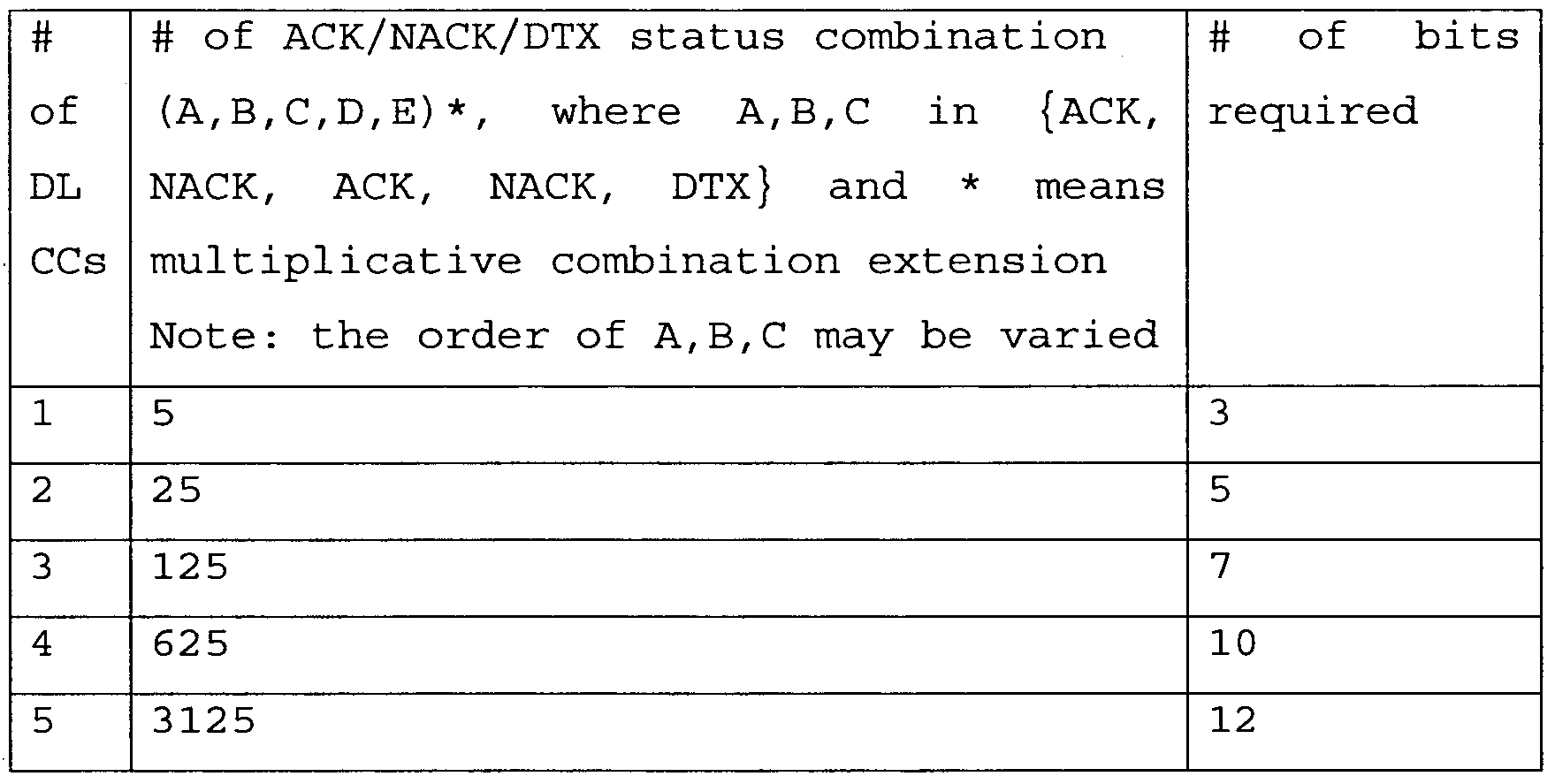
If the base station performs MIMO transmission, 5ΛNcc number of states may occur. The number of states that can occur depending on the number of component carriers and bits required to express the states are illustrated in Table 10 below. Also, Table 11 illustrates an example of ACK/NACK/DTX information expressed depending on the above method .
[Table 10]
Figure imgf000039_0001
[Table 11]
Figure imgf000039_0002
Figure imgf000040_0001
Figure imgf000041_0001
Likewise, although the number of component carriers is 2 in Table 11, even if the number of component carriers is 3 or more, extension can be performed in the same manner as Table 11. Meanwhile, these bit indexes can be transmitted through payload of PUCCH format 2. In this case, the same scheme as that of the related art in which CQI is transmitted can be used as a channel coding and modulation scheme . Meanwhile, a transmission mode may be defined for each component carrier. In this case, ACK/NACK/DTX information that can occur for each component carrier can become three states or five states. These two types of states may be used together, or the three states may be added to the five states.
For example, if all downlink component carriers use non-MIMO transmission mode, transmission is performed depending on definition of Table 9. If any one or more downlink component carriers are defined in a MIMO transmission mode, bit index mapping of all downlink component carriers is defined depending on Table 11. In this case, in case of non-MIMO transmission mode, for mapping, three states should be converted to five states. In this case, conversion can be performed in such a manner as DTX -> DTX, ACK -> ACK/ACK and NACK -> NACK/NACK.
Unlike this, since a transmission mode and setup information of each downlink component carrier can be sued by the user equipment, the method for transmitting ACK/NACK/DTX by performing bit index mapping for each downlink component carrier and performing joint coding may be considered. Hereinafter, a method for allocating resources when ACK/NACK information is transmitted using PUCCH format 2 will be described. First of all, the base station can directly indicate whether to use PUCCH format 2 for ACK/NACK information transmission through upper layer, for example, RRC layer.
Alternatively, the base station may indirectly indicate information of dedicated resource allocation for PUCCH format 2 through RRC layer. For example, the base station may indicate that PUCCH format 2 can be used in a specific component carrier, or may forward a value designating location of dedicated resource used by PUCCH format 2 or a parameter related to the value. The other resources mapped into PUCCH format 2 and PUCCH format 1 of the LTE system can be used as the PUCCH format 2 dedicated resources for ACK/NACK information transmission within an uplink component carrier.
FIG. 17 is a diagram illustrating a method for allocating PUCCH format 2 dedicated resources according to one embodiment of the present invention. As shown in FIG. 17, in LTE ReI -8 PUCCH, PUCCH format 2 that transmits CQI is located at the edge of RB, PUCCH format 2a or PUCCH format 2b that transmits CQI+ ACK/NACK is located next to the edge, and ACK/NACK is mapped into the PUCCH format 2a or the PUCCH format 2b. For compatibility with the related art system, PUCCH format 2 for ACK/NACK transmission of the present invention is transmitted to next part to a resource to which ReI -8 PUCCH is transmitted.
Meanwhile, if there is resource allocated for LTE-A, PUCCH format 2 for ACK/NACK transmission may be transmitted from the corresponding part only. FIG. 18 is a diagram illustrating an example of using a PUCCH format 2 dedicated resource allocated as a resource for LTE-A in accordance with one embodiment of the present invention.
Also, PUCCH format 2 for existing CQI resource may be used again instead of allocating the dedicated resource. In this case, a PUCCH allocation scheme for transmitting CQI or CQI+ACK/NACK can be used.
Hereinafter, another method for transmitting ACK/NACK information will be described.
FIG. 19 is a diagram illustrating another method for transmitting ACK/NACK information in accordance with one embodiment of the present invention. In particular, unlike
FIG. 10 or FIG. 11, FIG. 19 illustrates that message pairing is not applied.
Referring to FIG. 19, each OFDM symbol can be used to transmit ACK/NACK information of one component carrier. OFDM symbols for reference signal transmission will be excluded.
In case of normal CP, since two OFDM symbols (S2 and S6) per slot are used as reference symbols, the other OFDM symbols can be used data symbols for transmitting ACK/NACK information. If one reference symbol per slot is used, S4 can be used as a reference symbol and the other six data symbols can be used to transmit ACK/NACK information.
In case of extended CP, two reference symbols per slot may be used, or one reference symbol per slot may be used. Likewise, the other data symbols except for the reference symbols can be used to transmit ACK/NACK information.
Each of the symbols for transmitting ACK/NACK information can be used as a PUCCH corresponding to one downlink component carrier. For example, when the user equipment should transmit ACK/NACK signals of N number of downlink component carriers, the user equipment can map downlink component carriers in due order by starting from Sl. For example, it is assumed that ACK/NACK signals for five downlink component carriers are transmitted. In case of normal CP, the user equipment can map ACK/NACK signal of each downlink component carrier into five data symbols of the first slot .
If the number of downlink component carriers for ACK/NACK information transmission is more than the number of data symbols that can be transmitted from one slot, symbols from a neighboring slot can be used additionally as much as wanted symbols regardless of hopping.
In this case, one data symbol transmits ACK/NACK information of one component carrier through a specific modulation scheme (BPSK, QPSK, 8PSK, or 16QAM) . The data symbols may be mapped in due order depending on component carrier indexes or in a type of constant offset .
In one subframe, remaining data symbols, i.e., data symbols, which have been used during the first ACK/NACK signal transmission, can repeatedly be allocated to ACK/NACK information. The mapping order of data symbols and the mapping order of ACK/NACK information can be varied. In this case, masking sequence such as walsh code, DFT, ZC sequence, and m-sequence can be applied between the repeated symbols, whereby spreading gain can be obtained.
Meanwhile, if repetition of ACK/NACK information of a specific component carrier is greater than repetition of ACK/NACK information of another component carrier, the ACK/NACK information repeated for the specific component carrier can be subjected to truncation in due order which is previously defined.
The number of component carriers which should transmit ACK/NACK information can be defined depending on the number of component carriers specified by the user equipment. However, how much ACK/NACK information should be transmitted can be notified directly by scheduling grant. Alternatively, the number of component carriers can be indicated through a specific control channel to indirectly indicate how much ACK/NACK information should be transmitted .
Some data symbols may not be used for repetition of ACK/NACK information but be used to mean the state (DTX) where a control signal is not received. At this time, the last symbol location of the second slot can first be selected as the location of DTX by considering location of a sounding reference signal. Alternatively, DTX may be expressed in a type where symbol is not transmitted.
An example of another method for transmitting ACK/NACK information according to the aforementioned embodiment of the present invention will be described in detail. First of all, it is assumed that the base station transmits transport blocks using five downlink component carriers .
FIG. 20 is a diagram illustrating an example of transmitting ACK/NACK information according to one embodiment of the present invention in case of normal CP. In FIG. 20, dO to d4 correspond to numbers of downlink component carriers. Namely, it means that ACK/NACK information of downlink component carrier #0 is dO, and ACK/NACK information of downlink component carrier #1 is dl . At this time, BPSK or QPSK can be applied to dO to d4. Modulation schemes applied to ACK/NACK information are independent from each another. Namely, BPSK may be applied to dθ~dl while QPSK may be applied to d2~d4. Likewise, FIG. 21 is a diagram illustrating an example of transmitting ACK/NACK information according to one embodiment of the present invention in case of extended CP. Also, ACK/NACK information of a specific downlink component carrier can only be repeated. FIG. 22 is a diagram illustrating a case where ACK/NACK information of a specific downlink component carrier is repeated.
Referring to FIG. 22, if the number of downlink component carriers is four (DL CC#0-3) , ACK/NACK information of DL CC#3 can be repeated. In this case, it is preferable that the repeated ACK/NACK information d3 of DL CC#3 represents DTX.
The DTX can be expressed depending on transmission of corresponding data symbols. For example, if data symbols corresponding to a corresponding downlink component carrier are transmitted, it means that ACK/NACK is transmitted. If the data symbols are not transmitted, it can be set that DTX is transmitted. FIG. 23 is a diagram illustrating a base station and a user equipment that can be applied to the embodiment of the present invention.
Referring to FIG. 23, the wireless communication system includes a base station (BS) 2310 and a user equipment (UE) 2320. In the downlink, the transmitter is a part of the base station 2310 and the receiver is a part of the user equipment 2320. In the uplink, the transmitter is a part of the user equipment 2320 and the receiver is a part of the base station 2310. The base station 2310 includes a processor 2312, a memory 2314, and a radio frequency (RF) unit 2316. The processor 2312 can be configured to implement procedures and/or methods suggested in the present invention. The memory 2314 is connected with the processor 2312 and stores various kinds of information related to the operation of the processor 2312. The RF unit 2316 is connected with the processor 2312 and transmits and/or receives a radio signal. Namely, the RF unit 2316 includes a transmitting module and receiving module.
The user equipment 2320 includes a processor 2322, a memory 2324, and a radio frequency (RF) unit 2326. The processor 2322 can be configured to implement procedures and/or methods suggested in the present invention. The memory 2324 is connected with the processor 2322 and stores various kinds of information related to the operation of the processor 2322. The RF unit 2326 is connected with the processor 2322 and transmits and/or receives a radio signal. Namely, the RF unit 2326 includes a transmitting module and receiving module .
The base station 2310 and/or the user equipment 2320 can have a single antenna or multiple antennas. The aforementioned embodiments are achieved by combination of structural elements and features of the present invention in a predetermined type. Each of the structural elements or features should be considered selectively unless specified separately. Each of the structural elements or features may be carried out without being combined with other structural elements or features. Also, some structural elements and/or features may be combined with one another to constitute the embodiments of the present invention. The order of operations described in the embodiments of the present invention may be changed.
Some structural elements or features of one embodiment may be included in another embodiment, or may be replaced with corresponding structural elements or features of another embodiment. Moreover, it will be apparent that some claims referring to specific claims may be combined with another claims referring to the other claims other than the specific claims to constitute the embodiment or add new claims by means of amendment after the application is filed.
The embodiments of the present invention have been described based on the data transmission and reception between the base station and the user equipment. A specific operation which has been described as being performed by the base station may be performed by an upper node of the base station as the case may be. In other words, it will be apparent that various operations performed for communication with the user equipment in the network which includes a plurality of network nodes along with the base station can be performed by the base station or network nodes other than the base station. The base station may be replaced with terms such as a fixed station, Node B, eNode B (eNB) , and access point. Also, the user equipment may be replaced with terms such as mobile station (MS) and mobile subscriber station (MSS) .
The embodiments according to the present invention can be implemented by various means, for example, hardware, firmware, software, or their combination. If the embodiment according to the present invention is implemented by hardware, the embodiment of the present invention can be implemented by one or more application specific integrated circuits (ASICs) , digital signal processors (DSPs) , digital signal processing devices (DSPDs) , programmable logic devices (PLDs) , field programmable gate arrays (FPGAs) , processors, controllers, microcontrollers, microprocessors, etc. If the embodiment according to the present invention is implemented by firmware or software, the embodiment of the present invention may be implemented by a type of a module, a procedure, or a function, which performs functions or operations described as above. A software code may be stored in a memory unit and then may be driven by a processor. The memory unit may be located inside or outside the processor to transmit and receive data to and from the processor through various means which are well known. It will be apparent to those skilled in the art that the present invention can be embodied in other specific forms without departing from the spirit and essential characteristics of the invention. Thus, the above embodiments are to be considered in all respects as illustrative and not restrictive. The scope of the invention should be determined by reasonable interpretation of the appended claims and all change which comes within the equivalent scope of the invention are included in the scope of the invention. [industrial Applicability]
The present invention can be applied to a wireless communication system. More specifically, the present invention can be applied to a method and apparatus for transmitting ACK/NACK information in a wireless communication system to which carrier aggregation is applied.

Claims

[CLAIMS]
[Claim l]
A method for transmitting ACK/NACK (Acknowledgement/Negative ACK) signals in a wireless communication system, the method comprising: receiving a plurality of data blocks from a base station; generating ACK/NACK signals corresponding to the plurality of data blocks; allocating resources for transmitting the ACK/NACK signals, wherein the resources are allocated independently per slot; and transmitting the ACK/NACK signals through one uplink component carrier by using the allocated resources. [Claim 2]
The method of claim 1, wherein the plurality of data blocks are received at the same time through a plurality of downlink component carriers. [Claim 3] The method of claim 1, wherein the step of allocating resources includes allocating the resources to minimize the difference in the number of the ACK/NACK signals transmitted per slot.
[Claim 4] The method of claim 1, wherein the step of receiving a plurality of data blocks includes receiving two or more data blocks through at least one downlink component carrier among the plurality of downlink component carriers.
[Claim 5] A method for transmitting ACK/NACK
(Acknowledgement/Negative ACK) signals in a wireless communication system, the method comprising: receiving a plurality of data blocks through a plurality of downlink component carriers from a base station; generating ACK/NACK signals corresponding to the plurality of data blocks; mapping the ACK/NACK signals into a bit index; allocating control channel resources for transmitting the bit index; and transmitting the bit index through one uplink component carrier by using the allocated control channel resources . [Claim 6]
The method of claim 5, wherein the control channel resources are payload of PUCCH (physical uplink control channel) format 2. [Claim 7]
A method for transmitting ACK/NACK (Acknowledgement/Negative ACK) signals in a wireless communication system, the method comprising: receiving a plurality of data blocks through a plurality of downlink component carriers from a base station; generating ACK/NACK signals corresponding to the plurality of data blocks; allocating containers for transmitting the ACK/NACK signals in control channel resources in accordance with an index order of the downlink component carriers as much as the received data blocks ; and transmitting the ACK/NACK signals through one uplink component carrier by using the allocated containers. [Claim 8]
The method of claim 7, wherein the control channel resources are payload of PUCCH (physical uplink control channel) format 2. [Claim S>1
The method of claim 7, wherein the step of receiving a plurality of data blocks includes receiving two or more data blocks through at least one downlink component carrier among the plurality of downlink component carriers, wherein the step of allocating containers includes allocating the containers in accordance with the order of the data blocks received through the at least one downlink component carrier. [Claim lθ]
A user equipment comprising: a receiving module receiving a plurality of data blocks from a base station; a processor generating ACK/NACK signals corresponding to the plurality of data blocks and allocating resources for transmitting the ACK/NACK signals, wherein the resources are allocated independently per slot; and a transmitting module transmitting the ACK/NACK signals through one uplink component carrier by using the allocated resources. [Claim ll]
The user equipment of claim 10, wherein the receiving module receives the plurality of data blocks at the same time through a plurality of downlink component carriers. [Claim 12]
The user equipment of claim 10, wherein the processor allocates the resources to minimize the difference in the number of the ACK/NACK signals transmitted per slot. [Claim 13]
The user equipment of claim 11, wherein the receiving module receives two or more data blocks through at least one downlink component carrier among the plurality of downlink component carriers. [Claim 14]
A user equipment comprising: a receiving module receiving a plurality of data blocks at the same time through a plurality of downlink component carriers from a base station; a processor generating ACK/NACK signals corresponding to the plurality of data blocks, mapping the ACK/NACK signals into a bit index, and allocating control channel resources for transmitting the bit index; and a transmitting module transmitting the bit index through one uplink component carrier by using the allocated control channel resources . [Claim 15]
The user equipment of claim 14, wherein the control channel resources are payload of PUCCH (physical uplink control channel) format 2.
[Claim 16] A user equipment comprising: a receiving module receiving a plurality of data blocks at the same time through a plurality of downlink component carriers from a base station; a processor generating ACK/NACK signals corresponding to the plurality of data blocks and allocating containers for transmitting the ACK/NACK signals in control channel resources in accordance with an index order of the downlink component carriers as much as the received data blocks; and a transmitting module transmitting the ACK/NACK signals through one uplink component carrier by using the allocated containers. [Claim 17]
The user equipment of claim 16, wherein the control channel resources are payload of PUCCH (physical uplink control channel) format 2. [Claim 18]
The user equipment of claim 16, wherein the receiving module receives a plurality of data blocks includes receiving two or more data blocks through at least one downlink component carrier among the plurality of downlink component carriers, wherein the processor allocates the containers in accordance with the order of the data blocks received through the at least one downlink component carrier.
PCT/KR2010/001810 2009-03-29 2010-03-24 Method for transmitting control information in wireless communication system and apparatus therefor WO2010114252A2 (en)

Priority Applications (12)

Application Number Priority Date Filing Date Title
CN201080014088.2A CN102365837B (en) 2009-03-29 2010-03-24 Method for transmitting control information in wireless communication system and apparatus therefor
US13/254,323 US9401779B2 (en) 2009-03-29 2010-03-24 Method for transmitting control information in wireless communication system and apparatus therefor
KR1020117018686A KR101186619B1 (en) 2009-03-29 2010-03-24 Method for trasmitting control information in wireless communication system and apparatus therefor
US14/553,771 US9401780B2 (en) 2009-03-29 2014-11-25 Method for transmitting control information in wireless communication system and apparatus therefor
US14/553,837 US9525518B2 (en) 2009-03-29 2014-11-25 Method for transmitting control information in wireless communication system and apparatus therefor
US15/357,485 US9742545B2 (en) 2009-03-29 2016-11-21 Method for transmitting control information in wireless communication system and apparatus therefor
US15/658,979 US10063360B2 (en) 2009-03-29 2017-07-25 Method for transmitting control information in wireless communication system and apparatus therefor
US16/049,270 US10211963B2 (en) 2009-03-29 2018-07-30 Method for transmitting control information in wireless communication system and apparatus therefor
US16/239,168 US10505693B2 (en) 2009-03-29 2019-01-03 Method for transmitting control information in wireless communication system and apparatus therefor
US16/708,225 US10911206B2 (en) 2009-03-29 2019-12-09 Method for transmitting control information in wireless communication system and apparatus therefor
US16/877,718 US10855431B2 (en) 2009-03-29 2020-05-19 Method for transmitting control information in wireless communication system and apparatus therefor
US17/156,098 US11546118B2 (en) 2009-03-29 2021-01-22 Method for transmitting control information in wireless communication system and apparatus therefor

Applications Claiming Priority (6)

Application Number Priority Date Filing Date Title
US16446109P 2009-03-29 2009-03-29
US61/164,461 2009-03-29
US17220109P 2009-04-23 2009-04-23
US61/172,201 2009-04-23
US17728609P 2009-05-12 2009-05-12
US61/177,286 2009-05-12

Related Child Applications (3)

Application Number Title Priority Date Filing Date
US13/254,323 A-371-Of-International US9401779B2 (en) 2009-03-29 2010-03-24 Method for transmitting control information in wireless communication system and apparatus therefor
US14/553,837 Continuation US9525518B2 (en) 2009-03-29 2014-11-25 Method for transmitting control information in wireless communication system and apparatus therefor
US14/553,771 Continuation US9401780B2 (en) 2009-03-29 2014-11-25 Method for transmitting control information in wireless communication system and apparatus therefor

Publications (2)

Publication Number Publication Date
WO2010114252A2 true WO2010114252A2 (en) 2010-10-07
WO2010114252A3 WO2010114252A3 (en) 2011-01-13

Family

ID=42828813

Family Applications (1)

Application Number Title Priority Date Filing Date
PCT/KR2010/001810 WO2010114252A2 (en) 2009-03-29 2010-03-24 Method for transmitting control information in wireless communication system and apparatus therefor

Country Status (4)

Country Link
US (10) US9401779B2 (en)
KR (1) KR101186619B1 (en)
CN (1) CN102365837B (en)
WO (1) WO2010114252A2 (en)

Cited By (9)

* Cited by examiner, † Cited by third party
Publication number Priority date Publication date Assignee Title
US8270364B1 (en) 2011-06-06 2012-09-18 Renesas Mobile Corporation Method, apparatus and computer program for wireless communication
WO2013067693A1 (en) * 2011-11-09 2013-05-16 Renesas Mobile Corporation Effective dealing with restricted transmission power in carrier aggregation scenarios
CN103229446A (en) * 2010-11-24 2013-07-31 Lg电子株式会社 Method and user equipment for transmitting uplink control information, and method and base station for receiving uplink control information
EP2901602A1 (en) * 2012-09-28 2015-08-05 Intel Corporation TRANSMISSION OF UPLINK CONTROL INFORMATION IN INTER-eNB CARRIER AGGREGATION
CN105406944A (en) * 2011-02-15 2016-03-16 Lg电子株式会社 Method And Apparatus For Transmitting Channel Quality Control Information In Wireless Access System
CN107204835A (en) * 2011-05-31 2017-09-26 三星电子株式会社 Define the device and method thereof of physical channel transmission/reception timing and resource allocation
EP2675227A4 (en) * 2011-02-07 2017-12-13 Ntt Docomo, Inc. User terminal, wireless base station device and wireless communication method
EP3253100A4 (en) * 2015-01-29 2018-09-12 NTT DoCoMo, Inc. User terminal, wireless base station, and wireless communication method
CN113938244A (en) * 2020-06-29 2022-01-14 海能达通信股份有限公司 Transmission method of communication response signal, base station and terminal

Families Citing this family (44)

* Cited by examiner, † Cited by third party
Publication number Priority date Publication date Assignee Title
ES2377818T3 (en) * 2005-12-14 2012-04-02 Research In Motion Limited Method and apparatus for the control of radio resources directed to a user equipment in a UMTS network
DE602006017517D1 (en) * 2006-05-17 2010-11-25 Research In Motion Ltd Method and system for indicating a cause for a degradation of a signaling connection in a UMTS network
US8265034B2 (en) 2006-05-17 2012-09-11 Research In Motion Limited Method and system for a signaling connection release indication
US20080049662A1 (en) * 2006-08-25 2008-02-28 Research In Motion Limited Apparatus, and associated method, for releasing a data-service radio resource allocated to a data-service-capable mobile node
KR101493990B1 (en) 2007-08-13 2015-02-16 고도 가이샤 아이피 브릿지 1 Radio transmission device and radio transmission method
US8208950B2 (en) 2007-11-13 2012-06-26 Research In Motion Limited Method and apparatus for state/mode transitioning
KR101638900B1 (en) * 2008-08-05 2016-07-12 엘지전자 주식회사 Method of transmitting control information information of downlink multi carriers in a wireless communication system
KR101253190B1 (en) 2008-08-08 2013-04-10 엘지전자 주식회사 Method of reporting a channel quality information and assigning radio resource accordign to the channel quality information in a wireless communication system
EP2356878B1 (en) * 2008-11-10 2015-07-29 BlackBerry Limited Method and apparatus of transition to a battery efficient state or configuration by indicating end of data transmission in long term evolution
CN102365837B (en) 2009-03-29 2014-05-14 Lg电子株式会社 Method for transmitting control information in wireless communication system and apparatus therefor
KR101695873B1 (en) * 2009-06-25 2017-01-13 코닌클리케 필립스 엔.브이. A method for communicating in a mobile network
AU2010321205B2 (en) 2009-11-23 2014-09-04 Blackberry Limited State or mode transition triggering based on SRI message transmission
SG191601A1 (en) 2009-11-23 2013-07-31 Research In Motion Ltd Method and apparatus for state/mode transitioning
AU2010321204B2 (en) 2009-11-23 2014-11-20 Blackberry Limited Method and apparatus for state/mode transitioning
US8983532B2 (en) * 2009-12-30 2015-03-17 Blackberry Limited Method and system for a wireless communication device to adopt varied functionalities based on different communication systems by specific protocol messages
EP3393075B1 (en) * 2010-01-18 2020-07-15 Telefonaktiebolaget LM Ericsson (publ) Radio base station and user equipment and methods therein
JP5449409B2 (en) * 2010-01-28 2014-03-19 パナソニック株式会社 Control information transmitting apparatus, control information receiving apparatus, and control information transmitting method
AU2010345442A1 (en) * 2010-02-10 2012-06-28 Blackberry Limited Method and apparatus for state/mode transitioning
KR101802518B1 (en) * 2010-03-03 2017-11-29 엘지전자 주식회사 Method and apparatus of transmitting uplink conrtol information in wireless communication system
ES2681020T3 (en) 2010-03-22 2018-09-11 Samsung Electronics Co., Ltd Multiplexing control and data information from a user equipment in a physical data channel
CN102255696B (en) * 2010-04-07 2016-03-30 华为技术有限公司 A kind of method of transmitting uplink control information, subscriber equipment and base station
US8942199B2 (en) 2010-05-06 2015-01-27 Panasonic Intellectual Property Corporation Of America Terminal apparatus and response signal mappiing method
WO2011142552A2 (en) * 2010-05-08 2011-11-17 Lg Electronics Inc. Error propagation protection in non-binary multiple ack/nacks
JP2012005075A (en) * 2010-06-21 2012-01-05 Ntt Docomo Inc Mobile terminal device and radio communication method
EP2612458B1 (en) 2010-09-01 2018-02-21 Sharp Kabushiki Kaisha Joint coding method based on binary tree and coder
KR101470266B1 (en) * 2010-09-20 2014-12-05 후지쯔 가부시끼가이샤 Method for transmitting uplink response signals, base station, mobile station and communication system
AU2011324151B2 (en) * 2010-11-03 2016-02-25 Samsung Electronics Co., Ltd. Method and apparatus for coding of HARQ-ACK transmission in TDD systems with DownLink carrier aggregation
US9723592B2 (en) 2011-10-13 2017-08-01 Lg Electronics Inc. Method and user equipment for transmitting uplink signal, and method and evolved node B for receiving uplink signal
CA2823789C (en) 2011-11-11 2016-08-16 Research In Motion Limited Method and apparatus for user equipment state transition
CN104704763B (en) * 2012-09-06 2017-12-12 Lg 电子株式会社 Terminal is set to send the method and its device of ul ack/NACK signal in the wireless communication system using carrier aggregation technology
EP3217588B1 (en) * 2014-11-05 2020-02-26 LG Electronics Inc. Method and device for allocating resource unit on basis of container in wireless lan
WO2016122390A2 (en) * 2015-01-30 2016-08-04 Telefonaktiebolaget Lm Ericsson (Publ) Harq ack/nack bundling of feca
KR102607061B1 (en) * 2015-06-04 2023-11-29 한국전자통신연구원 Method and apparatus for receiving data, and method for transmitting data in mobile communication system
KR102202325B1 (en) 2015-11-04 2021-01-14 인터디지탈 패튼 홀딩스, 인크 Method and procedure for narrowband LTE operation
CN111082915B (en) * 2016-08-14 2022-05-31 上海朗帛通信技术有限公司 Method and device in wireless communication
AU2017351791B2 (en) * 2016-10-28 2020-12-03 Telefonaktiebolaget Lm Ericsson (Publ) Receiver-specific transmission length
AU2018246779B2 (en) 2017-03-25 2020-01-02 Lg Electronics Inc. Method for PTRS reception for phase noise cancellation in wireless communication system, and device therefor
KR20200012842A (en) 2017-05-03 2020-02-05 아이디에이씨 홀딩스, 인크. Method, system, and apparatus for transmitting uplink control information
CN109451794B (en) * 2017-07-19 2020-01-14 北京小米移动软件有限公司 Method and device for transmitting information
CN109937589B (en) 2017-08-11 2021-03-23 华为技术有限公司 Method and apparatus for transmitting and receiving data
US11438881B2 (en) * 2017-10-23 2022-09-06 Qualcomm Incorporated Techniques and apparatuses for modulation order control for an uplink channel
CN113490285B (en) * 2018-04-04 2022-12-06 中兴通讯股份有限公司 Transmission method and device and computer readable storage medium
CN109493803B (en) 2018-10-29 2021-01-08 惠科股份有限公司 Driving method and driving device of display panel and display device
US11012211B2 (en) * 2019-10-07 2021-05-18 Jaihyung Cho Method for transmitting reference signal and apparatus using the same

Citations (4)

* Cited by examiner, † Cited by third party
Publication number Priority date Publication date Assignee Title
KR20070011030A (en) * 2005-07-20 2007-01-24 삼성전자주식회사 System and method for transmitting/receiving hybrid automatic repeat request map information element in a broadband wireless access communication system
KR20080096088A (en) * 2007-04-26 2008-10-30 삼성전자주식회사 Method and apparatus for allocating response channel resource in wireless telecommunication system
KR20090017408A (en) * 2007-08-14 2009-02-18 엘지전자 주식회사 Method of transmitting data in a wireless communication system
KR20090019662A (en) * 2007-08-21 2009-02-25 삼성전자주식회사 Method and apparatus for transmitting ack/nack signal in mobile communication system

Family Cites Families (53)

* Cited by examiner, † Cited by third party
Publication number Priority date Publication date Assignee Title
JP2006050519A (en) * 2003-10-24 2006-02-16 Sony Corp Wireless communications system, wireless communications apparatus, wireless communication method, and computer program
KR20050081528A (en) * 2004-02-14 2005-08-19 삼성전자주식회사 Channel state information feedback method for multi-carrier communication system
JP4440037B2 (en) 2004-08-11 2010-03-24 株式会社東芝 Communication apparatus and communication method
KR100946875B1 (en) * 2006-12-21 2010-03-09 삼성전자주식회사 Apparatus and method for transmitting/receiving data in a communication system
KR101049138B1 (en) * 2007-03-19 2011-07-15 엘지전자 주식회사 In a mobile communication system, an acknowledgment signal receiving method
CN101272179A (en) * 2007-03-23 2008-09-24 Nxp股份有限公司 Method for wireless communication, subscriber station and base station
US20080232307A1 (en) * 2007-03-23 2008-09-25 Zhouyue Pi Method and apparatus to allocate resources for acknowledgments in communication systems
KR20090011966A (en) 2007-07-27 2009-02-02 주식회사 하이닉스반도체 Stack package and method for fabricating of the same
EP3293905B1 (en) 2007-08-14 2021-02-17 LG Electronics Inc. Method for acquiring resource region information for phich
JP4835598B2 (en) 2007-08-21 2011-12-14 富士ゼロックス株式会社 Cleaning device, image forming apparatus, and image carrier unit
CN101505208A (en) * 2008-02-04 2009-08-12 三星电子株式会社 Method for allocating uplink ACK/NACK channel
US7957329B2 (en) * 2008-03-16 2011-06-07 Lg Electronics Inc. Method of performing hybrid automatic repeat request (HARQ) in wireless communication system
US8537853B2 (en) 2008-03-20 2013-09-17 Telefonaktiebolaget Lm Ericsson (Publ) Side information bits of ACK and NACK bits in multiple ACK/NACK transmission
KR101638900B1 (en) 2008-08-05 2016-07-12 엘지전자 주식회사 Method of transmitting control information information of downlink multi carriers in a wireless communication system
WO2010016750A2 (en) * 2008-08-07 2010-02-11 엘지전자주식회사 Method and apparatus for performing a harq operation in a multi-carrier system
US7924754B2 (en) * 2008-09-23 2011-04-12 Telefonaktiebolaget L M Ericsson Multiple carrier acknowledgment signaling
EP2332356B1 (en) 2008-09-23 2017-09-06 Telefonaktiebolaget LM Ericsson (publ) Rlc segmentation for carrier aggregation
AR073833A1 (en) * 2008-10-20 2010-12-01 Interdigital Patent Holdings METHODS FOR THE ASCENDING CONTROL OF INFORMATION TRANSMISSION TO ADD CARRIER ONA
WO2010050754A2 (en) * 2008-10-29 2010-05-06 엘지전자 주식회사 Method for efficiently transmitting physical channel in multi-carrier aggregation state to support broadband
KR101648775B1 (en) 2008-10-30 2016-08-17 엘지전자 주식회사 Method of harq acknowledgement transmission and transport block retransmission in a wireless communication system
WO2010050766A2 (en) * 2008-10-31 2010-05-06 엘지전자주식회사 Method and apparatus for performing harq process in wireless communication system
EP2357735B1 (en) * 2008-11-14 2016-11-09 LG Electronics Inc. Method and apparatus for information transmission in wireless communication system
KR101711864B1 (en) 2008-12-23 2017-03-03 엘지전자 주식회사 Uplink ack/nack signalling in carrier aggregation environment
KR20100073992A (en) * 2008-12-23 2010-07-01 엘지전자 주식회사 Uplink transmission in carrier aggregation environment
KR20110138421A (en) * 2008-12-30 2011-12-27 인터디지탈 패튼 홀딩스, 인크 Control channel feedback for multiple downlink carrier operations
US20100172308A1 (en) 2009-01-07 2010-07-08 Samsung Electronics Co., Ltd. System and method for downlink physical indicator channel mapping with asymmetric carrier aggregation
US8565066B2 (en) * 2009-01-08 2013-10-22 Samsung Electronics Co., Ltd. System and method for an uplink acknowledgement transmission in carrier-aggregated wireless communication systems
EP2380388A1 (en) * 2009-01-16 2011-10-26 Telefonaktiebolaget LM Ericsson (publ) Method and apparatus for pucch load control by pdcch restrictions
JP5928873B2 (en) 2009-02-03 2016-06-01 ノキア ソリューションズ アンド ネットワークス オサケユキチュア Apparatus, method and product
CN102422583B (en) * 2009-03-11 2015-02-18 三星电子株式会社 Method and device for user equipment transmitting bit acknowledgement associated to HARQ
EP2675232B1 (en) * 2009-03-12 2019-01-16 Interdigital Patent Holdings, Inc. Method and apparatus for selecting and reselecting an uplink primary carrier
AU2010226635B2 (en) * 2009-03-17 2014-06-12 Samsung Electronics Co., Ltd. Uplink transmission power control in multi-carrier communication systems
US8345614B2 (en) * 2009-03-17 2013-01-01 Qualcomm Incorporated Single channelization code HARQ feedback for DC-HSDPA +MIMO
KR101749346B1 (en) * 2009-03-25 2017-06-21 엘지전자 주식회사 Method and apparatus for performing harq in multiple carrier system
CN102365837B (en) 2009-03-29 2014-05-14 Lg电子株式会社 Method for transmitting control information in wireless communication system and apparatus therefor
KR101759933B1 (en) 2009-05-07 2017-07-20 엘지전자 주식회사 Method and appratus of transmitting ack/nack
EP2293486A1 (en) 2009-09-03 2011-03-09 Panasonic Corporation Feedback scheme for providing feedback on plural transmissions
US9379851B2 (en) * 2009-10-20 2016-06-28 Lg Electronics Inc. Method and apparatus for transmitting acknowledgement in wireless communication system
KR101334536B1 (en) * 2009-10-26 2013-11-28 엘지전자 주식회사 Method and apparatus for transmitting reception acknowledgement information in wireless communication system
CN102511035A (en) * 2009-11-09 2012-06-20 莫维克网络公司 Burst packet scheduler for improved RAN efficiency in UMTS/HSPA networks
KR101328213B1 (en) * 2010-02-12 2013-11-14 엘지전자 주식회사 Method and apparatus of transmitting data in wireless communication system
ES2681020T3 (en) * 2010-03-22 2018-09-11 Samsung Electronics Co., Ltd Multiplexing control and data information from a user equipment in a physical data channel
US8555128B2 (en) 2010-03-24 2013-10-08 Futurewei Technologies, Inc. System and method for transmitting and receiving acknowledgement information
CN103929288B (en) 2010-06-16 2017-06-06 Lg电子株式会社 Send the method and its equipment of control information
WO2012044082A1 (en) * 2010-09-29 2012-04-05 엘지전자 주식회사 Method and apparatus for transmitting multiple reception confirmations in time division duplex system
AU2011324151B2 (en) 2010-11-03 2016-02-25 Samsung Electronics Co., Ltd. Method and apparatus for coding of HARQ-ACK transmission in TDD systems with DownLink carrier aggregation
CN102594493B (en) * 2011-01-17 2014-08-20 华为技术有限公司 Response message encoding, process method and device
WO2012110493A1 (en) 2011-02-14 2012-08-23 Nokia Siemens Networks Oy Multiplexing of ack/nack and channel state information on uplink control channel
CN102752085B (en) * 2011-04-21 2014-09-17 华为技术有限公司 Method and equipment for sending acknowledgement or non-acknowledgement indication information in time division duplexing (TDD) system
CN103516499B (en) * 2012-06-19 2017-06-13 电信科学技术研究院 A kind of ACK/NACK number of bits of feedback determines method and device
US9258741B2 (en) 2012-08-03 2016-02-09 Blackberry Limited Carrier aggregation acknowledgement bits
US10687316B2 (en) * 2014-07-17 2020-06-16 Qualcomm Incorporated Techniques for enabling component carriers for multi-carrier wireless communication
WO2016185641A1 (en) * 2015-05-15 2016-11-24 日本電気株式会社 Device and method for harq ack/nack bits transmission

Patent Citations (4)

* Cited by examiner, † Cited by third party
Publication number Priority date Publication date Assignee Title
KR20070011030A (en) * 2005-07-20 2007-01-24 삼성전자주식회사 System and method for transmitting/receiving hybrid automatic repeat request map information element in a broadband wireless access communication system
KR20080096088A (en) * 2007-04-26 2008-10-30 삼성전자주식회사 Method and apparatus for allocating response channel resource in wireless telecommunication system
KR20090017408A (en) * 2007-08-14 2009-02-18 엘지전자 주식회사 Method of transmitting data in a wireless communication system
KR20090019662A (en) * 2007-08-21 2009-02-25 삼성전자주식회사 Method and apparatus for transmitting ack/nack signal in mobile communication system

Cited By (18)

* Cited by examiner, † Cited by third party
Publication number Priority date Publication date Assignee Title
CN103229446B (en) * 2010-11-24 2016-04-13 Lg电子株式会社 Transmit the method for uplink control information and subscriber equipment, and the method for receiving uplink control information and base station
CN103229446A (en) * 2010-11-24 2013-07-31 Lg电子株式会社 Method and user equipment for transmitting uplink control information, and method and base station for receiving uplink control information
US9577810B2 (en) 2010-11-24 2017-02-21 Lg Electronics Inc. Method and user equipment for transmitting uplink control information, and method and base station for receiving uplink control information
US9307525B2 (en) 2010-11-24 2016-04-05 Lg Electronics Inc. Method and user equipment for transmitting uplink control information, and method and base station for receiving uplink control information
EP2675227A4 (en) * 2011-02-07 2017-12-13 Ntt Docomo, Inc. User terminal, wireless base station device and wireless communication method
CN105406944B (en) * 2011-02-15 2019-03-15 Lg电子株式会社 The method and apparatus of channel quality control information are sent in wireless access system
CN105406944A (en) * 2011-02-15 2016-03-16 Lg电子株式会社 Method And Apparatus For Transmitting Channel Quality Control Information In Wireless Access System
CN107204835A (en) * 2011-05-31 2017-09-26 三星电子株式会社 Define the device and method thereof of physical channel transmission/reception timing and resource allocation
GB2491815B (en) * 2011-06-06 2013-12-18 Renesas Mobile Corp Method, apparatus and computer program for wireless communication
US8270364B1 (en) 2011-06-06 2012-09-18 Renesas Mobile Corporation Method, apparatus and computer program for wireless communication
GB2491815A (en) * 2011-06-06 2012-12-19 Renesas Mobile Corp Sending feedback reports in a wireless communication system using carrier aggregation
WO2013067693A1 (en) * 2011-11-09 2013-05-16 Renesas Mobile Corporation Effective dealing with restricted transmission power in carrier aggregation scenarios
EP2901602A1 (en) * 2012-09-28 2015-08-05 Intel Corporation TRANSMISSION OF UPLINK CONTROL INFORMATION IN INTER-eNB CARRIER AGGREGATION
EP2901602B1 (en) * 2012-09-28 2018-05-30 Intel Corporation Transmission of uplink control information in inter-enb carrier aggregation
EP3253100A4 (en) * 2015-01-29 2018-09-12 NTT DoCoMo, Inc. User terminal, wireless base station, and wireless communication method
US10320547B2 (en) 2015-01-29 2019-06-11 Ntt Docomo, Inc. User terminal, radio base station and radio communication method
CN113938244A (en) * 2020-06-29 2022-01-14 海能达通信股份有限公司 Transmission method of communication response signal, base station and terminal
CN113938244B (en) * 2020-06-29 2024-02-06 海能达通信股份有限公司 Communication response signal transmission method, base station and terminal

Also Published As

Publication number Publication date
US20190158253A1 (en) 2019-05-23
US20150078320A1 (en) 2015-03-19
US20200112418A1 (en) 2020-04-09
US20170070332A1 (en) 2017-03-09
US20180337762A1 (en) 2018-11-22
US10063360B2 (en) 2018-08-28
US9401780B2 (en) 2016-07-26
US10211963B2 (en) 2019-02-19
US10505693B2 (en) 2019-12-10
CN102365837B (en) 2014-05-14
US20150078322A1 (en) 2015-03-19
CN102365837A (en) 2012-02-29
US20120008585A1 (en) 2012-01-12
US9742545B2 (en) 2017-08-22
US10911206B2 (en) 2021-02-02
WO2010114252A3 (en) 2011-01-13
US20200280419A1 (en) 2020-09-03
US10855431B2 (en) 2020-12-01
US11546118B2 (en) 2023-01-03
KR101186619B1 (en) 2012-09-27
US9401779B2 (en) 2016-07-26
US20210143968A1 (en) 2021-05-13
KR20110104112A (en) 2011-09-21
US9525518B2 (en) 2016-12-20
US20170373814A1 (en) 2017-12-28

Similar Documents

Publication Publication Date Title
US10855431B2 (en) Method for transmitting control information in wireless communication system and apparatus therefor
EP2424149B1 (en) Method for transmitting a control signal in a wireless communication system, and apparatus for same
KR101887065B1 (en) Method and apparatus for transmitting control information in wireless communication system
KR101191216B1 (en) Method and user equipment for transmitting uplink control information, and method and base station for receiving uplink control information
KR101797496B1 (en) Method and apparatus for transmitting control information in a wireless communication system
JP5917562B2 (en) Method and apparatus for transmitting control information in wireless communication system
US8797979B2 (en) Method and apparatus for transmitting uplink control signal in wireless communication system
US20120106491A1 (en) Time-slot based multiple ack/nack transmission
WO2010114237A2 (en) Method for transmitting ack/nack signal in wireless communication system applied carrier aggregation and apparatus therefor
WO2012011773A2 (en) Method and device for transmitting control information in wireless communication system
KR101770208B1 (en) Method for sending an uplink control signal on a wireless communications system and a device therefor

Legal Events

Date Code Title Description
WWE Wipo information: entry into national phase

Ref document number: 201080014088.2

Country of ref document: CN

121 Ep: the epo has been informed by wipo that ep was designated in this application

Ref document number: 10758977

Country of ref document: EP

Kind code of ref document: A2

ENP Entry into the national phase

Ref document number: 20117018686

Country of ref document: KR

Kind code of ref document: A

WWE Wipo information: entry into national phase

Ref document number: 13254323

Country of ref document: US

NENP Non-entry into the national phase

Ref country code: DE

122 Ep: pct application non-entry in european phase

Ref document number: 10758977

Country of ref document: EP

Kind code of ref document: A2