WO2010106683A1 - Speaker device - Google Patents
Speaker device Download PDFInfo
- Publication number
- WO2010106683A1 WO2010106683A1 PCT/JP2009/055524 JP2009055524W WO2010106683A1 WO 2010106683 A1 WO2010106683 A1 WO 2010106683A1 JP 2009055524 W JP2009055524 W JP 2009055524W WO 2010106683 A1 WO2010106683 A1 WO 2010106683A1
- Authority
- WO
- WIPO (PCT)
- Prior art keywords
- diaphragm
- speaker device
- voice coil
- vibration
- vibration direction
- Prior art date
Links
Images


Classifications
-
- H—ELECTRICITY
- H04—ELECTRIC COMMUNICATION TECHNIQUE
- H04R—LOUDSPEAKERS, MICROPHONES, GRAMOPHONE PICK-UPS OR LIKE ACOUSTIC ELECTROMECHANICAL TRANSDUCERS; DEAF-AID SETS; PUBLIC ADDRESS SYSTEMS
- H04R9/00—Transducers of moving-coil, moving-strip, or moving-wire type
- H04R9/02—Details
- H04R9/04—Construction, mounting, or centering of coil
-
- H—ELECTRICITY
- H04—ELECTRIC COMMUNICATION TECHNIQUE
- H04R—LOUDSPEAKERS, MICROPHONES, GRAMOPHONE PICK-UPS OR LIKE ACOUSTIC ELECTROMECHANICAL TRANSDUCERS; DEAF-AID SETS; PUBLIC ADDRESS SYSTEMS
- H04R9/00—Transducers of moving-coil, moving-strip, or moving-wire type
- H04R9/02—Details
- H04R9/025—Magnetic circuit
-
- H—ELECTRICITY
- H04—ELECTRIC COMMUNICATION TECHNIQUE
- H04R—LOUDSPEAKERS, MICROPHONES, GRAMOPHONE PICK-UPS OR LIKE ACOUSTIC ELECTROMECHANICAL TRANSDUCERS; DEAF-AID SETS; PUBLIC ADDRESS SYSTEMS
- H04R2499/00—Aspects covered by H04R or H04S not otherwise provided for in their subgroups
- H04R2499/10—General applications
- H04R2499/11—Transducers incorporated or for use in hand-held devices, e.g. mobile phones, PDA's, camera's
-
- H—ELECTRICITY
- H04—ELECTRIC COMMUNICATION TECHNIQUE
- H04R—LOUDSPEAKERS, MICROPHONES, GRAMOPHONE PICK-UPS OR LIKE ACOUSTIC ELECTROMECHANICAL TRANSDUCERS; DEAF-AID SETS; PUBLIC ADDRESS SYSTEMS
- H04R2499/00—Aspects covered by H04R or H04S not otherwise provided for in their subgroups
- H04R2499/10—General applications
- H04R2499/13—Acoustic transducers and sound field adaptation in vehicles
-
- H—ELECTRICITY
- H04—ELECTRIC COMMUNICATION TECHNIQUE
- H04R—LOUDSPEAKERS, MICROPHONES, GRAMOPHONE PICK-UPS OR LIKE ACOUSTIC ELECTROMECHANICAL TRANSDUCERS; DEAF-AID SETS; PUBLIC ADDRESS SYSTEMS
- H04R2499/00—Aspects covered by H04R or H04S not otherwise provided for in their subgroups
- H04R2499/10—General applications
- H04R2499/15—Transducers incorporated in visual displaying devices, e.g. televisions, computer displays, laptops
Definitions
- the present invention relates to a speaker device.
- a dynamic speaker device As a general speaker device, a dynamic speaker device is known (see, for example, Patent Document 1). As shown in FIG. 1, for example, the dynamic speaker device is joined to a frame 3J, a cone-shaped diaphragm 21J, an edge 4J that supports the diaphragm 21J on the frame 3J, and an inner peripheral portion of the diaphragm 21J.
- the voice coil bobbin 610J, the damper 7J that supports the voice coil bobbin 610J on the frame 3J, the voice coil 611J wound around the voice coil bobbin 610J, the yoke 51J, the magnet 52J, and the plate 53J, and the voice coil 611J are arranged. And a magnetic circuit in which a magnetic gap is formed.
- the voice coil bobbin 610J vibrates due to the Lorentz force generated in the voice coil 611J in the magnetic gap, and the diaphragm 21J is driven by the vibration.
- the general dynamic speaker device described above has a voice coil 611J disposed on the side opposite to the acoustic radiation side of the diaphragm 21J, and vibration directions of the voice coil 611J and the voice coil bobbin 610J. And the vibration direction of the diaphragm 21J is the same.
- the region for vibrating the diaphragm 21J, the region for vibrating the voice coil bobbin 610J, the region where the magnetic circuit is disposed, and the like are in the vibration direction (acoustic radiation direction) of the diaphragm 21J. Therefore, the overall height of the speaker device must be relatively large.
- the size of the diaphragm 21J of the speaker device along the vibration direction is the same as the size of the cone-shaped diaphragm 21J along the vibration direction and the diaphragm 21J is supported by the frame 3J.
- the height of the edge 4J (a), the voice coil bobbin height (b) from the junction of the diaphragm 21J and the voice coil bobbin 610J to the upper end of the voice coil 611J, the voice coil height (c), and the main magnet of the magnetic circuit It consists of the height (d) and the thickness (e) of the yoke 51J mainly of the magnetic circuit.
- the vibration direction of the voice coil bobbin 610J and the vibration direction of the diaphragm 21J are the same direction, if the amplitude of the diaphragm 21J is increased to obtain a large volume, In order to ensure the vibration stroke of the voice coil bobbin 610J, the overall height of the speaker device becomes large, and it is difficult to achieve thinning of the device. That is, there is a problem that it is difficult to achieve both a reduction in device thickness and an increase in volume.
- the vibration of the voice coil 611J is directly transmitted to the diaphragm 21J, that is, the vibration direction of the voice coil 611J and the vibration direction of the diaphragm 21J.
- the vibration direction of the voice coil 611J and the vibration direction of the diaphragm 21J are different, the vibration of the voice coil 611J may not be reliably transmitted to the diaphragm 21J, which causes a problem that the reproduction efficiency of the speaker device is deteriorated. Arise.
- the voice coil bobbin 610J is joined to the inner periphery of the cone-shaped diaphragm 21J, and the driving force is transmitted from the voice coil bobbin 610J to the inner periphery of the diaphragm 21J. It is relatively difficult to drive the entire diaphragm at substantially the same phase. Therefore, a speaker device that can drive the entire diaphragm with substantially the same phase is desired.
- a large-diameter (large-area) diaphragm is required to perform low-volume sound reproduction.
- the driving force generated by the voice coil 611J must be increased to some extent, and in order to increase the driving force, the magnetic force As the circuit size needs to be increased, there is a problem that the speaker device cannot be thinned.
- a capacitor type speaker device is known as a thin speaker device.
- This capacitor type speaker device has a structure in which a diaphragm (movable electrode) and a fixed electrode are arranged facing each other.
- the diaphragm is displaced by applying a DC voltage between the electrodes, and when a signal on which an audio signal is superimposed is input to the electrodes, the diaphragm vibrates according to the signal.
- the driving force may change significantly in a non-linear manner, and the sound quality of the reproduced sound may be relatively low.
- the present invention is an example of a problem to deal with such a problem. That is, to provide a thin speaker device that can radiate a large volume of reproduced sound with a relatively simple structure, to reliably transmit the vibration of the voice coil to the diaphragm, and to obtain a speaker device with high reproduction efficiency, Provided is a thin speaker device capable of emitting high-quality reproduced sound with a relatively simple structure, and also provides a thin speaker device in which a diaphragm vibrates in substantially the same phase with a relatively simple configuration. In addition, an object of the present invention is to provide a thin speaker device while enabling high-quality and high-volume sound reproduction with a large-area diaphragm.
- the speaker device includes at least the configuration according to the following independent claims.
- [Claim 1] A diaphragm, a stationary part that supports the outer periphery of the diaphragm so as to freely vibrate along a vibration direction, and a back surface of the diaphragm are supported at a plurality of different locations, and an audio signal is applied to the diaphragm.
- a plurality of drive units for applying vibration wherein the drive unit is capable of vibrating along a uniaxial direction in the magnetic gap and a magnetic circuit that forms a magnetic gap along a direction different from the vibration direction of the diaphragm.
- a rigid vibration direction conversion unit that changes the direction of vibration of the voice coil and transmits the vibration to the diaphragm, and the vibration direction conversion unit is provided on the diaphragm side and the voice coil side.
- Each of the joint portions is formed obliquely with respect to the vibration direction of the voice coil, and each joint portion is formed near the center of the diaphragm with respect to the arrangement of the magnetic circuit. It is characterized by that Over mosquito devices.
- FIG. 1 is an explanatory diagram showing an overall configuration of a speaker device according to an embodiment of the present invention
- FIG. 1 (a) is a cross-sectional view taken along the line AA
- FIG. 2 (b) is a plan view with a diaphragm removed.
- FIG. 1 (a) is a cross-sectional view taken along the line AA
- FIG. 2 (b) is a plan view with a diaphragm removed.
- FIG. 2A and 2B are explanatory views showing the overall configuration of the speaker device according to the embodiment of the present invention (FIG. 2A is a cross-sectional view taken along the line AA, and FIG. 2B is a plan view in a state where a diaphragm is removed. Figure).
- the speaker device 1 supports a diaphragm 10, a stationary part 100 that supports the outer periphery of the diaphragm 10 so as to freely vibrate along a vibration direction, and supports the back surface of the diaphragm 10 at a plurality of different locations, and generates a diaphragm by means of an audio signal.
- a plurality of driving units 14 that apply vibration to the magnetic circuit 20.
- the driving unit 14 includes a magnetic circuit 20 that forms a magnetic gap 20 ⁇ / b> G along a direction different from the vibration direction of the diaphragm 10, and a uniaxial direction within the magnetic gap 20 ⁇ / b> G.
- the voice coil 30 is arranged so as to freely vibrate along a vibration direction, and a rigid vibration direction conversion unit 50 that changes the direction of the vibration of the voice coil 30 and transmits the vibration to the vibration plate 10.
- the joint portion 52 is formed on each of the side of the voice coil 30 and the link portion 51 is obliquely arranged with respect to the vibration direction of the voice coil 30. It is formed near the center of the diaphragm 10.
- the diaphragm 10 has a circular shape in plan view, but may have an elliptical shape, a rectangular shape in plan view as described later, or other shapes.
- the cross-sectional shape of the diaphragm 10 is a plane.
- the stationary part 100 is a general term for parts that support vibrations such as the diaphragm 10 and the drive part 14.
- the stationary part 100 is formed integrally with the frame 12 and the frame 12, or an attachment part 12 ⁇ / b> C attached to the frame 12. It corresponds to the stationary part 100.
- the stationary part 100 is not intended to be completely stationary per se, but is entirely oscillated under the influence of the vibration of the driving part 14 or other force. Also good.
- the outer peripheral portion of the diaphragm 10 is supported by a frame 12 that is a stationary portion 100 via an edge 11.
- the drive unit 14 includes a magnetic circuit 20, a voice coil 30, and a vibration direction conversion unit 50.
- the voice coil 30 vibrates in a uniaxial direction along the magnetic gap 20G of the magnetic circuit 20, and the vibration is converted into a vibration direction conversion unit. 50 changes its direction and transmits it to the diaphragm 10.
- the voice coil 30 vibrates along the X-axis direction, and the diaphragm 10 is arranged so as to vibrate in the Z-axis direction perpendicular to the X-axis direction.
- the vibration in the direction is converted into a change in its oblique angle, and the diaphragm 10 is vibrated in the Z-axis direction.
- the voice coil 30 is formed by winding a conducting wire to which an audio signal is input, and is itself oscillated on the stationary part 100 or can be oscillated on the stationary part 100 via the voice coil support part 40. Be placed.
- the voice coil support portion 40 can be formed of, for example, a flat insulating member, and the voice coil 30 is supported on the surface or inside thereof.
- the voice coil 30 is held by the holding portion 15 on the attachment portion 12C that becomes the stationary portion 100.
- the holding unit 15 is configured to hold the voice coil 30 or the voice coil support unit 40 on the stationary unit 100 so as to be able to vibrate along the vibration direction (for example, the X-axis direction) and to prevent the voice coil 30 or the voice coil support unit 40 from moving in other directions.
- the holding portion 15 can be deformed along the vibration direction (for example, the X-axis direction) of the voice coil 30, and can be formed by a curved plate member having rigidity in a direction crossing the vibration direction.
- the same voice signal is input to the voice coils 30 of the plurality of drive units 14, so that each voice coil 30 vibrates along the same plane direction (for example, the X-axis direction or the Y-axis direction in the drawing). To do.
- the diaphragm 10 vibrates in a direction different from the vibration direction of the voice coil 30 (for example, the Z-axis direction in the drawing) via the vibration direction conversion unit 50 of each drive unit 14.
- the vibration direction is the acoustic radiation direction SD.
- the diaphragm 10 since the plurality of drive units 14 that support the back surface of the diaphragm 10 at a plurality of different locations and apply vibrations by audio signals are provided, even the diaphragm 10 having a relatively large area is provided.
- the diaphragm 10 can be vibrated integrally. As a result, it is possible to suppress the generation of the divided vibration of the diaphragm 10 and realize high-quality reproduction.
- by increasing the area of the diaphragm 10 it is possible to obtain a high sound pressure during low sound reproduction with a small amplitude, and high-quality low sound reproduction becomes possible.
- the vibration direction of the voice coil 30 and the vibration direction of the diaphragm 10 are made different from each other by the vibration direction conversion unit 50, compared with the case where the voice coil 30 is vibrated along the vibration direction of the diaphragm 10.
- the back side of the diaphragm 10 can be reduced in thickness. As a result, a thin speaker device capable of reproducing the low sound range with high sound pressure can be obtained.
- the speaker device 1 can be increased even if the amplitude of the diaphragm 10 is increased by increasing the amplitude of the voice coil 30.
- the thickness in the acoustic radiation direction does not increase. This makes it possible to obtain a thin speaker device that can emit a large volume of reproduced sound.
- FIGS. 3 to 6 are explanatory views for explaining the magnetic circuit and the voice coil.
- the magnetic circuit 20 for vibrating the voice coil 30 not only forms a magnetic gap 20G along the vibration direction of the voice coil 30, but also causes a current (voice current accompanying voice vibration) to flow through the voice coil 30.
- the magnetic gap 20G forms a pair of magnetic fields in opposite directions.
- the voice coil 30 can vibrate along the arrangement direction of the magnetic gap 20G in which a pair of magnetic fields are formed.
- the magnetic circuit 20 is formed by a magnet 21 and a yoke portion 22, and is formed by arranging a pair of magnetic gaps 20G that form magnetic fields opposite to each other in the Z-axis direction at predetermined intervals in the X-axis direction.
- the voice coil 30 is wound so that the currents flowing in the Y-axis direction are opposite to each other in the Y-axis direction, so that the Lorentz force along the X-axis direction acts on the voice coil 30.
- the magnetic circuit 20 having the same function as described above can be formed by arranging the magnet 21 and the yoke portion 22 in several different forms.
- the magnetic circuit 20 includes a plurality of magnets 21 (21A to 21D).
- the magnets 21 are provided on both sides along the direction of the magnetic field of the magnetic gap 20G.
- the yoke portion 22 includes a lower yoke portion 22A, an upper yoke portion 22B, and a column portion 22C.
- the yoke portions 22A and 22B are disposed substantially parallel to each other with a specified interval, and the column portion 22C is formed at the center portion so as to extend in a direction substantially orthogonal to the yoke portions 22A and 22B. .
- Magnets 21A to 21D are arranged in the yoke portions 22A and 22B, and one magnetic gap 20G2 is formed by the magnet 21A and the magnet 21C, and another magnetic gap 20G1 is formed by the magnet 21B and the magnet 21D.
- the pair of magnetic gaps 20G1 and 20G2 are formed side by side in a plane, and magnetic fields in opposite directions are formed.
- the voice coil 30 is formed in a substantially rectangular planar shape, and includes linear portions 30A and 30C formed along the Y-axis direction and linear portions 30B and 30D formed along the X-axis direction. It is configured.
- the straight portions 30A and 30C of the voice coil 30 are arranged in each magnetic gap 20G of the magnetic circuit 20, and the direction of the magnetic field is defined so as to be along the Z-axis direction. It is preferable not to apply a magnetic field to the straight portions 30B and 30D of the voice coil 30. Further, even when a magnetic field is applied to the straight portions 30B and 30D, the Lorentz forces generated in the straight portions 30B and 30D are configured to cancel each other.
- the number of turns of the voice coil 30 relatively large, a part of the voice coil 30 disposed in the magnetic gap 20G can be made relatively large, and a relatively large driving force can be obtained when the speaker is driven. it can.
- the voice coil 30 is supported by a voice coil support portion 40 made of an insulating flat plate 41, and an example in which an opening 41b is formed in the insulating flat plate 41 is shown.
- a voice coil support portion 40 made of an insulating flat plate 41
- an opening 41b is formed in the insulating flat plate 41 is shown.
- the voice coil support part 40 may not be used.
- the magnetic circuit 20 includes a plurality of magnets 21A to 21D such that the direction of the magnetic field applied to the straight part 30A of the voice coil 30 is opposite to the direction of the magnetic field related to the straight part 30C.
- the magnet 21A and the magnet 21C are magnetized in the same direction
- the magnet 21B and the magnet 21D are magnetized in the opposite direction. Magnetization of the magnet 21 can be performed after the magnet 21 and the yoke portion 22 are assembled, but in the example shown in FIGS. 3 and 4, it is necessary to perform the magnetizing process at that time twice.
- the magnetic gap 20G2 is formed by magnets 21A and 21C magnetized in the same direction, and the magnetic gap 20G1 is a yoke protrusion formed on each of the yoke portions 22A and 22B. It is formed between the portions 22a and 22b. According to this, the magnetizing process performed after assembling the magnet 21 and the yoke part 22 can be completed once, and the process can be simplified.
- positioning support portions 22A 1 and 22B 1 for positioning the yoke portion 22 on a stationary portion such as the attachment portion 12C are formed on the yoke portion 22 itself.
- the post portion 22C described above can be omitted, and the interval of the magnetic gap 20G is defined by the positioning of the yoke portion 22 with respect to the stationary portion such as the attachment portion 12C.
- FIGS. 7 to 11] 7 and 8 are explanatory diagrams for explaining a configuration example and operation of the vibration direction converter 50.
- the rigid vibration direction conversion unit 50 that changes the direction of the vibration of the voice coil 30 and transmits the vibration to the diaphragm 10 is formed with joints 52 on the diaphragm 10 side and the voice coil 30 side, respectively. It has the link part 51 inclined with respect to it.
- the joint part 52 is a part that rotatably joins two rigid members, or a part that refracts or bends two integrated rigid parts.
- the joint portion 52 is a rigid portion formed at the end.
- the rigidity means that it does not easily deform, and does not mean that it does not deform at all.
- the link portion 51 can be formed in a plate shape or a rod shape.
- one link portion 51 is provided, joint portions 52 (52A, 52B) are formed at both ends thereof, and one joint portion 52A is an end portion of the voice coil 30 or the voice coil support portion 40.
- the other joint 52B is formed on the diaphragm 10 side.
- the joint part 52B may be connected to the diaphragm 10 or may be connected to the diaphragm 10 via another member.
- FIG. 7A shows a case where the link portion 51 is at an intermediate position of vibration.
- the link portion 51 is obliquely provided at an angle ⁇ 0 between the voice coil 30 (or the voice coil support portion 40) and the diaphragm 10.
- the joint portion 52B on the diaphragm 10 side is disposed at a position Z 0 away from the voice coil 30 along the vibration direction of the diaphragm 10 by a distance H 0 .
- the vibration direction of the voice coil 30 (or the voice coil support portion 40) is regulated so as to vibrate in one axial direction (for example, the X-axis direction), and the diaphragm 10 has a direction different from the vibration direction of the voice coil 30 ( For example, the vibration direction is regulated so as to vibrate in the Z-axis direction).
- the position X 2 to move is formed on the end portion of the voice coil 30 joint portion 52A from the initial position X 0 to the vibration direction (-X axis direction) by [Delta] X 2 reaches Then, the inclination angle of the link portion 51 is converted to ⁇ 2 ( ⁇ 0 ⁇ 2 ), and the position of the joint portion 52B on the diaphragm 10 side is ⁇ Z 2 in the vibration direction ( ⁇ Z axis direction) of the diaphragm 10. move and will reach the position Z 2. That is, the diaphragm 10 is pushed down along the vibration direction by ⁇ Z 2 .
- the function of the vibration direction conversion unit 50 including the link portion 51 and the joint portion 52 converts the vibration of the voice coil 30 into an angle change of the link portion 51 and transmits the change to the vibration plate 10, thereby transmitting the vibration plate. 10 is caused to vibrate in a direction different from the vibration direction of the voice coil 30.
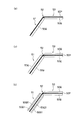
- FIG. 8 is an explanatory diagram for explaining another configuration example of the vibration direction conversion unit 50 and its operation. More specifically, FIG. 5B shows the state of the vibration direction converter 50 with the diaphragm 10 positioned at the reference position, and FIG. 6A shows the state where the diaphragm 10 is displaced toward the acoustic radiation side with respect to the reference position. FIG. 6C shows the state of the vibration direction conversion unit 50 in a state where the vibration plate 10 is displaced in the opposite direction with respect to the acoustic radiation side with respect to the reference position. (The diaphragm 10 is not shown).
- the vibration direction conversion section 50 has a function of converting the angle by receiving a reaction force from the stationary section 100 where the link portion 51 is located on the opposite side to the diaphragm side.
- the vibration direction conversion unit 50 includes a first link portion 51A having one end as a joint portion 52A on the voice coil 30 side and the other end as a joint portion 52B on the diaphragm 10 side, and one end serving as a first link portion.
- 51 has a second link part 51B having a joint part 52C with the intermediate part 51 and a joint part 52D with the stationary part 100 at the other end, and the first link part 51A and the second link part 51B are voiced.
- the coils 30 are inclined in different directions with respect to the vibration direction of the coil 30.
- the vibration direction conversion unit 50 includes a first link portion 51A having one end as a first joint 52A on the voice coil 30 side and the other end as a second joint 52B on the diaphragm 10 side, A second link portion 51B having one end as a third joint portion 52C with the intermediate portion of the first link portion 51A and the other end as a fourth joint portion 52D with the stationary portion 100;
- the joint portion 52A, the second joint portion 52B, and the fourth joint portion 52D are on a circumference having a diameter substantially equal to the length of the first link portion 51A centered on the third joint portion 52C. It is in.
- the joint 52D is the only joint that does not change in position, and is supported by the stationary unit 100 (or the frame 12), and applies a reaction force from the stationary unit 100 to the link portion 51. ing. If a result, the voice coil 30 (or the voice coil support part 40) is moved from the reference position X 0 to X-axis direction by [Delta] X 1, as shown in FIG. 8 (a), the inclined arranged in different directions 1
- the link portion 51A and the second link portion 51B rise substantially at the same angle, and the joint portion 52B receives the reaction force from the stationary portion 100 at the joint portion 52D, and the joint portion 52B reliably moves the diaphragm 10 to the reference position Z 0.
- the length a of the link part from the joint part 52A to the joint part 52C, the length b of the link part from the joint part 52C to the joint part 52B, and the length c of the link part from the joint part 52C to the joint part 52D are substantially equal, and the joint portion 52A and the joint portion 52D are preferably disposed substantially parallel to the moving direction of the voice coil 30.
- the angle formed by the straight line passing through the joint part 52A and the joint part 52D and the straight line passing through the joint part 52B and the joint part 52D is always a right angle.
- the joint portion 52B between the first link portion 51A and the diaphragm 10 always moves along the Z-axis perpendicular to the X-axis.
- 30 vibration directions can be converted to a direction perpendicular to the vibration direction and transmitted to the diaphragm 10.
- FIG. 9 is an explanatory diagram showing a configuration example of the speaker device 1 including the vibration direction conversion unit 50 shown in FIG.
- the stationary part 100 is a part of the frame 12 that supports the diaphragm 10 and the driving part 14.
- the frame 12 has a flat bottom surface 12A, the diaphragm 10 is supported to face the bottom surface 12A of the frame 12, the magnetic gap 20G is formed along the bottom surface 12A of the frame 12, and the vibration direction changing unit 50 is a frame.
- the diaphragm 10 is vibrated in a direction intersecting the bottom surface 12A by a reaction force from the bottom surface 12A.
- FIG. 4A the stationary part 100 is a part of the frame 12 that supports the diaphragm 10 and the driving part 14.
- the frame 12 has a flat bottom surface 12A, the diaphragm 10 is supported to face the bottom surface 12A of the frame 12, the magnetic gap 20G is formed along the bottom surface 12A of the frame 12, and the vibration direction changing unit 50 is a frame.
- the magnetic circuit 20 includes at least a magnet 21 (21A, 21C) and a yoke portion 22 (22A, 22B), and the stationary portion 100 is formed by the yoke portion 22 (22B). Yes.
- the stationary part 100 is formed by the yoke part 22, and by making the yoke part 22 a part of the support member, the speaker device 1 can be further reduced in thickness.
- the vibration direction converter 50 includes the link portion 51 and joint portions 52 (52A, 52B) formed at both ends thereof.
- connection portions 53 (a first connection portion 53A and a second connection portion 53B) are formed on both ends of the link portion 51 via joint portions 52.
- the first connecting portion 53A is a portion that is connected to the voice coil 30 or the voice coil support portion 40 and vibrates integrally with the voice coil 30, and the second connecting portion 53B is connected to the diaphragm 10 to vibrate. It is a portion that vibrates integrally with the plate 10.
- a link portion 51, joint portions 52A and 52B, and first and second connection portions 53A and 53B are integrally formed, and the joint portions 52A and 52B include the joint portions 52A and 52B.
- the continuous member may be a member that forms the entirety of the link portion 51 and the first and second connection portions 53A and 53B, or the link portion 51 and the first and second connection portions 53A and 53B. The member which forms a part of may be sufficient.
- the joint part 52 is formed in a linear shape extending in the width direction as shown in FIG. Further, since the link portion 51 is required to be rigid and the joint portion 52 is required to be refractable, the thickness t2 of the joint portion 52 with respect to the thickness t1 of the link portion 51 or the connecting portion 53. Is formed in a thin shape, so that different properties are given to the integral member.
- the change in thickness between the joint portion 52 and the link portion 51 is formed in an inclined surface shape, and inclined surfaces 51t and 53t whose surfaces face each other at the end portions on both sides of the joint portion 52 are formed.
- a rigid member is integrated with a refractive continuous member to form a link portion 51 or a connecting portion 53, and the joint portion 52 is a portion only of the continuous member.
- a rigid member 50Q is attached to the surface of a continuous member 50P, which is a bendable sheet-like member, to form a link portion 51 or a connecting portion 53.
- the continuous member 50P is continuously extended in the part of the both sides straddling the joint part 52, and the joint part 52 is formed by this continuous member 50P so that bending is possible.
- the link portion 51 or the connecting portion 53 in which the rigid member 50Q is attached to the continuous member 50P is formed in a portion having rigidity.
- the link member 51 or the connecting member 53 is formed by attaching the rigid member 50Q so as to sandwich the continuous member 50P. Again, the portion where the rigid member 50Q is not attached becomes the joint portion 52.
- the rigid member forming the link portion 51 is formed by laminating multilayer rigid members 50Q1 and 50Q2.
- the continuous member 50P preferably has a strength and durability sufficient to withstand the refraction of the joint portion 52 that is repeated when the speaker device is driven, and has a flexibility that does not emit sound when the refraction operation is repeated.
- the continuous member 50P can be formed of a woven or non-woven fabric of high-strength fibers.
- woven fabrics include plain weaves of uniform materials, plain weaves with different warp and weft yarns, plain weaves with alternate yarn materials, plain weaves with twisted yarns, and plain weaves of assortment.
- the high-strength fibers When using high-strength fibers in whole or in part, by arranging the high-strength fibers along the vibration direction of the voice coil 30, sufficient strength against vibration of the voice coil 30 can be obtained.
- warp and weft are both high-strength fibers, both the warp and wefts are evenly tensioned and the durability is improved by tilting the fiber direction by about 45 ° with respect to the vibration direction of the voice coil 30.
- the high-strength fiber an aramid fiber, a carbon fiber, a glass fiber, or the like can be used.
- a dumping agent may be applied (applied).
- the rigid member 50Q is preferably lightweight, easy to mold and rigid after curing, and thermoplastic resin, thermosetting resin, metal, paper, etc. can be used. After the rigid member 50Q is formed into a plate shape, the vibration direction changing portion 50 can be formed by adhering to the surface of the portion of the continuous member 50P excluding the joint portion 52 with an adhesive. When a thermosetting resin is used as the rigid member 50Q, the vibration direction changing portion 50 is formed by partially impregnating the resin in the link portion 51 and the connecting portion 53 of the fibrous continuous member 50P and then curing the resin. can do. When resin or metal is used as the rigid member 50Q, the continuous member 50P and the rigid member 50Q can be integrated in the link portion 51 and the connecting portion 53 by insert molding.
- the holding unit 15 holds the voice coil 30 or the voice coil support unit 40 at a predetermined position in the magnetic gap 20G so that the voice coil 30 does not contact the magnetic circuit 20, and holds the voice coil 30 or the voice coil support unit 40. It is supported so as to vibrate linearly along the vibration direction (X-axis direction).
- the holding unit 15 restricts the voice coil support unit 40 from moving in a direction different from the vibration direction of the voice coil support unit 40, for example, in the Z-axis direction or the Y-axis direction.
- the holding portion 15 can be deformed along the vibration direction of the voice coil 30 and can be formed by a curved plate member having rigidity in a direction crossing the vibration direction.
- FIG. 12 is an explanatory view showing a specific example of a holding mechanism of the voice coil support unit 40 by the holding unit 15.
- the holding portion 15 is formed of, for example, a conductive metal, and is electrically connected to the end of the voice coil 30 or the voice coil lead wire 43 from the end at the end on the voice coil support portion 40 side. Is electrically connected to the audio signal input terminal.
- the holding portion 15 itself may be a vibration wiring made of a conductive metal, or the holding portion 15 may be a wiring board (for example, a linear wiring is formed on the substrate). .
- the voice coil 30 has a substantially rectangular planar shape, and linear portions 30A and 30C formed along the Y-axis direction and linear portions 30B formed along the X-axis direction. , 30D.
- the straight portions 30A and 30C of the voice coil 30 are arranged in the magnetic gap 20G of the magnetic circuit 20, and are defined so that the direction of the magnetic field is along the Z-axis direction.
- the holding portion 15 is a curved plate-like member that allows deformation in one direction along the vibration direction of the voice coil support portion 40 and restricts deformation in the other direction. Is held approximately symmetrically.
- one end of each end of the holding portion 15 is attached to the voice coil support portion 40 side by the connection portion 15X, and the other end is attached to the frame side by the connection portion 15Y.
- the connection portions 15X and 15Y are made of an insulator such as resin, and the voice coil lead wire 43 drawn from the voice coil 30 is electrically connected to the holding portion 15 using solder or the like. 15 is electrically connected to the audio signal input terminal.
- connection portions 15X and 15Y may form an electrical connection terminal, and the connection portion 15X is connected to the end portion of the voice coil 30 or the voice coil lead wire 43 drawn from the end portion.
- the unit 15Y may be electrically connected to the audio signal input terminal.
- a lead wire used in a conventional speaker device vibrates when the speaker device is driven. Therefore, in order to prevent the lead wire from contacting a member constituting the speaker device, such as a frame, in a predetermined space. It is necessary to route the lead wire, which is one factor that hinders the thinning of the speaker device. However, since the voice coil lead wire 43 is formed on the voice coil support portion 40 as in the example of FIG. 12, it is not necessary to provide a predetermined space for routing the voice coil lead wire 43. It is possible to reduce the thickness.
- the other end of the holding portion 15 is attached to the connecting portion 15Y, and the connecting portion 15Y supports the holding portion 15 on the frame so that the voice coil support portion 40 basically vibrates in the X-axis direction. Further, since the voice coil lead wire 43 extends to the conductive holding portion 15 and is electrically connected, the voice coil lead wire 43 and the holding portion 15 can be prevented from being disconnected, and the reliability of the speaker device can be reduced. Can be improved.
- the holding portion 51 made of a conductive metal that is a curved plate-like member allows the movement of the voice coil support portion 6 in the direction along the X axis due to the deformation of the holding portion 15, and the curved plate in the direction along the Z axis.
- the movement is restricted by the high rigidity of the member. Therefore, the voice coil support portion 40 is always maintained at a predetermined height with respect to the frame in the Z-axis direction.
- the holding portion 5 substantially symmetrically, the movement of the voice coil support portion 40 in the Y direction is in a balanced state due to the elastic force of the holding portion 15, which is also held at a predetermined position with respect to the frame. Has been.
- each joint portion 52 in the vibration direction conversion unit 50 described above is formed near the center of the diaphragm 10 with respect to the arrangement of the magnetic circuit 20.
- the plurality of driving units 14 are disposed to face each other along an axis of symmetry when the diaphragm 10 is viewed in plan.
- the plurality of driving units 14 are arranged at substantially equal positions from the center of the diaphragm 10.
- the magnetic circuit 20 is supported on the stationary part 100 (frame 12) near the outer periphery of the diaphragm 10.
- the diaphragm 10 can be vibrated integrally, and the divided vibration of the diaphragm 10 is suppressed, and the reproduction band is expanded. Can expand the bass reproduction limit (lower range). Since the outer peripheral portion of the diaphragm 10 supported by the stationary portion 100 (frame 12) via the edge 11 is a drive support portion, the diaphragm 10 is slightly located near the center during driving. It will vibrate while being bent in a concavo-convex shape, and the direction of sound radiation can be expanded to the surroundings.
- FIGS. 13 to 17 are explanatory views showing speaker devices according to other embodiments of the present invention (FIGS. 13 to 15 and FIG. 16A are plan views in a state where a diaphragm is removed, and FIG. (b), (c), and FIG. 17 are sectional views).
- FIG. (b), (c), and FIG. 17 are sectional views.
- the parts common to the above-described embodiment are given the same reference numerals, and the description given above is used.
- the speaker device 1 (1A to 1F) shown in FIG. 13 to FIG. 15 is a modified example related to the arrangement of the plurality of driving units 14.
- the central axis S of the voice coil 30 in the drive unit 14 is shifted by a predetermined dimension with respect to the symmetry axes L ⁇ b> 1 and L ⁇ b> 2 of the diaphragm 10.
- the illustrated e1, e2, e3, and e4 are the shift amounts. Each shift amount e1, e2, e3, e4 may be the same or different values, and may be zero (no shift).
- the vibration direction of the voice coil 30 is parallel or perpendicular to the symmetry axis L1 or L2.
- the central axis S of the voice coil 30 in the drive unit 14 is shifted by a predetermined angle with respect to the symmetry axes L1 and L2 of the diaphragm 10.
- the illustrated ⁇ 1, ⁇ 2, ⁇ 3, and ⁇ 4 are the shift amounts.
- the shift amounts ⁇ 1, ⁇ 2, ⁇ 3, and ⁇ 4 may be the same or different values, and may be zero (not shifted). Further, in combination with the example shown in FIG.
- the center axis S of the voice coil 30 is shifted by the predetermined dimensions e1, e2, e3, e4 with respect to the symmetry axes L1, L2 of the diaphragm 10, and further The angle may be shifted by e1, e2, e3, e4.
- the drive unit 14 is arranged at a point-symmetrical position with respect to the center O of the diaphragm 10.
- three drive units 14 arranged on the back surface of the diaphragm 10 are provided.
- the number is not limited to this, and may be five, six,.
- one or more of the drive units 14 in the example shown in FIG. 14A are shifted from the point symmetry position by a predetermined dimension or a predetermined angle.
- the example shown in FIG. 15 is an example in which the diaphragm 10 is rectangular.
- the drive unit 14 is disposed oppositely along the symmetry axes L1 and L2 when the diaphragm 10 is viewed in plan, and the example shown in FIG.
- the vibration direction of the voice coil 30 is shifted by a predetermined angle with respect to the example shown in a).
- the center axis S of the voice coil 30 is shifted by the predetermined dimensions e1, e2, e3, e4 with respect to the symmetry axes L1, L2 of the diaphragm 10. May be.
- the vibration direction of the diaphragm 10 is set to a specific direction. It is possible to shift, and the divided vibration of the diaphragm 10 can be suppressed.
- an opening 10P is formed at a substantially central portion of the diaphragm 10.
- the drive unit 14 can be installed on the peripheral side of the diaphragm 10
- a space below the substantially central portion of the diaphragm 10 can be made, and an opening 10 ⁇ / b> P is formed in this space. This can be used as an installation space for various components.
- a high-pitched sound reproduction speaker 200 is provided in the opening 10P.
- the speaker device 1 includes a plurality of driving units 14 having the vibration direction conversion unit 50, so that a thin and high-quality bass reproduction speaker can be obtained.
- the high-pitched sound reproduction speaker 200 substantially at the center of the diaphragm 10, a speaker system having a wide reproduction band can be constructed with high space efficiency.
- an attachment member 201 for attaching the speaker device to the opening 10P is provided.
- the speaker device 1 can be firmly attached to the non-attached portion.
- the attachment member 201 can be used to make a strong attachment.
- Speaker device 1 (1K, 1L) shown in FIG. 17 comprises a plurality of diaphragm 10 to sound emission direction is different (10 1, 10 2), the drive unit 14, the diaphragm 10 (10 1, 10 2 ) A plurality of each is provided.
- the back space of the diaphragm 10 (10 1 , 10 2 ) communicates within the frame 12.
- the high-frequency sound reproduction speaker 200 is provided in the opening 10P formed in each of the diaphragms 10 (10 1 , 10 2 ).
- the speaker device 1 Since the speaker device 1 according to the embodiment of the present invention changes the direction of the vibration of the voice coil 30 by the vibration direction conversion unit 50 and transmits it to the diaphragm 10, the amplitude of the voice coil 30 is increased to increase the vibration of the diaphragm 10. Even if the amplitude is increased, the thickness of the speaker device 1 in the acoustic radiation direction (the total height of the speaker device) does not increase. This makes it possible to obtain a thin speaker device that can emit a large volume of reproduced sound.
- the vibration direction converter 50 reliably transmits the vibration of the voice coil 30 to the diaphragm 10 by a mechanical link mechanism having a relatively simple structure, a speaker device with high reproduction efficiency can be obtained while realizing a reduction in thickness. Therefore, it is possible to emit a high-quality reproduced sound with a relatively simple structure.
- the diaphragm 10 can be vibrated integrally even if the diaphragm 10 is large in area. High-quality reproduced sound can be radiated while suppressing the divided vibration of. In particular, it is effective when low-frequency sound reproduction is performed by increasing the area of the diaphragm 10, and high-quality low-frequency sound reproduction is possible while lowering the speaker device thickness, and the low-frequency sound reproduction limit is further lowered.
- the playback band can be expanded.
- FIG. 18 is an explanatory view showing an electronic apparatus including the speaker device according to the embodiment of the present invention.
- the electronic device 2 such as a mobile phone or a portable information terminal shown in FIG. 1A or the electronic device 3 such as a flat panel display shown in FIG. Since the space can be reduced, the entire electronic device can be made thinner. In addition, sufficient audio output can be obtained even in a thin electronic device.
- FIG. 19 is an explanatory view showing an automobile provided with a speaker according to an embodiment of the present invention.
- the space in the vehicle can be expanded by making the speaker device 1 thinner.
- the speaker device 1 according to the embodiment of the present invention is installed on the door panel, the protrusion of the door panel is eliminated and the operation space of the driver can be expanded. Also, since sufficient audio output can be obtained, music and radio broadcasting can be enjoyed comfortably in the car even during high-speed driving with a lot of noise.
- a hotel inn or training that can accommodate a large number of people, such as a house (building) intended for the residence of people, a meeting, a lecture, a party, etc.
- the speaker device 1 When the speaker device 1 is installed in a facility or the like (building), the thickness space necessary for the installation of the speaker device 1 can be reduced, so that unnecessary space can be deleted and the space can be used effectively.
- projectors and large-screen TVs, etc. there have been examples of providing living rooms with audio / video equipment, while living rooms without audio / video equipment have been provided. In some cases, etc. are used as theater rooms.
- the speaker device 1 Even in such a case, by using the speaker device 1, it is possible to easily convert a living room or the like into a theater room and to effectively use the space in the living room.
- the speaker device 1 may be arranged at, for example, a ceiling or a wall in a living room.
- each of the above-described embodiments can divert each other's technology as long as there is no particular contradiction or problem in its purpose and configuration. Further, the technology in each of the above-described embodiments can be applied to a dynamic speaker device that uses a flat voice coil as necessary (eg, a riffel speaker device, a ribbon speaker device, a sound emitting side of a flat voice coil).
- a dynamic speaker device that uses a flat voice coil as necessary (eg, a riffel speaker device, a ribbon speaker device, a sound emitting side of a flat voice coil).
- the present invention can be applied to a speaker device in which a magnetic pole portion is disposed on the side opposite to the acoustic radiation side, and the speaker device can be thinned.
- PCT / JP2008 / 051197 filed internationally on January 28, 2008 PCT / JP2008 / 68580 filed internationally on October 14, 2008, PCT / JP2009 / 050764 filed internationally on January 20, 2009, All the contents described in PCT / JP2008 / 069480 filed internationally on October 27, 2008 are incorporated in this application.
Landscapes
- Physics & Mathematics (AREA)
- Engineering & Computer Science (AREA)
- Acoustics & Sound (AREA)
- Signal Processing (AREA)
- Audible-Bandwidth Dynamoelectric Transducers Other Than Pickups (AREA)
Abstract
Provided is a thin speaker device capable of high-quality bass reproduction by means of a large-area diaphragm. The speaker device is characterized by being provided with a diaphragm (10), a stationary section (100) for vibratably supporting the outer periphery of the diaphragm (10) along the vibration direction thereof, and plural driving units (14) for supporting the back side of the diaphragm (10) at plural different positions and imparting vibration to the diaphragm (10) in response to an audio signal, and in that the driving unit (14) is provided with a magnetic circuit (20) in which a magnetic gap (20G) is formed along a direction different from the vibration direction of the diaphragm (10), a voice coil (30) vibratably disposed along a uniaxial direction in the magnetic gap (20G), and a rigid vibration direction change section (50) for changing the direction of the vibration of the voice coil (30) and transmitting the vibration changed in direction to the diaphragm (10), the vibration direction change section (50) is equipped with a link portion (51) disposed obliquely with respect to the vibration direction of the voice coil (30) with joints (52) respectively formed on the diaphragm (10) side and the voice coil (30) side, and each of the joints (52) is formed closer to the center of the diaphragm (10) than the location of the magnetic circuit (20).
Description
本発明は、スピーカ装置に関するものである。
The present invention relates to a speaker device.
一般的なスピーカ装置として、ダイナミック型スピーカ装置が知られている(例えば、特許文献1参照)。このダイナミック型スピーカ装置は、例えば図1に示すように、フレーム3Jと、コーン形状の振動板21Jと、振動板21Jをフレーム3Jに支持するエッジ4Jと、振動板21Jの内周部に接合されたボイスコイルボビン610Jと、ボイスコイルボビン610Jをフレーム3Jに支持するダンパ7Jと、ボイスコイルボビン610Jに巻き回されたボイスコイル611Jと、ヨーク51J,磁石52J,プレート53Jを備えると共に、ボイスコイル611Jが配置される磁気ギャップが形成された磁気回路とを有する。このスピーカ装置では、音声信号がボイスコイル611Jに入力されると、磁気ギャップ内のボイスコイル611Jに生じたローレンツ力によりボイスコイルボビン610Jが振動し、その振動によって振動板21Jが駆動される。
As a general speaker device, a dynamic speaker device is known (see, for example, Patent Document 1). As shown in FIG. 1, for example, the dynamic speaker device is joined to a frame 3J, a cone-shaped diaphragm 21J, an edge 4J that supports the diaphragm 21J on the frame 3J, and an inner peripheral portion of the diaphragm 21J. The voice coil bobbin 610J, the damper 7J that supports the voice coil bobbin 610J on the frame 3J, the voice coil 611J wound around the voice coil bobbin 610J, the yoke 51J, the magnet 52J, and the plate 53J, and the voice coil 611J are arranged. And a magnetic circuit in which a magnetic gap is formed. In this speaker device, when a voice signal is input to the voice coil 611J, the voice coil bobbin 610J vibrates due to the Lorentz force generated in the voice coil 611J in the magnetic gap, and the diaphragm 21J is driven by the vibration.
前述した一般的なダイナミック型スピーカ装置は、例えば図1に示すように、振動板21Jの音響放射側に対して反対側にボイスコイル611Jが配設され、ボイスコイル611J及びボイスコイルボビン610Jの振動方向と振動板21Jの振動方向が同じ方向になるように構成されている。そして、このようなスピーカ装置では、振動板21Jが振動するための領域、ボイスコイルボビン610Jが振動するための領域、磁気回路が配置される領域等が振動板21Jの振動方向(音響放射方向)に沿って形成されることになるので、スピーカ装置の全高が比較的大きく成らざるを得ない構造になっている。
For example, as shown in FIG. 1, the general dynamic speaker device described above has a voice coil 611J disposed on the side opposite to the acoustic radiation side of the diaphragm 21J, and vibration directions of the voice coil 611J and the voice coil bobbin 610J. And the vibration direction of the diaphragm 21J is the same. In such a speaker device, the region for vibrating the diaphragm 21J, the region for vibrating the voice coil bobbin 610J, the region where the magnetic circuit is disposed, and the like are in the vibration direction (acoustic radiation direction) of the diaphragm 21J. Therefore, the overall height of the speaker device must be relatively large.
詳細には、図1に示すように、スピーカ装置の振動板21Jの振動方向に沿った大きさは、コーン形状の振動板21Jの振動方向に沿った大きさ及び振動板21Jをフレーム3Jに支持するエッジ4Jの全高(a)、振動板21Jとボイスコイルボビン610Jとの接合部からボイスコイル611Jの上端までのボイスコイルボビン高さ(b)、ボイスコイル高さ(c)、磁気回路の主に磁石高さ(d)、磁気回路の主にヨーク51Jの厚さ(e)等からなる。このようなスピーカ装置においては、充分な振動板21Jの振動ストロークを確保するためには、前述したa,b,c,dの高さを充分に確保する必要があり、また充分な駆動力を得るためには前述したc,d,eの高さを充分に確保する必要があるので、特に、大音量対応型スピーカ装置では、スピーカ装置の全高が大きく成らざるを得ない。
Specifically, as shown in FIG. 1, the size of the diaphragm 21J of the speaker device along the vibration direction is the same as the size of the cone-shaped diaphragm 21J along the vibration direction and the diaphragm 21J is supported by the frame 3J. The height of the edge 4J (a), the voice coil bobbin height (b) from the junction of the diaphragm 21J and the voice coil bobbin 610J to the upper end of the voice coil 611J, the voice coil height (c), and the main magnet of the magnetic circuit It consists of the height (d) and the thickness (e) of the yoke 51J mainly of the magnetic circuit. In such a speaker device, in order to ensure a sufficient vibration stroke of the diaphragm 21J, it is necessary to sufficiently secure the heights a, b, c, d described above, and a sufficient driving force is provided. In order to obtain it, it is necessary to sufficiently secure the heights of c, d, and e described above, and therefore, especially in a loudspeaker type speaker device, the overall height of the speaker device must be large.
このように、従来のスピーカ装置では、ボイスコイルボビン610Jの振動方向と振動板21Jの振動方向とが同方向になっているので、振動板21Jの振幅を大きくして大音量を得ようとすると、ボイスコイルボビン610Jの振動ストロークを確保するためにスピーカ装置の全高が大きくなってしまい、装置の薄型化を達成し難い。すなわち、装置の薄型化と大音量化を両立し難い問題がある。
Thus, in the conventional speaker device, since the vibration direction of the voice coil bobbin 610J and the vibration direction of the diaphragm 21J are the same direction, if the amplitude of the diaphragm 21J is increased to obtain a large volume, In order to ensure the vibration stroke of the voice coil bobbin 610J, the overall height of the speaker device becomes large, and it is difficult to achieve thinning of the device. That is, there is a problem that it is difficult to achieve both a reduction in device thickness and an increase in volume.
しかしながら、ボイスコイル611Jの振動を効率よく振動板21Jに伝達させるためには、ボイスコイル611Jの振動を直接振動板21Jに伝えること、すなわち、ボイスコイル611Jの振動方向と振動板21Jの振動方向とを一致させることが好ましい。ボイスコイル611Jの振動方向と振動板21Jの振動方向が異なる場合には、ボイスコイル611Jの振動が確実に振動板21Jに伝えられないことがあり、これがスピーカ装置の再生効率の悪化に繋がる問題が生じる。特に、高音域の良好な再生特性を得るためには、ボイスコイル611Jの振動を確実に振動板に伝えることが必要になる。
However, in order to efficiently transmit the vibration of the voice coil 611J to the diaphragm 21J, the vibration of the voice coil 611J is directly transmitted to the diaphragm 21J, that is, the vibration direction of the voice coil 611J and the vibration direction of the diaphragm 21J. Are preferably matched. When the vibration direction of the voice coil 611J and the vibration direction of the diaphragm 21J are different, the vibration of the voice coil 611J may not be reliably transmitted to the diaphragm 21J, which causes a problem that the reproduction efficiency of the speaker device is deteriorated. Arise. In particular, in order to obtain good reproduction characteristics in the high sound range, it is necessary to reliably transmit the vibration of the voice coil 611J to the diaphragm.
一方、一般的なダイナミック型スピーカ装置では、コーン形状の振動板21Jの内周部にボイスコイルボビン610Jが接合されており、ボイスコイルボビン610Jから振動板21Jの内周部に駆動力が伝達されるので、振動板全体を略同位相にて駆動させることが比較的困難である。このため振動板全体を略同位相にて駆動することができるスピーカ装置が望まれている。
On the other hand, in a general dynamic type speaker device, the voice coil bobbin 610J is joined to the inner periphery of the cone-shaped diaphragm 21J, and the driving force is transmitted from the voice coil bobbin 610J to the inner periphery of the diaphragm 21J. It is relatively difficult to drive the entire diaphragm at substantially the same phase. Therefore, a speaker device that can drive the entire diaphragm with substantially the same phase is desired.
また、大音量の低音再生を行うには、大口径(大面積)の振動板が必要となる。この際、従来技術のように振動板の中心付近のみにボイスコイルボビン610Jを接続したものでは、ボイスコイル611Jによって発生する駆動力をある程度大きくせざるを得ず、駆動力を大きくするためには磁気回路の大型化が必要になって、スピーカ装置の薄型化を達成できない問題が生じる。更には、大面積の振動板では、振動板形状をコーン状にすることで振動板の剛性を高めることが可能ではあるものの、単一のボイスコイルボビン611Jによる駆動では、分割振動が生じやすくなり、広帯域にわたって高品位な再生音が得られない。また低音再生限界を低くできない問題がある。
Also, a large-diameter (large-area) diaphragm is required to perform low-volume sound reproduction. At this time, in the case where the voice coil bobbin 610J is connected only near the center of the diaphragm as in the prior art, the driving force generated by the voice coil 611J must be increased to some extent, and in order to increase the driving force, the magnetic force As the circuit size needs to be increased, there is a problem that the speaker device cannot be thinned. Furthermore, in a large-area diaphragm, although it is possible to increase the rigidity of the diaphragm by making the diaphragm shape into a cone shape, when driven by a single voice coil bobbin 611J, split vibration tends to occur, High-quality playback sound cannot be obtained over a wide band. There is also a problem that the bass reproduction limit cannot be lowered.
ところで、薄型スピーカ装置として、例えばコンデンサ型スピーカ装置が知られている。このコンデンサ型スピーカ装置は、振動板(可動電極)と固定電極とが向い合せに配置された構造を有する。このスピーカ装置は、電極間への直流電圧の印加により振動板が変位した状態となり、音声信号が重畳された信号が電極に入力されると、その信号に応じて振動板が振動する。しかし、このコンデンサ型スピーカ装置では、比較的大振幅の音声信号が入力されると、駆動力が非線形に著しく変化して、再生音の音質が比較的低くなる場合がある。
Incidentally, for example, a capacitor type speaker device is known as a thin speaker device. This capacitor type speaker device has a structure in which a diaphragm (movable electrode) and a fixed electrode are arranged facing each other. In this speaker device, the diaphragm is displaced by applying a DC voltage between the electrodes, and when a signal on which an audio signal is superimposed is input to the electrodes, the diaphragm vibrates according to the signal. However, in this capacitor-type speaker device, when a relatively large amplitude audio signal is input, the driving force may change significantly in a non-linear manner, and the sound quality of the reproduced sound may be relatively low.
本発明は、このような問題に対処することを課題の一例とするものである。すなわち、比較的簡単な構造で大音量の再生音を放射することができる薄型のスピーカ装置を提供すること、ボイスコイルの振動を確実に振動板に伝えて再生効率の高いスピーカ装置を得ること、比較的簡単な構造で高音質な再生音を放射することができる薄型のスピーカ装置を提供すること、また、比較的簡単な構成で振動板が略同位相で振動する薄型のスピーカ装置を提供すること、大面積の振動板で高品位且つ大音量の低音再生を可能にしながら、薄型のスピーカ装置を提供できること、等が本発明の目的である。
The present invention is an example of a problem to deal with such a problem. That is, to provide a thin speaker device that can radiate a large volume of reproduced sound with a relatively simple structure, to reliably transmit the vibration of the voice coil to the diaphragm, and to obtain a speaker device with high reproduction efficiency, Provided is a thin speaker device capable of emitting high-quality reproduced sound with a relatively simple structure, and also provides a thin speaker device in which a diaphragm vibrates in substantially the same phase with a relatively simple configuration. In addition, an object of the present invention is to provide a thin speaker device while enabling high-quality and high-volume sound reproduction with a large-area diaphragm.
このような目的を達成するために、本発明によるスピーカ装置は、以下の独立請求項に係る構成を少なくとも具備するものである。
[請求項1]振動板と、該振動板の外周を振動方向に沿って振動自在に支持する静止部と、該振動板の背面を複数の異なる箇所で支持し、音声信号によって前記振動板に振動を与える複数の駆動部とを備え、前記駆動部は、前記振動板の振動方向とは異なる方向に沿って磁気ギャップを形成する磁気回路と、前記磁気ギャップ内に一軸方向に沿って振動自在に配置されたボイスコイルと、前記ボイスコイルの振動を方向変換して前記振動板に伝える剛性の振動方向変換部とを備え、前記振動方向変換部は、前記振動板側と前記ボイスコイル側のそれぞれに関節部を形成して前記ボイスコイルの振動方向に対して斜設されたリンク部分を有し、前記各関節部が前記磁気回路の配置に対して前記振動板の中心寄りに形成されることを特徴とするスピーカ装置。 In order to achieve such an object, the speaker device according to the present invention includes at least the configuration according to the following independent claims.
[Claim 1] A diaphragm, a stationary part that supports the outer periphery of the diaphragm so as to freely vibrate along a vibration direction, and a back surface of the diaphragm are supported at a plurality of different locations, and an audio signal is applied to the diaphragm. A plurality of drive units for applying vibration, wherein the drive unit is capable of vibrating along a uniaxial direction in the magnetic gap and a magnetic circuit that forms a magnetic gap along a direction different from the vibration direction of the diaphragm. And a rigid vibration direction conversion unit that changes the direction of vibration of the voice coil and transmits the vibration to the diaphragm, and the vibration direction conversion unit is provided on the diaphragm side and the voice coil side. Each of the joint portions is formed obliquely with respect to the vibration direction of the voice coil, and each joint portion is formed near the center of the diaphragm with respect to the arrangement of the magnetic circuit. It is characterized by that Over mosquito devices.
以下、図面を参照しながら本発明の実施形態を説明する。本発明の実施形態は図示の内容を含むがこれのみに限定されるものではない。なお、以後の各図の説明で、既に説明した部位と共通する部分は同一符号を付して重複説明を一部省略する。
Hereinafter, embodiments of the present invention will be described with reference to the drawings. The embodiment of the present invention includes the contents shown in the drawings, but is not limited thereto. In the following description of each drawing, parts that are common to the parts that have already been described are assigned the same reference numerals, and duplicate descriptions are partially omitted.
[スピーカ装置の全体構成;図2]
図2は、本発明の実施形態に係るスピーカ装置の全体構成を示した説明図である(同図(a)がA-A断面図、同図(b)が振動板を除いた状態の平面図)。スピーカ装置1は、振動板10と、振動板10の外周を振動方向に沿って振動自在に支持する静止部100と、振動板10の背面を複数の異なる箇所で支持し、音声信号によって振動板10に振動を与える複数の駆動部14とを備え、駆動部14は、振動板10の振動方向とは異なる方向に沿って磁気ギャップ20Gを形成する磁気回路20と、磁気ギャップ20G内に一軸方向に沿って振動自在に配置されたボイスコイル30と、ボイスコイル30の振動を方向変換して振動板10に伝える剛性の振動方向変換部50とを備え、振動方向変換部50は、振動板10側とボイスコイル30側のそれぞれに関節部52を形成してボイスコイル30の振動方向に対して斜設されたリンク部分51を有し、各関節部52が磁気回路20の配置に対して振動板10の中心寄りに形成されている。 [Overall configuration of speaker device; FIG. 2]
2A and 2B are explanatory views showing the overall configuration of the speaker device according to the embodiment of the present invention (FIG. 2A is a cross-sectional view taken along the line AA, and FIG. 2B is a plan view in a state where a diaphragm is removed. Figure). Thespeaker device 1 supports a diaphragm 10, a stationary part 100 that supports the outer periphery of the diaphragm 10 so as to freely vibrate along a vibration direction, and supports the back surface of the diaphragm 10 at a plurality of different locations, and generates a diaphragm by means of an audio signal. And a plurality of driving units 14 that apply vibration to the magnetic circuit 20. The driving unit 14 includes a magnetic circuit 20 that forms a magnetic gap 20 </ b> G along a direction different from the vibration direction of the diaphragm 10, and a uniaxial direction within the magnetic gap 20 </ b> G. The voice coil 30 is arranged so as to freely vibrate along a vibration direction, and a rigid vibration direction conversion unit 50 that changes the direction of the vibration of the voice coil 30 and transmits the vibration to the vibration plate 10. The joint portion 52 is formed on each of the side of the voice coil 30 and the link portion 51 is obliquely arranged with respect to the vibration direction of the voice coil 30. It is formed near the center of the diaphragm 10.
図2は、本発明の実施形態に係るスピーカ装置の全体構成を示した説明図である(同図(a)がA-A断面図、同図(b)が振動板を除いた状態の平面図)。スピーカ装置1は、振動板10と、振動板10の外周を振動方向に沿って振動自在に支持する静止部100と、振動板10の背面を複数の異なる箇所で支持し、音声信号によって振動板10に振動を与える複数の駆動部14とを備え、駆動部14は、振動板10の振動方向とは異なる方向に沿って磁気ギャップ20Gを形成する磁気回路20と、磁気ギャップ20G内に一軸方向に沿って振動自在に配置されたボイスコイル30と、ボイスコイル30の振動を方向変換して振動板10に伝える剛性の振動方向変換部50とを備え、振動方向変換部50は、振動板10側とボイスコイル30側のそれぞれに関節部52を形成してボイスコイル30の振動方向に対して斜設されたリンク部分51を有し、各関節部52が磁気回路20の配置に対して振動板10の中心寄りに形成されている。 [Overall configuration of speaker device; FIG. 2]
2A and 2B are explanatory views showing the overall configuration of the speaker device according to the embodiment of the present invention (FIG. 2A is a cross-sectional view taken along the line AA, and FIG. 2B is a plan view in a state where a diaphragm is removed. Figure). The
振動板10は、図2に示した例では、平面視が円形状であるが、楕円形や、後述するような平面視矩形状やその他の形状のものであってもよい。また、図示の例は、振動板10の断面形状が平面である。
In the example shown in FIG. 2, the diaphragm 10 has a circular shape in plan view, but may have an elliptical shape, a rectangular shape in plan view as described later, or other shapes. In the illustrated example, the cross-sectional shape of the diaphragm 10 is a plane.
静止部100は、振動板10及び駆動部14等の振動を支持する部位の総称であって、ここでは、フレーム12及びフレーム12に一体に形成されるか或いはフレーム12に取り付けられる取り付け部12Cが静止部100にあたる。静止部100は、それ自体が完全に静止していることを意図するわけではなく、それ全体が駆動部14の振動の影響を受けて、或いは他の力を受けて、振動するものであってもよい。振動板10の外周部はエッジ11を介して静止部100であるフレーム12に支持されている。
The stationary part 100 is a general term for parts that support vibrations such as the diaphragm 10 and the drive part 14. Here, the stationary part 100 is formed integrally with the frame 12 and the frame 12, or an attachment part 12 </ b> C attached to the frame 12. It corresponds to the stationary part 100. The stationary part 100 is not intended to be completely stationary per se, but is entirely oscillated under the influence of the vibration of the driving part 14 or other force. Also good. The outer peripheral portion of the diaphragm 10 is supported by a frame 12 that is a stationary portion 100 via an edge 11.
駆動部14は、磁気回路20、ボイスコイル30、振動方向変換部50を備えており、ボイスコイル30が磁気回路20の磁気ギャップ20Gに沿って一軸方向に振動し、その振動を振動方向変換部50が方向変換して振動板10に伝える。図示の例では、X軸方向に沿ってボイスコイル30が振動し、それと直交するZ軸方向に振動板10が振動可能に配置されており、振動方向変換部50は、ボイスコイル30のX軸方向の振動を自身の斜設角度の変化に変換して、振動板10をZ軸方向に振動させている。
The drive unit 14 includes a magnetic circuit 20, a voice coil 30, and a vibration direction conversion unit 50. The voice coil 30 vibrates in a uniaxial direction along the magnetic gap 20G of the magnetic circuit 20, and the vibration is converted into a vibration direction conversion unit. 50 changes its direction and transmits it to the diaphragm 10. In the illustrated example, the voice coil 30 vibrates along the X-axis direction, and the diaphragm 10 is arranged so as to vibrate in the Z-axis direction perpendicular to the X-axis direction. The vibration in the direction is converted into a change in its oblique angle, and the diaphragm 10 is vibrated in the Z-axis direction.
ボイスコイル30は、音声信号が入力される導線を巻き回して形成され、それ自身が静止部100に振動自在に配置されるか、或いはボイスコイル支持部40を介して静止部100に振動自在に配置される。ボイスコイル支持部40は、例えば平板状の絶縁部材で形成することができ、その表面上又は内部にボイスコイル30が支持される。
The voice coil 30 is formed by winding a conducting wire to which an audio signal is input, and is itself oscillated on the stationary part 100 or can be oscillated on the stationary part 100 via the voice coil support part 40. Be placed. The voice coil support portion 40 can be formed of, for example, a flat insulating member, and the voice coil 30 is supported on the surface or inside thereof.
このボイスコイル30は、保持部15によって静止部100となる取り付け部12Cに保持されている。保持部15は、ボイスコイル30又はボイスコイル支持部40を振動方向(例えばX軸方向)に沿って振動自在に静止部100に保持すると共に、それ以外の方向へは移動しないように規制する構成を有する。例えば、保持部15は、ボイスコイル30の振動方向(例えば、X軸方向)に沿って変形可能であり、この振動方向に交差する方向には剛性を有する湾曲板部材によって形成することができる。
The voice coil 30 is held by the holding portion 15 on the attachment portion 12C that becomes the stationary portion 100. The holding unit 15 is configured to hold the voice coil 30 or the voice coil support unit 40 on the stationary unit 100 so as to be able to vibrate along the vibration direction (for example, the X-axis direction) and to prevent the voice coil 30 or the voice coil support unit 40 from moving in other directions. Have For example, the holding portion 15 can be deformed along the vibration direction (for example, the X-axis direction) of the voice coil 30, and can be formed by a curved plate member having rigidity in a direction crossing the vibration direction.
このようなスピーカ装置1は、複数の駆動部14のボイスコイル30に同じ音声信号を入力することで、各ボイスコイル30は同一平面方向(例えば図示X軸方向又はY軸方向)に沿って振動する。これによって各駆動部14の振動方向変換部50を介して振動板10がボイスコイル30の振動方向とは異なる方向(例えば図示Z軸方向)に振動する。その振動方向が音響放射方向SDである。
In such a speaker device 1, the same voice signal is input to the voice coils 30 of the plurality of drive units 14, so that each voice coil 30 vibrates along the same plane direction (for example, the X-axis direction or the Y-axis direction in the drawing). To do. As a result, the diaphragm 10 vibrates in a direction different from the vibration direction of the voice coil 30 (for example, the Z-axis direction in the drawing) via the vibration direction conversion unit 50 of each drive unit 14. The vibration direction is the acoustic radiation direction SD.
このようなスピーカ装置1によると、振動板10の背面を複数の異なる箇所で支持し、音声信号によって振動を与える駆動部14が複数設けられるので、比較的大きな面積の振動板10であっても、振動板10を一体的に振動させることが可能になる。これによって振動板10の分割振動の発生を抑制して、高音質の再生を実現することが可能になる。また、振動板10の面積を大きくして、低音再生時の高音圧を小さな振幅で得ることが可能になり、高品位の低音再生が可能になる。
According to such a speaker device 1, since the plurality of drive units 14 that support the back surface of the diaphragm 10 at a plurality of different locations and apply vibrations by audio signals are provided, even the diaphragm 10 having a relatively large area is provided. The diaphragm 10 can be vibrated integrally. As a result, it is possible to suppress the generation of the divided vibration of the diaphragm 10 and realize high-quality reproduction. In addition, by increasing the area of the diaphragm 10, it is possible to obtain a high sound pressure during low sound reproduction with a small amplitude, and high-quality low sound reproduction becomes possible.
また、振動方向変換部50によって、ボイスコイル30の振動方向と振動板10の振動方向を異なる方向にしているので、振動板10の振動方向に沿ってボイスコイル30を振動させる場合と比較して、振動板10の背面側を薄型化することが可能になる。これによって、低音域を高音圧で再生できる薄型のスピーカ装置を得ることができる。
In addition, since the vibration direction of the voice coil 30 and the vibration direction of the diaphragm 10 are made different from each other by the vibration direction conversion unit 50, compared with the case where the voice coil 30 is vibrated along the vibration direction of the diaphragm 10. The back side of the diaphragm 10 can be reduced in thickness. As a result, a thin speaker device capable of reproducing the low sound range with high sound pressure can be obtained.
また、ボイスコイル30の振動を振動方向変換部50によって方向変換して振動板10に伝えるので、ボイスコイル30の振幅を大きくすることで、振動板10の振幅を大きくしても、スピーカ装置1の音響放射方向の厚さ(スピーカ装置の全高)は厚くならない。これによって、大音量の再生音を放射することができる薄型のスピーカ装置を得ることができる。
Further, since the vibration of the voice coil 30 is redirected by the vibration direction converter 50 and transmitted to the diaphragm 10, the speaker device 1 can be increased even if the amplitude of the diaphragm 10 is increased by increasing the amplitude of the voice coil 30. The thickness in the acoustic radiation direction (the overall height of the speaker device) does not increase. This makes it possible to obtain a thin speaker device that can emit a large volume of reproduced sound.
[磁気回路/ボイスコイル;図3~図6]
図3~図6は、磁気回路及びボイスコイルを説明する説明図である。 [Magnetic circuit / voice coil; FIGS. 3 to 6]
3 to 6 are explanatory views for explaining the magnetic circuit and the voice coil.
図3~図6は、磁気回路及びボイスコイルを説明する説明図である。 [Magnetic circuit / voice coil; FIGS. 3 to 6]
3 to 6 are explanatory views for explaining the magnetic circuit and the voice coil.
ボイスコイル30を振動させるための磁気回路20は、ボイスコイル30の振動方向に沿った磁気ギャップ20Gを形成しているだけでなく、ボイスコイル30に電流(音声振動に伴う音声電流)を流すことで、ボイスコイル30にローレンツ力を作用させるために、磁気ギャップ20Gが逆向きで一対の磁場を形成している。これによって、ボイスコイル30に音声電流が流れると、ボイスコイル30は一対の磁場が形成された磁気ギャップ20Gの配置方向に沿って振動することができる。
The magnetic circuit 20 for vibrating the voice coil 30 not only forms a magnetic gap 20G along the vibration direction of the voice coil 30, but also causes a current (voice current accompanying voice vibration) to flow through the voice coil 30. Thus, in order to apply the Lorentz force to the voice coil 30, the magnetic gap 20G forms a pair of magnetic fields in opposite directions. Thus, when an audio current flows through the voice coil 30, the voice coil 30 can vibrate along the arrangement direction of the magnetic gap 20G in which a pair of magnetic fields are formed.
磁気回路20は、磁石21とヨーク部22によって形成されており、Z軸方向で互いに逆向きの磁場を形成する一対の磁気ギャップ20GをX軸方向に所定間隔で並べて形成し、各磁気ギャップ20Gを流れる電流がY軸方向で互いに逆方向になるようにボイスコイル30を巻き回すことで、ボイスコイル30にX軸方向に沿ったローレンツ力が働くようにしている。磁石21とヨーク部22の配置はいくつかの異なる形態にして前述と同様な機能を有する磁気回路20を形成することができる。
The magnetic circuit 20 is formed by a magnet 21 and a yoke portion 22, and is formed by arranging a pair of magnetic gaps 20G that form magnetic fields opposite to each other in the Z-axis direction at predetermined intervals in the X-axis direction. The voice coil 30 is wound so that the currents flowing in the Y-axis direction are opposite to each other in the Y-axis direction, so that the Lorentz force along the X-axis direction acts on the voice coil 30. The magnetic circuit 20 having the same function as described above can be formed by arranging the magnet 21 and the yoke portion 22 in several different forms.
図3及び図4に示した例では、磁気回路20は、複数の磁石21(21A~21D)を有する。この磁気回路20では、磁石21が、磁気ギャップ20Gの磁場の方向に沿った両側に設けられている。図示の例では、ヨーク部22は、下側のヨーク部22A、上側のヨーク部22B、および支柱部22Cを有する。ヨーク部22A,22Bは規定間隔をあけて略平行に配置されており、中央部には、支柱部22Cがヨーク部22A,22Bに対して略直交する方向へ延在するように形成されている。
In the example shown in FIGS. 3 and 4, the magnetic circuit 20 includes a plurality of magnets 21 (21A to 21D). In the magnetic circuit 20, the magnets 21 are provided on both sides along the direction of the magnetic field of the magnetic gap 20G. In the illustrated example, the yoke portion 22 includes a lower yoke portion 22A, an upper yoke portion 22B, and a column portion 22C. The yoke portions 22A and 22B are disposed substantially parallel to each other with a specified interval, and the column portion 22C is formed at the center portion so as to extend in a direction substantially orthogonal to the yoke portions 22A and 22B. .
ヨーク部22A,22Bには磁石21A~21Dが配置され、磁石21Aと磁石21Cとで一つの磁気ギャップ20G2が形成され、磁石21Bと磁石21Dとでもう一つの磁気ギャップ20G1が形成されている。この一対の磁気ギャップ20G1と磁気ギャップ20G2は、平面的に並べて形成され、互いに逆方向の磁場が形成されるようになっている。
Magnets 21A to 21D are arranged in the yoke portions 22A and 22B, and one magnetic gap 20G2 is formed by the magnet 21A and the magnet 21C, and another magnetic gap 20G1 is formed by the magnet 21B and the magnet 21D. The pair of magnetic gaps 20G1 and 20G2 are formed side by side in a plane, and magnetic fields in opposite directions are formed.
一方、ボイスコイル30は、平面形状が略矩形状に形成されており、Y軸方向に沿って形成された直線部30A,30Cと、X軸方向に沿って形成された直線部30B,30Dにより構成されている。ボイスコイル30の直線部30A,30Cは、磁気回路20の各磁気ギャップ20G内に配置され、磁場の方向がZ軸方向に沿うように規定されている。ボイスコイル30の直線部30B,30Dには磁場を印加しないほうが好ましい。また、直線部30B,30Dに磁場が印加されている場合でも、その直線部30B,30Dに生じるローレンツ力が互いに相殺するように構成されている。ボイスコイル30は、巻き数を比較的多くすることで、磁気ギャップ20G内に配置されるボイスコイル30の一部分を比較的大きくすることができ、スピーカ駆動時、比較的大きな駆動力を得ることができる。
On the other hand, the voice coil 30 is formed in a substantially rectangular planar shape, and includes linear portions 30A and 30C formed along the Y-axis direction and linear portions 30B and 30D formed along the X-axis direction. It is configured. The straight portions 30A and 30C of the voice coil 30 are arranged in each magnetic gap 20G of the magnetic circuit 20, and the direction of the magnetic field is defined so as to be along the Z-axis direction. It is preferable not to apply a magnetic field to the straight portions 30B and 30D of the voice coil 30. Further, even when a magnetic field is applied to the straight portions 30B and 30D, the Lorentz forces generated in the straight portions 30B and 30D are configured to cancel each other. By making the number of turns of the voice coil 30 relatively large, a part of the voice coil 30 disposed in the magnetic gap 20G can be made relatively large, and a relatively large driving force can be obtained when the speaker is driven. it can.
なお、図示の例では、ボイスコイル30を絶縁平面板41からなるボイスコイル支持部40で支持している例を示しており、この絶縁平面板41に開孔部41bを形成した例を示しているが、ボイスコイル30に剛性を付与して全体を板状に形成することもできる。ボイスコイル30が剛性を有する場合にはボイスコイル支持部40を用いなくても構わない。
In the illustrated example, an example is shown in which the voice coil 30 is supported by a voice coil support portion 40 made of an insulating flat plate 41, and an example in which an opening 41b is formed in the insulating flat plate 41 is shown. However, it is also possible to give the voice coil 30 rigidity and form the whole in a plate shape. When the voice coil 30 has rigidity, the voice coil support part 40 may not be used.
磁気回路20は、図4に示す例では、ボイスコイル30の直線部30Aにかかる磁場の向きが、直線部30Cに係る磁場の向きに対して逆向きとなるように、複数の磁石21A~21Dに対して、磁石21Aと磁石21Cが同方向に着磁され、磁石21Bと磁石21Dがそれとは逆の同方向に着磁されている。磁石21の着磁は磁石21とヨーク部22とを組み付けた後に行うことができるが、図3,図4に示した例ではその際の着磁工程を2回行うことが必要になる。
In the example shown in FIG. 4, the magnetic circuit 20 includes a plurality of magnets 21A to 21D such that the direction of the magnetic field applied to the straight part 30A of the voice coil 30 is opposite to the direction of the magnetic field related to the straight part 30C. On the other hand, the magnet 21A and the magnet 21C are magnetized in the same direction, and the magnet 21B and the magnet 21D are magnetized in the opposite direction. Magnetization of the magnet 21 can be performed after the magnet 21 and the yoke portion 22 are assembled, but in the example shown in FIGS. 3 and 4, it is necessary to perform the magnetizing process at that time twice.
これに対して、図5及び図6に示す例では、磁気ギャップ20G2を同方向に着磁された磁石21A,21Cによって形成し、磁気ギャップ20G1はヨーク部22A,22Bのそれぞれに形成したヨーク凸部22a,22b間に形成している。これによると、磁石21とヨーク部22とを組み付けた後に行う着磁工程を1回で済ませることができ、工程の簡略化が可能になる。
On the other hand, in the example shown in FIGS. 5 and 6, the magnetic gap 20G2 is formed by magnets 21A and 21C magnetized in the same direction, and the magnetic gap 20G1 is a yoke protrusion formed on each of the yoke portions 22A and 22B. It is formed between the portions 22a and 22b. According to this, the magnetizing process performed after assembling the magnet 21 and the yoke part 22 can be completed once, and the process can be simplified.
また、図示の例では、ヨーク部22を取り付け部12C等の静止部に位置決めするための位置決め支持部22A1,22B1が、ヨーク部22自身に形成されている。これによると、前述した支柱部22Cを省くことができ、取り付け部12C等の静止部に対するヨーク部22の位置決めによって磁気ギャップ20Gの間隔が規定される。
[振動方向変換部;図7~図11]
図7及び図8は、振動方向変換部50の構成例と動作を説明する説明図である。ボイスコイル30の振動を方向変換して振動板10に伝える剛性の振動方向変換部50は、振動板10側とボイスコイル30側のそれぞれに関節部52を形成してボイスコイル30の振動方向に対して斜設されたリンク部分51を有する。ここで、関節部52とは、2つの剛性を有する部材を回転自在に接合する部分、又は一体化された剛性を有する2つの部分を屈折又は屈曲自在にする部分であり、リンク部分51とは、関節部52が端部に形成された剛性を有する部分である。ここで、剛性とは容易に変形しないことを指し、全く変形しないことのみを指しているわけではない。リンク部分51は、板状又は棒状に形成することができる。 In the illustrated example, positioning support portions 22A 1 and 22B 1 for positioning the yoke portion 22 on a stationary portion such as the attachment portion 12C are formed on the yoke portion 22 itself. According to this, the post portion 22C described above can be omitted, and the interval of the magnetic gap 20G is defined by the positioning of the yoke portion 22 with respect to the stationary portion such as the attachment portion 12C.
[Vibration direction conversion unit; FIGS. 7 to 11]
7 and 8 are explanatory diagrams for explaining a configuration example and operation of thevibration direction converter 50. The rigid vibration direction conversion unit 50 that changes the direction of the vibration of the voice coil 30 and transmits the vibration to the diaphragm 10 is formed with joints 52 on the diaphragm 10 side and the voice coil 30 side, respectively. It has the link part 51 inclined with respect to it. Here, the joint part 52 is a part that rotatably joins two rigid members, or a part that refracts or bends two integrated rigid parts. The joint portion 52 is a rigid portion formed at the end. Here, the rigidity means that it does not easily deform, and does not mean that it does not deform at all. The link portion 51 can be formed in a plate shape or a rod shape.
[振動方向変換部;図7~図11]
図7及び図8は、振動方向変換部50の構成例と動作を説明する説明図である。ボイスコイル30の振動を方向変換して振動板10に伝える剛性の振動方向変換部50は、振動板10側とボイスコイル30側のそれぞれに関節部52を形成してボイスコイル30の振動方向に対して斜設されたリンク部分51を有する。ここで、関節部52とは、2つの剛性を有する部材を回転自在に接合する部分、又は一体化された剛性を有する2つの部分を屈折又は屈曲自在にする部分であり、リンク部分51とは、関節部52が端部に形成された剛性を有する部分である。ここで、剛性とは容易に変形しないことを指し、全く変形しないことのみを指しているわけではない。リンク部分51は、板状又は棒状に形成することができる。 In the illustrated example,
[Vibration direction conversion unit; FIGS. 7 to 11]
7 and 8 are explanatory diagrams for explaining a configuration example and operation of the
図7に示した実施形態では、一つのリンク部分51を備え、その両端に関節部52(52A,52B)が形成され、一方の関節部52Aがボイスコイル30又はボイスコイル支持部40の端部に形成され、他方の関節部52Bが振動板10側に形成されている。関節部52Bは、振動板10に接続されていてもよいし、振動板10に他の部材を介して接続されていてもよい。
In the embodiment shown in FIG. 7, one link portion 51 is provided, joint portions 52 (52A, 52B) are formed at both ends thereof, and one joint portion 52A is an end portion of the voice coil 30 or the voice coil support portion 40. The other joint 52B is formed on the diaphragm 10 side. The joint part 52B may be connected to the diaphragm 10 or may be connected to the diaphragm 10 via another member.
図7(a)は、リンク部分51が振動の中間位置にある場合を示している。リンク部分51は、ボイスコイル30(又はボイスコイル支持部40)と振動板10との間に角度θ0で斜設されている。このとき、ボイスコイル30から振動板10の振動方向に沿って距離H0だけ離れた位置Z0に振動板10側の関節部52Bが配置されている。ボイスコイル30(又はボイスコイル支持部40)は、一軸方向(例えば、X軸方向)に振動するように振動方向が規制されており、振動板10はボイスコイル30の振動方向とは異なる方向(例えばZ軸方向)に振動するように振動方向が規制されている。
FIG. 7A shows a case where the link portion 51 is at an intermediate position of vibration. The link portion 51 is obliquely provided at an angle θ 0 between the voice coil 30 (or the voice coil support portion 40) and the diaphragm 10. At this time, the joint portion 52B on the diaphragm 10 side is disposed at a position Z 0 away from the voice coil 30 along the vibration direction of the diaphragm 10 by a distance H 0 . The vibration direction of the voice coil 30 (or the voice coil support portion 40) is regulated so as to vibrate in one axial direction (for example, the X-axis direction), and the diaphragm 10 has a direction different from the vibration direction of the voice coil 30 ( For example, the vibration direction is regulated so as to vibrate in the Z-axis direction).
同図(b)に示すように、ボイスコイル30の端部に形成された関節部52Aが当初の位置X0から振動方向(X軸方向)にΔX1だけ移動して位置X1に達すると、リンク部分51の傾斜角度がθ1(θ0>θ1)に変換されて、振動板10側の関節部52Bの位置が振動板10の振動方向(Z軸方向)にΔZ1だけ移動して位置Z1に達することになる。すなわち、振動板10をΔZ1だけ振動方向に沿って押し上げることになる。
As shown in FIG. (B), when moved to the formed at the end portion of the voice coil 30 joint portion 52A is the vibration direction from the initial position X 0 (X axis direction) by [Delta] X 1 reaches the position X 1 The inclination angle of the link portion 51 is converted to θ 1 (θ 0 > θ 1 ), and the position of the joint portion 52B on the diaphragm 10 side is moved by ΔZ 1 in the vibration direction (Z-axis direction) of the diaphragm 10. Thus, the position Z 1 is reached. That is, the diaphragm 10 is pushed up along the vibration direction by ΔZ 1 .
同図(c)に示すように、ボイスコイル30の端部に形成された関節部52Aが当初の位置X0から振動方向(-X軸方向)にΔX2だけ移動して位置X2に達すると、リンク部分51の傾斜角度がθ2(θ0<θ2)に変換されて、振動板10側の関節部52Bの位置が振動板10の振動方向(-Z軸方向)にΔZ2だけ移動して位置Z2に達することになる。すなわち、振動板10をΔZ2だけ振動方向に沿って押し下げることになる。
As shown in FIG. (C), the position X 2 to move is formed on the end portion of the voice coil 30 joint portion 52A from the initial position X 0 to the vibration direction (-X axis direction) by [Delta] X 2 reaches Then, the inclination angle of the link portion 51 is converted to θ 2 (θ 0 <θ 2 ), and the position of the joint portion 52B on the diaphragm 10 side is ΔZ 2 in the vibration direction (−Z axis direction) of the diaphragm 10. move and will reach the position Z 2. That is, the diaphragm 10 is pushed down along the vibration direction by ΔZ 2 .
このようにリンク部分51及び関節部52(52A,52B)からなる振動方向変換部50の機能は、ボイスコイル30の振動をリンク部分51の角度変化に変換して振動板10に伝え、振動板10をボイスコイル30の振動方向とは異なる方向に振動させることである。
As described above, the function of the vibration direction conversion unit 50 including the link portion 51 and the joint portion 52 (52A, 52B) converts the vibration of the voice coil 30 into an angle change of the link portion 51 and transmits the change to the vibration plate 10, thereby transmitting the vibration plate. 10 is caused to vibrate in a direction different from the vibration direction of the voice coil 30.
図8は、振動方向変換部50の他の構成例及びその動作を説明するための説明図である。詳細には、同図(b)は振動板10が基準位置に位置した状態の振動方向変換部50の状態、同図(a)は振動板10が基準位置に対して音響放射側に変位している状態の振動方向変換部50の状態、同図(c)は振動板10が基準位置に対して音響放射側に対して反対方向に変位している状態の振動方向変換部50の状態を示している(振動板10は図示省略している)。
FIG. 8 is an explanatory diagram for explaining another configuration example of the vibration direction conversion unit 50 and its operation. More specifically, FIG. 5B shows the state of the vibration direction converter 50 with the diaphragm 10 positioned at the reference position, and FIG. 6A shows the state where the diaphragm 10 is displaced toward the acoustic radiation side with respect to the reference position. FIG. 6C shows the state of the vibration direction conversion unit 50 in a state where the vibration plate 10 is displaced in the opposite direction with respect to the acoustic radiation side with respect to the reference position. (The diaphragm 10 is not shown).
この振動方向変換部50は、リンク部分51が振動板側とは逆側に位置する静止部100からの反力を受けて角度変換する機能を有する。詳しくは、振動方向変換部50は、一端をボイスコイル30側の関節部52Aとし、他端を振動板10側の関節部52Bとする第1のリンク部分51Aと、一端を第1のリンク部分51の中間部との関節部52Cとし、他端を静止部100との関節部52Dとする第2のリンク部分51Bとを有し、第1のリンク部分51Aと第2のリンク部分51Bをボイスコイル30の振動方向に対して異なる方向に傾斜配置している。更に詳しくは、振動方向変換部50は、一端をボイスコイル30側の第1の関節部52Aとし、他端を振動板10側の第2の関節部52Bとする第1のリンク部分51Aと、一端を第1のリンク部分51Aの中間部との第3の関節部52Cとし、他端を静止部100との第4の関節部52Dとする第2のリンク部分51Bとを有し、第1の関節部52Aと、第2の関節部52Bと、第4の関節部52Dとが、第3の関節部52Cを中心とする第1のリンク部分51Aの長さにほぼ等しい直径の円周上にある。
The vibration direction conversion section 50 has a function of converting the angle by receiving a reaction force from the stationary section 100 where the link portion 51 is located on the opposite side to the diaphragm side. Specifically, the vibration direction conversion unit 50 includes a first link portion 51A having one end as a joint portion 52A on the voice coil 30 side and the other end as a joint portion 52B on the diaphragm 10 side, and one end serving as a first link portion. 51 has a second link part 51B having a joint part 52C with the intermediate part 51 and a joint part 52D with the stationary part 100 at the other end, and the first link part 51A and the second link part 51B are voiced. The coils 30 are inclined in different directions with respect to the vibration direction of the coil 30. More specifically, the vibration direction conversion unit 50 includes a first link portion 51A having one end as a first joint 52A on the voice coil 30 side and the other end as a second joint 52B on the diaphragm 10 side, A second link portion 51B having one end as a third joint portion 52C with the intermediate portion of the first link portion 51A and the other end as a fourth joint portion 52D with the stationary portion 100; The joint portion 52A, the second joint portion 52B, and the fourth joint portion 52D are on a circumference having a diameter substantially equal to the length of the first link portion 51A centered on the third joint portion 52C. It is in.
この振動方向変換部50では、関節部52Dが唯一位置変動しない関節部であり、これが静止部100(或いはフレーム12)に対して支持され、静止部100からの反力をリンク部分51に付与している。これによって、ボイスコイル30(或いはボイスコイル支持部40)が基準位置X0からX軸方向にΔX1だけ移動すると、図8(a)に示すように、異なる方向に傾斜配置している第1のリンク部分51Aと第2のリンク部分51Bの角度がほぼ同角度立ち上がることになり、関節部52Dで静止部100からの反力を受けて関節部52Bは確実に振動板10を基準位置Z0からZ軸方向にΔZ1だけ押し上げる。また、ボイスコイル30が基準位置X0からX軸と逆方向にΔX2だけ移動すると、図8(c)に示すように、第1のリンク部分51Aと第2のリンク部分51Bの角度がほぼ同角度下がることになり、関節部52Dで静止部100からの反力を受けて関節部52Bは確実に振動板10を基準位置Z0からZ軸とは逆方向にΔZ2だけ押し下げる。
In the vibration direction conversion unit 50, the joint 52D is the only joint that does not change in position, and is supported by the stationary unit 100 (or the frame 12), and applies a reaction force from the stationary unit 100 to the link portion 51. ing. If a result, the voice coil 30 (or the voice coil support part 40) is moved from the reference position X 0 to X-axis direction by [Delta] X 1, as shown in FIG. 8 (a), the inclined arranged in different directions 1 The link portion 51A and the second link portion 51B rise substantially at the same angle, and the joint portion 52B receives the reaction force from the stationary portion 100 at the joint portion 52D, and the joint portion 52B reliably moves the diaphragm 10 to the reference position Z 0. Is pushed up by ΔZ 1 in the Z-axis direction. When the voice coil 30 moves from the reference position X 0 by ΔX 2 in the direction opposite to the X axis, as shown in FIG. 8C, the angle between the first link portion 51A and the second link portion 51B is almost equal. will be lowered the same angle, the joint portion 52B is reliably diaphragm 10 receives a reaction force from the stationary portion 100 by the joint portion 52D from the reference position Z 0 and Z axis depressing the opposite direction by [Delta] Z 2.
ここで、関節部52Aから関節部52Cまでのリンク部分の長さaと関節部52Cから関節部52Bまでのリンク部分の長さbと関節部52Cから関節部52Dまでのリンク部分の長さcを実質的に等しくして、ボイスコイル30の移動方向と略平行に関節部52Aと関節部52Dを配置していることが好ましい。このようなリンク機構はスコットラッセルの機構として知られており、関節部52A,52B,52Dは関節部52Cを中心として直径が第1のリンク部分51Aの長さ(a+b=2a)の円周上にある。すなわち、関節部52Aと関節部52Dを通る直線と、関節部52Bと関節部52Dを通る直線とがなす角は常に直角になる。これによって、ボイスコイル30をX軸方向に移動させると、第1のリンク部分51Aと振動板10との関節部52Bは常にX軸と垂直なZ軸に沿って移動することになり、ボイスコイル30の振動方向をそれとは垂直方向に変換して振動板10に伝えることができる。
Here, the length a of the link part from the joint part 52A to the joint part 52C, the length b of the link part from the joint part 52C to the joint part 52B, and the length c of the link part from the joint part 52C to the joint part 52D Are substantially equal, and the joint portion 52A and the joint portion 52D are preferably disposed substantially parallel to the moving direction of the voice coil 30. Such a link mechanism is known as a Scott Russell mechanism, and the joint portions 52A, 52B, and 52D are located on the circumference of the length of the first link portion 51A (a + b = 2a) around the joint portion 52C. It is in. That is, the angle formed by the straight line passing through the joint part 52A and the joint part 52D and the straight line passing through the joint part 52B and the joint part 52D is always a right angle. As a result, when the voice coil 30 is moved in the X-axis direction, the joint portion 52B between the first link portion 51A and the diaphragm 10 always moves along the Z-axis perpendicular to the X-axis. 30 vibration directions can be converted to a direction perpendicular to the vibration direction and transmitted to the diaphragm 10.
図9は、図8に示した振動方向変換部50を備えたスピーカ装置1の構成例を示した説明図である。同図(a)に示した例では、静止部100は振動板10及び駆動部14を支持するフレーム12の一部である。フレーム12は平面状の底面12Aを有し、振動板10はフレーム12の底面12Aに対面して支持され、磁気ギャップ20Gはフレーム12の底面12Aに沿って形成され、振動方向変換部50はフレーム12の底面12Aからの反力により当該底面12Aと交差する方向に振動板10を振動させている。同図(b)に示した例では、磁気回路20は、少なくとも磁石21(21A,21C)とヨーク部22(22A,22B)を備え、静止部100がヨーク部22(22B)によって形成されている。同図(b)に示すように、静止部100がヨーク部22によって形成され、ヨーク部22を支持部材の一部にすることで、スピーカ装置1を更に薄型化することが可能になる。
FIG. 9 is an explanatory diagram showing a configuration example of the speaker device 1 including the vibration direction conversion unit 50 shown in FIG. In the example shown in FIG. 4A, the stationary part 100 is a part of the frame 12 that supports the diaphragm 10 and the driving part 14. The frame 12 has a flat bottom surface 12A, the diaphragm 10 is supported to face the bottom surface 12A of the frame 12, the magnetic gap 20G is formed along the bottom surface 12A of the frame 12, and the vibration direction changing unit 50 is a frame. The diaphragm 10 is vibrated in a direction intersecting the bottom surface 12A by a reaction force from the bottom surface 12A. In the example shown in FIG. 5B, the magnetic circuit 20 includes at least a magnet 21 (21A, 21C) and a yoke portion 22 (22A, 22B), and the stationary portion 100 is formed by the yoke portion 22 (22B). Yes. As shown in FIG. 4B, the stationary part 100 is formed by the yoke part 22, and by making the yoke part 22 a part of the support member, the speaker device 1 can be further reduced in thickness.
図10及び図11は、振動方向変換部50の形成例を示す説明図である(図10(a)は側面図、図10(b)は斜視図、図10(c)はA部拡大図)。振動方向変換部50は、前述したようにリンク部分51とその両端に形成される関節部52(52A,52B)を備える。図示の例では、リンク部分51の両端側には関節部52を介して連結部分53(第1の連結部分53A,第2の連結部分53B)が形成されている。ここで、第1の連結部分53Aはボイスコイル30又はボイスコイル支持部40に連結されてボイスコイル30と一体に振動する部分であり、第2の連結部分53Bは振動板10に連結されて振動板10と一体に振動する部分である。
10 and 11 are explanatory views showing examples of forming the vibration direction changing portion 50 (FIG. 10A is a side view, FIG. 10B is a perspective view, and FIG. 10C is an enlarged view of the A portion. ). As described above, the vibration direction converter 50 includes the link portion 51 and joint portions 52 (52A, 52B) formed at both ends thereof. In the illustrated example, connection portions 53 (a first connection portion 53A and a second connection portion 53B) are formed on both ends of the link portion 51 via joint portions 52. Here, the first connecting portion 53A is a portion that is connected to the voice coil 30 or the voice coil support portion 40 and vibrates integrally with the voice coil 30, and the second connecting portion 53B is connected to the diaphragm 10 to vibrate. It is a portion that vibrates integrally with the plate 10.
この振動方向変換部50は、リンク部分51と関節部52A,52Bと第1,第2の連結部分53A,53Bが一体に形成されており、関節部52A,52Bは、当該関節部52A,52Bを跨いだ両側の部分で連続する屈折自在な連続部材で形成されている。ここでの連続部材は、リンク部分51と第1,第2の連結部分53A,53Bの全体を形成する部材であっても良いし、リンク部分51と第1,第2の連結部分53A,53Bの一部を形成する部材であってもよい。
In the vibration direction conversion unit 50, a link portion 51, joint portions 52A and 52B, and first and second connection portions 53A and 53B are integrally formed, and the joint portions 52A and 52B include the joint portions 52A and 52B. It is formed of a continuous member that can be refracted continuously at both sides across the board. Here, the continuous member may be a member that forms the entirety of the link portion 51 and the first and second connection portions 53A and 53B, or the link portion 51 and the first and second connection portions 53A and 53B. The member which forms a part of may be sufficient.
振動方向変換部50を板状部材で形成した場合には、関節部52は図10(b)に示すように幅方向に延びる線状に形成されることになる。また、リンク部分51は剛性であることが要求され、関節部52は屈折自在であることが要求されるので、リンク部分51或いは連結部分53の厚さt1に対して関節部52の厚さt2を薄肉状に形成することで、一体の部材に異なる性質を持たせている。
When the vibration direction conversion part 50 is formed of a plate-like member, the joint part 52 is formed in a linear shape extending in the width direction as shown in FIG. Further, since the link portion 51 is required to be rigid and the joint portion 52 is required to be refractable, the thickness t2 of the joint portion 52 with respect to the thickness t1 of the link portion 51 or the connecting portion 53. Is formed in a thin shape, so that different properties are given to the integral member.
また、関節部52とリンク部分51との厚さの変化を傾斜面状に形成し、関節部52を跨いだ両側の部分の端部に面が対面する傾斜面51t,53tを形成する。これによって、リンク部分51が角度変更される際にリンク部分51の厚みが角度変更に対して干渉するのを防ぐことができる。
Further, the change in thickness between the joint portion 52 and the link portion 51 is formed in an inclined surface shape, and inclined surfaces 51t and 53t whose surfaces face each other at the end portions on both sides of the joint portion 52 are formed. Thereby, when the angle of the link part 51 is changed, it is possible to prevent the thickness of the link part 51 from interfering with the angle change.
図11に示した例は、屈折自在の連続部材に剛性の部材を一体化してリンク部分51或いは連結部分53を形成しており、関節部52を連続部材のみの部分としている。同図(a)に示す例では、屈折自在なシート状部材である連続部材50Pの表面に剛性部材50Qを貼り付けて、リンク部分51或いは連結部分53を形成している。これによると、連続部材50Pは関節部52を跨いだ両側の部分で連続的に延在しており、関節部52はこの連続部材50Pのみで屈折自在に形成されている。一方、連続部材50Pに剛性部材50Qが貼り付けられたリンク部分51或いは連結部分53は剛性を有する部分に形成されることになる。
In the example shown in FIG. 11, a rigid member is integrated with a refractive continuous member to form a link portion 51 or a connecting portion 53, and the joint portion 52 is a portion only of the continuous member. In the example shown in FIG. 5A, a rigid member 50Q is attached to the surface of a continuous member 50P, which is a bendable sheet-like member, to form a link portion 51 or a connecting portion 53. According to this, the continuous member 50P is continuously extended in the part of the both sides straddling the joint part 52, and the joint part 52 is formed by this continuous member 50P so that bending is possible. On the other hand, the link portion 51 or the connecting portion 53 in which the rigid member 50Q is attached to the continuous member 50P is formed in a portion having rigidity.
同図(b)に示す例では、連続部材50Pを挟持するように剛性部材50Qを貼り付けてリンク部分51或いは連結部分53を形成している。ここでも剛性部材50Qが貼り付けられていない部分が関節部52になる。同図(c)に示す例では、リンク部分51を形成する剛性部材が多層の剛性部材50Q1,50Q2を積層して形成されている。なお、同図(c)において、多層の剛性部材50Q1を多層の剛性部材50Q2と実質的に同じ構造にしても構わない。このように屈折自在な連続部材50Pに剛性部材50Qを部分的に貼り付けることで、屈折自在な関節部52と剛性を有するリンク部分51,連結部分53を一体に形成することができる。
In the example shown in FIG. 5B, the link member 51 or the connecting member 53 is formed by attaching the rigid member 50Q so as to sandwich the continuous member 50P. Again, the portion where the rigid member 50Q is not attached becomes the joint portion 52. In the example shown in FIG. 5C, the rigid member forming the link portion 51 is formed by laminating multilayer rigid members 50Q1 and 50Q2. In addition, in the same figure (c), you may make the multilayer rigid member 50Q1 into the structure substantially the same as the multilayer rigid member 50Q2. In this way, by partially attaching the rigid member 50Q to the refracting continuous member 50P, the refracting joint portion 52, the rigid link portion 51, and the connecting portion 53 can be integrally formed.
連続部材50Pは、スピーカ装置の駆動時に繰り返される関節部52の屈折に耐え得るだけの強度と耐久性を有し、屈折動作の繰り返し時に音を発しない柔軟性を有するものが好ましい。具体例としては、連続部材50Pは高強度繊維の織物又は不織物によって形成することができる。織物の例としては、均一素材の平織り、縦糸と横糸が異なる材質の平織り、1本交互に糸材質を変えた平織り、交撚糸による平織り、引き揃えの平織り等にすることができ、平織り以外には、三軸,四軸織り、三軸,四軸組布、編み物、一方向引き揃えの繊維等にすることができる。
The continuous member 50P preferably has a strength and durability sufficient to withstand the refraction of the joint portion 52 that is repeated when the speaker device is driven, and has a flexibility that does not emit sound when the refraction operation is repeated. As a specific example, the continuous member 50P can be formed of a woven or non-woven fabric of high-strength fibers. Examples of woven fabrics include plain weaves of uniform materials, plain weaves with different warp and weft yarns, plain weaves with alternate yarn materials, plain weaves with twisted yarns, and plain weaves of assortment. Can be triaxial, tetraaxial weave, triaxial, tetraaxial fabric, knitted, unidirectionally aligned fibers, and the like.
高強度繊維を全部又は一部に用いる場合には、高強度繊維をボイスコイル30の振動方向に沿って配置することで、ボイスコイル30の振動に対して十分な強度を得ることができる。縦糸と横糸を共に高強度繊維にした場合には、繊維方向をボイスコイル30の振動方向に対して共に約45°傾斜させることで、縦糸と横糸に均等な張力がかかり耐久性を向上させることができる。高強度繊維としては、アラミド繊維,カーボン繊維,ガラス繊維等を用いることができる。また、連続部材の曲げ応力や剛性等の物性を調整するために、ダンプ剤(ダンピング剤、制動材)を塗布(付与)しても構わない。
When using high-strength fibers in whole or in part, by arranging the high-strength fibers along the vibration direction of the voice coil 30, sufficient strength against vibration of the voice coil 30 can be obtained. When warp and weft are both high-strength fibers, both the warp and wefts are evenly tensioned and the durability is improved by tilting the fiber direction by about 45 ° with respect to the vibration direction of the voice coil 30. Can do. As the high-strength fiber, an aramid fiber, a carbon fiber, a glass fiber, or the like can be used. Further, in order to adjust physical properties such as bending stress and rigidity of the continuous member, a dumping agent (damping agent, braking material) may be applied (applied).
剛性部材50Qとしては、軽量で成形し易く硬化後に剛性を有するものがよく、熱可塑性樹脂、熱硬化性樹脂、金属、紙等を用いることができる。剛性部材50Qは板状に成形後、連続部材50Pの関節部52を除く部分の表面に接着剤で貼り付けることによって振動方向変換部50を形成することができる。また、剛性部材50Qとして熱硬化性樹脂を用いる場合には、繊維質の連続部材50Pにおけるリンク部分51や連結部分53に部分的に樹脂を含浸させた後硬化させて振動方向変換部50を形成することができる。また、剛性部材50Qとして樹脂や金属を用いる場合には、インサート成形によってリンク部分51と連結部分53において連続部材50Pと剛性部材50Qを一体化することができる。
The rigid member 50Q is preferably lightweight, easy to mold and rigid after curing, and thermoplastic resin, thermosetting resin, metal, paper, etc. can be used. After the rigid member 50Q is formed into a plate shape, the vibration direction changing portion 50 can be formed by adhering to the surface of the portion of the continuous member 50P excluding the joint portion 52 with an adhesive. When a thermosetting resin is used as the rigid member 50Q, the vibration direction changing portion 50 is formed by partially impregnating the resin in the link portion 51 and the connecting portion 53 of the fibrous continuous member 50P and then curing the resin. can do. When resin or metal is used as the rigid member 50Q, the continuous member 50P and the rigid member 50Q can be integrated in the link portion 51 and the connecting portion 53 by insert molding.
[保持部(ダンパ);図12]
保持部15は、ボイスコイル30が磁気回路20に接触しないように、ボイスコイル30又はボイスコイル支持部40を磁気ギャップ20G内の規定位置に保持するとともに、ボイスコイル30又はボイスコイル支持部40を振動方向(X軸方向)に沿って直線的に振動するように支持している。この保持部15は、ボイスコイル支持部40の振動方向と異なる方向、例えばZ軸方向やY軸方向には、ボイスコイル支持部40が移動しないように規制している。保持部15は、ボイスコイル30の振動方向に沿って変形可能であり、該振動方向に交差する方向に剛性を有する湾曲板部材によって形成することができる。 [Holding part (damper); FIG. 12]
The holdingunit 15 holds the voice coil 30 or the voice coil support unit 40 at a predetermined position in the magnetic gap 20G so that the voice coil 30 does not contact the magnetic circuit 20, and holds the voice coil 30 or the voice coil support unit 40. It is supported so as to vibrate linearly along the vibration direction (X-axis direction). The holding unit 15 restricts the voice coil support unit 40 from moving in a direction different from the vibration direction of the voice coil support unit 40, for example, in the Z-axis direction or the Y-axis direction. The holding portion 15 can be deformed along the vibration direction of the voice coil 30 and can be formed by a curved plate member having rigidity in a direction crossing the vibration direction.
保持部15は、ボイスコイル30が磁気回路20に接触しないように、ボイスコイル30又はボイスコイル支持部40を磁気ギャップ20G内の規定位置に保持するとともに、ボイスコイル30又はボイスコイル支持部40を振動方向(X軸方向)に沿って直線的に振動するように支持している。この保持部15は、ボイスコイル支持部40の振動方向と異なる方向、例えばZ軸方向やY軸方向には、ボイスコイル支持部40が移動しないように規制している。保持部15は、ボイスコイル30の振動方向に沿って変形可能であり、該振動方向に交差する方向に剛性を有する湾曲板部材によって形成することができる。 [Holding part (damper); FIG. 12]
The holding
図12は、保持部15によるボイスコイル支持部40の保持機構の具体例を示した説明図である。ここではボイスコイル支持部40を保持しているが、ボイスコイル30を直接保持することも可能である。保持部15は、例えば、導電性金属で形成され、ボイスコイル支持部40側の端部でボイスコイル30の端部又は該端部からのボイスコイル引き出し線43と電気的に接続され、フレーム側の端部で音声信号入力端子と電気的に接続されている。前述したように保持部15自体を導電性金属からなる振動配線にしても良いし、保持部15が配線基板(基板上に例えば線状の配線が形成されているもの)になっていてもよい。ボイスコイル30は、前述したように、平面形状が略矩形状に形成されており、Y軸方向に沿って形成された直線部30A,30Cと、X軸方向に沿って形成された直線部30B,30Dにより構成されている。ボイスコイル30の直線部30A,30Cは、磁気回路20の磁気ギャップ20G内に配置され、磁場の方向がZ軸方向に沿うように規定されている。
FIG. 12 is an explanatory view showing a specific example of a holding mechanism of the voice coil support unit 40 by the holding unit 15. Although the voice coil support portion 40 is held here, the voice coil 30 can also be held directly. The holding portion 15 is formed of, for example, a conductive metal, and is electrically connected to the end of the voice coil 30 or the voice coil lead wire 43 from the end at the end on the voice coil support portion 40 side. Is electrically connected to the audio signal input terminal. As described above, the holding portion 15 itself may be a vibration wiring made of a conductive metal, or the holding portion 15 may be a wiring board (for example, a linear wiring is formed on the substrate). . As described above, the voice coil 30 has a substantially rectangular planar shape, and linear portions 30A and 30C formed along the Y-axis direction and linear portions 30B formed along the X-axis direction. , 30D. The straight portions 30A and 30C of the voice coil 30 are arranged in the magnetic gap 20G of the magnetic circuit 20, and are defined so that the direction of the magnetic field is along the Z-axis direction.
図示の例では、保持部15は、ボイスコイル支持部40の振動方向に沿った一方向の変形を許容して他の方向への変形を規制した湾曲板状部材であり、ボイスコイル支持部40を略左右対称に保持している。また、図示の例では、保持部15の両端部は、一端が接続部15Xによってボイスコイル支持部40側に取り付けられており、他端が接続部15Yでフレーム側に取り付けられている。接続部15X,15Yは樹脂等の絶縁体で構成されており、ボイスコイル30から引き出されたボイスコイル引き出し線43は、保持部15と半田等を用いて電気的に接続されており、保持部15は音声信号入力端子と電気的に接続されている。
In the illustrated example, the holding portion 15 is a curved plate-like member that allows deformation in one direction along the vibration direction of the voice coil support portion 40 and restricts deformation in the other direction. Is held approximately symmetrically. In the illustrated example, one end of each end of the holding portion 15 is attached to the voice coil support portion 40 side by the connection portion 15X, and the other end is attached to the frame side by the connection portion 15Y. The connection portions 15X and 15Y are made of an insulator such as resin, and the voice coil lead wire 43 drawn from the voice coil 30 is electrically connected to the holding portion 15 using solder or the like. 15 is electrically connected to the audio signal input terminal.
また、この接続部15X,15Yが電気的な接続端子を形成していてもよく、接続部15Xがボイスコイル30の端部又はその端部から引き出されたボイスコイル引き出し線43に接続され、接続部15Yが音声信号入力端子と電気的に接続されていてもよい。
Further, the connection portions 15X and 15Y may form an electrical connection terminal, and the connection portion 15X is connected to the end portion of the voice coil 30 or the voice coil lead wire 43 drawn from the end portion. The unit 15Y may be electrically connected to the audio signal input terminal.
従来のスピーカ装置に使用されるリード線は、スピーカ装置を駆動する際、振動するので、リード線がスピーカ装置を構成する部材、例えばフレームに接触することを抑止すべく、所定の空間内にてリード線を引き回す必要があり、スピーカ装置の薄型化を阻害する一つの要因となっている。しかし、図12の例のように、ボイスコイル支持部40上にボイスコイル引き出し線43が形成されることで、ボイスコイル引き出し線43を引き回すための所定の空間を設ける必要がなく、スピーカ装置を薄型化することが可能となる。
A lead wire used in a conventional speaker device vibrates when the speaker device is driven. Therefore, in order to prevent the lead wire from contacting a member constituting the speaker device, such as a frame, in a predetermined space. It is necessary to route the lead wire, which is one factor that hinders the thinning of the speaker device. However, since the voice coil lead wire 43 is formed on the voice coil support portion 40 as in the example of FIG. 12, it is not necessary to provide a predetermined space for routing the voice coil lead wire 43. It is possible to reduce the thickness.
接続部15Yには、保持部15の他端が取り付けられており、ボイスコイル支持部40が基本的にX軸方向に振動するよう、接続部15Yは保持部15をフレームに支持している。また、ボイスコイル引き出し線43が導電性の保持部15まで延びて、電気的に接続されることで、ボイスコイル引き出し線43と保持部15とが断線することを抑止でき、スピーカ装置の信頼性を向上させることができる。
The other end of the holding portion 15 is attached to the connecting portion 15Y, and the connecting portion 15Y supports the holding portion 15 on the frame so that the voice coil support portion 40 basically vibrates in the X-axis direction. Further, since the voice coil lead wire 43 extends to the conductive holding portion 15 and is electrically connected, the voice coil lead wire 43 and the holding portion 15 can be prevented from being disconnected, and the reliability of the speaker device can be reduced. Can be improved.
湾曲板状部材である導電性金属からなる保持部51は、保持部15の変形によってX軸に沿った方向にボイスコイル支持部6の移動を許容し、Z軸に沿った方向に関しては湾曲板状部材の高い剛性によって移動を規制している。したがって、ボイスコイル支持部40はZ軸方向にはフレームに対して常に所定の高さが保持されている。また略左右対称に保持部5を設けることで、ボイスコイル支持部40のY方向の動きに対しては保持部15の弾性力による釣り合い状態にあり、これもフレームに対して所定の位置に保持されている。
The holding portion 51 made of a conductive metal that is a curved plate-like member allows the movement of the voice coil support portion 6 in the direction along the X axis due to the deformation of the holding portion 15, and the curved plate in the direction along the Z axis. The movement is restricted by the high rigidity of the member. Therefore, the voice coil support portion 40 is always maintained at a predetermined height with respect to the frame in the Z-axis direction. Further, by providing the holding portion 5 substantially symmetrically, the movement of the voice coil support portion 40 in the Y direction is in a balanced state due to the elastic force of the holding portion 15, which is also held at a predetermined position with respect to the frame. Has been.
[駆動部の配置]
本発明の実施形態に係るスピーカ装置1は、前述した振動方向変換部50における各関節部52が磁気回路20の配置に対して振動板10の中心寄りに形成されている。更には、複数の駆動部14は、図2に示すように、振動板10を平面視した対称軸に沿って対向配置されている。また、複数の駆動部14は、振動板10の中心からそれぞれ略等しい位置に配置されている。また、磁気回路20を振動板10の外周付近で静止部100(フレーム12)に支持している。 [Driver arrangement]
In thespeaker device 1 according to the embodiment of the present invention, each joint portion 52 in the vibration direction conversion unit 50 described above is formed near the center of the diaphragm 10 with respect to the arrangement of the magnetic circuit 20. Further, as shown in FIG. 2, the plurality of driving units 14 are disposed to face each other along an axis of symmetry when the diaphragm 10 is viewed in plan. In addition, the plurality of driving units 14 are arranged at substantially equal positions from the center of the diaphragm 10. In addition, the magnetic circuit 20 is supported on the stationary part 100 (frame 12) near the outer periphery of the diaphragm 10.
本発明の実施形態に係るスピーカ装置1は、前述した振動方向変換部50における各関節部52が磁気回路20の配置に対して振動板10の中心寄りに形成されている。更には、複数の駆動部14は、図2に示すように、振動板10を平面視した対称軸に沿って対向配置されている。また、複数の駆動部14は、振動板10の中心からそれぞれ略等しい位置に配置されている。また、磁気回路20を振動板10の外周付近で静止部100(フレーム12)に支持している。 [Driver arrangement]
In the
このような配置構成にすることで、振動板10の面積が大きい場合であってもこれを一体的に振動させることができ、振動板10の分割振動を抑制して、再生帯域の拡大、特には低音再生限界の拡大(低域化)が可能になる。外周部がエッジ11を介して静止部100(フレーム12)に支持されている振動板10に対して、その中心寄りの位置を駆動支持部にするので、駆動時には振動板10は中心付近が若干凹凸状に撓みながら振動することになり、音の放射方向を周囲に拡大することが可能になる。
With such an arrangement, even if the area of the diaphragm 10 is large, it can be vibrated integrally, and the divided vibration of the diaphragm 10 is suppressed, and the reproduction band is expanded. Can expand the bass reproduction limit (lower range). Since the outer peripheral portion of the diaphragm 10 supported by the stationary portion 100 (frame 12) via the edge 11 is a drive support portion, the diaphragm 10 is slightly located near the center during driving. It will vibrate while being bent in a concavo-convex shape, and the direction of sound radiation can be expanded to the surroundings.
[スピーカ装置の他の形態]
図13~図17は、本発明の他の実施形態に係るスピーカ装置を示した説明図(図13~図15,図16(a)は、振動板を除いた状態の平面図、図16(b),(c),図17は断面図を示している)である。前述の実施形態と共通する部位は同じ符号を付して先に示した説明を援用する。 [Other forms of speaker device]
FIGS. 13 to 17 are explanatory views showing speaker devices according to other embodiments of the present invention (FIGS. 13 to 15 and FIG. 16A are plan views in a state where a diaphragm is removed, and FIG. (b), (c), and FIG. 17 are sectional views). The parts common to the above-described embodiment are given the same reference numerals, and the description given above is used.
図13~図15に示したスピーカ装置1(1A~1F)は、複数の駆動部14の配置に関する変形例である。図13(a)に示した例は、駆動部14におけるボイスコイル30の中心軸Sを振動板10の対称軸L1,L2に対して所定寸法だけシフトさせたものである。図示のe1,e2,e3,e4はそのシフト量になる。各シフト量e1,e2,e3,e4は同じであっても異なる値であっても良く、ゼロ(シフトしない)であってもよい。図13(a)に示した例は、ボイスコイル30の振動方向が対称軸L1又はL2に対して平行又は垂直になっている。
The speaker device 1 (1A to 1F) shown in FIG. 13 to FIG. 15 is a modified example related to the arrangement of the plurality of driving units 14. In the example shown in FIG. 13A, the central axis S of the voice coil 30 in the drive unit 14 is shifted by a predetermined dimension with respect to the symmetry axes L <b> 1 and L <b> 2 of the diaphragm 10. The illustrated e1, e2, e3, and e4 are the shift amounts. Each shift amount e1, e2, e3, e4 may be the same or different values, and may be zero (no shift). In the example shown in FIG. 13A, the vibration direction of the voice coil 30 is parallel or perpendicular to the symmetry axis L1 or L2.
図13(b)に示した例は、駆動部14におけるボイスコイル30の中心軸Sを振動板10の対称軸L1,L2に対して所定角度だけシフトさせたものである。図示のθ1,θ2,θ3,θ4はそのシフト量になる。各シフト量θ1,θ2,θ3,θ4は同じであっても異なる値であっても良く、ゼロ(シフトしない)であってもよい。また、図13(a)に示した例と組み合わせて、ボイスコイル30の中心軸Sを振動板10の対称軸L1,L2に対して所定寸法e1,e2,e3,e4だけシフトさせて、更に角度をe1,e2,e3,e4だけシフトさせてもよい。
In the example shown in FIG. 13B, the central axis S of the voice coil 30 in the drive unit 14 is shifted by a predetermined angle with respect to the symmetry axes L1 and L2 of the diaphragm 10. The illustrated θ1, θ2, θ3, and θ4 are the shift amounts. The shift amounts θ1, θ2, θ3, and θ4 may be the same or different values, and may be zero (not shifted). Further, in combination with the example shown in FIG. 13A, the center axis S of the voice coil 30 is shifted by the predetermined dimensions e1, e2, e3, e4 with respect to the symmetry axes L1, L2 of the diaphragm 10, and further The angle may be shifted by e1, e2, e3, e4.
図14(a)に示した例は、駆動部14を振動板10の中心Oに対して点対称の位置に配置させたものである。図示の例は、振動板10の背面に配置される駆動部14を3個設けているが、これに限らず、5個,6個,…等でもよい。図14(b)に示した例は、図14(a)に示した例における駆動部14の一つ又は複数を点対称位置から所定寸法又は所定角度シフトとさせたものである。
In the example shown in FIG. 14A, the drive unit 14 is arranged at a point-symmetrical position with respect to the center O of the diaphragm 10. In the illustrated example, three drive units 14 arranged on the back surface of the diaphragm 10 are provided. However, the number is not limited to this, and may be five, six,. In the example shown in FIG. 14B, one or more of the drive units 14 in the example shown in FIG. 14A are shifted from the point symmetry position by a predetermined dimension or a predetermined angle.
図15に示した例は、振動板10を矩形状にした例である。同図(a)に示した例は、振動板10を平面視した対称軸L1,L2に沿って駆動部14を対向配置しており、同図(b)に示した例は、同図(a)に示した例に対して、ボイスコイル30の振動方向を所定角度シフトさせている。これに限らず、図13(a)に示した例と組み合わせて、ボイスコイル30の中心軸Sを振動板10の対称軸L1,L2に対して所定寸法e1,e2,e3,e4だけシフトさせてもよい。
The example shown in FIG. 15 is an example in which the diaphragm 10 is rectangular. In the example shown in FIG. 10A, the drive unit 14 is disposed oppositely along the symmetry axes L1 and L2 when the diaphragm 10 is viewed in plan, and the example shown in FIG. The vibration direction of the voice coil 30 is shifted by a predetermined angle with respect to the example shown in a). Not limited to this, in combination with the example shown in FIG. 13A, the center axis S of the voice coil 30 is shifted by the predetermined dimensions e1, e2, e3, e4 with respect to the symmetry axes L1, L2 of the diaphragm 10. May be.
このように、振動板10の背面側に配置される駆動部14の位置を各種変更して、振動板10の支持位置を任意の位置にすることで、振動板10の振動方向を特定方向にシフトさせることができ、振動板10の分割振動を抑えることができる。
In this way, by changing the position of the drive unit 14 disposed on the back side of the diaphragm 10 and changing the support position of the diaphragm 10 to an arbitrary position, the vibration direction of the diaphragm 10 is set to a specific direction. It is possible to shift, and the divided vibration of the diaphragm 10 can be suppressed.
図16に示したスピーカ装置1(1G~1I)は、振動板10の略中央部に開口部10Pが形成されている。本発明の実施形態に係るスピーカ装置1は、駆動部14を振動板10の周辺側に設置できるので、振動板10の略中央部下のスペースを空けることができ、このスペースに開口部10Pを形成し、そこを各種構成材の設置スペースとして活用することができる。
In the speaker device 1 (1G to 1I) shown in FIG. 16, an opening 10P is formed at a substantially central portion of the diaphragm 10. In the speaker device 1 according to the embodiment of the present invention, since the drive unit 14 can be installed on the peripheral side of the diaphragm 10, a space below the substantially central portion of the diaphragm 10 can be made, and an opening 10 </ b> P is formed in this space. This can be used as an installation space for various components.
同図(b)に示した例は、開口部10Pに高音再生用スピーカ200が備えられている。振動板10を大面積にした場合、スピーカ装置1は振動方向変換部50を有する複数の駆動部14を備えることで、薄型化した高品位の低音再生スピーカを得ることができる。これに対して振動板10の略中央部に高音再生用スピーカ200を配置することで、再生帯域の広いスピーカシステムをスペース効率よく構築することが可能になる。
In the example shown in FIG. 5B, a high-pitched sound reproduction speaker 200 is provided in the opening 10P. When the diaphragm 10 has a large area, the speaker device 1 includes a plurality of driving units 14 having the vibration direction conversion unit 50, so that a thin and high-quality bass reproduction speaker can be obtained. On the other hand, by disposing the high-pitched sound reproduction speaker 200 substantially at the center of the diaphragm 10, a speaker system having a wide reproduction band can be constructed with high space efficiency.
同図(c)に示した例は、開口部10Pにスピーカ装置を取り付ける取付部材201が備えられている。このような取付部材201を設けることで、スピーカ装置1を強固に非装着箇所に取り付けることができる。例えば、スピーカ装置1を壁面に埋め込むか或いは壁掛け式とする場合などに、取付部材201を活用して、強固な取り付けが可能になる。
In the example shown in FIG. 5C, an attachment member 201 for attaching the speaker device to the opening 10P is provided. By providing such an attachment member 201, the speaker device 1 can be firmly attached to the non-attached portion. For example, when the speaker device 1 is embedded in a wall surface or is a wall-mounted type, the attachment member 201 can be used to make a strong attachment.
図17に示したスピーカ装置1(1K,1L)は、音響放射方向が異なる複数の振動板10(101,102)を備えており、駆動部14は、振動板10(101,102)のそれぞれに複数設けられている。同図(a)に示した例では、振動板10(101,102)の背面空間がフレーム12内で連通している。同図(b)に示した例は、振動板10(101,102)のそれぞれに形成された開口部10Pに高音再生用スピーカ200が備えられている。
Speaker device 1 (1K, 1L) shown in FIG. 17 comprises a plurality of diaphragm 10 to sound emission direction is different (10 1, 10 2), the drive unit 14, the diaphragm 10 (10 1, 10 2 ) A plurality of each is provided. In the example shown in FIG. 2A, the back space of the diaphragm 10 (10 1 , 10 2 ) communicates within the frame 12. In the example shown in FIG. 5B, the high-frequency sound reproduction speaker 200 is provided in the opening 10P formed in each of the diaphragms 10 (10 1 , 10 2 ).
[スピーカ装置の利点及び適用例]
本発明の実施形態に係るスピーカ装置1は、ボイスコイル30の振動を振動方向変換部50によって方向変換して振動板10に伝えるので、ボイスコイル30の振幅を大きくすることで、振動板10の振幅を大きくしても、スピーカ装置1の音響放射方向の厚さ(スピーカ装置の全高)は厚くならない。これによって、大音量の再生音を放射することができる薄型のスピーカ装置を得ることができる。 [Advantages and application examples of speaker devices]
Since thespeaker device 1 according to the embodiment of the present invention changes the direction of the vibration of the voice coil 30 by the vibration direction conversion unit 50 and transmits it to the diaphragm 10, the amplitude of the voice coil 30 is increased to increase the vibration of the diaphragm 10. Even if the amplitude is increased, the thickness of the speaker device 1 in the acoustic radiation direction (the total height of the speaker device) does not increase. This makes it possible to obtain a thin speaker device that can emit a large volume of reproduced sound.
本発明の実施形態に係るスピーカ装置1は、ボイスコイル30の振動を振動方向変換部50によって方向変換して振動板10に伝えるので、ボイスコイル30の振幅を大きくすることで、振動板10の振幅を大きくしても、スピーカ装置1の音響放射方向の厚さ(スピーカ装置の全高)は厚くならない。これによって、大音量の再生音を放射することができる薄型のスピーカ装置を得ることができる。 [Advantages and application examples of speaker devices]
Since the
また、振動方向変換部50は、比較的構造が簡単な機械的なリンク機構によってボイスコイル30の振動を確実に振動板10に伝えるので、薄型化を実現しながら再生効率の高いスピーカ装置を得ることができ、比較的簡単な構造で高音質の再生音を放射することができる。
Further, since the vibration direction converter 50 reliably transmits the vibration of the voice coil 30 to the diaphragm 10 by a mechanical link mechanism having a relatively simple structure, a speaker device with high reproduction efficiency can be obtained while realizing a reduction in thickness. Therefore, it is possible to emit a high-quality reproduced sound with a relatively simple structure.
また、振動板10の背面が異なる位置で複数の駆動部14によって支持されているので、振動板10を大面積にしても振動板10を一体的に振動させることが可能になり、振動板10の分割振動を抑制した高品位な再生音を放射することができる。特に、振動板10の面積を大きくして低音再生を行う際に有効であり、スピーカ装置の薄型化を達成しながら、高品位な低音再生が可能であると共に、低音再生限界をより低くして再生帯域を拡大することが可能になる。
In addition, since the back surface of the diaphragm 10 is supported by a plurality of drive units 14 at different positions, the diaphragm 10 can be vibrated integrally even if the diaphragm 10 is large in area. High-quality reproduced sound can be radiated while suppressing the divided vibration of. In particular, it is effective when low-frequency sound reproduction is performed by increasing the area of the diaphragm 10, and high-quality low-frequency sound reproduction is possible while lowering the speaker device thickness, and the low-frequency sound reproduction limit is further lowered. The playback band can be expanded.
以上のように、本発明の実施形態に係るスピーカ装置1は薄型化が可能であり、且つ大音量化の実現も可能である。このようなスピーカ装置は各種電子機器や車載用として効果的に用いることができる。図18は、本発明の実施形態に係るスピーカ装置を備える電子機器を示した説明図である。同図(a)に示した携帯電話或いは携帯情報端末のような電子機器2、或いは同図(b)に示したフラットパネルディスプレイのような電子機器3は、スピーカ装置1の設置に必要な厚さスペースを小さくできるので、電子機器全体の薄型化が可能になる。また、薄型化された電子機器においても充分な音声出力を得ることができる。図19は、本発明の実施形態に係るスピーカを備えた自動車を示した説明図である。同図に示した自動車4は、スピーカ装置1の薄型化によって車内スペースの拡大が可能になる。特にドアパネルに本発明の実施形態に係るスピーカ装置1を内装したものでは、ドアパネルの出っ張りを無くし運転者の操作スペースの拡大が可能になる。また、充分な音声出力が得られるので、雑音が多い高速走行時等でも車内で快適に音楽やラジオ放送を楽しむことができる。
As described above, the speaker device 1 according to the embodiment of the present invention can be reduced in thickness and can be increased in volume. Such a speaker device can be effectively used for various electronic devices and in-vehicle use. FIG. 18 is an explanatory view showing an electronic apparatus including the speaker device according to the embodiment of the present invention. The electronic device 2 such as a mobile phone or a portable information terminal shown in FIG. 1A or the electronic device 3 such as a flat panel display shown in FIG. Since the space can be reduced, the entire electronic device can be made thinner. In addition, sufficient audio output can be obtained even in a thin electronic device. FIG. 19 is an explanatory view showing an automobile provided with a speaker according to an embodiment of the present invention. In the automobile 4 shown in the figure, the space in the vehicle can be expanded by making the speaker device 1 thinner. In particular, in the case where the speaker device 1 according to the embodiment of the present invention is installed on the door panel, the protrusion of the door panel is eliminated and the operation space of the driver can be expanded. Also, since sufficient audio output can be obtained, music and radio broadcasting can be enjoyed comfortably in the car even during high-speed driving with a lot of noise.
また、スピーカ装置1を備える建築物として、人の居住を用途とする住宅(建築物)や会議、講演会、パーティー等、多数の人数を収容して催しを行うことができるホテル、旅館や研修施設等(建築物)にスピーカ装置1を設置した場合、スピーカ装置1の設置に必要な厚さスペースを小さくできるので、不要なスペースを削除でき、スペースを有効に活用することができる。また、近年、プロジェクターや大画面テレビ等の普及に伴い、音響・映像設備を備える居室を設ける例が見られるようになっており、一方で音響・映像設備を備える居室を設けずに、リビングルーム等をシアタールームとして使用するケースも見られる。このようなケースにおいても、スピーカ装置1を用いることで、簡易にリビングルーム等をシアタールーム化でき、さらにリビングルーム内の空間を有効に活用することが可能である。なお、スピーカ装置1の配置場所は、例えば、居室内の天井や壁等が挙げられる。
In addition, as a building equipped with the speaker device 1, a hotel, inn or training that can accommodate a large number of people, such as a house (building) intended for the residence of people, a meeting, a lecture, a party, etc. When the speaker device 1 is installed in a facility or the like (building), the thickness space necessary for the installation of the speaker device 1 can be reduced, so that unnecessary space can be deleted and the space can be used effectively. In recent years, with the widespread use of projectors and large-screen TVs, etc., there have been examples of providing living rooms with audio / video equipment, while living rooms without audio / video equipment have been provided. In some cases, etc. are used as theater rooms. Even in such a case, by using the speaker device 1, it is possible to easily convert a living room or the like into a theater room and to effectively use the space in the living room. Note that the speaker device 1 may be arranged at, for example, a ceiling or a wall in a living room.
以上、本発明の実施の形態について図面を参照して詳述してきたが、具体的な構成はこれらの実施の形態に限られるものではなく、本発明の要旨を逸脱しない範囲の設計の変更等があっても本発明に含まれる。
また、上述の各実施の形態は、その目的及び構成等に特に矛盾や問題がない限り、互いの技術を流用することができる。
また、上述の各実施形態における技術を、必要に応じ、平板状のボイスコイルを用いるダイナミック型のスピーカ装置(例:リッフェル型のスピーカ装置、リボン型スピーカ装置、平板状のボイスコイルの音響放射側及び音響放射側とは逆側に磁極部を配置するスピーカ装置)に適用することができ、スピーカ装置を薄型化することができる。
なお、2008年1月28日に国際出願したPCT/JP2008/051197、2008年10月14日に国際出願したPCT/JP2008/68580、2009年1月20日に国際出願したPCT/JP2009/050764、2008年10月27日に国際出願したPCT/JP2008/069480に記載される全ての内容は、本出願に組み込まれる。 As described above, the embodiments of the present invention have been described in detail with reference to the drawings. However, the specific configuration is not limited to these embodiments, and the design can be changed without departing from the scope of the present invention. Is included in the present invention.
In addition, each of the above-described embodiments can divert each other's technology as long as there is no particular contradiction or problem in its purpose and configuration.
Further, the technology in each of the above-described embodiments can be applied to a dynamic speaker device that uses a flat voice coil as necessary (eg, a riffel speaker device, a ribbon speaker device, a sound emitting side of a flat voice coil). In addition, the present invention can be applied to a speaker device in which a magnetic pole portion is disposed on the side opposite to the acoustic radiation side, and the speaker device can be thinned.
PCT / JP2008 / 051197 filed internationally on January 28, 2008, PCT / JP2008 / 68580 filed internationally on October 14, 2008, PCT / JP2009 / 050764 filed internationally on January 20, 2009, All the contents described in PCT / JP2008 / 069480 filed internationally on October 27, 2008 are incorporated in this application.
Claims (28)
- 振動板と、
該振動板の外周を振動方向に沿って振動自在に支持する静止部と、
該振動板の背面を複数の異なる箇所で支持し、音声信号によって前記振動板に振動を与える複数の駆動部とを備え、
前記駆動部は、
前記振動板の振動方向とは異なる方向に沿って磁気ギャップを形成する磁気回路と、
前記磁気ギャップ内に一軸方向に沿って振動自在に配置されたボイスコイルと、
前記ボイスコイルの振動を方向変換して前記振動板に伝える剛性の振動方向変換部とを備え、
前記振動方向変換部は、前記振動板側と前記ボイスコイル側のそれぞれに関節部を形成して前記ボイスコイルの振動方向に対して斜設されたリンク部分を有し、
前記各関節部が前記磁気回路の配置に対して前記振動板の中心寄りに形成されることを特徴とするスピーカ装置。 A diaphragm,
A stationary portion that supports the outer periphery of the diaphragm so as to vibrate freely along the vibration direction;
A plurality of drive units for supporting the back surface of the diaphragm at a plurality of different locations and applying vibration to the diaphragm by an audio signal;
The drive unit is
A magnetic circuit that forms a magnetic gap along a direction different from a vibration direction of the diaphragm;
A voice coil disposed in the magnetic gap so as to vibrate along a uniaxial direction;
A rigid vibration direction conversion unit that converts the direction of vibration of the voice coil and transmits the vibration to the diaphragm,
The vibration direction conversion unit has a link portion that is inclined with respect to the vibration direction of the voice coil by forming joints on the diaphragm side and the voice coil side, respectively.
The speaker device, wherein each joint portion is formed closer to the center of the diaphragm with respect to the arrangement of the magnetic circuit. - 前記複数の駆動部は、前記振動板を平面視した対称軸に沿って対向配置されていることを特徴とする請求項1記載のスピーカ装置。 The speaker device according to claim 1, wherein the plurality of driving units are arranged to face each other along an axis of symmetry in plan view of the diaphragm.
- 前記複数の駆動部は、前記振動板の中心からそれぞれ略等しい位置に配置されていることを特徴とする請求項2記載のスピーカ装置。 The speaker device according to claim 2, wherein the plurality of driving units are arranged at substantially equal positions from the center of the diaphragm.
- 前記複数の駆動部は、前記振動板の中心に対して点対称の位置に配置されることを特徴とする請求項1記載のスピーカ装置。 The speaker device according to claim 1, wherein the plurality of driving units are arranged at point-symmetrical positions with respect to a center of the diaphragm.
- 前記振動板は、平面形状が略円形又は楕円形であることを特徴とする請求項1記載のスピーカ装置。 The speaker device according to claim 1, wherein the diaphragm has a substantially circular or elliptical planar shape.
- 前記振動板は、平面形状が略矩形状であることを特徴とする請求項1記載のスピーカ装置。 The speaker device according to claim 1, wherein the diaphragm has a substantially rectangular planar shape.
- 前記振動板の断面形状は略平面であることを特徴とする請求項1記載のスピーカ装置。 The speaker device according to claim 1, wherein a cross-sectional shape of the diaphragm is substantially flat.
- 前記振動板の略中央部には開口部が形成されていることを特徴とする請求項1記載のスピーカ装置。 The speaker device according to claim 1, wherein an opening is formed in a substantially central portion of the diaphragm.
- 前記開口部には、高音再生用スピーカが備えられていることを特徴とする請求項8記載のスピーカ装置。 The speaker device according to claim 8, wherein the opening is provided with a speaker for high-pitched sound reproduction.
- 前記開口部には、当該スピーカ装置を取り付ける取付部材が備えられることを特徴とする請求項8記載のスピーカ装置。 The speaker device according to claim 8, wherein the opening is provided with a mounting member for attaching the speaker device.
- 前記振動板は音響放射方向が異なる複数の振動板を備え、
前記駆動部は、該振動板のそれぞれに複数個設置されることを特徴とする請求項1記載のスピーカ装置。 The diaphragm includes a plurality of diaphragms having different acoustic radiation directions,
The speaker device according to claim 1, wherein a plurality of the drive units are installed on each of the diaphragms. - 前記リンク部分は前記振動板側とは逆側に位置する前記静止部からの反力を受けて角度変換することを特徴とする請求項1記載のスピーカ装置。 2. The speaker device according to claim 1, wherein the link portion receives the reaction force from the stationary portion located on the opposite side to the diaphragm side and converts the angle.
- 前記静止部は前記振動板及び前記駆動部を支持するフレームの一部であることを特徴とする請求項12に記載のスピーカ装置。 The speaker device according to claim 12, wherein the stationary part is a part of a frame that supports the diaphragm and the driving part.
- 前記フレームは平面状の底面を有し、前記振動板は前記フレームの底面に対面して支持され、前記磁気ギャップは前記フレームの底面に沿って形成され、前記振動方向変換部は前記フレームの底面からの反力により当該底面と交差する方向に前記振動板を振動させることを特徴とする請求項13記載のスピーカ装置。 The frame has a flat bottom surface, the diaphragm is supported to face the bottom surface of the frame, the magnetic gap is formed along the bottom surface of the frame, and the vibration direction changing portion is a bottom surface of the frame. The speaker device according to claim 13, wherein the diaphragm is vibrated in a direction intersecting with the bottom surface by a reaction force from.
- 前記振動板の外周部はエッジを介して前記フレームに支持されていることを特徴とする請求項14記載のスピーカ装置。 The speaker device according to claim 14, wherein an outer peripheral portion of the diaphragm is supported by the frame via an edge.
- 前記磁気回路は、少なくとも磁石とヨーク部を備え、前記静止部がヨーク部によって形成されていることを特徴とする請求項12記載のスピーカ装置。 13. The speaker device according to claim 12, wherein the magnetic circuit includes at least a magnet and a yoke portion, and the stationary portion is formed by the yoke portion.
- 前記磁気回路は、互いに逆方向の磁場が形成される一対の磁気ギャップを前記ボイスコイルの振動方向に沿って配列し、
前記ボイスコイルは、平面状に形成されて、前記一対の磁気ギャップで逆方向に電流が流れるように環状に形成されることを特徴とする請求項1記載のスピーカ装置。 The magnetic circuit arranges a pair of magnetic gaps in which magnetic fields in opposite directions are formed along the vibration direction of the voice coil,
The speaker device according to claim 1, wherein the voice coil is formed in a planar shape and is formed in an annular shape so that a current flows in the opposite direction through the pair of magnetic gaps. - 前記ボイスコイルは、前記一対の磁気ギャップ内のそれぞれに配置され、当該ボイスコイルの振動方向に交差する直線部を有することを特徴とする請求項17記載のスピーカ装置。 The speaker device according to claim 17, wherein the voice coil has a linear portion that is disposed in each of the pair of magnetic gaps and intersects a vibration direction of the voice coil.
- 前記磁気回路は、前記振動板の外周付近で前記静止部に支持されていることを特徴とする請求項1記載のスピーカ装置。 The speaker device according to claim 1, wherein the magnetic circuit is supported by the stationary part in the vicinity of the outer periphery of the diaphragm.
- 前記ボイスコイルを振動方向に沿って振動自在に前記静止部に保持すると共に、それ以外の方向へ移動しないように規制する保持部を備えることを特徴とする請求項1記載のスピーカ装置。 The speaker device according to claim 1, further comprising: a holding portion that holds the voice coil in the stationary portion so as to freely vibrate along a vibration direction and restricts the voice coil from moving in other directions.
- 前記保持部は、前記ボイスコイルの振動方向に沿って変形可能であり、該振動方向に交差する方向に剛性を有する湾曲板部材によって形成されることを特徴とする請求項20記載のスピーカ装置。 The speaker device according to claim 20, wherein the holding portion is deformable along a vibration direction of the voice coil, and is formed of a curved plate member having rigidity in a direction intersecting the vibration direction.
- 前記振動方向変換部は、線状の屈折部を有する板状部材によって形成され、前記屈折部を前記関節部とすることを特徴とする請求項1記載のスピーカ装置。 2. The speaker device according to claim 1, wherein the vibration direction changing portion is formed by a plate-like member having a linear refracting portion, and the refracting portion is the joint portion.
- 前記リンク部分の一端には傾斜面が形成されていることを特徴とする請求項22記載のスピーカ装置。 The speaker device according to claim 22, wherein an inclined surface is formed at one end of the link portion.
- 前記振動方向変換部は、
一端を前記ボイスコイル側の関節部とし、他端を前記振動板側の関節部とする第1のリンク部分と、
一端を前記第1のリンク部分の中間部との関節部とし、他端を前記静止部との関節部とする第2のリンク部分とを有し、
前記第1のリンク部分と前記第2のリンク部分を前記ボイスコイルの振動方向に対して異なる方向に傾斜配置したことを特徴とする請求項1に記載のスピーカ装置。 The vibration direction converter is
A first link portion having one end as a joint on the voice coil side and the other end as a joint on the diaphragm side;
A second link portion having one end as a joint with the intermediate portion of the first link portion and the other end as a joint with the stationary portion;
The speaker device according to claim 1, wherein the first link portion and the second link portion are arranged to be inclined in different directions with respect to a vibration direction of the voice coil. - 前記振動方向変換部は、一端を前記ボイスコイル側の第1の関節部とし、他端を前記振動板側の第2の関節部とする第1のリンク部分と、
一端を前記第1のリンク部分の中間部との第3の関節部とし、他端を前記静止部との第4の関節部とする第2のリンク部分とを有し、
前記第1の関節部と、前記第2の関節部と、前記第4の関節部とが、
前記第3の関節部を中心とする第1のリンク部分の長さにほぼ等しい直径の円周上にあることを特徴とする請求項1記載のスピーカ装置。 The vibration direction conversion unit includes a first link portion having one end as a first joint portion on the voice coil side and the other end as a second joint portion on the diaphragm side;
A second link portion having one end as a third joint portion with the intermediate portion of the first link portion and the other end as a fourth joint portion with the stationary portion;
The first joint, the second joint, and the fourth joint are
The speaker device according to claim 1, wherein the speaker device is on a circumference having a diameter substantially equal to a length of the first link portion centered on the third joint portion. - 請求項1記載のスピーカ装置を備えることを特徴とする自動車。 An automobile comprising the speaker device according to claim 1.
- 請求項1記載のスピーカ装置を備えることを特徴とする電子機器。 An electronic apparatus comprising the speaker device according to claim 1.
- 請求項1記載のスピーカ装置を備えることを特徴とする建築物。 A building comprising the speaker device according to claim 1.
Priority Applications (2)
| Application Number | Priority Date | Filing Date | Title |
|---|---|---|---|
| JP2011504697A JP5037723B2 (en) | 2009-03-19 | 2009-03-19 | Speaker device |
| PCT/JP2009/055524 WO2010106683A1 (en) | 2009-03-19 | 2009-03-19 | Speaker device |
Applications Claiming Priority (1)
| Application Number | Priority Date | Filing Date | Title |
|---|---|---|---|
| PCT/JP2009/055524 WO2010106683A1 (en) | 2009-03-19 | 2009-03-19 | Speaker device |
Publications (1)
| Publication Number | Publication Date |
|---|---|
| WO2010106683A1 true WO2010106683A1 (en) | 2010-09-23 |
Family
ID=42739352
Family Applications (1)
| Application Number | Title | Priority Date | Filing Date |
|---|---|---|---|
| PCT/JP2009/055524 WO2010106683A1 (en) | 2009-03-19 | 2009-03-19 | Speaker device |
Country Status (2)
| Country | Link |
|---|---|
| JP (1) | JP5037723B2 (en) |
| WO (1) | WO2010106683A1 (en) |
Cited By (1)
| Publication number | Priority date | Publication date | Assignee | Title |
|---|---|---|---|---|
| US10782740B2 (en) | 2018-04-20 | 2020-09-22 | Lg Display Co., Ltd. | Display apparatus |
Citations (3)
| Publication number | Priority date | Publication date | Assignee | Title |
|---|---|---|---|---|
| JPS63250995A (en) * | 1987-04-07 | 1988-10-18 | Citizen Watch Co Ltd | Thin type speaker |
| JPS6454899A (en) * | 1987-08-25 | 1989-03-02 | Foster Electric Co Ltd | Speaker |
| JP2005159409A (en) * | 2003-11-20 | 2005-06-16 | Minebea Co Ltd | Diaphragm for speaker and speaker using the same |
-
2009
- 2009-03-19 WO PCT/JP2009/055524 patent/WO2010106683A1/en active Application Filing
- 2009-03-19 JP JP2011504697A patent/JP5037723B2/en not_active Expired - Fee Related
Patent Citations (3)
| Publication number | Priority date | Publication date | Assignee | Title |
|---|---|---|---|---|
| JPS63250995A (en) * | 1987-04-07 | 1988-10-18 | Citizen Watch Co Ltd | Thin type speaker |
| JPS6454899A (en) * | 1987-08-25 | 1989-03-02 | Foster Electric Co Ltd | Speaker |
| JP2005159409A (en) * | 2003-11-20 | 2005-06-16 | Minebea Co Ltd | Diaphragm for speaker and speaker using the same |
Cited By (3)
| Publication number | Priority date | Publication date | Assignee | Title |
|---|---|---|---|---|
| US10782740B2 (en) | 2018-04-20 | 2020-09-22 | Lg Display Co., Ltd. | Display apparatus |
| TWI706583B (en) * | 2018-04-20 | 2020-10-01 | 南韓商樂金顯示科技股份有限公司 | Display apparatus |
| US11199877B2 (en) | 2018-04-20 | 2021-12-14 | Lg Display Co., Ltd. | Display apparatus |
Also Published As
| Publication number | Publication date |
|---|---|
| JP5037723B2 (en) | 2012-10-03 |
| JPWO2010106683A1 (en) | 2012-09-20 |
Similar Documents
| Publication | Publication Date | Title |
|---|---|---|
| JP5037697B2 (en) | Speaker device | |
| WO2010097930A1 (en) | Voice coil for speaker device, and speaker device | |
| JP5037722B2 (en) | Vibration direction converter for speaker device and speaker device | |
| WO2010047157A1 (en) | Speaker device | |
| WO2011004477A1 (en) | Speaker device | |
| JPWO2011004479A1 (en) | Speaker device | |
| WO2011004478A1 (en) | Speaker device | |
| WO2010106690A1 (en) | Magnetic circuit for speaker device and speaker device | |
| JP5037723B2 (en) | Speaker device | |
| WO2010106674A1 (en) | Speaker device | |
| WO2011004476A1 (en) | Speaker device | |
| WO2010106685A1 (en) | Speaker device | |
| WO2010106684A1 (en) | Speaker device | |
| WO2010106682A1 (en) | Speaker device | |
| WO2010106687A1 (en) | Speaker device | |
| WO2011013225A1 (en) | Speaker device | |
| WO2010106672A1 (en) | Vibration generating device | |
| JP5037724B2 (en) | Vibration generator | |
| WO2010106673A1 (en) | Speaker device | |
| WO2011013198A1 (en) | Speaker device | |
| WO2011004480A1 (en) | Magnetic circuit for speaker device and speaker device | |
| WO2011013222A1 (en) | Speaker device | |
| JPWO2010097974A1 (en) | Voice coil for speaker device, speaker device | |
| WO2011004481A1 (en) | Speaker device | |
| WO2011013224A1 (en) | Speaker device |
Legal Events
| Date | Code | Title | Description |
|---|---|---|---|
| 121 | Ep: the epo has been informed by wipo that ep was designated in this application |
Ref document number: 09841888 Country of ref document: EP Kind code of ref document: A1 |
|
| WWE | Wipo information: entry into national phase |
Ref document number: 2011504697 Country of ref document: JP |
|
| NENP | Non-entry into the national phase |
Ref country code: DE |
|
| 122 | Ep: pct application non-entry in european phase |
Ref document number: 09841888 Country of ref document: EP Kind code of ref document: A1 |