WO2010104129A1 - Resin molding apparatus and resin molding method - Google Patents
Resin molding apparatus and resin molding method Download PDFInfo
- Publication number
- WO2010104129A1 WO2010104129A1 PCT/JP2010/054046 JP2010054046W WO2010104129A1 WO 2010104129 A1 WO2010104129 A1 WO 2010104129A1 JP 2010054046 W JP2010054046 W JP 2010054046W WO 2010104129 A1 WO2010104129 A1 WO 2010104129A1
- Authority
- WO
- WIPO (PCT)
- Prior art keywords
- mold
- molds
- molding
- frequency current
- resin
- Prior art date
Links
Images


Classifications
-
- B—PERFORMING OPERATIONS; TRANSPORTING
- B29—WORKING OF PLASTICS; WORKING OF SUBSTANCES IN A PLASTIC STATE IN GENERAL
- B29C—SHAPING OR JOINING OF PLASTICS; SHAPING OF MATERIAL IN A PLASTIC STATE, NOT OTHERWISE PROVIDED FOR; AFTER-TREATMENT OF THE SHAPED PRODUCTS, e.g. REPAIRING
- B29C43/00—Compression moulding, i.e. applying external pressure to flow the moulding material; Apparatus therefor
- B29C43/32—Component parts, details or accessories; Auxiliary operations
- B29C43/52—Heating or cooling
-
- B—PERFORMING OPERATIONS; TRANSPORTING
- B29—WORKING OF PLASTICS; WORKING OF SUBSTANCES IN A PLASTIC STATE IN GENERAL
- B29C—SHAPING OR JOINING OF PLASTICS; SHAPING OF MATERIAL IN A PLASTIC STATE, NOT OTHERWISE PROVIDED FOR; AFTER-TREATMENT OF THE SHAPED PRODUCTS, e.g. REPAIRING
- B29C33/00—Moulds or cores; Details thereof or accessories therefor
- B29C33/02—Moulds or cores; Details thereof or accessories therefor with incorporated heating or cooling means
- B29C33/08—Moulds or cores; Details thereof or accessories therefor with incorporated heating or cooling means for dielectric heating
-
- B—PERFORMING OPERATIONS; TRANSPORTING
- B29—WORKING OF PLASTICS; WORKING OF SUBSTANCES IN A PLASTIC STATE IN GENERAL
- B29C—SHAPING OR JOINING OF PLASTICS; SHAPING OF MATERIAL IN A PLASTIC STATE, NOT OTHERWISE PROVIDED FOR; AFTER-TREATMENT OF THE SHAPED PRODUCTS, e.g. REPAIRING
- B29C43/00—Compression moulding, i.e. applying external pressure to flow the moulding material; Apparatus therefor
- B29C43/32—Component parts, details or accessories; Auxiliary operations
- B29C43/36—Moulds for making articles of definite length, i.e. discrete articles
-
- B—PERFORMING OPERATIONS; TRANSPORTING
- B29—WORKING OF PLASTICS; WORKING OF SUBSTANCES IN A PLASTIC STATE IN GENERAL
- B29C—SHAPING OR JOINING OF PLASTICS; SHAPING OF MATERIAL IN A PLASTIC STATE, NOT OTHERWISE PROVIDED FOR; AFTER-TREATMENT OF THE SHAPED PRODUCTS, e.g. REPAIRING
- B29C35/00—Heating, cooling or curing, e.g. crosslinking or vulcanising; Apparatus therefor
- B29C35/02—Heating or curing, e.g. crosslinking or vulcanizing during moulding, e.g. in a mould
- B29C35/08—Heating or curing, e.g. crosslinking or vulcanizing during moulding, e.g. in a mould by wave energy or particle radiation
- B29C35/0805—Heating or curing, e.g. crosslinking or vulcanizing during moulding, e.g. in a mould by wave energy or particle radiation using electromagnetic radiation
- B29C2035/0861—Heating or curing, e.g. crosslinking or vulcanizing during moulding, e.g. in a mould by wave energy or particle radiation using electromagnetic radiation using radio frequency
-
- B—PERFORMING OPERATIONS; TRANSPORTING
- B29—WORKING OF PLASTICS; WORKING OF SUBSTANCES IN A PLASTIC STATE IN GENERAL
- B29C—SHAPING OR JOINING OF PLASTICS; SHAPING OF MATERIAL IN A PLASTIC STATE, NOT OTHERWISE PROVIDED FOR; AFTER-TREATMENT OF THE SHAPED PRODUCTS, e.g. REPAIRING
- B29C33/00—Moulds or cores; Details thereof or accessories therefor
- B29C33/0083—Electrical or fluid connection systems therefor
-
- B—PERFORMING OPERATIONS; TRANSPORTING
- B29—WORKING OF PLASTICS; WORKING OF SUBSTANCES IN A PLASTIC STATE IN GENERAL
- B29C—SHAPING OR JOINING OF PLASTICS; SHAPING OF MATERIAL IN A PLASTIC STATE, NOT OTHERWISE PROVIDED FOR; AFTER-TREATMENT OF THE SHAPED PRODUCTS, e.g. REPAIRING
- B29C33/00—Moulds or cores; Details thereof or accessories therefor
- B29C33/02—Moulds or cores; Details thereof or accessories therefor with incorporated heating or cooling means
- B29C33/06—Moulds or cores; Details thereof or accessories therefor with incorporated heating or cooling means using radiation, e.g. electro-magnetic waves, induction heating
-
- B—PERFORMING OPERATIONS; TRANSPORTING
- B29—WORKING OF PLASTICS; WORKING OF SUBSTANCES IN A PLASTIC STATE IN GENERAL
- B29C—SHAPING OR JOINING OF PLASTICS; SHAPING OF MATERIAL IN A PLASTIC STATE, NOT OTHERWISE PROVIDED FOR; AFTER-TREATMENT OF THE SHAPED PRODUCTS, e.g. REPAIRING
- B29C35/00—Heating, cooling or curing, e.g. crosslinking or vulcanising; Apparatus therefor
- B29C35/02—Heating or curing, e.g. crosslinking or vulcanizing during moulding, e.g. in a mould
- B29C35/12—Dielectric heating
-
- B—PERFORMING OPERATIONS; TRANSPORTING
- B29—WORKING OF PLASTICS; WORKING OF SUBSTANCES IN A PLASTIC STATE IN GENERAL
- B29K—INDEXING SCHEME ASSOCIATED WITH SUBCLASSES B29B, B29C OR B29D, RELATING TO MOULDING MATERIALS OR TO MATERIALS FOR MOULDS, REINFORCEMENTS, FILLERS OR PREFORMED PARTS, e.g. INSERTS
- B29K2101/00—Use of unspecified macromolecular compounds as moulding material
- B29K2101/12—Thermoplastic materials
-
- B—PERFORMING OPERATIONS; TRANSPORTING
- B29—WORKING OF PLASTICS; WORKING OF SUBSTANCES IN A PLASTIC STATE IN GENERAL
- B29K—INDEXING SCHEME ASSOCIATED WITH SUBCLASSES B29B, B29C OR B29D, RELATING TO MOULDING MATERIALS OR TO MATERIALS FOR MOULDS, REINFORCEMENTS, FILLERS OR PREFORMED PARTS, e.g. INSERTS
- B29K2105/00—Condition, form or state of moulded material or of the material to be shaped
- B29K2105/06—Condition, form or state of moulded material or of the material to be shaped containing reinforcements, fillers or inserts
- B29K2105/08—Condition, form or state of moulded material or of the material to be shaped containing reinforcements, fillers or inserts of continuous length, e.g. cords, rovings, mats, fabrics, strands or yarns
- B29K2105/0854—Condition, form or state of moulded material or of the material to be shaped containing reinforcements, fillers or inserts of continuous length, e.g. cords, rovings, mats, fabrics, strands or yarns in the form of a non-woven mat
-
- H—ELECTRICITY
- H05—ELECTRIC TECHNIQUES NOT OTHERWISE PROVIDED FOR
- H05B—ELECTRIC HEATING; ELECTRIC LIGHT SOURCES NOT OTHERWISE PROVIDED FOR; CIRCUIT ARRANGEMENTS FOR ELECTRIC LIGHT SOURCES, IN GENERAL
- H05B3/00—Ohmic-resistance heating
Definitions
- the present invention relates to a resin molding apparatus and a resin molding method, and more particularly, to a resin molding apparatus and a resin molding method for press molding a thermoplastic resin material.
- the present application claims priority based on the Paris Convention or the laws and regulations in the country to which the application is based on Japanese Patent Application No. 2009-060143 filed on Mar. 12, 2009. The contents of the basic application are incorporated herein by reference.
- injection molding is known as a method for molding such a thermoplastic resin material.
- Injection molding is one of the methods suitable for mass production because its molding cycle is extremely short compared to other molding methods.
- a thermoplastic resin is heated and melted in an injection machine, mechanically kneaded with a screw or the like, and injected into a mold. Thereafter, the mold is cooled and the molded product is taken out.
- stamping molding the fiber reinforced thermoplastic composite material is heated and melted above the melting point of the thermoplastic resin outside the mold, charged to a mold having a temperature lower than the melting point of the thermoplastic resin, and compression molded by a press molding machine. To do.
- a heating means used for this stamping molding for example, heating by a far infrared heater (IR heater) is used.
- IR heater far infrared heater
- Patent Document 1 proposes a method in which a composite sheet in which a nonwoven fabric made of a thermoplastic resin and continuous reinforcing fibers are integrated is placed in a mold and press molded. Yes.
- a mold heating means an electromagnetic induction heating means is cited.
- Thermoplastic resin materials are lighter than metals such as iron and aluminum, and have the required strength. It is considered as a useful material for the purpose of use. However, in order to be put into practical use for these applications, it is necessary to stabilize the quality and improve the productivity.
- stamping molding requires a step of heating a thermoplastic resin material in advance and a step of molding, and has a limit in shortening the molding cycle. There is also a problem in workability such as handling of a thermoplastic resin material after the heating step.
- Patent Document 1 an electromagnetic induction heating means is mentioned as the mold heating means.
- the heating means heats the mold by electromagnetic induction, the apparatus configuration is large and complicated. Become. Further, when an induced current is generated, energy loss occurs, and the energy required for molding increases as a whole. For this reason, there is room for further improvement in energy saving. Accordingly, the present invention proposes a completely new resin molding apparatus in view of the problems of the conventional molding method as described above.
- the resin molding apparatus is a resin molding apparatus that press-molds a thermoplastic resin material.
- This resin molding apparatus includes a pair of molds arranged with an insulating material so as to be insulated from the ground.
- a pair of molds forms a molding part in which the resin material is arranged.
- At least one of the pair of molds has electrodes provided at two points sandwiching the molding part. And it is electrically connected to two electrodes which pinch
- the mold is provided with a pair of electrodes at two points sandwiching the molding portion, and a high frequency current having a frequency of 10 kHz or more is caused to flow by a high frequency current generator connected to the electrodes.
- a high-frequency current having a frequency of 10 kHz or more is passed, the surface of the molding part of the mold is particularly heated, and the resin material can be efficiently heated.
- the time required for cooling the mold can be shortened, and the molding cycle as a whole can be shortened.
- a resin material in which reinforcing fibers are arranged in a predetermined direction is arranged in a molding part of a mold. Thereafter, the mold is closed, and the high frequency current generator is electrically connected to the two electrodes sandwiching the molding portion, and a high frequency current having a frequency of 10 kHz or more is allowed to flow between the electrodes.
- the resin material can be melted and molded into a predetermined shape by rapid heating of the mold surface.
- the molding since the molding is performed by press molding, the length of the reinforcing fiber can be increased and the direction of the reinforcing fiber can be maintained to some extent, and the fiber can be maintained longer than the injection molding.
- thermoplastic resin material is disposed in a molding part of a pair of molds disposed via an insulating material so as to be insulated from the ground.
- the pair of molds is heated to mold the resin material disposed in the molding portion.
- the resin material can be efficiently heated, and the molding cycle can be shortened as a whole.
- the thermoplastic resin material contains reinforcing fibers, the length and direction of the reinforcing fibers can be maintained to some extent.
- FIG. 1 is a sectional view showing a resin molding apparatus according to an embodiment of the present invention.
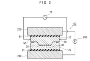
- FIG. 2 is a cross-sectional view showing a use state of the resin molding apparatus according to one embodiment of the present invention.
- FIG. 3 is a diagram showing an energized state of the resin molding apparatus according to one embodiment of the present invention.
- FIG. 4 is a sectional view showing a use state of a resin molding apparatus according to another embodiment of the present invention.
- FIG. 5 is a diagram showing an energized state of a resin molding apparatus according to another embodiment of the present invention.
- FIG. 6 is a view showing a resin molding apparatus according to another embodiment of the present invention.
- FIG. 1 is a schematic view showing the structure of the resin molding apparatus 100.
- the resin molding apparatus 100 includes molds 10 and 20 and a high-frequency current generator 70.
- the molds 10 and 20 are arranged via insulating materials 11 and 21 so as to be insulated from the ground, respectively.
- the pair of molds 10 and 20 are disposed in the press device 200.
- the press device 200 includes a fixed portion 210 that is fixed, and a movable portion 220 that faces the fixed portion 210 in the vertical direction and is movable in the vertical direction.
- the pressing device 200 can forcibly lower the movable portion 220 toward the fixed portion 210 with a required force.
- the upper mold 10 of the pair of molds 10 and 20 is installed on the movable portion 220 with the insulating material 11 interposed therebetween.
- the lower mold 20 is installed on the fixed portion 210 with the insulating material 12 interposed therebetween.
- the upper and lower molds 10 and 20 are insulated from the movable portion 220 and the fixed portion 210 by the insulating materials 11 and 12, respectively.
- the insulating materials 11 and 12 may be formed of an insulating resin material (for example, nylon, Teflon (registered trademark), etc.) or ceramics (for example, alumina, magnesia, etc.).
- the pair of molds 10 and 20 is made of a metal material, in particular, a steel material or cast iron, especially a mold steel, a super hard material, or a conductive ceramic (for example, TiN, Cr2N, CrN, etc.) It has the required rigidity and conductivity.
- a metal material in particular, a steel material or cast iron, especially a mold steel, a super hard material, or a conductive ceramic (for example, TiN, Cr2N, CrN, etc.) It has the required rigidity and conductivity.
- the materials of the insulating materials 11 and 12 and the molds 10 and 20 are not limited to the above materials, and an appropriate material may be selected so as to exhibit a required function.
- the pair of molds 10 and 20 are provided with a molding part 40 on which the resin material 30 is disposed and the resin material 30 is molded.
- electrodes 50 and 60 are provided at two points sandwiching the molding part 40.
- the high-frequency current generator 70 is a device that generates a high-frequency current, and is electrically connected between the electrodes 50 and 60 provided in the mold 10.
- the high-frequency current generator 70 can flow a high-frequency current between the pair of electrodes 50 and 60.
- a device capable of adjusting the frequency and voltage of the high-frequency current is preferably used.
- a high-frequency current generator 70 for example, MK3, MK12, MK15, MK16A, MK18, MK19, MK20, MK22, MK22A, MK24, MK30, MK40, MK50-51, etc., manufactured by High Frequency Thermal Engineering Co., Ltd. may be used. it can.
- the high-frequency current generator 70 is electrically connected between the electrodes 50 and 60 provided on the mold 10. Therefore, the high-frequency current generator 70 may be used in combination with an appropriate tank circuit. The tank circuit is not shown. *
- the resin material 30 is arranged in the molding part 40 with the pair of molds 10 and 20 being opened.
- a resin material including a thermoplastic resin and reinforcing fibers may be used.
- Various resin materials can be used as the resin material 30.
- a resin material in which reinforcing fibers are arranged in a predetermined direction is disposed in the molding part 40 of the mold.
- a preferred example of the resin material 30 is a prepreg in which a reinforcing fiber fabric is impregnated with a thermoplastic resin in advance.
- a reinforcing fiber is impregnated with a thermoplastic resin in advance, and the direction of the reinforcing fiber is held in advance. Further, since the thermoplastic resin is further impregnated into the reinforcing fiber by being reheated when being molded in the mold, the degree of bonding between the reinforcing fiber and the thermoplastic resin is strengthened.
- the composite sheet proposed in Patent Document 1 described above can be used as another suitable example of the resin material 30, for example.
- this composite sheet continuous reinforcing fibers are arranged in a certain direction in each layer and laminated with different directions of continuous reinforcing fibers for each layer, and a nonwoven fabric made of a thermoplastic resin is laminated together with the continuous reinforcing fibers to form a stitch.
- the continuous reinforcing fiber and the nonwoven fabric are integrated.
- such a composite sheet is used as the resin material 30.
- symbol 34 has shown the lamination
- symbol 32 has shown the nonwoven fabric which consists of a thermoplastic resin which was stitched and integrated with the continuous reinforcement fiber.
- a nonwoven fabric 32 made of a thermoplastic resin is superimposed on a laminated portion 34 in which continuous reinforcing fibers are laminated.
- the nonwoven fabric 32 made of a thermoplastic resin may be disposed in the molding portion 40 toward the mold 10 (upper mold).
- the pair of molds 10 and 20 are closed.
- a high frequency current is passed between the pair of electrodes 50, 60 of the mold 10 by the high frequency current generator 70.
- the high-frequency current for example, a high-frequency current having a frequency of 10 kHz or more is preferably passed.
- the high-frequency current is more preferably 100 kHz or higher.
- the high-frequency current is more preferably 400 kHz or less so that an appropriate output can be obtained.
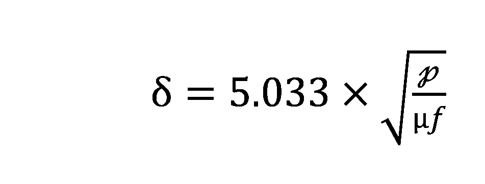
- Equation 1 When a high-frequency current is passed between the pair of electrodes 50 and 60 of the mold 10, as shown in FIG. 3, as a characteristic of the high-frequency current, most of the high-frequency current is a skin portion 16 (a depth from the surface) Sano layer).
- the depth ⁇ (cm) of the skin portion 16 is theoretically obtained by Equation 1.
- ⁇ (cm) is the depth of the layer from the surface through which 73% of the total current flows.
- ⁇ ( ⁇ -cm) is a specific resistance value of the metal used for the mold 10.
- f (Hz) is a frequency.
- ⁇ is the relative permeability.
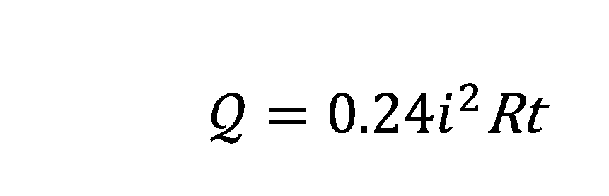
- the amount of heat Q generated in the skin portion 16 is theoretically obtained by Equation 2.
- R ( ⁇ ) represents the resistance value of the skin portion 16
- i (A) represents the current value flowing through the skin portion 16
- t (s) represents the time during which the high-frequency current flowed. Yes.
- Equation 1 the higher the frequency f of the high-frequency current flowing between the pair of electrodes 50 and 60 of the mold 10 by the high-frequency current generator 70, the smaller ⁇ becomes.
- the skin portion 16 through which a large amount of current flows becomes shallow. For this reason, the mold 10 is likely to generate heat on the surface layer.
- a steel material (SUS430 in this embodiment) is used for the mold 10.
- the specific resistance ⁇ ( ⁇ -cm) of the mold 10 is about 60 to 70 ( ⁇ -cm).
- the relative permeability of the mold 10 is about 20.
- a high frequency current of 10 kHz or more flows as the high frequency current.
- the depth ⁇ of the skin portion 16 through which about 63% of the high-frequency current flows is about 0.09 cm or less.
- the higher the frequency of the high-frequency current the shallower the skin portion 16 through which most of the high-frequency current flows, and heat generation at the skin of the mold 10 becomes easier. As shown in FIG.
- the skin portion 16 of the molding part 40 of the mold 10 generates heat by the action of the high-frequency current. At this time, the skin portion 16 of the mold 10 generates heat rapidly.
- the time during which the high-frequency current flows is preferably adjusted to such an extent that the thermoplastic resin in the resin material 30 can be sufficiently melted and molded.
- thermoplastic resin materials include, for example, SKS, SKD, SKT, SKH used as tool steel, SUS, SUH used for special purpose steel, and the like.
- These specific resistances ⁇ ( ⁇ -cm) are about 8 to 120 ( ⁇ -cm), and the relative permeability is about 300 to 1.
- the high-frequency current generator 70 can flow a high-frequency current having a frequency of 10 kHz or more as a high-frequency current through the mold. In this case, since the frequency of the high-frequency current is too high compared to the specific resistance ⁇ ( ⁇ -cm) and the relative permeability of the mold material, as can be seen from the above equation 1, the skin portion where most of the high-frequency current flows.
- the depth ⁇ of 16 is generally determined by the frequency of the high-frequency current flowing through the mold.
- a high-frequency current of 10 kHz or more is passed through the mold, the depth ⁇ of the skin portion 16 through which most of the high-frequency current flows can be reduced to about 0.009 cm or less with a general mold material.
- the resin material 30 can be rapidly heated. Further, the skin portion 16 of the mold 10 generates heat, the inside of the mold 10 is only heated by the heat transfer, and the entire mold 10 is not heated to such an extent that the resin is melted. For this reason, also in a cooling process, cooling of the metal mold
- the cooling structure of the mold 10 is not illustrated, for example, a flow path may be formed in the mold 10 and the mold may be cooled by passing cooling water through the flow path.
- the mold 10 generates heat around the skin portion 16.
- the skin portion 16 of the mold 10 may be at a required temperature required for molding the resin material during molding.
- energization to the mold 10 may be controlled so that the mold 10 does not become so hot except for the skin portion 16. Thereby, it can prevent that the metal mold
- FIG. it is less necessary to consider the temperature dependence on the rigidity of the mold 10. For this reason, even if a large pressure is applied to the mold 10, deformation and damage of the mold 10 can be suppressed.
- this resin molding apparatus 100 since it can shape
- the lower mold 20 has no electrode and is not directly energized, but no short circuit occurs even when electricity flows through the reinforcing mold through the lower mold 20.
- the molds 10 and 20 are electrically insulated, and even when electricity flows to the lower mold 20 through the reinforcing fibers, electricity flows (returns) to the upper mold 10 through the reinforcing fibers as well. A potential difference that causes a short circuit between the mold 10 and the mold 20 does not occur.
- the resin molding apparatus 100 can appropriately heat the resin material 30 placed on the molding unit 40 without causing a short circuit when the molds 10 and 20 are closed.
- the electrodes 50 and 60 provided so as to sandwich the molding part 40 in the upper mold 10 are energized with a high-frequency current.
- the non-conductive fiber such as glass fiber may be used as the reinforcing fiber of the resin material 30, but a highly conductive fiber such as carbon fiber may be used.
- a conductive fiber is used as the reinforcing fiber, a high-frequency current may flow through the resin material 30 through the fiber.
- the upper and lower molds 10 and 20 are completely insulated from the ground by the insulating materials 11 and 12. For this reason, even when a high-frequency current flows through the reinforcing fiber through the resin material 30, electricity returns to the mold 10 through the reinforcing fiber, so that no short circuit occurs.
- the reinforcing fiber itself can generate heat. Furthermore, since the thermoplastic resin is heated around the reinforcing fibers, the viscosity of the resin is lowered and the fluidity of the resin is improved. As a result, the thermoplastic resin is easily impregnated around the reinforcing fibers. Furthermore, the degree of bonding between the reinforcing fiber and the thermoplastic resin is improved, and the mechanical properties of the molded product are also improved.
- electrodes 50, 52, 60, and 62 are provided at two points sandwiching the molding part 40 of the pair of molds 10 and 20, respectively.
- the high-frequency current generator 70 is configured such that the upper mold is connected to a circuit that connects the electrodes 50 and 60 provided so as to sandwich the molding portion 40 between the upper mold 10. 10 may be connected in parallel with electrodes 52 and 62 provided so as to sandwich the molding portion 40 therebetween.
- high-frequency current flows through the upper and lower molds 10 and 20, but the upper and lower molds 10 and 20 are connected in parallel to the high-frequency current generator 70 as described above.
- the resin molding apparatus 100A can appropriately heat the resin material 30 placed on the molding unit 40 without causing a short circuit. In this case, the skin portions 16 of the upper and lower molds 10 and 20 are heated, and the resin material 30 can be heated at an early stage.
- the surfaces of the molding portions 40B of the molds 10B and 20B have an irregular shape.
- dies 10B and 20B are arrange
- the molding portion 40B forms a molding space having a circular cross section by combining the upper and lower molds 10B and 20B.
- the high-frequency current generator 70 is connected in parallel to the two electrodes 50, 52, 60, 62 that sandwich the molding part 40B of the pair of molds 10B, 20B.
- the skin part of the molding part 40B of the molds 10B and 20B is heated by utilizing the property that high-frequency current flows in the skin part of the molding part 40B of the molds 10B and 20B.
- the skin part of the molding part 40B is appropriately heated regardless of the shape of the molding part 40B. Therefore, molding is possible even if the shape of the molded product is an irregular shape.
- this resin molding apparatus since there is a degree of freedom in arrangement of the electrodes, it is possible to design a mold considering only its shape without considering the thickness of the molded product. For this reason, the shape of the molded product is also highly flexible.
- the resin molding apparatus includes a pair of molds 10 and 20 disposed via the insulating materials 11 and 21 so as to be insulated from the ground, and a pair of molds. 10 and 20, and a molding portion 40 in which the resin material 30 is disposed is provided. At least one of the pair of molds 10 and 20 is provided with electrodes 50 and 60 at two points sandwiching the molding part 40. The two electrodes 50 and 60 are connected to a high-frequency current generator 70 that can flow a high-frequency current having a frequency of 10 kHz or more.
- the resin material 30 is disposed in the molding part 40 and the molds 10 and 20 are closed.
- a high frequency voltage can be applied to the molds 10 and 20.
- the molds 10 and 20 are provided with a pair of electrodes 50 and 60 at two points sandwiching the molding part 40, and a high frequency current generator 70 connected to the electrodes 50 and 60 has a high frequency of 10 kHz or more. A current flows.
- the resin molding apparatus can heat the resin material 30 efficiently. Further, in this resin molding apparatus 100, since the surfaces of the molds 10 and 20 are particularly heated, the time required for cooling the molds 10 and 20 can be shortened, and the molding cycle as a whole can be shortened.
- the movable mold may be made thinner than the fixed mold to reduce the weight. In this case, it is possible to reduce the burden on a drive device (for example, a press device) that drives the movable mold. Thereby, the energy cost of resin molding can be reduced.
- the fiber reinforced thermoplastic composite material is exemplified as the thermoplastic resin material.
- a fiber reinforced thermoplastic composite material for example, as disclosed in Japanese Patent No. 3947560 (Patent Document 1), a composite sheet in which a nonwoven fabric made of a thermoplastic resin and continuous reinforcing fibers are integrated. Is included.
- thermoplastic resin material examples include a fiber-reinforced thermoplastic composite material.
- examples of the reinforcing fibers contained in the fiber-reinforced thermoplastic composite material include carbon fibers and glass fibers.
- the reinforcing fiber contained in the fiber-reinforced thermoplastic composite material is not limited to this, and may be a plant-derived fiber, for example.
- thermoplastic resin material is not limited to the above, but includes various thermoplastic resin materials.
- thermoplastic resin material suitable for being molded by the resin molding apparatus and the resin molding method according to the present invention include polyolefin resins such as polyethylene and polypropylene, nylon 6, nylon 66, nylon 12, and nylon 46.
Landscapes
- Engineering & Computer Science (AREA)
- Mechanical Engineering (AREA)
- Moulds For Moulding Plastics Or The Like (AREA)
- Casting Or Compression Moulding Of Plastics Or The Like (AREA)
Abstract
Description
11、12 絶縁材
16、 表皮部分
20、20B 金型
30 複合シート(樹脂材料)
32 不織布
34 積層部
40、40B 成形部
50、52、60、62 電極
70 高周波電流発生装置
100、100A、100B 樹脂成形装置
200 プレス装置
210 固定部
220 可動部 10,
32
Claims (3)
- 熱可塑性の樹脂材料をプレス成形する樹脂成形装置であって、
それぞれグランドから絶縁されるように絶縁材を介して配置された一対の金型と、
前記一対の金型によって形成され、前記樹脂材料が配置される成形部と、
前記一対の金型のうち少なくとも一方の金型において、前記成形部を挟む2点に設けられた電極と、
前記成形部を挟む2つの電極に電気的に接続され、前記電極間に周波数が10kHz以上の高周波電流を流すことができる高周波電流発生装置と、
を備えた、樹脂成形装置。 A resin molding apparatus for press molding a thermoplastic resin material,
A pair of molds arranged via an insulating material so as to be insulated from the ground,
A molding part formed by the pair of molds, in which the resin material is disposed;
In at least one of the pair of molds, electrodes provided at two points sandwiching the molding part;
A high-frequency current generator that is electrically connected to two electrodes sandwiching the molded part, and that allows a high-frequency current having a frequency of 10 kHz or more to flow between the electrodes;
A resin molding apparatus comprising: - 前記一対の金型は、それぞれ前記成形部を挟む2点に電極が設けられており、
前記高周波電流発生装置は、一対の金型の成形部を挟む2つの電極に並列に接続されている、請求項1に記載の樹脂成形装置。 Each of the pair of molds is provided with electrodes at two points sandwiching the molding part,
The resin molding apparatus according to claim 1, wherein the high-frequency current generator is connected in parallel to two electrodes sandwiching a molding part of a pair of molds. - それぞれグランドから絶縁されるように絶縁材を介して配置された一対の金型の成形部に、熱可塑性の樹脂材料を配置する工程と、
前記一対の金型に設けた電極を通じて、前記一対の金型に周波数が10kHz以上の高周波電流を流すことによって、前記一対の金型を加熱して、前記成形部に配置された樹脂材料を成形する工程と、
を備えた樹脂成形方法。 A step of disposing a thermoplastic resin material in a molding part of a pair of molds disposed via an insulating material so as to be insulated from each ground;
By passing a high-frequency current having a frequency of 10 kHz or more to the pair of molds through the electrodes provided on the pair of molds, the pair of molds is heated to mold the resin material disposed in the molding part. And the process of
A resin molding method comprising:
Priority Applications (4)
| Application Number | Priority Date | Filing Date | Title |
|---|---|---|---|
| EP10750882.2A EP2407295B1 (en) | 2009-03-12 | 2010-03-10 | Resin molding apparatus and resin molding method |
| JP2011503848A JP5696992B2 (en) | 2009-03-12 | 2010-03-10 | Resin molding apparatus and resin molding method |
| US13/255,586 US9370884B2 (en) | 2009-03-12 | 2010-03-10 | Resin molding apparatus and resin molding method |
| KR1020117021594A KR101291263B1 (en) | 2009-03-12 | 2010-03-10 | Resin molding apparatus and resin molding method |
Applications Claiming Priority (2)
| Application Number | Priority Date | Filing Date | Title |
|---|---|---|---|
| JP2009060143 | 2009-03-12 | ||
| JP2009-060143 | 2009-03-12 |
Publications (1)
| Publication Number | Publication Date |
|---|---|
| WO2010104129A1 true WO2010104129A1 (en) | 2010-09-16 |
Family
ID=42728417
Family Applications (1)
| Application Number | Title | Priority Date | Filing Date |
|---|---|---|---|
| PCT/JP2010/054046 WO2010104129A1 (en) | 2009-03-12 | 2010-03-10 | Resin molding apparatus and resin molding method |
Country Status (5)
| Country | Link |
|---|---|
| US (1) | US9370884B2 (en) |
| EP (1) | EP2407295B1 (en) |
| JP (1) | JP5696992B2 (en) |
| KR (1) | KR101291263B1 (en) |
| WO (1) | WO2010104129A1 (en) |
Cited By (7)
| Publication number | Priority date | Publication date | Assignee | Title |
|---|---|---|---|---|
| KR101252730B1 (en) * | 2010-12-24 | 2013-04-10 | 조치형 | Molding apparatus and molding method using the same |
| CN103072222A (en) * | 2011-10-25 | 2013-05-01 | 昆山渝榕电子有限公司 | Die with heating device |
| JP2013086508A (en) * | 2011-10-19 | 2013-05-13 | Kunshan yurong electronics co ltd | Mold with heating device |
| JP2013203020A (en) * | 2012-03-29 | 2013-10-07 | Toho Tenax Co Ltd | Method of manufacturing composite molding |
| JP2016510692A (en) * | 2013-09-24 | 2016-04-11 | テーエムデー フリクション サービシス ゲーエムベーハー | Manufacturing method of press tool and friction lining |
| TWI600521B (en) * | 2016-12-19 | 2017-10-01 | 中原大學 | Molding structure and heating method thereof |
| JP2017177695A (en) * | 2016-03-31 | 2017-10-05 | マツダ株式会社 | Apparatus and method for injection molding |
Families Citing this family (20)
| Publication number | Priority date | Publication date | Assignee | Title |
|---|---|---|---|---|
| CN103287009B (en) * | 2012-02-24 | 2015-03-25 | 比亚迪股份有限公司 | Preparation method of aluminum alloy-resin composite and aluminum alloy-resin composite prepared by using same |
| CN103286996B (en) | 2012-02-24 | 2015-03-25 | 比亚迪股份有限公司 | Preparation method of aluminum alloy-resin composite and aluminum alloy-resin composite prepared by using same |
| CN103286909B (en) | 2012-02-24 | 2015-09-30 | 比亚迪股份有限公司 | A kind of metal-resin integrated molding method and a kind of metal-resin composite |
| CN103286995B (en) | 2012-02-24 | 2015-06-24 | 比亚迪股份有限公司 | Preparation method of aluminum alloy-resin composite and aluminum alloy-resin composite prepared by using same |
| CN104780241B (en) | 2012-02-24 | 2018-06-26 | 比亚迪股份有限公司 | A kind of handset shell |
| CN103286910B (en) | 2012-02-24 | 2015-09-30 | 比亚迪股份有限公司 | A kind of metal-resin integrated molding method and a kind of metal-resin composite |
| CN103286908B (en) * | 2012-02-24 | 2015-09-30 | 比亚迪股份有限公司 | A kind of metal-resin integrated molding method and a kind of metal-resin composite |
| WO2013178057A1 (en) | 2012-05-28 | 2013-12-05 | Shenzhen Byd Auto R&D Company Limited | Metal composite and method of preparing the same, metal-resin composite and method of preparing the same |
| TWI565105B (en) * | 2012-07-09 | 2017-01-01 | 山田尖端科技股份有限公司 | Resin molding apparatus and method for resin molding |
| US9801294B2 (en) * | 2012-11-29 | 2017-10-24 | Sunteng New Technology Co., Ltd. | Electronic device casing including coupling structure and method of manufacturing same |
| CN104746066B (en) | 2013-12-31 | 2017-07-04 | 比亚迪股份有限公司 | Bond material of a kind of metal and plastics and preparation method thereof and the bond material for preparing |
| CN104827608B (en) * | 2014-02-11 | 2017-11-07 | 刘忠男 | Has the mould of heater |
| TWI625212B (en) * | 2014-02-11 | 2018-06-01 | 劉忠男 | Mould with a heating device |
| JP6607556B2 (en) * | 2015-06-03 | 2019-11-20 | 三菱重工業株式会社 | Apparatus and method for curing resin composite material |
| US20170217056A1 (en) * | 2016-01-29 | 2017-08-03 | Dell Products L.P. | Carbon Fiber Information Handling System Housing and Process for Manufacture |
| WO2017168920A1 (en) * | 2016-03-30 | 2017-10-05 | バンドー化学株式会社 | Method for manufacturing belt and cylindrical mold and bridging device used therefor |
| JP2019126923A (en) * | 2018-01-22 | 2019-08-01 | トヨタ自動車株式会社 | Molding die, molding apparatus, molding method, and manufacturing method of resin product |
| CN111886120B (en) * | 2018-03-30 | 2022-05-31 | 马自达汽车株式会社 | Resin material for injection molding |
| CN110900902B (en) * | 2019-12-09 | 2022-04-15 | 宋顺升 | Cold and hot integrative rubber and plastic steady type machine |
| US11628628B2 (en) * | 2020-05-26 | 2023-04-18 | Spirit Aerosystems, Inc. | Method of manufacturing simple curvature thermoplastic composite parts |
Citations (3)
| Publication number | Priority date | Publication date | Assignee | Title |
|---|---|---|---|---|
| JPS4614155B1 (en) * | 1967-06-13 | 1971-04-15 | ||
| JP2003311799A (en) * | 2002-04-22 | 2003-11-05 | Ricoh Co Ltd | Method and apparatus for molding thin plastic molded product |
| JP2006256078A (en) * | 2005-03-17 | 2006-09-28 | Ricoh Co Ltd | Press molding apparatus, press molding method using the apparatus, and resin molding formed by the apparatus |
Family Cites Families (29)
| Publication number | Priority date | Publication date | Assignee | Title |
|---|---|---|---|---|
| US2979773A (en) * | 1959-08-26 | 1961-04-18 | Honeywell Regulator Co | Molding apparatus |
| FR1584599A (en) * | 1968-07-23 | 1969-12-26 | ||
| GB1278642A (en) * | 1969-06-04 | 1972-06-21 | Fibreglass Ltd | Improvements in and relating to the manufacture of bonded fibrous bodies |
| US4423191A (en) * | 1981-05-01 | 1983-12-27 | Massachusetts Institute Of Technology | High frequency electric field curing of polymeric composites |
| US4496131A (en) * | 1982-01-07 | 1985-01-29 | Yang Wen Jei | Apparatus for injection molding a foamed resin product having a smooth surface involving surface heating of the mold by applying high current low voltage electric power |
| DE3444525A1 (en) | 1984-12-06 | 1986-06-19 | Vdo Adolf Schindling Ag, 6000 Frankfurt | LIQUID CRYSTAL CELL |
| US5041247A (en) * | 1988-09-29 | 1991-08-20 | General Electric Company | Method and apparatus for blow molding parts with smooth surfaces |
| US5176839A (en) * | 1991-03-28 | 1993-01-05 | General Electric Company | Multilayered mold structure for hot surface molding in a short cycle time |
| US5227180A (en) * | 1991-10-07 | 1993-07-13 | Tisack Michael D | Apparatus for applying an electric field |
| US20040036201A1 (en) * | 2000-07-18 | 2004-02-26 | Princeton University | Methods and apparatus of field-induced pressure imprint lithography |
| JP3874511B2 (en) * | 1996-12-03 | 2007-01-31 | 日世株式会社 | Method for producing starch biodegradable molding |
| JP3982888B2 (en) * | 1996-12-16 | 2007-09-26 | 日世株式会社 | Method and apparatus for producing biodegradable molded product |
| US6612826B1 (en) * | 1997-10-15 | 2003-09-02 | Iap Research, Inc. | System for consolidating powders |
| US8852494B2 (en) * | 1999-10-08 | 2014-10-07 | Princeton University | Method and apparatus of electrical field assisted imprinting |
| FR2816237B1 (en) * | 2000-11-08 | 2003-09-19 | Roctool | MOLDS FOR PROCESSING PLASTICS AND COMPOSITES AND ASSOCIATED PROCESSING METHOD |
| DE10108570C2 (en) * | 2001-02-22 | 2003-05-28 | Laeis & Bucher Gmbh | Method and device for producing a shaped body |
| US20040046281A1 (en) * | 2002-09-06 | 2004-03-11 | Byung Kim | Localized compression molding process for fabricating microstructures on thermoplastic substrates |
| JP4339003B2 (en) * | 2003-04-02 | 2009-10-07 | ジャパンスーパークォーツ株式会社 | Method for producing quartz glass crucible |
| GB0311494D0 (en) * | 2003-05-20 | 2003-06-25 | Stanelco Fibre Optics Ltd | Making foamed bodies |
| FR2867939B1 (en) * | 2004-03-18 | 2007-08-10 | Roctool | METHOD FOR HEATING MATERIALS TO PRODUCE OBJECTS AND DEVICE USING THE METHOD |
| TWI235628B (en) * | 2004-03-26 | 2005-07-01 | Ind Tech Res Inst | Monitoring system and method for imprint process |
| EP1923192A4 (en) | 2005-07-29 | 2010-09-15 | Doshisha | Method for molding fiber-reinforced thermoplastic composite material, intermediate thereof and composite sheet |
| TWI279304B (en) * | 2005-10-04 | 2007-04-21 | Chien Hui Chuan | The method and apparatus for heating mold by high frequency current |
| TW200821159A (en) * | 2006-11-07 | 2008-05-16 | Benq Corp | Paper kicker for exit roller and printer utilizing the same |
| US8021135B2 (en) * | 2007-06-08 | 2011-09-20 | Sabic Innovative Plastics Ip B.V. | Mold apparatus for forming polymer and method |
| US8375758B1 (en) * | 2007-09-13 | 2013-02-19 | The Boeing Company | Induction forming of metal components with slotted susceptors |
| US8372327B2 (en) * | 2007-09-13 | 2013-02-12 | The Boeing Company | Method for resin transfer molding composite parts |
| JP5107417B2 (en) * | 2010-12-24 | 2012-12-26 | 株式会社キャップ | Molding apparatus and molding method using the molding apparatus |
| TWI513565B (en) * | 2011-10-19 | 2015-12-21 | Kunshan yurong electronics co ltd | Mould with a heating device |
-
2010
- 2010-03-10 EP EP10750882.2A patent/EP2407295B1/en active Active
- 2010-03-10 JP JP2011503848A patent/JP5696992B2/en not_active Expired - Fee Related
- 2010-03-10 US US13/255,586 patent/US9370884B2/en active Active
- 2010-03-10 WO PCT/JP2010/054046 patent/WO2010104129A1/en active Application Filing
- 2010-03-10 KR KR1020117021594A patent/KR101291263B1/en active IP Right Grant
Patent Citations (3)
| Publication number | Priority date | Publication date | Assignee | Title |
|---|---|---|---|---|
| JPS4614155B1 (en) * | 1967-06-13 | 1971-04-15 | ||
| JP2003311799A (en) * | 2002-04-22 | 2003-11-05 | Ricoh Co Ltd | Method and apparatus for molding thin plastic molded product |
| JP2006256078A (en) * | 2005-03-17 | 2006-09-28 | Ricoh Co Ltd | Press molding apparatus, press molding method using the apparatus, and resin molding formed by the apparatus |
Cited By (9)
| Publication number | Priority date | Publication date | Assignee | Title |
|---|---|---|---|---|
| KR101252730B1 (en) * | 2010-12-24 | 2013-04-10 | 조치형 | Molding apparatus and molding method using the same |
| JP2013086508A (en) * | 2011-10-19 | 2013-05-13 | Kunshan yurong electronics co ltd | Mold with heating device |
| KR101420762B1 (en) * | 2011-10-19 | 2014-07-17 | 류충난 | Mould assembly with a heating device |
| CN103072222A (en) * | 2011-10-25 | 2013-05-01 | 昆山渝榕电子有限公司 | Die with heating device |
| JP2013203020A (en) * | 2012-03-29 | 2013-10-07 | Toho Tenax Co Ltd | Method of manufacturing composite molding |
| JP2016510692A (en) * | 2013-09-24 | 2016-04-11 | テーエムデー フリクション サービシス ゲーエムベーハー | Manufacturing method of press tool and friction lining |
| US9956737B2 (en) | 2013-09-24 | 2018-05-01 | Tmd Friction Services Gmbh | Device and method for the production of friction linings and brake linings |
| JP2017177695A (en) * | 2016-03-31 | 2017-10-05 | マツダ株式会社 | Apparatus and method for injection molding |
| TWI600521B (en) * | 2016-12-19 | 2017-10-01 | 中原大學 | Molding structure and heating method thereof |
Also Published As
| Publication number | Publication date |
|---|---|
| EP2407295A1 (en) | 2012-01-18 |
| JPWO2010104129A1 (en) | 2012-09-13 |
| EP2407295B1 (en) | 2019-06-12 |
| EP2407295A4 (en) | 2016-12-28 |
| US20120168990A1 (en) | 2012-07-05 |
| US9370884B2 (en) | 2016-06-21 |
| KR101291263B1 (en) | 2013-07-30 |
| KR20110127697A (en) | 2011-11-25 |
| JP5696992B2 (en) | 2015-04-08 |
Similar Documents
| Publication | Publication Date | Title |
|---|---|---|
| JP5696992B2 (en) | Resin molding apparatus and resin molding method | |
| CN101909839B (en) | System and method for forming polymer | |
| KR20120139750A (en) | Preform and method for manufacturing the same | |
| US10369750B2 (en) | Device and process for welding thermoplastic composite material parts | |
| KR101252730B1 (en) | Molding apparatus and molding method using the same | |
| JP2016153237A (en) | Device and method for heating mould or tool | |
| US9539770B2 (en) | Flexible membrane for the production of parts made from composite materials | |
| EP2909012B1 (en) | Compliant layer for matched tool molding of uneven composite preforms | |
| JP2004516953A (en) | Molds for deforming plastic and composite materials and related deformation methods | |
| KR20190089715A (en) | Molding die, molding apparatus, molding method, and manufacturing method for resin product | |
| JP5443138B2 (en) | Apparatus and method for molding composite laminate material body | |
| JP7227342B2 (en) | Mold with thermally conductive flange | |
| JP2012224016A (en) | Shaping and molding method, and fiber-reinforced resin molded article | |
| JP6432750B2 (en) | Fiber reinforced composite material molding equipment | |
| JP7350255B2 (en) | Manufacturing method for foamed resin molded products | |
| JP6610859B2 (en) | Composite member and method for manufacturing the composite member | |
| CN117940272A (en) | Molding apparatus | |
| JP2014034173A (en) | Method for manufacturing a resin molding | |
| JP2011005691A (en) | Mold and method for compression molding |
Legal Events
| Date | Code | Title | Description |
|---|---|---|---|
| 121 | Ep: the epo has been informed by wipo that ep was designated in this application |
Ref document number: 10750882 Country of ref document: EP Kind code of ref document: A1 |
|
| DPE2 | Request for preliminary examination filed before expiration of 19th month from priority date (pct application filed from 20040101) | ||
| WWE | Wipo information: entry into national phase |
Ref document number: 2011503848 Country of ref document: JP |
|
| WWE | Wipo information: entry into national phase |
Ref document number: 13255586 Country of ref document: US |
|
| NENP | Non-entry into the national phase |
Ref country code: DE |
|
| ENP | Entry into the national phase |
Ref document number: 20117021594 Country of ref document: KR Kind code of ref document: A |
|
| WWE | Wipo information: entry into national phase |
Ref document number: 2010750882 Country of ref document: EP |