WO2010090279A1 - Disposable chip-type flow cell and flow cytometer using same - Google Patents
Disposable chip-type flow cell and flow cytometer using same Download PDFInfo
- Publication number
- WO2010090279A1 WO2010090279A1 PCT/JP2010/051694 JP2010051694W WO2010090279A1 WO 2010090279 A1 WO2010090279 A1 WO 2010090279A1 JP 2010051694 W JP2010051694 W JP 2010051694W WO 2010090279 A1 WO2010090279 A1 WO 2010090279A1
- Authority
- WO
- WIPO (PCT)
- Prior art keywords
- flow
- flow path
- flow cell
- light
- cell
- Prior art date
Links
- 239000007788 liquid Substances 0.000 claims abstract description 222
- 239000002245 particle Substances 0.000 claims abstract description 183
- 239000000758 substrate Substances 0.000 claims abstract description 82
- 230000001678 irradiating effect Effects 0.000 claims abstract description 31
- 239000000523 sample Substances 0.000 claims description 163
- 238000000926 separation method Methods 0.000 claims description 85
- 238000000034 method Methods 0.000 claims description 78
- 239000010419 fine particle Substances 0.000 claims description 68
- 239000012488 sample solution Substances 0.000 claims description 55
- 238000001514 detection method Methods 0.000 claims description 35
- 230000003287 optical effect Effects 0.000 claims description 35
- 239000006249 magnetic particle Substances 0.000 claims description 28
- 238000011144 upstream manufacturing Methods 0.000 claims description 24
- 238000003384 imaging method Methods 0.000 claims description 14
- 239000002699 waste material Substances 0.000 claims description 13
- 239000000463 material Substances 0.000 claims description 12
- 238000006243 chemical reaction Methods 0.000 claims description 11
- 230000004044 response Effects 0.000 claims description 8
- 230000002776 aggregation Effects 0.000 claims description 7
- 238000004220 aggregation Methods 0.000 claims description 7
- 238000003320 cell separation method Methods 0.000 claims description 6
- 238000004458 analytical method Methods 0.000 claims description 5
- 239000006185 dispersion Substances 0.000 claims description 4
- 230000007246 mechanism Effects 0.000 claims description 4
- 210000004027 cell Anatomy 0.000 abstract description 348
- 239000011859 microparticle Substances 0.000 abstract description 3
- 238000005259 measurement Methods 0.000 description 36
- 239000000243 solution Substances 0.000 description 16
- YBJHBAHKTGYVGT-ZKWXMUAHSA-N (+)-Biotin Chemical compound N1C(=O)N[C@@H]2[C@H](CCCCC(=O)O)SC[C@@H]21 YBJHBAHKTGYVGT-ZKWXMUAHSA-N 0.000 description 12
- 230000006870 function Effects 0.000 description 10
- 239000000427 antigen Substances 0.000 description 9
- 102000036639 antigens Human genes 0.000 description 9
- 108091007433 antigens Proteins 0.000 description 9
- 239000011347 resin Substances 0.000 description 9
- 229920005989 resin Polymers 0.000 description 9
- 230000005684 electric field Effects 0.000 description 8
- 239000002122 magnetic nanoparticle Substances 0.000 description 8
- 229960002685 biotin Drugs 0.000 description 6
- 235000020958 biotin Nutrition 0.000 description 6
- 239000011616 biotin Substances 0.000 description 6
- 239000012530 fluid Substances 0.000 description 6
- 239000010453 quartz Substances 0.000 description 6
- VYPSYNLAJGMNEJ-UHFFFAOYSA-N silicon dioxide Inorganic materials O=[Si]=O VYPSYNLAJGMNEJ-UHFFFAOYSA-N 0.000 description 6
- NIXOWILDQLNWCW-UHFFFAOYSA-N acrylic acid group Chemical group C(C=C)(=O)O NIXOWILDQLNWCW-UHFFFAOYSA-N 0.000 description 5
- 238000007885 magnetic separation Methods 0.000 description 5
- 238000012545 processing Methods 0.000 description 5
- 239000004065 semiconductor Substances 0.000 description 5
- 108010052285 Membrane Proteins Proteins 0.000 description 4
- 102000018697 Membrane Proteins Human genes 0.000 description 4
- 239000008280 blood Substances 0.000 description 4
- 210000004369 blood Anatomy 0.000 description 4
- 238000010586 diagram Methods 0.000 description 4
- 238000001746 injection moulding Methods 0.000 description 4
- 230000008569 process Effects 0.000 description 4
- 238000011084 recovery Methods 0.000 description 4
- 230000004931 aggregating effect Effects 0.000 description 3
- 230000008901 benefit Effects 0.000 description 3
- 239000007853 buffer solution Substances 0.000 description 3
- 238000001917 fluorescence detection Methods 0.000 description 3
- 230000005499 meniscus Effects 0.000 description 3
- 108090001008 Avidin Proteins 0.000 description 2
- 108010090804 Streptavidin Proteins 0.000 description 2
- 241000700605 Viruses Species 0.000 description 2
- 239000000443 aerosol Substances 0.000 description 2
- 239000003153 chemical reaction reagent Substances 0.000 description 2
- 239000000356 contaminant Substances 0.000 description 2
- 238000006073 displacement reaction Methods 0.000 description 2
- 239000003792 electrolyte Substances 0.000 description 2
- 239000007850 fluorescent dye Substances 0.000 description 2
- 239000011521 glass Substances 0.000 description 2
- 230000031700 light absorption Effects 0.000 description 2
- 238000004519 manufacturing process Methods 0.000 description 2
- 239000000203 mixture Substances 0.000 description 2
- 239000013307 optical fiber Substances 0.000 description 2
- 238000003825 pressing Methods 0.000 description 2
- 239000000126 substance Substances 0.000 description 2
- 229920000208 temperature-responsive polymer Polymers 0.000 description 2
- XLYOFNOQVPJJNP-UHFFFAOYSA-N water Substances O XLYOFNOQVPJJNP-UHFFFAOYSA-N 0.000 description 2
- 241000894006 Bacteria Species 0.000 description 1
- 230000005653 Brownian motion process Effects 0.000 description 1
- 101000738771 Homo sapiens Receptor-type tyrosine-protein phosphatase C Proteins 0.000 description 1
- 102000011782 Keratins Human genes 0.000 description 1
- 108010076876 Keratins Proteins 0.000 description 1
- 206010027476 Metastases Diseases 0.000 description 1
- 206010028980 Neoplasm Diseases 0.000 description 1
- 102100037422 Receptor-type tyrosine-protein phosphatase C Human genes 0.000 description 1
- 238000000149 argon plasma sintering Methods 0.000 description 1
- 238000003491 array Methods 0.000 description 1
- 239000013060 biological fluid Substances 0.000 description 1
- 238000005537 brownian motion Methods 0.000 description 1
- 239000000872 buffer Substances 0.000 description 1
- 201000011510 cancer Diseases 0.000 description 1
- 230000003915 cell function Effects 0.000 description 1
- 230000008859 change Effects 0.000 description 1
- 239000011248 coating agent Substances 0.000 description 1
- 238000000576 coating method Methods 0.000 description 1
- 238000011109 contamination Methods 0.000 description 1
- 230000008602 contraction Effects 0.000 description 1
- 238000007796 conventional method Methods 0.000 description 1
- 238000005520 cutting process Methods 0.000 description 1
- 230000007423 decrease Effects 0.000 description 1
- 230000006866 deterioration Effects 0.000 description 1
- 238000009826 distribution Methods 0.000 description 1
- 238000005868 electrolysis reaction Methods 0.000 description 1
- 210000002919 epithelial cell Anatomy 0.000 description 1
- 238000007667 floating Methods 0.000 description 1
- 238000000684 flow cytometry Methods 0.000 description 1
- MHMNJMPURVTYEJ-UHFFFAOYSA-N fluorescein-5-isothiocyanate Chemical group O1C(=O)C2=CC(N=C=S)=CC=C2C21C1=CC=C(O)C=C1OC1=CC(O)=CC=C21 MHMNJMPURVTYEJ-UHFFFAOYSA-N 0.000 description 1
- 239000012634 fragment Substances 0.000 description 1
- 239000000383 hazardous chemical Substances 0.000 description 1
- 238000009532 heart rate measurement Methods 0.000 description 1
- 150000002500 ions Chemical class 0.000 description 1
- 239000011159 matrix material Substances 0.000 description 1
- 238000000691 measurement method Methods 0.000 description 1
- 239000012528 membrane Substances 0.000 description 1
- 230000009401 metastasis Effects 0.000 description 1
- 230000005012 migration Effects 0.000 description 1
- 238000013508 migration Methods 0.000 description 1
- 230000001717 pathogenic effect Effects 0.000 description 1
- 239000004417 polycarbonate Substances 0.000 description 1
- 229920000515 polycarbonate Polymers 0.000 description 1
- 230000035485 pulse pressure Effects 0.000 description 1
- 238000003908 quality control method Methods 0.000 description 1
- -1 respectively Substances 0.000 description 1
- 230000035945 sensitivity Effects 0.000 description 1
- 239000000725 suspension Substances 0.000 description 1
- 238000013519 translation Methods 0.000 description 1
Images


Classifications
-
- G—PHYSICS
- G01—MEASURING; TESTING
- G01N—INVESTIGATING OR ANALYSING MATERIALS BY DETERMINING THEIR CHEMICAL OR PHYSICAL PROPERTIES
- G01N33/00—Investigating or analysing materials by specific methods not covered by groups G01N1/00 - G01N31/00
- G01N33/48—Biological material, e.g. blood, urine; Haemocytometers
- G01N33/483—Physical analysis of biological material
- G01N33/487—Physical analysis of biological material of liquid biological material
- G01N33/49—Blood
- G01N33/4915—Blood using flow cells
-
- G—PHYSICS
- G01—MEASURING; TESTING
- G01N—INVESTIGATING OR ANALYSING MATERIALS BY DETERMINING THEIR CHEMICAL OR PHYSICAL PROPERTIES
- G01N15/00—Investigating characteristics of particles; Investigating permeability, pore-volume or surface-area of porous materials
- G01N15/10—Investigating individual particles
- G01N15/14—Optical investigation techniques, e.g. flow cytometry
- G01N15/1484—Optical investigation techniques, e.g. flow cytometry microstructural devices
-
- G—PHYSICS
- G01—MEASURING; TESTING
- G01N—INVESTIGATING OR ANALYSING MATERIALS BY DETERMINING THEIR CHEMICAL OR PHYSICAL PROPERTIES
- G01N15/00—Investigating characteristics of particles; Investigating permeability, pore-volume or surface-area of porous materials
- G01N15/10—Investigating individual particles
- G01N15/14—Optical investigation techniques, e.g. flow cytometry
- G01N15/1404—Handling flow, e.g. hydrodynamic focusing
-
- G—PHYSICS
- G01—MEASURING; TESTING
- G01N—INVESTIGATING OR ANALYSING MATERIALS BY DETERMINING THEIR CHEMICAL OR PHYSICAL PROPERTIES
- G01N15/00—Investigating characteristics of particles; Investigating permeability, pore-volume or surface-area of porous materials
- G01N15/10—Investigating individual particles
- G01N15/14—Optical investigation techniques, e.g. flow cytometry
- G01N15/1434—Optical arrangements
- G01N15/1436—Optical arrangements the optical arrangement forming an integrated apparatus with the sample container, e.g. a flow cell
-
- G—PHYSICS
- G01—MEASURING; TESTING
- G01N—INVESTIGATING OR ANALYSING MATERIALS BY DETERMINING THEIR CHEMICAL OR PHYSICAL PROPERTIES
- G01N15/00—Investigating characteristics of particles; Investigating permeability, pore-volume or surface-area of porous materials
- G01N15/10—Investigating individual particles
- G01N15/14—Optical investigation techniques, e.g. flow cytometry
- G01N15/1456—Optical investigation techniques, e.g. flow cytometry without spatial resolution of the texture or inner structure of the particle, e.g. processing of pulse signals
- G01N15/1459—Optical investigation techniques, e.g. flow cytometry without spatial resolution of the texture or inner structure of the particle, e.g. processing of pulse signals the analysis being performed on a sample stream
-
- G—PHYSICS
- G01—MEASURING; TESTING
- G01N—INVESTIGATING OR ANALYSING MATERIALS BY DETERMINING THEIR CHEMICAL OR PHYSICAL PROPERTIES
- G01N33/00—Investigating or analysing materials by specific methods not covered by groups G01N1/00 - G01N31/00
- G01N33/48—Biological material, e.g. blood, urine; Haemocytometers
- G01N33/483—Physical analysis of biological material
- G01N33/4833—Physical analysis of biological material of solid biological material, e.g. tissue samples, cell cultures
-
- G—PHYSICS
- G01—MEASURING; TESTING
- G01N—INVESTIGATING OR ANALYSING MATERIALS BY DETERMINING THEIR CHEMICAL OR PHYSICAL PROPERTIES
- G01N33/00—Investigating or analysing materials by specific methods not covered by groups G01N1/00 - G01N31/00
- G01N33/48—Biological material, e.g. blood, urine; Haemocytometers
- G01N33/50—Chemical analysis of biological material, e.g. blood, urine; Testing involving biospecific ligand binding methods; Immunological testing
- G01N33/53—Immunoassay; Biospecific binding assay; Materials therefor
- G01N33/569—Immunoassay; Biospecific binding assay; Materials therefor for microorganisms, e.g. protozoa, bacteria, viruses
- G01N33/56966—Animal cells
-
- G—PHYSICS
- G01—MEASURING; TESTING
- G01N—INVESTIGATING OR ANALYSING MATERIALS BY DETERMINING THEIR CHEMICAL OR PHYSICAL PROPERTIES
- G01N15/00—Investigating characteristics of particles; Investigating permeability, pore-volume or surface-area of porous materials
- G01N15/10—Investigating individual particles
- G01N15/14—Optical investigation techniques, e.g. flow cytometry
- G01N15/1404—Handling flow, e.g. hydrodynamic focusing
- G01N15/1409—Handling samples, e.g. injecting samples
-
- G—PHYSICS
- G01—MEASURING; TESTING
- G01N—INVESTIGATING OR ANALYSING MATERIALS BY DETERMINING THEIR CHEMICAL OR PHYSICAL PROPERTIES
- G01N15/00—Investigating characteristics of particles; Investigating permeability, pore-volume or surface-area of porous materials
- G01N15/10—Investigating individual particles
- G01N15/14—Optical investigation techniques, e.g. flow cytometry
- G01N15/1425—Optical investigation techniques, e.g. flow cytometry using an analyser being characterised by its control arrangement
- G01N15/1427—Optical investigation techniques, e.g. flow cytometry using an analyser being characterised by its control arrangement with the synchronisation of components, a time gate for operation of components, or suppression of particle coincidences
-
- G—PHYSICS
- G01—MEASURING; TESTING
- G01N—INVESTIGATING OR ANALYSING MATERIALS BY DETERMINING THEIR CHEMICAL OR PHYSICAL PROPERTIES
- G01N15/00—Investigating characteristics of particles; Investigating permeability, pore-volume or surface-area of porous materials
- G01N15/10—Investigating individual particles
- G01N15/14—Optical investigation techniques, e.g. flow cytometry
- G01N15/149—Optical investigation techniques, e.g. flow cytometry specially adapted for sorting particles, e.g. by their size or optical properties
-
- G—PHYSICS
- G01—MEASURING; TESTING
- G01N—INVESTIGATING OR ANALYSING MATERIALS BY DETERMINING THEIR CHEMICAL OR PHYSICAL PROPERTIES
- G01N21/00—Investigating or analysing materials by the use of optical means, i.e. using sub-millimetre waves, infrared, visible or ultraviolet light
- G01N21/17—Systems in which incident light is modified in accordance with the properties of the material investigated
- G01N21/47—Scattering, i.e. diffuse reflection
- G01N21/49—Scattering, i.e. diffuse reflection within a body or fluid
- G01N21/53—Scattering, i.e. diffuse reflection within a body or fluid within a flowing fluid, e.g. smoke
-
- G—PHYSICS
- G01—MEASURING; TESTING
- G01N—INVESTIGATING OR ANALYSING MATERIALS BY DETERMINING THEIR CHEMICAL OR PHYSICAL PROPERTIES
- G01N21/00—Investigating or analysing materials by the use of optical means, i.e. using sub-millimetre waves, infrared, visible or ultraviolet light
- G01N21/62—Systems in which the material investigated is excited whereby it emits light or causes a change in wavelength of the incident light
- G01N21/63—Systems in which the material investigated is excited whereby it emits light or causes a change in wavelength of the incident light optically excited
- G01N21/64—Fluorescence; Phosphorescence
- G01N21/6486—Measuring fluorescence of biological material, e.g. DNA, RNA, cells
-
- G—PHYSICS
- G01—MEASURING; TESTING
- G01N—INVESTIGATING OR ANALYSING MATERIALS BY DETERMINING THEIR CHEMICAL OR PHYSICAL PROPERTIES
- G01N33/00—Investigating or analysing materials by specific methods not covered by groups G01N1/00 - G01N31/00
- G01N33/48—Biological material, e.g. blood, urine; Haemocytometers
- G01N33/50—Chemical analysis of biological material, e.g. blood, urine; Testing involving biospecific ligand binding methods; Immunological testing
- G01N33/5005—Chemical analysis of biological material, e.g. blood, urine; Testing involving biospecific ligand binding methods; Immunological testing involving human or animal cells
-
- Y—GENERAL TAGGING OF NEW TECHNOLOGICAL DEVELOPMENTS; GENERAL TAGGING OF CROSS-SECTIONAL TECHNOLOGIES SPANNING OVER SEVERAL SECTIONS OF THE IPC; TECHNICAL SUBJECTS COVERED BY FORMER USPC CROSS-REFERENCE ART COLLECTIONS [XRACs] AND DIGESTS
- Y10—TECHNICAL SUBJECTS COVERED BY FORMER USPC
- Y10T—TECHNICAL SUBJECTS COVERED BY FORMER US CLASSIFICATION
- Y10T436/00—Chemistry: analytical and immunological testing
- Y10T436/10—Composition for standardization, calibration, simulation, stabilization, preparation or preservation; processes of use in preparation for chemical testing
- Y10T436/101666—Particle count or volume standard or control [e.g., platelet count standards, etc.]
Definitions
- the present invention relates to a device having an analysis function of a biological particle such as a flow cytometer or a separation function such as a cell sorter, a measurement method that realizes a new function using the device, and a disposable flow cell chip.
- Flow cytometers are commonly used to differentiate between various types of cells and biological fluids.
- Conventional flow cytometers are typically equipped with an optically transparent flow cell made of quartz and having flow channels formed through which the flow of cells to be individually identified flows.
- the flow of cells through this flow path is concentrated in the center of the flow path by a sheath liquid that concentrically surrounds the flow of cells.
- the central portion of this flow path is irradiated with a laser beam, and when the cells pass through the irradiation region, light scattering depending on the size, shape, and refractive index of the cells occurs.
- the wavelength of the laser light is determined by the combination with the type of fluorescent dye in order to detect the cells specifically stained with the fluorescent dye with fluorescence.
- Patent Document 1 The flat flow cell is described in JP-A-2003-302330 (Patent Document 13) and US Pat. No. 7,105,355 (Patent Document 14).
- Patent Documents 2, 3 and 4 describe a method of measuring an accurate signal light intensity by scanning a laser beam in a flow path as an irradiation method of a flow cytometer.
- Patent Document 1 U.S. Pat. No. 3,710,933 (Patent Document 1) or U.S. Pat. No. 3,826,364 (Patent Document 5) is a separation method that is currently used in general products, from a droplet forming nozzle. This is a method in which a sample liquid is ejected as droplets into the air, and droplets containing cells to be separated are separated by an electric field in units of droplets.
- Patent Document 5 Japanese Patent Application Laid-Open No.
- Patent Document 6 separates charged particles by shifting the sheath flow from the sample flow to the sheath flow method by flowing a sheath flow around the sample solution flowing through the flow cell and applying an electric field to the sample solution. It is a method of measuring.
- Patent Document 7 describes a method of applying pressure pulses to particles flowing in a flow cell and separating the particles into a flow path that is not a steady flow path in the flow cell.
- International Publication No. WO98 / 10267 Patent Document 8) discloses a technique in which a flow is applied to fine particles that have been flown by a sheath flow around the flow cell, and the flow of fine particles is separated.
- Patent Document 9 discloses a method of separating cells charged in a liquid with an electric field by gel electrodes installed on both sides of a flow path in a flow cell.
- Patent Document 10 a system is disclosed in which a pressure pulse is applied by a bubble valve that forms a meniscus perpendicular to the flow of particles to shift the flow and separate.
- Patent Document 11 is a method of applying a pressure pulse as in Patent Document 8 but injecting it in units of water droplets containing the target particles and collecting it in a container.
- Patent Document 12 introduces a pulse flow into a separate flow channel when particles in a sample liquid flow constricted by a sheath flow are measured and determined to be target particles. And the method of separation is described.
- a method of using magnetic particles coated with antibodies to adsorb magnetic particles to specific cells and separating them with a gradient magnetic field is known (Patent Document 15).
- Thermally responsive magnetic nanoparticles that can be controlled in aggregation by temperature have been disclosed (Patent Document 16).
- a method for separating cells using thermoresponsive magnetic nanoparticles is disclosed (Non-patent Document 1).
- Patent Document 14 describes a method in which an optical fiber is installed on a side surface of a flow path of a flow cell and light generated in the flow path is guided to a photodetector.
- the optical fiber since the optical fiber is connected to the flow cell, it is not suitable for exchange of the flow cell for each measurement, and therefore cannot be applied to a flow cell for disposable use.
- the flow cell cannot be manufactured at a low cost, it will be difficult to make it disposable.
- it is convenient that it is made of a transparent resin.
- the resin has a slight light absorption band in the wavelength region shorter than the wavelength of 500 nm and generates fluorescence, it becomes a background noise of measurement. That is, in the case of a flow cell made of a transparent resin that is convenient as a disposable, autofluorescence is an obstacle to measurement.
- the first issue is the problem of measures against biohazards.
- the droplet ejection method using the jet nozzle described in Patent Document 1 or Patent Document 5 has a problem in terms of biohazard countermeasures.
- the sample is a cell contaminated with pathogenic viruses or bacteria, there is a risk that a very dangerous substance is diffused into the atmosphere as an aerosol.
- a method for solving the first problem a method of separating the aerosol while confined in the flow cell without diffusing into the atmosphere can be considered. As such a method, the following several techniques are disclosed.
- Patent Document 6 is a method in which a sheath flow is made to flow around a sample liquid flowing in a flow cell, and charged particles are shifted by the electric field from the sample flow to the sheath flow method by applying an electric field to the sample liquid to perform separation measurement.
- Patent Document 7 is a method in which a pressure pulse is applied to particles flowing in a flow cell to separate the particles into a flow path that is not a steady flow path in the flow cell. There is a problem that the process of not returning to the road is troublesome.
- Patent Document 8 is a technique in which a flow such as an electric field or a magnetic field is applied to fine particles that have been squeezed by a sheath flow around the flow cell to shift the flow of the fine particles to separate them.
- Patent Document 10 is a technique for sorting within a chip. The meniscus needs to reciprocate to separate a single particle, and a reverse flow occurs on the way back and forth, so it is necessary to return the meniscus position to the original position after the particles have stopped moving far enough. There is a problem in terms.
- Patent Document 11 is a collection method similar to Patent Document 7 in which a pressure pulse is applied to inject a region including target cells in units of water droplets into a container. This is not a content that can be realized in a disposable flow cell chip, and there is a problem that there is contamination with other samples. Patent Document 12 cannot be applied to a disposable chip as it is.
- the density of non-target cells is very high compared to the density of the cells targeted for sorting. For example, considering that the density is 100 times or more, the separated cell group has a separation performance of about 95% even at the current highest performance. Has a problem that more non-target cells are contained than target cells.
- the specificity of one type of antigen-antibody reaction determines the limit of separation accuracy.
- the second problem is that there is no guarantee that the separated cells by magnetic particles are really separated. Therefore, it is necessary to certify the separated cells by analyzing with a flow cytometer after separation.
- the measurement cell fluid after separation is diluted at least about 1000, so there is a disadvantage that there is a high risk of losing cells when the number of cells is very small. is there.
- the present invention provides a device for analyzing and identifying biological particles using the following disposable flow cell, a device for further separation, and a disposable flow cell.
- the fine particle analysis device in liquid comprising means for analyzing the particles based on the intensity of the signal detected by the photodetector,
- the flow cell has a flow path formed on a flat substrate, and a reflective surface is formed on the side surface of the flow path, and the reflective surface is in the substrate in-plane direction of the light generated in the flow cell.
- An apparatus for analyzing fine particles in a liquid wherein the traveling light is guided to a specific area on the surface of the flow cell, and the light detector detects light emitted from the specific area to the outside.
- the reflection surface formed on the side surface of the flow path is a surface formed by an interface between the side surface of the flow path and a gas, and is a surface that totally reflects light traveling from the flow path side.
- Medium particle analyzer In the liquid particle analyzing apparatus according to (1),
- the flow cell is a flat plate, and has a structure in which irradiation light is irradiated into the flow path substantially perpendicularly to the surface of the flat flow cell substrate.
- Light is detected as light guided to the outside from a specific area of the flow cell using a reflection surface built in the flow cell substrate, and forward scattered light is detected as light that has passed through the flow cell forward and exited to the outside.
- An apparatus for analyzing fine particles in a liquid (4)
- a surface that totally reflects light traveling from the direction of the flow channel is formed outside the flow channel side surface inside the flow cell, and the reflective surface is a reflective surface that is an interface between the flow cell base material and the gas.
- the flow cell for detecting light generated from sample particles contained in the sample liquid by irradiating the sample liquid with light in a state in which the sample liquid flows through the flow path in the flow cell
- the flow cell has a structure in which a flow path is formed on a transparent flat substrate, and as a light reflecting surface in the flow cell substrate, an interface between the flat surface on the front and back surfaces of the flat substrate, or a substrate surface
- the flow cell is a side surface of a groove structure formed on the back surface, and has a structure for guiding light generated in the flow path and traveling in the in-plane direction of the flat substrate to a specific external surface of the flow cell.
- the light-reflecting surface is formed on the substrate surface beside the flow path as a slope of about 45 degrees, and the light that travels in the in-plane direction of the light generated in the flow path is reflected toward the substrate surface or back surface direction.
- a flow cell characterized by having a structure to perform.
- a flow cell characterized in that the thickness of the flow cell in a specific local region including the light-irradiating flow path is thinner than its surroundings.
- the flow cell has a structure in which a flow path is formed in a transparent substrate, and reservoirs are respectively formed on the upstream and downstream side of the flow path, and the liquid flowing through the flow cell is connected to the upstream reservoir and the flow path.
- a flow cell characterized by being confined in a downstream reservoir system.
- (11) means for mounting a flow cell having a flow path for flowing a sample liquid containing sample particles; Means for irradiating the sample liquid flowing through the flow path of the flow cell with light; A photodetector for detecting scattered light and / or fluorescence generated from the sample particles in the sample liquid;
- the liquid particle measuring apparatus comprising: means for identifying the sample particle based on the intensity of the signal detected by the photodetector;
- the flow cell is formed by forming a plurality of flow paths in an array in a plane direction in a flat substrate, and the means for irradiating the light traverses the irradiation beam light from the in-plane direction to the plurality of flow paths.
- An apparatus for measuring fine particles in liquid wherein the light detector emits light in a direction and the optical signal generated from sample fine particles flowing through a plurality of flow paths is distinguished and measured for each flow path.
- the liquid fine particle measuring apparatus comprising: means for identifying the sample particles based on the intensity of the signal detected by the photodetector.
- the flow cell has a structure in which a plurality of flow paths are arranged in an array, and the means for irradiating the light is a mechanism for scanning the irradiation beam light relative to the plurality of flow paths in a direction crossing the flow paths.
- the beam size is smaller than each channel width, the scanning period is higher than the response frequency of the light detection signal, and the detection optical system of the photodetector is an imaging optical system and is arrayed on the imaging surface of the channel.
- the flow cell for irradiating the sample liquid with light in a state in which the sample liquid flows in the flow path in the flow cell, and detecting light generated from the sample particles contained in the sample liquid
- the flow cell has a flat plate shape, and a plurality of sample liquid reservoirs and a sheath liquid reservoir common to a plurality of sample liquids are formed on a flat plate substrate.
- the sample liquid reservoirs are formed in a common reservoir and liquids are mixed.
- the sample solution channels are connected to each sample solution reservoir, forming a channel in which the sheath flow is merged from the left and right of each sample solution flow, and the merged channels are arranged at equal intervals in parallel.
- the most downstream is a structure connected to a common reservoir formed on the flow cell, and a light beam of a size that is irradiated to only one channel is sequentially applied to the plurality of channels in a step-and-repeat manner.
- a flow cytometer characterized by measuring a plurality of samples by moving irradiation light or a flow cell, and the flow cell.
- the fine particle measurement apparatus in liquid according to (12), wherein the flow cell has a structure in which a plurality of capillaries are arranged in an array.
- the sample liquid containing fine particles is irradiated with light in a state where it flows through the flow path in the flow cell, and the scattered light and fluorescence generated from the fine particles are detected, and the biological particles are identified and separated based on their signal intensity.
- the flow cell has a structure in which a flow path is formed in a flat substrate, a flow path for introducing a sample liquid, a pair of flow paths for introducing a sheath liquid arranged on both sides of the flow cell, and sandwiching the sample liquid
- a confluence channel through which the sheath liquid flows on both sides
- a flow path S is connected to at least one side surface of the confluence channel downstream from the light irradiation region, and an optical signal generated when particles pass through the light irradiation region It is determined whether or not the particles are to be separated, and when it is determined that the particles are to be separated, the particles flow through the confluence channel through the channel S while passing through the connection point with the channel S.
- the flow position of the particles in the confluence channel is shifted, and if it is determined that the particles do not need to be separated, the pulse flow is not generated.
- the position does not shift. Particle separation device and separating the plurality of branch flow paths downstream with or without shift.
- a fine particle separation apparatus comprising: means for identifying and separating the biological particles based on a plurality of signal intensities detected by the photodetector;
- the flow cell includes a flow path for introducing a sample liquid, a pair of flow paths for introducing a sheath liquid disposed on both sides of the flow cell, and a merge flow path in which the sheath liquid flows on both sides with the sample liquid interposed therebetween.
- the flow path S is connected to at least one side surface of the merge flow path downstream from the irradiation area, and when the particle passes through the light irradiation area, the light signal generated from the particle is detected to determine whether the particle should be separated or not.
- the particles flow through the merged flow path through the flow path S while passing through the location of the merged flow path connected to the flow path S.
- a suction pressure pulse from the pulse pump via the reservoir on the flow cell connected downstream of the flow path S and the gas in the sealed space, the fine particles are taken into the flow path S and stored in the reservoir. Fine particles confined on one flow cell Particle separation device and performs separation.
- a flow cell including a flow path for flowing a sample solution containing fine particles; Means for irradiating the sample liquid flowing through the flow path of the flow cell with light; A photodetector for detecting scattered light and / or fluorescence generated from the fine particles in the sample solution according to wavelength;
- a liquid particle separation apparatus comprising: means for identifying and separating the particles based on a plurality of signal intensities detected by the photodetector; A flow path is formed in the flow cell of the flow cell where the sample flow and the sheath flow are combined to cause the sample liquid to flow unevenly on a part of the cross section of the flow path.
- An electromagnet that can control the application of a magnetic field while it is flowing is installed near the side of the flow path, and only the magnetized particles are shifted from the unevenly distributed sample flow, and the branch that guides the shifted particles
- a laser is irradiated in the middle of the branch flow channel 1, the scattered light and fluorescence from the particle are measured, the fine particle is identified, and when the fine particle is determined to be separated,
- a flow path S connected to the branch flow path 1 is formed downstream, and there is a reservoir S connected to the downstream side of the flow path S.
- the flow cell has a structure in which a flow path is formed in a transparent substrate, and reservoirs are formed on the upstream and downstream side of the flow path, respectively.
- the path S has a port that can be connected to the outside by a pipe, and a plurality of separation channels for separation are formed downstream of the merging channel and connected to a plurality of reservoirs.
- the flow cell has a structure in which a flow path is formed in a transparent substrate and reservoirs are formed on the upstream and downstream sides of the flow path, respectively, and are arranged on the flow path for introducing the sample liquid and on both sides thereof.
- a reservoir for separated particles is connected to the downstream of the channel S, the reservoir has a port that can be connected to the outside, and the confluence channel is connected to a downstream waste liquid reservoir.
- Means for detecting a side scatter signal using a disposable flat plate flow cell Light emitted from a substance contained in the sample liquid by irradiating the sample liquid with light flowing through the flow path in the flow cell
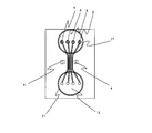
- a flow path pattern through which the sample liquid flows and a light reflecting surface 4 for guiding the light generated in the flow path to a specific surface of the flow cell are formed.
- a total reflection surface is formed in the flow cell by utilizing the interface between the flow cell base material and the gas.
- the refractive index of the flow cell base material is Nf
- the front and back planes of the flat plate flow cell function as a total reflection surface. That is, among the signal light (scattered light and fluorescence) generated at the moment when the cells flowing through the flow path 5 pass through the irradiation region 1, the signal light 6 traveling sideways (in the plane of the flat plate) is within a range of ⁇ 45 degrees. In the inside, total reflection occurs on the front and back surfaces 4 of the flow cell. Therefore, it is efficient when detecting light emitted outside the end face.
- the side surface 4 also becomes a boundary between the resin and the gas, so that it can be a total reflection surface.
- the flow cell can efficiently detect the side signal light in the direction of the end face by efficiently guiding the light generated from the flow path to the end face by the upper, lower, left and right total reflection surfaces.
- the flow cell shown in FIG. 3 and FIG. 4 forms side surfaces of the signal light in the substrate or at the end face to form a total reflection surface, which is used to reflect the signal light in the direction of the front or back side. This is a structure for detecting the direction signal light.
- the total reflection is formed in the flow cell, thereby enabling the detection of the side signal light in the flat flow cell.
- the following means is adopted.
- a flexible light guide tube 17 is installed in the vicinity of the end face, and the light is guided to the photodetector 2.
- the photodetectors can be freely arranged, and even if the positional relationship between the flow cell and the detection optical system is not strict, it can be guided to the photodetector with high efficiency if it enters the end face of the light guide.
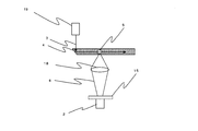
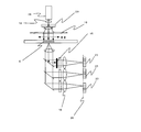
- the irradiation light 3 irradiates the flow path 5 almost perpendicularly to the flow cell substrate, and the detection of scattered light and fluorescence generated from the sample particles is transmitted through the flow cell substrate to the substrate surface.
- an optical system that detects the wavelength of the emitted signal light using a dichroic mirror 14 and a bandpass filter 15 and a light guide 17 installed outside the flow cell using the total reflection surface 4 formed in the flow cell.
- a detection system that separates the wavelength through the bandpass filter 15 and guides it to the detector 2 for detection, a forward scattered light signal, a side scattered light signal having the same wavelength as the incident light, and a wavelength different from that of the incident light for each fine particle. It becomes possible to detect the fluorescence.
- the whole liquid feeding system can be exchanged together with the flow cell, and means for enabling detection of forward scattered light and side scattered light is as follows.
- Irradiate with sample liquid containing biological particles flowing in the flow channel in the flow cell detect scattered light and fluorescence generated from the particles with a photodetector, and identify the particles based on their signal intensity
- an upstream reservoir and a downstream reservoir connected to the upper end and lower end of the flow cell flow path are formed on the flow cell substrate, respectively, and air is passed between both reservoirs via air.
- the flow cell has a function of controlling the flow rate of the sample liquid flowing from the upstream reservoir to the downstream reservoir by applying pressure, and the flow cell has a structure in which a flow path is formed inside the flat plate substrate, as shown in FIG.
- the light on the side that is, in the in-plane direction of the substrate, is guided to the light guide installed outside the flow cell using the total reflection surface formed on the substrate.
- the biological particle analysis separation apparatus characterized by detecting the scattered light enters the substrate surface passes through the flow cell substrate from the channel.
- the entire flow system is embedded in the flow cell, and the flow cell that enables side scattered light with reduced autofluorescence is as follows.
- the flow cell for flowing a sample solution containing particles
- the flow cell has a structure in which a flow path is formed in a transparent substrate, and reservoirs are formed on the upstream side and the downstream side of the flow path, respectively.
- the sample solution introduction channel 1 connected to the sample reservoir, a pair of sheath solution introduction channels 2 arranged on both sides thereof and connected to the sheath solution reservoir, and these channels merge to form the sample solution
- a flow cell that has a structure in which scattered light is guided to a specific area.
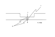
- the side scattered light can be detected. That is, as shown in FIG. 5, when the flow path 5 is irradiated from the in-plane direction using the total reflection surface 4 formed inside the flow cell, the detection optical system below the substrate of the flow cell has a side signal light. It is because it detects.
- This irradiation system is also effective as a means for measuring multiple specimens described below.
- FIG. 8 Means for Realizing a Multi-Sample Flow Cytometer
- the method shown in FIG. 5 is applied to a multi-channel flow cell.
- an imaging lens is used as a detection optical system to connect the flow path image to the imaging surface 26.
- An image is taken and an array detector 23 is placed on the surface.
- the size of the detection surface is assumed to be smaller than the width of each flow path on the imaging surface.
- the light absorbing member 25 is for preventing the strong reflected light of the irradiation beam from returning to the flow path.
- FIG. 9 shows a method of irradiating a plurality of channels by irradiating irradiation light from the end face without using the total reflection surface in the flow cell.
- FIG. 10 is a top view of the flow cell of FIG. 8 in which a plurality of flow paths and total reflection surfaces are formed.
- FIG. 11 shows a method of simultaneously detecting a plurality of channels by scanning an irradiation laser beam at a high speed across a plurality of channels.
- a deflector using an optical acoustic element is used.
- an array detector is installed on the imaging plane as an imaging system as a detection optical system in the same manner as described above.
- the frequency of the deflector using the optical acoustic element is 10 MHz or more, and the response frequency of the photodetector is about several tens of kHz.
- the laser beam scanning period is smaller than the time response frequency of the detector, if the fine particle is irradiated multiple times by beam scanning while passing through the irradiation area, the signal pulse will be generated multiple times, and the signal processing There is a disadvantage that it becomes complicated.
- one signal pulse is generated for one particle.
- FIG. 12 shows a method of measuring a plurality of flow paths in units of flow paths by step-and-repeat with a flow cell or a laser beam. Since the detection optical system in this case does not need to distinguish the flow paths, the detector does not need to be an array detector.
- FIG. 13 shows the structure of a flow cell applied to the apparatus shown in FIG. In this case, the sheath liquid reservoir 9 is installed, and the sheath liquid is joined to each sample channel from the left and right in order to restrict the flow of the sample liquid to be smaller than the irradiation light beam size.
- the laser beam is sequentially stayed at a central position of each flow path formed at equal intervals, and then moved to the next flow path. As described above, the fine particles of the plurality of sample solutions are sequentially analyzed.
- each flow path is connected to a common waste liquid reservoir. This waste liquid reservoir is formed on the flow cell.
- the following means is a flow cell in which microcapillaries are integrated in an array, and is combined with the irradiation system using the laser beam high-speed scanning described above.
- the advantage of this means is that the sample is drawn directly from the sample pretreatment multi-hole plate and automatically and sequentially measured.
- a jig 35 that adjusts the interval between capillaries is used for the array interval of the multi-hole plate sample solution. After the completion of one measurement, the stage of the multi-hole plate stage is automatically moved in the height direction and the horizontal direction, and the next sample liquid array is sucked up and the measurement is executed.
- FIG. 15 is a cross-sectional view of a flow cell using a capillary array.
- the flow cell has a sample solution introduction channel 45 connected to the upstream sample solution reservoir 8, a pair of sheath solution introduction channels 46 connected to the sheath solution reservoir 9, and these flow together to form the sample solution.
- a flow channel 5 through which the sheath liquid flows on both sides of the surface, and a particle separation region 39 downstream from the laser irradiation region 1, where a flow channel 47 is connected to the side surface of the flow channel 5.
- the flow paths 47 are connected correspondingly in one set, and a pulse pump is connected to each flow path 47. Up to two types of particles to be separated are discriminated by optical signals generated when the particles pass through the laser irradiation region 1, and if the particles are to be separated, the fine particles flowing in the flow path 5 as shown in FIG. On the other hand, by applying a pulse flow from a pulse pump corresponding to two types of separation in advance through the flow channel 47, the flow position of the particles in the flow channel 5 is shifted, and the flow channel 5 is based on the shift. Are separated into particles when the two pulse pumps are OFF, particles when the right pulse pump is ON, and particles when the left pulse pump is ON.
- the principle of this separation is that the most downstream of the flow channel 1 forms a flow channel that branches into three in contrast to the confluence portion upstream of the flow channel 1, so that the sample liquid and the sheath liquid are divided into three branch flow paths.
- particles usually flow through the central flow path 44, but the particles shifted by the pulse flow flow into the flow path 42 in the case of a flow pushed by the pulse, In this case, it flows into the flow path 43.
- a piezo pump is suitable as the pulse pump. The amount of one pulse flow can be controlled by the voltage applied to the piezo.
- the structure of the flow cell for the above cell separation method must satisfy the following requirements.
- a sample solution introduction channel 45 connected to the sample solution reservoir 8 and a pair of sheath solution introduction channels 46 connected to the sheath solution reservoir 9 are joined together, and the sheath solution flows on both sides of the sample solution.
- There is a flow channel 1 and a flow channel 47 is connected to the side surface of the flow channel 1 on the downstream side of the laser irradiation region, and the most downstream side of the flow channel 1 has three in contrast to the merging portion upstream of the flow channel 1.
- a branching flow path is formed.
- the flow path 47 has a port for connecting to the outside of the flow cell.
- FIG. 19 shows a means with only one channel 47 and pulse pump, but in this case, only one kind of particles can be separated. Since the pulse flow by the pulse pump in FIG.
- a sorting supply liquid tank is connected to the pulse pump.
- a sorting recovery liquid tank is required.
- the amount drawn by the pulse flow is too large, it will be drawn to the separated cells, and the pulse flow rate must be adjusted to prevent this. From the viewpoint of a biohazard, when separating infected cells such as viruses, it is desirable that the sample liquid is confined in the flow cell, so that the direction of pushing out the pulse flow is desirable.
- the principle of fine particle separation described above can be said to be a method in which the flow of fine particles is shifted by a pulse flow and separated by a downstream branch channel.
- FIG. 20 is a cross-sectional view of the flow cell as viewed from the side.
- the upstream side of the region 39 is a cross section at the center of the flow cell, but the downstream side of the region 39 is a cross section along the flow path 47.
- the flow path 47 is connected to a reservoir 48 for separated cells, and the reservoir is connected to the pulse pump 41 in a sealed system via air. As a result, the liquid does not come out of the flow cell.
- This method can be said to be a method for realizing the method described in Patent Document 13 on a disposable flow cell. This is because the cell recovery liquid separated from the sample liquid, the sheath liquid, and the waste liquid is all on the flow cell. This established a biohazardous cell separation method.
- This method is intended to separate very low density target particles from high density contaminant particles.
- a magnetic separation is used as the first-stage particle separation, and the above-described separation method using the pulse flow will be described in the second stage.
- the flow cell for flowing a sample solution containing particles
- the flow cell has a structure in which a flow path is formed in a transparent substrate, and reservoirs are formed on the upstream side and the downstream side of the flow path, respectively.
- the sample solution introduction channel connected to the sample reservoir, the sheath solution introduction channel 2 connected to the sheath fluid reservoir, and these channels merge to restrict the sample solution flow to a laminar flow state.
- An electromagnet is installed in the vicinity of the flow path 3, and a magnetic field is generated throughout the flow of the sample liquid.
- At least a magnetic particle having a membrane protein antibody 1 attached to the surface to be labeled with the target cell, and a fluorescent antibody 2 with another membrane protein to be labeled with the target cell are further contained.
- Target cells for separation are attracted to an area where the spatial density of magnetic field lines is high. By this force, the target particles are shifted from the flow of the sample liquid toward the flow of the sheath liquid. Using this shift, the first separation flow path 50 on the downstream side is separated.
- the pulse pump 41 acts on the target cells through the suction pulse second separation flow path 52 and collects them in the separated cell collection reservoir 54. As described above, the cell separation accuracy is improved by combining different antibody labels with different separation methods.
- thermoresponsive magnetic nanoparticles of Patent Document 16 are particles that can control aggregation and dispersion in a solution depending on temperature. When magnetic particles become 0.1 micrometer or less, the magnetic moment per particle decreases, and the influence of external force on the particle due to Brownian motion increases, so that a strong gradient magnetic field is required for magnetic separation. However, since the aggregated magnetic particles have large magnetic moments, they can be separated even with a weak gradient magnetic field.
- Thermoresponsive magnetic nanoparticles are composed of magnetic particles and a thermoresponsive polymer, and the temperature range at the boundary between aggregation and dispersion varies depending on the properties of the thermoresponsive polymer. Therefore, in the present invention, a plurality of magnetically responsive magnetic nanoparticles having different aggregation temperature ranges are used, and magnetic separation is sequentially performed at different aggregation temperatures using particles obtained by binding different antibodies to each other.
- a multi-stage separation method is proposed. For example, a method for separating only cells containing both M antigen and N antigen from a group of cells containing cells containing both M antigen and N antigen, cells containing either one, and cells containing neither is as follows. To do.
- thermoresponsive magnetic nanoparticles are A particles and B particles, and only particle A aggregates at temperature A and only particle B aggregates at temperature B.
- the particle A bound to the M antibody is referred to as M antibody-bound particle A
- the particle B bound to the N antibody is referred to as N antibody-bound particle B.
- M antibody particles A and N antibody particles B are mixed with the cell solution before separation, and bound by antigen-antibody reaction.
- the cells bound to the particles A are separated by being kept at the temperature A and exposed to a gradient magnetic field. That is, cells having M antigen are isolated.
- the liquid containing only the separated cells is kept at the temperature B and separated by a gradient magnetic field to further separate cells having N antigen.
- the apparatus is provided with a mechanism for controlling the temperature of the flow cell.
- This temperature control mechanism has a structure in which a part for installing the flow cell is heated and cooled by a Peltier element.
- a flow cytometer or a cell sorter is realized in which the entire liquid feeding system including the sheath liquid reservoir can be exchanged together with the flow cell chip. Furthermore, a flow cytometer that performs automatic and parallel measurement of multiple specimens is realized. Furthermore, a cell separation method using a plurality of antigen-antibody reactions is realized.
- tip which has a function which guide
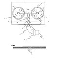
- 1 illustrates a flow cell chip having a function of guiding signal light generated in a flow path to an external detector using the front and back surfaces and side surfaces of grooves as reflection surfaces according to the present invention. Illustrated is a planar flow cell having a function of forming a reflection surface on the flow cell in the vicinity of the side surface of the flow path and reflecting the signal light generated in the flow path in a direction perpendicular to the flow cell plane to guide it to an external detector. It is a thing.
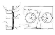
- FIG. 2 illustrates an optical system of an apparatus of the present invention that simultaneously detects side scattered light and forward scattered light using a flow cell chip with a built-in reflection.
- 2 illustrates an optical system that uses a reflection surface in a chip of the present invention for reflection of irradiation light.
- produces from the flow cell itself is illustrated.
- 1 illustrates the structure of a flow cell chip incorporating a reservoir and a reflective surface according to the present invention. Two types of reflecting surfaces are shown.
- FIG. 2 illustrates a method of irradiating a multi-flow path from a side surface at the same time by reflecting with a reflecting surface formed in a chip of the present invention.
- FIG. 2 is a diagram illustrating a method of simultaneously irradiating a multi-flow path from a side surface using a reflective surface installed outside a chip according to the present invention.
- FIG. 9 is a plan view of the flow cell shown in FIG. 8 according to the present invention.
- the present invention illustrates a method of scanning a laser beam at a high speed using a deflector, and simultaneously irradiating a multi-channel to measure each channel separately.
- tip of this invention is moved in order by step and repeat, and the method of measuring a multi flow path one after another is shown in figure.
- FIG. 2 illustrates a multi-sample flow cell of the present invention in which a plurality of sample liquid reservoirs, a common sheath liquid reservoir, and multi-channels are formed.
- FIG. 2 is a diagram illustrating a method of dealing with multiple specimens by scanning a laser beam using a flow cell as a capillary array according to the present invention.
- FIG. 15 is a cross-sectional view of the capillary of the capillary array of FIG. 1 is a diagram illustrating a first example of a flow cell for separating fine particles according to the present invention.
- FIG. 17 illustrates a fine particle separation method using the flow cell chip of FIG. 16. It is the photograph which observed the mode of FIG. 17 in the microchannel.
- FIG. 16 illustrates a fine particle separation method using the flow cell chip of FIG. 16. It is the photograph which observed the mode of FIG. 17 in the microchannel.
- FIG. 17 illustrates an example in which one pump is used in the fine particle separation method of FIG. 16.
- 2 illustrates a second example of a flow cell for separating fine particles according to the present invention.
- FIG. 21 illustrates a fine particle separation method using the flow cell of FIG. 20. It is sectional drawing of the flow cell of FIG. 1 illustrates an example of a flow cell chip for multistage separation of fine particles according to the present invention.
- FIG. 1 is a schematic diagram illustrating the simplest flow cell structure of the present invention.
- the material of the flow cell is an acrylic transparent resin.
- a concave flow path pattern is formed on the back side of the substrate by injection molding, and a flow path is formed by attaching a sheet having a thickness of about 100 ⁇ m thereon.
- the channel cross section is typically 80 micrometers wide and 25 to 50 micrometers deep.
- Reference numeral 1 denotes an irradiation region, which corresponds to a region in which laser light, which is irradiation light, irradiates fine particles flowing in the flow channel of the flow cell.
- the sample solution 10 is filled in the sample solution reservoir 8.
- the reservoir 8 is connected to the sample liquid channel 45.
- the sheath liquid 13 for narrowing and flowing the sample liquid is stored in the sheath liquid reservoir 9, and the reservoir 9 is connected to the sheath liquid channel 46.
- the sheath liquid channel 46 joins the sample liquid channel 45 from both sides and flows into the single channel 5.
- the reservoir 9 is higher than the reservoir 8, and the reservoir 9 has a structure in which pressure is applied from outside through air. This air pressure is simultaneously applied to the sample liquid 10 and the sheath liquid 13. This pressure value ranges from 2 kilopascals to 20 kilopascals. With this pressure, the sample liquid and the sheath liquid flow in the downstream side and merge in the flow path 5, and the sample liquid is narrowed down to a width of about 10 micrometers or less.
- the irradiation light the light of a semiconductor laser light source having a wavelength of 473 nm and an output of 10 mW is narrowed down to a beam diameter of about 60 micrometers, and is vertically centered on the flow path 5 in the region 1 with respect to the substrate of the flow cell. Irradiate.
- the signal light 6 emitted to the side repeats total reflection on the front and back surfaces 4 of the flow cell substrate, and reaches the end surface with high efficiency.
- the signal light emitted outside from the end face is detected by selecting the wavelength with the band-pass filter 15 on the photodetector with a light guide installed in the vicinity.
- the signal is a pulse signal, and in addition to the pulse height, the pulse area and the like are recorded for each particle.
- the present invention is such that the side signal light is detected using the total reflection inside the flow cell, and FIG.
- 1 is the simplest example of this content.
- one detector is used, but scattered light and fluorescence can be detected by using a plurality of wavelength separations.
- a semiconductor laser having another wavelength for example, 640 nm, can be irradiated simultaneously as a light source, and fluorescence signals excited at this wavelength can be detected separately.
- the reason why the light guide is installed in the vicinity and led to the light detector is that it is a detection optical system that is not easily affected by a slight displacement when the flow cell is replaced.
- a total reflection surface 4 is formed perpendicularly to the substrate plane from the vicinity of the flow channel side surface to the end surface, and the signal light 6 generated in the flow channel is generated.
- FIG. 3 shows a method of detecting lateral signal light generated from the flow path using a total reflection surface formed in the flow cell with a detector installed on the surface instead of the end surface direction.
- This figure shows an example of reflection on the front surface, but the same applies to the direction of the back surface.
- two types of positions on the substrate and at the substrate edge are shown as the positions of the total reflection surfaces.
- a total reflection surface is formed by the boundary between the resin and the atmosphere.
- a total reflection surface is formed by the boundary between the resin and the atmosphere.
- a total reflection surface since it can be formed in the vicinity of the side surface of the flow path, there is an advantage that it can be detected before the signal light on the side spreads greatly.
- a total reflection surface having an end surface as an inclined surface there is a demerit of moving away from the flow path, but there is a great advantage that manufacturing quality control in forming the inclined surface is easy.
- FIG. 4 shows an example of an optical system that enables detection of side scattered light and fluorescence in addition to forward scattered light as signal light using a flat plate flow cell.
- the light source is a 473 nm semiconductor laser.
- Side scattered light is detected through a light guide and a bandpass filter that transmits only an irradiation wavelength of 473 nm using the total reflection surface of the end face of the flow cell.
- the forward scattered light is detected by converting the signal light transmitted through the bottom surface of the flow cell into parallel light with a lens, reflecting it at 473 nm, and reflecting it with a dichroic mirror 14-1 that transmits light on the longer wavelength side.
- the direct transmitted light is cut by the light shielding plate 16 and then detected by a photodetector such as a photodiode through a bandpass filter that transmits only the irradiation wavelength of 473 nm.
- the fluorescence is detected by combining the dichroic mirror 14-2 and the bandpass filter 15-2 from the signal light transmitted through the dichroic mirror 14-1 out of the signal light transmitted through the bottom surface of the flow cell in the same manner as the forward scattered light.
- the fluorescence detection wavelength is selected by the bind pass filter 15-3 and detected by the photomultiplier tube.
- FIG. 7 is a schematic view of the flow cell of FIG. 4 as viewed from above.
- the reflective surface 4 is formed on the end surface of the substrate.
- the flow rate of the sample solution is controlled by the atmospheric pressure inside the upstream reservoir 9.
- FIG. 5 shows that when the total reflection surface formed in the flow cell substrate is used as irradiation light and the flow channel 5 is irradiated from the in-plane direction of the flow cell substrate, the light transmitted to the bottom surface of the flow cell becomes signal light to the side. .
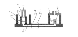
- FIG. 6 shows a method of reducing the fluorescence emitted from the resin flow cell itself.
- Acrylic which is a transparent resin, has slight light absorption at a wavelength of 400 nm or more. Therefore, when a strong laser beam of 473 nm is irradiated, fluorescence is generated from the entire irradiation region of the acrylic. In order to reduce the fluorescence intensity, the irradiation region through which the laser passes is made thinner than the surrounding area. This is a method for overcoming the two drawbacks that the flow cell is easily deformed when the entire periphery is thinned, and the fluorescence intensity from the flow cell is increased when the thickness is thickened.
- This technique can reduce background noise light in side signal light detection, particularly fluorescence detection, by combining with a technique for detecting side signal light by forming a total reflection surface in the flow cell.
- the total reflection surface formed in the flow cell substrate is used as irradiation light, and the flow channel 5 is irradiated from the direction in the flow cell substrate surface.
- a plurality of flow paths are formed.
- FIG. 10 shows the flow cell as viewed from above.
- the reservoir 27 on the upstream side is a pressurized space for applying a common air pressure to the plurality of sample solution reservoirs 8 without entering the liquid.
- Channels connected to the plurality of sample solution reservoirs 8 on a one-to-one basis are formed in an array in the substrate at equal intervals.
- the channel width is 80 micrometers, and the channel spacing is also 80 micrometers.
- the irradiation laser light is irradiated so as to penetrate a plurality of flow paths.
- the directly transmitted light of the irradiated light is reflected by the other total reflection surface in a direction perpendicular to the substrate surface and absorbed by the light absorbing member. If there is no reflection surface, the transmitted light of the irradiated light is irradiated to the end surface, and scattered light that becomes strong noise is generated.
- the reason why the light absorbing member absorbs the light is that when the light returns to the flow path and returns, the detection signal waveform is affected.
- the detection optical system employs a system in which an array photodetector is disposed on the imaging plane of the flow path in order to distinguish and detect individual flow paths.
- FIG. 9 shows a case where an external mirror is used without using total reflection inside the flow cell.
- the multiple flow paths are parallel to each other. This is because the diffracted light generated from the flow path interface is concentrated in a straight line, so that it can be easily removed by the band-shaped spatial filter 16. This is a method for preventing deterioration in detection sensitivity of scattered light signals.
- the embodiment shown in FIG. 11 is a method of measuring a plurality of sample liquids flowing through a plurality of flow paths at a time by scanning an irradiation laser beam at a high speed.
- the laser light source collimates a 473 nm semiconductor laser with a diameter of 1 mm, and scans the direction of the laser light at high speed using a deflector 29 of an AO modulation element.
- the lens 18 at the rear stage of the deflector the beam whose direction has been changed is made parallel, and the scanning of the change in the angle of the direction is converted into the scanning of translation.
- the scanning frequency by this deflector is about 40 MHz, and the response frequency of the signal processing system of the photodetector is set to about 20 kHz, so the scanning is 1000 times faster, so the irradiation system viewed from the detection system has a scanning width. Recognized as an extended line beam. In this case, it is important that the plurality of flow paths are parallel to each other. The reason for this is that the diffracted light from the channel wall surface is distributed in the direction perpendicular to the channel wall surface. This is because it can be removed by the light shielding plate.
- This light shielding plate is a spatial filter 16 used for cutting the transmitted light of the irradiation light in the forward scattered light detection optical system.
- the detection optical system installs an array detector 23 on the imaging surface 26 of the flow path as an imaging optical system in order to distinguish and detect a plurality of flow paths.
- the flow cell of FIG. 11 does not require a sheath flow, and is the same as FIG. 8 and FIG.
- the embodiment shown in FIG. 12 is not a method of measuring a plurality of flow paths simultaneously in parallel but a method of measuring sequentially.
- the measurement time is longer than the simultaneous and parallel measurement, but it is not necessary to distinguish the flow path as the detection optical system, so the imaging optical system and the array detector are not required as in FIG. .
- a method of sequentially measuring a plurality of flow paths both a method of moving the flow cell by step and repeat and a method of scanning the irradiation laser light by step and repeat can be applied.
- Fig. 13 shows a flow cell structure suitable for the step-and-repeat method.
- the irradiation laser light in this case is the same as the case of FIG. 1 and has a beam size for measurement of only a single flow path. Restricted to The region in which the laser light is moved is region 1. Since it is a step-and-repeat system, all the channels have a width of 80 micrometers and the intervals are uniform at 80 micrometers.
- a pair of sheath liquid introduction ports 32 corresponding to the respective sample liquid streams are supplied from a common sheath liquid reservoir 9 to each sample stream.
- a plurality of sample liquids flow all at once by pressurizing the reservoir 9, but the sample flow rate and measurement time are adjusted by pressure so that the measurement of each sample is completed before the sample liquid disappears from the sample liquid reservoir.
- 100 microliters of sample liquid continues to flow for 30 minutes or more under the pressurized condition of the reservoir 9 having an air pressure of 20 kilopascals. Since the number of sample liquid reservoirs is 8, the measurement time per sample is 1 minute, and the movement between channels is 2 seconds, the measurement of 8 samples is completed within 10 minutes.
- the waste liquid is stored in the waste liquid reservoir 21 through the recovery port 33 connected to each flow path.
- the waste liquid reservoir 21 is at atmospheric pressure.
- FIG. 14 is not an example of flow cytometry in which the entire liquid delivery system is formed on the flow cell.
- this is an example of carrying out automatic measurement of a large number of specimens, which is a drawback when using a disposable flow cell, and further described as an example of the present invention because it is a method using the laser beam high-speed scanning of the present invention.
- a flow cell is used in which microcapillaries are fixed in an array, and an irradiation laser beam is scanned at a high speed with a length that is equal to or greater than the width of the capillary array.
- the laser light source and the detection optical system use an imaging optical system and an array detector to distinguish individual capillaries.
- the capillaries are made of quartz, the inner diameter is 75 micrometers, and the outer diameter is 150 micrometers.
- a flow cell is formed by filling eight capillaries with a refractive index matching liquid having a refractive index of 1.42 and sandwiching them between two quartz plates. This reduces the intensity of reflected light and diffracted light generated when the capillary surface is irradiated with laser light.
- a 96-well plate is used for pretreatment of multiple specimens. This is because the sample holes are arranged in an 8x12 matrix, so that the 8 capillaries are aligned with the 8 rows of the 96-well plate by the adjustment jig 35, and the plate moves up and down each time one row is measured. If the movement in the row direction and the sample liquid suction measurement are repeated 12 times, 96 types of sample measurement are completed.
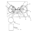
- FIG. 16 illustrates a first example of the fine particle separation flow cell of the present invention.
- the material of the flow cell is an acrylic transparent resin.
- a concave flow path pattern is formed on the back side of the substrate by injection molding, and a sheet having a thickness of about 100 ⁇ m is pasted thereon.
- a flow path is formed.
- the flow cell structure of FIG. 16 is based on the structure of FIG. 1 and has a flow path pattern in which a sorting flow path 47 is connected to the flow path 5 from both sides, and each flow path 47 has a pulse pump 41 outside the flow cell. Are connected via a pipe.
- the channel 5 has a channel width of 80 micrometers and a depth of 25 micrometers.
- the channel depth of the channel 47 is 25 micrometers, which is the same, but the channel width is 25 micrometers, the same as the depth. This is because the value of the ratio of the groove width to the depth is 1 in the present practical working limit when processing a mold for injection molding.
- the width of the flow path 47 must be 50 micrometers.
- the pulse pump operates by the expansion and contraction motion of the piezo element.
- the piezo pump has a time response up to 100 Hz and a pulse pressure of about 0.9 M Pascal. Adjust the flow rate to 0.5 nanoliters per pulse.
- the spatial resolution of cell separation by one pulse is determined by dividing the flow rate of one pulse by the cross-sectional area of the channel and the flow velocity.
- the speed is 200 mm / sec. 125 micrometer.
- the piezo element is strong against compressive stress, but easily breaks against tensile stress. Therefore, only the displacement due to the force generated in the direction in which the compressive stress is applied can be used. Therefore, it was necessary to make one piezo pump correspond to the unidirectional pulse flow generation. Since the direction of the pulse flow was pushed out, a sorting supply tank was connected to the piezo pump. This tank contains a PBS buffer solution, and must be a buffer solution that does not damage cells even if a pulse flow is mixed with cells flowing through the flow path 5.
- the timing for generating the pulse flow of the piezo pump can be set by a delay time after detection of scattered light and fluorescence signals generated at the moment when the fine particles pass through the measurement region 1.
- This delay time is a time until the particles reach the separation region 39 from the detection region 1. Therefore, this delay time is set depending on the speed of the particles.
- Based on the distribution of signal intensity of scattered light and fluorescence it is determined in real time whether or not it is a target particle. If it is a target particle, only the piezo pump corresponding to one of the two types of targets is turned ON.
- This process sends a trigger signal to the piezo pump driver circuit of the corresponding piezo pump after a certain delay time from signal detection based on the signal processing result of the signal light, and the driver circuit piezo pumps the voltage signal for one pulse. Turn on by entering.
- the position of the target particle that receives the pulse flow shifts.
- the central branch channel 44 is a channel through which particles flow when the pulp pump is in the OFF state, and is shifted by the pulse flow when the pulse pump is in the ON state.
- FIG. 18 is a photograph observing the moment when the flow is shifted by the pulse flow. The flow lines of the sample liquid are visualized by putting ink only in the sample liquid.
- the piezo pump When the piezo pump is OFF, the sample liquid is sandwiched between the sheath liquid and flows through the center of the flow path. However, when a pulse flow is applied from the flow path on the lower side, the flow of the sample liquid is shifted. I understand.
- the two types of target particles are separated by the flow cell connected so that the two sorting channels 47 face the channel 5, but the channels 47 are separated as shown in FIG. It is possible to separate only one type of target particle as a book.
- the flow cell of FIG. 20 connects a pulse flow that draws into the flow path 47 to the flow path 47 at the moment when the particles identified as the particles to be separated in the measurement area 1 pass through the particle separation area 39.
- the particles taken in and separated by (1) are stored in a reservoir 48 for separated particles.
- the state of this separation is shown in FIG. FIG. 22 is a cross-sectional view of this flow cell structure.
- the separated particle reservoir 48 and the pulse pump are connected via air. As a result, the separated particles are stored in the separated particle reservoir 48.
- Fig. 20 shows only one pulse pump installed, but as in Fig. 16, two downstream flow channels are used, and two types of particles are installed by installing a pulse pump via reservoirs on both sides. Separation was also possible. The process from the signal processing to the operation of the pulse pump in this case is the same as that of the embodiment of FIG.
- FIG. 23 schematically shows a structure in which separation using a magnetic field is performed in the first stage and separation using a pulse flow is performed in one flow cell in the subsequent stage.
- the sample solution consists of a sample containing various cells, magnetic particles coated with an antibody that binds to the membrane protein of the target cell for separation, and a fluorescent antibody that binds to another membrane protein of the target cell (fluorescent reagent such as Cy5) And a mixture of a nuclear stain (such as SYTO9) to distinguish cells and biological membrane fragments.
- a sample solution reservoir 8 is formed in the sheath solution reservoir 9 on the upstream side.
- one sheath liquid channel 46 is sufficient in this embodiment. This is because the sample solution 10 need only be concentrated at the end of the flow path in the flow path 5 and does not need to be concentrated at the center as shown in FIG. As a result, in the particle separation region 39-1, magnetic particles having a magnetic moment are attracted to a region where the density of the magnetic force lines is high by the magnetic force lines diverging by the magnet. The strength of the magnetic field is adjusted by the current of the electromagnet, and the flow rate of the sample is adjusted by the pressure so that a sufficient shift amount is obtained while the speed of migration of the magnetic particles by the magnetic field passes through the particle separation region 39-1. .
- the fine particle measurement region 1 to be irradiated with the laser was set in the flow path 50.
- the laser light source two types of semiconductor lasers of 473 nm and 640 nm were used. This is because the 473 nm laser light excites SYTO9, and the 640 nm laser light excites Cy5.
- the two types of laser light were uniformly irradiated to the channel 50 with a beam size of 160 ⁇ m wider than the channel width of the channel 50.
- Particles emitting fluorescent antibody fluorescence and nuclear stain fluorescence in this region were detected by wavelength separation with a dichroic mirror and a bandpass filter in the same manner as the detection optical system shown in FIG.
- the separated cell reservoir 54 was stored by a pulse flow drawn from the connected channel 47.
- the pulse pump is connected to the reservoir 54 through air so that the separated cell fluid does not flow out to the pump side.
- This countermeasure is the same as the biohazard countermeasure described in FIG. As described above, magnetic separation and separation using a pulse flow by a fluorescence signal were realized on the flow cell.
- thermoresponsive magnetic particles Three types of thermoresponsive magnetic particles were used: Therma-MAX LSA-Streptavidin and Therma-MAX UB Biotin and Therma-MAX LB Biotin manufactured by Magnabeat Co., Ltd. These particles have an average particle size of about 100 nm.
- Therma-MAX LSA Streptavidin has the property of aggregating at 30 ° C or higher and dispersing at 20 ° C or lower. Streptavidin is bound to the particle surface, and thermoresponsive magnetic particles can be coated with various antibodies bound to biodin. It is.
- Therma-MAX UB Biotin has a property of being dispersed at 10 ° C or higher and aggregating at 4 ° C or lower, biotin binding to the particle surface, and thermal response capable of coating various antibodies bound to avidin. Magnetic particles.
- Therma-MAX LB Biotin has the property of dispersing at 32 ° C or lower and aggregating at 42 ° C or higher. Biotin is bound to the surface of the particle and can be coated with various antibodies bound to avidin. It is.
- anti-EpiCAM a monoclonal antibody against a surface antigen (EpiCAM) specifically expressed in epithelial cells
- anti-CK a monoclonal antibody against cytokeratin
- anti-CD45 a monoclonal antibody against CD45
- the anti-CD45 particles are aggregated, and the cells adsorbed to the anti-CD45 particles are removed from the blood sample together with the particles. Thereafter, a gradient magnetic field is applied to the remaining liquid by bringing a magnet close to the anti-EpiCAM particles at 30 ° C. so that the cells adsorbed to the anti-EpiCAM particles are collected and suspended in a PBS buffer solution. It becomes cloudy.
- a gradient magnetic field By applying a gradient magnetic field by bringing a magnet close to the solution at a temperature of 4 ° C., the cells adsorbed to the anti-CK particles are collected and finally suspended in 100 uL of PBS buffer.
- this final suspension contains anti-EpiCAM particles and anti-CK particles, it is measured with a flow cytometer using the flow cell capable of collecting the sample solution shown in the present invention while maintaining both at 20 ° C. where both particles are dispersed. Then, the total number of cells is measured, and the cells after measurement are collected. According to JP 2007-178193 A, this cell is a floating cell contained in blood and corresponds to a cancer cell circulating in the blood that causes metastasis.
- Deflector 30 ... Mirror 31 ... Pressurizing space 32 ... Sheath liquid introduction port 33 ... Recovery port 34 ... Capillary 35 ... Spacing adjuster 36 ... Multi-hole plate sample container 37 ... Refractive index matching liquid 38 ... quartz plate 39 ... particle separation region 40 ... sorting supply liquid tank 41 ... pulse pump 2 ... reservoir A 43 ... Reservoir B 44 ... Reservoir C 45 ... Sample liquid channel 46 ... Sheath liquid channel 47 ... Pulse flow channel 48 ... Separation cell liquid 49 ... Electromagnet 50 ... First separation channel 52 ... Second separation channel 53 ... Waste fluid channel 54: Reservoir for isolated cells
Landscapes
- Health & Medical Sciences (AREA)
- Life Sciences & Earth Sciences (AREA)
- Chemical & Material Sciences (AREA)
- Engineering & Computer Science (AREA)
- Physics & Mathematics (AREA)
- Immunology (AREA)
- Biomedical Technology (AREA)
- Biochemistry (AREA)
- General Health & Medical Sciences (AREA)
- General Physics & Mathematics (AREA)
- Analytical Chemistry (AREA)
- Pathology (AREA)
- Hematology (AREA)
- Molecular Biology (AREA)
- Urology & Nephrology (AREA)
- Dispersion Chemistry (AREA)
- Food Science & Technology (AREA)
- Medicinal Chemistry (AREA)
- Biophysics (AREA)
- Optics & Photonics (AREA)
- Cell Biology (AREA)
- Tropical Medicine & Parasitology (AREA)
- Biotechnology (AREA)
- Microbiology (AREA)
- Zoology (AREA)
- Ecology (AREA)
- Virology (AREA)
- Investigating, Analyzing Materials By Fluorescence Or Luminescence (AREA)
- Optical Measuring Cells (AREA)
- Nuclear Medicine, Radiotherapy & Molecular Imaging (AREA)
Abstract
To overcome biohazard problems occurring in the existing flow cytometers and cell sorters.
A device for analyzing microparticles in a liquid comprising a means for placing a flow cell provided with a channel for flowing a liquid sample containing microparticles therethrough, a means for irradiating with light the liquid sample flowing through the channel of the flow cell, a light detector for detecting scattered light and/or fluorescence generated from the particles in the liquid sample, and a means for analyzing the particles based on the intensity of signals detected by the light detector, characterized in that: in the flow cell, the channel is formed in a flat substrate; a reflecting surface is formed in the side face of the channel; the reflecting surface guides a light traveling in the in-plane direction of the substrate, from among lights generated in the channel of the flow cell, to a specific area of the flow cell surface; and the light detector detects the light coming out of the specific area.
Description
本発明は、フローサイトメーターなどの生体粒子の解析機能またはセルソーターなどの分離機能を有する装置、それを用いる新規な機能を実現する測定方法、および使い捨てフローセルチップに関する。
The present invention relates to a device having an analysis function of a biological particle such as a flow cytometer or a separation function such as a cell sorter, a measurement method that realizes a new function using the device, and a disposable flow cell chip.
フローサイトメーターは、種々のタイプの細胞および生物学的流体を鑑別するために一般に用いられている。従来のフローサイトメーターは、通常、石英から作製され、それを通って個々に識別されるべき細胞の流れが流れるように流路が形成された光学的に透明なフローセルを備えている。この流路を通る細胞の流れは、この細胞の流れを同心的に取り囲むシース液体によって、流路の中央部に集中して流れる。この流路の中央部は、レーザービームで照射され、細胞がその照射領域を通過したときに、細胞の大きさ、形、屈折率に依存した光散乱が生じる。このレーザー光の波長は、蛍光色素で特異的に染色した細胞を蛍光で検出するために、蛍光色素の種類との組み合わせで決定される。このように、個々の細胞について散乱光のほかに蛍光を波長別に複数の光検出器で検出することによって、細胞を多角的に解析することが可能となっている。上記のフローサイトメーターの技術は特許文献1に記載されている。また平板状のフローセルについては特開平2003-302330(特許文献13)と米国特許第7105355号(特許文献14)に記載されている。フローサイトメーターの照射方式として流路内でレーザービームを走査することで正確な信号光強度を計測する方法が特許文献2,3,4に記載されている。
Flow cytometers are commonly used to differentiate between various types of cells and biological fluids. Conventional flow cytometers are typically equipped with an optically transparent flow cell made of quartz and having flow channels formed through which the flow of cells to be individually identified flows. The flow of cells through this flow path is concentrated in the center of the flow path by a sheath liquid that concentrically surrounds the flow of cells. The central portion of this flow path is irradiated with a laser beam, and when the cells pass through the irradiation region, light scattering depending on the size, shape, and refractive index of the cells occurs. The wavelength of the laser light is determined by the combination with the type of fluorescent dye in order to detect the cells specifically stained with the fluorescent dye with fluorescence. As described above, by detecting fluorescence in addition to scattered light for each cell with a plurality of photodetectors for each wavelength, it is possible to analyze the cells from various angles. The technique of the above flow cytometer is described in Patent Document 1. The flat flow cell is described in JP-A-2003-302330 (Patent Document 13) and US Pat. No. 7,105,355 (Patent Document 14). Patent Documents 2, 3 and 4 describe a method of measuring an accurate signal light intensity by scanning a laser beam in a flow path as an irradiation method of a flow cytometer.
次にセルソーティング方法の公知例について述べる。米国特許第3710933号(特許文献1)または米国特許第3826364号(特許文献5)に記述されている方法が現在一般的な製品に使用されている分離方法であって、液滴形成用ノズルから空気中に試料液を液滴として吐出し、分離対象の細胞を含む液滴は液滴単位で電場によって分離するという方法である。特開昭64-3541(特許文献6)は、フローセルを流れる試料液の周囲にシース流を流し、試料液に電場を加えることで帯電した粒子を試料流からシース流の法へシフトさせて分離計測する方法である。特開平1-170853(特許文献7)は、フローセルを流れる粒子に圧力パルスを与えて、フローセル内の定常的に流れている流路ではない流路に粒子を分離する方法が記載されている。国際公開番号WO98/10267(特許文献8)は、フローセル内に周囲をシース流でしぼって流した微粒子に場を与えて微粒子の流れをシフトさせて分離するという技術が公開されている。国際公開番号WO2004/101731(特許文献9)において、フローセル内の流路の両側に設置したゲル電極によって液体中で帯電している細胞を電場で分離する方法が公開されている。米国特許US6808075(特許文献10)において、粒子の流れに対して垂直にメニスカスを形成するバブルバルブにより圧力パルスを加えて流れをシフトさせて分離する方式が公開されている。WO2006/076195 (特許文献11)は、特許文献8と同様に圧力パルスを与えるが目的とする粒子を含む水滴単位で射出してコンテナに回収方法である。米国特許第4756427号(特許文献12)には、シース流で絞られた試料液の流れの中の粒子を計測しターゲットとなる粒子であると判断した場合に、パルス流で別流路に導入して分離する方法が記載されている。抗体をコーティングした磁気粒子を利用して、特定の細胞に磁気粒子を吸着させ勾配磁場で分離する方法が知られている(特許文献15)。温度によって凝集制御可能な熱応答性磁性ナノ粒子が公開されている(特許文献16)。熱応答性磁性ナノ粒子を利用して細胞を分離する方法が公開されている(非特許文献1)。
Next, a known example of the cell sorting method will be described. The method described in U.S. Pat. No. 3,710,933 (Patent Document 1) or U.S. Pat. No. 3,826,364 (Patent Document 5) is a separation method that is currently used in general products, from a droplet forming nozzle. This is a method in which a sample liquid is ejected as droplets into the air, and droplets containing cells to be separated are separated by an electric field in units of droplets. Japanese Patent Application Laid-Open No. 64-3541 (Patent Document 6) separates charged particles by shifting the sheath flow from the sample flow to the sheath flow method by flowing a sheath flow around the sample solution flowing through the flow cell and applying an electric field to the sample solution. It is a method of measuring. Japanese Patent Laid-Open No. 1-170853 (Patent Document 7) describes a method of applying pressure pulses to particles flowing in a flow cell and separating the particles into a flow path that is not a steady flow path in the flow cell. International Publication No. WO98 / 10267 (Patent Document 8) discloses a technique in which a flow is applied to fine particles that have been flown by a sheath flow around the flow cell, and the flow of fine particles is separated. International Publication No. WO2004 / 101731 (Patent Document 9) discloses a method of separating cells charged in a liquid with an electric field by gel electrodes installed on both sides of a flow path in a flow cell. In US Pat. No. 6,808,075 (Patent Document 10), a system is disclosed in which a pressure pulse is applied by a bubble valve that forms a meniscus perpendicular to the flow of particles to shift the flow and separate. WO2006 / 076195 (Patent Document 11) is a method of applying a pressure pulse as in Patent Document 8 but injecting it in units of water droplets containing the target particles and collecting it in a container. US Pat. No. 4,754,427 (Patent Document 12) introduces a pulse flow into a separate flow channel when particles in a sample liquid flow constricted by a sheath flow are measured and determined to be target particles. And the method of separation is described. A method of using magnetic particles coated with antibodies to adsorb magnetic particles to specific cells and separating them with a gradient magnetic field is known (Patent Document 15). Thermally responsive magnetic nanoparticles that can be controlled in aggregation by temperature have been disclosed (Patent Document 16). A method for separating cells using thermoresponsive magnetic nanoparticles is disclosed (Non-patent Document 1).
従来のフローサイトメーターおよびセルソーターは、バイオハザード上の課題が存在する。すなわち、測定サンプルへの外部異物の混入や測定サンプルの外部への拡散が生じる構造となっているからである。すなわち、試料液のリザーバーおよび送液パイプ、フローセルを含めた送液系は、簡単に取り替えることは不可能であり、従来のフローサイトメーターは、キャリーオーバーを防止するためには異なる試料の測定ごとに洗浄しなければならない。このことは、フローサイトメーターに粒子分離機能を追加した装置であるセルソーターについても同様である。その解決策の一つとして、フローセルを使い捨て可能とすることである。使い捨て可能とするためには、フローセルがスライドガラスのような平板状構造であると都合がよい。つまり、射出成形などで流路パターンの形成が容易かつ安価に量産できる構造であるためである。平板状のフローセルを用いる場合は、表面から垂直に照射レーザーを入射する方法が都合よい。しかしながら、平板の面内方向への散乱光つまり側方散乱光の検出に問題が存在する。通常のフローサイトメーターのフローセルはフローセルの断面が正四角であることが一般的であって、レーザーの照射方向と垂直方向の散乱光を計測することは問題がなく前方散乱光と同時に計測される。しかし、平板型のフローセルを用いた場合は、側方散乱光の方向にフローセル基板が存在するので、フローセルの平板構造自体が測定の障害となる。この課題を解決する方法として、特許文献14にフローセルの流路の側面に光ファイバーを設置し流路内で発生した光を光検出器まで導く方法が記載されている。しかし、この場合は光ファイバーがフローセルに接続しているために測定ごとのフローセル交換には適さないので、使い捨て用途のフローセルに適用することはできない。
Conventional flow cytometers and cell sorters have biohazard issues. That is, the structure is such that external foreign matter is mixed into the measurement sample and the measurement sample is diffused to the outside. In other words, the liquid supply system including the sample liquid reservoir, the liquid supply pipe, and the flow cell cannot be easily replaced. In order to prevent carryover, the conventional flow cytometer is different for each measurement of different samples. Must be washed. The same applies to the cell sorter which is an apparatus in which a particle separation function is added to the flow cytometer. One solution is to make the flow cell disposable. In order to be disposable, it is convenient that the flow cell has a flat plate structure such as a slide glass. In other words, this is because the flow path pattern can be easily and inexpensively mass-produced by injection molding or the like. When a flat flow cell is used, a method in which an irradiation laser is incident vertically from the surface is convenient. However, there is a problem in detecting scattered light in the in-plane direction of the flat plate, that is, side scattered light. The flow cell of a normal flow cytometer generally has a square cross section, and there is no problem in measuring the scattered light in the direction perpendicular to the laser irradiation direction and it is measured simultaneously with the forward scattered light. . However, when a flat type flow cell is used, the flow cell substrate exists in the direction of the side scattered light, so the flat structure of the flow cell itself becomes an obstacle to measurement. As a method for solving this problem, Patent Document 14 describes a method in which an optical fiber is installed on a side surface of a flow path of a flow cell and light generated in the flow path is guided to a photodetector. However, in this case, since the optical fiber is connected to the flow cell, it is not suitable for exchange of the flow cell for each measurement, and therefore cannot be applied to a flow cell for disposable use.
また、フローセルを安価に製造できなければ、使い捨てにすることは困難になる。安価に製造するためには、透明樹脂製であることが都合良い。しかしながら、樹脂は波長500nmより短波長領域ではわずかながら光吸収帯が存在し蛍光を発生するので、計測の背景ノイズとなる。つまり、使い捨てとして都合が良い透明樹脂製のフローセルの場合は、自家蛍光が計測の障害である。
Also, if the flow cell cannot be manufactured at a low cost, it will be difficult to make it disposable. In order to manufacture inexpensively, it is convenient that it is made of a transparent resin. However, since the resin has a slight light absorption band in the wavelength region shorter than the wavelength of 500 nm and generates fluorescence, it becomes a background noise of measurement. That is, in the case of a flow cell made of a transparent resin that is convenient as a disposable, autofluorescence is an obstacle to measurement.
次に、微粒子分離方法の課題について述べる。第一の課題としてバイオハザード対策上の問題がある。特許文献1または特許文献5に記述されているジェットノズルによる液滴と出方式は、バイオハザード対策上問題がある。つまりサンプルが病原性のウイルスや細菌に汚染された細胞の場合、非常に危険なものをエアロゾルとして大気中に拡散させてしまうというリスクを有している。第一の課題を解決する方式としては、エアロゾルを大気中に拡散せずフローセル内に閉じ込めたまま分離する方法が考えられる。このような方法として、次のいくつかの技術が公開されている。特許文献6はフローセルを流れる試料液の周囲にシース流を流し、試料液に電場を加えることで帯電した粒子を試料流からシース流の法へ電場でシフトさせて分離計測する方法である。特許文献7は、フローセルを流れる粒子に圧力パルスを与えて、フローセル内の定常的に流れている流路ではない流路に粒子を分離する方法であるが、分離した粒子がまたもとの流路に戻らないためのプロセスが面倒という課題が存在する。特許文献8は、フローセル内に周囲をシース流でしぼって流した微粒子に電場や磁場などの場を与えて微粒子の流れをシフトさせて分離するという技術である。この方法において場として電場を適用する場合は、上記特許文献6の内容に相当するが、特許文献9における方法と同じで電場を利用する方法は、電気分解による気泡発生を何らかの方法で防止したとしても、細胞の有する電荷は周囲の電解質中に含まれるイオンによってシールドされ、粒子に作用する力が低下するという問題が存在するので、電解質中での分離には実用的でない。特許文献10は、チップ内でのソーティングする技術である。一個の微粒子を分離するのにメニスカスの往復運動が必要であり、行きと帰りで逆方向の流れが生じるため、粒子が十分に遠ざかるのをまったのちにメニスカス位置を元に戻す必要があるという点で問題がある。特許文献11は、特許文献7と同様に圧力パルスを与えて目的とする細胞を含む領域を水滴単位で射出してコンテナに回収方法となっている。これは使い捨てフローセルチップ内で実現できる内容ではなく、他のサンプルとのコンタミネーションが存在するという問題が存在する。特許文献12は、そのままでは使い捨てチップに適用できない。
Next, the problem of the fine particle separation method will be described. The first issue is the problem of measures against biohazards. The droplet ejection method using the jet nozzle described in Patent Document 1 or Patent Document 5 has a problem in terms of biohazard countermeasures. In other words, if the sample is a cell contaminated with pathogenic viruses or bacteria, there is a risk that a very dangerous substance is diffused into the atmosphere as an aerosol. As a method for solving the first problem, a method of separating the aerosol while confined in the flow cell without diffusing into the atmosphere can be considered. As such a method, the following several techniques are disclosed. Patent Document 6 is a method in which a sheath flow is made to flow around a sample liquid flowing in a flow cell, and charged particles are shifted by the electric field from the sample flow to the sheath flow method by applying an electric field to the sample liquid to perform separation measurement. Patent Document 7 is a method in which a pressure pulse is applied to particles flowing in a flow cell to separate the particles into a flow path that is not a steady flow path in the flow cell. There is a problem that the process of not returning to the road is troublesome. Patent Document 8 is a technique in which a flow such as an electric field or a magnetic field is applied to fine particles that have been squeezed by a sheath flow around the flow cell to shift the flow of the fine particles to separate them. When an electric field is applied as a field in this method, it corresponds to the contents of the above-mentioned Patent Document 6, but the method using an electric field is the same as the method in Patent Document 9 and it is assumed that the generation of bubbles due to electrolysis is prevented by some method. However, since the charge of the cells is shielded by the ions contained in the surrounding electrolyte and the force acting on the particles is reduced, it is not practical for separation in the electrolyte. Patent Document 10 is a technique for sorting within a chip. The meniscus needs to reciprocate to separate a single particle, and a reverse flow occurs on the way back and forth, so it is necessary to return the meniscus position to the original position after the particles have stopped moving far enough. There is a problem in terms. Patent Document 11 is a collection method similar to Patent Document 7 in which a pressure pulse is applied to inject a region including target cells in units of water droplets into a container. This is not a content that can be realized in a disposable flow cell chip, and there is a problem that there is contamination with other samples. Patent Document 12 cannot be applied to a disposable chip as it is.
次に示す第二の課題を説明する。ソーティングのターゲットとなる細胞の密度に比較して非ターゲット細胞の密度が非常に高く、たとえば100倍以上ある場合を考えると、現在の最高性能でも分離性能が95%程度であるため分離した細胞群には非ターゲット細胞の方がターゲット細胞より多く含まれるという問題が生じる。
The following second problem will be explained. The density of non-target cells is very high compared to the density of the cells targeted for sorting. For example, considering that the density is 100 times or more, the separated cell group has a separation performance of about 95% even at the current highest performance. Has a problem that more non-target cells are contained than target cells.
そのため、分離した細胞の純度を上げるために回収した試料に対して再度ソーティング処理が必要となる。しかし、ターゲット細胞の絶対個数が少ないので、この処理を繰り返すとターゲット細胞を消失する確率が高くなる。そのため繰り返し分離は解決策にはならない場合が多い。
Therefore, it is necessary to sort the collected sample again in order to increase the purity of the separated cells. However, since the absolute number of target cells is small, if this process is repeated, the probability that the target cells are lost increases. Therefore, repeated separation is often not a solution.
次にある特定の抗体をコーティングした磁気粒子を利用して、それに対応する抗原を有する細胞に磁気粒子を吸着させ、その細胞を勾配磁場で分離する方法の課題をのべる。課題の一つは、分離精度は1種類の抗原抗体反応の特異性のみで決定されるので、多種類の抗原抗体反応を利用して分離精度を向上させることは困難であることである。すなわち、ある抗体をコーティングした磁気粒子でラベルした細胞を勾配磁場で分離し、さらにその分離細胞から別の抗体をコーティングした磁気粒子でさらに特定の細胞を分離することは困難である。なぜならば、複数の磁気粒子を選択的に分離することができないという事と、分離した細胞から磁気粒子を取り外すことが困難であるからである。いずれにせよ、従来の磁気粒子を利用して細胞を分離する方法は、1種類の抗原抗体反応の特異性が分離精度の限界を決めている。第2の課題は、磁気粒子による分離細胞は、本当に分離されているという保証がないということである。そのため、分離後にフローサイトメーターで解析し分離細胞を認定する必要がある。しかし、通常のフローサイトメーターは多量のシース液を使用するために、分離後の測定細胞液が少なくとも1000程度は希釈されるため、細胞数が微量な場合は細胞を失うリスクが高いという欠点がある。
Next, the problem of a method of separating magnetic cells by using magnetic particles coated with a specific antibody, adsorbing the magnetic particles to cells having the corresponding antigen, and separating the cells with a gradient magnetic field will be discussed. One of the problems is that separation accuracy is determined only by the specificity of one kind of antigen-antibody reaction, so that it is difficult to improve the separation precision by using many kinds of antigen-antibody reactions. That is, it is difficult to separate cells labeled with magnetic particles coated with a certain antibody with a gradient magnetic field, and further separate specific cells from the separated cells with magnetic particles coated with another antibody. This is because a plurality of magnetic particles cannot be selectively separated, and it is difficult to remove the magnetic particles from the separated cells. In any case, in the conventional method of separating cells using magnetic particles, the specificity of one type of antigen-antibody reaction determines the limit of separation accuracy. The second problem is that there is no guarantee that the separated cells by magnetic particles are really separated. Therefore, it is necessary to certify the separated cells by analyzing with a flow cytometer after separation. However, since a normal flow cytometer uses a large amount of sheath fluid, the measurement cell fluid after separation is diluted at least about 1000, so there is a disadvantage that there is a high risk of losing cells when the number of cells is very small. is there.
本発明は、上記状況を鑑み、以下の使い捨てフローセルを使用して生体粒子を解析し識別する装置またはさらに分離する装置、さらに使い捨てフローセルを提供する。
(1)微粒子を含む試料液を流すための流路を備えたフローセルを載置する手段と、
上記フローセルの上記流路を流れる上記試料液に光を照射する手段と、
上記試料液中の上記該粒子から発生する散乱光および/または蛍光を波長別に検出するための光検出器と、
上記光検出器で検出した信号の強度にもとづいて該粒子を解析する手段と
を備える液体中微粒子解析装置において、
上記フローセルは平板状基板に流路が形成されたものであって、流路側面に反射面が形成されており、その反射面はフローセルの流路内で発生した光のうち基板面内方向に進行する光をフローセル表面の特定領域に導き、上記光検出器は上記特定領域から外部に出てきた光を検出することを特徴とする液体中微粒子解析装置。
(2)上記(1)に記載の液体中微粒子解析装置おいて、
上記流路側面に形成された上記反射面は上記流路側面と気体との間の界面からなる面であって、流路側から進行してきた光を全反射する面であることを特徴とする液体中微粒子解析装置。
(3)上記(1)に記載の液体中微粒子解析装置において、
上記フローセルは平板状であって、平板状のフローセル基板の表面に対してほぼ垂直に流路内に照射光が照射する構造を有し、流路内で発生し流路側方へ向かう側方散乱光は、フローセル基板内に内蔵した反射面を利用してフローセルの特定の領域から外部に導かれた光として検出され、前方散乱光は、前方にフローセルを透過して外部に出た光として検出されることを特徴とする液体中微粒子解析装置。
(4)試料液をフローセル中の流路に流した状態で試料液に光照射し、該試料液に含まれる試料粒子から発生する光を検出するためのフローセルにおいて、
フローセル内部に流路側面の外側に流路の方向から進行してきた光を全反射する面が形成されており、該反射面はフローセル母材と気体との間の界面からなる反射面であることを特徴とするフローセル。
(5)上記(4)に記載のフローセルおいて、
フローセルは透明な平板状基板に流路が形成された構造であって、該反射面は流路内で発生した散乱光や蛍光を基板表面方向または裏面方向へ反射することを特徴とするフローセル。
(6)上記(4)に記載のフローセルおいて、
フローセルは透明な平板状基板に流路が形成されている構造であって、該反射面はフローセルに入射した照射光を反射して基板面内方向から流路に光照射するための反射面として機能することを特徴とするフローセル。
(7)試料液をフローセル中の流路に流した状態で試料液に光照射し、該試料液に含まれる試料粒子から発生する光を検出するためのフローセルにおいて、
フローセルは透明な平板状基板に流路が形成されている構造であって、フローセル基板内の光反射面として、平板状基板の表裏面のフラット面における気体との間の界面、あるいは、基板表面または裏面に形成した溝構造の側面であって、流路内部で発生して平面基板の面内方向に進行する光をフローセルの特定の外部表面へ導く構造であることを特徴とするフローセル。
(8)上記(7)に記載のフローセルおいて、
光反射面は流路脇の基板表面に約45度の斜面として形成されたものであり、流路内で発生した光のうち基板の面内方向に進行した光を基板表面あるいは裏面方向に反射する構造であることを特徴とするフローセル。
(9)上記(7)に記載のフローセルおいて、
光照射する流路を含む特定の局所的な領域のフローセルの厚さが、その周囲より薄くなっていることを特徴とするフローセル。
(10)上記(7)に記載のフローセルおいて、
該フローセルは透明基板中に流路が形成されてその流路の上流側と下流側の基板上部にそれぞれリザーバーが形成されている構造であって、フローセルを流れる液体が上流のリザーバーと流路と下流のリザーバーの系に閉じ込められている構造となっていることを特徴とするフローセル。
(11)試料粒子を含む試料液を流すための流路を備えたフローセルを載置する手段と、
上記フローセルの上記流路を流れる上記試料液に光を照射する手段と、
上記試料液中の上記試料粒子から発生する散乱光および/または蛍光を検出するための光検出器と、
上記光検出器で検出した信号の強度にもとづいて該試料粒子を識別する手段とを備える液体微粒子計測装置装置において、
上記フローセルは平板状基板中に基板面内方向にアレイ状に複数の流路を形成したものであって、上記光を照射する手段は照射ビーム光を基板面内方向から複数流路に横断する方向に照射し、上記光検出器は複数流路を流れる試料微粒子から発生する光信号を流路ごとに区別して計測することを特徴とする液体中微粒子計測装置。
(12)試料粒子を含む試料液を流すための流路を備えたフローセルを載置する手段と、
上記フローセルの上記流路を流れる上記試料液に光を照射する手段と、
上記試料液中の上記試料粒子から発生する散乱光および/または蛍光を波長別に検出するための光検出器と、
上記光検出器で検出した信号の強度にもとづいて該試料粒子を識別する手段とを備える液体中微粒子計測装置において、
上記フローセルは複数流路がアレイ状に配置した構造をしており、上記光を照射する手段は照射ビーム光をその複数の流路に対して流路を横断する方向に相対的に走査する機構を有し、ビームサイズは各流路幅より小さく、走査周期は光検出信号の応答周波数より高く、上記光検出器の検出光学系は結像光学系であって流路の結像面にアレイ型検出器を設置することにより流路毎に区別して複数流路を同時並列に計測することを特徴とする液体中微粒子計測装置。
(13)試料液をフローセル中の流路に流した状態で試料液に光照射し、該試料液に含まれる試料粒子から発生する光を検出するためのフローセルにおいて、
上記フローセルは平板状であって、平板基板上に複数の試料液リザーバーと複数の試料液に共通のシース液リザーバーが形成されており、試料液リザーバーは共通のリザーバー内に形成され、液体が混在しないようになっており、各試料液リザーバーに試料液用流路が接続しており、各試料液流の左右からシース流が合流した流路を形成し、合流した流路は平行な等間隔に形成されており、最下流はフローセル上に形成した共通のリザーバーに接続する構造となっており、複数の流路には一個流路のみ照射されるサイズの光ビームを順次ステップアンドリピード方式で、照射光またはフローセルを移動させることで、複数の試料を計測することを特徴とするフローサイトメーターおよびそのフローセル。
(14)上記(12)に記載の液体中微粒子計測装置おいて、フローセルは複数のキャピラリーをアレイ状に配列した構造であることを特徴とする液体中微粒子計測装置。
(15)微粒子を含む試料液をフローセル中の流路に流した状態で光を照射し、該微粒子から発生する散乱光や蛍光を検出しそれらの信号強度にもとづいて該生体粒子を識別し分離する装置において、
該フローセルは平板基板内に流路を形成した構造であって、試料液の導入用流路とその両側に配置した1対のシース液導入用流路と、これらが合流し試料液を挟んで両側にシース液が流れる合流流路があり、光照射領域より下流側に少なくとも合流流路の一つの側面に流路Sが接続し、粒子が光照射領域を通過したときに発生する光信号によって分離すべき粒子か否かを判断し、分離すべき粒子であると判断される場合はその粒子が流路Sと接続箇所を通過中に流路Sを通して合流流路内を流れる当該微粒子に対してパルス流をフローセルの外部に設置したポンプから与えることにより、当該粒子の合流流路内での流れる位置をシフトさせ、もし分離する必要がない粒子と判断した場合はパルス流を発生させないので流れ位置がシフトしない、そのシフトの有り無しで下流の複数の分岐流路に分離することを特徴とする微粒子分離装置。
(16)微粒子を含む試料液を流すための流路を備えたフローセルを載置する手段と、
上記フローセルの上記流路を流れる上記試料液に光を照射する手段と、
上記試料液中の上記微粒子から発生する散乱光および/または蛍光を波長別に検出するための光検出器と、
上記光検出器で検出した複数の信号強度にもとづいて該生体粒子を識別し分離する手段とを備える微粒子分離装置において、
該フローセルは試料液の導入用流路と、その両側に配置した1対のシース液導入用流路と、これらが合流し試料液を挟んで両側にシース液が流れる合流流路を備え、光照射領域より下流側に合流流路のすくなくとも一つの側面に流路Sが接続し、粒子が光照射領域を通過したときに粒子から発生する光信号を検出し分離すべき粒子か否かを判断し、分離すべき粒子であると判断される場合はその粒子が流路Sと接続している合流流路の場所を通過中に流路Sを通して合流流路内を流れる当該微粒子に対して、流路Sの下流に接続するフローセル上のリザーバーと密閉した空間の気体を介してパルスポンプから引圧パルスを与えることで微粒子を流路Sに取り込みリザーバーに貯蔵することで、送液系全体を1個のフローセル上に封じ込めた状態で微粒子分離を行うことを特徴とする微粒子分離装置。
(17)微粒子を含む試料液を流すための流路を備えたフローセルを載置するための手段と、
上記フローセルの上記流路を流れる上記試料液に光を照射する手段と、
上記試料液中の上記微粒子から発生する散乱光および/または蛍光を波長別に検出するための光検出器と、
上記光検出器で検出した複数の信号強度にもとづいて上記微粒子を識別し分離する手段とを備える液体中微粒子分離装置において、
上記フローセルの流路中に試料液を流路断面の一部に偏在させて流れさせるための試料流とシース流との合流する流路が形成されており、その合流して試料流が細く絞られて流れている状態に磁場を印加制御可能な電磁石が流路側面近傍に設置されており、磁気を帯びた粒子のみを偏在した試料流から流れる位置をシフトさせ、そのシフトした粒子を導く分岐流路1が形成され、その分岐流路1の途中でレーザーを照射して、粒粒子からの散乱光や蛍光を計測し微粒子を識別し、微粒子が分離対象であると判定した場合に、その下流において分岐流路1に接続する流路Sが形成されており、流路Sの下流側に接続するリザーバーSが存在し、リザーバーSと密閉した空気を介したパルスポンプによる引力パルス流によって、微粒子をリザーバーSに取り込むことを特徴とする液体中微粒子分離装置。
(18)試料液を流路に流した状態で試料液に含まれる微粒子を分離するためのフローセルにおいて、
フローセルは透明基板中に流路が形成されてその流路の上流側と下流側の基板上部にそれぞれリザーバーが形成されている構造であって、試料液の導入用流路とその両側に配置した1対のシース液導入用流路と、これらが合流し試料液を挟んで両側にシース液が流れる合流流路があり、その合流流路のすくなくとも一つの側面に流路Sが接続し、流路Sには外部とパイプ接続可能なポートがあり、さらに合流流路の下流には分離用の複数の分岐流路が形成されて複数のリザーバーに接続していることを特徴とする平板状のフローセル。
(19)試料液を流路に流した状態で試料液に含まれる微粒子を分離するためのフローセルにおいて、
上記フローセルは透明基板中に流路が形成されてその流路の上流側と下流側の基板上部にそれぞれリザーバーが形成されている構造であって、試料液の導入用流路とその両側に配置した1対のシース液導入用流路と、これらが合流し試料液を挟んで両側にシース液が流れる合流流路があり、その合流流路のすくなくとも一つの側面に流路Sが接続し、流路Sの下流に分離粒子用のリザーバーが接続し、そのリザーバーには外部とパイプ接続可能なポートがあり、さらに合流流路は下流の廃液用リザーバーに接続している構造であることを特徴とするフローセル。
(20)多種類の細胞群から特定の細胞を分離する方法において、凝集と分散の温度がそれぞれ異なる複数の熱応答性磁性粒子を用いて、それぞれの種類の磁性粒子に異なる種類の抗体を結合させ、多種類の細胞群と抗原抗体反応をさせたのちに、勾配磁場による分離を複数の温度で順次行うことで、複数の抗原抗体反応にもとづいて選別分離を行うことを特徴とする細胞分離方法。
(21)上記(1)、(2)、(3)、(11)、(12)、(13)、(14)、(15)、(16)、または(17)のいずれかにおいて、試料液の温度を制御して計測できることを特徴とする液中微粒子計測装置。 In view of the above situation, the present invention provides a device for analyzing and identifying biological particles using the following disposable flow cell, a device for further separation, and a disposable flow cell.
(1) means for mounting a flow cell having a flow path for flowing a sample solution containing fine particles;
Means for irradiating the sample liquid flowing through the flow path of the flow cell with light;
A photodetector for detecting scattered light and / or fluorescence generated from the particles in the sample solution according to wavelength;
In the fine particle analysis device in liquid comprising means for analyzing the particles based on the intensity of the signal detected by the photodetector,
The flow cell has a flow path formed on a flat substrate, and a reflective surface is formed on the side surface of the flow path, and the reflective surface is in the substrate in-plane direction of the light generated in the flow cell. An apparatus for analyzing fine particles in a liquid, wherein the traveling light is guided to a specific area on the surface of the flow cell, and the light detector detects light emitted from the specific area to the outside.
(2) In the fine particle analysis apparatus in liquid as described in (1) above,
The reflection surface formed on the side surface of the flow path is a surface formed by an interface between the side surface of the flow path and a gas, and is a surface that totally reflects light traveling from the flow path side. Medium particle analyzer.
(3) In the liquid particle analyzing apparatus according to (1),
The flow cell is a flat plate, and has a structure in which irradiation light is irradiated into the flow path substantially perpendicularly to the surface of the flat flow cell substrate. Light is detected as light guided to the outside from a specific area of the flow cell using a reflection surface built in the flow cell substrate, and forward scattered light is detected as light that has passed through the flow cell forward and exited to the outside. An apparatus for analyzing fine particles in a liquid.
(4) In a flow cell for detecting light generated from sample particles contained in the sample liquid by irradiating the sample liquid with light in a state in which the sample liquid flows in the flow path in the flow cell,
A surface that totally reflects light traveling from the direction of the flow channel is formed outside the flow channel side surface inside the flow cell, and the reflective surface is a reflective surface that is an interface between the flow cell base material and the gas. A flow cell characterized by
(5) In the flow cell according to (4) above,
The flow cell has a structure in which a flow path is formed on a transparent flat substrate, and the reflection surface reflects scattered light and fluorescence generated in the flow path toward the front surface or back surface of the substrate.
(6) In the flow cell according to (4) above,
The flow cell has a structure in which a flow path is formed on a transparent flat substrate, and the reflection surface reflects the irradiation light incident on the flow cell and serves as a reflection surface for irradiating the flow path from the substrate surface direction. A flow cell that is functional.
(7) In a flow cell for detecting light generated from sample particles contained in the sample liquid by irradiating the sample liquid with light in a state in which the sample liquid flows through the flow path in the flow cell,
The flow cell has a structure in which a flow path is formed on a transparent flat substrate, and as a light reflecting surface in the flow cell substrate, an interface between the flat surface on the front and back surfaces of the flat substrate, or a substrate surface Alternatively, the flow cell is a side surface of a groove structure formed on the back surface, and has a structure for guiding light generated in the flow path and traveling in the in-plane direction of the flat substrate to a specific external surface of the flow cell.
(8) In the flow cell according to (7) above,
The light-reflecting surface is formed on the substrate surface beside the flow path as a slope of about 45 degrees, and the light that travels in the in-plane direction of the light generated in the flow path is reflected toward the substrate surface or back surface direction. A flow cell characterized by having a structure to perform.
(9) In the flow cell according to (7) above,
A flow cell characterized in that the thickness of the flow cell in a specific local region including the light-irradiating flow path is thinner than its surroundings.
(10) In the flow cell according to (7) above,
The flow cell has a structure in which a flow path is formed in a transparent substrate, and reservoirs are respectively formed on the upstream and downstream side of the flow path, and the liquid flowing through the flow cell is connected to the upstream reservoir and the flow path. A flow cell characterized by being confined in a downstream reservoir system.
(11) means for mounting a flow cell having a flow path for flowing a sample liquid containing sample particles;
Means for irradiating the sample liquid flowing through the flow path of the flow cell with light;
A photodetector for detecting scattered light and / or fluorescence generated from the sample particles in the sample liquid;
In the liquid particle measuring apparatus comprising: means for identifying the sample particle based on the intensity of the signal detected by the photodetector;
The flow cell is formed by forming a plurality of flow paths in an array in a plane direction in a flat substrate, and the means for irradiating the light traverses the irradiation beam light from the in-plane direction to the plurality of flow paths. An apparatus for measuring fine particles in liquid, wherein the light detector emits light in a direction and the optical signal generated from sample fine particles flowing through a plurality of flow paths is distinguished and measured for each flow path.
(12) means for mounting a flow cell having a flow path for flowing a sample liquid containing sample particles;
Means for irradiating the sample liquid flowing through the flow path of the flow cell with light;
A photodetector for detecting the scattered light and / or fluorescence generated from the sample particles in the sample solution by wavelength;
In the liquid fine particle measuring apparatus comprising: means for identifying the sample particles based on the intensity of the signal detected by the photodetector.
The flow cell has a structure in which a plurality of flow paths are arranged in an array, and the means for irradiating the light is a mechanism for scanning the irradiation beam light relative to the plurality of flow paths in a direction crossing the flow paths. The beam size is smaller than each channel width, the scanning period is higher than the response frequency of the light detection signal, and the detection optical system of the photodetector is an imaging optical system and is arrayed on the imaging surface of the channel. An apparatus for measuring fine particles in a liquid, wherein a plurality of flow paths are measured simultaneously in parallel by distinguishing each flow path by installing a mold detector.
(13) In the flow cell for irradiating the sample liquid with light in a state in which the sample liquid flows in the flow path in the flow cell, and detecting light generated from the sample particles contained in the sample liquid,
The flow cell has a flat plate shape, and a plurality of sample liquid reservoirs and a sheath liquid reservoir common to a plurality of sample liquids are formed on a flat plate substrate. The sample liquid reservoirs are formed in a common reservoir and liquids are mixed. The sample solution channels are connected to each sample solution reservoir, forming a channel in which the sheath flow is merged from the left and right of each sample solution flow, and the merged channels are arranged at equal intervals in parallel. The most downstream is a structure connected to a common reservoir formed on the flow cell, and a light beam of a size that is irradiated to only one channel is sequentially applied to the plurality of channels in a step-and-repeat manner. A flow cytometer characterized by measuring a plurality of samples by moving irradiation light or a flow cell, and the flow cell.
(14) The fine particle measurement apparatus in liquid according to (12), wherein the flow cell has a structure in which a plurality of capillaries are arranged in an array.
(15) The sample liquid containing fine particles is irradiated with light in a state where it flows through the flow path in the flow cell, and the scattered light and fluorescence generated from the fine particles are detected, and the biological particles are identified and separated based on their signal intensity. In the device to
The flow cell has a structure in which a flow path is formed in a flat substrate, a flow path for introducing a sample liquid, a pair of flow paths for introducing a sheath liquid arranged on both sides of the flow cell, and sandwiching the sample liquid There is a confluence channel through which the sheath liquid flows on both sides, and a flow path S is connected to at least one side surface of the confluence channel downstream from the light irradiation region, and an optical signal generated when particles pass through the light irradiation region It is determined whether or not the particles are to be separated, and when it is determined that the particles are to be separated, the particles flow through the confluence channel through the channel S while passing through the connection point with the channel S. By applying a pulse flow from a pump installed outside the flow cell, the flow position of the particles in the confluence channel is shifted, and if it is determined that the particles do not need to be separated, the pulse flow is not generated. The position does not shift. Particle separation device and separating the plurality of branch flow paths downstream with or without shift.
(16) means for mounting a flow cell having a flow path for flowing a sample solution containing fine particles;
Means for irradiating the sample liquid flowing through the flow path of the flow cell with light;
A photodetector for detecting scattered light and / or fluorescence generated from the fine particles in the sample solution according to wavelength;
In a fine particle separation apparatus comprising: means for identifying and separating the biological particles based on a plurality of signal intensities detected by the photodetector;
The flow cell includes a flow path for introducing a sample liquid, a pair of flow paths for introducing a sheath liquid disposed on both sides of the flow cell, and a merge flow path in which the sheath liquid flows on both sides with the sample liquid interposed therebetween. The flow path S is connected to at least one side surface of the merge flow path downstream from the irradiation area, and when the particle passes through the light irradiation area, the light signal generated from the particle is detected to determine whether the particle should be separated or not. When it is determined that the particles are to be separated, the particles flow through the merged flow path through the flow path S while passing through the location of the merged flow path connected to the flow path S. By applying a suction pressure pulse from the pulse pump via the reservoir on the flow cell connected downstream of the flow path S and the gas in the sealed space, the fine particles are taken into the flow path S and stored in the reservoir. Fine particles confined on one flow cell Particle separation device and performs separation.
(17) means for placing a flow cell including a flow path for flowing a sample solution containing fine particles;
Means for irradiating the sample liquid flowing through the flow path of the flow cell with light;
A photodetector for detecting scattered light and / or fluorescence generated from the fine particles in the sample solution according to wavelength;
In a liquid particle separation apparatus comprising: means for identifying and separating the particles based on a plurality of signal intensities detected by the photodetector;
A flow path is formed in the flow cell of the flow cell where the sample flow and the sheath flow are combined to cause the sample liquid to flow unevenly on a part of the cross section of the flow path. An electromagnet that can control the application of a magnetic field while it is flowing is installed near the side of the flow path, and only the magnetized particles are shifted from the unevenly distributed sample flow, and the branch that guides the shifted particles When theflow channel 1 is formed, a laser is irradiated in the middle of the branch flow channel 1, the scattered light and fluorescence from the particle are measured, the fine particle is identified, and when the fine particle is determined to be separated, A flow path S connected to the branch flow path 1 is formed downstream, and there is a reservoir S connected to the downstream side of the flow path S. By the attractive pulse flow by the pulse pump via the reservoir S and the sealed air, Fine particles in reservoir S Liquid fine particle separator, characterized in that Komu Ri.
(18) In a flow cell for separating fine particles contained in a sample solution in a state where the sample solution is flowed through a flow path,
The flow cell has a structure in which a flow path is formed in a transparent substrate, and reservoirs are formed on the upstream and downstream side of the flow path, respectively. There is a pair of sheath liquid introduction flow paths and a merge flow path where the sheath liquid flows on both sides with the sample liquid sandwiched between them, and the flow path S is connected to at least one side surface of the merge flow path. The path S has a port that can be connected to the outside by a pipe, and a plurality of separation channels for separation are formed downstream of the merging channel and connected to a plurality of reservoirs. Flow cell.
(19) In a flow cell for separating fine particles contained in a sample solution in a state where the sample solution is flowed through a flow path,
The flow cell has a structure in which a flow path is formed in a transparent substrate and reservoirs are formed on the upstream and downstream sides of the flow path, respectively, and are arranged on the flow path for introducing the sample liquid and on both sides thereof. A pair of sheath liquid introduction flow paths, and a merge flow path in which the sheath liquid flows on both sides of the sample liquid sandwiched between them, and the flow path S is connected to at least one side surface of the merge flow path, A reservoir for separated particles is connected to the downstream of the channel S, the reservoir has a port that can be connected to the outside, and the confluence channel is connected to a downstream waste liquid reservoir. A flow cell.
(20) In a method for separating specific cells from many types of cell groups, a plurality of thermoresponsive magnetic particles having different aggregation and dispersion temperatures are used to bind different types of antibodies to each type of magnetic particles. Cell separation, characterized in that after performing antigen-antibody reaction with various types of cells, separation by gradient magnetic field is performed sequentially at multiple temperatures, so that separation is performed based on multiple antigen-antibody reactions Method.
(21) In any of the above (1), (2), (3), (11), (12), (13), (14), (15), (16), or (17) An apparatus for measuring fine particles in liquid, which can be measured by controlling the temperature of the liquid.
(1)微粒子を含む試料液を流すための流路を備えたフローセルを載置する手段と、
上記フローセルの上記流路を流れる上記試料液に光を照射する手段と、
上記試料液中の上記該粒子から発生する散乱光および/または蛍光を波長別に検出するための光検出器と、
上記光検出器で検出した信号の強度にもとづいて該粒子を解析する手段と
を備える液体中微粒子解析装置において、
上記フローセルは平板状基板に流路が形成されたものであって、流路側面に反射面が形成されており、その反射面はフローセルの流路内で発生した光のうち基板面内方向に進行する光をフローセル表面の特定領域に導き、上記光検出器は上記特定領域から外部に出てきた光を検出することを特徴とする液体中微粒子解析装置。
(2)上記(1)に記載の液体中微粒子解析装置おいて、
上記流路側面に形成された上記反射面は上記流路側面と気体との間の界面からなる面であって、流路側から進行してきた光を全反射する面であることを特徴とする液体中微粒子解析装置。
(3)上記(1)に記載の液体中微粒子解析装置において、
上記フローセルは平板状であって、平板状のフローセル基板の表面に対してほぼ垂直に流路内に照射光が照射する構造を有し、流路内で発生し流路側方へ向かう側方散乱光は、フローセル基板内に内蔵した反射面を利用してフローセルの特定の領域から外部に導かれた光として検出され、前方散乱光は、前方にフローセルを透過して外部に出た光として検出されることを特徴とする液体中微粒子解析装置。
(4)試料液をフローセル中の流路に流した状態で試料液に光照射し、該試料液に含まれる試料粒子から発生する光を検出するためのフローセルにおいて、
フローセル内部に流路側面の外側に流路の方向から進行してきた光を全反射する面が形成されており、該反射面はフローセル母材と気体との間の界面からなる反射面であることを特徴とするフローセル。
(5)上記(4)に記載のフローセルおいて、
フローセルは透明な平板状基板に流路が形成された構造であって、該反射面は流路内で発生した散乱光や蛍光を基板表面方向または裏面方向へ反射することを特徴とするフローセル。
(6)上記(4)に記載のフローセルおいて、
フローセルは透明な平板状基板に流路が形成されている構造であって、該反射面はフローセルに入射した照射光を反射して基板面内方向から流路に光照射するための反射面として機能することを特徴とするフローセル。
(7)試料液をフローセル中の流路に流した状態で試料液に光照射し、該試料液に含まれる試料粒子から発生する光を検出するためのフローセルにおいて、
フローセルは透明な平板状基板に流路が形成されている構造であって、フローセル基板内の光反射面として、平板状基板の表裏面のフラット面における気体との間の界面、あるいは、基板表面または裏面に形成した溝構造の側面であって、流路内部で発生して平面基板の面内方向に進行する光をフローセルの特定の外部表面へ導く構造であることを特徴とするフローセル。
(8)上記(7)に記載のフローセルおいて、
光反射面は流路脇の基板表面に約45度の斜面として形成されたものであり、流路内で発生した光のうち基板の面内方向に進行した光を基板表面あるいは裏面方向に反射する構造であることを特徴とするフローセル。
(9)上記(7)に記載のフローセルおいて、
光照射する流路を含む特定の局所的な領域のフローセルの厚さが、その周囲より薄くなっていることを特徴とするフローセル。
(10)上記(7)に記載のフローセルおいて、
該フローセルは透明基板中に流路が形成されてその流路の上流側と下流側の基板上部にそれぞれリザーバーが形成されている構造であって、フローセルを流れる液体が上流のリザーバーと流路と下流のリザーバーの系に閉じ込められている構造となっていることを特徴とするフローセル。
(11)試料粒子を含む試料液を流すための流路を備えたフローセルを載置する手段と、
上記フローセルの上記流路を流れる上記試料液に光を照射する手段と、
上記試料液中の上記試料粒子から発生する散乱光および/または蛍光を検出するための光検出器と、
上記光検出器で検出した信号の強度にもとづいて該試料粒子を識別する手段とを備える液体微粒子計測装置装置において、
上記フローセルは平板状基板中に基板面内方向にアレイ状に複数の流路を形成したものであって、上記光を照射する手段は照射ビーム光を基板面内方向から複数流路に横断する方向に照射し、上記光検出器は複数流路を流れる試料微粒子から発生する光信号を流路ごとに区別して計測することを特徴とする液体中微粒子計測装置。
(12)試料粒子を含む試料液を流すための流路を備えたフローセルを載置する手段と、
上記フローセルの上記流路を流れる上記試料液に光を照射する手段と、
上記試料液中の上記試料粒子から発生する散乱光および/または蛍光を波長別に検出するための光検出器と、
上記光検出器で検出した信号の強度にもとづいて該試料粒子を識別する手段とを備える液体中微粒子計測装置において、
上記フローセルは複数流路がアレイ状に配置した構造をしており、上記光を照射する手段は照射ビーム光をその複数の流路に対して流路を横断する方向に相対的に走査する機構を有し、ビームサイズは各流路幅より小さく、走査周期は光検出信号の応答周波数より高く、上記光検出器の検出光学系は結像光学系であって流路の結像面にアレイ型検出器を設置することにより流路毎に区別して複数流路を同時並列に計測することを特徴とする液体中微粒子計測装置。
(13)試料液をフローセル中の流路に流した状態で試料液に光照射し、該試料液に含まれる試料粒子から発生する光を検出するためのフローセルにおいて、
上記フローセルは平板状であって、平板基板上に複数の試料液リザーバーと複数の試料液に共通のシース液リザーバーが形成されており、試料液リザーバーは共通のリザーバー内に形成され、液体が混在しないようになっており、各試料液リザーバーに試料液用流路が接続しており、各試料液流の左右からシース流が合流した流路を形成し、合流した流路は平行な等間隔に形成されており、最下流はフローセル上に形成した共通のリザーバーに接続する構造となっており、複数の流路には一個流路のみ照射されるサイズの光ビームを順次ステップアンドリピード方式で、照射光またはフローセルを移動させることで、複数の試料を計測することを特徴とするフローサイトメーターおよびそのフローセル。
(14)上記(12)に記載の液体中微粒子計測装置おいて、フローセルは複数のキャピラリーをアレイ状に配列した構造であることを特徴とする液体中微粒子計測装置。
(15)微粒子を含む試料液をフローセル中の流路に流した状態で光を照射し、該微粒子から発生する散乱光や蛍光を検出しそれらの信号強度にもとづいて該生体粒子を識別し分離する装置において、
該フローセルは平板基板内に流路を形成した構造であって、試料液の導入用流路とその両側に配置した1対のシース液導入用流路と、これらが合流し試料液を挟んで両側にシース液が流れる合流流路があり、光照射領域より下流側に少なくとも合流流路の一つの側面に流路Sが接続し、粒子が光照射領域を通過したときに発生する光信号によって分離すべき粒子か否かを判断し、分離すべき粒子であると判断される場合はその粒子が流路Sと接続箇所を通過中に流路Sを通して合流流路内を流れる当該微粒子に対してパルス流をフローセルの外部に設置したポンプから与えることにより、当該粒子の合流流路内での流れる位置をシフトさせ、もし分離する必要がない粒子と判断した場合はパルス流を発生させないので流れ位置がシフトしない、そのシフトの有り無しで下流の複数の分岐流路に分離することを特徴とする微粒子分離装置。
(16)微粒子を含む試料液を流すための流路を備えたフローセルを載置する手段と、
上記フローセルの上記流路を流れる上記試料液に光を照射する手段と、
上記試料液中の上記微粒子から発生する散乱光および/または蛍光を波長別に検出するための光検出器と、
上記光検出器で検出した複数の信号強度にもとづいて該生体粒子を識別し分離する手段とを備える微粒子分離装置において、
該フローセルは試料液の導入用流路と、その両側に配置した1対のシース液導入用流路と、これらが合流し試料液を挟んで両側にシース液が流れる合流流路を備え、光照射領域より下流側に合流流路のすくなくとも一つの側面に流路Sが接続し、粒子が光照射領域を通過したときに粒子から発生する光信号を検出し分離すべき粒子か否かを判断し、分離すべき粒子であると判断される場合はその粒子が流路Sと接続している合流流路の場所を通過中に流路Sを通して合流流路内を流れる当該微粒子に対して、流路Sの下流に接続するフローセル上のリザーバーと密閉した空間の気体を介してパルスポンプから引圧パルスを与えることで微粒子を流路Sに取り込みリザーバーに貯蔵することで、送液系全体を1個のフローセル上に封じ込めた状態で微粒子分離を行うことを特徴とする微粒子分離装置。
(17)微粒子を含む試料液を流すための流路を備えたフローセルを載置するための手段と、
上記フローセルの上記流路を流れる上記試料液に光を照射する手段と、
上記試料液中の上記微粒子から発生する散乱光および/または蛍光を波長別に検出するための光検出器と、
上記光検出器で検出した複数の信号強度にもとづいて上記微粒子を識別し分離する手段とを備える液体中微粒子分離装置において、
上記フローセルの流路中に試料液を流路断面の一部に偏在させて流れさせるための試料流とシース流との合流する流路が形成されており、その合流して試料流が細く絞られて流れている状態に磁場を印加制御可能な電磁石が流路側面近傍に設置されており、磁気を帯びた粒子のみを偏在した試料流から流れる位置をシフトさせ、そのシフトした粒子を導く分岐流路1が形成され、その分岐流路1の途中でレーザーを照射して、粒粒子からの散乱光や蛍光を計測し微粒子を識別し、微粒子が分離対象であると判定した場合に、その下流において分岐流路1に接続する流路Sが形成されており、流路Sの下流側に接続するリザーバーSが存在し、リザーバーSと密閉した空気を介したパルスポンプによる引力パルス流によって、微粒子をリザーバーSに取り込むことを特徴とする液体中微粒子分離装置。
(18)試料液を流路に流した状態で試料液に含まれる微粒子を分離するためのフローセルにおいて、
フローセルは透明基板中に流路が形成されてその流路の上流側と下流側の基板上部にそれぞれリザーバーが形成されている構造であって、試料液の導入用流路とその両側に配置した1対のシース液導入用流路と、これらが合流し試料液を挟んで両側にシース液が流れる合流流路があり、その合流流路のすくなくとも一つの側面に流路Sが接続し、流路Sには外部とパイプ接続可能なポートがあり、さらに合流流路の下流には分離用の複数の分岐流路が形成されて複数のリザーバーに接続していることを特徴とする平板状のフローセル。
(19)試料液を流路に流した状態で試料液に含まれる微粒子を分離するためのフローセルにおいて、
上記フローセルは透明基板中に流路が形成されてその流路の上流側と下流側の基板上部にそれぞれリザーバーが形成されている構造であって、試料液の導入用流路とその両側に配置した1対のシース液導入用流路と、これらが合流し試料液を挟んで両側にシース液が流れる合流流路があり、その合流流路のすくなくとも一つの側面に流路Sが接続し、流路Sの下流に分離粒子用のリザーバーが接続し、そのリザーバーには外部とパイプ接続可能なポートがあり、さらに合流流路は下流の廃液用リザーバーに接続している構造であることを特徴とするフローセル。
(20)多種類の細胞群から特定の細胞を分離する方法において、凝集と分散の温度がそれぞれ異なる複数の熱応答性磁性粒子を用いて、それぞれの種類の磁性粒子に異なる種類の抗体を結合させ、多種類の細胞群と抗原抗体反応をさせたのちに、勾配磁場による分離を複数の温度で順次行うことで、複数の抗原抗体反応にもとづいて選別分離を行うことを特徴とする細胞分離方法。
(21)上記(1)、(2)、(3)、(11)、(12)、(13)、(14)、(15)、(16)、または(17)のいずれかにおいて、試料液の温度を制御して計測できることを特徴とする液中微粒子計測装置。 In view of the above situation, the present invention provides a device for analyzing and identifying biological particles using the following disposable flow cell, a device for further separation, and a disposable flow cell.
(1) means for mounting a flow cell having a flow path for flowing a sample solution containing fine particles;
Means for irradiating the sample liquid flowing through the flow path of the flow cell with light;
A photodetector for detecting scattered light and / or fluorescence generated from the particles in the sample solution according to wavelength;
In the fine particle analysis device in liquid comprising means for analyzing the particles based on the intensity of the signal detected by the photodetector,
The flow cell has a flow path formed on a flat substrate, and a reflective surface is formed on the side surface of the flow path, and the reflective surface is in the substrate in-plane direction of the light generated in the flow cell. An apparatus for analyzing fine particles in a liquid, wherein the traveling light is guided to a specific area on the surface of the flow cell, and the light detector detects light emitted from the specific area to the outside.
(2) In the fine particle analysis apparatus in liquid as described in (1) above,
The reflection surface formed on the side surface of the flow path is a surface formed by an interface between the side surface of the flow path and a gas, and is a surface that totally reflects light traveling from the flow path side. Medium particle analyzer.
(3) In the liquid particle analyzing apparatus according to (1),
The flow cell is a flat plate, and has a structure in which irradiation light is irradiated into the flow path substantially perpendicularly to the surface of the flat flow cell substrate. Light is detected as light guided to the outside from a specific area of the flow cell using a reflection surface built in the flow cell substrate, and forward scattered light is detected as light that has passed through the flow cell forward and exited to the outside. An apparatus for analyzing fine particles in a liquid.
(4) In a flow cell for detecting light generated from sample particles contained in the sample liquid by irradiating the sample liquid with light in a state in which the sample liquid flows in the flow path in the flow cell,
A surface that totally reflects light traveling from the direction of the flow channel is formed outside the flow channel side surface inside the flow cell, and the reflective surface is a reflective surface that is an interface between the flow cell base material and the gas. A flow cell characterized by
(5) In the flow cell according to (4) above,
The flow cell has a structure in which a flow path is formed on a transparent flat substrate, and the reflection surface reflects scattered light and fluorescence generated in the flow path toward the front surface or back surface of the substrate.
(6) In the flow cell according to (4) above,
The flow cell has a structure in which a flow path is formed on a transparent flat substrate, and the reflection surface reflects the irradiation light incident on the flow cell and serves as a reflection surface for irradiating the flow path from the substrate surface direction. A flow cell that is functional.
(7) In a flow cell for detecting light generated from sample particles contained in the sample liquid by irradiating the sample liquid with light in a state in which the sample liquid flows through the flow path in the flow cell,
The flow cell has a structure in which a flow path is formed on a transparent flat substrate, and as a light reflecting surface in the flow cell substrate, an interface between the flat surface on the front and back surfaces of the flat substrate, or a substrate surface Alternatively, the flow cell is a side surface of a groove structure formed on the back surface, and has a structure for guiding light generated in the flow path and traveling in the in-plane direction of the flat substrate to a specific external surface of the flow cell.
(8) In the flow cell according to (7) above,
The light-reflecting surface is formed on the substrate surface beside the flow path as a slope of about 45 degrees, and the light that travels in the in-plane direction of the light generated in the flow path is reflected toward the substrate surface or back surface direction. A flow cell characterized by having a structure to perform.
(9) In the flow cell according to (7) above,
A flow cell characterized in that the thickness of the flow cell in a specific local region including the light-irradiating flow path is thinner than its surroundings.
(10) In the flow cell according to (7) above,
The flow cell has a structure in which a flow path is formed in a transparent substrate, and reservoirs are respectively formed on the upstream and downstream side of the flow path, and the liquid flowing through the flow cell is connected to the upstream reservoir and the flow path. A flow cell characterized by being confined in a downstream reservoir system.
(11) means for mounting a flow cell having a flow path for flowing a sample liquid containing sample particles;
Means for irradiating the sample liquid flowing through the flow path of the flow cell with light;
A photodetector for detecting scattered light and / or fluorescence generated from the sample particles in the sample liquid;
In the liquid particle measuring apparatus comprising: means for identifying the sample particle based on the intensity of the signal detected by the photodetector;
The flow cell is formed by forming a plurality of flow paths in an array in a plane direction in a flat substrate, and the means for irradiating the light traverses the irradiation beam light from the in-plane direction to the plurality of flow paths. An apparatus for measuring fine particles in liquid, wherein the light detector emits light in a direction and the optical signal generated from sample fine particles flowing through a plurality of flow paths is distinguished and measured for each flow path.
(12) means for mounting a flow cell having a flow path for flowing a sample liquid containing sample particles;
Means for irradiating the sample liquid flowing through the flow path of the flow cell with light;
A photodetector for detecting the scattered light and / or fluorescence generated from the sample particles in the sample solution by wavelength;
In the liquid fine particle measuring apparatus comprising: means for identifying the sample particles based on the intensity of the signal detected by the photodetector.
The flow cell has a structure in which a plurality of flow paths are arranged in an array, and the means for irradiating the light is a mechanism for scanning the irradiation beam light relative to the plurality of flow paths in a direction crossing the flow paths. The beam size is smaller than each channel width, the scanning period is higher than the response frequency of the light detection signal, and the detection optical system of the photodetector is an imaging optical system and is arrayed on the imaging surface of the channel. An apparatus for measuring fine particles in a liquid, wherein a plurality of flow paths are measured simultaneously in parallel by distinguishing each flow path by installing a mold detector.
(13) In the flow cell for irradiating the sample liquid with light in a state in which the sample liquid flows in the flow path in the flow cell, and detecting light generated from the sample particles contained in the sample liquid,
The flow cell has a flat plate shape, and a plurality of sample liquid reservoirs and a sheath liquid reservoir common to a plurality of sample liquids are formed on a flat plate substrate. The sample liquid reservoirs are formed in a common reservoir and liquids are mixed. The sample solution channels are connected to each sample solution reservoir, forming a channel in which the sheath flow is merged from the left and right of each sample solution flow, and the merged channels are arranged at equal intervals in parallel. The most downstream is a structure connected to a common reservoir formed on the flow cell, and a light beam of a size that is irradiated to only one channel is sequentially applied to the plurality of channels in a step-and-repeat manner. A flow cytometer characterized by measuring a plurality of samples by moving irradiation light or a flow cell, and the flow cell.
(14) The fine particle measurement apparatus in liquid according to (12), wherein the flow cell has a structure in which a plurality of capillaries are arranged in an array.
(15) The sample liquid containing fine particles is irradiated with light in a state where it flows through the flow path in the flow cell, and the scattered light and fluorescence generated from the fine particles are detected, and the biological particles are identified and separated based on their signal intensity. In the device to
The flow cell has a structure in which a flow path is formed in a flat substrate, a flow path for introducing a sample liquid, a pair of flow paths for introducing a sheath liquid arranged on both sides of the flow cell, and sandwiching the sample liquid There is a confluence channel through which the sheath liquid flows on both sides, and a flow path S is connected to at least one side surface of the confluence channel downstream from the light irradiation region, and an optical signal generated when particles pass through the light irradiation region It is determined whether or not the particles are to be separated, and when it is determined that the particles are to be separated, the particles flow through the confluence channel through the channel S while passing through the connection point with the channel S. By applying a pulse flow from a pump installed outside the flow cell, the flow position of the particles in the confluence channel is shifted, and if it is determined that the particles do not need to be separated, the pulse flow is not generated. The position does not shift. Particle separation device and separating the plurality of branch flow paths downstream with or without shift.
(16) means for mounting a flow cell having a flow path for flowing a sample solution containing fine particles;
Means for irradiating the sample liquid flowing through the flow path of the flow cell with light;
A photodetector for detecting scattered light and / or fluorescence generated from the fine particles in the sample solution according to wavelength;
In a fine particle separation apparatus comprising: means for identifying and separating the biological particles based on a plurality of signal intensities detected by the photodetector;
The flow cell includes a flow path for introducing a sample liquid, a pair of flow paths for introducing a sheath liquid disposed on both sides of the flow cell, and a merge flow path in which the sheath liquid flows on both sides with the sample liquid interposed therebetween. The flow path S is connected to at least one side surface of the merge flow path downstream from the irradiation area, and when the particle passes through the light irradiation area, the light signal generated from the particle is detected to determine whether the particle should be separated or not. When it is determined that the particles are to be separated, the particles flow through the merged flow path through the flow path S while passing through the location of the merged flow path connected to the flow path S. By applying a suction pressure pulse from the pulse pump via the reservoir on the flow cell connected downstream of the flow path S and the gas in the sealed space, the fine particles are taken into the flow path S and stored in the reservoir. Fine particles confined on one flow cell Particle separation device and performs separation.
(17) means for placing a flow cell including a flow path for flowing a sample solution containing fine particles;
Means for irradiating the sample liquid flowing through the flow path of the flow cell with light;
A photodetector for detecting scattered light and / or fluorescence generated from the fine particles in the sample solution according to wavelength;
In a liquid particle separation apparatus comprising: means for identifying and separating the particles based on a plurality of signal intensities detected by the photodetector;
A flow path is formed in the flow cell of the flow cell where the sample flow and the sheath flow are combined to cause the sample liquid to flow unevenly on a part of the cross section of the flow path. An electromagnet that can control the application of a magnetic field while it is flowing is installed near the side of the flow path, and only the magnetized particles are shifted from the unevenly distributed sample flow, and the branch that guides the shifted particles When the
(18) In a flow cell for separating fine particles contained in a sample solution in a state where the sample solution is flowed through a flow path,
The flow cell has a structure in which a flow path is formed in a transparent substrate, and reservoirs are formed on the upstream and downstream side of the flow path, respectively. There is a pair of sheath liquid introduction flow paths and a merge flow path where the sheath liquid flows on both sides with the sample liquid sandwiched between them, and the flow path S is connected to at least one side surface of the merge flow path. The path S has a port that can be connected to the outside by a pipe, and a plurality of separation channels for separation are formed downstream of the merging channel and connected to a plurality of reservoirs. Flow cell.
(19) In a flow cell for separating fine particles contained in a sample solution in a state where the sample solution is flowed through a flow path,
The flow cell has a structure in which a flow path is formed in a transparent substrate and reservoirs are formed on the upstream and downstream sides of the flow path, respectively, and are arranged on the flow path for introducing the sample liquid and on both sides thereof. A pair of sheath liquid introduction flow paths, and a merge flow path in which the sheath liquid flows on both sides of the sample liquid sandwiched between them, and the flow path S is connected to at least one side surface of the merge flow path, A reservoir for separated particles is connected to the downstream of the channel S, the reservoir has a port that can be connected to the outside, and the confluence channel is connected to a downstream waste liquid reservoir. A flow cell.
(20) In a method for separating specific cells from many types of cell groups, a plurality of thermoresponsive magnetic particles having different aggregation and dispersion temperatures are used to bind different types of antibodies to each type of magnetic particles. Cell separation, characterized in that after performing antigen-antibody reaction with various types of cells, separation by gradient magnetic field is performed sequentially at multiple temperatures, so that separation is performed based on multiple antigen-antibody reactions Method.
(21) In any of the above (1), (2), (3), (11), (12), (13), (14), (15), (16), or (17) An apparatus for measuring fine particles in liquid, which can be measured by controlling the temperature of the liquid.
以下、本発明の特徴について説明する。
1)使い捨て可能な平板型フローセルを用いて側方散乱信号を検出する手段
試料液をフローセル中の流路に流した状態で試料液に光照射し、該試料液に含まれる物質から発生する光を検出するためのフローセルにおいて、試料液が流れる流路パターンと流路中で発生した光をフローセルの特定の表面へ導くための光反射面4を形成する。フローセル母材と気体との界面を利用することでフローセル内に全反射面を形成する。すなわち、フローセル母材の屈折率をNfとすると、大気の屈折率は1であるから、全反射条件を満足する臨界入射角度はasin(1/Nf)で求められる。この角度より大きい入射角度はすべて全反射となる。たとえば、Nf=1.42の場合は44.7度となる。具体的な素材の屈折率は、400nmから800nmの波長範囲では、石英の場合はNf=1.45~1.47、ガラスの場合はNf=1.50~1.53、アクリルの場合はNf=1.49~1.50、ポリカーボネートの場合はNf=1.64~1.7である。したがってこれらの材料は可視光の領域において、45度以上の入射角度ですべて全反射条件を満足することがわかる。 The features of the present invention will be described below.
1) Means for detecting a side scatter signal using a disposable flat plate flow cell Light emitted from a substance contained in the sample liquid by irradiating the sample liquid with light flowing through the flow path in the flow cell In the flow cell for detecting the flow, a flow path pattern through which the sample liquid flows and alight reflecting surface 4 for guiding the light generated in the flow path to a specific surface of the flow cell are formed. A total reflection surface is formed in the flow cell by utilizing the interface between the flow cell base material and the gas. That is, if the refractive index of the flow cell base material is Nf, the refractive index of the atmosphere is 1, so that the critical incident angle that satisfies the total reflection condition can be obtained by asin (1 / Nf). All incident angles greater than this angle result in total reflection. For example, when Nf = 1.42, the angle is 44.7 degrees. The refractive index of the specific material is Nf = 1.45 to 1.47 for quartz, Nf = 1.50 to 1.53 for glass, Nf = 1.49 to 1.50 for acrylic, and polycarbonate for the wavelength range of 400 nm to 800 nm. Nf = 1.64 to 1.7. Therefore, it can be seen that these materials all satisfy the total reflection condition at an incident angle of 45 degrees or more in the visible light region.
1)使い捨て可能な平板型フローセルを用いて側方散乱信号を検出する手段
試料液をフローセル中の流路に流した状態で試料液に光照射し、該試料液に含まれる物質から発生する光を検出するためのフローセルにおいて、試料液が流れる流路パターンと流路中で発生した光をフローセルの特定の表面へ導くための光反射面4を形成する。フローセル母材と気体との界面を利用することでフローセル内に全反射面を形成する。すなわち、フローセル母材の屈折率をNfとすると、大気の屈折率は1であるから、全反射条件を満足する臨界入射角度はasin(1/Nf)で求められる。この角度より大きい入射角度はすべて全反射となる。たとえば、Nf=1.42の場合は44.7度となる。具体的な素材の屈折率は、400nmから800nmの波長範囲では、石英の場合はNf=1.45~1.47、ガラスの場合はNf=1.50~1.53、アクリルの場合はNf=1.49~1.50、ポリカーボネートの場合はNf=1.64~1.7である。したがってこれらの材料は可視光の領域において、45度以上の入射角度ですべて全反射条件を満足することがわかる。 The features of the present invention will be described below.
1) Means for detecting a side scatter signal using a disposable flat plate flow cell Light emitted from a substance contained in the sample liquid by irradiating the sample liquid with light flowing through the flow path in the flow cell In the flow cell for detecting the flow, a flow path pattern through which the sample liquid flows and a
この反射面をフローセル内部に形成することにより、流路内で発生した光を高効率で特定のフローセル表面に反射して導くことができる。フローセル母材が高屈折率であるほど臨界入射角度は小さく全反射条件を満たす入射角度範囲が広くなるので、光を効率よく導くためにはフローセル母材として高屈折率のものが適している。図1に示したフローセルは、平板フローセルの表裏面の平面が全反射面として機能する。すなわち、流路5を流れる細胞が照射領域1を通過した瞬間に発生する信号光(散乱光や蛍光)のうち、側方(平板面内方向)へ進行した信号光6は±45度の範囲内において、フローセルの表裏面4で全反射を生じるので、端面の外部に出た光を検出する場合は効率がよい。
By forming this reflective surface inside the flow cell, light generated in the flow path can be reflected and guided to a specific flow cell surface with high efficiency. The higher the refractive index of the flow cell base material, the smaller the critical incident angle and the wider the incident angle range that satisfies the total reflection condition. Therefore, a high refractive index material is suitable for guiding the light efficiently. In the flow cell shown in FIG. 1, the front and back planes of the flat plate flow cell function as a total reflection surface. That is, among the signal light (scattered light and fluorescence) generated at the moment when the cells flowing through the flow path 5 pass through the irradiation region 1, the signal light 6 traveling sideways (in the plane of the flat plate) is within a range of ± 45 degrees. In the inside, total reflection occurs on the front and back surfaces 4 of the flow cell. Therefore, it is efficient when detecting light emitted outside the end face.
図2に示した構造では、フローセルの平面基板に溝7を形成することで、その側面4も樹脂と気体との境界となるので全反射面とすることができる。この結果、流路内から発生した光を上下左右の全反射面で効率よく端面に導くことで、端面方向で効率よく側方信号光を検出できるフローセルとなっている。図3や図4示したフローセルは、側方信号光を基板内部や端面に斜面を形成して全反射面として、それを利用して信号光を表面方向あるいは裏面方向へ反射させることで、側方信号光を検出する構造である。以上をまとめると、フローサイトメーターで使用されるフローセルにおいて、全反射をフローセル内に形成することによって、平板型フローセルで側方の信号光の検出を可能とする技術内容である。上記のフローセルの全反射を利用する検出光学系としては、次の手段をとる。
In the structure shown in FIG. 2, by forming the groove 7 on the flat substrate of the flow cell, the side surface 4 also becomes a boundary between the resin and the gas, so that it can be a total reflection surface. As a result, the flow cell can efficiently detect the side signal light in the direction of the end face by efficiently guiding the light generated from the flow path to the end face by the upper, lower, left and right total reflection surfaces. The flow cell shown in FIG. 3 and FIG. 4 forms side surfaces of the signal light in the substrate or at the end face to form a total reflection surface, which is used to reflect the signal light in the direction of the front or back side. This is a structure for detecting the direction signal light. In summary, in the flow cell used in the flow cytometer, the total reflection is formed in the flow cell, thereby enabling the detection of the side signal light in the flat flow cell. As a detection optical system using the total reflection of the flow cell, the following means is adopted.
図1又は図2に示すように、平板状フローセルに対して平面に対して垂直に流路に照射し、側方の信号を基板の端面方向で検出する場合は、端面から外部に出る信号光を効率よく検出しなければならない。このために、端面の近傍にフレキシブルな光ガイドチューブ17を設置し、光検出器2に導くという手段をとる。これによって、光検出器の自由な配置が可能であり、かつフローセルと検出光学系との位置関係が厳密でなくとも光ガイドの端面に入射すれば高効率に光検出器に導くことができる。
As shown in FIG. 1 or 2, when the flow is irradiated perpendicularly to the plane with respect to the flat flow cell and the lateral signal is detected in the direction of the end face of the substrate, the signal light exits from the end face to the outside. Must be detected efficiently. For this purpose, a flexible light guide tube 17 is installed in the vicinity of the end face, and the light is guided to the photodetector 2. As a result, the photodetectors can be freely arranged, and even if the positional relationship between the flow cell and the detection optical system is not strict, it can be guided to the photodetector with high efficiency if it enters the end face of the light guide.
次に、上記の側方信号光の検出光学系に加えて、使い捨てフローセルを利用するフローサイトメーターの光学系全体について記述する。
Next, in addition to the detection optical system for the side signal light described above, the entire optical system of a flow cytometer using a disposable flow cell will be described.
図4に示すように、照射光3はフローセル基板に対してほぼ垂直に流路5に対して照射し、試料粒子から発生する散乱光や蛍光の検出は、フローセル基板を透過して基板表面に出た信号光をダイクロイックミラー14とバンドパスフィルター15を用いて波長分離して検出する光学系と、フローセル内に形成した全反射面4を利用してフローセル外部に設置した光ガイド17を用いてバンドパスフィルター15を通して波長分離して検出器2に導いて検出する検出系とを有することで、微粒子ごとに入射光と同じ波長の前方散乱光信号と側方散乱光信号と入射光と異なる波長の蛍光を検出することが可能となる。
As shown in FIG. 4, the irradiation light 3 irradiates the flow path 5 almost perpendicularly to the flow cell substrate, and the detection of scattered light and fluorescence generated from the sample particles is transmitted through the flow cell substrate to the substrate surface. Using an optical system that detects the wavelength of the emitted signal light using a dichroic mirror 14 and a bandpass filter 15 and a light guide 17 installed outside the flow cell using the total reflection surface 4 formed in the flow cell. By having a detection system that separates the wavelength through the bandpass filter 15 and guides it to the detector 2 for detection, a forward scattered light signal, a side scattered light signal having the same wavelength as the incident light, and a wavelength different from that of the incident light for each fine particle. It becomes possible to detect the fluorescence.
次に、送液系全体がフローセルとともに交換可能であって、前方散乱光と側方散乱光とを検出可能とする手段は以下のようになる。
Next, the whole liquid feeding system can be exchanged together with the flow cell, and means for enabling detection of forward scattered light and side scattered light is as follows.
生体粒子を含む試料液をフローセル中の流路に流した状態で照射光を照射し、該粒子から発生する散乱光や蛍光を光検出器で検出しそれらの信号強度にもとづいて該粒子を識別する装置であって、図7に示すようにフローセルの流路の上端と下端にそれぞれ接続する上流側リザーバーと下流側リザーバーがフローセル基板上に形成されており、両リザーバー間に対して空気を介して圧力を印加することによって上流リザーバーから下流リザーバーへ流れる試料液の流速を制御する機能を有し、当該フローセルは平板基板内部に流路を形成した構造であって、図4に示したように流路内で粒子から発生した光のうち、側方すなわち該基板の面内方向の光については基板に形成した全反射面を利用してフローセル外部に設置した光ガイドに導き基板外部に光検出器で検出し、前方散乱光の検出は、流路からフローセル基板を透過して基板表面に出た散乱光を検出することを特徴とする生体粒子解析分離装置。
Irradiate with sample liquid containing biological particles flowing in the flow channel in the flow cell, detect scattered light and fluorescence generated from the particles with a photodetector, and identify the particles based on their signal intensity As shown in FIG. 7, an upstream reservoir and a downstream reservoir connected to the upper end and lower end of the flow cell flow path are formed on the flow cell substrate, respectively, and air is passed between both reservoirs via air. The flow cell has a function of controlling the flow rate of the sample liquid flowing from the upstream reservoir to the downstream reservoir by applying pressure, and the flow cell has a structure in which a flow path is formed inside the flat plate substrate, as shown in FIG. Of the light generated from the particles in the flow path, the light on the side, that is, in the in-plane direction of the substrate, is guided to the light guide installed outside the flow cell using the total reflection surface formed on the substrate. Detected by the light detector to the outside, the detection of the forward scattered light, the biological particle analysis separation apparatus characterized by detecting the scattered light enters the substrate surface passes through the flow cell substrate from the channel.
送液系全体がフローセルに込みこまれていて、自家蛍光低減した側方散乱光を可能とするフローセルは以下の手段による。
The entire flow system is embedded in the flow cell, and the flow cell that enables side scattered light with reduced autofluorescence is as follows.
粒子を含む試料液を流すフローセルにおいて、該フローセルは透明基板中に流路が形成されてその流路の上流側と下流側の基板上部にそれぞれリザーバーが形成されている構造であって、上流側の試料リザーバーと接続した試料液導入用流路1と、その両側に配置されてシース液リザーバーに接続している1対のシース液導入用流路2と、これらの流路が合流し試料液を挟んで両側にシース液が層流状態で流れる流路3があり、流路3の一部を含めた領域が図6に示すようにその周囲より基板の厚さが薄くなっており、流路内で発生する散乱光に対して、基板表面と大気との界面からなる全反射面と基板内に形成した空気層と基板材質との界面からなる全反射面を有して、基板端の特定領域に散乱光が導かれる構造となっているフローセル。
In the flow cell for flowing a sample solution containing particles, the flow cell has a structure in which a flow path is formed in a transparent substrate, and reservoirs are formed on the upstream side and the downstream side of the flow path, respectively. The sample solution introduction channel 1 connected to the sample reservoir, a pair of sheath solution introduction channels 2 arranged on both sides thereof and connected to the sheath solution reservoir, and these channels merge to form the sample solution There is a flow path 3 in which the sheath liquid flows in a laminar flow state on both sides of the substrate, and the region including a part of the flow path 3 has a thinner substrate than the surrounding area as shown in FIG. It has a total reflection surface consisting of the interface between the substrate surface and the atmosphere and a total reflection surface consisting of the interface between the air layer formed in the substrate and the substrate material against scattered light generated in the path. A flow cell that has a structure in which scattered light is guided to a specific area.
全反射面を照射光学系に用いても、側方散乱光の検出が可能となる。すなわち、図5に示すように、フローセル内部に形成した全反射面4を利用して面内方向から流路5に照射する場合は、フローセルの基板下の検出光学系は、側方の信号光を検出するからである。この照射系は、次に説明する多検体計測用の手段としても有効である。
Even if the total reflection surface is used for the irradiation optical system, the side scattered light can be detected. That is, as shown in FIG. 5, when the flow path 5 is irradiated from the in-plane direction using the total reflection surface 4 formed inside the flow cell, the detection optical system below the substrate of the flow cell has a side signal light. It is because it detects. This irradiation system is also effective as a means for measuring multiple specimens described below.
2)多検体用フローサイトメーターを実現する手段
図8に示すように、図5に示した方法をマルチ流路のフローセルに適用する。この場合は流路内から発する散乱光や蛍光などの信号光を複数の流路を区別して検出するために、検出光学系としては結像レンズを用いて流路像を結像面26に結像させ、その面にアレイ検出器23を設置する方法をとる。検出面のサイズは結像面における各流路の幅より小さいサイズのものとする。これによって、フローセル中のマルチ流路を流路ごとに区別した信号パルス計測を並列して行う。光吸収部材25は、照射ビームの強い反射光が流路にもどることを防止するためのものである。図9は、フローセル内の全反射面を利用しないで、端面から照射光を入射させて、複数流路に照射する方法である。図10は、複数流路と全反射面を形成した図8のフローセルを上から見た図である。流路側面から照射する場合はシース液が不要であるため、シース液のリザーバーは不要であって、複数の試料用リザーバーに同一の圧力を加えるための加圧気体用リザーバー27が設置してある。 2) Means for Realizing a Multi-Sample Flow Cytometer As shown in FIG. 8, the method shown in FIG. 5 is applied to a multi-channel flow cell. In this case, in order to detect signal light such as scattered light and fluorescence emitted from the flow path by distinguishing a plurality of flow paths, an imaging lens is used as a detection optical system to connect the flow path image to theimaging surface 26. An image is taken and an array detector 23 is placed on the surface. The size of the detection surface is assumed to be smaller than the width of each flow path on the imaging surface. Thereby, the signal pulse measurement which distinguished the multi flow path in a flow cell for every flow path is performed in parallel. The light absorbing member 25 is for preventing the strong reflected light of the irradiation beam from returning to the flow path. FIG. 9 shows a method of irradiating a plurality of channels by irradiating irradiation light from the end face without using the total reflection surface in the flow cell. FIG. 10 is a top view of the flow cell of FIG. 8 in which a plurality of flow paths and total reflection surfaces are formed. When irradiating from the side surface of the flow path, the sheath liquid is unnecessary, so the reservoir of the sheath liquid is unnecessary, and the pressurized gas reservoir 27 for applying the same pressure to the plurality of sample reservoirs is installed. .
図8に示すように、図5に示した方法をマルチ流路のフローセルに適用する。この場合は流路内から発する散乱光や蛍光などの信号光を複数の流路を区別して検出するために、検出光学系としては結像レンズを用いて流路像を結像面26に結像させ、その面にアレイ検出器23を設置する方法をとる。検出面のサイズは結像面における各流路の幅より小さいサイズのものとする。これによって、フローセル中のマルチ流路を流路ごとに区別した信号パルス計測を並列して行う。光吸収部材25は、照射ビームの強い反射光が流路にもどることを防止するためのものである。図9は、フローセル内の全反射面を利用しないで、端面から照射光を入射させて、複数流路に照射する方法である。図10は、複数流路と全反射面を形成した図8のフローセルを上から見た図である。流路側面から照射する場合はシース液が不要であるため、シース液のリザーバーは不要であって、複数の試料用リザーバーに同一の圧力を加えるための加圧気体用リザーバー27が設置してある。 2) Means for Realizing a Multi-Sample Flow Cytometer As shown in FIG. 8, the method shown in FIG. 5 is applied to a multi-channel flow cell. In this case, in order to detect signal light such as scattered light and fluorescence emitted from the flow path by distinguishing a plurality of flow paths, an imaging lens is used as a detection optical system to connect the flow path image to the
図11は照射レーザービームを複数流路にまたがって高速走査することで、複数流路同時に検出する方法である。高速走査するためには、光学音響素子による偏向器を利用する。この方法では複数の流路を区別して計測するために、検出光学系として結像系として上記と同様に結像面にアレイ検出器を設置する。レーザービームの走査周期を、検出器の時間応答周波数より早くすることで、走査しているレーザービームは検出器にとってはあたかも一本のラインビーム照射と同様になる。つまりラインビームの長さを走査幅で制御できる計測系となる。この場合の周波数としては、光学音響素子による偏向器は10MHz以上であり、光検出器の応答周波数は数10KHz程度である。レーザービームの走査周期が、検出器の時間応答周波数より小さい場合は微粒子が照射領域を通過する間にビーム走査により複数回照射されれば、信号パルスが複数回発生することになり、信号処理が複雑になるという欠点がある。これに対して上記の高速走査は微粒子1個に対して発生する信号パルスは1個である。
FIG. 11 shows a method of simultaneously detecting a plurality of channels by scanning an irradiation laser beam at a high speed across a plurality of channels. In order to perform high-speed scanning, a deflector using an optical acoustic element is used. In this method, in order to distinguish and measure a plurality of flow paths, an array detector is installed on the imaging plane as an imaging system as a detection optical system in the same manner as described above. By making the scanning period of the laser beam faster than the time response frequency of the detector, the laser beam being scanned becomes like a single line beam irradiation for the detector. That is, the measurement system can control the length of the line beam by the scanning width. In this case, the frequency of the deflector using the optical acoustic element is 10 MHz or more, and the response frequency of the photodetector is about several tens of kHz. When the laser beam scanning period is smaller than the time response frequency of the detector, if the fine particle is irradiated multiple times by beam scanning while passing through the irradiation area, the signal pulse will be generated multiple times, and the signal processing There is a disadvantage that it becomes complicated. On the other hand, in the above high-speed scanning, one signal pulse is generated for one particle.
図12は、フローセルまたはレーザービームをステップアンドリピートで、複数流路を流路単位に順次計測する方法である。この場合の検出光学系は流路を区別する必要が無いために、検出器はアレイ検出器である必要はない。図13は、図12に示した装置に適用するフローセルの構造である。この場合はシース液リザーバー9を設置して、試料液の流れを照射光ビームサイズより小さく絞るために、各試料用流路に左右からシース液を合流させる構造とする。計測領域1でレーザービームを等間隔で形成されている各流路の中心位置に順次一定時間滞在後、次の流路に移動するようにする。以上によって、複数試料液の微粒子を順次解析する。下流側では各流路が共通の廃液リザーバーに接続する。この廃液リザーバーがフローセル上の形成されている。
FIG. 12 shows a method of measuring a plurality of flow paths in units of flow paths by step-and-repeat with a flow cell or a laser beam. Since the detection optical system in this case does not need to distinguish the flow paths, the detector does not need to be an array detector. FIG. 13 shows the structure of a flow cell applied to the apparatus shown in FIG. In this case, the sheath liquid reservoir 9 is installed, and the sheath liquid is joined to each sample channel from the left and right in order to restrict the flow of the sample liquid to be smaller than the irradiation light beam size. In the measurement region 1, the laser beam is sequentially stayed at a central position of each flow path formed at equal intervals, and then moved to the next flow path. As described above, the fine particles of the plurality of sample solutions are sequentially analyzed. On the downstream side, each flow path is connected to a common waste liquid reservoir. This waste liquid reservoir is formed on the flow cell.
次に示す手段は、図14に示すようにマイクロキャピラリーをアレイ状に一体化したものをフローセルとし、前述したレーザービーム高速走査による照射系と組み合わせたものである。この手段の長所は、試料前処理用多穴プレートから直接吸い上げて自動的に順次計測することを目的としている。多穴プレート試料液のアレイ間隔にキャプラリーの間隔を調節する治具35を利用する。1回の計測終了後、自動的に多穴プレートのステージの高さ方向および横方向が移動して、次の試料液のアレイを吸い上げて計測を実行する方式をとる。図15はキャピラリーアレイによるフローセルの断面図である。レーザービームが照射された場合に屈折率のこのたる境界で光が反射するので、キャピラリーアレイの隙間にキャピラリーの母材である石英と同じ屈折率1.42である液体を充填して、ノイズ光の発生を低減する構造としている。
4)使い捨てフローセルによるセルソーター As shown in FIG. 14, the following means is a flow cell in which microcapillaries are integrated in an array, and is combined with the irradiation system using the laser beam high-speed scanning described above. The advantage of this means is that the sample is drawn directly from the sample pretreatment multi-hole plate and automatically and sequentially measured. Ajig 35 that adjusts the interval between capillaries is used for the array interval of the multi-hole plate sample solution. After the completion of one measurement, the stage of the multi-hole plate stage is automatically moved in the height direction and the horizontal direction, and the next sample liquid array is sucked up and the measurement is executed. FIG. 15 is a cross-sectional view of a flow cell using a capillary array. When the laser beam is irradiated, light is reflected at this boundary of the refractive index, so the gap between the capillary arrays is filled with a liquid with the same refractive index of 1.42 as quartz, which is the base material of the capillary, to generate noise light The structure is reduced.
4) Cell sorter with disposable flow cell
4)使い捨てフローセルによるセルソーター As shown in FIG. 14, the following means is a flow cell in which microcapillaries are integrated in an array, and is combined with the irradiation system using the laser beam high-speed scanning described above. The advantage of this means is that the sample is drawn directly from the sample pretreatment multi-hole plate and automatically and sequentially measured. A
4) Cell sorter with disposable flow cell
図16に示したフローセルを利用する細胞分離方法を説明する。
A cell separation method using the flow cell shown in FIG. 16 will be described.
生体粒子を含む試料液をフローセル中の流路に流した状態でレーザー光を照射し、該生体微粒子から発生する散乱光や蛍光を検出しそれらの信号強度にもとづいて該生体粒子を識別し分離する方法において、該フローセルは上流の試料液リザーバー8に接続する試料液導入用流路45と、シース液リザーバー9に接続する1対のシース液導入用流路46と、これらが合流し試料液を挟んで両側にシース液が流れる流路5があり、レーザー照射領域1より下流側に粒子分離領域39があり、そこでは流路5の側面に流路47が接続してある。流路47は1組で対応して接続してあり、それぞれの流路47にパルスポンプが接続してある。粒子がレーザー照射領域1を通過したときに発生する光信号によって分離すべき粒子を2種類まで識別し、分離すべき粒子である場合は、図17に示すように流路5内を流れる当該微粒子に対して流路47を通して、予め2種類の分離に対応するパルスポンプからのパルス流を与えることで、当該粒子の流路5内での流れ位置をシフトさせ、そのシフトにもとづいて流路5の下流の分岐流路には、2つのパルスポンプがOFFの場合の粒子と右側のパルスポンプがON時の粒子と左側のパルスポンプがON時の粒子に分離される。この分離の原理は、流路1の最下流は、流路1の上流の合流部分とほぼ対照的に3つに分岐する流路を形成することで、試料液とシース液は3分岐流路で再度分かれて回収されるからであり、通常は中央の流路44に粒子が流れるが、パルス流でシフトした粒子はパルスが押し出す流れの場合は流路42に流れ込み、逆方向のパルス流の場合は流路43に流れこむ。また、パルスポンプとしては、ピエゾポンプが適している。ピエゾに与える電圧によって、1パルス流の量を制御することができる。
Laser light is irradiated in a state where a sample liquid containing biological particles flows through the flow channel in the flow cell, and scattered light and fluorescence generated from the biological microparticles are detected, and the biological particles are identified and separated based on their signal intensity. In this method, the flow cell has a sample solution introduction channel 45 connected to the upstream sample solution reservoir 8, a pair of sheath solution introduction channels 46 connected to the sheath solution reservoir 9, and these flow together to form the sample solution. There is a flow channel 5 through which the sheath liquid flows on both sides of the surface, and a particle separation region 39 downstream from the laser irradiation region 1, where a flow channel 47 is connected to the side surface of the flow channel 5. The flow paths 47 are connected correspondingly in one set, and a pulse pump is connected to each flow path 47. Up to two types of particles to be separated are discriminated by optical signals generated when the particles pass through the laser irradiation region 1, and if the particles are to be separated, the fine particles flowing in the flow path 5 as shown in FIG. On the other hand, by applying a pulse flow from a pulse pump corresponding to two types of separation in advance through the flow channel 47, the flow position of the particles in the flow channel 5 is shifted, and the flow channel 5 is based on the shift. Are separated into particles when the two pulse pumps are OFF, particles when the right pulse pump is ON, and particles when the left pulse pump is ON. The principle of this separation is that the most downstream of the flow channel 1 forms a flow channel that branches into three in contrast to the confluence portion upstream of the flow channel 1, so that the sample liquid and the sheath liquid are divided into three branch flow paths. In this case, particles usually flow through the central flow path 44, but the particles shifted by the pulse flow flow into the flow path 42 in the case of a flow pushed by the pulse, In this case, it flows into the flow path 43. A piezo pump is suitable as the pulse pump. The amount of one pulse flow can be controlled by the voltage applied to the piezo.
上記細胞分離方法用のフローセルの構造は、次の要件を満たす必要がある。
The structure of the flow cell for the above cell separation method must satisfy the following requirements.
試料液リザーバー8に接続する試料液導入用流路45と、シース液リザーバー9に接続する1対のシース液導入用流路46と、これらが合流し試料液を挟んで両側にシース液が流れる流路1があり、レーザー照射領域より下流側に流路1の側面に流路47が接続し、流路1の最下流は、流路1の上流の合流部分とほぼ対照的に3つに分岐する流路を形成している。流路47にはフローセル外部接続するポートがついている。図19は、流路47とパルスポンプが1個のみの手段を示しているが、この場合は1種類の粒子のみ分離が可能である。図17におけるパルスポンプによるパルス流は押し出す方向であるため、パルスポンプにはソーティング用供給液タンクが接続してある。しかし、引き込む方向の場合は、ソーティング用回収液タンクが必要となる。但し、パルス流による引き込む量が多すぎる場合は分離細胞まで引き込んでしまうので、これを防止するためにパルス流量の調節が必要である。バイオハザードの観点からすれば、ウイルスなど感染した細胞を分離する場合は、試料液はフローセルの内部に閉じ込められている状態が望ましいので、パルス流は押し出す方向が望ましいといえる。上記の微粒子分離の原理は微粒子の流れをパルス流でシフトさせて下流の分岐流路で分離する方法といえる。
A sample solution introduction channel 45 connected to the sample solution reservoir 8 and a pair of sheath solution introduction channels 46 connected to the sheath solution reservoir 9 are joined together, and the sheath solution flows on both sides of the sample solution. There is a flow channel 1, and a flow channel 47 is connected to the side surface of the flow channel 1 on the downstream side of the laser irradiation region, and the most downstream side of the flow channel 1 has three in contrast to the merging portion upstream of the flow channel 1. A branching flow path is formed. The flow path 47 has a port for connecting to the outside of the flow cell. FIG. 19 shows a means with only one channel 47 and pulse pump, but in this case, only one kind of particles can be separated. Since the pulse flow by the pulse pump in FIG. 17 is in the pushing direction, a sorting supply liquid tank is connected to the pulse pump. However, in the case of the pull-in direction, a sorting recovery liquid tank is required. However, if the amount drawn by the pulse flow is too large, it will be drawn to the separated cells, and the pulse flow rate must be adjusted to prevent this. From the viewpoint of a biohazard, when separating infected cells such as viruses, it is desirable that the sample liquid is confined in the flow cell, so that the direction of pushing out the pulse flow is desirable. The principle of fine particle separation described above can be said to be a method in which the flow of fine particles is shifted by a pulse flow and separated by a downstream branch channel.
次に、粒子の流れのシフトを利用しない方法を図18と図19で説明する。測定領域1を通過した細胞は、その信号光の解析によって分離対象の細胞か否かをリアルタイムに判断し、流路分岐がある領域39にその細胞が到達した瞬間に、もしその細胞が分離対象細胞である場合は、流路47の下流に接続したパルスポンプによって引圧パルスを発生させて、ターゲット細胞を流路47を介してリザーバー48に回収するという方法である。図20は、フローセルを横から見た断面図である。領域39より上流側はフローセルの中央の断面であるが、領域39より下流側は流路47にそった断面となっている。流路47は分離細胞用リザーバー48に接続し、そのリザーバーは空気を介して密封系でパルスポンプ41に接続する。これによってフローセルの外部に液体が出ない構造としている。この方法は特許文献13に記載されている方法を、使い捨てフローセル上で実現する方法であるといえる。試料液とシース液と廃液と分離した細胞の回収液はすべてフローセル上にあるからである。これによってバイオハザード対応の細胞分離方法が確立した。
Next, a method that does not use the particle flow shift will be described with reference to FIGS. A cell that has passed through the measurement region 1 is determined in real time whether or not it is a cell to be separated by analyzing its signal light. In the case of cells, this is a method in which an attractive pressure pulse is generated by a pulse pump connected downstream of the flow path 47 and the target cells are collected in the reservoir 48 via the flow path 47. FIG. 20 is a cross-sectional view of the flow cell as viewed from the side. The upstream side of the region 39 is a cross section at the center of the flow cell, but the downstream side of the region 39 is a cross section along the flow path 47. The flow path 47 is connected to a reservoir 48 for separated cells, and the reservoir is connected to the pulse pump 41 in a sealed system via air. As a result, the liquid does not come out of the flow cell. This method can be said to be a method for realizing the method described in Patent Document 13 on a disposable flow cell. This is because the cell recovery liquid separated from the sample liquid, the sheath liquid, and the waste liquid is all on the flow cell. This established a biohazardous cell separation method.
次に、異なる原理による細胞分離法をフローセル上で多段で行う方法を図21で説明する。
Next, a method for performing cell separation based on different principles in multiple stages on a flow cell will be described with reference to FIG.
この方法は、高密度の夾雑粒子から非常に低密度のターゲット粒子を分離することを目的とした方法である。ここでは、初段の粒子分離としては磁場を用いて、2段目に上記のパルス流による分離の方法を説明する。
This method is intended to separate very low density target particles from high density contaminant particles. Here, a magnetic separation is used as the first-stage particle separation, and the above-described separation method using the pulse flow will be described in the second stage.
粒子を含む試料液を流すフローセルにおいて、該フローセルは透明基板中に流路が形成されてその流路の上流側と下流側の基板上部にそれぞれリザーバーが形成されている構造であって、上流側の試料リザーバーと接続した試料液導入用流路と、シース液リザーバーに接続しているシース液導入用流路2と、これらの流路が合流し試料液の流れを細く制限して層流状態で流れる流路3がある。流路3の近傍に電磁石が設置されており、試料液を流している間はずっと磁場を発生させている。試料液はフローセルの試料液リザーバーに入れる前にターゲット細胞の標識となる膜たんぱく質の抗体1を表面に付着させた磁気粒子と、さらにターゲット細胞の標識となる別の膜たんぱく質の蛍光抗体2を少なくとも1種類混合しておく。分離のためのターゲット細胞は、磁力線の空間密度が高い領域に吸い寄せられる引力が働く。この力によって、ターゲット粒子は試料液の流れからシース液の流れの方にシフトする。このシフトを利用して、下流側の第1分離用流路50に分離する。この段階で抗体1にもとづく分離が行われており、さらに計測領域1において少なくとも抗体2が付着しているいなかの計測がおこなわれ、抗体2が検出される細胞であると判定された場合に、パルスポンプ41が引圧パルス第2分離流路52を通してターゲット細胞に作用させて分離細胞回収リザーバー54に回収する。以上によって、異なる抗体標識を異なる分離方法に組み合わせることによって、細胞分離精度を向上させる方法である。
In the flow cell for flowing a sample solution containing particles, the flow cell has a structure in which a flow path is formed in a transparent substrate, and reservoirs are formed on the upstream side and the downstream side of the flow path, respectively. The sample solution introduction channel connected to the sample reservoir, the sheath solution introduction channel 2 connected to the sheath fluid reservoir, and these channels merge to restrict the sample solution flow to a laminar flow state. There is a flow path 3 that flows through. An electromagnet is installed in the vicinity of the flow path 3, and a magnetic field is generated throughout the flow of the sample liquid. Before the sample solution is put into the sample solution reservoir of the flow cell, at least a magnetic particle having a membrane protein antibody 1 attached to the surface to be labeled with the target cell, and a fluorescent antibody 2 with another membrane protein to be labeled with the target cell are further contained. Mix one kind. Target cells for separation are attracted to an area where the spatial density of magnetic field lines is high. By this force, the target particles are shifted from the flow of the sample liquid toward the flow of the sheath liquid. Using this shift, the first separation flow path 50 on the downstream side is separated. When separation based on antibody 1 is performed at this stage, and at least whether antibody 2 is attached in measurement region 1 is measured, and it is determined that antibody 2 is a detected cell, The pulse pump 41 acts on the target cells through the suction pulse second separation flow path 52 and collects them in the separated cell collection reservoir 54. As described above, the cell separation accuracy is improved by combining different antibody labels with different separation methods.
次に、磁気粒子による細胞分離において、複数の抗原抗体反応を利用して分離精度を向上させる手段を述べる。この方法も、高密度の夾雑粒子から非常に低密度のターゲット粒子を分離することを目的としている。特許文献16の熱応答性磁性ナノ粒子は、温度によって溶液中で凝集と分散を制御できる粒子である。磁性粒子は0.1ミクロンメートル以下になると粒子一個当りの磁気モーメントが小さくなることと、ブラウン運動による粒子に対する外力の影響が大きくなることによって、磁気分離には強い勾配磁場が必要となる。しかし、凝集した磁気粒子は磁気モーメントが大きい粒子となるので、弱い勾配磁場でも分離が可能となる。熱応答性磁性ナノ粒子は、磁性粒子と熱応答性ポリマーからなり、熱応答性ポリマーの性質によって凝集と分散の境界の温度領域が異なる。そこで、本発明では凝集する温度領域が異なる複数の熱応答性磁性ナノ粒子にそれぞれ異なる抗体を結合させた粒子を利用し、異なる凝集温度で磁気分離を順次行うことを特徴とする、多重の磁気多段の分離方法を提案する。例えば、M抗原とN抗原を両方含む細胞とどちらか一方を含む細胞とどちらも含まない細胞とを含む細胞群から、M抗原とN抗原を両方含む細胞のみを分離する方法は以下のようにする。2種類の熱応答性磁性ナノ粒子をA粒子とB粒子として、温度Aにおいて粒子Aのみが凝集し、温度Bにおいて粒子Bのみが凝集するものとする。粒子AにM抗体を結合させたものをM抗体結合粒子Aとし、粒子BにN抗体を結合したものをN抗体結合粒子Bとする。M抗体粒子AとN抗体粒子Bとを分離前の細胞液に混合し、抗原抗体反応により結合させる。次に温度Aに保持して勾配磁場にさらすことで粒子Aと結合した細胞が分離される。すなわち、M抗原を有する細胞が分離される。次に、その分離した細胞のみを含む液体を温度Bに保持して勾配磁場で分離することでさらにN抗原を有する細胞が分離する。この2段階の分離により、M抗原とN抗原の両方を有する細胞のみが分離される。次にこの分離された細胞液を殆どロスすることなく目的の細胞か否かを認定する方法を述べる。異なる波長の蛍光ラベルしたM抗体とN抗体を、上記の磁気粒子が付着している分離細胞液にいれて、分離された細胞を蛍光染色する。この試料液をフローサイトメーターで測定する。フローサイトメーターとしては図1、2、3,7、16,17、19で示したように上流側と下流側にリザーバーを形成したフローセルを用いた本発明のフローサイトメーターを用いる。その理由は、測定後も試料液が希釈されずに回収できるからである。すなわち、流路が下流側の3分岐流路と上流側の3合流路とがほぼ対象パターンであるため、試料液とその両側をはさんで流れるシース液を下流側の分岐流路において再度分離して流れる。そのため、試料液はシース液によって希釈されることが防止されて中央のリザーバーで回収される。上流の試料リザーバーに磁気分離した細胞液を入れることによって、計測後でも細胞のロスが殆どなく下流で回収することができる。但し、測定温度は、分離に利用した複数種類の熱応答性磁性ナノ粒子が全て分散状態の温度で測定しなければならない。なぜならが凝集した粒子が流路で詰まる可能性があるからである。そこでフローセルの温度を制御する機構を設けた装置とする。この温度制御機構は上記フローセルを設置するための部品をペルチエ素子で加熱冷却する構造とする。
Next, a means for improving the separation accuracy using a plurality of antigen-antibody reactions in cell separation using magnetic particles will be described. This method is also intended to separate very low density target particles from high density contaminant particles. The thermoresponsive magnetic nanoparticles of Patent Document 16 are particles that can control aggregation and dispersion in a solution depending on temperature. When magnetic particles become 0.1 micrometer or less, the magnetic moment per particle decreases, and the influence of external force on the particle due to Brownian motion increases, so that a strong gradient magnetic field is required for magnetic separation. However, since the aggregated magnetic particles have large magnetic moments, they can be separated even with a weak gradient magnetic field. Thermoresponsive magnetic nanoparticles are composed of magnetic particles and a thermoresponsive polymer, and the temperature range at the boundary between aggregation and dispersion varies depending on the properties of the thermoresponsive polymer. Therefore, in the present invention, a plurality of magnetically responsive magnetic nanoparticles having different aggregation temperature ranges are used, and magnetic separation is sequentially performed at different aggregation temperatures using particles obtained by binding different antibodies to each other. A multi-stage separation method is proposed. For example, a method for separating only cells containing both M antigen and N antigen from a group of cells containing cells containing both M antigen and N antigen, cells containing either one, and cells containing neither is as follows. To do. Assume that two types of thermoresponsive magnetic nanoparticles are A particles and B particles, and only particle A aggregates at temperature A and only particle B aggregates at temperature B. The particle A bound to the M antibody is referred to as M antibody-bound particle A, and the particle B bound to the N antibody is referred to as N antibody-bound particle B. M antibody particles A and N antibody particles B are mixed with the cell solution before separation, and bound by antigen-antibody reaction. Next, the cells bound to the particles A are separated by being kept at the temperature A and exposed to a gradient magnetic field. That is, cells having M antigen are isolated. Next, the liquid containing only the separated cells is kept at the temperature B and separated by a gradient magnetic field to further separate cells having N antigen. By this two-stage separation, only cells having both M and N antigens are separated. Next, a method for certifying whether or not the cell is a target cell with almost no loss of the separated cell fluid will be described. Fluorescently labeled M antibody and N antibody of different wavelengths are put into the separated cell solution to which the magnetic particles are attached, and the separated cells are fluorescently stained. This sample solution is measured with a flow cytometer. As the flow cytometer, as shown in FIGS. 1, 2, 3, 7, 16, 17, and 19, the flow cytometer of the present invention using a flow cell in which reservoirs are formed on the upstream side and the downstream side is used. The reason is that the sample solution can be recovered without being diluted after the measurement. That is, since the downstream three branch channel and the upstream three combined channel are almost the target pattern, the sample liquid and the sheath liquid flowing between both sides are separated again in the downstream branch channel. Then flow. Therefore, the sample liquid is prevented from being diluted with the sheath liquid and is collected in the central reservoir. By putting the cell solution magnetically separated into the upstream sample reservoir, there is almost no loss of cells even after measurement, and it can be recovered downstream. However, the measurement temperature must be measured at a temperature in which a plurality of types of thermoresponsive magnetic nanoparticles used for separation are all dispersed. This is because aggregated particles may be clogged in the flow path. Therefore, the apparatus is provided with a mechanism for controlling the temperature of the flow cell. This temperature control mechanism has a structure in which a part for installing the flow cell is heated and cooled by a Peltier element.
本発明によれば、シース液のリザーバーを含む送液系全体がフローセルチップとともに交換可能なフローサイトメーターまたはセルソーターが実現する。さらに、多検体の自動同時並列計測を行うフローサイトメーターが実現する。さらに、複数の抗原抗体反応を利用した細胞分離方法が実現する。
According to the present invention, a flow cytometer or a cell sorter is realized in which the entire liquid feeding system including the sheath liquid reservoir can be exchanged together with the flow cell chip. Furthermore, a flow cytometer that performs automatic and parallel measurement of multiple specimens is realized. Furthermore, a cell separation method using a plurality of antigen-antibody reactions is realized.
最初に、平板状フローセル内に反射面を形成することで、使い捨てフローセルの機能を失わずに側方散乱光の計測を達成するフローサイトメーターの実施形態を説明する。
First, an embodiment of a flow cytometer that achieves measurement of side scattered light without losing the function of the disposable flow cell by forming a reflective surface in the flat flow cell will be described.
図1は、本発明の最も単純なフローセル構造を説明する概略図である。フローセルの材質はアクリル製透明樹脂であって、基板裏面側に射出成形によって凹の流路パターンを形成し、その上に厚さ約100umのシートを貼り付けて流路を形成している。流路断面は、典型的には、幅80マイクロメートル深さ25から50マイクロメートルである。1は照射領域を示しており、照射光であるレーザー光がフローセルの流路中を流れる微粒子に照射する領域に対応する。試料液10は試料液リザーバー8に充填されている。このリザーバー8は試料液流路45に接続している。試料液を細く絞り込んで流すためのシース液13は、シース液リザーバー9内に蓄えられており、リザーバー9はシース液流路46に接続する。シース液流路46は試料液流路45に対して両側から合流し、一本の流路5に流れ込む。図1のAA断面図に示すように、リザーバー9はリザーバー8より高く、リザーバー9は外部から空気を通して圧力がかけられる構造となっている。この空気圧は、試料液10とシース液13に対して同時に加えられる。この圧力値としては2キロパルカルから20キロパスカルの範囲である。この圧力によって試料液とシース液は下流側に流れ合流した後の流路5において、試料液は細く絞られて約10マイクロメートル以下の幅となる。下流側では、上流側の合流した流路パターンと対照的に3つの分岐流路が形成されており、層流であるためシース液と試料液が再び分離して、大気と同じ気圧の廃液リザーバー21と試料液回収リザーバー11に回収される。照射光として、波長が473nmであり出力が10mWの半導体レーザー光源の光をビーム直径約60マイクロメートルに絞って、フローセルの基板に対して上から下に垂直に領域1の流路5の中心に照射する。この照射領域を試料液に含まれる粒子が通過した瞬間に照射波長と同じ散乱光と照射波長より長波長側の蛍光がパルス的に発生する。これらのうち、側方へ発した信号光6はフローセル基板の表裏面4において全反射を繰り返して、高効率で端面に到達する。端面から外部にでる信号光を、近傍に設置した光ガイドにより光検出器にみちびきバンドパスフィルター15で波長選択して検出する。信号はパルス信号であって、パルス高のほかにパルス面積などを粒子ごとに記録する。本発明はこのフローセル内部の全反射を利用して側方の信号光を検出するという内容であり、図1はこの内容のもっとも単純な例である。上記例では、検出器を一個としているが、複数個として波長分離を複数にして散乱光や蛍光を検出することもできる。また、光源として他の波長の例えば640nmの半導体レーザーも同時照射して、この波長で励起される蛍光の信号を別々に検出することも出来る。
FIG. 1 is a schematic diagram illustrating the simplest flow cell structure of the present invention. The material of the flow cell is an acrylic transparent resin. A concave flow path pattern is formed on the back side of the substrate by injection molding, and a flow path is formed by attaching a sheet having a thickness of about 100 μm thereon. The channel cross section is typically 80 micrometers wide and 25 to 50 micrometers deep. Reference numeral 1 denotes an irradiation region, which corresponds to a region in which laser light, which is irradiation light, irradiates fine particles flowing in the flow channel of the flow cell. The sample solution 10 is filled in the sample solution reservoir 8. The reservoir 8 is connected to the sample liquid channel 45. The sheath liquid 13 for narrowing and flowing the sample liquid is stored in the sheath liquid reservoir 9, and the reservoir 9 is connected to the sheath liquid channel 46. The sheath liquid channel 46 joins the sample liquid channel 45 from both sides and flows into the single channel 5. As shown in the AA sectional view of FIG. 1, the reservoir 9 is higher than the reservoir 8, and the reservoir 9 has a structure in which pressure is applied from outside through air. This air pressure is simultaneously applied to the sample liquid 10 and the sheath liquid 13. This pressure value ranges from 2 kilopascals to 20 kilopascals. With this pressure, the sample liquid and the sheath liquid flow in the downstream side and merge in the flow path 5, and the sample liquid is narrowed down to a width of about 10 micrometers or less. On the downstream side, three branch flow paths are formed in contrast to the flow path pattern that merges on the upstream side. Because of the laminar flow, the sheath liquid and sample liquid are separated again, and the waste liquid reservoir has the same atmospheric pressure as the atmosphere. 21 and the sample solution collection reservoir 11. As the irradiation light, the light of a semiconductor laser light source having a wavelength of 473 nm and an output of 10 mW is narrowed down to a beam diameter of about 60 micrometers, and is vertically centered on the flow path 5 in the region 1 with respect to the substrate of the flow cell. Irradiate. As soon as particles contained in the sample liquid pass through the irradiation region, scattered light having the same wavelength as the irradiation wavelength and fluorescence longer than the irradiation wavelength are generated in a pulsed manner. Among these, the signal light 6 emitted to the side repeats total reflection on the front and back surfaces 4 of the flow cell substrate, and reaches the end surface with high efficiency. The signal light emitted outside from the end face is detected by selecting the wavelength with the band-pass filter 15 on the photodetector with a light guide installed in the vicinity. The signal is a pulse signal, and in addition to the pulse height, the pulse area and the like are recorded for each particle. The present invention is such that the side signal light is detected using the total reflection inside the flow cell, and FIG. 1 is the simplest example of this content. In the above example, one detector is used, but scattered light and fluorescence can be detected by using a plurality of wavelength separations. Further, a semiconductor laser having another wavelength, for example, 640 nm, can be irradiated simultaneously as a light source, and fluorescence signals excited at this wavelength can be detected separately.
光ガイドを近傍に設置して光検出器に導く理由は、フローセルを交換した場合の多少の位置ずれの影響の受けにくい検出光学系としたためである。
The reason why the light guide is installed in the vicinity and led to the light detector is that it is a detection optical system that is not easily affected by a slight displacement when the flow cell is replaced.
図2は、フローセル基板に1対の溝7を形成することで、基板平面に対して垂直に全反射面4を流路側面近傍から端面まで形成し、流路内で発生した信号光6を基板面内での広がりを制限した光ガイド機能を持たせることで、信号光の検出効率を高めたものである。
In FIG. 2, by forming a pair of grooves 7 in the flow cell substrate, a total reflection surface 4 is formed perpendicularly to the substrate plane from the vicinity of the flow channel side surface to the end surface, and the signal light 6 generated in the flow channel is generated. By providing a light guide function that limits the spread in the substrate surface, the detection efficiency of signal light is increased.
図3は、流路から発生した側方への信号光をフローセル内に形成した全反射面を利用して、端面方向ではなく表面に設置した検出器で検出する方法を示したものである。この図は表面に反射させる例であるが、裏面の方向でも同じである。この図では、全反射面の位置として基板内と基板端の2種類のものを示している。どちらも樹脂と大気との境界によって全反射面を形成している。基板内の形成する場合は、流路側面近傍に形成することが出来るので側方の信号光が大きく広がる前に検出することができるメリットがある。これに対して、端面を傾斜面とした全反射面の場合は流路から遠ざかるデメリットがあるが斜面形成の製造上の品質管理が容易であるというメリットが大きい。
FIG. 3 shows a method of detecting lateral signal light generated from the flow path using a total reflection surface formed in the flow cell with a detector installed on the surface instead of the end surface direction. This figure shows an example of reflection on the front surface, but the same applies to the direction of the back surface. In this figure, two types of positions on the substrate and at the substrate edge are shown as the positions of the total reflection surfaces. In both cases, a total reflection surface is formed by the boundary between the resin and the atmosphere. In the case of forming in the substrate, since it can be formed in the vicinity of the side surface of the flow path, there is an advantage that it can be detected before the signal light on the side spreads greatly. On the other hand, in the case of a total reflection surface having an end surface as an inclined surface, there is a demerit of moving away from the flow path, but there is a great advantage that manufacturing quality control in forming the inclined surface is easy.
図4は、信号光として前方散乱光のほかに側方散乱光と蛍光の検出を平板型フローセルで可能とした光学系の例である。光源は473nmの半導体レーザーである。側方散乱光はフローセルの端面の全反射面を利用し光ガイドと473nmの照射波長のみ透過させるバンドパスフィルターを介して検出する。前方散乱光の検出は、フローセルの底面を透過した信号光をレンズで平行光にし、473nmを反射させてそれより長波長側の光を透過するダイクロイックミラー14-1で反射させて、照射光の直接透過光を遮光版16でカットしたのち、473nmの照射波長のみ透過させるバンドパスフィルターを介してフォトダイオードなどの光検出器で検出する。蛍光の検出は、前方散乱光と同様にフローセルの底面を透過した信号光のうち、ダイクロイックミラー14-1を透過した信号光からダイクロイックミラー14-2とバンドパスフィルター15-2との組み合わせと、最下流の検出光学系ではバインドパスフィルター15-3で蛍光検出波長を選択して光電子増倍管で検出する。蛍光検出波長の選択枝としては、蛍光試薬がFITCの場合は510から550nm、PIの場合は570から620nm、Cy5の場合は660から720nm、Cy7の場合は750から800nmが適している。図4のフローセルを上から見た概略図が図7である。反射面4は基板端面に形成されている。試料液の流速は上流側のリザーバー9内部の気圧で制御される。
FIG. 4 shows an example of an optical system that enables detection of side scattered light and fluorescence in addition to forward scattered light as signal light using a flat plate flow cell. The light source is a 473 nm semiconductor laser. Side scattered light is detected through a light guide and a bandpass filter that transmits only an irradiation wavelength of 473 nm using the total reflection surface of the end face of the flow cell. The forward scattered light is detected by converting the signal light transmitted through the bottom surface of the flow cell into parallel light with a lens, reflecting it at 473 nm, and reflecting it with a dichroic mirror 14-1 that transmits light on the longer wavelength side. The direct transmitted light is cut by the light shielding plate 16 and then detected by a photodetector such as a photodiode through a bandpass filter that transmits only the irradiation wavelength of 473 nm. The fluorescence is detected by combining the dichroic mirror 14-2 and the bandpass filter 15-2 from the signal light transmitted through the dichroic mirror 14-1 out of the signal light transmitted through the bottom surface of the flow cell in the same manner as the forward scattered light. In the most downstream detection optical system, the fluorescence detection wavelength is selected by the bind pass filter 15-3 and detected by the photomultiplier tube. The selection of the fluorescence detection wavelength is suitably 510 to 550 nm when the fluorescent reagent is FITC, 570 to 620 nm for PI, 660 to 720 nm for Cy5, and 750 to 800 nm for Cy7. FIG. 7 is a schematic view of the flow cell of FIG. 4 as viewed from above. The reflective surface 4 is formed on the end surface of the substrate. The flow rate of the sample solution is controlled by the atmospheric pressure inside the upstream reservoir 9.
図5は、フローセル基板内に形成した全反射面を照射光に用いて、流路5に対してフローセル基板面内方向から照射すると、フローセル底面に透過する光は側方への信号光となる。
FIG. 5 shows that when the total reflection surface formed in the flow cell substrate is used as irradiation light and the flow channel 5 is irradiated from the in-plane direction of the flow cell substrate, the light transmitted to the bottom surface of the flow cell becomes signal light to the side. .
但し、この場合は後に説明する多検体用のフローセルに適用するメリットの方が大きい。
However, in this case, the merit applied to the multi-sample flow cell described later is greater.
図6は、樹脂製のフローセル自身から発する蛍光を低減する方法を示している。透明樹脂であるアクリルは波長400nm以上でのわずかに光吸収が存在するので、473nmの強いレーザー光を照射すると、アクリルの照射領域全体から蛍光が発生する。この蛍光強度を低減するために、レーザーが透過する照射領域を周囲に比べて薄くするというものである。周囲全体を薄くするとフローセルが変形しやすくなるということと、逆に厚くするとフローセルからの蛍光強度が高くなるという2つの欠点を克服する方法である。この技術はフローセル内に全反射面を形成して側方の信号光を検出する技術と組み合わせることで、側方の信号光検出とくに蛍光検出における背景ノイズ光を低減することができる。
FIG. 6 shows a method of reducing the fluorescence emitted from the resin flow cell itself. Acrylic, which is a transparent resin, has slight light absorption at a wavelength of 400 nm or more. Therefore, when a strong laser beam of 473 nm is irradiated, fluorescence is generated from the entire irradiation region of the acrylic. In order to reduce the fluorescence intensity, the irradiation region through which the laser passes is made thinner than the surrounding area. This is a method for overcoming the two drawbacks that the flow cell is easily deformed when the entire periphery is thinned, and the fluorescence intensity from the flow cell is increased when the thickness is thickened. This technique can reduce background noise light in side signal light detection, particularly fluorescence detection, by combining with a technique for detecting side signal light by forming a total reflection surface in the flow cell.
次に多検体用フローサイトメーターの実施形態を説明する。
Next, an embodiment of a multi-sample flow cytometer will be described.
図8に示す実施例は図5と同様に、フローセル基板内に形成した全反射面を照射光に用いて、流路5に対してフローセル基板面内方向から照射する方式であり、フローセルには流路が複数形成されているのである。このフローセルを上から見た図が図10である。この場合は、上流側のリザーバー27には液体はいれないで、複数の試料液リザーバー8に共通の空気圧をかけるための加圧空間である。複数の試料液リザーバー8に1対1で接続する流路が等間隔で基板内にアレイ状に形成する。流路幅は80マイクロメートルであり、流路間隔も80マイクロメートルである。照射レーザー光は複数の流路を貫くように照射される。照射光の直接透過光は他方の全反射面で基板面に垂直な方向に反射させて、光吸収部材に吸収させる。もし、この反射面が無いとすると照射光の透過光が端面に照射されて、強いノイズとなる散乱光が発生するからである。また光吸収部材に吸収させる理由は、流路に戻り光が戻ると検出信号波形にその影響が生じるからである。検出光学系は、図8に示すように、個々の流路を区別して検出するために、流路の結像面にアレイ光検出器を配置する方式とする。図9はフローセル内部の全反射を利用しないで外部ミラーを用いる場合である。
In the embodiment shown in FIG. 8, as in FIG. 5, the total reflection surface formed in the flow cell substrate is used as irradiation light, and the flow channel 5 is irradiated from the direction in the flow cell substrate surface. A plurality of flow paths are formed. FIG. 10 shows the flow cell as viewed from above. In this case, the reservoir 27 on the upstream side is a pressurized space for applying a common air pressure to the plurality of sample solution reservoirs 8 without entering the liquid. Channels connected to the plurality of sample solution reservoirs 8 on a one-to-one basis are formed in an array in the substrate at equal intervals. The channel width is 80 micrometers, and the channel spacing is also 80 micrometers. The irradiation laser light is irradiated so as to penetrate a plurality of flow paths. The directly transmitted light of the irradiated light is reflected by the other total reflection surface in a direction perpendicular to the substrate surface and absorbed by the light absorbing member. If there is no reflection surface, the transmitted light of the irradiated light is irradiated to the end surface, and scattered light that becomes strong noise is generated. The reason why the light absorbing member absorbs the light is that when the light returns to the flow path and returns, the detection signal waveform is affected. As shown in FIG. 8, the detection optical system employs a system in which an array photodetector is disposed on the imaging plane of the flow path in order to distinguish and detect individual flow paths. FIG. 9 shows a case where an external mirror is used without using total reflection inside the flow cell.
複数の流路はお互いに平行である。流路界面から発生する回折光が直線状に集中するので、帯状の空間フィルター16で除去しやすくなるからである。これは散乱光信号の検出感度の劣化を防止する方法である。
The multiple flow paths are parallel to each other. This is because the diffracted light generated from the flow path interface is concentrated in a straight line, so that it can be easily removed by the band-shaped spatial filter 16. This is a method for preventing deterioration in detection sensitivity of scattered light signals.
図11に示す実施例は、照射レーザー光を高速走査させることで複数流路を流れる複数の試料液を一度の計測する方法である。レーザー光源は473nmの半導体レーザーを直径1mmのサイズでコリメートし、AO変調素子の偏向器29を用いてレーザー光の向きを高速走査する。偏向器の後段のレンズ18によって、向きが変化したビームを平行にして向きの角度変化の走査を平行移動の走査に変換する。この偏向器による走査の周波数は約40MHzであって、光検出器の信号処理系の応答周波数は約20kHzに設定するので、1000倍以上走査が早いので、検出系からみた照射系は走査幅に伸びたラインビームをして認識される。この場合の複数の流路は、お互いに平行であることが重要である。この理由は、やはり流路壁面からの回折光は流路壁面に垂直な方向に分布するが、複数流路の壁面が平行であると各回折光の分布が直線状となるため、より細い帯状の遮光板で除去することが可能となるからである。この遮光板は前方散乱光検出光学系で照射光の透過光をカットするために用いる空間フィルター16である。
The embodiment shown in FIG. 11 is a method of measuring a plurality of sample liquids flowing through a plurality of flow paths at a time by scanning an irradiation laser beam at a high speed. The laser light source collimates a 473 nm semiconductor laser with a diameter of 1 mm, and scans the direction of the laser light at high speed using a deflector 29 of an AO modulation element. By the lens 18 at the rear stage of the deflector, the beam whose direction has been changed is made parallel, and the scanning of the change in the angle of the direction is converted into the scanning of translation. The scanning frequency by this deflector is about 40 MHz, and the response frequency of the signal processing system of the photodetector is set to about 20 kHz, so the scanning is 1000 times faster, so the irradiation system viewed from the detection system has a scanning width. Recognized as an extended line beam. In this case, it is important that the plurality of flow paths are parallel to each other. The reason for this is that the diffracted light from the channel wall surface is distributed in the direction perpendicular to the channel wall surface. This is because it can be removed by the light shielding plate. This light shielding plate is a spatial filter 16 used for cutting the transmitted light of the irradiation light in the forward scattered light detection optical system.
検出光学系は、複数の流路を区別して検出するために結像光学系として、流路の結像面26にアレイ検出器23を設置する。図11のフローセルはシース流は不要であり、図8および図10と同じものである。
The detection optical system installs an array detector 23 on the imaging surface 26 of the flow path as an imaging optical system in order to distinguish and detect a plurality of flow paths. The flow cell of FIG. 11 does not require a sheath flow, and is the same as FIG. 8 and FIG.
図12に示す実施例は、複数流路を同時並列に計測する方法ではなく順次計測する方法である。この場合は、同時並列の計測に比べて測定時間が長くなるが、検出光学系としては流路を区別する必要がないので、図1と同様に結像光学系とアレイ検出器は不要である。複数流路を順次計測する方法としては、フローセルをステップアンドリピートで移動させる方式と、照射レーザー光の走査をステップアンドリピードにする方式の両方を適用することができる。
The embodiment shown in FIG. 12 is not a method of measuring a plurality of flow paths simultaneously in parallel but a method of measuring sequentially. In this case, the measurement time is longer than the simultaneous and parallel measurement, but it is not necessary to distinguish the flow path as the detection optical system, so the imaging optical system and the array detector are not required as in FIG. . As a method of sequentially measuring a plurality of flow paths, both a method of moving the flow cell by step and repeat and a method of scanning the irradiation laser light by step and repeat can be applied.
図13がステップアンドリピート方式に適したフローセル構造である。この場合の照射レーザー光は、図1の場合と同じで単一の流路のみの測定用のビームサイズであるために、複数流路はすべてシース流によって試料液流の幅が10マイクロメートル以下に制限している。レーザー光を移動する領域は領域1である。ステップアンドリピード方式なので、全ての流路は幅が80マイクロメートルであり、間隔も80マイクロメートルと均一にしている。全ての試料流に対して、共通のシース液リザーバー9から各試料液流に対応した1対のシース液導入ポート32をへて供給する。リザーバー9の加圧により、複数の試料液はいっせいに流れるが、試料液が試料液リザーバーからなくなる前に各試料の測定が終了するように、圧力により試料流速と測定時間を調整する。流路幅80マイクロメートルで深さ25マイクロメートルの流路の場合は、リザーバー9の空気圧が20キロパスカルの加圧条件で100マイクロリットルの試料液は30分以上流れ続ける。試料液リザーバーの数を8個として、1試料当りの測定時間を1分、流路間移動を2秒であるので、10分以内には8個の試料の測定が終了する。廃液は、各流路に接続する回収ポート33を介して廃液リザーバー21に蓄えられる。廃液リザーバー21は大気圧としている。
Fig. 13 shows a flow cell structure suitable for the step-and-repeat method. The irradiation laser light in this case is the same as the case of FIG. 1 and has a beam size for measurement of only a single flow path. Restricted to The region in which the laser light is moved is region 1. Since it is a step-and-repeat system, all the channels have a width of 80 micrometers and the intervals are uniform at 80 micrometers. For all the sample streams, a pair of sheath liquid introduction ports 32 corresponding to the respective sample liquid streams are supplied from a common sheath liquid reservoir 9 to each sample stream. A plurality of sample liquids flow all at once by pressurizing the reservoir 9, but the sample flow rate and measurement time are adjusted by pressure so that the measurement of each sample is completed before the sample liquid disappears from the sample liquid reservoir. In the case of a channel having a channel width of 80 micrometers and a depth of 25 micrometers, 100 microliters of sample liquid continues to flow for 30 minutes or more under the pressurized condition of the reservoir 9 having an air pressure of 20 kilopascals. Since the number of sample liquid reservoirs is 8, the measurement time per sample is 1 minute, and the movement between channels is 2 seconds, the measurement of 8 samples is completed within 10 minutes. The waste liquid is stored in the waste liquid reservoir 21 through the recovery port 33 connected to each flow path. The waste liquid reservoir 21 is at atmospheric pressure.
図14は、送液系全体をフローセル上に形成したフローサイトメトリーの実施例ではない。しかし、使い捨てフローセルを用いる場合の欠点である多検体の自動計測を実施する例であり、さらに本発明のレーザービーム高速走査を利用する方法であるために本発明の実施例として記載する。ここではマイクロキャピラリーをアレイ状に固定したものをフローセルとし、照射レーザービームをキャピラリーアレイの幅以上の長さで高速走査する方式である。レーザー光源と検出光学系は図11の場合と同様に個々のキャピラリーを区別するために結像光学系とアレイ検出器を用いる。キャピラリーは石英製であり、内径は75マイクロメートルであり、外径は150マイクロメートルである。図15に示すように、8本のキャピラリーを屈折率が1.42の屈折率マッチング液で隙間を満たして2枚の石英板で挟んで固定したものをフローセルとする。これによってキャピラリー表面にレーザー光が照射されたときに発生する反射光や回折光の強度を低減する。多検体の前処理用としては、例えば96穴プレートが用いられる。これは試料を入れる穴が8x12のマトリックス状になっているので、8本のキャピラリーを96穴プレートの8行の間隔に調整治具35によって一致させ、1列の測定のたびにプレートの上下移動と列方向の移動と試料液吸引測定を12回繰り返せば、96種類のサンプル測定が完了する。
FIG. 14 is not an example of flow cytometry in which the entire liquid delivery system is formed on the flow cell. However, this is an example of carrying out automatic measurement of a large number of specimens, which is a drawback when using a disposable flow cell, and further described as an example of the present invention because it is a method using the laser beam high-speed scanning of the present invention. Here, a flow cell is used in which microcapillaries are fixed in an array, and an irradiation laser beam is scanned at a high speed with a length that is equal to or greater than the width of the capillary array. As in the case of FIG. 11, the laser light source and the detection optical system use an imaging optical system and an array detector to distinguish individual capillaries. The capillaries are made of quartz, the inner diameter is 75 micrometers, and the outer diameter is 150 micrometers. As shown in FIG. 15, a flow cell is formed by filling eight capillaries with a refractive index matching liquid having a refractive index of 1.42 and sandwiching them between two quartz plates. This reduces the intensity of reflected light and diffracted light generated when the capillary surface is irradiated with laser light. For pretreatment of multiple specimens, for example, a 96-well plate is used. This is because the sample holes are arranged in an 8x12 matrix, so that the 8 capillaries are aligned with the 8 rows of the 96-well plate by the adjustment jig 35, and the plate moves up and down each time one row is measured. If the movement in the row direction and the sample liquid suction measurement are repeated 12 times, 96 types of sample measurement are completed.
次に、使い捨てフローセルを用いた細胞分離装置の実施例を説明する。
Next, an example of a cell separation device using a disposable flow cell will be described.
図16は、本発明の微粒子分離用フローセルの第1の例を図示したものである。図1で説明したフローセルと同様にフローセルの材質はアクリル製透明樹脂であって、基板裏面側に射出成形によって凹の流路パターンを形成し、その上に厚さ約100umのシートを貼り付けて流路を形成している。図16のフローセルの構造は図1の構造をベースとして、流路5にソーティング流路47が両側から接続する流路パターンとしたものであり、それぞれの流路47にはフローセル外部のパルスポンプ41がパイプを介して接続している。流路5の流路幅は80マイクロメートルであって深さは25マイクロメートルである。これに対して流路47の流路深さは同じ25マイクロメートルであるが流路幅は深さと同じ25マイクロメートルとした。この理由は射出成形用の金型の加工が溝幅と深さとの比が1という値が現在の実用的加工限界であるためである。流路の深さを50ミクロンメーターとする場合は、流路47の幅を50マイクロメートルとしなければならない。パルスポンプはピエゾ素子の伸縮運動で動作するものである。ピエゾポンプは、最大100Hzまでの時間応答性をもち、パルス圧は約0.9Mパスカルの性能を有する。1パルス当り0.5ナノリッターの流量に調節する。1パルスによる細胞分離の空間分解能は、1パルス流量を流路断面積と流速で割った値で決定され、流路幅80マイクロメートル、深さ50マイクロメートルで200ミリメートル/秒の速度の場合は、125マイクロメートとなる。またピエゾ素子は圧縮応力に対しては強いが、引っ張り応力に対しては破壊しやすいので、圧縮応力がかかる伸びる方向で発生する力による変位のみ利用することができる。したがって、1方向のパルス流発生に一個のピエゾポンプを対応させる必要があった。パルス流は押し出す方向を採用したために、ピエゾポンプにはソーティング用供給液タンクを接続した。このタンクにはPBS緩衝液が入っており、流路5をながれる細胞にパルス流が混合しても細胞が損傷を受けない緩衝液で無ければならない。ピエゾポンプのパルス流を発生させるタイミングは、測定領域1を微粒子が通過した瞬間に発生する散乱光と蛍光の信号を検出してからの遅延時間で設定可能としている。この遅延時間は、検出領域1から分離領域39まで粒子が到達するまでの時間である。したがって、この遅延時間は粒子の速度に依存して設定する。散乱光や蛍光の信号強度の分布に基づいて、ターゲット粒子か否かをリアルタイムに判断し、ターゲット粒子である場合は2種類のターゲットのうち一方に対応するピエゾポンプのみをONとする。このプロセスは、信号光の信号処理の結果にもとづいて、信号検出から一定の遅延時間後に対応するピエゾポンプのピエゾポンプドライバー回路にトリガー信号を送り、ドライバー回路が1パルス分の電圧信号をピエゾポンプに入力してONとする。ターゲット粒子はパルス流を受けて流れる位置がシフトする。図17に示すように下流の3つの分岐流路のうち、中央の分岐流路44は、パルプポンプがOFF状態で粒子がながれこむ流路であって、パルスポンプがON状態ではパルス流によるシフトにより分岐流路42に流れ込む。図18は、パルス流によって流れがシフトした瞬間を観察した写真である。試料液のみにインクを入れることにより試料液の流線を可視化している。ピエゾポンプがOFFの状態では、試料液はシース液にはさまれて流路の中央部を流れるが、下側の側面の流路からパルス流を加えると、試料液の流れがシフトしているのが分かる。
FIG. 16 illustrates a first example of the fine particle separation flow cell of the present invention. As with the flow cell described in FIG. 1, the material of the flow cell is an acrylic transparent resin. A concave flow path pattern is formed on the back side of the substrate by injection molding, and a sheet having a thickness of about 100 μm is pasted thereon. A flow path is formed. The flow cell structure of FIG. 16 is based on the structure of FIG. 1 and has a flow path pattern in which a sorting flow path 47 is connected to the flow path 5 from both sides, and each flow path 47 has a pulse pump 41 outside the flow cell. Are connected via a pipe. The channel 5 has a channel width of 80 micrometers and a depth of 25 micrometers. On the other hand, the channel depth of the channel 47 is 25 micrometers, which is the same, but the channel width is 25 micrometers, the same as the depth. This is because the value of the ratio of the groove width to the depth is 1 in the present practical working limit when processing a mold for injection molding. When the depth of the flow path is 50 micrometers, the width of the flow path 47 must be 50 micrometers. The pulse pump operates by the expansion and contraction motion of the piezo element. The piezo pump has a time response up to 100 Hz and a pulse pressure of about 0.9 M Pascal. Adjust the flow rate to 0.5 nanoliters per pulse. The spatial resolution of cell separation by one pulse is determined by dividing the flow rate of one pulse by the cross-sectional area of the channel and the flow velocity. For a channel width of 80 micrometers and a depth of 50 micrometers, the speed is 200 mm / sec. 125 micrometer. In addition, the piezo element is strong against compressive stress, but easily breaks against tensile stress. Therefore, only the displacement due to the force generated in the direction in which the compressive stress is applied can be used. Therefore, it was necessary to make one piezo pump correspond to the unidirectional pulse flow generation. Since the direction of the pulse flow was pushed out, a sorting supply tank was connected to the piezo pump. This tank contains a PBS buffer solution, and must be a buffer solution that does not damage cells even if a pulse flow is mixed with cells flowing through the flow path 5. The timing for generating the pulse flow of the piezo pump can be set by a delay time after detection of scattered light and fluorescence signals generated at the moment when the fine particles pass through the measurement region 1. This delay time is a time until the particles reach the separation region 39 from the detection region 1. Therefore, this delay time is set depending on the speed of the particles. Based on the distribution of signal intensity of scattered light and fluorescence, it is determined in real time whether or not it is a target particle. If it is a target particle, only the piezo pump corresponding to one of the two types of targets is turned ON. This process sends a trigger signal to the piezo pump driver circuit of the corresponding piezo pump after a certain delay time from signal detection based on the signal processing result of the signal light, and the driver circuit piezo pumps the voltage signal for one pulse. Turn on by entering. The position of the target particle that receives the pulse flow shifts. As shown in FIG. 17, among the three downstream branch channels, the central branch channel 44 is a channel through which particles flow when the pulp pump is in the OFF state, and is shifted by the pulse flow when the pulse pump is in the ON state. Flows into the branch flow path 42. FIG. 18 is a photograph observing the moment when the flow is shifted by the pulse flow. The flow lines of the sample liquid are visualized by putting ink only in the sample liquid. When the piezo pump is OFF, the sample liquid is sandwiched between the sheath liquid and flows through the center of the flow path. However, when a pulse flow is applied from the flow path on the lower side, the flow of the sample liquid is shifted. I understand.
以上は、流路5に対して2本のソーティング流路47が対向するように接続しているフローセルで2種類のターゲット粒子を分離するものであるが、図19のように流路47を一本のみとして1種類のターゲット粒子を分離することも可能である。
In the above, the two types of target particles are separated by the flow cell connected so that the two sorting channels 47 face the channel 5, but the channels 47 are separated as shown in FIG. It is possible to separate only one type of target particle as a book.
次に、パルス流によるターゲット粒子の流れのシフトを利用するのではなく、パルス流そのものによってターゲット粒子を取り込む例を図20で説明する。図20のフローセルは、測定領域1において分離すべき粒子であると識別された粒子が、粒子分離領域39を通過する瞬間に、流路47内に引き込むパルス流を流路47に接続するパルスポンプによって取り込み、分離した粒子は分離粒子用リザーバー48に蓄える。この分離の様子を図21に示した。図22はこのフローセル構造の断面図である。分離粒子用リザーバー48とパルスポンプとは空気を介して接続してある。これによって、分離粒子は分離粒子用リザーバー48内に蓄えられる。但し、分離粒子リザーバーの体積以上にパルス流を動作させた場合は、分離粒子液はパルスポンプに流れ込むので、これを防止するために1サンプルの分離処理のパルス数に制限をつけた。使用したパルスポンプは1パルス当りの流量は約0.5ナノリットルであり、分離粒子リザーバーが200マイクロリットルであるので、最大分離パルス数を400000回以下に制限した。この対策により、分離対象となる細胞がフローセルの外部に漏れることが無く、バイオハザード対策の細胞分離装置となった。図20は、パルスポンプを1個のみ設置した図であるが、図16と同様に下流の分岐流路を3本にして、両側にリザーバーを介してパルスポンプを設置することにより2種類の粒子分離も可能とした。この場合の信号処理からパルスポンプの動作までのプロセスは図16の実施例と同様である。
Next, an example in which target particles are captured by the pulse flow itself, instead of using the shift of the target particle flow by the pulse flow, will be described with reference to FIG. The flow cell of FIG. 20 connects a pulse flow that draws into the flow path 47 to the flow path 47 at the moment when the particles identified as the particles to be separated in the measurement area 1 pass through the particle separation area 39. The particles taken in and separated by (1) are stored in a reservoir 48 for separated particles. The state of this separation is shown in FIG. FIG. 22 is a cross-sectional view of this flow cell structure. The separated particle reservoir 48 and the pulse pump are connected via air. As a result, the separated particles are stored in the separated particle reservoir 48. However, when the pulse flow is operated more than the volume of the separated particle reservoir, the separated particle liquid flows into the pulse pump. Therefore, in order to prevent this, the number of pulses in the separation process of one sample is limited. The pulse pump used had a flow rate of about 0.5 nanoliters per pulse and the separation particle reservoir was 200 microliters, so the maximum number of separation pulses was limited to 400000 times or less. With this measure, the cells to be separated did not leak out of the flow cell, and the cell separation device for biohazard measures was obtained. Fig. 20 shows only one pulse pump installed, but as in Fig. 16, two downstream flow channels are used, and two types of particles are installed by installing a pulse pump via reservoirs on both sides. Separation was also possible. The process from the signal processing to the operation of the pulse pump in this case is the same as that of the embodiment of FIG.
次に、異なる原理による細胞分離法をフローセル上で多段で行う方法の実施例を説明する。図23は、初段において磁場を利用した分離を行い後段においてパルス流を利用した分離を1個のフローセル内で行う構造を模式的に示したものである。試料液は、各種細胞を含む検体に、分離のターゲットとなる細胞の膜たんぱく質に結合する抗体でコーティングした磁気粒子と、ターゲット細胞の別の膜たんぱく質に結合する蛍光抗体(蛍光試薬はCy5など)と、細胞と生体膜断片を区別するために核の染色剤(SYTO9など)とを混合した液である。図1のフローセルと同様に上流側には、シース液リザーバー9内に試料液リザーバー8が形成されている。但し、シース液用流路46は本実施例では1本で十分である。なぜならば、流路5内で試料液10は流路端に集中させて流せればよく図1のように中央部に集中させる必要がないためである。これによって粒子分離領域39-1において、磁石による発散する磁力線によって、磁気モーメントを有する磁気粒子が磁力線の密度の高い領域に引き寄せられる。磁場の強さは電磁石の電流で調整し、磁場による磁気粒子の泳動の速さが粒子分離領域39-1を通過する間に十分なシフト量を得るように、試料の流速を圧力で調節した。第一分離流路50と廃液用流路53との関係は上流側の流路45と流路46とほぼ対照的に流路を形成してあるので、シース液は下流において流路50に分離して流れる。したがって、磁気粒子が磁場によって流れがシース液側に流れた場合は、第一分離流路50に流れることになる。レーザーを照射する微粒子計測領域1は流路50内に設定した。レーザー光源としては473nmと640nmの2種類の半導体レーザーを用いた。473nmレーザー光はSYTO9を励起するためであり、640nmレーザー光はCy5を励起するためである。この2種類のレーザー光を流路50の流路幅80マイクロメートルより広いビームサイズ160マイクロメートルで流路50を均一に照射した。この領域で蛍光抗体の蛍光と核染色剤の蛍光を発する粒子は、図4に示した検出光学系と同様にダイクロイックミラーとバンドパスフィルターで波長分離して検出した。その下流の第二分離流路52において、接続している流路47からに引きこむパルス流によって分離細胞リザーバー54に蓄えた。パルスポンプは、リザーバー54とは空気を介して接続しており、ポンプ側には分離細胞液が流出しないようにしてある。この対策は、図22に説明したバイオハザード対策と同様である。以上によって、磁気分離と蛍光信号によるパルス流を利用した分離をフローセル上で実現した。
Next, an embodiment of a method for performing the cell separation method based on different principles in multiple stages on the flow cell will be described. FIG. 23 schematically shows a structure in which separation using a magnetic field is performed in the first stage and separation using a pulse flow is performed in one flow cell in the subsequent stage. The sample solution consists of a sample containing various cells, magnetic particles coated with an antibody that binds to the membrane protein of the target cell for separation, and a fluorescent antibody that binds to another membrane protein of the target cell (fluorescent reagent such as Cy5) And a mixture of a nuclear stain (such as SYTO9) to distinguish cells and biological membrane fragments. Similar to the flow cell of FIG. 1, a sample solution reservoir 8 is formed in the sheath solution reservoir 9 on the upstream side. However, one sheath liquid channel 46 is sufficient in this embodiment. This is because the sample solution 10 need only be concentrated at the end of the flow path in the flow path 5 and does not need to be concentrated at the center as shown in FIG. As a result, in the particle separation region 39-1, magnetic particles having a magnetic moment are attracted to a region where the density of the magnetic force lines is high by the magnetic force lines diverging by the magnet. The strength of the magnetic field is adjusted by the current of the electromagnet, and the flow rate of the sample is adjusted by the pressure so that a sufficient shift amount is obtained while the speed of migration of the magnetic particles by the magnetic field passes through the particle separation region 39-1. . Since the first separation flow path 50 and the waste liquid flow path 53 are formed in contrast to the upstream flow path 45 and the flow path 46, the sheath liquid is separated into the flow path 50 downstream. Then flow. Therefore, when the magnetic particles flow to the sheath liquid side due to the magnetic field, the magnetic particles flow to the first separation channel 50. The fine particle measurement region 1 to be irradiated with the laser was set in the flow path 50. As the laser light source, two types of semiconductor lasers of 473 nm and 640 nm were used. This is because the 473 nm laser light excites SYTO9, and the 640 nm laser light excites Cy5. The two types of laser light were uniformly irradiated to the channel 50 with a beam size of 160 μm wider than the channel width of the channel 50. Particles emitting fluorescent antibody fluorescence and nuclear stain fluorescence in this region were detected by wavelength separation with a dichroic mirror and a bandpass filter in the same manner as the detection optical system shown in FIG. In the second separation channel 52 downstream thereof, the separated cell reservoir 54 was stored by a pulse flow drawn from the connected channel 47. The pulse pump is connected to the reservoir 54 through air so that the separated cell fluid does not flow out to the pump side. This countermeasure is the same as the biohazard countermeasure described in FIG. As described above, magnetic separation and separation using a pulse flow by a fluorescence signal were realized on the flow cell.
次に、複数種類の熱応答性磁性ナノ粒子による多段階磁気分離の実施例を以下に記載する。熱応答性磁性粒子としては、マグナビート株式会社製のTherma-MAX LSA StreptavidinとTherma-MAX UB BiotinとTherma-MAX LB Biotinの3種類を用いた。これらの粒子は平均粒径が約100nmである。Therma-MAX LSA Streptavidinは30℃以上で凝集し20℃以下で分散する性質を有し、粒子表面にストレプトアビジンが結合しており、ビオジンと結合している各種抗体をコーティングできる熱応答性磁性粒子である。Therma-MAX UB Biotinは、10℃以上で分散状態であり4℃以下で凝集する性質を有し、粒子表面にビオチンが結合しており、アビジンと結合している各種抗体をコーティングできる熱応答性磁性粒子である。Therma-MAX LB Biotinは、32℃以下で分散し42℃以上で凝集する性質を有し、粒子表面にビオチンが結合しており、アビジンと結合している各種抗体をコーティングできる熱応答性磁性粒子である。
Next, examples of multistage magnetic separation using a plurality of types of thermally responsive magnetic nanoparticles will be described below. Three types of thermoresponsive magnetic particles were used: Therma-MAX LSA-Streptavidin and Therma-MAX UB Biotin and Therma-MAX LB Biotin manufactured by Magnabeat Co., Ltd. These particles have an average particle size of about 100 nm. Therma-MAX LSA Streptavidin has the property of aggregating at 30 ° C or higher and dispersing at 20 ° C or lower. Streptavidin is bound to the particle surface, and thermoresponsive magnetic particles can be coated with various antibodies bound to biodin. It is. Therma-MAX UB Biotin has a property of being dispersed at 10 ° C or higher and aggregating at 4 ° C or lower, biotin binding to the particle surface, and thermal response capable of coating various antibodies bound to avidin. Magnetic particles. Therma-MAX LB Biotin has the property of dispersing at 32 ° C or lower and aggregating at 42 ° C or higher. Biotin is bound to the surface of the particle and can be coated with various antibodies bound to avidin. It is.
抗体としては、上皮細胞に特異的に発現する表面抗原(EpiCAM)に対するモノクローナル抗体(抗EpiCAM)と、サイトケラチンに対するモノクローナル抗体(抗CK)と、CD45に対するモノクローナル抗体(抗CD45)との3種類を上記の3種類の粒子にそれぞれ対応させて結合させる。これらの磁性粒子を抗EpiCAM粒子、抗CK粒子、抗CD45粒子と呼ぶことにする。10mL以下の血液検体に対して、上記3種類の粒子を混合させ、3種類抗原抗体反応を生じさせる。次に、抗CD45粒子が凝集する42℃で磁石を近づけることで勾配磁場を作用させて抗CD45粒子に吸着した細胞を粒子ごと血液検体から取り除く。その後、残りの液体に対して、抗EpiCAM粒子が凝集する30℃で磁石を近づけることで勾配磁場を作用させて、抗EpiCAM粒子に吸着した細胞を粒子ごと回収し、PBS緩衝液に粒子ごと懸濁する。その液に対して温度4℃で磁石を近づけることで勾配磁場を作用させることにより、抗CK粒子に吸着した細胞を回収し、最終的に100uLのPBS緩衝液に懸濁する。この最終懸濁液には、抗EpiCAM粒子と抗CK粒子が含まれるので、両者が分散する20℃に保持した状態で、本発明でしめした試料液回収可能なフローセルを用いるフローサイトメーターで測定し、細胞の総数を計測し、計測後の細胞を回収する。この細胞は、特開2007-178193によれば血液中に含まれる浮遊細胞であり、転移の原因である血液中を循環するがん細胞に対応する。
There are three types of antibodies: a monoclonal antibody (anti-EpiCAM) against a surface antigen (EpiCAM) specifically expressed in epithelial cells, a monoclonal antibody (anti-CK) against cytokeratin, and a monoclonal antibody against CD45 (anti-CD45). Each of the above three types of particles is bonded correspondingly. These magnetic particles will be referred to as anti-EpiCAM particles, anti-CK particles, and anti-CD45 particles. The three kinds of particles are mixed with a blood sample of 10 mL or less to cause three kinds of antigen-antibody reactions. Next, a gradient magnetic field is applied by moving the magnet closer at 42 ° C. where the anti-CD45 particles are aggregated, and the cells adsorbed to the anti-CD45 particles are removed from the blood sample together with the particles. Thereafter, a gradient magnetic field is applied to the remaining liquid by bringing a magnet close to the anti-EpiCAM particles at 30 ° C. so that the cells adsorbed to the anti-EpiCAM particles are collected and suspended in a PBS buffer solution. It becomes cloudy. By applying a gradient magnetic field by bringing a magnet close to the solution at a temperature of 4 ° C., the cells adsorbed to the anti-CK particles are collected and finally suspended in 100 uL of PBS buffer. Since this final suspension contains anti-EpiCAM particles and anti-CK particles, it is measured with a flow cytometer using the flow cell capable of collecting the sample solution shown in the present invention while maintaining both at 20 ° C. where both particles are dispersed. Then, the total number of cells is measured, and the cells after measurement are collected. According to JP 2007-178193 A, this cell is a floating cell contained in blood and corresponds to a cancer cell circulating in the blood that causes metastasis.
1…光照射領域(測定領域)
2…光検出器
3…照射光
4…光反射面
5…流路
6…信号光(散乱光または蛍光)
7…気体
8…試料液リザーバー
9…シース液リザーバー
10…試料液
11…回収試料液
12…廃液
13…シース液
14…ダイクロイックミラー
15…バンドパスフィルター
16…空間フィルター
17…光ガイド
18…レンズ
19…照射光源
20…チップ母体からの蛍光発生領域
21…廃液リザーバー
22…試料液回収リザーバー
23…アレイ型光検出器
24…複数の流路が形成されている領域
25…光吸収部
26…結像面
27…気体加圧用リザーバー
28…レーザー光源
29…偏向器
30…ミラー
31…加圧空間
32…シース液導入ポート
33…回収ポート
34…キャピラリー
35…間隔調整器具
36…多穴プレート試料容器
37…屈折率マッチング液
38…石英板
39…粒子分離領域
40…ソーティング用供給液タンク
41…パルスポンプ
42…リザーバーA
43…リザーバーB
44…リザーバーC
45…試料液用流路
46…シース液用流路
47…パルス流用流路
48…分離細胞液
49…電磁石
50…第1分離用流路
52…第2分離用流路
53…廃液用流路
54:分離細胞用リザーバー 1. Light irradiation area (measurement area)
2 ...Photodetector 3 ... Irradiation light 4 ... Light reflection surface 5 ... Flow path 6 ... Signal light (scattered light or fluorescence)
7 ...Gas 8 ... Sample liquid reservoir 9 ... Sheath liquid reservoir 10 ... Sample liquid 11 ... Collected sample liquid 12 ... Waste liquid 13 ... Sheath liquid 14 ... Dichroic mirror 15 ... Band pass filter 16 ... Spatial filter 17 ... Light guide 18 ... Lens 19 ... Irradiation light source 20... Fluorescence generation area 21 from the chip mother body. Waste liquid reservoir 22... Sample liquid collection reservoir 23... Array type photodetector 24. Surface 27 ... Gas pressurizing reservoir 28 ... Laser light source 29 ... Deflector 30 ... Mirror 31 ... Pressurizing space 32 ... Sheath liquid introduction port 33 ... Recovery port 34 ... Capillary 35 ... Spacing adjuster 36 ... Multi-hole plate sample container 37 ... Refractive index matching liquid 38 ... quartz plate 39 ... particle separation region 40 ... sorting supply liquid tank 41 ... pulse pump 2 ... reservoir A
43 ... Reservoir B
44 ... Reservoir C
45 ... Sampleliquid channel 46 ... Sheath liquid channel 47 ... Pulse flow channel 48 ... Separation cell liquid 49 ... Electromagnet 50 ... First separation channel 52 ... Second separation channel 53 ... Waste fluid channel 54: Reservoir for isolated cells
2…光検出器
3…照射光
4…光反射面
5…流路
6…信号光(散乱光または蛍光)
7…気体
8…試料液リザーバー
9…シース液リザーバー
10…試料液
11…回収試料液
12…廃液
13…シース液
14…ダイクロイックミラー
15…バンドパスフィルター
16…空間フィルター
17…光ガイド
18…レンズ
19…照射光源
20…チップ母体からの蛍光発生領域
21…廃液リザーバー
22…試料液回収リザーバー
23…アレイ型光検出器
24…複数の流路が形成されている領域
25…光吸収部
26…結像面
27…気体加圧用リザーバー
28…レーザー光源
29…偏向器
30…ミラー
31…加圧空間
32…シース液導入ポート
33…回収ポート
34…キャピラリー
35…間隔調整器具
36…多穴プレート試料容器
37…屈折率マッチング液
38…石英板
39…粒子分離領域
40…ソーティング用供給液タンク
41…パルスポンプ
42…リザーバーA
43…リザーバーB
44…リザーバーC
45…試料液用流路
46…シース液用流路
47…パルス流用流路
48…分離細胞液
49…電磁石
50…第1分離用流路
52…第2分離用流路
53…廃液用流路
54:分離細胞用リザーバー 1. Light irradiation area (measurement area)
2 ...
7 ...
43 ... Reservoir B
44 ... Reservoir C
45 ... Sample
Claims (21)
- 微粒子を含む試料液を流すための流路を備えたフローセルを載置する手段と、
前記フローセルの前記流路を流れる前記試料液に光を照射する手段と、
前記試料液中の前記該粒子から発生する散乱光および/または蛍光を検出するための光検出器と、
前記光検出器で検出した信号の強度にもとづいて該粒子を解析する手段と
を備える液体中微粒子解析装置において、
前記フローセルは平板状基板に流路が形成されたものであって、流路側面に反射面が形成されており、その反射面はフローセルの流路内で発生した光のうち基板面内方向に進行する光をフローセル表面の特定領域に導き、前記光検出器は前記特定領域から外部に出てきた光を検出することを特徴とする液体中微粒子解析装置。 Means for mounting a flow cell having a flow path for flowing a sample solution containing fine particles;
Means for irradiating the sample liquid flowing through the flow path of the flow cell with light;
A photodetector for detecting scattered light and / or fluorescence generated from the particles in the sample liquid;
In a liquid particle analyzer comprising: means for analyzing the particles based on the intensity of a signal detected by the photodetector;
The flow cell has a flow path formed on a flat substrate, and a reflective surface is formed on a side surface of the flow path, and the reflective surface is in the in-plane direction of the light generated in the flow channel of the flow cell. An apparatus for analyzing fine particles in a liquid, wherein the traveling light is guided to a specific area on the surface of the flow cell, and the light detector detects light emitted from the specific area to the outside. - 請求項1に記載の液体中微粒子解析装置おいて、
前記流路側面に形成された前記反射面は前記流路側面と気体との間の界面からなる面であって、流路側から進行してきた光を全反射する面であることを特徴とする液体中微粒子解析装置。 In the liquid particle analyzing apparatus according to claim 1,
The reflection surface formed on the side surface of the flow path is a surface formed by an interface between the side surface of the flow path and a gas, and is a surface that totally reflects light traveling from the flow path side. Medium particle analyzer. - 請求項1に記載の液体中微粒子解析装置において、
前記フローセルは平板状であって、平板状のフローセル基板の表面に対してほぼ垂直に流路内に照射光が照射する構造を有し、流路内で発生し流路側方へ向かう側方散乱光は、フローセル基板内に内蔵した反射面を利用してフローセルの特定の領域から外部に導かれた光として検出され、前方散乱光は、前方にフローセルを透過して外部に出た光として検出されることを特徴とする液体中微粒子解析装置。 The fine particle analysis apparatus in liquid according to claim 1,
The flow cell is a flat plate, and has a structure in which irradiation light irradiates the flow path substantially perpendicularly to the surface of the flat flow cell substrate, and is generated in the flow path and is scattered sideways toward the flow path side. Light is detected as light guided to the outside from a specific area of the flow cell using a reflection surface built in the flow cell substrate, and forward scattered light is detected as light that has passed through the flow cell forward and exited to the outside. An apparatus for analyzing fine particles in a liquid. - 試料液をフローセル中の流路に流した状態で試料液に光照射し、該試料液に含まれる試料粒子から発生する光を検出するためのフローセルにおいて、
フローセル内部に流路側面の外側に流路の方向から進行してきた光を全反射する面が形成されており、該反射面はフローセル母材と気体との間の界面からなる反射面であることを特徴とするフローセル。 In the flow cell for detecting the light generated from the sample particles contained in the sample liquid by irradiating the sample liquid with light in a state in which the sample liquid flows in the flow path in the flow cell,
A surface that totally reflects light traveling from the direction of the flow channel is formed outside the flow channel side surface inside the flow cell, and the reflective surface is a reflective surface that is an interface between the flow cell base material and the gas. A flow cell characterized by - 請求項4に記載のフローセルおいて、
フローセルは透明な平板状基板に流路が形成された構造であって、該反射面は流路内で発生した散乱光や蛍光を基板表面方向または裏面方向へ反射することを特徴とするフローセル。 The flow cell according to claim 4,
The flow cell has a structure in which a flow path is formed on a transparent flat substrate, and the reflection surface reflects scattered light and fluorescence generated in the flow path toward the front surface or back surface of the substrate. - 請求項4に記載のフローセルおいて、
フローセルは透明な平板状基板に流路が形成されている構造であって、該反射面はフローセルに入射した照射光を反射して基板面内方向から流路に光照射するための反射面として機能することを特徴とするフローセル。 The flow cell according to claim 4,
The flow cell has a structure in which a flow path is formed on a transparent flat substrate, and the reflection surface reflects the irradiation light incident on the flow cell and serves as a reflection surface for irradiating the flow path from the substrate surface direction. A flow cell that is functional. - 試料液をフローセル中の流路に流した状態で試料液に光照射し、該試料液に含まれる試料粒子から発生する光を検出するためのフローセルにおいて、
フローセルは透明な平板状基板に流路が形成されている構造であって、フローセル基板内の光反射面として、平板状基板の表裏面のフラット面における気体との間の界面、あるいは、基板表面または裏面に形成した溝構造の側面であって、流路内部で発生して平面基板の面内方向に進行する光をフローセルの特定の外部表面へ導く構造であることを特徴とするフローセル。 In the flow cell for detecting the light generated from the sample particles contained in the sample liquid by irradiating the sample liquid with light in a state in which the sample liquid flows in the flow path in the flow cell,
The flow cell has a structure in which a flow path is formed on a transparent flat substrate, and as a light reflecting surface in the flow cell substrate, an interface between the flat surface on the front and back surfaces of the flat substrate, or a substrate surface Alternatively, the flow cell is a side surface of a groove structure formed on the back surface, and has a structure for guiding light generated in the flow path and traveling in the in-plane direction of the flat substrate to a specific external surface of the flow cell. - 請求項7に記載のフローセルおいて、
光反射面は流路脇の基板表面に約45度の斜面として形成されたものであり、流路内で発生した光のうち基板の面内方向に進行した光を基板表面あるいは裏面方向に反射する構造であることを特徴とするフローセル。 The flow cell according to claim 7, wherein
The light-reflecting surface is formed on the substrate surface beside the flow path as a slope of about 45 degrees, and the light that travels in the in-plane direction of the light generated in the flow path is reflected toward the substrate surface or back surface direction. A flow cell characterized by having a structure to perform. - 請求項7に記載のフローセルおいて、
光照射する流路を含む特定の局所的な領域のフローセルの厚さが、その周囲より薄くなっていることを特徴とするフローセル。 The flow cell according to claim 7, wherein
A flow cell characterized in that the thickness of the flow cell in a specific local region including the light-irradiating flow path is thinner than its surroundings. - 請求項7に記載のフローセルおいて、
該フローセルは透明基板中に流路が形成されてその流路の上流側と下流側の基板上部にそれぞれリザーバーが形成されている構造であって、フローセルを流れる液体が上流のリザーバーと流路と下流のリザーバーの系に閉じ込められている構造となっていることを特徴とするフローセル。 The flow cell according to claim 7, wherein
The flow cell has a structure in which a flow path is formed in a transparent substrate, and reservoirs are respectively formed on the upstream and downstream side of the flow path, and the liquid flowing through the flow cell is connected to the upstream reservoir and the flow path. A flow cell characterized by being confined in a downstream reservoir system. - 試料粒子を含む試料液を流すための流路を備えたフローセルを載置する手段と、
前記フローセルの前記流路を流れる前記試料液に光を照射する手段と、
前記試料液中の前記試料粒子から発生する散乱光および/または蛍光を検出するための光検出器と、
前記光検出器で検出した信号の強度にもとづいて該試料粒子を識別する手段とを備える液体微粒子計測装置において、
前記フローセルは平板状基板中に基板面内方向にアレイ状に複数の流路を形成したものであって、前記光を照射する手段は照射ビーム光を基板面内方向から複数流路に横断する方向に照射し、前記光検出器は複数流路を流れる試料微粒子から発生する光信号を流路ごとに区別して計測することを特徴とする液体中微粒子計測装置。 Means for mounting a flow cell provided with a flow path for flowing a sample liquid containing sample particles;
Means for irradiating the sample liquid flowing through the flow path of the flow cell with light;
A photodetector for detecting scattered light and / or fluorescence generated from the sample particles in the sample liquid;
In a liquid particulate measuring device comprising means for identifying the sample particles based on the intensity of the signal detected by the photodetector,
The flow cell is formed by forming a plurality of channels in an array in a plane direction on a flat substrate, and the means for irradiating the light traverses the irradiation beam light from the substrate plane direction to the plurality of channels. Irradiating in the direction, the light detector measures the optical signal generated from the sample fine particles flowing in the plurality of flow paths separately for each flow path. - 試料粒子を含む試料液を流すための流路を備えたフローセルを載置する手段と、
前記フローセルの前記流路を流れる前記試料液に光を照射する手段と、
前記試料液中の前記試料粒子から発生する散乱光および/または蛍光を検出するための光検出器と、
前記光検出器で検出した信号の強度にもとづいて該試料粒子を識別する手段とを備える液体中微粒子計測装置において、
前記フローセルは複数流路がアレイ状に配置した構造をしており、前記光を照射する手段は照射ビーム光をその複数の流路に対して流路を横断する方向に相対的に走査する機構を有し、ビームサイズは各流路幅より小さく、走査周期は光検出信号の応答周波数より高く、前記光検出器の検出光学系は結像光学系であって流路の結像面にアレイ型検出器を設置することにより流路毎に区別して複数流路を同時並列に計測することを特徴とする液体中微粒子計測装置。 Means for mounting a flow cell provided with a flow path for flowing a sample liquid containing sample particles;
Means for irradiating the sample liquid flowing through the flow path of the flow cell with light;
A photodetector for detecting scattered light and / or fluorescence generated from the sample particles in the sample liquid;
In the liquid particle measuring apparatus, comprising: means for identifying the sample particle based on the intensity of the signal detected by the photodetector;
The flow cell has a structure in which a plurality of flow paths are arranged in an array, and the means for irradiating the light is a mechanism for scanning the irradiation beam light relative to the plurality of flow paths in a direction crossing the flow paths. The beam size is smaller than each channel width, the scanning period is higher than the response frequency of the light detection signal, and the detection optical system of the photodetector is an imaging optical system and is arrayed on the imaging surface of the channel. An apparatus for measuring fine particles in a liquid, wherein a plurality of flow paths are measured simultaneously in parallel by distinguishing each flow path by installing a mold detector. - 試料液をフローセル中の流路に流した状態で試料液に光照射し、該試料液に含まれる試料粒子から発生する光を検出するためのフローセルにおいて、
前記フローセルは平板状であって、平板基板上に複数の試料液リザーバーと複数の試料液に共通のシース液リザーバーが形成されており、試料液リザーバーは共通のリザーバー内に形成され、液体が混在しないようになっており、各試料液リザーバーに試料液用流路が接続しており、各試料液流の左右からシース流が合流した流路を形成し、合流した流路は平行な等間隔に形成されており、最下流はフローセル上に形成した共通のリザーバーに接続する構造となっており、複数の流路には一個流路のみ照射されるサイズの光ビームを順次ステップアンドリピード方式で、照射光またはフローセルを移動させることで、複数の試料を計測することを特徴とするフローサイトメーターおよびそのフローセル。 In the flow cell for detecting the light generated from the sample particles contained in the sample liquid by irradiating the sample liquid with light in a state in which the sample liquid flows in the flow path in the flow cell,
The flow cell has a flat plate shape, and a plurality of sample liquid reservoirs and a sheath liquid reservoir common to the plurality of sample liquids are formed on the flat plate substrate, and the sample liquid reservoirs are formed in the common reservoir and liquids are mixed. The sample solution channels are connected to each sample solution reservoir, forming a channel in which the sheath flow is merged from the left and right of each sample solution flow, and the merged channels are arranged at equal intervals in parallel. The most downstream is a structure connected to a common reservoir formed on the flow cell, and a light beam of a size that is irradiated to only one channel is sequentially applied to the plurality of channels in a step-and-repeat manner. A flow cytometer characterized by measuring a plurality of samples by moving irradiation light or a flow cell, and the flow cell. - 請求項12に記載の液体中微粒子計測装置おいて、フローセルは複数のキャピラリーをアレイ状に配列した構造であることを特徴とする液体中微粒子計測装置。 13. The liquid particle measuring apparatus according to claim 12, wherein the flow cell has a structure in which a plurality of capillaries are arranged in an array.
- 微粒子を含む試料液をフローセル中の流路に流した状態で光を照射し、該微粒子から発生する散乱光や蛍光を検出しそれらの信号強度にもとづいて該生体粒子を識別し分離する装置において、
該フローセルは平板基板内に流路を形成した構造であって、試料液の導入用流路とその両側に配置した1対のシース液導入用流路と、これらが合流し試料液を挟んで両側にシース液が流れる合流流路があり、光照射領域より下流側に少なくとも合流流路の一つの側面に流路Sが接続し、粒子が光照射領域を通過したときに発生する光信号によって分離すべき粒子か否かを判断し、分離すべき粒子であると判断される場合はその粒子が流路Sと接続箇所を通過中に流路Sを通して合流流路内を流れる当該微粒子に対してパルス流をフローセルの外部に設置したポンプから与えることにより、当該粒子の合流流路内での流れる位置をシフトさせ、もし分離する必要がない粒子と判断した場合はパルス流を発生させないので流れ位置がシフトしない、そのシフトの有り無しで下流の複数の分岐流路に分離することを特徴とする微粒子分離装置。 In a device that irradiates light in a state where a sample liquid containing fine particles flows through a flow channel in a flow cell, detects scattered light and fluorescence generated from the fine particles, and identifies and separates the biological particles based on their signal intensity ,
The flow cell has a structure in which a flow path is formed in a flat substrate, a flow path for introducing a sample liquid, a pair of flow paths for introducing a sheath liquid arranged on both sides of the flow cell, and sandwiching the sample liquid There is a confluence channel through which the sheath liquid flows on both sides, and a flow path S is connected to at least one side surface of the confluence channel downstream from the light irradiation region, and an optical signal generated when particles pass through the light irradiation region It is determined whether or not the particles are to be separated, and when it is determined that the particles are to be separated, the particles flow through the confluence channel through the channel S while passing through the connection point with the channel S. By applying a pulse flow from a pump installed outside the flow cell, the flow position of the particles in the confluence channel is shifted, and if it is determined that the particles do not need to be separated, the pulse flow is not generated. The position does not shift. Particle separation device and separating the plurality of branch flow paths downstream with or without shift. - 微粒子を含む試料液を流すための流路を備えたフローセルを載置する手段と、
前記フローセルの前記流路を流れる前記試料液に光を照射する手段と、
前記試料液中の前記微粒子から発生する散乱光および/または蛍光を波長別に検出するための光検出器と、
前記光検出器で検出した複数の信号強度にもとづいて該生体粒子を識別し分離する手段とを備える微粒子分離装置において、
該フローセルは試料液の導入用流路と、その両側に配置した1対のシース液導入用流路と、これらが合流し試料液を挟んで両側にシース液が流れる合流流路を備え、光照射領域より下流側に合流流路のすくなくとも一つの側面に流路Sが接続し、粒子が光照射領域を通過したときに粒子から発生する光信号を検出し分離すべき粒子か否かを判断し、分離すべき粒子であると判断される場合はその粒子が流路Sと接続している合流流路の場所を通過中に流路Sを通して合流流路内を流れる当該微粒子に対して、流路Sの下流に接続するフローセル上のリザーバーと密閉した空間の気体を介してパルスポンプから引圧パルスを与えることで微粒子を流路Sに取り込みリザーバーに貯蔵することで、送液系全体を1個のフローセル上に封じ込めた状態で微粒子分離を行うことを特徴とする微粒子分離装置。 Means for mounting a flow cell having a flow path for flowing a sample solution containing fine particles;
Means for irradiating the sample liquid flowing through the flow path of the flow cell with light;
A photodetector for detecting scattered light and / or fluorescence generated from the fine particles in the sample solution according to wavelength;
In a fine particle separation device comprising: means for identifying and separating the biological particles based on a plurality of signal intensities detected by the photodetector;
The flow cell includes a flow path for introducing a sample liquid, a pair of flow paths for introducing a sheath liquid disposed on both sides of the flow cell, and a merge flow path in which the sheath liquid flows on both sides with the sample liquid interposed therebetween. The flow path S is connected to at least one side surface of the merge flow path downstream from the irradiation area, and when the particle passes through the light irradiation area, the light signal generated from the particle is detected to determine whether the particle should be separated or not. When it is determined that the particles are to be separated, the particles flow through the merged flow path through the flow path S while passing through the location of the merged flow path connected to the flow path S. By applying a suction pressure pulse from the pulse pump via the reservoir on the flow cell connected downstream of the flow path S and the gas in the sealed space, the fine particles are taken into the flow path S and stored in the reservoir. Fine particles confined on one flow cell Particle separation device and performs separation. - 微粒子を含む試料液を流すための流路を備えたフローセルを載置するための手段と、
前記フローセルの前記流路を流れる前記試料液に光を照射する手段と、
前記試料液中の前記微粒子から発生する散乱光および/または蛍光を検出するための光検出器と、
前記光検出器で検出した複数の信号強度にもとづいて前記微粒子を識別し分離する手段とを備える液体中微粒子分離装置において、
前記フローセルの流路中に試料液を流路断面の一部に偏在させて流れさせるための試料流とシース流との合流する流路が形成されており、その合流して試料流が細く絞られて流れている状態に磁場を印加制御可能な電磁石が流路側面近傍に設置されており、磁気を帯びた粒子のみを偏在した試料流から流れる位置をシフトさせ、そのシフトした粒子を導く分岐流路1が形成され、その分岐流路1の途中でレーザーを照射して、粒粒子からの散乱光や蛍光を計測し微粒子を識別し、微粒子が分離対象であると判定した場合に、その下流において分岐流路1に接続する流路Sが形成されており、流路Sの下流側に接続するリザーバーSが存在し、リザーバーSと密閉した空気を介したパルスポンプによる引力パルス流によって、微粒子をリザーバーSに取り込むことを特徴とする液体中微粒子分離装置。 Means for mounting a flow cell having a flow path for flowing a sample solution containing fine particles;
Means for irradiating the sample liquid flowing through the flow path of the flow cell with light;
A photodetector for detecting scattered light and / or fluorescence generated from the fine particles in the sample liquid;
In a liquid particle separation apparatus comprising: means for identifying and separating the particles based on a plurality of signal intensities detected by the photodetector;
A flow path is formed in the flow cell of the flow cell where the sample flow and the sheath flow are combined to cause the sample liquid to be unevenly distributed in a part of the cross section of the flow path. An electromagnet that can control the application of a magnetic field while it is flowing is installed near the side of the flow path, and only the magnetized particles are shifted from the unevenly distributed sample flow, and the branch that guides the shifted particles When the flow channel 1 is formed, a laser is irradiated in the middle of the branch flow channel 1, the scattered light and fluorescence from the particle are measured, the fine particle is identified, and when the fine particle is determined to be separated, A flow path S connected to the branch flow path 1 is formed downstream, and there is a reservoir S connected to the downstream side of the flow path S. By the attractive pulse flow by the pulse pump via the reservoir S and the sealed air, Fine particles in reservoir S Liquid fine particle separator, characterized in that Komu Ri. - 試料液を流路に流した状態で試料液に含まれる微粒子を分離するためのフローセルにおいて、
フローセルは透明基板中に流路が形成されてその流路の上流側と下流側の基板上部にそれぞれリザーバーが形成されている構造であって、試料液の導入用流路とその両側に配置した1対のシース液導入用流路と、これらが合流し試料液を挟んで両側にシース液が流れる合流流路があり、その合流流路のすくなくとも一つの側面に流路Sが接続し、流路Sには外部とパイプ接続可能なポートがあり、さらに合流流路の下流には分離用の複数の分岐流路が形成されて複数のリザーバーに接続していることを特徴とする平板状のフローセル。 In a flow cell for separating fine particles contained in a sample solution in a state where the sample solution is flowed through a flow path,
The flow cell has a structure in which a flow path is formed in a transparent substrate, and reservoirs are formed on the upstream and downstream side of the flow path, respectively. There is a pair of sheath liquid introduction flow paths and a merge flow path where the sheath liquid flows on both sides with the sample liquid sandwiched between them, and the flow path S is connected to at least one side surface of the merge flow path. The path S has a port that can be connected to the outside by a pipe, and a plurality of separation channels for separation are formed downstream of the merging channel and connected to a plurality of reservoirs. Flow cell. - 試料液を流路に流した状態で試料液に含まれる微粒子を分離するためのフローセルにおいて、
前記フローセルは透明基板中に流路が形成されてその流路の上流側と下流側の基板上部にそれぞれリザーバーが形成されている構造であって、試料液の導入用流路とその両側に配置した1対のシース液導入用流路と、これらが合流し試料液を挟んで両側にシース液が流れる合流流路があり、その合流流路のすくなくとも一つの側面に流路Sが接続し、流路Sの下流に分離粒子用のリザーバーが接続し、そのリザーバーには外部とパイプ接続可能なポートがあり、さらに合流流路は下流の廃液用リザーバーに接続している構造であることを特徴とするフローセル。 In a flow cell for separating fine particles contained in a sample solution in a state where the sample solution is flowed through a flow path,
The flow cell has a structure in which a flow path is formed in a transparent substrate, and reservoirs are formed on the upstream and downstream sides of the flow path, respectively, and are arranged on the flow path for introducing the sample liquid and on both sides thereof. A pair of sheath liquid introduction flow paths, and a merge flow path in which the sheath liquid flows on both sides of the sample liquid sandwiched between them, and the flow path S is connected to at least one side surface of the merge flow path, A reservoir for separated particles is connected to the downstream of the channel S, the reservoir has a port that can be connected to the outside, and the confluence channel is connected to a downstream waste liquid reservoir. A flow cell. - 多種類の細胞群から特定の細胞を分離する方法において、凝集と分散の温度がそれぞれ異なる複数の熱応答性磁性粒子を用いて、それぞれに異なる種類の抗体を結合させて、多種類の細胞群と抗原抗体反応をさせたのちに、勾配磁場による分離を複数の温度で順次行うことで、複数の抗原抗体反応にもとづく選別分離を行うことを特徴とする細胞分離方法。 In a method for separating specific cells from many types of cell groups, multiple types of cell groups can be obtained by binding different types of antibodies to each other using a plurality of thermoresponsive magnetic particles having different aggregation and dispersion temperatures. A cell separation method characterized by performing a separation separation based on a plurality of antigen-antibody reactions by sequentially performing separation using a gradient magnetic field at a plurality of temperatures after the antigen-antibody reaction.
- 請求項1、2、3、11、12、13、14、15、16、または17のいずれかにおいて、試料液の温度を制御して計測できることを特徴とする液中微粒子計測装置。 The liquid particle measuring apparatus according to any one of claims 1, 2, 3, 11, 12, 13, 14, 15, 16, or 17, wherein the sample liquid temperature can be controlled and measured.
Priority Applications (8)
| Application Number | Priority Date | Filing Date | Title |
|---|---|---|---|
| CN201080006991.4A CN102308197B (en) | 2009-02-06 | 2010-02-05 | Disposable chip-shaped flow chamber and use the flow cytometer of this flow chamber |
| EP10738610.4A EP2395342B1 (en) | 2009-02-06 | 2010-02-05 | Disposable chip-type flow cell and flow cytometer using same |
| EP21181824.0A EP3907488A1 (en) | 2009-02-06 | 2010-02-05 | Disposable chip-type flow cell and flow cytometer using same |
| US13/148,271 US8951474B2 (en) | 2009-02-06 | 2010-02-05 | Disposable chip-type flow cell and flow cytometer using same |
| US14/603,921 US9945769B2 (en) | 2009-02-06 | 2015-01-23 | Disposable chip-type flow cell and flow cytometer using same |
| US14/923,654 US10267721B2 (en) | 2009-02-06 | 2015-10-27 | Apparatus and method for analyzing and sorting cell particles in solution |
| US15/954,222 US11002660B2 (en) | 2009-02-06 | 2018-04-16 | Disposable chip-type flow cell and flow cytometer using same |
| US16/377,154 US11371984B2 (en) | 2009-02-06 | 2019-04-06 | Apparatus and method for analyzing and sorting cell particles in solution |
Applications Claiming Priority (2)
| Application Number | Priority Date | Filing Date | Title |
|---|---|---|---|
| JP2009026794A JP5382852B2 (en) | 2009-02-06 | 2009-02-06 | Disposable chip type flow cell and flow cytometer using the same |
| JP2009-026794 | 2009-02-06 |
Related Child Applications (2)
| Application Number | Title | Priority Date | Filing Date |
|---|---|---|---|
| US13/148,271 A-371-Of-International US8951474B2 (en) | 2009-02-06 | 2010-02-05 | Disposable chip-type flow cell and flow cytometer using same |
| US14/603,921 Division US9945769B2 (en) | 2009-02-06 | 2015-01-23 | Disposable chip-type flow cell and flow cytometer using same |
Publications (1)
| Publication Number | Publication Date |
|---|---|
| WO2010090279A1 true WO2010090279A1 (en) | 2010-08-12 |
Family
ID=42542171
Family Applications (1)
| Application Number | Title | Priority Date | Filing Date |
|---|---|---|---|
| PCT/JP2010/051694 WO2010090279A1 (en) | 2009-02-06 | 2010-02-05 | Disposable chip-type flow cell and flow cytometer using same |
Country Status (5)
| Country | Link |
|---|---|
| US (5) | US8951474B2 (en) |
| EP (2) | EP3907488A1 (en) |
| JP (1) | JP5382852B2 (en) |
| CN (1) | CN103926188B (en) |
| WO (1) | WO2010090279A1 (en) |
Cited By (3)
| Publication number | Priority date | Publication date | Assignee | Title |
|---|---|---|---|---|
| KR20150038515A (en) * | 2012-07-31 | 2015-04-08 | 알리팍스 홀딩 에스피에이 | Apparatus and method to determine the blood sedimentation rate and other parameters connected thereto |
| JP2020512540A (en) * | 2017-02-27 | 2020-04-23 | ベクトン・ディキンソン・アンド・カンパニーBecton, Dickinson And Company | Photodetection system and method of using the same |
| TWI832312B (en) * | 2022-07-05 | 2024-02-11 | 財團法人國家實驗研究院 | Nucleic acid detection chip detection method and its structure, detection equipment, cleaning device and cleaning method |
Families Citing this family (46)
| Publication number | Priority date | Publication date | Assignee | Title |
|---|---|---|---|---|
| US11243494B2 (en) | 2002-07-31 | 2022-02-08 | Abs Global, Inc. | Multiple laminar flow-based particle and cellular separation with laser steering |
| WO2010009365A1 (en) | 2008-07-18 | 2010-01-21 | Raindance Technologies, Inc. | Droplet libraries |
| JP5382852B2 (en) | 2009-02-06 | 2014-01-08 | 株式会社オンチップ・バイオテクノロジーズ | Disposable chip type flow cell and flow cytometer using the same |
| WO2011086990A1 (en) * | 2010-01-15 | 2011-07-21 | 株式会社オンチップ・バイオテクノロジーズ | Disposable chip flow cell and cell sorter using same |
| FR2963101B1 (en) | 2010-07-22 | 2013-02-15 | Commissariat Energie Atomique | PARTICULATE DETECTOR AND METHOD OF MAKING SAME |
| US10908066B2 (en) | 2010-11-16 | 2021-02-02 | 1087 Systems, Inc. | Use of vibrational spectroscopy for microfluidic liquid measurement |
| WO2012067259A1 (en) | 2010-11-19 | 2012-05-24 | 株式会社オンチップ・バイオテクノロジーズ | Method for detecting low concentrations of specific cell from high concentrations of contaminating cell populations, and method for collecting and analyzing detected cell |
| WO2012075358A2 (en) * | 2010-12-02 | 2012-06-07 | The Government Of The United States Of America, As Represented By The Secretary Of The Navy | Tubular array for fluidic focusing with integrated optical access region |
| WO2013096137A1 (en) * | 2011-12-20 | 2013-06-27 | Becton, Dickinson And Company | System and method to improve yield of sorted particles |
| JP2013137267A (en) * | 2011-12-28 | 2013-07-11 | Sony Corp | Microchip and microchip-type fine-particle measuring device |
| US20150064722A1 (en) | 2012-03-28 | 2015-03-05 | Shizuoka Prefecture | Method for detecting the degree of malignancy of each of the circulating tumor cells, and a kit for the same |
| KR101211430B1 (en) | 2012-04-06 | 2012-12-12 | 한국기계연구원 | System for measuring fluid flow using total reflection channel and method for measuring fluid flow using the same |
| US9657290B2 (en) | 2012-07-03 | 2017-05-23 | The Board Of Trustees Of The Leland Stanford Junior University | Scalable bio-element analysis |
| CN105518464B (en) * | 2013-07-05 | 2019-12-03 | 华盛顿大学商业中心 | Method, composition and the system of microfluid analysis |
| US8961904B2 (en) | 2013-07-16 | 2015-02-24 | Premium Genetics (Uk) Ltd. | Microfluidic chip |
| US11796449B2 (en) | 2013-10-30 | 2023-10-24 | Abs Global, Inc. | Microfluidic system and method with focused energy apparatus |
| CN104237544B (en) * | 2014-09-28 | 2016-05-11 | 博奥生物集团有限公司 | A kind of biochip test device |
| JP6412435B2 (en) * | 2015-02-06 | 2018-10-24 | 信越ポリマー株式会社 | Microchannel chip |
| CN105987870A (en) * | 2015-02-10 | 2016-10-05 | 博奥生物集团有限公司 | Flow cell sorting system and its focusing detection method and fluidic chip |
| JP2018509615A (en) * | 2015-02-19 | 2018-04-05 | プレミアム ジェネティクス (ユーケー) リミテッド | Scanning infrared measurement system |
| JP6962563B2 (en) | 2015-05-12 | 2021-11-05 | 株式会社オンチップ・バイオテクノロジーズ | Single particle analysis method and system for its analysis |
| SG10202110399WA (en) * | 2015-06-05 | 2021-11-29 | Novartis Ag | Flow-through paramagnetic particle-based cell separation and paramagnetic particle removal |
| US11402313B2 (en) * | 2016-01-21 | 2022-08-02 | Tokyo Electron Limited | Foreign substance detection device and foreign substance detection method |
| JP6450337B2 (en) * | 2016-03-17 | 2019-01-09 | 国立大学法人名古屋大学 | Cell sorting device and cell sorting method |
| US11199490B2 (en) | 2016-06-23 | 2021-12-14 | Biocomp Instruments Inc. | Flow cell and system for simultaneous measurement of absorbance and emission in a sample |
| US10197494B2 (en) | 2016-06-23 | 2019-02-05 | Biocomp Instruments Inc. | Flow cell and system for simultaneous measurement of absorbance and emission in a sample |
| CN106248576A (en) * | 2016-07-11 | 2016-12-21 | 厦门大学 | The asymmetric microparticle probes in surface is applied to the in-situ detection method of liquid property |
| US10054530B2 (en) * | 2016-08-16 | 2018-08-21 | General Electric Company | Particle detection systems |
| CN109716102B (en) | 2016-09-16 | 2023-05-16 | 芯片生物技术株式会社 | Microparticle dispensing device, microparticle analysis device, reaction detection device, and method for using same |
| EP3532827B1 (en) * | 2016-10-30 | 2023-05-31 | University of Vienna | High speed deep tissue imaging system using multiplexed scanned temporal focusing |
| EP3535056A4 (en) * | 2016-11-07 | 2020-07-01 | Cytochip Inc. | Fluidic cartridge for cytometry and additional analysis |
| CN115254210A (en) | 2016-11-14 | 2022-11-01 | 浩康生物系统公司 | Method and apparatus for sorting target particles |
| US9897541B1 (en) * | 2017-01-20 | 2018-02-20 | The United States Of America, As Represented By The Secretary Of Commerce | Attenuated total reflection flow cell |
| FR3062209B1 (en) * | 2017-01-25 | 2021-08-27 | Commissariat Energie Atomique | OPTICAL PARTICLE DETECTOR |
| WO2018148194A1 (en) | 2017-02-07 | 2018-08-16 | Nodexus Inc. | Microfluidic system with combined electrical and optical detection for high accuracy particle sorting and methods thereof |
| WO2019021621A1 (en) * | 2017-07-26 | 2019-01-31 | 浜松ホトニクス株式会社 | Sample observation device and sample observation method |
| WO2019026413A1 (en) | 2017-08-01 | 2019-02-07 | シャープ株式会社 | In-liquid microparticle analysis system and in-liquid microparticle analysis method |
| CN107505249B (en) * | 2017-08-23 | 2024-01-26 | 中国科学院苏州生物医学工程技术研究所 | Microfluidic chip system for rare cell screening |
| EP3543351B1 (en) | 2018-03-19 | 2022-08-10 | Ricoh Company, Ltd. | Nucleic acid sample-contained container, method for producing nucleic acid sample-contained container, and nucleic acid sample |
| EP3796998A1 (en) | 2018-05-23 | 2021-03-31 | ABS Global, Inc. | Systems and methods for particle focusing in microchannels |
| TWI685660B (en) * | 2018-09-20 | 2020-02-21 | 大陸商信泰光學(深圳)有限公司 | Optical detecting apparatus |
| CN109590038B (en) * | 2018-12-29 | 2021-07-30 | 天津大学 | Submicron flow channel micro-fluidic chip and manufacturing method thereof |
| EP3955735B1 (en) | 2019-04-18 | 2024-05-22 | ABS Global, Inc. | System and process for continuous addition of cryoprotectant |
| CN110411933B (en) * | 2019-08-22 | 2022-04-26 | 合肥京东方光电科技有限公司 | Forward scattering light detection system, flow cytometer, and method for measuring cell diameter |
| US11628439B2 (en) | 2020-01-13 | 2023-04-18 | Abs Global, Inc. | Single-sheath microfluidic chip |
| CN115078324B (en) * | 2022-06-30 | 2023-03-10 | 嘉兴市唯真生物科技有限公司 | High-throughput flow-type fluorescence detection method, intelligent terminal and storage medium |
Citations (21)
| Publication number | Priority date | Publication date | Assignee | Title |
|---|---|---|---|---|
| US3710933A (en) | 1971-12-23 | 1973-01-16 | Atomic Energy Commission | Multisensor particle sorter |
| US3826364A (en) | 1972-05-22 | 1974-07-30 | Univ Leland Stanford Junior | Particle sorting method and apparatus |
| JPS631952A (en) | 1986-06-20 | 1988-01-06 | Canon Inc | Particle analyser |
| US4756427A (en) | 1984-09-11 | 1988-07-12 | Partec Ag | Method and apparatus for sorting particles |
| JPH01170853A (en) | 1987-12-25 | 1989-07-05 | Hitachi Ltd | Cell screening device |
| JPH03150446A (en) | 1989-11-07 | 1991-06-26 | Canon Inc | Particle analyzing device |
| JPH0455740A (en) | 1990-06-26 | 1992-02-24 | Fuji Electric Co Ltd | Corpuscle detecting apparatus |
| JPH0643541A (en) | 1992-07-23 | 1994-02-18 | Fuji Photo Film Co Ltd | Camera |
| WO1996028732A1 (en) | 1995-03-15 | 1996-09-19 | Miltenyi Biotech, Inc. | Isolation of hematopoietic dendritic cells by high gradient magnetic cell sorting |
| JPH09218149A (en) * | 1996-02-15 | 1997-08-19 | Shimadzu Corp | Detection meter cell and optical measuring device |
| WO1998010267A1 (en) | 1996-09-04 | 1998-03-12 | Technical University Of Denmark | A micro flow system for particle separation and analysis |
| JP2003302330A (en) | 2002-04-12 | 2003-10-24 | Asahi Kasei Corp | Planar flow cell device |
| JP2004077305A (en) * | 2002-08-19 | 2004-03-11 | Nec Corp | Detector |
| US6808075B2 (en) | 2002-04-17 | 2004-10-26 | Cytonome, Inc. | Method and apparatus for sorting particles |
| WO2004101731A1 (en) | 2003-05-19 | 2004-11-25 | Japan Science And Technology Agency | Cell separation apparatus |
| JP2005091093A (en) * | 2003-09-16 | 2005-04-07 | Olympus Corp | Microchip for measuring absorbance |
| JP2005091169A (en) * | 2003-09-17 | 2005-04-07 | Sekisui Chem Co Ltd | Optical measuring microreactor and optical measuring method using it |
| WO2006076195A2 (en) | 2005-01-12 | 2006-07-20 | Beckman Coulter, Inc. | Methods and apparatus for sorting particles hydraulically |
| US7105355B2 (en) | 2001-07-18 | 2006-09-12 | The Regents Of The University Of Michigan | Flow cytometers and detection system of lesser size |
| JP2007056094A (en) | 2005-08-23 | 2007-03-08 | Chisso Corp | Heat responsive magnetic fine powder, method for producing the same and adsorbent using the fine powder |
| JP2007178193A (en) | 2005-12-27 | 2007-07-12 | Srl Inc | Inspection method for floating cell |
Family Cites Families (14)
| Publication number | Priority date | Publication date | Assignee | Title |
|---|---|---|---|---|
| JPS5663993A (en) | 1979-10-30 | 1981-05-30 | Microbial Chem Res Found | Novel preparation of tobramycin |
| JPS59230664A (en) | 1983-06-15 | 1984-12-25 | Atsushi Okamoto | Adhesive coating apparatus |
| JPS643541A (en) | 1987-06-26 | 1989-01-09 | Hitachi Ltd | Instrument for measuring fine particle in fluid |
| US6454945B1 (en) * | 1995-06-16 | 2002-09-24 | University Of Washington | Microfabricated devices and methods |
| US6976590B2 (en) * | 2002-06-24 | 2005-12-20 | Cytonome, Inc. | Method and apparatus for sorting particles |
| US20080213821A1 (en) * | 2004-05-06 | 2008-09-04 | Nanyang Technological University | Microfluidic Cell Sorter System |
| JP4601423B2 (en) * | 2004-12-28 | 2010-12-22 | 独立行政法人科学技術振興機構 | Cell counting and separation chip |
| CN100551550C (en) * | 2006-09-25 | 2009-10-21 | 瑞鼎科技股份有限公司 | Fluid fine particle separating device |
| JP2010524004A (en) * | 2007-04-12 | 2010-07-15 | リージェンツ オブ ザ ユニバーシティ オブ ミネソタ | System and method for analyzing particulates |
| JP5382852B2 (en) | 2009-02-06 | 2014-01-08 | 株式会社オンチップ・バイオテクノロジーズ | Disposable chip type flow cell and flow cytometer using the same |
| JP3150446U (en) | 2009-02-17 | 2009-05-21 | 株式会社ワイ・イー・シー | Abnormal noise measurement tool |
| US8248604B2 (en) * | 2009-09-24 | 2012-08-21 | On-Chip Biotechnologies Co., Ltd | Flow cytometer and flow cell for the same |
| WO2011086990A1 (en) * | 2010-01-15 | 2011-07-21 | 株式会社オンチップ・バイオテクノロジーズ | Disposable chip flow cell and cell sorter using same |
| JP6724459B2 (en) * | 2016-03-23 | 2020-07-15 | Tdk株式会社 | Magnetic sensor |
-
2009
- 2009-02-06 JP JP2009026794A patent/JP5382852B2/en active Active
-
2010
- 2010-02-05 WO PCT/JP2010/051694 patent/WO2010090279A1/en active Application Filing
- 2010-02-05 EP EP21181824.0A patent/EP3907488A1/en active Pending
- 2010-02-05 EP EP10738610.4A patent/EP2395342B1/en active Active
- 2010-02-05 CN CN201410155015.5A patent/CN103926188B/en active Active
- 2010-02-05 US US13/148,271 patent/US8951474B2/en active Active
-
2015
- 2015-01-23 US US14/603,921 patent/US9945769B2/en active Active
- 2015-10-27 US US14/923,654 patent/US10267721B2/en active Active
-
2018
- 2018-04-16 US US15/954,222 patent/US11002660B2/en active Active
-
2019
- 2019-04-06 US US16/377,154 patent/US11371984B2/en active Active
Patent Citations (22)
| Publication number | Priority date | Publication date | Assignee | Title |
|---|---|---|---|---|
| US3710933A (en) | 1971-12-23 | 1973-01-16 | Atomic Energy Commission | Multisensor particle sorter |
| US3826364A (en) | 1972-05-22 | 1974-07-30 | Univ Leland Stanford Junior | Particle sorting method and apparatus |
| US3826364B1 (en) | 1972-05-22 | 1984-09-25 | ||
| US4756427A (en) | 1984-09-11 | 1988-07-12 | Partec Ag | Method and apparatus for sorting particles |
| JPS631952A (en) | 1986-06-20 | 1988-01-06 | Canon Inc | Particle analyser |
| JPH01170853A (en) | 1987-12-25 | 1989-07-05 | Hitachi Ltd | Cell screening device |
| JPH03150446A (en) | 1989-11-07 | 1991-06-26 | Canon Inc | Particle analyzing device |
| JPH0455740A (en) | 1990-06-26 | 1992-02-24 | Fuji Electric Co Ltd | Corpuscle detecting apparatus |
| JPH0643541A (en) | 1992-07-23 | 1994-02-18 | Fuji Photo Film Co Ltd | Camera |
| WO1996028732A1 (en) | 1995-03-15 | 1996-09-19 | Miltenyi Biotech, Inc. | Isolation of hematopoietic dendritic cells by high gradient magnetic cell sorting |
| JPH09218149A (en) * | 1996-02-15 | 1997-08-19 | Shimadzu Corp | Detection meter cell and optical measuring device |
| WO1998010267A1 (en) | 1996-09-04 | 1998-03-12 | Technical University Of Denmark | A micro flow system for particle separation and analysis |
| US7105355B2 (en) | 2001-07-18 | 2006-09-12 | The Regents Of The University Of Michigan | Flow cytometers and detection system of lesser size |
| JP2003302330A (en) | 2002-04-12 | 2003-10-24 | Asahi Kasei Corp | Planar flow cell device |
| US6808075B2 (en) | 2002-04-17 | 2004-10-26 | Cytonome, Inc. | Method and apparatus for sorting particles |
| JP2004077305A (en) * | 2002-08-19 | 2004-03-11 | Nec Corp | Detector |
| WO2004101731A1 (en) | 2003-05-19 | 2004-11-25 | Japan Science And Technology Agency | Cell separation apparatus |
| JP2005091093A (en) * | 2003-09-16 | 2005-04-07 | Olympus Corp | Microchip for measuring absorbance |
| JP2005091169A (en) * | 2003-09-17 | 2005-04-07 | Sekisui Chem Co Ltd | Optical measuring microreactor and optical measuring method using it |
| WO2006076195A2 (en) | 2005-01-12 | 2006-07-20 | Beckman Coulter, Inc. | Methods and apparatus for sorting particles hydraulically |
| JP2007056094A (en) | 2005-08-23 | 2007-03-08 | Chisso Corp | Heat responsive magnetic fine powder, method for producing the same and adsorbent using the fine powder |
| JP2007178193A (en) | 2005-12-27 | 2007-07-12 | Srl Inc | Inspection method for floating cell |
Non-Patent Citations (3)
| Title |
|---|
| HOSHINO A ET AL., BIOTECHNOLOGY PROGRESS, vol. 23, 2007, pages 1513 - 1516 |
| KAZUO TAKEDA ET AL.: "Tsukaisute Flow Cell Chip no Kogata Flow Cytometer no Kaihatsu", EXPERIMENTAL MEDICINE, vol. 26, no. 11, 1 July 2008 (2008-07-01), pages 1738 - 1739, XP008168631 * |
| See also references of EP2395342A4 |
Cited By (5)
| Publication number | Priority date | Publication date | Assignee | Title |
|---|---|---|---|---|
| KR20150038515A (en) * | 2012-07-31 | 2015-04-08 | 알리팍스 홀딩 에스피에이 | Apparatus and method to determine the blood sedimentation rate and other parameters connected thereto |
| KR102073662B1 (en) | 2012-07-31 | 2020-02-05 | 알리팍스 에스알엘 | Apparatus and method to determine the blood sedimentation rate and other parameters connected thereto |
| JP2020512540A (en) * | 2017-02-27 | 2020-04-23 | ベクトン・ディキンソン・アンド・カンパニーBecton, Dickinson And Company | Photodetection system and method of using the same |
| JP7173978B2 (en) | 2017-02-27 | 2022-11-17 | ベクトン・ディキンソン・アンド・カンパニー | Light detection system and method of use |
| TWI832312B (en) * | 2022-07-05 | 2024-02-11 | 財團法人國家實驗研究院 | Nucleic acid detection chip detection method and its structure, detection equipment, cleaning device and cleaning method |
Also Published As
| Publication number | Publication date |
|---|---|
| US20150140648A1 (en) | 2015-05-21 |
| US20180231451A1 (en) | 2018-08-16 |
| US20110294139A1 (en) | 2011-12-01 |
| JP2010181349A (en) | 2010-08-19 |
| EP3907488A1 (en) | 2021-11-10 |
| JP5382852B2 (en) | 2014-01-08 |
| CN102308197A (en) | 2012-01-04 |
| EP2395342A4 (en) | 2016-10-19 |
| US20160047733A1 (en) | 2016-02-18 |
| EP2395342B1 (en) | 2021-07-14 |
| US9945769B2 (en) | 2018-04-17 |
| US8951474B2 (en) | 2015-02-10 |
| EP2395342A1 (en) | 2011-12-14 |
| CN103926188B (en) | 2017-05-17 |
| US11371984B2 (en) | 2022-06-28 |
| US20190234861A1 (en) | 2019-08-01 |
| CN103926188A (en) | 2014-07-16 |
| US10267721B2 (en) | 2019-04-23 |
| US11002660B2 (en) | 2021-05-11 |
Similar Documents
| Publication | Publication Date | Title |
|---|---|---|
| JP5382852B2 (en) | Disposable chip type flow cell and flow cytometer using the same | |
| JP6031178B2 (en) | Disposable chip type flow cell and cell sorter using the same | |
| Yang et al. | Review and perspectives on microfluidic flow cytometers | |
| US20200206741A1 (en) | Hydrodynamic focusing apparatus and methods | |
| CN108387505B (en) | Multifunctional optical tweezers system and method based on micro-fluidic chip | |
| US10197493B2 (en) | Multiple flow channel particle analysis system | |
| US20210072141A1 (en) | Radiation Carrier and Use Thereof in an Optical Sensor | |
| US7477384B2 (en) | Device and method for investigating analytes in liquid suspension or solution | |
| US20210302300A1 (en) | Serial flow cytometer | |
| CN116438438A (en) | Method and apparatus for flow-based single particle and/or single molecule analysis | |
| US20220326139A1 (en) | Bioparticle analyzer and microparticle analyzer | |
| CN102308197B (en) | Disposable chip-shaped flow chamber and use the flow cytometer of this flow chamber |
Legal Events
| Date | Code | Title | Description |
|---|---|---|---|
| WWE | Wipo information: entry into national phase |
Ref document number: 201080006991.4 Country of ref document: CN |
|
| 121 | Ep: the epo has been informed by wipo that ep was designated in this application |
Ref document number: 10738610 Country of ref document: EP Kind code of ref document: A1 |
|
| DPE1 | Request for preliminary examination filed after expiration of 19th month from priority date (pct application filed from 20040101) | ||
| NENP | Non-entry into the national phase |
Ref country code: DE |
|
| WWE | Wipo information: entry into national phase |
Ref document number: 13148271 Country of ref document: US |
|
| WWE | Wipo information: entry into national phase |
Ref document number: 2010738610 Country of ref document: EP |