WO2010041460A1 - Image forming device - Google Patents
Image forming device Download PDFInfo
- Publication number
- WO2010041460A1 WO2010041460A1 PCT/JP2009/005262 JP2009005262W WO2010041460A1 WO 2010041460 A1 WO2010041460 A1 WO 2010041460A1 JP 2009005262 W JP2009005262 W JP 2009005262W WO 2010041460 A1 WO2010041460 A1 WO 2010041460A1
- Authority
- WO
- WIPO (PCT)
- Prior art keywords
- image data
- toner
- printout
- printing
- Prior art date
Links
- 238000000034 method Methods 0.000 claims abstract description 163
- 230000000694 effects Effects 0.000 claims abstract description 103
- 239000003086 colorant Substances 0.000 claims description 30
- 238000007599 discharging Methods 0.000 claims description 5
- 238000006243 chemical reaction Methods 0.000 abstract description 6
- 230000008569 process Effects 0.000 description 109
- 238000012545 processing Methods 0.000 description 86
- 238000010586 diagram Methods 0.000 description 38
- 230000006870 function Effects 0.000 description 7
- 230000006835 compression Effects 0.000 description 6
- 238000007906 compression Methods 0.000 description 6
- 230000000007 visual effect Effects 0.000 description 6
- 238000012937 correction Methods 0.000 description 5
- 238000005516 engineering process Methods 0.000 description 5
- 230000002950 deficient Effects 0.000 description 4
- 230000007246 mechanism Effects 0.000 description 3
- 238000009792 diffusion process Methods 0.000 description 2
- 230000002708 enhancing effect Effects 0.000 description 2
- 239000011159 matrix material Substances 0.000 description 2
- 238000012986 modification Methods 0.000 description 2
- 230000004048 modification Effects 0.000 description 2
- 230000003287 optical effect Effects 0.000 description 2
- 230000009467 reduction Effects 0.000 description 2
- 230000002103 transcriptional effect Effects 0.000 description 2
- 239000006121 base glass Substances 0.000 description 1
- 230000008901 benefit Effects 0.000 description 1
- 239000003795 chemical substances by application Substances 0.000 description 1
- 238000011161 development Methods 0.000 description 1
- 239000004744 fabric Substances 0.000 description 1
- 238000012423 maintenance Methods 0.000 description 1
- 238000005259 measurement Methods 0.000 description 1
- 238000000691 measurement method Methods 0.000 description 1
- 238000003672 processing method Methods 0.000 description 1
- 238000009877 rendering Methods 0.000 description 1
- 230000007480 spreading Effects 0.000 description 1
Images


Classifications
-
- G—PHYSICS
- G03—PHOTOGRAPHY; CINEMATOGRAPHY; ANALOGOUS TECHNIQUES USING WAVES OTHER THAN OPTICAL WAVES; ELECTROGRAPHY; HOLOGRAPHY
- G03G—ELECTROGRAPHY; ELECTROPHOTOGRAPHY; MAGNETOGRAPHY
- G03G15/00—Apparatus for electrographic processes using a charge pattern
- G03G15/65—Apparatus which relate to the handling of copy material
- G03G15/6582—Special processing for irreversibly adding or changing the sheet copy material characteristics or its appearance, e.g. stamping, annotation printing, punching
- G03G15/6585—Special processing for irreversibly adding or changing the sheet copy material characteristics or its appearance, e.g. stamping, annotation printing, punching by using non-standard toners, e.g. transparent toner, gloss adding devices
-
- G—PHYSICS
- G03—PHOTOGRAPHY; CINEMATOGRAPHY; ANALOGOUS TECHNIQUES USING WAVES OTHER THAN OPTICAL WAVES; ELECTROGRAPHY; HOLOGRAPHY
- G03G—ELECTROGRAPHY; ELECTROPHOTOGRAPHY; MAGNETOGRAPHY
- G03G15/00—Apparatus for electrographic processes using a charge pattern
- G03G15/50—Machine control of apparatus for electrographic processes using a charge pattern, e.g. regulating differents parts of the machine, multimode copiers, microprocessor control
- G03G15/5016—User-machine interface; Display panels; Control console
- G03G15/502—User-machine interface; Display panels; Control console relating to the structure of the control menu, e.g. pop-up menus, help screens
-
- G—PHYSICS
- G03—PHOTOGRAPHY; CINEMATOGRAPHY; ANALOGOUS TECHNIQUES USING WAVES OTHER THAN OPTICAL WAVES; ELECTROGRAPHY; HOLOGRAPHY
- G03G—ELECTROGRAPHY; ELECTROPHOTOGRAPHY; MAGNETOGRAPHY
- G03G15/00—Apparatus for electrographic processes using a charge pattern
- G03G15/50—Machine control of apparatus for electrographic processes using a charge pattern, e.g. regulating differents parts of the machine, multimode copiers, microprocessor control
- G03G15/5075—Remote control machines, e.g. by a host
- G03G15/5087—Remote control machines, e.g. by a host for receiving image data
-
- G—PHYSICS
- G03—PHOTOGRAPHY; CINEMATOGRAPHY; ANALOGOUS TECHNIQUES USING WAVES OTHER THAN OPTICAL WAVES; ELECTROGRAPHY; HOLOGRAPHY
- G03G—ELECTROGRAPHY; ELECTROPHOTOGRAPHY; MAGNETOGRAPHY
- G03G2215/00—Apparatus for electrophotographic processes
- G03G2215/00025—Machine control, e.g. regulating different parts of the machine
- G03G2215/00109—Remote control of apparatus, e.g. by a host
-
- G—PHYSICS
- G03—PHOTOGRAPHY; CINEMATOGRAPHY; ANALOGOUS TECHNIQUES USING WAVES OTHER THAN OPTICAL WAVES; ELECTROGRAPHY; HOLOGRAPHY
- G03G—ELECTROGRAPHY; ELECTROPHOTOGRAPHY; MAGNETOGRAPHY
- G03G2215/00—Apparatus for electrophotographic processes
- G03G2215/00362—Apparatus for electrophotographic processes relating to the copy medium handling
- G03G2215/00789—Adding properties or qualities to the copy medium
- G03G2215/00805—Gloss adding or lowering device
Definitions
- the present invention relates to an image forming device which can automatically perform many complex processes generated for realizing selection of a visual effect at the time of outputting a print using transparent toner.
- An example of the specific toner includes transparent toner which can absorb convexity and concavity on a surface of a printout document to realize high glossiness, light toner which can restrict a rough surface of a highlighted portion, and the like.
- Use of the specific toner allows a new added value different from a value of the usual digital printing, making it possible to further expand the world of the digital printing. From the above-mentioned background, a color complex machine (hereinafter, referred to as MFP) using the specific toner has been brought to the market.
- MFP color complex machine
- Patent Document 1 proposes a method in which a plain paper as a non-coated paper is used in a case where a coated paper is not mounted at the time of attempting a printing process onto the coated paper, but transparent toner is used on a portion where the surface is white and is used as an application for enhancing glossiness.
- Patent Document 2 proposes a method in which transparent ink is used on a location in a photo in which ink is not used to hold uniformity of glossiness in the photo.
- the use purpose of the transparent toner is to achieve a gloss effect only.
- the transparent toner is not one to be used only for creating the gloss effect. It is also possible to achieve a matte effect depending on a paper or a printout method to be used.
- setting setting the kind of a paper or a printout method
- the print effect gloss effect or matte effect
- An image forming device in the present invention comprises first selecting means for selecting a gloss effect creating a glossy feeling to a printout document or a matte effect creating a matte feeling to the printout document in a case of printing an input image on a print paper to obtain the printout document, second selecting means for selecting quality priority for prioritizing a quality of the printout document or speed priority for prioritizing a print speed thereof, first printout means in which in a case where the matte effect is selected by the first selecting means, toner of four colors of cyan, magenta, yellow and black and transparent toner is used to perform printing on a coated paper for obtaining the printout document by printing the image, and the printing is completed by one-time fixing, second printout means in which in a case where the gloss effect is selected by the first selecting means and the quality priority is selected by the second selecting means, the toner of the four colors of the cyan, magenta, yellow and black is used to perform printing and fixing on the coated paper for obtaining the printout document by printing the image, and thereafter, further reverse transparent
- the present invention a user can select the print effect more easily as compared to the conventional technology. Further, the present invention can automatically set a process performed in an image forming device required for realizing the print effect.
- transparent toner is used as the specific toner, but besides, there may be used a specific printing agent having a feature of adding a transparent image, such as transparent ink which can produce the similar effect.
- Fig. 1 is a block diagram showing an image processing system according to the present invention
- Fig. 2 is a block diagram showing an image forming device according to the present invention
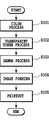
- Fig. 3 is a flow chart in regard to an image process for a one-pass print-out process using transparent toner
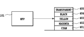
- Fig. 4 is a diagram showing an adhesion method of toner at a tow-pass print-out process
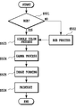
- Fig. 5 is a flow chart in regard to an image process for the two-pass print-pout process using transparent toner
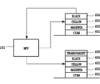
- Fig. 6 is a diagram showing an adhesion method of toner at the tow-path print-out process
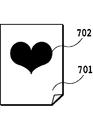
- Fig. 7 is a diagram showing an example of transparent form image data
- Fig. 1 is a block diagram showing an image processing system according to the present invention
- Fig. 2 is a block diagram showing an image forming device according to the present invention
- Fig. 3 is a flow chart in regard to an image process for a one-pass print-out process using transparent toner
- FIG. 8 is a diagram showing an example displayed on an UI screen;
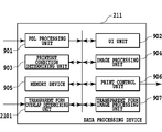
- FIG. 9 is a block diagram showing the configuration of a data processing device;
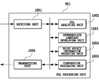
- Fig. 10 is a block diagram showing the configuration of a PDL processing unit;
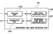
- Fig. 11 is a block diagram showing the configuration of a transparent form image processing unit;
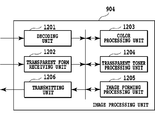
- Fig. 12 is a block diagram showing the configuration of an image processing unit;
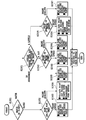
- Fig. 13 is a flow chart showing an outline of the present invention;
- Fig. 14 is a flow chart showing an outline of the present invention;
- Fig. 15 is a flow chart showing an outline of the present invention;
- Fig. 16 is a diagram showing a cross section after forming an image at the two-path print-out process;
- Fig. 17 is a flow chart showing an outline of the present invention;
- Fig. 9 is a block diagram showing the configuration of a data processing device;
- Fig. 10 is a block diagram showing the configuration of a PDL processing unit;
- Fig. 18 is a block diagram showing the configuration of a local PC
- Fig. 19 is a diagram showing an example displayed on the UI screen
- Fig. 20 is a block diagram showing the configuration of transparent form image data
- Fig. 21 is a block diagram showing the configuration of the data processing device
- Fig. 22 is a flow chart showing an outline of the present invention
- Fig. 23 is a flow chart showing an outline of the present invention
- Fig. 24 is a block diagram showing the configuration of a transparent form overlap determining unit
- Fig. 25 is a diagram showing an example displayed on the UI screen
- Fig. 26 is a diagram showing an example displayed on the UI screen
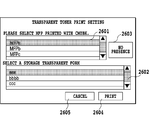
- Fig. 27 is a diagram showing an example displayed on the UI screen
- Fig. 28 is a block diagram showing the configuration of the data processing device
- Fig. 29 is a flow chart showing an outline of the present invention
- Fig. 30 is a diagram showing a cross section after forming an image at the one-path print-
- Fig. 1 is a block diagram showing an image forming device according to the present invention.
- Multi function complex machines (hereinafter, referred to as MFP) 101 and 103 as printing devices and a local PC 102 are connected to LAN 104 built in an office 10.
- MFP 101 and 103 performs an image process to an input image read from an original image. Further, MFP which has read the original image prints out the result of the image process.
- MFP 103 may print out the result of the image process. Further, a page description language (hereinafter, referred to as PDL) transmitted from the local PC 102 is interpreted, which may be printed out by MFP 101 or 103. MFP 105 is connected to a different LAN. ⁇ MFP>
- Fig. 2 is a diagram showing MFP.
- an image scanner (image reading unit) 201 reads an original image and performs a digital signal process.
- a printer unit 202 prints out an image corresponding to the original image read by the image scanner 201 on a paper in full color.
- the image scanner 201 includes a mirror surface pressure plate 200 and an original 204 on an original base glass (hereinafter, referred to as platen) 203 is radiated by a lamp 205, which is introduced to mirrors 206, 207, and 208.
- the radiated light builds up a picture on a solid-state image sensor (hereinafter, referred to as CCD) 210 with three lines by a lens 209, and three image signals of red (R), green (G) and blue (B) as full color information are transmitted to a data processing device 211.
- CCD solid-state image sensor
- the lamp 205 mechanically moves in a direction vertical to an electrical scan direction (main scan) of a line sensor at a speed of v and the mirrors 207 and 208 mechanically moves in the same way at a speed of 1/2 v to scan (sub scan) an entire surface of the original.
- the original 204 is read in both the main scan and the sub scan, for example, with resolution of 600 dpi (dots/inch).
- the read image signals are accumulated in data accumulating means (not shown) inside the data processing device 211 in a unit of one page of the original.
- the image signals accumulated therein are electrically processed in a pixel unit to be decomposed into respective components of magenta (M), cyan (C), yellow (Y) and black (Bk), which will be transmitted to the printer unit 202.
- M magenta
- C cyan
- Y yellow
- Bk black
- transparent image data (CL) are generated in a pixel unit, which are likewise transmitted to the printer unit 202.
- a rotational developing device 218 includes a magenta developing unit 219, a cyan developing unit 220, a yellow developing unit 221, a black developing unit 222 and a clear (transparent) developing unit 223.
- the five developing units 219 to 223 alternately contact the photosensitive drum 217 to develop an electrostatic development formed on the photosensitive drum 217 by toner of each color.
- a transcriptional drum 224 winds a paper fed from a paper cassette 225 or a paper cassette 226 around the transcriptional drum 224 to transcribe an image developed on the photosensitive drum on the paper.
- the paper may be once more subject to the above process without being discharged to be once more printed out, and then may be discharged.
- An example of the method of once more printing out without being discharged includes a method where in a reverse path used at double-sided printing out, a paper is once more set to a paper feeding step without being reversed.
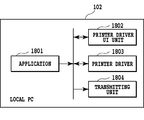
- Fig. 18 is a diagram showing the configuration of the local PC 102.
- Data produced by an application 1801 are explained as an example (hereinafter, referred to as application data).
- application data In a case where image data are stored in a memory device inside MFP or printed out by a user, a printer driver UI (user interface) unit 1802 instructed transmits the instruction to a printer driver 1803.
- the printer driver 1803 converts the application data into PDL data.
- PDL language used in PDL data indicates, for example, LIPS or PS.
- a transmitting unit 1804 transmits the produced PDL data to MFP 101.
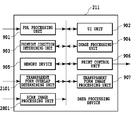
- Fig. 9 is a diagram showing the configuration of the data processing device 211 mounted in MFP and the data processing device 211 is configured of a PDL processing unit 901, a UI unit 902, a printout condition determining unit 903, an image processing unit 904, a memory device 905, a printout controlling unit 906 and a transparent form image processing unit 907.
- the data processing device and respective units included therein are operated by performing programs stored in the memory device 905 with CPU (not shown).
- Fig. 10 is a diagram showing the configuration of the PDL processing unit 901 in Fig. 9, which is configured of a receiving unit 1001, a PDL analyzing unit 1002, an intermediate language developing unit 1003, a print effect information producing unit 1004, a compression processing unit 1005 and a transmitting unit 1006.
- Fig. 11 is a diagram showing the configuration of the transparent form image processing unit 907 in Fig. 9, which is configured of an decoding unit 1101, a gray scale processing unit 1102, a binarization processing unit 1103 and a transmitting unit 1104.
- Fig. 12 is a diagram showing the configuration of the image processing unit 904 in Fig. 9, which is configured of an decoding unit 1201, a transparent form receiving unit 1202, a color processing unit 1203, a transparent toner processing unit 1204, an image forming processing unit 1205 and a transmitting unit 1206. ⁇ One-Path Print-Out Process>
- Fig. 3 is a diagram showing a flow chart in regard to an image process and a one-path print-out process performed by the data processing device 211.
- the procedure shown in this flow chart is stored in the memory device 905 in the data processing device 211 and is carried out by CPU (not shown).
- R, G and B signals from the local PC 102 or MFP 101 and 103 are converted into CMYBk signals at the color processing unit 1203 by the image processing unit 904.
- the conversion into the CMYBk signal is carried out by a matrix calculation as shown in Expression (1).
- the local PC 102 may transmit the CMYBk signals, but in this case, the color processing unit 1203 performs the concentration adjustment or the like at step S301.
- the color processing unit 1203 calculates transparent toner components from the CMYBk signals at the transparent toner processing unit 1204.
- a total toner amount of CMYBk is found for each pixel.
- the total toner amount is a toner amount transcribed on a paper for each pixel by a sum of signal quantities found by combining four colors of CMYBk.
- the total toner amount is usually expressed as a percentage value of which the single color maximum value is 100%. In a case where the image signal is expressed in the integer number of 8 bits, since the single color maximum value is 255, the total toner amount is determined by multiplying an additional value of CMYBk by 100/255.
- a general upper limit value of the total toner amount is usually in the order of 200 to 280% and is determined by an image producing process, but in the present embodiment, a total amount after further forming a transparent toner layer is required to be equal to or less than the upper limit value.
- the image processing unit 904 performs a gamma correction process set by MFP 101 for each color at the image forming processing unit 1205.
- the image forming processing unit 1205 performs an image forming process for each color.
- the image forming processing includes a screen process or an error diffusion process.
- MFP 101 uses the toner of CMYBk and CL to print out an image.
- Fig. 4 shows the outline diagram.
- a one-path print-out process means a printout method in which the transparent toner amount is calculated from the total toner amount of the four colors of cyan, magenta, yellow and black, and the printing and fixing are performed one time, thus using a regular printout (first printout) function completing the printout by one process.
- Fig. 5 is a flow chart in regard to an image process and a two-path print-out process performed by the data processing device 211.
- the procedure shown in this flow chart is stored in the memory device 905 in the data processing device 211 and is performed by CPU (not shown).
- the image processing unit 904 determines whether input image signals from the local PC 102 or the MFP 101 and 103 are R, G, and B signals or CMYBk signals at the color processing unit 1203. In a case where as a result of the determination, the input image signal is the CMYBk signal, at step S502 the image processing unit 904 converts the CMYBk signal into the R, G and B signal at the color processing unit 1203. The method of the conversion is carried out by the matrix calculation as shown in Expression (4).
- the color processing unit 1203 replaces the R, G and B signals for one signal of a single color.
- the method of the conversion is carried out using a calculating expression or the like and the calculating expression is not uniform.
- the CMYBk signals are converted into the R, G and B signals, which then are replaced by the one signal of the single color, but it is possible to directly replace the CMYBk signals for the one signal of the single color using the well known method.
- the image processing unit 904 performs a gamma correction process for transparent toner set by the MFP 101 to the signal converted into one signal at the image forming processing unit 1205. Further, at step S505 the image forming processing unit 1205 performs the image forming process.
- MFP 101 prints out an image using toner of CL.
- the schematic diagram is shown in Fig. 6.
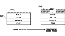
- MFP 101 first prints cyan 601, magenta 602, yellow 603 and black 604 in that order and performs the printout.
- a printout document by the CMYBk is set to a paper feeding step of MFP 101.
- a transparency 605 is printed and printed out on the set printout document.
- the two-path print-out process is a printout method using a two-path print-out (second printout) function in which four colors of cyan, magenta, yellow and black (C, M, Y and Bk) are fixed once, and thereafter, transparent toner is printed thereon, thus completing the printout with two processes.
- a feature of the two-path print-out process by a case compared with the one-path print-out process will be explained.
- Using the two-path print-out process a total time required for the printout increases without mentioning.
- a print amount of the transparent toner is a difference amount found by subtracting the CMYBk amount from the upper limit value of the total toner amount
- an amount for printing the transparent toner may be zero according to the calculation. For example, this is a case where a total toner amount of CMYBk exceeds a total toner amount allowed by a printout device. In this case, even if a user intends to print the transparent toner, a visual effect by the transparent toner can not be obtained.
- the transparent toner is printed and fixed.
- the transparent toner can be printed in an adhesion amount of 100% as the maximum value of a single color.
- the transparent toner of the instructed adhesion amount can be printed to restrict reduction of the visual effect.
- Fig. 30 is a diagram showing a surface of transparent toner at the time of usually printing out.
- Fig. 16 is a diagram showing a surface of transparent toner at a two-path print-out process.
- the print effect depends on a difference in surface properties between a paper and transparent toner and a difference in surface properties between transparent toner and toner already printed.
- a paper there is a difference in surface between a coated paper 3001 and a non-coated paper 3002 as a plain paper in Fig. 30. Since a surface 3003 of the coated paper 3001 is coated, it has no concavity and convexity. On the other hand, a surface 3004 of the non-coated paper 3002 has concavity and convexity due to an influence of paper fabric.
- both the surfaces of the paper and the transparent toner have concavity and convexity.
- the concavity and convexity on the surface of the non-coated paper 3002 are larger that those on the surface 3006 of the transparent toner, a gloss effect occurs on the printed location (that is, the surface 3006 of the transparent toner).
- Fig. 7 shows an example of transparent form image data.
- Fig. 8 shows an example of an image shown on the local PC screen.
- Transparent form image data 701 are stored in binary image data, and a location 702 of a logical value "1" shows a position subject to a visual effect generated at the time of using the transparent toner. Bottoms 801 and 802 instruct to a print effect information producing unit 1004 of the PDL processing unit 901 which effect a user desires in the location 702 of the logical value "1" in the form image 701 shown in a preview 803. ⁇ Transparent Form Image Registration>
- JPEG Joint Photographic Experts Group
- the image processing unit 904 uses transparent form image data at the time of printing transparent toner at the transparent toner processing unit 1204.
- the memory device 905 registers an image showing a location for creating the effect by the transparent toner as transparent form image data.
- the PDL processing unit 901 receives PDL data transmitted from the local PC 102, at the receiving unit 1001.
- the image data received for being registered as the transparent form image data are not only data received from the local PC 102, but also may be based on image data obtained from an image scanned by the image scanner 201 of MFP.
- the PDL analyzing unit 1002 analyzes the PDL data to generate intermediate data. In a case of registering a transparent form image at step S1302, step S1303 is skipped, and at step S1304, the intermediate language developing unit 1003 performs rendering to the intermediate data to generate image data.
- the compression processing unit 1005 compresses the image data to generate compression data.
- the transmitting unit 1006 transmits the compression data toward the decoding unit 1101 in the transparent form image processing unit 907.
- the decoding unit 1101 decodes the received compression data.
- the gray scale processing unit 1102 converts the decoded image data into data of the gray scale.
- An example of the conversion method includes a case where in a case of being input in RGB, the data are converted into YUV signals, and only the Y signal is used as a gray scale signal, but is not limited thereto.
- the binarization processing unit 1103 converts the image signal converted into the gray scale into binary image data.
- An example of the conversion method includes a method in which a threshold value is set, and when a gray scale signal value is larger that the threshold value, the data is "1" and when the gray scale signal value is smaller that the threshold value, the data is "0", thus generating the binary image data.
- the transmitting unit 1103 transmits the binary image data to the memory device 905.
- the memory device 905 receives the binary image data, which is stored as the transparent form image data therein. ⁇ Printing Using Transparent Toner>
- the transparent form image data stored in the memory device 905 are used to realize the printing using transparent toner.
- the printer driver UI unit 1802 displays Fig. 8 on the screen.
- the printer driver UI unit 1802 selects the transparent form image data to be used at printing out from many stored transparent form image data at a selection area 804.
- the printer driver UI unit 1802 displays the preview 803 on the screen, making it possible to confirm the binarized transparent form image data.
- the printer driver UI unit 1802 determines the print effect to a portion (location of logical value "1" in the binary image data) displayed on the preview 803.
- the printer driver UI unit 1802 transmits to the printer driver 1803 an instruction from the button 801 in a case of producing a matte effect and an instruction from the button 802 in a case of producing a gloss effect, according to an instruction of a button 805. Finally the transmitting unit 1804 transmits the PDL data generated in the printer driver 1803. An instruction of a button 806 instructs cancellation.
- the receiving unit 1001 in the PDL processing unit 901 receives PDL data from the local PC 102.
- the process flow in the PDL processing unit 901 is almost the same as at the time of registering the transparent form image.
- the PDL analyzing unit 1002 analyzes whether the PDL data require the matte effect or the gloss effect to produce the print effect information.
- the transmitting unit 1006 transmits the print effect information to the printout condition determining unit 903.
- the transmitting unit 1006 transmits the compressed image data to the image processing unit 904.
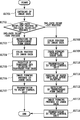
- the printout condition determining unit 903 determines whether the print effect information is the matte effect or the gloss effect. In a case where the matte effect is selected, the process goes to step S1505. That is, the printout condition determining unit 903 determines to adopt a one-path print-out process as the printing method and use a coated paper as the paper type. In addition, the determination information is generated based upon this result. Then the process goes to step S1506, wherein the determination information is transmitted to the image processing unit 904. Next, in a case where the gloss effect is selected, the process goes to step S1502. That is, the printout condition determining unit 903 determines whether selection of the priority matter in advance set at MFP 101 is print quality priority or print speed priority.
- the print speed priority is selected, first the one-path print-out process is prioritized rather than the two-path print-out process requiring more printing process time. In most cases, a coated paper requires more time for transportation as compared to a non-coated paper. Based upon these matters, in a case where the print speed is prioritized, the process goes to step S1503, wherein the printout condition determining unit 903 determines to adopt the one-path print-out process as the printing method and use the non-coated paper as the paper type. In addition, the determination information is generated based upon this result. Then the process goes to step S1506, wherein the determination information is transmitted to the image processing unit 904.
- the two-path print-out process in which a transparent toner amount is not limited by an adhesion amount of toner as compared to the one-path print-out process.
- an amount of the transparent toner required for producing the gloss effect may not adhere due to the toner adhesion amount limit.
- the visual effect is reduced due to the toner adhesion amount limit. Therefore, when the two-path print-out process which is not subject to the limit by the toner adhesion amount is adopted, the reduction of the gloss effect can be avoided. Further, the coated paper can more effectively produce a glossy feeling to a portion requiring the gloss effect.
- step S1504 the printout condition determining unit 903 determines to adopt the two-path print-out process as the printing method, use the coated paper as the paper type and reverse the transparent form image data. In addition, the determination information is generated based upon this result. Then the process goes to step S1506, wherein the determination information is transmitted to the image processing unit 904.
- the image processing unit 904 at step S1701 decodes the image data received from the decoding unit 1201.
- the image processing unit 904 determines whether the printing method is the one-path print-out process or the two-path print-out process from the determination information.
- the transparent form receiving unit 1202 receives transparent form image data from the memory device 905. Further, when the binary image data in the transparent form image data are required to be reversed from the determination information, the reversing work is also performed.
- the color processing unit 1203 converts the RGB image data into CMYBk image data to adjust the concentration by a calculating process or the like.
- the concentration is adjusted by the calculating process or the like.
- the transparent toner processing unit 1204 performs the one-path print-out process to a location of a logical value "1" in the transparent form image data, that is, the binary image data to determine a transparent toner amount.
- any print-out process is performed in a location of the logical value "0" in the binary image data to generate image data including a transparent toner plate.
- the image forming processing unit 1205 performs a gamma correction process set in MFP 101 to each plate (CMYBk and transparency) to perform an image forming process.
- the method of the image forming process is performed by a screen or error diffusion.
- the transmitting unit 1206 transmits the image data after the image forming process to the print control unit 906.
- step S1702 in a case where it is determined that the printing method is the two-path print-out process, at step S1708 the color processing unit 1203 performs a color process to the image data.
- the image forming processing unit 1205 performs the gamma correction process set in MFP to each plate (CMYBk) to perform the image forming process.
- the transmitting unit 1206 transmits the image data after the image forming data process to the print control unit 906.
- the print control unit 906 first prints out the image data formed with CMYBk by the determination information.
- the paper is not discharged to the paper discharging mechanism in MFP 101, and at step S1711 MFP 101 automatically sets the paper to the paper feeding step one more.
- MFP 101 automatically sets the paper to the paper feeding step one more.
- the paper is again set to the paper feeding step without being reversed.
- the paper is discharged to the paper discharging mechanism in MFP 101 and a display prompting a user to once more set the discharged print paper to the paper feeding step through the UI unit 902 may be made.
- the transparent form receiving unit 1202 receives the transparent form image data from the memory device 905.
- the image forming processing unit 1205 performs the gamma correction process for transparent toner set in MFP to the transparent form image data to perform the image forming process for transparent toner.
- the transmitting unit 1206 transmits the image data after the image forming process by the transparent toner to the print control unit 906.
- the print control unit 906 selects the paper type according to the determination information for the printing out.
- the printing method for realizing the effect instructed by a user to the printing portion using the transparent toner, the printing method can be automatically selected.
- the information on whether the print quality or the print speed is prioritized is in advance set in MFP, and the process can be automatically performed based upon this information.
- Embodiment 1 has the feature that at the printing, the information on whether the print quality or the print speed is prioritized is in advance set in MFP, and the printing method can be automatically performed based upon this information.
- Embodiment 2 has the feature of making a user select the print quality priority or the print speed priority.
- Fig. 19 shows an example of a screen displayed on the local PC screen.
- step S1502 in Fig. 15 the printer driver UI unit 1802 displays Fig. 19 on the screen of the local PC 102.
- the printer driver UI unit 1802 displays selectable priority matters and a print setting in each case on a button.
- a button 1901 performs an instruction of the print speed priority.
- the process goes to step S1503.
- the printout condition determining unit 903 determines to adopt a one-path print-out process as the printing method and use a non-coated paper as the paper type.
- the determination information is generated based upon this result.
- step S1506 wherein the determination information is transmitted to the image processing unit 904.
- a button 1902 performs an instruction of the print quality priority.
- the printout condition determining unit 903 determines to adopt a two-path print-out process as the printing method, use a coated paper as the paper type and reverse transparent form image data.
- the determination information is generated based upon this result. Then the process goes to step S1506, wherein the determination information is transmitted to the image processing unit 904.
- Embodiment 2 in addition to Embodiment 1, a user can select the priority matter, and further, can know a detail of the set matter. (Embodiment 3)
- Embodiment 1 and Embodiment 2 the transparent toner is assumed to be printed in the same shape as the image data.
- Embodiment 3 has the feature that for printing the transparent toner in a shape different from that of the image data, the image data and the transparent form image data (binary image data) are compared, and the determination information is produced based upon an overlap degree thereof.
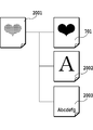
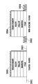
- Fig. 20 is a diagram showing a combination of the image data and the transparent form image data.
- Fig. 21 is a diagram showing the configuration of the data processing unit 211 mounted in MFP and is configured of a transparent form overlap determining unit 2101.
- the transparent form image data assumed at the time of printing transparent toner on image data 2001 are classified into the following three data.
- Data 701 in conformity with the image data 2001, data 2002 which mostly overlap with the image data 2001 and data 2003 which do not overlap with the image data 2001 at all can be assumed.
- the printer driver UI unit 1802 When the printer driver UI unit 1802 instructs the printing using the transparent form image data, the printer driver UI unit 1802 displays Fig. 8 on the local PC 102.
- the printer driver UI unit 1802 selects the transparent form image data used at printing from many stored transparent form image data at the selection area 804. Next, an instruction is made on selection of the button 802 and the button 803, and finally according to an instruction of a button 805, the printer driver 1803 produces PDL data, which are transmitted to the transmitting unit 1804.
- the PDL processing unit 901 processes the generated PDL data
- the generated image data 2001 are transmitted to the transparent form overlap determining unit 2101. Further, the memory device 905 transmits the selected transparent form image data to the transparent form overlap determining unit 2101.
- Fig. 24 is a block diagram showing the configuration of the transparent form overlap determining unit 2101. An operation flow of the transparent form overlap determining unit 2101 will be explained with reference to Fig. 22.
- the transparent form image data and the image data are received.
- a count unit 2402 counts the pixel number of pixels in the logical value "1" in the transparent form image data received at the transparent form receiving unit 2403.
- the transparent form overlap determining unit 2101 counts the pixel number having the color value of the image data decoded at the decoding unit 2401 by the count unit 2402.
- a count comparing unit 2404 compares the pixel number of pixels of the logical value "1" counted previously with the pixel number having the color value in the decoded image data. In a case where the results of the comparison are equal, at step S2207 the count comparing unit 2404 determines that the overlap information is equal.
- the count comparing unit 2204 compares how much pixels having the color value in the image data have at a position of the pixel in the logical value "1" in the transparent form image data at the count comparing unit 2404. In a case of almost no overlap with the image data 2001 as the transparent form image data 2003, at step S2205 the count comparing unit 2404 determines that the overlap information is "a little". In a case where many portions overlapping with the image data 2001 as the transparent form image data 2002 exist, at step S2206 the count comparing unit 2404 determines that the overlap information is "a lot”. At step S2208 the information generated in this way is transmitted to the printout condition determining unit 903 by the transmitting unit 2405.
- the printout condition determining unit 903 determines whether the print effect information is the matte effect or the gloss effect. In a case where the gloss effect is selected, the process goes to step S1502 in the same way as Embodiment 1. In a case where the matte effect is selected, the process goes to step S2301. In addition, the printout condition determining unit 903 determines the received overlap information. In a case where the overlap information is "equal", the process goes to step S1505 in the same way as Embodiment 1.
- the process goes to step S2302, wherein the printout condition determining unit 903 determines the print quality priority or the print speed priority.
- the one-path print-out process is, as described above, adopted with priority rather than the two-path print-out process. In consequence, the one-path print-out process is adopted as the printing method.
- it is preferable that a non-coated paper is used as the paper type from a viewpoint of the print speed.
- the non-coated paper is used in a case where the overlap information is "equal" or "a lot"
- a defective occurs in printing.
- the transparent form is reversed for printing.
- the transparent toner is added to a portion on the non-coated paper with no image data (or a few image data).
- toner of CMYBk is added to the image data portion.
- the image portion as the portion where the CMYBk toner is added creates rather a glossy feeling. That is, the image portion for desiring to obtain the effect of "matte” creates rather a glossy feeling. Such a defective occurs.
- the coated paper is determined to be used in a case where the overlap information is "equal" or "a lot” so that in any case, the defective does not occur.
- the determination information is generated based upon this result.
- the two-path print-out process in which a toner adhesion amount is not limited is adopted as the printing method.
- the coated paper in which the visual effect more remarkably appears is used ad the paper type.
- the printout condition determining unit 903 determines the print quality priority or the print speed priority.
- the printout condition determining unit 903 adopts the one-path print-out process as the printing method. In a case where the overlap information is "a little", since the defective as shown above does not occur, the non-coated paper of which transportation is faster than the coated paper is determined to be used as the paper type. The determination information is generated based upon this result. In a case where it is determined that the print quality priority is selected, the printout condition determining unit 903 determines to adopt the two-path print-out process as the printing method, use the coated paper as the paper type and reverse the transparent form image data. The determination information is generated based upon this result. At step S2308, the determination information is transmitted to the image processing unit 904 and the print control unit 906.
- Embodiment 3 in addition of Embodiment 1 and Embodiment 2, it is possible to more accurately set the printout condition based upon an overlap degree between the image data and the transparent form image data. It should be noted that if the instructed effect or priority can be realized, the printing method may be selected in consideration of an adhesion amount of toner, surface properties of a paper and transparent toner, and a difference component in surface properties between the transparent toner and the toner already printed. (Embodiment 4)
- Embodiment 1 and Embodiment 3 the determination information is automatically produced based upon the effect desired by a user and the overlap degree between the image data and the transparent form image data.
- Embodiment 4 has the feature of automatically determining a control method in a case where a finisher in which a mechanism (hereinafter, referred to as glosser) for enhancing gloss is built is mounted in MFP 101.
- the glosser (not shown) is a device in which heat is once more added to the toner once fixed at MFP 101 to melt the surface for the re-fixing.
- a printout document which has passed the glosser can realize high gloss. That is, even if the printing is performed at MFP 101 based upon the determination condition set in Embodiment 1 or Embodiment 3 by a user's desire to the matte effect, when the finisher built-in glosser is mounted, it is impossible to realize the matte effect.
- the printout condition determining unit 903 adds to the determination information the printout to a paper discharging opening different from the finisher built-in glosser.
- the image processing unit 904 and the print control unit 906 receive the determination information.
- Embodiment 4 in addition of Embodiment 1 and Embodiment 3, even if the finisher built-in glosser is mounted in MFP, it is possible to realize the effect desired by a user. (Embodiment 5)
- Embodiment 1 and Embodiment 3 the determination information is automatically produced based upon the effect desired by a user and the overlap degree between the image data and the transparent form image data.
- Embodiment 5 has the feature of making a user select the effect that a user can print, based upon only the overlap degree between the image data and the transparent form image data.
- Fig. 25 shows an example of a screen displayed on the local PC screen.
- the printer driver UI unit 1802 When the printer driver UI unit 1802 instructs the print using the transparent form image data, the printer driver UI unit 1802 displays Fig. 8 on the local PC 102. The printer driver UI unit 1802 selects transparent form image data used at printing from many stored transparent form image data at the selection area 804. Then, the printer driver UI unit 1802 displays the preview 803 on the screen of the local PC 102, thereby making it possible to confirm the binarized transparent form image data. Finally according to an instruction of the button 805, the printer driver 1803 produces PDL data, which are transmitted to the transmitting unit 1804.
- the printout condition determining unit 903 generates the determination information only by determining the priority matter in advance set at MFP 101.
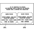
- the generated determination information is displayed on the local PC screen in Fig. 25, and a user can select the print effect.
- a button 2501 instructs the printout with a matte effect, and the setting at that time also displays that the printing method is a one-path print-out process and the paper is a coated paper.
- a button 2502 instructs the printing with a gloss effect, and also displays that the printing method is the one-path print-out process, the paper is the coated paper and the transparent form image data are reversed.
- the image processing unit 904 and the print control unit 906 receive the determination information.
- Embodiment 6 since the effect accomplished by printing is displayed, the print effect can be simply realized only by a user's selection without paying attention to the print effect particularly. (Embodiment 6)
- Embodiment 1 and Embodiment 3 the determination information is automatically produced based upon the effect desired by a user and the overlap degree between the image data and the transparent form image data.
- Embodiment 6 has the feature of displaying to a user a measurement method when the limit to the paper type occurs.
- a printing operation is started based upon the determination information automatically produced from the effect desired by a user and the overlap degree between the image data and the transparent form image data, but although the paper type of the determination information is the coated paper, the coated paper may not be mounted.
- the printer driver UI unit 1802 displays a screen of informing a user of mounting the coated paper on the screen of the local PC 102.
- the printer driver UI unit 1802 displays a screen of providing a user with a warning that the mounted paper type is used as an alternative but the print effect may not live up to the user's expectations, on the screen of the local PC 102 (not shown).
- the printout condition determining unit 903 determines whether or not a desired (given) print effect can be produced with the paper type. In a case where the desired print effect can not be produced, the printer driver UI unit 1802 displays a warning screen that the print effect may not live up to the expectations, on the screen of the local PC 102 (not shown).
- Embodiment 6 it is possible to prompt a user to perform a measurement in a case where the paper type with which the desired effect can be obtained is not mounted. (Embodiment 7)
- Embodiment 1 and Embodiment 3 the determination information is automatically produced based upon the effect desired by a user and the overlap degree between the image data and the transparent form image data.
- Embodiment 7 has the feature of automatically producing the determination information in a case where transparent toner is used to a printout document already printed to realize the print effect. In this case, a transparent image having a configuration corresponding to that of the printout document already printed is added to the printout document.
- Fig. 26 and Fig. 27 are diagrams each showing an example displayed on the screen of the UI unit 902 in MFP 101.
- Fig. 28 is a diagram showing the configuration of the data processing device 211 mounted in MFP 101 and is configured of a scan image processing unit 2801.
- MFP 103 performs printing with four colors of CMYBk. At that time, MFP 103 performs a gray scale process and binarization to the generated image data, which are stored in the memory device built in MFP 103.
- the paper feeding step in MFP 101 sets the printout document discharged from the MFP 103.
- the UI unit 902 in MFP 101 displays a screen of Fig. 26 on a control panel (not shown) in MFP 101.
- the UI unit 902 displays a list of MFP connected to LAN 104 in the same as MFP 101 to select MFP 103 which has performed the printing with four colors of CMYBk from a selection area 2601.
- the UI unit 902 selects MFP 103, at the selection area 2602 there is selected an image corresponding to the printout document set to the paper feeding step from the binarized images stored in the memory device built in MFP 103.
- the UNI unit 902 determines selection of form images and selection of print effects at MFP 101.
- An instruction of a button 2605 means cancellation.
- the transparent form overlap determining unit 2101 receives the binarized image data from MFP 103 when the selection of the transparent form image data and the selection of the print effects at MFP 101 by the UI unit 902 are completed and the printing operation is started.
- the transparent form overlap determining unit 2101 makes the determination using the binarized image data and the selected transparent form image data.
- the UI unit 902 does not display MFP 105 on the selection area 2601. According to an instruction of a button 2403, the UI unit 902 displays Fig. 27 on the control panel of the MFP 101.
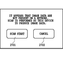
- An original reading device of MFP 101 sets the printout document printed in four colors and reads the printout document printed in four colors according to an instruction of a button 2701, which is obtained as image data.
- the scan image processing unit 2801 performs an image process for scan (color process, base removing or the like) to the obtained image data, which are transmitted to the transparent form overlap determining unit 2101.
- An instruction of a button 2702 means cancellation of the reading-in operation.
- the UI unit 902 in MFP 101 selects the transparent form image data from the selection area 804 on the screen of Fig. 8 displayed on the control panel by the UI unit 902, selects the print effect from the button 801 and the button 802 and starts with a printing operation according to the instruction of the button 805.
- the overlap form determining unit 2101 determines the overlap degree between the image data and the transparent form image data.
- the printout condition determining unit 903 After determining the overlap degree, even if the printing by four colors of CMYBk is performed by either one of MFP 103 and MFP 105, the printout condition determining unit 903 generates the determination information. As candidates in this case, since Embodiment 7 performs the printing by the two-path print-out process, only step S1504, step S2304, and step S2307 can be selected.
- the transparent form receiving unit 1202 receives the selected transparent form image data from the memory device 905. Further, in a case where the binary image data in the transparent form image data are required to be reversed from the determination information, the reverse work is also carried out.
- the image forming processing unit 1205 performs an image forming process to the transparent form image data.
- the transmitting unit 1206 transmits the image data to the print control unit 906.
- Embodiment 7 in addition to Embodiment 1 and Embodiment 3, it is possible to realize the print effect to the printout document already printed.
- the output by PDL is described, but the present invention is not limited thereto.
- the same can be applied to the output by scan.
- an operation similar to that of PDL is performed.
- the screen displayed on the screen of the local PC 102 is displayed on the screen of the control panel in MFP 101.
- the scope of the aforementioned embodiment also includes a processing method in which a program for operating the configuration of the above embodiment so as to realize the function of the above embodiment is stored in a recording medium and the program stored in the recording medium is read out as a code, which is performed by a computer.
- aspects of the present invention can also be realized by a computer of a system or apparatus (or devices such as a CPU or MPU) that reads out and executes a program recorded on a memory device to perform the functions of the above-described embodiment(s), and by a method, the steps of which are performed by a computer of a system or apparatus by, for example, reading out and executing a program recorded on a memory device to perform the functions of the above-described embodiment(s).
- the program is provided to the computer for example via a network or from a recording medium of various types serving as the memory device (e.g., computer-readable medium).
- the recording medium is a computer readable recording medium.
- the recording medium in which the above program is stored but also the program itself can be included in the aforementioned embodiment.
- An example of such a recording medium may include a floppy (registered trademark) disc, a hard disc, an optical disc, an optical magnetic disc, CD-ROM, a magnetic tape, an involatile memory card and ROM.
- the embodiment includes not only the device of performing the process with the program unit stored in the aforementioned recording medium, but also a device which operates in operational sequence in cooperation with the other software and a function of an expansion board to perform the operation of the aforementioned embodiment.
Landscapes
- Physics & Mathematics (AREA)
- General Physics & Mathematics (AREA)
- Engineering & Computer Science (AREA)
- Microelectronics & Electronic Packaging (AREA)
- Human Computer Interaction (AREA)
- Color Electrophotography (AREA)
- Control Or Security For Electrophotography (AREA)
Abstract
Description
[PTL 2] Japanese Patent Laid-Open No. 2005-119279
<MFP>

<Local PC>
<
<One-Path Print-Out Process>


<Two-Path Print-Out Process>

<Print effect by Transparent Toner>
<Transparent Form Image Data>
<Transparent Form Image Registration>
<Printing Using Transparent Toner>
(Embodiment 2)
(Embodiment 3)
(Embodiment 4)
(Embodiment 5)
(Embodiment 6)
(Embodiment 7)
(Other Embodiments)
Claims (20)
- An image forming device comprising:
first selecting means for selecting a gloss effect creating a glossy feeling to a printout document or a matte effect creating a matte feeling to the printout document in a case of printing an input image on a print paper to obtain the printout document;
second selecting means for selecting quality priority for prioritizing a quality of the printout document or speed priority for prioritizing a print speed thereof;
first printout means for, in a case where the matte effect is selected by the first selecting means, printing the image on a coated paper for obtaining the printout document using toner of four colors of cyan, magenta, yellow and black and transparent toner to complete printing by one-time fixing;
second printout means for, in a case where the gloss effect is selected by the first selecting means and the quality priority is selected by the second selecting means, printing and fixing the image on the coated paper using the toner of the four colors of the cyan, magenta, yellow and black for obtaining the printout document, and thereafter, further printing and fixing reverse transparent form image data obtained by reversing transparent form image data printed using transparent toner among image data constituting the input image using the transparent toner; and
third printout means for, in a case where the gloss effect is selected by the first selecting means and the print speed is prioritized by the second selecting means, printing the image on a plain paper using the toner of the four colors of the cyan, magenta, yellow and black and the transparent toner for obtaining the printout document to complete printing with one-time fixing.
- The image forming device according to claim 1, further comprising:
displaying means for displaying a screen for making a user select the priority document.
- The image forming device according to claim 1, wherein
the priority document is in advance set and stored in the device.
- The image forming device according to claim 1, further comprising:
generating means for generating overlap information showing an overlap amount between image data printed using the toner of the four colors of the cyan, magenta, yellow and black and transparent form image data printed using the transparent toner constituting the input image, wherein
in a case the matte effect is selected by the first selecting means and it is determined that the overlap information of the input image generated by the generating means is a lot, when the print speed priority is selected by the second selecting means, the printing is performed by the first printout means, and when the print quality priority is selected by the second selecting means, the image data is printed and fixed on the coated paper using the toner of the four colors of the cyan, magenta, yellow and black and thereafter, further the transparent form image data are printed and fixed using the transparent toner to perform the printing.
- The image forming device according to claim 1, further comprising:
means for generating overlap information showing an overlap amount between the image data printed using the toner of the four colors of the cyan, magenta, yellow and black and the transparent form image data printed using the transparent toner constituting the input image, wherein
in a case the matte effect is selected by the second selecting means and it is determined that the overlap information of the input image generated by the generating means is a little, when the print speed priority is selected by the second selecting means, the printing is performed by the third printout means using the reverse transparent form image data, and when the print quality priority is selected by the second selecting means, the toner of the four colors of the cyan, magenta, yellow and black is used to perform the printing and fixing on the coated paper and thereafter, further the transparent form image data are printed and fixed using the transparent toner to perform the printing.
- The image forming device according to claim 1, wherein
in a case where a finisher built-in glosser is mounted and the matte effect is selected by the first selecting means, the printout document of the input image is outputted to a paper discharging opening different from the finisher built-in glosser.
- The image forming device according to claim 1, further comprising:
a user interface for receiving an instruction of the print effect in the first selecting means from a user.
- The image forming device according to claim 1, further comprising:
means for determining whether or not the print effect instructed by a user is produced to the printout document using a paper type to be fed in a case of instructing the paper type by the user at the time of obtaining the printout document and for issuing a warning to the user when the print effect is not produced.
- The image forming device according to claim 1, wherein
when the printout document already printed is fed, the image data are obtained from the printout document, and the transparent toner is added in such a manner as to realize the print effect selected by the first selecting means to the printout document using the image data.
- An image forming method comprising:
a first selecting step for selecting a gloss effect creating a glossy feeling to a printout document or a matte effect creating a matte feeling to the printout document in a case of printing an input image on a print paper to obtain the printout document;
a second selecting step for selecting quality priority for prioritizing a quality of the printout document or speed priority for prioritizing a print speed thereof;
a first printout step for, in a case where the matte effect is selected by the first selecting step, printing the image on a coated paper for obtaining the printout document using toner of four colors of cyan, magenta, yellow and black and transparent toner to complete printing by one-time fixing;
a second printout step for, in a case where the gloss effect is selected by the first selecting step and the quality priority is selected by the second selecting step, printing and fixing the image on the coated paper using the toner of the four colors of the cyan, magenta, yellow and black for obtaining the printout document, and thereafter, further printing and fixing reverse transparent form image data obtained by reversing transparent form image data printed using transparent toner among image data constituting the input image using the transparent toner; and
a third printout step for, in a case where the gloss effect is selected by the first selecting step and the print speed is prioritized by the second selecting step, printing the image on a plain paper using the toner of the four colors of the cyan, magenta, yellow and black and the transparent toner for obtaining the printout document to complete printing with one-time fixing.
- The image forming method according to claim 10, further comprising:
a displaying step for displaying a screen for making a user select the priority document.
- The image forming method according to claim 10, wherein:
the priority document is in advance set and stored in the device.
- The image forming method according to claim 10, further comprising:
a generating step for generating overlap information showing an overlap amount between image data printed using the toner of the four colors of the cyan, magenta, yellow and black and transparent form image data printed using the transparent toner constituting the input image, wherein
in a case the matte effect is selected by the first selecting step and it is determined that the overlap information of the input image generated by the generating step is a lot, when the print speed priority is selected by the second selecting step, the printing is performed by the first printout step, and when the print quality priority is selected by the second selecting step, the image data is printed and fixed on the coated paper using the toner of the four colors of the cyan, magenta, yellow and black and thereafter, further the transparent form image data are printed and fixed using the transparent toner to perform the printing.
- The image forming method according to claim 10, further comprising:
a step for generating overlap information showing an overlap amount between the image data printed using the toner of the four colors of the cyan, magenta, yellow and black and the transparent form image data printed using the transparent toner constituting the input image, wherein
in a case the matte effect is selected by the first selecting step and it is determined that the overlap information of the input image generated by the generating step is a little, when the print speed priority is selected by the second selecting step, the printing is performed by the third printing step using the reverse transparent form reversing the transparent form image data printed using the transparent toner constituting the input image, and when the print quality priority is selected by the second selecting step, the toner of the four colors of the cyan, magenta, yellow and black is used to perform the printing and fixing on the coated paper and thereafter, further the transparent form image data are printed and fixed using the transparent toner to perform the printing.
- The image forming method according to claim 10, wherein
in a case where a finisher built-in glosser is mounted and the matte effect is selected by the first selecting step, the printout document of the input image is outputted to a paper discharging opening different from the finisher built-in glosser.
- The image forming method according to claim 10, further comprising:
a user interface for receiving an instruction of the print effect in the first selecting step from a user.
- The image forming method according to claim 10, further comprising:
a step for determining whether or not the print effect instructed by a user is produced to the printout document using a paper type to be fed in a case of instructing the paper type by the user at the time of obtaining the printout document and for issuing a warning to the user when the print effect is not produced.
- The image forming method according to claim 10, wherein
when the printout document already printed is fed, the image data are obtained from the printout document, and the transparent toner is added in such a manner as to realize the print effect selected by the first selecting step to the printout document using the image data.
- A computer readable recording medium recording a program for carrying out the method according to any of claims 10 to 18 by a computer.
- A program for carrying out the method according to any of claims 10 to 18 by a computer.
Priority Applications (5)
| Application Number | Priority Date | Filing Date | Title |
|---|---|---|---|
| EP09819000.2A EP2344929B1 (en) | 2008-10-08 | 2009-10-08 | Image forming device |
| US12/989,953 US8531724B2 (en) | 2008-10-08 | 2009-10-08 | Image forming device |
| CN2009801016146A CN101910955B (en) | 2008-10-08 | 2009-10-08 | Image forming device |
| KR1020107014253A KR101123730B1 (en) | 2008-10-08 | 2009-10-08 | Image forming device |
| US13/974,107 US8786905B2 (en) | 2008-10-08 | 2013-08-23 | Image forming device |
Applications Claiming Priority (2)
| Application Number | Priority Date | Filing Date | Title |
|---|---|---|---|
| JP2008-261930 | 2008-10-08 | ||
| JP2008261930A JP4950977B2 (en) | 2008-10-08 | 2008-10-08 | Image forming apparatus |
Related Child Applications (2)
| Application Number | Title | Priority Date | Filing Date |
|---|---|---|---|
| US12/989,953 A-371-Of-International US8531724B2 (en) | 2008-10-08 | 2009-10-08 | Image forming device |
| US13/974,107 Continuation US8786905B2 (en) | 2008-10-08 | 2013-08-23 | Image forming device |
Publications (1)
| Publication Number | Publication Date |
|---|---|
| WO2010041460A1 true WO2010041460A1 (en) | 2010-04-15 |
Family
ID=42100421
Family Applications (1)
| Application Number | Title | Priority Date | Filing Date |
|---|---|---|---|
| PCT/JP2009/005262 WO2010041460A1 (en) | 2008-10-08 | 2009-10-08 | Image forming device |
Country Status (6)
| Country | Link |
|---|---|
| US (2) | US8531724B2 (en) |
| EP (1) | EP2344929B1 (en) |
| JP (1) | JP4950977B2 (en) |
| KR (1) | KR101123730B1 (en) |
| CN (1) | CN101910955B (en) |
| WO (1) | WO2010041460A1 (en) |
Cited By (2)
| Publication number | Priority date | Publication date | Assignee | Title |
|---|---|---|---|---|
| US20120057177A1 (en) * | 2010-09-08 | 2012-03-08 | Canon Kabushiki Kaisha | Image processing apparatus and image processing method |
| EP2592480A3 (en) * | 2011-09-14 | 2017-08-09 | Ricoh Company, Ltd. | Display processing apparatus, image forming system, and computer-readable storage medium |
Families Citing this family (22)
| Publication number | Priority date | Publication date | Assignee | Title |
|---|---|---|---|---|
| JP5237205B2 (en) * | 2009-06-17 | 2013-07-17 | キヤノン株式会社 | Image processing apparatus and control method thereof |
| JP5421755B2 (en) * | 2009-12-10 | 2014-02-19 | キヤノン株式会社 | Image forming apparatus, image forming apparatus control method, and program |
| JP5794062B2 (en) * | 2010-09-15 | 2015-10-14 | 株式会社リコー | Information processing apparatus, data generation method, and program |
| JP5842488B2 (en) | 2010-09-15 | 2016-01-13 | 株式会社リコー | Print control apparatus, image forming system, print control method, printed material manufacturing method, and program |
| JP6036971B2 (en) * | 2010-09-15 | 2016-11-30 | 株式会社リコー | Print control apparatus, image forming system, print control method, printed material manufacturing method, and program |
| US9324012B2 (en) * | 2010-10-27 | 2016-04-26 | Xerox Corporation | Methods, systems and apparatus for clear texturing |
| US8736902B2 (en) * | 2011-02-11 | 2014-05-27 | Xerox Corporation | System to enable multi-pass clear toner layer printing |
| JP5143250B2 (en) * | 2011-03-16 | 2013-02-13 | キヤノン株式会社 | Image forming apparatus, control method for image forming apparatus, and program for executing control method |
| JP5962081B2 (en) * | 2011-03-17 | 2016-08-03 | 株式会社リコー | Print control apparatus, print control system, print control method, and print control program |
| JP5910185B2 (en) * | 2011-03-18 | 2016-04-27 | 株式会社リコー | Print control apparatus, print control system, print control method, and program |
| JP5900048B2 (en) * | 2011-03-18 | 2016-04-06 | 株式会社リコー | Control device, image forming apparatus, and program |
| JP6132004B2 (en) * | 2011-03-18 | 2017-05-24 | 株式会社リコー | PRINT CONTROL DEVICE, PRINT SYSTEM, PRINT CONTROL METHOD, AND PROGRAM |
| JP5845986B2 (en) | 2011-03-18 | 2016-01-20 | 株式会社リコー | PRINT CONTROL DEVICE, PRINT SYSTEM, PRINT CONTROL METHOD, AND PROGRAM |
| JP6019635B2 (en) * | 2011-03-18 | 2016-11-02 | 株式会社リコー | Information processing apparatus, printer driver program, and image forming system |
| JP6115217B2 (en) | 2012-04-18 | 2017-04-19 | 株式会社リコー | Print control apparatus, print control system, print control method, and program |
| JP6115216B2 (en) | 2012-04-18 | 2017-04-19 | 株式会社リコー | Print control apparatus, print control system, print control method, and program |
| JP5919993B2 (en) * | 2012-04-18 | 2016-05-18 | 株式会社リコー | Print control apparatus, print control method, and program |
| US9582226B2 (en) | 2015-07-16 | 2017-02-28 | Xerox Corporation | System and method for producing clear colorant on imposed multi-pass pages |
| US10452874B2 (en) | 2016-03-04 | 2019-10-22 | Disney Enterprises, Inc. | System and method for identifying and tagging assets within an AV file |
| CN107423005B (en) * | 2017-07-19 | 2021-01-05 | 北京小米移动软件有限公司 | Paper selection method and device |
| JP7089219B2 (en) * | 2018-05-10 | 2022-06-22 | ブラザー工業株式会社 | Control programs, information processing equipment, and systems |
| JP2021013149A (en) * | 2019-07-09 | 2021-02-04 | キヤノン株式会社 | Image processing system, image processing device, control method of the same, and program |
Citations (10)
| Publication number | Priority date | Publication date | Assignee | Title |
|---|---|---|---|---|
| JPH05265287A (en) | 1992-03-18 | 1993-10-15 | Konica Corp | Color image forming method |
| JP2005119279A (en) | 2003-09-24 | 2005-05-12 | Seiko Epson Corp | Printer, print controller, print control method and printer control program |
| US20050169680A1 (en) | 2003-12-23 | 2005-08-04 | Ng Yee S. | Gloss and differential gloss control methodology |
| JP2006171306A (en) | 2004-12-15 | 2006-06-29 | Canon Inc | Image forming apparatus |
| US20060188301A1 (en) | 2005-02-22 | 2006-08-24 | Ng Yee S | Method and apparatus for electrostatographic printing with enhanced color gamut |
| JP2007047403A (en) | 2005-08-09 | 2007-02-22 | Canon Inc | Image forming apparatus |
| JP2007052175A (en) | 2005-08-17 | 2007-03-01 | Fujifilm Corp | Image forming system, image processor, image forming apparatus, order accepting device, and image forming method |
| JP2007127790A (en) | 2005-11-02 | 2007-05-24 | Canon Inc | Image forming apparatus |
| JP2008129547A (en) | 2006-11-24 | 2008-06-05 | Canon Inc | Color image forming apparatus and control method therefor |
| JP2008139589A (en) | 2006-12-01 | 2008-06-19 | Canon Inc | Image forming apparatus |
Family Cites Families (16)
| Publication number | Priority date | Publication date | Assignee | Title |
|---|---|---|---|---|
| US6769467B2 (en) * | 2002-02-02 | 2004-08-03 | Eastman Kodak Company | Apparatus for applying a matte finish to photographs and article |
| US7463376B2 (en) * | 2002-01-30 | 2008-12-09 | Hewlett-Packard Development Company, L.P. | Print finishing method and apparatus |
| US7532350B2 (en) * | 2002-10-02 | 2009-05-12 | Seiko Epson Corporation | Printing method and printing apparatus |
| US7527345B2 (en) * | 2003-06-16 | 2009-05-05 | Seiko Epson Corporation | Print controller, method and program for print control, color conversion table, and method for determining ink quantity |
| JP4344921B2 (en) * | 2003-08-11 | 2009-10-14 | セイコーエプソン株式会社 | UI control device, UI control method, UI control program, print control device, print control method, and print control program |
| EP1695152B1 (en) * | 2003-12-08 | 2007-08-22 | Hewlett-Packard Development Company, L.P. | Printing of images with selective gloss and toners therefor |
| US7502582B2 (en) * | 2004-12-22 | 2009-03-10 | Eastman Kodak Company | Method and apparatus for printing using a tandem electrostatographic printer |
| JP4811226B2 (en) * | 2006-10-02 | 2011-11-09 | セイコーエプソン株式会社 | Printing method and printer driver for color mark discrimination stamp mark |
| JP4996204B2 (en) * | 2006-11-07 | 2012-08-08 | キヤノン株式会社 | Image forming apparatus |
| JP4862620B2 (en) * | 2006-11-13 | 2012-01-25 | 富士ゼロックス株式会社 | Image structure, image forming apparatus and information extracting apparatus for forming image structure |
| JP4807247B2 (en) * | 2006-12-14 | 2011-11-02 | 富士ゼロックス株式会社 | Image forming apparatus |
| JP2008279741A (en) * | 2007-04-09 | 2008-11-20 | Shinko Electric Co Ltd | Image forming apparatus and method for forming image |
| JP4589953B2 (en) * | 2007-09-27 | 2010-12-01 | 株式会社沖データ | Image forming apparatus |
| US7852359B2 (en) * | 2007-10-31 | 2010-12-14 | Eastman Kodak Company | Protective overcoat transfer compensation |
| JP5129771B2 (en) * | 2009-03-19 | 2013-01-30 | 大日本スクリーン製造株式会社 | Inkjet printer and inkjet printing method |
| JP6115216B2 (en) * | 2012-04-18 | 2017-04-19 | 株式会社リコー | Print control apparatus, print control system, print control method, and program |
-
2008
- 2008-10-08 JP JP2008261930A patent/JP4950977B2/en not_active Expired - Fee Related
-
2009
- 2009-10-08 WO PCT/JP2009/005262 patent/WO2010041460A1/en active Application Filing
- 2009-10-08 CN CN2009801016146A patent/CN101910955B/en not_active Expired - Fee Related
- 2009-10-08 KR KR1020107014253A patent/KR101123730B1/en active IP Right Grant
- 2009-10-08 EP EP09819000.2A patent/EP2344929B1/en not_active Not-in-force
- 2009-10-08 US US12/989,953 patent/US8531724B2/en not_active Expired - Fee Related
-
2013
- 2013-08-23 US US13/974,107 patent/US8786905B2/en not_active Expired - Fee Related
Patent Citations (11)
| Publication number | Priority date | Publication date | Assignee | Title |
|---|---|---|---|---|
| JPH05265287A (en) | 1992-03-18 | 1993-10-15 | Konica Corp | Color image forming method |
| JP2005119279A (en) | 2003-09-24 | 2005-05-12 | Seiko Epson Corp | Printer, print controller, print control method and printer control program |
| US20050141942A1 (en) | 2003-09-24 | 2005-06-30 | Seiko Epson Corporation | Printer, print control unit, print control method and print control program product |
| US20050169680A1 (en) | 2003-12-23 | 2005-08-04 | Ng Yee S. | Gloss and differential gloss control methodology |
| JP2006171306A (en) | 2004-12-15 | 2006-06-29 | Canon Inc | Image forming apparatus |
| US20060188301A1 (en) | 2005-02-22 | 2006-08-24 | Ng Yee S | Method and apparatus for electrostatographic printing with enhanced color gamut |
| JP2007047403A (en) | 2005-08-09 | 2007-02-22 | Canon Inc | Image forming apparatus |
| JP2007052175A (en) | 2005-08-17 | 2007-03-01 | Fujifilm Corp | Image forming system, image processor, image forming apparatus, order accepting device, and image forming method |
| JP2007127790A (en) | 2005-11-02 | 2007-05-24 | Canon Inc | Image forming apparatus |
| JP2008129547A (en) | 2006-11-24 | 2008-06-05 | Canon Inc | Color image forming apparatus and control method therefor |
| JP2008139589A (en) | 2006-12-01 | 2008-06-19 | Canon Inc | Image forming apparatus |
Non-Patent Citations (1)
| Title |
|---|
| See also references of EP2344929A4 * |
Cited By (3)
| Publication number | Priority date | Publication date | Assignee | Title |
|---|---|---|---|---|
| US20120057177A1 (en) * | 2010-09-08 | 2012-03-08 | Canon Kabushiki Kaisha | Image processing apparatus and image processing method |
| US8848241B2 (en) * | 2010-09-08 | 2014-09-30 | Canon Kabushiki Kaisha | Image processing apparatus and image processing method |
| EP2592480A3 (en) * | 2011-09-14 | 2017-08-09 | Ricoh Company, Ltd. | Display processing apparatus, image forming system, and computer-readable storage medium |
Also Published As
| Publication number | Publication date |
|---|---|
| US20130343792A1 (en) | 2013-12-26 |
| US20110043840A1 (en) | 2011-02-24 |
| EP2344929A4 (en) | 2013-05-29 |
| US8786905B2 (en) | 2014-07-22 |
| KR20100095452A (en) | 2010-08-30 |
| JP2010091813A (en) | 2010-04-22 |
| EP2344929B1 (en) | 2016-12-14 |
| US8531724B2 (en) | 2013-09-10 |
| CN101910955A (en) | 2010-12-08 |
| JP4950977B2 (en) | 2012-06-13 |
| CN101910955B (en) | 2012-06-13 |
| EP2344929A1 (en) | 2011-07-20 |
| KR101123730B1 (en) | 2012-03-16 |
Similar Documents
| Publication | Publication Date | Title |
|---|---|---|
| EP2344929B1 (en) | Image forming device | |
| US8228557B2 (en) | Image processing apparatus and image processing method | |
| EP1900190B1 (en) | Image processing apparatus and method controlling the amount of transparent ink for recording | |
| US8373896B2 (en) | Image processing apparatus, control method therefor, program, and storage medium | |
| US8547597B2 (en) | Image forming apparatus, control method of image forming apparatus, and computer program product for forming an image comprised of overlapping color and transparent images | |
| US8724173B2 (en) | Control apparatus, controlling method, program and recording medium | |
| US8368958B2 (en) | Apparatus, method, and program product for processing color and transparent images according to the same layout setting or not based the determined image type to output as one image | |
| US8401411B2 (en) | Image forming apparatus and printing control method | |
| JP5451406B2 (en) | Image processing apparatus, image processing apparatus control method, information processing apparatus, information processing apparatus control method, and program | |
| US9661180B2 (en) | Image forming apparatus, image forming method, and computer-readable recording medium | |
| JP5183792B2 (en) | Image forming apparatus and method | |
| JP4352734B2 (en) | Image processing device | |
| JP5421755B2 (en) | Image forming apparatus, image forming apparatus control method, and program | |
| JP5666349B2 (en) | Image forming apparatus, image forming method, program, and recording medium | |
| JP2012242417A (en) | Image processing device and system | |
| JP2007025112A (en) | Image input/output device |
Legal Events
| Date | Code | Title | Description |
|---|---|---|---|
| WWE | Wipo information: entry into national phase |
Ref document number: 200980101614.6 Country of ref document: CN |
|
| 121 | Ep: the epo has been informed by wipo that ep was designated in this application |
Ref document number: 09819000 Country of ref document: EP Kind code of ref document: A1 |
|
| ENP | Entry into the national phase |
Ref document number: 20107014253 Country of ref document: KR Kind code of ref document: A |
|
| REEP | Request for entry into the european phase |
Ref document number: 2009819000 Country of ref document: EP |
|
| WWE | Wipo information: entry into national phase |
Ref document number: 2009819000 Country of ref document: EP |
|
| WWE | Wipo information: entry into national phase |
Ref document number: 12989953 Country of ref document: US |
|
| NENP | Non-entry into the national phase |
Ref country code: DE |