WO2010035380A1 - Data search device, method for controlling the same, and data search system - Google Patents
Data search device, method for controlling the same, and data search system Download PDFInfo
- Publication number
- WO2010035380A1 WO2010035380A1 PCT/JP2009/003459 JP2009003459W WO2010035380A1 WO 2010035380 A1 WO2010035380 A1 WO 2010035380A1 JP 2009003459 W JP2009003459 W JP 2009003459W WO 2010035380 A1 WO2010035380 A1 WO 2010035380A1
- Authority
- WO
- WIPO (PCT)
- Prior art keywords
- case data
- data
- case
- confirmed
- diagnosis
- Prior art date
Links
Images


Classifications
-
- G—PHYSICS
- G16—INFORMATION AND COMMUNICATION TECHNOLOGY [ICT] SPECIALLY ADAPTED FOR SPECIFIC APPLICATION FIELDS
- G16H—HEALTHCARE INFORMATICS, i.e. INFORMATION AND COMMUNICATION TECHNOLOGY [ICT] SPECIALLY ADAPTED FOR THE HANDLING OR PROCESSING OF MEDICAL OR HEALTHCARE DATA
- G16H50/00—ICT specially adapted for medical diagnosis, medical simulation or medical data mining; ICT specially adapted for detecting, monitoring or modelling epidemics or pandemics
- G16H50/70—ICT specially adapted for medical diagnosis, medical simulation or medical data mining; ICT specially adapted for detecting, monitoring or modelling epidemics or pandemics for mining of medical data, e.g. analysing previous cases of other patients
-
- G—PHYSICS
- G06—COMPUTING; CALCULATING OR COUNTING
- G06F—ELECTRIC DIGITAL DATA PROCESSING
- G06F16/00—Information retrieval; Database structures therefor; File system structures therefor
- G06F16/50—Information retrieval; Database structures therefor; File system structures therefor of still image data
- G06F16/58—Retrieval characterised by using metadata, e.g. metadata not derived from the content or metadata generated manually
- G06F16/583—Retrieval characterised by using metadata, e.g. metadata not derived from the content or metadata generated manually using metadata automatically derived from the content
-
- G—PHYSICS
- G16—INFORMATION AND COMMUNICATION TECHNOLOGY [ICT] SPECIALLY ADAPTED FOR SPECIFIC APPLICATION FIELDS
- G16H—HEALTHCARE INFORMATICS, i.e. INFORMATION AND COMMUNICATION TECHNOLOGY [ICT] SPECIALLY ADAPTED FOR THE HANDLING OR PROCESSING OF MEDICAL OR HEALTHCARE DATA
- G16H30/00—ICT specially adapted for the handling or processing of medical images
- G16H30/20—ICT specially adapted for the handling or processing of medical images for handling medical images, e.g. DICOM, HL7 or PACS
-
- G—PHYSICS
- G16—INFORMATION AND COMMUNICATION TECHNOLOGY [ICT] SPECIALLY ADAPTED FOR SPECIFIC APPLICATION FIELDS
- G16H—HEALTHCARE INFORMATICS, i.e. INFORMATION AND COMMUNICATION TECHNOLOGY [ICT] SPECIALLY ADAPTED FOR THE HANDLING OR PROCESSING OF MEDICAL OR HEALTHCARE DATA
- G16H50/00—ICT specially adapted for medical diagnosis, medical simulation or medical data mining; ICT specially adapted for detecting, monitoring or modelling epidemics or pandemics
- G16H50/20—ICT specially adapted for medical diagnosis, medical simulation or medical data mining; ICT specially adapted for detecting, monitoring or modelling epidemics or pandemics for computer-aided diagnosis, e.g. based on medical expert systems
Definitions
- the present invention relates to a technique for retrieving similar case data from a case database.
- an interpreting doctor in an electronic environment can receive an interpretation request form as an electronic message, read out medical image data obtained by imaging a patient from the PACS, and display the medical image data on a terminal dedicated monitor.
- patient medical records can be read from the HIS and displayed on another monitor as needed.
- the diagnosis name may be lost.
- the lost doctor may consult other veteran doctors, or look up documents such as medical books, and read the commentary on the image features regarding the suspicious disease name.
- the medical literature with photographs may be examined, a photograph similar to the affected area shown in the image being read is found, and the disease name corresponding to the photograph is referred to for reference of diagnosis.
- just by examining the literature it is not always possible to find a photo or an image feature description similar to the affected part in the image being interpreted.
- an apparatus for searching for similar cases has been proposed.
- the basic idea of the search device is to support diagnosis by searching case data from some case data accumulated in the past and presenting it to a doctor.
- Patent Document 1 discloses a technique for storing image data diagnosed in the past in association with diagnostic information including findings and disease names in a database.
- a technique is also disclosed in which when a finding on an image to be newly diagnosed is input, past diagnosis information including the same finding is searched and corresponding image data and a disease name are displayed.
- patent document 2 the technique which detects the reference case (case where image diagnosis was wrong) by which a diagnostic history comparison means and an image diagnosis result and a definite diagnosis result are inconsistent, and registers them in a reference case database is disclosed.
- a reference case search method is disclosed in which necessary reference case images can be referred to by specifying identification information later.
- the present invention provides a technique that enables extraction of a plurality of case data having different definite diagnosis results when searching past case data for a certain case.
- the data search apparatus of the present invention has the following configuration. That is, in a data search apparatus that extracts one or more confirmed case data from a case database storing a plurality of confirmed case data including medical image data and confirmed diagnosis information corresponding to the medical image data, at least the medical image data is extracted.
- Input receiving means for receiving input of case data including, and derivation means for deriving a similarity with the case data input by the input receiving means for each of the plurality of confirmed case data stored in the case database
- Classifying means for classifying the plurality of confirmed case data stored in the case database into a plurality of diagnosis groups based on confirmed diagnosis information included in each of the plurality of confirmed case data; and the plurality of diagnosis groups A predetermined number or more of definite diseases based on the similarity derived by the deriving means
- the control method of the data search apparatus of the present invention has the following configuration. That is, in a control method of a data search apparatus for extracting one or more confirmed case data from a case database storing a plurality of confirmed case data including medical image data and confirmed diagnosis information corresponding to the medical image data, at least medical An input receiving step for receiving input of case data including image data, and a degree of similarity between the case data input by the input receiving step and each of the plurality of confirmed case data stored in the case database is derived.
- a derivation step a classification step of classifying the plurality of confirmed case data stored in the case database into a plurality of diagnosis groups based on confirmed diagnosis information included in each of the plurality of confirmed case data, and the plurality Based on the degree of similarity derived by the derivation step from each of the diagnostic groups, a predetermined number or more Including an extraction step of extracting a definite case data.
- the data search system of the present invention has the following configuration. That is, a case database storing a plurality of confirmed case data including medical image data and confirmed diagnosis information corresponding to the medical image data, and a data search for accessing the case database and extracting one or more confirmed case data
- An input receiving unit that receives input of case data including at least medical image data, and each of the plurality of confirmed case data stored in the case database is input by the input receiving unit.
- Deriving means for deriving the similarity to the case data and a plurality of the confirmed case data stored in the case database based on the confirmed diagnosis information included in each of the plurality of confirmed case data
- Classifying means for classifying the diagnostic group into a plurality of diagnostic groups, and from each of the plurality of diagnostic groups, Comprising extracting means for extracting a definite case data of a predetermined number or more based on the similarity derived by deriving means.
- FIG. 16 is a diagram showing a table in which the correspondence table of FIG. 15 is sorted so that “search target group ID” is in ascending order. It is a figure which shows the example of the similar case data table according to search object group. It is a figure which shows the other example of the similar case data table according to search object group.
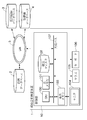
- FIG. 1 is a diagram illustrating a device configuration of the similar case retrieval apparatus according to the first embodiment.
- the similar case search apparatus 1 includes a control unit 10, a monitor 104, a mouse 105, and a keyboard 106.
- the control unit 10 includes a central processing unit (CPU) 100, a main memory 101, a magnetic disk 102, a display memory 103, and a shared bus 107.
- CPU central processing unit
- main memory 101 main memory 101
- a magnetic disk 102 a magnetic disk 102
- display memory 103 a shared bus 107.
- the CPU 100 executes the program stored in the main memory 101, various controls such as access to the case database 2, the medical image database 3, and the medical record database 4 and the overall control of the similar case search apparatus 1 are performed. Executed.
- the CPU 100 mainly controls the operation of each component of the similar case retrieval apparatus 1.
- the main memory 101 stores a control program executed by the CPU 100 and provides a work area when the CPU 100 executes the program.
- the magnetic disk 102 stores an operating system (OS), device drivers for peripheral devices, various application software including a program for performing similar case search processing, which will be described later, and work data generated or used by the software. To do.
- the display memory 103 temporarily stores display data for the monitor 104.
- the monitor 104 is, for example, a CRT monitor or a liquid crystal monitor, and displays an image based on data from the display memory 103.
- the mouse 105 and the keyboard 106 are used by the user for pointing input and character input, respectively.
- the above components are connected to each other via a shared bus 107 so that they can communicate with each other.
- the similar case retrieval apparatus 1 can read case data from the case database 2, image data from the medical image database 3, and medical record data from the medical record database 4 via the LAN 5.
- the case database 2 functions as case data storage means for storing a plurality of case data (confirmed case data) including medical image data and definitive diagnosis information corresponding to the medical image data.
- An existing PACS can be used as the medical image database 3.
- An electronic medical record system which is an existing HIS subsystem, can be used as the medical record database 4.
- an external storage device such as an FDD, HDD, CD drive, DVD drive, MO drive, ZIP drive or the like is connected to the similar case retrieval device 1 so that confirmed case data, image data, and medical record data are read from these drives. You may comprise.
- the types of medical images include simple X-ray images (X-ray images), X-ray CT (ComputedutTomography) images, MRI (Magnetic Resonance Imaging) images, PET (Positron Emission Tomography) images, and SPECT (Single Photon Emission Computed Tomography). ) Images, ultrasound images, etc.
- the medical record includes the patient's personal information (name, date of birth, age, sex, etc.), clinical information (various test values, chief complaints, medical history, treatment history, etc.), and patient information stored in the medical image database 3 Reference information to the image data and findings information of the attending physician are described. Furthermore, at the stage where the diagnosis has progressed, the final diagnosis name is written in the medical record.
- Case data stored in the case database 2 is created by copying or referring to medical record data with a definitive diagnosis name stored in the medical record database 4 and a part of image data stored in the medical image database 3. Is done.
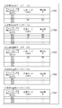
- FIGS. 10A-B show examples of case data tables stored in the case database 2.
- FIG. The case data table is a collection of data in which a plurality of case data composed of the same components are regularly arranged.
- case data ID is an identifier for uniquely identifying case data.
- the DID is given a sequential number in the order in which case data is added.
- the “definite diagnosis name” is obtained by copying the definitive diagnosis name described in the medical record data. Note that the “definite diagnosis name” is not necessarily a character string, and a standardized diagnosis code (determined diagnosis name uniquely associated with a numerical value) may be used.
- Diagnostic group ID is an identifier for uniquely identifying a diagnostic group.
- the diagnosis group is a collection of a plurality of definitive diagnosis names that do not need to be identified when performing image diagnosis.
- diseases such as lung cancer, pneumonia, and tuberculosis are known as diseases that are seen in the lungs. However, these are all treated differently, and thus need to be identified in diagnostic imaging. .
- lung adenocarcinoma, lung squamous cell carcinoma, and small cell lung cancer are all diagnoses of lung cancer in more detail, and are difficult to identify and do not need to be identified for diagnostic imaging. Classify into: In order to determine a diagnostic group, medical knowledge related to diagnostic imaging is required.
- FIG. 13 is a diagram showing an example of a correspondence table between a plurality of “final diagnosis names” and “diagnosis group IDs (GIDs)”.
- a specific definitive diagnosis name is not described in FIG.
- the correspondence table illustrated in FIG. 13 is stored in the magnetic disk 102 of the similar case retrieval apparatus 1 so that the correspondence table can be rewritten as necessary.
- the correspondence table is rewritten by a person having a predetermined authority according to a predetermined procedure.
- the rewriting of the correspondence table is performed by a person having a predetermined authority reading a new correspondence table from an external storage device (not shown) or receiving it via the LAN 5 and storing it on the magnetic disk 102.
- “reference information to medical record data” is reference information for reading medical record data corresponding to case data from the medical record database 4.
- Both “image shooting date” and “image type” can be read from medical record data or header information of image data.
- “Target organ” is information indicating in which organ a region of interest of an image to be described later is included, and is input by a doctor when creating case data.
- Reference information to image data is reference information for reading image data corresponding to case data from the medical image database 3.
- reference information to the image data instead of copying the image data itself in the case data, the size of the case data table can be reduced, and the storage capacity can be saved.
- the “interest slice number” is information necessary when the type of medical image is an image composed of a plurality of slices such as a CT image, an MRI image, or a PET image, and the most noticeable region (region of interest) in image diagnosis is It shows what slice image is included.
- the “region of interest coordinate information (X0, Y0, X1, Y1)” is information indicating in which XY coordinate range the region of interest is included in the slice image indicated by the “interest slice number”. Normally, coordinate information is expressed as position information in units of pixels in an orthogonal coordinate system in which the upper left of the image is the origin, the right direction is the X coordinate axis direction, and the lower direction is the Y coordinate axis direction.
- the coordinate information (X0, Y0, X1, Y1) represents the coordinates (X0, Y0) of the upper left corner of the region of interest and the lower right coordinates (X1, Y1) of the region of interest.
- the region of interest is obtained as follows, for example. First, image data corresponding to case data is read from the medical image database 3 using the above-mentioned “reference information to image data”. Next, a slice image designated by the “interest slice number” is selected. Finally, the image data of the region of interest can be obtained by extracting the image data within the range specified by the “coordinate information (X0, Y0, X1, Y1) of the region of interest”.
- Image feature information F of the region of interest is information representing the feature of the image data of the region of interest.
- F is multidimensional information (vector information) composed of a plurality of image feature quantities (f1, f2, f3,). Specific examples of individual image feature amounts are illustrated below.
- ⁇ Size of affected area (long diameter / short type / average diameter, area, etc.)
- the length of the contour of the affected area The shape of the affected area (the ratio between the long shape and the minor diameter, the ratio between the length of the contour and the average diameter, the fractal dimension of the contour, the degree of agreement with a plurality of predetermined model shapes Such) -Average density value of affected area-Concentration distribution pattern of affected area
- various image feature quantities can be calculated in addition to these.
- the case data table 1000 is a diagram illustrating another example of a case data table having components different from the case data table 900. “Case data ID (DID)”, “final diagnosis name”, and “diagnostic group ID (GID)” are all the same as those in the case data table 900.
- Predetermined clinical information C is obtained by selectively copying necessary clinical information from the medical record data stored in the medical record database 4.
- C is multidimensional information (vector information) composed of a plurality of clinical information (c1, c2, c3,). Specific examples of individual clinical information include various test values (physical test values, blood test values, test values related to specific diseases such as cancer markers and inflammation markers), medical history, and treatment history. is there.
- the combination of clinical information that represents C is important in calculating the similarity of clinical information. The method of determining an appropriate C depends largely on the organ to be diagnosed and the type of disease.
- the “region of interest image data I” is obtained by selecting a slice image of interest from image data stored in the medical image database 3 and further copying image data included in the region of interest in the slice image of interest. That is, I is multidimensional information (vector information) including pixel information (i1, i2, i3,...) For the number of pixels included in the region of interest.
- the “region of interest image feature information F” is the same as the case data table 900.
- case data table 900 The main difference between the case data table 900 and the case data table 1000 is whether it is stored indirectly as reference information to the clinical information C and the image data I (case data table 900) or directly (case data). Table 1000).
- all data may be stored directly in the case data table. This is because a single data read process is sufficient to read data stored in one database.
- a plurality of data reading processes are required, and the processing procedure and the processing time are increased accordingly.
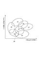
- FIG. 2 is a diagram showing a conceptual relationship between an image feature amount of a region of interest and a diagnosis group in a similar case search.
- the image feature information F of the region of interest is defined by the image feature amount 1 (f1) and the image feature amount 2 (f2).
- F is defined from about 10 to several tens of image feature amounts.
- an image feature space (multidimensional vector space) represented by F is expressed in two-dimensional XY coordinates. Expressed by space.
- the range of the diagnosis group is expressed only by the image feature information F.
- the case data includes predetermined clinical information C, both the image feature information F and the predetermined clinical information C are used.
- the range of the diagnosis group may be expressed by a higher-order multidimensional vector space.
- the similarity between unidentified case data, which will be described later, and case data with a definite diagnosis name is defined using both the image feature information F and the predetermined clinical information C.
- each diagnosis group indicates a range (limit) in which case data belonging to each diagnosis group is distributed. Even in different types of diseases belonging to different diagnosis groups, image feature information may be very similar to each other, and there is a range in which a plurality of diagnosis groups partially overlap.
- the unconfirmed case data D0 has image feature information F0 corresponding to the position indicated by the “x” mark.
- the similar case search results include at least a plurality of confirmed diagnosis names belonging to the diagnosis groups G2, G3, and G4. Additional case data is expected to be displayed.
- the execution status and execution result of the program executed by the CPU 100 are displayed on the monitor 104 by the functions of the OS and the display program separately executed by the CPU 100. Further, it is assumed that the case database 2 stores the case data table 1000 illustrated in FIGS. 10A and 10B.
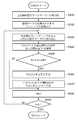
- FIG. 3 is a process flowchart of the similar case search apparatus according to the first embodiment.
- step S310 according to the command input of the user (doctor), the CPU 100 executes input reception of the unconfirmed case data D0.
- unconfirmed case data D0 is read into the main memory 101 via the shared bus 107 and the LAN 5 from the medical image database 3 or a medical image photographing apparatus (not shown).
- the CPU 100 may read unconfirmed case data D0 into the main memory 101 via the shared bus 107 from the magnetic disk 102 or an external storage device (not shown).
- the unconfirmed case data D0 includes only information related to image data.
- the unconfirmed case data D0 includes the image capturing date, the image type, the target organ, the image data I0 of the region of interest, and the image feature information F0 of the region of interest, but does not include the predetermined clinical information C0. Therefore, the similar case search process is almost the same as the similar image search process.
- the uncertain case data D0 may include predetermined clinical information C0 obtained from various clinical test results and the like. The case where the predetermined clinical information C0 is included or not included in the indeterminate case data D0 differs only in whether C0 is included or not included in the calculation of similarity, and there is no difference in the basic processing procedure.
- the CPU 100 determines similar case search conditions in accordance with a doctor's command input.
- the similar case search condition is a condition for limiting case data to be subjected to the similar case search. Specifically, it is similar only when “image type” and “target organ” that are constituent elements of case data match “image type” and “target organ” that are constituent elements of unconfirmed case data D0. Target case search. Because, in general, when these components are different, the image feature information F of the region of interest is often greatly different, and therefore case data having different components is excluded from the search target from the beginning. However, this is because the work efficiency is good. However, in preparation for similar case search from case data with different “image type” and / or “target organ”, the determination of similar case search conditions can be changed flexibly according to doctor's command input It is preferable to configure.
- step S330 the CPU 100 creates the search case data table illustrated in FIG. 11 on the main memory 101 in accordance with the similar case search condition determined in step S320.
- a case data table for search is created on the magnetic disk 102, and control is performed so that only necessary data is read out in the main memory 101 in the processing described later. May be. A method for creating the search case data table will be described later.
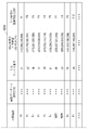
- FIG. 11 is an example of a search case data table.
- “Case data second ID (D′ ID)” is an identifier for uniquely identifying case data in the search case data table. D'ID is assigned a sequential number in order from the top row when sorting of the search case data table, which will be described later, is completed.
- “Case data ID (DID)”, “diagnostic group ID (GID)”, and “image feature information F of the region of interest” are the same as those already described in the case data tables 900 and 1000.
- “Similarity R” means the similarity between unconfirmed case data D0 and each case data (D′ 1, D′ 2, D′ 3,...) In the search case data table. At the time of S330, the similarity R has not been calculated yet.
- the CPU 100 reads case data that matches the similar case search condition from the case database 2 via the shared bus 107 and the LAN 5.
- the similar case search condition is limited to case data in which “image type” is a contrast CT image and “target organ” is lung. Accordingly, in FIG. 11, only the case data in which “image type” is a contrast CT image and “target organ” is lung among the case data shown in the case data table 1000 is read.
- the CPU 100 requires constituent elements (“case data ID (DID)”, “diagnostic group ID (GID)”, and “image feature information F of the region of interest”) for the search case data table.
- the CPU 100 sorts each row in the search case data table based on the diagnosis group ID (GID) for the purpose of speeding up a process in step S370 described later.
- FIG. 11 illustrates the result of sorting so that the diagnosis group ID (GID) is in ascending order.
- sequential numbers are assigned to “case data second ID (D′ ID)” in order from the top row.
- step S340 the CPU 100 selects upper similar case data (T1, T2,..., Tm) from the search case data table illustrated in FIG.
- the upper similar case data is the m-th case data (T1) from the top when all the case data in the search case data table are arranged in descending order of similarity to the unconfirmed case data D0. , T2,..., Tm).
- the value m (number of upper similar case data) needs to be set in advance.
- An initial value of m is written in advance in a read-only memory or a non-volatile memory (not shown) of the control unit 10.
- step S340 the value m can be changed by the CPU 100 writing the value m in a non-illustrated non-volatile memory in accordance with a doctor's command input.
- the detailed processing procedure of step S340 will be described below with reference to FIG. 4, FIG. 11, and FIG.
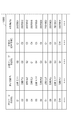
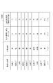
- FIG. 12 is a diagram illustrating an example of the upper similar case data table created by executing step S340 on the search case data table illustrated in FIG.
- the upper similar case data table is a table in which the upper similar case data selected by the CPU 100 in step S340 is stored on the main memory 101 in a table format.
- the value m (the number of upper similar case data) is set to the value 3.
- the upper similar case data table of FIG. 12 is composed of three rows (T1, T2, T3).
- “Upper similar case data ID (TID)” is an identifier for uniquely identifying upper similar case data. After the selection of upper similar case data in step S340 is completed, sequential numbers are assigned to TIDs in order from the top row.
- “Case data second ID (D′ ID)”, “diagnostic group ID (GID)”, and “similarity R” are the same as those already described with reference to FIG. 11, and from the search case data table (FIG. 11). make a copy.
- the case data of D′ 5, D′ 3, and D′ 6 are selected as the upper similar case data among the case data of FIG.
- Each row of the table of FIG. 12 is sorted so that the value of “similarity R” is in ascending order, and therefore there is a relationship of value R5 ⁇ value R3 ⁇ value R6.
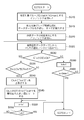
- FIG. 4 is a flowchart showing a detailed processing procedure of step S340.
- step S410 the CPU 100 creates the upper similar case data table illustrated in FIG. 12 on the main memory 101, and initializes all the components of the upper similar case data table with the value 0.
- value m value 3
- value 0 is assigned to all the constituent elements.
- step S420 the CPU 100 examines the total number of case data (number of rows in the search case data table) value N included in the search case data table illustrated in FIG. 11 and stores this value N in the main memory 101.
- the CPU 100 assigns an initial value 1 to an index variable n indicating which line in the search case data table illustrated in FIG. 11 is focused, and stores the index variable n in the main memory 101.
- step S430 the CPU 100 reads the case data D′ n in the n-th row from the search case data table illustrated in FIG.
- step S440 CPU 100 calculates similarity Rn between unconfirmed case data D0 read in step S310 and case data D'n read in step S430. Further, the CPU 100 stores the similarity Rn by writing it in the “similarity R” column in the nth row of the search case data table stored in the main memory 101.
- the calculation method of the similarity Rn any calculation method can be defined as long as the information included in both the indeterminate case data D0 and the case data D′ n is used.
- Formula (1) shows an example of a calculation formula for the similarity Rn between the image feature information F0 of the region of interest of the unconfirmed case data D0 and the image feature information Fn of the region of interest of the case data D′ n.
- the calculation method of similarity Rn is not limited to Formula (1).
- the expression (1) is expressed geometrically, it can be said to be the reciprocal of the Euclidean distance between the F0 vector and the Fn vector. Since the similarity Rn should take a larger value as the distance between the vectors is shorter, the reciprocal of the distance between the vectors is used. However, in order to reduce the amount of calculation, the difference R′n is expressed by Equation (2) instead of the similarity Rn. You may calculate. Alternatively, in order to further reduce the amount of calculation, the dissimilarity R ′′ n may be calculated by the formula (3). When the dissimilarity R′n or R ′′ n is calculated instead of the similarity Rn, it will be described later. As described above, the determination method in step S450 is changed. Moreover, since it is the same as step S450, description is abbreviate
- step S450 the CPU 100 compares the similarity Rn calculated in step S440 with the similarity R of the upper similar case data Tm (T3 in the example of FIG. 12) in the last row in the upper similar case data table. If the value Rn is equal to or greater than the R value of Tm, it is necessary to replace the upper similar case data, and the process proceeds to step S460. On the other hand, when the value Rn is less than the R value of Tm, it is not necessary to replace the upper similar case data, so the process proceeds to step S480.
- step S450 determines whether the difference R′n or R ′′ n is calculated instead of the similarity Rn in step S440.
- the value R′n or the value R ′′ n is If it is less than the R ′ value or the R ′′ value of Tm, it is necessary to replace the upper similar case data, so the process proceeds to Step S460.
- the value R′n or the value R ′′ n is the R ′ value of Tm or If it is equal to or greater than the R ′′ value, it is not necessary to replace the upper similar case data, and the process proceeds to step S480.
- step S460 the CPU 100 overwrites the three components of the case data D′ n read out in step S430 on the row of Tm (T3 in the example of FIG. 12) of the upper similar case data table.
- the three components are a “case data second ID (D′ ID)” value D′ n, a “diagnostic group ID (GID)” value, and a “similarity R” value.
- step S470 the CPU 100 sorts all rows (from T1 to Tm) in the upper similar case data table so that the value of “similarity R” is in ascending order.
- step S480 the CPU 100 increments (adds 1) the index variable n.
- step S490 the CPU 100 compares the index variable n with the number N of rows in the search case data table. If the value n is greater than the value N, all the case data in the search case data table has already been read, and the process of step S340 is terminated. Conversely, when the value n is equal to or less than the value N, all the case data in the search case data table has not been read yet, so the process returns to step S430 and continues.
- the contents of the upper similar case data table (FIG. 12) are obtained by executing the above-described step S340 on the contents of the search case data table (FIG. 11).
- step S350 the CPU 100 examines the upper similar diagnosis group IDs and their related group IDs, and determines a combination of these IDs as a search target group ID.
- the processing procedure at this time will be described in detail below with reference to FIGS.
- the CPU 100 checks the values in the “diagnostic group ID (GID)” column of the upper similar case data table illustrated in FIG. 12 over all rows. All the found GID values (value G3 and value G4 in the example of FIG. 12) are stored in the main memory 101 as higher similarity diagnosis group IDs.
- the CPU 100 refers to the correspondence table between the “diagnostic group ID (GID)” illustrated in FIG. 14 and a plurality of “related group IDs”, and examines all the related group IDs for the above-described upper similar diagnostic group IDs. These related group IDs are stored in the main memory 101. At this time, a related group ID (duplicate related group ID) related to a plurality of upper similar diagnosis group IDs and a related group ID (single related group ID) related only to one upper similar diagnosis group ID are stored separately. Keep it.
- the value G2 that is the related group ID for both the value G3 and the value G4 that are the upper similar diagnosis group ID is the duplicate related group ID, and the value G6 that is the related group ID only for the value G3.
- the value G7 is a single related group ID.
- the CPU 100 processes a combination of the above-mentioned upper similar diagnosis group ID and the related group ID as a search target group ID.
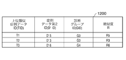
- step S360 the CPU 100 determines a lower limit value and an upper limit value for the number of selected similar case data for each search target group ID. That is, an extraction criterion is set for each group.
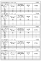
- FIG. 15 is an example of a correspondence table between “search target group ID” and “selected number (lower limit, upper limit)” of similar case data.
- the contents illustrated in FIG. 15 correspond to the contents illustrated in FIGS. 12 and 14.
- the CPU 100 examines the total number of search target group IDs (the higher similar diagnosis group IDs and their related group IDs) stored in the main memory in step S350, and has the same number of rows as this total number.
- the correspondence table illustrated in is created.
- the “search target group ID” column of the correspondence table illustrated in FIG. 15 the CPU 100 sequentially selects the upper similar diagnosis group ID (value G3, value G4) and the duplicate related group ID (value) from the top row. G2) and the single related group ID (value G6, value G7) are written.
- the CPU 100 writes the lower limit value and the upper limit value of the selection number of similar case data in the “Selection number (lower limit, upper limit)” column of the correspondence table illustrated in FIG. 15 based on the following rules.
- the number of selections uses a predetermined value for each of the upper similar diagnosis group ID, the duplicate related group ID, and the single related group ID.
- the calculation is performed based on the following rules.
- a predetermined lower limit value (value 3) is used.
- the lower limit value of the number of selections for the duplicate related group ID (G2) is a value (value 2) that is 1 smaller than the lower limit value of the selection number of the upper similar diagnosis group ID.
- the lower limit value of the selection number for the single related group ID (G6 and G7) is a value (value 1) that is 1 smaller than the lower limit value of the selection number of the duplicate related group ID.
- the number of similar cases displayed as a similar case search result can be changed by making it possible to change a predetermined value by a command input from a doctor.
- various methods of determining the number of selections (lower limit, upper limit) can be considered, but what type of determination is appropriate depends on the preference of the doctor who is the user or the window size for displaying similar case search results, etc. Different. Therefore, a plurality of selection methods (lower limit, upper limit) may be prepared in advance, and the selection method (lower limit, upper limit) may be changed by command input from a doctor.
- the lower limit value and the upper limit value of the number of selected similar case data are determined, but it is not always necessary to determine both the lower limit value and the upper limit value.
- the number of selections of similar case data may be determined one by one for each search target group ID without having a range. In this case, determining the number of selections one by one is equivalent to making the lower limit value and the upper limit value of the selection numbers equal to each other. Therefore, the processing procedure when the number of selections is determined one by one is included in the processing procedure when the lower limit value and the upper limit value of the selection number are determined.
- step S370 the CPU 100 selects similar case data for each search target group ID.
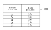
- the detailed processing procedure of step S370 will be described below with reference to FIG. 5, FIG. 16, and FIG.
- FIG. 16 is a table in which the correspondence table between “search target group ID” illustrated in FIG. 15 and “selected number (lower limit, upper limit)” of similar case data is sorted so that “search target group ID” is in ascending order. It is. By this sorting, the detailed processing procedure of step S370 described below can be simplified.
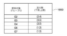
- FIG. 17 is an example of a similar case data table for each search target group.
- FIG. 5 is a detailed flowchart of step S370.
- step S510 the CPU 100 checks the value of “search target group ID” in the last row of the correspondence table illustrated in FIG. 16, and stores this value in the main memory 101 as the maximum value Gmax of “search target group ID”. .
- the CPU 100 assigns an initial value 1 to an index variable k indicating which row of the sorted correspondence table illustrated in FIG. 16 is focused, and stores this value k in the main memory 101.
- step S515 the CPU 100 creates a similar case data table for each search target group illustrated in FIG. 17 on the main memory 101 with reference to the correspondence table illustrated in FIG. Initialize with.
- the procedure for creating the similar case data table for each search target group will be described in detail with reference to the examples of FIGS. 16 and 17.
- the CPU 100 creates a similar case data table for each search target group by processing each row in FIG. 16 one by one. First, the CPU 100 reads the value G2 of the “search target group ID” and the value (2, 4) of the “selected number (lower limit, upper limit)” on the first line, and the number of lines (four lines) equal to the upper limit value of the selected number. A similar case data table for G2 is created, and all the components of the table are initialized with the value 0. The CPU 100 creates the similar case data table for each search target group exemplified in FIG. 17 by processing the second and subsequent lines in FIG. 16 in the same manner.
- step S520 the CPU 100 checks the total number of case data (number of rows in the search case data table) N included in the search case data table illustrated in FIG. 11 and stores this value N in the main memory 101. Since the value N has already been stored in the main memory 101 in step S420 in FIG. 4, if the value N is stored even after the process in FIG. 4 (the process in step S340) is completed, the value N is again in step S520. There is no need to memorize. Next, the CPU 100 assigns an initial value 1 to an index variable n indicating which line in the search case data table illustrated in FIG. 11 is focused, and stores this value n in the main memory 101.
- step S525 the CPU 100 reads out the case data D′ n in the n-th row from the search case data table illustrated in FIG.
- step S530 the CPU 100 compares the value of the diagnosis group ID (GID) included in the case data D′ n read out in step S525 with a value Gk described below. If the comparison results are equal, the process proceeds to step S535. Conversely, if the comparison results are not equal, the process proceeds to step S560.
- GID diagnosis group ID
- the suffix k of the value Gk is the index variable k described in step S510.
- step S560 Since G1 ⁇ G2, after step S530 is first executed, the process proceeds to step S560.
- the process only when the value of the diagnosis group ID (GID) possessed by the case data matches the value of any of the search target group IDs exemplified in FIG. 16 among the case data exemplified in FIG. The process proceeds to step S535. Thereby, only the case data belonging to the search target group can be set as a target for similar case search.
- GID diagnosis group ID
- step S535 the CPU 100 compares two “similarity R” values.
- the value of “similarity R” is the value Rn of “similarity R” included in the case data D′ n read out in step S525.
- the other value of “similarity R” is the value of “similarity R” in the last row GTm of the similar case data table for Gk illustrated in FIG. 17 (abbreviated as R value of GTm for Gk). If the value Rn is equal to or greater than the R value of the Gk GTm, the content of the similar case data table for Gk needs to be updated, and the process proceeds to step S540. Conversely, if the value Rn is less than the R value of the Gk GTm, the process proceeds to step S550.
- step S540 the CPU 100 adds the “case data ID (DID)” value Dn and “similarity” of the case data D′ n read in step S525 to the last row GTm of the similar case data table for Gk illustrated in FIG. Overwrite the value Rn of R ′′.
- DID case data ID
- step S545 the CPU 100 sorts all rows (from GT1 to GTm) of the similar case data table for Gk so that the “similarity R” is in ascending order. Thereby, in the similar case data table for Gk, “similarity R” of GTm becomes the smallest value.
- step S550 the CPU 100 adds 1 to the index variable n.
- step S555 the CPU 100 compares the index variable n with the value N (the number of rows in the search case data table illustrated in FIG. 11). If the index variable n is greater than the value N, the process of step S370 ends. Conversely, if the index variable n is less than or equal to the value N, the process returns to step S525 and continues.
- step S560 the CPU 100 adds 1 to the index variable k.
- step S370 instead of simply thresholding the similarity between the unconfirmed case data and the confirmed case data and selecting the similar case data, They are arranged in descending order, and a predetermined number is selected from the top. If the similarity is simply thresholded and similar case data is selected, the following problem occurs. That is, when the number of case data stored in the case database 2 increases, the number of case data having a high degree of similarity increases. Accordingly, the number of selected similar case data will increase unless the similarity threshold is changed. That is, when a similar case search is performed by the threshold processing of the similarity, the similar case search result varies depending on the number of case data stored in the case database 2. On the other hand, the processing procedure in the first embodiment is not affected by the size variation of the case database 2, and therefore has an advantage that a certain number of similar case data by diagnosis group can always be searched.
- step S380 the CPU 100 refers to the contents of the similar case data table classified by diagnosis group created in step S370 and displays similar case data by grouping for each diagnosis group.
- the processing procedure when the CPU 100 reads similar case data for each search target group will be described in detail below using the specific examples of FIGS. 15 and 17.
- CPU 100 reads the value of “search target group ID” in the correspondence table illustrated in FIG. 15 in order from the first row. Then, the similar case data table corresponding to the read “search target group ID” value is selected from the similar case data table for each search target group illustrated in FIG. Specifically, first, the value G3 is read from the first row of the correspondence table in FIG. 15, and then the similar case data table for G3 in FIG. 17 is selected.
- the CPU 100 sequentially reads the value of “case data ID (DID)” in the similar case data table for G3 in FIG. 17 from the first row, and displays the case data corresponding to the read DID value as shown in FIG. B or the case data table illustrated in FIGS. 10A-B.
- the “definite diagnosis name”, “predetermined clinical information C”, and “image data I of the region of interest” included in D9 are extracted to obtain the first G3 data. Similar case data with a definitive diagnosis name can be obtained. Similar case data with other definitive diagnosis names can be obtained in the same procedure.
- the “definite diagnosis name” can be directly extracted, but predetermined clinical information and image data of the region of interest must be read from the medical record database 4 and the medical image database 3, respectively. is there.
- predetermined clinical information first, “reference information to medical record data” included in D9 read from the case data table 900 is extracted.
- medical record data referred to by the reference information is read from the medical record database 4.
- predetermined clinical information is extracted from the medical record data.
- image data of the region of interest first, “reference information to the image data” included in D9 read from the case data table 900 is extracted.
- the image data referred to by the reference information is read from the medical image database 3.
- interest slice number and “coordinate information (X0, Y0, X1, Y1) of the region of interest” included in D9 read from the case data table 900 are extracted. Then, by using these pieces of information and specifying the interest slice number and the region of interest of the image data read from the medical image database 3, the image data of the region of interest can be obtained.
- 5 cases, 5 cases, 4 cases, 3 cases, and 3 cases are assigned with a definite diagnosis name for each search target group of G3, G4, G2, G6, and G7. Similar case data will be obtained. That is, a predetermined number or more of confirmed case data similar to each group is extracted.
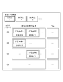
- FIG. 7 is an example of a screen displayed as a result of the processing in step S380.
- a part of the image data being diagnosed is displayed at the top of FIG.
- Each of these images is obtained by cutting out a region of interest from image data being diagnosed by a doctor.
- the “new image 1” may be an image obtained by cutting out a region of interest surrounding an abnormal shadow that appears in a part of a lung field region of a chest CT image.
- the doctor selects an image written as “new image 1” and inputs a command for instructing execution of similar case search
- the result of the above processing displays the similar case search result in a portion below the boundary line of the screen. Is done.
- the similar case retrieval apparatus it is possible to extract a plurality of confirmed case data having different diagnosis results from the case database 2 for the input unconfirmed case data. . Accordingly, the user (doctor) can examine a plurality of diagnosis results that may correspond to the input case data based on the diagnosis results of the extracted plurality of confirmed case data.
- the process in step S510 is the same as the process in the first embodiment.
- the process in step S515 is substantially the same as the process in the first embodiment, but instead of the similar case data table classified by search target group illustrated in FIG. 17, the similar case data table classified by search target group illustrated in FIG. Different points to create.
- FIG. 18 shows another example of the similar case data table for each search target group.
- the similar case data table for Gk illustrated in FIG. 18 is obtained by adding two columns of information described later to the similar case data table for Gk illustrated in FIG.
- the added first column is “image feature information F of the region of interest”, and the added second column is “duplicate”.
- step S515 the CPU 100 creates the similar case data table for each search target group illustrated in FIG. 18 on the main memory 101, and initializes all the components of all the tables with the value 0.
- step S520 to step S535 and the processing from step S550 to step S565 are the same as the processing in the first embodiment, description thereof will be omitted.
- step S540 and step S545 of FIG. 5 are not executed, and instead, steps S610 to S690 shown in the flowchart of FIG. 6 are executed.
- FIG. 6 is a flowchart showing a processing procedure according to the second embodiment.
- step S610 the CPU 100 checks the number m of rows in the similar case data table for Gk illustrated in FIG. 18 and stores this value m in the main memory 101. Further, the CPU 100 assigns an initial value 1 to an index variable i indicating which line in the similar case data table for Gk illustrated in FIG. 18 is focused, and stores the index variable i in the main memory 101.
- Gk in the above-mentioned similar case data table for Gk is the value of “search target group ID” illustrated in FIG.
- the subscript k of Gk is an index variable indicating which line in the sorted correspondence table illustrated in FIG. 16 is focused as described in step S510 of FIG.
- step S620 the CPU 100 reads the i-th case data GTi from the Gk similar case data table illustrated in FIG.
- step S630 the CPU 100 calculates a similarity GkRi between the case data D′ n read in step S525 of FIG. 5 and the GTi read in step S620.
- the method of calculating similarity GkRi is the same as the method of calculating similarity Rn described in step S440 of FIG. That is, if the image feature information of the region of interest in the case data D′ n is Fn and the image feature information of the region of interest in the case data GTi is Fi, the similarity GkRi can be calculated using Expression (4).
- the difference degree GkR′i or GkR ′′ i may be calculated using the equation (5) or (6) instead of the similarity degree GkRi.
- the determination method in step S640 described later is also changed.
- step S640 the CPU 100 compares the similarity GkRi calculated in step S630 with a predetermined threshold value.
- the predetermined threshold value is a threshold value for determining whether two case data belonging to the same diagnosis group are very similar. If the similarity GkRi is greater than or equal to the predetermined threshold (case data D′ n and GTi are very similar), the process proceeds to step S650. Conversely, if the similarity GkRi is less than the predetermined threshold (case data D′ n and GTi are not very similar), the process proceeds to step S660.
- step S640 When the difference degree GkR′i or GkR ′′ i is calculated in step S630 instead of the similarity degree GkRi, the determination method in step S640 is changed as follows.
- the difference degree GkR′i or GkR ′′ i is changed as follows. If it is less than the predetermined threshold, the process proceeds to step S650. On the other hand, if the degree of difference GkR′i or GkR ′′ i is greater than or equal to a predetermined threshold, the process proceeds to step S660.
- step S650 the CPU 100 adds 1 to the “duplicate” of the case data GTi, and then writes it in the “duplicate” column in the i-th row of the similar case data table for Gk illustrated in FIG. Then, the process of FIG. 6 is complete
- step S660 the CPU 100 adds 1 to the index variable i.
- step S670 CPU 100 compares index variable i with value m checked in step S610. If i is larger than m, the process proceeds to step S680. If i is equal to or smaller than m, the process returns to step S620.
- step S680 the CPU 100 sets three case data D′ n read out in step S525 in FIG. 5 in the last row GTm (GT4 in the example of the similar case data table for G2 in FIG. 18) of the similar case data table for Gk.
- Overwrite components That is, at the stage of proceeding to step S680, the CPU 100 stores similar case data very similar to the case data D′ n read out in step S525 in FIG. 5 in the similar case data table for Gk illustrated in FIG. This is because it has been confirmed that there is no.
- the three components to be overwritten are the value Dn of “case data ID (DID)”, the value Fn of “image feature information F of the region of interest”, and the value Rn of “similarity R”.
- DID case data ID
- Fn image feature information
- Rn similarity R
- step S690 the CPU 100 sorts all rows (from GT1 to GTm) in the similar case data table for Gk so that the value of “similarity R” is in ascending order. Then, the process of FIG. 6 is complete
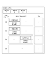
- FIG. 8 is an example of a screen displayed as a result of the process in step S380 of FIG. 3 according to the second embodiment.
- Most of the screen examples illustrated in FIG. 8 are the same as the screen example illustrated in FIG.
- each similar case data displayed as the similar case search result by diagnosis group is displayed.
- the “duplicate” of similar case data belonging to the same diagnosis group calculated in step S650 of FIG. 6 is displayed together with the image data and the definitive diagnosis name.
- the doctor who performs the image diagnosis can know how frequently each similar case data is the case data that appears in the case database 2 by looking at “duplicate”.
- other information (such as a graph) derived from the overlap number may be displayed instead of the above-described “overlap number”.
- the similar case retrieval apparatus it is possible to extract a plurality of confirmed case data having different diagnosis results from the case database 2 for the input unconfirmed case data. .
- the present invention can also be realized by executing the following processing. That is, software (program) that realizes the functions of the above-described embodiments is supplied to a system or apparatus via a network or various storage media, and the computer (or CPU, MPU, etc.) of the system or apparatus reads the program. It is a process to be executed.
Landscapes
- Engineering & Computer Science (AREA)
- Health & Medical Sciences (AREA)
- Public Health (AREA)
- Medical Informatics (AREA)
- Data Mining & Analysis (AREA)
- Primary Health Care (AREA)
- Epidemiology (AREA)
- General Health & Medical Sciences (AREA)
- Databases & Information Systems (AREA)
- Theoretical Computer Science (AREA)
- Library & Information Science (AREA)
- Biomedical Technology (AREA)
- Pathology (AREA)
- Physics & Mathematics (AREA)
- General Physics & Mathematics (AREA)
- General Engineering & Computer Science (AREA)
- Nuclear Medicine, Radiotherapy & Molecular Imaging (AREA)
- Radiology & Medical Imaging (AREA)
- Information Retrieval, Db Structures And Fs Structures Therefor (AREA)
- Measuring And Recording Apparatus For Diagnosis (AREA)
- Processing Or Creating Images (AREA)
- Medical Treatment And Welfare Office Work (AREA)
Abstract
Provided is a technique for extracting, from a case database, a plurality of sets of confirmed case data analogous to an inputted case.
A data search device for extracting confirmed case data from a case database comprises: an input receiving means for receiving an input of case data including at least medical image data; a derivation means for deriving a degree of similarity to the inputted case data from each of the sets of confirmed case data stored in the case database; a classification means for classifying, based on confirmed diagnosis information included in each of the sets of confirmed case data, the sets of confirmed case data stored in the case database into a plurality of diagnosis groups; and an extraction means for extracting, based on the derived degree of similarity, a predetermined number or more of sets of confirmed case data from each of the diagnosis groups.
Description
本発明は、症例データベースから類似の症例データを検索する技術に関するものである。
The present invention relates to a technique for retrieving similar case data from a case database.
近年、病院情報システム(HIS:Hospital Information System)や画像保管通信システム(PACS:Picture Archiving and Communication System)等の医用情報システムの普及に連れて、医用文書及び医用画像の電子化が進展している。これにより、以前はフィルムに現像されてからシャーカステン上で見ることが多かった医用画像(X線画像、CT画像あるいはMRI画像など)は、現在ではデジタル化されている。デジタル化された医用画像(デジタル画像)はPCASに格納され、必要な時にPACSから読み出され端末のモニタ上に表示される。また、診療記録等の医用文書も電子化されてきており、患者の診療記録をHISから読み出して端末のモニタ上に表示することも可能となってきた。さらに、電子化された環境にいる読影医は、読影の依頼箋を電子的なメッセージにより受け取り、患者を撮影した医用画像データをPACSから読み出して端末の読影専用モニタ上に表示することも出来る。また、必要に応じて患者の診療記録をHISから読み出して、別のモニタ上に表示することができる。
In recent years, with the spread of medical information systems such as hospital information systems (HIS: Hospital Information System) and image storage communication systems (PACS: Picture Architecture and Communication System), the digitization of medical documents and medical images has been progressing. . As a result, medical images (such as X-ray images, CT images, or MRI images) that were previously developed on film and often viewed on the Schaukasten are now digitized. The digitized medical image (digital image) is stored in the PCAS, read out from the PACS when necessary, and displayed on the terminal monitor. In addition, medical documents such as medical records have been digitized, and it has become possible to read a patient's medical records from the HIS and display them on a terminal monitor. Furthermore, an interpreting doctor in an electronic environment can receive an interpretation request form as an electronic message, read out medical image data obtained by imaging a patient from the PACS, and display the medical image data on a terminal dedicated monitor. In addition, patient medical records can be read from the HIS and displayed on another monitor as needed.
ところで、医師が医用画像を読影して画像診断を行う際に、読影中の画像に写った患部が見慣れない画像特徴を持つ場合や、類似した画像特徴を持つ疾患が複数存在する場合などは、診断名の判断に迷うことがある。この様な場合、迷った医師は他のベテラン医師に相談するか、または、医学書等の文献を調べて、疑わしい疾患名に関する画像特徴の解説文を読むことがある。あるいは、写真付きの医学文献を調べ、読影中の画像に写った患部と類似した写真を見つけ、その写真に対応する疾患名を見ることで、診断の参考にしようとすることがある。しかし、常に相談できる他の医師がいるとは限らない。また、文献を調べたからといって、必ず読影中の画像に写った患部と類似した写真あるいは画像特徴の解説文が見つかるとは限らない。そこで、近年、類似症例を検索する装置が提案されている。検索装置の基本的な考え方は、過去に蓄積した症例データの中から何らかの基準に基づき症例データを検索して医師に提示することにより、診断の支援をしようとするものである。
By the way, when a doctor interprets a medical image and makes an image diagnosis, if the affected part shown in the image being interpreted has an unfamiliar image feature, or if there are multiple diseases with similar image features, The diagnosis name may be lost. In such a case, the lost doctor may consult other veteran doctors, or look up documents such as medical books, and read the commentary on the image features regarding the suspicious disease name. Alternatively, the medical literature with photographs may be examined, a photograph similar to the affected area shown in the image being read is found, and the disease name corresponding to the photograph is referred to for reference of diagnosis. However, there are not always other doctors who can consult. In addition, just by examining the literature, it is not always possible to find a photo or an image feature description similar to the affected part in the image being interpreted. In recent years, an apparatus for searching for similar cases has been proposed. The basic idea of the search device is to support diagnosis by searching case data from some case data accumulated in the past and presenting it to a doctor.
例えば、特許文献1では、過去に診断された画像データを、所見と病名を含む診断情報と対応付けてデータベースに蓄積する技術が開示されている。また、新たに診断しようとする画像に対する所見が入力されると、同様の所見を含む過去の診断情報を検索し、対応する画像データや病名を表示する技術も併せて開示されている。そして、特許文献2では、診断履歴比較手段によって、画像診断結果と確定診断結果とが食い違っている参考症例(画像診断が間違っていた症例)を検出して参考症例データベースに登録する技術が開示されている。また、後から識別情報を指定することで必要な参考症例画像を参照可能な参考症例検索方式を開示している。
For example, Patent Document 1 discloses a technique for storing image data diagnosed in the past in association with diagnostic information including findings and disease names in a database. In addition, a technique is also disclosed in which when a finding on an image to be newly diagnosed is input, past diagnosis information including the same finding is searched and corresponding image data and a disease name are displayed. And in patent document 2, the technique which detects the reference case (case where image diagnosis was wrong) by which a diagnostic history comparison means and an image diagnosis result and a definite diagnosis result are inconsistent, and registers them in a reference case database is disclosed. ing. In addition, a reference case search method is disclosed in which necessary reference case images can be referred to by specifying identification information later.
しかしながら、例えば、特許文献1に記載の技術では、類似症例検索結果として画像データと病名の両方が得られるものの、文章の類似性に基づいて検索しているため必ずしも画像特徴の類似性を保障している訳ではない。また、類似した所見を持つ症例データの病名しか得られないため、複数の異なる病名が得られるとも限らない。また、特許文献2に記載の技術では、医師に対して誤診に対する注意喚起をすることはできるが、必ずしも現在読影中の画像の正しい診断名を類推させる症例データが示せる訳ではない。そのため、ある症例について過去の症例データを検索する際に、医師が判断に迷う可能性のある異なる確定診断結果を持つ複数の症例データが得られないという問題があった。
However, for example, in the technique described in Patent Document 1, although both image data and a disease name are obtained as a similar case search result, since the search is based on the similarity of sentences, the similarity of image features is not necessarily guaranteed. I don't mean. Further, since only disease names of case data having similar findings can be obtained, it is not always possible to obtain a plurality of different disease names. The technique described in Patent Document 2 can alert a doctor to misdiagnosis, but does not necessarily indicate case data for estimating the correct diagnosis name of an image currently being interpreted. Therefore, when searching past case data for a certain case, there is a problem in that a plurality of case data having different definitive diagnosis results that the doctor may be confused about cannot be obtained.
本発明は、ある症例について過去の症例データを検索する際に、異なる確定診断結果を持つ複数の症例データを抽出可能とする技術を提供する。
The present invention provides a technique that enables extraction of a plurality of case data having different definite diagnosis results when searching past case data for a certain case.
上述の問題点を解決するため、本発明のデータ検索装置は以下の構成を備える。すなわち、医用画像データと該医用画像データに対応する確定した診断情報とを含む複数の確定症例データを記憶する症例データベースから1以上の確定症例データを抽出するデータ検索装置において、少なくとも医用画像データを含む症例データの入力を受け付ける入力受付手段と、前記症例データベースに記憶された前記複数の確定症例データの各々について、前記入力受付手段により入力された前記症例データとの類似度を導出する導出手段と、前記症例データベースに記憶される前記複数の確定症例データを、該複数の確定症例データの各々に含まれる確定した診断情報に基づいて複数の診断グループに分類する分類手段と、前記複数の診断グループの各々から、前記導出手段により導出された類似度に基づいて所定数以上の確定症例データを抽出する抽出手段と、を含む。
In order to solve the above-described problems, the data search apparatus of the present invention has the following configuration. That is, in a data search apparatus that extracts one or more confirmed case data from a case database storing a plurality of confirmed case data including medical image data and confirmed diagnosis information corresponding to the medical image data, at least the medical image data is extracted. Input receiving means for receiving input of case data including, and derivation means for deriving a similarity with the case data input by the input receiving means for each of the plurality of confirmed case data stored in the case database Classifying means for classifying the plurality of confirmed case data stored in the case database into a plurality of diagnosis groups based on confirmed diagnosis information included in each of the plurality of confirmed case data; and the plurality of diagnosis groups A predetermined number or more of definite diseases based on the similarity derived by the deriving means Comprising extracting means for extracting the data.
上述の問題点を解決するため、本発明のデータ検索装置の制御方法は以下の構成を備える。すなわち、医用画像データと該医用画像データに対応する確定した診断情報とを含む複数の確定症例データを記憶する症例データベースから1以上の確定症例データを抽出するデータ検索装置の制御方法において、少なくとも医用画像データを含む症例データの入力を受け付ける入力受付工程と、前記症例データベースに記憶された前記複数の確定症例データの各々について、前記入力受付工程により入力された前記症例データとの類似度を導出する導出工程と、前記症例データベースに記憶される前記複数の確定症例データを、該複数の確定症例データの各々に含まれる確定した診断情報に基づいて複数の診断グループに分類する分類工程と、前記複数の診断グループの各々から、前記導出工程により導出された類似度に基づいて所定数以上の確定症例データを抽出する抽出工程と、を含む。
In order to solve the above-described problems, the control method of the data search apparatus of the present invention has the following configuration. That is, in a control method of a data search apparatus for extracting one or more confirmed case data from a case database storing a plurality of confirmed case data including medical image data and confirmed diagnosis information corresponding to the medical image data, at least medical An input receiving step for receiving input of case data including image data, and a degree of similarity between the case data input by the input receiving step and each of the plurality of confirmed case data stored in the case database is derived. A derivation step, a classification step of classifying the plurality of confirmed case data stored in the case database into a plurality of diagnosis groups based on confirmed diagnosis information included in each of the plurality of confirmed case data, and the plurality Based on the degree of similarity derived by the derivation step from each of the diagnostic groups, a predetermined number or more Including an extraction step of extracting a definite case data.
上述の問題点を解決するため、本発明のデータ検索システムは以下の構成を備える。すなわち、医用画像データと該医用画像データに対応する確定した診断情報とを含む複数の確定症例データを記憶する症例データベースと、該症例データベースにアクセスして1以上の確定症例データを抽出するデータ検索装置と、を含むデータ検索システムにおいて、少なくとも医用画像データを含む症例データの入力を受け付ける入力受付手段と、前記症例データベースに記憶された前記複数の確定症例データの各々について、前記入力受付手段により入力された前記症例データとの類似度を導出する導出手段と、前記症例データベースに記憶される前記複数の確定症例データを、該複数の確定症例データの各々に含まれる確定した診断情報に基づいて複数の診断グループに分類する分類手段と、前記複数の診断グループの各々から、前記導出手段により導出された類似度に基づいて所定数以上の確定症例データを抽出する抽出手段と、を含む。
In order to solve the above problems, the data search system of the present invention has the following configuration. That is, a case database storing a plurality of confirmed case data including medical image data and confirmed diagnosis information corresponding to the medical image data, and a data search for accessing the case database and extracting one or more confirmed case data An input receiving unit that receives input of case data including at least medical image data, and each of the plurality of confirmed case data stored in the case database is input by the input receiving unit. Deriving means for deriving the similarity to the case data and a plurality of the confirmed case data stored in the case database based on the confirmed diagnosis information included in each of the plurality of confirmed case data Classifying means for classifying the diagnostic group into a plurality of diagnostic groups, and from each of the plurality of diagnostic groups, Comprising extracting means for extracting a definite case data of a predetermined number or more based on the similarity derived by deriving means.
本発明によれば、ある症例について過去の症例データを検索する際に、異なる確定診断結果を持つ複数の症例データを抽出可能とする技術を提供することができる。
According to the present invention, it is possible to provide a technique capable of extracting a plurality of case data having different definite diagnosis results when searching past case data for a certain case.
本発明のその他の特徴及び利点は、添付図面を参照とした以下の説明により明らかになるであろう。なお、添付図面においては、同じ若しくは同様の構成には、同じ参照番号を付す。
Other features and advantages of the present invention will become apparent from the following description with reference to the accompanying drawings. In the accompanying drawings, the same or similar components are denoted by the same reference numerals.
添付図面は明細書に含まれ、その一部を構成し、本発明の実施の形態を示し、その記述と共に本発明の原理を説明するために用いられる。
第1実施形態に係る類似症例検索装置の機器構成を示す図である。
類似症例検索における関心領域の画像特徴量と診断グループとの関係を概念的に示す図である。
第1実施形態に係る類似症例検索装置の処理フローチャートである。
ステップS340の詳細な処理手順を示すフローチャートである。
ステップS370の詳細な処理手順を示すフローチャートである。
ステップS370の処理手順の一部の詳細手順を示すフローチャートである(第2実施形態)。
第1実施形態に係る類似症例検索装置における処理結果の表示例を示す図である。
第2実施形態に係る類似症例検索装置における処理結果の表示例を示す図である。
症例データベース2に保管される症例データテーブルの例を示す図である。
症例データベース2に保管される症例データテーブルの例を示す図である。
症例データベース2に保管される症例データテーブルの他の例を示す図である。
症例データベース2に保管される症例データテーブルの他の例を示す図である。
検索用症例データテーブルの例を示す図である。
上位類似症例データテーブルの例を示す図である。
複数の“確定診断名”と“診断グループID(GID)”との対応表の例を示す図である。
“診断グループID(GID)”と複数の“関連グループID”との対応表の例を示す図である。
“検索対象グループID”と類似症例データの“選出数(下限,上限)”との対応表の例を示す図である。
図15の対応表を、“検索対象グループID”が昇順となる様にソートした表を示す図である。
検索対象グループ別類似症例データテーブルの例を示す図である。
検索対象グループ別類似症例データテーブルの他の例を示す図である。
The accompanying drawings are included in the specification, constitute a part thereof, show an embodiment of the present invention, and are used to explain the principle of the present invention together with the description.
It is a figure which shows the apparatus structure of the similar case search apparatus which concerns on 1st Embodiment. It is a figure which shows notionally the relationship between the image feature-value of the region of interest in a similar case search, and a diagnostic group. It is a processing flowchart of the similar case search device concerning a 1st embodiment. It is a flowchart which shows the detailed process sequence of step S340. It is a flowchart which shows the detailed process sequence of step S370. It is a flowchart which shows the one part detailed procedure of the process sequence of step S370 (2nd Embodiment). It is a figure which shows the example of a display of the process result in the similar case search apparatus which concerns on 1st Embodiment. It is a figure which shows the example of a display of the process result in the similar case search apparatus which concerns on 2nd Embodiment. It is a figure which shows the example of the case data table stored in the case database. It is a figure which shows the example of the case data table stored in the case database. It is a figure which shows the other example of the case data table stored in the case database. It is a figure which shows the other example of the case data table stored in the case database. It is a figure which shows the example of the case data table for a search. It is a figure which shows the example of an upper similar case data table. It is a figure which shows the example of the corresponding | compatible table of several "confirmed diagnosis name" and "diagnosis group ID (GID)". It is a figure which shows the example of the conversion table of "diagnosis group ID (GID)" and several "related group ID". It is a figure which shows the example of the conversion table of "search target group ID" and "selection number (lower limit, upper limit)" of similar case data. FIG. 16 is a diagram showing a table in which the correspondence table of FIG. 15 is sorted so that “search target group ID” is in ascending order. It is a figure which shows the example of the similar case data table according to search object group. It is a figure which shows the other example of the similar case data table according to search object group.
以下に、図面を参照して、この発明の好適な実施の形態を詳しく説明する。なお、以下の実施の形態はあくまで例示であり、本発明の範囲を限定する趣旨のものではない。
Hereinafter, preferred embodiments of the present invention will be described in detail with reference to the drawings. The following embodiments are merely examples, and are not intended to limit the scope of the present invention.
(第1実施形態)
本発明に係るデータ検索装置の第1実施形態として、医療用データ検索システムにおける類似症例検索装置を例に挙げて以下に説明する。 (First embodiment)
As a first embodiment of the data search device according to the present invention, a similar case search device in a medical data search system will be described below as an example.
本発明に係るデータ検索装置の第1実施形態として、医療用データ検索システムにおける類似症例検索装置を例に挙げて以下に説明する。 (First embodiment)
As a first embodiment of the data search device according to the present invention, a similar case search device in a medical data search system will be described below as an example.
<装置構成>
図1は、第1実施形態に係る類似症例検索装置の機器構成を示す図である。類似症例検索装置1は、制御部10、モニタ104、マウス105、キーボード106を有する。制御部10は、中央処理装置(CPU)100、主メモリ101、磁気ディスク102、表示メモリ103、共有バス107を有する。そして、CPU100が主メモリ101に格納されたプログラムを実行することにより、症例データベース2、医用画像データベース3および診療録データベース4へのアクセス、類似症例検索装置1の全体の制御、等の各種制御が実行される。 <Device configuration>
FIG. 1 is a diagram illustrating a device configuration of the similar case retrieval apparatus according to the first embodiment. The similarcase search apparatus 1 includes a control unit 10, a monitor 104, a mouse 105, and a keyboard 106. The control unit 10 includes a central processing unit (CPU) 100, a main memory 101, a magnetic disk 102, a display memory 103, and a shared bus 107. When the CPU 100 executes the program stored in the main memory 101, various controls such as access to the case database 2, the medical image database 3, and the medical record database 4 and the overall control of the similar case search apparatus 1 are performed. Executed.
図1は、第1実施形態に係る類似症例検索装置の機器構成を示す図である。類似症例検索装置1は、制御部10、モニタ104、マウス105、キーボード106を有する。制御部10は、中央処理装置(CPU)100、主メモリ101、磁気ディスク102、表示メモリ103、共有バス107を有する。そして、CPU100が主メモリ101に格納されたプログラムを実行することにより、症例データベース2、医用画像データベース3および診療録データベース4へのアクセス、類似症例検索装置1の全体の制御、等の各種制御が実行される。 <Device configuration>
FIG. 1 is a diagram illustrating a device configuration of the similar case retrieval apparatus according to the first embodiment. The similar
CPU100は、主として類似症例検索装置1の各構成要素の動作を制御する。主メモリ101は、CPU100が実行する制御プログラムを格納したり、CPU100によるプログラム実行時の作業領域を提供したりする。磁気ディスク102は、オペレーティングシステム(OS)、周辺機器のデバイスドライバ、後述する類似症例検索処理等を行うためのプログラムを含む各種アプリケーションソフト、およびそれらのソフトが生成または使用する作業用データ等を格納する。表示メモリ103は、モニタ104のための表示用データを一時記憶する。モニタ104は、例えばCRTモニタや液晶モニタ等であり、表示メモリ103からのデータに基づいて画像を表示する。マウス105及びキーボード106はユーザによるポインティング入力及び文字等の入力をそれぞれ行う。上記各構成要素は共有バス107により互いに通信可能に接続されている。
The CPU 100 mainly controls the operation of each component of the similar case retrieval apparatus 1. The main memory 101 stores a control program executed by the CPU 100 and provides a work area when the CPU 100 executes the program. The magnetic disk 102 stores an operating system (OS), device drivers for peripheral devices, various application software including a program for performing similar case search processing, which will be described later, and work data generated or used by the software. To do. The display memory 103 temporarily stores display data for the monitor 104. The monitor 104 is, for example, a CRT monitor or a liquid crystal monitor, and displays an image based on data from the display memory 103. The mouse 105 and the keyboard 106 are used by the user for pointing input and character input, respectively. The above components are connected to each other via a shared bus 107 so that they can communicate with each other.
第1実施形態では、類似症例検索装置1はLAN5を介して、症例データベース2から症例データを、医用画像データベース3から画像データを、および診療録データベース4から診療録データを、それぞれ読み出すことができる。ここで、症例データベース2は、医用画像データとその医用画像データに対応する確定診断情報とを含む症例データ(確定症例データ)を複数保管する症例データ保管手段として機能する。そして、医用画像データベース3として既存のPACSを利用することができる。また、診療録データベース4として既存のHISのサブシステムである電子カルテシステムを利用することができる。なお、類似症例検索装置1に外部記憶装置、例えばFDD、HDD、CDドライブ、DVDドライブ、MOドライブ、ZIPドライブ等を接続し、それらのドライブから確定症例データ、画像データおよび診療録データを読み込むように構成しても良い。
In the first embodiment, the similar case retrieval apparatus 1 can read case data from the case database 2, image data from the medical image database 3, and medical record data from the medical record database 4 via the LAN 5. . Here, the case database 2 functions as case data storage means for storing a plurality of case data (confirmed case data) including medical image data and definitive diagnosis information corresponding to the medical image data. An existing PACS can be used as the medical image database 3. An electronic medical record system, which is an existing HIS subsystem, can be used as the medical record database 4. It should be noted that an external storage device such as an FDD, HDD, CD drive, DVD drive, MO drive, ZIP drive or the like is connected to the similar case retrieval device 1 so that confirmed case data, image data, and medical record data are read from these drives. You may comprise.
なお、医用画像の種類には、単純X線画像(レントゲン画像)、X線CT(Computed Tomography)画像、MRI(Magnetic Resonance Imaging)画像、PET(Positron Emission Tomography)画像、SPECT(Single Photon Emission Computed Tomography)画像、超音波画像などがある。
The types of medical images include simple X-ray images (X-ray images), X-ray CT (ComputedutTomography) images, MRI (Magnetic Resonance Imaging) images, PET (Positron Emission Tomography) images, and SPECT (Single Photon Emission Computed Tomography). ) Images, ultrasound images, etc.
診療録には、患者の個人情報(氏名、生年月日、年齢、性別など)、臨床情報(様々な検査値、主訴、既往歴、治療歴など)、医用画像データベース3に格納された患者の画像データへの参照情報および主治医の所見情報などが記載される。さらに、診断が進んだ段階で、診療録には確定診断名が記載される。
The medical record includes the patient's personal information (name, date of birth, age, sex, etc.), clinical information (various test values, chief complaints, medical history, treatment history, etc.), and patient information stored in the medical image database 3 Reference information to the image data and findings information of the attending physician are described. Furthermore, at the stage where the diagnosis has progressed, the final diagnosis name is written in the medical record.
症例データベース2に保管される症例データは、診療録データベース4に保管された確定診断名付きの診療録データおよび医用画像データベース3に保管された画像データの一部を、コピーまたは参照することにより作成される。
Case data stored in the case database 2 is created by copying or referring to medical record data with a definitive diagnosis name stored in the medical record database 4 and a part of image data stored in the medical image database 3. Is done.
<データ構造>
図9A-Bおよび図10A-Bに、症例データベース2に保管される症例データテーブルの例を示す。症例データテーブルとは、同じ構成要素から成る複数の症例データを規則正しく並べたデータの集まりである。 <Data structure>
9A-B and FIGS. 10A-B show examples of case data tables stored in thecase database 2. FIG. The case data table is a collection of data in which a plurality of case data composed of the same components are regularly arranged.
図9A-Bおよび図10A-Bに、症例データベース2に保管される症例データテーブルの例を示す。症例データテーブルとは、同じ構成要素から成る複数の症例データを規則正しく並べたデータの集まりである。 <Data structure>
9A-B and FIGS. 10A-B show examples of case data tables stored in the
症例データの構成要素は以下の意味を持つ。“症例データID(DID)”は、症例データを一意に識別するための識別子である。DIDには、症例データが追加された順番にシーケンシャルな番号を付ける。“確定診断名”は、診療録データに記載された確定診断名をコピーすることで得られる。なお、“確定診断名”は必ずしも文字列である必要はなく、標準化された診断コード(確定診断名を数値と一意に対応付けたもの)を用いてもよい。“診断グループID(GID)”は、診断グループを一意に識別するための識別子である。ここで、診断グループとは、画像診断を行う上で識別不要な複数の確定診断名の集まりである。具体例を挙げて説明すると、例えば肺で見られる疾患として、肺癌、肺炎、結核などの疾患が知られているが、これらはいずれも治療方法が異なるため、画像診断においても識別が必要である。一方、肺腺癌、肺扁平上皮癌、肺小細胞癌などは、いずれも肺癌をより詳細に診断したものであり、画像診断上は識別困難かつ識別不要であるので、すべて肺癌と同じ診断グループに分類する。診断グループを決めるためには、画像診断に関連する医学的な知識が必要である。
The components of case data have the following meanings. “Case data ID (DID)” is an identifier for uniquely identifying case data. The DID is given a sequential number in the order in which case data is added. The “definite diagnosis name” is obtained by copying the definitive diagnosis name described in the medical record data. Note that the “definite diagnosis name” is not necessarily a character string, and a standardized diagnosis code (determined diagnosis name uniquely associated with a numerical value) may be used. “Diagnostic group ID (GID)” is an identifier for uniquely identifying a diagnostic group. Here, the diagnosis group is a collection of a plurality of definitive diagnosis names that do not need to be identified when performing image diagnosis. For example, diseases such as lung cancer, pneumonia, and tuberculosis are known as diseases that are seen in the lungs. However, these are all treated differently, and thus need to be identified in diagnostic imaging. . On the other hand, lung adenocarcinoma, lung squamous cell carcinoma, and small cell lung cancer are all diagnoses of lung cancer in more detail, and are difficult to identify and do not need to be identified for diagnostic imaging. Classify into: In order to determine a diagnostic group, medical knowledge related to diagnostic imaging is required.
図13に、複数の“確定診断名”と“診断グループID(GID)”との対応表の例を示す図である。ただし、図13では具体的な確定診断名を記載していない。確定診断名は診療科ごとに非常に多くの診断名があり、さらに医療機関によって同様の疾患を異なる診断名で表現することがある。従って、確定診断名と診断グループID(GID)との対応表は、使用先の診療科や医療機関ごとに適切に決めることが望ましい。
FIG. 13 is a diagram showing an example of a correspondence table between a plurality of “final diagnosis names” and “diagnosis group IDs (GIDs)”. However, a specific definitive diagnosis name is not described in FIG. There are a large number of definite diagnosis names for each department, and the same disease may be expressed by different diagnosis names depending on the medical institution. Therefore, it is desirable that the correspondence table between the definitive diagnosis name and the diagnosis group ID (GID) is appropriately determined for each medical department or medical institution of use.
第1実施形態では、図13に例示した対応表を類似症例検索装置1の磁気ディスク102に格納し、必要に応じて対応表を書き換え可能とする。対応表の書き換えは、予め決めた所定の手順により、所定の権限を持つ者が行う。対応表の書き換えは、所定の権限を持つ者が、新たな対応表を不図示の外部記憶装置から読み出すか、またはLAN5経由で受信した後、磁気ディスク102に格納することにより実施される。
In the first embodiment, the correspondence table illustrated in FIG. 13 is stored in the magnetic disk 102 of the similar case retrieval apparatus 1 so that the correspondence table can be rewritten as necessary. The correspondence table is rewritten by a person having a predetermined authority according to a predetermined procedure. The rewriting of the correspondence table is performed by a person having a predetermined authority reading a new correspondence table from an external storage device (not shown) or receiving it via the LAN 5 and storing it on the magnetic disk 102.
再び症例データテーブル900を参照すると、“診療録データへの参照情報”は、診療録データベース4から症例データに対応した診療録データを読み出すための参照情報である。症例データ中に、診療録データそのものをコピーするのではなく、“診療録データへの参照情報”を記憶することで、症例データテーブルのサイズを小さくすることができ、記憶容量の節約となる。
Referring to the case data table 900 again, “reference information to medical record data” is reference information for reading medical record data corresponding to case data from the medical record database 4. By storing “reference information to the medical record data” instead of copying the medical record data itself into the case data, the size of the case data table can be reduced and the storage capacity can be saved.
“画像撮影日”および“画像の種類”は、いずれも診療録データまたは画像データのヘッダ情報から読み出すことができる。“対象臓器”は、後述する画像の関心領域がどの臓器に含まれるかを示す情報であり、症例データを作成する際に医師が入力する。あるいは、最新のコンピュータ画像処理技術を用いて臓器を自動識別することで、“対象臓器”を自動入力することも可能である。
Both “image shooting date” and “image type” can be read from medical record data or header information of image data. “Target organ” is information indicating in which organ a region of interest of an image to be described later is included, and is input by a doctor when creating case data. Alternatively, it is possible to automatically input a “target organ” by automatically identifying an organ using the latest computer image processing technology.
“画像データへの参照情報”は、医用画像データベース3から症例データに対応した画像データを読み出すための参照情報である。症例データ中に、画像データそのものをコピーするのではなく、“画像データへの参照情報”を記憶することで、症例データテーブルのサイズを小さくすることができ、記憶容量の節約となる。
“Reference information to image data” is reference information for reading image data corresponding to case data from the medical image database 3. By storing “reference information to the image data” instead of copying the image data itself in the case data, the size of the case data table can be reduced, and the storage capacity can be saved.
“関心スライス番号”は、医用画像の種類がCT画像、MRI画像またはPET画像などの複数スライスから成る画像である場合に必要な情報であり、画像診断上最も注目すべき領域(関心領域)が何番目のスライス画像に含まれるかを示す。“関心領域の座標情報(X0,Y0,X1,Y1)”は、前記“関心スライス番号”によって示されるスライス画像において、関心領域がどのXY座標範囲に含まれるかを示す情報である。通常、画像の左上を原点とし、右方向をX座標軸方向、下方向をY座標軸方向に取った直交座標系において、画素単位の位置情報として座標情報が表現される。座標情報(X0,Y0,X1,Y1)は、関心領域の左上隅の座標(X0,Y0)と、関心領域の右下の座標(X1,Y1)をまとめて表現したものである。
The “interest slice number” is information necessary when the type of medical image is an image composed of a plurality of slices such as a CT image, an MRI image, or a PET image, and the most noticeable region (region of interest) in image diagnosis is It shows what slice image is included. The “region of interest coordinate information (X0, Y0, X1, Y1)” is information indicating in which XY coordinate range the region of interest is included in the slice image indicated by the “interest slice number”. Normally, coordinate information is expressed as position information in units of pixels in an orthogonal coordinate system in which the upper left of the image is the origin, the right direction is the X coordinate axis direction, and the lower direction is the Y coordinate axis direction. The coordinate information (X0, Y0, X1, Y1) represents the coordinates (X0, Y0) of the upper left corner of the region of interest and the lower right coordinates (X1, Y1) of the region of interest.
関心領域は、例えば以下のようにして得られる。まず、上述の“画像データへの参照情報”を用いて、医用画像データベース3から症例データに対応した画像データを読み出す。次に、“関心スライス番号”によって指定されるスライス画像を選択する。最後に、“関心領域の座標情報(X0,Y0,X1,Y1)”によって指定される範囲内の画像データを抽出することで、関心領域の画像データを得ることができる。
The region of interest is obtained as follows, for example. First, image data corresponding to case data is read from the medical image database 3 using the above-mentioned “reference information to image data”. Next, a slice image designated by the “interest slice number” is selected. Finally, the image data of the region of interest can be obtained by extracting the image data within the range specified by the “coordinate information (X0, Y0, X1, Y1) of the region of interest”.
“関心領域の画像特徴情報F”は、関心領域の画像データの特徴を表す情報である。Fは複数の画像特徴量(f1,f2,f3,…)からなる多次元情報(ベクトル情報)である。個々の画像特徴量の具体例を以下に例示する。
“Image feature information F of the region of interest” is information representing the feature of the image data of the region of interest. F is multidimensional information (vector information) composed of a plurality of image feature quantities (f1, f2, f3,...). Specific examples of individual image feature amounts are illustrated below.
・患部のサイズ(長径/短型/平均径などの直径、面積など)
・患部の輪郭線の長さ
・患部の形状(長型と短径との比、輪郭線の長さと平均径との比、輪郭線のフラクタル次元、予め決めた複数のモデル形状との一致度など)
・患部の平均濃度値
・患部の濃度分布パターン
もちろん、これらの他にも様々な画像特徴量を計算することが可能である。 ・ Size of affected area (long diameter / short type / average diameter, area, etc.)
The length of the contour of the affected area The shape of the affected area (the ratio between the long shape and the minor diameter, the ratio between the length of the contour and the average diameter, the fractal dimension of the contour, the degree of agreement with a plurality of predetermined model shapes Such)
-Average density value of affected area-Concentration distribution pattern of affected area Of course, various image feature quantities can be calculated in addition to these.
患部に関する画像特徴量を計算するためには、予め患部の範囲(境界線)を特定しておく必要がある。患部の範囲を特定する方法としては、一般に、医師が画像を見ながら患部の境界線を指定する方法(マニュアル抽出法)と、画像処理技術を利用した自動抽出法がある。本実施例では、マニュアル抽出法と自動抽出法のどちらを用いてもよい。Fをどの様な画像特徴量の組み合わせとして表現するかは、画像データの類似度を計算する上で重要である。一般に、より多くの画像特徴量を使用した方が画像データの特徴を詳細に表現できるという利点があるが、その一方で、より多くの画像特徴量を使用すると類似度の計算時間が長くなるという欠点もある。通常、互いに相関する情報が少ない10~数10程度の画像特徴量の組み合わせとしてFが定義される。
In order to calculate the image feature amount related to the affected area, it is necessary to specify the range (boundary line) of the affected area in advance. As a method for specifying the range of an affected area, there are generally a method in which a doctor designates a boundary line of an affected area while viewing an image (manual extraction method) and an automatic extraction method using an image processing technique. In this embodiment, either a manual extraction method or an automatic extraction method may be used. What kind of image feature value combination F represents is important in calculating the similarity of image data. In general, using more image feature values has the advantage that the features of the image data can be expressed in detail. On the other hand, using more image feature values increases the calculation time of similarity. There are also drawbacks. Usually, F is defined as a combination of about 10 to several tens of image feature amounts with little information correlated with each other.
症例データテーブル1000は、症例データテーブル900とは異なる構成要素を持つ症例データテーブルの他の例を示す図である。なお、“症例データID(DID)”、“確定診断名”および“診断グループID(GID)”は、いずれも症例データテーブル900と同じものである。
The case data table 1000 is a diagram illustrating another example of a case data table having components different from the case data table 900. “Case data ID (DID)”, “final diagnosis name”, and “diagnostic group ID (GID)” are all the same as those in the case data table 900.
“所定の臨床情報C”は、診療録データベース4に保管されている診療録データから必要な臨床情報を選択的にコピーしたものである。そして、Cは複数の臨床情報(c1,c2,c3,…)からなる多次元情報(ベクトル情報)である。個々の臨床情報の具体例としては、各種検査値(身体検査値、血液検査値、癌マーカーや炎症マーカーなど特定の疾患に関連した検査値など)、既往歴、治療歴など、様々なものがある。Cをどの様な臨床情報の組み合わせとして表現するかは、臨床情報の類似度を計算する上で重要である。適切なCの決め方は、主に診断対象とする臓器や疾患の種類に大きく依存する。
“Predetermined clinical information C” is obtained by selectively copying necessary clinical information from the medical record data stored in the medical record database 4. C is multidimensional information (vector information) composed of a plurality of clinical information (c1, c2, c3,...). Specific examples of individual clinical information include various test values (physical test values, blood test values, test values related to specific diseases such as cancer markers and inflammation markers), medical history, and treatment history. is there. The combination of clinical information that represents C is important in calculating the similarity of clinical information. The method of determining an appropriate C depends largely on the organ to be diagnosed and the type of disease.
“画像撮影日”、“画像の種類”および“対象臓器”は、いずれも症例データテーブル900と同じものである。“関心領域の画像データI”は、医用画像データベース3に保管されている画像データから関心スライス画像を選択し、さらに関心スライス画像内の関心領域に含まれる画像データをコピーしたものである。つまり、Iは注目領域に含まれる画素数分の画素情報(i1,i2,i3,…)からなる多次元情報(ベクトル情報)である。なお、“関心領域の画像特徴情報F”は、症例データテーブル900と同じものである。
“Image capture date”, “image type”, and “target organ” are all the same as those in the case data table 900. The “region of interest image data I” is obtained by selecting a slice image of interest from image data stored in the medical image database 3 and further copying image data included in the region of interest in the slice image of interest. That is, I is multidimensional information (vector information) including pixel information (i1, i2, i3,...) For the number of pixels included in the region of interest. The “region of interest image feature information F” is the same as the case data table 900.
なお、症例データテーブル900と症例データテーブル1000との主な違いは、臨床情報Cおよび画像データIへの参照情報として間接的に記憶するか(症例データテーブル900)、直接記憶するか(症例データテーブル1000)にある。症例データベース2の容量が十分大きい場合は、症例データテーブル1000に例示した様に、すべてのデータを症例データテーブル内に直接記憶するとよい。なぜなら、一つのデータベースに保管されているデータを読み出すためには一回のデータ読み出し処理で済むためである。一方、複数のデータベースに保管されているデータを読み出すためには複数回のデータ読み出し処理が必要となり、それだけ処理手順および処理時間が余計にかかる。
The main difference between the case data table 900 and the case data table 1000 is whether it is stored indirectly as reference information to the clinical information C and the image data I (case data table 900) or directly (case data). Table 1000). When the capacity of the case database 2 is sufficiently large, as illustrated in the case data table 1000, all data may be stored directly in the case data table. This is because a single data read process is sufficient to read data stored in one database. On the other hand, in order to read data stored in a plurality of databases, a plurality of data reading processes are required, and the processing procedure and the processing time are increased accordingly.
図2は、類似症例検索における関心領域の画像特徴量と診断グループとの概念的な関係を示す図である。図2では、関心領域の画像特徴情報Fは、画像特徴量1(f1)と画像特徴量2(f2)によって定義されているものと仮定している。一般に、Fは10~数10個程度の画像特徴量から定義されるが、ここでは図をわかりやすくするために、Fによって表される画像特徴空間(多次元ベクトル空間)を2次元のXY座標空間によって表現している。また、図2では、画像特徴情報Fのみによって診断グループの範囲を表現しているが、症例データは所定の臨床情報Cも含むので、画像特徴情報Fと所定の臨床情報Cの両方を利用して、より高次の多次元ベクトル空間によって診断グループの範囲を表現してもよい。この場合、後述の未確定症例データと確定診断名付き症例データとの類似度は、画像特徴情報Fと所定の臨床情報Cの両方を用いて定義される。
FIG. 2 is a diagram showing a conceptual relationship between an image feature amount of a region of interest and a diagnosis group in a similar case search. In FIG. 2, it is assumed that the image feature information F of the region of interest is defined by the image feature amount 1 (f1) and the image feature amount 2 (f2). In general, F is defined from about 10 to several tens of image feature amounts. Here, in order to make the figure easy to understand, an image feature space (multidimensional vector space) represented by F is expressed in two-dimensional XY coordinates. Expressed by space. In FIG. 2, the range of the diagnosis group is expressed only by the image feature information F. However, since the case data includes predetermined clinical information C, both the image feature information F and the predetermined clinical information C are used. Thus, the range of the diagnosis group may be expressed by a higher-order multidimensional vector space. In this case, the similarity between unidentified case data, which will be described later, and case data with a definite diagnosis name is defined using both the image feature information F and the predetermined clinical information C.
なお、図2においては、画像特徴空間(XY座標空間)内に、楕円によって示されたG1からG7までの診断グループが存在している。各診断グループの境界線は、各診断グループに属する症例データが分布する範囲(の限界)を示すものである。異なる各診断グループに属する、異なる種類の疾患であっても、画像特徴情報が互いに非常に似ている場合があるため、複数の診断グループが部分的に重なる範囲が存在する。
In FIG. 2, there are diagnostic groups G1 to G7 indicated by ellipses in the image feature space (XY coordinate space). The boundary line of each diagnosis group indicates a range (limit) in which case data belonging to each diagnosis group is distributed. Even in different types of diseases belonging to different diagnosis groups, image feature information may be very similar to each other, and there is a range in which a plurality of diagnosis groups partially overlap.
また、図2においては、未確定症例データD0が“x”印によって示された位置に相当する画像特徴情報F0を持つものとする。この時、未確定症例データD0は、診断グループG2、G3およびG4のいずれかに属する可能性が高いので、類似症例検索結果としては、少なくとも診断グループG2、G3およびG4に属する複数の確定診断名付き症例データが表示されることが期待される。
Further, in FIG. 2, it is assumed that the unconfirmed case data D0 has image feature information F0 corresponding to the position indicated by the “x” mark. At this time, since the unconfirmed case data D0 is likely to belong to any of the diagnosis groups G2, G3, and G4, the similar case search results include at least a plurality of confirmed diagnosis names belonging to the diagnosis groups G2, G3, and G4. Additional case data is expected to be displayed.
<装置の動作>
以下、図3~図5のフローチャートおよび図11~図17のデータテーブルを参照して、制御部10がどのように類似症例検索装置1を制御しているかについて説明する。なお、以下のフローチャートによって示される処理は、CPU100が主メモリ101に格納されているプログラムを実行することにより実現される。また、ここでは、医師が、マウス105やキーボード106を操作することで、類似症例検索装置1に様々なコマンド(指示・命令)を入力するものとする。 <Operation of the device>
Hereinafter, how thecontrol unit 10 controls the similar case search apparatus 1 will be described with reference to the flowcharts of FIGS. 3 to 5 and the data tables of FIGS. 11 to 17. Note that the processing shown by the following flowchart is realized by the CPU 100 executing a program stored in the main memory 101. Here, it is assumed that the doctor inputs various commands (instructions / commands) to the similar case search apparatus 1 by operating the mouse 105 and the keyboard 106.
以下、図3~図5のフローチャートおよび図11~図17のデータテーブルを参照して、制御部10がどのように類似症例検索装置1を制御しているかについて説明する。なお、以下のフローチャートによって示される処理は、CPU100が主メモリ101に格納されているプログラムを実行することにより実現される。また、ここでは、医師が、マウス105やキーボード106を操作することで、類似症例検索装置1に様々なコマンド(指示・命令)を入力するものとする。 <Operation of the device>
Hereinafter, how the
また、CPU100が実行するプログラムの実行状況や実行結果は、CPU100が別途実行するOS及び表示プログラムの機能により、モニタ104に表示される。また、症例データベース2には、図10A-Bに例示された症例データテーブル1000が保管されているものとする。
Further, the execution status and execution result of the program executed by the CPU 100 are displayed on the monitor 104 by the functions of the OS and the display program separately executed by the CPU 100. Further, it is assumed that the case database 2 stores the case data table 1000 illustrated in FIGS. 10A and 10B.
図3は、第1実施形態に係る類似症例検索装置の処理フローチャートである。
FIG. 3 is a process flowchart of the similar case search apparatus according to the first embodiment.
ステップS310では、ユーザ(医師)のコマンド入力に従い、CPU100は未確定症例データD0の入力受付を実行する。具体的には、未確定症例データD0を医用画像データベース3または不図示の医用画像撮影装置から共有バス107およびLAN5を経由して、主メモリ101に読み込む。あるいは、CPU100は未確定症例データD0を、磁気ディスク102または不図示の外部記憶装置から共有バス107を経由して、主メモリ101に読み込んでもよい。なお、以下の説明においては、説明を簡単にするため、未確定症例データD0は画像データに関する情報のみを含むものとする。つまり、未確定症例データD0には、画像撮影日、画像の種類、対象臓器、関心領域の画像データI0および関心領域の画像特徴情報F0は含まれるが、所定の臨床情報C0は含まれない。従って、類似症例検索処理は類似画像検索処理とほぼ同様の処理となっている。ただし、未確定症例データD0に、各種臨床検査結果等から得られた所定の臨床情報C0を含んでいてもよい。未確定症例データD0に所定の臨床情報C0を含む場合と含まない場合とでは、類似度の計算にC0を含めるか含めないかが異なるだけであり、基本的な処理手順に違いはない。
In step S310, according to the command input of the user (doctor), the CPU 100 executes input reception of the unconfirmed case data D0. Specifically, unconfirmed case data D0 is read into the main memory 101 via the shared bus 107 and the LAN 5 from the medical image database 3 or a medical image photographing apparatus (not shown). Alternatively, the CPU 100 may read unconfirmed case data D0 into the main memory 101 via the shared bus 107 from the magnetic disk 102 or an external storage device (not shown). In the following description, in order to simplify the description, the unconfirmed case data D0 includes only information related to image data. That is, the unconfirmed case data D0 includes the image capturing date, the image type, the target organ, the image data I0 of the region of interest, and the image feature information F0 of the region of interest, but does not include the predetermined clinical information C0. Therefore, the similar case search process is almost the same as the similar image search process. However, the uncertain case data D0 may include predetermined clinical information C0 obtained from various clinical test results and the like. The case where the predetermined clinical information C0 is included or not included in the indeterminate case data D0 differs only in whether C0 is included or not included in the calculation of similarity, and there is no difference in the basic processing procedure.
ステップS320では、医師のコマンド入力に従い、CPU100は類似症例検索条件の決定を行う。ここで、類似症例検索条件とは、類似症例検索を行う対象となる症例データを限定するための条件である。具体的には、症例データの構成要素である“画像の種類”および“対象臓器”が、未確定症例データD0の構成要素である“画像の種類”および“対象臓器”に一致する場合のみ類似症例検索の対象とする。なぜなら、一般的には、これらの構成要素が異なる場合、関心領域の画像特徴情報Fも大きく異なる場合が多いため、これらの構成要素が異なる症例データは最初から検索対象から除外しておいた方が、作業効率がよいためである。ただし、“画像の種類”および/または“対象臓器”が異なる症例データの中から類似症例検索を行う場合に備え、類似症例検索条件の決定は、医師のコマンド入力に従って柔軟に変更可能なように構成しておくと好適である。
In step S320, the CPU 100 determines similar case search conditions in accordance with a doctor's command input. Here, the similar case search condition is a condition for limiting case data to be subjected to the similar case search. Specifically, it is similar only when “image type” and “target organ” that are constituent elements of case data match “image type” and “target organ” that are constituent elements of unconfirmed case data D0. Target case search. Because, in general, when these components are different, the image feature information F of the region of interest is often greatly different, and therefore case data having different components is excluded from the search target from the beginning. However, this is because the work efficiency is good. However, in preparation for similar case search from case data with different “image type” and / or “target organ”, the determination of similar case search conditions can be changed flexibly according to doctor's command input It is preferable to configure.
以下では、未確定症例データD0の“画像の種類”は”造影CT画像”であり、“対象臓器”は”肺”である場合の処理例を説明する。つまり、類似症例検索条件として、“画像の種類”を”造影CT画像”、“対象臓器”を”肺”に設定するコマンド入力がなされた場合の処理例を説明する。
Hereinafter, a processing example in the case where the “image type” of the unconfirmed case data D0 is “contrast CT image” and the “target organ” is “lung” will be described. That is, an example of processing when a command input for setting “type of image” as “contrast CT image” and “target organ” as “lung” as similar case search conditions will be described.
ステップS330では、ステップS320で決定された類似症例検索条件に従い、CPU100は図11に例示された検索用症例データテーブルを主メモリ101上に作成する。この際、もし主メモリ101に十分な空き記憶容量がなければ、磁気ディスク102上に検索用症例データテーブルを作成し、後述の処理において必要なデータのみを主メモリ101上に読み出すように制御してもよい。検索用症例データテーブルの作成方法については、後述する。
In step S330, the CPU 100 creates the search case data table illustrated in FIG. 11 on the main memory 101 in accordance with the similar case search condition determined in step S320. At this time, if there is not enough free storage capacity in the main memory 101, a case data table for search is created on the magnetic disk 102, and control is performed so that only necessary data is read out in the main memory 101 in the processing described later. May be. A method for creating the search case data table will be described later.
図11は、検索用症例データテーブルの一例である。“症例データ第2ID(D’ID)”は、検索用症例データテーブル内の症例データを一意に識別するための識別子である。D’IDには、後述する検索用症例データテーブルのソートが終了した段階で、上の行から順番にシーケンシャル番号を付ける。“症例データID(DID)”、“診断グループID(GID)”および“関心領域の画像特徴情報F”は、すでに症例データテーブル900,1000で説明したものと同じである。“類似度R”は、未確定症例データD0と検索用症例データテーブル内の各症例データ(D’1,D’2,D’3,…)との間の類似度を意味するが、ステップS330の時点ではまだ類似度Rは算出されていない。
FIG. 11 is an example of a search case data table. “Case data second ID (D′ ID)” is an identifier for uniquely identifying case data in the search case data table. D'ID is assigned a sequential number in order from the top row when sorting of the search case data table, which will be described later, is completed. “Case data ID (DID)”, “diagnostic group ID (GID)”, and “image feature information F of the region of interest” are the same as those already described in the case data tables 900 and 1000. “Similarity R” means the similarity between unconfirmed case data D0 and each case data (D′ 1, D′ 2, D′ 3,...) In the search case data table. At the time of S330, the similarity R has not been calculated yet.
以下、検索用症例データテーブルの作成方法を詳述する。CPU100は、症例データベース2から共有バス107およびLAN5を経由して、類似症例検索条件に合致する症例データを読み込む。ステップS320で説明した通り、本実施例では類似症例検索条件として、“画像の種類”が造影CT画像であり、“対象臓器”が肺である症例データに限定している。従って、図11には、症例データテーブル1000に示した症例データの内、“画像の種類”が造影CT画像であり、“対象臓器”が肺である症例データのみが読み込まれる。また、CPU100は無駄なデータ転送を減らすため、検索用症例データテーブルに必要な構成要素(“症例データID(DID)”、“診断グループID(GID)”および“関心領域の画像特徴情報F”)のみを読み込む。“類似度R”には、初期値として値0を代入する。症例データの読み込み終了後、CPU100は、後述のステップS370における処理を高速化する目的で、検索用症例データテーブル内の各行を診断グループID(GID)に基づいてソートする。図11には、診断グループID(GID)が昇順となる様にソートした結果が例示されている。検索用症例データテーブルのソートが終了した後、“症例データ第2ID(D’ID)”に、上の行から順番にシーケンシャル番号を付ける。
Hereinafter, the method for creating the search case data table will be described in detail. The CPU 100 reads case data that matches the similar case search condition from the case database 2 via the shared bus 107 and the LAN 5. As described in step S320, in this embodiment, the similar case search condition is limited to case data in which “image type” is a contrast CT image and “target organ” is lung. Accordingly, in FIG. 11, only the case data in which “image type” is a contrast CT image and “target organ” is lung among the case data shown in the case data table 1000 is read. Further, in order to reduce unnecessary data transfer, the CPU 100 requires constituent elements (“case data ID (DID)”, “diagnostic group ID (GID)”, and “image feature information F of the region of interest”) for the search case data table. ) Only. A value of 0 is substituted for “similarity R” as an initial value. After completing the reading of the case data, the CPU 100 sorts each row in the search case data table based on the diagnosis group ID (GID) for the purpose of speeding up a process in step S370 described later. FIG. 11 illustrates the result of sorting so that the diagnosis group ID (GID) is in ascending order. After sorting the search case data table, sequential numbers are assigned to “case data second ID (D′ ID)” in order from the top row.
なお、第1実施形態では、任意の表に含まれる行データを現す記法として、行の先頭(最初の列)に書かれた値(通常は何らかのID)が値Xである時、行データ全体をXと表記する。つまり、X={X,…}の関係がある。図11の例では、1行目の症例データをD’1、2行目の症例データをD’2、n行目の症例データをD’nと表記する。他の表についても、同じ記法を用いる。
In the first embodiment, as a notation for representing row data included in an arbitrary table, when the value (usually some ID) written at the head (first column) of the row is the value X, the entire row data Is represented as X. That is, there is a relationship of X = {X,. In the example of FIG. 11, the case data in the first row is denoted as D′ 1, the case data in the second row as D′ 2, and the case data in the nth row as D′ n. The same notation is used for the other tables.
ステップS340では、CPU100は、図11に例示した検索用症例データテーブルの中から、上位類似症例データ(T1,T2,…,Tm)を選出する。ここで、上位類似症例データとは、検索用症例データテーブル内の全症例データを、未確定症例データD0との類似度が高い順に並べた場合の、先頭からm個目までの症例データ(T1,T2,…,Tm)を呼ぶ。ここで、値m(上位類似症例データ数)は予め設定しておく必要がある。制御部10の不図示の読み出し専用メモリまたは不揮発性メモリには、予めmの初期値が書き込まれている。さらに、医師のコマンド入力に従い、CPU100が不図示の不揮発性メモリに値mを書き込むことにより、値mを変更することができる。ステップS340の詳細な処理手順については、図4、図11および図12を用いて以下に説明する。
In step S340, the CPU 100 selects upper similar case data (T1, T2,..., Tm) from the search case data table illustrated in FIG. Here, the upper similar case data is the m-th case data (T1) from the top when all the case data in the search case data table are arranged in descending order of similarity to the unconfirmed case data D0. , T2,..., Tm). Here, the value m (number of upper similar case data) needs to be set in advance. An initial value of m is written in advance in a read-only memory or a non-volatile memory (not shown) of the control unit 10. Furthermore, the value m can be changed by the CPU 100 writing the value m in a non-illustrated non-volatile memory in accordance with a doctor's command input. The detailed processing procedure of step S340 will be described below with reference to FIG. 4, FIG. 11, and FIG.
図12は、図11に例示した検索用症例データテーブルに対してステップS340を実行することにより作成される上位類似症例データテーブルの例を示す図である。上位類似症例データテーブルとは、CPU100がステップS340で選出した上位類似症例データを主メモリ101上にテーブル形式で記憶したものである。図12の例では、値m(上位類似症例データ数)は値3に設定されている。従って、図12の上位類似症例データテーブルは3行(T1,T2,T3)から構成される。
FIG. 12 is a diagram illustrating an example of the upper similar case data table created by executing step S340 on the search case data table illustrated in FIG. The upper similar case data table is a table in which the upper similar case data selected by the CPU 100 in step S340 is stored on the main memory 101 in a table format. In the example of FIG. 12, the value m (the number of upper similar case data) is set to the value 3. Accordingly, the upper similar case data table of FIG. 12 is composed of three rows (T1, T2, T3).
“上位類似症例データID(TID)”は、上位類似症例データを一意に識別するための識別子である。TIDには、ステップS340における上位類似症例データの選出が終了した後に、上の行から順番にシーケンシャル番号を付ける。“症例データ第2ID(D’ID)”、“診断グループID(GID)”および“類似度R”は、すでに図11で説明したものと同じであり、検索用症例データテーブル(図11)からコピーする。図12の例では、図11の症例データの内、D’5,D’3およびD’6の症例データが上位類似症例データとして選出されている。そして、図12のテーブルの各行は、“類似度R”の値が昇順となるようにソートされているので、値R5≧値R3≧値R6、の関係がある。
“Upper similar case data ID (TID)” is an identifier for uniquely identifying upper similar case data. After the selection of upper similar case data in step S340 is completed, sequential numbers are assigned to TIDs in order from the top row. “Case data second ID (D′ ID)”, “diagnostic group ID (GID)”, and “similarity R” are the same as those already described with reference to FIG. 11, and from the search case data table (FIG. 11). make a copy. In the example of FIG. 12, the case data of D′ 5, D′ 3, and D′ 6 are selected as the upper similar case data among the case data of FIG. Each row of the table of FIG. 12 is sorted so that the value of “similarity R” is in ascending order, and therefore there is a relationship of value R5 ≧ value R3 ≧ value R6.
図4は、ステップS340の詳細な処理手順を示すフローチャートである。
FIG. 4 is a flowchart showing a detailed processing procedure of step S340.
ステップS410では、CPU100は、図12に例示された上位類似症例データテーブルを主メモリ101上に作成し、上位類似症例データテーブルの全構成要素を値0で初期化する。図12の例では値m=値3なので、3行の上位類似症例データテーブルを作成し、全構成要素に値0を代入する。
In step S410, the CPU 100 creates the upper similar case data table illustrated in FIG. 12 on the main memory 101, and initializes all the components of the upper similar case data table with the value 0. In the example of FIG. 12, since value m = value 3, an upper similar case data table of 3 rows is created, and value 0 is assigned to all the constituent elements.
ステップS420では、CPU100は、図11に例示した検索用症例データテーブルに含まれる症例データの総数(検索用症例データテーブルの行数)値Nを調べ、この値Nを主メモリ101に記憶する。また、CPU100は、図11に例示した検索用症例データテーブルの何行目に着目しているかを示すインデックス変数nに初期値1を代入し、このインデックス変数nを主メモリ101に記憶する。
In step S420, the CPU 100 examines the total number of case data (number of rows in the search case data table) value N included in the search case data table illustrated in FIG. 11 and stores this value N in the main memory 101. In addition, the CPU 100 assigns an initial value 1 to an index variable n indicating which line in the search case data table illustrated in FIG. 11 is focused, and stores the index variable n in the main memory 101.
ステップS430では、CPU100は、図11に例示した検索用症例データテーブルから、n行目の症例データD’nを読み出す。
In step S430, the CPU 100 reads the case data D′ n in the n-th row from the search case data table illustrated in FIG.
ステップS440では、CPU100は、ステップS310で読み込んだ未確定症例データD0と、ステップS430で読み出した症例データD’nとの類似度Rnを計算する。さらにCPU100は、類似度Rnを主メモリ101に記憶した検索用症例データテーブルのn行目の“類似度R”欄に書き込むことで記憶する。類似度Rnの計算方法は、未確定症例データD0と症例データD’nの両方に含まれる情報を利用したものであれば任意の計算方法を定義することができる。図11の例では、“関心領域の画像特徴情報F”(F={f1,f2,f3,…})が類似度Rnの計算に利用可能である。式(1)に、未確定症例データD0の関心領域の画像特徴情報F0と、症例データD’nの関心領域の画像特徴情報Fnとの類似度Rnの計算式の一例を示す。ただし、類似度Rnの計算方法は式(1)に限定されるものではない。
In step S440, CPU 100 calculates similarity Rn between unconfirmed case data D0 read in step S310 and case data D'n read in step S430. Further, the CPU 100 stores the similarity Rn by writing it in the “similarity R” column in the nth row of the search case data table stored in the main memory 101. As the calculation method of the similarity Rn, any calculation method can be defined as long as the information included in both the indeterminate case data D0 and the case data D′ n is used. In the example of FIG. 11, “image feature information F of the region of interest” (F = {f1, f2, f3,...}) Can be used for calculating the similarity Rn. Formula (1) shows an example of a calculation formula for the similarity Rn between the image feature information F0 of the region of interest of the unconfirmed case data D0 and the image feature information Fn of the region of interest of the case data D′ n. However, the calculation method of similarity Rn is not limited to Formula (1).

式(1)を幾何学的に表現すると、F0ベクトルとFnベクトル間のユークリッド距離の逆数と言うことができる。類似度Rnはベクトル間距離が近いほど大きな値を取るべきなので、ベクトル間距離の逆数としたが、計算量を減らすために、類似度Rnの代わりに式(2)によって相違度R’nを計算してもよい。あるいは、さらに計算量を減らすために、式(3)によって相違度R”nを計算してもよい。類似度Rnの代わりに相違度R’nまたはR”nを計算した場合は、後述する通りステップS450における判断方法を変更する。また、ステップS450と同様なので説明は省略するが、図5のステップS535における判断方法も変更する。
If the expression (1) is expressed geometrically, it can be said to be the reciprocal of the Euclidean distance between the F0 vector and the Fn vector. Since the similarity Rn should take a larger value as the distance between the vectors is shorter, the reciprocal of the distance between the vectors is used. However, in order to reduce the amount of calculation, the difference R′n is expressed by Equation (2) instead of the similarity Rn. You may calculate. Alternatively, in order to further reduce the amount of calculation, the dissimilarity R ″ n may be calculated by the formula (3). When the dissimilarity R′n or R ″ n is calculated instead of the similarity Rn, it will be described later. As described above, the determination method in step S450 is changed. Moreover, since it is the same as step S450, description is abbreviate | omitted, However, The judgment method in step S535 of FIG. 5 is also changed.
ステップS450では、CPU100は、ステップS440で計算した類似度Rnと、上位類似症例データテーブル内の最終行にある上位類似症例データTm(図12の例ではT3)の類似度Rとを比較する。値RnがTmのR値以上である場合は、上位類似症例データを入れ替える必要があるので、ステップS460に進む。逆に、値RnがTmのR値未満である場合は、上位類似症例データを入れ替える必要はないので、ステップS480へ進む。
In step S450, the CPU 100 compares the similarity Rn calculated in step S440 with the similarity R of the upper similar case data Tm (T3 in the example of FIG. 12) in the last row in the upper similar case data table. If the value Rn is equal to or greater than the R value of Tm, it is necessary to replace the upper similar case data, and the process proceeds to step S460. On the other hand, when the value Rn is less than the R value of Tm, it is not necessary to replace the upper similar case data, so the process proceeds to step S480.
なお、ステップS440において、類似度Rnの代わりに相違度R’nまたはR”nを計算した場合は、ステップS450の判断方法は以下のように変更する。値R’nまたは値R”nがTmのR’値またはR”値未満である場合は、上位類似症例データを入れ替える必要があるので、ステップS460に進む。逆に、値R’nまたは値R”nがTmのR’値またはR”値以上である場合は、上位類似症例データを入れ替える必要はないので、ステップS480へ進む。
When the difference R′n or R ″ n is calculated instead of the similarity Rn in step S440, the determination method in step S450 is changed as follows. The value R′n or the value R ″ n is If it is less than the R ′ value or the R ″ value of Tm, it is necessary to replace the upper similar case data, so the process proceeds to Step S460. Conversely, the value R′n or the value R ″ n is the R ′ value of Tm or If it is equal to or greater than the R ″ value, it is not necessary to replace the upper similar case data, and the process proceeds to step S480.
ステップS460では、CPU100は、上位類似症例データテーブルのTm(図12の例ではT3)の行に、ステップS430で読み出した症例データD’nの3つの構成要素を上書きする。ここで、3つの構成要素とは、“症例データ第2ID(D’ID)”の値D’n、“診断グループID(GID)”の値および“類似度R”の値である。
In step S460, the CPU 100 overwrites the three components of the case data D′ n read out in step S430 on the row of Tm (T3 in the example of FIG. 12) of the upper similar case data table. Here, the three components are a “case data second ID (D′ ID)” value D′ n, a “diagnostic group ID (GID)” value, and a “similarity R” value.
ステップS470では、CPU100は、上位類似症例データテーブル内のすべての行(T1からTmまで)を“類似度R”の値が昇順となる様にソートする。
In step S470, the CPU 100 sorts all rows (from T1 to Tm) in the upper similar case data table so that the value of “similarity R” is in ascending order.
ステップS480では、CPU100は、インデックス変数nをインクリメント(1を加算)する。
In step S480, the CPU 100 increments (adds 1) the index variable n.
ステップS490では、CPU100は、インデックス変数nと検索用症例データテーブルの行数Nとを比較する。値nが値Nより大きい場合は、検索用症例データテーブル内の全症例データをすでに読み終えたことになるので、ステップS340の処理を終了する。逆に、値nが値N以下の場合は、検索用症例データテーブル内の全症例データをまだ読み終えていないことになるので、ステップS430に戻って処理を継続する。上述したように、上位類似症例データテーブル(図12)の内容は、検索用症例データテーブル(図11)の内容に対して、上述のステップS340を実行することにより得られるものである。
In step S490, the CPU 100 compares the index variable n with the number N of rows in the search case data table. If the value n is greater than the value N, all the case data in the search case data table has already been read, and the process of step S340 is terminated. Conversely, when the value n is equal to or less than the value N, all the case data in the search case data table has not been read yet, so the process returns to step S430 and continues. As described above, the contents of the upper similar case data table (FIG. 12) are obtained by executing the above-described step S340 on the contents of the search case data table (FIG. 11).
ステップS350では、CPU100は、上位類似診断グループIDと、それらの関連グループIDを調べ、これらのIDをすべて合わせたものを検索対象グループIDとして決定する。この時の処理手順を、図12および図14を用いて以下に詳述する。
In step S350, the CPU 100 examines the upper similar diagnosis group IDs and their related group IDs, and determines a combination of these IDs as a search target group ID. The processing procedure at this time will be described in detail below with reference to FIGS.
まず、CPU100は、図12に例示した上位類似症例データテーブルの“診断グループID(GID)”列の値を全行に渡って調べる。そして、発見したすべてのGID値(図12の例では値G3と値G4)を上位類似診断グループIDとして主メモリ101に記憶する。次に、CPU100は、図14に例示した“診断グループID(GID)”と複数の“関連グループID”との対応表を参照し、上述の上位類似診断グループIDに対する関連グループIDをすべて調べ、これらの関連グループIDを主メモリ101に記憶する。この際、複数の上位類似診断グループIDに関連する関連グループID(重複関連グループID)と、一つの上位類似診断グループIDだけに関連する関連グループID(単独関連グループID)とを区別して記憶しておく。
First, the CPU 100 checks the values in the “diagnostic group ID (GID)” column of the upper similar case data table illustrated in FIG. 12 over all rows. All the found GID values (value G3 and value G4 in the example of FIG. 12) are stored in the main memory 101 as higher similarity diagnosis group IDs. Next, the CPU 100 refers to the correspondence table between the “diagnostic group ID (GID)” illustrated in FIG. 14 and a plurality of “related group IDs”, and examines all the related group IDs for the above-described upper similar diagnostic group IDs. These related group IDs are stored in the main memory 101. At this time, a related group ID (duplicate related group ID) related to a plurality of upper similar diagnosis group IDs and a related group ID (single related group ID) related only to one upper similar diagnosis group ID are stored separately. Keep it.
図12および図14の例では、上位類似診断グループIDである値G3と値G4の両方に対する関連グループIDである値G2は重複関連グループIDであり、値G3だけに対する関連グループIDである値G6および値G7は単独関連グループIDである。後述の処理において、CPU100は、上述の上位類似診断グループIDとそれらの関連グループIDを合わせたものを、検索対象グループIDとして処理する。なお、図14の例は、上述の図2に例示した診断グループ間の関係に対応している。つまり、図2において、G1はG2およびG5と重なる範囲に分布しているので、図14において、診断グループID=値G1、に対しては、関連グループID={値G2,値G5}、となっている。
In the example of FIGS. 12 and 14, the value G2 that is the related group ID for both the value G3 and the value G4 that are the upper similar diagnosis group ID is the duplicate related group ID, and the value G6 that is the related group ID only for the value G3. And the value G7 is a single related group ID. In the process to be described later, the CPU 100 processes a combination of the above-mentioned upper similar diagnosis group ID and the related group ID as a search target group ID. Note that the example of FIG. 14 corresponds to the relationship between the diagnosis groups illustrated in FIG. 2 described above. That is, in FIG. 2, G1 is distributed in a range that overlaps G2 and G5. Therefore, in FIG. 14, for diagnostic group ID = value G1, related group ID = {value G2, value G5}, and so on. It has become.
ステップS360では、CPU100は、上述の検索対象グループIDごとに、類似症例データの選出数の下限値と上限値を決定する。つまりグループごとに抽出基準を設定する。
In step S360, the CPU 100 determines a lower limit value and an upper limit value for the number of selected similar case data for each search target group ID. That is, an extraction criterion is set for each group.
図15は、“検索対象グループID”と類似症例データの“選出数(下限,上限)”との対応表の一例である。図15に例示した内容は、図12および図14に例示した内容と対応している。まず、CPU100は、ステップS350で主メモリに記憶した検索対象グループID(上位類似診断グループIDとそれらの関連グループIDを合わせたもの)の総数を調べ、この総数と同じ行数を持つ、図15に例示した対応表を作成する。次に、CPU100は、図15に例示した対応表の“検索対象グループID”列に、上の行からそれぞれ順番に、上位類似診断グループID(値G3,値G4)、重複関連グループID(値G2)および単独関連グループID(値G6,値G7)を書き込む。さらに、CPU100は、図15に例示した対応表の“選出数(下限,上限)”列に、以下の規則に基づいて、類似症例データの選出数の下限値と上限値を書き込む。
FIG. 15 is an example of a correspondence table between “search target group ID” and “selected number (lower limit, upper limit)” of similar case data. The contents illustrated in FIG. 15 correspond to the contents illustrated in FIGS. 12 and 14. First, the CPU 100 examines the total number of search target group IDs (the higher similar diagnosis group IDs and their related group IDs) stored in the main memory in step S350, and has the same number of rows as this total number. The correspondence table illustrated in is created. Next, in the “search target group ID” column of the correspondence table illustrated in FIG. 15, the CPU 100 sequentially selects the upper similar diagnosis group ID (value G3, value G4) and the duplicate related group ID (value) from the top row. G2) and the single related group ID (value G6, value G7) are written. Further, the CPU 100 writes the lower limit value and the upper limit value of the selection number of similar case data in the “Selection number (lower limit, upper limit)” column of the correspondence table illustrated in FIG. 15 based on the following rules.
以下、図15を用いて選出数(下限,上限)の決め方について説明する。基本的な考え方は、選出数(下限,上限)は、上位類似診断グループID、重複関連グループIDおよび単独関連グループIDのそれぞれに対して、予め決めておいた値を使用する。図15の例では、以下の規則に基づいて計算している。
Hereinafter, how to determine the number of selections (lower limit, upper limit) will be described with reference to FIG. The basic idea is that the number of selections (lower limit, upper limit) uses a predetermined value for each of the upper similar diagnosis group ID, the duplicate related group ID, and the single related group ID. In the example of FIG. 15, the calculation is performed based on the following rules.
・上位類似診断グループID(G3とG4)に対しては、予め決めておいた選出数の下限値(値3)を使用する。
・重複関連グループID(G2)に対する選出数の下限値は、上位類似診断グループIDの選出数の下限値より1小さい値(値2)を使用する。
・単独関連グループID(G6とG7)に対する選出数の下限値は、重複関連グループIDの選出数の下限値より1小さい値(値1)を使用する。
・いずれの選出数の上限値も、下限値に2を足した値を使用する。 -For the upper similar diagnosis group IDs (G3 and G4), a predetermined lower limit value (value 3) is used.
The lower limit value of the number of selections for the duplicate related group ID (G2) is a value (value 2) that is 1 smaller than the lower limit value of the selection number of the upper similar diagnosis group ID.
The lower limit value of the selection number for the single related group ID (G6 and G7) is a value (value 1) that is 1 smaller than the lower limit value of the selection number of the duplicate related group ID.
・ As the upper limit value of any selected number, use the value obtained by adding 2 to the lower limit value.
上述の規則を適用することにより、予め決めておく値は最初の一つだけで済む。さらに、医師からのコマンド入力によって、予め決めておく値を変更可能とすることで、類似症例検索結果として表示する類似症例数は変更可能となる。上述の決め方以外にも、様々な選出数(下限,上限)の決め方が考えられるが、どのような決め方がよいかは、ユーザである医師の嗜好または類似症例検索結果を表示するウィンドウサイズ等によって異なる。従って、予め複数の選出数(下限,上限)の決め方を用意しておき、医師からのコマンド入力によって、選出数(下限,上限)の決め方を変更可能としてもよい。
By applying the above rules, only the first value is determined in advance. Furthermore, the number of similar cases displayed as a similar case search result can be changed by making it possible to change a predetermined value by a command input from a doctor. In addition to the above-mentioned method of determination, various methods of determining the number of selections (lower limit, upper limit) can be considered, but what type of determination is appropriate depends on the preference of the doctor who is the user or the window size for displaying similar case search results, etc. Different. Therefore, a plurality of selection methods (lower limit, upper limit) may be prepared in advance, and the selection method (lower limit, upper limit) may be changed by command input from a doctor.
なお、第1実施形態においては、類似症例データの選出数の下限値と上限値を決めたが、必ずしも下限値と上限値の両方を決める必要はない。例えば、類似症例データの選出数に幅を持たせずに、各検索対象グループIDに対して、それぞれ一つずつ選出数を決めてもよい。この場合、選出数を一つずつ決めるということは、上述の選出数の下限値と上限値を等しくすることと等価である。従って、選出数を一つずつ決めた場合の処理手順は、選出数の下限値と上限値を決める場合の処理手順に含まれることになる。
In the first embodiment, the lower limit value and the upper limit value of the number of selected similar case data are determined, but it is not always necessary to determine both the lower limit value and the upper limit value. For example, the number of selections of similar case data may be determined one by one for each search target group ID without having a range. In this case, determining the number of selections one by one is equivalent to making the lower limit value and the upper limit value of the selection numbers equal to each other. Therefore, the processing procedure when the number of selections is determined one by one is included in the processing procedure when the lower limit value and the upper limit value of the selection number are determined.
ステップS370では、CPU100は、上述の検索対象グループIDごとに、類似症例データを選出する。ステップS370の詳細な処理手順については、図5、図16および図17を用いて以下で説明する。
In step S370, the CPU 100 selects similar case data for each search target group ID. The detailed processing procedure of step S370 will be described below with reference to FIG. 5, FIG. 16, and FIG.
図16は、図15に例示した“検索対象グループID”と類似症例データの“選出数(下限,上限)”との対応表を、“検索対象グループID”が昇順となる様にソートしたものである。このソートにより、以下で説明するステップS370の詳細な処理手順を簡素化することができる。
FIG. 16 is a table in which the correspondence table between “search target group ID” illustrated in FIG. 15 and “selected number (lower limit, upper limit)” of similar case data is sorted so that “search target group ID” is in ascending order. It is. By this sorting, the detailed processing procedure of step S370 described below can be simplified.
図17は、検索対象グループ別類似症例データテーブルの一例である。図16の例では、検索対象グループとしてG2、G3、G4、G6およびG7の5グループあるため、図17の例では、それぞれG2用、G3用、G4用、G6用およびG7用の類似症例データテーブルが作成される。
FIG. 17 is an example of a similar case data table for each search target group. In the example of FIG. 16, there are five groups G2, G3, G4, G6, and G7 as search target groups. Therefore, in the example of FIG. 17, similar case data for G2, G3, G4, G6, and G7, respectively. A table is created.
図5は、ステップS370の詳細フローチャートである。
FIG. 5 is a detailed flowchart of step S370.
ステップS510では、CPU100は、図16に例示した対応表の最終行にある“検索対象グループID”の値を調べ、この値を“検索対象グループID”の最大値Gmaxとして主メモリ101に記憶する。また、CPU100は、図16に例示したソート済み対応表の何行目に着目しているかを示すインデックス変数kに初期値1を代入し、この値kを主メモリ101に記憶する。
In step S510, the CPU 100 checks the value of “search target group ID” in the last row of the correspondence table illustrated in FIG. 16, and stores this value in the main memory 101 as the maximum value Gmax of “search target group ID”. . In addition, the CPU 100 assigns an initial value 1 to an index variable k indicating which row of the sorted correspondence table illustrated in FIG. 16 is focused, and stores this value k in the main memory 101.
ステップS515では、CPU100は、図16に例示した対応表を参照しながら、図17に例示した検索対象グループ別類似症例データテーブルを主メモリ101上に作成し、全テーブルの全構成要素を値0で初期化する。以下に、図16と図17の例を用いて、検索対象グループ別類似症例データテーブルの作成手順を詳細に説明する。
In step S515, the CPU 100 creates a similar case data table for each search target group illustrated in FIG. 17 on the main memory 101 with reference to the correspondence table illustrated in FIG. Initialize with. Hereinafter, the procedure for creating the similar case data table for each search target group will be described in detail with reference to the examples of FIGS. 16 and 17.
CPU100は、図16の各行を1行ずつ処理することで、各検索対象グループ用の類似症例データテーブルを作成する。まず、CPU100は、1行目の“検索対象グループID”の値G2および“選出数(下限,上限)”の値(2,4)を読み出し、選出数の上限値に等しい行数(4行)を持つG2用類似症例データテーブルを作成し、テーブルの全構成要素を値0で初期化する。CPU100は、図16の2行目以下も同様に処理することで、図17に例示した各検索対象グループ別類似症例データテーブルを作成する。
The CPU 100 creates a similar case data table for each search target group by processing each row in FIG. 16 one by one. First, the CPU 100 reads the value G2 of the “search target group ID” and the value (2, 4) of the “selected number (lower limit, upper limit)” on the first line, and the number of lines (four lines) equal to the upper limit value of the selected number. A similar case data table for G2 is created, and all the components of the table are initialized with the value 0. The CPU 100 creates the similar case data table for each search target group exemplified in FIG. 17 by processing the second and subsequent lines in FIG. 16 in the same manner.
ステップS520では、CPU100は、図11に例示した検索用症例データテーブルに含まれる症例データの総数(検索用症例データテーブルの行数)Nを調べ、この値Nを主メモリ101に記憶する。なお、値Nは、図4のステップS420においてすでに主メモリ101に記憶済みなので、図4の処理(ステップS340の処理)終了後も値Nが記憶されているならば、ステップS520において再度値Nを記憶する必要はない。次に、CPU100は、図11に例示した検索用症例データテーブルの何行目に着目しているかを示すインデックス変数nに初期値1を代入し、この値nを主メモリ101に記憶する。
In step S520, the CPU 100 checks the total number of case data (number of rows in the search case data table) N included in the search case data table illustrated in FIG. 11 and stores this value N in the main memory 101. Since the value N has already been stored in the main memory 101 in step S420 in FIG. 4, if the value N is stored even after the process in FIG. 4 (the process in step S340) is completed, the value N is again in step S520. There is no need to memorize. Next, the CPU 100 assigns an initial value 1 to an index variable n indicating which line in the search case data table illustrated in FIG. 11 is focused, and stores this value n in the main memory 101.
ステップS525では、CPU100は、図11に例示した検索用症例データテーブルから、n行目の症例データD’nを読み出す。
In step S525, the CPU 100 reads out the case data D′ n in the n-th row from the search case data table illustrated in FIG.
ステップS530では、CPU100は、ステップS525で読み出した症例データD’nに含まれる診断グループID(GID)の値と、以下で説明する値Gkとを比較する。この比較結果が等しい場合、ステップS535に進み、逆に、比較結果が等しくない場合、ステップS560に進む。
In step S530, the CPU 100 compares the value of the diagnosis group ID (GID) included in the case data D′ n read out in step S525 with a value Gk described below. If the comparison results are equal, the process proceeds to step S535. Conversely, if the comparison results are not equal, the process proceeds to step S560.
ここで、図16および図17に示した表を用いて、値Gkの求め方を具体的に説明する。まず、値Gkの添え字kは、ステップS510で述べたインデックス変数kである。そして、Gkは、図16のk行目の“検索対象グループID”の値である。つまり、図16に書かれている通り、k=1の時はGk=G2、k=2の時はGk=3、k=3の時はGk=4、k=4の時はGk=6、k=5の時はGk=7、である。
Here, the method of obtaining the value Gk will be specifically described with reference to the tables shown in FIGS. First, the suffix k of the value Gk is the index variable k described in step S510. Gk is the value of “search target group ID” in the k-th row in FIG. That is, as shown in FIG. 16, Gk = G2 when k = 1, Gk = 3 when k = 2, Gk = 4 when k = 3, and Gk = 6 when k = 4. , K = 5, Gk = 7.
ステップS530が最初に実行される時は、図11の1行目の症例データD’1が読み出されるので、D’1のGID=値G1である。一方、最初はインデックス変数k=1なので、Gk=G2となる。G1≠G2なので、ステップS530が最初に実行された後は、ステップS560に進む。この処理により、図11に例示された症例データの内、症例データの持つ診断グループID(GID)の値が、図16に例示された検索対象グループIDのいずれかの値と一致する場合のみ、ステップS535に進む。これにより、検索対象グループに属する症例データのみを、類似症例検索の対象とすることができる。
When step S530 is executed for the first time, the case data D′ 1 in the first row in FIG. 11 is read, so that GID of D′ 1 = value G1. On the other hand, since the index variable k = 1 at the beginning, Gk = G2. Since G1 ≠ G2, after step S530 is first executed, the process proceeds to step S560. By this process, only when the value of the diagnosis group ID (GID) possessed by the case data matches the value of any of the search target group IDs exemplified in FIG. 16 among the case data exemplified in FIG. The process proceeds to step S535. Thereby, only the case data belonging to the search target group can be set as a target for similar case search.
ステップS535では、CPU100は、2つの“類似度R”の値を比較する。一方の“類似度R”の値は、ステップS525で読み出した症例データD’nに含まれる“類似度R”の値Rnである。もう一方の“類似度R”の値は、図17に例示したGk用類似症例データテーブルの最終行GTmの“類似度R”の値(Gk用GTmのR値、と略記する)である。値RnがGk用GTmのR値以上の場合は、Gk用類似症例データテーブルの内容を更新する必要があるので、ステップS540に進む。逆に、値RnがGk用GTmのR値未満の場合は、ステップS550に進む。
In step S535, the CPU 100 compares two “similarity R” values. On the other hand, the value of “similarity R” is the value Rn of “similarity R” included in the case data D′ n read out in step S525. The other value of “similarity R” is the value of “similarity R” in the last row GTm of the similar case data table for Gk illustrated in FIG. 17 (abbreviated as R value of GTm for Gk). If the value Rn is equal to or greater than the R value of the Gk GTm, the content of the similar case data table for Gk needs to be updated, and the process proceeds to step S540. Conversely, if the value Rn is less than the R value of the Gk GTm, the process proceeds to step S550.
ステップS540では、CPU100は、図17に例示したGk用類似症例データテーブルの最終行GTmに、ステップS525で読み出した症例データD’nの“症例データID(DID)”の値Dnと“類似度R”の値Rnを上書きする。
In step S540, the CPU 100 adds the “case data ID (DID)” value Dn and “similarity” of the case data D′ n read in step S525 to the last row GTm of the similar case data table for Gk illustrated in FIG. Overwrite the value Rn of R ″.
ステップS545では、CPU100は、Gk用類似症例データテーブルの全ての行(GT1からGTmまで)を“類似度R”が昇順となる様にソートする。これにより、Gk用類似症例データテーブル内では、GTmの“類似度R”が最も小さい値となる。
In step S545, the CPU 100 sorts all rows (from GT1 to GTm) of the similar case data table for Gk so that the “similarity R” is in ascending order. Thereby, in the similar case data table for Gk, “similarity R” of GTm becomes the smallest value.
ステップS550では、CPU100は、インデックス変数nに1を加算する。ステップS555では、CPU100は、インデックス変数nと値N(図11に例示した検索用症例データテーブルの行数)とを比較する。インデックス変数nが値Nより大きい場合は、ステップS370の処理を終了する。逆に、インデックス変数nが値N以下の場合は、ステップS525に戻って処理を継続する。
In step S550, the CPU 100 adds 1 to the index variable n. In step S555, the CPU 100 compares the index variable n with the value N (the number of rows in the search case data table illustrated in FIG. 11). If the index variable n is greater than the value N, the process of step S370 ends. Conversely, if the index variable n is less than or equal to the value N, the process returns to step S525 and continues.
ステップS560では、CPU100は、インデックス変数kに1を加算する。ステップS565では、CPU100は、インデックス変数kと値Gmax(図16に例示した対応表の最終行の“検索対象グループID”の値、図16の例ではGmax=G7)とを比較する。インデックス変数kが値Gmaxより大きい場合は、ステップS370の処理を終了する。逆に、インデックス変数kが値Gmax以下の場合は、ステップS530に戻って処理を継続する。
In step S560, the CPU 100 adds 1 to the index variable k. In step S565, the CPU 100 compares the index variable k with the value Gmax (the value of “search target group ID” in the last row of the correspondence table illustrated in FIG. 16, in the example of FIG. 16, Gmax = G7). If the index variable k is greater than the value Gmax, the process of step S370 is terminated. Conversely, if the index variable k is less than or equal to the value Gmax, the process returns to step S530 and continues.
以上、図5を用いて説明したステップS370の処理により、図17に例示した検索対象グループ別(=診断グループ別)の類似症例データテーブルが出来上がる。
As described above, the similar case data table for each search target group (= by diagnosis group) illustrated in FIG. 17 is completed by the processing in step S370 described with reference to FIG.
図5を用いて説明したステップS370の処理手順においては、未確定症例データと確定症例データとの間の類似度を単に閾値処理して類似症例データを選出する替わりに、確定症例データを類似度の高い順に並べて、上位から所定数だけ選択するのである。もし、類似度を単に閾値処理して類似症例データを選出したとすると、以下の問題が生じる。すなわち、症例データベース2に保管された症例データ数が増加すると、互いに類似度が高い症例データ数が増加する。従って、類似度の閾値を変えない限り、選出される類似症例データ数が増加してしまう。つまり、類似度の閾値処理による類似症例検索を行う場合は、症例データベース2に保管される症例データ数に応じて、類似症例検索結果が変動してしまう。一方、第1実施形態における処理手順においては、症例データベース2のサイズ変動には影響されないため、常に一定数の診断グループ別類似症例データを検索できるという利点を持つ。
In the processing procedure of step S370 described with reference to FIG. 5, instead of simply thresholding the similarity between the unconfirmed case data and the confirmed case data and selecting the similar case data, They are arranged in descending order, and a predetermined number is selected from the top. If the similarity is simply thresholded and similar case data is selected, the following problem occurs. That is, when the number of case data stored in the case database 2 increases, the number of case data having a high degree of similarity increases. Accordingly, the number of selected similar case data will increase unless the similarity threshold is changed. That is, when a similar case search is performed by the threshold processing of the similarity, the similar case search result varies depending on the number of case data stored in the case database 2. On the other hand, the processing procedure in the first embodiment is not affected by the size variation of the case database 2, and therefore has an advantage that a certain number of similar case data by diagnosis group can always be searched.
ステップS380では、CPU100は、ステップS370で作成した診断グループ別類似症例データテーブルの内容を参照して、診断グループごとにグループ分けして類似症例データを表示する。以下に、図15および図17の具体例を用いて、CPU100が、検索対象グループごとに類似症例データを読み出す際の処理手順を詳述する。
In step S380, the CPU 100 refers to the contents of the similar case data table classified by diagnosis group created in step S370 and displays similar case data by grouping for each diagnosis group. The processing procedure when the CPU 100 reads similar case data for each search target group will be described in detail below using the specific examples of FIGS. 15 and 17.
CPU100は、図15に例示した対応表の“検索対象グループID”の値を1行目から順番に読み出す。そして、読み出した“検索対象グループID”の値に対応する類似症例データテーブルを、図17に例示した検索対象グループ別類似症例データテーブルから選択する。具体的には、まず図15の対応表の1行目から値G3を読み出し、次に図17のG3用類似症例データテーブルを選択する。
CPU 100 reads the value of “search target group ID” in the correspondence table illustrated in FIG. 15 in order from the first row. Then, the similar case data table corresponding to the read “search target group ID” value is selected from the similar case data table for each search target group illustrated in FIG. Specifically, first, the value G3 is read from the first row of the correspondence table in FIG. 15, and then the similar case data table for G3 in FIG. 17 is selected.
次に、CPU100は、図17のG3用類似症例データテーブルの“症例データID(DID)”の値を1行目から順番に読み出し、読み出したDIDの値に対応する症例データを、図9A-Bまたは図10A-Bに例示した症例データテーブルから読み出す。具体的には、図17のG3用類似症例データテーブルの1行目からDIDの値D9を読み出し、症例データテーブル900または症例データテーブル1000からDIDの値がD9である(=9行目の)症例データD9を読み出す。
Next, the CPU 100 sequentially reads the value of “case data ID (DID)” in the similar case data table for G3 in FIG. 17 from the first row, and displays the case data corresponding to the read DID value as shown in FIG. B or the case data table illustrated in FIGS. 10A-B. Specifically, the DID value D9 is read from the first row of the similar case data table for G3 in FIG. 17, and the DID value is D9 from the case data table 900 or the case data table 1000 (= 9th row). Case data D9 is read.
症例データテーブル1000からD9を読み出した場合は、D9に含まれる“確定診断名”、“所定の臨床情報C”および“関心領域の画像データI”を取り出すことで、G3用の1つ目の確定診断名付き類似症例データが得られる。他の確定診断名付き類似症例データについても、同様の手順で得ることができる。
When D9 is read from the case data table 1000, the “definite diagnosis name”, “predetermined clinical information C”, and “image data I of the region of interest” included in D9 are extracted to obtain the first G3 data. Similar case data with a definitive diagnosis name can be obtained. Similar case data with other definitive diagnosis names can be obtained in the same procedure.
一方、症例データテーブル900からD9を読み出した場合は、“確定診断名”は直接取り出せるが、所定の臨床情報および関心領域の画像データは、それぞれ診療録データベース4および医用画像データベース3から読み出す必要がある。所定の臨床情報を取り出すためには、まず、症例データテーブル900から読み出したD9に含まれる“診療録データへの参照情報”を取り出す。次に、この参照情報によって参照される診療録データを、診療録データベース4から読み出す。そして、この診療録データの中から、所定の臨床情報を取り出すことになる。関心領域の画像データを取り出すためには、まず、症例データテーブル900から読み出したD9に含まれる“画像データへの参照情報”を取り出す。次に、この参照情報によって参照される画像データを、医用画像データベース3から読み出す。さらに、症例データテーブル900から読み出したD9に含まれる“関心スライス番号”および“関心領域の座標情報(X0,Y0,X1,Y1)”を取り出す。そして、これらの情報を用いて、医用画像データベース3から読み出した画像データの関心スライス番号と関心領域を特定することで、関心領域の画像データが得られる。
On the other hand, when D9 is read from the case data table 900, the “definite diagnosis name” can be directly extracted, but predetermined clinical information and image data of the region of interest must be read from the medical record database 4 and the medical image database 3, respectively. is there. In order to extract predetermined clinical information, first, “reference information to medical record data” included in D9 read from the case data table 900 is extracted. Next, medical record data referred to by the reference information is read from the medical record database 4. Then, predetermined clinical information is extracted from the medical record data. In order to extract the image data of the region of interest, first, “reference information to the image data” included in D9 read from the case data table 900 is extracted. Next, the image data referred to by the reference information is read from the medical image database 3. Further, “interest slice number” and “coordinate information (X0, Y0, X1, Y1) of the region of interest” included in D9 read from the case data table 900 are extracted. Then, by using these pieces of information and specifying the interest slice number and the region of interest of the image data read from the medical image database 3, the image data of the region of interest can be obtained.
このようにして、図15および図17の例では、G3,G4,G2,G6およびG7の検索対象グループ別に、それぞれ5症例,5症例,4症例,3症例および3症例ずつ、確定診断名付き類似症例データが得られることになる。つまり、各グループから類似した所定数以上の確定症例データを抽出される。
Thus, in the examples of FIGS. 15 and 17, 5 cases, 5 cases, 4 cases, 3 cases, and 3 cases are assigned with a definite diagnosis name for each search target group of G3, G4, G2, G6, and G7. Similar case data will be obtained. That is, a predetermined number or more of confirmed case data similar to each group is extracted.
もし、類似症例検索結果を表示するウィンドウサイズが小さいなどの理由で、確定診断名付き類似症例データ数を削減したい場合は、検索対象グループ(=診断グループ)ごとの類似症例データの選出数を減らす。この際、図15に例示した類似症例データの選出数の下限値を参照することで、検索対象グループ(=診断グループ)ごとの類似症例データの選出数を、下限値(1以上)を限度として減らすことができる。
If you want to reduce the number of similar case data with a definitive diagnosis name because the window size for displaying similar case search results is small, reduce the number of similar case data selected for each search target group (= diagnosis group) . At this time, by referring to the lower limit value of the selection number of similar case data illustrated in FIG. 15, the selection number of similar case data for each search target group (= diagnostic group) is limited to the lower limit value (1 or more). Can be reduced.
図7は、ステップS380における処理の結果、表示される画面の例である。図7の最上段には診断中の画像データの一部が表示されている。これらの画像はいずれも、医師が診断中の画像データから関心領域を切り出したものである。例えば、「新画像1」は、胸部CT画像の肺野領域の一部に写った異常陰影を囲む関心領域を切り出した画像であるかも知れない。医師が「新画像1」と書かれた画像を選択し、類似症例検索の実行を指示するコマンド入力すると、上述の処理の結果、画面の境界線より下の部分に、類似症例検索結果が表示される。この画面例では、診断グループ名、診断グループ(=検索対象グループ)別に類似度の高い順に並べた確定診断名付き類似症例データ(=類似画像データ)および診断グループに対するTips(診断上の注意点など)が表示されている。
FIG. 7 is an example of a screen displayed as a result of the processing in step S380. A part of the image data being diagnosed is displayed at the top of FIG. Each of these images is obtained by cutting out a region of interest from image data being diagnosed by a doctor. For example, the “new image 1” may be an image obtained by cutting out a region of interest surrounding an abnormal shadow that appears in a part of a lung field region of a chest CT image. When the doctor selects an image written as “new image 1” and inputs a command for instructing execution of similar case search, the result of the above processing displays the similar case search result in a portion below the boundary line of the screen. Is done. In this example screen, similar case data with definite diagnosis names (= similar image data) arranged in descending order of similarity according to diagnosis group name, diagnosis group (= search target group), and Tips (diagnosis precautions, etc.) for the diagnosis group ) Is displayed.
以上説明したとおり第1実施形態に係る類似症例検索装置によれば、入力した未確定症例データに対して、症例データベース2から異なる診断結果を有する複数の確定症例データを抽出することが可能となる。それにより、ユーザ(医者)は、抽出された複数の確定症例データの診断結果に基づいて、入力した症例データに対応する可能性のある複数の診断結果を検討することが可能となる。
As described above, according to the similar case retrieval apparatus according to the first embodiment, it is possible to extract a plurality of confirmed case data having different diagnosis results from the case database 2 for the input unconfirmed case data. . Accordingly, the user (doctor) can examine a plurality of diagnosis results that may correspond to the input case data based on the diagnosis results of the extracted plurality of confirmed case data.
(第2実施形態)
第2実施形態では、第1実施形態に比較しより多彩な確定症例データを抽出する技術について説明する。なお、装置構成は、第1実施形態と同様であるため説明は省略する。また、図3および図4のフローチャートを用いて上述した処理手順についても同様であるため説明は省略する。第2実施形態では、主に第1実施形態におけるS370の詳細手順の一部が異なる。 (Second Embodiment)
In the second embodiment, a technique for extracting more various confirmed case data compared to the first embodiment will be described. Since the device configuration is the same as that of the first embodiment, description thereof is omitted. The processing procedure described above with reference to the flowcharts of FIGS. 3 and 4 is the same, and thus the description thereof is omitted. In the second embodiment, part of the detailed procedure of S370 in the first embodiment is mainly different.
以下、図5および図6のフローチャート、および図18に示すデータテーブルを参照して、第2実施形態に係るS370の処理手順について説明する。
Hereinafter, the processing procedure of S370 according to the second embodiment will be described with reference to the flowcharts of FIGS. 5 and 6 and the data table shown in FIG.
ステップS510における処理は、第1実施形態における処理と同様である。ステップS515における処理は、第1実施形態における処理とほぼ同様であるが、図17に例示した検索対象グループ別類似症例データテーブルの変わりに、図18に例示した検索対象グループ別類似症例データテーブルを作成する点が異なる。
The process in step S510 is the same as the process in the first embodiment. The process in step S515 is substantially the same as the process in the first embodiment, but instead of the similar case data table classified by search target group illustrated in FIG. 17, the similar case data table classified by search target group illustrated in FIG. Different points to create.
図18は、検索対象グループ別類似症例データテーブルの他の例である。図18に例示したGk用類似症例データテーブルは、図17に例示したGk用類似症例データテーブルに、後述する2列の情報を加えたものとなっている。なお、追加した第1の列は“関心領域の画像特徴情報F”であり、追加した第2の列は“重複数”である。
FIG. 18 shows another example of the similar case data table for each search target group. The similar case data table for Gk illustrated in FIG. 18 is obtained by adding two columns of information described later to the similar case data table for Gk illustrated in FIG. The added first column is “image feature information F of the region of interest”, and the added second column is “duplicate”.
ステップS515では、CPU100は、図18に例示した検索対象グループ別類似症例データテーブルを主メモリ101上に作成し、全テーブルの全構成要素を値0で初期化する。
In step S515, the CPU 100 creates the similar case data table for each search target group illustrated in FIG. 18 on the main memory 101, and initializes all the components of all the tables with the value 0.
ステップS520からステップS535までの処理、およびステップS550からステップS565までの処理は、第1実施形態における処理と同様であるため説明は省略する。
Since the processing from step S520 to step S535 and the processing from step S550 to step S565 are the same as the processing in the first embodiment, description thereof will be omitted.
第2実施形態における処理において第1実施形態と大きく異なるのは、図5のステップS540およびステップS550の部分である。第2実施形態における処理手順では、図5のステップS540およびステップS545は実行せず、その代わりに、図6のフローチャートに示したステップS610からS690までを実行する。
The processing in the second embodiment is greatly different from that in the first embodiment in steps S540 and S550 in FIG. In the processing procedure in the second embodiment, step S540 and step S545 of FIG. 5 are not executed, and instead, steps S610 to S690 shown in the flowchart of FIG. 6 are executed.
図6は、第2実施形態に係る処理手順を示したフローチャートである。
FIG. 6 is a flowchart showing a processing procedure according to the second embodiment.
ステップS610では、CPU100は、図18に例示したGk用類似症例データテーブルの行数mを調べ、この値mを主メモリ101に記憶する。また、CPU100は、図18に例示したGk用類似症例データテーブルの何行目に着目しているかを示すインデックス変数iに初期値1を代入し、このインデックス変数iを主メモリ101に記憶する。なお、上述のGk用類似症例データテーブルのGkとは、図16に例示した“検索対象グループID”の値である。また、Gkの添え字のkとは、図5のステップS510において説明した通り、図16に例示したソート済み対応表の何行目に着目しているかを示すインデックス変数である。
In step S610, the CPU 100 checks the number m of rows in the similar case data table for Gk illustrated in FIG. 18 and stores this value m in the main memory 101. Further, the CPU 100 assigns an initial value 1 to an index variable i indicating which line in the similar case data table for Gk illustrated in FIG. 18 is focused, and stores the index variable i in the main memory 101. Note that Gk in the above-mentioned similar case data table for Gk is the value of “search target group ID” illustrated in FIG. Further, the subscript k of Gk is an index variable indicating which line in the sorted correspondence table illustrated in FIG. 16 is focused as described in step S510 of FIG.
ステップS620では、CPU100は、図18に例示したGk用類似症例データテーブルから、i行目の症例データGTiを読み出す。
In step S620, the CPU 100 reads the i-th case data GTi from the Gk similar case data table illustrated in FIG.
ステップS630では、CPU100は、図5のステップS525で読み出した症例データD’nと、ステップS620で読み出したGTiとの類似度GkRiを計算する。類似度GkRiの計算方法は、図4のステップS440で説明した類似度Rnの計算方法と同様である。つまり、症例データD’nの関心領域の画像特徴情報をFnとし、症例データGTiの関心領域の画像特徴情報をFiとすれば、式(4)を用いて類似度GkRiを計算できる。
In step S630, the CPU 100 calculates a similarity GkRi between the case data D′ n read in step S525 of FIG. 5 and the GTi read in step S620. The method of calculating similarity GkRi is the same as the method of calculating similarity Rn described in step S440 of FIG. That is, if the image feature information of the region of interest in the case data D′ n is Fn and the image feature information of the region of interest in the case data GTi is Fi, the similarity GkRi can be calculated using Expression (4).

また、図4のステップS440で説明したのと同様に、類似度GkRiの変わりに、式(5)または(6)を用いて相違度GkR’iまたはGkR”iを計算してもよい。類似度GkRiの代わりに相違度GkR’iまたはGkR”iを計算した場合は、後述のステップS640における判断方法も変更する。
Further, as described in step S440 of FIG. 4, the difference degree GkR′i or GkR ″ i may be calculated using the equation (5) or (6) instead of the similarity degree GkRi. When the difference degree GkR′i or GkR ″ i is calculated instead of the degree GkRi, the determination method in step S640 described later is also changed.
ステップS640では、CPU100は、ステップS630で計算した類似度GkRiと、予め決めた所定の閾値とを比較する。ここで、所定の閾値とは、同じ診断グループに属する2つの症例データが非常に似ているかどうかを判断するための閾値である。類似度GkRiが所定閾値以上である(症例データD’nとGTiが非常に似ている)場合は、ステップS650に進む。逆に、類似度GkRiが所定閾値未満である(症例データD’nとGTiがそれほど似ていない)場合は、ステップS660に進む。
In step S640, the CPU 100 compares the similarity GkRi calculated in step S630 with a predetermined threshold value. Here, the predetermined threshold value is a threshold value for determining whether two case data belonging to the same diagnosis group are very similar. If the similarity GkRi is greater than or equal to the predetermined threshold (case data D′ n and GTi are very similar), the process proceeds to step S650. Conversely, if the similarity GkRi is less than the predetermined threshold (case data D′ n and GTi are not very similar), the process proceeds to step S660.
なお、ステップS630において、類似度GkRiの代わりに相違度GkR’iまたはGkR”iを計算した場合は、ステップS640の判断方法は以下のように変更する。相違度GkR’iまたはGkR”iが所定の閾値未満である場合は、ステップS650に進む。逆に、相違度GkR’iまたはGkR”iが所定の閾値以上である場合は、ステップS660に進む。
When the difference degree GkR′i or GkR ″ i is calculated in step S630 instead of the similarity degree GkRi, the determination method in step S640 is changed as follows. The difference degree GkR′i or GkR ″ i is changed as follows. If it is less than the predetermined threshold, the process proceeds to step S650. On the other hand, if the degree of difference GkR′i or GkR ″ i is greater than or equal to a predetermined threshold, the process proceeds to step S660.
ステップS650では、CPU100は、症例データGTiの“重複数”を1加算した後、図18に例示されたGk用類似症例データテーブルのi行目の“重複数”の列に書き込む。その後、図6の処理を終了する。ここでの処理により、同じ診断グループ(類似グループ)に属する互いによく似た類似症例データがあった場合、いずれか一つの類似症例データしか選出されないようになる。ただし、非常によく似ていたために選出されなかった類似症例データがいくつあったかをユーザ(医師)に知らせるために、“重複数”を加算している。
In step S650, the CPU 100 adds 1 to the “duplicate” of the case data GTi, and then writes it in the “duplicate” column in the i-th row of the similar case data table for Gk illustrated in FIG. Then, the process of FIG. 6 is complete | finished. If there is similar case data that belongs to the same diagnosis group (similar group) by the processing here, only one of the similar case data is selected. However, in order to inform the user (doctor) how many similar case data were not selected because they were very similar, “multiple multiple” is added.
ステップS660では、CPU100は、インデックス変数iに1を加算する。ステップS670では、CPU100は、インデックス変数iとステップS610で調べた値mとを比較する。ここで、iがmより大きければステップS680に進み、iがm以下であればステップS620に戻る。
In step S660, the CPU 100 adds 1 to the index variable i. In step S670, CPU 100 compares index variable i with value m checked in step S610. If i is larger than m, the process proceeds to step S680. If i is equal to or smaller than m, the process returns to step S620.
ステップS680では、CPU100は、Gk用類似症例データテーブルの最終行GTm(図18のG2用類似症例データテーブルの例ではGT4)に、図5のステップS525で読み出した症例データD’nの3つの構成要素を上書きする。つまり、ステップS680に進んだ段階で、CPU100は、図5のステップS525で読み出した症例データD’nと非常によく似た類似症例データは、図18に例示したGk用類似症例データテーブル内には存在しないことを確認したことになるからである。具体的には、上書きする3つの構成要素は、“症例データID(DID)”の値Dn、“関心領域の画像特徴情報F”の値Fnおよび“類似度R”の値Rnである。また、この時、Gk用類似症例データテーブルの最終行GTmの“重複数”には、初期値として0を書き込む。
In step S680, the CPU 100 sets three case data D′ n read out in step S525 in FIG. 5 in the last row GTm (GT4 in the example of the similar case data table for G2 in FIG. 18) of the similar case data table for Gk. Overwrite components. That is, at the stage of proceeding to step S680, the CPU 100 stores similar case data very similar to the case data D′ n read out in step S525 in FIG. 5 in the similar case data table for Gk illustrated in FIG. This is because it has been confirmed that there is no. Specifically, the three components to be overwritten are the value Dn of “case data ID (DID)”, the value Fn of “image feature information F of the region of interest”, and the value Rn of “similarity R”. At this time, 0 is written as an initial value in the “duplicate” of the last row GTm of the similar case data table for Gk.
ステップS690では、CPU100は、Gk用類似症例データテーブル内のすべての行(GT1からGTmまで)を“類似度R”の値が昇順となる様にソートする。その後、図6の処理を終了する。
In step S690, the CPU 100 sorts all rows (from GT1 to GTm) in the similar case data table for Gk so that the value of “similarity R” is in ascending order. Then, the process of FIG. 6 is complete | finished.
図8は、第2実施形態に係る図3のステップS380における処理の結果、表示される画面の例である。図8に例示した画面例の大半は、図7に例示した画面例と同様である。ただし、診断グループ別類似症例検索結果として表示された各類似症例データの表示している。より詳細には、図6のステップS650において計算した、同じ診断グループに属する類似症例データ同士の“重複数”を、画像データおよび確定診断名と一緒に表示している。これにより、一つ一つの類似症例データがそれぞれ他の何例の類似症例データと非常に似ていたかを知ることができる。つまり、画像診断を行う医師は“重複数”を見ることによって、各類似症例データが症例データベース2においてどの程度頻繁に現れる症例データであるかを知ることができる。なお、上述の“重複数”の代わりに、重複数から導出される他の情報(グラフなど)を表示してもよい。
FIG. 8 is an example of a screen displayed as a result of the process in step S380 of FIG. 3 according to the second embodiment. Most of the screen examples illustrated in FIG. 8 are the same as the screen example illustrated in FIG. However, each similar case data displayed as the similar case search result by diagnosis group is displayed. More specifically, the “duplicate” of similar case data belonging to the same diagnosis group calculated in step S650 of FIG. 6 is displayed together with the image data and the definitive diagnosis name. As a result, it is possible to know how many similar case data each of the similar case data is very similar to each other. That is, the doctor who performs the image diagnosis can know how frequently each similar case data is the case data that appears in the case database 2 by looking at “duplicate”. Note that other information (such as a graph) derived from the overlap number may be displayed instead of the above-described “overlap number”.
以上説明したとおり第2実施形態に係る類似症例検索装置によれば、入力した未確定症例データに対して、症例データベース2から異なる診断結果を有する複数の確定症例データを抽出することが可能となる。特に、第1実施形態に比較しより広範な(多彩な)複数の確定症例データを抽出可能とすると共に、”重複数”を表示することにより入力した症例データとの関連度合いを知ることが可能となる。
As described above, according to the similar case retrieval apparatus according to the second embodiment, it is possible to extract a plurality of confirmed case data having different diagnosis results from the case database 2 for the input unconfirmed case data. . In particular, compared to the first embodiment, it is possible to extract a wider range (various) of confirmed case data, and it is possible to know the degree of association with input case data by displaying “duplicate”. It becomes.
(その他の実施例)
また、本発明は、以下の処理を実行することによっても実現される。即ち、上述した実施形態の機能を実現するソフトウェア(プログラム)を、ネットワーク又は各種記憶媒体を介してシステム或いは装置に供給し、そのシステム或いは装置のコンピュータ(またはCPUやMPU等)がプログラムを読み出して実行する処理である。 (Other examples)
The present invention can also be realized by executing the following processing. That is, software (program) that realizes the functions of the above-described embodiments is supplied to a system or apparatus via a network or various storage media, and the computer (or CPU, MPU, etc.) of the system or apparatus reads the program. It is a process to be executed.
本発明は上記実施の形態に制限されるものではなく、本発明の精神及び範囲から離脱することなく、様々な変更及び変形が可能である。従って、本発明の範囲を公にするために、以下の請求項を添付する。
The present invention is not limited to the above embodiment, and various changes and modifications can be made without departing from the spirit and scope of the present invention. Therefore, in order to make the scope of the present invention public, the following claims are attached.
本願は、2008年9月25日提出の日本国特許出願特願2008-246599を基礎として優先権を主張するものであり、その記載内容の全てを、ここに援用する。
This application claims priority on the basis of Japanese Patent Application No. 2008-246599 filed on Sep. 25, 2008, the entire contents of which are incorporated herein by reference.
Claims (7)
- 医用画像データと該医用画像データに対応する確定した診断情報とを含む複数の確定症例データを記憶する症例データベースから1以上の確定症例データを抽出するデータ検索装置であって、
少なくとも医用画像データを含む症例データの入力を受け付ける入力受付手段と、
前記症例データベースに記憶された前記複数の確定症例データの各々について、前記入力受付手段により入力された前記症例データとの類似度を導出する導出手段と、
前記症例データベースに記憶される前記複数の確定症例データを、該複数の確定症例データの各々に含まれる確定した診断情報に基づいて複数の診断グループに分類する分類手段と、
前記複数の診断グループの各々から、前記導出手段により導出された類似度に基づいて所定数以上の確定症例データを抽出する抽出手段と、
を含むことを特徴とするデータ検索装置。 A data search device for extracting one or more confirmed case data from a case database storing a plurality of confirmed case data including medical image data and confirmed diagnosis information corresponding to the medical image data,
An input receiving means for receiving input of case data including at least medical image data;
For each of the plurality of confirmed case data stored in the case database, derivation means for deriving the similarity with the case data input by the input receiving means;
Classification means for classifying the plurality of confirmed case data stored in the case database into a plurality of diagnosis groups based on confirmed diagnosis information included in each of the plurality of confirmed case data;
Extraction means for extracting a predetermined number or more of confirmed case data based on the similarity derived by the derivation means from each of the plurality of diagnosis groups;
A data search apparatus comprising: - 前記抽出手段は、前記分類手段により分類された前記複数の診断グループの各々に対して前記類似度に基づく抽出基準を変更することを特徴とする請求項1に記載のデータ検索装置。 2. The data search apparatus according to claim 1, wherein the extraction unit changes an extraction criterion based on the similarity for each of the plurality of diagnosis groups classified by the classification unit.
- 前記複数の診断グループのうち前記症例データとの類似度が所定閾値以上である確定症例データを含む診断グループを類似グループとして選択する選択手段と、
前記複数の診断グループの各々について、診断グループに含まれる確定症例データと類似度が高い確定症例データが含まれる他の1以上の診断グループを関連グループとして設定する設定手段と、
を備え、
前記抽出手段は、前記類似グループおよび該類似グループの関連グループの各々から、前記導出手段により導出された類似度に基づいて所定数以上の確定症例データを抽出することを特徴とする請求項1に記載のデータ検索装置。 A selecting means for selecting a diagnosis group including a confirmed case data having a similarity with the case data of a plurality of diagnosis groups as a similarity group from the plurality of diagnosis groups;
For each of the plurality of diagnosis groups, setting means for setting one or more other diagnosis groups including the confirmed case data having a high similarity to the confirmed case data included in the diagnosis group as a related group;
With
The extraction unit extracts a predetermined number or more of confirmed case data from each of the similar group and a related group of the similar group based on the degree of similarity derived by the deriving unit. The data retrieval device described. - 前記選択手段は、前記症例データベースに記憶される前記複数の確定症例データのうち、前記導出手段により導出された類似度が大きい方から所定数だけの確定症例データを選出し、選出された確定症例データが含まれる診断グループを前記類似グループとして選択することを特徴とする請求項3に記載のデータ検索装置。 The selecting means selects a predetermined number of confirmed case data from the plurality of confirmed case data stored in the case database and having a higher degree of similarity derived by the derivation means, and the selected confirmed cases The data search apparatus according to claim 3, wherein a diagnosis group including data is selected as the similar group.
- 医用画像データと該医用画像データに対応する確定した診断情報とを含む複数の確定症例データを記憶する症例データベースから1以上の確定症例データを抽出するデータ検索装置の制御方法であって、
少なくとも医用画像データを含む症例データの入力を受け付ける入力受付工程と、
前記症例データベースに記憶された前記複数の確定症例データの各々について、前記入力受付工程により入力された前記症例データとの類似度を導出する導出工程と、
前記症例データベースに記憶される前記複数の確定症例データを、該複数の確定症例データの各々に含まれる確定した診断情報に基づいて複数の診断グループに分類する分類工程と、
前記複数の診断グループの各々から、前記導出工程により導出された類似度に基づいて所定数以上の確定症例データを抽出する抽出工程と、
を含むことを特徴とするデータ検索装置の制御方法。 A control method of a data search apparatus for extracting one or more confirmed case data from a case database storing a plurality of confirmed case data including medical image data and confirmed diagnosis information corresponding to the medical image data,
An input receiving step for receiving input of case data including at least medical image data;
For each of the plurality of confirmed case data stored in the case database, a derivation step for deriving a similarity with the case data input by the input reception step;
A classification step for classifying the plurality of confirmed case data stored in the case database into a plurality of diagnosis groups based on the confirmed diagnosis information included in each of the plurality of confirmed case data;
An extraction step of extracting a predetermined number or more of confirmed case data based on the similarity derived by the derivation step from each of the plurality of diagnosis groups;
A method for controlling a data search apparatus comprising: - 医用画像データと該医用画像データに対応する確定した診断情報とを含む複数の確定症例データを記憶する症例データベースと、該症例データベースにアクセスして1以上の確定症例データを抽出するデータ検索装置と、を含むデータ検索システムであって、
少なくとも医用画像データを含む症例データの入力を受け付ける入力受付手段と、
前記症例データベースに記憶された前記複数の確定症例データの各々について、前記入力受付手段により入力された前記症例データとの類似度を導出する導出手段と、
前記症例データベースに記憶される前記複数の確定症例データを、該複数の確定症例データの各々に含まれる確定した診断情報に基づいて複数の診断グループに分類する分類手段と、
前記複数の診断グループの各々から、前記導出手段により導出された類似度に基づいて所定数以上の確定症例データを抽出する抽出手段と、
を含むことを特徴とするデータ検索システム。 A case database for storing a plurality of confirmed case data including medical image data and confirmed diagnosis information corresponding to the medical image data; a data search device for accessing the case database and extracting one or more confirmed case data; , A data search system including
An input receiving means for receiving input of case data including at least medical image data;
For each of the plurality of confirmed case data stored in the case database, derivation means for deriving the similarity with the case data input by the input receiving means;
Classification means for classifying the plurality of confirmed case data stored in the case database into a plurality of diagnosis groups based on confirmed diagnosis information included in each of the plurality of confirmed case data;
Extraction means for extracting a predetermined number or more of confirmed case data based on the similarity derived by the derivation means from each of the plurality of diagnosis groups;
A data retrieval system comprising: - コンピュータを請求項1乃至4の何れか一項に記載のデータ検索装置の各手段として機能させるためのプログラム。 A program for causing a computer to function as each unit of the data search device according to any one of claims 1 to 4.
Priority Applications (1)
| Application Number | Priority Date | Filing Date | Title |
|---|---|---|---|
| US12/770,613 US20100274776A1 (en) | 2008-09-25 | 2010-04-29 | Data search apparatus, control method therefor, and data search system |
Applications Claiming Priority (2)
| Application Number | Priority Date | Filing Date | Title |
|---|---|---|---|
| JP2008246599A JP5173700B2 (en) | 2008-09-25 | 2008-09-25 | Data search apparatus, control method therefor, and data search system |
| JP2008-246599 | 2008-09-25 |
Related Child Applications (1)
| Application Number | Title | Priority Date | Filing Date |
|---|---|---|---|
| US12/770,613 Continuation US20100274776A1 (en) | 2008-09-25 | 2010-04-29 | Data search apparatus, control method therefor, and data search system |
Publications (1)
| Publication Number | Publication Date |
|---|---|
| WO2010035380A1 true WO2010035380A1 (en) | 2010-04-01 |
Family
ID=42059396
Family Applications (1)
| Application Number | Title | Priority Date | Filing Date |
|---|---|---|---|
| PCT/JP2009/003459 WO2010035380A1 (en) | 2008-09-25 | 2009-07-23 | Data search device, method for controlling the same, and data search system |
Country Status (3)
| Country | Link |
|---|---|
| US (1) | US20100274776A1 (en) |
| JP (1) | JP5173700B2 (en) |
| WO (1) | WO2010035380A1 (en) |
Cited By (1)
| Publication number | Priority date | Publication date | Assignee | Title |
|---|---|---|---|---|
| WO2016142990A1 (en) * | 2015-03-06 | 2016-09-15 | 富士通株式会社 | Search program, search method, and search device |
Families Citing this family (15)
| Publication number | Priority date | Publication date | Assignee | Title |
|---|---|---|---|---|
| JP2011257979A (en) * | 2010-06-09 | 2011-12-22 | Olympus Imaging Corp | Image retrieval device, image retrieval method, and camera |
| JP5139603B2 (en) * | 2011-02-14 | 2013-02-06 | パナソニック株式会社 | Similar case retrieval apparatus and similar case retrieval method |
| GB2515398B (en) * | 2011-12-13 | 2018-02-14 | Ibm | Method,apparatus, and computer program for generating representative image and radiographic interpretation information for each case |
| JP5635030B2 (en) * | 2012-03-23 | 2014-12-03 | 富士フイルム株式会社 | Case database management system and method |
| JP5677348B2 (en) * | 2012-03-23 | 2015-02-25 | 富士フイルム株式会社 | CASE SEARCH DEVICE, CASE SEARCH METHOD, AND PROGRAM |
| US9262442B2 (en) | 2012-09-20 | 2016-02-16 | International Business Machines Corporation | Techniques for generating a representative image and radiographic interpretation information for a case |
| JP2014157542A (en) * | 2013-02-18 | 2014-08-28 | Nec Personal Computers Ltd | Terminal device and program of device |
| WO2014155273A1 (en) * | 2013-03-29 | 2014-10-02 | Koninklijke Philips N.V. | A context driven summary view of radiology findings |
| US10331851B2 (en) * | 2014-05-29 | 2019-06-25 | Panasonic Corporation | Control method and non-transitory computer-readable recording medium |
| US10216762B2 (en) * | 2014-06-04 | 2019-02-26 | Panasonic Corporation | Control method and non-transitory computer-readable recording medium for comparing medical images |
| US10599810B2 (en) * | 2014-06-04 | 2020-03-24 | Panasonic Corporation | Control method and recording system |
| US10748661B2 (en) * | 2014-10-30 | 2020-08-18 | Panasonic Corporation | Method for controlling information terminal, and recording medium |
| JP6074455B2 (en) * | 2015-05-14 | 2017-02-01 | キヤノン株式会社 | DIAGNOSIS SUPPORT DEVICE, DIAGNOSIS SUPPORT DEVICE CONTROL METHOD, PROGRAM, AND DIAGNOSIS SUPPORT SYSTEM |
| JP6697743B2 (en) | 2015-09-29 | 2020-05-27 | パナソニックIpマネジメント株式会社 | Information terminal control method and program |
| CN113257431B (en) * | 2021-06-18 | 2021-09-28 | 武汉泰乐奇信息科技有限公司 | Natural human case generation method and system based on virtual human virtual case |
Citations (3)
| Publication number | Priority date | Publication date | Assignee | Title |
|---|---|---|---|---|
| JP2004173748A (en) * | 2002-11-25 | 2004-06-24 | Hitachi Medical Corp | Generation method for similar medical image database, searching method for similar medical image database and similar medical image and device used for the same |
| JP2007279942A (en) * | 2006-04-05 | 2007-10-25 | Fujifilm Corp | Similar case retrieval device, similar case retrieval method and program |
| JP2007275440A (en) * | 2006-04-11 | 2007-10-25 | Fujifilm Corp | Similar image retrieval system, method, and program |
Family Cites Families (8)
| Publication number | Priority date | Publication date | Assignee | Title |
|---|---|---|---|---|
| JP2955873B2 (en) * | 1989-08-10 | 1999-10-04 | 富士写真フイルム株式会社 | Image processing device |
| JP4021179B2 (en) * | 2000-11-29 | 2007-12-12 | 富士通株式会社 | Diagnosis support program, computer-readable recording medium storing diagnosis support program, diagnosis support apparatus, and diagnosis support method |
| US7580929B2 (en) * | 2004-07-26 | 2009-08-25 | Google Inc. | Phrase-based personalization of searches in an information retrieval system |
| JP2006155002A (en) * | 2004-11-26 | 2006-06-15 | Hitachi Medical Corp | Report preparation support system |
| US8384729B2 (en) * | 2005-11-01 | 2013-02-26 | Kabushiki Kaisha Toshiba | Medical image display system, medical image display method, and medical image display program |
| JP2007280229A (en) * | 2006-04-11 | 2007-10-25 | Fujifilm Corp | Similar case retrieval device, similar case retrieval method and program |
| JP4979334B2 (en) * | 2006-10-18 | 2012-07-18 | 富士フイルム株式会社 | Medical image interpretation support system and program |
| JP5128161B2 (en) * | 2007-03-30 | 2013-01-23 | 富士フイルム株式会社 | Image diagnosis support apparatus and system |
-
2008
- 2008-09-25 JP JP2008246599A patent/JP5173700B2/en active Active
-
2009
- 2009-07-23 WO PCT/JP2009/003459 patent/WO2010035380A1/en active Application Filing
-
2010
- 2010-04-29 US US12/770,613 patent/US20100274776A1/en not_active Abandoned
Patent Citations (3)
| Publication number | Priority date | Publication date | Assignee | Title |
|---|---|---|---|---|
| JP2004173748A (en) * | 2002-11-25 | 2004-06-24 | Hitachi Medical Corp | Generation method for similar medical image database, searching method for similar medical image database and similar medical image and device used for the same |
| JP2007279942A (en) * | 2006-04-05 | 2007-10-25 | Fujifilm Corp | Similar case retrieval device, similar case retrieval method and program |
| JP2007275440A (en) * | 2006-04-11 | 2007-10-25 | Fujifilm Corp | Similar image retrieval system, method, and program |
Cited By (2)
| Publication number | Priority date | Publication date | Assignee | Title |
|---|---|---|---|---|
| WO2016142990A1 (en) * | 2015-03-06 | 2016-09-15 | 富士通株式会社 | Search program, search method, and search device |
| JPWO2016142990A1 (en) * | 2015-03-06 | 2017-11-30 | 富士通株式会社 | Search program, search method, and search device |
Also Published As
| Publication number | Publication date |
|---|---|
| JP5173700B2 (en) | 2013-04-03 |
| US20100274776A1 (en) | 2010-10-28 |
| JP2010079568A (en) | 2010-04-08 |
Similar Documents
| Publication | Publication Date | Title |
|---|---|---|
| JP5173700B2 (en) | Data search apparatus, control method therefor, and data search system | |
| US6785410B2 (en) | Image reporting method and system | |
| AU777440B2 (en) | A method and computer-implemented procedure for creating electronic, multimedia reports | |
| JP5618787B2 (en) | Report creation support apparatus, creation support method thereof, and program | |
| US7639890B2 (en) | Automatic significant image generation based on image characteristics | |
| JP5431924B2 (en) | Clinician-driven, example-based computer-aided diagnosis | |
| WO2007059020A2 (en) | System and method for anatomy labeling on a pacs | |
| US20100189322A1 (en) | Diagnostic supporting apparatus and method for controlling the same | |
| JP2008217363A (en) | Similar case retrieving device, method, and program | |
| JP2010211413A (en) | Case image registration device, method, program and case image retrieval device, method, program, and system | |
| JP5539816B2 (en) | MEDICAL INFORMATION PROVIDING DEVICE, MEDICAL INFORMATION PROVIDING METHOD, AND MEDICAL INFORMATION PROVIDING PROGRAM | |
| JP2008200373A (en) | Similar case retrieval apparatus and its method and program and similar case database registration device and its method and program | |
| US11062448B2 (en) | Machine learning data generation support apparatus, operation method of machine learning data generation support apparatus, and machine learning data generation support program | |
| JP6845071B2 (en) | Automatic layout device and automatic layout method and automatic layout program | |
| JP2967450B2 (en) | Computer-aided image diagnosis support apparatus and method | |
| JP2018130408A (en) | Control method of information terminal | |
| JPWO2020153493A1 (en) | Annotation support device, annotation support method and annotation support program | |
| JP2006235971A (en) | Image referencing apparatus and method for classifying and searching for image | |
| JP7426908B2 (en) | Medical information processing device, medical information processing system, medical information processing method, and program | |
| JPH04333971A (en) | Medical image preservation and communication system | |
| JP2017189383A (en) | Medical report creation device and control method for the same | |
| JP2000311212A (en) | Medical diagnostic support system | |
| JP5863916B2 (en) | Report creation support apparatus, creation support method thereof, and program | |
| JP2006134138A (en) | Medical image data management apparatus and medical image data management method |
Legal Events
| Date | Code | Title | Description |
|---|---|---|---|
| 121 | Ep: the epo has been informed by wipo that ep was designated in this application |
Ref document number: 09815802 Country of ref document: EP Kind code of ref document: A1 |
|
| DPE2 | Request for preliminary examination filed before expiration of 19th month from priority date (pct application filed from 20040101) | ||
| NENP | Non-entry into the national phase |
Ref country code: DE |
|
| 122 | Ep: pct application non-entry in european phase |
Ref document number: 09815802 Country of ref document: EP Kind code of ref document: A1 |