WO2010032675A1 - Dispositif de station de base, dispositif de station mobile, systeme de communication mobile et procede de communication - Google Patents
Dispositif de station de base, dispositif de station mobile, systeme de communication mobile et procede de communication Download PDFInfo
- Publication number
- WO2010032675A1 WO2010032675A1 PCT/JP2009/065834 JP2009065834W WO2010032675A1 WO 2010032675 A1 WO2010032675 A1 WO 2010032675A1 JP 2009065834 W JP2009065834 W JP 2009065834W WO 2010032675 A1 WO2010032675 A1 WO 2010032675A1
- Authority
- WO
- WIPO (PCT)
- Prior art keywords
- station apparatus
- base station
- mobile station
- measurement
- different frequency
- Prior art date
Links
Images


Classifications
-
- H—ELECTRICITY
- H04—ELECTRIC COMMUNICATION TECHNIQUE
- H04W—WIRELESS COMMUNICATION NETWORKS
- H04W24/00—Supervisory, monitoring or testing arrangements
- H04W24/08—Testing, supervising or monitoring using real traffic
-
- H—ELECTRICITY
- H04—ELECTRIC COMMUNICATION TECHNIQUE
- H04W—WIRELESS COMMUNICATION NETWORKS
- H04W36/00—Hand-off or reselection arrangements
- H04W36/0005—Control or signalling for completing the hand-off
- H04W36/0083—Determination of parameters used for hand-off, e.g. generation or modification of neighbour cell lists
- H04W36/0085—Hand-off measurements
- H04W36/0088—Scheduling hand-off measurements
-
- H—ELECTRICITY
- H04—ELECTRIC COMMUNICATION TECHNIQUE
- H04W—WIRELESS COMMUNICATION NETWORKS
- H04W24/00—Supervisory, monitoring or testing arrangements
- H04W24/10—Scheduling measurement reports ; Arrangements for measurement reports
Definitions
- the present invention relates to a base station device, a mobile station device, a mobile communication system, and a communication method for measuring different frequencies.
- EUTRA Evolved Universal Radio Access
- LTE-Advanced Advanced Advanced
- Carrier Aggregation has been proposed as a technique that enables higher-speed data transmission while maintaining compatibility with EUTRA (for example, Non-Patent Document 2).
- Carrier aggregation prepares a receiving device having a receiving bandwidth that exceeds the transmitting bandwidth of the transmitting device, and transmits data simultaneously from a plurality of transmitting devices each having a different frequency band. This is a technique for improving the data rate by simultaneously receiving data transmitted from a transmitting apparatus.
- the receiving device is described as a mobile station device
- the transmitting device is described as a base station device, but the scope of application of the present invention is not necessarily limited to these devices.
- Patent Document 1 and Non-Patent Documents 1 to 3 do not disclose any different frequency measurement method when the mobile station apparatus can simultaneously receive a plurality of frequency bands.
- the present invention has been made in view of such circumstances, and a base station device capable of realizing appropriate different frequency measurement when the mobile station device can simultaneously receive a plurality of frequency bands.
- An object is to provide a station apparatus, a mobile communication system, and a communication method.
- the base station apparatus of the present invention is a base station apparatus of a mobile communication system that includes a plurality of base station apparatuses that perform transmission in mutually different frequency bands, and a mobile station apparatus that can communicate simultaneously with each of the base station apparatuses.
- the mobile station apparatus determines whether it is necessary to perform different frequency measurement in order to communicate with the plurality of base station apparatuses, and as a result of the determination, when different frequency measurement is required, Based on the number of frequency bands of the base station apparatus communicating simultaneously with the mobile station apparatus and the number of frequency bands that the mobile station apparatus can simultaneously receive, it is necessary to provide a measurement gap in any one of the frequency bands And selecting either one of the first different frequency measurement method that is not necessary or a second different frequency measurement method that requires a measurement gap in one of the frequency bands. That.
- the mobile station apparatus selects one of these, for example, in the case of the first different frequency measurement method, it is not necessary to generate a measurement gap for the different frequency measurement, so that the throughput of downlink data can be improved. It becomes possible.
- different frequency measurement can be performed regardless of the measurement gap length, the measurement accuracy of the different frequency measurement is improved. As a result, unnecessary measurement reports need not be made to the base station apparatus, and the power consumption can be kept low. Further, when the mobile station apparatus can perform different frequency measurement without a measurement gap, it is not necessary to generate a measurement gap, so that scheduling becomes easy.
- the base station apparatus of the present invention determines whether or not the different frequency measurement is necessary based on the communication quality measurement result, the downlink data buffer amount, and the downlink throughput state reported from the mobile station apparatus. The determination result is notified to the mobile station apparatus by a control message.
- the necessity of the different frequency measurement is determined based on at least one of the communication quality measurement result, the downlink data buffer amount, and the downlink throughput state reported from the mobile station apparatus, and the determination result is controlled. Since the mobile station apparatus is notified by a message, it is possible to cause the mobile station apparatus to perform different frequency measurement according to the communication quality status or the like.
- the number of frequency bands of the base station apparatus communicating simultaneously with the mobile station apparatus is smaller than the number of frequency bands that the mobile station apparatus can simultaneously receive.
- the first different frequency measurement method is selected.
- the first different frequency measurement is performed. Since the method is selected, for example, when there is an unused receiver in the mobile station apparatus, the first different frequency measurement can be performed. As a result, for example, in the case of the first different frequency measurement method, the mobile station apparatus does not need to generate a measurement gap for the different frequency measurement, and thus can improve the downlink data throughput.
- the number of frequency bands of the base station apparatus communicating simultaneously with the mobile station apparatus is the same as the number of frequency bands that the mobile station apparatus can receive simultaneously.
- the second different frequency measurement method is selected.
- the second different frequency measurement method when the number of frequency bands of the base station apparatus communicating simultaneously with the mobile station apparatus is the same as the number of frequency bands receivable by the mobile station apparatus, the second different frequency measurement method Therefore, for example, in the mobile station apparatus, the second different frequency measurement method can be performed only when all the receivers are in use.
- the base station apparatus of this invention classify
- the frequency band when the frequency band is classified into a main carrier and a non-main carrier and communicating with the mobile station apparatus, a control message is transmitted to the mobile station apparatus on the main carrier, so a measurement gap is set.
- the frequency band can be limited based on a predetermined condition, and processing with the mobile station apparatus can be simplified.
- the base station apparatus of the present invention is characterized in that, in the second different frequency measurement method, a measurement gap is provided in either the main carrier or the non-main carrier.
- the measurement gap is provided in either the main carrier or the non-main carrier, it is possible to simplify the processing procedure related to the measurement gap.
- a mobile station apparatus is a mobile communication system including a plurality of base station apparatuses that perform transmission in mutually different frequency bands, and a mobile station apparatus that can communicate simultaneously with each of the base station apparatuses.
- 1st different frequency measurement which is a mobile station apparatus and does not need to provide a measurement gap in any frequency band based on the control message received from the said base station apparatus, or measurement in any frequency band
- One of the second different frequency measurements in which a gap needs to be provided is performed.
- the first different frequency measurement method that does not need to provide a measurement gap in any frequency band or the second different frequency measurement method that needs to provide a measurement gap in any frequency band.
- the first different frequency measurement method since it is not necessary to generate a measurement gap for the different frequency measurement, it is possible to improve the throughput of downlink data.
- different frequency measurement can be performed regardless of the measurement gap length, the measurement accuracy of the different frequency measurement is improved. As a result, unnecessary measurement reports need not be made to the base station apparatus, and the power consumption can be kept low.
- the mobile station apparatus of the present invention includes a plurality of receivers that communicate with the respective base station apparatuses, and the first different message is received by the control message received from any one of the base station apparatuses.
- the communication quality of a predetermined frequency band is measured using an unused receiver.
- the communication quality of a predetermined frequency band is measured using an unused receiver. Therefore, it is not necessary to generate a measurement gap for measuring different frequencies, and it is possible to improve downlink data throughput.
- the mobile station apparatus of the present invention includes a plurality of receivers that communicate with each of the base station apparatuses, and the second different information is received by the control message received from any of the base station apparatuses.
- the communication quality of a predetermined frequency band is measured using any one receiver in use.
- the second different frequency measurement method can be performed only when all the receivers are in use.
- a mobile communication system includes a base station apparatus according to any one of claims 1 to 6 and a mobile station apparatus according to any one of claims 7 to 9. It is characterized by being composed.
- the mobile station apparatus does not need to generate a measurement gap for the different frequency measurement, and thus can improve the downlink data throughput. .
- the measurement accuracy of the different frequency measurement is improved.
- unnecessary measurement reports need not be made to the base station apparatus, and the power consumption can be kept low.
- the mobile station apparatus can perform different frequency measurement without a measurement gap, it is not necessary to generate a measurement gap, so that scheduling becomes easy.
- the communication method of the present invention is a communication of a mobile communication system comprising a plurality of base station apparatuses that perform transmission in mutually different frequency bands, and a mobile station apparatus that can communicate simultaneously with each of the base station apparatuses.
- the mobile station apparatus determines whether the mobile station apparatus needs to perform different frequency measurement in order to communicate with the plurality of base station apparatuses, and as a result of the determination, When different frequency measurement is required, one of the frequencies based on the number of frequency bands of the base station apparatus communicating simultaneously with the mobile station apparatus and the number of frequency bands that the mobile station apparatus can receive simultaneously.
- the mobile station apparatus selects one of these, for example, in the case of the first different frequency measurement method, it is not necessary to generate a measurement gap for the different frequency measurement, so that the throughput of downlink data can be improved. It becomes possible.
- different frequency measurement can be performed regardless of the measurement gap length, the measurement accuracy of the different frequency measurement is improved. As a result, unnecessary measurement reports need not be made to the base station apparatus, and the power consumption can be kept low. Further, when the mobile station apparatus can perform different frequency measurement without a measurement gap, it is not necessary to generate a measurement gap, so that scheduling becomes easy.
- the mobile station apparatus does not need to generate a measurement gap for different frequency measurement, and thus can improve the throughput of downlink data. It becomes.
- different frequency measurement can be performed regardless of the measurement gap length, the measurement accuracy of the different frequency measurement is improved.
- unnecessary measurement reports need not be made to the base station apparatus, and the power consumption can be kept low.
- the mobile station apparatus can perform different frequency measurement without a measurement gap, it is not necessary to generate a measurement gap, so that scheduling becomes easy.
- Receiving device 11-1 to 11-n Reception units 12-1 to 12-n Reception signal processing unit 13 Reception band setting unit 14 Reception signal processing control unit 15 Control message processing unit 16 Measurement processing units 17-1 to 17-n Antenna 20 Transmission Equipment (mobile station equipment) 21 uplink message generation unit 22 transmission signal processing unit 23 transmission signal processing control unit 24 channel mapping unit 25 transmission unit 26 antenna 30 reception apparatus (base station apparatus) 31 receiving unit 32 received signal processing control unit 33 received signal processing unit 34 uplink message processing unit 35 inter-base station message processing unit 36 antenna 40 transmitting apparatus (base station apparatus) 41 Gap determination unit 42 Aggregation determination unit 43 Downstream message generation unit 44 Transmission signal processing control unit 45 Transmission signal processing unit 46 Channel mapping unit 47 Transmission unit 48 Inter-base station message generation unit 49 Antenna 50 Mobile station devices 51-1 to 51- 3 Base station apparatus 52-1 to 52-3 Control station 53 Upper control station 70, 80, 90 Mobile station apparatus 71, 81, 91 Network 140 Mobile station apparatus 141 Band1 base station apparatus 142 Band2 base station apparatus 143 Band3 base station
- FIG. 18 is a diagram illustrating an example of different frequency measurement using a measurement gap used in EUTRA.
- Band 1 to Band 3 indicate downlink frequency bands transmitted by the base station apparatus, and the transmission bandwidth is, for example, 20 MHz.
- Band 1 to Band 3 may be continuous frequency bands, or all or part of them may be discontinuous frequency bands.
- the usable frequency band is an 800 MHz band, a 2.4 GHz band, and a 3.4 GHz band, even if Band 1 is transmitted in the 800 MHz band, Band 2 is in the 2 GHz band, and Band 3 is transmitted in 20 MHz, which is any of the 20 GHz band. Good.
- the reception bandwidth of the mobile station apparatus is 20 MHz, and a plurality of frequency bands cannot be received simultaneously. Therefore, a time for ensuring that the base station apparatus does not allocate transmission / reception data called a measurement gap (simply referred to as a gap in the figure) is set, and the mobile station apparatus has a different frequency base station apparatus during the set time. Measure the quality of
- the mobile station device and the base station device communicate with each other using Band 3 of 20 MHz.
- the base station apparatus sets a gap in Band 3 at a certain time Time1, and the mobile station apparatus measures different frequencies (Band 1 and Band 2) during the gap interval.
- a measurement report of a different frequency is performed and a handover process is performed, and the frequency of communication from Time3 is changed to Band2.
- the base station apparatus sets a gap in Band 2 at a certain time Time 4
- the mobile station apparatus measures different frequencies (Band 1 and Band 3) during the gap interval. That is, a plurality of frequency bands cannot be received simultaneously.
- Time 1 to Time 4 and the time length of the gap are arbitrary.
- FIG. 19 is a diagram illustrating an example of Carrier Aggregation.
- the frequency band and transmission bandwidth of the base station apparatus are the same as in FIG. However, the mobile station device needs to have a reception bandwidth exceeding 20 MHz, and in this example, up to three frequency bands of 20 MHz can be received simultaneously, and the total reception bandwidth is 60 MHz.
- the mobile station apparatus communicates with the base station apparatus using 20 MHz of Band3, and simultaneously measures Band1 to Band2. Further, at a certain other time Time6, Band2 is added to the mobile station apparatus, and communication is performed with the base station apparatus using a total of 40 MHz of Band2 and Band3, and Band1 is measured at the same time.
- Band1 is further added to the mobile station apparatus, and communication is performed with the base station apparatus using a total of 60 MHz of Band1 to Band3.
- Band2 is deleted from the mobile station apparatus, and the mobile station apparatus communicates with the base station apparatus using a total of 40 MHz of Band1 and Band3, and simultaneously measures Band2.
- the time length of Time5 to Time8 is variable.
- Physical channels used in EUTRA and Advanced EUTRA include broadcast information channel, uplink data channel, downlink data channel, downlink shared control channel, uplink shared control channel, random access channel, synchronization signal, reference signal, and the like. is there.
- the physical channel may be added or changed in the future in EUTRA and Advanced EUTRA. However, even if the physical channel is changed, the description of each embodiment of the present invention is not affected.
- Reference signals include a downlink reference signal and an uplink reference signal. Since the physical channel related to each embodiment of the present invention is a broadcast information channel and a downlink reference signal, detailed description of other physical channels is omitted.
- the broadcast information channel (BCH: Broadcast Channel) is transmitted for the purpose of reporting control parameters commonly used by mobile station apparatuses in the cell. Further, BCH is classified into P-BCH (Primary BCH) and D-BCH (Dynamic BCH). Since the P-BCH is determined in advance in terms of time and frequency in a predetermined cycle, the mobile station apparatus can receive the P-BCH of the cell whose cell ID is identified. . On the other hand, with D-BCH, transmission resources are reported on the downlink shared control channel, transmitted using the downlink data channel, and the transmission resources can be varied for each cell.
- the D-BCH has at least a number larger than the cell ID and is assigned only one global ID (also called global cell ID) so as not to overlap all cells, and area information (also called tracking area or tracking area ID). ) And
- the downlink reference signal is a pilot signal transmitted with a predetermined power in principle for each cell.
- the downlink reference signal is a signal that is periodically repeated at a predetermined time interval (for example, one frame), and the mobile station apparatus receives the downlink reference signal at a predetermined time interval and measures reception quality. Is used to determine reception quality for each cell. Further, it is used as a reference signal for demodulating downlink data transmitted simultaneously with the downlink reference signal.
- the sequence used for the downlink reference signal is a sequence that can be uniquely identified for each cell, an arbitrary sequence may be used.
- the downlink reference signal may be described as DL-RS (Downlink Reference signal), but its use and meaning are the same.
- FIG. 1 is a block diagram showing an example of a receiving apparatus of a mobile station apparatus according to the first embodiment of the present invention.
- the receiving apparatus 10 includes receiving units 11-1 to 11-n, received signal processing units 12-1 to 12-n, a reception band setting unit 13, a received signal processing control unit 14, a control message processing unit 15, and a measurement processing unit. 16 and antennas 17-1 to 17-n.
- the receiving units 11-1 to 11-n and the received signal processing units 12-1 to 12-n show an example equal to the number of antennas (n), the number of receiving units (receivers) is reduced. Therefore, a configuration in which a part or a plurality of them are shared may be used, or a configuration in which the number of receivers (receivers) is larger than the number of antennas may be used.
- the reception signal (transmission signal from the base station apparatus) is received by the corresponding reception units 11-1 to 11-n via the antennas 17-1 to 17-n.
- the number (n) of the receiving units 11-1 to 11-n is equal to the number of frequency bands that the mobile station apparatus can simultaneously receive.
- Reception control information is input to the reception band setting unit 13.
- the reception control information includes information such as reception timing, multiplexing method, and resource arrangement information regarding each channel.
- the reception band setting unit 13 sets a frequency band to be received for each of the reception units 11-1 to 11-n.
- the receiving units 11-1 to 11-n receive signals in the set frequency band according to the reception control information, and output the received signals to the corresponding received signal processing units 12-1 to 12-n. There may be a receiving unit (and an antenna and a reception processing unit) that are not used at the same time.
- Downlink scheduling information is input to the received signal processing control unit 14.
- Downlink scheduling information includes received signal demodulation information and the like.
- the reception signal processing control unit 14 sets downlink scheduling information to the reception signal processing units 12-1 to 12-n, and the reception signal processing units 12-1 to 12-n respectively demodulate the reception signals.
- the demodulated received signal is a control message (layer 3 message) from an upper layer, it is input to the control message processing unit 15. Further, the result regarding the measurement information is input to the measurement processing unit 16.
- Information other than measurement information processed by the received signal processing units 12-1 to 12-n, for example, user traffic data and control data in a lower layer is input to individual processing blocks as other information. Since these are not related to the present invention, description thereof is omitted.
- the control message processing unit 15 receives a control message from the base station apparatus, performs control processing according to the content of the control message, and notifies the result to the upper layer.
- the measurement processing unit 16 performs processing such as time averaging on the measurement result and processing such as reception quality determination, and notifies the higher layer of the obtained result.
- FIG. 2 is a block diagram showing an example of a transmission apparatus of the mobile station apparatus according to the first embodiment of the present invention.
- the transmission apparatus 20 includes an uplink message generation unit 21, a transmission signal processing unit 22, a transmission signal processing control unit 23, a channel mapping unit 24, a transmission unit 25, and an antenna 26.
- the uplink message generator 21 receives information necessary for generating an uplink message (layer 3 message) to be notified to the base station apparatus at an appropriate timing according to an instruction from the higher layer.
- the uplink message generator 21 generates each control message according to the input information and outputs it to the transmission signal processor 22.
- the transmission signal processing unit 22 further receives uplink data and uplink control information.
- uplink scheduling information is input to the transmission signal processing control unit 23.
- the uplink scheduling information includes transmission signal modulation information and the like.
- the transmission signal processing control unit 23 sets uplink scheduling information in the transmission signal processing unit 22, and the transmission signal processing unit 22 modulates each input data.
- the modulated data output from the transmission signal processing unit 22 based on scheduling is subjected to physical channel mapping by the channel mapping unit 24.
- the physical channel is output from the transmission unit 25 via the antenna 26 according to the transmission control information.
- the transmission control information includes transmission timing, multiplexing method, resource allocation information and information related to each physical channel.
- FIG. 1 and FIG. 2 the other components of the mobile station apparatus are not related to the present embodiment, and the description thereof is omitted.
- FIG. 3 is a block diagram showing an example of the configuration of the receiving apparatus of the base station apparatus according to the first embodiment of the present invention.
- the receiving device 30 includes a receiving unit 31, a received signal processing control unit 32, a received signal processing unit 33, an uplink message processing unit 34, an inter-base station message processing unit 35, and an antenna 36.
- a reception signal (transmission signal from the mobile station apparatus) is received by the reception unit 31 via the antenna 36.
- inter-base station received signals transmission signals from base station devices
- the received signal is received based on the base station reception control information.
- the base station reception control information includes information such as reception timing, multiplexing method, and resource arrangement information regarding each channel for each mobile station apparatus.
- the reception unit 31 outputs a signal received according to the base station reception control information to the reception signal processing unit 33.
- the received signal processing control unit 32 receives base station uplink scheduling information.
- the base station uplink scheduling information includes received signal demodulation information and the like.
- the reception signal processing control unit 32 sets uplink scheduling information in the reception signal processing unit 33.
- the received signal processing unit 33 divides the input signal for each mobile station apparatus and further demodulates appropriately for each channel. When the input signal is an uplink message from the mobile station apparatus, it is output to the uplink message processing unit 34.
- Signals other than the uplink message processed by the received signal processing unit 33 for example, user traffic data, uplink control data, and other control messages are input as other information to individual processing blocks. The description is omitted because it is not related to the invention.
- the upstream message processing unit 34 acquires control parameters included in each upstream message and outputs them to the upper layer.
- the inter-base station message processing unit 35 acquires a base station control parameter included in each inter-base station message and outputs it to the upper layer.
- FIG. 4 is a block diagram showing an example of the transmission apparatus of the base station apparatus according to the first embodiment of the present invention.
- the transmission device 40 includes a gap determination unit 41, an aggregation determination unit 42, a downlink message generation unit 43, a transmission signal processing control unit 44, a transmission signal processing unit 45, a channel mapping unit 46, a transmission unit 47, and an inter-base station message generation unit. 48 and an antenna 49.
- Measurement information is input to the gap determination unit 41 from an upper layer.
- the measurement information is information on measurement results regarding the neighboring base station apparatus reported from the mobile station apparatus.
- the gap determination unit 41 instructs the downlink message generation unit 43 to generate a downlink message for gap generation. If no gap is needed, do nothing.
- the aggregation determination unit 42 inputs the mobile station apparatus information and the measurement information, and instructs the downlink message generation unit 43 to generate a downlink message for the carrier aggregation when the carrier aggregation is necessary.
- the mobile station information includes the capability of the mobile station device and the downlink buffer amount of the mobile station device in communication.
- the downlink message generation unit 43 receives information necessary for generating a downlink message (layer 3 message) to be notified to the mobile station apparatus at an appropriate timing according to an instruction from the higher layer.
- the downlink message generator 43 generates each control message according to the input information.
- the transmission signal processing unit 45 receives a downlink message, downlink data, and downlink control information.
- base station downlink scheduling information is input.
- the base station downlink scheduling information includes transmission signal modulation information and the like.
- the transmission signal processing control unit 44 sets base station downlink scheduling information in the transmission signal processing unit 45, and the transmission signal processing unit 45 modulates each input data.
- the modulated data output from the transmission signal processing unit 45 based on the scheduling is subjected to physical channel mapping by the channel mapping unit 46.
- the physical channel is output by the transmitter 47 via the antenna 49 according to the transmission control information.
- the transmission control information includes transmission timing, multiplexing method, resource allocation information and information related to each physical channel.
- the inter-base station message is input to the inter-base station message generation unit 48 and is output using a wired line such as a dedicated line as an inter-base station transmission signal. 3 and 4, other components of the base station apparatus are omitted because they are not related to the present invention.
- FIG. 5 is a diagram showing an example of a network configuration suitable for the embodiment of the present invention.
- the mobile station apparatus 50 can simultaneously communicate data from the base station apparatuses 51-1 to 51-3 in a plurality of frequency bands (Band 1 to Band 3) by Carrier Aggregation.
- the base station devices 51-1 to 51-3 are managed by the control stations 52-1 to 52-3.
- the control stations 52-1 to 52-3 may be omitted, and a network configuration including only the upper control station 53 and the base station devices 51-1 to 51-3 is possible.
- FIG. 6 is a diagram showing an example of gap control and different frequency measurement of the mobile station apparatus of the present invention.
- the different frequency measurement means that the mobile station apparatus measures a frequency band other than the frequency band being received.
- Band 61 to Band 64 respectively indicate downlink frequency bands transmitted by the base station apparatus, and the transmission bandwidth is equal to one of the transmission bandwidths of the base station apparatus used in EUTRA, for example, 20 MHz. .
- Bands 61 to 64 may be continuous frequency bands, or may be frequency bands in which all or part of them are discontinuous.
- the mobile station apparatus can receive up to three reception bandwidths of 20 MHz at the same time (that is, when it has three receivers (reception units) and has a total reception bandwidth of 60 MHz), it is sure to One frequency band (that is, any one of Band 61 to Band 64) cannot be received.
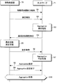
- FIG. 7 is a diagram illustrating an example of a sequence chart illustrating different frequency measurement that does not require gap control.
- FIG. 7 shows a procedure for shifting from a state where Carrier Aggregation is not performed to a state where Carrier Aggregation is performed.
- the mobile station apparatus 70 of this example has a reception bandwidth wider than at least 20 MHz and has the capability of carrying out Carrier Aggregation, but has not yet performed Carrier Aggregation (the state of Time 61 in FIG. 6). To do.
- the network 71 in the figure includes a base station device, a control station, and a host control station.
- the mobile station apparatus 70 transmits a mobile station apparatus capability report as an uplink message to the network 71 (step S1).
- the mobile station apparatus capability report includes at least receivable frequency band information, the possibility of carrier aggregation, and the maximum number of frequency bands that can be received simultaneously. It is desirable that the mobile station apparatus capability report is transmitted at least before the mobile station apparatus performs a measurement report in the communication state, and more preferably during the location registration procedure.
- the mobile station device 70 measures the in-zone cell and the neighboring cells of the same frequency, and transmits the measurement result to the network 71 by including it in the measurement report message (step S2).
- the network 71 performs aggregation pre-determination processing periodically or eventically (step S3), and when it is determined that Carrier Aggregation is necessary, transmits a different frequency measurement instruction message to the mobile station device 70 (step S4). .
- the mobile station device 70 performs different frequency measurement processing based on the control information instructed by the different frequency measurement instruction message (step S5), and transmits the measurement result by the different frequency measurement in the measurement report message (step S6).
- the network 71 receives the measurement report message, performs the aggregation determination process based on the measurement result (step S7), and transmits the frequency band newly received by the mobile station device 70 in the aggregation setting message when performing carrier aggregation. (Step S8).
- the mobile station device 70 starts reception processing of the designated frequency band and transmits an aggregation setting completion message to the network (step S9). As a result, the mobile station device 70 and the network 71 enter an aggregation state (step S10).
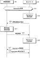
- FIG. 8 is a diagram illustrating another example of a sequence chart illustrating different frequency measurement that does not require gap control.
- FIG. 8 shows a procedure for changing the setting of Carrier Aggregation. It is assumed that the mobile station device 80 of this example has a reception bandwidth wider than at least 20 MHz and has a capability capable of carrier aggregation. Furthermore, the carrier aggregation state is set (step S11), but the reception bandwidth is not fully used (time 62 in FIG. 6).
- the network 81 in the figure includes a base station device, a control station, and a host control station.
- the network 81 performs aggregation pre-determination processing periodically or eventically (step S12), and when determining that additional carrier aggregation is necessary, transmits a different frequency measurement instruction message to the mobile station device (step S13). ).
- the mobile station device 80 performs different frequency measurement processing based on the control information instructed by the different frequency measurement instruction message (step S14), and transmits the measurement result by the different frequency measurement included in the measurement report message (step S15).
- the network 81 receives the measurement report message, performs the aggregation determination process based on the measurement result (step S16), and when resetting the carrier aggregation, information for changing the aggregation state of the mobile station apparatus is included in the aggregation reset message. It is transmitted including (step S17).
- the mobile station device 80 performs resetting in accordance with the designated information and transmits an aggregation resetting completion message to the network (step S18).
- FIG. 9 is a diagram illustrating an example of a sequence chart illustrating different frequency measurement that requires gap control.
- FIG. 9 shows gap control in the carrier aggregation state. It is assumed that the mobile station apparatus of this example has a reception bandwidth wider than at least 20 MHz, and has a capability capable of carrier aggregation. Further, the carrier aggregation state is set (step S19), and all reception bandwidths are used (time 63 in FIG. 6).
- the network in the figure includes a base station device, a control station, and a host control station.
- the network 91 performs aggregation pre-determination processing periodically or eventically (step S20), and when it is determined that the carrier aggregation needs to be reset, a measurement gap instruction message is transmitted to the mobile station apparatus (step S21). ).
- the mobile station device 90 reports the measurement gap completion to the network 91 (step S22), performs different frequency measurement processing based on the control information instructed by the measurement gap instruction message (step S23), and performs measurement by different frequency measurement. The result is included in the measurement report message and transmitted (step S24).
- the network 91 receives the measurement report message, performs an aggregation determination process based on the measurement result (step S25), and when resetting the carrier aggregation, information for changing the aggregation state of the mobile station apparatus is included in the aggregation reset message. It is transmitted including (step S26).
- the mobile station device 90 performs resetting according to the specified information and transmits an aggregation resetting completion message to the network (step S27).
- an existing control message may be reused by EUTRA.
- the different frequency measurement instruction message, the measurement gap instruction message, the aggregation setting message, and the aggregation reconfiguration message can be reused only by adding necessary parameters to the RRCConnectionReconfiguration message.
- the measurement gap completion message, the aggregation setting completion message, and the aggregation reconfiguration completion message can be reused only by adding the necessary parameters to the RRCConnectionReconfigurationComplete message.
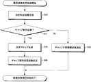
- FIG. 10 is a flowchart showing an example of the network aggregation pre-processing procedure in FIGS.
- This processing procedure is preferably performed by the base station apparatus, but the control station and the host control station may be provided with the processing procedure.
- the network acquires information regarding the state of the mobile station apparatus in communication. Subsequently, it is comprehensively determined from the acquired information whether the mobile station apparatus needs Carrier Aggregation (step S31). As the determination as to whether or not it is necessary, increase / decrease in the downlink data buffer amount, downlink throughput, the content of the measurement report reported from the mobile station apparatus, the number of users accommodated, and the like can be used.
- the downlink data buffer amount or the downlink throughput (which may be the average downlink throughput) exceeds a predetermined threshold, it is determined that aggregation is necessary. Further, if the reception quality of the reported frequency band in communication exceeds a predetermined threshold value or falls below, it is determined that aggregation is necessary.
- the reception quality of the downlink reference signal represented by EUTRA Carrier RSSI (Received Signal Strength Indicator), RSRP (Reference Signal Received Power), RSRQ (Reference Signal Received Quality), CQI (Channel Quality Indicator), path loss, etc. Use received measurements. Further, when the number of users accommodated exceeds or falls below a predetermined threshold, it is determined that aggregation is necessary. Furthermore, it is naturally possible to make a judgment by combining these plural conditions.
- Step S32 When Carrier Aggregation is necessary (Yes in Step S31), it is subsequently determined whether a measurement gap is necessary for different frequency measurement (Step S32).
- the mobile station apparatus is in the Carrear Aggregation and the mobile station apparatus uses all the receivers (reception units), it is determined that a measurement gap is necessary (Yes in step S32), and the measurement gap An instruction message is generated (step S33).
- different frequency measurement is possible without a measurement gap (No in step S32), that is, when the number of frequency bands received by the receiver of the mobile station apparatus is smaller than the number of receivers, different frequency measurement is performed.
- An instruction message is generated (step S34). And the produced
- parameters include gap information such as gap start timing, gap period and gap length, gap effective period, frequency information such as the center frequency and bandwidth of the frequency band to be measured, and cell information such as cell ID and individual cell offset. As necessary. These parameters are obtained from a combination of information from the broadcast information channel, fixed values in the system, and values specified in the measurement gap indication message.
- the frequency band for generating the measurement gap is, for example, a low-frequency band, a low-traffic frequency band, or a priority level.
- at least one is selected based on any criterion of the lower frequency band.
- the selection is performed by the mobile station device or the network.
- the network may select and indicate a plurality of frequency bands for the purpose of simultaneously measuring a plurality of different frequencies.
- frequency information such as the center frequency and bandwidth of the frequency band to be measured, and cell information such as cell ID and individual cell offset are required as parameters. These parameters are obtained from a combination of broadcast information channel information, a fixed value in the system, and information specified by a different frequency measurement instruction message.
- a priority indicating the order of measurement may be set. In this case, the priority may be specified in the broadcast information or may be specified individually in each downlink message. Note that if Carrier Aggregation is not required, the process ends.
- the flowchart shown in FIG. 10 is an example of a processing procedure in the base station apparatus in the network, for example, and the base station apparatus selects the necessity of Carrier Aggregation and the frequency band to be added for that purpose from the state of the mobile station apparatus. If a method of determining the necessity of a measurement gap when performing different frequency measurement for transmitting and transmitting a control message corresponding to the mobile station apparatus based on the determination, other processing procedures are used. Also good. As described above, this processing procedure can be provided in the control station and the upper control station.
- FIG. 11 is a flowchart showing an example of the different frequency measurement processing procedure of the mobile station apparatus in FIGS.
- the mobile station apparatus receives a downlink message regarding different frequency measurement transmitted from the network, and confirms the control content (step S36). Subsequently, it is determined whether a measurement gap is necessary according to the content of the downlink message (step S37). Specifically, when the downlink message is a different frequency measurement instruction message (No in step S37), a gap-unnecessary different frequency measurement is performed so as not to affect the frequency band being received (step S38).
- step S40 if the downlink message is a measurement gap instruction message (Yes in step S37), a measurement gap is generated based on the control parameter indicated by the control message (step S39), and the gap is used in the generated measurement gap section. Different frequency measurement is performed (step S40).
- the gap unnecessary different frequency measurement in step S38 is performed when the number of received frequency bands is smaller than the number of receivers (receivers). In this case, different frequency measurement is performed using an unused receiver, and the reception of the frequency band being received is continued. The gap-free different frequency measurement is performed based on parameters specified in the different frequency measurement instruction message.
- the gap use different frequency measurement in step S40 is performed when the number of received frequency bands is equal to the number of receivers. In this case, a measurement gap is generated in a frequency band received by at least one receiver, and different frequency measurement is performed in the measurement gap. The frequency band that does not generate the measurement gap is continuously received. The measurement gap is generated based on the parameters specified in the measurement gap instruction message in the measurement gap generation. And the gap unnecessary different frequency measurement is performed in the generated measurement gap section.
- the flowchart shown in FIG. 11 is an example of a processing procedure in the mobile station apparatus.
- the mobile station apparatus determines whether or not to generate a measurement gap at the time of different frequency measurement from the received measurement control information, and Any other processing procedure may be used as long as it is a method for performing different frequency measurement.
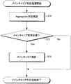
- FIG. 12 is a flowchart showing an example of the network aggregation determination processing procedure in FIGS.
- This processing procedure is preferably performed in the base station apparatus, but the control station and the host control station may be provided with the processing procedure.
- the base station apparatus acquires information regarding the state of the mobile station apparatus in communication.
- it is determined whether the target mobile station apparatus is currently set for Carrier Aggregation (during aggregation) (step S42). If aggregation is not in progress (No in step S42), it is comprehensively determined from the acquired information whether the mobile station apparatus needs Carrier Aggregation (step S43).
- the increase / decrease in the downlink data buffer amount, the downlink throughput, the content of the measurement report reported from the mobile station apparatus, the number of users accommodated, etc. can be used as the determination as to whether it is necessary.
- Step S43 When the base station apparatus does not require Carrere Aggregation (No in step S43), the base station apparatus ends the process without doing anything. On the other hand, if Carrier Aggregation is required in Step S43 (Yes in Step S43), a frequency band newly received for Aggregation is selected in Aggregation Frequency Setting (Step S44), and the selected frequency information is included.
- the aggregation setting message is generated (step S45). The frequency information is selected based on a frequency band having a quality equal to or higher than a predetermined threshold in a different frequency measurement report from the mobile station apparatus and a frequency band having a small amount of downlink traffic. Then, the aggregation setting message is transmitted to the mobile station apparatus (step S46), and the process is terminated.
- step S42 determines whether or not it is necessary to change the plurality of frequency bands selected for the carrier aggregation. If it is not necessary to reset the frequency band (No in step S47), the process ends without doing anything.
- step S47 when it is necessary to reset the frequency band (Yes in step S47), the frequency band to be changed for aggregation is selected by resetting the aggregation frequency (step S48), and the selected frequency information is included.
- the aggregation reconfiguration message is generated (step S49).
- the frequency band is selected based on, for example, a frequency band having a quality equal to or higher than a predetermined threshold in a different frequency measurement report from the mobile station apparatus and a frequency band having a small amount of downlink traffic.
- the frequency band to be reset can be specified to be added, deleted, or replaced at the same time. The addition is, for example, changing from receiving two frequency bands of A and B to receiving three frequency bands of A, B, and C.
- the frequency bands A and B that were originally received are continuously received.
- Deletion is, for example, changing from three frequency bands A, B, and C to receive two frequency bands A and C.
- the frequency bands of A and C that are not instructed to be deleted are continuously received as they are.
- the replacement is, for example, changing so that two frequency bands A and C are received from two frequency bands A and B.
- the frequency band A for which no replacement is instructed is received as it is.
- the aggregation reconfiguration message is transmitted to the mobile station apparatus (step S46), and the process is terminated.
- the flowchart in FIG. 12 is an example of a processing procedure in the base station apparatus in the network, for example, and the base station apparatus determines the necessity of Carrier Aggregation and the necessity of Carrier Aggregation reset from the state of the mobile station apparatus. Any other processing procedure may be used as long as it is a method for transmitting a control message corresponding to the mobile station apparatus based on the determination. As described above, this processing procedure can be provided in the control station and the upper control station.
- the mobile station apparatus determines whether or not a different frequency measurement is necessary (step S50).
- a different frequency measurement it is possible to use downlink throughput, reception quality of a frequency band during communication, and the like. For example, when the downlink throughput (which may be the average downlink throughput) exceeds a predetermined threshold, it is determined that the different frequency measurement is necessary. Further, when the reception quality of the frequency band being communicated exceeds or falls below a predetermined threshold, it is determined that a different frequency measurement is necessary.
- reception measurement values of downlink reference signals represented by EUTRA Carrier RSSI, RSRP, RSRQ, CQI, path loss, etc. are used as reception quality. Further, when aggregation is being performed, one or an average of a plurality of frequency bands may be used as reception quality.
- the threshold is specified by a broadcast information channel, a fixed value in the system, or an appropriate value set by the mobile station apparatus. If it is determined that the different frequency measurement is unnecessary (No in step S50), the process is terminated.
- step S50 when different frequency measurement is necessary (Yes in step S50), the mobile station apparatus transmits a downlink message related to different frequency measurement transmitted from the network in reception of measurement control information (in this example, only the measurement gap indication message). Is received (step S51).
- the measurement gap instruction message is received (Yes in step S51)
- a measurement gap is generated based on the control parameter instructed by the control message (step S52), and the gap use different frequency measurement is performed in the generated measurement gap section (step S52). Step S53).
- step S54 the mobile station apparatus determines whether gap-unnecessary different frequency measurement is possible.
- the gap-free different frequency measurement is performed when the number of received frequency bands is smaller than the number of receivers (receivers). If gap-free different frequency measurement is possible (Yes in step S54), the different frequency measurement is performed using an unused receiver (step S55), and the reception of the frequency band being received is continued as it is.
- the gap-free different frequency measurement is obtained from a combination of broadcast information channel information and a fixed value in the system.
- step S54 if it is not possible to measure a different frequency without a gap in step S54 (No in step S54), that is, if the number of received frequency bands is equal to the number of receivers, the process proceeds to step S51, and the network Continues to wait for reception of the measurement gap indication message.
- the flowchart in FIG. 13 is an example of a processing procedure in the mobile station apparatus.
- the mobile station apparatus determines whether the mobile station apparatus has received the aggregation state, the receiver usage state, and the measurement control information from the network. Based on this determination, it is determined whether to perform different frequency measurement that does not require a gap or different frequency measurement that requires a measurement gap. May be used.
- the mobile station apparatus performs different frequency measurement that does not require a measurement gap and different frequency measurement that requires a measurement gap.
- the network switches between different frequency measurement that does not require a measurement gap and different frequency measurement that requires a measurement gap, based on the state of the mobile station apparatus.
- the mobile station apparatus when the mobile station apparatus can perform the different frequency measurement without the measurement gap, it is not necessary to generate the measurement gap for the different frequency measurement, so that the downlink data throughput is improved.
- different frequency measurement can be performed regardless of the measurement gap length, the measurement accuracy of the different frequency measurement is improved.
- unnecessary measurement reporting is not required, and power consumption is reduced.
- a mobile station device when a mobile station device can perform different frequency measurement without a measurement gap, a device in the network (base station device, control station, host control station) does not need to generate a measurement gap, and therefore scheduling is simplified. .
- the control gap during aggregation is freely specified by a network instruction.
- the complexity of the mobile station apparatus and the network is reduced by limiting the frequency band in which the measurement gap is set based on a predetermined condition rather than setting the measurement gap in an arbitrary frequency band.
- a method for reducing complexity by classifying frequency bands into main carriers and non-main carriers will be described.
- the receiver and transmitter of the mobile station apparatus and the receiver and transmitter of the base station apparatus in this embodiment may be the same as those in the first embodiment.
- the main carrier and non-main carrier shown in this embodiment will be described below.
- the main carrier is a frequency band in which a control message is transmitted during the implementation of Carrier Aggregation.
- the non-main carrier is a frequency band in which only traffic data for which no control message is transmitted is transmitted.
- the main carrier is equal to the frequency band being received.
- the main carrier is selected by the network using an arbitrary method and is designated as the mobile station device, or the mobile station device determines based on a predetermined determination. For example, when the network selects, the content of the measurement report reported from the mobile station device, the number of users accommodated, the transmission bandwidth, the transmission frequency, etc. can be used.
- the frequency band received before carrying out Carrier Aggregation can be used as the main carrier.
- FIG. 14 is a diagram showing an example of a sequence chart showing the procedure for changing the main carrier.
- FIG. 14 shows a procedure for changing the main carrier in a state where the mobile station apparatus 140 is performing Carrier Aggregation.
- the mobile station device 140 has the capability of receiving three frequency bands at the same time.
- the mobile station device 140 has the Band1 base station device 141, the Band2 base station device 142, and the Band3 base station device 143. It starts from the state where the three base station apparatuses are performing Carrier Aggregation.
- One base station apparatus may transmit a plurality of frequency bands. An example in which the main carrier is changed from the frequency band transmitted from the Band1 base station apparatus 141 to the frequency band transmitted from the Band2 base station apparatus 142 is shown.
- the main carrier at the start time is assumed to be a frequency band transmitted from the Band1 base station apparatus 141. That is, the control message (layer 3 message) is transmitted and received between the mobile station device 140 and the Band1 base station device 141, and is controlled between the Band2 base station device 142, the Band3 base station device 143, and the mobile station device. Messages are not being sent or received.
- the mobile station device 140 When the mobile station device 140 is in a communication state, the mobile station device 140 measures the base station device being aggregated (step S60) and its surrounding cells, and transmits the measurement result to the Band1 base station device 141 in a measurement report message. (Step S61).
- the Band1 base station apparatus 141 performs main carrier determination processing periodically or in an event (step S62), and when it is determined that the main carrier needs to be changed, the main carrier base after changing the main carrier change preparation message It transmits to the station apparatus 142 by the message between base stations (step S63).
- the base station apparatus 142 of the main carrier after the change returns a main carrier change preparation completion message as an inter-base station message as a response (step S64).
- a main carrier change preparation message is transmitted from the Band1 base station apparatus 141 to the Band2 base station apparatus 142
- a main carrier change preparation completion message is transmitted from the Band2 base station apparatus 142 to the Band1 base station apparatus 141.
- the Band1 base station device 141 transmits a main carrier change instruction message to the mobile station device (step S65).
- the mobile station device 140 changes the main carrier based on the control information instructed by the main carrier change instruction message, and transmits a main carrier change completion message to the Band2 base station device 142 (step S66).
- the mobile station device 140 starts transmission / reception of a control message with the Band2 base station device 142 (step S67).
- the main carrier change instruction message includes information such as the center frequency of the frequency band or the cell ID of the base station device. Alternatively, when it is necessary to change the uplink frequency band at the same time, preamble information regarding the random access channel may be designated.
- the main carrier change preparation message includes a cell ID or a global ID, and information on the mobile station apparatus held by the main carrier.
- an existing control message may be reused in EUTRA.
- the main carrier change instruction message can be reused only by adding necessary parameters to the RRCConnectionReconfiguration message.
- the main carrier change completion message can be reused only by adding necessary parameters to the RRCConnectionReconfigurationComplete message. Note that the procedure for changing the main carrier when the aggregation is not in progress may be the same as the normal handover procedure.
- FIG. 15 is a flowchart showing an example of the main carrier determination processing procedure shown in step S62 in FIG.
- This processing procedure is preferably performed in the base station apparatus set as the main carrier, but the control station and the upper control station may be provided with the processing procedure.
- the base station apparatus set as the main carrier acquires information related to aggregation in the aggregation state confirmation (step S70). Subsequently, it is comprehensively determined from the acquired information whether the main carrier needs to be changed (step S71).
- the content of the measurement report reported from the mobile station device, the number of users accommodated, the transmission bandwidth, the transmission frequency, and the like can be used. For example, if the reception quality of the frequency band of the base station device of the main carrier falls below a predetermined threshold, it is determined that the main carrier needs to be changed to the frequency band of the best reception quality.
- reception measurement values of downlink reference signals represented by EUTRA Carrier RSSI, RSRP, RSRQ, CQI, path loss, etc. are used as reception quality. Further, when the number of users accommodated in the base station device of the main carrier exceeds a predetermined threshold, it is determined that the main carrier needs to be changed to the frequency band having the smallest number of users accommodated. Further, when a new frequency band having a wider transmission bandwidth than the main carrier is newly received by Carrier Aggregation, it is determined that the main carrier needs to be changed to the frequency band having the maximum transmission bandwidth. Further, when a transmission frequency having better propagation characteristics than the main carrier is newly received by Carrier Aggregation, it is determined that the main carrier needs to be changed to the frequency band of the best transmission frequency.
- the propagation characteristic is, for example, frequency straightness. Furthermore, it is naturally possible to make a judgment by combining these plural conditions.
- step S71 If it is not necessary to change the main carrier in step S71 (No in step S71), the process is terminated without doing anything. On the other hand, if the main carrier needs to be changed in step S71 (Yes in step S71), a more optimal frequency band is selected as the main carrier (step S72), and the process is completed.
- the method for selecting the main carrier may be any method described above.
- the flowchart shown in FIG. 15 is an example of a processing procedure in the base station apparatus set as the main carrier, for example, and the base station apparatus needs to change the main carrier from the state of the mobile station apparatus and the state of the network. As long as it is a method that can select an optimal main carrier based on the above determination, a processing procedure other than this may be used. As described above, this processing procedure can be provided in the control station and the upper control station.
- FIG. 16 is a diagram illustrating an example in which a measurement gap is generated with a non-main carrier when a measurement gap is indicated. Since there is no need to generate a measurement gap in the main carrier, there is an advantage that a delay of the control message does not occur.
- the gap information such as the gap start timing, the gap period and the gap length, and the effective period of the gap
- information indicating which frequency band to generate the measurement gap ( The center frequency of the frequency band, the frequency ID (also referred to as EARFCN), or the cell ID of the base station device, and combinations thereof are included.
- FIG. 17 is a diagram illustrating an example in which a measurement gap is generated by a main carrier when a measurement gap is indicated. Unlike FIG. 16, since the measurement gap is generated only on the main carrier, information indicating which frequency band to generate the measurement gap is unnecessary. Further, since the measurement gap generation method is the same regardless of the presence or absence of Carrier Aggregation, there is an advantage that the processing procedure is simplified. Also, EUTRA and gap generation processing can be shared.
- the mobile station apparatus and the network classify the frequency band in the carrier aggregation into a main carrier and a non-main carrier. Then, either one of them generates a measurement gap and performs different frequency measurement.
- the mobile station device and the devices in the network can simplify the processing procedure related to the measurement gap. Configuration is simplified.
- the function of each unit of the mobile station apparatus and the base station apparatus or a program for realizing a part of these functions is recorded on a computer-readable recording medium and recorded on this recording medium.
- the mobile station apparatus or the base station apparatus may be controlled by causing the computer system to read and execute the program.
- the “computer system” includes an OS and hardware such as peripheral devices.
- the “computer-readable recording medium” refers to a storage device such as a flexible medium, a magneto-optical disk, a portable medium such as a ROM or a CD-ROM, and a hard disk incorporated in a computer system.
- the “computer-readable recording medium” dynamically holds a program for a short time, like a communication line when transmitting a program via a network such as the Internet or a communication line such as a telephone line.
- a server that holds a program for a certain time such as a volatile memory inside a computer system that serves as a server or client.
- the program may be a program for realizing a part of the functions described above, and may be a program capable of realizing the functions described above in combination with a program already recorded in a computer system.
Landscapes
- Engineering & Computer Science (AREA)
- Computer Networks & Wireless Communication (AREA)
- Signal Processing (AREA)
- Mobile Radio Communication Systems (AREA)
- Monitoring And Testing Of Transmission In General (AREA)
Abstract
Priority Applications (6)
| Application Number | Priority Date | Filing Date | Title |
|---|---|---|---|
| JP2010529731A JP4961040B2 (ja) | 2008-09-22 | 2009-09-10 | 基地局装置、移動局装置、移動通信システムおよび通信方法 |
| US13/120,119 US8639239B2 (en) | 2008-09-22 | 2009-09-10 | Base station apparatus, mobile station apparatus, mobile communication system and communication method having selectable inter-frequency measurement methods |
| CN200980137213.6A CN102160414B (zh) | 2008-09-22 | 2009-09-10 | 基站装置、移动站装置、移动通信系统以及通信方法 |
| EP09814520.4A EP2341730B1 (fr) | 2008-09-22 | 2009-09-10 | Mesures par un terminal utilisant l'aggrégation de porteuses |
| ZA2011/02508A ZA201102508B (en) | 2008-09-22 | 2011-04-05 | Base station apparatus, mobile station apparatus, mobile communication system and communication method |
| US14/105,400 US9084148B2 (en) | 2008-09-22 | 2013-12-13 | Communications based on measurements using and not using a measurement gap |
Applications Claiming Priority (2)
| Application Number | Priority Date | Filing Date | Title |
|---|---|---|---|
| JP2008243263 | 2008-09-22 | ||
| JP2008-243263 | 2008-09-22 |
Related Child Applications (2)
| Application Number | Title | Priority Date | Filing Date |
|---|---|---|---|
| US13/120,119 A-371-Of-International US8639239B2 (en) | 2008-09-22 | 2009-09-10 | Base station apparatus, mobile station apparatus, mobile communication system and communication method having selectable inter-frequency measurement methods |
| US14/105,400 Division US9084148B2 (en) | 2008-09-22 | 2013-12-13 | Communications based on measurements using and not using a measurement gap |
Publications (1)
| Publication Number | Publication Date |
|---|---|
| WO2010032675A1 true WO2010032675A1 (fr) | 2010-03-25 |
Family
ID=42039499
Family Applications (1)
| Application Number | Title | Priority Date | Filing Date |
|---|---|---|---|
| PCT/JP2009/065834 WO2010032675A1 (fr) | 2008-09-22 | 2009-09-10 | Dispositif de station de base, dispositif de station mobile, systeme de communication mobile et procede de communication |
Country Status (6)
| Country | Link |
|---|---|
| US (2) | US8639239B2 (fr) |
| EP (1) | EP2341730B1 (fr) |
| JP (2) | JP4961040B2 (fr) |
| CN (1) | CN102160414B (fr) |
| WO (1) | WO2010032675A1 (fr) |
| ZA (1) | ZA201102508B (fr) |
Cited By (30)
| Publication number | Priority date | Publication date | Assignee | Title |
|---|---|---|---|---|
| JP2010273343A (ja) * | 2009-05-21 | 2010-12-02 | Innovative Sonic Corp | 測定ギャップ設定装置および方法 |
| WO2011148770A1 (fr) * | 2010-05-24 | 2011-12-01 | 株式会社 エヌ・ティ・ティ・ドコモ | Station mobile, station de base sans fil, et procédé de commande de communication |
| JP2012199916A (ja) * | 2011-03-14 | 2012-10-18 | Mitsubishi Electric R&D Centre Europe B.V. | データを転送及び/又は受信することを可能にする方法及び装置、いずれの周波数帯域を用いなくてはならないかを求める方法、並びに集中化デバイス |
| JP2013507068A (ja) * | 2009-10-01 | 2013-02-28 | インターデイジタル パテント ホールディングス インコーポレイテッド | マルチ受信機無線送受信ユニット(wtru)において周波数間測定および/または無線アクセス技術(rat)間測定を実行する方法および装置 |
| EP2568757A1 (fr) * | 2010-06-03 | 2013-03-13 | Huawei Technologies Co., Ltd. | Procédé de mesure pour la gestion de cellules, station de base et système de communications |
| WO2012022370A3 (fr) * | 2010-08-16 | 2013-03-28 | Nokia Siemens Networks Oy | Planification de porteuses de composantes |
| JP2013524700A (ja) * | 2010-08-16 | 2013-06-17 | ゼットティーイー コーポレーション | チャネル状態情報の報告方法及び基地局 |
| JP5272074B2 (ja) * | 2009-04-28 | 2013-08-28 | 株式会社エヌ・ティ・ティ・ドコモ | 移動通信システム、無線基地局及び制御方法 |
| JP2013534799A (ja) * | 2010-08-13 | 2013-09-05 | 電信科学技術研究院 | 一種の搬送波重合能力の処理方法と設備 |
| JP2013536644A (ja) * | 2010-08-20 | 2013-09-19 | ゼットティーイー コーポレーション | 圧縮モードの制御方法及びシステム |
| JP2014504055A (ja) * | 2010-11-08 | 2014-02-13 | クゥアルコム・インコーポレイテッド | マルチキャリアシステムにおける周波数間測定制御 |
| JP2014039282A (ja) * | 2009-06-19 | 2014-02-27 | Qualcomm Incorporated | マルチキャリア動作において測定プロシージャを容易にする方法および装置 |
| JP2014049956A (ja) * | 2012-08-31 | 2014-03-17 | Ntt Docomo Inc | 移動局 |
| EP2725861A1 (fr) * | 2011-06-21 | 2014-04-30 | Sharp Kabushiki Kaisha | Dispositif de station mobile, dispositif de station de base, système de communication, procédé de notification de capacité de dispositif de station mobile et circuit intégré |
| JP5555246B2 (ja) * | 2009-10-06 | 2014-07-23 | 株式会社Nttドコモ | 基地局装置及びユーザ装置 |
| JP2014150558A (ja) * | 2010-04-30 | 2014-08-21 | Sony Corp | コンポーネントキャリアを更新する電子装置、方法、及びコンピュータ記憶媒体 |
| JP2014525698A (ja) * | 2011-08-12 | 2014-09-29 | テレフオンアクチーボラゲット エル エム エリクソン(パブル) | ユーザ装置、ネットワークノード、その中の第2のネットワークノード、および方法 |
| JP2015508961A (ja) * | 2012-01-30 | 2015-03-23 | クアルコム,インコーポレイテッド | ワイヤレスネットワークのための柔軟な無線リソース管理(rrm)測定 |
| JP2015514358A (ja) * | 2012-03-19 | 2015-05-18 | クゥアルコム・インコーポレイテッドQualcomm Incorporated | Gsmチャネルを同時に監視する方法および装置 |
| WO2015107783A1 (fr) * | 2014-01-14 | 2015-07-23 | ソニー株式会社 | Appareil de communication, procédé de transmission de données de commande de communication et procédé de réception de données de commande de communication |
| JP2015164317A (ja) * | 2010-02-12 | 2015-09-10 | インターデイジタル テクノロジー コーポレーション | 複数のサイト間のデータ分割 |
| JP2016012859A (ja) * | 2014-06-30 | 2016-01-21 | 株式会社Nttドコモ | 基地局および移動通信制御方法 |
| WO2017051902A1 (fr) * | 2015-09-24 | 2017-03-30 | 株式会社Nttドコモ | Terminal d'utilisateur, station de base sans fil, et procédé de communication sans fil |
| JPWO2015170579A1 (ja) * | 2014-05-09 | 2017-04-20 | 株式会社Nttドコモ | ユーザ装置、基地局及び方法 |
| CN106851721A (zh) * | 2011-01-10 | 2017-06-13 | 联发科技股份有限公司 | 测量间隙报告配置方法和用户设备 |
| US9699779B2 (en) | 2012-08-23 | 2017-07-04 | Interdigital Patent Holdings, Inc. | Physical layer operation for multi-layer operation in a wireless system |
| US9763282B2 (en) | 2012-08-23 | 2017-09-12 | Interdigital Patent Holdings, Inc. | Operating with multiple schedulers in a wireless system |
| JP2017530602A (ja) * | 2014-09-26 | 2017-10-12 | インテル アイピー コーポレーション | 増加した搬送波の監視 |
| US10560944B2 (en) | 2010-12-03 | 2020-02-11 | Interdigital Patent Holdings, Inc. | Methods, apparatus and systems for performing multi-radio access technology carrier aggregation |
| US11838849B2 (en) | 2011-07-29 | 2023-12-05 | Interdigital Patent Holdings, Inc. | Methods and apparatus for radio resources management in multi-radio access technology wireless systems |
Families Citing this family (41)
| Publication number | Priority date | Publication date | Assignee | Title |
|---|---|---|---|---|
| US9036607B2 (en) * | 2006-05-23 | 2015-05-19 | Sharp Kabushiki Kaisha | Method, mobile station device, base station device, and mobile communication system for gap-generation determination |
| EP2341730B1 (fr) * | 2008-09-22 | 2017-11-29 | Sharp Kabushiki Kaisha | Mesures par un terminal utilisant l'aggrégation de porteuses |
| CN101932045B (zh) * | 2009-06-24 | 2014-11-05 | 中兴通讯股份有限公司 | 载波聚合中测量结果的上报方法及用户设备 |
| US20110128919A1 (en) * | 2009-11-30 | 2011-06-02 | Samsung Electronics Co. Ltd. | Device and method for selecting transceiver in mobile communication system |
| WO2012112101A1 (fr) * | 2011-02-15 | 2012-08-23 | Telefonaktiebolaget L M Ericsson (Publ) | Configuration de largeur de bande de transmission de signal de référence |
| US9025478B2 (en) * | 2011-08-16 | 2015-05-05 | Google Technology Holdings LLC | Self-interference handling in a wireless communication terminal supporting carrier aggregation |
| JP5806139B2 (ja) * | 2012-01-30 | 2015-11-10 | 株式会社Nttドコモ | 移動通信システム |
| CN104145498A (zh) * | 2012-03-01 | 2014-11-12 | 日本电气株式会社 | 移动终端装置、无线通信系统、移动终端装置通信方法和程序 |
| JP5822765B2 (ja) * | 2012-03-19 | 2015-11-24 | シャープ株式会社 | 無線通信システム、通信方法、端末装置、および基地局装置 |
| JP5962266B2 (ja) * | 2012-07-05 | 2016-08-03 | 富士通株式会社 | 受信品質測定方法及び移動端末装置 |
| US9337966B2 (en) * | 2012-07-25 | 2016-05-10 | Nec Corporation | Carrier aggregation |
| WO2014161178A1 (fr) * | 2013-04-03 | 2014-10-09 | 华为技术有限公司 | Procédé et dispositif pour mesurer une cellule inter-fréquence |
| EP2993937B1 (fr) * | 2013-05-31 | 2017-09-27 | Huawei Technologies Co., Ltd. | Procédé de communication, station de base, et équipement d'utilisateur |
| KR102133287B1 (ko) * | 2013-07-26 | 2020-07-13 | 삼성전자 주식회사 | 이동통신 시스템에서 효과적인 다중 반송파 다중 셀 스케줄링 장치 및 방법 |
| US9137695B2 (en) * | 2013-08-05 | 2015-09-15 | Qualcomm Incorporated | Apparatus and methods for continuous inter-frequency measurement reconfigurations of DC-HSUPA UE |
| KR102107022B1 (ko) * | 2013-09-16 | 2020-05-07 | 주식회사 팬택 | 반송파 집성 동작을 제어하는 단말기 및 방법 |
| US9414384B2 (en) | 2013-09-17 | 2016-08-09 | Telefonaktiebolaget Lm Ericsson (Publ) | State-driven secondary cell activation and deactivation |
| KR102104547B1 (ko) * | 2013-09-26 | 2020-04-24 | 에스케이텔레콤 주식회사 | 기지국장치 및 기지국장치의 동작 방법 |
| JP2015095881A (ja) * | 2013-11-14 | 2015-05-18 | 株式会社Nttドコモ | 移動局 |
| EP3090510A4 (fr) | 2013-12-31 | 2017-11-29 | Bandwidthx Inc. | Systèmes et procédés d'attribution de ressources à des réseaux d'accès alternatifs |
| US9973958B2 (en) * | 2014-01-30 | 2018-05-15 | Intel IP Corporation | Systems, methods, and devices for improved inter-frequency measurement |
| US9729175B2 (en) * | 2014-05-08 | 2017-08-08 | Intel IP Corporation | Techniques to manage radio frequency chains |
| US9699784B2 (en) * | 2014-06-13 | 2017-07-04 | Apple Inc. | Systems and methods for establishing wireless communications between wireless circuitry and multiple base stations |
| US10075888B2 (en) | 2014-09-25 | 2018-09-11 | Qualcomm Incorporated | Service-specific air-interface selection |
| US9755767B2 (en) * | 2014-10-31 | 2017-09-05 | Qualcomm Incorporated | Mechanism to measure, report, and allocate a highest possible rank for each cell in a carrier aggregation (CA) mode receiver-limited user equipment (UE) |
| CN107431989B (zh) * | 2015-04-03 | 2021-02-09 | 株式会社Ntt都科摩 | 用户装置以及基站 |
| EP4250600A3 (fr) * | 2015-04-10 | 2023-11-29 | Mitsubishi Electric Corporation | Appareil utilisateur, station de base et système de communication |
| CN107409320B (zh) * | 2015-05-15 | 2021-02-12 | 华为技术有限公司 | 载波聚合能力上报、载波测量装置及方法 |
| EP3335342B1 (fr) * | 2015-08-14 | 2020-04-01 | Sony Corporation | Dispositifs et procédés permettant d'arrêter des mesures de cqi selon le niveau de batterie ou la mobilité d'équipement utilisateur (ue) dans un système multiporteuse |
| WO2017059064A1 (fr) * | 2015-09-29 | 2017-04-06 | Bandwidthx Inc. | Authentification et autorisation de dispositifs mobiles pour utilisation de points d'accès dans un réseau de substitution |
| US10368393B2 (en) * | 2016-06-10 | 2019-07-30 | Nokia Technologies Oy | Methods and apparatuses for enhancing the setup of carrier aggregation, dual connectivity, multi connectivity, license assisted access, or LTE-WLAN in communications networks |
| EP3508003A1 (fr) | 2016-09-01 | 2019-07-10 | Telefonaktiebolaget LM Ericsson (PUBL) | Transfert intercellulaire intra-bandes de la même fréquence physique |
| US11019544B2 (en) * | 2017-02-02 | 2021-05-25 | Samsung Electronics Co., Ltd. | Method and apparatus for transmitting and receiving data in mobile communication system |
| CN109788497A (zh) * | 2017-11-10 | 2019-05-21 | 维沃移动通信有限公司 | 测量间隔的指示方法、接收方法、终端及网络设备 |
| US11202262B2 (en) * | 2017-12-30 | 2021-12-14 | Dugan Patents, Llc | Methods and apparatus for reducing mobile telephone power consumption and/or radiation exposure |
| EP3738343A1 (fr) | 2018-01-11 | 2020-11-18 | Telefonaktiebolaget LM Ericsson (publ) | Première station de base, seconde station de base, équipement utilisateur et procédés effectués par ceux-ci, permettant de gérer un changement d'une ou de plusieurs mesures |
| JP6509410B2 (ja) * | 2018-06-15 | 2019-05-08 | 株式会社Nttドコモ | 移動端末、基地局及び通信制御方法 |
| KR20220065030A (ko) * | 2019-09-24 | 2022-05-19 | 오로페 프랑스 에스에이알엘 | 다운 링크 피드백 지시 처리를 위한 방법 및 기기 |
| CN113079526B (zh) * | 2020-01-06 | 2024-02-23 | 联发科技股份有限公司 | 报告新无线电测量间隙请求信息的用户设备及其方法 |
| US11611954B2 (en) | 2020-04-17 | 2023-03-21 | Samsung Electronics Co., Ltd | System and method for physical downlink control channel monitoring based on user equipment capability |
| US20220150904A1 (en) * | 2020-11-06 | 2022-05-12 | Qualcomm Incorporated | Techniques for enhanced handling of network measurements |
Citations (4)
| Publication number | Priority date | Publication date | Assignee | Title |
|---|---|---|---|---|
| WO2006046307A1 (fr) | 2004-10-29 | 2006-05-04 | Fujitsu Limited | Dispositif de communication par la méthode de transmission par multiporteuse et système de communication |
| JP2006222845A (ja) * | 2005-02-14 | 2006-08-24 | Nec Corp | 基地局制御装置、移動体通信システム、および近隣セルリストフィルタリング方法 |
| WO2008102531A1 (fr) * | 2007-02-23 | 2008-08-28 | Panasonic Corporation | Dispositif de terminal de communication radio et procédé de mesure de cellule adjacente |
| JP2008205566A (ja) * | 2007-02-16 | 2008-09-04 | Sharp Corp | 移動通信システム、基地局装置、移動局装置及び移動通信方法 |
Family Cites Families (21)
| Publication number | Priority date | Publication date | Assignee | Title |
|---|---|---|---|---|
| FI112562B (fi) | 2000-02-29 | 2003-12-15 | Nokia Corp | Mittausaukkojen määrittäminen keskinäistaajuksien mittauksessa |
| JP4227737B2 (ja) * | 2000-08-30 | 2009-02-18 | 日本電気株式会社 | 無線ネットワーク、中継ノード及びそれに用いる中継伝送方法並びにそのプログラム |
| JP2003078957A (ja) | 2001-08-31 | 2003-03-14 | Nec Corp | 複合情報端末、移動通信システム、その制御方法 |
| FR2838019B1 (fr) | 2002-03-29 | 2004-08-27 | Evolium Sas | Procede de configuration de mode compresse dans un systeme de radiocommunications mobiles |
| ES2302876T3 (es) | 2003-04-11 | 2008-08-01 | Telefonaktiebolaget Lm Ericsson (Publ) | Metodo de sincronizacion en un terminal de radio movil. |
| JP3938914B2 (ja) | 2003-08-08 | 2007-06-27 | 松下電器産業株式会社 | 移動局装置および移動局装置における回線品質報告値制御方法 |
| JP2005064751A (ja) | 2003-08-08 | 2005-03-10 | Matsushita Electric Ind Co Ltd | 移動局装置および移動局装置における受信方法 |
| JP2005064571A (ja) | 2003-08-12 | 2005-03-10 | Hitachi Ltd | 情報伝達システム及び情報伝達装置 |
| JP4175510B2 (ja) | 2003-08-29 | 2008-11-05 | ソニー・エリクソン・モバイルコミュニケーションズ株式会社 | 移動体端末、無線中継装置、移動通信システム |
| JP2005354196A (ja) | 2004-06-08 | 2005-12-22 | Matsushita Electric Ind Co Ltd | 無線通信装置及び無線通信方法 |
| AU2005203370A1 (en) | 2004-08-10 | 2006-03-02 | Nec Australia Pty Ltd | Method and apparatus for a UMTS network operating in compressed mode |
| CN1738442A (zh) | 2004-08-10 | 2006-02-22 | 日本电气株式会社 | 用于工作在压缩模式下的无线通信网络的方法和装置 |
| JP5049463B2 (ja) | 2004-12-14 | 2012-10-17 | 富士通株式会社 | 無線通信システム及び基地局及び移動局及び無線通信方法 |
| US8358629B2 (en) | 2005-11-01 | 2013-01-22 | Qualcomm Incorporated | Mobile device-initiated measurement gap request |
| JP4762680B2 (ja) | 2005-11-04 | 2011-08-31 | 株式会社エヌ・ティ・ティ・ドコモ | キャリア方法通知方法、周辺セル測定方法、基地局装置および移動局装置 |
| KR101358469B1 (ko) * | 2006-02-07 | 2014-02-06 | 엘지전자 주식회사 | 무선 네트워크(network) 안에서 상향(uplink)및 하향(downlink) 대역폭(bandwidth)의선택 및 신호 방법 |
| US9036607B2 (en) | 2006-05-23 | 2015-05-19 | Sharp Kabushiki Kaisha | Method, mobile station device, base station device, and mobile communication system for gap-generation determination |
| US7706329B2 (en) * | 2006-10-24 | 2010-04-27 | Telefonaktiebolaget L M Ericsson (Publ) | Method and apparatus for compressed mode handling in a dual receiver user equipment (UE) |
| KR20090122272A (ko) * | 2007-01-08 | 2009-11-26 | 인터디지탈 테크날러지 코포레이션 | 이동성을 지원하는 측정 갭 패턴 스케쥴링 |
| JPWO2010007763A1 (ja) | 2008-07-15 | 2012-01-05 | パナソニック株式会社 | 無線受信装置、及び、使用単位バンド外参照信号のメジャメント方法 |
| EP2341730B1 (fr) * | 2008-09-22 | 2017-11-29 | Sharp Kabushiki Kaisha | Mesures par un terminal utilisant l'aggrégation de porteuses |
-
2009
- 2009-09-10 EP EP09814520.4A patent/EP2341730B1/fr active Active
- 2009-09-10 WO PCT/JP2009/065834 patent/WO2010032675A1/fr active Application Filing
- 2009-09-10 US US13/120,119 patent/US8639239B2/en not_active Expired - Fee Related
- 2009-09-10 CN CN200980137213.6A patent/CN102160414B/zh active Active
- 2009-09-10 JP JP2010529731A patent/JP4961040B2/ja active Active
-
2011
- 2011-04-05 ZA ZA2011/02508A patent/ZA201102508B/en unknown
-
2012
- 2012-03-23 JP JP2012067736A patent/JP5436601B2/ja not_active Expired - Fee Related
-
2013
- 2013-12-13 US US14/105,400 patent/US9084148B2/en active Active
Patent Citations (4)
| Publication number | Priority date | Publication date | Assignee | Title |
|---|---|---|---|---|
| WO2006046307A1 (fr) | 2004-10-29 | 2006-05-04 | Fujitsu Limited | Dispositif de communication par la méthode de transmission par multiporteuse et système de communication |
| JP2006222845A (ja) * | 2005-02-14 | 2006-08-24 | Nec Corp | 基地局制御装置、移動体通信システム、および近隣セルリストフィルタリング方法 |
| JP2008205566A (ja) * | 2007-02-16 | 2008-09-04 | Sharp Corp | 移動通信システム、基地局装置、移動局装置及び移動通信方法 |
| WO2008102531A1 (fr) * | 2007-02-23 | 2008-08-28 | Panasonic Corporation | Dispositif de terminal de communication radio et procédé de mesure de cellule adjacente |
Non-Patent Citations (1)
| Title |
|---|
| See also references of EP2341730A4 |
Cited By (59)
| Publication number | Priority date | Publication date | Assignee | Title |
|---|---|---|---|---|
| JP5272074B2 (ja) * | 2009-04-28 | 2013-08-28 | 株式会社エヌ・ティ・ティ・ドコモ | 移動通信システム、無線基地局及び制御方法 |
| JP2010273343A (ja) * | 2009-05-21 | 2010-12-02 | Innovative Sonic Corp | 測定ギャップ設定装置および方法 |
| JP2014039282A (ja) * | 2009-06-19 | 2014-02-27 | Qualcomm Incorporated | マルチキャリア動作において測定プロシージャを容易にする方法および装置 |
| US9332464B2 (en) | 2009-06-19 | 2016-05-03 | Qualcomm Incorporated | Method and apparatus that facilitates measurement procedures in multicarrier operation |
| JP2013507068A (ja) * | 2009-10-01 | 2013-02-28 | インターデイジタル パテント ホールディングス インコーポレイテッド | マルチ受信機無線送受信ユニット(wtru)において周波数間測定および/または無線アクセス技術(rat)間測定を実行する方法および装置 |
| JP2016034148A (ja) * | 2009-10-01 | 2016-03-10 | インターデイジタル パテント ホールディングス インコーポレイテッド | マルチ受信機無線送受信ユニット(wtru)において周波数間測定および/または無線アクセス技術(rat)間測定を実行する方法および装置 |
| JP2014207691A (ja) * | 2009-10-01 | 2014-10-30 | インターデイジタル パテント ホールディングス インコーポレイテッド | マルチ受信機無線送受信ユニット(wtru)において周波数間測定および/または無線アクセス技術(rat)間測定を実行する方法および装置 |
| JP5555246B2 (ja) * | 2009-10-06 | 2014-07-23 | 株式会社Nttドコモ | 基地局装置及びユーザ装置 |
| US9973322B2 (en) | 2010-02-12 | 2018-05-15 | Interdigital Technology Corporation | Data split between multiple sites |
| JP2015164317A (ja) * | 2010-02-12 | 2015-09-10 | インターデイジタル テクノロジー コーポレーション | 複数のサイト間のデータ分割 |
| US10212707B2 (en) | 2010-04-30 | 2019-02-19 | Sony Corporation | Method, base station, terminal and communication system for updating component carrier |
| JP2014150558A (ja) * | 2010-04-30 | 2014-08-21 | Sony Corp | コンポーネントキャリアを更新する電子装置、方法、及びコンピュータ記憶媒体 |
| US9750023B2 (en) | 2010-04-30 | 2017-08-29 | Sony Corporation | Method, base station, terminal and communication system for updating component carrier |
| US10912092B2 (en) | 2010-04-30 | 2021-02-02 | Sony Corporation | Method, base station, terminal and communication system for updating component carrier |
| CN103026772A (zh) * | 2010-05-24 | 2013-04-03 | 株式会社Ntt都科摩 | 移动台、无线基站以及通信控制方法 |
| JP5421457B2 (ja) * | 2010-05-24 | 2014-02-19 | 株式会社Nttドコモ | 移動局、無線基地局及び通信制御方法 |
| WO2011148770A1 (fr) * | 2010-05-24 | 2011-12-01 | 株式会社 エヌ・ティ・ティ・ドコモ | Station mobile, station de base sans fil, et procédé de commande de communication |
| EP2568757A1 (fr) * | 2010-06-03 | 2013-03-13 | Huawei Technologies Co., Ltd. | Procédé de mesure pour la gestion de cellules, station de base et système de communications |
| US9615245B2 (en) | 2010-08-13 | 2017-04-04 | China Academy Of Telecommunications Technology | Method and device for processing carrier aggregation capability |
| JP2013534799A (ja) * | 2010-08-13 | 2013-09-05 | 電信科学技術研究院 | 一種の搬送波重合能力の処理方法と設備 |
| JP2013524700A (ja) * | 2010-08-16 | 2013-06-17 | ゼットティーイー コーポレーション | チャネル状態情報の報告方法及び基地局 |
| WO2012022370A3 (fr) * | 2010-08-16 | 2013-03-28 | Nokia Siemens Networks Oy | Planification de porteuses de composantes |
| US9014123B2 (en) | 2010-08-20 | 2015-04-21 | Zte Corporation | Method for controlling compressed mode and system thereof |
| JP2013536644A (ja) * | 2010-08-20 | 2013-09-19 | ゼットティーイー コーポレーション | 圧縮モードの制御方法及びシステム |
| JP2014504055A (ja) * | 2010-11-08 | 2014-02-13 | クゥアルコム・インコーポレイテッド | マルチキャリアシステムにおける周波数間測定制御 |
| US9467885B2 (en) | 2010-11-08 | 2016-10-11 | Qualcomm Incorporated | Inter-frequency measurement control in a multi-carrier system |
| KR101552598B1 (ko) | 2010-11-08 | 2015-09-14 | 퀄컴 인코포레이티드 | 멀티-캐리어 시스템에서의 주파수-간 측정 제어 |
| US11871391B2 (en) | 2010-12-03 | 2024-01-09 | Interdigital Patent Holdings, Inc. | Methods, apparatus and systems for performing multi-radio access technology carrier aggregation |
| US10560944B2 (en) | 2010-12-03 | 2020-02-11 | Interdigital Patent Holdings, Inc. | Methods, apparatus and systems for performing multi-radio access technology carrier aggregation |
| US11363597B2 (en) | 2010-12-03 | 2022-06-14 | Interdigital Patent Holdings, Inc. | Methods, apparatus and systems for performing multi-radio access technology carrier aggregation |
| CN106851721B (zh) * | 2011-01-10 | 2020-06-05 | 寰发股份有限公司 | 测量间隙报告配置方法和用户设备 |
| CN106851721A (zh) * | 2011-01-10 | 2017-06-13 | 联发科技股份有限公司 | 测量间隙报告配置方法和用户设备 |
| JP2012199916A (ja) * | 2011-03-14 | 2012-10-18 | Mitsubishi Electric R&D Centre Europe B.V. | データを転送及び/又は受信することを可能にする方法及び装置、いずれの周波数帯域を用いなくてはならないかを求める方法、並びに集中化デバイス |
| EP2725861A1 (fr) * | 2011-06-21 | 2014-04-30 | Sharp Kabushiki Kaisha | Dispositif de station mobile, dispositif de station de base, système de communication, procédé de notification de capacité de dispositif de station mobile et circuit intégré |
| EP2725861A4 (fr) * | 2011-06-21 | 2014-12-10 | Sharp Kk | Dispositif de station mobile, dispositif de station de base, système de communication, procédé de notification de capacité de dispositif de station mobile et circuit intégré |
| US11838849B2 (en) | 2011-07-29 | 2023-12-05 | Interdigital Patent Holdings, Inc. | Methods and apparatus for radio resources management in multi-radio access technology wireless systems |
| JP2014525698A (ja) * | 2011-08-12 | 2014-09-29 | テレフオンアクチーボラゲット エル エム エリクソン(パブル) | ユーザ装置、ネットワークノード、その中の第2のネットワークノード、および方法 |
| US10972920B2 (en) | 2012-01-30 | 2021-04-06 | Qualcomm Incorporated | Flexible radio resource management (RRM) measurements for wireless networks |
| JP2015508961A (ja) * | 2012-01-30 | 2015-03-23 | クアルコム,インコーポレイテッド | ワイヤレスネットワークのための柔軟な無線リソース管理(rrm)測定 |
| JP2015514358A (ja) * | 2012-03-19 | 2015-05-18 | クゥアルコム・インコーポレイテッドQualcomm Incorporated | Gsmチャネルを同時に監視する方法および装置 |
| JP2016174386A (ja) * | 2012-03-19 | 2016-09-29 | クゥアルコム・インコーポレイテッドQualcomm Incorporated | Gsmチャネルを同時に監視する方法および装置 |
| US9763282B2 (en) | 2012-08-23 | 2017-09-12 | Interdigital Patent Holdings, Inc. | Operating with multiple schedulers in a wireless system |
| US9699779B2 (en) | 2012-08-23 | 2017-07-04 | Interdigital Patent Holdings, Inc. | Physical layer operation for multi-layer operation in a wireless system |
| US11716781B2 (en) | 2012-08-23 | 2023-08-01 | Interdigital Patent Holdings, Inc. | Operating with multiple schedulers in a wireless system |
| US10349463B2 (en) | 2012-08-23 | 2019-07-09 | Interdigital Patent Holdings, Inc. | Operating with multiple schedulers in a wireless system |
| US11184942B2 (en) | 2012-08-23 | 2021-11-23 | Interdigital Patent Holdings, Inc. | Operating with multiple schedulers in a wireless system |
| US10973019B2 (en) | 2012-08-23 | 2021-04-06 | Interdigital Patent Holdings, Inc. | Physical layer operation for multi-layer operation in a wireless system |
| US9788358B2 (en) | 2012-08-23 | 2017-10-10 | Interdigital Patent Holdings, Inc. | Operating with multiple schedulers in a wireless system |
| JP2014049956A (ja) * | 2012-08-31 | 2014-03-17 | Ntt Docomo Inc | 移動局 |
| US10567832B2 (en) | 2014-01-14 | 2020-02-18 | Saturn Licensing Llc | Communication device, communication control data transmitting method, and communication control data receiving method |
| WO2015107783A1 (fr) * | 2014-01-14 | 2015-07-23 | ソニー株式会社 | Appareil de communication, procédé de transmission de données de commande de communication et procédé de réception de données de commande de communication |
| JPWO2015170579A1 (ja) * | 2014-05-09 | 2017-04-20 | 株式会社Nttドコモ | ユーザ装置、基地局及び方法 |
| US10390248B2 (en) | 2014-05-09 | 2019-08-20 | Ntt Docomo, Inc. | User equipment, base station, and method for indicating inter-frequency measurement to a user equipment from a base station |
| JP2016012859A (ja) * | 2014-06-30 | 2016-01-21 | 株式会社Nttドコモ | 基地局および移動通信制御方法 |
| US10771203B2 (en) | 2014-09-26 | 2020-09-08 | Apple Inc. | Increased carrier monitoring |
| US10237680B2 (en) | 2014-09-26 | 2019-03-19 | Intel IP Corporation | Increased carrier monitoring |
| JP2017530602A (ja) * | 2014-09-26 | 2017-10-12 | インテル アイピー コーポレーション | 増加した搬送波の監視 |
| WO2017051902A1 (fr) * | 2015-09-24 | 2017-03-30 | 株式会社Nttドコモ | Terminal d'utilisateur, station de base sans fil, et procédé de communication sans fil |
| JP2017063326A (ja) * | 2015-09-24 | 2017-03-30 | 株式会社Nttドコモ | ユーザ端末、無線基地局及び無線通信方法 |
Also Published As
| Publication number | Publication date |
|---|---|
| US20110237202A1 (en) | 2011-09-29 |
| JP2012182795A (ja) | 2012-09-20 |
| CN102160414A (zh) | 2011-08-17 |
| CN102160414B (zh) | 2014-05-21 |
| US8639239B2 (en) | 2014-01-28 |
| JP5436601B2 (ja) | 2014-03-05 |
| EP2341730B1 (fr) | 2017-11-29 |
| US9084148B2 (en) | 2015-07-14 |
| JPWO2010032675A1 (ja) | 2012-02-09 |
| EP2341730A4 (fr) | 2013-01-16 |
| ZA201102508B (en) | 2012-06-27 |
| US20140099939A1 (en) | 2014-04-10 |
| EP2341730A1 (fr) | 2011-07-06 |
| JP4961040B2 (ja) | 2012-06-27 |
Similar Documents
| Publication | Publication Date | Title |
|---|---|---|
| JP4961040B2 (ja) | 基地局装置、移動局装置、移動通信システムおよび通信方法 | |
| US20220417812A1 (en) | Handover method, base station, and terminal device | |
| US10064078B2 (en) | Wireless communications method, user equipment, and network node | |
| KR101838842B1 (ko) | 반송파 호핑을 위한 액세스 노드, 통신 디바이스, 그에 의해 수행되는 각각의 방법 | |
| WO2017075918A1 (fr) | Procédé de configuration rssi basé sur un spectre sans licence, procédé de mesure et dispositif associé | |
| KR20110129472A (ko) | 무선 통신 시스템, 단말 장치, 기지국 장치 및 무선 통신 방법 | |
| JPWO2010113490A1 (ja) | 無線通信装置、無線通信基地局、及び無線通信システム | |
| EP2786617B1 (fr) | Sélection de station de base de desserte basée sur une caractéristique de trafic | |
| JP5791638B2 (ja) | 端末及び品質送信方法 | |
| US20220014943A1 (en) | Measurement method and apparatus, and device | |
| RU2595552C1 (ru) | Способ мобильной связи, сетевое устройство радиодоступа и мобильная станция | |
| WO2021019680A1 (fr) | Terminal, station de base, et procédé de communication sans fil | |
| JP6519590B2 (ja) | 装置及び方法 | |
| EP2918130B1 (fr) | Procédé et station de base destinés à une sélection de cellule | |
| JP6926165B2 (ja) | 滞留セルの選択方法及び装置 | |
| JPWO2012115229A1 (ja) | 無線通信システム、基地局装置及び無線通信経路選択方法 | |
| WO2012003730A1 (fr) | Procédé, terminal et système de communication pour activer un mode compressé | |
| WO2019000647A1 (fr) | Procédé et appareil de gestion de faisceau | |
| US20170048769A1 (en) | Cell swapping for radio resource management (rrm) further enhanced non ca-based icic for lte method and apparatus | |
| JP7277818B2 (ja) | 基地局装置、端末装置、及び通信システム | |
| JP5925573B2 (ja) | 無線通信基地局および無線通信基地局の制御方法 | |
| CN109391340B (zh) | 实现同频小区发现和测量的方法、装置、用户设备及基站 |
Legal Events
| Date | Code | Title | Description |
|---|---|---|---|
| WWE | Wipo information: entry into national phase |
Ref document number: 200980137213.6 Country of ref document: CN |
|
| 121 | Ep: the epo has been informed by wipo that ep was designated in this application |
Ref document number: 09814520 Country of ref document: EP Kind code of ref document: A1 |
|
| NENP | Non-entry into the national phase |
Ref country code: DE |
|
| WWE | Wipo information: entry into national phase |
Ref document number: 2010529731 Country of ref document: JP |
|
| REEP | Request for entry into the european phase |
Ref document number: 2009814520 Country of ref document: EP |
|
| WWE | Wipo information: entry into national phase |
Ref document number: 2009814520 Country of ref document: EP |
|
| WWE | Wipo information: entry into national phase |
Ref document number: 13120119 Country of ref document: US |