WO2009154103A1 - Connection device and optical imaging device - Google Patents
Connection device and optical imaging device Download PDFInfo
- Publication number
- WO2009154103A1 WO2009154103A1 PCT/JP2009/060518 JP2009060518W WO2009154103A1 WO 2009154103 A1 WO2009154103 A1 WO 2009154103A1 JP 2009060518 W JP2009060518 W JP 2009060518W WO 2009154103 A1 WO2009154103 A1 WO 2009154103A1
- Authority
- WO
- WIPO (PCT)
- Prior art keywords
- connector
- fixing member
- connection
- optical fiber
- adapter
- Prior art date
Links
Images


Classifications
-
- G—PHYSICS
- G02—OPTICS
- G02B—OPTICAL ELEMENTS, SYSTEMS OR APPARATUS
- G02B6/00—Light guides; Structural details of arrangements comprising light guides and other optical elements, e.g. couplings
- G02B6/24—Coupling light guides
- G02B6/36—Mechanical coupling means
- G02B6/38—Mechanical coupling means having fibre to fibre mating means
- G02B6/3807—Dismountable connectors, i.e. comprising plugs
- G02B6/381—Dismountable connectors, i.e. comprising plugs of the ferrule type, e.g. fibre ends embedded in ferrules, connecting a pair of fibres
- G02B6/3825—Dismountable connectors, i.e. comprising plugs of the ferrule type, e.g. fibre ends embedded in ferrules, connecting a pair of fibres with an intermediate part, e.g. adapter, receptacle, linking two plugs
-
- G—PHYSICS
- G02—OPTICS
- G02B—OPTICAL ELEMENTS, SYSTEMS OR APPARATUS
- G02B6/00—Light guides; Structural details of arrangements comprising light guides and other optical elements, e.g. couplings
- G02B6/24—Coupling light guides
- G02B6/36—Mechanical coupling means
- G02B6/38—Mechanical coupling means having fibre to fibre mating means
- G02B6/3807—Dismountable connectors, i.e. comprising plugs
- G02B6/3833—Details of mounting fibres in ferrules; Assembly methods; Manufacture
- G02B6/3851—Ferrules having keying or coding means
-
- G—PHYSICS
- G02—OPTICS
- G02B—OPTICAL ELEMENTS, SYSTEMS OR APPARATUS
- G02B6/00—Light guides; Structural details of arrangements comprising light guides and other optical elements, e.g. couplings
- G02B6/24—Coupling light guides
- G02B6/36—Mechanical coupling means
- G02B6/38—Mechanical coupling means having fibre to fibre mating means
- G02B6/3807—Dismountable connectors, i.e. comprising plugs
- G02B6/389—Dismountable connectors, i.e. comprising plugs characterised by the method of fastening connecting plugs and sockets, e.g. screw- or nut-lock, snap-in, bayonet type
- G02B6/3891—Bayonet type
-
- G—PHYSICS
- G02—OPTICS
- G02B—OPTICAL ELEMENTS, SYSTEMS OR APPARATUS
- G02B6/00—Light guides; Structural details of arrangements comprising light guides and other optical elements, e.g. couplings
- G02B6/24—Coupling light guides
- G02B6/36—Mechanical coupling means
- G02B6/38—Mechanical coupling means having fibre to fibre mating means
- G02B6/3807—Dismountable connectors, i.e. comprising plugs
- G02B6/3833—Details of mounting fibres in ferrules; Assembly methods; Manufacture
- G02B6/3847—Details of mounting fibres in ferrules; Assembly methods; Manufacture with means preventing fibre end damage, e.g. recessed fibre surfaces
-
- G—PHYSICS
- G02—OPTICS
- G02B—OPTICAL ELEMENTS, SYSTEMS OR APPARATUS
- G02B6/00—Light guides; Structural details of arrangements comprising light guides and other optical elements, e.g. couplings
- G02B6/24—Coupling light guides
- G02B6/36—Mechanical coupling means
- G02B6/38—Mechanical coupling means having fibre to fibre mating means
- G02B6/3807—Dismountable connectors, i.e. comprising plugs
- G02B6/3897—Connectors fixed to housings, casing, frames or circuit boards
Definitions
- the present invention relates to a connection device for connecting an optical fiber cable and its constituent members.
- optical fiber connectors As connection devices for connecting optical fiber cables is increasing mainly in the communication field.
- Specific examples of optical fiber connectors include FC connectors, SC connectors, MU connectors, and the like.
- These connectors are provided with a mechanism for avoiding relative rotation between the optical fiber cables in order to prevent the ends (contact surfaces) of the connected optical fiber cables from being damaged.
- a mechanism for avoiding relative rotation between the optical fiber cables in order to prevent the ends (contact surfaces) of the connected optical fiber cables from being damaged.
- circumferential rotation is avoided by pins and grooves
- SC connector and MU connector circumferential rotation is avoided by using each shape of the connector (for example, the following patents) References 1 and 2).
- connection device that rotates the optical fiber as in Patent Document 4 has an outer housing that does not rotate when the optical fiber cable is connected, and the internal rotating optical fiber is connected. There is a risk of damage due to a pushing load generated on the bearing constituted by the O-ring, and there is a possibility of breakage. As in Patent Document 3, a play for rotation is provided between the outer housing and the inner rotor. In this case, even if the housing is connected, the internal connector may not be completely connected, which is not preferable. Further, when the bearing is a disc-shaped flange, there is a possibility that inconvenience such as deformation due to friction may occur due to the rotating flange coming into contact with the non-rotating portion.
- An object of the present invention is made in view of such problems, and in a connection device for connecting an optical fiber cable, the contact of an internal member at the time of connector connection is reduced and the connection can be easily performed. .
- a connection device for connecting an optical fiber cable in which a first connection terminal is arranged inside the adapter device, and has a hollow portion with an open end, and a second connection terminal inside the connector device.
- a second fixing member having an outer wall formed so as to slide along the inner wall of the first fixing member when inserted into the first fixing member
- the housing of the adapter device Comprises at least one curved groove, at least one projection on a part of the outer wall of the housing of the connector device, further comprising an elastic member on the base end side of the second fixing member, and the groove
- the second fixing member further includes a disc-shaped flange, and the elastic member presses the disc-shaped flange when the convex portion is inserted along the groove portion, and the first connection terminal and the The connection device according to (1), wherein the connection device is configured to be coupled to the second connection terminal.
- the disk-like flange is the elastic member. It is comprised so that it may become non-contact with, The connection apparatus as described in said (1) characterized by the above-mentioned.
- connection according to (1) wherein the groove is configured to advance in a rotation direction perpendicular to the insertion direction after the convex portion makes a U-turn from the insertion direction. apparatus.
- connection device wherein the elastic member is a resin or a metal member.
- An optical imaging device including the connection device according to (1), wherein an optical fiber is provided.
- An optical probe that is rotatably incorporated, a control device that has a light source and transmits and receives signals to and from the probe,
- An optical imaging apparatus comprising the connection device for connecting the optical probe and the control device.
- the member in the connection device for connecting the optical fiber cable, the member is not damaged when the connector is connected, and the connection is ensured, and the contact of the internal member can be reduced during the internal driving after the connection. .
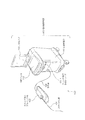
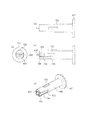
- FIG. 1 is a diagram illustrating an overall configuration of a catheter unit 101.
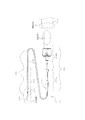
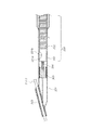
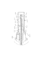
- FIG. FIG. 3 is a diagram illustrating a configuration of a distal end portion of a catheter unit 101. It is sectional drawing which shows the internal structure of a drive shaft connector. It is a partial cross section figure which shows the structure of an optical fiber. It is a figure which shows the internal structure (side connected with the base end of the drive shaft connector 202b) of the attaching part in the scanner / pullback part. It is a figure which shows the external appearance structure of a connector apparatus. It is a figure which shows the external appearance structure of an adapter apparatus.
- FIG. 110 It is a figure which shows operation
- FIG. 110 It is a figure which shows the adapter apparatus housing. It is an external view of a connector device and an adapter device (head 1102). It is sectional drawing of a connector apparatus and an adapter apparatus (head 1102). It is a perspective view of a connector apparatus and an adapter apparatus (head 1102). It is a figure which shows the state of the elastic member before connection of an optical fiber, and a housing fitting part. It is a figure which shows the state of the elastic member at the time of the connection of an optical fiber, and a housing fitting part. It is a figure which shows the state of the elastic member after the connection of an optical fiber, and a housing fitting part. It is a figure which shows the connector apparatus in 2nd Embodiment of the connection apparatus of this invention.
- connection device which is a kind of optical imaging apparatus
- OCT optical coherence tomographic diagnosis apparatus
- other medical devices may be used, and devices other than medical devices may be used.
- FIG. 1 is a diagram showing an external configuration of an optical coherence tomography diagnosis apparatus 100 to which a connection device according to the first embodiment of the present invention is applied.
- the optical coherence tomography diagnosis apparatus 100 includes a catheter unit 101 that is a detachable optical probe, a scanner / pullback unit 102, and an operation control device 103, and controls the scanner / pullback unit 102 and operation.
- the device 103 is connected by a signal line 104.
- the catheter unit 101 is directly inserted into a blood vessel and measures the state inside the blood vessel using low coherence light emitted from an imaging core (see FIGS. 2 and 3).
- the scanner / pullback unit 102 performs radial scanning of the optical imaging core in the catheter unit 101.
- the operation control device 103 has a function for inputting various set values and a function for processing data obtained by measurement and displaying it as a cross-sectional image when performing optical coherence tomography diagnosis.
- reference numeral 111 denotes a main body control unit which processes data obtained by measurement and outputs a processing result.
- Reference numeral 111-1 denotes a printer and a DVD recorder, which print the processing results in the main body control unit 111 or store them as data.
- Reference numeral 113 denotes an LCD monitor that displays a processing result in the main body control unit 111.
- the catheter unit 101 includes a long catheter sheath 201 that is inserted into a blood vessel and a connector unit 202 that is not inserted into the blood vessel and is disposed on the user's hand side for operation by the user. Composed.
- a tube 203 constituting a guide wire lumen is provided at the distal end of the catheter sheath 201.
- the catheter sheath 201 is formed as a continuous lumen from a connection portion with the tube 203 to a connection portion with the connector portion 202. (See FIG. 3 for details).
- an imaging core including an optical transmission / reception unit 221 that transmits and receives measurement light, and a coiled drive shaft 222 that includes an optical fiber cable and transmits a driving force for rotating the optical fiber cable. 220 is inserted through substantially the entire length of the catheter sheath 201.
- the connector section 202 includes a sheath connector 202a configured integrally with the proximal end of the catheter sheath 201 and a drive shaft connector 202b configured to rotatably fix the drive shaft 222 to the proximal end of the drive shaft 222.
- a kink protector 211 is provided at the boundary between the sheath connector 202a and the catheter sheath 201, whereby a predetermined rigidity is maintained, and bending (kink) due to a sudden change in physical properties can be prevented.
- the base end (see FIG. 4 for details) of the drive shaft connector 202b is configured to be connectable to a mounting portion of a scanner / pullback portion 102 (see FIG. 6 for details) described later (the connection device according to this embodiment is a , Applied in the connection of the optical fiber cable between the proximal end of the drive shaft connector 202b and the scanner / pullback portion 102).
- an optical transmission / reception unit 221 includes a prism or mirror 221b and a housing 221a that holds the prism or mirror 221b. Measurement light is irradiated from the prism or mirror 221b toward the tissue in the body cavity, and the prism or mirror 221b is irradiated. The reflected light from the body cavity tissue is received.
- the drive shaft 222 is formed in a coil shape, and an optical fiber cable is disposed in the drive shaft 222 and extends from the optical transmission / reception unit 221 to the connector unit 202.
- the housing 221 a has an optical transmission / reception unit 221 b inside, and the base end side is connected to the drive shaft 222.
- a short coil-shaped elastic member 304 is provided on the tip side.
- the elastic member 304 is a stainless steel wire formed in a coil shape, and the elastic member 304 is arranged on the tip side, so that the stability during rotation of the imaging core 220 is improved.
- 303 is an X-ray contrast coil, which is provided for the purpose of confirming the position of the distal end portion of the catheter sheath 201 in the body under X-ray fluoroscopy.
- the tube 203 defines a hole into which the guide wire 305 can be inserted.
- the guide wire 305 is inserted into the body cavity in advance and used to guide the catheter sheath 201 to the affected area.
- the drive shaft 222 is capable of rotating and sliding with respect to the catheter sheath 201 and is flexible and has a characteristic capable of well transmitting the rotation, for example, by a multi-layered close contact coil made of a metal wire such as stainless steel. It is configured.
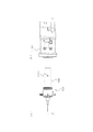
- FIG. 4 is a cross-sectional view showing the internal configuration of the base end of the drive shaft connector 202b.
- an optical fiber connector (second connection terminal) 404 is disposed at the base end of the drive shaft connector 202 b, so that the optical fiber cable 401 is connected to the optical fiber cable in the scanner / pullback unit 102. Connected.
- the connector fixing member 405 aligns the connector 404 in the circumferential direction in cooperation with the first fixing member when coupled to a first connection terminal described later.
- the terminal on the catheter part side is called a “connector”, and the terminal on the other side is called an “adapter”.
- the connector 404 and the connector fixing member 405 are collectively referred to as a connector device.
- the optical fiber connector 404 is joined to the drive shaft 222 via the connection pipe 402.
- the connector 404 is disposed inside a connector fixing member (second fixing member) 405 having a hollow cylindrical shape, and holds and fixes the end of the optical fiber cable 401 provided with a ferrule 406 at the tip. .
- the end portion of the optical fiber cable 401 is processed into an APC type in which an inclination angle is formed with respect to the traveling direction of light in order to prevent noise from being generated by reflection of light at the end surface.
- the connector fixing member 405 has a disk-like flange 407 at the end corresponding to the distal end side of the catheter sheath 201 (the end opposite to the adapter side), and is rotatable inside the housing 408 of the drive shaft connector 202b. Is retained.
- an elastic member 409 is provided in the vicinity of the housing 408 so as to be in contact with the flange 407, and the connection of the optical fiber cable is facilitated by the elastic member 409 pressing the flange 407 at the time of connection with an adapter described later.
- the elastic member 409 and the flange 407 are not in contact with each other, so that damage or deformation of the internal member can be prevented during internal driving.
- the elastic member 409 can be composed of a synthetic rubber or a metal spring. A material such as silicon rubber having low adhesiveness is particularly preferable.
- a pair of convex portions 1101 are formed on the outer surface of the housing 408.
- FIG. 5 is a partial cross-sectional view showing a general configuration of a single mode optical fiber cable.
- the optical fiber cable 401 is composed of a core 501 that transmits light and a clad 502 having a slightly lower refractive index than the core 501, and light is only at the boundary between the core 501 and the clad 502 when the incident angle is larger than the critical angle. The total reflection is repeatedly transmitted on the surface. Further, the outer surface of the clad 502 of the optical fiber 401 is covered with a resin material called a jacket 503 so that the stress is dispersed and the optical fiber cable 401 does not bend even when bent with a large curvature.
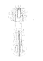
- FIG. 6 is a partial cross-sectional view showing the internal configuration of the attachment portion of the scanner / pullback unit 102 (the side connected to the base end of the drive shaft connector 202b).
- reference numeral 601 denotes a housing of the adapter device provided inside the mounting portion, which is fixed inside the head 1102 constituting the outer surface of the mounting portion.
- the housing 408 of the drive shaft connector 202b is fitted to the inner surface of the housing 601 when the connector is connected.
- the housing 601 is provided with a pair of grooves 1001 that can receive the pair of convex portions 1101 of the housing 408 connected from the groove inlet 1103 of the head 1102.
- the adapter fixing member 603 is joined to a driving force relay pipe 604 that relays the driving force of a rotation driving unit (motor) (not shown), so that after the coupling with the connector 404, the driving force relay pipe 604 is driven to rotate. 222 is transmitted.
- a pair of claws 605 are formed on the inner surface of the adapter fixing member 603.
- the pair of claws 605 are engaged with the connector 404 to firmly integrate the connector 404 and the adapter 602.
- the adapter 602 is formed with a female structure hole 606 for receiving the ferrule 406 of the connector 404, and an optical fiber end portion 607 processed into an APC type is fixed to the back of the hole 606.
- the adapter fixing member 603 includes a protective tube 608 that defines the outer surface, and a guide tube 609 that is fixed to the inner surface of the protective tube 608 and defines the inner surface of the adapter fixing member 603.
- the housing 601, the adapter 602, and the adapter fixing member 603 are collectively referred to as an adapter device. That is, the connection device is constituted by a connector device and an adapter device.
- connection device according to the present embodiment will be described.
- FIG. 7 is a diagram showing an external configuration of the connector device, where (a) is a front view, (b) is a top view, (c) is a side view, and (d) is a perspective view. is there.
- the connector device includes a connector fixing member 405 having a hollow cylindrical shape, and a connector 404 arranged inside the connector fixing member 405.
- Reference numeral 406 denotes a ferrule formed at the end of the connector 404.
- a convex portion 702 is formed in the longitudinal direction on a part of the outer peripheral surface of the connector fixing member 405.
- the proximal end portion of the convex portion 702 is a sharp end portion in order to reduce contact resistance with an end surface of an adapter fixing member 603 described later.
- the connector fixing member 405 has an outer diameter R so that the outer peripheral surface of the connector fixing member 405 slides with respect to the inner wall surface of the adapter fixing member 603 when inserted into the hollow of the adapter fixing member 603. It has been.
- a pair of slits 703 are formed at positions that do not interfere with the convex portions 702 on the outer peripheral surface of the connector fixing member 405 so as to be symmetrical.
- the side surfaces of the connectors 404 are exposed inside the slits 703, and convex portions 704 that engage with the claws 605 of the adapter fixing member 603 are formed therein.
- the connector fixing member 405 When the connector 404, the adapter 602, and the adapter fixing member 603 are integrated by the claw 605 and the convex portion 704, the connector fixing member 405 is not involved in the connection therebetween, and the connector fixing member 405 is slightly slid back and forth in the axial direction. It has a movable configuration.
- the connector fixing member 405 slides in the pulling direction via the flange 407, and at that time The round projection 705 formed at the base end of the slit 703 spreads the claw 605, releases the engagement with the convex portion 704, and can pull out the connector 404 from the adapter 602.
- FIGS. 8A and 8B are diagrams showing the external configuration of the guide tube 609 of the adapter device, where FIG. 8A is a top view, FIG. 8B is a side view, and FIG. 8C is a front view.
- the adapter device includes the adapter fixing member 603 having a hollow cylindrical shape, the adapter 602 fixed inside the adapter fixing member 603, and the housing 601.
- the adapter fixing member 603 includes a protective tube 608 and a guide tube 609. In FIG. 8, however, the structure of the guide tube 609 is illustrated alone.
- the protective tube 608 is provided for the purpose of covering the sharp tip of the guide tube 609, preventing injury to the user and damage to the connector 404, and guiding the fixing member 405 to be inserted into the guide tube 609.
- the protective tube 608 and the guide tube 609 may be molded integrally. As shown in FIG. 8, end surfaces 801 ⁇ / b> A and 801 ⁇ / b> B that are inclined end surfaces are formed on the open side of the guide tube 609.
- a notch portion 802 extending in the longitudinal direction of the adapter fixing member 603 (the axial direction of the hollow portion) is provided in a part of the end surfaces 801A and 801B of the guide tube 609. Yes.
- the notch 802 is designed with a circumferential width w so that the convex portion 702 of the connector fixing member 405 is fitted.
- the end surface 801A is an end surface extending clockwise in the circumferential direction starting from the notch 802, and the end surface 801B is an end surface extending counterclockwise.
- the end surface 801A and the end surface 801B intersect at a position of 180 degrees in the circumferential direction when viewed from the notch 802 (hereinafter, this position is referred to as a vertex).
- the end surface 801A and the end surface 801B have a symmetric relationship with respect to a plane including the notch 802 and the apex.
- the end surface 801A includes an outer wall boundary line 801A-1 that is a boundary with the outer wall and an inner wall boundary line 801A-2 that is a boundary with the inner wall.
- the end surface 801B includes an outer wall boundary line 801B-1 that is a boundary with the outer wall and an inner wall boundary line 801B-2 that is a boundary with the inner wall.
- the outer wall boundary line 801A-1 rotates 180 degrees clockwise in the circumferential direction so as to draw a spiral shape starting from the notch 802, and intersects the outer wall boundary line 801B-1 at the apex.
- the outer wall boundary line 801B-1 starts from the notch 802 and rotates 180 degrees counterclockwise in the circumferential direction so as to draw a spiral shape, and intersects the outer wall boundary line 801A-1 at the apex.
- the inner wall boundary line 801A-2 starts from the notch 802 and rotates 180 degrees clockwise in the circumferential direction so as to draw a spiral shape, and intersects the inner wall boundary line 801B-2 at the apex.
- the inner wall boundary line 801B-2 starts from the notch 802 and rotates 180 degrees in the circumferential direction so as to draw a spiral shape, and intersects the inner wall boundary line 801A-2 at the apex.
- the spiral pitches of the outer wall boundary line and the inner wall boundary line are equal.
- FIGS. 9A to 9D are views showing the operation of the connector fixing member 405 and the adapter fixing member 603 when connecting the connection device.
- the drive shaft connector 202b, the housing 601, and the protective tube 608 are omitted for the sake of explanation.
- FIG. 9 (a) when connecting, first, the drive shaft connector 202 b (not shown) is gripped, and the distal end portion of the connector fixing member 405 is inserted into the hollow portion of the adapter fixing member 603 at an arbitrary circumferential angle. To do.
- the connector fixing member 405 when the connector fixing member 405 is pressed in the insertion direction, the connector fixing member 405 further rotates. Eventually, when the convex portion 702 reaches the position of the notch portion 802, the convex portion 702 is fitted into the notch portion 802 (that is, the convex portion 702 becomes the notch portion 802 only by pressing the connector fixing member 405. Will be guided). When the connector fixing member 405 is further pushed in, the convex portion 702 is inserted straight along the notch 802, and the adapter 602 and the connector 404 are coupled.
- the tip of the convex portion 702 is fitted into the notch 802
- the circumferential movement of the connector fixing member 405 is restricted (that is, the alignment in the circumferential direction is completed), and the convex portion 702 Is inserted along the notch 802 to realize the coupling between the adapter 602 and the connector 404.
- the connector fixing member 405 is inserted into the hollow portion of the adapter fixing member 603, the connector fixing member 405 is inserted.
- the convex portion 702 is automatically guided toward the notch portion 802, and the connector fixing member 405 completes the desired alignment in the circumferential direction.
- the connecting device for connecting the optical fiber cable it is possible to easily perform the alignment in the circumferential direction for connecting the connectors. That is, the user simply moves the housing 408 of the drive shaft connector 202b linearly in the insertion direction, and the connector fixing member 405 is automatically aligned in the circumferential direction, and the desired alignment is completed.
- FIG. 10 shows a housing 601 that is a component inside the head 1102 of the mounting portion, where (a) is a top view and (b) is a perspective view.
- the housing 601 is provided with a pair of grooves 1001 at positions symmetrical with respect to the axis of the cylindrical main body.
- Each of the two groove portions 1001 is fitted with a later-described convex portion 1101 provided on the housing 408 of the connector device through the groove portion inlet 1002.
- the groove portion 1001 is inserted into the groove portion 1001, and the connector fixing member 405 is further urged in the insertion direction so that the protrusion portion 1101 is moved toward the groove portion 1001.
- the end of the groove 1001 is reached and stopped, and the adapter 602 and the connector 404 are coupled. That is, the groove part 1001 is formed so that the convex part 1101 proceeds in a rotation direction perpendicular to the insertion direction after making a U-turn from the insertion direction.
- the groove portion 1001 does not penetrate through the groove portion inlet 1002 and penetrates in the inner region, but is not limited thereto.
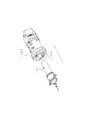
- FIG. 11A and 11B are external views of the connector device and the adapter device covered with the head 1102.
- FIG. 11A is a side view of the connector unit 202
- FIG. 11B is a side view of the adapter device (head 1102).
- 12 is a cross-sectional view taken along the line AA in FIG. 11, and
- FIG. 13 is a perspective view showing a state when the connector 202 and the adapter device (head 1102 are connected).
- a convex portion 1101 is arranged on the housing 408 of the connector device, and a housing 601 of the adapter device is arranged in the head 1102 of the adapter device.
- a groove portion inlet 1103 that is continuous with the groove portion 1001 of the housing 601 is provided at the inlet portion of the head 1102. That is, when the head 1102 and the connector device housing 408 are fitted together, the groove portion inlet 1103 disposed on the head 1102 and the groove portion 1001 disposed on the connector device housing 408 are positioned at the same place in the circumferential direction. To do.
- FIGS. 14 to 16 (a) is an external view showing a state in which the convex portion 1101 of the connector device housing 408 is inserted into the groove portion 1001 of the adapter device housing 601, and (b) is the connector device housing.
- the state of the elastic member when the convex portion 1101 of 408 is inserted into the groove portion 1001 of the adapter device housing 601 is shown. Note that the head 1102 is not shown for easy understanding.
- FIGS. 14A and 14B when connecting, first, the convex portion 1101 is inserted into the groove portion 1001. Next, as shown in FIG.
- the optical fiber connector is firmly connected by the elastic force of the elastic member 409, and the connector device and the adapter device are fitted to each other. be able to.
- the elastic member 409 functions as a pusher while being compressed, the optical fiber connector is not pushed excessively to be damaged, and the push-in is insufficient to cause a connection failure.
- the connector device moves slightly in the direction away from the adapter device, so that the elastic member 409 functioning as a pusher is separated from the flange 407 as a rotor, so that the rotor is Even if it rotates at high speed, it will not be damaged by contact with a non-rotating member. Therefore, the connector for the optical fiber can be easily connected.
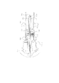
- FIG. 17 is a view showing a connector device according to a second embodiment of the connection device of the present invention.
- the elastic member 409 that presses the disk-shaped flange 407 when the optical fiber cable is connected is a metal coil spring 1701.
- the coil spring 1701 has a cylindrical pusher 1702 at its end, and the pusher 1702 presses the disc-shaped flange 407 so that an optical fiber is connected.
- any material for forming the coil spring 1701 any material can be used as long as it can exhibit elasticity.
Landscapes
- Physics & Mathematics (AREA)
- General Physics & Mathematics (AREA)
- Optics & Photonics (AREA)
- Mechanical Coupling Of Light Guides (AREA)
- Endoscopes (AREA)
Abstract
Provided is a connection device which for connecting optical fiber cables, wherein contact with the internal parts is reduced when connecting a connector, and the connection is simplified. When a projection (1101) of a connector device housing is slid along a groove (1001) and is positioned at the deepest part of the groove (1001) during the insertion of the projection (1101) into an adapter device groove (1001) of an adapter device housing (601), the connection device which connects optical fiber cables compresses an elastic member, and connects an optical fiber connector of the connector device and the optical fiber end on the adapter device side.
Description
本発明は、光ファイバーケーブルを接続するための接続装置ならびにその構成部材に関するものである。
The present invention relates to a connection device for connecting an optical fiber cable and its constituent members.
近年、大容量通信などの発達により、通信分野を中心に光ファイバーケーブルを接続するための接続装置として光ファイバー用のコネクタの需要が高まってきている。光ファイバー用のコネクタの具体例としては、例えば、FCコネクタやSCコネクタ、MUコネクタ等が挙げられる。
In recent years, with the development of large-capacity communication and the like, the demand for optical fiber connectors as connection devices for connecting optical fiber cables is increasing mainly in the communication field. Specific examples of optical fiber connectors include FC connectors, SC connectors, MU connectors, and the like.
これらのコネクタには、接続された光ファイバーケーブルの端部(接触面)同士の傷つきを防止すべく、光ファイバーケーブル間の相対的な回動を回避するための機構が備えられている。例えば、FCコネクタの場合、ピンと溝により周方向の回動を回避し、SCコネクタ、MUコネクタの場合、コネクタの各形状を利用して周方向の回動を回避している(例えば、下記特許文献1、2参照)。
These connectors are provided with a mechanism for avoiding relative rotation between the optical fiber cables in order to prevent the ends (contact surfaces) of the connected optical fiber cables from being damaged. For example, in the case of an FC connector, circumferential rotation is avoided by pins and grooves, and in the case of an SC connector and MU connector, circumferential rotation is avoided by using each shape of the connector (for example, the following patents) References 1 and 2).
一方、このような機構を有するが故に、ユーザはコネクタ結合時に周方向の位置合わせを行うことが必要となってくる。特に、反射ノイズを押えるために光ファイバーケーブル端部に傾斜角度が設けられたAPCタイプのコネクタにあっては、より高い精度での位置合わせが要求されることとなる(例えば、下記特許文献3参照)。
On the other hand, since it has such a mechanism, it is necessary for the user to perform alignment in the circumferential direction when the connector is coupled. In particular, in an APC type connector in which an inclination angle is provided at the end of an optical fiber cable in order to suppress reflection noise, alignment with higher accuracy is required (for example, see Patent Document 3 below). ).
一方、近年、医療分野においても、光干渉断層診断装置(OCT)をはじめとして、光を利用した各種医療装置が増えてきている。これらの医療装置は、光を信号として利用し、信号の伝送には光ファイバーケーブルを用いている。このため、光ファイバーケーブルを接続するための光ファイバー用のコネクタの使用が不可欠となっている(例えば、下記特許文献4参照)。
On the other hand, in recent years, in the medical field, various medical devices using light such as an optical coherence tomography diagnostic device (OCT) are increasing. These medical devices use light as a signal and use an optical fiber cable for signal transmission. For this reason, it is indispensable to use an optical fiber connector for connecting an optical fiber cable (for example, see Patent Document 4 below).
本発明の目的は、このような問題点に鑑みてなされ、光ファイバーケーブルを接続するための接続装置において、コネクタ接続時の内部部材の接触を低減し、接続を容易に行えるようにするものである。
An object of the present invention is made in view of such problems, and in a connection device for connecting an optical fiber cable, the contact of an internal member at the time of connector connection is reduced and the connection can be easily performed. .
このような目的は、下記(1)から(6)の本発明により達成される。
Such an object is achieved by the present invention described in (1) to (6) below.
(1)光ファイバーケーブルを接続する接続装置であって、アダプタ装置内部に第1接続端子が配され、端部が開放された中空部を有する第1固定部材と、コネクタ装置内部に第2接続端子が配され、前記第1固定部材内に挿入した場合、前記第1固定部材の内壁に沿って摺動するようにその外壁が形成された第2固定部材と、を備え、前記アダプタ装置のハウジングは少なくとも一つの曲線状の溝部を備え、前記コネクタ装置のハウジングの外壁の一部に少なくとも一つの凸部を備え、前記第2固定部材の基端側に弾性部材を更に備え、前記溝部は、前記第2固定部材を前記第1固定部材内に挿入した場合に前記凸部が前記溝部に挿入され、前記第2固定部材を更に挿入方向に付勢することで、前記凸部が前記溝部を摺動し、前記凸部が前記挿入方向と逆方向に戻る動作の後に停止し、前記第1接続端子と前記第2接続端子とが結合するように構成されていることを特徴とする特徴とする接続装置。
(1) A connection device for connecting an optical fiber cable, in which a first connection terminal is arranged inside the adapter device, and has a hollow portion with an open end, and a second connection terminal inside the connector device. And a second fixing member having an outer wall formed so as to slide along the inner wall of the first fixing member when inserted into the first fixing member, the housing of the adapter device Comprises at least one curved groove, at least one projection on a part of the outer wall of the housing of the connector device, further comprising an elastic member on the base end side of the second fixing member, and the groove When the second fixing member is inserted into the first fixing member, the convex portion is inserted into the groove portion, and the second fixing member is further urged in the insertion direction so that the convex portion causes the groove portion to be inserted. Sliding, the convex part Serial stopped after the insertion direction and return to the reverse operation, connection and wherein, characterized in that said first connecting terminal and the second connecting terminal is configured to couple device.
(2)前記第2固定部材は円盤状フランジを更に備え、前記凸部が前記溝部に沿って挿入されることで、前記弾性部材が前記円盤状フランジを押圧し、前記第1接続端子と前記第2接続端子とが結合するように構成されていることを特徴とする上記(1)に記載の接続装置。
(2) The second fixing member further includes a disc-shaped flange, and the elastic member presses the disc-shaped flange when the convex portion is inserted along the groove portion, and the first connection terminal and the The connection device according to (1), wherein the connection device is configured to be coupled to the second connection terminal.
(3)前記溝部は、前記第1接続端子と前記第2接続端子との結合後に前記凸部が前記挿入方向と逆方向に戻る動作の後に停止した際に、前記円盤状フランジが前記弾性部材と非接触となるように構成されていることを特徴とする上記(1)に記載の接続装置。
(3) When the groove portion stops after the convex portion is returned to the direction opposite to the insertion direction after the first connection terminal and the second connection terminal are coupled, the disk-like flange is the elastic member. It is comprised so that it may become non-contact with, The connection apparatus as described in said (1) characterized by the above-mentioned.
(4)前記溝部は、前記凸部が前記挿入方向からUターンした後、前記挿入方向に対して垂直な回転方向に進むよう構成されていることを特徴とする上記(1)に記載の接続装置。
(4) The connection according to (1), wherein the groove is configured to advance in a rotation direction perpendicular to the insertion direction after the convex portion makes a U-turn from the insertion direction. apparatus.
(5)前記弾性部材が樹脂または金属部材であることを特徴とする上記(1)に記載の接続装置
(6)上記(1)に記載の接続装置を備えた光イメージング装置であって、光ファイバーを回転自在に内蔵した光プローブと、光源を有し前記プローブに対し、信号の送受信を行う制御装置と、
前記光プローブと前記制御装置を接続する、前記接続装置を有することを特徴とする光イメージング装置。 (5) The connection device according to (1), wherein the elastic member is a resin or a metal member. (6) An optical imaging device including the connection device according to (1), wherein an optical fiber is provided. An optical probe that is rotatably incorporated, a control device that has a light source and transmits and receives signals to and from the probe,
An optical imaging apparatus comprising the connection device for connecting the optical probe and the control device.
本発明によれば、光ファイバーケーブルを接続するための接続装置において、コネクタ接続時に部材を破損することがなく、確実に接続され、また接続後の内部駆動時に内部部材の接触を低減することができる。
According to the present invention, in the connection device for connecting the optical fiber cable, the member is not damaged when the connector is connected, and the connection is ensured, and the contact of the internal member can be reduced during the internal driving after the connection. .
以下、必要に応じて添付図面を参照しながら本発明の各実施形態を詳細に説明する。なお、以下の各実施形態では、本発明にかかる接続装置を光イメージング装置の一種である光干渉断層診断装置(OCT)に適用した場合について説明するが、本発明の適用対象はこれに限られるものではなく、他の医療装置であってもよいし、また、医療装置以外の装置であってもよいことはいうまでもない。
Hereinafter, each embodiment of the present invention will be described in detail with reference to the accompanying drawings as necessary. In each of the following embodiments, a case where the connection device according to the present invention is applied to an optical coherence tomographic diagnosis apparatus (OCT) which is a kind of optical imaging apparatus will be described, but the scope of application of the present invention is limited to this. Needless to say, other medical devices may be used, and devices other than medical devices may be used.
1.光干渉断層診断装置の外観構成
図1は本発明の第1の実施形態にかかる接続装置が適用された光干渉断層診断装置100の外観構成を示す図である。 1. FIG. 1 is a diagram showing an external configuration of an optical coherencetomography diagnosis apparatus 100 to which a connection device according to the first embodiment of the present invention is applied.
図1は本発明の第1の実施形態にかかる接続装置が適用された光干渉断層診断装置100の外観構成を示す図である。 1. FIG. 1 is a diagram showing an external configuration of an optical coherence
図1に示すように、光干渉断層診断装置100は、着脱可能な光プローブであるカテーテル部101と、スキャナ/プルバック部102と、操作制御装置103とを備え、スキャナ/プルバック部102と操作制御装置103とは、信号線104により接続されている。
As shown in FIG. 1, the optical coherence tomography diagnosis apparatus 100 includes a catheter unit 101 that is a detachable optical probe, a scanner / pullback unit 102, and an operation control device 103, and controls the scanner / pullback unit 102 and operation. The device 103 is connected by a signal line 104.
カテーテル部101は、直接血管内に挿入され、イメージングコア(図2、図3参照)より照射される低干渉性光を用いて血管内部の状態を測定する。スキャナ/プルバック部102は、カテーテル部101内の光イメージングコアのラジアル走査を実行する。
The catheter unit 101 is directly inserted into a blood vessel and measures the state inside the blood vessel using low coherence light emitted from an imaging core (see FIGS. 2 and 3). The scanner / pullback unit 102 performs radial scanning of the optical imaging core in the catheter unit 101.
操作制御装置103は、光干渉断層診断を行うにあたり、各種設定値を入力するための機能や、測定により得られたデータを処理し、断面画像として表示するための機能を備える。
The operation control device 103 has a function for inputting various set values and a function for processing data obtained by measurement and displaying it as a cross-sectional image when performing optical coherence tomography diagnosis.
操作制御装置103において、111は本体制御部であり、測定により得られたデータを処理したり、処理結果を出力する。111-1はプリンタ及びDVDレコーダであり、本体制御部111における処理結果を印刷したり、データとして記憶したりする。
In the operation control device 103, reference numeral 111 denotes a main body control unit which processes data obtained by measurement and outputs a processing result. Reference numeral 111-1 denotes a printer and a DVD recorder, which print the processing results in the main body control unit 111 or store them as data.
112は操作パネルであり、ユーザは操作パネル112を介して、各種設定値の入力を行う。113はLCDモニタであり、本体制御部111における処理結果を表示する。
112 is an operation panel, and the user inputs various setting values via the operation panel 112. Reference numeral 113 denotes an LCD monitor that displays a processing result in the main body control unit 111.
2.カテーテル部101の構成
2.1 カテーテル部101の全体構成
次にカテーテル部101の全体構成について図2を用いて説明する。図2に示すように、カテーテル部101は、血管内に挿入される長尺のカテーテルシース201と、ユーザが操作するために血管内に挿入されずユーザの手元側に配置されるコネクタ部202により構成される。カテーテルシース201の先端には、ガイドワイヤルーメンを構成するチューブ203が設けられており、カテーテルシース201は、チューブ203との接続部分からコネクタ部202との接続部分にかけて連続する管腔として形成されている(なお、詳細は図3参照)。 2. 2. Configuration ofCatheter Unit 101 2.1 Overall Configuration of Catheter Unit 101 Next, the overall configuration of the catheter unit 101 will be described with reference to FIG. As shown in FIG. 2, the catheter unit 101 includes a long catheter sheath 201 that is inserted into a blood vessel and a connector unit 202 that is not inserted into the blood vessel and is disposed on the user's hand side for operation by the user. Composed. A tube 203 constituting a guide wire lumen is provided at the distal end of the catheter sheath 201. The catheter sheath 201 is formed as a continuous lumen from a connection portion with the tube 203 to a connection portion with the connector portion 202. (See FIG. 3 for details).
2.1 カテーテル部101の全体構成
次にカテーテル部101の全体構成について図2を用いて説明する。図2に示すように、カテーテル部101は、血管内に挿入される長尺のカテーテルシース201と、ユーザが操作するために血管内に挿入されずユーザの手元側に配置されるコネクタ部202により構成される。カテーテルシース201の先端には、ガイドワイヤルーメンを構成するチューブ203が設けられており、カテーテルシース201は、チューブ203との接続部分からコネクタ部202との接続部分にかけて連続する管腔として形成されている(なお、詳細は図3参照)。 2. 2. Configuration of
カテーテルシース201の管腔内部には、測定光を送受信する光送受信部221と、光ファイバーケーブルを内部に備え、それを回転させるための駆動力を伝達するコイル状の駆動シャフト222とを備えるイメージングコア220がカテーテルシース201のほぼ全長にわたって挿通されている。
In the lumen of the catheter sheath 201, an imaging core including an optical transmission / reception unit 221 that transmits and receives measurement light, and a coiled drive shaft 222 that includes an optical fiber cable and transmits a driving force for rotating the optical fiber cable. 220 is inserted through substantially the entire length of the catheter sheath 201.
コネクタ部202は、カテーテルシース201の基端に一体化して構成されたシースコネクタ202aと駆動シャフト222の基端に駆動シャフト222を回転可能に固定して構成された駆動シャフトコネクタ202bとからなる。
The connector section 202 includes a sheath connector 202a configured integrally with the proximal end of the catheter sheath 201 and a drive shaft connector 202b configured to rotatably fix the drive shaft 222 to the proximal end of the drive shaft 222.
シースコネクタ202aとカテーテルシース201の境界部には、耐キンクプロテクタ211が設けられている、これにより所定の剛性が保たれ、急激な物性の変化による折れ曲がり(キンク)を防止することができる。
A kink protector 211 is provided at the boundary between the sheath connector 202a and the catheter sheath 201, whereby a predetermined rigidity is maintained, and bending (kink) due to a sudden change in physical properties can be prevented.
駆動シャフトコネクタ202bの基端(詳細は図4参照)は、後述するスキャナ/プルバック部102(詳細は図6参照)の取付部と接続可能に構成されている(本実施形態にかかる接続装置は、駆動シャフトコネクタ202bの基端と、スキャナ/プルバック部102との間の光ファイバーケーブルの接続において適用されている)。
The base end (see FIG. 4 for details) of the drive shaft connector 202b is configured to be connectable to a mounting portion of a scanner / pullback portion 102 (see FIG. 6 for details) described later (the connection device according to this embodiment is a , Applied in the connection of the optical fiber cable between the proximal end of the drive shaft connector 202b and the scanner / pullback portion 102).
2.2 カテーテル部101の先端部の構成
次にカテーテル部101の先端部の構成について図3を用いて説明する。 2.2 Configuration of the distal end portion of thecatheter portion 101 Next, the configuration of the distal end portion of the catheter portion 101 will be described with reference to FIG.
次にカテーテル部101の先端部の構成について図3を用いて説明する。 2.2 Configuration of the distal end portion of the
図3において、光送受信部221は、プリズムまたはミラー221bとそれを保持するハウジング221aからなり、当該プリズムまたはミラー221bより体腔内組織に向けて測定光が照射されるとともに、当該プリズムまたはミラー221bにて体腔内組織からの反射光を受ける。
In FIG. 3, an optical transmission / reception unit 221 includes a prism or mirror 221b and a housing 221a that holds the prism or mirror 221b. Measurement light is irradiated from the prism or mirror 221b toward the tissue in the body cavity, and the prism or mirror 221b is irradiated. The reflected light from the body cavity tissue is received.
駆動シャフト222はコイル状に形成され、その内部には光ファイバーケーブルが配され、光送受信部221からコネクタ部202まで伸びている。
The drive shaft 222 is formed in a coil shape, and an optical fiber cable is disposed in the drive shaft 222 and extends from the optical transmission / reception unit 221 to the connector unit 202.
ハウジング221aは、内部に光送受信部221bを有し、基端側は駆動シャフト222と接続されている。また、先端側には短いコイル状の弾性部材304が設けられている。
The housing 221 a has an optical transmission / reception unit 221 b inside, and the base end side is connected to the drive shaft 222. A short coil-shaped elastic member 304 is provided on the tip side.
弾性部材304はステンレス鋼線材をコイル状に形成したものであり、弾性部材304が先端側に配されることで、イメージングコア220の回転時の安定性が向上する。
The elastic member 304 is a stainless steel wire formed in a coil shape, and the elastic member 304 is arranged on the tip side, so that the stability during rotation of the imaging core 220 is improved.
303はX線造影コイルであり、体内におけるカテーテルシース201の先端部の位置をX線透視下で確認する目的で設けられている。
303 is an X-ray contrast coil, which is provided for the purpose of confirming the position of the distal end portion of the catheter sheath 201 in the body under X-ray fluoroscopy.
チューブ203は、ガイドワイヤ305が挿入可能な孔を規定する。ガイドワイヤ305は、予め体腔内に挿入され、カテーテルシース201を患部まで導くために使用される。
The tube 203 defines a hole into which the guide wire 305 can be inserted. The guide wire 305 is inserted into the body cavity in advance and used to guide the catheter sheath 201 to the affected area.
駆動シャフト222は、カテーテルシース201に対して回転及びスライド動作することが可能であり、柔軟で、かつ回転をよく伝達できる特性をもつ、例えば、ステンレス等の金属線からなる多重多層密着コイル等により構成されている。
The drive shaft 222 is capable of rotating and sliding with respect to the catheter sheath 201 and is flexible and has a characteristic capable of well transmitting the rotation, for example, by a multi-layered close contact coil made of a metal wire such as stainless steel. It is configured.
2.3 駆動シャフトコネクタ202bの構成
図4は駆動シャフトコネクタ202bの基端の内部構成を示す断面図である。図4に示すように、駆動シャフトコネクタ202bの基端には、光ファイバー用のコネクタ(第2接続端子)404が配されており、これにより光ファイバーケーブル401はスキャナ/プルバック部102内の光ファイバーケーブルと接続される。 2.3 Configuration ofDrive Shaft Connector 202b FIG. 4 is a cross-sectional view showing the internal configuration of the base end of the drive shaft connector 202b. As shown in FIG. 4, an optical fiber connector (second connection terminal) 404 is disposed at the base end of the drive shaft connector 202 b, so that the optical fiber cable 401 is connected to the optical fiber cable in the scanner / pullback unit 102. Connected.
図4は駆動シャフトコネクタ202bの基端の内部構成を示す断面図である。図4に示すように、駆動シャフトコネクタ202bの基端には、光ファイバー用のコネクタ(第2接続端子)404が配されており、これにより光ファイバーケーブル401はスキャナ/プルバック部102内の光ファイバーケーブルと接続される。 2.3 Configuration of
コネクタ固定部材405は、後述する第1接続端子との結合に際して第1固定部材と協働してコネクタ404の周方向の位置合わせを行う。なお、本実施形態においては、便宜上、カテーテル部側の端子を「コネクタ」、他方側の端子を「アダプタ」と呼ぶ。また、以下では、コネクタ404とコネクタ固定部材405とを合わせてコネクタ装置と称す。
The connector fixing member 405 aligns the connector 404 in the circumferential direction in cooperation with the first fixing member when coupled to a first connection terminal described later. In the present embodiment, for convenience, the terminal on the catheter part side is called a “connector”, and the terminal on the other side is called an “adapter”. Hereinafter, the connector 404 and the connector fixing member 405 are collectively referred to as a connector device.
光ファイバー用のコネクタ404は、接続パイプ402を介して駆動シャフト222と接合されている。また、コネクタ404は、中空の円筒形状をしたコネクタ固定部材(第2固定部材)405の内部に配置されており、先端にフェルール406が設けられた光ファイバーケーブル401の端部を保持固定している。光ファイバーケーブル401の端部は端面での光の反射によりノイズが発生することを防ぐため、光の進行方向に対して、傾斜角度が形成されたAPCタイプに加工されている。コネクタ固定部材405は、カテーテルシース201の先端側にあたる端部(アダプタ側と反対側の端部)に円盤状のフランジ407を有しており、駆動シャフトコネクタ202bのハウジング408内部に、回転自在に保持されている。
The optical fiber connector 404 is joined to the drive shaft 222 via the connection pipe 402. The connector 404 is disposed inside a connector fixing member (second fixing member) 405 having a hollow cylindrical shape, and holds and fixes the end of the optical fiber cable 401 provided with a ferrule 406 at the tip. . The end portion of the optical fiber cable 401 is processed into an APC type in which an inclination angle is formed with respect to the traveling direction of light in order to prevent noise from being generated by reflection of light at the end surface. The connector fixing member 405 has a disk-like flange 407 at the end corresponding to the distal end side of the catheter sheath 201 (the end opposite to the adapter side), and is rotatable inside the housing 408 of the drive shaft connector 202b. Is retained.
また、ハウジング408内にはフランジ407と接触可能な近傍に弾性部材409を備えており、後述するアダプタとの接続時に弾性部材409がフランジ407を押圧することで光ファイバーケーブルの接続を容易にする。また、光ファイバーケーブルの接続後は、弾性部材409と前記フランジ407は非接触となるため、内部駆動時に内部部材の破損や変形を防ぐことができる。弾性部材409は合成ゴムや金属バネによって構成することができる。粘着性の低いシリコンゴムなどの材料が特に好ましい。
Also, an elastic member 409 is provided in the vicinity of the housing 408 so as to be in contact with the flange 407, and the connection of the optical fiber cable is facilitated by the elastic member 409 pressing the flange 407 at the time of connection with an adapter described later. In addition, after the optical fiber cable is connected, the elastic member 409 and the flange 407 are not in contact with each other, so that damage or deformation of the internal member can be prevented during internal driving. The elastic member 409 can be composed of a synthetic rubber or a metal spring. A material such as silicon rubber having low adhesiveness is particularly preferable.
ハウジング408の外表面には一対の凸部1101が形成されている。
A pair of convex portions 1101 are formed on the outer surface of the housing 408.
2.4 光ファイバーケーブル401の構成
図5は、シングルモード光ファイバーケーブルの一般的な構成を示す一部断面図である。光ファイバーケーブル401は、光を伝送するコア501と、コア501よりも屈折率のやや小さいクラッド502より構成され、入射角が臨界角よりも大きい場合にのみ、光がコア501とクラッド502との境界面で全反射を繰り返し伝送される。また、光ファイバー401のクラッド502の外面はジャケット503と呼ばれる樹脂材料で被覆されており、大きな曲率で曲げた場合においても、応力が分散され、光ファイバーケーブル401が折れたりしないようになっている。 2.4 Configuration ofOptical Fiber Cable 401 FIG. 5 is a partial cross-sectional view showing a general configuration of a single mode optical fiber cable. The optical fiber cable 401 is composed of a core 501 that transmits light and a clad 502 having a slightly lower refractive index than the core 501, and light is only at the boundary between the core 501 and the clad 502 when the incident angle is larger than the critical angle. The total reflection is repeatedly transmitted on the surface. Further, the outer surface of the clad 502 of the optical fiber 401 is covered with a resin material called a jacket 503 so that the stress is dispersed and the optical fiber cable 401 does not bend even when bent with a large curvature.
図5は、シングルモード光ファイバーケーブルの一般的な構成を示す一部断面図である。光ファイバーケーブル401は、光を伝送するコア501と、コア501よりも屈折率のやや小さいクラッド502より構成され、入射角が臨界角よりも大きい場合にのみ、光がコア501とクラッド502との境界面で全反射を繰り返し伝送される。また、光ファイバー401のクラッド502の外面はジャケット503と呼ばれる樹脂材料で被覆されており、大きな曲率で曲げた場合においても、応力が分散され、光ファイバーケーブル401が折れたりしないようになっている。 2.4 Configuration of
3. スキャナ/プルバック部102の内部構成
図6はスキャナ/プルバック部102の取付部の内部構成(駆動シャフトコネクタ202bの基端と接続される側)を示す部分断面図である。図6において、601は取付部の内部に設けられたアダプタ装置のハウジングであり、取付部の外表面を構成するヘッド1102の内部に固定されている。ハウジング601の内面には、コネクタ接続時に駆動シャフトコネクタ202bのハウジング408が嵌合する。ハウジング601には、ヘッド1102の溝部入口1103からつながる、ハウジング408の一対の凸部1101を受け入れ可能な一対の溝部1001が設けられている。 3. FIG. 6 is a partial cross-sectional view showing the internal configuration of the attachment portion of the scanner / pullback unit 102 (the side connected to the base end of thedrive shaft connector 202b). In FIG. 6, reference numeral 601 denotes a housing of the adapter device provided inside the mounting portion, which is fixed inside the head 1102 constituting the outer surface of the mounting portion. The housing 408 of the drive shaft connector 202b is fitted to the inner surface of the housing 601 when the connector is connected. The housing 601 is provided with a pair of grooves 1001 that can receive the pair of convex portions 1101 of the housing 408 connected from the groove inlet 1103 of the head 1102.
図6はスキャナ/プルバック部102の取付部の内部構成(駆動シャフトコネクタ202bの基端と接続される側)を示す部分断面図である。図6において、601は取付部の内部に設けられたアダプタ装置のハウジングであり、取付部の外表面を構成するヘッド1102の内部に固定されている。ハウジング601の内面には、コネクタ接続時に駆動シャフトコネクタ202bのハウジング408が嵌合する。ハウジング601には、ヘッド1102の溝部入口1103からつながる、ハウジング408の一対の凸部1101を受け入れ可能な一対の溝部1001が設けられている。 3. FIG. 6 is a partial cross-sectional view showing the internal configuration of the attachment portion of the scanner / pullback unit 102 (the side connected to the base end of the
602はコネクタ404と結合されるアダプタ(第1接続端子)であり、ハウジング601に対し相対回転可能に保持されている。603は中空の円筒形状をしており、内部にアダプタ602が相対回転不可能なように固定されたアダプタ固定部材(第1固定部材)であり、コネクタ404との結合に際してコネクタ固定部材405と協働してコネクタ404の周方向の位置合わせを行う。アダプタ固定部材603は図示しない回転駆動部(モータ)の駆動力を中継する駆動力中継パイプ604に接合されており、これによりコネクタ404との結合後、駆動力中継パイプ604の回転駆動が駆動シャフト222に伝達される。
602 is an adapter (first connection terminal) coupled to the connector 404 and is held so as to be rotatable relative to the housing 601. Reference numeral 603 denotes a hollow cylindrical shape, which is an adapter fixing member (first fixing member) in which the adapter 602 is fixed so as not to be relatively rotatable, and cooperates with the connector fixing member 405 when coupled to the connector 404. It works to align the connector 404 in the circumferential direction. The adapter fixing member 603 is joined to a driving force relay pipe 604 that relays the driving force of a rotation driving unit (motor) (not shown), so that after the coupling with the connector 404, the driving force relay pipe 604 is driven to rotate. 222 is transmitted.
アダプタ固定部材603の内表面には一対の爪605が形成されている。一対の爪605は、コネクタ404と係合し、コネクタ404とアダプタ602とを強固に一体化するものである。アダプタ602には、コネクタ404のフェルール406を受け入れるメス型構造の穴606が形成され、穴606の奥にAPCタイプに加工された光ファイバー端部607が固定されている。
A pair of claws 605 are formed on the inner surface of the adapter fixing member 603. The pair of claws 605 are engaged with the connector 404 to firmly integrate the connector 404 and the adapter 602. The adapter 602 is formed with a female structure hole 606 for receiving the ferrule 406 of the connector 404, and an optical fiber end portion 607 processed into an APC type is fixed to the back of the hole 606.
また、アダプタ固定部材603は、外表面を規定する保護管608と、保護管608の内面に固定され、アダプタ固定部材603の内表面を規定するガイド筒609とから構成されている。
The adapter fixing member 603 includes a protective tube 608 that defines the outer surface, and a guide tube 609 that is fixed to the inner surface of the protective tube 608 and defines the inner surface of the adapter fixing member 603.
なお、以下では、ハウジング601とアダプタ602とアダプタ固定部材603とを合わせてアダプタ装置と称す。つまり、接続装置はコネクタ装置とアダプタ装置とにより構成される。
In the following, the housing 601, the adapter 602, and the adapter fixing member 603 are collectively referred to as an adapter device. That is, the connection device is constituted by a connector device and an adapter device.
4.接続装置の構成
次に本実施形態にかかる接続装置について説明する。 4). Next, the connection device according to the present embodiment will be described.
次に本実施形態にかかる接続装置について説明する。 4). Next, the connection device according to the present embodiment will be described.
4.1 コネクタ装置の構成
図7は、コネクタ装置の外観構成を示す図であり、( a )は正面図、( b )は上面図、(c)は側面図、(d)は斜視図である。 4.1 Configuration of Connector Device FIG. 7 is a diagram showing an external configuration of the connector device, where (a) is a front view, (b) is a top view, (c) is a side view, and (d) is a perspective view. is there.
図7は、コネクタ装置の外観構成を示す図であり、( a )は正面図、( b )は上面図、(c)は側面図、(d)は斜視図である。 4.1 Configuration of Connector Device FIG. 7 is a diagram showing an external configuration of the connector device, where (a) is a front view, (b) is a top view, (c) is a side view, and (d) is a perspective view. is there.
図7( a )に示すように、コネクタ装置は、中空の円筒形状を有したコネクタ固定部材405と、該コネクタ固定部材405の内部に配置されたコネクタ404とを備える。406はコネクタ404の端部に形成されたフェルールである。
As shown in FIG. 7 (a), the connector device includes a connector fixing member 405 having a hollow cylindrical shape, and a connector 404 arranged inside the connector fixing member 405. Reference numeral 406 denotes a ferrule formed at the end of the connector 404.
また、図7(a)~(d)に示すように、コネクタ固定部材405の外周面の一部には、長手方向に凸部702が形成されている。凸部702の手元側端部は、後述するアダプタ固定部材603の端面との接触抵抗を減らすため、尖った端部となっている。コネクタ固定部材405は、アダプタ固定部材603の中空内に挿入された際に、コネクタ固定部材405の外周面がアダプタ固定部材603の内壁面に対して摺動するように、その外径Rが定められている。
Further, as shown in FIGS. 7A to 7D, a convex portion 702 is formed in the longitudinal direction on a part of the outer peripheral surface of the connector fixing member 405. The proximal end portion of the convex portion 702 is a sharp end portion in order to reduce contact resistance with an end surface of an adapter fixing member 603 described later. The connector fixing member 405 has an outer diameter R so that the outer peripheral surface of the connector fixing member 405 slides with respect to the inner wall surface of the adapter fixing member 603 when inserted into the hollow of the adapter fixing member 603. It has been.
また、コネクタ固定部材405の外周面における凸部702と干渉しない位置には、左右対称となるように一対のスリット703が形成されている。スリット703の内側にはそれぞれコネクタ404の側面が露出されており、そこには、アダプタ固定部材603の爪605と係合する凸部704がそれぞれ形成されている。
In addition, a pair of slits 703 are formed at positions that do not interfere with the convex portions 702 on the outer peripheral surface of the connector fixing member 405 so as to be symmetrical. The side surfaces of the connectors 404 are exposed inside the slits 703, and convex portions 704 that engage with the claws 605 of the adapter fixing member 603 are formed therein.
コネクタ404とアダプタ602およびアダプタ固定部材603が、爪605と凸部704により一体化された際、コネクタ固定部材405は両者の連結に関わっておらず、コネクタ固定部材405は軸方向前後に多少摺動可能な構成となっている。接続されたコネクタ404とアダプタ602を取り外す際には、使用者が駆動シャフトコネクタ202bのハウジング408を把持して引き抜くと、フランジ407を介してコネクタ固定部材405が引き抜き方向に摺動し、その際、スリット703の基端部に形成された丸い突起705が爪605を押し広げ、凸部704との係合を解除し、アダプタ602からコネクタ404を引き抜くことが可能となる。
When the connector 404, the adapter 602, and the adapter fixing member 603 are integrated by the claw 605 and the convex portion 704, the connector fixing member 405 is not involved in the connection therebetween, and the connector fixing member 405 is slightly slid back and forth in the axial direction. It has a movable configuration. When removing the connected connector 404 and adapter 602, when the user grasps and pulls out the housing 408 of the drive shaft connector 202b, the connector fixing member 405 slides in the pulling direction via the flange 407, and at that time The round projection 705 formed at the base end of the slit 703 spreads the claw 605, releases the engagement with the convex portion 704, and can pull out the connector 404 from the adapter 602.
4.2 アダプタ装置
図8は、アダプタ装置のうち、ガイド筒609の外観構成を示す図であり、( a )は上面図、( b )は側面図、(c)は正面図である。 4.2 Adapter Device FIGS. 8A and 8B are diagrams showing the external configuration of theguide tube 609 of the adapter device, where FIG. 8A is a top view, FIG. 8B is a side view, and FIG. 8C is a front view.
図8は、アダプタ装置のうち、ガイド筒609の外観構成を示す図であり、( a )は上面図、( b )は側面図、(c)は正面図である。 4.2 Adapter Device FIGS. 8A and 8B are diagrams showing the external configuration of the
上述したように、アダプタ装置は、中空の円筒形状を有したアダプタ固定部材603と、該アダプタ固定部材603の内部に固定されたアダプタ602とハウジング601を備える。アダプタ固定部材603は、保護管608とガイド筒609とからなるが、図8においては、ガイド筒609の構造を説明するため、単独で図示している。保護管608は、ガイド筒609の鋭利な先端を覆い、使用者の怪我やコネクタ404の破損を防ぎ、固定部材405をガイド筒609に挿入するための案内をする目的で設けられている。保護管608とガイド筒609は一体的に成型しても差し支えない。図8に示すように、ガイド筒609の開放側には、傾斜端面である端面801A、801Bが形成されている。
As described above, the adapter device includes the adapter fixing member 603 having a hollow cylindrical shape, the adapter 602 fixed inside the adapter fixing member 603, and the housing 601. The adapter fixing member 603 includes a protective tube 608 and a guide tube 609. In FIG. 8, however, the structure of the guide tube 609 is illustrated alone. The protective tube 608 is provided for the purpose of covering the sharp tip of the guide tube 609, preventing injury to the user and damage to the connector 404, and guiding the fixing member 405 to be inserted into the guide tube 609. The protective tube 608 and the guide tube 609 may be molded integrally. As shown in FIG. 8, end surfaces 801 </ b> A and 801 </ b> B that are inclined end surfaces are formed on the open side of the guide tube 609.
また、図8( a )に示すように、ガイド筒609の端面801A、801Bの一部には、アダプタ固定部材603の長手方向(中空部の軸方向)に延びる切り欠き部802が設けられている。切り欠き部802は、コネクタ固定部材405の凸部702が嵌合するように、円周方向の幅wが設計されている。
Further, as shown in FIG. 8 (a), a notch portion 802 extending in the longitudinal direction of the adapter fixing member 603 (the axial direction of the hollow portion) is provided in a part of the end surfaces 801A and 801B of the guide tube 609. Yes. The notch 802 is designed with a circumferential width w so that the convex portion 702 of the connector fixing member 405 is fitted.
また、図8( a )に示すように、端面801Aは、切り欠き部802を出発点とする円周方向右回りに延びる端面であり、端面801Bは左回りに延びる端面である。端面801Aと端面801Bとは、切り欠き部802から見て円周方向180度の位置で交わる(当該位置を以下、頂点と称す)。端面801Aと端面801Bとは、切り欠き部802と頂点とを含む平面に対して対称の関係にある。
Further, as shown in FIG. 8 (a), the end surface 801A is an end surface extending clockwise in the circumferential direction starting from the notch 802, and the end surface 801B is an end surface extending counterclockwise. The end surface 801A and the end surface 801B intersect at a position of 180 degrees in the circumferential direction when viewed from the notch 802 (hereinafter, this position is referred to as a vertex). The end surface 801A and the end surface 801B have a symmetric relationship with respect to a plane including the notch 802 and the apex.
また、端面801Aは外壁との境界である外壁境界線801A-1と内壁との境界である内壁境界線801A-2とを備える。同様に、端面801Bは外壁との境界である外壁境界線801B-1と内壁との境界である内壁境界線801B-2とを備える。
The end surface 801A includes an outer wall boundary line 801A-1 that is a boundary with the outer wall and an inner wall boundary line 801A-2 that is a boundary with the inner wall. Similarly, the end surface 801B includes an outer wall boundary line 801B-1 that is a boundary with the outer wall and an inner wall boundary line 801B-2 that is a boundary with the inner wall.
外壁境界線801A-1は、切り欠き部802を出発点として、螺旋形状を描くように円周方向右回りに180度回り、頂点にて外壁境界線801B-1と交差する。同様に、外壁境界線801B-1は、切り欠き部802を出発点として、螺旋形状を描くように円周方向左回りに180度回り、頂点にて外壁境界線801A-1と交差する。
The outer wall boundary line 801A-1 rotates 180 degrees clockwise in the circumferential direction so as to draw a spiral shape starting from the notch 802, and intersects the outer wall boundary line 801B-1 at the apex. Similarly, the outer wall boundary line 801B-1 starts from the notch 802 and rotates 180 degrees counterclockwise in the circumferential direction so as to draw a spiral shape, and intersects the outer wall boundary line 801A-1 at the apex.
また、内壁境界線801A-2は、切り欠き部802を出発点として、螺旋形状を描くように円周方向右回りに180度回り、頂点にて内壁境界線801B-2と交差する。同様に、内壁境界線801B-2は、切り欠き部802を出発点として、螺旋形状を描くように円周方向左回りに180度回り、頂点にて内壁境界線801A-2と交差する。このとき、外壁境界線と内壁境界線の螺旋ピッチは等しくなっている。
Further, the inner wall boundary line 801A-2 starts from the notch 802 and rotates 180 degrees clockwise in the circumferential direction so as to draw a spiral shape, and intersects the inner wall boundary line 801B-2 at the apex. Similarly, the inner wall boundary line 801B-2 starts from the notch 802 and rotates 180 degrees in the circumferential direction so as to draw a spiral shape, and intersects the inner wall boundary line 801A-2 at the apex. At this time, the spiral pitches of the outer wall boundary line and the inner wall boundary line are equal.
4.3 接続時の動作
図9の( a )~( d )は、接続装置を接続する際のコネクタ固定部材405とアダプタ固定部材603の動作を示す図である。なお、図9においては、説明のため駆動シャフトコネクタ202bやハウジング601、保護管608を省略している。図9( a )に示すように、接続に際しては、はじめに、図示しない駆動シャフトコネクタ202bを把持して、アダプタ固定部材603の中空部にコネクタ固定部材405の先端部を任意の周方向角度で挿入する。 4.3 Operation at the time of connection FIGS. 9A to 9D are views showing the operation of theconnector fixing member 405 and the adapter fixing member 603 when connecting the connection device. In FIG. 9, the drive shaft connector 202b, the housing 601, and the protective tube 608 are omitted for the sake of explanation. As shown in FIG. 9 (a), when connecting, first, the drive shaft connector 202 b (not shown) is gripped, and the distal end portion of the connector fixing member 405 is inserted into the hollow portion of the adapter fixing member 603 at an arbitrary circumferential angle. To do.
図9の( a )~( d )は、接続装置を接続する際のコネクタ固定部材405とアダプタ固定部材603の動作を示す図である。なお、図9においては、説明のため駆動シャフトコネクタ202bやハウジング601、保護管608を省略している。図9( a )に示すように、接続に際しては、はじめに、図示しない駆動シャフトコネクタ202bを把持して、アダプタ固定部材603の中空部にコネクタ固定部材405の先端部を任意の周方向角度で挿入する。 4.3 Operation at the time of connection FIGS. 9A to 9D are views showing the operation of the
コネクタ固定部材405が更に挿入方向に押圧されると、コネクタ固定部材405の凸部702とアダプタ固定部材603の端面801Bとが接触する(( b )参照)。さらに、コネクタ固定部材405が挿入方向に付勢されると、凸部702は端面に沿って矢印901の向きに摺動する。
When the connector fixing member 405 is further pressed in the insertion direction, the convex portion 702 of the connector fixing member 405 and the end surface 801B of the adapter fixing member 603 come into contact (see (b)). Further, when the connector fixing member 405 is biased in the insertion direction, the convex portion 702 slides in the direction of the arrow 901 along the end surface.
凸部702が端面に沿って矢印901の向きに摺動すると、コネクタ固定部材405は、図示しない駆動シャフトコネクタ202bの内部で円周方向に回転することとなる(( c )参照)。
When the convex portion 702 slides along the end surface in the direction of the arrow 901, the connector fixing member 405 rotates in the circumferential direction inside the drive shaft connector 202b (not shown) (see (c)).
更に、コネクタ固定部材405を挿入方向に押圧すると、コネクタ固定部材405は更に回転する。やがて、凸部702が切り欠き部802の位置まで到達すると、凸部702は切り欠き部802に嵌合される(つまり、コネクタ固定部材405を押圧するだけで凸部702が切り欠き部802に案内される)。そして、コネクタ固定部材405を更に押し込むと、凸部702が、切り欠き部802に沿って真っ直ぐに挿入され、アダプタ602とコネクタ404とが結合する。つまり、凸部702の先端が切り欠き部802に嵌合されることで、コネクタ固定部材405の円周方向の動きが規制され(つまり、円周方向の位置合わせが完了し)、凸部702が切り欠き部802に沿って挿入されることで、アダプタ602とコネクタ404との結合を実現する。
Furthermore, when the connector fixing member 405 is pressed in the insertion direction, the connector fixing member 405 further rotates. Eventually, when the convex portion 702 reaches the position of the notch portion 802, the convex portion 702 is fitted into the notch portion 802 (that is, the convex portion 702 becomes the notch portion 802 only by pressing the connector fixing member 405. Will be guided). When the connector fixing member 405 is further pushed in, the convex portion 702 is inserted straight along the notch 802, and the adapter 602 and the connector 404 are coupled. That is, when the tip of the convex portion 702 is fitted into the notch 802, the circumferential movement of the connector fixing member 405 is restricted (that is, the alignment in the circumferential direction is completed), and the convex portion 702 Is inserted along the notch 802 to realize the coupling between the adapter 602 and the connector 404.
このように、コネクタ404の周方向の位置合わせを厳密に行わなくとも、コネクタ固定部材405の先端が、アダプタ固定部材603の中空部に挿入されさえすれば、コネクタ固定部材405の挿入に伴って、自動的に、凸部702が切り欠き部802に向かって案内され、コネクタ固定部材405は、周方向の所望の位置合わせを完了することとなる。
Thus, even if the circumferential positioning of the connector 404 is not strictly performed, as long as the distal end of the connector fixing member 405 is inserted into the hollow portion of the adapter fixing member 603, the connector fixing member 405 is inserted. The convex portion 702 is automatically guided toward the notch portion 802, and the connector fixing member 405 completes the desired alignment in the circumferential direction.
この結果、光ファイバーケーブルを接続するための接続装置において、コネクタを結合するための周方向の位置合わせを容易に行うことができるようになる。つまり、ユーザは駆動シャフトコネクタ202bのハウジング408を挿入方向に直線的に動かすだけで、コネクタ固定部材405の周方向の位置合わせが自動的に行われ、所望の位置合わせが完了することとなる。
As a result, in the connecting device for connecting the optical fiber cable, it is possible to easily perform the alignment in the circumferential direction for connecting the connectors. That is, the user simply moves the housing 408 of the drive shaft connector 202b linearly in the insertion direction, and the connector fixing member 405 is automatically aligned in the circumferential direction, and the desired alignment is completed.
図10は、取付部のヘッド1102内部の構成部品であるハウジング601を示し、(a)は上面図、(b)は斜視図である。ハウジング601には、筒状の本体の軸に対して対称となる位置に一対の溝部1001が配されている。2つの溝部1001それぞれには、コネクタ装置のハウジング408に備えられている後述する凸部1101が溝部入口1002を通って嵌合する。
FIG. 10 shows a housing 601 that is a component inside the head 1102 of the mounting portion, where (a) is a top view and (b) is a perspective view. The housing 601 is provided with a pair of grooves 1001 at positions symmetrical with respect to the axis of the cylindrical main body. Each of the two groove portions 1001 is fitted with a later-described convex portion 1101 provided on the housing 408 of the connector device through the groove portion inlet 1002.
溝部1001は、コネクタ固定部材405をアダプタ固定部材603に挿入した場合に凸部1101が溝部1001に挿入され、コネクタ固定部材405を更に挿入方向に付勢することで、凸部1101が溝部1001に沿って摺動し、凸部1101が挿入方向と逆方向に戻る動作の後に溝部1001の終端に達して停止し、アダプタ602とコネクタ404との結合を実現する。すなわち、溝部1001は、凸部1101が前記挿入方向からUターンした後、前記挿入方向に対して垂直な回転方向に進むように形成されている。なお、本実施形態においては、溝部1001は溝部入口1002では貫通しておらず、奥の領域では貫通した構成となっているが、これに限定されるものではない。
When the connector fixing member 405 is inserted into the adapter fixing member 603, the groove portion 1001 is inserted into the groove portion 1001, and the connector fixing member 405 is further urged in the insertion direction so that the protrusion portion 1101 is moved toward the groove portion 1001. After the movement of the projection 1101 returning to the direction opposite to the insertion direction, the end of the groove 1001 is reached and stopped, and the adapter 602 and the connector 404 are coupled. That is, the groove part 1001 is formed so that the convex part 1101 proceeds in a rotation direction perpendicular to the insertion direction after making a U-turn from the insertion direction. In this embodiment, the groove portion 1001 does not penetrate through the groove portion inlet 1002 and penetrates in the inner region, but is not limited thereto.
図11は、コネクタ装置とヘッド1102に覆われたアダプタ装置の外観図を示し、(a)はコネクタ部202の側面図、(b)はアダプタ装置(ヘッド1102)の側面図である。また、図12は、図11のA-A線断面図であり、図13はコネクタ部202とアダプタ装置(ヘッド1102との接続時の様子を示す斜視図である。
11A and 11B are external views of the connector device and the adapter device covered with the head 1102. FIG. 11A is a side view of the connector unit 202, and FIG. 11B is a side view of the adapter device (head 1102). 12 is a cross-sectional view taken along the line AA in FIG. 11, and FIG. 13 is a perspective view showing a state when the connector 202 and the adapter device (head 1102 are connected).
図11~図13に示すように、コネクタ装置のハウジング408には凸部1101が配され、アダプタ装置のヘッド1102内にはアダプタ装置のハウジング601が配されている。また、ヘッド1102の入口部には、ハウジング601の溝部1001と連続する溝部入口1103が備えられている。すなわち、ヘッド1102とコネクタ装置のハウジング408が嵌合されたときに、ヘッド1102に配されている溝部入口1103とコネクタ装置のハウジング408に配されている溝部1001は、周方向に同じ場所に位置する。
11 to 13, a convex portion 1101 is arranged on the housing 408 of the connector device, and a housing 601 of the adapter device is arranged in the head 1102 of the adapter device. In addition, a groove portion inlet 1103 that is continuous with the groove portion 1001 of the housing 601 is provided at the inlet portion of the head 1102. That is, when the head 1102 and the connector device housing 408 are fitted together, the groove portion inlet 1103 disposed on the head 1102 and the groove portion 1001 disposed on the connector device housing 408 are positioned at the same place in the circumferential direction. To do.
図14~図16を用いてコネクタ装置とアダプタ装置の接続について説明する。図14~図16においてそれぞれ、(a)はコネクタ装置ハウジング408の凸部1101がアダプタ装置ハウジング601の溝部1001に挿入された状態の外観図を示したものであり、(b)はコネクタ装置ハウジング408の凸部1101がアダプタ装置ハウジング601の溝部1001に挿入された時の弾性部材の状態を示したものである。なお、分かり易くするため、ヘッド1102は図示を省略されている。図14(a)、 (b)に示すように、接続に際して、はじめに、凸部1101を溝部1001に挿入する。次いで図15(a)に示すように、コネクタ装置のハウジング408を、更に挿入方向に摺動し、凸部1101が溝部1001の最も深い部分に位置するとき、円盤状のフランジ407は弾性部材409を押圧し、弾性部材409は圧縮される(図15(b)参照)。また、この時、コネクタ装置の光ファイバー用コネクタとアダプタ装置側の光ファイバー端部とが結合する。更に、図16(a)に示すように凸部1101を溝部1001に沿って摺動させると、挿入方向に対して垂直な回転方向に進み、溝部1001の終端で止まる。この時、円盤状のフランジ407と弾性部材409は非接触の状態にある(図16(b)参照)。
The connection between the connector device and the adapter device will be described with reference to FIGS. 14 to 16, (a) is an external view showing a state in which the convex portion 1101 of the connector device housing 408 is inserted into the groove portion 1001 of the adapter device housing 601, and (b) is the connector device housing. The state of the elastic member when the convex portion 1101 of 408 is inserted into the groove portion 1001 of the adapter device housing 601 is shown. Note that the head 1102 is not shown for easy understanding. As shown in FIGS. 14A and 14B, when connecting, first, the convex portion 1101 is inserted into the groove portion 1001. Next, as shown in FIG. 15A, when the housing 408 of the connector device is further slid in the insertion direction, and the convex portion 1101 is located at the deepest portion of the groove portion 1001, the disc-shaped flange 407 is elastic member 409. The elastic member 409 is compressed (see FIG. 15B). At this time, the optical fiber connector of the connector device and the optical fiber end on the adapter device side are coupled. Further, as shown in FIG. 16A, when the convex part 1101 is slid along the groove part 1001, it proceeds in the rotation direction perpendicular to the insertion direction and stops at the end of the groove part 1001. At this time, the disc-shaped flange 407 and the elastic member 409 are in a non-contact state (see FIG. 16B).
このように、本実施形態にかかる接続装置によれば、光ファイバーコネクタが弾性部材409の弾力により強固に接続されるとともに、コネクタ装置とアダプタ装置が嵌合されるため、両社の接続が同時に行われることができる。ここで、弾性部材409は圧縮されつつ押し子として機能するため、光ファイバーコネクタ過剰に押し込んで損傷させることがなく、また、押し込みが不足して接続不良を起こすことがない。また、弾性部材409が光ファイバーコネクタを接続した後、コネクタ装置がアダプタ装置から離れる方向にわずかに移動するため、押し子として機能した弾性部材409が回転子であるフランジ407から離れるため、回転子が高速で回転した場合であっても、非回転部材との接触により損傷することがない。よって、光ファイバー用のコネクタの接続が容易に行えることとなる。
As described above, according to the connection device according to the present embodiment, the optical fiber connector is firmly connected by the elastic force of the elastic member 409, and the connector device and the adapter device are fitted to each other. be able to. Here, since the elastic member 409 functions as a pusher while being compressed, the optical fiber connector is not pushed excessively to be damaged, and the push-in is insufficient to cause a connection failure. Further, after the elastic member 409 connects the optical fiber connector, the connector device moves slightly in the direction away from the adapter device, so that the elastic member 409 functioning as a pusher is separated from the flange 407 as a rotor, so that the rotor is Even if it rotates at high speed, it will not be damaged by contact with a non-rotating member. Therefore, the connector for the optical fiber can be easily connected.
図17は、本発明の接続装置の第2実施形態におけるコネクタ装置を示す図である。図17に示すように、本実施形態においては、光ファイバーケーブルの接続時に、円盤状のフランジ407を押圧する弾性部材409が金属製のコイルバネ1701となっている。コイルバネ1701は、その端部に円筒状の押し子1702を備え、円盤状のフランジ407を、押し子1702が押圧することで、光ファイバーが接続される。コイルバネ1701の形成材料としては、弾性を発揮できるものであればどのようなものでもよい。
FIG. 17 is a view showing a connector device according to a second embodiment of the connection device of the present invention. As shown in FIG. 17, in this embodiment, the elastic member 409 that presses the disk-shaped flange 407 when the optical fiber cable is connected is a metal coil spring 1701. The coil spring 1701 has a cylindrical pusher 1702 at its end, and the pusher 1702 presses the disc-shaped flange 407 so that an optical fiber is connected. As a material for forming the coil spring 1701, any material can be used as long as it can exhibit elasticity.
Claims (6)
- 光ファイバーケーブルを接続する接続装置であって、
アダプタ装置内部に第1接続端子が配され、端部が開放された中空部を有する第1固定部材と、
コネクタ装置内部に第2接続端子が配され、前記第1固定部材内に挿入した場合、前記第1固定部材の内壁に沿って摺動するようにその外壁が形成された第2固定部材と、を備え、
前記アダプタ装置のハウジングは少なくとも一つの曲線状の溝部を備え、前記コネクタ装置のハウジングの外壁の一部に少なくとも一つの凸部を備え、前記第2固定部材の基端側に弾性部材を更に備え、
前記溝部は、前記第2固定部材を前記第1固定部材内に挿入した場合に前記凸部が前記溝部に挿入され、前記第2固定部材を更に挿入方向に付勢することで、前記凸部が前記溝部を摺動し、前記凸部が前記挿入方向と逆方向に戻る動作の後に停止し、前記第1接続端子と前記第2接続端子とが結合するように構成されていることを特徴とする特徴とする接続装置。 A connection device for connecting an optical fiber cable,
A first fixing member having a hollow portion in which a first connection terminal is arranged inside the adapter device and an end thereof is opened;
A second fixing member having an outer wall formed so as to slide along the inner wall of the first fixing member when a second connection terminal is arranged inside the connector device and inserted into the first fixing member; With
The adapter device housing includes at least one curved groove, the connector device housing includes at least one protrusion on a part of the outer wall, and the second fixing member further includes an elastic member. ,
When the second fixing member is inserted into the first fixing member, the groove portion is inserted into the groove portion, and the second fixing member is further urged in the insertion direction, whereby the convex portion Is configured such that the first connection terminal and the second connection terminal are coupled to each other, after the groove portion slides and the convex portion stops after returning to the direction opposite to the insertion direction. A connection device characterized by - 前記第2固定部材は円盤状フランジを更に備え、前記凸部が前記溝部に沿って挿入されることで、前記弾性部材が前記円盤状フランジを押圧し、前記第1接続端子と前記第2接続端子とが結合するように構成されていることを特徴とする請求項1に記載の接続装置。 The second fixing member further includes a disc-shaped flange, and the elastic member presses the disc-shaped flange when the convex portion is inserted along the groove, and the first connection terminal and the second connection are provided. The connection device according to claim 1, wherein the connection device is configured to be coupled to a terminal.
- 前記溝部は、前記第1接続端子と前記第2接続端子との結合後に前記凸部が前記挿入方向と逆方向に戻る動作の後に停止した際に、前記円盤状フランジが前記弾性部材と非接触となるように構成されていることを特徴とする請求項1に記載の接続装置。 The groove portion is configured such that the disk-like flange is not in contact with the elastic member when the convex portion stops after the first connecting terminal and the second connecting terminal are combined and then returns to the direction opposite to the insertion direction. 2. The connection device according to claim 1, wherein the connection device is configured as follows.
- 前記溝部は、前記凸部が前記挿入方向からUターンした後、前記挿入方向に対して垂直な回転方向に進むよう構成されていることを特徴とする請求項1に記載の接続装置。 2. The connecting device according to claim 1, wherein the groove portion is configured to advance in a rotation direction perpendicular to the insertion direction after the convex portion makes a U-turn from the insertion direction.
- 前記弾性部材が樹脂または金属部材であることを特徴とする請求項1に記載の接続装置。 2. The connection device according to claim 1, wherein the elastic member is a resin or a metal member.
- 請求項1に記載の接続装置を備えた光イメージング装置であって、
光ファイバーを回転自在に内蔵した光プローブと、
光源を有し前記プローブに対し、信号の送受信を行う制御装置と、
前記光プローブと前記制御装置を接続する、前記接続装置を有することを特徴とする光イメージング装置。 An optical imaging apparatus comprising the connection device according to claim 1,
An optical probe with a built-in optical fiber, and
A control device having a light source and transmitting and receiving signals to and from the probe;
An optical imaging apparatus comprising the connection device for connecting the optical probe and the control device.
Priority Applications (4)
| Application Number | Priority Date | Filing Date | Title |
|---|---|---|---|
| JP2010517856A JP5150725B2 (en) | 2008-06-20 | 2009-06-09 | Connection device and optical imaging device |
| EP09766551.7A EP2290416B1 (en) | 2008-06-20 | 2009-06-09 | Connection device and optical imaging device |
| CN200980122096.6A CN102066998B (en) | 2008-06-20 | 2009-06-09 | Connection device and optical imaging device |
| US12/973,245 US8322932B2 (en) | 2008-06-20 | 2010-12-20 | Coupling device and optical imaging device |
Applications Claiming Priority (2)
| Application Number | Priority Date | Filing Date | Title |
|---|---|---|---|
| JP2008161062 | 2008-06-20 | ||
| JP2008-161062 | 2008-06-20 |
Related Child Applications (1)
| Application Number | Title | Priority Date | Filing Date |
|---|---|---|---|
| US12/973,245 Continuation US8322932B2 (en) | 2008-06-20 | 2010-12-20 | Coupling device and optical imaging device |
Publications (1)
| Publication Number | Publication Date |
|---|---|
| WO2009154103A1 true WO2009154103A1 (en) | 2009-12-23 |
Family
ID=41434019
Family Applications (1)
| Application Number | Title | Priority Date | Filing Date |
|---|---|---|---|
| PCT/JP2009/060518 WO2009154103A1 (en) | 2008-06-20 | 2009-06-09 | Connection device and optical imaging device |
Country Status (5)
| Country | Link |
|---|---|
| US (1) | US8322932B2 (en) |
| EP (1) | EP2290416B1 (en) |
| JP (1) | JP5150725B2 (en) |
| CN (1) | CN102066998B (en) |
| WO (1) | WO2009154103A1 (en) |
Cited By (6)
| Publication number | Priority date | Publication date | Assignee | Title |
|---|---|---|---|---|
| JP2011194064A (en) * | 2010-03-19 | 2011-10-06 | Terumo Corp | Mounting device and optical imaging diagnostic apparatus |
| JP5771597B2 (en) * | 2010-03-16 | 2015-09-02 | テルモ株式会社 | Guidewire and catheter assembly |
| WO2015141134A1 (en) * | 2014-03-19 | 2015-09-24 | テルモ株式会社 | Optical image diagnostic device and catheter used in same |
| JP2015177919A (en) * | 2014-03-19 | 2015-10-08 | テルモ株式会社 | Optical image diagnostic apparatus and catheter used therefor |
| JP2018157938A (en) * | 2017-03-22 | 2018-10-11 | テルモ株式会社 | Image diagnostic apparatus |
| JP2021065725A (en) * | 2021-01-21 | 2021-04-30 | テルモ株式会社 | Image diagnostic apparatus |
Families Citing this family (39)
| Publication number | Priority date | Publication date | Assignee | Title |
|---|---|---|---|---|
| US9125562B2 (en) | 2009-07-01 | 2015-09-08 | Avinger, Inc. | Catheter-based off-axis optical coherence tomography imaging system |
| US9788790B2 (en) | 2009-05-28 | 2017-10-17 | Avinger, Inc. | Optical coherence tomography for biological imaging |
| US9498600B2 (en) | 2009-07-01 | 2016-11-22 | Avinger, Inc. | Atherectomy catheter with laterally-displaceable tip |
| EP2424608B1 (en) | 2009-04-28 | 2014-03-19 | Avinger, Inc. | Guidewire support catheter |
| US11382653B2 (en) | 2010-07-01 | 2022-07-12 | Avinger, Inc. | Atherectomy catheter |
| CA2831306C (en) | 2011-03-28 | 2018-11-20 | Avinger, Inc. | Occlusion-crossing devices, imaging, and atherectomy devices |
| US9949754B2 (en) | 2011-03-28 | 2018-04-24 | Avinger, Inc. | Occlusion-crossing devices |
| JP5864182B2 (en) | 2011-09-28 | 2016-02-17 | テルモ株式会社 | Motor drive device and diagnostic imaging device |
| EP3653151A1 (en) | 2011-10-17 | 2020-05-20 | Avinger, Inc. | Atherectomy catheters and non-contact actuation mechanism for catheters |
| US9345406B2 (en) | 2011-11-11 | 2016-05-24 | Avinger, Inc. | Occlusion-crossing devices, atherectomy devices, and imaging |
| WO2013172972A1 (en) | 2012-05-14 | 2013-11-21 | Avinger, Inc. | Optical coherence tomography with graded index fiber for biological imaging |
| WO2013172974A1 (en) | 2012-05-14 | 2013-11-21 | Avinger, Inc. | Atherectomy catheter drive assemblies |
| EP2849661B1 (en) | 2012-05-14 | 2020-12-09 | Avinger, Inc. | Atherectomy catheters with imaging |
| US11284916B2 (en) | 2012-09-06 | 2022-03-29 | Avinger, Inc. | Atherectomy catheters and occlusion crossing devices |
| EP2892448B1 (en) | 2012-09-06 | 2020-07-15 | Avinger, Inc. | Balloon atherectomy catheters with imaging |
| US9498247B2 (en) | 2014-02-06 | 2016-11-22 | Avinger, Inc. | Atherectomy catheters and occlusion crossing devices |
| US10335173B2 (en) | 2012-09-06 | 2019-07-02 | Avinger, Inc. | Re-entry stylet for catheter |
| JP6291025B2 (en) | 2013-03-15 | 2018-03-14 | アビンガー・インコーポレイテッドAvinger, Inc. | Optical pressure sensor assembly |
| US11096717B2 (en) | 2013-03-15 | 2021-08-24 | Avinger, Inc. | Tissue collection device for catheter |
| US9854979B2 (en) | 2013-03-15 | 2018-01-02 | Avinger, Inc. | Chronic total occlusion crossing devices with imaging |
| EP3019096B1 (en) | 2013-07-08 | 2023-07-05 | Avinger, Inc. | System for identification of elastic lamina to guide interventional therapy |
| US9618704B2 (en) | 2013-07-31 | 2017-04-11 | Corning Optical Communications LLC | Fiber optic connector sub-assemblies having a front-loading locking ferrule holder and related fiber optic components, devices and methods |
| WO2015016892A1 (en) * | 2013-07-31 | 2015-02-05 | Corning Cable Systems Llc | Fiber optic connector sub-assemblies having a front-loading locking ferrule holder and related fiber optic components, devices and methods |
| CA2938972A1 (en) | 2014-02-06 | 2015-08-13 | Avinger, Inc. | Atherectomy catheters and occlusion crossing devices |
| MX2017000303A (en) | 2014-07-08 | 2017-07-10 | Avinger Inc | High speed chronic total occlusion crossing devices. |
| EP3181035B1 (en) * | 2014-08-14 | 2023-09-13 | Terumo Kabushiki Kaisha | Connection device and imaging device provided with said connection device |
| ES2913531T3 (en) | 2015-04-16 | 2022-06-02 | Gentuity Llc | Micro-optic probes for neurology |
| WO2017007853A1 (en) * | 2015-07-06 | 2017-01-12 | Avinger, Inc. | Self-alignment mechanism for imaging catheter and drive assembly |
| CA2992272A1 (en) | 2015-07-13 | 2017-01-19 | Avinger, Inc. | Micro-molded anamorphic reflector lens for image guided therapeutic/diagnostic catheters |
| CN104958065B (en) * | 2015-07-16 | 2017-10-27 | 南京沃福曼医疗科技有限公司 | A kind of intravascular tomography catheter |
| WO2017040484A1 (en) | 2015-08-31 | 2017-03-09 | Gentuity, Llc | Imaging system includes imaging probe and delivery devices |
| CN105684866A (en) * | 2015-12-04 | 2016-06-22 | 杜晓华 | Three-dimensional vegetable planting device capable of achieving automatic irrigation and facilitating fertilization |
| WO2017132247A1 (en) | 2016-01-25 | 2017-08-03 | Avinger, Inc. | Oct imaging catheter with lag correction |
| CN108882948A (en) | 2016-04-01 | 2018-11-23 | 阿维格公司 | Rotary-cut art conduit with zigzag cutter |
| WO2017210466A1 (en) | 2016-06-03 | 2017-12-07 | Avinger, Inc. | Catheter device with detachable distal end |
| JP7061080B2 (en) | 2016-06-30 | 2022-04-27 | アビンガー・インコーポレイテッド | Atherectomy catheter with a shaped distal tip |
| EP3700406A4 (en) | 2017-11-28 | 2021-12-29 | Gentuity LLC | Imaging system |
| EP4044942A4 (en) | 2019-10-18 | 2023-11-15 | Avinger, Inc. | Occlusion-crossing devices |
| CN116322461A (en) | 2020-12-09 | 2023-06-23 | 德拉瓦夫株式会社 | Connection mechanism and locking mechanism for optical tomographic apparatus |
Citations (7)
| Publication number | Priority date | Publication date | Assignee | Title |
|---|---|---|---|---|
| JPH0437538B2 (en) | 1980-07-18 | 1992-06-19 | Tokyo Shibaura Electric Co | |
| JPH0470608U (en) * | 1990-10-29 | 1992-06-23 | ||
| JPH0491315U (en) * | 1990-12-26 | 1992-08-10 | ||
| JPH08327855A (en) * | 1994-06-24 | 1996-12-13 | At & T Corp | Optical fiber connector |
| JP2001507251A (en) | 1996-11-25 | 2001-06-05 | ボストン サイエンティフィック コーポレイション | Device for rotatably connecting optical fiber |
| JP2005533533A (en) | 2001-10-24 | 2005-11-10 | シメッド ライフ システムズ インコーポレイテッド | Optical catheter connector |
| WO2008023741A1 (en) | 2006-08-24 | 2008-02-28 | Terumo Kabushiki Kaisha | Coupling device, auxiliary device and adaptor fixing member |
Family Cites Families (4)
| Publication number | Priority date | Publication date | Assignee | Title |
|---|---|---|---|---|
| US4898446A (en) * | 1988-10-28 | 1990-02-06 | American Telephone And Telegraph Company, At&T Bell Laboratories | Optical fiber connector |
| US5668904A (en) * | 1996-07-25 | 1997-09-16 | Northwest Fiberoptic Technologies Inc. | Fiber optic cable connector apparatus and method |
| CN100533191C (en) * | 2004-08-20 | 2009-08-26 | 住友电气工业株式会社 | Optical connector and method of assembling optical connector |
| US7346256B2 (en) * | 2004-11-04 | 2008-03-18 | Panduit Corp. | Re-terminable LC connector assembly and cam termination tool |
-
2009
- 2009-06-09 EP EP09766551.7A patent/EP2290416B1/en active Active
- 2009-06-09 WO PCT/JP2009/060518 patent/WO2009154103A1/en active Application Filing
- 2009-06-09 CN CN200980122096.6A patent/CN102066998B/en active Active
- 2009-06-09 JP JP2010517856A patent/JP5150725B2/en active Active
-
2010
- 2010-12-20 US US12/973,245 patent/US8322932B2/en active Active
Patent Citations (7)
| Publication number | Priority date | Publication date | Assignee | Title |
|---|---|---|---|---|
| JPH0437538B2 (en) | 1980-07-18 | 1992-06-19 | Tokyo Shibaura Electric Co | |
| JPH0470608U (en) * | 1990-10-29 | 1992-06-23 | ||
| JPH0491315U (en) * | 1990-12-26 | 1992-08-10 | ||
| JPH08327855A (en) * | 1994-06-24 | 1996-12-13 | At & T Corp | Optical fiber connector |
| JP2001507251A (en) | 1996-11-25 | 2001-06-05 | ボストン サイエンティフィック コーポレイション | Device for rotatably connecting optical fiber |
| JP2005533533A (en) | 2001-10-24 | 2005-11-10 | シメッド ライフ システムズ インコーポレイテッド | Optical catheter connector |
| WO2008023741A1 (en) | 2006-08-24 | 2008-02-28 | Terumo Kabushiki Kaisha | Coupling device, auxiliary device and adaptor fixing member |
Cited By (9)
| Publication number | Priority date | Publication date | Assignee | Title |
|---|---|---|---|---|
| JP5771597B2 (en) * | 2010-03-16 | 2015-09-02 | テルモ株式会社 | Guidewire and catheter assembly |
| US9943667B2 (en) | 2010-03-16 | 2018-04-17 | Terumo Kabushiki Kaisha | Guide wire and catheter assembly |
| JP2011194064A (en) * | 2010-03-19 | 2011-10-06 | Terumo Corp | Mounting device and optical imaging diagnostic apparatus |
| WO2015141134A1 (en) * | 2014-03-19 | 2015-09-24 | テルモ株式会社 | Optical image diagnostic device and catheter used in same |
| JP2015177919A (en) * | 2014-03-19 | 2015-10-08 | テルモ株式会社 | Optical image diagnostic apparatus and catheter used therefor |
| JPWO2015141134A1 (en) * | 2014-03-19 | 2017-04-06 | テルモ株式会社 | Optical diagnostic imaging apparatus and catheter used therefor |
| JP2018157938A (en) * | 2017-03-22 | 2018-10-11 | テルモ株式会社 | Image diagnostic apparatus |
| JP2021065725A (en) * | 2021-01-21 | 2021-04-30 | テルモ株式会社 | Image diagnostic apparatus |
| JP7223042B2 (en) | 2021-01-21 | 2023-02-15 | テルモ株式会社 | diagnostic imaging equipment |
Also Published As
| Publication number | Publication date |
|---|---|
| US8322932B2 (en) | 2012-12-04 |
| EP2290416A4 (en) | 2017-12-06 |
| EP2290416A1 (en) | 2011-03-02 |
| US20120002928A1 (en) | 2012-01-05 |
| CN102066998B (en) | 2014-04-16 |
| JPWO2009154103A1 (en) | 2011-11-24 |
| CN102066998A (en) | 2011-05-18 |
| EP2290416B1 (en) | 2020-03-18 |
| JP5150725B2 (en) | 2013-02-27 |
Similar Documents
| Publication | Publication Date | Title |
|---|---|---|
| JP5150725B2 (en) | Connection device and optical imaging device | |
| JP5139298B2 (en) | Connection device, auxiliary device and adapter fixing member | |
| JP5563582B2 (en) | Diagnostic imaging equipment | |
| EP3181035B1 (en) | Connection device and imaging device provided with said connection device | |
| JP7026202B2 (en) | Imaging catheter and how to operate the imaging catheter | |
| EP3378407B1 (en) | Imaging apparatus for diagnosis | |
| JP5171354B2 (en) | In vivo diagnostic imaging probe | |
| JP5296867B2 (en) | Optical transmission equipment | |
| JP2016041111A (en) | Connection device and imaging device including the connection device | |
| JP5451289B2 (en) | Catheter and extension device | |
| JP6563902B2 (en) | Optical diagnostic imaging apparatus and catheter used therefor | |
| JP2016206486A (en) | Photo-probe and method for fixing the photo-probe | |
| JP2011194064A (en) | Mounting device and optical imaging diagnostic apparatus | |
| JP6210912B2 (en) | Optical diagnostic imaging apparatus and catheter used therefor | |
| JP2000354582A (en) | Endoscope | |
| JP2016154808A (en) | Catheter and driving device |
Legal Events
| Date | Code | Title | Description |
|---|---|---|---|
| WWE | Wipo information: entry into national phase |
Ref document number: 200980122096.6 Country of ref document: CN |
|
| 121 | Ep: the epo has been informed by wipo that ep was designated in this application |
Ref document number: 09766551 Country of ref document: EP Kind code of ref document: A1 |
|
| WWE | Wipo information: entry into national phase |
Ref document number: 2010517856 Country of ref document: JP |
|
| WWE | Wipo information: entry into national phase |
Ref document number: 2009766551 Country of ref document: EP |
|
| NENP | Non-entry into the national phase |
Ref country code: DE |