WO2009151053A1 - Parking assist apparatus and parking assist method - Google Patents
Parking assist apparatus and parking assist method Download PDFInfo
- Publication number
- WO2009151053A1 WO2009151053A1 PCT/JP2009/060537 JP2009060537W WO2009151053A1 WO 2009151053 A1 WO2009151053 A1 WO 2009151053A1 JP 2009060537 W JP2009060537 W JP 2009060537W WO 2009151053 A1 WO2009151053 A1 WO 2009151053A1
- Authority
- WO
- WIPO (PCT)
- Prior art keywords
- parking
- host vehicle
- steering
- vehicle
- display
- Prior art date
Links
- 238000000034 method Methods 0.000 title claims description 12
- 238000012545 processing Methods 0.000 claims description 73
- 240000004050 Pentaglottis sempervirens Species 0.000 claims description 23
- 235000004522 Pentaglottis sempervirens Nutrition 0.000 claims description 23
- 238000013459 approach Methods 0.000 claims description 7
- 238000003384 imaging method Methods 0.000 claims description 5
- 238000004904 shortening Methods 0.000 claims description 3
- 238000010586 diagram Methods 0.000 description 9
- 238000013461 design Methods 0.000 description 1
- 239000004973 liquid crystal related substance Substances 0.000 description 1
- 238000012986 modification Methods 0.000 description 1
- 230000004048 modification Effects 0.000 description 1
- 230000007935 neutral effect Effects 0.000 description 1
Images


Classifications
-
- B—PERFORMING OPERATIONS; TRANSPORTING
- B60—VEHICLES IN GENERAL
- B60R—VEHICLES, VEHICLE FITTINGS, OR VEHICLE PARTS, NOT OTHERWISE PROVIDED FOR
- B60R21/00—Arrangements or fittings on vehicles for protecting or preventing injuries to occupants or pedestrians in case of accidents or other traffic risks
-
- B—PERFORMING OPERATIONS; TRANSPORTING
- B60—VEHICLES IN GENERAL
- B60R—VEHICLES, VEHICLE FITTINGS, OR VEHICLE PARTS, NOT OTHERWISE PROVIDED FOR
- B60R1/00—Optical viewing arrangements; Real-time viewing arrangements for drivers or passengers using optical image capturing systems, e.g. cameras or video systems specially adapted for use in or on vehicles
- B60R1/20—Real-time viewing arrangements for drivers or passengers using optical image capturing systems, e.g. cameras or video systems specially adapted for use in or on vehicles
- B60R1/22—Real-time viewing arrangements for drivers or passengers using optical image capturing systems, e.g. cameras or video systems specially adapted for use in or on vehicles for viewing an area outside the vehicle, e.g. the exterior of the vehicle
- B60R1/23—Real-time viewing arrangements for drivers or passengers using optical image capturing systems, e.g. cameras or video systems specially adapted for use in or on vehicles for viewing an area outside the vehicle, e.g. the exterior of the vehicle with a predetermined field of view
- B60R1/27—Real-time viewing arrangements for drivers or passengers using optical image capturing systems, e.g. cameras or video systems specially adapted for use in or on vehicles for viewing an area outside the vehicle, e.g. the exterior of the vehicle with a predetermined field of view providing all-round vision, e.g. using omnidirectional cameras
-
- B—PERFORMING OPERATIONS; TRANSPORTING
- B60—VEHICLES IN GENERAL
- B60R—VEHICLES, VEHICLE FITTINGS, OR VEHICLE PARTS, NOT OTHERWISE PROVIDED FOR
- B60R11/00—Arrangements for holding or mounting articles, not otherwise provided for
- B60R11/02—Arrangements for holding or mounting articles, not otherwise provided for for radio sets, television sets, telephones, or the like; Arrangement of controls thereof
-
- B—PERFORMING OPERATIONS; TRANSPORTING
- B62—LAND VEHICLES FOR TRAVELLING OTHERWISE THAN ON RAILS
- B62D—MOTOR VEHICLES; TRAILERS
- B62D15/00—Steering not otherwise provided for
- B62D15/02—Steering position indicators ; Steering position determination; Steering aids
- B62D15/027—Parking aids, e.g. instruction means
- B62D15/0275—Parking aids, e.g. instruction means by overlaying a vehicle path based on present steering angle over an image without processing that image
-
- G—PHYSICS
- G06—COMPUTING; CALCULATING OR COUNTING
- G06T—IMAGE DATA PROCESSING OR GENERATION, IN GENERAL
- G06T1/00—General purpose image data processing
-
- G—PHYSICS
- G06—COMPUTING; CALCULATING OR COUNTING
- G06T—IMAGE DATA PROCESSING OR GENERATION, IN GENERAL
- G06T11/00—2D [Two Dimensional] image generation
-
- B—PERFORMING OPERATIONS; TRANSPORTING
- B60—VEHICLES IN GENERAL
- B60R—VEHICLES, VEHICLE FITTINGS, OR VEHICLE PARTS, NOT OTHERWISE PROVIDED FOR
- B60R11/00—Arrangements for holding or mounting articles, not otherwise provided for
- B60R11/04—Mounting of cameras operative during drive; Arrangement of controls thereof relative to the vehicle
-
- B—PERFORMING OPERATIONS; TRANSPORTING
- B60—VEHICLES IN GENERAL
- B60R—VEHICLES, VEHICLE FITTINGS, OR VEHICLE PARTS, NOT OTHERWISE PROVIDED FOR
- B60R2300/00—Details of viewing arrangements using cameras and displays, specially adapted for use in a vehicle
- B60R2300/10—Details of viewing arrangements using cameras and displays, specially adapted for use in a vehicle characterised by the type of camera system used
- B60R2300/102—Details of viewing arrangements using cameras and displays, specially adapted for use in a vehicle characterised by the type of camera system used using 360 degree surveillance camera system
-
- B—PERFORMING OPERATIONS; TRANSPORTING
- B60—VEHICLES IN GENERAL
- B60R—VEHICLES, VEHICLE FITTINGS, OR VEHICLE PARTS, NOT OTHERWISE PROVIDED FOR
- B60R2300/00—Details of viewing arrangements using cameras and displays, specially adapted for use in a vehicle
- B60R2300/10—Details of viewing arrangements using cameras and displays, specially adapted for use in a vehicle characterised by the type of camera system used
- B60R2300/105—Details of viewing arrangements using cameras and displays, specially adapted for use in a vehicle characterised by the type of camera system used using multiple cameras
-
- B—PERFORMING OPERATIONS; TRANSPORTING
- B60—VEHICLES IN GENERAL
- B60R—VEHICLES, VEHICLE FITTINGS, OR VEHICLE PARTS, NOT OTHERWISE PROVIDED FOR
- B60R2300/00—Details of viewing arrangements using cameras and displays, specially adapted for use in a vehicle
- B60R2300/30—Details of viewing arrangements using cameras and displays, specially adapted for use in a vehicle characterised by the type of image processing
- B60R2300/303—Details of viewing arrangements using cameras and displays, specially adapted for use in a vehicle characterised by the type of image processing using joined images, e.g. multiple camera images
-
- B—PERFORMING OPERATIONS; TRANSPORTING
- B60—VEHICLES IN GENERAL
- B60R—VEHICLES, VEHICLE FITTINGS, OR VEHICLE PARTS, NOT OTHERWISE PROVIDED FOR
- B60R2300/00—Details of viewing arrangements using cameras and displays, specially adapted for use in a vehicle
- B60R2300/60—Details of viewing arrangements using cameras and displays, specially adapted for use in a vehicle characterised by monitoring and displaying vehicle exterior scenes from a transformed perspective
- B60R2300/607—Details of viewing arrangements using cameras and displays, specially adapted for use in a vehicle characterised by monitoring and displaying vehicle exterior scenes from a transformed perspective from a bird's eye viewpoint
-
- B—PERFORMING OPERATIONS; TRANSPORTING
- B60—VEHICLES IN GENERAL
- B60R—VEHICLES, VEHICLE FITTINGS, OR VEHICLE PARTS, NOT OTHERWISE PROVIDED FOR
- B60R2300/00—Details of viewing arrangements using cameras and displays, specially adapted for use in a vehicle
- B60R2300/70—Details of viewing arrangements using cameras and displays, specially adapted for use in a vehicle characterised by an event-triggered choice to display a specific image among a selection of captured images
-
- B—PERFORMING OPERATIONS; TRANSPORTING
- B60—VEHICLES IN GENERAL
- B60R—VEHICLES, VEHICLE FITTINGS, OR VEHICLE PARTS, NOT OTHERWISE PROVIDED FOR
- B60R2300/00—Details of viewing arrangements using cameras and displays, specially adapted for use in a vehicle
- B60R2300/80—Details of viewing arrangements using cameras and displays, specially adapted for use in a vehicle characterised by the intended use of the viewing arrangement
- B60R2300/806—Details of viewing arrangements using cameras and displays, specially adapted for use in a vehicle characterised by the intended use of the viewing arrangement for aiding parking
Definitions
- the present invention relates to a parking support apparatus and a parking support method for presenting information to assist a driver to operate in order to park a vehicle at a predetermined target parking position.
- a parking assistance device In order to position the vehicle in a predetermined parking area, a parking assistance device has been developed that presents information that assists the operation to the driver.
- Japanese Patent Application Laid-Open No. 2004-114879 converts the viewpoint of a video image of a camera device attached to the side and rear of the own vehicle into an overhead view image as if it was captured by a camera device attached directly above the own vehicle, On the bird's-eye view video, the reverse start position when parking, the target parking position, the parking midway position to switch back halfway, the steering interlocking line that is linked to steering steering, and the ideal path to the target parking position
- a parking assistance device is disclosed that enables a vehicle to be appropriately guided to a target parking position by clearly indicating an expected line (hereinafter, referred to as an ideal course predicted line).
- the present invention has been proposed in view of the above-described circumstances, and its purpose is to provide an easy-to-see screen display while retaining an image of the entire parking path, and to facilitate the contents to be steered by the driver. It is in providing the parking assistance apparatus and parking assistance method which can be grasped
- ascertained. Another object of the present invention is to provide a parking assistance device and a parking assistance method that allow the driver to easily carry out the retreat to the middle parking position.
- a bird's-eye view video is generated by converting the viewpoint to a video captured from directly above the host vehicle.
- the target stop position where the host vehicle should move next, and the parking locus line to the stop position Is displayed on a predetermined display means.
- the periphery of the vehicle is photographed by a plurality of in-vehicle cameras, a plurality of photographed images are joined together, and an overhead view image looking down from above the own vehicle is generated, and the generated overhead view image And a turning frame corresponding to the turning position for steering the vehicle while the host vehicle is moving backward to the predetermined target parking position is displayed on the display means.
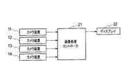
- FIG. 1 is a block diagram showing a configuration of a parking assistance apparatus shown as an embodiment of the present invention.
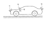
- FIG. 2 is a diagram showing an example of attachment of the camera device to the host vehicle in the parking assistance device shown as the embodiment of the present invention.
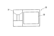
- FIG. 3 is a diagram showing a display example of the display in the parking assistance apparatus shown as the embodiment of the present invention.
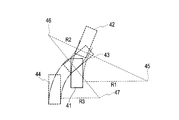
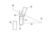
- FIG. 4 is a diagram illustrating an example of a parking locus calculated in the parking assistance device shown as the embodiment of the present invention when performing parallel parking toward the target parking position located on the left side of the host vehicle.
- FIG. 5 is a diagram showing a display example displayed on the display when the own vehicle located at the parking start position is moved forward and moved to the reverse start position.
- FIG. 1 is a block diagram showing a configuration of a parking assistance apparatus shown as an embodiment of the present invention.
- FIG. 2 is a diagram showing an example of attachment of the camera device to the host vehicle in the parking assistance device shown as the embodiment of the present invention.
- FIG. 6 is a diagram showing another display example displayed on the display when the host vehicle located at the parking start position is moved forward and moved to the reverse start position.
- FIG. 7 is a diagram illustrating a display example displayed on the display when the own vehicle located at the reverse start position is moved backward and moved to the parking position.
- FIG. 8 is a diagram illustrating a display example displayed on the display when the own vehicle located at the midway position of parking is moved backward to the target parking position.
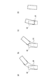
- FIG. 9 is a diagram showing a state of an ideal course prediction line that changes as the host vehicle moves in the state shown in FIG.
- the parking assist device shown as an embodiment of the present invention includes a plurality of in-vehicle camera devices 11, 12, 13, and 14 that capture images around the host vehicle, and these camera devices 11, 12, 13, and 14. 14 is provided with an image processing controller 21 that processes the video around the host vehicle imaged by 14 and a display 22 that displays the video processed by the image processing controller 21.
- the camera devices 11, 12, 13, and 14 are configured by using, for example, a CCD (Charge Coupled Devices) that can capture a small, high-quality image as an imaging element, and capture all the 360 ° range around the host vehicle.
- a plurality of such vehicles are provided in the host vehicle.
- one camera device 11, 12, 13, 14 is provided at each of four locations on the front side of the host vehicle, on the left and right sides of the host vehicle, and on the rear side of the host vehicle. The scenery of the front, the left and right sides, and the rear of the vehicle is captured.
- the camera devices 11, 12, 13, and 14 are actually very small in shape so that they do not protrude from the contour of the vehicle body of the vehicle and are installed in the vehicle or incorporated in the vehicle body or the like. Several are installed. Images captured by these camera devices 11, 12, 13, and 14 are supplied to the image processing controller 21 as electrical signals.
- the parking assist device may be provided with four or more camera devices as long as it can capture the entire 360 ° range around the host vehicle.
- the image processing controller 21 is based on video information captured by the plurality of camera devices 11, 12, 13, and 14, as if it were captured by a single virtual camera device mounted directly above the host vehicle. Generate a bird's-eye view image converted to a view point.
- the image processing controller 21 that realizes such a function is equipped with a DSP (Digital Signal Processor) that is a core of image processing and can be designed as an ASIC (Applicant Specific Integrated Circuit) that is an application specific integrated circuit or an FPGA (FPGA). (Field ⁇ ⁇ Programmable Gate Array). Since the image processing controller 21 cannot capture images of the own vehicle by the camera devices 11, 12, 13, and 14, the image processing controller 21 displays the image by superimposing CG (Computer Graphics) or a photograph on the generated overhead image.
- CG Computer Graphics
- the image processing controller 21 can also generate a bird's-eye view video obtained by enlarging a part of the generated bird's-eye view video. Further, when parking at a predetermined target parking position, the image processing controller 21 calculates a parking locus for guiding the host vehicle to the target parking position, and performs parking on the generated overhead image.
- a line, an ideal course prediction line (hereinafter referred to as an ideal course prediction line) that reaches the target parking position, and the like are superimposed and drawn.
- Such an image processing controller 21 displays the generated video on the display 22.
- the display 22 is composed of, for example, an in-vehicle liquid crystal display attached near the dashboard of the host vehicle.
- this display 22 can be shared with what displays map information etc., when navigating the own vehicle.
- the display 22 displays information including a bird's-eye view image supplied from the image processing controller 21 on the display screen, thereby presenting the driver with information for assisting parking at the target parking position.
- the in-vehicle display 22 usually has a horizontally long display screen, whereas the overhead view image generated by the image processing controller 21 represents the host vehicle moving in the front-rear direction. Often becomes vertically long. Therefore, for example, as shown in FIG.
- the display area of the display 22 is roughly divided into an overhead view video display area 31 that displays an overhead view video and a non-overhead view video display area 32 other than the overhead view video display area 31.
- the non-overhead video display area 32 an image captured by the camera device 11 in front of the host vehicle, an image captured by the camera device 14 behind the host vehicle, and the like are displayed. Accordingly, the display 22 can display an image that is easy for the driver to view and is necessary for parking.
- a configuration is considered in which an image captured by the camera device 11 in front of the host vehicle is displayed when the host vehicle is moving forward and is switched to a video image captured by the camera device 14 behind the host vehicle when the host vehicle is moving backward.
- these camera devices 11 and 14 since these camera devices 11 and 14 usually have the same mounting height and mounting angle with respect to the host vehicle, their images are often difficult to distinguish. Therefore, information for identifying which video is displayed may be displayed on the display 22.
- the parking assist device including such units superimposes and draws the reverse start position, the target parking position, the parking position, the steering interlock line, the ideal course prediction line, etc. Information that supports parking at the target parking position is presented to the driver.
- the process of a parking assistance apparatus is demonstrated taking the case of performing parallel parking as an example.
- the host vehicle is moved to a parking midway position 43 around a second rotation center 46 located at a distance of a radius R2 from the first rotation center 45.
- a certain amount of steering is rotated and steered, and the vehicle is located on the right side of the vehicle at the parking position 43 and is separated from the left edge of the target parking position 44 by a distance of radius R3.
- the host vehicle is moved to the target parking position 44 around the third rotation center 47 at the position. Thereby, the own vehicle can complete parallel parking.
- the stop position of the target to be moved next and the target rudder angle for reaching the target are displayed on the overhead view video, and the parking support is simply performed. Presents information that allows the driver to easily understand the route.
- FIG. 5 shows a state in which the steering is in a neutral state, and the steering interlocking line 52 extends linearly in front of the host vehicle.
- This linear steering interlocking line 52 indicates the steering of the steering wheel. Change with. That is, the image processing controller 21 calculates the steering interlock line 52 according to the steering of the steering. From the state shown in FIG. 5, when the driver steers the steering wheel in the right direction and moves forward with the steering interlocking line 52 overlapping the ideal course prediction line 51, the reverse start position is reached. It is possible to move appropriately toward 42.
- the parking support device in the first step, by displaying such information on the display 22, how much steering should be steered and which position is the reverse start position 42. Such information that assists parking can be clearly recognized by the driver.
- the target parking position 44 is a necessary frame line to make the driver imagine the entire parking route, but if it is always displayed simultaneously with other lines, it should move to the driver next. Sometimes it feels confusing with the borderline of the target stop position. Therefore, in the parking assistance device, under the control of the image processing controller 21, the frame line of the target parking position 44 is displayed on the display 22 when the host vehicle is stopped, while the target parking position 44 is displayed while the host vehicle is moving. The display line may be switched such that the frame line is not displayed on the display 22.
- the image processing controller 21 does not display the ideal predicted route 51 and the steering interlocking line 52 interlocked with the steering as shown in FIG. 5, but ideally reaches the reverse start position 42 as shown in FIG.
- These pieces of information are generated so that an ideal tire cutting angle line 61 indicating the cutting angle of the tire and a tire cutting angle interlocking line 62 indicating the tire cutting angle linked to steering are displayed on the overhead view video. You may do it.
- the length of the line to be displayed is shorter than that in the case shown in FIG. 5, and necessary information can be simply shown to the driver.
- FIG. 5 has been described on the assumption that the trajectory of the rear wheel of the host vehicle is changed, the image processing controller 21 displays a steering wheel cut-off by displaying the trajectory of the angle of the front end of the host vehicle or an icon such as an arrow. A corner may be expressed.
- the driver can be informed of information such as how much steering is required to reach the reverse start position 42 and how much steering is currently being performed, In addition, any information may be displayed on the display 22 as long as the display content allows the driver to grasp that the host vehicle moves forward.
- the image processing controller 21 has a frame line of a parking halfway position 43 that is a target stop position to be moved next (also referred to as a turning frame corresponding to the turning position). Then, such information is generated so that the ideal course prediction line 71 reaching the parking midway position 43 and the steering interlocking line 72 interlocked with the steering angle of the host vehicle are displayed on the overhead view video. At this time, the image processing controller 21 uses the marks different from the marks representing the ideal course prediction line 51 and the steering interlock line 52 shown in FIG. Such information is generated so that the line 71 and the steering interlocking line 72 are displayed on the overhead view video. In FIG.
- the steering interlock line 72 is displayed so as to draw an arc in the right direction.
- This arc-shaped steering interlock line 72 also changes as the steering operation is performed. That is, the image processing controller 21 calculates the steering interlock line 72 according to the steering of the steering. From the state shown in FIG. 7, the driver steers the steering to the left so that the steering interlock line 72 overlaps the ideal course prediction line 71, and the steering interlock line 72 and the ideal course prediction line 71 If the steering is fixed and the vehicle moves backward with the two wheels overlapped, the vehicle can be appropriately moved toward the parking position 43.
- the frame 22 of the target stop position to be moved next when the host vehicle moves forward, the steering interlocking line, and the ideal course prediction line are displayed using predetermined marks.
- the frame line of the target stop position to be moved next, the steering interlocking line, and the ideal course prediction line are displayed using marks different from those at the time of forward movement.
- the display can be configured simply, and information that allows the driver to easily recall the parking route up to the parking position 43 can be presented. Further, in the parking assistance device, it is possible to make the driver clearly understand the information for assisting parking, such as the distinction between forward and backward, and how much the steering is steered.
- the image processing controller 21 replaces the display of the ideal course prediction line 71 and the steering interlocking line 72 interlocked with the steering steering as shown in FIG. These pieces of information may be generated so that the tire turning angle line and the tire turning angle interlocking line are displayed on the bird's-eye view video.
- FIG. 7 has been described on the assumption that the trajectory of the rear wheel of the host vehicle changes, the image processing controller 21 displays the steering wheel by displaying the trajectory of the rear end of the host vehicle and an icon such as an arrow. You may make it express a cutting angle.
- the image processing controller 21 generates information so that the display content is substantially the same as the display content described with reference to FIG. That is, the image processing controller 21, for example, as shown in FIG. 8, the frame line of the target parking position 44 that is the target stop position to be moved next, the ideal course prediction line 81 that reaches this target parking position 44, Such information is generated so that the steering interlocking line 82 interlocked with the steering angle of the host vehicle is displayed on the bird's-eye view video.
- the image processing controller 21 uses the marks different from the marks representing the ideal course prediction line 51 and the steering interlock line 52 shown in FIG. Such information is generated so that the line 81 and the steering interlocking line 82 are displayed on the overhead view video.
- FIG. 8 the image processing controller 21 uses the marks different from the marks representing the ideal course prediction line 51 and the steering interlock line 52 shown in FIG.
- Such information is generated so that the line 81 and the steering interlocking line 82 are displayed on the overhead view video.
- the steering interlock line 82 is displayed so as to draw an arc in the left direction.
- This arc-shaped steering interlocking line 82 also changes as the steering is steered. That is, the image processing controller 21 calculates the steering interlock line 82 according to the steering of the steering.
- the driver steers the steering wheel to the right so that the steering interlock line 82 overlaps the ideal course prediction line 81 as shown in FIG.
- the interlocking line 82 and the ideal course prediction line 81 overlap with each other, as shown in FIG. 9 (b), when the steering is fixed and the vehicle moves backward, as shown in FIG. 9 (c), the direction toward the target parking position 44 is reached. Finally, as shown in FIG. 9D, the target parking position 44 is reached.
- the image processing controller 21 deletes the target parking position 44 when the mark indicating the position of the host vehicle and the target parking position 44 substantially overlap as shown in FIG. In this way, the target parking position 44 is deleted because there is a possibility that another vehicle is stopped before or after the target parking position 44, or there is a possibility that a white line is drawn on the actual ground. This is because the necessity of displaying the target parking position 44 is low.
- the parking assistance device in the case of the third step, such information is displayed on the display 22 so that the screen display can be simply configured and the parking up to the target parking position 44 is possible. It is possible to present information that the driver can easily recall. Further, in the parking assistance device, it is possible to make the driver clearly understand the information for assisting parking, such as the distinction between forward and backward, and how much the steering is steered.
- the image processing controller 21 replaces the display of the ideal course prediction line 81 and the steering interlocking line 82 interlocked with the steering as shown in FIG.
- Such information may be generated so that the ideal tire turning angle line and the tire turning angle interlocking line as shown are displayed on the bird's-eye view video.
- the image processing controller 21 can display the angle trajectory of the rear end of the host vehicle or an icon such as an arrow.
- the steering angle may be expressed.
- the parking assistance device at each stage of parking, the target stop position to be moved next, the steering interlocking line, and the ideal course prediction line are displayed on the bird's-eye view image, so that any line is displayed.
- the driver can easily grasp whether the steering should be steered or the own vehicle should be moved. Therefore, the parking assistance device provides an easy-to-see screen display while retaining an image of the entire parking route, and allows the driver to clearly and easily grasp the distinction between forward and reverse and the steering state of the steering wheel. Can do.
- not all lines are displayed on the display 22 at the same time, so that a great distortion occurs in the appearance of obstacles on the display 22 or parking of an ideal course prediction line, a steering interlock line, etc. It is possible to prevent the trace line, the frame line of the parking position, and the like from becoming very small and becoming difficult to visually recognize.
- the mark indicating the ideal course prediction line and the steering interlocking line displayed on the bird's-eye view image is different between when the vehicle is moving forward and when the vehicle is moving backward.
- the overhead view video displayed in the overhead view video display area 31 is fixed by the display and the video displayed in the non-overhead video display area 32 is taken by the camera device 11 in front of the host vehicle. Even if it is difficult to distinguish whether the image is captured by the camera device 14 behind the host vehicle, the driver can instantly determine whether the host vehicle is currently moving forward or backward. .
- the parking support apparatus performs parallel parking toward the target parking position positioned on the right side of the own vehicle.
- the present invention can be similarly applied to the case where the parking is performed, and can also be similarly applied to the case where parallel parking is performed toward the target parking position located on the left side or the right side of the host vehicle.
- the frame lines displayed on the bird's-eye view video are displayed for the reverse start position 42 and the parking middle position 43. It is desirable to display on the display 22 with a width wider than the vehicle width of the host vehicle, and to display the target parking position 44 on the display 22 with the same width as the vehicle width of the host vehicle.
- the reason why the reverse start position 42 and the parking midway position 43 are displayed on the display 22 with a width wider than the vehicle width of the host vehicle is to move the host vehicle to the target reverse start position 42 and parking midway position 43 to be moved next.
- the target parking position 44 is displayed on the display 22 with the same width as the vehicle width of the host vehicle.
- the target parking position 44 is also used when the parking position is set. It is difficult for the person to understand. The reason for this display is that when the host vehicle is moved to the reverse start position 42 and the parking midway position 43, the host vehicle is targeted at the frame line drawn on the actual ground or other surrounding vehicles. The vehicle must be displayed at the target parking position 44 while the frame indicating the reverse start position 42 and the parking intermediate position 43 must be displayed until the host vehicle is moved to that position.
- the display content may be changed according to the shift signal of the host vehicle and the vehicle speed V.
- the image processing controller 21 is linked to the frame line of the target stop position to be moved next and the steering operation.
- the image processing controller 21 sets the frame line of the target stop position to be moved next, the steering interlock line linked to the steering steering, and the tire running out.
- a parking locus line such as a corner interlocking line is displayed on the display 22 and, in addition to this information, a frame line of the target parking position, an ideal course prediction line, and an ideal tire cutting angle line And the like are displayed on the display 22.
- the frame line of the target parking position 44 is displayed on the display 22 so that the driver can know which stage of the parking route the vehicle is currently in. It can be made easy to grasp.
- the image processing controller 21 displays the frame line of the target parking position 44 on the display 22 for a predetermined time. It is desirable to erase afterwards. Thereby, in the parking assistance device, it is possible to prevent the driver from being confused due to the frame line of the target parking position 44 disappearing from the display 22 immediately after the start of movement of the host vehicle.
- the length of the steering interlock line is shortened on the display 22 under the control of the image processing controller 21 as the host vehicle approaches the target stop position to be moved next. You may make it display. Thereby, in the parking assistance device, the distance from the target stop position to be moved next can be measured, and a complicated feeling is given to the driver by simplifying the display of the displayed steering interlocking line. Can be prevented.
- the fact that the host vehicle is approaching the target stop position or the target parking position 44 to which the host vehicle should move next is not sound or video. It is desirable to notify the driver by means. Thereby, in the parking assistance device, even when the driver himself / herself visually confirms the surrounding situation, the driver can determine which stage of the parking route the vehicle is currently in.
- images captured by the plurality of camera apparatuses 11, 12, 13, and 14 are controlled under the control of the image processing controller 21.
- the image processing controller 21 Based on the parking locus for guiding the host vehicle to the target parking position 44 on the generated bird's-eye view image by generating a bird's-eye view image converted from the image captured from directly above the host vehicle based on each stage of parking Every time, the target stop position to which the host vehicle should move next and the parking locus line to the stop position are displayed on the display 22.
- the surroundings of the own vehicle are image
- photographed image is connected, From the upper direction of the own vehicle. Since a bird's-eye view image is generated, and the generated bird's-eye view image and a turning frame corresponding to the turning position for steering turning while the vehicle is moving backward to the target parking position 44 are displayed on the display 22. The driver can easily carry out the reverse to the parking position.
- this parking assist apparatus under the control of the image processing controller 21, as a parking locus line, a steering interlock line that is a line interlocked with steering steering, and a target stop position where the host vehicle should move next.
- a steering interlock line that is a line interlocked with steering steering
- a target stop position where the host vehicle should move next.
- the vehicle trajectory moves along with the tire turning angle interlocking line indicating the turning angle of the tire interlocked with the steering steering as the parking locus line.
- the length of the line displayed on the display 22 can be shortened, and the necessary information can be simplified.
- the driver can clearly grasp the target stop position and the steering amount of the steering to be moved next, and the parking action can be facilitated.
- this parking assist device when the shift signal of the host vehicle is other than reverse and the vehicle speed V is V> 0 under the control of the image processing controller 21, the host vehicle moves next.
- the target parking position 44 is set. By displaying the display 22 for a predetermined time and then deleting it, it is possible to prevent the driver from being confused due to the frame line of the target parking position 44 disappearing from the display 22 immediately after the start of movement of the host vehicle. .
- the target stop position where the host vehicle should move next is displayed on the display 22 with a width wider than the width of the host vehicle.
- the target parking position 44 is set.
- the target parking position 44 displayed on the display 22 is deleted, so that the positional relationship between the host vehicle and the frame line drawn on the actual ground and the surrounding other vehicle can be determined. This makes it possible for the driver to clearly grasp the parking action.
- this parking assist device under the control of the image processing controller 21, as the host vehicle approaches the target stop position to which the host vehicle should move next, steering control is performed on the parking locus line.
- the steering interlocking line which is an interlocking line
- displaying it on the display 22 it is possible to measure the distance from the target stop position to be moved next, and to display the displayed steering interlocking line. It is possible to prevent the driver from having a complicated feeling.
- this parking assistance device under the control of the image processing controller 21, a sound or video indicating that the host vehicle is approaching the target stop position or target parking position 44 to which the host vehicle should move next.
- the mark representing the parking locus line is displayed on the display 22 differently when the host vehicle is moving forward and backward. The driver can clearly and easily understand the distinction from reverse.
- the overhead view image is generated by converting the viewpoint to the image captured directly above the host vehicle, and the overhead view is generated.
- the target stop position to which the host vehicle should move next and the parking trajectory line to the stop position are shown for each stage of parking. displayed.
- the steering frame corresponding to the steered position to steer while the host vehicle is moving backward to the target parking position is displayed on the bird's-eye view image, so that the driver can easily move backward to the parking halfway position. Can be implemented. Therefore, the parking assistance device and the driving assistance method of the present invention can be used industrially.
Landscapes
- Engineering & Computer Science (AREA)
- Mechanical Engineering (AREA)
- Multimedia (AREA)
- Physics & Mathematics (AREA)
- General Physics & Mathematics (AREA)
- Theoretical Computer Science (AREA)
- Transportation (AREA)
- Combustion & Propulsion (AREA)
- Chemical & Material Sciences (AREA)
- Closed-Circuit Television Systems (AREA)
- Fittings On The Vehicle Exterior For Carrying Loads, And Devices For Holding Or Mounting Articles (AREA)
- Traffic Control Systems (AREA)
- Image Processing (AREA)
- Image Analysis (AREA)
- Steering Control In Accordance With Driving Conditions (AREA)
Abstract
Description
本発明の実施形態として示す駐車支援装置は、図1に示すように、自車両周囲の映像を撮像する複数の車載カメラ装置11,12,13,14と、これらカメラ装置11,12,13,14によって撮像された自車両周囲の映像を処理する画像処理コントローラ21と、この画像処理コントローラ21によって処理された映像を表示するディスプレイ22とを備える。 [Configuration of parking assist device]
As shown in FIG. 1, the parking assist device shown as an embodiment of the present invention includes a plurality of in-
このような各部を備える駐車支援装置は、生成した俯瞰映像上に、駐車を行う際の後退開始位置、目標駐車位置、駐車途中位置、操舵連動線、及び理想進路予想線等を重畳描画し、目標駐車位置に対する駐車を支援する情報を運転者に提示する。以下、縦列駐車を行う場合を例にとり、駐車支援装置の処理について説明する。 [Operation of parking assist device]
The parking assist device including such units superimposes and draws the reverse start position, the target parking position, the parking position, the steering interlock line, the ideal course prediction line, etc. Information that supports parking at the target parking position is presented to the driver. Hereinafter, the process of a parking assistance apparatus is demonstrated taking the case of performing parallel parking as an example.
まず、上述した第1のステップとして駐車開始位置41に位置する自車両を前進させて後退開始位置42に移動させる際に、ディスプレイ22に表示する線について説明する。 [Display contents in the first step]
First, a line displayed on the
つぎに、上述した第2のステップとして後退開始位置42に位置する自車両を後退させて駐車途中位置43に移動させる際に、ディスプレイ22に表示する線について説明する。 [Display contents in the second step]
Next, lines displayed on the
最後に、上述した第3のステップとして駐車途中位置43に位置する自車両を後退させて目標駐車位置44に移動させる際に、ディスプレイ22に表示する線について説明する。 [Display contents in the third step]
Finally, a line displayed on the
Claims (21)
- 自車両周囲を撮影する複数の車載カメラと、
前記複数の車載カメラで撮影された複数の映像を繋ぎ合わせるとともに前記自車両の上方から見下ろした俯瞰映像を生成する俯瞰映像生成手段と、
前記生成された俯瞰映像と、前記自車両が所定の目標駐車位置へ後退する途中でステアリング転舵を行うための転舵位置に対応した転舵枠とを表示する表示手段と、
を備えることを特徴とする車両用駐車支援装置。 A plurality of in-vehicle cameras that capture the area around the vehicle,
Overhead video generation means for connecting a plurality of videos taken by the plurality of vehicle-mounted cameras and generating an overhead video viewed from above the host vehicle;
Display means for displaying the generated bird's-eye view image and a turning frame corresponding to a turning position for performing steering turning while the host vehicle is moving backward to a predetermined target parking position;
A parking assist device for a vehicle, comprising: - 前記駐車支援装置は、前記表示手段に、前記生成された俯瞰映像上に前記転舵枠と前記転舵位置までの駐車軌跡線とを表示させる画像処理制御手段を更に備え、
前記画像処理制御手段は、前記駐車軌跡線として、ステアリング操舵に連動した線である操舵連動線と、次に前記自車両が移動すべき前記転舵位置に至る理想的な進路予想線である理想進路予想線とを前記表示手段に表示させることを特徴とする請求項1記載の駐車支援装置。 The parking assist device further includes image processing control means for causing the display means to display the turning frame and a parking locus line to the turning position on the generated overhead view image,
The image processing control means is an ideal as a parking locus line that is a steering interlock line that is a line interlocked with steering and an ideal course prediction line that leads to the steered position where the host vehicle should move next. The parking assistance apparatus according to claim 1, wherein a predicted route is displayed on the display means. - 前記駐車支援装置は、前記表示手段に、前記生成された俯瞰映像上に前記転舵枠と前記転舵位置までの駐車軌跡線とを表示させる画像処理制御手段を更に備え、
前記画像処理制御手段は、前記駐車軌跡線として、ステアリング操舵に連動したタイヤの切れ角を示すタイヤ切れ角連動線と、次に前記自車両が移動すべき前記転舵位置に至る理想的なタイヤの切れ角を示す理想タイヤ切れ角線とを前記表示手段に表示させることを特徴とする請求項1記載の駐車支援装置。 The parking assist device further includes image processing control means for causing the display means to display the turning frame and a parking locus line to the turning position on the generated overhead view image,
The image processing control means includes a tire turning angle interlocking line indicating a turning angle of a tire interlocked with steering steering as the parking locus line, and an ideal tire that reaches the steered position where the host vehicle should move next. The parking assist device according to claim 1, wherein an ideal tire turning angle line indicating a turning angle is displayed on the display means. - 前記駐車支援装置は、前記表示手段に、前記生成された俯瞰映像上に前記転舵枠と前記転舵位置までの駐車軌跡線とを表示させる画像処理制御手段を更に備え、
前記画像処理制御手段は、
前記自車両のシフト信号がリバース以外であり、車速VがV>0の場合には、次に前記自車両が移動すべき前記転舵位置の前記転舵枠と、ステアリング操舵に連動した駐車軌跡線とを前記表示手段に表示させ、車速VがV=0の場合には、次に前記自車両が移動すべき前記転舵位置の前記転舵枠と、ステアリング操舵に連動した駐車軌跡線と、前記目標駐車位置とを前記表示手段に表示させ、
前記自車両のシフト信号がリバースであり、車速VがV>0の場合には、次に前記自車両が移動すべき前記転舵位置の前記転舵枠と、ステアリング操舵に連動した駐車軌跡線とを前記表示手段に表示させ、車速VがV=0の場合には、次に前記自車両が移動すべき前記転舵位置の前記転舵枠と、操舵指示の駐車軌跡線と、前記目標駐車位置とを前記表示手段に表示させること
を特徴とする請求項1乃至請求項3のうちいずれか1項記載の駐車支援装置。 The parking assist device further includes image processing control means for causing the display means to display the turning frame and a parking locus line to the turning position on the generated overhead view image,
The image processing control means includes
When the shift signal of the host vehicle is other than reverse and the vehicle speed V is V> 0, the steered frame at the steered position to which the host vehicle should move next and the parking locus linked to steering steering When the vehicle speed V is V = 0, the steering frame at the steered position to which the host vehicle should move next, and the parking locus line linked to steering steering , Display the target parking position on the display means,
When the shift signal of the host vehicle is reverse and the vehicle speed V is V> 0, the steered frame at the steered position to which the host vehicle should move next and the parking locus line linked to steering steering Is displayed on the display means, and when the vehicle speed V is V = 0, the steered frame of the steered position to which the host vehicle should move, the parking locus line of the steering instruction, and the target The parking support apparatus according to any one of claims 1 to 3, wherein a parking position is displayed on the display means. - 前記画像処理制御手段は、車速VがV=0からV>0に遷移して前記自車両が移動を開始した場合には、前記目標駐車位置を前記表示手段に所定時間だけ表示させた後、消去することを特徴とする請求項4記載の駐車支援装置。 When the vehicle speed V changes from V = 0 to V> 0 and the host vehicle starts moving, the image processing control means displays the target parking position on the display means for a predetermined time, The parking assist device according to claim 4, wherein the parking assist device is erased.
- 前記駐車支援装置は、前記表示手段に、前記生成された俯瞰映像上に前記転舵枠と前記転舵位置までの駐車軌跡線とを表示させる画像処理制御手段を更に備え、
前記画像処理制御手段は、次に前記自車両が移動すべき前記転舵位置の前記転舵枠を、当該自車両の車幅よりも広い幅で前記表示手段に表示させ、前記目標駐車位置を、当該自車両の車幅と同幅で前記表示手段に表示させることを特徴とする請求項1乃至請求項5のうちいずれか1項記載の駐車支援装置。 The parking assist device further includes image processing control means for causing the display means to display the turning frame and a parking locus line to the turning position on the generated overhead view image,
The image processing control means causes the display means to display the steered frame at the steered position to which the host vehicle should move next on a width wider than the vehicle width of the host vehicle, and sets the target parking position. The parking support device according to any one of claims 1 to 5, wherein the display means displays the same width as the vehicle width of the host vehicle. - 前記駐車支援装置は、前記表示手段に、前記生成された俯瞰映像上に前記転舵枠と前記転舵位置までの駐車軌跡線とを表示させる画像処理制御手段を更に備え、
前記画像処理制御手段は、次に前記自車両が移動すべき前記転舵位置に当該自車両が近付くにしたがって、前記駐車軌跡線のうち、ステアリング操舵に連動した線である操舵連動線の長さを短くして前記表示手段に表示させることを特徴とする請求項1乃至請求項6のうちいずれか1項記載の駐車支援装置。 The parking assist device further includes image processing control means for causing the display means to display the turning frame and a parking locus line to the turning position on the generated overhead view image,
The image processing control means is configured to determine a length of a steering interlock line that is a line interlocked with steering steering among the parking locus lines as the host vehicle approaches the steered position where the host vehicle should move next. The parking assist device according to any one of claims 1 to 6, wherein the display means displays the information by shortening the length. - 前記駐車支援装置は、前記表示手段に、前記生成された俯瞰映像上に前記転舵枠と前記転舵位置までの駐車軌跡線とを表示させる画像処理制御手段を更に備え、
前記画像処理制御手段は、次に前記自車両が移動すべき前記転舵位置又は前記目標駐車位置に当該自車両が近付いている旨を音又は映像以外の手段によって運転者に報知させることを特徴とする請求項1乃至請求項7のうちいずれか1項記載の駐車支援装置。 The parking assist device further includes image processing control means for causing the display means to display the turning frame and a parking locus line to the turning position on the generated overhead view image,
The image processing control means causes the driver to be notified by means other than sound or video that the own vehicle is approaching the steered position or the target parking position where the own vehicle should move next. The parking support apparatus according to any one of claims 1 to 7. - 前記駐車支援装置は、前記表示手段に、前記生成された俯瞰映像上に前記転舵枠と前記転舵位置までの駐車軌跡線とを表示させる画像処理制御手段を更に備え、
前記画像処理制御手段は、前記駐車軌跡線を表現するマークを、前記自車両の前進時と後退時とで異なるように前記表示手段に表示させることを特徴とする請求項1乃至請求項8のうちいずれか1項に記載の駐車支援装置。 The parking assist device further includes image processing control means for causing the display means to display the turning frame and a parking locus line to the turning position on the generated overhead view image,
9. The image processing control unit according to claim 1, wherein the display unit displays a mark representing the parking locus line so that the mark differs between when the host vehicle moves forward and when the host vehicle moves backward. The parking assistance apparatus of any one of them. - 自車両周囲を複数の車載カメラで撮影する撮影工程と、
撮影された複数の映像を繋ぎ合わせるとともに前記自車両の上方から見下ろした俯瞰映像を生成する俯瞰映像生成工程と、
生成された俯瞰映像と、前記自車両が所定の目標駐車位置へ後退する途中でステアリング転舵を行うための転舵位置に対応した転舵枠とを表示手段に表示する表示工程と、
を備えることを特徴とする車両用駐車支援方法。 A shooting process for shooting around the vehicle with a plurality of in-vehicle cameras,
An overhead image generation step of connecting a plurality of captured images and generating an overhead image looking down from above the host vehicle;
A display step of displaying on the display means the generated bird's-eye view image and a turning frame corresponding to a turning position for steering turning while the host vehicle is moving backward to a predetermined target parking position;
A vehicle parking assistance method comprising: - 自車両を所定の目標駐車位置に駐車させるために運転者に操作の支援となる情報を提示する駐車支援装置において、
前記自車両周囲の映像を撮像する複数の撮像手段と、
前記複数の撮像手段によって撮像された映像に基づいて、前記自車両の真上から撮像した映像に視点変換した俯瞰映像を生成し、生成した前記俯瞰映像上に、前記目標駐車位置に自車両を誘導するための駐車軌跡のうち、駐車の各段階毎に、次に前記自車両が移動すべき目標の停車位置と、当該停車位置までの駐車軌跡線とを所定の表示手段に表示させる画像処理制御手段と
を備えることを特徴とする駐車支援装置。 In the parking assistance device that presents information to assist the operation to the driver to park the host vehicle at a predetermined target parking position,
A plurality of imaging means for capturing images of the surroundings of the host vehicle;
Based on the images picked up by the plurality of image pickup means, a bird's-eye view image is generated by converting the viewpoint to a image picked up from directly above the host vehicle, and the host vehicle is placed at the target parking position on the generated bird's-eye view image. Image processing for displaying, on a predetermined display means, a target stop position to which the host vehicle should move next and a parking locus line to the stop position for each stage of parking among the parking locus for guidance. A parking support apparatus comprising: a control means. - 前記画像処理制御手段は、前記駐車軌跡線として、ステアリング操舵に連動した線である操舵連動線と、次に前記自車両が移動すべき目標の停車位置に至る理想的な進路予想線である理想進路予想線とを前記表示手段に表示させることを特徴とする請求項1記載の駐車支援装置。 The image processing control means is an ideal as a parking locus line that is a steering interlock line that is a line interlocked with steering and an ideal course prediction line that leads to a target stop position where the host vehicle should move next. The parking assistance apparatus according to claim 1, wherein a predicted route is displayed on the display means.
- 前記画像処理制御手段は、前記駐車軌跡線として、ステアリング操舵に連動したタイヤの切れ角を示すタイヤ切れ角連動線と、次に前記自車両が移動すべき目標の停車位置に至る理想的なタイヤの切れ角を示す理想タイヤ切れ角線とを前記表示手段に表示させることを特徴とする請求項1記載の駐車支援装置。 The image processing control means includes, as the parking locus line, a tire turning angle interlocking line indicating a tire turning angle interlocked with steering steering, and an ideal tire that reaches the target stop position where the host vehicle should move next. The parking assist device according to claim 1, wherein an ideal tire turning angle line indicating a turning angle is displayed on the display means.
- 前記画像処理制御手段は、
前記自車両のシフト信号がリバース以外であり、車速VがV>0の場合には、次に前記自車両が移動すべき目標の停車位置と、ステアリング操舵に連動した駐車軌跡線とを前記表示手段に表示させ、車速VがV=0の場合には、次に前記自車両が移動すべき目標の停車位置と、ステアリング操舵に連動した駐車軌跡線と、前記目標駐車位置とを前記表示手段に表示させ、
前記自車両のシフト信号がリバースであり、車速VがV>0の場合には、次に前記自車両が移動すべき目標の停車位置と、ステアリング操舵に連動した駐車軌跡線とを前記表示手段に表示させ、車速VがV=0の場合には、次に前記自車両が移動すべき目標の停車位置と、操舵指示の駐車軌跡線と、前記目標駐車位置とを前記表示手段に表示させること
を特徴とする請求項1乃至請求項3のうちいずれか1項記載の駐車支援装置。 The image processing control means includes
When the shift signal of the host vehicle is other than reverse and the vehicle speed V is V> 0, the target stop position where the host vehicle should move next and the parking locus line linked to steering steering are displayed. When the vehicle speed V is V = 0, the target stop position to which the host vehicle should move, the parking locus line linked to steering steering, and the target parking position are displayed. Displayed on the
When the shift signal of the host vehicle is reverse and the vehicle speed V is V> 0, a target stop position where the host vehicle should move next and a parking locus line linked to steering steering are displayed on the display means. When the vehicle speed V is V = 0, the display unit displays the target stop position to which the host vehicle should move next, the parking locus line of the steering instruction, and the target parking position. The parking assist device according to any one of claims 1 to 3, wherein the parking assist device is any one of claims 1 to 3. - 前記画像処理制御手段は、車速VがV=0からV>0に遷移して前記自車両が移動を開始した場合には、前記目標駐車位置を前記表示手段に所定時間だけ表示させた後、消去することを特徴とする請求項4記載の駐車支援装置。 When the vehicle speed V changes from V = 0 to V> 0 and the host vehicle starts moving, the image processing control means displays the target parking position on the display means for a predetermined time, The parking assist device according to claim 4, wherein the parking assist device is erased.
- 前記画像処理制御手段は、次に前記自車両が移動すべき目標の停車位置を、当該自車両の車幅よりも広い幅で前記表示手段に表示させ、前記目標駐車位置を、当該自車両の車幅と同幅で前記表示手段に表示させることを特徴とする請求項1乃至請求項5のうちいずれか1項記載の駐車支援装置。 The image processing control means causes the display means to display a target stop position to which the host vehicle should move next on a width wider than the vehicle width of the host vehicle, and displays the target parking position of the host vehicle. The parking assist device according to any one of claims 1 to 5, wherein the display means displays the same width as a vehicle width.
- 前記画像処理制御手段は、次に前記自車両が移動すべき目標の停車位置が前記目標駐車位置である場合には、当該目標駐車位置に前記自車両が近付いたときに、前記表示手段に表示されている当該目標駐車位置を消去することを特徴とする請求項1乃至請求項6のうちいずれか1項記載の駐車支援装置。 The image processing control means displays on the display means when the host vehicle approaches the target parking position when the target stop position where the host vehicle should move next is the target parking position. The parking assist device according to any one of claims 1 to 6, wherein the target parking position being deleted is erased.
- 前記画像処理制御手段は、次に前記自車両が移動すべき目標の停車位置に当該自車両が近付くにしたがって、前記駐車軌跡線のうち、ステアリング操舵に連動した線である操舵連動線の長さを短くして前記表示手段に表示させることを特徴とする請求項1乃至請求項7のうちいずれか1項記載の駐車支援装置。 The image processing control means determines a length of a steering interlock line that is a line interlocked with steering steering among the parking locus lines as the host vehicle approaches a target stop position where the host vehicle should move next. The parking support device according to claim 1, wherein the display means displays the information by shortening the length.
- 前記画像処理制御手段は、次に前記自車両が移動すべき目標の停車位置又は前記目標駐車位置に当該自車両が近付いている旨を音又は映像以外の手段によって運転者に報知させることを特徴とする請求項1乃至請求項7のうちいずれか1項記載の駐車支援装置。 The image processing control means causes the driver to be notified by means other than sound or video that the own vehicle is approaching the target stop position or the target parking position to which the own vehicle should move next. The parking support apparatus according to any one of claims 1 to 7.
- 前記画像処理制御手段は、前記駐車軌跡線を表現するマークを、前記自車両の前進時と後退時とで異なるように前記表示手段に表示させることを特徴とする請求項1乃至請求項9のうちいずれか1項に記載の駐車支援装置。 The image processing control means causes the display means to display a mark representing the parking locus line so that the mark differs when the host vehicle moves forward and backward. The parking assistance apparatus of any one of them.
- 自車両を所定の目標駐車位置に駐車させるために運転者に操作の支援となる情報を提示する駐車支援方法において、
前記自車両周囲の映像を撮像する複数の撮像手段によって撮像された映像に基づいて、前記自車両の真上から撮像した映像に視点変換した俯瞰映像を生成する俯瞰映像生成工程と、
前記俯瞰映像生成工程にて生成された前記俯瞰映像上に、前記目標駐車位置に自車両を誘導するための駐車軌跡のうち、駐車の各段階毎に、次に前記自車両が移動すべき目標の停車位置と、当該停車位置までの駐車軌跡線とを所定の表示手段に表示させる表示工程と
を有することを特徴とする駐車支援方法。 In the parking support method for presenting information to assist the operation to the driver in order to park the host vehicle at a predetermined target parking position,
An overhead view video generation step of generating an overhead view image converted from a viewpoint to a video imaged from directly above the own vehicle, based on images captured by a plurality of imaging means for capturing images around the host vehicle;
Of the parking locus for guiding the host vehicle to the target parking position on the overhead view image generated in the overhead view image generation step, the target to which the host vehicle should move next for each stage of parking And a display step of displaying on a predetermined display means a parking locus line up to the stopping position.
Priority Applications (5)
| Application Number | Priority Date | Filing Date | Title |
|---|---|---|---|
| EP09762483.7A EP2301812B1 (en) | 2008-06-10 | 2009-06-09 | Parking assist apparatus and parking assist method |
| US12/997,052 US8803707B2 (en) | 2008-06-10 | 2009-06-09 | Parking assistance system and parking assistance method |
| KR1020137025977A KR101375944B1 (en) | 2008-06-10 | 2009-06-09 | Parking assistance system |
| CN2009801215898A CN102056772B (en) | 2008-06-10 | 2009-06-09 | Parking assist apparatus and parking assist method |
| KR1020117000302A KR101362496B1 (en) | 2008-06-10 | 2009-06-09 | Parking assistance system and parking assistance method |
Applications Claiming Priority (2)
| Application Number | Priority Date | Filing Date | Title |
|---|---|---|---|
| JP2008151473A JP4900326B2 (en) | 2008-06-10 | 2008-06-10 | Parking assistance device and parking assistance method |
| JP2008-151473 | 2008-06-10 |
Publications (1)
| Publication Number | Publication Date |
|---|---|
| WO2009151053A1 true WO2009151053A1 (en) | 2009-12-17 |
Family
ID=41416760
Family Applications (1)
| Application Number | Title | Priority Date | Filing Date |
|---|---|---|---|
| PCT/JP2009/060537 WO2009151053A1 (en) | 2008-06-10 | 2009-06-09 | Parking assist apparatus and parking assist method |
Country Status (6)
| Country | Link |
|---|---|
| US (1) | US8803707B2 (en) |
| EP (1) | EP2301812B1 (en) |
| JP (1) | JP4900326B2 (en) |
| KR (2) | KR101362496B1 (en) |
| CN (2) | CN102056772B (en) |
| WO (1) | WO2009151053A1 (en) |
Cited By (6)
| Publication number | Priority date | Publication date | Assignee | Title |
|---|---|---|---|---|
| WO2013024523A1 (en) * | 2011-08-12 | 2013-02-21 | トヨタ自動車株式会社 | Parking assistance device |
| KR101269183B1 (en) | 2012-09-14 | 2013-06-05 | 주식회사 세코닉스 | Bird view image control method for navigator |
| CN103609100A (en) * | 2011-06-09 | 2014-02-26 | 爱信精机株式会社 | Image generation device |
| WO2014065485A1 (en) | 2012-10-24 | 2014-05-01 | (주)세코닉스 | Device and method for producing bird's eye view having function of automatically correcting image |
| KR101693820B1 (en) | 2016-01-13 | 2017-01-06 | 광운대학교 산학협력단 | Calibration apparatus and method for around view monitoring image |
| CN109138561A (en) * | 2017-06-16 | 2019-01-04 | 纵目科技(上海)股份有限公司 | The method and system of virtual parking stall automatic parking is set |
Families Citing this family (53)
| Publication number | Priority date | Publication date | Assignee | Title |
|---|---|---|---|---|
| CN1132750C (en) * | 1998-10-08 | 2003-12-31 | 松下电器产业株式会社 | Driving assisting device and recording medium |
| JP4900232B2 (en) * | 2007-12-26 | 2012-03-21 | 日産自動車株式会社 | Vehicle parking assist device and video display method |
| JP4661917B2 (en) * | 2008-07-25 | 2011-03-30 | 日産自動車株式会社 | Parking assistance device and parking assistance method |
| CN102933429B (en) * | 2010-06-09 | 2015-04-29 | 日产自动车株式会社 | Parking mode selection device and method |
| US8890716B2 (en) * | 2010-06-11 | 2014-11-18 | Nissan Motor Co., Ltd. | Parking assist apparatus and method |
| WO2012017560A1 (en) | 2010-08-06 | 2012-02-09 | 富士通株式会社 | Image processing device and image processing program |
| JP2012119755A (en) | 2010-11-29 | 2012-06-21 | Panasonic Corp | Drive support display device |
| JP5519479B2 (en) * | 2010-11-29 | 2014-06-11 | パナソニック株式会社 | Driving support display device |
| JP5998496B2 (en) * | 2011-02-02 | 2016-09-28 | 日産自動車株式会社 | Parking assistance device |
| US8290657B2 (en) * | 2011-04-06 | 2012-10-16 | Ford Global Technologies | Direction determination for active park assist |
| KR101803973B1 (en) * | 2011-05-09 | 2017-12-01 | 엘지이노텍 주식회사 | Parking camera system and method of driving the same |
| CN102774380A (en) * | 2011-05-12 | 2012-11-14 | 无锡维森智能传感技术有限公司 | Method for judging running state of vehicle |
| JP2012244600A (en) * | 2011-05-24 | 2012-12-10 | Fujitsu Ten Ltd | Image display system, image processing apparatus, and image display method |
| WO2012172923A1 (en) * | 2011-06-16 | 2012-12-20 | アイシン精機株式会社 | Vehicle periphery monitoring device |
| JP5668857B2 (en) | 2011-07-29 | 2015-02-12 | 富士通株式会社 | Image processing apparatus, image processing method, and image processing program |
| KR101829007B1 (en) * | 2011-11-14 | 2018-02-14 | 현대모비스 주식회사 | Method of back parking assist |
| US9697735B2 (en) | 2011-12-15 | 2017-07-04 | Panasonic Intellectual Property Management Co., Ltd. | Drive assistance device |
| KR101327736B1 (en) * | 2011-12-23 | 2013-11-11 | 현대자동차주식회사 | AVM Top View Based Parking Support System |
| US9598836B2 (en) | 2012-03-29 | 2017-03-21 | Harnischfeger Technologies, Inc. | Overhead view system for a shovel |
| KR101877570B1 (en) * | 2012-04-04 | 2018-07-11 | 현대자동차주식회사 | Apparatus for setting parking position based on around view image and method thereof |
| CN102745198B (en) * | 2012-07-23 | 2014-12-03 | 北京智华驭新汽车电子技术开发有限公司 | Auxiliary forward track device for vehicle |
| WO2014020727A1 (en) | 2012-08-01 | 2014-02-06 | トヨタ自動車株式会社 | Drive assist device |
| KR101366112B1 (en) * | 2012-09-04 | 2014-02-24 | 전자부품연구원 | Avm system of vehicle for dividing and managing camera networks and avm method thereof |
| WO2014108987A1 (en) | 2013-01-11 | 2014-07-17 | 日産自動車株式会社 | Display control device for vehicle and display control method for vehicle |
| US9683861B2 (en) * | 2013-09-27 | 2017-06-20 | Nissan Motor Co., Ltd. | Estimated route presentation apparatus and estimated route presentation method |
| CN106183992B (en) * | 2013-10-04 | 2019-03-15 | 本田技研工业株式会社 | Parking aid |
| JP5844329B2 (en) * | 2013-10-04 | 2016-01-13 | 本田技研工業株式会社 | Parking assistance device |
| KR102135900B1 (en) * | 2013-11-29 | 2020-08-26 | 현대모비스(주) | Apparatus and Method for Assisting Parking |
| DE102014200661A1 (en) * | 2014-01-16 | 2015-07-16 | Ford Global Technologies, Llc | Detection of a parking operation of a motor vehicle |
| US9981605B2 (en) * | 2014-05-16 | 2018-05-29 | GM Global Technology Operations LLC | Surround-view camera system (VPM) and vehicle dynamic |
| JP6096155B2 (en) * | 2014-09-12 | 2017-03-15 | アイシン精機株式会社 | Driving support device and driving support system |
| JP6580872B2 (en) * | 2015-06-05 | 2019-09-25 | 株式会社デンソーテン | Driving support device and driving support method |
| KR101795151B1 (en) * | 2015-10-05 | 2017-12-01 | 현대자동차주식회사 | Parking guidance apparatus and method for vehicle |
| CN106864369A (en) * | 2015-12-11 | 2017-06-20 | 华创车电技术中心股份有限公司 | Parking auxiliary ring field image system |
| KR102005944B1 (en) * | 2016-10-19 | 2019-08-01 | 주식회사 만도 | Parking Assist System and Method thereof |
| DE102017200216A1 (en) * | 2017-01-09 | 2018-07-12 | Bayerische Motoren Werke Aktiengesellschaft | Control unit and method for providing a correction train for a reversing assistance system |
| EP3550829B1 (en) * | 2017-04-03 | 2021-08-11 | Jvc Kenwood Corporation | Bird's-eye-view video generation device, bird's-eye-view video display device, bird's-eye-view video generation method, and program |
| JP6873800B2 (en) * | 2017-04-13 | 2021-05-19 | 三菱ロジスネクスト株式会社 | Work vehicle steering display and work vehicle |
| KR20180136134A (en) * | 2017-06-14 | 2018-12-24 | 주식회사 만도 | Smart parking assist system and method for driving thereof |
| CN107719234A (en) * | 2017-09-22 | 2018-02-23 | 郭金林 | A kind of dynamic reverse track video system and its application |
| JP2019060616A (en) * | 2017-09-25 | 2019-04-18 | アイシン精機株式会社 | Driving assistance device |
| US11193784B2 (en) * | 2017-10-13 | 2021-12-07 | Waymo Llc | End of trip sequence |
| JP6917330B2 (en) * | 2018-03-28 | 2021-08-11 | 日立Astemo株式会社 | Parking support device |
| FR3084044A1 (en) * | 2018-07-17 | 2020-01-24 | Psa Automobiles Sa | METHOD AND DEVICE FOR ASSISTING THE DRIVING OF A VEHICLE, BY CONTEXTUAL DISPLAY OF FRONT PANORAMIC IMAGES. |
| CN108791279B (en) * | 2018-07-27 | 2021-10-15 | 江西江铃集团新能源汽车有限公司 | Semi-automatic parking system, automobile and parking method |
| US11507087B2 (en) * | 2018-11-07 | 2022-11-22 | Gm Cruise Holdings Llc | Distributed integrated sensing and communication module |
| CN109816588B (en) * | 2018-12-29 | 2023-03-21 | 百度在线网络技术(北京)有限公司 | Method, device and equipment for recording driving trajectory |
| DE112020000391T5 (en) | 2019-01-10 | 2021-10-07 | Jaguar Land Rover Limited | A control system, system and method for assisting a vehicle occupant |
| KR20200132468A (en) * | 2019-05-17 | 2020-11-25 | 삼성전자주식회사 | Advanced driver assist device and method of detecting object in the same |
| US20220219678A1 (en) * | 2020-02-10 | 2022-07-14 | Nissan Motor Co., Ltd. | Parking Assist Method and Parking Assist Apparatus |
| CN113282073B (en) * | 2021-05-24 | 2022-06-17 | 安徽江淮汽车集团股份有限公司 | Vehicle driving track simulation method, vehicle and computer readable storage medium |
| EP4141472A1 (en) * | 2021-08-30 | 2023-03-01 | GM Cruise Holdings LLC | Computing architecture of an autonomous vehicle |
| TWI832598B (en) * | 2022-12-06 | 2024-02-11 | 宏碁股份有限公司 | Intelligent parking assistance device and display method of intelligent parking assistance information |
Citations (15)
| Publication number | Priority date | Publication date | Assignee | Title |
|---|---|---|---|---|
| JP2002036991A (en) * | 2000-07-27 | 2002-02-06 | Honda Motor Co Ltd | Parking support device |
| JP2004098981A (en) * | 2002-09-12 | 2004-04-02 | Nissan Motor Co Ltd | Vehicle steering support device |
| JP2004114879A (en) | 2002-09-27 | 2004-04-15 | Clarion Co Ltd | Parking assisting device, and image display device |
| JP2006142982A (en) * | 2004-11-19 | 2006-06-08 | Denso Corp | Vehicle body behavior informing system |
| JP2006160147A (en) * | 2004-12-09 | 2006-06-22 | Nissan Motor Co Ltd | Parking support device |
| JP2006298208A (en) * | 2005-04-21 | 2006-11-02 | Aisin Aw Co Ltd | Parking support method and parking support device |
| JP2006298256A (en) * | 2005-04-22 | 2006-11-02 | Aisin Aw Co Ltd | Parking supporting method and parking supporting device |
| JP2006306224A (en) * | 2005-04-27 | 2006-11-09 | Nissan Motor Co Ltd | Parking assisting device and parking assisting method |
| JP2007118804A (en) * | 2005-10-28 | 2007-05-17 | Aisin Seiki Co Ltd | Driving support device |
| JP2007118878A (en) * | 2005-10-31 | 2007-05-17 | Toyota Motor Corp | Parking support device |
| JP2007137171A (en) * | 2005-11-16 | 2007-06-07 | Aisin Seiki Co Ltd | Parking support system |
| JP2007176324A (en) * | 2005-12-28 | 2007-07-12 | Aisin Seiki Co Ltd | Parking assist device |
| JP2008007090A (en) * | 2006-05-29 | 2008-01-17 | Aisin Aw Co Ltd | Parking assist method and parking assist apparatus |
| JP2008114776A (en) * | 2006-11-07 | 2008-05-22 | Aisin Seiki Co Ltd | Parking assistance device |
| JP2008151473A (en) | 2006-12-20 | 2008-07-03 | Noritz Corp | Heat exchanger and water heating apparatus |
Family Cites Families (31)
| Publication number | Priority date | Publication date | Assignee | Title |
|---|---|---|---|---|
| DE3734737A1 (en) * | 1986-10-14 | 1988-04-21 | Orbital Eng Pty | FUEL INJECTION SYSTEM AND COMBUSTION ENGINE EQUIPPED WITH THIS |
| JPH11157404A (en) | 1997-11-26 | 1999-06-15 | Toyota Motor Corp | Parking support device |
| CN1132750C (en) | 1998-10-08 | 2003-12-31 | 松下电器产业株式会社 | Driving assisting device and recording medium |
| JP3445197B2 (en) | 1998-10-08 | 2003-09-08 | 松下電器産業株式会社 | Driving operation assist device |
| JP3183284B2 (en) | 1999-01-19 | 2001-07-09 | 株式会社豊田自動織機製作所 | Steering support device for reversing a vehicle |
| JP4096445B2 (en) | 1999-03-31 | 2008-06-04 | アイシン精機株式会社 | Parking assistance device |
| US7366595B1 (en) * | 1999-06-25 | 2008-04-29 | Seiko Epson Corporation | Vehicle drive assist system |
| JP2001106115A (en) | 1999-10-04 | 2001-04-17 | Yazaki Corp | Instructing device in parking support system and computer-readable recording medium with instructing program recorded on it |
| JP3575364B2 (en) * | 1999-12-28 | 2004-10-13 | 株式会社豊田自動織機 | Steering support device |
| US6476730B2 (en) | 2000-02-29 | 2002-11-05 | Aisin Seiki Kabushiki Kaisha | Assistant apparatus and method for a vehicle in reverse motion |
| EP1465135A1 (en) * | 2000-04-05 | 2004-10-06 | Matsushita Electric Industrial Co., Ltd. | Driving operation assisting method and system |
| US6487481B2 (en) | 2000-05-30 | 2002-11-26 | Aisin Seiki Kabushiki Kaisha | Parking assisting apparatus |
| JP4615766B2 (en) * | 2000-12-15 | 2011-01-19 | 本田技研工業株式会社 | Parking assistance device |
| JP3882565B2 (en) | 2001-10-05 | 2007-02-21 | 三菱自動車工業株式会社 | Parking assistance device |
| JP2004198211A (en) * | 2002-12-18 | 2004-07-15 | Aisin Seiki Co Ltd | Apparatus for monitoring vicinity of mobile object |
| JP3916240B2 (en) * | 2003-08-07 | 2007-05-16 | 松下電器産業株式会社 | Driving support device and driving support method |
| DE102004020424A1 (en) | 2004-04-27 | 2005-11-24 | Robert Bosch Gmbh | Method for displaying driver information |
| US7630796B2 (en) | 2004-09-06 | 2009-12-08 | Denso Corporation | Body action information system |
| CN2835947Y (en) | 2005-08-30 | 2006-11-08 | 珠海金联安软件有限公司 | Multifunctional guide alarm system for running and parking vehicle |
| JP2007176244A (en) | 2005-12-27 | 2007-07-12 | Aisin Seiki Co Ltd | Parking support system |
| JP4910425B2 (en) * | 2006-03-01 | 2012-04-04 | 日産自動車株式会社 | Parking assistance device and parking assistance method |
| CN101059351B (en) * | 2006-04-19 | 2011-07-06 | 财团法人车辆研究测试中心 | Vehicle backing track assistant device |
| CN101082502A (en) * | 2006-05-29 | 2007-12-05 | 爱信艾达株式会社 | Parking assist method and parking assist apparatus |
| JP5087885B2 (en) | 2006-08-16 | 2012-12-05 | 日産自動車株式会社 | Parking assistance device and parking assistance method |
| JP4904997B2 (en) | 2006-08-29 | 2012-03-28 | アイシン・エィ・ダブリュ株式会社 | Parking support method and parking support device |
| CN1987357B (en) * | 2006-12-26 | 2010-05-19 | 浙江工业大学 | Intelligent parking auxiliary device based on omnibearing computer sight |
| JP4386083B2 (en) | 2007-02-27 | 2009-12-16 | トヨタ自動車株式会社 | Parking assistance device |
| US20080316056A1 (en) * | 2007-06-19 | 2008-12-25 | Tracker Llc | Vehicle Garage Parking and Stopping Guide |
| JP4900232B2 (en) | 2007-12-26 | 2012-03-21 | 日産自動車株式会社 | Vehicle parking assist device and video display method |
| JP4661917B2 (en) | 2008-07-25 | 2011-03-30 | 日産自動車株式会社 | Parking assistance device and parking assistance method |
| DE102008049113A1 (en) * | 2008-09-26 | 2009-05-14 | Daimler Ag | Parking process assisting method for motor vehicle, involves projecting target lane computed for parking process and additionally actual-lane, and updating projections in image of camera depending on position of vehicle |
-
2008
- 2008-06-10 JP JP2008151473A patent/JP4900326B2/en active Active
-
2009
- 2009-06-09 EP EP09762483.7A patent/EP2301812B1/en active Active
- 2009-06-09 KR KR1020117000302A patent/KR101362496B1/en active IP Right Grant
- 2009-06-09 KR KR1020137025977A patent/KR101375944B1/en active IP Right Grant
- 2009-06-09 CN CN2009801215898A patent/CN102056772B/en active Active
- 2009-06-09 CN CN201310001973.2A patent/CN103057473B/en active Active
- 2009-06-09 US US12/997,052 patent/US8803707B2/en active Active
- 2009-06-09 WO PCT/JP2009/060537 patent/WO2009151053A1/en active Application Filing
Patent Citations (15)
| Publication number | Priority date | Publication date | Assignee | Title |
|---|---|---|---|---|
| JP2002036991A (en) * | 2000-07-27 | 2002-02-06 | Honda Motor Co Ltd | Parking support device |
| JP2004098981A (en) * | 2002-09-12 | 2004-04-02 | Nissan Motor Co Ltd | Vehicle steering support device |
| JP2004114879A (en) | 2002-09-27 | 2004-04-15 | Clarion Co Ltd | Parking assisting device, and image display device |
| JP2006142982A (en) * | 2004-11-19 | 2006-06-08 | Denso Corp | Vehicle body behavior informing system |
| JP2006160147A (en) * | 2004-12-09 | 2006-06-22 | Nissan Motor Co Ltd | Parking support device |
| JP2006298208A (en) * | 2005-04-21 | 2006-11-02 | Aisin Aw Co Ltd | Parking support method and parking support device |
| JP2006298256A (en) * | 2005-04-22 | 2006-11-02 | Aisin Aw Co Ltd | Parking supporting method and parking supporting device |
| JP2006306224A (en) * | 2005-04-27 | 2006-11-09 | Nissan Motor Co Ltd | Parking assisting device and parking assisting method |
| JP2007118804A (en) * | 2005-10-28 | 2007-05-17 | Aisin Seiki Co Ltd | Driving support device |
| JP2007118878A (en) * | 2005-10-31 | 2007-05-17 | Toyota Motor Corp | Parking support device |
| JP2007137171A (en) * | 2005-11-16 | 2007-06-07 | Aisin Seiki Co Ltd | Parking support system |
| JP2007176324A (en) * | 2005-12-28 | 2007-07-12 | Aisin Seiki Co Ltd | Parking assist device |
| JP2008007090A (en) * | 2006-05-29 | 2008-01-17 | Aisin Aw Co Ltd | Parking assist method and parking assist apparatus |
| JP2008114776A (en) * | 2006-11-07 | 2008-05-22 | Aisin Seiki Co Ltd | Parking assistance device |
| JP2008151473A (en) | 2006-12-20 | 2008-07-03 | Noritz Corp | Heat exchanger and water heating apparatus |
Non-Patent Citations (1)
| Title |
|---|
| See also references of EP2301812A4 |
Cited By (9)
| Publication number | Priority date | Publication date | Assignee | Title |
|---|---|---|---|---|
| CN103609100A (en) * | 2011-06-09 | 2014-02-26 | 爱信精机株式会社 | Image generation device |
| CN103609100B (en) * | 2011-06-09 | 2017-09-29 | 爱信精机株式会社 | Video generation device |
| WO2013024523A1 (en) * | 2011-08-12 | 2013-02-21 | トヨタ自動車株式会社 | Parking assistance device |
| JP5477515B2 (en) * | 2011-08-12 | 2014-04-23 | トヨタ自動車株式会社 | Parking assistance device |
| US9598106B2 (en) | 2011-08-12 | 2017-03-21 | Toyota Jidosha Kabushiki Kaisha | Parking assistance device |
| KR101269183B1 (en) | 2012-09-14 | 2013-06-05 | 주식회사 세코닉스 | Bird view image control method for navigator |
| WO2014065485A1 (en) | 2012-10-24 | 2014-05-01 | (주)세코닉스 | Device and method for producing bird's eye view having function of automatically correcting image |
| KR101693820B1 (en) | 2016-01-13 | 2017-01-06 | 광운대학교 산학협력단 | Calibration apparatus and method for around view monitoring image |
| CN109138561A (en) * | 2017-06-16 | 2019-01-04 | 纵目科技(上海)股份有限公司 | The method and system of virtual parking stall automatic parking is set |
Also Published As
| Publication number | Publication date |
|---|---|
| CN102056772A (en) | 2011-05-11 |
| EP2301812A1 (en) | 2011-03-30 |
| CN103057473A (en) | 2013-04-24 |
| EP2301812A4 (en) | 2012-08-22 |
| KR20110026469A (en) | 2011-03-15 |
| CN103057473B (en) | 2015-04-29 |
| EP2301812B1 (en) | 2014-09-10 |
| CN102056772B (en) | 2013-10-23 |
| KR101362496B1 (en) | 2014-02-13 |
| KR101375944B1 (en) | 2014-03-19 |
| US20110095910A1 (en) | 2011-04-28 |
| JP2009298178A (en) | 2009-12-24 |
| US8803707B2 (en) | 2014-08-12 |
| JP4900326B2 (en) | 2012-03-21 |
| KR20130117889A (en) | 2013-10-28 |
Similar Documents
| Publication | Publication Date | Title |
|---|---|---|
| WO2009151053A1 (en) | Parking assist apparatus and parking assist method | |
| US9799132B2 (en) | Driving support apparatus for tow coupling | |
| JP5182545B2 (en) | Parking assistance device | |
| JP3947375B2 (en) | Parking assistance device | |
| JP5003946B2 (en) | Parking assistance device | |
| KR101354068B1 (en) | Vehicle peripheral image generation device | |
| WO2009136559A1 (en) | Vehicle peripheral display device | |
| JP2009292339A (en) | Parking assistant device | |
| JP5446139B2 (en) | Parking assistance device and parking assistance method | |
| JP2008162426A (en) | Parking assist device | |
| JP5044136B2 (en) | Parking assistance device | |
| JP2010001020A (en) | Vehicle peripheral display device | |
| JP2012001126A (en) | Vehicle surroundings monitoring device | |
| JP2003259356A (en) | Apparatus for monitoring surrounding of vehicle | |
| JP2012023505A (en) | Driving support device | |
| WO2019073872A1 (en) | Parking assistance device | |
| JP2004252837A (en) | Vehicle periphery display device and vehicle periphery display program | |
| JP2008213647A (en) | Parking assist method and parking assist system | |
| JP4924770B2 (en) | Parking assistance device and parking assistance method | |
| JP7286276B2 (en) | PARKING ASSIST DEVICE AND CONTROL METHOD FOR PARKING ASSIST DEVICE | |
| JP2017149397A (en) | Parking support device and parking support method | |
| JP2006027334A (en) | Drive assisting device and method | |
| JP2012030797A (en) | Parking assistance device and method | |
| WO2013099701A1 (en) | Obstacle warning device | |
| JP2005035542A (en) | Parking assisting device |
Legal Events
| Date | Code | Title | Description |
|---|---|---|---|
| WWE | Wipo information: entry into national phase |
Ref document number: 200980121589.8 Country of ref document: CN |
|
| 121 | Ep: the epo has been informed by wipo that ep was designated in this application |
Ref document number: 09762483 Country of ref document: EP Kind code of ref document: A1 |
|
| WWE | Wipo information: entry into national phase |
Ref document number: 12997052 Country of ref document: US |
|
| NENP | Non-entry into the national phase |
Ref country code: DE |
|
| ENP | Entry into the national phase |
Ref document number: 20117000302 Country of ref document: KR Kind code of ref document: A |
|
| WWE | Wipo information: entry into national phase |
Ref document number: 2009762483 Country of ref document: EP |