WO2009133726A1 - Alarm device - Google Patents
Alarm device Download PDFInfo
- Publication number
- WO2009133726A1 WO2009133726A1 PCT/JP2009/055194 JP2009055194W WO2009133726A1 WO 2009133726 A1 WO2009133726 A1 WO 2009133726A1 JP 2009055194 W JP2009055194 W JP 2009055194W WO 2009133726 A1 WO2009133726 A1 WO 2009133726A1
- Authority
- WO
- WIPO (PCT)
- Prior art keywords
- alarm
- alarm device
- abnormality
- unit
- reception
- Prior art date
Links
Images


Classifications
-
- G—PHYSICS
- G08—SIGNALLING
- G08B—SIGNALLING OR CALLING SYSTEMS; ORDER TELEGRAPHS; ALARM SYSTEMS
- G08B25/00—Alarm systems in which the location of the alarm condition is signalled to a central station, e.g. fire or police telegraphic systems
- G08B25/009—Signalling of the alarm condition to a substation whose identity is signalled to a central station, e.g. relaying alarm signals in order to extend communication range
-
- G—PHYSICS
- G08—SIGNALLING
- G08B—SIGNALLING OR CALLING SYSTEMS; ORDER TELEGRAPHS; ALARM SYSTEMS
- G08B17/00—Fire alarms; Alarms responsive to explosion
-
- G—PHYSICS
- G08—SIGNALLING
- G08B—SIGNALLING OR CALLING SYSTEMS; ORDER TELEGRAPHS; ALARM SYSTEMS
- G08B29/00—Checking or monitoring of signalling or alarm systems; Prevention or correction of operating errors, e.g. preventing unauthorised operation
- G08B29/18—Prevention or correction of operating errors
- G08B29/181—Prevention or correction of operating errors due to failing power supply
-
- G—PHYSICS
- G08—SIGNALLING
- G08B—SIGNALLING OR CALLING SYSTEMS; ORDER TELEGRAPHS; ALARM SYSTEMS
- G08B17/00—Fire alarms; Alarms responsive to explosion
- G08B17/10—Actuation by presence of smoke or gases, e.g. automatic alarm devices for analysing flowing fluid materials by the use of optical means
- G08B17/11—Actuation by presence of smoke or gases, e.g. automatic alarm devices for analysing flowing fluid materials by the use of optical means using an ionisation chamber for detecting smoke or gas
- G08B17/113—Constructional details
Definitions
- the present invention relates to an alarm device that detects an abnormality such as a fire and issues an alarm and wirelessly transmits a signal to another alarm device to output an alarm in conjunction with the alarm device.
- This application is based on Japanese application Nos. 2008-002727 and 2008-002728, the contents of which are incorporated herein.
- alarm devices that detect and detect abnormalities such as fires and gas leaks in homes have become widespread, and in recent years, multiple alarm devices have been installed in one dwelling unit.
- a low battery is detected when the battery voltage drops to a limit voltage capable of functioning normally for 72 hours (3 days) as an alarm device, for example, 1 per minute. Times, a short warning sound such as “beep” is made.
- the present invention has an object of providing an alarm device that extends the remaining period until the battery runs out as much as possible even when a low battery alarm is issued, thereby improving the reliability.
- the first alarm device of the present invention includes: a battery power source; a sensor unit that outputs an abnormality detection signal when an abnormality is detected; a notification unit that outputs an alarm based on the abnormality detection signal; and another alarm device
- a reception circuit unit that intermittently receives the event signal at every predetermined reception cycle; a transmission circuit unit that transmits the event signal to the other alarm device at a transmission time longer than the predetermined reception cycle; and the sensor unit;
- the notification unit When an abnormality is detected, the notification unit outputs the abnormality alarm based on the abnormality detection signal, and the event signal related to the abnormality of the alarm device is transmitted from the transmission circuit unit to the other alarm device.
- an abnormality monitoring unit that causes the notification unit to output the abnormality alarm when the reception circuit unit receives an event signal related to an abnormality of the other alarm device from the other alarm device; Detects voltage drop When the, the low battery alarm of the alarm device causes the output from the alert section, and a low battery monitoring unit stops transmission and reception of the event signal in the receiving circuit section and the transmitting circuit section; comprises.
- the second alarm device of the present invention includes: a battery power source; a sensor unit that outputs an abnormality detection signal when an abnormality is detected; a notification unit that outputs an abnormality alarm based on the abnormality detection signal; and another alarm device A reception circuit unit that intermittently receives an event signal from each other at a predetermined reception cycle; a transmission circuit unit that transmits an event signal to the other alarm device at a transmission time longer than the predetermined reception cycle; and the sensor unit , When the abnormality is detected, the notification unit outputs the abnormality alarm based on the abnormality detection signal, and the event signal related to the abnormality of the alarm device is transmitted from the transmission circuit unit to the other alarm device.
- the receiving circuit unit receives an event signal related to an abnormality of the other alarm device from the other alarm device, an abnormality monitoring unit that outputs the abnormality alarm to the notification unit; and the alarm Vessel and other A low battery monitoring unit for outputting a low battery alarm notifying a voltage drop of an alarm from the notification unit; a transmission / reception time control unit for controlling the transmission time of the transmission circuit unit and the predetermined reception cycle of the reception circuit unit;
- the low battery monitoring unit causes the alarm unit to output a low battery alarm of the alarm device and an event signal related to the voltage decrease of the alarm device when detecting a voltage drop of the battery power source.
- the other alarm device transmits the signal to the transmission circuit unit, and the transmission / reception time control unit changes the reception cycle to a reception cycle longer than the predetermined reception cycle of the reception circuit unit;
- the low battery monitoring unit causes the alarm unit to output a low battery alarm of the other alarm device.
- Reception time control section changes the year transmission time of the transmission circuit section to the long reception period or longer.
- the low battery monitoring unit may detect the voltage drop when the battery voltage drops to a limit voltage at which a normal function of the alarm device can be maintained for a predetermined remaining time.
- the event signal is transmitted to the other alarm device and the event from the other alarm device is performed. Since the reception of the signal is stopped, current consumption by the transmission circuit unit and the reception circuit unit can be eliminated. As a result, even if the time until the battery runs out is lengthened and a low battery is detected and alarmed, it is possible to prevent as much as possible from being in an unwarranted state due to the battery running out during the absence period.
- the second alarm device of the present invention when the battery voltage decreases and a low battery is detected, the intermittent current reception period is changed to a longer period. Can be reduced. As a result, even if the time until the battery runs out is lengthened and a low battery is detected and an alarm is issued, it is possible to prevent as much as possible from entering an unwarranted state due to the battery running out during the absence period.
- FIG. 1A is a front view showing the appearance of the alarm device according to the first embodiment of the present invention.
- FIG. 1B is a side view showing the appearance of the alarm device.
- FIG. 2 is an explanatory view showing a state where an alarm is installed in a house.
- FIG. 3 is a block diagram of an alarm system using the alarm device.
- FIG. 4 is an explanatory diagram showing a format of an event signal used in the embodiment.
- FIG. 5 is a time chart showing operations on the transmission side and the reception side in the normal time in the embodiment.
- FIG. 6 is a time chart showing average current consumption due to intermittent reception in the embodiment.
- FIG. 7 is a flowchart showing processing by the CPU provided in the alarm device of FIG. FIG.
- FIG. 8A is a front view showing an appearance of an alarm device according to the second embodiment of the present invention.
- FIG. 8B is a side view showing the appearance of the alarm device.
- FIG. 9 is an explanatory view showing a state where an alarm is installed in a house.
- FIG. 10 is a block diagram of an alarm system using the alarm device.
- FIG. 11 is an explanatory diagram showing a format of an event signal used in the embodiment.
- FIG. 12 is a time chart showing operations on the transmission side and the reception side in the initially set intermittent reception cycle in the embodiment.
- FIG. 13 is a time chart showing operations on the transmission side and the reception side when the intermittent reception cycle is changed to a short cycle in the same embodiment.
- FIG. 14 is a time chart showing the relationship between the intermittent reception cycle and the average current consumption in the embodiment.
- FIG. 15 is a time chart showing a fire monitoring process with an interlocking alarm according to the embodiment.
- FIG. 1A and 1B show the appearance of a wireless alarm device according to the present invention, FIG. 1A shows a front view, and FIG. 1B shows a side view.
- the alarm device 10 of this embodiment includes a cover 12 and a main body 14.
- a smoke detector 16 having an opening serving as a smoke inlet is formed around it, and a fire is detected when smoke from the fire reaches a predetermined concentration.
- an acoustic hole 18 is provided on the lower left side of the smoke detector 16 of the cover 12.
- a speaker is built in behind the acoustic hole 18, and an alarm sound and a voice message are output through the acoustic hole 18.
- An alarm stop switch 20 is provided below the smoke detector 16. The alarm stop switch 20 also functions as an inspection switch.
- an LED 22 is arranged as indicated by a dotted line.
- the lighting state of the LED 22 can be recognized from the outside through the switch cover portion of the alarm stop switch 20.
- a mounting hook 15 is provided on the upper back side of the main body 14, and a screw (not shown) or the like is screwed into the wall of the room to be installed, and the mounting hook 15 is attached to this screw, so that the alarm device 10 can be installed on the wall surface. .
- alarm device 10 shown to FIG. 1A and FIG. 1B has illustrated the structure which detects the smoke by a fire with the smoke detection part 16, other than this, the alarm device provided with the thermistor which detects the heat by a fire, Alarm devices that detect gas leaks other than fire are also included in the scope of the present invention.
- FIG. 2 is an explanatory view showing a state in which the alarm device of the present embodiment is installed in a house.
- the alarm devices 10-1 to 10-4 of this embodiment are installed in the kitchen, living room, main bedroom, and children's room of the house 24, and the alarm device is also installed in the garage 26 that is built outdoors. 10-5 is installed.
- Each of the alarm devices 10-1 to 10-5 has a function of wirelessly transmitting / receiving event signals to / from each other, and the five alarm devices 10-1 to 10-5 constitute one group. Fire monitoring of the entire house 24 is conducted.
- the alarm device 10-4 detects the fire and starts an alarm. Detecting this fire and starting an alarm is called “alarming” in the alarm.
- the alarm device 10-4 When the alarm device 10-4 is triggered, the alarm device 10-4 functions as a linkage source, and an event indicating a fire alert to the other alarm devices 10-1 to 10-3, 10-5 that are linked destinations. Transmit the signal wirelessly.
- the other alarm devices 10-1 to 10-3 and 10-5 receive the event signal indicating the fire alarm from the interlock source alarm device 10-4, the alarm devices 10-1 to 10-3 and 10-5 perform the alarm operation as the interlock destination.
- the alarm devices 10-1 to 10-5 have a low battery monitoring function for monitoring battery exhaustion.
- an alarm sound such as “beep” is intermittently output every predetermined time, Notify that a failure has occurred.
- the alarm devices 10-1 to 10-5 monitor sensor faults in addition to the low battery, and when a sensor fault is detected, perform an interlocking alarm in the same manner as the low battery detection.
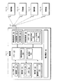
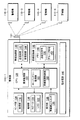
- FIG. 3 is a block diagram showing the configuration of the alarm device of the present embodiment.
- FIG. 3 shows a detailed circuit configuration of the alarm device 10-1 among the five alarm devices 10-1 to 10-5 shown in FIG.
- the alarm device 10-1 includes a CPU.
- a radio circuit unit 30 including an antenna 31, a recording circuit unit 32, a sensor unit 34, a notification unit 36, an operation unit 38, and a battery power source 40 are further provided. .
- the wireless circuit unit 30 is provided with a transmission circuit 42 and a reception circuit 44 so that event signals can be transmitted and received wirelessly between the other alarm devices 10-2 to 10-5.
- the radio circuit unit 30 in the case of Japan, for example, STD-30 (standard standard for radio equipment of a low power security system radio station) known as a standard of a specific low power radio station of 400 MHz band, or STD It is preferable to adopt a configuration compliant with T67 (standard for radio equipment for specific low power radio station telemeter, telecontrol and data transmission).
- the radio circuit unit 30 it is preferable to adopt a configuration conforming to the standard of the assigned radio station in the region for places other than Japan.
- the reception circuit 44 performs an intermittent reception operation.
- the intermittent reception cycle T12 of the reception circuit 44 is a cycle determined at the design stage of the alarm so as to obtain an average current consumption that ensures a battery life of 10 years, for example.
- the transmission circuit 42 and the reception circuit 44 of the present embodiment stop transmission and reception so as to extend the battery life by a control signal from the CPU 28 when a low battery is detected.
- the recording circuit unit 32 is provided with a memory 46.
- the memory 46 stores a transmission source code 50 serving as an ID (identifier) for identifying an alarm device, and a group code 52 for forming a group that performs a linked alarm with a plurality of alarm devices as shown in FIG. .
- the transmission source code 50 predicts the number of alarm devices provided in the country, and for example, a 26-bit code code is used so as not to overlap as the same code.
- the group code 52 is a code that is set in common to a plurality of alarm devices constituting the group, and the group code included in the event signal from another alarm device received by the wireless circuit unit 30 is registered in the memory 46. This event signal is received as a valid signal and processed when it matches the group code 52.
- the memory 46 is used for the recording circuit unit 32.
- a dip switch may be provided instead of the memory 46, and the transmission source code 50 and the group code 52 may be set by the dip switch. .
- the recording circuit unit 32 using a dip switch is desirable.
- the smoke detector 16 is provided in the sensor unit 34, and a smoke detection signal corresponding to the smoke density is output to the CPU 28.
- the sensor unit 34 may be provided with a thermistor that detects a temperature due to a fire.
- the sensor unit 34 is provided with a gas leak sensor.
- the notification unit 36 is provided with a speaker 56 and an LED 22.
- the speaker 56 outputs a voice message and an alarm sound from a voice synthesis circuit unit (not shown).
- the LED 22 displays an abnormality or failure such as a fire by blinking, blinking, or lighting.
- the alarm stop switch 20 is provided in the operation unit 38. When the alarm stop switch 20 is operated, the alarm sound flowing from the alarm device 10-1 can be stopped.
- the alarm stop switch 20 also serves as an inspection switch in this embodiment.
- the alarm stop switch 20 is effective when an alarm sound is output from the notification unit 36 through the speaker 56.
- the alarm stop switch 20 functions as an inspection switch, and when the inspection switch is pressed, a notification voice message or the like is output from the notification unit 36.
- the battery power source 40 uses, for example, an alkaline dry battery having a predetermined number of cells, and has a battery capacity of about 10 years due to low power consumption of the entire circuit unit including the wireless circuit unit 30 in the alarm device 10-1. Guarantee.
- the CPU 28 is provided with an abnormality monitoring unit 58 and a low battery monitoring unit 60 as functions realized by executing the program.
- the abnormality monitoring unit 58 is a sound that is an alarm sound indicating the link source from the speaker 56 of the notification unit 36.
- a message for example, “Woo Woo fire alarm has been activated Please confirm” is repeatedly output, and an event signal indicating a fire alarm is transmitted from the antenna 31 to another alarm device 10-by the transmission circuit 42 of the radio circuit unit 30. Send to 2 to 10-5.
- the abnormality monitoring unit 58 receives the event signal indicating the fire alarm from any of the other alarm devices 10-2 to 10-5 by the reception circuit 44 of the wireless circuit unit 30, and the speaker of the notification unit 36 As an alarm sound indicating the link destination from 56, for example, a voice message “Woo Woo, another fire alarm has been activated” should be output continuously.
- the LED 22 of the notification unit 36 is blinked, for example.
- the LED 22 of the notification unit 36 is blinked.
- the display of the LED 22 in the interlocking source alarm and the interlocking destination alarm can be distinguished.
- the blinking or flashing display of the same LED 22 may be used for both the interlocking source alarm and the interlocking destination alarm.
- the low battery monitoring unit 60 When the low battery monitoring unit 60 detects a low battery due to a voltage drop of the battery power supply 40, for example, once per minute, the low battery monitoring unit 60 emits a short low battery alarm sound such as “beep”, and transmits to the other alarm devices by the transmission circuit 42. Transmission and reception by the receiving circuit 44 from other alarm devices are stopped. Specifically, for example, a switch unit is provided in a power supply line for the transmission circuit 42 and the reception circuit 44, and the switch unit is opened to stop the power supply.
- the low battery monitoring unit 60 detects a low battery when the battery voltage of the battery power source 40 has dropped to a limit voltage that can function normally over a predetermined remaining time as an alarm.
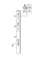
- FIG. 4 is an explanatory diagram showing the format of the event signal used in this embodiment.
- the event signal 48 includes a transmission source code 50, a group code 52, and an event code 54.
- the transmission source code 50 is a 26-bit code, for example.
- the group code 52 is, for example, an 8-bit code, and the same group code is set for, for example, the five alarm devices 10-1 to 10-5 in FIG. 3 constituting the same group.
- the same group code is set for each alarm device in the same group.
- a different group code may be used for each alarm device obtained from the calculation with the transmission source code.
- the event code 54 is a code representing an event content such as an abnormality or failure such as a fire or gas leak.
- a 3-bit code is used. For example, “001” is a fire, “010” is a gas leak, “011” is a failure, and the rest is reserved.
- the number of bits of the event code 54 can be increased to 4 bits and 5 bits when the type of event increases, thereby representing multiple types of event contents.
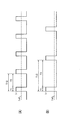
- FIG. 5 is a time chart showing the operations on the transmission side and the reception side at the normal time in the present embodiment.
- 5A shows the transmission operation of the transmission side alarm device
- FIG. 5B shows the reception operation of the reception side alarm device
- FIG. 5C shows the alarm output operation of the reception side alarm device.
- Receiving operation is being performed.
- the transmission side alarm shown in FIG. 5A issues a fire at an arbitrary timing
- an event signal indicating the fire is transmitted.
- the transmission time T3 of the fire alarm event signal is set to a time equal to or longer than the intermittent reception cycle T12.
- FIG. 6 is a time chart showing the relationship between the intermittent reception cycle and the average current consumption in the normal state.
- the receiving circuit 44 stops based on detection of a low battery, the average current Ia due to intermittent reception can be set to zero. Further, based on detection of the low battery, the transmission circuit 42 shown in FIG. 5A stops the transmission of the event signal to other alarm devices, and the current consumption of the battery power supply 40 is reduced accordingly. As a result, even when the battery power source 40 is in a low battery state, the battery life can be extended as much as possible.
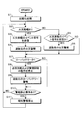
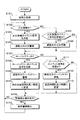
- FIG. 7 is a flowchart showing processing by the CPU 28 provided in the alarm device 10-1 of FIG.
- initialization processing is performed in step S1.
- This initial setting includes a process of setting a linked group by the alarm devices 10-1 to 10-5.
- the alarm device enters a monitoring state, and in step S2, the presence or absence of a fire alarm by the smoke detector 16 provided in the sensor unit 32 is determined.
- the process proceeds to step S3, and the fire alarm event signal is transmitted to the other alarm devices 10-2 to 10-5.
- the sound output from 56 and the lighting control of the LED 22 are output.
- step S2 the process proceeds to step S5, where it is determined whether or not a fire alarm event signal has been received from another alarm device, and the fire alarm event signal is received. If it is discriminated, a fire alarm of the interlocking destination is output in step S6.
- step S7 it is determined whether or not the low battery is detected in step S7, but in the normal time when no low battery is detected, the process proceeds to step S10.
- step S10 When the alarm stop operation during alarm is determined in step S10, the notification sound is stopped in step S11. To do.
- step S7 If it is determined in step S7 that the low battery is detected, the process proceeds to step S8, where the transmission circuit 42 transmits an event signal to another alarm device and the reception circuit 44 receives an event signal from the other alarm device. And the battery life of the battery power source 40 in which the low battery is detected is extended.
- said embodiment took the alarm device for fire detection as an example, the alarm which detects other abnormalities other than this, such as a gas leak alarm device and a security alarm device, is detected.
- the monitoring process including the preliminary abnormality of the present embodiment can be applied as it is for each device.
- it is applicable also to the alarm device of various uses, such as not only a house use but a building and an office use.
- the case where the sensor unit is provided integrally with the alarm device is taken as an example, but an alarm device provided with the sensor unit as a separate body from the alarm device may be used.
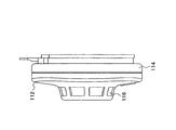
- FIG. 8A and 8B are explanatory views showing the appearance of the wireless alarm device according to the present embodiment, in which FIG. 8A shows a front view and FIG. 8B shows a side view.
- the alarm device 110 of this embodiment includes a cover 112 and a main body 114.
- a smoke detecting unit 116 having an opening serving as a smoke inlet is formed around the cover 112, and a fire is detected when smoke from the fire reaches a predetermined concentration.
- an acoustic hole 118 is provided on the lower left side of the smoke detector 116 of the cover 112.
- a speaker is incorporated behind the acoustic hole 118 so that an alarm sound and a voice message can be output through the acoustic hole 118.
- An alarm stop switch 120 is provided below the smoke detector 116. The alarm stop switch 120 also functions as an inspection switch.
- an LED 122 is arranged as indicated by a dotted line. When the LED 122 is turned on, the lighting state of the LED 122 can be recognized from the outside through the switch cover portion of the alarm stop switch 120.
- a mounting hook 115 is provided at the upper part on the back side of the main body 114, and a screw (not shown) or the like is screwed into the wall of the room to be installed, and the mounting hook 115 is attached to this screw, whereby the alarm device 110 can be installed on the wall surface. .
- the alarm device 110 shown in FIGS. 8A and 8B exemplifies a configuration in which smoke due to fire is detected by the smoke detector 116, but in addition, an alarm device including a thermistor that detects heat due to fire, Alarm devices that detect gas leaks other than fire are also included in the scope of the present invention.
- FIG. 9 is an explanatory diagram showing a state in which the alarm device of the present embodiment is installed in a house.
- the alarm devices 110-1 to 110-4 of this embodiment are installed in the kitchen, living room, main bedroom, and children's room of the house 124, and alarms are also given to the garage 126 that is built outdoors.
- a container 110-5 is installed.
- Each of the alarm devices 110-1 to 110-5 has a function of transmitting / receiving event signals to / from each other wirelessly.
- the five alarm devices 110-1 to 110-5 constitute a group, and The entire house 124 is being monitored for fire.
- the alarm device 110-4 detects the fire and starts an alarm. Detecting this fire and initiating an alarm is called “alarming” in the alarm.
- the alarm device 110-4 functions as a linkage source, and an event indicating a fire alert to the other alarm devices 110-1 to 110-3 and 110-5 that are linked destinations. Transmit the signal wirelessly.
- the other alarm devices 110-1 to 110-3, 110-5 receive the event signal indicating the fire alarm from the interlocking source alarm device 110-4, the alarm operation as the interlocking destination is performed.
- the alarm sound of the alarm device 110-4 that is the linkage source for example, “Please confirm that the Woo fire alarm has been activated” is continuously output by voice message.
- the alarm devices 110-1 to 110-3, 110-5 that are linked to continuously output a voice message such as “Please confirm that another fire alarm has been activated”.
- the alarm devices 110-1 to 110-5 have a low battery monitoring function for monitoring battery exhaustion.
- an alarm sound such as “beep” is intermittently output every predetermined time, Notify that a failure has occurred.
- the alarm device that has detected the low battery wirelessly transmits an event signal indicating the occurrence of the low battery to the other alarm devices, and the same low battery alarm is output from the other alarm devices.
- a fault alarm is output from all the alarm devices constituting the group that performs the interlocking alarm.
- the intermittent reception cycle T12 of the normal reception circuit 144 is changed to a longer intermittent reception cycle T14 to reduce current consumption. , Increase battery life.
- the transmission time T3 of the normal transmission circuit 142 is changed to a longer transmission time T5.
- the alarm devices 110-1 to 110-5 monitor sensor faults other than the low battery, and if a sensor fault is detected, the alarm devices 110-1 to 110-5 perform a linked alarm in the same manner as the low battery detection.
- FIG. 10 is a block diagram showing the alarm device of the present embodiment.
- FIG. 10 shows in detail the circuit configuration of the alarm device 110-1 among the five alarm devices 110-1 to 110-5 shown in FIG.
- the alarm device 110-1 includes a CPU 128.
- a wireless circuit unit 130 including an antenna 131, a recording circuit unit 132, a sensor unit 134, a notification unit 136, an operation unit 138, and a battery power source 140 are further provided.
- the wireless circuit unit 130 is provided with a transmission circuit 142 and a reception circuit 144 so that event signals can be transmitted and received wirelessly between the other alarm devices 110-2 to 110-5.
- a transmission circuit 142 and a reception circuit 144 so that event signals can be transmitted and received wirelessly between the other alarm devices 110-2 to 110-5.
- the radio circuit unit 130 in Japan for example, STD-30 (standard standard for radio equipment of a low power security system) known as a standard for a specific low power radio station in the 400 MHz band, or STD It is preferable to adopt a configuration compliant with T67 (standard for radio equipment for specific low power radio station telemeter, telecontrol and data transmission).
- the radio circuit unit 130 it is preferable to adopt a configuration conforming to the standard of the assigned radio station in the region for places other than Japan.
- the reception circuit 144 performs an intermittent reception operation.
- the intermittent reception cycle T12 of the reception circuit 144 is a cycle determined at the design stage of the alarm device so as to be an average current consumption for ensuring a battery life of 10 years, for example, and is a default cycle set at the shipment stage. ing.
- the receiving circuit 144 can change the preset default intermittent reception cycle T12 to a long intermittent reception cycle T13 in order to extend the battery life when a low battery is detected.
- the transmission time of the transmission circuit 142 of the alarm device that does not detect the low battery is changed from the normal transmission time T3 to the longer transmission time T5. .
- the recording circuit unit 132 is provided with a memory 146.
- the memory 146 stores a transmission source code 150 that is an ID (identifier) for identifying an alarm device, and a group code 152 for configuring a group that performs a linked alarm with a plurality of alarm devices as shown in FIG. .
- the transmission source code 150 the number of alarm devices provided in the country is predicted, and for example, a 26-bit code code is used so as not to be duplicated as the same code.
- the group code 152 is a code that is commonly set for a plurality of alarm devices constituting the group, and the group code included in the event signal from another alarm device received by the wireless circuit unit 130 is registered in the memory 146. When it matches the group code 152, this event signal is received as a valid signal and processed.
- the memory 146 is used for the recording circuit unit 132.
- a dip switch may be provided instead of the memory 146, and the transmission source code 150 and the group code 152 may be set by the dip switch. .
- the recording circuit unit 132 using a dip switch is desirable.
- the sensor unit 134 is provided with a smoke detector 116, which outputs a smoke detection signal corresponding to the smoke density to the CPU 128.
- the sensor unit 134 may be provided with a thermistor that detects a temperature due to a fire.
- a gas leakage sensor is provided in the sensor unit 134.
- the notification unit 136 is provided with a speaker 156 and an LED 122.
- the speaker 156 outputs a voice message and an alarm sound from a voice synthesis circuit unit (not shown).
- the LED 122 displays an abnormality and a failure such as a fire by blinking, blinking, or lighting.
- the operation unit 138 is provided with an alarm stop switch 120 and a transmission / reception time control unit 62.
- the alarm stop switch 120 When the alarm stop switch 120 is operated, the alarm sound flowing from the alarm device 110-1 can be stopped.
- the alarm stop switch 120 also serves as an inspection switch in this embodiment.
- the alarm stop switch 120 is effective when an alarm sound is output from the notification unit 136 through the speaker 156.
- the alarm stop switch 120 functions as an inspection switch, and when the inspection switch is pressed, a notification voice message or the like is output from the notification unit 136.
- the battery power supply 140 uses, for example, an alkaline dry battery having a predetermined number of cells, and the battery capacity is about 10 years due to low power consumption of the entire circuit unit including the wireless circuit unit 130 in the alarm device 110-1. Guarantee.
- the CPU 128 is provided with an abnormality monitoring unit 158, a low battery monitoring unit 160, and a transmission / reception time control unit 162 as functions realized by executing the program.
- the abnormality monitoring unit 158 When the smoke detection signal from the smoke detection unit 116 provided in the sensor unit 134 exceeds the fire level and detects a fire, the abnormality monitoring unit 158 generates an alarm sound indicating the interlock source from the speaker 156 of the notification unit 136, for example, “ “Woo Woo fire alarm activated Please confirm” is repeatedly output, and the event signal indicating the fire alarm is transmitted from the antenna 31 to the other alarm devices 110-2 to 110-5 by the transmission circuit 142 of the radio circuit unit 130. To send to.
- the abnormality monitoring unit 158 receives the event signal indicating the fire alarm from any of the other alarm devices 110-2 to 110-5 by the reception circuit 144 of the wireless circuit unit 130, and the speaker of the notification unit 136 From 156, an audible alarm indicating the link destination, for example, “Woooo, another fire alarm has been activated. Please confirm” is output continuously.
- the LED 122 of the notification unit 136 is blinked, for example.
- the LED 122 of the notification unit 136 is blinked.
- the display of the LED 122 in the interlocking source alarm and the interlocking destination alarm can be distinguished.
- the blinking or blinking display of the same LED 122 may be used for both the interlocking source alarm and the interlocking destination alarm.
- the low battery monitoring unit 160 When the low battery monitoring unit 160 detects a low battery due to a voltage drop of the battery power supply 140, for example, once per minute, the low battery monitoring unit 160 emits a short low battery alarm sound such as “beep” and sends an event signal indicating the low battery to another Transmit to alarm devices 110-2 to 110-5.
- a short low battery alarm sound such as “beep”
- the low battery monitoring unit 160 detects a low battery when the battery voltage of the battery power supply 140 drops to a limit voltage that can function normally over a predetermined remaining time as an alarm.
- the low battery monitoring unit 160 when the low battery monitoring unit 160 receives an event signal indicating a low battery from any of the other alarm devices 110-2 to 110-5, the low battery monitoring unit 160 also intermittently emits a low battery warning sound, Performs alarm sound interlocking output. Regarding the alarm at the low battery interlocking destination, the LED 122 may blink in synchronization with the alarm sound.
- the transmission / reception time control unit 162 When detecting a low battery, the transmission / reception time control unit 162 changes the reception period T12 of the reception circuit 44 that is initially set to a long period T13 to extend the battery life, while indicating a low battery from another alarm device.
- the transmission time T3 of the transmission circuit 142 that is initially set is changed to a transmission time T5 that is equal to or longer than the changed intermittent reception cycle T13.
- FIG. 11 is an explanatory diagram showing a format of an event signal used in the present embodiment.
- the event signal 148 includes a transmission source code 150, a group code 152, and an event code 154.
- the transmission source code 150 is a 26-bit code, for example.
- the group code 152 is an 8-bit code, for example, and the same group code is set for, for example, the five alarm devices 110-1 to 110-5 in FIG.
- group code 152 in addition to setting the same group code for the alarm devices of the same group, a predetermined reference code common to the alarm devices constituting the group and a transmission source code unique to each alarm device A different group code may be used for each alarm device obtained from the calculation.
- the event code 154 is a code representing the event content such as an abnormality or failure such as a fire or gas leak.
- a 3-bit code is used. For example, “001” is a fire, “010” is a gas leak, “011” is a low battery, and the rest is reserved.
- the number of bits of the event code 154 can be expressed as a plurality of types of event contents by further increasing to 4 bits and 5 bits when the types of events increase.
- FIG. 12 is a time chart showing operations on the transmission side and the reception side in the normal time in the present embodiment.
- 12A shows the transmission operation of the transmission side alarm device
- FIG. 12B shows the reception operation of the reception side alarm device
- FIG. 12C shows the alarm output operation of the reception side alarm device.
- FIG. 13 is a time chart showing operations on the transmission side and the reception side when a low battery is detected in the present embodiment.
- 13A shows the transmission operation of the transmission side alarm device
- FIG. 13B shows the reception operation of the reception side alarm device
- FIG. 13C shows the alarm output operation of the reception side alarm device.
- FIG. 14 is a time chart showing the relationship between the intermittent reception period and the average current consumption in the present embodiment.
- FIG. 14A shows the intermittent reception operation in the normal intermittent reception cycle T12.
- the intermittent reception cycle T12 is changed to a long intermittent reception cycle T14 when a low battery is detected, so that even when the battery power supply 140 is in a low battery state, the consumption current of the reception circuit 144 is reduced and the battery life is possible. It can be extended as long as possible.
- FIG. 15 is a flowchart showing processing by the CPU 128 provided in the alarm device 110-1 of FIG.
- initialization processing is performed in step S101.
- This initial setting includes a process of setting a linked group by the alarm devices 110-1 to 110-5.
- the alarm device enters a monitoring state, and in step S102, the presence / absence of a fire alarm by the smoke detector 116 provided in the sensor unit 132 is determined. If a fire alarm is determined, the process proceeds to step S103, and an event signal of the fire alarm is transmitted to the other alarm devices 110-2 to 110-5, and then the fire alarm of the interlocking source is notified to the speaker of the notification unit 136 in step S104.
- the sound is output from the sound output from 156 and the lighting control of the LED 122.
- step S102 if a fire alarm is not determined in step S102, the process proceeds to step S105, where it is determined whether or not a fire alarm event signal has been received from another alarm device, and a fire alarm event signal is received. Is determined, a fire alarm at the interlock destination is output in step S106.
- step S107 it is determined whether or not the low battery is detected. If low battery detection is determined, the process proceeds to step S108, and an event signal indicating the low battery is transmitted to the other alarm devices 110-2 to 110-5. After that, in step S109, an intermittent interlocking low battery alarm is output.
- step S110 the intermittent reception cycle of the reception circuit 144 is changed from the initially set cycle T12 to, for example, a double cycle T14.
- step S111 it is determined in step S111 whether or not an event signal indicating a low battery has been received from the other alarm devices 110-1 to 110-5. If an event signal indicating a low battery is received, an intermittent interlock low battery alarm is output in step S112.
- step S113 the reception operation time of the transmission circuit 144 is changed from the normal T3 time to a longer T5 time.
- step S114 when an alarm stop operation during an alarm is determined in step S114, the notification sound is stopped in step S115.
- said embodiment took the alarm device for fire detection as an example, the alarm which detects other abnormalities other than this, such as a gas leak alarm device and a security alarm device, is detected.
- the monitoring process including the preliminary abnormality of the present embodiment can be applied as it is for each device.
- it is applicable also to the alarm device of various uses, such as not only a house use but a building and an office use.
- the said embodiment took the case where the sensor part was integrally provided in the alarm device as an example, as another embodiment, it is an alarm device in which the sensor part is provided separately from the alarm device. Also good.
- the present invention is not limited to the above-described embodiment, includes appropriate modifications that do not impair the object and advantages thereof, and is not limited only by the numerical values shown in the above-described embodiment.
- the remaining period until the battery runs out can be extended as much as possible to improve reliability.
Landscapes
- Physics & Mathematics (AREA)
- General Physics & Mathematics (AREA)
- Business, Economics & Management (AREA)
- Emergency Management (AREA)
- Engineering & Computer Science (AREA)
- Computer Security & Cryptography (AREA)
- Alarm Systems (AREA)
- Fire Alarms (AREA)
Abstract
Description
本出願は、日本国実願2008-002727号と日本国実願2008-002728号とを基礎出願とし、それらの内容をここに取り込む。 The present invention relates to an alarm device that detects an abnormality such as a fire and issues an alarm and wirelessly transmits a signal to another alarm device to output an alarm in conjunction with the alarm device.
This application is based on Japanese application Nos. 2008-002727 and 2008-002728, the contents of which are incorporated herein.
12 カバー
14 本体
15 取付フック
16 検煙部
18 音響孔
20 警報停止スイッチ
22 LED
24 住宅
26 ガレージ
28 CPU
30 無線回路部
31 アンテナ
32 記録回路部
34 センサ部
36 報知部
38 操作部
40 電池電源
42 送信回路
44 受信回路
46 メモリ
48 イベント信号
50 送信元符号
52 グループ符号
54 イベント符号
56 スピーカ
58 異常監視部
60 ローバッテリー監視部
110,110-1~110-5 警報器
112 カバー
114 本体
115 取付フック
116 検煙部
118 音響孔
120 警報停止スイッチ
122 LED
124 住宅
126 ガレージ
128 CPU
130 無線回路部
131 アンテナ
132 記録回路部
134 センサ部
136 報知部
138 操作部
140 電池電源
142 送信回路
144 受信回路
146 メモリ
148 イベント信号
150 送信元符号
152 グループ符号
154 イベント符号
156 スピーカ
158 異常監視部
160 ローバッテリー監視部
162 送受信時間制御部 10, 10-1 to 10-5
24
DESCRIPTION OF SYMBOLS 30
124
DESCRIPTION OF SYMBOLS 130 Radio |
図1A及び図1Bは本発明による無線式の警報器の外観を示し、図1Aが正面図を、図1Bが側面図を示している。 (First embodiment)
1A and 1B show the appearance of a wireless alarm device according to the present invention, FIG. 1A shows a front view, and FIG. 1B shows a side view.
Ia=(Ir×T1)/T12
で与えられる。 FIG. 6 is a time chart showing the relationship between the intermittent reception cycle and the average current consumption in the normal state. In this case, the average current Ia is
Ia = (Ir × T1) / T12
Given in.
図8A及び図8Bは、本実施形態に係る無線式の警報器の外観を示す説明図であり、図8Aが正面図を、図8Bに側面図を示している。 (Second Embodiment)
8A and 8B are explanatory views showing the appearance of the wireless alarm device according to the present embodiment, in which FIG. 8A shows a front view and FIG. 8B shows a side view.
Ia1=(Ir×T1)/T12
で与えられる。 FIG. 14 is a time chart showing the relationship between the intermittent reception period and the average current consumption in the present embodiment. FIG. 14A shows the intermittent reception operation in the normal intermittent reception cycle T12. In this case, the average current Ia1 is Ia1 = (Ir × T1) / T12.
Given in.
Ia2=(Ir×T1)/T14
で与えられる。 FIG. 14B shows a case where the intermittent reception cycle T12 is changed to a long intermittent reception cycle T14 based on detection of a low battery, and the average current consumption Ia2 in this case is Ia2 = (Ir × T1) / T14.
Given in.
Claims (3)
- 電池電源と;
異常を検出した場合に異常検出信号を出力するセンサ部と;
前記異常検出信号に基づいて警報を出力する報知部と;
他の警報器からのイベント信号を所定の受信周期毎に間欠的に受信する受信回路部と;
前記所定の受信周期以上の送信時間でイベント信号を前記他の警報器に送信する送信回路部と;
前記センサ部が異常を検出したときに、前記異常検出信号に基づいて前記報知部に前記異常警報を出力させ、かつ、前記警報器の異常に係るイベント信号を前記送信回路部より前記他の警報器へ送信させ、一方、前記他の警報器からの前記他の警報器の異常に係るイベント信号を前記受信回路部が受信したときに、前記報知部に前記異常警報を出力させる異常監視部と;
前記電池電源の電圧低下を検出したときに、前記警報器のローバッテリー警報を前記報知部より出力させると共に、前記受信回路部および前記送信回路部における前記イベント信号の送受信を止めるローバッテリー監視部と;
を備える
ことを特徴とする警報器。 With battery power;
A sensor unit that outputs an abnormality detection signal when an abnormality is detected;
A notification unit that outputs an alarm based on the abnormality detection signal;
A receiving circuit section that intermittently receives event signals from other alarm devices at predetermined reception intervals;
A transmission circuit unit that transmits an event signal to the other alarm device at a transmission time equal to or longer than the predetermined reception cycle;
When the sensor unit detects an abnormality, the alarm unit outputs the abnormality alarm based on the abnormality detection signal, and an event signal related to the abnormality of the alarm device is transmitted from the transmission circuit unit to the other alarm. An abnormality monitoring unit that, when the receiving circuit unit receives an event signal related to an abnormality of the other alarm device from the other alarm device, outputs the abnormality alarm to the notification unit; ;
A low battery monitoring unit that outputs a low battery alarm of the alarm device from the notification unit when detecting a voltage drop of the battery power source, and stops transmission and reception of the event signal in the reception circuit unit and the transmission circuit unit; ;
An alarm device comprising: - 電池電源と;
異常を検出した場合に異常検出信号を出力するセンサ部と;
前記異常検出信号に基づいて異常警報を出力する報知部と;
他の警報器からのイベント信号を所定の受信周期毎に間欠的に受信する受信回路部と;
前記所定の受信周期以上の送信時間でイベント信号を前記他の警報器に送信する送信回路部と;
前記センサ部が異常を検出したときに、前記異常検出信号に基づいて前記報知部に前記異常警報を出力させ、かつ、前記警報器の異常に係るイベント信号を前記送信回路部より前記他の警報器へ送信させ、一方、前記他の警報器からの前記他の警報器の異常に係るイベント信号を前記受信回路部が受信したときに、前記報知部に前記異常警報を出力させる異常監視部と;
前記警報器および前記他の警報器の電圧低下を知らせるローバッテリー警報を前記報知部より出力させるローバッテリー監視部と;
前記送信回路部の前記送信時間および前記受信回路部の前記所定の受信周期を制御する送受信時間制御部と;を備え、
前記電池電源の電圧低下を検出したときに、前記ローバッテリー監視部が、前記警報器のローバッテリー警報を前記報知部に出力させると共に、前記警報器の電圧低下に係るイベント信号を前記他の警報器より前記送信回路部に送信させ、前記送受信時間制御部が、前記受信回路部の前記所定の受信周期よりも長い受信周期に変更し;
前記他の警報器から前記他の警報器の電圧低下に係るイベント信号を受信したときに、前記ローバッテリー監視部が、前記他の警報器のローバッテリー警報を前記報知部に出力させ、前記送受信時間制御部が、前記送信回路部の前期送信時間を前記長い受信周期以上の時間に変更する;
ことを特徴とする警報器。 With battery power;
A sensor unit that outputs an abnormality detection signal when an abnormality is detected;
A notification unit that outputs an abnormality alarm based on the abnormality detection signal;
A receiving circuit section that intermittently receives event signals from other alarm devices at predetermined reception intervals;
A transmission circuit unit that transmits an event signal to the other alarm device at a transmission time equal to or longer than the predetermined reception cycle;
When the sensor unit detects an abnormality, the alarm unit outputs the abnormality alarm based on the abnormality detection signal, and an event signal related to the abnormality of the alarm device is transmitted from the transmission circuit unit to the other alarm. An abnormality monitoring unit that, when the receiving circuit unit receives an event signal related to an abnormality of the other alarm device from the other alarm device, outputs the abnormality alarm to the notification unit; ;
A low battery monitoring unit for outputting a low battery alarm from the notification unit to notify a voltage drop of the alarm device and the other alarm device;
A transmission / reception time control unit for controlling the transmission time of the transmission circuit unit and the predetermined reception cycle of the reception circuit unit;
When detecting a voltage drop of the battery power source, the low battery monitoring unit causes the alarm unit to output a low battery alarm of the alarm device, and an event signal related to the voltage drop of the alarm device is output to the other alarm device. And the transmission / reception time control unit changes the reception cycle to be longer than the predetermined reception cycle of the reception circuit unit;
When the event signal relating to the voltage drop of the other alarm device is received from the other alarm device, the low battery monitoring unit causes the low battery alarm of the other alarm device to be output to the notification unit, and the transmission / reception is performed. The time control unit changes the previous transmission time of the transmission circuit unit to a time longer than the long reception period;
An alarm device characterized by that. - 前記ローバッテリー監視部が、前記電池電圧が前記警報器の正常な機能を所定残り時間に亘り維持可能な限界電圧まで低下したときに、前記電圧低下を検出する請求項1または2に記載の警報器。 3. The alarm according to claim 1, wherein the low battery monitoring unit detects the voltage drop when the battery voltage drops to a limit voltage at which a normal function of the alarm device can be maintained for a predetermined remaining time. vessel.
Priority Applications (4)
| Application Number | Priority Date | Filing Date | Title |
|---|---|---|---|
| EP09738663.5A EP2284815B1 (en) | 2008-04-28 | 2009-03-17 | Alarm device |
| AU2009241098A AU2009241098B2 (en) | 2008-04-28 | 2009-03-17 | Alarm device |
| CN2009801140124A CN102016942A (en) | 2008-04-28 | 2009-03-17 | Alarm device |
| US12/936,989 US8514091B2 (en) | 2008-04-28 | 2009-03-17 | Multiple alarm system with low battery detection for controlling transmission and reception of an alarm signal |
Applications Claiming Priority (4)
| Application Number | Priority Date | Filing Date | Title |
|---|---|---|---|
| JP2008-002727U | 2008-04-28 | ||
| JP2008002728U JP3143140U (en) | 2008-04-28 | 2008-04-28 | Alarm |
| JP2008002727U JP3143139U (en) | 2008-04-28 | 2008-04-28 | Alarm |
| JP2008-002728U | 2008-04-28 |
Publications (1)
| Publication Number | Publication Date |
|---|---|
| WO2009133726A1 true WO2009133726A1 (en) | 2009-11-05 |
Family
ID=41254949
Family Applications (1)
| Application Number | Title | Priority Date | Filing Date |
|---|---|---|---|
| PCT/JP2009/055194 WO2009133726A1 (en) | 2008-04-28 | 2009-03-17 | Alarm device |
Country Status (6)
| Country | Link |
|---|---|
| US (1) | US8514091B2 (en) |
| EP (2) | EP2618318A3 (en) |
| KR (1) | KR20110004395A (en) |
| CN (1) | CN102016942A (en) |
| AU (1) | AU2009241098B2 (en) |
| WO (1) | WO2009133726A1 (en) |
Cited By (3)
| Publication number | Priority date | Publication date | Assignee | Title |
|---|---|---|---|---|
| JP2010267294A (en) * | 2010-07-22 | 2010-11-25 | Hochiki Corp | Alarm |
| WO2014147982A1 (en) * | 2013-03-21 | 2014-09-25 | 株式会社デンソー | Vehicle-mounted emergency report device |
| WO2019230153A1 (en) * | 2018-05-29 | 2019-12-05 | パナソニックIpマネジメント株式会社 | Abnormality alarm device |
Families Citing this family (8)
| Publication number | Priority date | Publication date | Assignee | Title |
|---|---|---|---|---|
| US8310366B2 (en) * | 2008-12-18 | 2012-11-13 | Symbol Technologies, Inc. | RFID device and related method for providing assistance for locating it |
| JP5792645B2 (en) | 2012-01-13 | 2015-10-14 | ルネサスエレクトロニクス株式会社 | Semiconductor device and control method thereof |
| JP6427772B2 (en) | 2013-12-26 | 2018-11-28 | オプテックス株式会社 | Battery-powered security device |
| US10057850B2 (en) * | 2014-03-24 | 2018-08-21 | Acer Incorporated | Methods for deferring communications between a mobile communication device and a service network |
| CN104851222B (en) * | 2015-05-28 | 2017-07-18 | 深圳市欣横纵数码科技有限公司 | A kind of NVSG relates to the management method of vouching position comprehensive security management system |
| CN106600908A (en) * | 2017-01-24 | 2017-04-26 | 江苏友穗传感科技股份有限公司 | Battery-driven low-power gas leakage alarm device |
| WO2020160967A1 (en) * | 2019-02-06 | 2020-08-13 | British Telecommunications Public Limited Company | Network device management |
| CN112017410A (en) * | 2019-05-28 | 2020-12-01 | 瑞昱半导体股份有限公司 | Event alarm and event alarm system |
Citations (5)
| Publication number | Priority date | Publication date | Assignee | Title |
|---|---|---|---|---|
| JP2006350412A (en) * | 2005-06-13 | 2006-12-28 | Hochiki Corp | Alarm device |
| JP2007011828A (en) * | 2005-07-01 | 2007-01-18 | Hochiki Corp | Alarm unit |
| JP2007094719A (en) | 2005-09-28 | 2007-04-12 | Yazaki Corp | Wireless device |
| JP2008002728A (en) | 2006-06-21 | 2008-01-10 | Matsushita Electric Ind Co Ltd | Refrigerator |
| JP2008002727A (en) | 2006-06-21 | 2008-01-10 | Matsushita Electric Ind Co Ltd | Air conditioner |
Family Cites Families (12)
| Publication number | Priority date | Publication date | Assignee | Title |
|---|---|---|---|---|
| JPH03201196A (en) * | 1989-12-28 | 1991-09-03 | Hochiki Corp | Radio type alarm system |
| JP2857196B2 (en) * | 1990-01-25 | 1999-02-10 | 松下電器産業株式会社 | Wireless monitoring device |
| JP2773375B2 (en) * | 1990-04-04 | 1998-07-09 | 松下電器産業株式会社 | Transmitting device, receiving device, and transmitting / receiving device |
| US5587705A (en) * | 1994-08-29 | 1996-12-24 | Morris; Gary J. | Multiple alert smoke detector |
| JP3374712B2 (en) * | 1997-08-08 | 2003-02-10 | 三菱電機株式会社 | Wireless communication terminal |
| CA2346638C (en) * | 1998-10-06 | 2009-01-20 | Interlogix, Inc. | Wireless home fire and security alarm system |
| DE10138229B4 (en) * | 2001-08-03 | 2009-10-01 | Siemens Gebäudesicherheit GmbH & Co. oHG | Method for radio transmission in a hazard detection system |
| US20070149139A1 (en) * | 2004-06-10 | 2007-06-28 | Jean-Louis Gauvreau | Wireless Network System with Energy Management |
| EP1803102B1 (en) * | 2004-10-18 | 2011-04-06 | Walter Kidde Portable Equipment, Inc. | Frequency communications scheme in life safety devices |
| JP2006270505A (en) * | 2005-03-24 | 2006-10-05 | Nohmi Bosai Ltd | Signal transmission system for transmission system |
| US7554439B2 (en) * | 2006-10-11 | 2009-06-30 | Lookout Portable Security | Remote monitor system with radio dispatch |
| GB2443021A (en) * | 2006-10-18 | 2008-04-23 | Ian Hinds | Monitoring System using Multi-Hop Mesh Networks |
-
2009
- 2009-03-17 KR KR1020107023823A patent/KR20110004395A/en not_active Application Discontinuation
- 2009-03-17 EP EP13164058.3A patent/EP2618318A3/en not_active Ceased
- 2009-03-17 AU AU2009241098A patent/AU2009241098B2/en not_active Ceased
- 2009-03-17 US US12/936,989 patent/US8514091B2/en active Active
- 2009-03-17 EP EP09738663.5A patent/EP2284815B1/en active Active
- 2009-03-17 WO PCT/JP2009/055194 patent/WO2009133726A1/en active Application Filing
- 2009-03-17 CN CN2009801140124A patent/CN102016942A/en active Pending
Patent Citations (5)
| Publication number | Priority date | Publication date | Assignee | Title |
|---|---|---|---|---|
| JP2006350412A (en) * | 2005-06-13 | 2006-12-28 | Hochiki Corp | Alarm device |
| JP2007011828A (en) * | 2005-07-01 | 2007-01-18 | Hochiki Corp | Alarm unit |
| JP2007094719A (en) | 2005-09-28 | 2007-04-12 | Yazaki Corp | Wireless device |
| JP2008002728A (en) | 2006-06-21 | 2008-01-10 | Matsushita Electric Ind Co Ltd | Refrigerator |
| JP2008002727A (en) | 2006-06-21 | 2008-01-10 | Matsushita Electric Ind Co Ltd | Air conditioner |
Non-Patent Citations (1)
| Title |
|---|
| See also references of EP2284815A4 * |
Cited By (5)
| Publication number | Priority date | Publication date | Assignee | Title |
|---|---|---|---|---|
| JP2010267294A (en) * | 2010-07-22 | 2010-11-25 | Hochiki Corp | Alarm |
| WO2014147982A1 (en) * | 2013-03-21 | 2014-09-25 | 株式会社デンソー | Vehicle-mounted emergency report device |
| JP2014182747A (en) * | 2013-03-21 | 2014-09-29 | Denso Corp | Vehicle-mounted emergency report device |
| US9616835B2 (en) | 2013-03-21 | 2017-04-11 | Denso Corporation | Vehicle-mounted emergency report device |
| WO2019230153A1 (en) * | 2018-05-29 | 2019-12-05 | パナソニックIpマネジメント株式会社 | Abnormality alarm device |
Also Published As
| Publication number | Publication date |
|---|---|
| EP2284815B1 (en) | 2013-06-19 |
| EP2618318A3 (en) | 2013-11-13 |
| KR20110004395A (en) | 2011-01-13 |
| AU2009241098B2 (en) | 2013-08-22 |
| AU2009241098A1 (en) | 2009-11-05 |
| EP2284815A4 (en) | 2011-05-04 |
| EP2618318A2 (en) | 2013-07-24 |
| US20110037603A1 (en) | 2011-02-17 |
| CN102016942A (en) | 2011-04-13 |
| EP2284815A1 (en) | 2011-02-16 |
| US8514091B2 (en) | 2013-08-20 |
Similar Documents
| Publication | Publication Date | Title |
|---|---|---|
| WO2009133726A1 (en) | Alarm device | |
| JP5307126B2 (en) | Alarm | |
| JP5074282B2 (en) | Alarm | |
| JP3143139U (en) | Alarm | |
| JP3143138U (en) | Alarm | |
| JP3143140U (en) | Alarm | |
| JP5266078B2 (en) | Alarm system and alarm | |
| JP3189065U (en) | Alarm | |
| JP5781792B2 (en) | Alarm and monitoring system | |
| JP5266315B2 (en) | Alarm | |
| JP5280898B2 (en) | Alarm | |
| JP5744577B2 (en) | Alarm and monitoring system | |
| JP5296032B2 (en) | Alarm | |
| JP5744438B2 (en) | Alarm system and transmitter | |
| JP4944229B2 (en) | Alarm | |
| JP5878707B2 (en) | Monitoring system and alarm | |
| JP2010020663A (en) | Alarm | |
| JP5507928B2 (en) | Alarm and alarm system | |
| JP5343143B2 (en) | Alarm | |
| JP5536938B2 (en) | Alarm | |
| JP5893835B2 (en) | Alarm and monitoring system | |
| JP2012022361A (en) | Warning system and transmitter | |
| JP2011044172A (en) | Alarm | |
| JP3190621U (en) | Alarm | |
| JP2010250716A (en) | Alarm |
Legal Events
| Date | Code | Title | Description |
|---|---|---|---|
| WWE | Wipo information: entry into national phase |
Ref document number: 200980114012.4 Country of ref document: CN |
|
| 121 | Ep: the epo has been informed by wipo that ep was designated in this application |
Ref document number: 09738663 Country of ref document: EP Kind code of ref document: A1 |
|
| WWE | Wipo information: entry into national phase |
Ref document number: 12936989 Country of ref document: US |
|
| ENP | Entry into the national phase |
Ref document number: 20107023823 Country of ref document: KR Kind code of ref document: A |
|
| WWE | Wipo information: entry into national phase |
Ref document number: 2009241098 Country of ref document: AU |
|
| WWE | Wipo information: entry into national phase |
Ref document number: 2009738663 Country of ref document: EP |
|
| NENP | Non-entry into the national phase |
Ref country code: DE |
|
| ENP | Entry into the national phase |
Ref document number: 2009241098 Country of ref document: AU Date of ref document: 20090317 Kind code of ref document: A |