WO2009107572A1 - Waste liquid recovering body - Google Patents
Waste liquid recovering body Download PDFInfo
- Publication number
- WO2009107572A1 WO2009107572A1 PCT/JP2009/053135 JP2009053135W WO2009107572A1 WO 2009107572 A1 WO2009107572 A1 WO 2009107572A1 JP 2009053135 W JP2009053135 W JP 2009053135W WO 2009107572 A1 WO2009107572 A1 WO 2009107572A1
- Authority
- WO
- WIPO (PCT)
- Prior art keywords
- waste ink
- ink tank
- connection terminal
- waste
- opening
- Prior art date
Links
- 239000002699 waste material Substances 0.000 title claims abstract description 403
- 239000007788 liquid Substances 0.000 title claims abstract description 99
- 238000011084 recovery Methods 0.000 claims description 60
- 238000003780 insertion Methods 0.000 claims description 17
- 230000037431 insertion Effects 0.000 claims description 17
- 238000000605 extraction Methods 0.000 claims description 11
- 238000007599 discharging Methods 0.000 abstract description 15
- 239000011358 absorbing material Substances 0.000 description 135
- 239000002585 base Substances 0.000 description 40
- 238000003860 storage Methods 0.000 description 32
- 238000004891 communication Methods 0.000 description 28
- 230000007246 mechanism Effects 0.000 description 26
- 230000002093 peripheral effect Effects 0.000 description 21
- 238000010521 absorption reaction Methods 0.000 description 15
- 239000006096 absorbing agent Substances 0.000 description 13
- 230000004048 modification Effects 0.000 description 11
- 238000012986 modification Methods 0.000 description 11
- NJPPVKZQTLUDBO-UHFFFAOYSA-N novaluron Chemical compound C1=C(Cl)C(OC(F)(F)C(OC(F)(F)F)F)=CC=C1NC(=O)NC(=O)C1=C(F)C=CC=C1F NJPPVKZQTLUDBO-UHFFFAOYSA-N 0.000 description 11
- 239000002904 solvent Substances 0.000 description 9
- 210000000078 claw Anatomy 0.000 description 8
- 238000006073 displacement reaction Methods 0.000 description 7
- 230000000694 effects Effects 0.000 description 6
- 238000003825 pressing Methods 0.000 description 6
- 238000007789 sealing Methods 0.000 description 6
- 239000000463 material Substances 0.000 description 5
- 238000000034 method Methods 0.000 description 5
- 230000000149 penetrating effect Effects 0.000 description 5
- 229920005989 resin Polymers 0.000 description 5
- 239000011347 resin Substances 0.000 description 5
- 230000004308 accommodation Effects 0.000 description 4
- 238000004140 cleaning Methods 0.000 description 4
- 230000007423 decrease Effects 0.000 description 4
- 238000009792 diffusion process Methods 0.000 description 4
- 239000012530 fluid Substances 0.000 description 4
- 238000012423 maintenance Methods 0.000 description 4
- 230000003014 reinforcing effect Effects 0.000 description 4
- 229920006395 saturated elastomer Polymers 0.000 description 4
- 239000000499 gel Substances 0.000 description 3
- 238000004519 manufacturing process Methods 0.000 description 3
- 239000012466 permeate Substances 0.000 description 3
- 239000000758 substrate Substances 0.000 description 3
- 238000009834 vaporization Methods 0.000 description 3
- 230000008016 vaporization Effects 0.000 description 3
- 230000002745 absorbent Effects 0.000 description 2
- 239000002250 absorbent Substances 0.000 description 2
- 230000015572 biosynthetic process Effects 0.000 description 2
- 230000000052 comparative effect Effects 0.000 description 2
- 230000005484 gravity Effects 0.000 description 2
- 239000011344 liquid material Substances 0.000 description 2
- 239000002184 metal Substances 0.000 description 2
- 230000003287 optical effect Effects 0.000 description 2
- 230000008569 process Effects 0.000 description 2
- 230000001105 regulatory effect Effects 0.000 description 2
- 239000000243 solution Substances 0.000 description 2
- -1 that is Substances 0.000 description 2
- 238000000018 DNA microarray Methods 0.000 description 1
- 125000002066 L-histidyl group Chemical group [H]N1C([H])=NC(C([H])([H])[C@](C(=O)[*])([H])N([H])[H])=C1[H] 0.000 description 1
- 238000009825 accumulation Methods 0.000 description 1
- 239000002253 acid Substances 0.000 description 1
- 239000003513 alkali Substances 0.000 description 1
- 238000013459 approach Methods 0.000 description 1
- 230000008859 change Effects 0.000 description 1
- 238000005520 cutting process Methods 0.000 description 1
- 238000001035 drying Methods 0.000 description 1
- 239000000428 dust Substances 0.000 description 1
- 239000007772 electrode material Substances 0.000 description 1
- 238000005401 electroluminescence Methods 0.000 description 1
- 238000005530 etching Methods 0.000 description 1
- 238000001704 evaporation Methods 0.000 description 1
- 238000002347 injection Methods 0.000 description 1
- 239000007924 injection Substances 0.000 description 1
- 239000003049 inorganic solvent Substances 0.000 description 1
- 229910001867 inorganic solvent Inorganic materials 0.000 description 1
- 239000004973 liquid crystal related substance Substances 0.000 description 1
- 229910001338 liquidmetal Inorganic materials 0.000 description 1
- 239000000314 lubricant Substances 0.000 description 1
- 239000008204 material by function Substances 0.000 description 1
- 230000013011 mating Effects 0.000 description 1
- 238000002156 mixing Methods 0.000 description 1
- 239000004745 nonwoven fabric Substances 0.000 description 1
- 239000005416 organic matter Substances 0.000 description 1
- 239000003960 organic solvent Substances 0.000 description 1
- 239000002245 particle Substances 0.000 description 1
- 238000007639 printing Methods 0.000 description 1
- 239000000047 product Substances 0.000 description 1
- 230000004044 response Effects 0.000 description 1
- 230000000717 retained effect Effects 0.000 description 1
- 230000008961 swelling Effects 0.000 description 1
- 229920003002 synthetic resin Polymers 0.000 description 1
- 239000000057 synthetic resin Substances 0.000 description 1
- 238000011144 upstream manufacturing Methods 0.000 description 1
Images


Classifications
-
- B—PERFORMING OPERATIONS; TRANSPORTING
- B41—PRINTING; LINING MACHINES; TYPEWRITERS; STAMPS
- B41J—TYPEWRITERS; SELECTIVE PRINTING MECHANISMS, i.e. MECHANISMS PRINTING OTHERWISE THAN FROM A FORME; CORRECTION OF TYPOGRAPHICAL ERRORS
- B41J2/00—Typewriters or selective printing mechanisms characterised by the printing or marking process for which they are designed
- B41J2/005—Typewriters or selective printing mechanisms characterised by the printing or marking process for which they are designed characterised by bringing liquid or particles selectively into contact with a printing material
- B41J2/01—Ink jet
- B41J2/17—Ink jet characterised by ink handling
- B41J2/1721—Collecting waste ink; Collectors therefor
- B41J2/1742—Open waste ink collectors, e.g. ink receiving from a print head above the collector during borderless printing
-
- B—PERFORMING OPERATIONS; TRANSPORTING
- B41—PRINTING; LINING MACHINES; TYPEWRITERS; STAMPS
- B41J—TYPEWRITERS; SELECTIVE PRINTING MECHANISMS, i.e. MECHANISMS PRINTING OTHERWISE THAN FROM A FORME; CORRECTION OF TYPOGRAPHICAL ERRORS
- B41J2/00—Typewriters or selective printing mechanisms characterised by the printing or marking process for which they are designed
- B41J2/005—Typewriters or selective printing mechanisms characterised by the printing or marking process for which they are designed characterised by bringing liquid or particles selectively into contact with a printing material
- B41J2/01—Ink jet
- B41J2/17—Ink jet characterised by ink handling
- B41J2/18—Ink recirculation systems
- B41J2/185—Ink-collectors; Ink-catchers
Definitions
- the present invention relates to a waste liquid collecting body that can receive waste liquid.
- an ink jet printer is widely known as a liquid ejecting apparatus that ejects a liquid from a nozzle opening formed in a liquid ejecting head to a target.
- the nozzle opening is usually blocked by the ink as a thickened liquid, and bubbles and dust mixed in the ink in the recording head as a liquid ejecting head are discharged from the inside of the recording head. So-called cleaning is performed in which the thickened ink is forcibly sucked and discharged as waste liquid, that is, waste ink.
- the waste ink forcibly sucked from the recording head by the cleaning is discharged to a waste ink tank which is a waste liquid collecting body disposed at a predetermined position in the printer through a flexible tube functioning as a liquid flow path.
- the ink is absorbed by the waste ink absorbing material accommodated in the waste ink tank.
- there is a limit to the absorption capacity of the waste ink absorbing material and when the absorption capacity of the absorbing material is saturated, the absorption efficiency of the waste ink is lowered. Therefore, recently, as described in Patent Document 1, for example, a waste ink tank that can be attached to and detached from the printer has been proposed.
- a bottomed box-shaped waste ink tank whose top is opened so as to be able to volatilize the ink solvent of the waste ink absorbed in the waste ink absorber is removable in the printer described in Patent Document 1. It is attached to.
- the waste ink forcibly sucked from the recording head is discharged into a waste ink tank from a downstream end (hereinafter referred to as “discharge portion”) of a tube extending downward from the suction pump. .
- discharge portion a downstream end
- the waste ink discharged into the waste ink tank is absorbed by the waste ink absorber, and when the absorption capacity of the absorber is saturated, the waste ink tank is removed from the printer and replaced with a new waste ink tank.
- Such a detachable / replaceable type waste ink tank has an opening in the side wall through which a discharge portion for discharging waste ink on the printer side can be inserted and removed, and along the direction in which the discharge portion is inserted into and removed from the opening. There are some which can be attached to and detached from the printer by being moved.
- such a detachable / replaceable type waste ink tank has a circuit board connection terminal on a part of its outer surface, and the connection terminal comes into contact with the connection terminal on the printer device side when mounted on the printer. .
- various types of information relating to waste ink such as information relating to the start date of use of the waste ink tank, the number of times cleaning has been performed, the waste ink discharge amount integrated value, etc. are exchanged between the circuit board of the waste ink tank and the control device of the printer.
- such a waste ink tank may be mounted by being moved toward the mounting position on the printer side while rotating around the axis of the discharge section inserted into the opening when mounted on the printer.
- the contact surfaces of the connection terminals are connected in a state in which the contact surfaces are displaced in the rotational direction, which may cause a contact failure.
- the contact surfaces of the connection terminals pass through each other along the rotation direction, the contact surfaces are damaged, and then the contact surfaces are connected with their positions aligned.
- An object of the present invention is to enable waste liquid recovery that can be attached / detached / replaced with respect to a device that discharges waste liquid, and that the connection terminal can be appropriately in contact with the connection terminal on the device side when being attached to the device. To provide a body.
- a waste liquid recovery body is provided.
- the waste liquid recovery body is attachable to and detachable from an apparatus having a discharge unit that discharges the waste liquid, and can receive the waste liquid discharged from the discharge part in a mounted state with respect to the apparatus.
- the waste liquid recovery body includes an opening that allows the discharge portion to be inserted and removed when the device is attached to and detached from the device, and a recovery body side that can contact the device-side connection terminal provided in the device in a state where the discharge portion is inserted into the opening.
- the waste liquid recovery body is attached to the apparatus in a state where the recovery body side connection terminal is properly connected to the apparatus side connection terminal based on the positioning function of the positioning means. Therefore, the waste liquid recovery body can be attached to and detached from the apparatus that discharges the waste liquid, and a connection state in which the connection terminal appropriately contacts the connection terminal on the apparatus side can be ensured when the waste liquid recovery body is attached to the apparatus.
- the positioning means has an abutting portion capable of abutting against a counterpart member of the apparatus. According to this configuration, when the waste liquid collection body is attached to the apparatus, the collection body side connection terminal is in contact with the apparatus side connection terminal when the abutting portion of the positioning means comes into contact with the counterpart member on the apparatus side. It becomes. Therefore, the waste liquid recovery body can be easily put into an appropriate mounting state by a simple operation of bringing the contact portion of the positioning means into contact with the counterpart member on the apparatus side.
- the recovery body side connection terminal is located between the opening and the positioning means in the insertion / extraction direction of the discharge part with respect to the opening.
- the contact part is provided so that the insertion / extraction direction of the said discharge part with respect to the said opening part may be followed.
- the contact portion restricts the recovery body side connection terminal from moving at least in a direction away from the device side connection terminal in the rotation direction around the axis of the discharge portion inserted into the opening. In this way, it abuts against the counterpart member of the apparatus.
- the recovery body side connection terminal and the apparatus side connection terminal rotate in a direction in which contact failure occurs in a state where the waste liquid recovery body inserts the discharge portion into the opening. Can be suppressed.
- the recovery body side connection terminal is opposed to a straight line extending in the radial direction through the center of the opening and the center of the connection terminal 59 when the contact surface with respect to the apparatus side connection terminal is a plan view of the opening. And non-vertical.
- the waste liquid recovery body can be attached to and detached from the apparatus by being moved so that the discharge part on the apparatus side is inserted into and removed from the opening.
- the recovery body side connection terminal is in contact when the waste liquid recovery body rotates about the axis of the discharge part.
- the surface is displaced in a direction approaching and separating from the device-side connection terminal. That is, when the waste liquid collection body rotates, the connection terminals do not slide in contact with each other along the rotation direction, and the collection body side connection terminal is in contact with the apparatus side connection terminal during the rotation of the waste liquid collection body.
- the opening and the recovery body side connection terminal are provided in a container member having a bottomed box shape that can receive the waste liquid discharged from the discharge portion, and the recovery body side connection terminal is provided in the opening portion of the container member. It is located below.
- the recovery body side connection terminal is provided at a lower position where the rigidity is relatively high in the container member having a bottomed box shape, even if stress is applied to the container member, the recovery body side connection terminal The possibility that the position of the device is displaced can be reduced, and an appropriate connection state with respect to the device side connection terminal can be favorably maintained.
- the opening into which the discharge part is inserted is located above the position where the recovery body side connection terminal is provided in the container member, and the waste liquid can be stored up to the height position. The waste liquid storage efficiency can be improved.
- the recovery body side connection terminal is provided such that the contact surface with respect to the apparatus side connection terminal is non-perpendicular to a straight line extending obliquely downward from the center of the opening.
- the waste liquid collection body does not have the collection body side connection terminal positioned directly below the opening, even if the waste liquid stored inside from the opening in the mounted state to the apparatus leaks, It is possible to avoid a possibility that the recovered body side connection terminal is contaminated by the leaked waste liquid.
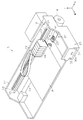
- FIG. 1 is a perspective view of an ink jet printer according to a first embodiment.
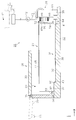
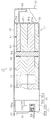
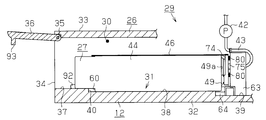
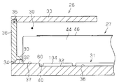
- FIG. 2 is a partially omitted cross-sectional view of a housing in the printer of FIG. 1.
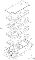
- FIG. 2 is an exploded perspective view of a waste ink tank according to the first embodiment.
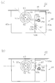
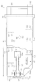
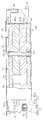
- FIG. 4 is a partially broken plan view of the waste ink tank of FIG. 3.
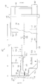
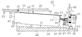
- FIG. 4 is a partially broken front view of the waste ink tank of FIG. 3.
- 3A is a rear side view of the waste ink tank of FIG. 3
- FIG. 4B is a rear side view of the waste ink tank of the comparative example.
- the disassembled perspective view of a tube support mechanism is a partially omitted cross-sectional view of a housing in the printer of FIG. 1.
- FIG. 2 is an exploded perspective view of a waste ink tank according to the first embodiment.
- FIG. 4 is a partially broken plan view of the waste ink tank of FIG. 3.
- FIG. 4 is a partially broken
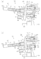
- FIG. 3 is a partially omitted cross-sectional view illustrating a state in a storage chamber when a waste ink tank is mounted.
- FIG. 3 is a partially omitted cross-sectional view illustrating a state in a storage chamber when a waste ink tank is mounted. The partially broken plan view of the waste ink tank of 2nd Embodiment.
- FIG. 6 is a plan view of a partially omitted waste ink tank.
- FIG. 6 is a plan view of a partially omitted waste ink tank.
- FIG. 6 is a plan view of a partially omitted waste ink tank.
- FIG. 6 is a plan view of a partially omitted waste ink tank.
- FIG. 10 is a partially omitted cross-sectional view of a housing that houses a waste ink tank according to a modification.
- (A) and (b) are some omission cross sections of the waste ink tank of a modification.
- (A) and (b) are the top views of the waste ink tank of a modification
- (c) is a front view of the waste ink tank of a modification.
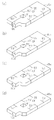
- (A)-(d) is a perspective view of the ink absorber of a modification. The partially broken front view of the waste ink tank of a modification.
- an ink jet printer 11 as a liquid ejecting apparatus includes a frame 12 having a rectangular shape in plan view.
- a platen 13 extends in the left-right direction in the frame 12, and the recording paper P is fed from the rear side to the front side by a paper feed mechanism having a paper feed motor 14 on the platen 13.
- a guide shaft 15 extending in parallel with the longitudinal direction (left-right direction) of the platen 13 is installed above the platen 13 in the frame 12.
- the carriage 16 is supported on the guide shaft 15 so as to be capable of reciprocating along the axial direction (left-right direction) of the guide shaft 15.
- a driving pulley 17 and a driven pulley 18 are rotatably supported at positions corresponding to both end portions of the guide shaft 15 on the rear surface in the frame 12.
- a carriage motor 19 serving as a drive source for reciprocating the carriage 16 is connected to the drive pulley 17, and a timing belt 20 for fixing and supporting the carriage 16 is hung between the pulleys 17 and 18. Therefore, the carriage 16 moves in the left-right direction via the timing belt 20 while being guided by the guide shaft 15 by driving the carriage motor 19.
- a recording head 21 as a liquid ejecting head is provided on the lower surface of the carriage 16.
- a plurality (five in this embodiment) of ink cartridges 23 for detachably mounting ink as liquid to the recording head 21 are mounted on the carriage 16 in a detachable manner.
- Each of these ink cartridges 23 individually corresponds to a plurality of nozzle opening rows (not shown) formed on a nozzle forming surface 21 a (see FIG. 2) formed on the lower surface of the recording head 21.
- the ink is individually supplied to the corresponding nozzle row via the formed ink flow path (not shown).
- the carriage 16 is positioned at one end portion in the frame 12 (right end portion in FIG. 1), that is, a non-printing area where the recording paper P does not reach when the printer 11 is powered off or when the recording head 21 is maintained.
- a home position HP serving as a maintenance position is provided.
- a maintenance unit 24 that performs various maintenance operations is provided so that the ejection of ink from the recording head 21 to the recording paper P is well maintained.
- the maintenance unit 24 includes a cap 25 having a substantially rectangular box shape corresponding to the lower surface (nozzle forming surface) of the recording head 21 and a lifting device (not shown) for moving the cap 25 up and down.
- a cap 25 having a substantially rectangular box shape corresponding to the lower surface (nozzle forming surface) of the recording head 21 and a lifting device (not shown) for moving the cap 25 up and down.
- the cap 25 is raised based on the driving of the lifting device (not shown) in a state where the carriage 16 is moved to the home position HP, the cap 25 is placed on the nozzle forming surface 21a that is the lower surface of the recording head 21. Abut in a state of surrounding the nozzle row.
- a housing 26 having a rectangular parallelepiped shape along the front-rear direction is formed at a position below the home position HP at one end portion (right end portion in FIG. 1) in the frame 12.
- a storage chamber 30 for storing a waste liquid recovery system 29 having a waste ink tank 27 as a waste liquid recovery body and a tube support mechanism 28 as a liquid flow path forming device.
- a mounting position 31 of the waste ink tank 27 is set at the lower part.
- the height of the storage chamber 30 (the distance between the bottom wall 32 and the upper wall 33) allows the waste ink tank 27 to tilt in the storage chamber 30. The height of the waste ink tank 27 is sufficiently higher.
- a rectangular attachment / detachment port 34 is formed on the front side of the housing 26 for allowing the waste ink tank 27 to pass through the attachment / detachment position 31.
- the detachable opening 34 is provided with an open / close door 36 whose upper ends are rotatably supported by a pair of shaft portions 35 provided on both sides of the upper edge of the detachable opening 34. Then, the opening / closing door 36 is closed and opened by a solid line in FIG. 2 and an open position shown by a two-dot chain line when a knob 36a formed on the front surface of the opening / closing door 36 is gripped and opened and closed. Open and close between.
- a front step surface 37, a middle step surface 38, and a rear step surface 39 are stepped on the upper surface of the bottom wall 32 in order from the front to the rear in the front-rear direction. It is formed as follows.
- the front step surface 37 has the same height as the portion of the bottom wall 32 that defines the attachment / detachment port 34, and the intermediate step surface 38 is located between the rear end of the front step surface 37 and the front end of the middle step surface 38 rather than the front step surface 37.
- a locking step portion 40 as a locking portion that lowers the side extends in the left-right direction.
- the length in the front-rear direction of the middle step surface 38 is slightly shorter than the length in the front-rear direction of the waste ink tank 27, and the entire region of the middle step surface 38 and the rear half region of the front step surface 37 define the mounting position 31 of the waste ink tank 27. It is composed.
- the rear stage surface 39 is formed slightly lower than the middle stage surface 38 via the stepped portion 41, and the tube support mechanism 28 is installed on the rear stage surface 39, and the tube support mechanism 28 is moved to the cap 25 as the suction pump 42 is driven.
- a flexible tube 43 for discharging waste liquid, that is, ink forcedly sucked as waste ink from the inside into the waste ink tank 27 is supported.
- waste liquid recovery system 29 provided with the waste ink tank 27 and the tube support mechanism 28 and provided in the printer 11 will be described.
- the waste ink tank 27 will be described.
- the waste ink tank 27 includes a synthetic resin container member 44 having a bottomed box shape with an open top, a non-woven fabric formed in a shape corresponding to the opening shape of the container member 44, A plurality of (four in the present embodiment) ink absorbing materials made of felt or the like, that is, the waste liquid absorbing materials 45a to 45d, and the gas-liquid formed in the shape corresponding to the opening shape of the container member 44. And a film member 46 as an impermeable sealing member.
- the internal space of the container member 44 is a storage space 47, and the ink absorbing materials 45a to 45d are stored in a stacked state in the storage space 47.
- the film member 46 is adhered to the container member 44 so as to cover the upper end opening 48 of the container member 44 in the state in which the respective ink absorbing materials 45a to 45d are accommodated.
- the upper end opening 48 is sealed.
- the film member 46 has an air communication hole 90 formed at one location on the front end side of the center portion.
- ribs 52 having a thin plate shape are formed. It is formed along the vertical direction.
- FIG. 3 shows only one rib 52 on the rear side wall 49 and three ribs 52 on the right side wall 51.
- a cut 53 is formed in the outer edge of each ink absorbing material 45a to 45d so as to correspond to the position of each rib 52.
- a columnar column 54 is erected at a substantially central position of the inner bottom surface of the container member 44, and the column 54 can be fitted to a substantially central position of each ink absorbing material 45 so as to correspond to the column 54.
- a circular hole 55 as a fitting hole is formed penetratingly.
- Each of the ink absorbing materials 45a to 45d is laminated in the accommodation space 47 of the container member 44 so that the corresponding ribs 52 enter the respective notches 53 and the columns 54 are inserted into the holes 55. Is housed in.
- the locking of the ink absorbing materials 45a to 45d to the column 54 restricts the movement of the ink absorbing materials 45a to 45d to the inner surface side of the side walls in the container member 44.
- a recessed portion 56 is formed in a corner portion on the left side of the rear portion of the container member 44.
- the rear side wall 49 is separated into a main rear side wall 49a positioned relatively on the rear side and a sub rear side wall 49b positioned relatively on the front side, and the left side wall 50 is relatively positioned on the left side.
- the left side wall 50 is relatively positioned on the left side.
- a reinforcing rib 56a having a substantially triangular plate shape in plan view is provided between the auxiliary rear side wall 49b and the auxiliary left side wall 50b at the upper part of the recessed portion 56.
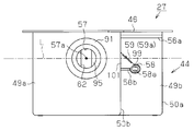
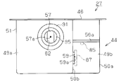
- a connection port 57 as a circular opening is formed through the main rear side wall 49a, and a cylindrical tube portion 58 having a horizontally long cross section (see FIG. 6A) is provided rearward from the sub rear side wall 49b.
- the long hole 58a for projecting toward and aligning the cylindrical portion 58 constitutes a positioning means.
- the cylinder part 58 is connected with the sub left side wall 50b by the reinforcing rib 58b.
- the diameter of the inner peripheral surface of the connection port 57 gradually decreases toward the back, that is, the front.
- connection port 57 guides the member with the inside of the connection port 57 facing the back center. It has the function to do.
- annular seal portion 91 is formed around the connection port 57 so as to surround the connection port 57, and the end surface of the seal portion 91 forms a smooth flat surface parallel to the main rear side wall 49a.
- connection terminal 59 is attached as a recovery body side connection terminal of a circuit board (not shown) that stores various information relating to the capacity of the waste ink tank 27 and the like.
- a connection terminal 87 is made with respect to the contact surface of a connection terminal 87 (see FIGS. 7 to 9) as a device-side connection terminal provided in the tube support mechanism 28 of the printer 11.
- connection terminals 59 and 87 are appropriately connected as described above, for example, between the circuit board of the waste ink tank 27 and the control device (not shown) of the printer 11, for example, the waste ink tank 27.
- Various types of information related to waste ink such as information on the start date of use, the number of times cleaning is performed, and the accumulated amount of waste ink discharged, are exchanged.
- connection terminal 59 is not connected to the main rear side wall 49 a that is the same as the connection port 57 in the waste ink tank 27, but to the sub left side wall 50 b that intersects at right angles thereto. In the vertical direction, it is provided at a position below the connection port 57 and the cylindrical portion 58 (long hole 58a). That is, the connection terminal 59 is not located on the upper side of the container member 44 near the upper end opening 48 that easily deforms when stress is applied, but on the lower side because it is close to the bottom and is relatively rigid and difficult to deform. The position is provided at a position that is not directly below the connection port 57.
- connection terminal 59 extends in a radial direction in which the contact surface 59a is obliquely downward to the left from the center 57a of the connection port 57 when the main rear side wall 49a is viewed from the front. It is provided at a position below the sub left side wall 50b so as to be non-perpendicular to the straight line L. That is, the contact surface 59a of the connection terminal 59 extends along the vertical plane and in the front-rear direction. As shown in FIG. 5, the connection terminal 59 is provided in the waste ink tank 27 at a position between the connection port 57 and the cylindrical portion 58 (long hole 58a) in the front-rear direction.
- a locked stepped portion 60 is formed on the bottom wall 32 of the housing 26 so as to extend in the left-right direction at a position slightly closer to the rear end than the front end of the outer bottom surface of the container member 44.
- the locked step portion 60 is an engaging portion that can engage with the locking step portion 40 in the front-rear direction.
- a projecting portion 92 having a rectangular parallelepiped shape protrudes forward from the left end position of the lower front end of the container member 44.
- a protrusion 93 is formed on the rear surface side of the opening / closing door 36.
- the protrusion 93 is formed with respect to the convex portion 92 of the waste ink tank 27.
- the open / close door 36 is in the open position, it is in a non-restricted state separated from the restricted position.
- a grip portion 94 that grips the waste ink tank 27 when the user attaches or detaches has a substantially L-shaped cross section with the tip portion bent downward. Is formed. That is, the grip portion 94 is gripped by the fingertip of the user's hand by forming a concave portion so that the lower portion of the front surface of the container member 44 in the vertical direction extends toward the inside (in this case, the rear side) of the container member 44. It is formed in an easy shape. And the convex part 92 mentioned above is formed in the left side among the right-and-left both sides of the recessed part.
- the lowermost first ink absorbing material 45a and the uppermost fourth ink absorbing material 45d are formed in the same form with the same thickness
- the second ink absorbing material 45b that is the second from the bottom and the third ink absorbing material 45c that is the third from the bottom are formed to have the same thickness.
- the second ink absorbing material 45b and the third ink absorbing material 45c each include a through hole 61 having a square shape at each position slightly rearward of the center, and the third ink absorbing material 45c extends from the rear edge to the through hole.
- a notch groove 62 formed in the front-rear direction as a contact portion and a guide portion having a predetermined width is provided.
- the fourth ink absorbing material 45d and the second ink absorbing material 45b do not have a cut groove at a position corresponding to the cut groove 62 of the third ink absorbing material 45c.
- the cut groove 62 of the third ink absorbing material 45c is closed from both the upper and lower sides.
- the cut groove 62 has an arrangement of a pair of ribs 52 whose groove width at the rear end is formed so as to sandwich the connection port 57 from both the left and right sides on the inner surface of the rear side wall 49 of the container member 44. While the groove width is set to be wide corresponding to the interval, the groove width on the front end side on the through hole 61 side is formed to be narrower than the groove width on the rear end portion. And the part which connects this narrow front-end side groove part and the wide rear-end groove part has the taper part 95 which spreads to the rear end side.
- the tube support mechanism 28 has a substantially channel shape in plan view in which the front ends of the left and right side walls forming a rectangular shape are connected by a front wall having the same rectangular shape.
- a base portion 63 is provided.
- a horizontal plate portion 64 having a rectangular plate shape extends forward from a lower portion of the front end of the base portion 63, and a pair of left and right screw holes 65 are formed through the horizontal plate portion 64.
- the base portion 63 is fixed onto the rear surface 39 of the bottom wall 32 of the housing 26 by screwing a set screw 66 into each screw hole 65 of the horizontal plate portion 64.
- a plurality of (three in this embodiment) through holes 67, 68, 69 are aligned in the vertical direction on the front wall of the base portion 63.
- the central through hole 68 is a waste mounted at the mounting position 31 in the storage chamber 30 when the base portion 63 is fixed on the rear stage surface 39 of the bottom wall 32 of the housing 26. It is formed at a height that is coaxial with the connection port 57 of the ink tank 27.
- An inward flange portion 70 (see FIGS. 8A and 8B) is formed at a midway position in the axial direction of the inner peripheral surface of each of the upper through hole 67 and the lower through hole 69.
- a tube stopper 71 having a substantially U shape capable of sandwiching and supporting the flexible tube 43 is formed at a substantially central portion of the upper end portion of the front wall of the base portion 63.
- a support member 72 for supporting the flexible tube 43 in a straight line is assembled on the front surface side of the base portion 63.
- the support member 72 is a resin molded product having a predetermined length of rigidity in the front-rear direction formed mainly of a cylindrical body 73 that can be inserted into and removed from the connection port 57 of the waste ink tank 27.
- a rectangular plate-shaped flange portion 74 is integrally formed at a position slightly behind the axially intermediate position 73, that is, a position closer to the base end side.
- the base end side cylindrical part 75 as a 2nd support part protrudes behind the collar part 74 of the cylindrical body 73, and the outer diameter of the base end side cylindrical part 75 is a base
- the inner diameter of the proximal cylindrical portion 75 is smaller than the diameter of the 63 central through hole 68 and is a diameter through which the flexible tube 43 can be inserted.
- a circular pedestal portion 96 having a diameter slightly larger than the outer diameter of the seal portion 91 of the waste ink tank 27 is formed on the front side of the collar portion 74 so as to be coaxial with the cylindrical body 73.
- a cylindrical discharge portion 97 formed so as to protrude forward from the circular pedestal portion 96 of the flange portion 74 of the cylindrical body 73 is a case where the waste ink tank 27 is mounted at the mounting position 31.
- it is inserted into the connection port 57 while supporting the downstream end side of the flexible tube 43.
- the base end side portion connected to the circular pedestal portion 96 is a fitting cylinder portion 98 having the same inner diameter and outer diameter at the inner back portion of the connection port 57 of the waste ink tank 27.
- the predetermined length portion on the front side, that is, the front end side of the fitting cylinder portion 98 has a slightly smaller outer diameter than the left and right width dimension of the cut groove 62 of the third ink absorbing material 45c accommodated in the waste ink tank 27.
- it is formed to have a length that is substantially the same as the distance from the rear edge of the third ink absorber 45 c to the approximate center of the through hole 61.
- this predetermined length part remove excluding the front end side cylindrical part 76 as a relatively short 1st support part which makes a cylindrical shape in order to internally fit the front end used as the downstream end of the flexible tube 43,
- a relatively long cylindrical portion from the distal end side cylindrical portion 76 to the rear fitting cylindrical portion 98 is a non-cylindrical portion 77 as a second support portion in which about half of the peripheral wall is cut out.
- pinching claws (fastening portions) 78 that are paired with each other at a plurality of locations (three locations in the present embodiment) in the axial direction of the cylindrical body 73 are opposed to the opposing pinching claws 78. Are protruded in such a manner that the interval is slightly smaller than the outer diameter of the flexible tube 43.
- the support member 72 is inserted from the proximal-side opening of the proximal-side tubular portion 75 in a state where the proximal-side tubular portion 75 of the tubular body 73 is loosely inserted into the central through hole 68 of the base portion 63.
- a predetermined length portion on the distal end side including the distal end, that is, the downstream end, of the flexible tube 43 is supported by the distal tubular portion 76 and the non-cylindrical portion 77. That is, since the inner diameter of the distal end side cylindrical portion 76 of the cylindrical body 73 is equal to the outer diameter of the flexible tube 43, the distal end of the flexible tube 43 is supported in a fitted state, and is non-cylindrical.
- the portion 77 is fastened so that a plurality of locations (three locations in the present embodiment) that are continuous from the distal end to the proximal end side of the flexible tube 43 are sandwiched from the side by the respective claws 78. Therefore, the cylindrical body 73 of the support member 72 supports the predetermined length portion on the distal end side of the flexible tube 43 so as to extend along the direction in which the distal end of the flexible tube 43 is directed.
- the discharge portion 97 of the cylindrical body 73 in the support member 72 that supports the flexible tube 43 as described above enters the container member 44 from the connection port 57 of the waste ink tank 27 as shown by a two-dot chain line in FIG.
- the waste ink is discharged from the front end opening 76a of the front end side cylindrical portion 76 of the cylindrical body 73 into the through hole 61 formed in the second ink absorbing material 45b and the third ink absorbing material 45c. Therefore, in this respect, in the present embodiment, the tip opening 76a constitutes a discharge port for discharging the waste ink.
- the discharge portion 97 of the cylindrical body 73 when the discharge portion 97 of the cylindrical body 73 is inserted into the container member 44 from the connection port 57 of the waste ink tank 27, the discharge portion 97 serves as a discharge port.
- the distance Y between the tip opening 76a and the air communication hole 90 is longer than the distance X between the tip opening 76a and the connection port 57.
- the waste ink discharged from the front end opening 76a is absorbed by the ink absorbing materials 45a to 45d, penetrates and diffuses through the ink absorbing materials 45a to 45d, and then the ink solvent is vaporized.
- the member 46 is evaporated from the atmosphere communication hole 90 to the outside.
- a long hole 58a of the cylindrical portion 58 of the waste ink tank 27 is formed on the left edge of the front surface of the flange portion 74 of the support member 72 as shown in FIG. 3, refer to FIG. 6 (a) and FIG. 6 (b)), an alignment pin 85 as a mating member that can be inserted and removed is projected forward.
- a vertical plate portion 86 having a rectangular plate shape is formed to project forward from a position below the pin 85 on the left side edge of the front surface of the flange portion 74.
- a device side connection terminal 87 corresponding to the connection terminal 59 provided on the sub left side wall 50b of the waste ink tank 27 is attached to the right side surface of the vertical plate portion 86.
- the connection terminal 87 is connected via a harness (not shown). Connected to a control device (not shown) of the printer 11.
- the rear surface of the flange portion 74 of the support member 72 can be inserted into the upper through-hole 67 and the lower through-hole 69 of the base portion 63 from two locations, the upper side and the lower side of the base end side cylindrical portion 75.
- a pair of cylindrical portions 79 formed in the above are projected in parallel toward the rear. Each cylindrical portion 79 is inserted into the corresponding upper through-hole 67 and lower through-hole 69 of the base portion 63 with the coil spring 80 functioning as a biasing means penetrating each peripheral surface.
- the front end of the coil spring 80 abuts on the rear surface of the flange portion 74 of the support member 72, and the rear end is provided in the middle of each inner peripheral surface of the upper through hole 67 and the lower through hole 69.
- the flange portion 70 abuts.
- a screw hole (not shown) is formed in the tip surface of each cylindrical portion 79.
- a rectangular assembly plate 81 for assembling the support member 72 to the base unit 63 is disposed on the rear surface side of the base unit 63.
- the assembly plate 81 can be brought into contact with the rear surface of the front wall in a state of being arranged between the left and right side walls of the base portion 63 having a substantially channel shape in plan view.
- a through hole 82 corresponding to the hole 68 is formed.
- Screw insertion holes 83 are formed at two locations corresponding to the upper through hole 67 and the lower through hole 69 of the base portion 63 on the upper side and the lower side of the through hole 82 in the assembly plate 81.
- the assembly plate 81 is a set screw that is inserted into the screw insertion hole 83 with respect to each columnar portion 79 of the support member 72 that protrudes backward from the respective through holes 67 and 69 of the base portion 63. 84 is screwed.
- the base portion 63 of the tube support mechanism 28 is the rear stage surface 39 in the storage chamber 30. It is fixed on top with a set screw 66. Then, after the distal end, that is, the downstream end of the flexible tube 43 having the base end, that is, the upstream end connected to the cap 25 is inserted from the rear side into the through hole 82 of the assembly plate 81, the central through hole 68 of the base portion 63. Also, it is inserted from the rear side and further pulled out to some extent from its central through hole 68.
- the tip of the flexible tube 43 drawn forward from the central through hole 68 of the base portion 63 is inserted into the cylindrical body 73 of the support member 72 before being assembled to the base portion 63.
- the distal end of the flexible tube 43 is inserted into the proximal end side cylindrical portion 75 of the cylindrical body 73, and the distal end of the inserted flexible tube 43 is further inserted into the distal end side cylindrical portion of the cylindrical body 73.
- the non-cylindrical part 77 before 76 is once pulled out.
- the predetermined length portion on the distal end side of the flexible tube 43 is slack enough to be easily gripped outside the non-cylindrical portion 77, and in this state, the distal end of the flexible tube 43 is connected to the cylindrical body.
- 73 is inserted into the distal end side tubular portion 76 from the rear side, that is, the proximal end side.
- the distal end of the flexible tube 43 is aligned with the distal end of the distal tubular portion 76 of the tubular body 73 in the front-rear direction, and is fitted and supported in a stable state by the distal tubular portion 76.
- the proximal end side of the flexible tube 43 is pulled in a direction to be pulled out from the proximal end side cylindrical portion 75 of the cylindrical body 73, and the flexible tube 43 is formed outside the non-cylindrical portion 77. Try to eliminate the slack part. Then, the predetermined length portion on the distal end side of the flexible tube 43 in which the slackness is almost eliminated is sequentially pressed against the inner surface of the non-cylindrical portion 77 from the distal end side, so that the nail 78 between the opposing claws 78 is opposed to each other. Push in. Then, the flexible tube 43 is stably supported by the pinching claws 78 so that a predetermined length portion on the distal end side thereof extends substantially linearly along the non-cylindrical portion 77.
- the support member 72 in a state of supporting the flexible tube 43 is assembled to the base portion 63. That is, the base end side cylindrical portion 75 of the cylindrical body 73 is loosely inserted into the central through hole 68 of the base portion 63 which is in a state where the base end side of the flexible tube 43 is inserted at that time, and the base portion 63.
- Each cylindrical portion 79 of the support member 72 is inserted into the upper through hole 67 and the lower through hole 69. In this case, a coil spring 80 is inserted in advance with respect to each cylindrical portion 79.
- each cylindrical portion 79 is sandwiched between the rear surface of the flange portion 74 and the flange portions 70 in the upper and lower through-holes 67 and 69 and slightly contracted.
- the tips of the portions 79 protrude rearward from the corresponding through holes 67 and 69. Therefore, the assembly plate 81 is brought into contact with the tip of each cylindrical portion 79 protruding from each through hole 67, 69 while aligning the screw insertion hole 83, and is screwed by the set screw 84.
- the base end side portion of the flexible tube 43 drawn rearward from the through hole 82 of the assembly plate 81 is fixed by a tube stopper 71 provided on the upper portion of the base body 63. Thereby, the support operation
- the tube support mechanism 28 supports the flexible tube 43 in a state in which the flexible ink tube 43 is directed to the front side where the waste ink tank 27 is mounted, and the home. It is installed at a position below the cap 25 at the position HP. In the installed state, the coil spring 80 penetrating each cylindrical portion 79 of the support member 72 maintains a slightly contracted state, and the accumulated pressure presses the flange portion 74 toward the front side. 72 is held movably in the front-rear direction with the cylindrical body 73 oriented forward.
- the support member 72 of the tube support mechanism 28 is in a pressure accumulation state in which the coil spring 80 penetrating each columnar portion 79 is slightly contracted, and is urged forward by the urging force of the coil spring 80. It is in. Therefore, when a pressing force is applied from the front side to the rear side with respect to the collar portion 74 of the support member 72, the collar portion 74 is retracted rearward due to the pressing force. As shown in b), the support member 72 moves backward while further contracting the coil spring 80 while supporting the flexible tube 43 together with the assembly plate 81.
- the support member 72 of the tube support mechanism 28 has a cylindrical portion 79 projecting rearward from the proximal end side cylindrical portion 75 and the flange portion 74 of the cylindrical body 73. It is loosely inserted in the radial direction with respect to 69. Therefore, when an external force is applied to the cylindrical body 73 of the support member 72, in particular, from the direction intersecting the axial direction of the cylindrical body 73, the distal side cylindrical portion 76 is supported by receiving the external force.
- the member 72 swings around a contact portion with the flange portion 70 in the cylindrical portion 79 on the proximal end side.
- the support member 72 when an external force is applied from the lower side to the upper side with respect to the distal end side cylindrical portion 76 of the cylindrical body 73, the support member 72 is positioned at the distal end of the cylindrical body 73 as shown in FIG. The side cylindrical portion 76 is swung so as to move upward.
- the support member 72 when an external force is applied from the upper side to the lower side with respect to the distal end side cylindrical portion 76 of the cylindrical body 73, the support member 72 is connected to the distal end of the cylindrical body 73 as shown in FIG. The side cylindrical portion 76 is swung so as to move downward.
- the support member 72 moves the distal end side cylindrical portion 76 of the cylindrical body 73 left and right. Swing to move in the direction.
- the support member 72 that supports the flexible tube 43 in the tube support mechanism 28 has a configuration in which the distal end side is swingable with the proximal end side as a fulcrum.
- the support member 72 in the tube support mechanism 28 is inserted into the connection port 57 of the main rear side wall 49 a of the waste ink tank 27 before the entire waste ink tank 27 completely enters the storage chamber 30.
- the cylindrical part 76 at the front end side of the cylindrical body 73 is inserted.
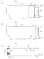
- the waste ink tank 27 is usually configured such that the grip 94 at the front end of the waste ink tank 27 is used by the user of the printer 11. And is moved in the mounting direction by the user's manual operation. Therefore, in the waste ink tank 27 in which the grip portion 94 is gripped by the user, the container member 44 is rarely in the horizontal state before the entire tank 27 enters the storage chamber 30. As shown in FIG. 10, the posture of the container member 44 is often inclined such that the rear end portion is lower than the front end portion.
- the distal end side of the cylindrical body 73 extends to the back of the connection port 57 of the waste ink tank 27 that moves in the mounting direction in an inclined posture. It becomes difficult to insert the cylindrical portion 76.
- the tube support mechanism 28 of the present embodiment is configured such that the support member 72 can swing freely on the distal end side with the base end side as a fulcrum. Therefore, when the support member 72 is inserted into the connection port 57 of the waste ink tank 27 that has been moved in a state where the distal end side cylindrical portion 76 of the cylindrical body 73 is inclined, the support member 72 corresponds to the inclination. Swing the tip side. Therefore, the distal end side cylindrical portion 76 is inserted into the connection port 57 of the waste ink tank 27 without trouble.
- the support member 72 of the tube support mechanism 28 may be displaced from the center 57 a of the connection port 57 when the distal end side cylindrical portion 76 is inserted into the connection port 57 of the waste ink tank 27.
- the inner peripheral surface of the connection port 57 in the waste ink tank 27 of the present embodiment is a tapered surface whose diameter decreases toward the back in the connection port 57
- the cylindrical body 73 of the support member 72 is As it is inserted into the connection port 57, it is slidably guided toward the center 57a of the connection port 57.
- the cylindrical body 73 of the support member 72 is smoothly inserted into the cut groove 62 of the third ink absorbing material 45c.
- the rear end portion of the cut groove 62 on the connection port 57 side has a tapered portion 95 that gradually becomes narrower toward the front end portion.
- the groove width at the front end side of the taper portion 95 is slightly wider than the outer diameter of the discharge portion 97.
- the thickness of the third ink absorbing material 45 c in which the cut groove 62 is formed is slightly larger than the outer diameter of the discharge portion 97.
- the groove 62 is slidably guided in a preset direction, that is, a direction toward the through hole 61 by the lower surface of the fourth ink absorbing material 45d and the upper surface of the second ink absorbing material 45b that block the groove 62 from the upper and lower sides.
- the rear side wall 49 (specifically, the end surface of the seal portion 91) of the waste ink tank 27
- the flange portion 74 (specifically, the circular pedestal portion 96) of the support member 72 is in contact with the cylindrical body 73 of the support member 72, and the front end side cylindrical portion 76 is formed in the third ink absorbing material 45c. It reaches the position of the hole 61.
- connection port 57 is closed in a sealed state by the circular pedestal portion 96.
- the circular pedestal portion 96 functions as a closing portion that closes the connection port 57 by contacting the seal portion 91.
- the sealing portion 91 is formed in an annular shape surrounding the connection port 57, the end surface formed on the smooth flat surface comes into surface contact with the opposing surface of the smooth flat surface of the circular pedestal portion 96, so that the sealing function is achieved. Easy to secure.
- a pin 85 protruding from the flange portion 74 of the support member 72 is provided. Is inserted into the elongated hole 58a of the cylindrical portion 58 provided in the auxiliary rear side wall 49b of the waste ink tank 27, thereby positioning the waste ink tank 27 in the vertical direction, the horizontal direction, and the rotational direction with respect to the mounting position 31.
- the pin 85 and the long hole 58a function as a holding unit that holds the waste ink tank 27 in a positioning state so as to restrict movement in the vertical direction, the horizontal direction, and the rotation direction at the mounting position 31.
- the waste ink tank 27 is directed toward the mounting position 31 of the printer 11 while rotating around the axis of the discharge portion 97 of the cylindrical body 73 inserted into the connection port 57.
- the connection terminal 59 on the side of the waste ink tank 27 and the connection terminal 87 of the printer 11 may be connected to each other in the rotational direction.
- the contact surface 59a of the connection terminal 59 of the waste ink tank 27 is provided so as to be perpendicular to the straight line L extending in the radial direction from the center 57a of the connection port 57. If the waste ink tank 27 rotates, the contact surfaces of the connection terminals 59 and 87 may be slid and damaged so as to pass each other along the rotation direction, resulting in poor contact.
- the contact surface 59a of the connection terminal 59 of the waste ink tank 27 is non-perpendicular to the straight line L extending in the radial direction from the center 57a of the connection port 57. Therefore, when the waste ink tank 27 is rotated, the contact surfaces of the connection terminals 59 and 87 are not slidably contacted with each other along the rotation direction. That is, in FIG. 6A, when the waste ink tank 27 rotates in the clockwise direction, the connection terminal 59 of the waste ink tank 27 moves so that the contact surface 59a is separated from the connection terminal 87 of the printer 11. Conversely, in FIG. 6A, when the waste ink tank 27 rotates counterclockwise, the connection terminal 59 of the waste ink tank 27 moves in a direction in which the contact surface 59 a is pressed against the connection terminal 87 of the printer 11.
- the long hole 58a as the positioning means functions as a contact portion for restricting the rotation of the waste ink tank 27 by the inner peripheral surface 99 defining the long hole 58a contacting the pin 85.
- the long hole 58a is formed in such a manner that the upper portion of the inner peripheral surface 99 that defines the long hole 58a comes into contact with the pin 85, whereby the connection terminal 59 of the waste ink tank 27 is separated from the connection terminal 87 of the printer 11. While restricting the clockwise rotation, the lower portion of the inner peripheral surface 99 abuts against the pin 85, thereby restricting the waste ink tank 27 from rotating in the opposite clockwise direction.
- the waste ink tank 27 is mounted by being moved toward the mounting position 31 of the printer 11 while rotating around the axis of the discharge portion 97 of the cylindrical body 73 inserted into the connection port 57.
- the contact surface 59a of the connection terminal 59 is not slidably contacted with the connection terminal 87 of the printer 11 so that the contact surfaces pass along the rotation direction.
- the waste ink tank 27 has passed the mounting position 31 in the storage chamber 30 in the mounting direction. That is, the locked step portion 60 of the waste ink tank 27 is formed in a shape that does not engage with the locking step portion 40 on the printer 11 side when moving in the mounting direction.
- the waste ink tank 27 is accumulated. Since the flange portion 74 of the support member 72 is moved forward by the biasing force of the coil spring 80, the flange portion 74 is pressed forward, that is, in the direction of taking out the waste ink tank 27. That is, the collar portion 74 of the support member 72 functions as a pressing means that uses the biasing force of the coil spring 80 as a pressing force, and presses the waste ink tank 27 in the take-out direction using the rear side wall 49 of the container member 44 as a pressed portion. .
- the waste ink tank 27 slides forward on the middle step surface 38 of the attachment position 31, and the locked step portion 60 of the container member 44 is attached to the attachment position 31 as shown in FIG.
- the locking step 40 is locked. That is, when the waste ink tank 27 moves in the mounting direction opposite to the take-out direction with respect to the locked step portion 60 of the container member 44, the locking step portion 40 that cannot be locked is attached to the waste ink tank 27.
- it functions as a locking means that locks from the take-out direction side so as to restrict movement of the waste ink tank 27 in the take-out direction.
- the waste ink tank 27 receives the urging force of the coil spring 80 from the rear via the flange 74 of the support member 72, and the engagement position 31 is engaged with the locked stepped portion 60 on the bottom surface of the container member 44 from the front.
- the stop portion 40 is locked and is positioned at the mounting position 31 in the storage chamber 30 so as not to move in the front-rear direction.
- the coil spring 80 as the urging means and the locking step portion 40 as the locking means function as a holding means for holding the waste ink tank 27 at the mounting position 31 in a positioned state.
- the opening / closing door 36 of the opening / closing port 34 is in the closed position, and the protrusion 93 on the back surface side of the opening / closing door 36 is in the restriction position close to the convex portion 92 at the front end of the waste ink tank 27. . Therefore, even when the printer 11 is carried around and the waste ink tank 27 is displaced upward due to an external impact, the projection 93 of the open / close door 36 abuts on the projection 92 of the waste ink tank 27, Such upward displacement is restricted. Therefore, the engaged state of the locked step portion 60 of the waste ink tank 27 with respect to the locking step portion 40 provided at the mounting position 31 of the printer 11 is not released.
- the leading end opening 76a of the discharge portion 97 reaches the through hole 61 of the third ink absorbing material 45c from the connection port 57 of the waste ink tank 27.
- a through hole 61 of the second ink absorbing material 45b is disposed below the through hole 61 of the third ink absorbing material 45c, and the fourth ink absorbing material 45d and the second ink absorbing material 45d are closed so as to close the upper and lower sides of the two through holes 61.
- a first ink absorbing material 45a is disposed. And most of the waste ink discharged into the through hole 61 is gradually absorbed from the upper surface of the first ink absorbing material 45a located at the lower part of the through hole 61 into the entire first ink absorbing material 45a.
- the ink absorbing materials 45a to 45d the vicinity of the through hole 61 through which the waste ink is discharged from the front end opening 76a of the discharge portion 97 is the portion where the amount of absorbed waste ink is the largest.
- the fourth ink absorbing material 45d into which the waste ink discharged from the front end opening 76a of the discharging portion 97 penetrates most slowly is the portion with the smallest ink absorption amount.
- the waste ink absorbed by the ink absorbing materials 45a to 45d has a property that it easily permeates and diffuses from a location where the amount of absorption is large to a location where it is small.
- the atmospheric communication hole 90 formed in the film member 46 that seals the upper end opening 48 of the container member 44 in the waste ink tank 27 of the present embodiment is a position where the formation position is on the front end side of the central portion in the container member 44. Is set to That is, as shown in FIG. 4, the distance Y between the tip opening 76a and the atmosphere communication hole 90 is longer than the distance X between the tip opening 76a and the connection port 57 of the discharge portion 97 that discharges waste ink. It has become.
- the air communication hole 90 is located above the upper surface of the fourth ink absorbing material 45d located at the uppermost position among the ink absorbing materials 45a to 45d.
- the waste ink penetrates to a position away from the front end opening 76a in the front-rear direction and then penetrates to the uppermost absorbent in the vertical direction, that is, the waste ink diffuses throughout the ink absorbents 45a to 45d. Then, it evaporates from the upper surface of the uppermost ink absorbing material 45d.
- the waste ink can permeate a wide range without evaporating from the ink absorbing materials 45a to 45d and clogging the ink absorbing materials 45a to 45d in the permeation process. As a result, a larger amount of waste ink can be discharged. Then, vaporization of the ink solvent of the waste ink is promoted from such a wide diffusion region, and drying of the ink absorbing materials 45a to 45d is promoted. Since the position of the tip opening 76a is a position for discharging waste ink, the distance X may be the distance between the through hole 61 as a waste liquid receiving portion that receives the waste ink and the connection port 57, and the distance Y is the through hole. The distance between 61 and the air communication hole 90 may be used.
- the open / close door 36 of the attachment / detachment port 34 is opened again.
- the protrusion 93 on the back surface side of the open / close door 36 becomes a non-restricted position separated from the restricted position close to the convex portion 92 of the waste ink tank 27, and allows the upward displacement of the waste ink tank 27.
- the user of the printer 11 inserts his / her hand into the insertion / removal port 34 to grip the grip 94 at the front end of the waste ink tank 27 and lift the front end of the waste ink tank 27 upward.
- the locked state of the locking step 40 and the locked step 60 is released. Then, in this state, the urging force of the coil spring 80 acts as a pressing force on the waste ink tank 27 via the flange portion 74 of the support member 72 and acts in the take-out direction, that is, forward. Becomes a force for assisting movement in the take-out direction, and the waste ink tank 27 is easily taken out from the attachment / detachment port 34.
- the discharge portion 97 of the cylindrical body 73 in the support member 72 when the discharge portion 97 of the cylindrical body 73 in the support member 72 is removed from the connection port 57 of the waste ink tank 27, the discharge portion 97 has a tubular portion on the tip side of the fitting tube portion 98.
- the wall surface defining the left and right grooves of the cut groove 62 of the third ink absorbing material 45c, the lower surface of the fourth ink absorbing material 45d that covers the cut groove 62 from both the upper and lower sides, and the upper surface of the second ink absorbing material 45b serve as contact portions.
- the sliding contact is made so as to perform the function of wiping.
- the ink absorbing materials 45a to 45d are swollen by the waste ink absorbed. Therefore, the swollen third ink absorbing material 45c narrows the left and right groove width of the cut groove 62.
- the distance that is, the groove height
- the contact pressure on the discharge portion 97 by the wall surface defining the left and right grooves of the cut groove 62 in the third ink absorbing material 45c, the lower surface of the fourth ink absorbing material 45d, and the upper surface of the second ink absorbing material 45b is also increased.
- the waste ink adhering to the discharge unit 97 is surely wiped off.
- the ink absorbing materials 45a to 45d still have a high absorption capacity, the waste ink adhering to the discharge portion 97 even if the contact pressure is weak, and the wall surface defining the left and right grooves of the cut groove 62
- the ink absorbing materials 45a to 45d are easily absorbed by the lower surface of the fourth ink absorbing material 45d and the upper surface of the second ink absorbing material 45b. Therefore, the waste ink attached when the cylindrical portion of the discharge portion 97 on the front end side of the fitting cylindrical portion 98 is extracted from the connection port 57 of the waste ink tank 27 is in the third ink absorbing material 45c.
- Wiping and removal are performed by the wall surface defining the left and right grooves of the cut groove 62, the lower surface of the fourth ink absorbing material 45d, and the upper surface of the second ink absorbing material 45b.
- the third ink absorbing material 45c in which the cut groove 62 is formed, the fourth ink absorbing material 45d and the second ink absorbing material 45b that block the cut groove 62 of the third ink absorbing material 45c from both the upper and lower sides are wiping members. Function as.
- the flexible tube 43 is a main body of the liquid flow path that guides the waste ink to the waste ink tank 27, and has excellent gas-liquid impermeability but does not have rigidity.
- a flexible tube 43 is linearly supported by the cylindrical body 73 of the rigid support member 72 and is inserted into the connection port 57 of the waste ink tank 27 together with the discharge portion 97 in the cylindrical body 73. .
- the flexible tube 43 can be reliably inserted to a position closer to the center (position of the through hole 61) in the waste ink tank 27 in which the ink absorbing materials 45a to 45d are stacked and accommodated.
- the waste ink tank 27 is movable with respect to the connection port 57 by moving the container member 44 to the rear side in the mounting direction or the front side in the removal direction with respect to the mounting position 31 in the storage chamber 30.
- the discharge portion 97 of the cylindrical body 73 in the support member 72 that supports a predetermined length portion on the downstream end side of the flexible tube 43 is inserted and removed, and the connection port 57 is downstream of the flexible tube 43 supported by the support member 72. Since it is connected to or disconnected from the end, the replacement work of the old and new waste ink tanks 27 can be easily performed.
- connection terminal 59 of the waste ink tank 27 is provided at a lower position where the rigidity is relatively high in the container member 44 having a bottomed box shape, even if stress is applied to the container member 44, The possibility that the position of the connection terminal 59 is displaced can be reduced, and an appropriate connection state with respect to the connection terminal 87 of the printer 11 can be favorably maintained.
- connection port 57 into which the discharge portion 97 is inserted is positioned above the container member 44 from the position where the connection terminal 59 is provided, and waste ink can be stored up to the height position.
- the storage efficiency of waste ink in the container member 44 can be improved.
- connection terminal 59 Since the connection terminal 59 is not located directly below the connection port 57, even if waste ink stored inside from the connection port 57 leaks out in the mounting state with respect to the mounting position 31 of the printer 11, the leakage occurs. It is possible to avoid the possibility that the connection terminal 59 is stained by the waste ink.
- the waste ink tank 27 rotates around the axis of the discharge portion 97 while inserting the discharge portion 97 into the connection port 57.
- the rotation restriction can be achieved by a simple operation of inserting the pin 85 as the counterpart member into the long hole 58a as the positioning means. That is, by adjusting the posture of the waste ink tank 27 so that the pin 85 is inserted into the long hole 58 a, the contact surface 59 a of the connection terminal 59 is connected to the connection position 59 of the waste ink tank 27 with respect to the mounting position 31. It is possible to accurately position and attach to the connection state in proper contact with 87.
- connection portion 59 of the waste ink tank 27 is connected to the connection terminal 87 of the printer 11 because the upper portion of the inner peripheral surface 99 that particularly defines the long hole 58a is in contact with the pin 85. Since the rotation in the separating direction is restricted, it is possible to prevent the waste ink tank 27 from rotating in the direction in which the connection terminals 59 and 87 are in poor contact.
- the inner peripheral surface 99 is provided along the insertion / extraction direction of the discharge portion 97 with respect to the connection port 57 of the waste ink tank 27. Therefore, when the waste ink tank 27 is moved in the mounting direction while the discharge portion 97 is inserted into the connection port 57, the contact state between the inner peripheral surface 99 of the long hole 58a and the pin 85 is maintained. The contact state of the connection terminal 59 of the waste ink tank 27 with respect to the connection terminal 87 of the printer 11 is also maintained, and the contact state of both the connection terminals 59 and 87 at the time of mounting can be appropriately ensured.
- connection terminal 59 since the connection terminal 59 is located on the same side as the projection 92 when viewed from the connection port 57 through which the discharge portion 97 is inserted and removed, the projection 92 is formed on the projection 93 of the door 36. Even in the case of contact, the degree of deformation of the portion of the container member 44 where the connection terminal 59 is provided can be reduced, and the possibility of poor contact with the connection terminal 87 of the printer 11 can be reduced.
- the waste ink tank 27 In a state where the waste ink tank 27 is mounted at the mounting position 31, the waste ink tank 27 is not prepared by positioning the open / close door 36 at the closed position so that the projection 93 serving as a displacement restricting portion is positioned at the restricting position. The movement from the mounting position 31 can be suppressed.
- the waste ink tank 27 is taken out from the mounting position 31 of the printer 11, the waste ink tank is formed by positioning the open / close door 36 at the open position so that the protrusion 93 as the displacement restricting portion is located at the non-regulating position. 27 can be easily taken out.
- the upper end opening 48 of the container member 44 is sealed by a film member 46 as a sealing member, and the ink absorbing material is formed through an air communication hole 90 formed at one location of the film member 46.
- the ink solvent of the waste ink absorbed by 45a to 45d is evaporated to the outside. Therefore, unlike the case where the upper end opening 48 of the container member 44 is opened without being sealed, the solvent component of the waste ink received in the waste ink tank 27 is suppressed from being excessively evaporated and volatilized, Therefore, waste ink residues do not accumulate on the surfaces of the ink absorbing materials 45a to 45d stacked and accommodated.
- the waste ink tank 27 has the absorption capacity of the ink absorbing materials 45a to 45d installed therein. Can be maintained well.
- the atmosphere communication hole 90 is located above the upper surface of the uppermost ink absorbing material 45d in the housing space 47 that is the internal space of the waste ink tank 27 in which the ink absorbing materials 45a to 45d are accommodated. To communicate with the atmosphere. For this reason, even when the waste ink is absorbed to the extent that the ink absorbing materials 45a to 45d saturate the absorption capacity, the possibility that the waste ink leaks out from the atmosphere communication hole 90 can be reduced.
- the waste ink tank is simply attached by adhering the film member 46 to the upper end opening 48 of the container member 44 in which the ink absorbing materials 45a to 45d are installed. 27 can be manufactured.
- the downstream end flow path portion having a predetermined length connected to the downstream end of the flexible tube 43 that discharges waste ink is connected to the connection port 57 together with the support member 72. Therefore, the waste ink can be discharged from the downstream end of the flexible tube 43 to a position closer to the center in the container member 44. As a result, the waste ink is absorbed so as to diffuse into the ink absorbers 45a to 45d, and the waste ink storage efficiency is improved.
- the wall surface defining the left and right grooves is in contact with the discharge portion 97 from both the left and right sides, and the upper surface of the second ink absorbing material 45b third from the top is in contact with the discharge portion 97 from below. That is, these three ink absorbing materials 45b, 45c, and 45d come into contact with the discharge portion 97 so as to be sandwiched from above, below, left, and right directions. Accordingly, the flexible tube 43 exposed at the distal end side cylindrical portion 76 and the non-cylindrical portion 77 of the cylindrical body 73 of the support member 72 and the non-cylindrical portion 77 in a state where the waste ink tank 27 is detached from the printer 11. It is possible to prevent the waste ink from flowing down from this portion (that is, the discharge portion 97) and contaminating the periphery of the connection port 57 and the mounting position 31 of the waste ink tank 27.
- the contact pressure with respect to the discharge portion 97 by the wall surface defining the left and right grooves of the cut groove 62 in the third ink absorbing material 45c, the lower surface of the fourth ink absorbing material 45d, and the upper surface of the second ink absorbing material 45b is also increased.
- the waste ink adhering to the discharge portion 97 can be reliably wiped away.
- the ink absorbers 45a to 45d can be easily absorbed and removed via the upper surface of the ink absorber 45b.
- the upper surface of the second ink absorbing material 45b is in contact with the discharge portion 97 from the lower side in the gravity direction. Therefore, in the discharge portion 97, the waste ink attached to the outer peripheral surface thereof is surely wiped off, and particularly, the attached waste ink travels around the outer peripheral surface of the discharge portion 97 according to gravity, so that the waste ink adheres most. Since the upper surface of the second ink absorbing material 45b is also in reliable contact with the lower surface of the discharge portion 97, which is considered to be the waste ink, the waste ink adhering to the discharge portion 97 pulled out from the connection port 57 is efficiently removed. Can do.
- the ink absorbing materials 45b, 45c, and 45d accommodated in the container member 44 are provided with columns 54 that function as movement restricting portions. The movement toward the inner wall surface is restricted. Therefore, the ink absorbing materials 45b, 45c, and 45d are not compressed by being strongly pressed against the inner wall surface of the container member 44 when dropped, and the waste ink absorbed inside at that time may be squeezed out. Absent. Therefore, even when the waste ink tank 27 is dropped in a state where it is taken out from the printer 11, it is possible to avoid a possibility that the waste ink absorbed and held in the ink absorbing materials 45b, 45c, and 45d leaks from the inside. .
- the column 54 is for restricting movement of the ink absorbing materials 45b, 45c, 45d by the fitting depth of the column 54 with respect to the hole 55 as the fitting hole of the ink absorbing materials 45b, 45c, 45d. Since the locking function can be secured, the possibility that the ink absorbing materials 45b, 45c, and 45d swing when dropped can be reduced.
- the liquid flow path for discharging the waste ink into the waste ink tank 27 includes a distal end side cylindrical portion 76 as a first support portion, a proximal end side cylindrical portion 75 as a second support portion, and a non-cylinder. It is formed simply by supporting the flexible tube 43 by the cylindrical body 73 of the support member 72 having the shape portion 77. The downstream end of the flexible tube 43 serving as the downstream end of the liquid flow path thus formed is supported in a state in which the mounting position 31 is directed by the discharge portion 97 including the distal end side cylindrical portion 76. Is done. Therefore, the liquid flow channel mainly composed of the flexible tube 43 whose behavior is unstable can be stably formed with a simple configuration.
- the predetermined length portion of the downstream end of the flexible tube 43 is supported substantially linearly by the cylindrical body 73 of the support member 72 along the direction in which the downstream end is oriented. For this reason, for example, when discharging waste ink into the waste ink tank 27, the downstream end of the flexible tube 43 can be easily guided to the vicinity of the center in the waste ink tank 27.
- the flexible tube 43 is supported by the downstream end of the flexible tube 43 fitted to the distal end side cylindrical portion 76 of the support member 72, and the base end side portion is supported by a predetermined length from the downstream end.
- the member 72 is supported by the proximal cylindrical portion 75 in the inserted state and is held by the pinching claws 78 of the non-cylindrical portion 77. Therefore, a predetermined length portion on the downstream end side of the flexible tube 43 is formed by the cylindrical body 73 (the distal end side cylindrical portion 76, the non-cylindrical portion 77, and the proximal end side cylindrical portion 75) in the support member 72. It can be supported in a stable state.
- an air communication hole 90 is formed at a substantially central portion in the longitudinal direction of the film member 46.
- the discharge portion 97 of the cylindrical body 73 is inserted into the container member 44 from the connection port 57 of the waste ink tank 27, a space between the front end opening 76 a serving as a discharge port in the discharge portion 97 and the connection port 57.
- the distance Y between the front end opening 76a and the air communication hole 90 is shorter than the distance X of FIG.
- waste ink is actively collected from the vicinity of the through hole 61 where the amount of waste ink discharged from the front end opening 76a and absorbed by the ink absorbing materials 45a to 45d is the largest. Since the ink is evaporated, it is possible to reduce the amount of waste ink absorbed before penetrating the entire ink absorbers 45a to 45d. As a result, it is possible to increase the amount of waste ink that can be discharged to the ink absorbing materials 45a to 45d.
- the air communication hole 90 is located in the vicinity of the tip opening 76a which is a discharge port of the discharge portion 97 for discharging the waste ink. As a result, it is possible to promote the vaporization of the solvent component of the waste ink from the vicinity of the through hole 61 where the waste ink is absorbed most in the ink absorbers 45a to 45d. The absorption capacity of 45d can be maintained well.
- connection port 57 in the waste ink tank 27 has a gap between the connection unit 57 and the discharge unit 97 when the discharge unit 97 is inserted into the connection port 57. It may be formed in a non-circular shape so that 100 is formed. In this case, a communication path (not shown) that allows the gap 100 to communicate with the atmosphere is formed in at least one of the circular pedestal portion 96 of the flange portion 74 of the support member 72 and the seal portion 91 of the waste ink tank 27 that abuts the same. ing.
- the gap 100 formed between the discharge portion 97 and the opening edge of the connection port 57 functions as the air communication hole 90 in the mounted state in which the discharge portion 97 is inserted into the connection port 57, In particular, it is not necessary to form the air communication hole 90 in a part of the waste ink tank 27 such as the film member 46. Then, the solvent of the waste ink discharged into the waste ink tank 27 can be evaporated through the gap 100 functioning as the air communication hole 90.
- the connection port 57 has at least three points P 1, P 2, P 3 with the opening edge of the connection port 57 and the outer peripheral portion of the fitting tube portion 98 of the discharge port 97. Contact with.
- the opening edge is bisected by a straight line L1 connecting one of the at least three points P1, P2, P3 (for example, P1) and the center of the discharge portion 97 (center 57a of the connection port 57)
- Other points (P2, P3) other than one point (for example, P1) are respectively located on one edge and the other edge of the opening edge divided into two by the straight line L1.
- the discharge portion 97 moves in the connection port 57 in a direction orthogonal to the insertion / extraction direction of the discharge portion 97 with respect to the connection port 57.
- At least three points (P 1, P 2, P 3) are regulated by contacting the outer peripheral portion of the fitting tube portion 98 of the discharge portion 97.
- the gap 100 formed between the connection port 57 and the discharge portion 97 without the air communication hole 90 being specially formed. Functions as the air communication hole 90, so that the ink recovery efficiency can be maintained satisfactorily.
- connection port 57 The opening edge of the connection port 57 is in contact with the outer peripheral part of the fitting cylinder part 98 of the discharge part 97 at at least three points (P1, P2, P3), and the discharge part 97 is restricted from moving in the direction perpendicular to the insertion / extraction direction. Therefore, the discharge portion 97 can be positioned by the connection port 57 without any special positioning means.
- the fitting tube portion 98 of the discharge portion 97 is formed so as to have a non-circular cross section (for example, a polygon such as a triangle or a quadrangle).
- the opening edge of the connection port 57 as the opening in the waste ink tank 27 into which the ink is inserted may be formed in a circular shape. Even in such a configuration, it is possible to obtain the same operational effects as described with respect to the modified examples shown in FIGS. 13 (a) to 13 (d).
- connection terminal 59 of the waste ink tank 27 may be provided below the right side wall 51 of the container member 44. Even in such a configuration, the connection terminal 59 has the same effect as each embodiment because the contact surface 59a is not perpendicular to the straight line L passing through the center 57a of the connection port 57.
- connection terminal 59 of the waste ink tank 27 may be provided at the same height position as the center 57a of the connection port 57 on the sub left side wall 50b of the container member 44.
- the bulging portion 101 having an inclined surface is formed on the auxiliary left side wall 50b of the container member 44 and the connection terminal 59 is provided on the inclined surface, the straight line L passing through the center 57a of the connection port 57 is formed. Since the contact surface 59a is non-vertical, the same effects as those of the embodiments can be obtained.
- the positioning means may be a reinforcing rib 56a that omits the cylindrical portion 58 and forms a contact portion.
- the positioning means may be a plate-like member different from the reinforcing rib 56a of the recessed portion 56 that functions as a contact portion.
- the container member 44 of the waste ink tank 27 does not separate the rear side wall 49 into the main rear side wall 49a and the sub rear side wall 49b, and forms a connection port 57 in the rear side wall 49 so as to penetrate therethrough.
- a rectangular hole 102 serving as a positioning means for allowing 85 to be inserted and a rectangular hole 103 serving as a mounting location of the connection terminal 59 may be formed.
- the main rear side wall 49a of the waste ink tank 27 in which the connection port 57 in the container member 44 is formed may be retreated inward of the container member 44.
- the main rear side wall 49a may be formed in a circular arc shape instead of a flat shape.
- the seal portion 91 may not be formed on the main rear side wall 49a.
- the to-be-locked step part 60 may be comprised by the protrusion part 104 protrudingly provided from the bottom face.
- the grip portion 94 formed at the front end portion of the container member 44 may be an oblique shaft 94A or a horizontal shaft 94B.
- the protruding portion 93 may be brought into a restricted state to restrict the displacement, and in that case, The convex part 92 becomes unnecessary.
- the air communication hole 90 may be formed by cutting the front end side of the film member 46, or as shown in FIG. A part of the upper end opening 48 (portion indicated by a dotted line in the figure as an ellipse) may be formed not to adhere to the film member 46. Further, as shown in FIG. 23 (c), the cutout portion 105 may be provided in a part of the upper end opening 48 of the container member 44 to which the film member 46 is adhered.
- the contact portion for wiping off the ink adhering to the discharge portion 97 and the guide portion for guiding in the insertion direction have slits 106 such as a cross shape instead of the cut grooves 62.
- the column 54 fitted and locked in the hole 55 of the ink absorbing material 45a to 45d is an atmosphere extending in the axial direction from the upper end surface located above the upper surface of the uppermost ink absorbing material 45d.
- a communication hole 90 may be provided, and a lower portion of the air communication hole 90 may be communicated with a groove 107 that extends to the outside of the left and right side walls under the column 54.
- the waste ink tank 27 serves as a waste ink storage chamber and stores waste ink directly. Good.
- the ink absorbing materials 45a to 45d may all have the same thickness or all different thicknesses.
- the thickness is arbitrary, and the number of ink absorbing materials 45a to 45d may be changed according to the thickness.
- the printer 11 may be embodied as a so-called full-line type printer in which the recording head has an overall shape corresponding to the entire width of the recording paper P in the direction intersecting the conveyance direction of the recording paper P.
- the printer 11 mounts the ink cartridge 23 at a predetermined location in the printer 11 different from that on the carriage 16, and pressurizes and supplies ink from each of the ink cartridges 23 to the recording head 21 side via an ink supply tube.
- a so-called off-carriage type printer 11 may be used.
- the sealing member may be a lid member such as a resin plate material in addition to the film member 46.
- the container member 44 of the waste ink tank 27 may be configured such that the upper end opening 48 is sealed with a sealing member when the container member 44 is attached to the attachment position 31. That is, for example, when the lid member that opens and closes with the rear end edge of the upper end opening 48 of the container member 44 as a fulcrum is in sliding contact with the contact member provided in the storage chamber 30 when the container member 44 moves in the mounting direction, the mounting is completed. At the time, the upper end opening 48 may be displaced into a sealed state.
- the coil spring 80 of the tube support mechanism 28 may be disposed between the flange portion 74 of the support member 72 and the front wall of the base portion 63. In this case, the structure which does not provide the cylindrical part 79 in the rear surface side of the collar part 74 may be sufficient.
- the non-cylindrical portion 77 of the cylindrical body 73 in the support member 72 is not formed by hollowing out the peripheral wall of the cylindrical body 73, but is a cylindrical shape on the distal end side cylindrical portion 76 and the proximal end side cylindrical portion, respectively. You may comprise by the connection member which connects between the two cylindrical bodies which form 75 separately.
- a wiping member may be attached in an annular shape on the inner peripheral surface of the connection port 57 of the container member 44 in the waste ink tank 27.
- a plurality of tube stoppers in which a predetermined length portion on the downstream end side of the flexible tube 43 of the tube support mechanism 28 is provided with a linear support member and an upper surface of the base portion 63 with a space in the front-rear direction. 71 may be supported.
- the support member 72 may be configured by only a cylindrical body or a non-cylindrical member.
- the cylindrical body 73 in the support member 72 may be entirely composed of a non-cylindrical part on the tip side of the collar part 74.
- the non-cylindrical portion is provided with a pinch claw 78 as a fastening portion at the tip.
- the cylindrical body 73 in the support member 72 may be configured such that the proximal-side cylindrical portion is a non-cylindrical portion.
- the non-cylindrical portion is provided with a pinch claw 78 as a fastening portion at the base end portion.
- the pin 85 and the long hole 58 a may be configured such that the pin 85 is provided in the container member 44 of the waste ink tank 27, while the long hole 58 a is provided in the mounting position 31 in the storage chamber 30.
- the support member 72 in the tube support mechanism 28 may be configured to be fixed in a horizontal state with respect to the base portion 63.
- the flexible tube 43 may be linearly shaped even if it is not supported by the support member 72, for example, a metal is vapor-deposited to give rigidity to a predetermined length portion on the downstream end side thereof. Good.
- the locking means has an arbitrary configuration in which a locking projection is formed protruding from the bottom wall 32 of the storage chamber 30. May be. The locking means frictionally locks the side walls 50 and 51 of the container member 44 in the waste ink tank 27 from the side.
- the locking step portion 40 may be configured to be locked to the rear side wall 49 of the waste ink tank 27.
- the liquid ejecting apparatus is embodied in an ink jet printer.
- the liquid ejecting apparatus is not limited to this, and liquids other than ink, liquids obtained by dispersing or mixing particles of functional materials, and gels It can also be embodied in a device that ejects or discharges such a fluid.
- a liquid material ejecting apparatus that ejects a liquid material that is dispersed or dissolved in materials such as electrode materials and color materials (pixel materials) used in the manufacture of liquid crystal displays, EL (electroluminescence) displays, and surface-emitting displays.
- a liquid ejecting apparatus that ejects a bio-organic matter used for biochip manufacturing, or a liquid ejecting apparatus that ejects a liquid that is used as a precision pipette and serves as a sample may be used.
- transparent resin liquids such as UV curable resin to form liquid injection devices that pinpoint lubricant oil onto precision machines such as watches and cameras, and micro hemispherical lenses (optical lenses) used in optical communication elements.
- a liquid ejecting apparatus that ejects a liquid onto the substrate, a liquid ejecting apparatus that ejects an etching solution such as acid or alkali to etch the substrate, and a fluid ejecting apparatus that ejects a fluid such as a gel (for example, a physical gel) It may be.
- the present invention can be applied to any one of these devices.
- “liquid” includes, for example, an inorganic solvent, an organic solvent, a solution, a liquid resin, a liquid metal (metal melt), and the like, as well as a liquid and a fluid.
Landscapes
- Ink Jet (AREA)
Abstract
A waste ink tank (27) can be removably mounted to a printer having a discharge section for discharging waste ink and, when being mounted on the printer, can receive waste ink discharged from the discharge section. The waste ink tank (27) has a connection opening (57) for allowing the discharge section of the printer to be inserted and removed from the connection opening (57) when the waste ink tank (27) is connected and disconnected from the printer; a connection terminal (59) for allowing a connection terminal (87) of the printer to make contact with the discharge section inserted in the connection opening (57); and a long hole (58a) functioning as positioning means for positioning, when the waste ink tank (27) is mounted to the printer, the connection terminal (59) so that the connection terminal (59) is in contact with the connection terminal (87) of the printer. The waste ink tank (27) can be replaced by removal and mounting of the waste ink tank (27) onto a device which discharges waste liquid, and, when the waste ink tank (27) is mounted to the device, the connection terminal of the waste ink tank (27) can be reliably held connected to the connection terminal of the device in an appropriately contacting relationship.
Description
本発明は、廃液を受容可能な廃液回収体に関する。
The present invention relates to a waste liquid collecting body that can receive waste liquid.
従来、液体噴射ヘッドに形成されたノズル開口からターゲットに液体を噴射する液体噴射装置として、例えば、インクジェット式プリンタが広く知られている。こうしたプリンタでは、通常、増粘した液体としてのインクによるノズル開口の目詰まり抑制、及び液体噴射ヘッドとしての記録ヘッド内のインク中に混入した気泡や塵埃の排出等を目的として、記録ヘッド内から増粘したインクを廃液すなわち廃インクとして強制的に吸引して排出する、所謂クリーニングが行われる。
Conventionally, for example, an ink jet printer is widely known as a liquid ejecting apparatus that ejects a liquid from a nozzle opening formed in a liquid ejecting head to a target. In such a printer, the nozzle opening is usually blocked by the ink as a thickened liquid, and bubbles and dust mixed in the ink in the recording head as a liquid ejecting head are discharged from the inside of the recording head. So-called cleaning is performed in which the thickened ink is forcibly sucked and discharged as waste liquid, that is, waste ink.
そして、クリーニングにより記録ヘッド内から強制吸引された廃インクは、液体流路として機能する可撓性チューブを介してプリンタ内の所定箇所に配置された廃液回収体である廃インクタンクに排出され、廃インクタンク内に収容された廃インク吸収材に吸収される。ここで、廃インク吸収材の吸収能力には限界があり、その吸収材の吸収能力が飽和した場合には、廃インクの吸収効率が低下してしまう。そこで、近時は、例えば特許文献1に記載されるように、プリンタに対して着脱交換可能な廃インクタンクが提案されている。
Then, the waste ink forcibly sucked from the recording head by the cleaning is discharged to a waste ink tank which is a waste liquid collecting body disposed at a predetermined position in the printer through a flexible tube functioning as a liquid flow path. The ink is absorbed by the waste ink absorbing material accommodated in the waste ink tank. Here, there is a limit to the absorption capacity of the waste ink absorbing material, and when the absorption capacity of the absorbing material is saturated, the absorption efficiency of the waste ink is lowered. Therefore, recently, as described in Patent Document 1, for example, a waste ink tank that can be attached to and detached from the printer has been proposed.
すなわち、特許文献1に記載のプリンタの内部には、廃インク吸収材に吸収された廃インクのインク溶媒を揮発可能とするように上方が開口された有底箱状の廃インクタンクが着脱可能に装着される。そして、記録ヘッド内から強制吸引された廃インクは、吸引ポンプから下方を指向するように延設されたチューブの下流端(以下、「排出部」という。)から廃インクタンク内に排出される。そして、廃インクタンク内に排出された廃インクは廃インク吸収材に吸収され、その吸収材の吸収能力が飽和した場合には、廃インクタンクがプリンタから取り外されて新しい廃インクタンクと交換される。
That is, a bottomed box-shaped waste ink tank whose top is opened so as to be able to volatilize the ink solvent of the waste ink absorbed in the waste ink absorber is removable in the printer described in Patent Document 1. It is attached to. The waste ink forcibly sucked from the recording head is discharged into a waste ink tank from a downstream end (hereinafter referred to as “discharge portion”) of a tube extending downward from the suction pump. . The waste ink discharged into the waste ink tank is absorbed by the waste ink absorber, and when the absorption capacity of the absorber is saturated, the waste ink tank is removed from the printer and replaced with a new waste ink tank. The
こうした着脱交換タイプの廃インクタンクには、プリンタ側の廃インクを排出する排出部を挿抜可能とする開口部を側壁に有し、その開口部に対して排出部が挿抜される方向に沿って移動させられることでプリンタに着脱可能とされたものがある。また、一般に、こうした着脱交換タイプの廃インクタンクは、その外側面の一部に、回路基板の接続端子を有し、プリンタに対する装着状態では、その接続端子がプリンタ装置側の接続端子と接触する。そして、互いの接続端子の接触面同士が適切に接触した接続状態において、廃インクに関する各種の情報、例えば廃インクタンクの使用開始日、クリーニングの実行回数、廃インクの排出量積算値等に関する情報が、廃インクタンクの回路基板とプリンタの制御装置との間で授受される。
Such a detachable / replaceable type waste ink tank has an opening in the side wall through which a discharge portion for discharging waste ink on the printer side can be inserted and removed, and along the direction in which the discharge portion is inserted into and removed from the opening. There are some which can be attached to and detached from the printer by being moved. In general, such a detachable / replaceable type waste ink tank has a circuit board connection terminal on a part of its outer surface, and the connection terminal comes into contact with the connection terminal on the printer device side when mounted on the printer. . Then, in a connection state where the contact surfaces of the connection terminals are in proper contact with each other, various types of information relating to waste ink, such as information relating to the start date of use of the waste ink tank, the number of times cleaning has been performed, the waste ink discharge amount integrated value, etc. Are exchanged between the circuit board of the waste ink tank and the control device of the printer.
しかしながら、こうした廃インクタンクは、プリンタに対する装着時に開口部に挿入された排出部の軸線を中心とした回転を伴いながらプリンタ側の装着位置に向けて移動させられて装着されることがあり、その場合には互いの接続端子の接触面同士が回転方向に位置ずれした状態で接続し、接触不良を生じてしまう虞がある。また、廃インクタンクの回転時に互いの接続端子の接触面同士が回転方向に沿ってすれ違うように摺接すると、接触面が傷ついてしまい、その後接触面同士が位置合わせされた状態で接続されたとしても、接触不良を生じてしまう虞がある。
特開2007-130998号公報
However, such a waste ink tank may be mounted by being moved toward the mounting position on the printer side while rotating around the axis of the discharge section inserted into the opening when mounted on the printer. In some cases, the contact surfaces of the connection terminals are connected in a state in which the contact surfaces are displaced in the rotational direction, which may cause a contact failure. In addition, when the waste ink tank rotates, if the contact surfaces of the connection terminals pass through each other along the rotation direction, the contact surfaces are damaged, and then the contact surfaces are connected with their positions aligned. However, there is a risk of causing poor contact.
JP 2007-130998 A
本発明の目的は、廃液を排出する装置に対して着脱交換が可能であると共に、その装置に対する装着時には接続端子が装置側の接続端子と適切に接触した接続状態を確保することができる廃液回収体を提供することにある。
An object of the present invention is to enable waste liquid recovery that can be attached / detached / replaced with respect to a device that discharges waste liquid, and that the connection terminal can be appropriately in contact with the connection terminal on the device side when being attached to the device. To provide a body.
上記目的を達成するために、本発明の1態様によれば、廃液回収体が提供される。廃液回収体は、廃液を排出する排出部を備えた装置に着脱可能とされ、該装置に対する装着状態において前記排出部から排出された廃液を受容可能である。廃液回収体は、前記装置に対する着脱時に前記排出部を挿抜可能とさせる開口部と、該開口部に前記排出部を挿入させた状態において、前記装置が備える装置側接続端子を接触可能な回収体側接続端子と、前記装置に対する装着時に前記回収体側接続端子を前記装置側接続端子に対して接触状態に位置決めする位置決め手段とを備える。
In order to achieve the above object, according to one aspect of the present invention, a waste liquid recovery body is provided. The waste liquid recovery body is attachable to and detachable from an apparatus having a discharge unit that discharges the waste liquid, and can receive the waste liquid discharged from the discharge part in a mounted state with respect to the apparatus. The waste liquid recovery body includes an opening that allows the discharge portion to be inserted and removed when the device is attached to and detached from the device, and a recovery body side that can contact the device-side connection terminal provided in the device in a state where the discharge portion is inserted into the opening. A connection terminal; and positioning means for positioning the recovery body side connection terminal in contact with the apparatus side connection terminal when the device is attached to the apparatus.
この構成によれば、廃液回収体は、位置決め手段の位置決め機能に基づき、回収体側接続端子が装置側接続端子に対して適切な接続状態となって装置に装着される。したがって、廃液回収体は廃液を排出する装置に対して着脱交換が可能であると共に、その装置に対する装着時には接続端子が装置側の接続端子と適切に接触した接続状態を確保することができる。
According to this configuration, the waste liquid recovery body is attached to the apparatus in a state where the recovery body side connection terminal is properly connected to the apparatus side connection terminal based on the positioning function of the positioning means. Therefore, the waste liquid recovery body can be attached to and detached from the apparatus that discharges the waste liquid, and a connection state in which the connection terminal appropriately contacts the connection terminal on the apparatus side can be ensured when the waste liquid recovery body is attached to the apparatus.
1実施形態において、前記位置決め手段は、前記装置の相手側部材と当接可能な当接部を有する。
この構成によれば、廃液回収体は、装置に対する装着時において、位置決め手段の当接部が装置側の相手側部材に当接すると、回収体側接続端子が装置側接続端子に対して接触した状態となる。そのため、位置決め手段の当接部を装置側の相手側部材に当接させるという簡単な操作により、廃液回収体を容易に適切な装着状態にできる。 In one embodiment, the positioning means has an abutting portion capable of abutting against a counterpart member of the apparatus.
According to this configuration, when the waste liquid collection body is attached to the apparatus, the collection body side connection terminal is in contact with the apparatus side connection terminal when the abutting portion of the positioning means comes into contact with the counterpart member on the apparatus side. It becomes. Therefore, the waste liquid recovery body can be easily put into an appropriate mounting state by a simple operation of bringing the contact portion of the positioning means into contact with the counterpart member on the apparatus side.
別の実施形態において、前記開口部に対する前記排出部の挿抜方向において、前記開口部と前記位置決め手段との間に前記回収体側接続端子が位置する。
また別の実施形態において、当接部は、前記開口部に対する前記排出部の挿抜方向に沿うように設けられている。 In another embodiment, the recovery body side connection terminal is located between the opening and the positioning means in the insertion / extraction direction of the discharge part with respect to the opening.
Moreover, in another embodiment, the contact part is provided so that the insertion / extraction direction of the said discharge part with respect to the said opening part may be followed.
この構成によれば、廃液回収体は、開口部に対して装置の排出部を挿入させつつ装着方向に移動させる場合、位置決め手段の当接部と装置側の相手側部材との当接状態が維持されると共に、装置側接続端子に対する回収体側接続端子の接触状態も適切に維持される。
According to this configuration, when the waste liquid recovery body is moved in the mounting direction while inserting the discharge portion of the apparatus with respect to the opening, the contact state between the contact portion of the positioning means and the counterpart member on the device side is While being maintained, the contact state of the recovery body side connection terminal with respect to the apparatus side connection terminal is also appropriately maintained.
さらに別の実施形態において、当接部は、回収体側接続端子が開口部に挿入された排出部の軸線を中心とする回転方向において少なくとも装置側接続端子から離間する方向へ移動するのを規制するように、装置の相手側部材に対して当接する。
In yet another embodiment, the contact portion restricts the recovery body side connection terminal from moving at least in a direction away from the device side connection terminal in the rotation direction around the axis of the discharge portion inserted into the opening. In this way, it abuts against the counterpart member of the apparatus.
この構成によれば、装置に対する廃液回収体の装着時において、廃液回収体が開口部に排出部を挿入させた状態で回収体側接続端子と装置側接続端子とが接触不良となる方向へ回転するのを抑制することができる。
According to this configuration, when the waste liquid recovery body is attached to the apparatus, the recovery body side connection terminal and the apparatus side connection terminal rotate in a direction in which contact failure occurs in a state where the waste liquid recovery body inserts the discharge portion into the opening. Can be suppressed.
別の実施形態において、回収体側接続端子は、装置側接続端子に対する接触面が開口部を平面視した時に開口部の中心と接続端子59の中心とを通って放射方向に向けて延びる直線に対して非垂直となるように設けられている。
In another embodiment, the recovery body side connection terminal is opposed to a straight line extending in the radial direction through the center of the opening and the center of the connection terminal 59 when the contact surface with respect to the apparatus side connection terminal is a plan view of the opening. And non-vertical.
この構成によれば、廃液回収体は、その開口部に対して装置側の排出部が挿抜されるように移動させられることにより、装置に対して着脱可能とされる。そして、装置に対して廃液回収体を開口部に装置側の排出部を挿入させつつ装着する場合において、廃液回収体が排出部の軸線を中心として回転した場合には、回収体側接続端子は接触面が装置側接続端子に対して接近及び離間する方向に変位する。すなわち、廃液回収体の回転に伴い両接続端子同士が回転方向に沿ってすれ違うように摺接することはなく、回収体側接続端子は廃液回収体の回転途中で装置側接続端子に当接したときに、該装置側接続端子に対して接触面を適切に接触させた接続状態となる。したがって、廃液回収体は廃液を排出する装置に対して着脱交換が可能であると共に、その装置に対する装着時には接続端子が装置側の接続端子と適切に接触した接続状態を確保することができる。
According to this configuration, the waste liquid recovery body can be attached to and detached from the apparatus by being moved so that the discharge part on the apparatus side is inserted into and removed from the opening. When the waste liquid recovery body is attached to the apparatus while inserting the discharge part on the apparatus side into the opening, the recovery body side connection terminal is in contact when the waste liquid recovery body rotates about the axis of the discharge part. The surface is displaced in a direction approaching and separating from the device-side connection terminal. That is, when the waste liquid collection body rotates, the connection terminals do not slide in contact with each other along the rotation direction, and the collection body side connection terminal is in contact with the apparatus side connection terminal during the rotation of the waste liquid collection body. Then, a connection state is obtained in which the contact surface is appropriately brought into contact with the device-side connection terminal. Therefore, the waste liquid recovery body can be attached to and detached from the apparatus that discharges the waste liquid, and a connection state in which the connection terminal appropriately contacts the connection terminal on the apparatus side can be ensured when the waste liquid recovery body is attached to the apparatus.
別の実施形態において、開口部及び回収体側接続端子は、排出部から排出された廃液を受容可能な有底箱状をなす容器部材に設けられ、回収体側接続端子は、容器部材において、開口部よりも下方に位置する。
In another embodiment, the opening and the recovery body side connection terminal are provided in a container member having a bottomed box shape that can receive the waste liquid discharged from the discharge portion, and the recovery body side connection terminal is provided in the opening portion of the container member. It is located below.
この構成によれば、回収体側接続端子は有底箱状をなす容器部材において剛性が比較的高い下方位置に設けられているため、もし仮に容器部材に応力が加わった場合でも、回収体側接続端子の位置が変位する虞を低減でき、装置側接続端子に対する適切な接続状態を良好に維持することができる。その一方、排出部が挿入される開口部は回収体側接続端子が設けられた位置よりも容器部材において上方に位置することになり、その高さ位置までは廃液を貯留可能であるので容器部材における廃液の貯留効率を向上することができる。
According to this configuration, since the recovery body side connection terminal is provided at a lower position where the rigidity is relatively high in the container member having a bottomed box shape, even if stress is applied to the container member, the recovery body side connection terminal The possibility that the position of the device is displaced can be reduced, and an appropriate connection state with respect to the device side connection terminal can be favorably maintained. On the other hand, the opening into which the discharge part is inserted is located above the position where the recovery body side connection terminal is provided in the container member, and the waste liquid can be stored up to the height position. The waste liquid storage efficiency can be improved.
また別の実施形態において、回収体側接続端子は、装置側接続端子に対する接触面が開口部の中心から斜め下方の放射方向に向けて延びる直線に対して非垂直となるように設けられている。
In another embodiment, the recovery body side connection terminal is provided such that the contact surface with respect to the apparatus side connection terminal is non-perpendicular to a straight line extending obliquely downward from the center of the opening.
この構成によれば、廃液回収体は回収体側接続端子が開口部の直下に位置することはないので、もし仮に装置に対する装着状態において開口部から内部に収容している廃液が漏出したとしても、その漏出した廃液により回収体側接続端子が汚れる虞を回避することができる。
According to this configuration, since the waste liquid collection body does not have the collection body side connection terminal positioned directly below the opening, even if the waste liquid stored inside from the opening in the mounted state to the apparatus leaks, It is possible to avoid a possibility that the recovered body side connection terminal is contaminated by the leaked waste liquid.
(第1の実施形態)
以下、本発明を廃液回収体が着脱可能とされた廃液回収システムを備える液体噴射装置としてのインクジェット式プリンタに具体化した第1の実施形態を図1~図11に基づいて説明する。なお、以下の説明において「前後方向」、「上下方向」及び「左右方向」をいう場合は、特に説明がない限り、図1~図3などにおいて矢印で示す「前後方向」、「上下方向」及び「左右方向」をいうものとする。 (First embodiment)
A first embodiment in which the present invention is embodied in an ink jet printer as a liquid ejecting apparatus including a waste liquid recovery system in which a waste liquid recovery body is detachable will be described below with reference to FIGS. In the following description, when referring to “front-rear direction”, “up-down direction”, and “left-right direction”, unless otherwise specified, “front-rear direction”, “up-down direction” indicated by arrows in FIGS. And “left-right direction”.
図1に示すように、本実施形態に係る液体噴射装置としてのインクジェット式プリンタ11は、平面視矩形状をなすフレーム12を備えている。フレーム12内にはプラテン13が左右方向に延設され、該プラテン13上には紙送りモータ14を有する紙送り機構により記録用紙Pが後方側から前方側に向かって給送される。また、フレーム12内におけるプラテン13の上方には、該プラテン13の長手方向(左右方向)と平行に延びるガイド軸15が架設されている。
As shown in FIG. 1, an ink jet printer 11 as a liquid ejecting apparatus according to the present embodiment includes a frame 12 having a rectangular shape in plan view. A platen 13 extends in the left-right direction in the frame 12, and the recording paper P is fed from the rear side to the front side by a paper feed mechanism having a paper feed motor 14 on the platen 13. A guide shaft 15 extending in parallel with the longitudinal direction (left-right direction) of the platen 13 is installed above the platen 13 in the frame 12.
ガイド軸15には、キャリッジ16が、ガイド軸15の軸線方向(左右方向)に沿って往復移動可能に支持されている。また、フレーム12内の後面においてガイド軸15の両端部と対応する位置には、駆動プーリ17及び従動プーリ18が回転自在に支持されている。駆動プーリ17にはキャリッジ16を往復移動させる際の駆動源となるキャリッジモータ19が連結され、これらのプーリ17,18間には、キャリッジ16を固定支持するタイミングベルト20が掛装されている。従って、キャリッジ16は、キャリッジモータ19の駆動により、ガイド軸15にガイドされながらタイミングベルト20を介して左右方向に移動する。
The carriage 16 is supported on the guide shaft 15 so as to be capable of reciprocating along the axial direction (left-right direction) of the guide shaft 15. A driving pulley 17 and a driven pulley 18 are rotatably supported at positions corresponding to both end portions of the guide shaft 15 on the rear surface in the frame 12. A carriage motor 19 serving as a drive source for reciprocating the carriage 16 is connected to the drive pulley 17, and a timing belt 20 for fixing and supporting the carriage 16 is hung between the pulleys 17 and 18. Therefore, the carriage 16 moves in the left-right direction via the timing belt 20 while being guided by the guide shaft 15 by driving the carriage motor 19.
図1に示すように、キャリッジ16の下面には液体噴射ヘッドとしての記録ヘッド21が設けられている。一方、キャリッジ16上には記録ヘッド21に対して液体としてのインクを供給するための複数(本実施形態では5つ)のインクカートリッジ23が着脱可能に搭載されている。これら各インクカートリッジ23は、記録ヘッド21の下面にて構成されるノズル形成面21a(図2参照)に形成された複数のノズル開口列(図示略)と個別に対応し、記録ヘッド21内に形成されたインク流路(図示略)を介して対応するノズル列にインクを個別供給する構成とされている。
As shown in FIG. 1, a recording head 21 as a liquid ejecting head is provided on the lower surface of the carriage 16. On the other hand, a plurality (five in this embodiment) of ink cartridges 23 for detachably mounting ink as liquid to the recording head 21 are mounted on the carriage 16 in a detachable manner. Each of these ink cartridges 23 individually corresponds to a plurality of nozzle opening rows (not shown) formed on a nozzle forming surface 21 a (see FIG. 2) formed on the lower surface of the recording head 21. The ink is individually supplied to the corresponding nozzle row via the formed ink flow path (not shown).
さらに、フレーム12内の一端部(図1では右端部)、すなわち、記録用紙Pが至らない非印刷領域には、プリンタ11の電源オフ時や記録ヘッド21をメンテナンスする場合にキャリッジ16を位置させるためのメンテナンス位置となるホームポジションHPが設けられている。そして、ホームポジションHPの下方の位置には、記録ヘッド21からの記録用紙Pに対するインクの噴射が良好に維持されるように、各種のメンテナンス動作を行うメンテナンスユニット24が設けられている。
Further, the carriage 16 is positioned at one end portion in the frame 12 (right end portion in FIG. 1), that is, a non-printing area where the recording paper P does not reach when the printer 11 is powered off or when the recording head 21 is maintained. A home position HP serving as a maintenance position is provided. At a position below the home position HP, a maintenance unit 24 that performs various maintenance operations is provided so that the ejection of ink from the recording head 21 to the recording paper P is well maintained.
メンテナンスユニット24は、記録ヘッド21の下面(ノズル形成面)と対応した略矩形箱状をなすキャップ25と、キャップ25を昇降させるための昇降装置(図示略)を備えている。そして、キャリッジ16がホームポジションHPに移動した状態において昇降装置(図示略)の駆動に基づきキャップ25が上昇した場合には、記録ヘッド21の下面であるノズル形成面21aに対してキャップ25が各ノズル列を囲んだ状態で当接する。
The maintenance unit 24 includes a cap 25 having a substantially rectangular box shape corresponding to the lower surface (nozzle forming surface) of the recording head 21 and a lifting device (not shown) for moving the cap 25 up and down. When the cap 25 is raised based on the driving of the lifting device (not shown) in a state where the carriage 16 is moved to the home position HP, the cap 25 is placed on the nozzle forming surface 21a that is the lower surface of the recording head 21. Abut in a state of surrounding the nozzle row.
図1及び図2に示すように、フレーム12内の一端部(図1では右端部)においてホームポジションHPの下方位置には、前後方向に沿った直方体状をなすハウジング26が形成されている。ハウジング26内には、廃液回収体としての廃インクタンク27と液体流路形成装置としてのチューブ支持機構28とを備えた廃液回収システム29を収容する収容室30が形成され、収容室30内の下部には廃インクタンク27の装着位置31が設定されている。なお、図2及び図10に示すように、収容室30の高さ(底壁32と上壁33との間の距離)は収容室30内において廃インクタンク27が姿勢を傾けることができるように廃インクタンク27の高さよりも十分に高い。
As shown in FIGS. 1 and 2, a housing 26 having a rectangular parallelepiped shape along the front-rear direction is formed at a position below the home position HP at one end portion (right end portion in FIG. 1) in the frame 12. In the housing 26, there is formed a storage chamber 30 for storing a waste liquid recovery system 29 having a waste ink tank 27 as a waste liquid recovery body and a tube support mechanism 28 as a liquid flow path forming device. A mounting position 31 of the waste ink tank 27 is set at the lower part. As shown in FIGS. 2 and 10, the height of the storage chamber 30 (the distance between the bottom wall 32 and the upper wall 33) allows the waste ink tank 27 to tilt in the storage chamber 30. The height of the waste ink tank 27 is sufficiently higher.
ハウジング26の前面側には、廃インクタンク27を装着位置31に着脱する際に通過させるための矩形状の着脱口34が形成されている。着脱口34には、着脱口34の上縁部両側に設けられた一対の軸部35に上端部を回動自在に支持された開閉扉36が設けられている。そして、開閉扉36は、その前面に形成された摘み部36aが把持されて軸部35を中心に開閉操作されることにより、図2に実線で示した閉鎖位置と二点鎖線で示す開放位置との間で開閉する。
A rectangular attachment / detachment port 34 is formed on the front side of the housing 26 for allowing the waste ink tank 27 to pass through the attachment / detachment position 31. The detachable opening 34 is provided with an open / close door 36 whose upper ends are rotatably supported by a pair of shaft portions 35 provided on both sides of the upper edge of the detachable opening 34. Then, the opening / closing door 36 is closed and opened by a solid line in FIG. 2 and an open position shown by a two-dot chain line when a knob 36a formed on the front surface of the opening / closing door 36 is gripped and opened and closed. Open and close between.
図2に示すように、ハウジング26の収容室30内において、底壁32の上面には、前後方向において前から後へ順に、前段面37、中段面38、及び後段面39が段差状をなすように形成されている。前段面37は、着脱口34を区画形成する底壁32の部分と同じ高さであり、前段面37の後端と中段面38の前端との間には前段面37よりも中段面38の方を低くする係止部としての係止段部40が左右方向に延びている。
As shown in FIG. 2, in the accommodation chamber 30 of the housing 26, a front step surface 37, a middle step surface 38, and a rear step surface 39 are stepped on the upper surface of the bottom wall 32 in order from the front to the rear in the front-rear direction. It is formed as follows. The front step surface 37 has the same height as the portion of the bottom wall 32 that defines the attachment / detachment port 34, and the intermediate step surface 38 is located between the rear end of the front step surface 37 and the front end of the middle step surface 38 rather than the front step surface 37. A locking step portion 40 as a locking portion that lowers the side extends in the left-right direction.
中段面38の前後方向の長さは、廃インクタンク27の前後方向長さよりも少し短く、中段面38のほぼ全域と前段面37の後側半域とは廃インクタンク27の装着位置31を構成している。後段面39は、段差部41を介して中段面38よりも若干低く形成され、後段面39上にはチューブ支持機構28が設置され、チューブ支持機構28は、吸引ポンプ42の駆動に伴いキャップ25内から廃液すなわち廃インクとして強制吸引されたインクを廃インクタンク27内に排出するための可撓性チューブ43を支持する。
The length in the front-rear direction of the middle step surface 38 is slightly shorter than the length in the front-rear direction of the waste ink tank 27, and the entire region of the middle step surface 38 and the rear half region of the front step surface 37 define the mounting position 31 of the waste ink tank 27. It is composed. The rear stage surface 39 is formed slightly lower than the middle stage surface 38 via the stepped portion 41, and the tube support mechanism 28 is installed on the rear stage surface 39, and the tube support mechanism 28 is moved to the cap 25 as the suction pump 42 is driven. A flexible tube 43 for discharging waste liquid, that is, ink forcedly sucked as waste ink from the inside into the waste ink tank 27 is supported.
次に、廃インクタンク27とチューブ支持機構28とを備えてプリンタ11に設けられる廃液回収システム29について説明する。
まず、廃インクタンク27について説明する。 Next, a wasteliquid recovery system 29 provided with the waste ink tank 27 and the tube support mechanism 28 and provided in the printer 11 will be described.
First, thewaste ink tank 27 will be described.
まず、廃インクタンク27について説明する。 Next, a waste
First, the
図3に示すように、廃インクタンク27は、上部が開口した有底箱状をなす合成樹脂製の容器部材44と、外形が容器部材44の開口形状に対応した形状に形成された不織布やフェルト等からなる複数枚(本実施形態では4枚)のインク吸収可能なインク吸収材すなわち廃液吸収材45a~45dと、同じく外形が容器部材44の開口形状に対応した形状に形成された気液不透過な封止部材としてのフィルム部材46とを備えている。容器部材44の内部空間は収容スペース47であり、この収容スペース47内に各インク吸収材45a~45dが積層状態に収容されている。そして、そのように各インク吸収材45a~45dを収容した状態にある容器部材44の上端開口48を覆うように、容器部材44に対してフィルム部材46が貼着されることにより、容器部材44の上端開口48は封止される。図3及び図4に示すように、フィルム部材46には、その中央部よりも前端側となる一箇所に大気連通孔90が形成されている。
As shown in FIG. 3, the waste ink tank 27 includes a synthetic resin container member 44 having a bottomed box shape with an open top, a non-woven fabric formed in a shape corresponding to the opening shape of the container member 44, A plurality of (four in the present embodiment) ink absorbing materials made of felt or the like, that is, the waste liquid absorbing materials 45a to 45d, and the gas-liquid formed in the shape corresponding to the opening shape of the container member 44. And a film member 46 as an impermeable sealing member. The internal space of the container member 44 is a storage space 47, and the ink absorbing materials 45a to 45d are stored in a stacked state in the storage space 47. The film member 46 is adhered to the container member 44 so as to cover the upper end opening 48 of the container member 44 in the state in which the respective ink absorbing materials 45a to 45d are accommodated. The upper end opening 48 is sealed. As shown in FIGS. 3 and 4, the film member 46 has an air communication hole 90 formed at one location on the front end side of the center portion.
容器部材44の後側壁49及び左右各側壁50,51の各内壁面の複数箇所(後側壁49は2箇所、左右各側壁50,51は各々3箇所)には、薄板状をなすリブ52が上下方向に沿って形成されている。なお、図3には、後側壁49の一つのリブ52と右側壁51の三つのリブ52のみを図示している。そして、これらの各リブ52の位置と対応するように、各インク吸収材45a~45dの外縁には切り込み53が形成されている。
At a plurality of locations on the rear wall 49 of the container member 44 and the inner wall surfaces of the left and right side walls 50 and 51 (two on the rear side wall 49 and three on each of the left and right side walls 50 and 51), ribs 52 having a thin plate shape are formed. It is formed along the vertical direction. FIG. 3 shows only one rib 52 on the rear side wall 49 and three ribs 52 on the right side wall 51. A cut 53 is formed in the outer edge of each ink absorbing material 45a to 45d so as to correspond to the position of each rib 52.
容器部材44の内底面のほぼ中央位置には円柱状の柱54が立設され、この柱54と対応するように、各インク吸収材45のほぼ中央位置には柱54を嵌合可能とする嵌合孔としての円形の孔55がそれぞれ貫通形成されている。そして、各インク吸収材45a~45dは、各切り込み53に対して各々対応するリブ52が入り込むと共に、孔55に柱54が挿入されるようにして、容器部材44の収容スペース47内に積層状態で収容されている。特に、各インク吸収材45a~45dの柱54への係止は、容器部材44内での各側壁の内面側への各インク吸収材45a~45dの移動を規制している。
A columnar column 54 is erected at a substantially central position of the inner bottom surface of the container member 44, and the column 54 can be fitted to a substantially central position of each ink absorbing material 45 so as to correspond to the column 54. A circular hole 55 as a fitting hole is formed penetratingly. Each of the ink absorbing materials 45a to 45d is laminated in the accommodation space 47 of the container member 44 so that the corresponding ribs 52 enter the respective notches 53 and the columns 54 are inserted into the holes 55. Is housed in. In particular, the locking of the ink absorbing materials 45a to 45d to the column 54 restricts the movement of the ink absorbing materials 45a to 45d to the inner surface side of the side walls in the container member 44.
図3に示すように、容器部材44の後部左側のコーナ部には凹み部56が形成されている。その結果、後側壁49は、相対的に後方側に位置する主後側壁49aと、相対的に前方側に位置する副後側壁49bとに分離されると共に、左側壁50は、相対的に左側に位置する主左側壁50aと、相対的に右側に位置する副左側壁50bとに分離されている。なお、凹み部56の上部には副後側壁49bと副左側壁50bとの間に平面視略三角形の板状をなす補強リブ56aが設けられている。
As shown in FIG. 3, a recessed portion 56 is formed in a corner portion on the left side of the rear portion of the container member 44. As a result, the rear side wall 49 is separated into a main rear side wall 49a positioned relatively on the rear side and a sub rear side wall 49b positioned relatively on the front side, and the left side wall 50 is relatively positioned on the left side. Is separated into a main left side wall 50a located on the right side and a sub left side wall 50b located relatively on the right side. A reinforcing rib 56a having a substantially triangular plate shape in plan view is provided between the auxiliary rear side wall 49b and the auxiliary left side wall 50b at the upper part of the recessed portion 56.
主後側壁49aには円形状をなす開口部としての接続口57が貫通形成されると共に、副後側壁49bからは断面横長(図6(a)参照)の円筒状の筒部58が後方に向けて突出し、筒部58の位置合わせのための長孔58aが位置決め手段を構成する。筒部58は補強リブ58bにより副左側壁50bと連結されている。接続口57の内周面の径は、奥すなわち前方に向かうにつれて次第に小さくなっている。そのため、外部から接続口57内に挿入される部材が接続口57の内周面に対して前後方向に摺接した場合、接続口57は該部材を接続口57内部を奥中心に向けてガイドする機能を有する。主後側壁49aにおいて接続口57の周りには接続口57を囲繞するように環状をなすシール部91が形成されており、シール部91の端面は主後側壁49aと平行な平滑平面状をなす。
A connection port 57 as a circular opening is formed through the main rear side wall 49a, and a cylindrical tube portion 58 having a horizontally long cross section (see FIG. 6A) is provided rearward from the sub rear side wall 49b. The long hole 58a for projecting toward and aligning the cylindrical portion 58 constitutes a positioning means. The cylinder part 58 is connected with the sub left side wall 50b by the reinforcing rib 58b. The diameter of the inner peripheral surface of the connection port 57 gradually decreases toward the back, that is, the front. Therefore, when a member inserted into the connection port 57 from the outside is in sliding contact with the inner peripheral surface of the connection port 57 in the front-rear direction, the connection port 57 guides the member with the inside of the connection port 57 facing the back center. It has the function to do. In the main rear side wall 49a, an annular seal portion 91 is formed around the connection port 57 so as to surround the connection port 57, and the end surface of the seal portion 91 forms a smooth flat surface parallel to the main rear side wall 49a. .
副左側壁50bの外面には、廃インクタンク27の容量等に関する各種の情報を記憶した回路基板(図示略)の回収体側接続端子としての接続端子59が取着されている。図2に示すように廃インクタンク27がプリンタ11の装着位置31に装着された場合、接続端子59の平面状をなす接触面59aが、図6(a)において二点鎖線で示すように、プリンタ11のチューブ支持機構28に設けられた装置側接続端子としての接続端子87(図7~図9参照)の接触面に対して面接触する。そして、そのように両接続端子59,87が適切な接続状態となることにより、廃インクタンク27の回路基板とプリンタ11の制御装置(図示略)との間で、例えば、廃インクタンク27の使用開始日、クリーニングの実行回数、廃インクの排出量積算値等に関する情報等の、廃インクに関する各種の情報が授受される。
On the outer surface of the sub left side wall 50b, a connection terminal 59 is attached as a recovery body side connection terminal of a circuit board (not shown) that stores various information relating to the capacity of the waste ink tank 27 and the like. When the waste ink tank 27 is mounted at the mounting position 31 of the printer 11 as shown in FIG. 2, the contact surface 59a forming the planar shape of the connection terminal 59 is as shown by a two-dot chain line in FIG. Surface contact is made with respect to the contact surface of a connection terminal 87 (see FIGS. 7 to 9) as a device-side connection terminal provided in the tube support mechanism 28 of the printer 11. Then, when both the connection terminals 59 and 87 are appropriately connected as described above, for example, between the circuit board of the waste ink tank 27 and the control device (not shown) of the printer 11, for example, the waste ink tank 27. Various types of information related to waste ink, such as information on the start date of use, the number of times cleaning is performed, and the accumulated amount of waste ink discharged, are exchanged.
図3,図5及び図6(a)に示すように、接続端子59は、廃インクタンク27において、接続口57と同じ主後側壁49aにではなく、これと直角に交わる副左側壁50bに、上下方向では接続口57及び筒部58(長孔58a)よりも下方となる位置に設けられている。すなわち、接続端子59は、容器部材44において、応力が加わった場合に変形しやすい上端開口48に近い上方側の位置ではなく、底部に近いために比較的剛性が高くて変形しにくい下方側の位置であって、且つ、接続口57の直下位置とはならない位置に設けられている。
As shown in FIGS. 3, 5, and 6 (a), the connection terminal 59 is not connected to the main rear side wall 49 a that is the same as the connection port 57 in the waste ink tank 27, but to the sub left side wall 50 b that intersects at right angles thereto. In the vertical direction, it is provided at a position below the connection port 57 and the cylindrical portion 58 (long hole 58a). That is, the connection terminal 59 is not located on the upper side of the container member 44 near the upper end opening 48 that easily deforms when stress is applied, but on the lower side because it is close to the bottom and is relatively rigid and difficult to deform. The position is provided at a position that is not directly below the connection port 57.
図6(a)に示すように、接続端子59は、主後側壁49aを正面にして見た場合に、接触面59aが接続口57の中心57aから左斜め下方となる放射方向に向けて延びる直線Lに対して非垂直となるように、副左側壁50bの下方位置に設けられている。すなわち、接続端子59は、その接触面59aが鉛直平面に沿って且つ前後方向に沿って延びている。図5に示すように、接続端子59は、廃インクタンク27において、前後方向では接続口57と筒部58(長孔58a)との間となる位置に設けられている。
As shown in FIG. 6 (a), the connection terminal 59 extends in a radial direction in which the contact surface 59a is obliquely downward to the left from the center 57a of the connection port 57 when the main rear side wall 49a is viewed from the front. It is provided at a position below the sub left side wall 50b so as to be non-perpendicular to the straight line L. That is, the contact surface 59a of the connection terminal 59 extends along the vertical plane and in the front-rear direction. As shown in FIG. 5, the connection terminal 59 is provided in the waste ink tank 27 at a position between the connection port 57 and the cylindrical portion 58 (long hole 58a) in the front-rear direction.
さらに、容器部材44の外底面の前端よりもやや後端寄りの位置で、ハウジング26の底壁32上には、被係止段部60が左右方向に延びるように形成されている。被係止段部60は、係止段部40と前後方向に凹凸係合可能な係合部である。図2~図5に示すように、容器部材44における前端下部の左端位置からは、直方体状をなす凸部92が前方に向けて突出している。その一方、開閉扉36の後面側には、凸部92に対応する、変位規制部としての突起部93が形成されている。この突起部93は、収容室30内の装着位置31に廃インクタンク27が装着された場合において、開閉扉36が閉鎖位置になった際には、廃インクタンク27の凸部92に対して僅かなクリアランスを介して上方に位置する規制状態となる一方、開閉扉36が開放位置になった際には、規制位置から離間した非規制状態となる。
Furthermore, a locked stepped portion 60 is formed on the bottom wall 32 of the housing 26 so as to extend in the left-right direction at a position slightly closer to the rear end than the front end of the outer bottom surface of the container member 44. The locked step portion 60 is an engaging portion that can engage with the locking step portion 40 in the front-rear direction. As shown in FIGS. 2 to 5, a projecting portion 92 having a rectangular parallelepiped shape protrudes forward from the left end position of the lower front end of the container member 44. On the other hand, on the rear surface side of the opening / closing door 36, a protrusion 93 as a displacement restricting portion corresponding to the convex portion 92 is formed. When the waste ink tank 27 is mounted at the mounting position 31 in the storage chamber 30 when the open / close door 36 is in the closed position, the protrusion 93 is formed with respect to the convex portion 92 of the waste ink tank 27. On the other hand, when the open / close door 36 is in the open position, it is in a non-restricted state separated from the restricted position.
図5に示すように、容器部材44の前端上部からは、廃インクタンク27をユーザが着脱する時に把持する把持部94が、先端部を下方に屈曲させた断面略L字状をなすように形成されている。すなわち、把持部94は、容器部材44における前面の上下方向における下側部分が容器部材44の内側(この場合、後側)へ抉るように凹み形成されることにより、ユーザの手の指先で掴みやすい形状に形成されている。そして、その凹み部分の左右両側のうち左側に前述した凸部92が形成されている。
As shown in FIG. 5, from the upper part of the front end of the container member 44, a grip portion 94 that grips the waste ink tank 27 when the user attaches or detaches has a substantially L-shaped cross section with the tip portion bent downward. Is formed. That is, the grip portion 94 is gripped by the fingertip of the user's hand by forming a concave portion so that the lower portion of the front surface of the container member 44 in the vertical direction extends toward the inside (in this case, the rear side) of the container member 44. It is formed in an easy shape. And the convex part 92 mentioned above is formed in the left side among the right-and-left both sides of the recessed part.
図3に示すように、各インク吸収材45a~45dのうち、最下層の第1インク吸収材45aと最上層の第4インク吸収材45dは同じ厚さの同一形態に形成されると共に、下から2番目の第2インク吸収材45bと下から3番目の第3インク吸収材45cが同じ厚さとなるように形成されている。第2インク吸収材45bと第3インク吸収材45cは各々における中央よりもやや後方寄りの各位置に正方形状をなす貫通孔61を備えると共に、第3インク吸収材45cは後端縁から貫通孔61に向けて所定幅の接触部及びガイド部として前後方向に形成された切り込み溝62を備えている。第4インク吸収材45dと第2インク吸収材45bは、第3インク吸収材45cの切り込み溝62と対応する位置に切り込み溝を備えていない。そして、これらの第4インク吸収材45dと第2インク吸収材45bは、容器部材44内の収容スペース47に第3インク吸収材45cを上下両側から挟む積層状態となって収容された場合に、第3インク吸収材45cの切り込み溝62を上下両側から塞ぐ。
As shown in FIG. 3, among the ink absorbing materials 45a to 45d, the lowermost first ink absorbing material 45a and the uppermost fourth ink absorbing material 45d are formed in the same form with the same thickness, and The second ink absorbing material 45b that is the second from the bottom and the third ink absorbing material 45c that is the third from the bottom are formed to have the same thickness. The second ink absorbing material 45b and the third ink absorbing material 45c each include a through hole 61 having a square shape at each position slightly rearward of the center, and the third ink absorbing material 45c extends from the rear edge to the through hole. A notch groove 62 formed in the front-rear direction as a contact portion and a guide portion having a predetermined width is provided. The fourth ink absorbing material 45d and the second ink absorbing material 45b do not have a cut groove at a position corresponding to the cut groove 62 of the third ink absorbing material 45c. When the fourth ink absorbing material 45d and the second ink absorbing material 45b are accommodated in the accommodation space 47 in the container member 44 in a stacked state sandwiching the third ink absorbing material 45c from the upper and lower sides, The cut groove 62 of the third ink absorbing material 45c is closed from both the upper and lower sides.
図4に示すように、この切り込み溝62は、その後端部の溝幅が、容器部材44の後側壁49の内面に接続口57を左右両側から挟むように形成された一対のリブ52の配置間隔に対応した幅広の溝幅に設定される一方、貫通孔61側となる前端側の溝幅は後端部の溝幅よりも幅狭となるように形成されている。そして、この幅狭の前端側溝部分と幅広の後端部の溝部分とを接続する部分は、後端側へ広がるテーパ部95を有する。
As shown in FIG. 4, the cut groove 62 has an arrangement of a pair of ribs 52 whose groove width at the rear end is formed so as to sandwich the connection port 57 from both the left and right sides on the inner surface of the rear side wall 49 of the container member 44. While the groove width is set to be wide corresponding to the interval, the groove width on the front end side on the through hole 61 side is formed to be narrower than the groove width on the rear end portion. And the part which connects this narrow front-end side groove part and the wide rear-end groove part has the taper part 95 which spreads to the rear end side.
次に、チューブ支持機構28について説明する。
図7及び図8(a)(b)に示すように、チューブ支持機構28は、長方形状をなす左右両側壁の前端が同じく長方形状をなす前壁で連結された平面視略チャネル字状の基体部63を有している。基体部63の前端下部からは矩形板状をなす水平板部64が前方に向けて延設され、その水平板部64には左右一対のねじ孔65が貫通形成されている。そして、基体部63は、水平板部64の各ねじ孔65に止めねじ66が各々螺合されることにより、ハウジング26の底壁32における後段面39上に固着される。 Next, thetube support mechanism 28 will be described.
As shown in FIGS. 7 and 8 (a) and 8 (b), thetube support mechanism 28 has a substantially channel shape in plan view in which the front ends of the left and right side walls forming a rectangular shape are connected by a front wall having the same rectangular shape. A base portion 63 is provided. A horizontal plate portion 64 having a rectangular plate shape extends forward from a lower portion of the front end of the base portion 63, and a pair of left and right screw holes 65 are formed through the horizontal plate portion 64. The base portion 63 is fixed onto the rear surface 39 of the bottom wall 32 of the housing 26 by screwing a set screw 66 into each screw hole 65 of the horizontal plate portion 64.
図7及び図8(a)(b)に示すように、チューブ支持機構28は、長方形状をなす左右両側壁の前端が同じく長方形状をなす前壁で連結された平面視略チャネル字状の基体部63を有している。基体部63の前端下部からは矩形板状をなす水平板部64が前方に向けて延設され、その水平板部64には左右一対のねじ孔65が貫通形成されている。そして、基体部63は、水平板部64の各ねじ孔65に止めねじ66が各々螺合されることにより、ハウジング26の底壁32における後段面39上に固着される。 Next, the
As shown in FIGS. 7 and 8 (a) and 8 (b), the
図7に示すように、基体部63の前壁には複数(本実施形態では3つ)の貫通孔67,68,69が上下方向に整列している。各貫通孔67~69のうち、中央貫通孔68は、ハウジング26の底壁32の後段面39上に基体部63が固着されたときに、収容室30内の装着位置31に装着される廃インクタンク27の接続口57と同軸の配置となる高さに形成されている。上側貫通孔67と下側貫通孔69の各孔の内周面の軸方向中途位置には内向きのフランジ部70(図8(a)(b)参照)が各々形成されている。さらに、基体部63における前壁の上端部略中央部には、可撓性チューブ43を挟み込み支持可能な略U字状をなすチューブ止め部71が形成されている。
As shown in FIG. 7, a plurality of (three in this embodiment) through holes 67, 68, 69 are aligned in the vertical direction on the front wall of the base portion 63. Among the through holes 67 to 69, the central through hole 68 is a waste mounted at the mounting position 31 in the storage chamber 30 when the base portion 63 is fixed on the rear stage surface 39 of the bottom wall 32 of the housing 26. It is formed at a height that is coaxial with the connection port 57 of the ink tank 27. An inward flange portion 70 (see FIGS. 8A and 8B) is formed at a midway position in the axial direction of the inner peripheral surface of each of the upper through hole 67 and the lower through hole 69. Further, a tube stopper 71 having a substantially U shape capable of sandwiching and supporting the flexible tube 43 is formed at a substantially central portion of the upper end portion of the front wall of the base portion 63.
図7及び図8(a)(b)に示すように、基体部63の前面側には可撓性チューブ43を直線状に支持するための支持部材72が組み付けられる。支持部材72は、廃インクタンク27の接続口57に対して挿抜可能な筒状体73を主体として形成された前後方向に所定長さの剛性を有する樹脂成型品であって、その筒状体73の軸方向中途位置よりも少し後側すなわち基端側寄りの位置には、矩形板状の鍔部74が一体形成されている。そして、支持部材72において、筒状体73の鍔部74よりも後側には第2支持部としての基端側筒状部75が突出し、基端側筒状部75の外径は基体部63の中央貫通孔68の口径よりも小さく、且つ基端側筒状部75の内径は可撓性チューブ43を挿通可能な径である。
7 and 8 (a) and 8 (b), a support member 72 for supporting the flexible tube 43 in a straight line is assembled on the front surface side of the base portion 63. The support member 72 is a resin molded product having a predetermined length of rigidity in the front-rear direction formed mainly of a cylindrical body 73 that can be inserted into and removed from the connection port 57 of the waste ink tank 27. A rectangular plate-shaped flange portion 74 is integrally formed at a position slightly behind the axially intermediate position 73, that is, a position closer to the base end side. And in the support member 72, the base end side cylindrical part 75 as a 2nd support part protrudes behind the collar part 74 of the cylindrical body 73, and the outer diameter of the base end side cylindrical part 75 is a base | substrate part. The inner diameter of the proximal cylindrical portion 75 is smaller than the diameter of the 63 central through hole 68 and is a diameter through which the flexible tube 43 can be inserted.
一方、支持部材72において、鍔部74の前面側には、廃インクタンク27のシール部91の外径よりも若干大きな直径の円形台座部96が筒状体73と同軸配置となるように形成されている。支持部材72において、筒状体73の鍔部74の円形台座部96よりも前側に突出するように形成された筒状の排出部97は、廃インクタンク27が装着位置31に装着された場合に、廃インクタンク27内に廃インクを排出するために、接続口57内に可撓性チューブ43の下流端側を支持した状態で挿入される。
On the other hand, in the support member 72, a circular pedestal portion 96 having a diameter slightly larger than the outer diameter of the seal portion 91 of the waste ink tank 27 is formed on the front side of the collar portion 74 so as to be coaxial with the cylindrical body 73. Has been. In the support member 72, a cylindrical discharge portion 97 formed so as to protrude forward from the circular pedestal portion 96 of the flange portion 74 of the cylindrical body 73 is a case where the waste ink tank 27 is mounted at the mounting position 31. In addition, in order to discharge the waste ink into the waste ink tank 27, it is inserted into the connection port 57 while supporting the downstream end side of the flexible tube 43.
この排出部97のうち、円形台座部96に連なる基端側部分は、廃インクタンク27の接続口57の内奥部の内径と外径が同一の嵌合筒部98とされている。嵌合筒部98よりも前側すなわち先端側の所定長さ部分は、廃インクタンク27内に収容された第3インク吸収材45cの切り込み溝62の左右幅寸法よりも外径寸法が若干小さく、且つその第3インク吸収材45cの後端縁から貫通孔61の略中心までの距離寸法とほぼ同じ長さ寸法に形成されている。そして、この所定長さ部分は、可撓性チューブ43の下流端となる先端を内嵌合するために円筒状をなす相対的に短い第1支持部としての先端側筒状部76を除き、該先端側筒状部76から後方の嵌合筒部98に至るまでの相対的に長い筒状部分が周壁の約半分をくり抜かれた第2支持部としての非筒状部77である。非筒状部77の内面には筒状体73の軸方向における複数箇所(本実施形態では3箇所)で互いに対をなす挟み爪(止着部)78が、対向する相手方の挟み爪78との間隔が可撓性チューブ43の外径よりも若干小さくなる態様で突設されている。
Of the discharge portion 97, the base end side portion connected to the circular pedestal portion 96 is a fitting cylinder portion 98 having the same inner diameter and outer diameter at the inner back portion of the connection port 57 of the waste ink tank 27. The predetermined length portion on the front side, that is, the front end side of the fitting cylinder portion 98 has a slightly smaller outer diameter than the left and right width dimension of the cut groove 62 of the third ink absorbing material 45c accommodated in the waste ink tank 27. In addition, it is formed to have a length that is substantially the same as the distance from the rear edge of the third ink absorber 45 c to the approximate center of the through hole 61. And this predetermined length part remove | excluding the front end side cylindrical part 76 as a relatively short 1st support part which makes a cylindrical shape in order to internally fit the front end used as the downstream end of the flexible tube 43, A relatively long cylindrical portion from the distal end side cylindrical portion 76 to the rear fitting cylindrical portion 98 is a non-cylindrical portion 77 as a second support portion in which about half of the peripheral wall is cut out. On the inner surface of the non-cylindrical portion 77, pinching claws (fastening portions) 78 that are paired with each other at a plurality of locations (three locations in the present embodiment) in the axial direction of the cylindrical body 73 are opposed to the opposing pinching claws 78. Are protruded in such a manner that the interval is slightly smaller than the outer diameter of the flexible tube 43.
支持部材72は、筒状体73の基端側筒状部75が基体部63の中央貫通孔68内に遊挿された状態において、その基端側筒状部75の基端側開口から挿入された可撓性チューブ43における先端すなわち下流端を含む先端側の所定長さ部分を、先端側筒状部76及び非筒状部77により支持する。すなわち、筒状体73の先端側筒状部76は、その内径が可撓性チューブ43の外径に等しいことから、可撓性チューブ43の先端を嵌合状態で支持すると共に、非筒状部77は、可撓性チューブ43の先端から基端側に連なる部分の複数箇所(本実施形態では3箇所)を各挟み爪78により側方から挟み込むように止着する。したがって、支持部材72の筒状体73により、可撓性チューブ43における先端側の所定長さ部分は、可撓性チューブ43の先端が指向する方向に沿って延びるように支持される。
The support member 72 is inserted from the proximal-side opening of the proximal-side tubular portion 75 in a state where the proximal-side tubular portion 75 of the tubular body 73 is loosely inserted into the central through hole 68 of the base portion 63. A predetermined length portion on the distal end side including the distal end, that is, the downstream end, of the flexible tube 43 is supported by the distal tubular portion 76 and the non-cylindrical portion 77. That is, since the inner diameter of the distal end side cylindrical portion 76 of the cylindrical body 73 is equal to the outer diameter of the flexible tube 43, the distal end of the flexible tube 43 is supported in a fitted state, and is non-cylindrical. The portion 77 is fastened so that a plurality of locations (three locations in the present embodiment) that are continuous from the distal end to the proximal end side of the flexible tube 43 are sandwiched from the side by the respective claws 78. Therefore, the cylindrical body 73 of the support member 72 supports the predetermined length portion on the distal end side of the flexible tube 43 so as to extend along the direction in which the distal end of the flexible tube 43 is directed.
このように可撓性チューブ43を支持した支持部材72における筒状体73の排出部97は、図4に二点鎖線で示すように、廃インクタンク27の接続口57から容器部材44内に挿入された状態で、筒状体73の先端側筒状部76の先端開口76aから廃インクを第2インク吸収材45bと第3インク吸収材45cに形成された貫通孔61内に排出する。したがって、この点で、本実施形態では、先端開口76aが、廃インクを排出する排出口を構成する。
The discharge portion 97 of the cylindrical body 73 in the support member 72 that supports the flexible tube 43 as described above enters the container member 44 from the connection port 57 of the waste ink tank 27 as shown by a two-dot chain line in FIG. In the inserted state, the waste ink is discharged from the front end opening 76a of the front end side cylindrical portion 76 of the cylindrical body 73 into the through hole 61 formed in the second ink absorbing material 45b and the third ink absorbing material 45c. Therefore, in this respect, in the present embodiment, the tip opening 76a constitutes a discharge port for discharging the waste ink.
図4に示すように、本実施形態の場合、筒状体73の排出部97が廃インクタンク27の接続口57から容器部材44内に挿入された状態では、排出部97における排出口としての先端開口76aと接続口57との間の距離Xよりも、先端開口76aと大気連通孔90との間の距離Yの方が長い。そして、先端開口76aから排出された廃インクは、インク吸収材45a~45dに吸収され、インク吸収材45a~45d内を浸透・拡散した後、インク溶媒が気化され、その気化したインク溶媒はフィルム部材46の大気連通孔90から外部に蒸発される。
As shown in FIG. 4, in the case of this embodiment, when the discharge portion 97 of the cylindrical body 73 is inserted into the container member 44 from the connection port 57 of the waste ink tank 27, the discharge portion 97 serves as a discharge port. The distance Y between the tip opening 76a and the air communication hole 90 is longer than the distance X between the tip opening 76a and the connection port 57. The waste ink discharged from the front end opening 76a is absorbed by the ink absorbing materials 45a to 45d, penetrates and diffuses through the ink absorbing materials 45a to 45d, and then the ink solvent is vaporized. The member 46 is evaporated from the atmosphere communication hole 90 to the outside.
図7及び図8(a)(b)に示すように、に示すように、支持部材72の鍔部74の前面における左側縁には、廃インクタンク27の筒部58の長孔58a(図3,図6(a)(b)参照)に対して挿抜自在な相手側部材としての位置合わせピン85が前方に向けて突設されている。同様に鍔部74の前面の左側縁においてピン85よりも下方となる位置からは矩形板状をなす垂直板部86が前方に向けて突出形成されている。そして、垂直板部86の右側面には、廃インクタンク27の副左側壁50bに設けられた接続端子59と対応した装置側接続端子87が取り付けられ、接続端子87は、図示しないハーネスを介してプリンタ11の制御装置(図示略)に接続されている。
As shown in FIGS. 7 and 8A and 8B, a long hole 58a of the cylindrical portion 58 of the waste ink tank 27 is formed on the left edge of the front surface of the flange portion 74 of the support member 72 as shown in FIG. 3, refer to FIG. 6 (a) and FIG. 6 (b)), an alignment pin 85 as a mating member that can be inserted and removed is projected forward. Similarly, a vertical plate portion 86 having a rectangular plate shape is formed to project forward from a position below the pin 85 on the left side edge of the front surface of the flange portion 74. A device side connection terminal 87 corresponding to the connection terminal 59 provided on the sub left side wall 50b of the waste ink tank 27 is attached to the right side surface of the vertical plate portion 86. The connection terminal 87 is connected via a harness (not shown). Connected to a control device (not shown) of the printer 11.
一方、支持部材72の鍔部74の後面において基端側筒状部75の上側と下側の2箇所からは、基体部63の上側貫通孔67及び下側貫通孔69に対して各々挿通可能に形成された一対の円柱部79が後方に向けて平行に突設されている。そして、各円柱部79は、それぞれの周面に付勢手段として機能するコイルスプリング80を貫装した状態で、基体部63の対応する上側貫通孔67及び下側貫通孔69に挿入される。なお、この場合において、コイルスプリング80は、前端が支持部材72の鍔部74の後面に当接すると共に、後端が上側貫通孔67及び下側貫通孔69の各内周面の中途に設けられたフランジ部70に当接する。各円柱部79の先端面には、ねじ穴(図示略)がそれぞれ形成されている。
On the other hand, the rear surface of the flange portion 74 of the support member 72 can be inserted into the upper through-hole 67 and the lower through-hole 69 of the base portion 63 from two locations, the upper side and the lower side of the base end side cylindrical portion 75. A pair of cylindrical portions 79 formed in the above are projected in parallel toward the rear. Each cylindrical portion 79 is inserted into the corresponding upper through-hole 67 and lower through-hole 69 of the base portion 63 with the coil spring 80 functioning as a biasing means penetrating each peripheral surface. In this case, the front end of the coil spring 80 abuts on the rear surface of the flange portion 74 of the support member 72, and the rear end is provided in the middle of each inner peripheral surface of the upper through hole 67 and the lower through hole 69. The flange portion 70 abuts. A screw hole (not shown) is formed in the tip surface of each cylindrical portion 79.
基体部63の後面側には支持部材72を基体部63に組み付けるための矩形の組み付け板81が配置される。組み付け板81は、平面視略チャネル字状の基体部63における左右両側壁の間に配置された状態において前壁の後面に当接可能であり、その略中央部には基体部63の中央貫通孔68と対応した貫通孔82が形成されている。組み付け板81における貫通孔82の上側と下側で基体部63の上側貫通孔67及び下側貫通孔69と対応する2箇所には、ねじ挿通孔83が形成されている。そして、組み付け板81は、基体部63の各貫通孔67,69から後方に向けて先端部を突出させた支持部材72の各円柱部79に対して、ねじ挿通孔83に挿通させた止めねじ84により螺着されている。
A rectangular assembly plate 81 for assembling the support member 72 to the base unit 63 is disposed on the rear surface side of the base unit 63. The assembly plate 81 can be brought into contact with the rear surface of the front wall in a state of being arranged between the left and right side walls of the base portion 63 having a substantially channel shape in plan view. A through hole 82 corresponding to the hole 68 is formed. Screw insertion holes 83 are formed at two locations corresponding to the upper through hole 67 and the lower through hole 69 of the base portion 63 on the upper side and the lower side of the through hole 82 in the assembly plate 81. The assembly plate 81 is a set screw that is inserted into the screw insertion hole 83 with respect to each columnar portion 79 of the support member 72 that protrudes backward from the respective through holes 67 and 69 of the base portion 63. 84 is screwed.
次に、上記のように構成された廃液回収システム29及びプリンタ11の作用について以下説明する。
まず、廃液回収システム29において廃インクタンク27に廃インクを排出するための可撓性チューブ43をチューブ支持機構28により支持して液体流路を形成する場合の液体流路形成方法について説明する。 Next, the operation of the wasteliquid recovery system 29 and the printer 11 configured as described above will be described below.
First, a liquid flow path forming method in the case where the liquid flow path is formed by supporting theflexible tube 43 for discharging the waste ink to the waste ink tank 27 by the tube support mechanism 28 in the waste liquid recovery system 29 will be described.
まず、廃液回収システム29において廃インクタンク27に廃インクを排出するための可撓性チューブ43をチューブ支持機構28により支持して液体流路を形成する場合の液体流路形成方法について説明する。 Next, the operation of the waste
First, a liquid flow path forming method in the case where the liquid flow path is formed by supporting the
記録ヘッド21から廃インクとして吐出されたインクを廃インクタンク27に排出するための液体流路を形成する場合には、まず、チューブ支持機構28の基体部63が収容室30内の後段面39上に止めねじ66により固着される。そして、キャップ25に基端すなわち上流端を接続された可撓性チューブ43の先端すなわち下流端が、組み付け板81の貫通孔82に後方側から挿通された後、基体部63の中央貫通孔68にも後方側から挿通され、さらに、その中央貫通孔68から前方にある程度引き出される。
In the case of forming a liquid flow path for discharging the ink ejected from the recording head 21 as waste ink to the waste ink tank 27, first, the base portion 63 of the tube support mechanism 28 is the rear stage surface 39 in the storage chamber 30. It is fixed on top with a set screw 66. Then, after the distal end, that is, the downstream end of the flexible tube 43 having the base end, that is, the upstream end connected to the cap 25 is inserted from the rear side into the through hole 82 of the assembly plate 81, the central through hole 68 of the base portion 63. Also, it is inserted from the rear side and further pulled out to some extent from its central through hole 68.
次に、そのように基体部63の中央貫通孔68から前方に引き出された可撓性チューブ43の先端を、基体部63に対して未だ組み付け前の支持部材72の筒状体73内に挿入する。すなわち、可撓性チューブ43の先端を筒状体73の基端側筒状部75内に挿入すると共に、その挿入した可撓性チューブ43の先端をさらに筒状体73の先端側筒状部76の手前の非筒状部77から一旦外部に引き出す。
Next, the tip of the flexible tube 43 drawn forward from the central through hole 68 of the base portion 63 is inserted into the cylindrical body 73 of the support member 72 before being assembled to the base portion 63. To do. That is, the distal end of the flexible tube 43 is inserted into the proximal end side cylindrical portion 75 of the cylindrical body 73, and the distal end of the inserted flexible tube 43 is further inserted into the distal end side cylindrical portion of the cylindrical body 73. The non-cylindrical part 77 before 76 is once pulled out.
そして、可撓性チューブ43の先端側の所定長さ部分に対して非筒状部77の外部において把持し易い程度の弛みを持たせ、その状態で可撓性チューブ43の先端を筒状体73における先端側筒状部76に後方側すなわち基端側から挿入する。すると、可撓性チューブ43は、その先端が筒状体73の先端側筒状部76の先端と前後方向において位置合わせされると共に、先端側筒状部76により安定した状態に嵌合支持される。
Then, the predetermined length portion on the distal end side of the flexible tube 43 is slack enough to be easily gripped outside the non-cylindrical portion 77, and in this state, the distal end of the flexible tube 43 is connected to the cylindrical body. 73 is inserted into the distal end side tubular portion 76 from the rear side, that is, the proximal end side. Then, the distal end of the flexible tube 43 is aligned with the distal end of the distal tubular portion 76 of the tubular body 73 in the front-rear direction, and is fitted and supported in a stable state by the distal tubular portion 76. The
すると次に、可撓性チューブ43の基端側を筒状体73の基端側筒状部75から引き出す方向に引っ張り、非筒状部77の側方外部にでている可撓性チューブ43の弛み部分をなくすようにする。そして、そのように弛みのほとんどなくなった可撓性チューブ43の先端側の所定長さ部分を非筒状部77の内面に対して先端側から順次に押し付けて、互いに対向する挟み爪78間に押し込む。すると、可撓性チューブ43は、その先端側の所定長さ部分が非筒状部77に沿って略直線状に延びるように挟み爪78により安定に支持される。
Then, the proximal end side of the flexible tube 43 is pulled in a direction to be pulled out from the proximal end side cylindrical portion 75 of the cylindrical body 73, and the flexible tube 43 is formed outside the non-cylindrical portion 77. Try to eliminate the slack part. Then, the predetermined length portion on the distal end side of the flexible tube 43 in which the slackness is almost eliminated is sequentially pressed against the inner surface of the non-cylindrical portion 77 from the distal end side, so that the nail 78 between the opposing claws 78 is opposed to each other. Push in. Then, the flexible tube 43 is stably supported by the pinching claws 78 so that a predetermined length portion on the distal end side thereof extends substantially linearly along the non-cylindrical portion 77.
以上のようにして可撓性チューブ43が支持部材72により支持された状態になると、次には、可撓性チューブ43を支持した状態の支持部材72が基体部63に組み付けられる。すなわち、その時点で可撓性チューブ43の基端側が挿通された状態にある基体部63の中央貫通孔68に筒状体73の基端側筒状部75が遊挿されると共に、基体部63の上側貫通孔67及び下側貫通孔69に対して支持部材72の各円柱部79が挿入される。なお、その際には、各円柱部79に対してコイルスプリング80が前もって貫装される。
When the flexible tube 43 is supported by the support member 72 as described above, next, the support member 72 in a state of supporting the flexible tube 43 is assembled to the base portion 63. That is, the base end side cylindrical portion 75 of the cylindrical body 73 is loosely inserted into the central through hole 68 of the base portion 63 which is in a state where the base end side of the flexible tube 43 is inserted at that time, and the base portion 63. Each cylindrical portion 79 of the support member 72 is inserted into the upper through hole 67 and the lower through hole 69. In this case, a coil spring 80 is inserted in advance with respect to each cylindrical portion 79.
すると、各円柱部79に貫装されているコイルスプリング80が鍔部74の後面と上側及び下側の各貫通孔67,69内のフランジ部70とに挟まれて若干収縮すると共に、各円柱部79の先端が対応する貫通孔67,69から後方に突出する。そこで、各貫通孔67,69から突出した各円柱部79の先端に組み付け板81をねじ挿通孔83の位置合わせをしながら当接させ、止めねじ84により螺着する。そして、組み付け板81の貫通孔82から後方に引き出されている可撓性チューブ43の基端側部分を、基体部63の上部に設けられたチューブ止め部71により止着する。これにより、チューブ支持機構28による可撓性チューブ43の支持作業が終了する。
As a result, the coil spring 80 penetrating each cylindrical portion 79 is sandwiched between the rear surface of the flange portion 74 and the flange portions 70 in the upper and lower through- holes 67 and 69 and slightly contracted. The tips of the portions 79 protrude rearward from the corresponding through holes 67 and 69. Therefore, the assembly plate 81 is brought into contact with the tip of each cylindrical portion 79 protruding from each through hole 67, 69 while aligning the screw insertion hole 83, and is screwed by the set screw 84. Then, the base end side portion of the flexible tube 43 drawn rearward from the through hole 82 of the assembly plate 81 is fixed by a tube stopper 71 provided on the upper portion of the base body 63. Thereby, the support operation | work of the flexible tube 43 by the tube support mechanism 28 is complete | finished.
すると、図2及び図8(a)に示すように、チューブ支持機構28は、可撓性チューブ43を廃インクタンク27の装着位置31がある前方側に指向させた状態で支持しつつ、ホームポジションHPにおけるキャップ25の下方位置に設置される。その設置状態においては、支持部材72の各円柱部79に貫装されたコイルスプリング80が少し収縮した状態を維持し、その蓄圧力により鍔部74を前方側に向けて押圧するため、支持部材72は筒状体73が前方を指向した状態で前後方向への移動自在に保持される。
Then, as shown in FIG. 2 and FIG. 8A, the tube support mechanism 28 supports the flexible tube 43 in a state in which the flexible ink tube 43 is directed to the front side where the waste ink tank 27 is mounted, and the home. It is installed at a position below the cap 25 at the position HP. In the installed state, the coil spring 80 penetrating each cylindrical portion 79 of the support member 72 maintains a slightly contracted state, and the accumulated pressure presses the flange portion 74 toward the front side. 72 is held movably in the front-rear direction with the cylindrical body 73 oriented forward.
ここで、チューブ支持機構28の支持部材72は、各円柱部79に貫装されたコイルスプリング80が若干収縮した蓄圧状態にあり、そのコイルスプリング80の付勢力により前方側に付勢された状態にある。そのため、支持部材72の鍔部74に対して前方側から後方側に向けて押圧力が加えられた場合には、その押圧力を受けて鍔部74が後方側に後退するため、図8(b)に示すように、支持部材72は、組み付け板81と共に可撓性チューブ43を支持した状態のまま、コイルスプリング80を更に収縮させつつ後方側に後退する。
Here, the support member 72 of the tube support mechanism 28 is in a pressure accumulation state in which the coil spring 80 penetrating each columnar portion 79 is slightly contracted, and is urged forward by the urging force of the coil spring 80. It is in. Therefore, when a pressing force is applied from the front side to the rear side with respect to the collar portion 74 of the support member 72, the collar portion 74 is retracted rearward due to the pressing force. As shown in b), the support member 72 moves backward while further contracting the coil spring 80 while supporting the flexible tube 43 together with the assembly plate 81.
チューブ支持機構28の支持部材72は、筒状体73の基端側筒状部75及び鍔部74から後方に突出した各円柱部79が、基体部63において対応する各貫通孔67,68,69に対して径方向に裕度を持って遊挿されている。そのため、支持部材72の筒状体73、特に、先端側筒状部76に対して、筒状体73の軸方向と交差する方向から外力が加えられた場合には、その外力を受けて支持部材72は基端側の円柱部79におけるフランジ部70との当接部位を支点として揺動する。
The support member 72 of the tube support mechanism 28 has a cylindrical portion 79 projecting rearward from the proximal end side cylindrical portion 75 and the flange portion 74 of the cylindrical body 73. It is loosely inserted in the radial direction with respect to 69. Therefore, when an external force is applied to the cylindrical body 73 of the support member 72, in particular, from the direction intersecting the axial direction of the cylindrical body 73, the distal side cylindrical portion 76 is supported by receiving the external force. The member 72 swings around a contact portion with the flange portion 70 in the cylindrical portion 79 on the proximal end side.
すなわち、筒状体73の先端側筒状部76に対して下方から上方に向かう外力が加えられた場合には、図9(a)に示すように、支持部材72は筒状体73の先端側筒状部76を上方に移動させるように揺動する。一方、筒状体73の先端側筒状部76に対して上方から下方に向かう外力が加えられた場合には、図9(b)に示すように、支持部材72は筒状体73の先端側筒状部76を下方に移動させるように揺動する。なお、図示はしないが、筒状体73の先端側筒状部76に対して左右方向から外力が加えられた場合には、支持部材72は筒状体73の先端側筒状部76を左右方向に移動させるように揺動する。このように、チューブ支持機構28において可撓性チューブ43を支持する支持部材72は基端側を支点として先端側が首振り自在な構成となっている。
That is, when an external force is applied from the lower side to the upper side with respect to the distal end side cylindrical portion 76 of the cylindrical body 73, the support member 72 is positioned at the distal end of the cylindrical body 73 as shown in FIG. The side cylindrical portion 76 is swung so as to move upward. On the other hand, when an external force is applied from the upper side to the lower side with respect to the distal end side cylindrical portion 76 of the cylindrical body 73, the support member 72 is connected to the distal end of the cylindrical body 73 as shown in FIG. The side cylindrical portion 76 is swung so as to move downward. Although not shown, when an external force is applied to the distal end side cylindrical portion 76 of the cylindrical body 73 from the left-right direction, the support member 72 moves the distal end side cylindrical portion 76 of the cylindrical body 73 left and right. Swing to move in the direction. In this way, the support member 72 that supports the flexible tube 43 in the tube support mechanism 28 has a configuration in which the distal end side is swingable with the proximal end side as a fulcrum.
次に、プリンタ11のハウジング26の収容室30内に設けられた装着位置31に対して廃インクタンク27を着脱する方法について説明する。
さて、収容室30内の装着位置31に廃インクタンク27を装着する場合には、まず、ハウジング26の前面側の開閉扉36を開放操作する。そして、開放された着脱口34に廃インクタンク27を接続口57の形成された後端側から差し入れ、装着位置31への装着方向である後方側に向けて廃インクタンク27を移動させる。すると、図10に示すように、廃インクタンク27の全体が収容室30内に入りきる前に、廃インクタンク27の主後側壁49aの接続口57内に、チューブ支持機構28における支持部材72の筒状体73の先端側筒状部76が挿入される。 Next, a method of attaching / detaching thewaste ink tank 27 to / from the mounting position 31 provided in the housing chamber 30 of the housing 26 of the printer 11 will be described.
When thewaste ink tank 27 is mounted at the mounting position 31 in the storage chamber 30, first, the opening / closing door 36 on the front side of the housing 26 is opened. Then, the waste ink tank 27 is inserted into the opened attachment / detachment port 34 from the rear end side where the connection port 57 is formed, and the waste ink tank 27 is moved toward the rear side in the mounting direction to the mounting position 31. Then, as shown in FIG. 10, the support member 72 in the tube support mechanism 28 is inserted into the connection port 57 of the main rear side wall 49 a of the waste ink tank 27 before the entire waste ink tank 27 completely enters the storage chamber 30. The cylindrical part 76 at the front end side of the cylindrical body 73 is inserted.
さて、収容室30内の装着位置31に廃インクタンク27を装着する場合には、まず、ハウジング26の前面側の開閉扉36を開放操作する。そして、開放された着脱口34に廃インクタンク27を接続口57の形成された後端側から差し入れ、装着位置31への装着方向である後方側に向けて廃インクタンク27を移動させる。すると、図10に示すように、廃インクタンク27の全体が収容室30内に入りきる前に、廃インクタンク27の主後側壁49aの接続口57内に、チューブ支持機構28における支持部材72の筒状体73の先端側筒状部76が挿入される。 Next, a method of attaching / detaching the
When the
ここで、着脱口34を介して廃インクタンク27を収容室30の奥まで移動させる場合、通常、廃インクタンク27は、該廃インクタンク27の前端部の把持部94がプリンタ11の使用者により把持され、その使用者の手動により装着方向へ移動させられる。そのため、使用者により把持部94を把持された廃インクタンク27は、タンク27の全体が収容室30内に入りきる前では、容器部材44の姿勢が水平状態である場合は少なく、むしろ、図10に示すように、容器部材44の姿勢は前端部よりも後端部の方が低くなるように傾いていることが多い。したがって、筒状体73が水平方向を指向する状態に固定されている場合には、傾いた姿勢で装着方向に移動する廃インクタンク27の接続口57内の奥まで筒状体73の先端側筒状部76を挿入させることは困難になる。
Here, when the waste ink tank 27 is moved to the back of the storage chamber 30 via the attachment / detachment port 34, the waste ink tank 27 is usually configured such that the grip 94 at the front end of the waste ink tank 27 is used by the user of the printer 11. And is moved in the mounting direction by the user's manual operation. Therefore, in the waste ink tank 27 in which the grip portion 94 is gripped by the user, the container member 44 is rarely in the horizontal state before the entire tank 27 enters the storage chamber 30. As shown in FIG. 10, the posture of the container member 44 is often inclined such that the rear end portion is lower than the front end portion. Therefore, when the cylindrical body 73 is fixed in a state in which it is oriented in the horizontal direction, the distal end side of the cylindrical body 73 extends to the back of the connection port 57 of the waste ink tank 27 that moves in the mounting direction in an inclined posture. It becomes difficult to insert the cylindrical portion 76.
しかし、この点、本実施形態のチューブ支持機構28は、支持部材72が基端側を支点として先端側が首振り自在な構成となっている。そのため、支持部材72は、その筒状体73の先端側筒状部76が姿勢を傾けた状態で移動してきた廃インクタンク27の接続口57に挿入されると、その傾きと対応するように先端側を揺動させる。したがって、先端側筒状部76は廃インクタンク27の接続口57内の奥まで支障なく挿入される。
However, in this respect, the tube support mechanism 28 of the present embodiment is configured such that the support member 72 can swing freely on the distal end side with the base end side as a fulcrum. Therefore, when the support member 72 is inserted into the connection port 57 of the waste ink tank 27 that has been moved in a state where the distal end side cylindrical portion 76 of the cylindrical body 73 is inclined, the support member 72 corresponds to the inclination. Swing the tip side. Therefore, the distal end side cylindrical portion 76 is inserted into the connection port 57 of the waste ink tank 27 without trouble.
チューブ支持機構28の支持部材72は、先端側筒状部76が廃インクタンク27の接続口57に挿入される場合において、接続口57の中心57aから位置ずれしていることがあり得る。しかし、この点、本実施形態の廃インクタンク27における接続口57の内周面は接続口57内の奥ほど口径が小さくなるテーパ面になっているので、支持部材72の筒状体73は接続口57内に挿入されるに従い接続口57の中心57aに向かって摺動ガイドされる。その結果、支持部材72の筒状体73は、第3インク吸収材45cの切り込み溝62内にスムーズに挟入される。
The support member 72 of the tube support mechanism 28 may be displaced from the center 57 a of the connection port 57 when the distal end side cylindrical portion 76 is inserted into the connection port 57 of the waste ink tank 27. However, in this respect, since the inner peripheral surface of the connection port 57 in the waste ink tank 27 of the present embodiment is a tapered surface whose diameter decreases toward the back in the connection port 57, the cylindrical body 73 of the support member 72 is As it is inserted into the connection port 57, it is slidably guided toward the center 57a of the connection port 57. As a result, the cylindrical body 73 of the support member 72 is smoothly inserted into the cut groove 62 of the third ink absorbing material 45c.
しかも、切り込み溝62の接続口57側となる後端側の部分は、前端側部分に向けて次第に幅狭となるテーパ部95を有する。テーパ部95よりも前端側の部分の溝幅は排出部97の外径よりも若干だけ幅広である。切り込み溝62が形成された第3インク吸収材45cの厚さは、排出部97の外径よりも若干だけ厚い。そのため、排出部97の先端側筒状部76が切り込み溝62内に挿入されると、第3インク吸収材45cにおけるテーパ部95を含む切り込み溝62の左右溝を区画形成する壁面と、この切り込み溝62を上下両側から塞ぐ第4インク吸収材45dの下面及び第2インク吸収材45bの上面により、予め設定した方向、すなわち貫通孔61に向かう方向となるように摺動ガイドされる。
In addition, the rear end portion of the cut groove 62 on the connection port 57 side has a tapered portion 95 that gradually becomes narrower toward the front end portion. The groove width at the front end side of the taper portion 95 is slightly wider than the outer diameter of the discharge portion 97. The thickness of the third ink absorbing material 45 c in which the cut groove 62 is formed is slightly larger than the outer diameter of the discharge portion 97. Therefore, when the distal end side cylindrical portion 76 of the discharge portion 97 is inserted into the cut groove 62, the wall surface defining the left and right grooves of the cut groove 62 including the tapered portion 95 in the third ink absorbing material 45c, and the cut The groove 62 is slidably guided in a preset direction, that is, a direction toward the through hole 61 by the lower surface of the fourth ink absorbing material 45d and the upper surface of the second ink absorbing material 45b that block the groove 62 from the upper and lower sides.
そして、図10に示す状態から、廃インクタンク27が更に収容室30内の奥に向けて移動されると、廃インクタンク27の後側壁49(具体的には、シール部91の端面)と支持部材72の鍔部74(具体的には、円形台座部96)とが当接し、支持部材72の筒状体73は先端側筒状部76が第3インク吸収材45cに形成された貫通孔61の位置まで到達する。この場合において、廃インクタンク27の後側壁49のシール部91と支持部材72の鍔部74の円形台座部96とが当接する際には、円形台座部96により接続口57がシール状態に閉塞される。この点で、円形台座部96はシール部91と当接することにより接続口57を閉塞する閉塞部として機能する。しかも、シール部91は、接続口57を囲繞する環状に形成されているので、その平滑平面に形成された端面が円形台座部96の平滑平面の対向面に面接触することにより、シール機能が容易に確保される。
Then, when the waste ink tank 27 is further moved toward the inside of the storage chamber 30 from the state shown in FIG. 10, the rear side wall 49 (specifically, the end surface of the seal portion 91) of the waste ink tank 27 The flange portion 74 (specifically, the circular pedestal portion 96) of the support member 72 is in contact with the cylindrical body 73 of the support member 72, and the front end side cylindrical portion 76 is formed in the third ink absorbing material 45c. It reaches the position of the hole 61. In this case, when the seal portion 91 of the rear side wall 49 of the waste ink tank 27 and the circular pedestal portion 96 of the flange portion 74 of the support member 72 come into contact with each other, the connection port 57 is closed in a sealed state by the circular pedestal portion 96. Is done. In this respect, the circular pedestal portion 96 functions as a closing portion that closes the connection port 57 by contacting the seal portion 91. In addition, since the sealing portion 91 is formed in an annular shape surrounding the connection port 57, the end surface formed on the smooth flat surface comes into surface contact with the opposing surface of the smooth flat surface of the circular pedestal portion 96, so that the sealing function is achieved. Easy to secure.
同様に、廃インクタンク27の後側壁49のシール部91と支持部材72の鍔部74の円形台座部96とが当接する際には、支持部材72の鍔部74から突設されたピン85が廃インクタンク27の副後側壁49bに設けられた筒部58の長孔58a内に挿入されることにより、装着位置31に対する廃インクタンク27の上下方向及び左右方向並びに回転方向の位置決めがなされる。この点で、ピン85と長孔58aは、廃インクタンク27を装着位置31において上下方向及び左右方向並びに回転方向への移動を規制するように位置決め状態に保持する保持手段として機能する。
Similarly, when the seal portion 91 of the rear side wall 49 of the waste ink tank 27 and the circular pedestal portion 96 of the flange portion 74 of the support member 72 come into contact with each other, a pin 85 protruding from the flange portion 74 of the support member 72 is provided. Is inserted into the elongated hole 58a of the cylindrical portion 58 provided in the auxiliary rear side wall 49b of the waste ink tank 27, thereby positioning the waste ink tank 27 in the vertical direction, the horizontal direction, and the rotational direction with respect to the mounting position 31. The In this respect, the pin 85 and the long hole 58a function as a holding unit that holds the waste ink tank 27 in a positioning state so as to restrict movement in the vertical direction, the horizontal direction, and the rotation direction at the mounting position 31.
特に、プリンタ11に対する装着時においては、廃インクタンク27が、接続口57に挿入された筒状体73の排出部97の軸線を中心とした回転を伴いながらプリンタ11の装着位置31に向けて移動させられて装着されることがあり、廃インクタンク27側の接続端子59とプリンタ11の接続端子87が回転方向に位置ずれした接続状態となることもあり得る。図6(b)の比較例に示すように、廃インクタンク27の接続端子59の接触面59aが接続口57の中心57aから放射方向に向けて延びる直線Lに対して垂直となるように設けられていると、廃インクタンク27の回転時に互いの接続端子59,87の接触面同士が回転方向に沿ってすれ違うように摺接して損傷し、接触不良を招くこともある。
In particular, at the time of mounting on the printer 11, the waste ink tank 27 is directed toward the mounting position 31 of the printer 11 while rotating around the axis of the discharge portion 97 of the cylindrical body 73 inserted into the connection port 57. The connection terminal 59 on the side of the waste ink tank 27 and the connection terminal 87 of the printer 11 may be connected to each other in the rotational direction. As shown in the comparative example of FIG. 6B, the contact surface 59a of the connection terminal 59 of the waste ink tank 27 is provided so as to be perpendicular to the straight line L extending in the radial direction from the center 57a of the connection port 57. If the waste ink tank 27 rotates, the contact surfaces of the connection terminals 59 and 87 may be slid and damaged so as to pass each other along the rotation direction, resulting in poor contact.
この点、図6(a)に示すように、本実施形態では廃インクタンク27の接続端子59の接触面59aが接続口57の中心57aから放射方向に向けて延びる直線Lに対して非垂直となるように設けられているので、廃インクタンク27の回転時に両接続端子59,87の接触面同士が回転方向に沿ってすれ違うように摺接することはない。すなわち、図6(a)において、廃インクタンク27が時計方向に回転した場合、廃インクタンク27の接続端子59はプリンタ11の接続端子87から接触面59aを離間させるように移動する。逆に、図6(a)において、廃インクタンク27が反時計方向に回転した場合、廃インクタンク27の接続端子59はプリンタ11の接続端子87に接触面59aを押し付ける方向に移動する。
In this regard, as shown in FIG. 6A, in this embodiment, the contact surface 59a of the connection terminal 59 of the waste ink tank 27 is non-perpendicular to the straight line L extending in the radial direction from the center 57a of the connection port 57. Therefore, when the waste ink tank 27 is rotated, the contact surfaces of the connection terminals 59 and 87 are not slidably contacted with each other along the rotation direction. That is, in FIG. 6A, when the waste ink tank 27 rotates in the clockwise direction, the connection terminal 59 of the waste ink tank 27 moves so that the contact surface 59a is separated from the connection terminal 87 of the printer 11. Conversely, in FIG. 6A, when the waste ink tank 27 rotates counterclockwise, the connection terminal 59 of the waste ink tank 27 moves in a direction in which the contact surface 59 a is pressed against the connection terminal 87 of the printer 11.
この場合において、位置決め手段としての長孔58aは、長孔58aを区画形成する内周面99がピン85に当接して廃インクタンク27の回転規制を図る当接部として機能する。すなわち、長孔58aは、長孔58aを区画形成する内周面99のうち上側部位がピン85に当接することにより、廃インクタンク27の接続端子59がプリンタ11の接続端子87から離間する反時計方向に回転することを規制する一方、その内周面99のうち下側部位がピン85に当接することにより、廃インクタンク27がその逆の時計方向に回転することを規制する。
In this case, the long hole 58a as the positioning means functions as a contact portion for restricting the rotation of the waste ink tank 27 by the inner peripheral surface 99 defining the long hole 58a contacting the pin 85. In other words, the long hole 58a is formed in such a manner that the upper portion of the inner peripheral surface 99 that defines the long hole 58a comes into contact with the pin 85, whereby the connection terminal 59 of the waste ink tank 27 is separated from the connection terminal 87 of the printer 11. While restricting the clockwise rotation, the lower portion of the inner peripheral surface 99 abuts against the pin 85, thereby restricting the waste ink tank 27 from rotating in the opposite clockwise direction.
そのため、廃インクタンク27は、接続口57に挿入された筒状体73の排出部97の軸線を中心とした回転を伴いながらプリンタ11の装着位置31に向けて移動させられて装着される場合にも、その接続端子59の接触面59aがプリンタ11の接続端子87に対して接触面同士を回転方向に沿ってすれ違うように摺接させることはない。そして、長孔58aにピン85が挿入されると、ピン85に長孔58aの内周面99の上側及び下側の各内面部位が当接することにより、回転止めがなされ、両接続端子59,87の接触面同士が適切に接触した接続状態となる回転位置に位置決めされる。
For this reason, the waste ink tank 27 is mounted by being moved toward the mounting position 31 of the printer 11 while rotating around the axis of the discharge portion 97 of the cylindrical body 73 inserted into the connection port 57. In addition, the contact surface 59a of the connection terminal 59 is not slidably contacted with the connection terminal 87 of the printer 11 so that the contact surfaces pass along the rotation direction. When the pin 85 is inserted into the long hole 58a, the upper surface and the lower inner surface portion of the inner peripheral surface 99 of the long hole 58a are brought into contact with the pin 85, so that rotation is stopped. The contact surfaces of 87 are positioned at a rotational position where the contact surfaces are in proper contact with each other.
そして、その状態から、廃インクタンク27が更に支持部材72の鍔部74を押圧するように後方側に押し込まれると、支持部材72はコイルスプリング80を更に収縮させながら後退する。そして、支持部材72が鍔部74を基体部63の前壁に最も近接させた位置まで後退した時点で、図11に示すように、廃インクタンク27の姿勢を水平状態にし、廃インクタンク27における容器部材44の底面を収容室30内において装着位置31の一部を構成している中段面38上に面接触させる。なお、このとき、廃インクタンク27における容器部材44の底面に形成された被係止段部60は、収容室30内の装着位置31に形成された係止段部40よりも収容室30内の後側に位置している。換言すると、この時点で、廃インクタンク27は収容室30内の装着位置31を装着方向において通り越した状態にある。つまり、廃インクタンク27の被係止段部60は装着方向への移動時にはプリンタ11側の係止段部40に係合しない形状に形成されている。
In this state, when the waste ink tank 27 is further pushed rearward so as to press the flange 74 of the support member 72, the support member 72 moves backward while further contracting the coil spring 80. Then, when the support member 72 is retracted to the position where the collar portion 74 is closest to the front wall of the base portion 63, the posture of the waste ink tank 27 is made horizontal as shown in FIG. The bottom surface of the container member 44 is brought into surface contact with the middle step surface 38 constituting a part of the mounting position 31 in the accommodation chamber 30. At this time, the locked stepped portion 60 formed on the bottom surface of the container member 44 in the waste ink tank 27 is more in the storage chamber 30 than the locking stepped portion 40 formed in the mounting position 31 in the storage chamber 30. Located on the back side. In other words, at this time, the waste ink tank 27 has passed the mounting position 31 in the storage chamber 30 in the mounting direction. That is, the locked step portion 60 of the waste ink tank 27 is formed in a shape that does not engage with the locking step portion 40 on the printer 11 side when moving in the mounting direction.
そして、図11に示す状態から、廃インクタンク27を装着方向に移動させるように作用していた力(例えば、使用者の手の力)が解放されると、廃インクタンク27は、蓄圧されたコイルスプリング80の付勢力により支持部材72の鍔部74が前進するため、この鍔部74により前方、つまり、廃インクタンク27の取り出し方向へと押圧される。すなわち、支持部材72の鍔部74がコイルスプリング80の付勢力を押圧力とする押圧手段として機能し、容器部材44の後側壁49を被押圧部として、廃インクタンク27を取り出し方向に押圧する。そして、この押圧力を受けて廃インクタンク27が装着位置31の中段面38上を前方へとスライド移動し、図2に示すように、容器部材44の被係止段部60が装着位置31の係止段部40に係止する。すなわち、容器部材44の被係止段部60に対して廃インクタンク27が取り出し方向とは反対の装着方向に移動するときには係止不能であった係止段部40が、廃インクタンク27の取り出し方向へのスライド移動時には取り出し方向側から、廃インクタンク27の取り出し方向への移動を規制するように係止する係止手段として機能する。
Then, when the force (for example, the force of the user's hand) that has acted to move the waste ink tank 27 in the mounting direction is released from the state shown in FIG. 11, the waste ink tank 27 is accumulated. Since the flange portion 74 of the support member 72 is moved forward by the biasing force of the coil spring 80, the flange portion 74 is pressed forward, that is, in the direction of taking out the waste ink tank 27. That is, the collar portion 74 of the support member 72 functions as a pressing means that uses the biasing force of the coil spring 80 as a pressing force, and presses the waste ink tank 27 in the take-out direction using the rear side wall 49 of the container member 44 as a pressed portion. . In response to this pressing force, the waste ink tank 27 slides forward on the middle step surface 38 of the attachment position 31, and the locked step portion 60 of the container member 44 is attached to the attachment position 31 as shown in FIG. The locking step 40 is locked. That is, when the waste ink tank 27 moves in the mounting direction opposite to the take-out direction with respect to the locked step portion 60 of the container member 44, the locking step portion 40 that cannot be locked is attached to the waste ink tank 27. During sliding movement in the take-out direction, it functions as a locking means that locks from the take-out direction side so as to restrict movement of the waste ink tank 27 in the take-out direction.
そのため、廃インクタンク27は、後方からコイルスプリング80の付勢力を支持部材72の鍔部74を介して受けると共に、容器部材44の底面の被係止段部60に前方から装着位置31の係止段部40が係止することになり、図2に示すように、収容室30内の装着位置31に前後方向への移動不能に位置決めされる。この点で、付勢手段としてのコイルスプリング80と係止手段としての係止段部40は廃インクタンク27を装着位置31に位置決め状態に保持する保持手段として機能する。そして、着脱口34の開閉扉36を閉鎖位置に戻すと、廃インクタンク27の装着位置31への装着作業は完了する。
For this reason, the waste ink tank 27 receives the urging force of the coil spring 80 from the rear via the flange 74 of the support member 72, and the engagement position 31 is engaged with the locked stepped portion 60 on the bottom surface of the container member 44 from the front. As shown in FIG. 2, the stop portion 40 is locked and is positioned at the mounting position 31 in the storage chamber 30 so as not to move in the front-rear direction. In this respect, the coil spring 80 as the urging means and the locking step portion 40 as the locking means function as a holding means for holding the waste ink tank 27 at the mounting position 31 in a positioned state. When the opening / closing door 36 of the attachment / detachment port 34 is returned to the closed position, the mounting operation of the waste ink tank 27 to the mounting position 31 is completed.
図2に示す装着状態では、着脱口34の開閉扉36が閉鎖位置にあり、開閉扉36の裏面側の突起部93は廃インクタンク27の前端部の凸部92に近接した規制位置にある。そのため、プリンタ11が持ち運びされた場合などにおいて外部から衝撃が加わって廃インクタンク27が上方へ変位しようとしても、開閉扉36の突起部93が廃インクタンク27の凸部92に当接し、そのような上方への変位を規制する。したがって、プリンタ11の装着位置31に設けられた係止段部40に対する廃インクタンク27の被係止段部60の係合状態が解除されることもない。
In the mounted state shown in FIG. 2, the opening / closing door 36 of the opening / closing port 34 is in the closed position, and the protrusion 93 on the back surface side of the opening / closing door 36 is in the restriction position close to the convex portion 92 at the front end of the waste ink tank 27. . Therefore, even when the printer 11 is carried around and the waste ink tank 27 is displaced upward due to an external impact, the projection 93 of the open / close door 36 abuts on the projection 92 of the waste ink tank 27, Such upward displacement is restricted. Therefore, the engaged state of the locked step portion 60 of the waste ink tank 27 with respect to the locking step portion 40 provided at the mounting position 31 of the printer 11 is not released.
そして、図2に示す状態から、キャップ25が昇降装置(図示略)の駆動に基づき上昇して記録ヘッド21のノズル形成面21aに当接し、その後、吸引ポンプ42が駆動されると、キャップ25内に発生する負圧により記録ヘッド21内から増粘等したインクがノズル開口(図示略)を介してキャップ25内に廃インクとして強制的に吸引吐出される。そして、吸引ポンプ42の駆動が継続した状態でキャップ25内が大気開放されることにより大気を吸引する空吸引状態になると、キャップ25内から廃インクが可撓性チューブ43の先端である下流端まで導かれ、廃インクタンク27内に排出される。
Then, from the state shown in FIG. 2, when the cap 25 is raised based on the driving of the lifting device (not shown) and comes into contact with the nozzle forming surface 21 a of the recording head 21, and then the suction pump 42 is driven, the cap 25. Ink thickened from the inside of the recording head 21 by the negative pressure generated inside is forcibly sucked and discharged as waste ink into the cap 25 through a nozzle opening (not shown). Then, when the suction pump 42 continues to be driven and the cap 25 is opened to the atmosphere so as to be in an empty suction state in which the atmosphere is sucked, the waste ink is discharged from the cap 25 to the downstream end which is the tip of the flexible tube 43. And is discharged into the waste ink tank 27.
この場合において、排出部97の先端開口76aは廃インクタンク27の接続口57から第3インク吸収材45cの貫通孔61まで到達している。第3インク吸収材45cの貫通孔61の下部には、第2インク吸収材45bの貫通孔61が配置され、それら2つの貫通孔61の上下を塞ぐようにして、第4インク吸収材45dと第1インク吸収材45aが配置されている。そして、貫通孔61内に排出された廃インクは、その多くは貫通孔61の下部に位置する第1インク吸収材45aの上面から徐々に内部へと吸収され、第1インク吸収材45a全体へと浸透していくと共に、その過程でさらに上の他のインク吸収材45b~45dへと浸透していき、各インク吸収材45a~45d内に拡散して良好に吸収保持される。なお、一部のインクは貫通孔61の側面部や上面側から各インク吸収材45a~45d内に吸収されることもある。
In this case, the leading end opening 76a of the discharge portion 97 reaches the through hole 61 of the third ink absorbing material 45c from the connection port 57 of the waste ink tank 27. A through hole 61 of the second ink absorbing material 45b is disposed below the through hole 61 of the third ink absorbing material 45c, and the fourth ink absorbing material 45d and the second ink absorbing material 45d are closed so as to close the upper and lower sides of the two through holes 61. A first ink absorbing material 45a is disposed. And most of the waste ink discharged into the through hole 61 is gradually absorbed from the upper surface of the first ink absorbing material 45a located at the lower part of the through hole 61 into the entire first ink absorbing material 45a. In the process, it further permeates into the other upper ink absorbing materials 45b to 45d, diffuses into each of the ink absorbing materials 45a to 45d, and is well absorbed and retained. A part of the ink may be absorbed into each of the ink absorbing materials 45a to 45d from the side surface or the upper surface of the through hole 61.
そのため、インク吸収材45a~45dにおいては、排出部97の先端開口76aから廃インクが排出される貫通孔61の近傍箇所が最も廃インクの吸収量が多い箇所となる。その一方、インク吸収材45a~45dにおいては、排出部97の先端開口76aから排出された廃インクが最も遅く浸透する第4インク吸収材45dが最もインク吸収量の少ない箇所となる。一般に、インク吸収材45a~45dに吸収された廃インクは、その吸収量が多い箇所から少ない箇所に向けて浸透・拡散しやすいという性質がある。
Therefore, in the ink absorbing materials 45a to 45d, the vicinity of the through hole 61 through which the waste ink is discharged from the front end opening 76a of the discharge portion 97 is the portion where the amount of absorbed waste ink is the largest. On the other hand, in the ink absorbing materials 45a to 45d, the fourth ink absorbing material 45d into which the waste ink discharged from the front end opening 76a of the discharging portion 97 penetrates most slowly is the portion with the smallest ink absorption amount. In general, the waste ink absorbed by the ink absorbing materials 45a to 45d has a property that it easily permeates and diffuses from a location where the amount of absorption is large to a location where it is small.
本実施形態の廃インクタンク27における容器部材44の上端開口48を封止するフィルム部材46に形成された大気連通孔90は、その形成位置が容器部材44における中央部よりも前端側となる位置に設定されている。すなわち、図4に示すように、廃インクを排出する排出部97の先端開口76aと接続口57との距離Xよりも、先端開口76aと大気連通孔90との間の距離Yの方が長くなっている。大気連通孔90は、各インク吸収材45a~45dのうち最も上に位置する第4インク吸収材45dの上面よりも上に位置する。このため、廃インクは、前後方向では先端開口76aから離れた位置まで浸透してから、上下方向では最も上の吸収材まで浸透してから、つまりインク吸収材45a~45d全体に廃インクが拡散してから、最上部のインク吸収材45dの上面から蒸発することとなる。
The atmospheric communication hole 90 formed in the film member 46 that seals the upper end opening 48 of the container member 44 in the waste ink tank 27 of the present embodiment is a position where the formation position is on the front end side of the central portion in the container member 44. Is set to That is, as shown in FIG. 4, the distance Y between the tip opening 76a and the atmosphere communication hole 90 is longer than the distance X between the tip opening 76a and the connection port 57 of the discharge portion 97 that discharges waste ink. It has become. The air communication hole 90 is located above the upper surface of the fourth ink absorbing material 45d located at the uppermost position among the ink absorbing materials 45a to 45d. For this reason, the waste ink penetrates to a position away from the front end opening 76a in the front-rear direction and then penetrates to the uppermost absorbent in the vertical direction, that is, the waste ink diffuses throughout the ink absorbents 45a to 45d. Then, it evaporates from the upper surface of the uppermost ink absorbing material 45d.
そのため、廃インクは、その浸透過程においてインク吸収材45a~45d内から蒸発してインク吸収材45a~45d内を目詰まりさせることなく、広い範囲に浸透することが可能となる。そのため、より多くの廃インク量を排出することが可能となる。そして、そのように広い範囲に亘る拡散領域から廃インクのインク溶媒の気化が促進され、インク吸収材45a~45dの乾燥が促進される。なお、先端開口76aの位置は廃インクを排出する位置なので、距離Xを、廃インクを受ける廃液受け部としての貫通孔61と接続口57との間の距離としてもよく、距離Yを貫通孔61と大気連通孔90との間の距離としてもよい。
Therefore, the waste ink can permeate a wide range without evaporating from the ink absorbing materials 45a to 45d and clogging the ink absorbing materials 45a to 45d in the permeation process. As a result, a larger amount of waste ink can be discharged. Then, vaporization of the ink solvent of the waste ink is promoted from such a wide diffusion region, and drying of the ink absorbing materials 45a to 45d is promoted. Since the position of the tip opening 76a is a position for discharging waste ink, the distance X may be the distance between the through hole 61 as a waste liquid receiving portion that receives the waste ink and the connection port 57, and the distance Y is the through hole. The distance between 61 and the air communication hole 90 may be used.
一方、図2に示すように収容室30内の装着位置31に対して装着状態にある廃インクタンク27をプリンタ11から取り外す場合には、再び着脱口34の開閉扉36が開放状態にされる。すると、開閉扉36の裏面側の突起部93は廃インクタンク27の凸部92に近接した規制位置から離間した非規制位置となり、廃インクタンク27の上方への変位を許容するようになる。そして、プリンタ11の使用者が着脱口34内に手を差し入れて廃インクタンク27の前端部の把持部94を把持し、その廃インクタンク27の前端部を上方に持ち上げるようにして廃インクタンク27の姿勢を傾けると、係止段部40と被係止段部60の係止状態が解除される。すると、その状態において、廃インクタンク27には支持部材72の鍔部74を介してコイルスプリング80の付勢力が押圧力となって取り出し方向すなわち前方に向けて作用しているので、その付勢力が取り出し方向への移動を助ける力となり、廃インクタンク27は着脱口34から容易に取り出される。
On the other hand, when the waste ink tank 27 attached to the attachment position 31 in the storage chamber 30 is removed from the printer 11 as shown in FIG. 2, the open / close door 36 of the attachment / detachment port 34 is opened again. . Then, the protrusion 93 on the back surface side of the open / close door 36 becomes a non-restricted position separated from the restricted position close to the convex portion 92 of the waste ink tank 27, and allows the upward displacement of the waste ink tank 27. Then, the user of the printer 11 inserts his / her hand into the insertion / removal port 34 to grip the grip 94 at the front end of the waste ink tank 27 and lift the front end of the waste ink tank 27 upward. When the posture 27 is tilted, the locked state of the locking step 40 and the locked step 60 is released. Then, in this state, the urging force of the coil spring 80 acts as a pressing force on the waste ink tank 27 via the flange portion 74 of the support member 72 and acts in the take-out direction, that is, forward. Becomes a force for assisting movement in the take-out direction, and the waste ink tank 27 is easily taken out from the attachment / detachment port 34.
その場合において、廃インクタンク27の接続口57から支持部材72における筒状体73の排出部97が抜かれるときには、排出部97における嵌合筒部98よりも先端側の筒状部分に対して第3インク吸収材45cの切り込み溝62の左右溝を区画形成する壁面と、この切り込み溝62を上下両側から塞ぐ第4インク吸収材45dの下面及び第2インク吸収材45bの上面が接触部としての機能を発揮して払拭するように摺接する。特に、インク吸収材45a~45dの吸収能力が飽和した状態の廃インクタンク27を取り出す際には、インク吸収材45a~45dが吸収している廃インクにより膨潤している。そのため、膨潤した第3インク吸収材45cは切り込み溝62の左右溝幅が狭まる。膨潤した第4インク吸収材45d及び第2インク吸収材45bは、第3インク吸収材45cの切り込み溝62を上下両側から塞ぐように対向する下面と上面との間隔(つまり、溝高さ)が狭まる。したがって、第3インク吸収材45cにおける切り込み溝62の左右溝を区画形成する壁面、第4インク吸収材45dの下面、及び第2インク吸収材45bの上面による排出部97に対する接触圧も強まるので、排出部97に付着している廃インクが確実に払拭される。
In that case, when the discharge portion 97 of the cylindrical body 73 in the support member 72 is removed from the connection port 57 of the waste ink tank 27, the discharge portion 97 has a tubular portion on the tip side of the fitting tube portion 98. The wall surface defining the left and right grooves of the cut groove 62 of the third ink absorbing material 45c, the lower surface of the fourth ink absorbing material 45d that covers the cut groove 62 from both the upper and lower sides, and the upper surface of the second ink absorbing material 45b serve as contact portions. The sliding contact is made so as to perform the function of wiping. In particular, when the waste ink tank 27 in which the absorption capacity of the ink absorbing materials 45a to 45d is saturated is taken out, the ink absorbing materials 45a to 45d are swollen by the waste ink absorbed. Therefore, the swollen third ink absorbing material 45c narrows the left and right groove width of the cut groove 62. In the swollen fourth ink absorbing material 45d and the second ink absorbing material 45b, the distance (that is, the groove height) between the lower surface and the upper surface facing each other so as to close the cut groove 62 of the third ink absorbing material 45c from the upper and lower sides. It narrows. Accordingly, the contact pressure on the discharge portion 97 by the wall surface defining the left and right grooves of the cut groove 62 in the third ink absorbing material 45c, the lower surface of the fourth ink absorbing material 45d, and the upper surface of the second ink absorbing material 45b is also increased. The waste ink adhering to the discharge unit 97 is surely wiped off.
その一方、インク吸収材45a~45dにおける廃インクの吸収量がまだ少ない段階の廃インクタンク27を取り出す際には、そのような膨潤もしていないので切り込み溝62の左右溝を区画形成する壁面と、第4インク吸収材45dの下面及び第2インク吸収材45bの上面による排出部97に対する接触圧は弱い。しかし、この場合は、インク吸収材45a~45dの吸収能力がまだ高いので、弱い接触圧であっても排出部97に付着している廃インクは切り込み溝62の左右溝を区画形成する壁面と、第4インク吸収材45dの下面及び第2インク吸収材45bの上面を介して容易にインク吸収材45a~45dに吸収される。そのため、排出部97における嵌合筒部98よりも先端側の筒状部分は、廃インクタンク27の接続口57から抜き出されたときに付着している廃インクが第3インク吸収材45cにおける切り込み溝62の左右溝を区画形成する壁面、第4インク吸収材45dの下面、及び第2インク吸収材45bの上面により払拭除去される。この点で、切り込み溝62が形成された第3インク吸収材45cと、第3インク吸収材45cの切り込み溝62を上下両側から塞ぐ第4インク吸収材45d及び第2インク吸収材45bは払拭部材として機能する。
On the other hand, when the waste ink tank 27 at the stage where the amount of waste ink absorbed by the ink absorbing materials 45a to 45d is still small is taken out, since such swelling does not occur, the wall surface defining the left and right grooves of the cut groove 62 The contact pressure with respect to the discharge portion 97 by the lower surface of the fourth ink absorbing material 45d and the upper surface of the second ink absorbing material 45b is weak. However, in this case, since the ink absorbing materials 45a to 45d still have a high absorption capacity, the waste ink adhering to the discharge portion 97 even if the contact pressure is weak, and the wall surface defining the left and right grooves of the cut groove 62 The ink absorbing materials 45a to 45d are easily absorbed by the lower surface of the fourth ink absorbing material 45d and the upper surface of the second ink absorbing material 45b. Therefore, the waste ink attached when the cylindrical portion of the discharge portion 97 on the front end side of the fitting cylindrical portion 98 is extracted from the connection port 57 of the waste ink tank 27 is in the third ink absorbing material 45c. Wiping and removal are performed by the wall surface defining the left and right grooves of the cut groove 62, the lower surface of the fourth ink absorbing material 45d, and the upper surface of the second ink absorbing material 45b. In this regard, the third ink absorbing material 45c in which the cut groove 62 is formed, the fourth ink absorbing material 45d and the second ink absorbing material 45b that block the cut groove 62 of the third ink absorbing material 45c from both the upper and lower sides are wiping members. Function as.
なお、旧い廃インクタンク27が取り出された後は、新しい廃インクタンク27が上記と同様の手順で収容室30内の装着位置31に装着される。このように、所定の装着位置31に対して廃インクタンク27が着脱可能とされているため、新旧の廃インクタンク27の交換作業は容易に行われる。可撓性チューブ43は、廃インクを廃インクタンク27まで導く液体流路の主体であり、気液不透過性に優れるものの剛性のない。しかしながら、そのような可撓性チューブ43は剛性のある支持部材72の筒状体73により直線状に支持され、筒状体73における排出部97と共に廃インクタンク27の接続口57に挿入される。このため、可撓性チューブ43は、インク吸収材45a~45dが積層収容された廃インクタンク27内の中央寄り位置(貫通孔61の位置)まで確実に挿入され得る。
Note that after the old waste ink tank 27 is taken out, the new waste ink tank 27 is attached to the attachment position 31 in the storage chamber 30 in the same procedure as described above. As described above, since the waste ink tank 27 can be attached to and detached from the predetermined mounting position 31, the replacement work of the old and new waste ink tank 27 is easily performed. The flexible tube 43 is a main body of the liquid flow path that guides the waste ink to the waste ink tank 27, and has excellent gas-liquid impermeability but does not have rigidity. However, such a flexible tube 43 is linearly supported by the cylindrical body 73 of the rigid support member 72 and is inserted into the connection port 57 of the waste ink tank 27 together with the discharge portion 97 in the cylindrical body 73. . For this reason, the flexible tube 43 can be reliably inserted to a position closer to the center (position of the through hole 61) in the waste ink tank 27 in which the ink absorbing materials 45a to 45d are stacked and accommodated.
上記実施形態によれば、以下のような効果を得ることができる。
(1)廃インクタンク27は、容器部材44を収容室30内の装着位置31に対して装着方向となる後方側又は取り出し方向となる前方側へ移動させることにより、接続口57に対して可撓性チューブ43の下流端側の所定長さ部分を支持した支持部材72における筒状体73の排出部97が挿抜され、接続口57が支持部材72により支持された可撓性チューブ43の下流端と接続又は接続解除されるため、新旧の廃インクタンク27の交換作業を簡単に行うことができる。 According to the above embodiment, the following effects can be obtained.
(1) Thewaste ink tank 27 is movable with respect to the connection port 57 by moving the container member 44 to the rear side in the mounting direction or the front side in the removal direction with respect to the mounting position 31 in the storage chamber 30. The discharge portion 97 of the cylindrical body 73 in the support member 72 that supports a predetermined length portion on the downstream end side of the flexible tube 43 is inserted and removed, and the connection port 57 is downstream of the flexible tube 43 supported by the support member 72. Since it is connected to or disconnected from the end, the replacement work of the old and new waste ink tanks 27 can be easily performed.
(1)廃インクタンク27は、容器部材44を収容室30内の装着位置31に対して装着方向となる後方側又は取り出し方向となる前方側へ移動させることにより、接続口57に対して可撓性チューブ43の下流端側の所定長さ部分を支持した支持部材72における筒状体73の排出部97が挿抜され、接続口57が支持部材72により支持された可撓性チューブ43の下流端と接続又は接続解除されるため、新旧の廃インクタンク27の交換作業を簡単に行うことができる。 According to the above embodiment, the following effects can be obtained.
(1) The
(2)プリンタ11の装着位置31に対して廃インクタンク27を装着する場合において、廃インクタンク27が接続口57に排出部97を挿入させつつ、排出部97の軸線を中心として回転した場合、廃インクタンク27の接続端子59は接触面59aがプリンタ11の接続端子87に対して回転方向において接近又は離間するように移動する。すなわち、廃インクタンク27の回転時に、両接続端子59,87の接触面同士が回転方向に沿ってすれ違うように摺接することはなく、廃インクタンク27は、その回転途中で接続端子59の接触面59aをプリンタ11の接続端子87に押し付けるように当接させたときに、両接続端子59,87を適切に接触させた接続状態を確保することができる。
(2) When the waste ink tank 27 is attached to the attachment position 31 of the printer 11, the waste ink tank 27 rotates around the axis of the discharge portion 97 while inserting the discharge portion 97 into the connection port 57. The connection terminal 59 of the waste ink tank 27 moves so that the contact surface 59a approaches or separates from the connection terminal 87 of the printer 11 in the rotation direction. That is, when the waste ink tank 27 rotates, the contact surfaces of the connection terminals 59 and 87 do not slide in contact with each other along the rotation direction, and the waste ink tank 27 contacts the connection terminal 59 during the rotation. When the surface 59a is brought into contact with the connection terminal 87 of the printer 11 so as to be pressed, a connection state in which both the connection terminals 59 and 87 are appropriately brought into contact can be ensured.
(3)廃インクタンク27の接続端子59は有底箱状をなす容器部材44において剛性が比較的高い下方位置に設けられているため、もし仮に容器部材44に応力が加わった場合でも、その接続端子59の位置が変位する虞を低減でき、プリンタ11の接続端子87に対する適切な接続状態を良好に維持することができる。
(3) Since the connection terminal 59 of the waste ink tank 27 is provided at a lower position where the rigidity is relatively high in the container member 44 having a bottomed box shape, even if stress is applied to the container member 44, The possibility that the position of the connection terminal 59 is displaced can be reduced, and an appropriate connection state with respect to the connection terminal 87 of the printer 11 can be favorably maintained.
(4)排出部97が挿入される接続口57は接続端子59が設けられた位置よりも容器部材44において上方に位置しており、その高さ位置までは廃インクを貯留可能であるので、容器部材44における廃インクの貯留効率を向上することができる。
(4) The connection port 57 into which the discharge portion 97 is inserted is positioned above the container member 44 from the position where the connection terminal 59 is provided, and waste ink can be stored up to the height position. The storage efficiency of waste ink in the container member 44 can be improved.
(5)接続端子59が接続口57の直下に位置していないので、もし仮にプリンタ11の装着位置31に対する装着状態において接続口57から内部に収容している廃インクが漏出したとしても、漏出した廃インクにより接続端子59が汚れる虞を回避することができる。
(5) Since the connection terminal 59 is not located directly below the connection port 57, even if waste ink stored inside from the connection port 57 leaks out in the mounting state with respect to the mounting position 31 of the printer 11, the leakage occurs. It is possible to avoid the possibility that the connection terminal 59 is stained by the waste ink.
(6)プリンタ11に対する廃インクタンク27の装着時において、接続口57に排出部97を挿入させた状態で廃インクタンク27を回転させたとき、接続端子59の接触面59aがプリンタ11の接続端子87に当接すると、接続端子87がストッパとして機能することで廃インクタンク27のそれ以上の回転が規制される。そして、それらの両接続端子59,87の当接状態を維持しつつ廃インクタンク27を装着方向に向けて移動させると、廃インクタンク27は、接続口57に排出部97が挿入されると共に、両接続端子59,87が互いの接触面同士を適切に接触させた接続状態となるので、プリンタ11に対する廃インクタンク27の装着作業を簡単且つ適切に行うことができる。
(6) When the waste ink tank 27 is attached to the printer 11, when the waste ink tank 27 is rotated with the discharge portion 97 inserted into the connection port 57, the contact surface 59 a of the connection terminal 59 is connected to the printer 11. When the terminal 87 abuts, the connection terminal 87 functions as a stopper, so that further rotation of the waste ink tank 27 is restricted. Then, when the waste ink tank 27 is moved in the mounting direction while maintaining the contact state of both the connection terminals 59 and 87, the discharge portion 97 is inserted into the connection port 57 of the waste ink tank 27. Since both the connection terminals 59 and 87 are in a connected state in which the contact surfaces are in proper contact with each other, the mounting operation of the waste ink tank 27 on the printer 11 can be performed easily and appropriately.
(7)プリンタ11の装着位置31に対して廃インクタンク27を装着する場合において、廃インクタンク27が接続口57に排出部97を挿入させつつ、排出部97の軸線を中心として回転した場合には、位置決め手段としての長孔58a内に相手側部材としてのピン85を挿入させるという簡単な操作により、その回転規制を図ることができる。すなわち、長孔58aにピン85が挿入されるように廃インクタンク27の姿勢を調整することにより、装着位置31に対して廃インクタンク27を接続端子59の接触面59aがプリンタ11の接続端子87に対して適切に接触した接続状態に正確な位置決めして装着できる。
(7) When the waste ink tank 27 is attached to the attachment position 31 of the printer 11, the waste ink tank 27 rotates around the axis of the discharge portion 97 while inserting the discharge portion 97 into the connection port 57. The rotation restriction can be achieved by a simple operation of inserting the pin 85 as the counterpart member into the long hole 58a as the positioning means. That is, by adjusting the posture of the waste ink tank 27 so that the pin 85 is inserted into the long hole 58 a, the contact surface 59 a of the connection terminal 59 is connected to the connection position 59 of the waste ink tank 27 with respect to the mounting position 31. It is possible to accurately position and attach to the connection state in proper contact with 87.
(8)その場合には、特に長孔58aを区画形成する内周面99のうち、上側部位はピン85との当接により、廃インクタンク27の接続端子59がプリンタ11の接続端子87から離間する方向への回転を規制するので、両接続端子59,87が接触不良となる方向へ廃インクタンク27が回転することを抑制できる。
(8) In that case, the connection portion 59 of the waste ink tank 27 is connected to the connection terminal 87 of the printer 11 because the upper portion of the inner peripheral surface 99 that particularly defines the long hole 58a is in contact with the pin 85. Since the rotation in the separating direction is restricted, it is possible to prevent the waste ink tank 27 from rotating in the direction in which the connection terminals 59 and 87 are in poor contact.
(9)さらに、その場合において、内周面99は廃インクタンク27の接続口57に対する排出部97の挿抜方向に沿うように設けられている。そのため、廃インクタンク27を、接続口57に対して排出部97を挿入させつつ装着方向に移動させた場合、長孔58aの内周面99とピン85との当接状態が維持されると共に、プリンタ11の接続端子87に対する廃インクタンク27の接続端子59の接触状態も維持され、装着時における両接続端子59,87の接触状態を適切に確保することができる。
(9) Further, in that case, the inner peripheral surface 99 is provided along the insertion / extraction direction of the discharge portion 97 with respect to the connection port 57 of the waste ink tank 27. Therefore, when the waste ink tank 27 is moved in the mounting direction while the discharge portion 97 is inserted into the connection port 57, the contact state between the inner peripheral surface 99 of the long hole 58a and the pin 85 is maintained. The contact state of the connection terminal 59 of the waste ink tank 27 with respect to the connection terminal 87 of the printer 11 is also maintained, and the contact state of both the connection terminals 59 and 87 at the time of mounting can be appropriately ensured.
(10)廃インクタンク27は、プリンタ11に対する装着時に、まず接続口57に対して排出部97が挿入されることにより、接続口57の中心57aから放射方向への移動規制を図られつつ接続端子59がプリンタ11の接続端子87に対して接触可能な状態とされる。そして、その状態において、次には位置決め手段としての長孔58aの位置決め機能に基づき、廃インクタンク27は両接続端子59,87の接触面同士が適切に接触した接続状態となるように位置決めされる。したがって、プリンタ11の装着位置31に対する廃インクタンク27の装着時には、両接続端子59,87が適切に接触した接続状態を確保することができる。
(10) When the waste ink tank 27 is attached to the printer 11, the discharge portion 97 is first inserted into the connection port 57, so that the movement from the center 57a of the connection port 57 in the radial direction is restricted. The terminal 59 can be brought into contact with the connection terminal 87 of the printer 11. In this state, the waste ink tank 27 is then positioned based on the positioning function of the long hole 58a as positioning means so that the contact surfaces of the connection terminals 59 and 87 are in proper contact with each other. The Therefore, when the waste ink tank 27 is attached to the attachment position 31 of the printer 11, it is possible to ensure a connection state in which the connection terminals 59 and 87 are in proper contact.
(11)収容室30内の装着位置31において廃インクタンク27の後側壁49には取り出し方向に向けてコイルスプリング80の付勢力が作用するため、その付勢力により廃インクタンク27は取り出し方向へ移動しようとする。しかし、その場合には、装着位置31に設けられた係止段部40が廃インクタンク27の底面に設けられた被係止段部60に係止することにより取り出し方向への移動を規制するので、廃インクタンク27は装着位置31において位置決め状態に保持され、その装着位置31において安定した装着状態を確保できる。
(11) Since the urging force of the coil spring 80 acts on the rear side wall 49 of the waste ink tank 27 in the take-out direction at the mounting position 31 in the storage chamber 30, the waste ink tank 27 moves in the take-out direction by the urging force. Try to move. However, in that case, the locking step portion 40 provided at the mounting position 31 is locked to the locked step portion 60 provided on the bottom surface of the waste ink tank 27, thereby restricting movement in the take-out direction. Therefore, the waste ink tank 27 is held in the positioning state at the mounting position 31, and a stable mounting state can be secured at the mounting position 31.
(12)廃インクタンク27は、取り出し方向とは反対の方向となる装着方向に向けて移動する場合には、タンク27の底面の被係止段部60が装着位置31に設けられた係止段部40に係合することはない。そのため、プリンタ11に対する装着時には、係止段部40の存在に関わらず容易に廃インクタンク27の装着作業を実行できる。
(12) When the waste ink tank 27 moves in the mounting direction opposite to the take-out direction, the locked stepped portion 60 on the bottom surface of the tank 27 is locked at the mounting position 31. The step 40 is not engaged. Therefore, when the printer 11 is mounted, the waste ink tank 27 can be easily mounted regardless of the presence of the locking step 40.
(13)廃インクタンク27を装着位置31から取り外そうとする場合には、被係止段部60の係止段部40に対する係止状態が解除される方向へ廃インクタンク27の姿勢を変位させる。このため、廃インクタンク27を後側壁49に作用するコイルスプリング80の付勢力を助力として容易に取り外すことができる。
(13) When the waste ink tank 27 is to be removed from the mounting position 31, the posture of the waste ink tank 27 is set in a direction in which the locked state of the locked step portion 60 with respect to the locking step portion 40 is released. Displace. Therefore, the waste ink tank 27 can be easily removed with the urging force of the coil spring 80 acting on the rear side wall 49 as an assisting force.
(14)廃インクタンク27は、装着位置31から取り出されるとき、ユーザにより把持部94を把持されて取り出し方向と交差する上方向へ持ち上げられて姿勢を変位させられる。これにより、装着位置31の係止段部40に対する被係止段部60の係合状態が簡単に解除されるので、プリンタ11からの取り外し作業を容易に行うことができる。
(14) When the waste ink tank 27 is taken out from the mounting position 31, the gripping portion 94 is gripped by the user and lifted in the upward direction intersecting with the taking-out direction to displace the posture. As a result, the engaged state of the locked stepped portion 60 with respect to the locking stepped portion 40 at the mounting position 31 is easily released, so that the removal work from the printer 11 can be easily performed.
(15)廃インクタンク27の装着状態においてプリンタ11の姿勢が傾くなどして、廃インクタンク27が係止段部40から被係止段部60が係合解除される方向に変位した場合には、その係合解除方向と交差する前方に向けて突設された凸部92が開閉扉36の突起部93に当接する。そのため、廃インクタンク27は、係止段部40に対する被係止段部60の係合状態が解除される方向への変位が規制され、安定した装着状態を確保することができる。
(15) When the waste ink tank 27 is displaced from the locking step portion 40 in the direction in which the locked step portion 60 is disengaged, for example, when the posture of the printer 11 is inclined while the waste ink tank 27 is attached. The projecting portion 92 projecting forwardly intersecting the disengagement direction abuts on the projecting portion 93 of the open / close door 36. Therefore, the displacement of the waste ink tank 27 in the direction in which the engaged state of the locked step portion 60 with respect to the locking step portion 40 is released is restricted, and a stable mounting state can be ensured.
(16)廃インクタンク27は、係止段部40から被係止段部60が係合解除される方向への変位に伴い凸部92が開閉扉36の突起部93に当接すると、その当接に伴い加えられる応力によって容器部材44が変形することがあり得る。そして、そのような場合、接続口57に対する排出部97の挿抜方向と直交する幅方向において接続口57から見た場合に凸部92が接続端子59とは反対側に位置していると、接続端子59が設けられた部位の変形度合いが大きくなってしまい、プリンタ11の接続端子87に対して接触不良となる虞がある。この点、本実施形態においては、排出部97が挿抜される接続口57から見て、接続端子59は凸部92と同じ側に位置するため、開閉扉36の突起部93に凸部92が当接した場合にも容器部材44における接続端子59が設けられた部位の変形度合いを小さくでき、プリンタ11の接続端子87に対して接触不良となる虞を低減できる。
(16) When the projection 92 contacts the projection 93 of the open / close door 36 when the waste ink tank 27 is displaced from the locking step 40 in the direction in which the locked step 60 is disengaged, The container member 44 may be deformed by the stress applied with the contact. In such a case, when the convex portion 92 is located on the side opposite to the connection terminal 59 when viewed from the connection port 57 in the width direction orthogonal to the insertion / extraction direction of the discharge portion 97 with respect to the connection port 57, the connection There is a possibility that the degree of deformation of the portion where the terminal 59 is provided becomes large, resulting in poor contact with the connection terminal 87 of the printer 11. In this respect, in the present embodiment, since the connection terminal 59 is located on the same side as the projection 92 when viewed from the connection port 57 through which the discharge portion 97 is inserted and removed, the projection 92 is formed on the projection 93 of the door 36. Even in the case of contact, the degree of deformation of the portion of the container member 44 where the connection terminal 59 is provided can be reduced, and the possibility of poor contact with the connection terminal 87 of the printer 11 can be reduced.
(17)廃インクタンク27を装着位置31に装着した状態では変位規制部としての突起部93が規制位置に位置するように開閉扉36を閉鎖位置に位置させることにより廃インクタンク27が不用意に装着位置31から移動することを抑制できる。その一方、廃インクタンク27をプリンタ11の装着位置31から取り出す場合には変位規制部としての突起部93が非規制位置に位置するように開閉扉36を開放位置に位置させることにより廃インクタンク27を容易に取り出すことができる。
(17) In a state where the waste ink tank 27 is mounted at the mounting position 31, the waste ink tank 27 is not prepared by positioning the open / close door 36 at the closed position so that the projection 93 serving as a displacement restricting portion is positioned at the restricting position. The movement from the mounting position 31 can be suppressed. On the other hand, when the waste ink tank 27 is taken out from the mounting position 31 of the printer 11, the waste ink tank is formed by positioning the open / close door 36 at the open position so that the protrusion 93 as the displacement restricting portion is located at the non-regulating position. 27 can be easily taken out.
(18)廃インクタンク27は、容器部材44の上端開口48が封止部材としてのフィルム部材46により封止され、フィルム部材46の一箇所に形成された大気連通孔90を介してインク吸収材45a~45dに吸収した廃インクのインク溶媒が外部に蒸発される。そのため、容器部材44の上端開口48が封止されずに開放された場合とは異なり、廃インクタンク27の内部に受容した廃インクの溶媒成分が過剰に蒸発・揮発することが抑制され、内部に積層収容したインク吸収材45a~45dの表面に廃インクの残渣が堆積してしまうようなこともない。したがって、インク吸収材45a~45dの吸収能力の低下を抑制することで、廃インクタンク27における廃インクの収容効率の低下を回避することができる。しかも、フィルム部材46が容器部材44に貼着されているため、廃インクタンク27は装着位置31から取り出された状態においても開口部48が覆われ、そのためその着脱時に着脱者の手等を汚すことが抑制される。
(18) In the waste ink tank 27, the upper end opening 48 of the container member 44 is sealed by a film member 46 as a sealing member, and the ink absorbing material is formed through an air communication hole 90 formed at one location of the film member 46. The ink solvent of the waste ink absorbed by 45a to 45d is evaporated to the outside. Therefore, unlike the case where the upper end opening 48 of the container member 44 is opened without being sealed, the solvent component of the waste ink received in the waste ink tank 27 is suppressed from being excessively evaporated and volatilized, Therefore, waste ink residues do not accumulate on the surfaces of the ink absorbing materials 45a to 45d stacked and accommodated. Therefore, it is possible to avoid a decrease in waste ink storage efficiency in the waste ink tank 27 by suppressing a decrease in the absorption capacity of the ink absorbers 45a to 45d. Moreover, since the film member 46 is adhered to the container member 44, the waste ink tank 27 is covered with the opening 48 even when the waste ink tank 27 is taken out from the mounting position 31. It is suppressed.
(19)廃インクタンク27の接続口57にプリンタ11の排出部97が挿入されると共にシール部91がプリンタ11の支持部材72における鍔部74の円形台座部96に当接した装着状態において、排出部97の排出口である先端開口76aから廃インクが排出されると、廃インクはインク吸収材45a~45dに吸収される。そしてインク吸収材45a~45dに吸収された廃インクは、先端開口76aの近傍箇所から接続口57よりも遠く離れた大気連通孔90の近傍箇所をも含むインク吸収材45a~45d内の広範囲に亘る領域に拡散するようになる。その結果、インク吸収材45a~45dにおいては廃インクの拡散領域が広く確保されることになり、こうした広範囲の拡散領域から廃インクのインク溶媒の気化が促進される。したがって、そのように広範囲の拡散領域で気化した溶媒成分が大気連通孔90を介して廃インクタンク27の外部に蒸発するので、廃インクタンク27は、内装したインク吸収材45a~45dの吸収能力を良好に維持することができる。
(19) In a mounted state in which the
(20)この場合、大気連通孔90は、インク吸収材45a~45dが収容された廃インクタンク27の内部空間である収容スペース47を最上層のインク吸収材45dの上面よりも上方となる位置で大気に連通する。このため、廃インクがインク吸収材45a~45dに吸収能力を飽和させる程度まで吸収された場合でも、大気連通孔90から廃インクが外部に漏出する虞を低減することができる。
(20) In this case, the atmosphere communication hole 90 is located above the upper surface of the uppermost ink absorbing material 45d in the housing space 47 that is the internal space of the waste ink tank 27 in which the ink absorbing materials 45a to 45d are accommodated. To communicate with the atmosphere. For this reason, even when the waste ink is absorbed to the extent that the ink absorbing materials 45a to 45d saturate the absorption capacity, the possibility that the waste ink leaks out from the atmosphere communication hole 90 can be reduced.
(21)フィルム部材46に大気連通孔90を形成した後、そのフィルム部材46をインク吸収材45a~45dが内装された容器部材44の上端開口48に貼着するという簡単な作業で廃インクタンク27を製造することができる。
(21) After forming the air communication hole 90 in the film member 46, the waste ink tank is simply attached by adhering the film member 46 to the upper end opening 48 of the container member 44 in which the ink absorbing materials 45a to 45d are installed. 27 can be manufactured.
(22)廃インクタンク27が装着位置31に装着されると、廃インクを排出する可撓性チューブ43の下流端に連なる所定長さの下流端側流路部分が支持部材72と共に接続口57に対して挿入されるため、可撓性チューブ43の下流端から廃インクを容器部材44内の中央寄り位置に排出させることができるようになる。その結果、廃インクがインク吸収材45a~45d内に拡散するように吸収され、廃インクの収容効率が向上する。
(22) When the waste ink tank 27 is attached to the attachment position 31, the downstream end flow path portion having a predetermined length connected to the downstream end of the flexible tube 43 that discharges waste ink is connected to the connection port 57 together with the support member 72. Therefore, the waste ink can be discharged from the downstream end of the flexible tube 43 to a position closer to the center in the container member 44. As a result, the waste ink is absorbed so as to diffuse into the ink absorbers 45a to 45d, and the waste ink storage efficiency is improved.
(23)廃インクタンク27の装着位置31からの取り外しに伴って容器部材44の接続口57から抜き出される液体流路の下流端の部分(支持部材72における筒状体73の排出部97)が容器部材44内で廃インクの付着により汚れていたとしても、そのような廃インクは第3インク吸収材45cの切り込み溝62の左右溝を区画形成する壁面が払拭するように摺接して除去する。すなわち、この場合、排出部97に対しては、最上層の第4インク吸収材45dの下面が排出部97に上側から接触すると共に、上から2番目の第3インク吸収材45cの切り込み溝62の左右溝を区画形成する壁面が排出部97に左右両側から接触し、さらに上から3番目の第2インク吸収材45bの上面が排出部97に下側から接触する。つまり、これら3つのインク吸収材45b,45c,45dが排出部97に対して上下左右の各方向から挟み込むように接触する。したがって、廃インクタンク27がプリンタ11から取り外された状態において支持部材72における筒状体73の先端側筒状部76及び非筒状部77並びに非筒状部77において露出した可撓性チューブ43の部分(すなわち、排出部97)から廃インクが流れ落ちて、廃インクタンク27の接続口57周りや装着位置31を汚すようなことを抑制できる。
(23) A downstream end portion of the liquid flow path extracted from the connection port 57 of the container member 44 when the waste ink tank 27 is removed from the mounting position 31 (the discharge portion 97 of the cylindrical body 73 in the support member 72). Even if the container member 44 is contaminated due to the attachment of waste ink, such waste ink is removed by sliding contact so that the wall surfaces defining the left and right grooves of the cut groove 62 of the third ink absorbing material 45c are wiped away. To do. That is, in this case, the lower surface of the uppermost fourth ink absorbing material 45d contacts the discharging portion 97 from the upper side with respect to the discharging portion 97 and the cut groove 62 of the third ink absorbing material 45c second from the top. The wall surface defining the left and right grooves is in contact with the discharge portion 97 from both the left and right sides, and the upper surface of the second ink absorbing material 45b third from the top is in contact with the discharge portion 97 from below. That is, these three ink absorbing materials 45b, 45c, and 45d come into contact with the discharge portion 97 so as to be sandwiched from above, below, left, and right directions. Accordingly, the flexible tube 43 exposed at the distal end side cylindrical portion 76 and the non-cylindrical portion 77 of the cylindrical body 73 of the support member 72 and the non-cylindrical portion 77 in a state where the waste ink tank 27 is detached from the printer 11. It is possible to prevent the waste ink from flowing down from this portion (that is, the discharge portion 97) and contaminating the periphery of the connection port 57 and the mounting position 31 of the waste ink tank 27.
(24)特に、インク吸収材45a~45dの吸収能力が飽和した状態の廃インクタンク27を取り出す際には、インク吸収材45a~45dの体積が吸収している廃インクにより膨潤しているため、切り込み溝62の溝幅及び切り込み溝62を上下両側から塞ぐ第4インク吸収材45dの下面と第2インク吸収材45bの上面との間隔が狭くなっている。そのため、その第3インク吸収材45cにおける切り込み溝62の左右溝を区画形成する壁面と、第4インク吸収材45dの下面及び第2インク吸収材45bの上面による排出部97に対する接触圧も強まるので、排出部97に付着している廃インクを確実に払拭して除去できる。
(24) In particular, when taking out the waste ink tank 27 in which the absorption capacity of the ink absorbing materials 45a to 45d is saturated, the volume of the ink absorbing materials 45a to 45d is swollen by the waste ink absorbed. The groove width of the cut groove 62 and the gap between the lower surface of the fourth ink absorbing material 45d and the upper surface of the second ink absorbing material 45b that close the cut groove 62 from both the upper and lower sides are narrowed. Therefore, the contact pressure with respect to the discharge portion 97 by the wall surface defining the left and right grooves of the cut groove 62 in the third ink absorbing material 45c, the lower surface of the fourth ink absorbing material 45d, and the upper surface of the second ink absorbing material 45b is also increased. The waste ink adhering to the discharge portion 97 can be reliably wiped away.
(25)一方、インク吸収材45a~45dにおける廃インクの吸収量がまだ少ない段階の廃インクタンク27を取り出す際には、インク吸収材45a~45dが膨潤しておらず、第3インク吸収材45cにおける切り込み溝62の左右溝を区画形成する壁面と、第4インク吸収材45dの下面及び第2インク吸収材45bの上面による排出部97に対する接触圧は弱いものの、この場合にはインク吸収材45a~45dの吸収能力が高い。そのため、そのように排出部97に対する接触圧が弱くても、排出部97に付着している廃インクを切り込み溝62の左右溝を区画形成する壁面と、第4インク吸収材45dの下面及び第2インク吸収材45bの上面を介して容易にインク吸収材45a~45dに吸収して除去できる。
(25) On the other hand, when taking out the waste ink tank 27 at a stage where the amount of waste ink absorbed by the ink absorbing materials 45a to 45d is still small, the ink absorbing materials 45a to 45d are not swollen and the third ink absorbing material Although the contact pressure with respect to the discharge portion 97 by the wall surface defining the left and right grooves of the cut groove 62 in 45c, the lower surface of the fourth ink absorbing material 45d, and the upper surface of the second ink absorbing material 45b is weak, in this case the ink absorbing material Absorption capacity of 45a to 45d is high. Therefore, even if the contact pressure with respect to the discharge portion 97 is weak as described above, the wall surface that forms the left and right grooves of the cut groove 62 with the waste ink adhering to the discharge portion 97, the lower surface of the fourth ink absorbing material 45d, and the 2 The ink absorbers 45a to 45d can be easily absorbed and removed via the upper surface of the ink absorber 45b.
(26)特に、排出部97に対しては第2インク吸収材45bの上面が重力方向の下側から接触している。したがって、排出部97においては、その外周面に付着した廃インクが確実に払拭されると共に、特に付着した廃インクが排出部97の外周面を重力に従って回り込むために最も廃インクの付着度合いが多いと考えられる排出部97の下側の面も第2インク吸収材45bの上面が確実に接触するため、接続口57から抜かれる排出部97に付着している廃インクの除去を効率良く行うことができる。
(26) Particularly, the upper surface of the second ink absorbing material 45b is in contact with the discharge portion 97 from the lower side in the gravity direction. Therefore, in the discharge portion 97, the waste ink attached to the outer peripheral surface thereof is surely wiped off, and particularly, the attached waste ink travels around the outer peripheral surface of the discharge portion 97 according to gravity, so that the waste ink adheres most. Since the upper surface of the second ink absorbing material 45b is also in reliable contact with the lower surface of the discharge portion 97, which is considered to be the waste ink, the waste ink adhering to the discharge portion 97 pulled out from the connection port 57 is efficiently removed. Can do.
(27)排出部97に付着している廃インクを除去するためには、インク吸収材45cに切り込み溝62を排出部97の挿抜方向に沿って延びるように形成するだけでよいため、廃インクタンク27の製造効率を向上することができる。
(27) In order to remove the waste ink adhering to the discharge portion 97, it is only necessary to form the cut groove 62 in the ink absorbing material 45 c so as to extend along the insertion / extraction direction of the discharge portion 97. The manufacturing efficiency of the tank 27 can be improved.
(28)廃インクタンク27の装着時には、接続口57に排出部97が挿入されると、排出部97を第3インク吸収材45cの切り込み溝62の左右溝を区画形成する壁面と、第4インク吸収材45dの下面及び第2インク吸収材45bの上面がガイド部として機能することにより予め設定された方向(すなわち、貫通孔61のある方向)にガイドするので、接続口57に対して排出部97が適切な方向に挿入される。したがって、廃インクタンク27を装着時には容易に正確な装着状態にして装着することができる。
(28) When the waste ink tank 27 is attached, when the discharge portion 97 is inserted into the connection port 57, the discharge portion 97 is divided into a wall surface defining the left and right grooves of the cut groove 62 of the third ink absorbing material 45c, and the fourth Since the lower surface of the ink absorbing material 45d and the upper surface of the second ink absorbing material 45b function as a guide portion, they are guided in a preset direction (that is, the direction in which the through-hole 61 is present), and therefore discharged to the connection port 57. Part 97 is inserted in the appropriate direction. Accordingly, the waste ink tank 27 can be easily mounted in an accurate mounting state when mounted.
(29)排出部97が接続口57に挿入された段階において排出部97の中心が挿抜方向と直交する方向で位置ずれしている場合でも、排出部97はガイド部として機能する切り込み溝62において接続口57側に位置するテーパ部95により位置ずれが是正される。そのため、その後において排出部97を容易に適切な方向に向けてガイドすることができる。
(29) Even when the center of the discharge portion 97 is displaced in a direction perpendicular to the insertion / extraction direction at the stage where the discharge portion 97 is inserted into the connection port 57, the discharge portion 97 is not cut in the cut groove 62 that functions as a guide portion. The positional deviation is corrected by the tapered portion 95 located on the connection port 57 side. Therefore, after that, the discharge part 97 can be easily guided in an appropriate direction.
(30)ガイド部として機能する切り込み溝62は、接続口57と対応する位置で排出部97の挿抜方向に沿って延びているので、廃インクタンク27の装着時には接続口57に挿入される排出部97に対して長いガイド距離を確保でき、より的確に挿入方向をガイドすることができる。
(30) Since the cut groove 62 functioning as a guide portion extends along the insertion / extraction direction of the discharge portion 97 at a position corresponding to the connection port 57, the discharge inserted into the connection port 57 when the waste ink tank 27 is attached. A long guide distance can be secured for the portion 97, and the insertion direction can be guided more accurately.
(31)廃インクタンク27は、プリンタ11から取り出された状態で落とされた場合でも、容器部材44内に収容されているインク吸収材45b,45c,45dは移動規制部として機能する柱54が係止して内壁面に向かう移動が規制される。そのため、インク吸収材45b,45c,45dは、落下時に容器部材44の内壁面に対して強く圧接して圧縮されることがなく、その時点で内部に吸収している廃インク絞り出されることもない。したがって、廃インクタンク27はプリンタ11から取り出された状態で落とされた場合でも、インク吸収材45b,45c,45dに吸収・保持されている廃インクが内部から漏出する虞を回避することができる。
(31) Even when the waste ink tank 27 is dropped in a state where it is taken out from the printer 11, the ink absorbing materials 45b, 45c, and 45d accommodated in the container member 44 are provided with columns 54 that function as movement restricting portions. The movement toward the inner wall surface is restricted. Therefore, the ink absorbing materials 45b, 45c, and 45d are not compressed by being strongly pressed against the inner wall surface of the container member 44 when dropped, and the waste ink absorbed inside at that time may be squeezed out. Absent. Therefore, even when the waste ink tank 27 is dropped in a state where it is taken out from the printer 11, it is possible to avoid a possibility that the waste ink absorbed and held in the ink absorbing materials 45b, 45c, and 45d leaks from the inside. .
(32)この場合において、柱54はインク吸収材45b,45c,45dの嵌合孔としての孔55に対する柱54の嵌合深さ分だけインク吸収材45b,45c,45dに対する移動規制のための係止機能を確保できるため、インク吸収材45b,45c,45dが落下時に揺動する虞も低減することができる。
(32) In this case, the column 54 is for restricting movement of the ink absorbing materials 45b, 45c, 45d by the fitting depth of the column 54 with respect to the hole 55 as the fitting hole of the ink absorbing materials 45b, 45c, 45d. Since the locking function can be secured, the possibility that the ink absorbing materials 45b, 45c, and 45d swing when dropped can be reduced.
(33)柱54は、容器部材44の内底面の略中央部に立設されているので、廃インクタンク27を落下させてしまった場合における容器部材44の姿勢が何れの方向に向いていても、柱54は容器部材44の落下方向の下側となる内壁面に対する距離が略均一になる。そのため、たとえ落下時の衝撃でインク吸収材45b,45c,45dが落下方向に膨らむことがあっても、その落下時の姿勢如何によりインク吸収材45b,45c,45dの膨らみ部分が容器部材44の内壁面に強く圧接したりする虞を回避できる。
(33) Since the column 54 is erected substantially at the center of the inner bottom surface of the container member 44, the attitude of the container member 44 in any direction when the waste ink tank 27 is dropped. However, the distance between the column 54 and the inner wall surface on the lower side in the dropping direction of the container member 44 is substantially uniform. Therefore, even if the ink absorbing materials 45b, 45c, and 45d bulge in the dropping direction due to an impact at the time of dropping, the bulging portions of the ink absorbing materials 45b, 45c, and 45d depend on the posture at the time of dropping. It is possible to avoid the possibility of being strongly pressed against the inner wall surface.
(34)廃インクを排出するための液体流路が可撓性チューブ43を主たる構成要素として形成される場合でも、可撓性チューブ43は剛性を有する支持部材72により直線状に支持された状態で廃インクタンク27における容器部材44の接続口57に対して挿抜されるため、廃インクタンク27の着脱作業を良好に行うことができる。
(34) Even when the liquid flow path for discharging the waste ink is formed using the flexible tube 43 as a main component, the flexible tube 43 is supported linearly by the support member 72 having rigidity. Thus, since the waste ink tank 27 is inserted into and removed from the connection port 57 of the container member 44, the waste ink tank 27 can be attached and detached satisfactorily.
(35)廃インクタンク27内に廃インクを排出するための液体流路は、第1支持部としての先端側筒状部76と第2支持部としての基端側筒状部75及び非筒状部77とを備えた支持部材72の筒状体73により可撓性チューブ43を支持するだけで形成される。そして、そのように形成された液体流路の下流端となる可撓性チューブ43の下流端は、先端側筒状部76を含む排出部97によって装着位置31のある方向を指向した状態に支持される。したがって、挙動が不安定な可撓性チューブ43を主体とする液体流路を簡単な構成にて安定的に形成できる。
(35) The liquid flow path for discharging the waste ink into the waste ink tank 27 includes a distal end side cylindrical portion 76 as a first support portion, a proximal end side cylindrical portion 75 as a second support portion, and a non-cylinder. It is formed simply by supporting the flexible tube 43 by the cylindrical body 73 of the support member 72 having the shape portion 77. The downstream end of the flexible tube 43 serving as the downstream end of the liquid flow path thus formed is supported in a state in which the mounting position 31 is directed by the discharge portion 97 including the distal end side cylindrical portion 76. Is done. Therefore, the liquid flow channel mainly composed of the flexible tube 43 whose behavior is unstable can be stably formed with a simple configuration.
(36)廃インクを排出するための液体流路を形成する場合、可撓性チューブ43の下流端を支持部材72における先端側筒状部76に挿入すると、可撓性チューブ43の下流端は嵌合状態となって支持される。こうして可撓性チューブ43の下流端を支持する先端側筒状部76は支持部材72において所定長さを有する筒状体73の先端部に形成されているため、廃インクの実質的な排出口となる可撓性チューブ43の下流端も支持部材72における筒状体73の先端部に配置されることになり、廃インクの排出を良好に行うことができる。
(36) When forming a liquid flow path for discharging waste ink, if the downstream end of the flexible tube 43 is inserted into the distal end side cylindrical portion 76 of the support member 72, the downstream end of the flexible tube 43 is It is supported in a fitted state. In this way, since the distal end side cylindrical portion 76 that supports the downstream end of the flexible tube 43 is formed at the distal end portion of the cylindrical body 73 having a predetermined length in the support member 72, a substantial discharge port for waste ink. The downstream end of the flexible tube 43 is also disposed at the tip of the cylindrical body 73 in the support member 72, so that waste ink can be discharged well.
(37)可撓性チューブ43下流端の所定長さ部分は、その下流端が指向する方向に沿って支持部材72の筒状体73により略直線状に支持される。このため、例えば廃インクを廃インクタンク27内に排出する場合において、可撓性チューブ43の下流端を廃インクタンク27内の中央付近まで導くことが容易にできる。
(37) The predetermined length portion of the downstream end of the flexible tube 43 is supported substantially linearly by the cylindrical body 73 of the support member 72 along the direction in which the downstream end is oriented. For this reason, for example, when discharging waste ink into the waste ink tank 27, the downstream end of the flexible tube 43 can be easily guided to the vicinity of the center in the waste ink tank 27.
(38)可撓性チューブ43は、その下流端が支持部材72における先端側筒状部76に嵌合状態で支持され、且つ、その下流端よりも所定長さだけ基端側の部位が支持部材72における基端側筒状部75に挿通状態で支持されると共に非筒状部77の挟み爪78により挟持される。そのため、可撓性チューブ43における下流端側の所定長さ部分を、支持部材72における筒状体73(先端側筒状部76、非筒状部77、および基端側筒状部75)により安定状態に支持することができる。
(38) The flexible tube 43 is supported by the downstream end of the flexible tube 43 fitted to the distal end side cylindrical portion 76 of the support member 72, and the base end side portion is supported by a predetermined length from the downstream end. The member 72 is supported by the proximal cylindrical portion 75 in the inserted state and is held by the pinching claws 78 of the non-cylindrical portion 77. Therefore, a predetermined length portion on the downstream end side of the flexible tube 43 is formed by the cylindrical body 73 (the distal end side cylindrical portion 76, the non-cylindrical portion 77, and the proximal end side cylindrical portion 75) in the support member 72. It can be supported in a stable state.
(39)廃インクタンク27の着脱時において容器部材44の姿勢が傾いている場合でも、その傾きに対して容器部材44の接続口57に可撓性チューブ43を支持した状態で挿抜される支持部材72の筒状体73が追随するように首振りするので、廃インクタンク27の着脱作業を支障なく容易に行うことができるようになる。
(39) Even when the attitude of the container member 44 is inclined when the waste ink tank 27 is attached / detached, the support that is inserted / removed in a state where the flexible tube 43 is supported by the connection port 57 of the container member 44 with respect to the inclination. Since the tubular body 73 of the member 72 is swung so as to follow, the attaching / detaching operation of the waste ink tank 27 can be easily performed without any trouble.
(第2の実施形態)
次に、本発明の第2の実施形態について図12に基づいて説明する。なお、この第2の実施形態は、第1の実施形態との対比において大気連通孔90の形成位置のみが相違しており、その他の点は同一構成であるため、以下では大気連通孔90について主に説明することにし、その他の同一構成については同一符号を付すことにして重複説明は省略する。 (Second Embodiment)
Next, a second embodiment of the present invention will be described with reference to FIG. The second embodiment is different from the first embodiment only in the formation position of theatmospheric communication hole 90, and the other points are the same in configuration. Therefore, the atmospheric communication hole 90 will be described below. The description will mainly be given, and the same reference numerals will be assigned to other identical components, and duplicate explanation will be omitted.
次に、本発明の第2の実施形態について図12に基づいて説明する。なお、この第2の実施形態は、第1の実施形態との対比において大気連通孔90の形成位置のみが相違しており、その他の点は同一構成であるため、以下では大気連通孔90について主に説明することにし、その他の同一構成については同一符号を付すことにして重複説明は省略する。 (Second Embodiment)
Next, a second embodiment of the present invention will be described with reference to FIG. The second embodiment is different from the first embodiment only in the formation position of the
図12に示すように、第2実施形態の廃インクタンク27においては、大気連通孔90がフィルム部材46の長手方向の略中央部に形成されている。そして、廃インクタンク27の接続口57から筒状体73の排出部97が容器部材44内に挿入された装着状態では、排出部97における排出口としての先端開口76aと接続口57との間の距離Xよりも、先端開口76aと大気連通孔90との間の距離Yの方が短い。
As shown in FIG. 12, in the waste ink tank 27 of the second embodiment, an air communication hole 90 is formed at a substantially central portion in the longitudinal direction of the film member 46. When the discharge portion 97 of the cylindrical body 73 is inserted into the container member 44 from the connection port 57 of the waste ink tank 27, a space between the front end opening 76 a serving as a discharge port in the discharge portion 97 and the connection port 57. The distance Y between the front end opening 76a and the air communication hole 90 is shorter than the distance X of FIG.
そのため、本実施形態の場合は、先端開口76aから排出されてインク吸収材45a~45dに吸収された廃インクの吸収量が最も多い箇所となる貫通孔61の近傍箇所から積極的に廃インクが蒸発されるので、インク吸収材45a~45dの全体に浸透する前に吸収している廃インク量を減らすことが可能となる。その結果、インク吸収材45a~45dに排出できる廃インク量を増やすことが可能となる。
Therefore, in the case of the present embodiment, waste ink is actively collected from the vicinity of the through hole 61 where the amount of waste ink discharged from the front end opening 76a and absorbed by the ink absorbing materials 45a to 45d is the largest. Since the ink is evaporated, it is possible to reduce the amount of waste ink absorbed before penetrating the entire ink absorbers 45a to 45d. As a result, it is possible to increase the amount of waste ink that can be discharged to the ink absorbing materials 45a to 45d.
したがって、この第2の実施形態では、第1の実施形態における(19)の効果に代えて次のような効果を得ることができる。
(39)廃インクを排出する排出部97の排出口たる先端開口76aの近傍に大気連通孔90が位置する。これにより、インク吸収材45a~45dにおいて廃インクの吸収量が最も多い箇所となる貫通孔61の近傍箇所からの廃インクの溶媒成分の気化を促進することができ、内装したインク吸収材45a~45dの吸収能力を良好に維持することができる。 Therefore, in the second embodiment, the following effect can be obtained instead of the effect (19) in the first embodiment.
(39) Theair communication hole 90 is located in the vicinity of the tip opening 76a which is a discharge port of the discharge portion 97 for discharging the waste ink. As a result, it is possible to promote the vaporization of the solvent component of the waste ink from the vicinity of the through hole 61 where the waste ink is absorbed most in the ink absorbers 45a to 45d. The absorption capacity of 45d can be maintained well.
(39)廃インクを排出する排出部97の排出口たる先端開口76aの近傍に大気連通孔90が位置する。これにより、インク吸収材45a~45dにおいて廃インクの吸収量が最も多い箇所となる貫通孔61の近傍箇所からの廃インクの溶媒成分の気化を促進することができ、内装したインク吸収材45a~45dの吸収能力を良好に維持することができる。 Therefore, in the second embodiment, the following effect can be obtained instead of the effect (19) in the first embodiment.
(39) The
なお、上記各実施形態は以下のように変更してもよい。
・図13(a)~(d)に示すように、廃インクタンク27における接続口57は、接続口57に対して排出部97が挿入された装着状態において、排出部97との間に隙間100が形成されるように、非円形の形状に形成されたものであってもよい。この場合、支持部材72における鍔部74の円形台座部96及びこれに当接する廃インクタンク27におけるシール部91のうち少なくとも一方に前記隙間100を大気に連通させる連通路(図示略)が形成されている。 In addition, you may change each said embodiment as follows.
As shown in FIGS. 13A to 13D, theconnection port 57 in the waste ink tank 27 has a gap between the connection unit 57 and the discharge unit 97 when the discharge unit 97 is inserted into the connection port 57. It may be formed in a non-circular shape so that 100 is formed. In this case, a communication path (not shown) that allows the gap 100 to communicate with the atmosphere is formed in at least one of the circular pedestal portion 96 of the flange portion 74 of the support member 72 and the seal portion 91 of the waste ink tank 27 that abuts the same. ing.
・図13(a)~(d)に示すように、廃インクタンク27における接続口57は、接続口57に対して排出部97が挿入された装着状態において、排出部97との間に隙間100が形成されるように、非円形の形状に形成されたものであってもよい。この場合、支持部材72における鍔部74の円形台座部96及びこれに当接する廃インクタンク27におけるシール部91のうち少なくとも一方に前記隙間100を大気に連通させる連通路(図示略)が形成されている。 In addition, you may change each said embodiment as follows.
As shown in FIGS. 13A to 13D, the
この場合には、接続口57に排出部97が挿入された装着状態においては、排出部97と接続口57の開口縁との間に形成される隙間100が大気連通孔90として機能するため、格別に大気連通孔90をフィルム部材46等の廃インクタンク27の一部に形成することが不要となる。そして、大気連通孔90として機能する隙間100を介して廃インクタンク27内に排出された廃インクの溶媒を蒸発させることができる。
In this case, since the gap 100 formed between the discharge portion 97 and the opening edge of the connection port 57 functions as the air communication hole 90 in the mounted state in which the discharge portion 97 is inserted into the connection port 57, In particular, it is not necessary to form the air communication hole 90 in a part of the waste ink tank 27 such as the film member 46. Then, the solvent of the waste ink discharged into the waste ink tank 27 can be evaporated through the gap 100 functioning as the air communication hole 90.
この場合、接続口57は、接続口57に排出部97が挿入されると、接続口57の開口縁が排出部97の嵌合筒部98の外周部と少なくとも3つの点P1,P2,P3で接触する。その少なくとも3つの点P1,P2,P3のうちの1点(例えば、P1)と排出部97の中心(接続口57の中心57a)とを結んだ直線L1により開口縁を二分したときに、前記1点(例えば、P1)以外の他の点(P2,P3)が直線L1により二分した開口縁の一方の縁上と他方の縁上にそれぞれ位置する。そのため、接続口57に排出部97が挿入された場合に、排出部97が接続口57内で該接続口57への排出部97の挿抜方向と直交する方向に移動することを、開口縁における少なくとも3点(P1,P2,P3)が排出部97の嵌合筒部98の外周部に接触することにより規制する。
In this case, when the discharge port 97 is inserted into the connection port 57, the connection port 57 has at least three points P 1, P 2, P 3 with the opening edge of the connection port 57 and the outer peripheral portion of the fitting tube portion 98 of the discharge port 97. Contact with. When the opening edge is bisected by a straight line L1 connecting one of the at least three points P1, P2, P3 (for example, P1) and the center of the discharge portion 97 (center 57a of the connection port 57), Other points (P2, P3) other than one point (for example, P1) are respectively located on one edge and the other edge of the opening edge divided into two by the straight line L1. Therefore, when the discharge portion 97 is inserted into the connection port 57, the discharge portion 97 moves in the connection port 57 in a direction orthogonal to the insertion / extraction direction of the discharge portion 97 with respect to the connection port 57. At least three points (P 1, P 2, P 3) are regulated by contacting the outer peripheral portion of the fitting tube portion 98 of the discharge portion 97.
したがって、図13(a)~(d)に示す廃インクタンク27の場合は、大気連通孔90を格別に形成しなくても、接続口57において排出部97との間に形成される隙間100が大気連通孔90として機能するため、インクの回収効率を良好に維持することができる。
Accordingly, in the case of the waste ink tank 27 shown in FIGS. 13A to 13D, the gap 100 formed between the connection port 57 and the discharge portion 97 without the air communication hole 90 being specially formed. Functions as the air communication hole 90, so that the ink recovery efficiency can be maintained satisfactorily.
接続口57の開口縁が排出部97の嵌合筒部98の外周部と少なくとも3点(P1,P2,P3)で接触し、排出部97が挿抜方向と直交する方向に移動することを規制するので、格別に位置決め手段を設けなくても、接続口57により排出部97の位置決めを行うことができる。
The opening edge of the connection port 57 is in contact with the outer peripheral part of the fitting cylinder part 98 of the discharge part 97 at at least three points (P1, P2, P3), and the discharge part 97 is restricted from moving in the direction perpendicular to the insertion / extraction direction. Therefore, the discharge portion 97 can be positioned by the connection port 57 without any special positioning means.
図13(a)~(d)に示す変形例は、排出部97の嵌合筒部98が断面非円形(例えば、三角形や四角形などの多角形)の各筒状をなすように形成されると共に、これが挿入される廃インクタンク27における開口部としての接続口57の開口縁が円形状をなすように形成されていてもよい。このように構成した場合も、図13(a)~(d)に示す変形例に関して説明した作用効果を同様に得ることができる。
In the modification shown in FIGS. 13A to 13D, the fitting tube portion 98 of the discharge portion 97 is formed so as to have a non-circular cross section (for example, a polygon such as a triangle or a quadrangle). At the same time, the opening edge of the connection port 57 as the opening in the waste ink tank 27 into which the ink is inserted may be formed in a circular shape. Even in such a configuration, it is possible to obtain the same operational effects as described with respect to the modified examples shown in FIGS. 13 (a) to 13 (d).
・図14に示すように、廃インクタンク27の接続端子59は、容器部材44の右側壁51の下方位置に設けられていてもよい。このように構成した場合も、接続端子59は接続口57の中心57aを通る直線Lに対して接触面59aが非垂直となるので、各実施形態と同様の効果を奏する。
As shown in FIG. 14, the connection terminal 59 of the waste ink tank 27 may be provided below the right side wall 51 of the container member 44. Even in such a configuration, the connection terminal 59 has the same effect as each embodiment because the contact surface 59a is not perpendicular to the straight line L passing through the center 57a of the connection port 57.
・図15に示すように、廃インクタンク27の接続端子59は、容器部材44の副左側壁50bにおいて接続口57の中心57aと同じ高さ位置に設けられていてもよい。この場合は、容器部材44の副左側壁50bに斜面を有する膨出部101を形成し、その斜面上に接続端子59を設けるようにすれば、接続口57の中心57aを通る直線Lに対して接触面59aが非垂直となるので、各実施形態と同様の効果を奏する。
As shown in FIG. 15, the connection terminal 59 of the waste ink tank 27 may be provided at the same height position as the center 57a of the connection port 57 on the sub left side wall 50b of the container member 44. In this case, if the bulging portion 101 having an inclined surface is formed on the auxiliary left side wall 50b of the container member 44 and the connection terminal 59 is provided on the inclined surface, the straight line L passing through the center 57a of the connection port 57 is formed. Since the contact surface 59a is non-vertical, the same effects as those of the embodiments can be obtained.
・図16に示すように、位置決め手段は、筒部58を省略し、当接部を形成する補強リブ56aであってもよい。位置決め手段は、当接部として機能する、凹み部56の補強リブ56aとは別の板状の部材であってもよい。
As shown in FIG. 16, the positioning means may be a reinforcing rib 56a that omits the cylindrical portion 58 and forms a contact portion. The positioning means may be a plate-like member different from the reinforcing rib 56a of the recessed portion 56 that functions as a contact portion.
・図17に示すように、廃インクタンク27の容器部材44は後側壁49を主後側壁49aと副後側壁49bに分離することなく、その後側壁49に接続口57を貫通形成すると共に、ピン85を挿入可能とする位置決め手段としての長方形穴102と、接続端子59の取り付け箇所となる矩形穴103を穿設してもよい。
As shown in FIG. 17, the container member 44 of the waste ink tank 27 does not separate the rear side wall 49 into the main rear side wall 49a and the sub rear side wall 49b, and forms a connection port 57 in the rear side wall 49 so as to penetrate therethrough. A rectangular hole 102 serving as a positioning means for allowing 85 to be inserted and a rectangular hole 103 serving as a mounting location of the connection terminal 59 may be formed.
・図18に示すように、容器部材44における接続口57が形成される廃インクタンク27の主後側壁49aを容器部材44の内方へ後退させた形状にしてもよい。図19に示すように、主後側壁49aを平面状ではなく円弧面状に形成してもよい。
As shown in FIG. 18, the main rear side wall 49a of the waste ink tank 27 in which the connection port 57 in the container member 44 is formed may be retreated inward of the container member 44. As shown in FIG. 19, the main rear side wall 49a may be formed in a circular arc shape instead of a flat shape.
・図20に示すように、主後側壁49aにシール部91を形成しないようにしてもよい。
・図21に示すように、被係止段部60が、底面から突設した突出部104により構成されてもよい。 As shown in FIG. 20, theseal portion 91 may not be formed on the main rear side wall 49a.
-As shown in FIG. 21, the to-be-locked step part 60 may be comprised by the protrusion part 104 protrudingly provided from the bottom face.
・図21に示すように、被係止段部60が、底面から突設した突出部104により構成されてもよい。 As shown in FIG. 20, the
-As shown in FIG. 21, the to-
・図22(a)(b)に示すように、容器部材44の前端部に形成される把持部94は斜状シャフト94Aや水平シャフト94Bであってもよい。この場合、それらの斜状シャフト94Aや水平シャフト94Bに対して開閉扉36が閉鎖位置にあるときには突起部93が変位を規制する規制状態となって近接するようにしてもよく、その場合には凸部92が不要となる。
As shown in FIGS. 22A and 22B, the grip portion 94 formed at the front end portion of the container member 44 may be an oblique shaft 94A or a horizontal shaft 94B. In this case, when the open / close door 36 is in the closed position with respect to the oblique shaft 94A and the horizontal shaft 94B, the protruding portion 93 may be brought into a restricted state to restrict the displacement, and in that case, The convex part 92 becomes unnecessary.
・図23(a)に示すように、大気連通孔90は、フィルム部材46の前端側を切除することにより形成してもよく、又は、図23(b)に示すように、容器部材44の上端開口48のうち一部(同図において点線で楕円状に示す部位)をフィルム部材46に接着しないようにすることで形成してもよい。さらには、図23(c)に示すように、フィルム部材46が貼着される容器部材44の上端開口48の一部に切り欠き部105を設けることで形成してもよい。
As shown in FIG. 23 (a), the air communication hole 90 may be formed by cutting the front end side of the film member 46, or as shown in FIG. A part of the upper end opening 48 (portion indicated by a dotted line in the figure as an ellipse) may be formed not to adhere to the film member 46. Further, as shown in FIG. 23 (c), the cutout portion 105 may be provided in a part of the upper end opening 48 of the container member 44 to which the film member 46 is adhered.
・図24(a)~(d)に示すように、排出部97の付着インクを払拭する接触部及び挿入方向にガイドするガイド部は、切り込み溝62の代わりに、十字状などのスリット106をインク吸収材45cの端面から貫通孔61まで形成してもよい。あるいは、スリット106の代わりに排出部97の挿抜方向に延びる穴を形成してもよい。
As shown in FIGS. 24A to 24D, the contact portion for wiping off the ink adhering to the discharge portion 97 and the guide portion for guiding in the insertion direction have slits 106 such as a cross shape instead of the cut grooves 62. You may form from the end surface of the ink absorption material 45c to the through-hole 61. FIG. Or you may form the hole extended in the insertion / extraction direction of the discharge part 97 instead of the slit 106. FIG.
・図25に示すように、インク吸収材45a~45dの孔55に嵌合係止する柱54は、最上層のインク吸収材45dの上面よりも上方に位置する上端面から軸方向に延びる大気連通孔90を有し、その大気連通孔90の下部を柱54の下部で左右の各側壁の外方へと抜ける溝107と連通させてもよい。
As shown in FIG. 25, the column 54 fitted and locked in the hole 55 of the ink absorbing material 45a to 45d is an atmosphere extending in the axial direction from the upper end surface located above the upper surface of the uppermost ink absorbing material 45d. A communication hole 90 may be provided, and a lower portion of the air communication hole 90 may be communicated with a groove 107 that extends to the outside of the left and right side walls under the column 54.
・廃インクタンク27は、その内部空間となる収容スペース47にインク吸収材45a~45dを収容せず、その収容スペース47を廃インク貯留室として直接的に廃インクを貯留する構成であってもよい。
Even if the waste ink tank 27 does not contain the ink absorbing materials 45a to 45d in the storage space 47 serving as an internal space, the waste ink tank 27 serves as a waste ink storage chamber and stores waste ink directly. Good.
・インク吸収材45a~45dの厚みは全て同じ厚みでもよいし、全て異なる厚みでも良い。厚みに関しては任意であり、その厚さに応じて、インク吸収材45a~45dの枚数も変更してもよい。
The ink absorbing materials 45a to 45d may all have the same thickness or all different thicknesses. The thickness is arbitrary, and the number of ink absorbing materials 45a to 45d may be changed according to the thickness.
・プリンタ11は、記録ヘッドが記録用紙Pの搬送方向と交差する方向において記録用紙Pの幅全体と対応した全体形状をなす、いわゆるフルラインタイプのプリンタに具体化してもよい。
The printer 11 may be embodied as a so-called full-line type printer in which the recording head has an overall shape corresponding to the entire width of the recording paper P in the direction intersecting the conveyance direction of the recording paper P.
・プリンタ11は、インクカートリッジ23をキャリッジ16上とは異なるプリンタ11内の所定箇所に装着し、それらの各インクカートリッジ23からインク供給チューブを介してインクを記録ヘッド21側へ加圧供給する、所謂オフキャリッジタイプのプリンタ11であってもよい。
The printer 11 mounts the ink cartridge 23 at a predetermined location in the printer 11 different from that on the carriage 16, and pressurizes and supplies ink from each of the ink cartridges 23 to the recording head 21 side via an ink supply tube. A so-called off-carriage type printer 11 may be used.
・封止部材は、フィルム部材46以外に樹脂製板材などの蓋部材であってもよい。
・廃インクタンク27の容器部材44は、装着位置31に装着されるときに上端開口48が封止部材により封止される構成でもよい。すなわち、例えば容器部材44の上端開口48の後端縁を支点として開閉する蓋部材が容器部材44の装着方向への移動時に収容室30内に設けられた当接部材と摺接することにより装着完了時点で上端開口48を封止した状態に変位してもよい。 The sealing member may be a lid member such as a resin plate material in addition to thefilm member 46.
Thecontainer member 44 of the waste ink tank 27 may be configured such that the upper end opening 48 is sealed with a sealing member when the container member 44 is attached to the attachment position 31. That is, for example, when the lid member that opens and closes with the rear end edge of the upper end opening 48 of the container member 44 as a fulcrum is in sliding contact with the contact member provided in the storage chamber 30 when the container member 44 moves in the mounting direction, the mounting is completed. At the time, the upper end opening 48 may be displaced into a sealed state.
・廃インクタンク27の容器部材44は、装着位置31に装着されるときに上端開口48が封止部材により封止される構成でもよい。すなわち、例えば容器部材44の上端開口48の後端縁を支点として開閉する蓋部材が容器部材44の装着方向への移動時に収容室30内に設けられた当接部材と摺接することにより装着完了時点で上端開口48を封止した状態に変位してもよい。 The sealing member may be a lid member such as a resin plate material in addition to the
The
・チューブ支持機構28のコイルスプリング80を、支持部材72の鍔部74と基体部63の前壁との間に配設してもよい。この場合には、鍔部74の後面側に円柱部79を設けない構成であってもよい。
The coil spring 80 of the tube support mechanism 28 may be disposed between the flange portion 74 of the support member 72 and the front wall of the base portion 63. In this case, the structure which does not provide the cylindrical part 79 in the rear surface side of the collar part 74 may be sufficient.
・支持部材72における筒状体73の非筒状部77は、筒状体73の周壁をくり抜いて形成するのではなく、それぞれ円筒状をなす先端側筒状部76及び基端側筒状部75を個別に形成する2つの筒状体の間を連結する連結部材により構成してもよい。
The non-cylindrical portion 77 of the cylindrical body 73 in the support member 72 is not formed by hollowing out the peripheral wall of the cylindrical body 73, but is a cylindrical shape on the distal end side cylindrical portion 76 and the proximal end side cylindrical portion, respectively. You may comprise by the connection member which connects between the two cylindrical bodies which form 75 separately.
・廃インクタンク27における容器部材44の接続口57の内周面に円環状に払拭部材を取り付けてもよい。
・チューブ支持機構28の可撓性チューブ43の下流端側の所定長さ部分を、直線状の支持部材と、基体部63の上面などに前後方向へ間隔をおいて設けた複数のチューブ止め部71とにより支持してもよい。この場合、支持部材72は単なる筒状体又は非筒状部材のみからなる構成でもよい。 A wiping member may be attached in an annular shape on the inner peripheral surface of theconnection port 57 of the container member 44 in the waste ink tank 27.
A plurality of tube stoppers in which a predetermined length portion on the downstream end side of theflexible tube 43 of the tube support mechanism 28 is provided with a linear support member and an upper surface of the base portion 63 with a space in the front-rear direction. 71 may be supported. In this case, the support member 72 may be configured by only a cylindrical body or a non-cylindrical member.
・チューブ支持機構28の可撓性チューブ43の下流端側の所定長さ部分を、直線状の支持部材と、基体部63の上面などに前後方向へ間隔をおいて設けた複数のチューブ止め部71とにより支持してもよい。この場合、支持部材72は単なる筒状体又は非筒状部材のみからなる構成でもよい。 A wiping member may be attached in an annular shape on the inner peripheral surface of the
A plurality of tube stoppers in which a predetermined length portion on the downstream end side of the
・支持部材72における筒状体73は、鍔部74よりも先端側が全て非筒状部で構成されていてもよい。この場合、その非筒状部には先端部にも止着部としての挟み爪78が設けられていることが望ましい。
-The cylindrical body 73 in the support member 72 may be entirely composed of a non-cylindrical part on the tip side of the collar part 74. In this case, it is desirable that the non-cylindrical portion is provided with a pinch claw 78 as a fastening portion at the tip.
・支持部材72における筒状体73は、基端側筒状部が非筒状部で構成されていてもよい。この場合、その非筒状部には基端部にも止着部としての挟み爪78が設けられていることが望ましい。
The cylindrical body 73 in the support member 72 may be configured such that the proximal-side cylindrical portion is a non-cylindrical portion. In this case, it is desirable that the non-cylindrical portion is provided with a pinch claw 78 as a fastening portion at the base end portion.
・ピン85及び長孔58aは、廃インクタンク27の容器部材44にピン85が設けられる一方、収容室30内の装着位置31に長孔58aが設けられる構成であってもよい。
・チューブ支持機構28における支持部材72は基体部63に対して水平状態に固定された構成であってもよい。 Thepin 85 and the long hole 58 a may be configured such that the pin 85 is provided in the container member 44 of the waste ink tank 27, while the long hole 58 a is provided in the mounting position 31 in the storage chamber 30.
Thesupport member 72 in the tube support mechanism 28 may be configured to be fixed in a horizontal state with respect to the base portion 63.
・チューブ支持機構28における支持部材72は基体部63に対して水平状態に固定された構成であってもよい。 The
The
・可撓性チューブ43は、その下流端側の所定長さ部分が剛性を付与するために金属を蒸着されるなど、支持部材72に支持されなくても直線状の定形性を有してもよい。
・装着位置31において廃インクタンク27に取り出し方向側から係止する係止段部40以外に、係止手段は収容室30の底壁32から係止凸部を突出形成した任意の構成であってもよい。係止手段は、廃インクタンク27における容器部材44の側壁50,51に対して側方から摩擦係止する。 Theflexible tube 43 may be linearly shaped even if it is not supported by the support member 72, for example, a metal is vapor-deposited to give rigidity to a predetermined length portion on the downstream end side thereof. Good.
In addition to the lockingstep 40 that locks the waste ink tank 27 from the take-out direction side at the mounting position 31, the locking means has an arbitrary configuration in which a locking projection is formed protruding from the bottom wall 32 of the storage chamber 30. May be. The locking means frictionally locks the side walls 50 and 51 of the container member 44 in the waste ink tank 27 from the side.
・装着位置31において廃インクタンク27に取り出し方向側から係止する係止段部40以外に、係止手段は収容室30の底壁32から係止凸部を突出形成した任意の構成であってもよい。係止手段は、廃インクタンク27における容器部材44の側壁50,51に対して側方から摩擦係止する。 The
In addition to the locking
・係止段部40は、廃インクタンク27の後側壁49に係止する構成でもよい。
・上記実施形態では、液体噴射装置をインクジェット式プリンタに具体化したが、この限りではなく、インク以外の他の液体や、機能材料の粒子が液体に分散又は混合されてなる液状体、ゲルのような流状体を噴射したり吐出したりする装置に具体化することもできる。例えば、液晶ディスプレイ、EL(エレクトロルミネッセンス)ディスプレイ及び面発光ディスプレイの製造などに用いられる電極材や色材(画素材料)などの材料を分散または溶解のかたちで含む液状体を噴射する液状体噴射装置、バイオチップ製造に用いられる生体有機物を噴射する液体噴射装置、精密ピペットとして用いられ試料となる液体を噴射する液体噴射装置であってもよい。さらに、時計やカメラ等の精密機械にピンポイントで潤滑油を噴射する液体噴射装置、光通信素子等に用いられる微小半球レンズ(光学レンズ)などを形成するために紫外線硬化樹脂等の透明樹脂液を基板上に噴射する液体噴射装置、基板などをエッチングするために酸又はアルカリ等のエッチング液を噴射する液体噴射装置、ゲル(例えば物理ゲル)などの流状体を噴射する流状体噴射装置であってもよい。そして、これらのうちいずれか一種の装置に本発明を適用することができる。なお、本明細書において「液体」には、例えば無機溶剤、有機溶剤、溶液、液状樹脂、液状金属(金属融液)等を含む他、液状体、流状体などが含まれる。 The lockingstep portion 40 may be configured to be locked to the rear side wall 49 of the waste ink tank 27.
In the above embodiment, the liquid ejecting apparatus is embodied in an ink jet printer. However, the liquid ejecting apparatus is not limited to this, and liquids other than ink, liquids obtained by dispersing or mixing particles of functional materials, and gels It can also be embodied in a device that ejects or discharges such a fluid. For example, a liquid material ejecting apparatus that ejects a liquid material that is dispersed or dissolved in materials such as electrode materials and color materials (pixel materials) used in the manufacture of liquid crystal displays, EL (electroluminescence) displays, and surface-emitting displays. Further, a liquid ejecting apparatus that ejects a bio-organic matter used for biochip manufacturing, or a liquid ejecting apparatus that ejects a liquid that is used as a precision pipette and serves as a sample may be used. In addition, transparent resin liquids such as UV curable resin to form liquid injection devices that pinpoint lubricant oil onto precision machines such as watches and cameras, and micro hemispherical lenses (optical lenses) used in optical communication elements. A liquid ejecting apparatus that ejects a liquid onto the substrate, a liquid ejecting apparatus that ejects an etching solution such as acid or alkali to etch the substrate, and a fluid ejecting apparatus that ejects a fluid such as a gel (for example, a physical gel) It may be. The present invention can be applied to any one of these devices. In the present specification, “liquid” includes, for example, an inorganic solvent, an organic solvent, a solution, a liquid resin, a liquid metal (metal melt), and the like, as well as a liquid and a fluid.
・上記実施形態では、液体噴射装置をインクジェット式プリンタに具体化したが、この限りではなく、インク以外の他の液体や、機能材料の粒子が液体に分散又は混合されてなる液状体、ゲルのような流状体を噴射したり吐出したりする装置に具体化することもできる。例えば、液晶ディスプレイ、EL(エレクトロルミネッセンス)ディスプレイ及び面発光ディスプレイの製造などに用いられる電極材や色材(画素材料)などの材料を分散または溶解のかたちで含む液状体を噴射する液状体噴射装置、バイオチップ製造に用いられる生体有機物を噴射する液体噴射装置、精密ピペットとして用いられ試料となる液体を噴射する液体噴射装置であってもよい。さらに、時計やカメラ等の精密機械にピンポイントで潤滑油を噴射する液体噴射装置、光通信素子等に用いられる微小半球レンズ(光学レンズ)などを形成するために紫外線硬化樹脂等の透明樹脂液を基板上に噴射する液体噴射装置、基板などをエッチングするために酸又はアルカリ等のエッチング液を噴射する液体噴射装置、ゲル(例えば物理ゲル)などの流状体を噴射する流状体噴射装置であってもよい。そして、これらのうちいずれか一種の装置に本発明を適用することができる。なお、本明細書において「液体」には、例えば無機溶剤、有機溶剤、溶液、液状樹脂、液状金属(金属融液)等を含む他、液状体、流状体などが含まれる。 The locking
In the above embodiment, the liquid ejecting apparatus is embodied in an ink jet printer. However, the liquid ejecting apparatus is not limited to this, and liquids other than ink, liquids obtained by dispersing or mixing particles of functional materials, and gels It can also be embodied in a device that ejects or discharges such a fluid. For example, a liquid material ejecting apparatus that ejects a liquid material that is dispersed or dissolved in materials such as electrode materials and color materials (pixel materials) used in the manufacture of liquid crystal displays, EL (electroluminescence) displays, and surface-emitting displays. Further, a liquid ejecting apparatus that ejects a bio-organic matter used for biochip manufacturing, or a liquid ejecting apparatus that ejects a liquid that is used as a precision pipette and serves as a sample may be used. In addition, transparent resin liquids such as UV curable resin to form liquid injection devices that pinpoint lubricant oil onto precision machines such as watches and cameras, and micro hemispherical lenses (optical lenses) used in optical communication elements. A liquid ejecting apparatus that ejects a liquid onto the substrate, a liquid ejecting apparatus that ejects an etching solution such as acid or alkali to etch the substrate, and a fluid ejecting apparatus that ejects a fluid such as a gel (for example, a physical gel) It may be. The present invention can be applied to any one of these devices. In the present specification, “liquid” includes, for example, an inorganic solvent, an organic solvent, a solution, a liquid resin, a liquid metal (metal melt), and the like, as well as a liquid and a fluid.
Claims (8)
- 廃液を排出する排出部を備えた装置に着脱可能とされ、該装置に対する装着状態において前記排出部から排出された廃液を受容可能な廃液回収体であって、
前記装置に対する着脱時に前記排出部を挿抜可能とさせる開口部と、
該開口部に前記排出部を挿入させた状態において、前記装置が備える装置側接続端子を接触可能な回収体側接続端子と、
前記装置に対する装着時に前記回収体側接続端子を前記装置側接続端子に対して接触状態に位置決めする位置決め手段と
を備えたことを特徴とする廃液回収体。 A waste liquid recovery body that is attachable to and detachable from a device having a discharge unit that discharges waste liquid, and that can receive the waste liquid discharged from the discharge unit in a state of being attached to the device,
An opening that allows the discharge portion to be inserted and removed when the device is attached to and detached from the device;
In a state where the discharge portion is inserted into the opening, the recovery body side connection terminal capable of contacting the device side connection terminal included in the device;
A waste liquid recovery body comprising positioning means for positioning the recovery body side connection terminal in contact with the apparatus side connection terminal when mounted on the apparatus. - 前記位置決め手段は、前記装置の相手側部材と当接可能な当接部を有することを特徴とする請求項1に記載の廃液回収体。 The waste liquid recovery body according to claim 1, wherein the positioning means has a contact portion that can contact a counterpart member of the apparatus.
- 前記開口部に対する前記排出部の挿抜方向において、前記開口部と前記位置決め手段との間に前記回収体側接続端子が位置することを特徴とする請求項1に記載の廃液回収体。 The waste liquid recovery body according to claim 1, wherein the recovery body side connection terminal is positioned between the opening and the positioning means in the insertion / extraction direction of the discharge portion with respect to the opening.
- 前記当接部は、前記開口部に対する前記排出部の挿抜方向に沿うように設けられていることを特徴とする請求項2に記載の廃液回収体。 The waste liquid recovery body according to claim 2, wherein the contact portion is provided along a direction in which the discharge portion is inserted into and removed from the opening portion.
- 前記当接部は、前記回収体側接続端子が前記開口部に挿入された排出部の軸線を中心とする回転方向において少なくとも前記装置側接続端子から離間する方向へ移動するのを規制するように、前記装置の相手側部材に対して当接することを特徴とする請求項4に記載の廃液回収体。 The contact portion restricts the recovery body side connection terminal from moving at least in a direction away from the device side connection terminal in a rotation direction around the axis of the discharge portion inserted into the opening. The waste liquid recovery body according to claim 4, wherein the waste liquid recovery body contacts with a counterpart member of the apparatus.
- 前記回収体側接続端子は、前記装置側接続端子に対する接触面が前記開口部を平面視した時に前記開口部の中心と接続端子59の中心とを通って放射方向に向けて延びる直線に対して非垂直となるように設けられていることを特徴とする請求項1に記載の廃液回収体。 The recovery body side connection terminal is non-linear with respect to a straight line extending in the radial direction through the center of the opening and the center of the connection terminal 59 when the contact surface with respect to the apparatus side connection terminal is a plan view of the opening. The waste liquid recovery body according to claim 1, wherein the waste liquid recovery body is provided so as to be vertical.
- 前記開口部及び前記回収体側接続端子は、前記排出部から排出された廃液を受容可能な有底箱状をなす容器部材に設けられ、前記回収体側接続端子は、前記容器部材において、前記開口部よりも下方に位置することを特徴とする請求項6に記載の廃液回収体。 The opening and the recovery body side connection terminal are provided in a container member having a bottomed box shape capable of receiving the waste liquid discharged from the discharge portion, and the recovery body side connection terminal is provided in the opening of the container member. The waste liquid recovery body according to claim 6, wherein the waste liquid recovery body is located at a lower position.
- 前記回収体側接続端子は、前記装置側接続端子に対する接触面が前記開口部の中心から斜め下方の放射方向に向けて延びる直線に対して非垂直となるように設けられていることを特徴とする請求項6に記載の廃液回収体。 The recovery body side connection terminal is provided such that a contact surface to the apparatus side connection terminal is non-perpendicular to a straight line extending obliquely downward from the center of the opening. The waste liquid recovery body according to claim 6.
Priority Applications (2)
| Application Number | Priority Date | Filing Date | Title |
|---|---|---|---|
| EP09714143.6A EP2246193B1 (en) | 2008-02-29 | 2009-02-23 | Waste liquid recovering body |
| CN200980106474.1A CN101959691B (en) | 2008-02-29 | 2009-02-23 | Waste liquid recovering body |
Applications Claiming Priority (12)
| Application Number | Priority Date | Filing Date | Title |
|---|---|---|---|
| JP2008049542A JP4985472B2 (en) | 2008-02-29 | 2008-02-29 | Liquid flow path forming apparatus, waste liquid recovery system, and liquid ejecting apparatus |
| JP2008-049543 | 2008-02-29 | ||
| JP2008049543A JP4985473B2 (en) | 2008-02-29 | 2008-02-29 | Waste liquid recovery system and liquid ejecting apparatus |
| JP2008-049542 | 2008-02-29 | ||
| JP2008-049541 | 2008-02-29 | ||
| JP2008049541A JP2009202522A (en) | 2008-02-29 | 2008-02-29 | Waste liquid collector and liquid jetting apparatus |
| JP2008-119191 | 2008-04-30 | ||
| JP2008119190A JP2009269204A (en) | 2008-04-30 | 2008-04-30 | Waste liquid collector |
| JP2008-119189 | 2008-04-30 | ||
| JP2008119189A JP4450091B2 (en) | 2008-04-30 | 2008-04-30 | Waste liquid collector |
| JP2008-119190 | 2008-04-30 | ||
| JP2008119191A JP5125733B2 (en) | 2008-04-30 | 2008-04-30 | Waste liquid collector |
Publications (1)
| Publication Number | Publication Date |
|---|---|
| WO2009107572A1 true WO2009107572A1 (en) | 2009-09-03 |
Family
ID=41012855
Family Applications (1)
| Application Number | Title | Priority Date | Filing Date |
|---|---|---|---|
| PCT/JP2009/053135 WO2009107572A1 (en) | 2008-02-29 | 2009-02-23 | Waste liquid recovering body |
Country Status (4)
| Country | Link |
|---|---|
| US (1) | US8353585B2 (en) |
| EP (1) | EP2246193B1 (en) |
| CN (1) | CN101959691B (en) |
| WO (1) | WO2009107572A1 (en) |
Families Citing this family (27)
| Publication number | Priority date | Publication date | Assignee | Title |
|---|---|---|---|---|
| US20090219338A1 (en) * | 2008-02-29 | 2009-09-03 | Seiko Epson Corporation | Waste liquid collector |
| US9168756B2 (en) * | 2008-02-29 | 2015-10-27 | Seiko Epson Corporation | Waste liquid container and waste liquid discharging device |
| JP5633179B2 (en) * | 2010-04-30 | 2014-12-03 | ブラザー工業株式会社 | Cap device |
| JP5831678B2 (en) * | 2011-02-28 | 2015-12-09 | セイコーエプソン株式会社 | Liquid ejector |
| CN202623517U (en) * | 2011-03-18 | 2012-12-26 | 精工爱普生株式会社 | Waste liquid receiving body and liquid consuming device |
| JP6020120B2 (en) | 2012-12-14 | 2016-11-02 | ブラザー工業株式会社 | Inkjet recording device |
| JP5991194B2 (en) | 2012-12-27 | 2016-09-14 | セイコーエプソン株式会社 | Waste ink absorber, waste ink tank, droplet discharge device |
| US9227413B2 (en) * | 2012-12-27 | 2016-01-05 | Seiko Epson Corporation | Waste ink absorber, waste ink tank, liquid droplet ejecting device |
| JP2015058542A (en) * | 2013-09-17 | 2015-03-30 | セイコーエプソン株式会社 | Liquid storage body |
| US9233543B2 (en) * | 2014-04-30 | 2016-01-12 | Seiko Epson Corporation | Waste liquid container, attachment, waste liquid collection unit, and liquid ejecting apparatus |
| JP6436285B2 (en) * | 2014-06-24 | 2018-12-12 | セイコーエプソン株式会社 | Recording device |
| JP2016010900A (en) | 2014-06-27 | 2016-01-21 | セイコーエプソン株式会社 | Waste liquid storage body and liquid injection device |
| JP6932476B2 (en) * | 2015-04-14 | 2021-09-08 | キヤノン株式会社 | Printing device |
| JP6623666B2 (en) * | 2015-10-14 | 2019-12-25 | セイコーエプソン株式会社 | Waste liquid container |
| JP6707838B2 (en) * | 2015-10-30 | 2020-06-10 | ブラザー工業株式会社 | Liquid consumption device |
| US9840078B2 (en) * | 2016-01-18 | 2017-12-12 | Seiko Epson Corporation | Waste liquid reservoir and liquid ejecting apparatus |
| JP6790423B2 (en) * | 2016-03-31 | 2020-11-25 | ブラザー工業株式会社 | Inkjet recording device |
| JP6891488B2 (en) * | 2016-12-27 | 2021-06-18 | セイコーエプソン株式会社 | Printing equipment |
| JP6972559B2 (en) | 2017-01-13 | 2021-11-24 | セイコーエプソン株式会社 | Waste liquid container and attachment of waste liquid container |
| JP7005942B2 (en) * | 2017-06-01 | 2022-01-24 | 京セラドキュメントソリューションズ株式会社 | Waste ink storage mechanism and inkjet recording device equipped with it |
| JPWO2019098287A1 (en) * | 2017-11-20 | 2020-11-19 | セイコーエプソン株式会社 | Cartridge and liquid injection device |
| CN207955011U (en) * | 2018-02-07 | 2018-10-12 | 兄弟工业株式会社 | Ink-jet printer |
| JP7206958B2 (en) * | 2019-01-28 | 2023-01-18 | セイコーエプソン株式会社 | Liquid absorber and liquid ejector |
| JP2022073101A (en) * | 2020-10-30 | 2022-05-17 | セイコーエプソン株式会社 | Liquid receiving device and liquid discharge device |
| JP2022125677A (en) | 2021-02-17 | 2022-08-29 | キヤノン株式会社 | Liquid storage container and recording device |
| US20220379620A1 (en) * | 2021-05-26 | 2022-12-01 | Seiko Epson Corporation | Discharged liquid container and recording apparatus |
| CN115503349A (en) * | 2021-06-07 | 2022-12-23 | 广东聚华印刷显示技术有限公司 | Waste liquid recovery system |
Citations (2)
| Publication number | Priority date | Publication date | Assignee | Title |
|---|---|---|---|---|
| JP2001353882A (en) * | 2001-04-23 | 2001-12-25 | Canon Inc | Ink cartridge |
| JP2007130998A (en) | 2005-10-13 | 2007-05-31 | Seiko Epson Corp | Liquid jet device and liquid storage part of the same |
Family Cites Families (62)
| Publication number | Priority date | Publication date | Assignee | Title |
|---|---|---|---|---|
| US1272432A (en) * | 1917-08-28 | 1918-07-16 | Benjamin Electric Mfg Co | Relay. |
| JP2510083B2 (en) | 1984-07-09 | 1996-06-26 | キヤノン株式会社 | Inkjet recording device |
| US4901094A (en) | 1987-06-09 | 1990-02-13 | Sharp Kabushiki Kaisha | Waste collecting device of an ink jet printer |
| JPH01174460A (en) | 1987-12-29 | 1989-07-11 | Canon Inc | Ink jet recorder |
| JPH02182643A (en) | 1988-12-30 | 1990-07-17 | Canon Inc | Image forming device |
| DK0997296T3 (en) * | 1989-08-05 | 2006-04-03 | Canon Kk | Inkjet printer and inkjet cartridge for the device |
| USRE36279E (en) * | 1990-02-02 | 1999-08-24 | Canon Kabushiki Kaisha | Ink jet apparatus and ink jet cartridge therefor |
| US5221935A (en) * | 1990-02-15 | 1993-06-22 | Canon Kabushiki Kaisha | Waste ink receiving cartridge and ink recording apparatus using said cartridge |
| US5745134A (en) | 1990-06-13 | 1998-04-28 | Canon Kabushiki Kaisha | Method of exchanging waste ink pack of ink jet recording apparatus |
| JP2834915B2 (en) | 1991-09-11 | 1998-12-14 | キヤノン株式会社 | Suction recovery device |
| JPH05162334A (en) | 1991-12-13 | 1993-06-29 | Canon Inc | Ink recording apparatus and waste ink receiving cartridge thereof |
| ES2107605T3 (en) | 1992-12-28 | 1997-12-01 | Canon Kk | APPARATUS FOR PRINTING INKS OF INK. |
| JP3062366B2 (en) | 1992-12-28 | 2000-07-10 | キヤノン株式会社 | Ink jet recording device |
| JPH0767806B2 (en) | 1993-03-22 | 1995-07-26 | キヤノン株式会社 | Inkjet recording device |
| US5742308A (en) | 1994-03-30 | 1998-04-21 | Hewlett-Packard Company | Ink jet printer cartridge refilling method and apparatus |
| US6042216A (en) * | 1997-03-04 | 2000-03-28 | Hewlett-Packard Company | Replaceable printhead servicing module with multiple functions (wipe/cap/spit/prime) |
| US6170937B1 (en) | 1997-01-21 | 2001-01-09 | Hewlett-Packard Company | Ink container refurbishment method |
| JP3521578B2 (en) | 1995-10-13 | 2004-04-19 | ブラザー工業株式会社 | Inkjet printer |
| EP1580005B1 (en) * | 1997-03-03 | 2007-11-21 | Seiko Epson Corporation | Ink-jet printer |
| JPH11129488A (en) | 1997-10-31 | 1999-05-18 | Seiko Epson Corp | Ink cartridge with waste ink absorbing function |
| KR100404637B1 (en) * | 1997-08-28 | 2003-11-07 | 세이코 엡슨 가부시키가이샤 | Ink cartridge having waste ink absorbing function |
| JPH1178053A (en) | 1997-09-03 | 1999-03-23 | Fuji Xerox Co Ltd | Ink-jet recording apparatus |
| JP2000085145A (en) | 1998-09-10 | 2000-03-28 | Copyer Co Ltd | Waste ink tank |
| JP3790845B2 (en) * | 1998-10-27 | 2006-06-28 | 東芝テック株式会社 | Waste ink recovery device |
| JP2000238283A (en) | 1998-12-22 | 2000-09-05 | Seiko Epson Corp | Method for restoring ink cartridge for recording apparatus |
| JP2000238292A (en) | 1999-02-24 | 2000-09-05 | Copyer Co Ltd | Waste ink recovery unit |
| CN1272432A (en) | 1999-05-04 | 2000-11-08 | 张九弘 | Liquid container plate |
| JP2001310486A (en) | 2000-04-27 | 2001-11-06 | Seiko Epson Corp | Tube pump and ink jet recorder comprising it |
| JP2002029065A (en) | 2000-07-18 | 2002-01-29 | Seiko Epson Corp | Ink-jet recording apparatus |
| JP2002301831A (en) | 2001-04-05 | 2002-10-15 | Seiko Epson Corp | Ink-jet recorder |
| KR100403813B1 (en) | 2001-06-30 | 2003-10-30 | 삼성전자주식회사 | Oprical module |
| JP2003341100A (en) * | 2002-03-20 | 2003-12-03 | Seiko Epson Corp | Ink cartridge and ink cartridge holder |
| MXPA03002490A (en) | 2002-03-20 | 2004-10-15 | Seiko Epson Corp | Ink cartridge and ink cartridge holder. |
| JP4123280B2 (en) | 2002-03-20 | 2008-07-23 | セイコーエプソン株式会社 | Ink cartridge and ink cartridge holder |
| SG107613A1 (en) * | 2002-09-11 | 2004-12-29 | Inke Pte Ltd | Ink tank (inkjet ink cartridge) |
| JP3807358B2 (en) * | 2002-10-22 | 2006-08-09 | セイコーエプソン株式会社 | Liquid container and liquid ejecting apparatus |
| US6907213B2 (en) | 2002-10-31 | 2005-06-14 | Samsung Electronics Co., Ltd. | Ink disposal in cartridges |
| DE112004000017T5 (en) | 2003-05-22 | 2005-12-29 | Matsushita Electric Industrial Co., Ltd., Kadoma | The inkjet recording device |
| JP2004345249A (en) | 2003-05-22 | 2004-12-09 | Matsushita Electric Ind Co Ltd | Inkjet type recording device |
| EP1642721B1 (en) | 2003-07-04 | 2011-12-07 | Sony Corporation | Liquid-discharging device |
| WO2005007414A1 (en) * | 2003-07-17 | 2005-01-27 | Matsushita Electric Industrial Co. Ltd. | Waste ink tank and ink jet printer apparatus using the same |
| CN100564043C (en) * | 2003-07-18 | 2009-12-02 | 精工爱普生株式会社 | Liquid container |
| JP4507522B2 (en) | 2003-08-19 | 2010-07-21 | セイコーエプソン株式会社 | Tube pump and liquid injection device |
| US7562961B2 (en) | 2003-09-22 | 2009-07-21 | Fujifilm Corporation | Droplet discharging apparatus, image forming apparatus and preliminary discharge method |
| US7360864B2 (en) * | 2004-03-05 | 2008-04-22 | Brother Kogyo Kabushiki Kaisha | Waste ink tank and inkjet recording apparatus |
| JP2006044243A (en) | 2004-07-08 | 2006-02-16 | Seiko Epson Corp | Liquid recovery body and liquid ejector |
| JP4035119B2 (en) | 2004-07-14 | 2008-01-16 | 株式会社アクアテック | Tube pump |
| JP2006218846A (en) | 2004-07-23 | 2006-08-24 | Seiko Epson Corp | Liquid recovering equipment and liquid ejecting apparatus |
| JP2006035697A (en) | 2004-07-28 | 2006-02-09 | Seiko Epson Corp | Liquid jetting apparatus |
| JP2006142630A (en) | 2004-11-19 | 2006-06-08 | Seiko Epson Corp | Inkjet printer |
| JP2006256140A (en) | 2005-03-17 | 2006-09-28 | Ricoh Co Ltd | Image forming apparatus |
| JP4769499B2 (en) * | 2005-07-08 | 2011-09-07 | 富士フイルム株式会社 | Ink cartridge, ink jet recording apparatus, and waste ink cartridge |
| JP4848699B2 (en) | 2005-08-04 | 2011-12-28 | セイコーエプソン株式会社 | Waste ink storage structure, ink cartridge including the same, and inkjet printer |
| JP2007040215A (en) | 2005-08-04 | 2007-02-15 | Seiko Epson Corp | Tube pump and liquid injection device |
| JP4792870B2 (en) | 2005-08-15 | 2011-10-12 | セイコーエプソン株式会社 | Inkjet recording device |
| US20070058011A1 (en) | 2005-09-12 | 2007-03-15 | Christopher Waclaw Wencel | Method of cleaning an inkjet cartridge |
| JP4788000B2 (en) | 2005-11-01 | 2011-10-05 | 五洋建設株式会社 | Trace element analysis method in aqueous solution |
| JP4791210B2 (en) | 2006-02-24 | 2011-10-12 | 株式会社リコー | Head maintenance and recovery device, image forming apparatus |
| JP4321562B2 (en) | 2006-08-08 | 2009-08-26 | セイコーエプソン株式会社 | Liquid container |
| CN101952125A (en) | 2008-02-29 | 2011-01-19 | 精工爱普生株式会社 | Method for reusing container member |
| US9168756B2 (en) | 2008-02-29 | 2015-10-27 | Seiko Epson Corporation | Waste liquid container and waste liquid discharging device |
| US20090219338A1 (en) | 2008-02-29 | 2009-09-03 | Seiko Epson Corporation | Waste liquid collector |
-
2009
- 2009-02-23 CN CN200980106474.1A patent/CN101959691B/en active Active
- 2009-02-23 WO PCT/JP2009/053135 patent/WO2009107572A1/en active Application Filing
- 2009-02-23 EP EP09714143.6A patent/EP2246193B1/en not_active Not-in-force
- 2009-02-27 US US12/394,290 patent/US8353585B2/en active Active
Patent Citations (2)
| Publication number | Priority date | Publication date | Assignee | Title |
|---|---|---|---|---|
| JP2001353882A (en) * | 2001-04-23 | 2001-12-25 | Canon Inc | Ink cartridge |
| JP2007130998A (en) | 2005-10-13 | 2007-05-31 | Seiko Epson Corp | Liquid jet device and liquid storage part of the same |
Non-Patent Citations (1)
| Title |
|---|
| See also references of EP2246193A4 |
Also Published As
| Publication number | Publication date |
|---|---|
| EP2246193A4 (en) | 2011-02-23 |
| EP2246193B1 (en) | 2015-09-16 |
| US20090219339A1 (en) | 2009-09-03 |
| CN101959691A (en) | 2011-01-26 |
| EP2246193A1 (en) | 2010-11-03 |
| US8353585B2 (en) | 2013-01-15 |
| CN101959691B (en) | 2013-08-07 |
Similar Documents
| Publication | Publication Date | Title |
|---|---|---|
| WO2009107572A1 (en) | Waste liquid recovering body | |
| JP5803975B2 (en) | Liquid ejector | |
| JP2009202522A (en) | Waste liquid collector and liquid jetting apparatus | |
| US7976121B2 (en) | Waste liquid collector | |
| US20090219338A1 (en) | Waste liquid collector | |
| JP4450091B2 (en) | Waste liquid collector | |
| US9168756B2 (en) | Waste liquid container and waste liquid discharging device | |
| EP2261038A1 (en) | Method for reusing container member | |
| JP5272502B2 (en) | Waste liquid collector | |
| JP2009269209A (en) | Waste liquid collector | |
| US7959254B2 (en) | Liquid ejection apparatus, capping device, and installation device for liquid absorber | |
| JP5125733B2 (en) | Waste liquid collector | |
| JP4985473B2 (en) | Waste liquid recovery system and liquid ejecting apparatus | |
| JP2009269204A (en) | Waste liquid collector | |
| JP2009269200A (en) | Waste liquid collector | |
| JP2009269207A (en) | Waste liquid collector | |
| JP2009269202A (en) | Waste liquid collector | |
| JP2009269206A (en) | Waste fluid collector | |
| JP2009269195A (en) | Waste fluid collector, fluid jet device, and method for manufacturing waste fluid collector | |
| JP2009269201A (en) | Waste liquid collector | |
| JP2009269199A (en) | Waste liquid collector | |
| JP5487744B2 (en) | Method for manufacturing liquid container | |
| JP4985472B2 (en) | Liquid flow path forming apparatus, waste liquid recovery system, and liquid ejecting apparatus | |
| JP5098781B2 (en) | Waste liquid discharge device | |
| JP5071226B2 (en) | Reuse method of container members |
Legal Events
| Date | Code | Title | Description |
|---|---|---|---|
| WWE | Wipo information: entry into national phase |
Ref document number: 200980106474.1 Country of ref document: CN |
|
| 121 | Ep: the epo has been informed by wipo that ep was designated in this application |
Ref document number: 09714143 Country of ref document: EP Kind code of ref document: A1 |
|
| WWE | Wipo information: entry into national phase |
Ref document number: 2009714143 Country of ref document: EP |
|
| NENP | Non-entry into the national phase |
Ref country code: DE |