WO2009096191A1 - Radio control system - Google Patents
Radio control system Download PDFInfo
- Publication number
- WO2009096191A1 WO2009096191A1 PCT/JP2009/000361 JP2009000361W WO2009096191A1 WO 2009096191 A1 WO2009096191 A1 WO 2009096191A1 JP 2009000361 W JP2009000361 W JP 2009000361W WO 2009096191 A1 WO2009096191 A1 WO 2009096191A1
- Authority
- WO
- WIPO (PCT)
- Prior art keywords
- controlled
- recognition information
- controlled device
- wireless
- wireless control
- Prior art date
Links
- 230000006854 communication Effects 0.000 claims abstract description 373
- 238000004891 communication Methods 0.000 claims abstract description 373
- 230000005540 biological transmission Effects 0.000 claims description 194
- 238000000034 method Methods 0.000 claims description 36
- 238000004590 computer program Methods 0.000 claims description 3
- 230000001149 cognitive effect Effects 0.000 abstract 3
- 238000010586 diagram Methods 0.000 description 39
- 230000007704 transition Effects 0.000 description 22
- 230000006870 function Effects 0.000 description 20
- 238000009825 accumulation Methods 0.000 description 16
- 239000000872 buffer Substances 0.000 description 14
- 238000009434 installation Methods 0.000 description 14
- 230000008569 process Effects 0.000 description 9
- 239000012536 storage buffer Substances 0.000 description 8
- 239000000284 extract Substances 0.000 description 7
- 238000012545 processing Methods 0.000 description 5
- 230000007257 malfunction Effects 0.000 description 3
- 230000001360 synchronised effect Effects 0.000 description 3
- 230000007175 bidirectional communication Effects 0.000 description 2
- 238000004422 calculation algorithm Methods 0.000 description 2
- 238000004364 calculation method Methods 0.000 description 2
- 230000000694 effects Effects 0.000 description 2
- 238000000605 extraction Methods 0.000 description 2
- 230000000007 visual effect Effects 0.000 description 2
- 230000008859 change Effects 0.000 description 1
- 238000012790 confirmation Methods 0.000 description 1
- 238000007796 conventional method Methods 0.000 description 1
- 230000007423 decrease Effects 0.000 description 1
- 238000001514 detection method Methods 0.000 description 1
- 230000007246 mechanism Effects 0.000 description 1
- 230000004044 response Effects 0.000 description 1
Images


Classifications
-
- G—PHYSICS
- G08—SIGNALLING
- G08C—TRANSMISSION SYSTEMS FOR MEASURED VALUES, CONTROL OR SIMILAR SIGNALS
- G08C17/00—Arrangements for transmitting signals characterised by the use of a wireless electrical link
- G08C17/02—Arrangements for transmitting signals characterised by the use of a wireless electrical link using a radio link
-
- G—PHYSICS
- G08—SIGNALLING
- G08C—TRANSMISSION SYSTEMS FOR MEASURED VALUES, CONTROL OR SIMILAR SIGNALS
- G08C23/00—Non-electrical signal transmission systems, e.g. optical systems
- G08C23/04—Non-electrical signal transmission systems, e.g. optical systems using light waves, e.g. infrared
-
- G—PHYSICS
- G08—SIGNALLING
- G08C—TRANSMISSION SYSTEMS FOR MEASURED VALUES, CONTROL OR SIMILAR SIGNALS
- G08C2201/00—Transmission systems of control signals via wireless link
- G08C2201/20—Binding and programming of remote control devices
-
- G—PHYSICS
- G08—SIGNALLING
- G08C—TRANSMISSION SYSTEMS FOR MEASURED VALUES, CONTROL OR SIMILAR SIGNALS
- G08C2201/00—Transmission systems of control signals via wireless link
- G08C2201/40—Remote control systems using repeaters, converters, gateways
Definitions
- the present invention is a wireless control system comprising a controlled device and a wireless control device that controls the controlled device via a wireless communication path, wherein one of the controlled device and the wireless control device
- This device relates to a wireless control system that enables communication by setting the connected device with the other device when the connected device connected through the wireless communication path is a device identified by recognition information.
- a wireless control system that includes a controlled device and a wireless control device that controls the controlled device via a wireless communication path.
- the wireless control device recognizes the controlled device.
- information such as an identifier is exchanged between the wireless control device and the controlled device.
- a command is transmitted from the wireless control device to the controlled device, and the controlled device that has received the command operates based on the command. That is, in the wireless control system, one of the wireless control device and the controlled device recognizes the other, that is, one discovers the other.
- information such as an identifier is exchanged between the wireless control device and the controlled device.
- the wireless control system becomes capable of data communication between the wireless control device and the controlled device.
- the wireless control system performs data communication after this information exchange, the wireless control device transmits a command to the controlled device, and the controlled device receives the transmitted command. Thereby, the controlled device performs an operation based on the received command.
- the recognition in the above indicates a state in which data communication cannot actually be performed by the wireless control device and is simply discovered as a control target of the wireless control device.
- a control device that performs remote control on a controlled device such as a TV that is, a so-called remote control, conventionally transmits a command using infrared rays.
- control is performed via a radio communication path of radio waves instead of infrared rays.
- radio communication paths for radio waves are generally not directional, register the other party's ID between the controlled device and the remote control to avoid interference with the same neighboring device, and only packets with the registered ID It is normal to respond to This ID exchange / registration is called pairing.
- a MAC address is used as the ID.
- the controlled device and the remote control are provided with a switch for exchanging IDs, and when performing pairing, the user himself presses the switch provided on the controlled device and the remote control substantially simultaneously. Perform the operation.
- a remote control search packet including its own MAC address is transmitted by broadcast.
- the remote control When a switch provided on the remote control is pressed, the remote control enters a standby state for receiving a remote control search packet.
- the MAC address is exchanged by returning a response including its own MAC address to the MAC address of the controlled device included in the packet.
- a single remote controller controls multiple controlled devices.
- the user exchanges IDs with the remote controller and each of the controlled devices to be controlled by the remote controller among the plurality of controlled devices.
- the remote control has a channel control key, for example, a channel change key, and a DVR control key, for example, a play key, a fast-forward key, etc.
- a switching key for switching and controlling TV and DVR and a cross key for controlling a GUI displayed on the TV are provided. The user can operate the TV and the DVR with one remote controller by switching the operation device using a switching key provided on the remote controller (see, for example, Patent Document 1).
- the control device identifies the controlled device by performing communication using infrared having directivity with respect to the desired controlled device, and thereafter, the wireless communication path of radio waves with the controlled device. May be used to communicate.
- the control device identifies the controlled device by performing communication using infrared having directivity with respect to the desired controlled device, and thereafter, the wireless communication path of radio waves with the controlled device. May be used to communicate.
- Patent Document 2 JP-T 9-504420 JP 2001-258082 A
- the user when the user switches the controlled device controlled by the remote controller, in addition to having to press a button composed of a switch or the like corresponding to the switching operation, the user performs an operation on the remote controller. It was necessary to properly grasp the controlled devices.
- the TV and the DVR are controlled by a single remote controller, the user controls the TV or the DVR based on information on a moving image or a still image displayed on the TV.
- the user needs to control the TV when the moving image or the still image displayed on the TV is output from the TV main body, and the DVR when the DVR main body outputs it.
- the information displayed on the screen cannot be distinguished from each other alone, and the user has to remember the operation with the remote controller.
- the operation intended by the user contradicts the actual operation. There was a case.
- a first object of the present invention is to provide a wireless control device that automatically pairs a control device and a plurality of controlled devices. It is a second object of the present invention to provide a wireless control device capable of appropriately switching a plurality of controlled devices.
- Patent Document 2 it is necessary to perform advance setting for exchanging information related to communication in advance so that the TV to be operated can identify a specific remote control device when operating the TV. Met. Furthermore, when the television to be operated with the same remote control device is switched, the user needs to make a preset for the switching destination television again.
- the present invention provides an identification method, a remote control device, and a reception device for automatically identifying a remote control device without receiving initial installation setting or switching operation with respect to a reception device existing within the user's line-of-sight range.
- a third object is to provide an apparatus and a wireless remote control system.
- a wireless control system including a controlled device and a wireless control device that controls the controlled device via a wireless communication path.
- one device of the controlled device and the wireless control device is such that the connected device connected through the wireless communication path uniquely recognizes the other device. If the device is identified by the recognition information, the connected device is set with the other device to enable communication. As a result, it is possible to prevent an inappropriate device that is not a controlled device from being controlled by the wireless control device, and only the controlled device is reliably controlled.
- the wireless control system may include a second controlled device that is also controlled by the wireless control device, in addition to the first controlled device that is controlled by the wireless control device.
- the first and second controlled devices may be a TV and a DVR, and may be connected to each other. Conventionally, the connection between the two controlled devices is used for purposes not related to the control communication of the first controlled device by the wireless control device or the control communication of the second controlled device. It is done.
- the wireless communication path between the controlled device and the wireless control device can be selected from, for example, an infrared wireless communication path and a radio wave wireless communication path.
- One of a plurality of possible types of wireless communication paths is selected as a wireless communication path to be mounted.
- control by the wireless control device is realized.
- another type of wireless communication path is provided in addition to that type of wireless communication path, the other wireless communication paths are wasted. For this reason, providing up to such other wireless communication paths and providing a plurality of wireless communication paths is not performed.
- the connected device can be set to communicate with the other device so that an inappropriate device other than the controlled device is not controlled by the wireless control device via the wireless communication path as the connected device. It was necessary to use appropriate recognition information for the recognition information. For this reason, for example, the above-described pairing switch (key) becomes necessary or the user has to operate the switch so that appropriate recognition information can be used easily. Can not do.
- the present invention has been made in view of this point, and a fourth object thereof is to make it possible to easily use appropriate recognition information. As a result, it is possible to easily prevent even an inappropriate device from being controlled by the wireless control device. In other words, only the controlled device is easily and reliably controlled.
- a wireless control system of the present invention is a wireless control system including a controlled device and a wireless control device that controls the controlled device via a wireless communication path.
- One device of the control device and the wireless control device communicates recognition information for uniquely recognizing the other device different from the wireless communication path connecting the one device and the other device. If the connected device acquired via the route and recognized via the wireless communication route is a device identified by the acquired recognition information, the connected device can be set and communicated with the other device. Is a wireless control system.
- the wireless control system includes, for example, a second controlled device together with the first controlled device, and the first controlled device includes the first controlled device.
- first recognition information which is recognition information for uniquely recognizing its own device to a different communication device
- the second controlled device is a communication device different from the second controlled device.
- the wireless control device can communicate with the first controlled device based on the first recognition information.
- the second controlled device sends the second recognition information to the first controlled device.
- the first controlled device outputs the second recognition information to the wireless control device.
- the wireless control device is capable of communicating with the second controlled device recognized via the wireless communication path based on the second recognition information output from the first controlled device.
- the different communication paths include a communication path between the first controlled apparatus and the second controlled apparatus, and a wireless communication path between the first controlled apparatus and the radio control apparatus. It may be a radio control system constituted by the two.
- the controlled device identifies the radio control device, and the radio control device operates a button provided on the radio control device.
- a first transmission unit that transmits the recognition information representing the wireless control device via a first communication medium that can be transmitted only within the line-of-sight range, the recognition information, and the first A second transmission unit that transmits operation information for operating the controlled device via a second communication medium, and the controlled device includes the first communication medium transmitted by the wireless control device, and A first acquisition unit and a second acquisition unit that respectively acquire recognition information from the second communication medium, and a recognition information determination unit that identifies a transmission source by determining whether or not both pieces of recognition information match.
- the different communication path passes through the first communication medium. It may be a wireless control system that is a communication path as a communication medium.
- a wireless control system capable of automatically pairing a control device with a plurality of controlled devices and appropriately switching the paired controlled devices.
- the user can perform installation setting or switching operation for causing the controlled device to identify the wireless control device. It is not necessary to make such a pre-setting or the like, and only the target remote control device can be automatically recognized by the controlled device.
- recognition information is acquired by one device via another communication path different from the wireless communication path that connects one device to the other device.
- the connected device is a device identified by the acquired recognition information
- the connected device is set as the other device and can communicate. For this reason, by acquiring the recognition information via another communication path, it is possible to easily use appropriate recognition information. As a result, it is possible to easily prevent even an inappropriate device from being controlled by the wireless control device. In other words, it is possible to simply and reliably control only the controlled device.
- FIG. 1 is a block diagram illustrating a configuration of a radio network controller according to Embodiment A of the present invention.
- FIG. 2 is a diagram showing a key arrangement of the remote controller in the embodiment A of the present invention.
- FIG. 3 is a diagram showing an arrangement of TV menus in the embodiment A of the present invention.
- FIG. 4 is a diagram showing an arrangement of program guide menus according to the embodiment A of the present invention.
- FIG. 5 is a diagram showing a DVR menu arrangement in the embodiment A of the present invention.
- FIG. 6 is a diagram showing an arrangement of menus in the content list in the embodiment A of the present invention.
- FIG. 7 is a diagram showing the arrangement of the reservation list menu in the embodiment A of the present invention.
- FIG. 1 is a block diagram illustrating a configuration of a radio network controller according to Embodiment A of the present invention.
- FIG. 2 is a diagram showing a key arrangement of the remote controller in the embodiment A of the present invention.
- FIG. 3
- FIG. 8 is a diagram showing state transition of the display state of the TV in the embodiment A of the present invention.
- FIG. 9 is a diagram showing state transition of the display state of the DVR in the embodiment A of the present invention.
- FIG. 10 is a diagram showing the state transition of the HDMI display state in the embodiment A of the present invention.
- FIG. 11 is a diagram showing state transition of the transmission destination of the remote controller in the embodiment A of the present invention.
- FIG. 12 is a block diagram illustrating a detailed configuration of the radio network controller according to Embodiment A of the present invention.
- FIG. 13 is a diagram showing a configuration of a pairing request packet in Embodiment A of the present invention.
- FIG. 14 is a diagram illustrating a configuration of a pairing acknowledgment packet in the embodiment A of the present invention.
- FIG. 15 is a diagram illustrating a configuration of a pairing acknowledgment packet having a plurality of pieces of device information according to Embodiment A of the present invention.
- FIG. 16 is a diagram illustrating a configuration of a command packet in the embodiment A of the present invention.
- FIG. 17 is a diagram showing the structure of a redirect packet in the embodiment A of the present invention.
- FIG. 18 is a diagram showing a configuration of a reject packet in the embodiment A of the present invention.
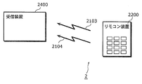
- FIG. 19 is a diagram showing a wireless remote control system including the remote control device and the reception device according to Embodiment B1 of the present invention.
- FIG. 20 is a block diagram showing an internal configuration of the remote control device according to Embodiment B1 of the present invention.
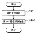
- FIG. 21 is a flowchart showing an operation of the remote control device in Embodiment B1 of the present invention.
- FIG. 22 is a flowchart showing an operation of the remote control device in Embodiment B1 of the present invention.
- FIG. 23 is a block diagram showing an internal configuration of the receiving apparatus according to Embodiment B1 of the present invention.
- FIG. 24 is a flowchart showing an operation of the reception apparatus in Embodiment B1 of the present invention.
- FIG. 25 is a block diagram showing an internal structure of the receiving apparatus according to Embodiment B2 of the present invention.
- FIG. 26 is a flowchart showing an operation of the reception apparatus in Embodiment B2 of the present invention.
- a controlled device TV 12, DVR 13, or receiving device 2400
- a wireless control device that controls the controlled device via a wireless communication path
- a remote control 11 remote control device 2200
- a wireless control system remote control system 1, wireless remote control system 2
- one of the controlled device and the wireless control device remote control 11, reception
- Device 2400 connects recognition information (pairing information, identifier) for uniquely recognizing the other device (DVR13, remote control device 2200) between the one device and the other device.
- the communication channel other than the wireless communication channel (the communication channel between the DVR 13 and the remote controller 11 via the TV 12, the first communication medium 21 And the connected device recognized via the wireless communication path are identified by the acquired recognition information.
- the wireless communication system includes a setting unit (control circuit 115, identifier determination unit 2403) that can set the connected device to communicate with the other device. This common configuration produces a common effect.
- Embodiment A relates to a wireless control device, and more specifically, to a technical field of a wireless control device that controls a controlled device via wireless communication.
- the wireless control device is a wireless control device that includes a plurality of controlled devices and a controller that controls the controlled devices via wireless communication, and is the first of the plurality of controlled devices.
- the controlled device has first recognition information which is recognition information for causing the controller to uniquely recognize the first controlled device, and among the plurality of controlled devices, the first controlled information
- a second controlled device different from the controlled device has second recognition information that is recognition information for causing the controller to uniquely recognize the second controlled device.
- the first controlled device is recognized based on the first recognition information
- the second controlled device is connected to the second controlled device when the first controlled device is connected to the second controlled device.
- the controlled device of the second recognition information Output to the first controlled device, the first controlled device outputs the second recognition information to the controller, and the controller includes the first controlled device and the second controlled device. It is characterized by recognizing a controlled device.
- Embodiment A of the present invention in a wireless control device comprising a plurality of controlled devices and a controller that controls the controlled devices via wireless communication, the first of the plurality of controlled devices.
- the controlled device has first recognition information which is recognition information for causing the controller to uniquely recognize the first controlled device, and among the plurality of controlled devices, the first controlled information
- a second controlled device different from the controlled device has second recognition information that is recognition information for causing the controller to uniquely recognize the second controlled device.
- the first controlled device is recognized based on the first recognition information
- the second controlled device is connected to the second controlled device when the first controlled device is connected to the second controlled device.
- the controlled device of the second recognition information Output to the first controlled device, the first controlled device outputs the second recognition information to the controller, and the controller includes the first controlled device and the second controlled device. It is characterized by recognizing a controlled device.
- the second controlled device When the first controlled device and the second controlled device are connected, the second controlled device outputs the second recognition information to the first controlled device, and The first controlled device accumulates the second recognition information, and when the controller and the first controlled device exchange the first recognition information via wireless communication, The first controlled device outputs the first radio control information and the second radio control information to the controller.
- the recognition information is information including at least addresses of the plurality of controlled devices and encryption keys.
- the first controlled device includes display means, and the first controlled device includes first visible information including at least a moving image and a still image generated by the first controlled device.
- a controlled device that selects and displays at least second visual information including a moving image and a still image generated by the second controlled device, wherein the controller is configured to display the first visual information in the display means.
- the visible information is displayed, it communicates with the first controlled device, and when the second visible information is displayed on the display means, it communicates with the second controlled device. It is characterized by that.
- the first controlled apparatus outputs the second recognition information to the controller when communicating with the controller while displaying the second visible information.
- the controller can appropriately control the second controlled apparatus.
- the second controlled device determines visible information displayed on the display unit, and when the visible information displayed on the display unit is determined to be the first visible information, The communication information output from the controller is rejected.
- a first controlled device among the plurality of controlled devices Has first recognition information which is recognition information for causing the controller to uniquely recognize the first controlled device, and among the plurality of controlled devices, the first controlled device and Different second controlled devices have second recognition information that is recognition information for causing the controller to uniquely recognize the second controlled device, and the controller recognizes the first recognition device.
- the second controlled device is connected when the first controlled device is connected to the second controlled device. Uses the second recognition information as the first recognition information.
- Output to the controlled device, the first controlled device outputs the second recognition information to the controller, and the controller includes the first controlled device, the second controlled device, , And a pairing method characterized by recognizing.
- a controller and a 2nd to-be-controlled device can be automatically paired, and a plurality of paired to-be-controlled devices can be appropriately switched.
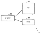
- FIG. 1 is a block diagram of a remote control system 1 of the present invention.
- the remote control system 1 includes elements indicated by reference numerals 11, 12, and 13.
- 11 is a remote control
- 12 is a TV
- 13 is a DVR (Digital Video Recorder).
- the remote controller 11 is provided with keys, and an operation command associated with each key is pressed against the TV 12 or the DVR 13 via radio waves as a communication medium when the key is pressed. Sent by.
- the TV 12 includes a display as display means, and displays a received video of a tuner built in the TV 12, and displays at least one of a moving image output from the DVR 13 and a still image.
- the TV 12 has a GUI, and controls the TV 12 using the remote controller 11.
- the DVR 13 has a GUI, and the user controls the DVR 13 by operating the GUI using the remote controller 11.
- communication between the TV 12 and the DVR 13 uses HDMI.
- communication between the TV 12 and the DVR 13 is not limited to HDMI, and any interface may be used as long as it is capable of bidirectional communication of control signals, such as Wireless HDMI.
- the radio wave is, for example, a radio wave based on a communication standard established in IEEE802.11 or other normally used non-directional signal propagation means such as Bluetooth based on a communication standard established in IEEE802.15.1. Anything can be used.
- FIG. 2 is a diagram illustrating an example of the key group 116 provided in the remote controller 11.
- the remote controller 11 includes elements indicated by reference numerals 162, 163, 170, 171, 172, 173, 174, 175, 180, 181, 182, 183, 184, 190, 191, 192, 193. .
- the remote controller 11 also includes a cross key, a channel key, and a DVR operation key.
- the cross key (upper) 171, the cross key (right) 172, the cross key (left) 173, and the cross key (lower) 174 are collectively referred to as a cross key.
- the numeric keypad 180, the channel up key 181, and the channel down key 182 are collectively referred to as channel keys.
- the volume up key 183 and the volume down key 184 are collectively referred to as a volume key.
- the play key 190, fast forward key 191, rewind key 192, and stop key 193 are collectively referred to as DVR operation keys.
- Table 1 below shows the keys of the remote controller 11 that the remote controller 11 transmits to the TV 12 when the key is pressed.
- Table 2 below shows the keys of the remote controller 11 that the remote controller 11 transmits to the DVR 13 when the key is pressed.
- Table 3 below shows the keys of the remote controller 11 whose destination of information of the key changes to either the TV 12 or the DVR 13 depending on the internal state of the remote controller 11 when the key is pressed. Show.
- the TV 12 and the DVR 13 receive the information of each key transmitted from the remote controller 11, the operations of the remote controller 11, the TV 12, and the DVR 13 will be described.
- the program information multiplexed on the broadcast wave transmitted from the broadcast station by the TV 12 is assigned to numbers 1 to 12 called channels.
- the numeric keypad 180 is composed of a key group to which channels 1 to 12 are assigned.
- the TV 12 decodes the broadcast wave transmitted from the broadcast station by the built-in tuner, and displays a moving image or a still image obtained by decoding on the display. Also, the broadcast wave of the channel corresponding to the key that has been pressed among the numeric keys 180 is selected.
- the broadcast wave of the channel obtained by adding 1 to the channel selected before the channel up key 181 is pressed is selected, decoded by the built-in tuner, and decoded.
- the obtained moving image or still image is displayed on the display. If the selected channel is 12, channel 1 is selected.
- the broadcast wave of the channel obtained by subtracting 1 from the channel selected before the channel down key 182 is pressed is selected, decoded by the built-in tuner, and decoded.
- the obtained moving image or still image is displayed on the display. If the selected channel is 1, channel 12 is selected.
- the TV 12 increases the volume.
- the volume down key 184 is pressed, the TV 12 decreases the volume.
- the DVR 13 plays the content at the normal speed.
- the rewind key 192 is pressed, the DVR 13 plays back the content while rewinding.
- the fast forward key 191 is pressed, the DVR 13 reproduces the content while fast forwarding.
- the stop key 193 is pressed, the content is stopped.
- the device operation key is valid only when the DVR 13 is in the content reproduction state.
- a menu set in the TV 12 or DVR 13 is displayed.
- the menu displays several buttons and one highlighted button.
- a function is assigned to each button, and by pressing the enter key 175, the corresponding function, that is, the function of the highlighted button is executed.
- FIG. 3 is a diagram showing the menu 1100 of the TV 12 in the embodiment of the present invention.
- 1100 is a menu
- 1101 is a program guide button
- 1102 is a DVR switching button.
- the menu 1100 is displayed, either the program guide button 1101 or the DVR switching button 1102 is highlighted.
- the program guide button 1101 is pressed, that is, when the enter key 175 is pressed while the program guide button 1101 is highlighted, the program guide menu 1110 is displayed.
- the DVR switching button 1102 is pressed, the TV 12 displays the HDMI input video on the display.
- FIG. 4 is a diagram showing the menu 1110 of the TV 12 program guide.
- 1110 is a program table
- 1111 is a time display
- 1112 is a broadcast station display
- 1113 is a program display.
- the TV 12 displays the program scheduled to be broadcast by each broadcasting station for the most recent time on the program display 1113. At this time, the TV 12 displays the images arranged in time order vertically for each broadcasting station. For the convenience of the user, the TV 12 displays a broadcast station display 1112 on the upper side of the program guide 1110 and a time display 1111 on the left side.
- the program that was displayed before the program guide 1110 was displayed is highlighted. When the cross key is pressed, the highlight moves up / down / left / right. When the enter key 75 is pressed, the highlighted broadcast station is selected.
- FIG. 5 is a diagram showing a menu 1120 of the DVR 13.
- the menu 1120 is displayed on the TV 12 by the DVR 13.
- 1120 is a menu
- 1121 is a content list button
- 1122 is a program guide button
- 1123 is a reservation list button
- 1124 is a TV switching button.
- a content list menu is displayed.
- the program guide button 1122 is executed, a program guide menu is displayed.
- the reservation list button 1123 is executed, a reservation list menu is executed.
- the TV switching button 1124 is pressed, the DVR 13 issues a command for returning the display by the TV 12 to the tuner video to the TV 12, and when this command is issued, the TV 12 displays the tuner video on the display. .
- the content list menu a list of contents recorded in the DVR 13 is displayed.
- the program guide menu a list of programs broadcasted by the broadcasting station is displayed.
- the reservation list menu a list of programs reserved for recording is displayed.
- FIG. 6 is a diagram showing a content list menu 1130.
- 1130 is a content list menu
- 1131 is a content display.
- the DVR 13 displays the recorded content information as a content display 1131.
- the displayed contents are the title, recording date, and length (time) of the content.
- the content list menu 1130 is displayed, one of the content lists 1131 is highlighted.
- the cross key is pressed, the highlighted display moves.
- the enter key 175 is pressed, the content indicated by the highlighted content display 1131 is reproduced.
- the menu of the program guide in the DVR 13 is the same as the menu 1110 (FIG. 4) of the program guide of the TV 12. However, on the TV 12, when the enter key 175 is pressed, the broadcast station of the highlighted program is selected, whereas in the menu of the program guide of the DVR 13, the highlighted program is displayed. Is scheduled for recording.
- FIG. 7 shows a reservation list menu 1140.
- 1140 is a reservation list menu
- 1141 is a reservation display.
- the DVR 13 displays the program reserved for recording as a reservation display 1141.
- the displayed contents are the broadcast station of the program, the start date and time, and the title.
- the reservation list menu 1140 is displayed, one of the reservation lists 1141 is highlighted.
- the cross key is pressed, the highlighted display moves.
- the enter key 175 is pressed, the recording reservation indicated by the highlighted reservation display 1141 is cancelled.
- a menu screen There are three types of screens that the TV 12 displays: a menu screen, a tuner video, and an HDMI input video.
- FIG. 8 is a diagram showing the state transition of the display state of the TV in the embodiment of the present invention.
- 1150 is a menu state for displaying a menu screen
- 1151 is a tuner state for displaying a tuner video
- 1152 is an HDMI input state for displaying an HDMI input video.
- 1153 is a path for transition from the tuner state 1151 to the menu state 1150
- 1154 is a path for transition from the menu state 1150 to the tuner state 1151
- 1155 is a path for transition from the HDMI input state 1152 to the tuner state 1151
- 1156 is a path for transition from the tuner state 1151 to HDMI. This is a path that makes a transition to the input state 1152.
- the TV 12 displays a menu screen (menu 1100 in FIG. 3 and menu 1110 in FIG.
- the menu state 1150 displays a tuner video in the tuner state 1151, and HDMI input video (menu 1120 in FIG. 5) in the HDMI input state 1152.
- the menu 1130 in FIG. 6 and the menu 1140 in FIG. 7 are displayed.
- the initial state of the TV 12 is a tuner state 1151.
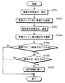
- Table 4 shows the conditions under which the path 1153, path 1154, path 1155, and path 1156 transition.
- the TV 12 When the path 1155 transits, the TV 12 notifies the DVR 13 that the TV 12 displays the TV tuner video.
- the TV 12 When the path 1156 transits, the TV 12 notifies the DVR 13 that the video of the DVR 13, that is, the TV 12 displays the output video to the TV 12.
- the TV 12 When the TV 12 receives a command of any one of the menu key 170, the cross key, and the enter key 175 from the remote controller 11 in the HDMI input state 1152, the received command is rejected.
- the remote controller 11 is notified of the address of the DVR 13 as the transmission destination address of the transmission destination to which the remote controller 11 transmits the command.
- a menu screen There are two types of screens displayed by the DVR 13: a menu screen and a content video.
- FIG. 9 is a diagram showing the state transition of the display state of the DVR 13.
- 1160 is a menu display state for displaying a menu
- 1161 is a content playback state for displaying content
- 1162 is a path for transitioning from the content playback state 1161 to the menu state 1160
- 1163 is a path for transitioning from the menu state 1161 to the content playback state 1161. is there.
- the DVR 13 displays the menu in the menu display state 1160 and the content in the content reproduction state.
- the state of the DVR 13 is set to the menu state 1160.
- Table 5 shows the conditions under which the path 1162 and the path 1163 transition.
- the DVR 13 holds a state for managing whether or not the TV 12 displays the HDMI input video.
- FIG. 10 is a state transition diagram managing the HDMI input display.
- 1180 is an HDMI display state
- 1181 is an HDMI non-display state
- 1182 is a path for transition from the HDMI non-display state 1181 to the HDMI display state 1180
- 1183 is a path for transition from the HDMI display state 1180 to the HDMI non-display state 1181.
- the DVR 13 When the DVR 13 receives a command from the remote controller 11 in the HDMI non-display state 1181, the DVR 13 rejects the command.
- Table 6 shows the conditions for the transition of the path 1182 and the path 1183.
- the DVR 13 holds HDMI display non-display information indicating whether the DVR 13 is in the HDMI display state 1180 or the HDMI non-display state 1181.
- the HDMI display non-display information is information indicating whether the TV 12 is displaying the HDMI input video.
- the remote controller 11 maintains a state in which the transmission destination of the menu key 170, the cross key (the cross key (up) 171 and the like), and the enter key 175 is managed.
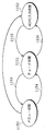
- FIG. 11 is a state transition diagram for managing transmission destinations.
- Reference numeral 1170 denotes a TV transmission state
- 1171 denotes a DVR transmission state
- 1172 denotes a path for transition from the DVR transmission state 1171 to the TV transmission state 1170
- 1173 denotes a path for transition from the TV transmission state 1170 to the DVR transmission state 1171.
- the remote controller 11 transmits these pieces of information to the TV 12.
- the remote controller 11 transmits these pieces of information to the DVR 13.
- Table 7 shows the conditions for the transition of the path 1172 and the path 1173.
- the remote control 11 and the TV 12 are each provided with a pairing push button. A case where the user presses each push button will be described.
- a pairing push button 110 of the remote controller 11 and a pairing push button 122 of the TV 12 are illustrated.
- the TV 12 When the push button 122 for pairing (see FIG. 12) is pressed, the TV 12 starts a wireless communication reception standby state, and returns a pairing acknowledgment packet when a pairing request packet is received. That is, when the pairing push button 122 (see FIG. 12) is pressed, the TV 12 enters a wireless communication reception standby state. Then, after entering the wireless communication reception standby state, the TV 12 returns a pairing acknowledgment packet to the remote controller 11 when receiving a pairing request packet from the remote controller 11.
- the pairing acknowledgment packet includes information on the device (for example, DVR 13) connected to the TV 12 in addition to the address, category, and encryption key of the TV 12. Table 8 shows device information.
- the category is a code representing the type of device such as TV or DVR.
- the encryption key is a key for encrypting the communication to be transmitted when the command is transmitted to the device. At least the communication of the pairing request packet and the communication of the pairing approval packet are performed in plain text.
- the address is an address when performing wireless communication.
- the remote control 11 transmits a pairing request packet by broadcast.
- Broadcast is a transmission method in which a transmission destination is not specified. If a packet is not transmitted by broadcast, even if it is a receiving device that receives radio communication radio waves for that packet, the packet is sent to the receiving device unless the destination specified by the packet is the receiving device. Not received.
- the packet is also received by a receiving device that is not received by non-broadcast transmission. Then, after transmitting the pairing request packet, the remote controller 11 waits for a certain period of time to wait for the remote controller 11 to receive a reply from the receiving device that has received the pairing request packet.
- information on the receiving device that has returned the received pairing acknowledgment packet is stored. Note that when a plurality of devices are included in the pairing approval packet, information on the plurality of devices is stored.
- the DVR 13 When the DVR 13 is connected to the TV 12, that is, when connected to the TV 12, the DVR 13 transmits information on the device of the DV 1 R 3, that is, the category, address, and encryption key to the TV 12.
- the TV 12 stores this information transmitted by the DVR 13, and transmits this stored information to the remote control 11 when the TV 12 is paired with the remote control 11.
- Each of the TV 12 and the DVR 13 has a command light receiving unit of a conventional infrared remote controller, and executes commands acquired by these command light receiving units.
- FIG. 12 shows a detailed block diagram of the remote control system 1 of the present invention.
- 110 is a push button (a push button for pairing), 111 is a pairing information register, 112 is a wireless transmission unit, 113 is an address register, 114 is a wireless reception unit, 115 is a control circuit, 116 is a key group, and 117 is a transmission destination Register 122, push button (push button for pairing), 123 wireless receiver, 124 address register, 125 wireless transmitter, 126 pairing information register, 127 control circuit, 128 output register, 129 Is a connected device information register, 130 is a menu generation unit, 131 is a TUNER, 132 is an HDMI input unit, 133 is a display, 134 is a selection circuit, 142 is a push button, 143 is a wireless reception unit, 144 is an address register, 145 is wireless Transmission unit, 146 is a control circuit, 147 is a pairing information register, 1 8 output register, 149 display register, 150 is a menu generation unit, 151 TUNER, 152 is HDD drive, 153 HDMI output unit, 154
- the address register 113 provided in the remote controller 11 stores the address of the remote controller 11 in advance
- the address register 124 provided in the TV 12 stores the address of the TV 12 in advance
- the address register 144 provided in the DVR 13 stores the address of the DVR 13 in advance.
- the address to be written is identification data unique to all devices including the remote controller 11 and the like.
- the wireless receiver 114 provided in the remote controller 11 discards the packet received by the wireless receiver 114 if the destination is not itself (address of the remote controller 11) and the packet is not a broadcast packet.
- the wireless reception unit 114 acquires the address of the remote controller 11 written in the address register 113 from the address register 113 provided in the remote controller 11, and sets the acquired address as its own address.
- the wireless reception unit 123 included in the TV 12 discards the packet received by the wireless reception unit 123 when the destination of the packet is not its own address (the address of the TV 12) and the packet is not a broadcast packet. Note that the wireless reception unit 123 acquires the address of the TV 12 from the address register 124 included in the TV 12, and sets the acquired address as its own address.
- the wireless reception unit 143 included in the DVR 13 discards the packet received by the wireless reception unit 143 if the destination of the packet is not its own address and the packet is not a broadcast packet. Note that the wireless reception unit 143 acquires the address of the DVR 13 from the address register 144 provided in the DVR 13, and sets the acquired address as its own address.
- the wireless transmission unit 112 included in the remote control 11 When transmitting a packet, the wireless transmission unit 112 included in the remote control 11 reads the address of the remote control 11 from the address register 113 included in the remote control 11 and uses the address as the transmission source address, and the packet whose transmission source address is the address. Send.
- the wireless transmission unit 125 included in the TV 12 reads the address of the TV 12 from the address register 124 included in the TV 12, and transmits the packet using the address as a transmission source address.
- the wireless transmission unit 145 included in the DVR 13 reads an address from the address register 144 included in the DVR 13 and transmits the packet using the address as a transmission source address.
- the packet includes a source address, a destination address, a packet type, and a payload.
- the transmission destination address may be designated by the address of the transmission destination device or broadcasted.
- the packet types include three types: pairing request, pairing approval, and command.
- the packet transmitted by the wireless transmission unit 112 of the remote controller 11 reaches the wireless reception unit 123 and the wireless reception unit 143 through the space.
- the packet transmitted by the wireless transmission unit 125 of the TV 12 reaches the wireless reception unit 114 and the wireless reception unit 143 through the space.
- the packet transmitted by the wireless transmission unit 145 of the DVR 13 reaches the wireless reception unit 114 and the wireless reception unit 123 through the space.
- the DVR 13 outputs the video from the HDMI output unit 153 to the TV 12.
- the TV 12 outputs the HDMI video input from the HDMI input unit 132 to the selection circuit 34.
- HDMI there is a data communication mechanism called CEC.
- the HDMI input unit 132 converts the data to be transmitted into CEC data
- the converted CDC data is output to the HDMI output unit 153.
- the HDMI output unit 153 receives the CDC data output from the HDMI input unit 132, decodes the received CEC data, and outputs the decoded data to the control circuit 146.
- the control circuit 146 when transmitting data from the DVR 13 to the TV 12, the control circuit 146 outputs the data to be transmitted to the TV 12 to the HDMI output unit 153, and the HDMI output unit 153 converts the data to be transmitted into CEC data. Output to the input unit 132.
- the HDMI input unit 132 receives the output CDC data, decodes the received CEC data, and outputs the decoded data to the control circuit 127.
- the HDMI input unit 132 detects that the device is connected to the TV 12 and notifies the control circuit 127 that the device is connected. When this notification is received, the control circuit 127 outputs data requesting pairing information to the connected device using the CEC. In the DVR 13, the CEC data is notified to the control circuit 146 via the HDMI output unit 153. When this notification is acquired, that is, when pairing information is requested, the DVR 13 notifies the control circuit 127 of the TV 12 of the device category, device address, and device encryption key of the DVR 13 using the CEC. To do.
- the category of the device of the DVR 13 is DVR
- the address of the device is an address read from the address register 144 by the control circuit 146 of the DVR 13 (address of the DVR 13)
- the encryption key of the DVR 13 is the control circuit 146 of the DVR 13 Is an encryption key used for communication.
- the control circuit 127 of the TV 12 accumulates the device category, device address, and device encryption key notified to the TV 12 by the DVR 13 in the connected device information register 129.
- the control circuit 115 of the remote controller 11 detects that the pairing push button 110 has been pressed, and when this is detected, requests the wireless transmission unit 112 to transmit a pairing request packet by broadcast.
- the nonce is packet confirmation data generated randomly by the control circuit 115.
- the pairing request packet has a nonce as a payload.
- the control circuit 115 of the remote controller 11 further sets the wireless reception unit 114 of the remote controller 11 in a reception standby state for a certain time, and also waits for a pairing acknowledgment packet for a certain time.
- the wireless reception unit 114 of the remote control 11 receives a packet while waiting, the wireless reception unit 114 outputs the packet, that is, the received packet to the control circuit 115 of the remote control 11. Then, if a packet is input from the wireless reception unit 114 while waiting for a pairing acknowledgment packet, the control circuit 115 determines whether the packet is a pairing acknowledgment packet.
- the control circuit 115 determines that the nonce included in the payload of the packet is the nonce at the time of the pairing request, that is, the transmitted pairing request packet. Determine if it matches nonce.
- the control circuit 115 accumulates the device information included in the payload of the packet received by the wireless reception unit 114 in the pairing information register 111.
- the device information includes a device category, a device address, and a device encryption key.
- the wireless reception unit 123 When the wireless reception unit 123 receives a packet, the wireless reception unit 123 outputs the received packet to the control circuit 127.
- the control circuit 127 determines whether or not the packet received by the wireless reception unit 123 is a pairing request packet. If it is determined that the packet is a pairing request packet, the control circuit 127 sends a pairing acknowledgment packet to the wireless transmission unit 125. When this request is acquired, the wireless transmission unit 125 transmits a pairing acknowledgment packet. At this time, the control circuit 127 notifies the wireless transmission unit 125 of the transmission destination address, nonce, TV12 category, TV12 address, and TV12 encryption key of the pairing acknowledgment packet transmitted by the wireless transmission unit 125. .
- the wireless transmission unit 125 transmits a pairing approval packet having the communicated transmission destination address and the like.
- the control circuit 127 uses the packet transmission destination as the packet transmission source address determined as the pairing request packet, the nonce as the packet nonce, the TV12 category as an identifier indicating the TV12, and the TV12 address as The address read from the address register 124 is used, and the encryption key of the TV 12 is a data string unique to the control circuit 127. Further, the control circuit 127 reads the connected device information register 129, and if there is device information stored in the connected device information register 129, the control circuit 127 displays the device category, address, and encryption key included in the device information. Then, the wireless transmission unit 125 is notified. Further, the control circuit 127 stores the source address included in the packet determined as the pairing request packet in the pairing information register 126.
- Fig. 13 shows the structure of the pairing request packet.
- 1190 is a pairing request packet
- 1191 is a transmission destination address
- 1192 is a transmission source address
- 1193 is a packet type
- 1194 is a nonce.
- an identifier indicating broadcasting is entered in the transmission destination address 1191.
- the packet type 1193 an identifier indicating a pairing request is entered.
- Fig. 14 shows the configuration of the pairing acknowledgment packet.
- 1200 is a pairing acknowledgment packet
- 1201 is a transmission destination address
- 1202 is a transmission source address
- 1203 is a packet type
- 1204 is nonce
- 1205 is a device type
- 1206 is a device address
- 1207 is a device encryption key.
- an identifier indicating a pairing acknowledgment packet is entered in the packet type 1203.
- FIG. 15 is a diagram showing that the device type 1205, the device address 1206, and the device key information 1207 are repeatedly stored when information on a plurality of devices is included.
- the pairing acknowledgment packet 1208 is a pairing acknowledgment packet for storing information of a plurality of devices.
- the pairing acknowledgment packet 1208 includes a plurality of device data including a device type 1205, a device address 1206, and device key information 1207. Different device data is data of different devices.
- the pairing information of the DVR 13 is stored in the TV 12 when the DVR 13 is connected to the TV 12, and is notified to the remote control 11 by the TV 12 when the remote control 11 and the TV 12 are paired.
- the DVR 13 can be operated by the remote controller 11 without pairing the remote controller 11 and the DVR 13.
- the control circuit 146 of the DVR 13 When the control circuit 146 of the DVR 13 detects that the pairing push button 142 included in the DVR 13 is pressed, the control circuit 146 waits for a pairing request packet for a predetermined time. When receiving a packet, the wireless reception unit 143 of the DVR 13 outputs the received packet to the control circuit 146. When the wireless reception unit 143 receives a packet while waiting for a pairing request packet and determines that the type of the packet is a pairing request packet, the control circuit 146 sends a pairing acknowledgment packet to the wireless transmission unit 145. If there is this request, the wireless transmission unit 145 transmits a pairing acknowledgment packet. Note that the control circuit 146 determines whether or not the received packet is a pairing request packet.
- the control circuit 146 makes the request to the wireless transmission unit 145.
- the control circuit 146 sends the transmission destination address, nonce, DVR13 category, DVR13 address, and DVR13 encryption key of the pairing acknowledgment packet transmitted by the wireless transmission unit 145 to the wireless transmission unit 145.
- the wireless transmission unit 145 transmits a pairing acknowledgment packet having the notified transmission destination address and the like.
- the control circuit 146 sets the transmission destination of the pairing approval packet notified to the wireless transmission unit 145 as the transmission source address of the pairing request packet, the nonce as the nonce of the pairing request packet, and the category of DVR13 indicates DVR13.
- the address of the DVR 13 is an address read from the address register 144, and the encryption key of the DVR 13 is a data string unique to the control circuit 146. Further, the control circuit 146 stores the source address of the received pairing request packet in the pairing information register 147.
- control circuit 115 When the control circuit 115 detects that a key included in the key group 116 has been pressed, the control circuit 115 determines whether the control circuit 115 key belongs to Table 1, Table 2, or Table 3 based on the table. Then, if the pressed key is a key belonging to Table 1, the control circuit 115 determines the transmission destination as TV. If the pressed key is a key belonging to Table 2, the control circuit 115 determines the transmission destination as DVR.
- the transmission destination register 117 is a register for determining a transmission destination of keys belonging to Table 3, and holds TV12 or DVR13 as a value.
- the transmission destination register 117 holds either the value indicating the TV 12 or the value indicating the DVR 13, and indicates the transmission destination of the key belonging to Table 3 by the device indicated by the held value.
- the control circuit 115 determines the device indicated by the destination register 117 as the key destination in Table 3. If the pressed key belongs to Table 3, the control circuit 115 reads the transmission destination register 117. If the read value is TV12, the transmission destination is TV12, and if it is DVR13, the transmission destination is DVR13. decide.
- the control circuit 115 extracts the information on the device whose device attribute is the TV 12, that is, the device address and the device encryption key from the pairing information register 111.
- the control circuit 115 determines that the transmission destination is DVR 13
- the control circuit 115 extracts the device information whose device attribute is DVR 13, that is, the device address and the device encryption key, from the pairing information register 111.
- the transmission destination is determined to be DVR, if there is no information on the device having the device attribute DVR13, the processing is terminated.
- the control circuit 115 uses the command, which is a data string indicating the pressed key, as the payload of the packet to be transmitted, and further encrypts the payload with the device encryption key. That is, the control circuit 115 transmits a packet having an encrypted payload.
- the control circuit 115 notifies the wireless transmission unit 112 of the encrypted command and the device address, and transmits to the wireless transmission unit 112 the command packet that is the command notified of the command and the device of the address notified by the destination. Request.
- the wireless transmission unit 112 assembles and transmits the command packet.
- control circuit 115 sets the wireless reception unit 114 to wait for a certain period of time, and sets the control circuit 115 itself to wait for reception after outputting the command packet for a certain time. To do.
- FIG. 16 is a diagram showing the structure of the command packet.
- 1210 is a command packet
- 1211 is a destination address
- 1212 is a source address
- 1213 is a command type
- 1214 is an encrypted command.
- the wireless transmission unit 112 transmits the device address notified from the control circuit 115 as the transmission destination address, the identifier indicating the command packet as the command type 1213, and the encrypted command notified from the control circuit 115 as the encrypted command 1214. Store the command.
- the wireless reception unit 114 When the wireless reception unit 114 receives a packet while waiting for reception, it notifies the control circuit 115 of the packet.
- the control circuit 115 determines the packet type. If the received packet is a reject packet and the transmission destination of the packet is DVR, the value of the transmission destination register 117 is changed to TV. If the received packet is a redirect packet, the destination address is extracted from the redirect packet. Then, the same device as the transmission destination address is searched from the pairing information register 111. If there is the same device, the value of the destination register 117 is changed to the type of the searched device, and the command packet is transmitted again. At this time, the control circuit 115 determines the transmission destination based on the value of the new transmission destination register 117. The value of the destination register 117 corresponds to the TV transmission state 1170 for TV and the DVR transmission state 1171 for DVR.
- the video output operation of the TV 12 will be described.
- the TV 12 has three video sources. One is a menu generated by the menu generation unit 130, one is a program received by the TUNER 31, and the last is a video of the DVR 13 input by the HDMI input unit 132.
- the output register 128 is a register that accumulates which of these three videos is output to the display 133.
- the output register 128 takes one of the three values of menu, TV, and DVR.
- the control circuit 127 changes the output register 128 every time the video output is changed.
- the selection circuit 134 receives the video generated or input by the menu generation unit 130, the TUNER 131, and the HDMI input unit 132, selects the input according to the value of the output register 128, and displays it on the display.
- the wireless reception unit 123 When receiving the packet transmitted by the wireless transmission unit 112 of the remote controller 11, the wireless reception unit 123 outputs the received packet to the control circuit 127.
- the control circuit 127 determines whether the packet is a command packet. If the packet is a command packet, the control circuit 127 performs the operation shown in Table 9. .
- the menu generation unit 130 generates the menu 1100 of the TV 12 in FIG. 3 and the menu 1110 of the program guide in FIG. 4 according to the command input to the TV 12, and selects the generated menu 1100 of the TV 12 in FIG. In addition to outputting to the circuit 134, when the DVR switching button 1102 is executed, the control circuit 127 is notified of the execution.
- control circuit 127 sets the value of the output register 128 to the value of DVR and switches the DVR to the DVR 13 through the CEC. Notice.
- the menu generation unit 130 displays the selected program display.
- the broadcast station is notified to the control circuit 127.
- the control circuit 127 changes the value of the output register 128 to the TV value and broadcasts the selected program display to the TUNER 131. Notify the station.
- the menu generation unit 30 acquires program information from the TUNER 131 and generates a program guide menu 1110.
- the control circuit 127 notifies the DVR 13 that DVR is not displayed when the value of the output register 128 is changed from the value of the DVR to another value.
- the TUNER 131 changes the broadcast station received by the TUNER 131 according to the command input to the wireless reception unit 123 and outputs the received video of the broadcast station to the selection circuit 134. Further, when the broadcast station displaying the program selected in the program guide menu 1110 is notified to the TUNER 131, the TUNER 131 receives the broadcast station.
- the TV value of the output register 128 corresponds to the tuner state 1151 (FIG. 8)
- the DVR 13 corresponds to the HDMI input state 1152
- the menu corresponds to the menu state 1150.
- Fig. 17 shows the structure of the redirect packet.
- 1220 is a redirect packet
- 1221 is a destination address
- 1222 is a source address
- 1223 is a packet type
- 1234 is a redirect destination address.
- the packet type 1223 stores an identifier indicating a redirect packet
- the redirect destination address 1224 stores the address of the device stored in the connected device information register 129 and the device type is DVR13.
- the control circuit 127 changes the value of the output register 128 to the value of TV.
- the operation of DVR 13 will be described.
- the DVR 13 has a recording reservation function for recording a broadcast program designated in advance by the user in the HDD and a playback function for reproducing the recorded broadcast program.
- the output register 148 is a register indicating a video output from the DVR 13, and takes a menu and content as values.
- the output register 148 holds the menu value to indicate that the output video is a menu video, and holds the content value to indicate that the output video is a content video.
- the menu generation unit 150 creates a menu instructed by the control circuit 146, and outputs the created menu data to the switch 155.
- the HDD drive 152 outputs the content instructed by the control circuit 146 to the decoder 154.
- the decoder 154 decodes the input content, converts it into video, and outputs it to the switch 155.
- the switch 155 reads the value of the output register 148.
- the switch 155 outputs the output of the menu generation unit 150 to the HDMI output unit 153. If the value is a content value, the video of the decoder 154 is output. Are output to the HDMI output unit 153.
- the display register 149 is a register indicating whether or not the video output from the DVR 13 is displayed on the TV 12, and displays or hides the value.
- the control circuit 146 When the DVR switch is notified from the TV 12 via the HDMI output unit 153, the control circuit 146 causes the menu generating unit 150 to generate the menu 1120 of the DVR 13. Further, the control circuit 146 sets a display value, that is, a value indicating that the video output from the DVR 13 is displayed on the TV 12 in the display register 149. Further, when DVR non-display is notified from the TV 12 via the HDMI output unit 153, the control circuit 146 sets a non-display value in the display register.
- the wireless reception unit 143 outputs the received packet to the control circuit 146 when the wireless reception unit 143 receives the packet.
- the control circuit 146 determines whether the packet is a command packet. The operation shown in FIG.
- the menu generation unit 150 responds to a command input to the DVR 13 with the DVR menu 1120 in FIG. 5, the program guide menu 1110 in FIG. 4, the content list menu 1130 in FIG. 6, and the reservation list menu 1140 in FIG. Are output to the switch 155, respectively.
- the menu generation unit 150 acquires program information from the TUNER 151 and generates a program guide menu 1110.
- the menu generation unit 150 acquires a content list from the content list 157 and generates a menu 1130 for the content list.
- the menu generation unit 150 acquires a reservation list from the reservation list 156 and generates a reservation list menu 1140.
- Menu generation unit 150 notifies control circuit 146 of TV switching when TV switching button 1124 (FIG. 5) is pressed.
- the control circuit 146 changes the value of the display register 149 to a non-display value and notifies the TV 12 of the TV switching through the HDMI output unit 153.
- the menu generation unit 150 notifies the control circuit 146 of the content, that is, the content selected by pressing.
- the control circuit 146 requests the HDD drive 152 to reproduce the content notified by the menu generation unit 150 and changes the value of the output register 148 to the value of the content.
- the program display 1113 (FIG. 4) is pressed, the menu generation unit 150 adds the pressed program to the reservation list 156.
- the menu generation unit 150 deletes the reservation from the reservation list 156 (FIG. 12).
- the menu generation unit 150 has a clock, and when the time indicated by the clock reaches the time at which the program reservation is started, notifies the TUNER 151 of the reservation and deletes the reservation from the reservation list 156.
- the TUNER 151 selects a broadcast station of the reserved program notified by the menu generation unit 150, requests the HDD drive 152 to record, and notifies the HDD drive 152 of the content name.
- the HDD drive 152 records the notified reserved content and adds the content to the content list 157.
- the HDD drive 152 performs constant-speed playback, fast-forward playback, rewind playback, and stop, respectively, when commands of the play key 190, fast-forward key 191, rewind key 192, and stop key 193 (FIG. 2) are notified. .
- FIG. 18 shows the structure of the reject packet.
- 1230 is a rejection packet
- 1231 is a transmission destination address
- 1232 is a transmission source address
- 1233 is a packet type.
- the transmission destination address 1191 the transmission source address of the command packet is entered
- the packet type 1233 an identifier indicating the rejection packet is entered.
- the wireless remote controller that controls a plurality of devices needs to be paired with each device, which can solve the complicated problem. That is, for example, as briefly shown in FIG. 3 and the like, when the DVR 13 is connected to the TV 12 via HDMI in the remote control 11 that controls the TV 12 and the DVR 13 (Digital Video Recorder) via wireless communication, the DVR 13 Radio control information such as an address and an encryption key is transmitted to T1V2 using CEC, and the TV 12 stores the information.
- the TV 12 and the remote controller 11 are paired, the TV 12 not only notifies the remote control 11 of the radio control information of the TV 12 but also notifies the remote control 11 of the accumulated radio control information of the DVR 13.
- the user can control the DVR 13 with the remote controller 11 without pairing the remote controller 11 with the DVR 13.
- the embodiment B relates to an identification method, a remote control device, a reception device, and a wireless remote control system.
- the present invention relates to an identification method for automatically identifying a device, a remote control device, a reception device, and a wireless remote control system.
- the identification method of the embodiment B is an identification method in which the receiving device in the wireless remote control system identifies the remote control device, and the remote control device has confirmed that the button provided on the remote control device has been operated.
- an identifier representing the remote control device is transmitted via a first communication medium that can be transmitted only within the line-of-sight range, and the identifier and operation information for operating the receiving device are transmitted to the second communication medium.
- the receiving device acquires identifiers from the first communication medium and the second communication medium transmitted by the remote control device, and determines whether or not both identifiers match.
- the transmission source is identified by this.
- this identification method when a user operates a button or the like, an operation is performed via the first communication medium and the second communication medium that can be transmitted from the remote control device to the receiving device only within the line-of-sight range. An identifier representing the performed remote control device and operation information are transmitted. In the receiving device, it is automatically determined whether or not the transmission sources of the two communication media are the same from the identifiers acquired via the first communication medium and the second communication medium. It becomes possible.
- the wireless remote control system is a wireless remote control system including a remote control device that transmits operation information according to a key operation, and a reception device that receives the operation information transmitted from the remote control device.
- the remote control device includes one or more operation keys, an operation information generation unit that generates operation information corresponding to the operation keys when the operation key is detected, and the operation information generation
- An identifier storage unit that stores an identifier representing the original, a first transmission unit that transmits the identifier via a first communication medium that can be transmitted only within the line-of-sight range, the identifier, and the operation information
- a second transmission unit for transmitting via the first communication medium, wherein the reception device receives a first reception unit for receiving an identifier representing the remote control device via the first communication medium, and a second communication unit.
- An identifier is acquired from each of the second receiving unit that receives the operation information and the identifier transmitted from the remote control device via the medium, the first communication medium, and the second communication medium.
- An identifier determination unit that identifies a transmission source by determining whether or not they match, and an operation corresponding to the operation information received from the second communication medium when the determination unit determines that they match And an operation execution unit.
- the wireless remote control system of the embodiment B when the user operates an operation key provided on the remote control device, the first communication that can be transmitted only from the remote control device to the receiving device within the line-of-sight range.
- An identifier representing the remote control device that has performed the operation via the medium and the second communication medium, and operation information are transmitted.
- identifiers are respectively acquired from the first communication medium and the second communication medium, it is determined whether or not the acquired identifiers match, and only when the two identifiers match, the remote controller The operation requested by the device can be executed.
- Embodiment B for example, even in a situation in which operation information is transmitted from a plurality of remote control devices to the reception device, the user can perform setting or switching for causing the reception device to identify the remote control device. It is not necessary to perform prior settings such as operation, and only the target remote control device can be automatically recognized by the receiving device.
- a receiving method in a wireless remote control system is an identification method for identifying a remote control device, and the remote control device detects that a button provided on the remote control device has been operated.
- the identifier representing the remote control device is transmitted via a first communication medium that can be transmitted only within the line-of-sight range, and the identifier and operation information for operating the receiving device are transmitted via the second communication medium.
- the receiving device obtains identifiers from the first communication medium and the second communication medium transmitted by the remote control device, and determines whether or not both identifiers match. It is characterized by identifying the transmission source.
- this identification method when a user operates a button or the like, an operation is performed via the first communication medium and the second communication medium that can be transmitted from the remote control device to the receiving device only within the line-of-sight range. An identifier representing the performed remote control device and operation information are transmitted. In the receiving device, it is automatically determined whether or not the transmission sources of the two communication media are the same from the identifiers acquired via the first communication medium and the second communication medium. it can.
- the user needs to perform setting such as installation settings for causing the receiving device to identify the remote control device or a prior setting such as a switching operation. Therefore, only the target remote controller can be automatically recognized by the receiver.
- infrared light may be used for the first communication medium.
- an identifier representing the remote control device is transmitted from the remote control device to the receiving device via infrared, and the identifier is transmitted via the second communication medium.
- the operation information corresponding to the button operation is transmitted.
- the receiving device from the identifier acquired via infrared and the identifier acquired via the second communication medium, it is automatically determined whether or not the transmission sources of the two communication media are the same. it can.
- the user needs to perform setting such as installation settings for causing the receiving device to identify the remote control device or a prior setting such as a switching operation.
- setting such as installation settings for causing the receiving device to identify the remote control device or a prior setting such as a switching operation.
- radio waves may be used for the second communication medium.
- an identifier representing the remote control device operated via infrared rays and radio waves and operation information are transmitted from the remote control device to the receiving device.
- the receiving device it is possible to automatically determine whether or not the transmission sources of the two communication media are the same from the respective identifiers acquired via infrared rays and radio waves.
- the user can perform installation setting or a switching operation for causing the receiving device to identify the remote control device. There is no need to perform prior setting or the like, and only the target remote control device can be automatically recognized by the receiving device.
- the wireless remote control system includes a remote control device that transmits operation information according to a key operation and a reception device that receives the operation information transmitted from the remote control device, wherein the remote control device includes one or more remote control devices.
- An operation key an operation information generation unit that generates operation information corresponding to the operation key when it is detected that the operation key has been operated, and an identifier that stores an identifier representing a generation source of the operation information
- a storage unit a first transmission unit that transmits the identifier through a first communication medium that can be transmitted only within a line-of-sight range, and the identifier and the operation information are transmitted through a second communication medium.
- a second transmission unit wherein the reception device is transmitted from the remote control device via the first communication unit and the first reception unit that receives the identifier representing the remote control device via the first communication medium.
- the first communication medium that can be transmitted from the remote control device to the receiving device only within the line-of-sight range, and the second An identifier representing the remote control device that has been operated via the communication medium and operation information are transmitted.
- the receiving device identifiers are respectively acquired from the first communication medium and the second communication medium, it is determined whether or not the acquired identifiers match, and only when the two identifiers match, the remote controller The operation requested by the device can be executed.
- the user needs to perform setting such as installation settings for causing the receiving device to identify the remote control device or a prior setting such as a switching operation.
- setting such as installation settings for causing the receiving device to identify the remote control device or a prior setting such as a switching operation.
- an infrared ray may be used for the first communication medium in the remote control device.
- an identifier representing the remote control device is transmitted via infrared, and the identifier is transmitted via the second communication medium, Operation information corresponding to the key operation can be transmitted.
- the remote control device when transmitting operation information to the receiving device, the user does not need to make a preset setting such as installation setting or switching operation for specifying the remote control device.
- the remote control device can be properly identified by forgetting to make a preset. If not, it is possible to reduce malfunctions such as operation of a television that is not the target.
- the operation can be executed only when the remote control device and the receiving device are arranged at positions that linearly face each other.
- a radio wave may be used as the second communication medium in the remote control device.
- this wireless remote control system when a user operates an operation key provided on the remote control device, an identifier representing the remote control device is transmitted via infrared, and the identifier and the key operation are transmitted via radio waves. Corresponding operation information can be transmitted.
- the user does not need to perform setting such as installation setting or switching operation for specifying the remote control device, and the remote control device. It is possible to automatically identify the target remote control device with respect to the receiving device arranged at a position linearly opposite to.
- the identifier determination unit provided in the receiving device stores an identifier obtained via the first communication medium and an identifier obtained via the second communication medium.
- the transmission source may be identified by determining whether or not the stored identifiers match.
- the identifier representing the remote control device is received via the first communication medium, and the operation information and the identifier are further received via the second communication medium. Then, identifiers obtained via the first communication medium and the second communication medium are stored, and the operation requested by the remote control device can be executed only when the stored two identifiers match.
- the target remote control device can be automatically identified. It is not necessary to make a pre-setting such as an installation setting or a switching operation for specifying the image, and it is possible to execute only a target operation.
- FIG. 19 is a configuration diagram of a wireless remote control system 2 including a remote control device 2200 and a reception device 2400.
- the remote control device 2200 and the receiving device 2400 are configured to be able to communicate via the first communication medium 2103 and the second communication medium 2104 that can be transmitted within the line-of-sight range.
- within the line-of-sight range specifically means, for example, within a range that can be seen from the position of the device that communicates with the first communication medium 2103.
- the transmission range of the first communication medium 2103 constitutes a part of the second communication medium 2104.
- the transmission range of the first communication medium 2103 is narrower than the transmission range of the second communication medium 2104.
- the remote control device 2200 When the user of the wireless remote control system 2 operates an operation key provided on the remote control device 2200, the remote control device 2200 includes operation information corresponding to the operation key and an identifier representing the remote control device 2200 that is a transmission source.
- the data can be transmitted to the receiving device 2400 via the first communication medium 2103 and the second communication medium 2104 that can be transmitted within the line-of-sight range.
- remote controller 2200 transmits only the identifier via first communication medium 2103 and transmits the identifier and operation information via second communication medium 2104.
- the remote controller 2200 is not limited to a television remote controller provided with a plurality of push button switches, and may be a pointing device such as a mouse, a trackball, or a joystick, or a remote controller provided with a touch panel. Absent.
- the receiving device 2400 receives an identifier representing the remote control device 2200 from the remote control device 2200 via the first communication medium 2103 that can be transmitted within the line-of-sight range. Furthermore, the reception device 2400 receives operation information indicating an operation content from the user to the remote control device 2200 and an identifier via the second communication medium 2104. Then, it is determined whether or not the two identifiers acquired from the first communication medium 2103 and the second communication medium 2104 match, and the user requests only when it is identified (determined) as matching. An operation process, that is, an operation process indicated by the operation information is executed.
- the receiving device 2400 can distinguish between a signal from a device other than the remote control device 2200 and an operation signal from the remote control device 2200.
- the target remote control device is the remote control device 2200.
- the receiving device 2400 is not limited to a television, and an electronic device that can be remotely operated, such as a DVD recorder, may be used.
- the receiving device 2400 to identify (process), specifically, the entire wireless remote control system 2 is processed by the part (receiving device 2400) of the entire (wireless remote control system 2) (reception device 2400). Identification), that is, a part (receiving device 2400) performs the processing (identification).
- the first communication medium 2103 that can be transmitted within the line-of-sight range transmits an identifier representing the remote control device 2200.
- the first communication medium 2103 may be any communication medium that can be transmitted only within the line of sight. For example, directional infrared light may be used, non-directional sound waves, ultrasonic waves, etc. May be used.
- the second communication medium 2104 transmits an identifier representing the remote control device 2200 and operation information generated when the user operates a button or the like.
- the second communication medium 2104 may be any communication medium that can transmit operation information.
- the second communication medium 2104 may be a radio wave based on a communication standard established in IEEE 802.11 or a communication standard established in IEEE 802.15.1.
- a communication medium such as Bluetooth may be used.
- remote control device 2200 used in wireless remote control system 2 according to Embodiment B1 of the present invention will be described.
- FIG. 20 is a block diagram of components of remote control device 2200 according to Embodiment B1.
- a remote control device 2200 according to the present invention includes an operation information generation unit 2201, an identifier storage unit 2202, a first transmission unit 2203, and a second transmission unit 2204.
- “configured” as used herein specifically means that, for example, the whole (remote control device 2200) includes each part (operation information generation unit 2201 and the like). The whole may further include parts other than those parts, or may be composed of only those parts.
- the operation information generation unit 2201 and the like are functional blocks of functions that the remote control device 2200 has.
- the functions of the remote control device 2200 include the functions of the operation information generation unit 2201 and the like.
- the function of each functional block such as the operation information generation unit 2201 may be a function realized by one object in a computer program in an object-oriented language, for example.
- Each function may be a function realized by two or more objects.
- the function of each functional block may be a function realized by one function.
- at least a part of each function described below included in remote control device 2200 may be a function realized by hardware.
- the operation information generation unit 2201 detects that the user has operated an operation key provided on the remote control device 2200, and when this operation is detected, operation information corresponding to the operation key (information specifying the operation) is detected.
- the generated operation information is output to the second transmission unit 2204.
- the operation information generating unit 2201 When the operation information generating unit 2201 generates the operation information, for example, the operation information generating unit 2201 stores data that associates the operation keys with the operation information stored in a storage memory or the like provided in the operation information generating unit 2201. You may utilize, and you may utilize the data processing result of the information regarding an operation key.
- the operation information generation unit 2201 may specifically include a correspondence storage unit that stores operation information that specifies an operation with the operation key in association with the operation key.
- the operation information generation unit 2201 may generate appropriate operation information by acquiring the operation information that the correspondence storage unit corresponds to the operated operation key.
- the operation information generation unit 2201 specifically includes a calculation function for calculating appropriate operation information by performing operations on the operation keys, and by performing this calculation, appropriate operation information is obtained. It is good also as what produces
- the identifier storage unit 2202 stores an identifier uniquely representing the remote control device 2200, and outputs the stored identifier to the first transmission unit 2203 and the second transmission unit 2204, respectively.
- the identifier may be any information that can uniquely represent the remote control device 2200. For example, all or part of a MAC address (Media Access Control Address) assigned to a network device for wireless communication is an identifier. More specifically, for example, the lower 24 bits of the MAC address may be used as an identifier, or bit data obtained by bitizing the time when the user operates the operation key is used as an identifier. You may use as.
- MAC address Media Access Control Address
- the identifier may be generated in advance corresponding to the remote control device 2200, and the generated information may be stored in the identifier storage unit 2202 as an identifier.
- the identifier storage unit 2202 may be configured to generate an identifier and store the generated identifier.
- the identifier generation timing may be synchronized with the operation information generation timing, or may be generated before or after the operation information is generated by providing a time difference from the operation information generation.
- the identifier storage unit 2202 may generate the identifier and generate the operation information by synchronizing one with the other or without performing synchronization.
- the stored identifier is, for example, data for identifying remote control device 2200 from among predetermined devices that have a possibility of transmitting the identifier to receiving device 2400.
- the first transmission unit 2203 transmits the identifier stored in the identifier storage unit 2202 via the first communication medium 2103 that can be transmitted within the line-of-sight range of the remote control device 2200.
- the second transmission unit 2204 transmits the operation information generated in the operation information generation unit 2201 and the identifier stored in the identifier storage unit 2202 via the second communication medium 2104. Note that the transmission timing in the second transmission unit 2204 may be synchronized with the first transmission unit 2203, or a time difference may be provided from the transmission of the first transmission unit 2203, whichever comes first.
- remote control device 2200 used in wireless remote control system 2 according to Embodiment B1 of the present invention will be described.
- FIG. 21 shows a flowchart until the identifier is transmitted from the first transmission unit 2203 in the remote controller 2200.
- the remote control device 2200 acquires an identifier from the identifier storage unit 2202 and outputs the acquired identifier to the first transmission unit 2203 (S301).
- the first transmission unit 2203 can transmit information within the line-of-sight range of the remote control device 2200.
- the output identifier is transmitted using 2103 as a carrier wave, and the operation is terminated (S302).
- FIG. 22 shows a flowchart of a process in which the identifier and the operation information are transmitted from the second transmission unit 2204 in the remote control device 2200.
- the operation information generation unit 2201 generates operation information, and the operation information generation unit 2201 outputs the generated operation information to the second transmission unit 2204 (S303).
- remote controller 2200 When remote controller 2200 detects that the user has operated the operation key, it acquires the identifier stored in identifier storage unit 2202 from identifier storage unit 2202, and uses the acquired identifier as second transmission unit 2204. (S304).
- the second transmission unit 2204 uses the second communication medium 2104 as a carrier wave to notify the identifier and the operation.
- Information is transmitted and the operation is terminated (S305). It should be noted that either the generation of the operation information or the acquisition of the identifier may be performed first in time or may be performed in parallel.
- the operation timing of the second transmission unit 2204 may be synchronized with the operation of the first transmission unit 2203, for example, by the second transmission unit 2204, or may be provided with a time difference.
- the operation information corresponding to the operation key and the identifier indicating the transmission source of the transmission are provided. Is automatically generated and the identifier and the operation information are transmitted using the first communication medium 2103 and the second communication medium 2104 that can be transmitted only within the line-of-sight range.
- identifier storage unit 2202 generates an identifier at the timing when the operation key is operated, but the identifier is generated in advance, and the generated identifier is stored in advance. It may be stored in the identifier storage unit 2202.
- reception apparatus 2400 used in wireless remote control system 2 in Embodiment B1 of the present invention will be described.
- FIG. 23 is a block diagram of components of receiving apparatus 2400 of Embodiment B1.
- a receiving apparatus 2400 according to the present invention includes a first receiving unit 2401, a second receiving unit 2402, an identifier determining unit 2403, and an operation information executing unit 2404.
- the first receiving unit 2401 receives the identifier via the first communication medium 2103, and when this is received, notifies the identifier determining unit 2403 that this reception has been made.
- the second reception unit 2402 receives the operation information and the identifier via the second communication medium 2104, and when this is received, notifies the identifier determination unit 2403 that the reception has been performed.
- the identifier determination unit 2403 receives the notification from the first reception unit 2401 and acquires the identifier from the first communication medium 2103. Further, upon receiving a notification from the second receiving unit 2402, the identifier determining unit 2403 acquires an identifier and operation information from the second communication medium 2104. Then, the identifier determination unit 2403 determines whether or not the acquired identifiers match, and outputs the operation information to the operation information execution unit 2404 only when the identifiers are identified (determined) as matching. . That is, the identifier determination unit 2403 determines whether or not the identifier acquired by the first communication medium 2103 matches the identifier acquired by the second communication medium 2104.
- the identifier determination unit 2403 If it is determined in this determination that the identifiers do not match, the identifier determination unit 2403 does not output the operation information acquired by the second communication medium 2104 to the operation information execution unit 2404. On the other hand, the identifier determination unit 2403 outputs the acquired operation information to the operation information execution unit 2404 when it is determined in this determination that they match. Note that the identifier determination unit 2403 may use any matching determination algorithm.
- the operation information execution unit 2404 executes an operation corresponding to the output operation information.
- FIG. 24 is an operation flowchart of receiving apparatus 2400 in Embodiment B1.
- the receiving device 2400 receives data transmitted from the remote control device 2200 to the receiving device 2400 through the first communication medium 2103 in the first receiving unit 2401 (S501). That is, in S501, the first receiving unit 2401 receives an identifier from the first communication medium 2103.
- the receiving device 2400 receives data transmitted from the remote control device 200 to the receiving device 2400 through the second communication medium 2104 in the second receiving unit 2402 (S503).
- the identifier determination unit 2403 acquires an identifier from the first communication medium 2103 (S502). For example, in S502, specifically, the identifier determination unit 2403 extracts an identifier from the data previously received by the first reception unit 2401 in S501.
- the identifier determination unit 2403 acquires (extracts) the operation information and the identifier from the second communication medium 2104 (S504). For example, in S504, specifically, the identifier determination unit 2403 extracts an identifier from the data previously received by the second reception unit 2402 in S503. Note that the identifier acquisition timing (extraction timing) is determined by the first receiving unit 2401 and the second receiving unit 2402 by receiving the identifier from the first communication medium 2103 and the operation information from the second communication medium 2014.
- the timing at which both receptions of the identifiers are detected may be used (that is, the extraction may be performed after both receptions are performed), or the second communication medium
- the identifier may be acquired from the first communication medium 2103 before or after the identifier is acquired from 2104.
- the identifier determination unit 2403 determines whether or not the identifier received via the first communication medium 2103 matches the identifier received via the second communication medium 2104. When the identifier determination unit 2403 is identified (determined) as being coincident, it outputs the acquired operation information to the operation information execution unit 2404 (S505: Yes). If the identifiers do not match, the remote controller 2200 ends the operation of FIG. 24 as it is (S505: NO).
- the operation information execution unit 2404 acquires the operation information output from the identifier determination unit 2403 (S505: Yes), and the operation information execution unit 2404 executes the process of the operation indicated by the acquired operation information. The operation is terminated (S506).
- Embodiment B1 of the present invention for example, even in a situation in which operation information is transmitted from a plurality of remote control devices to receiving device 2400, the user can make installation settings for causing receiving device 2400 to specify remote control device 2200. Alternatively, it is not necessary to perform a prior setting such as a switching operation, and only the operation from the target remote control device can be identified in the receiving device.
- the user can transmit the remote control device 2200 to the receiving device 2400 only through the first communication medium 2103 and the second communication medium 2104 that can be transmitted only within the line-of-sight range.
- the remote control device 2200 transmits an identifier representing the remote control device 2200 that performed the operation and operation information.
- two identifiers (first communication medium 2103, second communication medium 2104) are obtained from the identifiers acquired via the first communication medium 2103 and the second communication medium 2104.
- the remote control device 2200 can be automatically identified by determining whether or not the transmission source is the same.
- the wireless remote control system 2 includes a remote control device 2200 and a reception device 2400.
- the remote control device 2200 is operated by the user and transmits operation information specifying the operation performed by the user to the receiving device 2400, thereby causing the receiving device 2400 to perform the processing of the operation.
- Receiving device 2400 receives the operation information transmitted by remote control device 2200, and processes the received operation information.
- the remote control device 2200 includes an operation information generation unit 2201, an identifier storage unit 2202, a first transmission unit 2203, and a second transmission unit 2204.
- the first transmission unit 2203 transmits an identifier to the reception device 2400 by infrared rays (first communication medium 2103).
- the transmission range of the identifier by this transmission is a range that can be seen from the position of the remote control device 2200.
- the first transmission unit 2203 may perform transmission using infrared rays when the user performs an operation on the remote control device 2200. That is, the first transmission unit 2203 performs transmission by infrared rays at the same time that operation information is transmitted by the second transmission unit 2204, which will be described in detail later, when an operation is performed. Also good.
- the second transmission unit 2204 transmits operation information and an identifier to the reception device 2400 by radio waves (second communication medium 2104).
- the identifier transmitted by the second transmission unit 2204 is an identifier that matches each other, for example, the same as the identifier transmitted by the first transmission unit 2203.
- the second transmission unit 2204 transmits operation information of the operation and an identifier.
- the first transmitter 2203 transmits an identifier using infrared rays, for example, simultaneously with the transmission of the second transmitter 2204.
- the operation information generation unit 2201 generates operation information for specifying an operation performed by the user on the remote control device 2200.
- the operation information generated by the operation information generation unit 2201 is transmitted by radio waves to the reception device 2400 by the second transmission unit 2204.
- the identifier storage unit 2202 stores, that is, stores each identifier transmitted by the first transmission unit 2203 and the second transmission unit 2204, respectively. Here, if the two identifiers are the same, one identifier is stored.
- the receiving device 2400 includes a first receiving unit 2401, a second receiving unit 2402, an identifier determining unit 2403, and an operation information executing unit 2404.
- the first receiving unit 2401 receives the identification information transmitted by the first transmitting unit 2203 of the remote control device 2200 using infrared rays.
- the second receiver 2402 receives the identification information and operation information transmitted by radio waves by the second transmitter 2204 of the remote control device 2200.
- the identifier determination unit 2403 determines whether or not the identifier extracted from the data received by the first receiving unit 2401 using infrared rays matches the identifier extracted from the data received by the second receiving unit 2402 using radio waves. judge. That is, the identifier determination unit 2403 determines whether or not the identifier received by infrared rays matches the identifier received by radio waves. More specifically, for example, when the identifier determination unit 2403 receives an identifier with infrared rays (see S501 in FIG. 24), the identifier determination unit 2403 stores the received identifier.
- the identifier determination unit 2403 thus stores the identifier transmitted by the first transmission unit 2203 of the remote control device 2200 by infrared, so that the identifier transmitted by the first transmission unit 2203 is registered by the first transmission unit 2203. Then, the identifier determination unit 2403, in each operation on the remote control device 2200 after the user's operation on the registered remote control device 2200, respectively, the identifier (2) transmitted by the second transmission unit 2204 according to the operation ( It is determined whether or not the registered identifier received by infrared rays matches (see step S504) (see step S505).
- step S505 If the identifier determination unit 2403 does not determine that they match (step S505: No), that is, if it is determined that the determined radio wave identifier is not the identifier received from the remote control device 2200, The operation information received together with the identifier is not output to the operation information execution unit 2404. On the other hand, when it is determined that they match (step S505: Yes), that is, when it is determined that the received identifier is the identifier received from the remote control device 2200, the identifier determination unit 2403 operates the operation information. The information is output to the information execution unit 2404.
- the identifier determination unit 2403 determines whether or not the identifier in radio wave transmission, which is performed simultaneously with the transmission of the identifier by infrared rays, and the registered identifier coincide with each other when the identifier is registered. May be determined. Then, the identifier determination unit 2403 may output the operation information to the operation information execution unit 2404 when it is determined that they match in this determination and it is confirmed that they match.
- the identifier determination unit 2403 overwrites the stored identifier with the received identifier if a new identifier is received in the infrared when the identifier registered in the past is stored in advance (S501). Also good. In other words, the identifier determination unit 2403 may end the storage of the stored identifier and newly start storing the received identifier.
- the remote control device When the first receiving unit 2401 receives the identifier by infrared (S501), the remote control device provides an instruction to instruct the first receiving unit 2401 to transmit an encryption key for encrypting data to the first receiving unit 2401. It may be transmitted to 2200.
- the first transmission unit 2203 receives the transmitted instruction, the first transmission unit 2203 transmits a predetermined encryption key to the first reception unit 2401 using infrared rays. Then, the first receiving unit 2401 receives the encryption key transmitted by the first transmitting unit 2203 in this way.
- the operation information execution unit 2404 stores the encryption key received in this way.
- the operation information execution unit 2404 outputs the operation information to the operation information execution unit 2404 based on the determination by the identifier registered in the identifier determination unit 2403 when the encryption key is stored. All or a part of the output operation information is decrypted with the stored encryption key. Then, the operation information execution unit 2404 performs an operation process indicated by the operation information decrypted by the decryption.
- the first receiving unit 2401 may transmit the address of the receiving device 2400 with infrared rays when the identifier determining unit 2403 determines a match (S505: Yes). Then, first transmission unit 2203 of remote control device 2200 receives the transmitted address. Remote control device 2200 stores the address thus received. When the address is stored in this way, remote control device 2200 causes only the device indicated by the stored address to perform processing corresponding to the user's operation on remote control device 2200. Specifically, for example, the second transmission unit 2204 of the remote control device 2200 detects the address of the device that receives the radio wave transmitted by the second transmission unit 2204, and the detected address is stored. It is determined whether or not the address matches, and the operation information is received by the apparatus only when it is determined that the addresses match.
- Such a wireless remote control system 2 connects one device (reception device 2400) and the other device (remote control device 2200) to another communication path (infrared rays) other than the wireless communication path (communication path using radio waves).
- the recognition information (identifier) is acquired by one device (receiving device 2400) via the communication channel.
- the connected device connected to the receiving device 2400 is a device identified by the acquired recognition information (identifier), that is, the recognition information (identifier) that matches the acquired recognition information (identifier)
- the second device (reception device 2400) receives the signal
- the other device (remote control device 2200) is identified as one device (reception device 2400).
- the setting data indicating that this specification has been made is set in the one device (reception device 2400) by the one device (reception device 2400) and communicated with the other device (remote control device 2200). Can be communicated.
- the identification information when the connection device is set to be communicable with the other device (remote control device 2200) is acquired via another communication path (infrared communication path), for example, and is complicated. It is possible to easily use appropriate identification information without requiring any switch operation. As a result, it is possible to easily prevent even an inappropriate device from being controlled by the wireless control device (remote control device 2200). In other words, only the controlled device (receiving device 2400) can be easily and reliably controlled. Can be controlled.
- Embodiment B2 Next, a wireless remote control system according to Embodiment B2 of the present invention will be described with reference to the drawings.
- FIG. 25 shows that the reception device 2400 receives the identifier obtained via the first communication medium 2103 and the identifier obtained via the second communication medium 2104 in the reception device 2400 according to Embodiment B2 of the present invention.
- FIG. 18 is a block diagram in the case where the receiving apparatus 2400 determines whether or not the stored identifiers are the same.
- identifier determination section 2403 is different, and in embodiment B2, identifier determination section 2601 including accumulation buffer section 2603 and determination section 2602. This is the point.
- the accumulation buffer unit 2603 receives the identifier from the first communication medium 2103. Acquired in the accumulation buffer unit 2603 and accumulates the acquired identifier. Further, when the second receiving unit 2402 receives the identifier from the second communication medium 2104 and the second receiving unit 2402 notifies the storage buffer unit 2603 that the storage buffer unit 2603 receives the identifier, the storage buffer unit 2603 receives the identifier from the second communication medium 2104. The identifier and operation information are acquired, and the acquired identifier and operation information are stored.
- the accumulation buffer unit 2603 When the identifier acquired via the first communication medium 2103 and the two identifiers acquired via the second communication medium 2104 are accumulated together, the accumulation buffer unit 2603 notifies the determination unit 2602. I do. In the case where an identifier is already stored in the accumulation buffer unit 2603, the stored identifier may be overwritten with the acquired identifier. Further, when the identifier is stored, the storage period of the storage buffer unit 2603 is set by the user in a predetermined setting unit of the reception device 2400, and when the storage period set by the user has passed, or the reception device 2400 When a standby state such as power off is entered, the stored identifier may be invalidated or deleted. More specifically, for example, the accumulation buffer unit 2603 may perform the above invalidation or the like when the accumulation period elapses after accumulation is started.
- the determination unit 2602 Upon receiving the notification from the accumulation buffer unit 2603, the determination unit 2602 reads the two identifiers and determines whether the two read identifiers match. The determination unit 2602 outputs the operation information to the operation information execution unit 2404 only when it is identified (determined) as matching. It should be noted that the identifier determination unit 2601 may use any matching determination algorithm.
- Embodiment B2 of the present invention the operation of receiving apparatus 2400 in Embodiment B2 of the present invention will be described. Note that when the first communication medium 2103 uses ultrasonic waves, the second communication medium 2104 uses radio waves, and a signal is transmitted from the remote control device 2200 to the receiving device 2400, there is a difference in the propagation speed of the communication medium. A case will be described.
- FIG. 26 is a flowchart showing an operation of receiving apparatus 2400 in Embodiment B2.
- the receiving device 2400 receives the radio wave transmitted from the remote control device 2200 with a high propagation speed at the second receiving unit 2402, and notifies the storage buffer unit 2603 that it has been received (S701).
- the accumulation buffer unit 2603 obtains (extracts) an identifier when the second reception unit 2402 notifies the reception of the radio wave, and accumulates the obtained identifier (S702). Specifically, for example, the accumulation buffer unit 2603 extracts an identifier included in the received data from data received by the second receiving unit 2402 by radio waves.
- the receiving device 2400 receives the ultrasonic wave with a low propagation speed transmitted from the remote control device 2200 to the receiving device 2400 in the first receiving unit 2401 and notifies the accumulation buffer unit 2603 that the reception has been received. (S703).
- the accumulation buffer unit 2603 when the first reception unit 2401 is notified of reception of the ultrasonic wave, acquires the identifier from the first communication medium 2103 and accumulates the acquired identifier (S704).
- the accumulation buffer unit 2603 detects that the two identifiers are accumulated, and outputs the accumulated two identifiers to the determination unit 2602 when the detection is made (S705: Yes).
- the receiving apparatus 2400 ends the operation of FIG. 26 as it is (S705: No).
- the determination unit 2602 determines whether the two identifiers match. When it is determined that they match, the determination unit 2602 outputs the operation information acquired from the radio wave to the operation information execution unit 2404 (S706: Yes). If the identifiers do not match, the operation is terminated as it is (S706: No).
- the operation information execution unit 2404 acquires the operation information output from the determination unit 2602, and the operation information execution unit 2404 executes an operation process for the acquired operation information, and the receiving apparatus 400 ends the operation. (S707).
- ultrasonic waves are used for the first communication medium 2103 and radio waves are used for the second communication medium 2104.
- Embodiment B2 of the present invention for example, even when the propagation speed of the first communication medium 2103 and the propagation speed of the second communication medium 2104 are different, only the target remote control device is automatically selected. Therefore, it is not necessary to perform an installation setting for specifying the remote control device or a prior setting such as a switching operation.
- the wireless control system (remote control system 1, wireless remote control system 2) is configured.
- the wireless control systems of (Embodiment A), (Embodiment B1), and (Embodiment B2) each have a wireless communication path with a controlled device (TV 12, DVR 13, or receiving device 2400).
- a wireless control system (remote control system 1, wireless remote control system 2) including a wireless control device (remote control 11, remote control device 2200) for controlling the controlled device via the control device, the wireless device
- One device (remote control 11 and receiving device 2400) of the control device has recognition information (pairing information (category, address) for uniquely identifying the other device (DVR 13 and remote control device 2200).
- Encryption key) and identifier are connected to another communication channel (TV1) different from the wireless communication channel that connects the one device to the other device.
- An acquisition unit (a wireless reception unit 114, a first reception unit 2401) for acquiring via a communication path between the DVR 13 and the remote controller 11 via the communication path, a communication path of the first communication medium 2103), and the wireless communication path
- a setting unit (control circuit 115, identifier determination unit) that sets the connected device to communicate with the other device. 2403) is configured.
- recognition information is acquired by one device via another communication path different from the wireless communication path that connects one device to the other device. And when a connection apparatus is an apparatus identified by the acquired recognition information, the said connection apparatus is set with said other apparatus, and communication is possible. For this reason, the recognition information when the connected device is set to be communicable with the other device is acquired via another communication path, so that the appropriate recognition information can be easily used. As a result, it is possible to easily prevent even an inappropriate device from being controlled by the wireless control device. In other words, it is possible to simply and reliably control only the controlled device.
- the one device determines whether the target device is connected to the one device, that is, determines whether the target device is a connected device, and determines that the target device is a connected device. You may recognize it.
- the one device recognizes that the one device is a connected device, and first recognizes that the first recognized target device (connected device) is the other device. It is good also as what performs 2 recognition.
- the one device is identified in detail as the first recognized target device (connected device) is the other device, and is identified when it is identified.
- the setting information indicating this may be set in a function unit such as the setting unit of the one device having the setting unit so that the one device and the connected device can communicate with each other.
- the said one apparatus is only 1st recognition among 1st recognition and 2nd recognition with respect to an object apparatus, and cannot perform data communication with an object apparatus while 2nd recognition is not carried out. It is also possible that data communication can be performed only after two recognitions are made.
- the one device and the other device may be able to communicate commands only after the second recognition is completed.
- the other device is a second controlled device (DVR 13), and the other communication path is defined by a second controlled device.
- Communication path through which the second recognition information of the second controlled device is output to the first controlled device, and the output second recognition information is output to the wireless control device by the first controlled device The structure which is is taken.
- the other communication path is configured to be a communication path using a first communication medium that can be transmitted only within the line-of-sight range. Therefore, the above-described other communication paths can be easily configured by adopting these configurations. Therefore, as compared with the method that does not use the other communication path, appropriate recognition information can be used relatively easily without, for example, pressing the switch.
- the pressing operation of the switch is often performed by a customer who uses the wireless control system, not the manufacturer of the wireless control system. For this reason, it is particularly strongly desired for manufacturers that this operation or the like is unnecessary.
- another communication path that is not the wireless communication path in which the wireless control apparatus controls the controlled apparatus is used for acquiring the recognition information.
- the wireless communication path can be freely selected regardless of the acquisition of the recognition information.
- a wireless communication path with less directivity for example, an omnidirectional wireless communication path
- a radio communication path using radio waves can be selected. Radio communication paths using radio waves have little directivity. As a result, it is possible to obtain the merit that control by the wireless communication path can be performed without directing the wireless control device in a certain direction, and the recognition information is not acquired on the wireless communication path of the radio wave having a wide transmission range. Can be.
- the wireless communication path is a radio communication path
- the controlled device is likely to be illegally controlled by a third party outside the wall.
- recognition information is acquired by another communication path different from such a radio communication path. Thereby, it is possible to prevent unauthorized control as described above. That is, only the wireless control device can reliably control the controlled device.
- a first controlled device (TV12) is provided together with the second controlled device (DVR13), and the first controlled device (TV12) is different in communication from the first controlled device.
- First recognition information pairing information: category, address, encryption key
- the second controlled device (DVR 13) uniquely has its own device (the second controlled device) with respect to a communication device (for example, the wireless control device) different from the second controlled device.
- the wireless control device can communicate with the first controlled device (TV 12) based on the first recognition information, A first controlled device and the second controlled device; (DVR13), the second controlled device (DVR13) outputs the second recognition information to the first controlled device (TV12), and the first controlled device is connected.
- the device outputs the second recognition information to the wireless control device (remote control 11), and the wireless control device is based on the second recognition information output from the first controlled device (TV 12).
- communication with the second controlled device (DVR 13) recognized via the wireless communication channel (the other communication channel) is enabled, and the other communication channel is connected to the first controlled device (TV12).
- the second controlled device (DVR 13) and the wireless communication channel between the first controlled device (TV 12) and the wireless control device (remote control 11).
- the radio control system according to the above (1) configured by two Made (Embodiment A).
- the second controlled device (DVR 13) transmits the second recognition information to the first controlled device.
- the first controlled device stores the second recognition information in the connected device information register 129, and the wireless control device and the first controlled device are wireless.
- the first controlled device outputs the first recognition information and the second recognition information to the radio control device.
- the wireless control system described in (2) above is configured ((Embodiment A) (Embodiment B1), (Embodiment B2)).
- the wireless control system according to (2) or (3) is configured, wherein the recognition information is information including at least addresses of the plurality of controlled devices and encryption keys.
- the first controlled device (TV12) includes display means (display 133), and the first controlled device (TV12) is at least a moving image generated by the first controlled device. And the first visible information including the still image and the second visible information including at least the moving image and the still image generated by the second controlled device (DVR13).
- the wireless control device communicates with the first controlled device (TV12) and communicates with the first controlled device (TV12).
- the wireless control system according to any one of (2) to (4) above is configured that does not communicate with a different controlled device (for example, DVR 13).
- the second controlled apparatus When the first controlled apparatus communicates with the radio control apparatus while displaying the second visible information by the second controlled apparatus (DVR13), the second controlled apparatus
- the radio control system according to the above (5) is configured, in which the second recognition information output from the control device to the first controlled device is output to the radio control device.
- the second controlled device determines the visible information displayed on the display means, and the visible information displayed on the display means is determined by the first controlled device (TV12).
- the wireless control system according to (6) is configured to reject the communication information output from the wireless control device.
- a wireless control device pairing method including a plurality of controlled devices and a wireless control device that controls the controlled device via a wireless communication path, the first of the plurality of controlled devices.
- the controlled device is identification information for uniquely identifying its own device (the first controlled device) to a communication device (such as the wireless control device) different from the first controlled device.
- a second controlled device different from the first controlled device among the plurality of controlled devices is a communication device (the wireless device) different from the second controlled device.
- Control device, etc.) having second recognition information which is recognition information for uniquely recognizing the own device (second controlled device), and the wireless control device receives the first recognition information.
- the second controlled device If it is communicable with the first controlled device based on When the first controlled device and the second controlled device are connected, the second controlled device outputs the second recognition information to the first controlled device, The first controlled device outputs the second recognition information to the wireless control device, and the wireless control device is based on the second recognition information output from the first controlled device.
- a pairing method is provided that enables communication with the second controlled device recognized via the wireless communication channel (the other communication channel).
- the controlled device identifies the wireless control device (remote control device 2200), and the wireless control device confirms that a button provided on the wireless control device has been operated.
- a first transmission unit that transmits recognition information (identifier) representing the wireless control device via a first communication medium (first communication medium 2103) that can be transmitted only within the line-of-sight range.
- One transmission unit 2203 a second transmission unit (second transmission unit) that transmits the recognition information and operation information for operating the controlled device via a second communication medium (second communication medium 2104). 2204), and the controlled device obtains recognition information from the first communication medium and the second communication medium transmitted by the wireless control device, respectively.
- the wireless control system wireless remote control system 2 described in the above (1), which is a communication path for communication using the communication medium (first communication medium 2103), is configured ((Embodiment B1), (Embodiment B2). )).
- Wireless control including a wireless control device (remote control device 2200) that transmits operation information corresponding to a key operation and a controlled device (receiving device 2400) that receives the operation information transmitted from the wireless control device.
- a wireless control device that transmits operation information corresponding to a key operation
- a controlled device that receives the operation information transmitted from the wireless control device.
- wireless remote control system 2 when the wireless control device detects that one or more operation keys and an operation of the operation keys are performed, operation information corresponding to the operation keys is displayed.
- An operation information generation unit (operation information generation unit 2201) to be generated, a recognition information storage unit (identifier storage unit 2202) that stores recognition information representing the generation source of the operation information, and the recognition information is transmitted only within the line-of-sight
- a first transmission unit (first transmission unit 2203) for transmitting via a first possible communication medium, a first transmission unit for transmitting the recognition information and the operation information via a second communication medium.
- a first receiving unit (first receiving unit 2401) that receives recognition information representing the wireless control device via the first communication medium; and a transmitting unit (second transmitting unit 2204).
- a second receiving unit (second receiving unit 2402) that receives the operation information and the recognition information transmitted from the wireless control device via the second communication medium, the first communication medium, and the second A recognition information determination unit (identifier determination unit 2601) for identifying the transmission source by acquiring recognition information from each communication medium and determining whether or not the two pieces of recognition information match, and the recognition information determination unit
- An operation execution unit (operation information execution unit 2404) that executes an operation corresponding to the operation information received from the second communication medium when it is determined that they match, the one device is the controlled device Yes, the other device is A radio control device, the other communication path, the (1) wireless control system according constitute a communication channel for communicating with the first communication medium.
- the first controlled device identifies the radio control device, and when the radio control device detects that a button provided on the radio control device is operated, A first transmitter that transmits recognition information representing the wireless control device via a first communication medium that can be transmitted only within a line-of-sight range; the recognition information; and operation information for operating the controlled device. A second transmission unit for transmitting via a second communication medium, wherein the first controlled device includes the first communication medium and the second communication medium transmitted by the wireless control device.
- the recognition information determination unit of the first controlled device When the wireless control device is identified, the first controlled device is recognized, and the second controlled device is identified by the recognition information determination unit of the first controlled device. Thus, when the first controlled device is recognized by the wireless control device, the second controlled device is connected to the second controlled device when the first controlled device and the second controlled device are connected.
- the wireless control system according to (2) may be configured to output the recognition information of the above to the first controlled device.
- the present invention can be used for a remote controller, and in particular, pairing of the second and subsequent devices is unnecessary, and the user can operate the device more easily by appropriately selecting the device when controlling a plurality of devices. Can be used for remote control.
- the identification method of the present invention compares the identifier superimposed on the first communication medium with the identifier superimposed on the second communication medium before executing the operation information, thereby generating the operation information generation source.
- recognition information is acquired by one device via another communication path different from the wireless communication path that connects one device to the other device.
- a connection apparatus is an apparatus identified by the acquired recognition information
- the said connection apparatus is set with said other apparatus, and communication is possible.
- the recognition information when the connected device is set to be communicable with the other device is acquired via another communication path, and thus, for example, a complicated switch operation can be made unnecessary.
- Appropriate recognition information can be used. As a result, it is possible to easily prevent even an inappropriate device from being controlled by the wireless control device. In other words, it is possible to simply and reliably control only the controlled device.
Landscapes
- Physics & Mathematics (AREA)
- General Physics & Mathematics (AREA)
- Engineering & Computer Science (AREA)
- Computer Networks & Wireless Communication (AREA)
- Selective Calling Equipment (AREA)
- Details Of Television Systems (AREA)
Abstract
Description
Further, in this radio control system, specifically, for example, the controlled device identifies the radio control device, and the radio control device operates a button provided on the radio control device. A first transmission unit that transmits the recognition information representing the wireless control device via a first communication medium that can be transmitted only within the line-of-sight range, the recognition information, and the first A second transmission unit that transmits operation information for operating the controlled device via a second communication medium, and the controlled device includes the first communication medium transmitted by the wireless control device, and A first acquisition unit and a second acquisition unit that respectively acquire recognition information from the second communication medium, and a recognition information determination unit that identifies a transmission source by determining whether or not both pieces of recognition information match. And the different communication path passes through the first communication medium. It may be a wireless control system that is a communication path as a communication medium.
2 ワイヤレスリモコンシステム
11 リモコン
12 TV
13 DVR
110、122、142 押しボタン
111、126、147 ペアリング情報レジスタ
112、125、145 無線送信部
113、124、144 アドレスレジスタ
114、123、143 無線受信部
115、127、146 制御回路
116 キー群
117 送信先レジスタ
128、148 出力レジスタ
129 接続機器情報レジスタ
130、150 メニュー生成部
131、151 TUNER
132 HDMI入力部
133 ディスプレイ
134 選択回路
149 表示レジスタ
152 HDDドライブ
153 HDMI出力部
154 デコーダ
155 スイッチ
156 予約一覧
157 コンテンツ一覧
2103 第一の通信媒体
2104 第二の通信媒体
2200 リモコン装置
2201 操作情報生成部
2202 識別子保存部
2203 第一送信部
2204 第二送信部
2400 実施の形態B1における受信装置
2401 第一受信部
2402 第二受信部
2403 識別子判定部
2404 操作情報実行部
2601 実施の形態B2における識別子判定部
2602 判定部
2603 蓄積バッファ部 1
13 DVR
110, 122, 142
132
実施の形態Aは、無線制御装置に関し、より具体的には、被制御装置に対して無線通信を介して制御する無線制御装置の技術分野に関する。 (Embodiment A)
Embodiment A relates to a wireless control device, and more specifically, to a technical field of a wireless control device that controls a controlled device via wireless communication.
Thereby, a controller and a 2nd to-be-controlled device can be automatically paired, and a plurality of paired to-be-controlled devices can be appropriately switched.


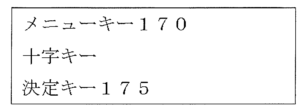


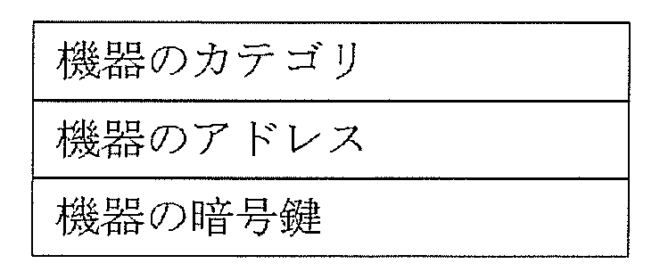


実施の形態Bは、識別方法、リモコン装置、受信装置及び、ワイヤレスリモコンシステムに関し、より詳しくは、ユーザの見通し範囲内に存在する受信装置に対して、初期の設置設定や切り替え操作なしに、リモコン装置を自動的に識別させる識別方法、リモコン装置、受信装置及び、ワイヤレスリモコンシステムに関するものである。 (Embodiment B)
The embodiment B relates to an identification method, a remote control device, a reception device, and a wireless remote control system. The present invention relates to an identification method for automatically identifying a device, a remote control device, a reception device, and a wireless remote control system.
以下、本発明の実施の形態B1におけるワイヤレスリモコンシステム2について、図面を参照しながら説明する。 (Embodiment B1)
Hereinafter, wireless
次に、本発明の実施の形態B2におけるワイヤレスリモコンシステムについて、図面を参照しながら説明する。 (Embodiment B2)
Next, a wireless remote control system according to Embodiment B2 of the present invention will be described with reference to the drawings.
Claims (18)
- 被制御機器と、無線通信路を介して前記被制御機器を制御する無線制御装置と、を備えた無線制御システムであって、
前記被制御機器および前記無線制御装置のうちの一方の機器は、
他方の機器を一意に認識するための認識情報を、当該一方の機器と前記他方の機器とを接続する前記無線通信路とは異なる通信路を介して取得し、
前記無線通信路を介して認識している接続機器が、取得された前記認識情報により識別される機器である場合、当該接続機器を前記他方の機器と設定し通信可能とする無線制御システム。 A wireless control system comprising a controlled device and a wireless control device that controls the controlled device via a wireless communication path,
One of the controlled device and the wireless control device is:
Recognizing recognition information for uniquely recognizing the other device through a communication path different from the wireless communication path connecting the one device and the other device,
When the connected device recognized via the wireless communication path is a device identified by the acquired recognition information, a wireless control system that enables communication by setting the connected device with the other device. - 第1の被制御機器と共に、第2の被制御機器を備え、
前記第1の被制御装置は、当該第1の被制御装置とは異なる通信装置に対し、自装置を一意に認識させるための認識情報である第1の認識情報を有し、
前記第2の被制御装置は、当該第2の被制御装置とは異なる通信装置に対し、自装置を一意に認識させるための認識情報である第2の認識情報を有し、
前記無線制御装置が、前記第1の認識情報を基に前記第1の被制御装置と通信可能である場合、前記第1の被制御装置と、前記第2の被制御装置と、を接続した際に、前記第2の被制御装置は、前記第2の認識情報を前記第1の被制御装置に出力し、
前記第1の被制御装置は、前記無線制御装置に前記第2の認識情報を出力し、
前記無線制御装置は、前記第1の被制御装置から出力される前記第2の認識情報を基に、前記無線通信路を介して認識している前記第2の被制御装置と通信可能とし、
前記異なる通信路は、前記第1の被制御装置と前記第2の被制御装置との間の通信路と、前記第1の被制御装置と当該無線制御装置との間の前記無線通信路との2つによって構成される請求項1記載の無線制御システム。 Along with the first controlled device, a second controlled device is provided,
The first controlled device has first recognition information that is recognition information for uniquely recognizing the own device with respect to a communication device different from the first controlled device.
The second controlled device has second recognition information that is recognition information for uniquely recognizing the own device with respect to a communication device different from the second controlled device.
When the wireless control device can communicate with the first controlled device based on the first recognition information, the first controlled device and the second controlled device are connected. The second controlled device outputs the second recognition information to the first controlled device;
The first controlled device outputs the second recognition information to the wireless control device,
The wireless control device is capable of communicating with the second controlled device recognized via the wireless communication path based on the second recognition information output from the first controlled device.
The different communication paths include a communication path between the first controlled apparatus and the second controlled apparatus, and a wireless communication path between the first controlled apparatus and the radio control apparatus. The radio control system according to claim 1, comprising: - 前記第1の被制御装置と、前記第2の被制御装置と、を接続した際に、前記第2の被制御装置は前記第2の認識情報を前記第1の被制御装置に出力し、前記第1の被制御装置は前記第2の認識情報を蓄積し、前記無線制御装置と、前記第1の被制御装置と、が無線通信路を介して前記第1の認識情報の交換を行う際に、前記第1の被制御装置は、前記第1の認識情報と、前記第2の認識情報と、を前記無線制御装置に出力する請求項2記載の無線制御システム。 When the first controlled device and the second controlled device are connected, the second controlled device outputs the second recognition information to the first controlled device, The first controlled device stores the second recognition information, and the wireless control device and the first controlled device exchange the first recognition information through a wireless communication path. 3. The wireless control system according to claim 2, wherein the first controlled device outputs the first recognition information and the second recognition information to the wireless control device.
- 前記認識情報は、少なくとも前記複数の被制御装置のアドレスと、暗号鍵と、を含む情報である請求項2または請求項3記載の無線制御システム。 4. The wireless control system according to claim 2, wherein the recognition information is information including at least addresses of the plurality of controlled devices and encryption keys.
- 前記第1の被制御装置は、表示手段を具備し、
前記第1の被制御装置は、当該第1の被制御装置で生成される少なくとも動画および静止画を含む第1の可視情報と、前記第2の被制御装置で生成される少なくとも動画および静止画を含む第2の可視情報と、を選択して表示する特徴を有し、
前記無線制御装置は、前記表示手段において前記第1の可視情報が表示されている場合は、前記第1の被制御装置と通信し、当該第1の被制御装置とは異なる被制御装置とは通信しない請求項2から請求項4の何れか1項に記載の無線制御システム。 The first controlled device comprises display means,
The first controlled device includes first visible information including at least a moving image and a still image generated by the first controlled device, and at least a moving image and a still image generated by the second controlled device. And displaying the second visible information including
The wireless control device communicates with the first controlled device when the first visible information is displayed on the display means, and is a controlled device different from the first controlled device. The wireless control system according to any one of claims 2 to 4, wherein communication is not performed. - 前記第1の被制御装置は、前記第2の可視情報を表示している際に前記無線制御装置と通信する場合、前記第2の認識情報を前記無線制御装置に出力する請求項5記載の無線制御システム。 The said 1st controlled apparatus outputs the said 2nd recognition information to the said wireless control apparatus, when communicating with the said wireless control apparatus, while displaying the said 2nd visible information. Wireless control system.
- 前記第1の被制御装置は、前記表示手段に表示される可視情報を判定し、
前記表示手段に表示される可視情報が前記第2の可視情報であると判定された場合は、前記無線制御装置から出力される通信情報を拒否する請求項6記載の無線制御システム。 The first controlled device determines visible information displayed on the display means,
The wireless control system according to claim 6, wherein when it is determined that the visible information displayed on the display means is the second visible information, communication information output from the wireless control device is rejected. - 複数の被制御機器と、無線通信路を介して当該被制御機器を制御する無線制御装置と、を備えた無線制御装置のペアリング方法において、
前記複数の被制御装置のうち第1の被制御装置は、当該第1の被制御装置とは異なる通信装置に対し、自装置を一意に認識させるための認識情報である第1の認識情報を有し、
前記複数の被制御装置のうち、前記第1の被制御装置とは異なる第2の被制御装置は、当該第2の被制御装置とは異なる通信装置に対し、自装置を一意に認識させるための認識情報である第2の認識情報を有し、
前記無線制御装置が、前記第1の認識情報を基に前記第1の被制御装置と通信可能な状態である場合、前記第1の被制御装置と、前記第2の被制御装置と、を接続した際に、前記第2の被制御装置は、前記第2の認識情報を前記第1の被制御装置に出力し、
前記第1の被制御装置は、前記無線制御装置に前記第2の認識情報を出力し、
前記無線制御装置は、前記第1の被制御装置から出力される前記第2の認識情報を基に、前記無線通信路を介して認識している前記第2の被制御装置と通信可能とするペアリング方法。 In a wireless control device pairing method comprising a plurality of controlled devices and a wireless control device that controls the controlled device via a wireless communication path,
Of the plurality of controlled devices, the first controlled device receives first recognition information that is recognition information for causing a communication device different from the first controlled device to uniquely recognize itself. Have
Of the plurality of controlled devices, a second controlled device different from the first controlled device causes a communication device different from the second controlled device to uniquely recognize itself. Second recognition information that is the recognition information of
When the wireless control device is in a state capable of communicating with the first controlled device based on the first recognition information, the first controlled device and the second controlled device are: When connected, the second controlled device outputs the second recognition information to the first controlled device,
The first controlled device outputs the second recognition information to the wireless control device,
The wireless control device can communicate with the second controlled device that is recognized via the wireless communication path based on the second recognition information output from the first controlled device. Pairing method. - 前記被制御装置は、前記無線制御装置を識別し、
前記無線制御装置は、
前記無線制御装置に設けられたボタンの操作が行われたことを検知した際に、前記無線制御装置を表す認識情報を、見通し範囲内にのみ伝送可能な第一の通信媒体を介して送信する第一送信部と、
前記認識情報と、前記第1の被制御装置を操作する操作情報とを第二の通信媒体を介して送信する第二送信部とを有し、
前記被制御装置は、
前記無線制御装置が送信した前記第一の通信媒体及び、前記第二の通信媒体とからそれぞれ認識情報を取得する第一取得部及び第二取得部と、
両認識情報が一致するか否かを判定することで送信元を識別する認識情報判定部とを備え、
前記異なる通信路は、前記第一の通信媒体を通信媒体として有する通信路である請求項1記載の無線制御システム。 The controlled device identifies the wireless control device;
The wireless control device
When it is detected that an operation of a button provided on the wireless control device has been performed, recognition information representing the wireless control device is transmitted via a first communication medium that can be transmitted only within the line-of-sight range. A first transmitter;
A second transmission unit for transmitting the recognition information and operation information for operating the first controlled device via a second communication medium;
The controlled device is:
A first acquisition unit and a second acquisition unit that respectively acquire recognition information from the first communication medium and the second communication medium transmitted by the wireless control device;
A recognition information determination unit that identifies a transmission source by determining whether or not both recognition information matches,
The radio control system according to claim 1, wherein the different communication path is a communication path having the first communication medium as a communication medium. - 請求項9に記載の無線制御システムであって、
前記第一の通信媒体に赤外線を用い、
前記第二の通信媒体に電波を用いることを特徴とする無線制御システム。 The radio control system according to claim 9,
Infrared is used for the first communication medium,
A radio control system using radio waves for the second communication medium. - キー操作に応じた操作情報を送信する無線制御装置と、前記無線制御装置から送信される前記操作情報を受信する被制御装置とを備える無線制御システムであって、
前記無線制御装置は、
一つ以上の操作キーと、前記操作キーの操作が行われたことを検知した際に、前記操作キーに対応した操作情報を生成する操作情報生成部と、
前記操作情報の生成元を表す認識情報を保存する認識情報保存部と、
前記認識情報を見通し範囲内にのみ伝送可能な第一の通信媒体を介して送信する第一送信部と、
前記認識情報と、前記操作情報とを第二の通信媒体を介して送信する第二送信部とを備え、
前記被制御装置は、
第一の通信媒体を介して無線制御装置を表す認識情報を受信する第一受信部と、
第二の通信媒体を介して無線制御装置から送信された操作情報と、認識情報とを受信する第二受信部と、
前記第一の通信媒体及び、前記第二の通信媒体とからそれぞれ認識情報を取得し、両認識情報が一致するか否かを判定することで送信元の識別を行う認識情報判定部と、
前記認識情報判定部において一致すると判定された場合、前記第二の通信媒体から受信した操作情報に対応した操作を実行する操作実行部とを備え、
前記一方の機器は、前記被制御機器であり、
前記他方の機器は、前記無線制御装置であり、
前記異なる通信路は、前記第一の通信媒体により通信する通信路である請求項1記載の無線制御システム。 A wireless control system comprising: a wireless control device that transmits operation information according to a key operation; and a controlled device that receives the operation information transmitted from the wireless control device,
The wireless control device
One or more operation keys, and an operation information generation unit that generates operation information corresponding to the operation keys when it is detected that the operation of the operation keys has been performed;
A recognition information storage unit that stores recognition information representing a generation source of the operation information;
A first transmission unit for transmitting the recognition information via a first communication medium that can be transmitted only within a line-of-sight range;
A second transmitter that transmits the recognition information and the operation information via a second communication medium;
The controlled device is:
A first receiver that receives recognition information representing the wireless control device via the first communication medium;
A second receiving unit that receives the operation information transmitted from the wireless control device via the second communication medium and the recognition information;
A recognition information determination unit that acquires identification information from each of the first communication medium and the second communication medium, and identifies a transmission source by determining whether or not the two pieces of recognition information match;
An operation execution unit that executes an operation corresponding to the operation information received from the second communication medium when the recognition information determination unit determines that they match,
The one device is the controlled device,
The other device is the wireless control device;
The radio control system according to claim 1, wherein the different communication path is a communication path that communicates with the first communication medium. - 請求項11に記載の無線制御システムであって、
前記無線制御装置における前記第一の通信媒体に、赤外線を用い、
前記無線制御装置における前記第二の通信媒体に電波を用いることを特徴とする無線制御システム。 The wireless control system according to claim 11, comprising:
Infrared rays are used for the first communication medium in the wireless control device,
A radio control system using radio waves for the second communication medium in the radio control device. - 請求項11乃至請求項12に記載の無線制御システムであって、
前記被制御装置に備えられた前記認識情報判定部は、前記第一の通信媒体を介して得られる認識情報と、前記第二の通信媒体を介して得られる認識情報とを蓄積し、当該蓄積した両認識情報が一致しているか否かを判定することで送信元の識別を行う無線制御システム。 The wireless control system according to claim 11, wherein:
The recognition information determination unit provided in the controlled device accumulates recognition information obtained through the first communication medium and recognition information obtained through the second communication medium, and stores the recognition information. A wireless control system that identifies a transmission source by determining whether or not both pieces of recognition information match. - 前記一方の機器は、
前記接続機器が前記他方の機器と認識されない場合には、当該一方の機器と前記接続機器との間での前記制御を行わせず、前記接続機器が前記他方の機器と認識される場合にのみ、前記制御を行わせる請求項1記載の無線制御システム。 The one device is
When the connected device is not recognized as the other device, the control between the one device and the connected device is not performed, and only when the connected device is recognized as the other device. The wireless control system according to claim 1, wherein the control is performed. - 被制御機器と、無線通信路を介して当該被制御機器を制御する無線制御装置と、を備えた無線制御システムにおける、前記被制御機器および前記無線制御機器のうちの一方の機器であって、
他方の機器を当該一方の機器が一意に認識するための認識情報を、当該一方の機器と前記他方の機器とを接続する、前記無線通信路とは別の他の通信路を介して取得し、
前記無線通信路を介して認識している接続機器が、取得された前記認識情報により識別される機器である場合、当該接続機器を前記他方の機器と設定し通信する機器。 In a wireless control system comprising a controlled device and a wireless control device that controls the controlled device via a wireless communication path, one of the controlled device and the wireless control device,
Acknowledgment information for uniquely recognizing the other device by the one device is acquired via another communication path different from the wireless communication path that connects the one device and the other device. ,
If the connected device recognized via the wireless communication path is a device identified by the acquired recognition information, a device that sets the connected device and communicates with the other device. - 被制御機器と、無線通信路を介して当該被制御機器を制御する無線制御装置と、を備えた無線制御システムにおける、前記被制御機器および前記無線制御装置のうちの一方の機器が行う設定方法であって、
他方の機器を当該一方の機器が一意に認識するための認識情報を、当該一方の機器と前記他方の機器とを接続する、前記無線通信路とは別の他の通信路を介して当該一方の機器が取得するステップと、
前記無線通信路を介して認識している接続機器が、取得された前記認識情報により識別される機器である場合、当該接続機器を前記他方の機器と当該一方の機器が設定する設定方法。 Setting method performed by one of the controlled device and the wireless control device in a wireless control system comprising a controlled device and a wireless control device that controls the controlled device via a wireless communication path Because
Recognizing information for uniquely recognizing the other device by the one device via the other communication path different from the wireless communication path that connects the one device and the other device. The steps of acquiring
A setting method in which, when a connected device recognized via the wireless communication path is a device identified by the acquired recognition information, the other device and the one device set the connected device. - 被制御機器と、無線通信路を介して当該被制御機器を制御する無線制御装置と、を備えた無線制御システムにおける、前記被制御機器および前記無線制御装置のうちの一方の機器におけるコンピュータプログラムであって、
他方の機器を当該一方の機器が一意に認識するための認識情報を、当該一方の機器と前記他方の機器とを接続する、前記無線通信路とは別の他の通信路を介して、当該一方の機器に取得する取得機能と、
前記無線通信路を通じて介して認識している接続機器が、取得された前記認識情報により識別される機器である場合、当該接続機器を前記他方の機器と設定し通信可能とする機能とを前記一方の機器に実現させるためのコンピュータプログラム。 A computer program in one of the controlled device and the wireless control device in a wireless control system comprising a controlled device and a wireless control device that controls the controlled device via a wireless communication path There,
The recognition information for uniquely recognizing the other device by the one device is connected to the one device and the other device via another communication path different from the wireless communication path. An acquisition function to acquire on one device,
When the connected device recognized through the wireless communication path is a device identified by the acquired recognition information, the one device has a function of setting the connected device with the other device to enable communication. Computer program to be implemented in other devices. - 前記第1の被制御装置は、前記無線制御装置を識別し、
前記無線制御装置は、
前記無線制御装置に設けられたボタンの操作が行われたことを検知した際に、前記無線制御装置を表す認識情報を、見通し範囲内にのみ伝送可能な第一の通信媒体を介して送信する第一送信部と、
前記認識情報と、前記被制御装置を操作する操作情報とを第二の通信媒体を介して送信する第二送信部とを有し、
前記第1の被制御装置は、
前記無線制御装置が送信した前記第一の通信媒体及び、前記第二の通信媒体とからそれぞれ認識情報を取得する第一取得部及び第二取得部と、
両認識情報が一致するか否かを判定することで送信元を識別する認識情報判定部とを備え、
前記無線制御装置は、前記第1の被制御装置の前記認識情報判定部により当該無線制御装置が識別されると、当該第1の被制御装置を認識し、
前記第2の被制御装置は、前記第1の被制御装置の前記認識情報判定部により前記無線制御装置が識別されることによって、前記無線制御装置により前記第1の被制御装置が認識されている場合において、前記第1の被制御装置と前記第2の被制御装置とが接続された際に、前記第2の認識情報を前記第1の被制御装置に出力する請求項2記載の無線制御システム。 The first controlled device identifies the wireless control device;
The wireless control device
When it is detected that an operation of a button provided on the wireless control device has been performed, recognition information representing the wireless control device is transmitted via a first communication medium that can be transmitted only within the line-of-sight range. A first transmitter;
A second transmitter that transmits the recognition information and operation information for operating the controlled device via a second communication medium;
The first controlled device is:
A first acquisition unit and a second acquisition unit that respectively acquire recognition information from the first communication medium and the second communication medium transmitted by the wireless control device;
A recognition information determination unit that identifies a transmission source by determining whether or not both recognition information matches,
When the wireless control device is identified by the recognition information determination unit of the first controlled device, the wireless control device recognizes the first controlled device,
In the second controlled device, the wireless control device recognizes the first controlled device by identifying the wireless control device by the recognition information determination unit of the first controlled device. 3. The radio according to claim 2, wherein when the first controlled device and the second controlled device are connected, the second recognition information is output to the first controlled device. Control system.
Priority Applications (4)
| Application Number | Priority Date | Filing Date | Title |
|---|---|---|---|
| JP2009526968A JP4440338B2 (en) | 2008-01-30 | 2009-01-30 | Wireless control system |
| EP09706995.9A EP2229004A4 (en) | 2008-01-30 | 2009-01-30 | Radio control system |
| CN200980103599.9A CN101933338B (en) | 2008-01-30 | 2009-01-30 | Radio control system |
| US12/864,749 US8284094B2 (en) | 2008-01-30 | 2009-01-30 | Wireless control system |
Applications Claiming Priority (4)
| Application Number | Priority Date | Filing Date | Title |
|---|---|---|---|
| JP2008018687 | 2008-01-30 | ||
| JP2008-018687 | 2008-01-30 | ||
| JP2008-038920 | 2008-02-20 | ||
| JP2008038920 | 2008-02-20 |
Publications (1)
| Publication Number | Publication Date |
|---|---|
| WO2009096191A1 true WO2009096191A1 (en) | 2009-08-06 |
Family
ID=40912545
Family Applications (1)
| Application Number | Title | Priority Date | Filing Date |
|---|---|---|---|
| PCT/JP2009/000361 WO2009096191A1 (en) | 2008-01-30 | 2009-01-30 | Radio control system |
Country Status (5)
| Country | Link |
|---|---|
| US (1) | US8284094B2 (en) |
| EP (1) | EP2229004A4 (en) |
| JP (2) | JP4440338B2 (en) |
| CN (1) | CN101933338B (en) |
| WO (1) | WO2009096191A1 (en) |
Cited By (5)
| Publication number | Priority date | Publication date | Assignee | Title |
|---|---|---|---|---|
| WO2010146806A1 (en) * | 2009-06-15 | 2010-12-23 | パナソニック株式会社 | Remote control system, television set and pairing method |
| CN101998093A (en) * | 2009-08-24 | 2011-03-30 | 索尼公司 | Transmission system, reproduction device, transmission method, and program |
| WO2011061920A1 (en) * | 2009-11-18 | 2011-05-26 | パナソニック株式会社 | Wireless remote control system, and method for pairing wireless remote controllers |
| WO2012167151A1 (en) | 2011-06-01 | 2012-12-06 | Inguran, Llc | Compositions and methods for improving the quality of processed sperm |
| JP2015008454A (en) * | 2013-05-29 | 2015-01-15 | パナソニック インテレクチュアル プロパティ コーポレーション オブアメリカPanasonic Intellectual Property Corporation of America | Radio communication apparatus, radio communication method, remote controller and remote control method |
Families Citing this family (23)
| Publication number | Priority date | Publication date | Assignee | Title |
|---|---|---|---|---|
| US8565431B2 (en) * | 2008-03-17 | 2013-10-22 | Sony Corporation | System and method for scrambling wireless signals using a secure time value |
| KR101589597B1 (en) * | 2009-04-20 | 2016-01-28 | 삼성전자 주식회사 | Broadcasting signal receiving apparatus remote controller and pairing method thereof |
| JP2011139405A (en) * | 2010-01-04 | 2011-07-14 | Sony Corp | Information processor, information processing method, program, control object device, and information processing system |
| EP2458884A1 (en) * | 2010-11-30 | 2012-05-30 | Nagravision S.A. | Secured remote control for audio/video receiver/decoder |
| CN102985931B (en) * | 2011-05-16 | 2016-01-13 | 松下电器产业株式会社 | Communication control system, server unit and communication control method |
| US11295603B2 (en) | 2011-10-28 | 2022-04-05 | Universal Electronics Inc. | System and method for optimized appliance control |
| US9449500B2 (en) | 2012-08-08 | 2016-09-20 | Universal Electronics Inc. | System and method for optimized appliance control |
| US10937308B2 (en) | 2011-10-28 | 2021-03-02 | Universal Electronics Inc. | System and method for optimized appliance control |
| US10593195B2 (en) | 2011-10-28 | 2020-03-17 | Universal Electronics Inc. | System and method for optimized appliance control |
| JP5880010B2 (en) * | 2011-12-20 | 2016-03-08 | 株式会社バッファロー | Communication system, network storage, server device, and program |
| US9270520B2 (en) | 2012-08-17 | 2016-02-23 | Illinois Tool Works Inc. | Wireless communication network sensor information for control of industrial equipment in harsh environments |
| US10286475B2 (en) * | 2012-08-17 | 2019-05-14 | Illinois Tool Works Inc. | Wireless communication network for control of industrial equipment in harsh environments |
| US9119023B2 (en) | 2012-08-17 | 2015-08-25 | Illinois Tool Works Inc. | Wireless communication network association and security for control of industrial equipment in harsh environments |
| US9258508B2 (en) * | 2013-03-15 | 2016-02-09 | Time Warner Cable Enterprises Llc | IR pairing for RF4CE remote controls |
| US9355559B1 (en) * | 2013-05-23 | 2016-05-31 | Amazon Technologies, Inc. | Media device control profile selection |
| CN104424794A (en) * | 2013-09-11 | 2015-03-18 | 深圳市云立方信息科技有限公司 | Data transmission device and data transmission method thereof |
| US10363627B2 (en) | 2014-12-16 | 2019-07-30 | Illinois Tool Works Inc. | Systems and methods for providing location services for a welding power supply |
| CN107277751B (en) * | 2017-06-29 | 2020-09-01 | 北京小米移动软件有限公司 | Method, apparatus and storage medium for establishing short-range wireless communication connection |
| JP6915227B2 (en) * | 2017-09-11 | 2021-08-04 | 株式会社Nttドコモ | Operation device and video playback system |
| US10445105B2 (en) * | 2018-01-29 | 2019-10-15 | Pixart Imaging Inc. | Scheme for automatically controlling dongle device and/or electronic device to enter waiting state of device pairing in which the dongle device and the electronic device exchange/share pairing information |
| CN110045707A (en) * | 2019-05-10 | 2019-07-23 | 苏州浪潮智能科技有限公司 | A kind of control method and device of mining equipment |
| CN110244632B (en) * | 2019-06-25 | 2022-01-18 | 天津大学 | Remote control system for controlling unmanned engineering operation equipment |
| CN110865639B (en) * | 2019-08-01 | 2022-01-18 | 天津大学 | Remote monitoring management system and method for intelligent operation of unmanned rolling machine cluster |
Citations (4)
| Publication number | Priority date | Publication date | Assignee | Title |
|---|---|---|---|---|
| JPH09504420A (en) | 1994-08-09 | 1997-04-28 | フィリップス エレクトロニクス ネムローゼ フェンノートシャップ | Method and system for transferring maintenance data |
| JP2001258082A (en) | 2000-03-09 | 2001-09-21 | Seiko Epson Corp | Remote control system |
| JP2006115196A (en) * | 2004-10-14 | 2006-04-27 | Sony Corp | Remote control system, remote control method, remote controller, and electronic equipment |
| JP2008263308A (en) * | 2007-04-10 | 2008-10-30 | Sony Corp | Remote controller, electronic apparatus and remote control system |
Family Cites Families (13)
| Publication number | Priority date | Publication date | Assignee | Title |
|---|---|---|---|---|
| JPH09215064A (en) * | 1996-01-30 | 1997-08-15 | Toshiba Corp | Method and equipment for group communication |
| JPH10164673A (en) * | 1996-10-03 | 1998-06-19 | Matsushita Electric Ind Co Ltd | Device for selecting device to be controlled for remote controller |
| US6437836B1 (en) * | 1998-09-21 | 2002-08-20 | Navispace, Inc. | Extended functionally remote control system and method therefore |
| JP4429493B2 (en) | 2000-07-26 | 2010-03-10 | シャープ株式会社 | Bidirectional remote control system, remote control device and controlled device |
| JP2002064883A (en) * | 2000-08-22 | 2002-02-28 | Seiko Epson Corp | Assignment and setting of remote control function of remote controller for projector |
| JP2002073565A (en) * | 2000-09-04 | 2002-03-12 | Nec Corp | System and method for authenticating electronic equipment |
| JP2002268141A (en) * | 2001-03-12 | 2002-09-18 | Canon Inc | Projection type display device |
| FR2823923A1 (en) * | 2001-04-18 | 2002-10-25 | Koninkl Philips Electronics Nv | Wireless connection system for two video units uses radio link between relay stations for remote control signals, and video signal |
| US7039033B2 (en) | 2001-05-07 | 2006-05-02 | Ixi Mobile (Israel) Ltd. | System, device and computer readable medium for providing a managed wireless network using short-range radio signals |
| US7095456B2 (en) * | 2001-11-21 | 2006-08-22 | Ui Evolution, Inc. | Field extensible controllee sourced universal remote control method and apparatus |
| US20040071471A1 (en) * | 2002-10-10 | 2004-04-15 | Interlink Electronics, Inc. | Method and system for pairing a remote control transmitter and receiver |
| JP2004179934A (en) * | 2002-11-27 | 2004-06-24 | Toshiba Corp | Mobile terminal device, reproducing device, and data management device |
| US20050157668A1 (en) | 2003-12-24 | 2005-07-21 | Michael Sivan | Wireless remote control and data transfer system |
-
2009
- 2009-01-30 JP JP2009526968A patent/JP4440338B2/en active Active
- 2009-01-30 EP EP09706995.9A patent/EP2229004A4/en not_active Withdrawn
- 2009-01-30 US US12/864,749 patent/US8284094B2/en active Active
- 2009-01-30 CN CN200980103599.9A patent/CN101933338B/en active Active
- 2009-01-30 WO PCT/JP2009/000361 patent/WO2009096191A1/en active Application Filing
- 2009-07-07 JP JP2009161261A patent/JP2009268144A/en active Pending
Patent Citations (4)
| Publication number | Priority date | Publication date | Assignee | Title |
|---|---|---|---|---|
| JPH09504420A (en) | 1994-08-09 | 1997-04-28 | フィリップス エレクトロニクス ネムローゼ フェンノートシャップ | Method and system for transferring maintenance data |
| JP2001258082A (en) | 2000-03-09 | 2001-09-21 | Seiko Epson Corp | Remote control system |
| JP2006115196A (en) * | 2004-10-14 | 2006-04-27 | Sony Corp | Remote control system, remote control method, remote controller, and electronic equipment |
| JP2008263308A (en) * | 2007-04-10 | 2008-10-30 | Sony Corp | Remote controller, electronic apparatus and remote control system |
Non-Patent Citations (1)
| Title |
|---|
| See also references of EP2229004A4 |
Cited By (6)
| Publication number | Priority date | Publication date | Assignee | Title |
|---|---|---|---|---|
| WO2010146806A1 (en) * | 2009-06-15 | 2010-12-23 | パナソニック株式会社 | Remote control system, television set and pairing method |
| US8564727B2 (en) | 2009-06-15 | 2013-10-22 | Panasonic Corporation | Remote control system, television receiver and pairing method |
| CN101998093A (en) * | 2009-08-24 | 2011-03-30 | 索尼公司 | Transmission system, reproduction device, transmission method, and program |
| WO2011061920A1 (en) * | 2009-11-18 | 2011-05-26 | パナソニック株式会社 | Wireless remote control system, and method for pairing wireless remote controllers |
| WO2012167151A1 (en) | 2011-06-01 | 2012-12-06 | Inguran, Llc | Compositions and methods for improving the quality of processed sperm |
| JP2015008454A (en) * | 2013-05-29 | 2015-01-15 | パナソニック インテレクチュアル プロパティ コーポレーション オブアメリカPanasonic Intellectual Property Corporation of America | Radio communication apparatus, radio communication method, remote controller and remote control method |
Also Published As
| Publication number | Publication date |
|---|---|
| EP2229004A1 (en) | 2010-09-15 |
| US20100315279A1 (en) | 2010-12-16 |
| JPWO2009096191A1 (en) | 2011-05-26 |
| CN101933338B (en) | 2013-10-16 |
| JP2009268144A (en) | 2009-11-12 |
| JP4440338B2 (en) | 2010-03-24 |
| CN101933338A (en) | 2010-12-29 |
| US8284094B2 (en) | 2012-10-09 |
| EP2229004A4 (en) | 2013-09-25 |
Similar Documents
| Publication | Publication Date | Title |
|---|---|---|
| JP4440338B2 (en) | Wireless control system | |
| US8321898B2 (en) | Content display-playback system, content display-playback method, and recording medium and operation control apparatus used therewith | |
| US8412839B2 (en) | Portable phone remote | |
| US20120245722A1 (en) | Portable terminal, pairing system and pairing method | |
| CN102835070B (en) | For the network equipment of home entertainment network | |
| JPWO2003092265A1 (en) | Device control management device | |
| JP5326762B2 (en) | Information communication system, information processing apparatus, information communication program, and information communication method | |
| JP2007184746A (en) | Remote control system, apparatus to remotely be controlled, and computer system | |
| JP2007184745A (en) | Remote control system, equipment to be remotely controlled, and computer system | |
| JP2013141179A (en) | Communication system using mobile terminal and television apparatus, mobile terminal, television apparatus, method for transmitting address of mobile terminal, and information processing program | |
| KR101545904B1 (en) | Image display apparatus, and method for operating the same | |
| US20140152901A1 (en) | Control system for video device and video device | |
| KR20200016825A (en) | Display device | |
| JP3818804B2 (en) | Remote control system for bus connection device and program recording medium | |
| WO2018096849A1 (en) | Information processing device, information processing method, and program | |
| EP2793478A1 (en) | Method for managing multimedia devices within a local environment and system for implementing this method | |
| JP2009088615A (en) | Content distribution system, moving image distribution system, and content distribution method | |
| JP2005204099A (en) | Network control system | |
| JP4013937B2 (en) | Digital television receiver connected to IEEE 1394 serial bus, and controller device connected to IEEE 1394 serial bus | |
| US20150019626A1 (en) | Server device, client machine, and content playback program | |
| JP6302062B2 (en) | Electronic apparatus, method and program | |
| JP2013135307A (en) | Remote control device and video data processing system | |
| JP2010166612A (en) | Sink device and source device | |
| KR101380483B1 (en) | Remote controller, method for transmission of channel information thereof, and remote control system | |
| KR20090095856A (en) | Apparatus of recording/playing contents and and method of time-shifting contents |
Legal Events
| Date | Code | Title | Description |
|---|---|---|---|
| WWE | Wipo information: entry into national phase |
Ref document number: 200980103599.9 Country of ref document: CN |
|
| WWE | Wipo information: entry into national phase |
Ref document number: 2009526968 Country of ref document: JP |
|
| 121 | Ep: the epo has been informed by wipo that ep was designated in this application |
Ref document number: 09706995 Country of ref document: EP Kind code of ref document: A1 |
|
| WWE | Wipo information: entry into national phase |
Ref document number: 12864749 Country of ref document: US |
|
| WWE | Wipo information: entry into national phase |
Ref document number: 2009706995 Country of ref document: EP |
|
| NENP | Non-entry into the national phase |
Ref country code: DE |