WO2009074948A1 - Robotic ultrasound system with microadjustment and positioning control using feedback responsive to acquired image data - Google Patents
Robotic ultrasound system with microadjustment and positioning control using feedback responsive to acquired image data Download PDFInfo
- Publication number
- WO2009074948A1 WO2009074948A1 PCT/IB2008/055151 IB2008055151W WO2009074948A1 WO 2009074948 A1 WO2009074948 A1 WO 2009074948A1 IB 2008055151 W IB2008055151 W IB 2008055151W WO 2009074948 A1 WO2009074948 A1 WO 2009074948A1
- Authority
- WO
- WIPO (PCT)
- Prior art keywords
- transducer
- accordance
- flow
- data
- controller
- Prior art date
Links
Classifications
-
- A—HUMAN NECESSITIES
- A61—MEDICAL OR VETERINARY SCIENCE; HYGIENE
- A61B—DIAGNOSIS; SURGERY; IDENTIFICATION
- A61B8/00—Diagnosis using ultrasonic, sonic or infrasonic waves
-
- A—HUMAN NECESSITIES
- A61—MEDICAL OR VETERINARY SCIENCE; HYGIENE
- A61B—DIAGNOSIS; SURGERY; IDENTIFICATION
- A61B34/00—Computer-aided surgery; Manipulators or robots specially adapted for use in surgery
- A61B34/30—Surgical robots
- A61B34/37—Master-slave robots
-
- A—HUMAN NECESSITIES
- A61—MEDICAL OR VETERINARY SCIENCE; HYGIENE
- A61B—DIAGNOSIS; SURGERY; IDENTIFICATION
- A61B34/00—Computer-aided surgery; Manipulators or robots specially adapted for use in surgery
- A61B34/70—Manipulators specially adapted for use in surgery
- A61B34/76—Manipulators having means for providing feel, e.g. force or tactile feedback
-
- A—HUMAN NECESSITIES
- A61—MEDICAL OR VETERINARY SCIENCE; HYGIENE
- A61B—DIAGNOSIS; SURGERY; IDENTIFICATION
- A61B8/00—Diagnosis using ultrasonic, sonic or infrasonic waves
- A61B8/42—Details of probe positioning or probe attachment to the patient
- A61B8/4209—Details of probe positioning or probe attachment to the patient by using holders, e.g. positioning frames
- A61B8/4218—Details of probe positioning or probe attachment to the patient by using holders, e.g. positioning frames characterised by articulated arms
-
- A—HUMAN NECESSITIES
- A61—MEDICAL OR VETERINARY SCIENCE; HYGIENE
- A61B—DIAGNOSIS; SURGERY; IDENTIFICATION
- A61B90/00—Instruments, implements or accessories specially adapted for surgery or diagnosis and not covered by any of the groups A61B1/00 - A61B50/00, e.g. for luxation treatment or for protecting wound edges
- A61B90/06—Measuring instruments not otherwise provided for
- A61B2090/064—Measuring instruments not otherwise provided for for measuring force, pressure or mechanical tension
-
- A—HUMAN NECESSITIES
- A61—MEDICAL OR VETERINARY SCIENCE; HYGIENE
- A61B—DIAGNOSIS; SURGERY; IDENTIFICATION
- A61B34/00—Computer-aided surgery; Manipulators or robots specially adapted for use in surgery
- A61B34/30—Surgical robots
-
- A—HUMAN NECESSITIES
- A61—MEDICAL OR VETERINARY SCIENCE; HYGIENE
- A61B—DIAGNOSIS; SURGERY; IDENTIFICATION
- A61B90/00—Instruments, implements or accessories specially adapted for surgery or diagnosis and not covered by any of the groups A61B1/00 - A61B50/00, e.g. for luxation treatment or for protecting wound edges
- A61B90/50—Supports for surgical instruments, e.g. articulated arms
Definitions
- the present disclosure is directed to medical diagnostic imaging systems and methods and, more particularly, to systems and methods for moving and controlling the motion of a transducer during ultrasound examinations.
- One of the attributes of a good sonographer is the ability to "micromanipulate" the position and spatial orientation of the ultrasound transducer to ensure an optimal signal, be it for gray scale imaging, color flow, spectral Doppler, or any traditional or modern imaging application.
- Some ultrasound imaging applications can present particular challenges. For example, and as illustrated in FIG. 1, acquiring anatomic and flow data from the peripheral vasculature of a limb by means of an externally -manipulated transducer can be quite laborious.
- Various tasks involved with such a procedure such as, for example, spatially orienting and reorienting the transducer as necessary with respect to the limb and the particular bodily structure under, applying an appropriate level of force when pressing the transducer against the skin and underlying tissue of the limb, and translating the transducer along the length of the limb along a unique path defined by the particular bodily structure under examination, are commonly performed manually by the use of a hand-held transducer head, putting the skills and talents of even the very best technicians to the test.
- an imaging system includes a diagnostic ultrasound front end module, the front end module including a transducer, a robotic armature, and a controller electrically coupled to each of the front end module and the robotic armature.
- the controller is configured to employ the robotic armature to move the transducer relative to an anatomical structure, including wherein the controller is operable in a feedback control mode to detect key attributes in an acquired image or data set received from the front end module, calculate a desired adjustment to the position of the transducer based on the key attributes detection, and employ the robotic armature to apply the desired position adjustment.
- the system may also include a user control electrically coupled to the controller, the user control being configured to permit a user to operate the robotic armature using haptic feedback.
- the controller may incorporate a feedback control mechanism that applies large translations of the transducer to follow anatomy detected via image analysis, applies small translations of the transducer in direct response to the detected key attributes, and/or applies small translations of the transducer via small perturbations away from a predefined position.
- the controller may further incorporate beamforming control, coarse and fine control of a robotic armature using haptic feedback., and/or applied force sensing and a feedback to modulate a force applied by the robotic armature to the patient via the transducer.
- the robotic armature may include an integrated force sensor electrically coupled to the controller and used to orient and place the transducer on or within the patient.
- the system may further include a diagnostic imaging system back end module electrically coupled to the controller and including a user interface, and/or a scanning control interface processor electrically coupled to the front end module, the controller, and the back end module.
- a method for adjusting the position of a transducer with respect to an anatomical structure includes using the transducer to acquire an image or a data set corresponding to the anatomical structure, detecting key attributes in the acquired image or data set, calculating a desired adjustment to the position of the transducer based on the key attributes detection, and repositioning the transducer in accordance with the desired adjustment.
- Repositioning the transducer in accordance with the desired adjustment may include employing a robotic armature to so reposition the transducer, applying large translations of the transducer to follow anatomy detected via image analysis, applying small translations of the transducer in direct response to the detected key attributes, and/or applying small translations of the transducer via small perturbations away from a predefined position.
- FIGURE 1 illustrates a prior art arrangement for using an externally-manipulated transducer to acquiring anatomic and flow data from the peripheral vasculature of a limb
- FIGURE 2 illustrates an image acquisition system in accordance with embodiments of the present disclosure
- FIGURE 3 illustrates an ultrasound system in accordance with embodiments of the present disclosure.
- an arrangement of components constituting an enhanced ultrasonic imaging system is provided.
- Such an arrangement takes advantage of the flexibility of translation and the precision of movement offered by a robotic armature to enhance the repeatability, reliability, and speed of ultrasound examinations, and to reduce the level of skill and/or manual dexterity required of sonographers conducting such examinations.
- Other benefits may include providing the ability to conduct ultrasound examinations remotely.
- a good sonographer is capable of "micromanipulating" the position and orientation of the ultrasound transducer to ensure an optimal signal for gray scale, color flow or spectral Doppler, among other imaging applications.
- this ability may be automated or semi-automated in at least some instances via the use of a robotic arm for translating, orienting, reorienting and/or otherwise manipulating the transducer, including wherein the robotic arm accomplishes such transducer manipulation in response to one or both of human operator commands and computer-based algorithmic control.
- an image acquisition system including a transducer, and a robotic arm and control feedback mechanism used to keep the transducer in contact with a patient's limb and centrally placed on a vessel lumen, and to translate the transducer along the length of the limb to an extent necessary to capture the desired image data.
- the translation of the transducer along the limb may be in response to a continuous input from the sonographer/technician.
- the translation of the transducer along the limb may be more fully automated, whereby the sonographer/technician initiates the scan and then monitors its progress.
- the control system may incorporate edge detection of the blood vessel lumen and apply appropriate positional corrections to ensure that the transducer remains centrally positioned.
- spectral Doppler data at key locations such as around points where the vessel bifurcates, or in the location of an athlosclerotic plaque.
- Such locations can be automatically detected both by computer aided analysis of the gray scale anatomic data as well as the detection of turbulence and velocity parameters present in the color flow data. Automatic placement of a Doppler sample volume and automatic collection around that position may then be facilitated by a combination of micro positioning the transducer using the robotic arm and adjustment of the beamforming (see U.S. Patent Application Publication No. US 2006/0098853, a copy of which is set forth herein as Appendix I).
- such a capability is further enabled via the transducer and ultrasound system is equipped to acquire three-dimensional (3D) image data.
- the system may include one or more, or all, of the following components: 1.) a diagnostic ultrasound system "front end", including transducer; 2.) a robotic armature with integrated force sensors used to orient and place the imaging transducer on or within the patient; 3.) a user control for the robotic armature that uses haptic feedback; 4.) a control system that detects key attributes in an acquired image (or data set) and: a.) incorporates a feedback control mechanism that applies large translations of the transducer to follow anatomy detected via image analysis, b.) incorporates a feedback control system that applies small translations of the transducer either in direct response to the detected attributes or via small perturbations away from a user defined position, c.) incorporates beamforming control as disclosed in U.S.
- Patent Application Publication No. U.S. 20060098853, d.) incorporates coarse and fine control of a robotic armature using haptic feedback, and/or e.) incorporates applied force sensing and a feedback to modulate the force applied to the patient via the transducer; 5.) a diagnostic ultrasound system "back end”; and/or 6.) a scanning control interface processor.
- the systems and methods of the present disclosure are particularly useful for acquiring, processing, and/or using as feedback for transducer motion control, ultrasound image data.
- the disclosed systems and methods are susceptible to many variations and alternative applications, without departing from the spirit or scope of the present disclosure.
- the system comprises: a survey system for
- FIG.1 A first figure.
- SEGMENTATION TOOL FOR IDENTIFYING speed of sound in tissue is the acquisition of data for FLOW REGIONS IN AN IMAGE SYSTEM subsequent off-line or retrospective analysis. In this sce ⁇
- the present invention relates generally io ultranario, sufficient ultrasound data is acquired from a region within the patient so that a subsequent diagnosis may be sound imaging systems, and more particularly relates to a system and method for optimizing an ultrasound imaging made from that data.
- the benefits of such an approach are process. several-fold. In one case, the attending clinician need only locate the general region of interest, such as the patient's
- This type ⁇ fdala exam rather than during the exam.
- This approach allows the is particularly useful in areas such as cardiology, where an diagnosing clinician to perform their diagnostic function abnormality in the flow of blood throughout the heart inay both at a different time and a different location from the h ⁇ an indicator of heart disease. examination of the patient. Furthermore it is possible to
- ultrasound data is collected employ an attending clinician with a lesser skill set than using sound waves, it is subject to the physical limitations of would be required were the diagnosis to be performed the speed of sound in tissue. Specifically, ultrasound data is during the exam. The use of this approach requires that all acquired with a transducer that transmits an acoustic pulse the data required to form a diagnosis be acquired during the along a look direction or line, and then listens for echoes exam. along the same line. Received echo information gathered [0007] One important component of many exams is the from a set of adjacent lines can be processed and used, for acquisition of flow data from potentially diseased portions o I " instance, to form an Image that can be displayed on a the anatomy being imaged.
- Detection of such a region may monitor.
- flie be accomplished using an algorithm within the ultrasound number and density of the lines will vary.
- 2D two-dimensional
- 3D three-dimensional
- the ultrasound scanner can automatically be made for many applications. Specifically, if the time is too great, to perform a specialized acquisition such as continuous the frame rate or volume rate may be too slow for ultrasound (CW) or pulsed wave (PW) Doppler imaging of moving tissue (for example, blood or fetal anatomy).
- CW ultrasound
- PW pulsed wave
- Color flow Dcppler, winch generates a color image grayscale echo data from a patient's heart in a short period that indicates velocity and direction of any flow within an of time (e.g., several heart cycles), and then store the data for image, is particularly susceptible to the above-mentioned later analysis.
- Such a system would capture data from all problems. Motion it, detected by analyzing differences in the relevant regions of interest, such as blood flow velocity at received echo signal for multiple received echo lines formed the mitral valve. Because a physician would not view the along die same axis. This type of data can provide important information until a later time, the examination time could he analytical information, including blood flow velocity, regurgreatly reduced. Unfortunately, the application of spectral gitation, etc.
- FIG. 1 depicts an est, namely those that include tissue motion or blood flow.
- ultrasound system 10 for imaging a target volume 32, and Once the region of interest is identified, an advanced ultramore specifically allows for the application of an ultrasound sound modality, siich ss color flow Doppler or spectral modality to a region of interest (ROI) 33 in the target volume Doppler can be effectively applied to the region of interest 32.
- ROI region of interest
- the applications to achieve a desired result. generally provide some type of "flow" imaging for collecting color flow data, and include color (low Doppler and
- the invention provides a method a spectral Doppler
- modality could likewise be utilized, e.g., B-FLOWTM, time comprising, surveying the image to collect motion data; domain correlation, speckle tracking, strain imaging, other analyzing the motion data to identify a flow in the image; Doppler techniques etc., and can be implemented in manners and scanning a limited region of the image containing the not described herein.
- flow use& ihe term "flow" to describe any type of
- the invention provides an movement, including blood flow, tissue motion, target ultrasound system, comprising: a survey system for collectmotion, etc., and ihe specific use of such terms herein arc not ing motion data from a target image; a segmentation system intended to limit the scope of the invention for mapping a region of flow within the image based un the [0024]
- the present invention facilitates the use of ultramotion data, and a flow acquisition, system that automatisound modalities, including spectral Doppler and color flow cally limits the collection of flow image data within the Doppler, by first segmenting (he target volume 32 into flow image the region of flow. and non-flow regions. To achieve this, ultrasound system 10
- the invention provides an ultrais provided with a survey system 12, a segmentation sy&tem sound system that includes a segmentation tool for segmentIS, and one or moie applications 20.
- Ultrasound system 10 ing an image into a flow and a non-flow region, comprising: acquires ultrasound data from image 32 using an imaging a system for performing a survey of ihe image, wherein, the acquisition system 11.
- Imaging acquisition system 11 may survey collects a sample of motion data; and a system that include any mechanisms known in the art for collecting and analyzes the sample of motion data to separately identify the processing ultrasound data, such as one or more transducers, flow region and the non-flow region within the image. related hardware, software, input devices, monitor, etc.
- ultrasound system may create an output 34. Output
- the invention provides a pro34 may include, for instance, a slreain of images, lhdl can be gram product stored on a recordable medium for optimizing viewed in real-time, an electronic/digital file for storing ultrasound data, comprising: means Tor receiving survey image data that, e.g., allows a physician to retrospectively data representative of motion ina volume of ultrasound data; study the scanned image, etc. Images may he collected means for mapping the survey data into a motion map that and/or processed as a 2D slice (i.e., frame) or a 3D volume, indicates flow and non-flow regions; and means for limiting and the concepts described herein are applicable to both. the collection of flow data to the flow regions.
- a slreain of images lhdl can be gram product stored on a recordable medium for optimizing viewed in real-time, an electronic/digital file for storing ultrasound data, comprising: means Tor receiving survey image data that, e.g., allows a physician to retrospective
- the invention provides an ultra[0025]
- comvolume 32 being scanned will have one or more specific prising: surveying an image to identify a point of interest; regions of interest 33. e.g., the mitral valve in the heart, the obtaining an acquisition volume of spectral data from the wall of the aorta, some other important vascularity, a paint, image, wherein the acquisition volume includes at least one etc.
- spectral data includes pnase information; and retrospectively Because the region of interest 33 typically involves some analyzing the saved spectral data. motion or flow, the present invention automatically segments the flow region(s) from ihe non-flow region ⁇ ).
- regions may be segmented in any shape or volume, includmore readily understood from the following detailed ing, but no! limbed to, a 3D pie slice, a cube, an arbitrary description of the various aspects of the invention taken in shape, a collection of shapes, etc.
- FIG. 1 depicts an ultrasound system in accordance applied to the regions of interest. with the present invention
- FIG.2 depicts a volume containing a vessel having the present invention includes survey system 12 that a flow and n ⁇ n-flow region. "surveys" the volume to collect motion data.
- Survey system 12 that a flow and n ⁇ n-flow region. "surveys" the volume to collect motion data.
- FIG. 3 depicts a volume containing a heart. 12 can be implemented in any manner to colled any type of "survey" data that can help indicate a region cf interest 33.
- FIG.4 depicts a volume containing a heart wherein namely, motion oi flow.
- a segmentation the mitral valve has heen automalically delected and imaged system 18 may be implemented to store the information in with a scan line in accordance with the present invention.
- a motion map 20 that delineates the flow regions 22 from the
- FIG.5 depicts a volume containing a heart wherein non-flow regions 24. This information can then be used by the mitral valve has been automatically detected and imaged one or more applications 25. as described in further detail with a multi-line scan beam in accordance with the present below. While the present invention is generally described in invention terms of identifying motion or flow, the invention may be US 2006/0098853 Al May 11, 2006
- Real-time Flow Imaging system 26 may include a control system 27 that tells the image acquisition system 11 to use color flow Doppler
- Control system Dopplcr data is limited by a minimum acquisition frame or 27 may, for example, comprise a system for automatically volume rate (e.g., 15-100 Hz) needed to adequately sample setting a focal zone position based on the color flow data and the physiology.
- a required rate of acquisition a system for automatically setting an image depth based may be unachievable if an entire image is scanned using upon the location of a peak motion signal within the color flow imaging.
- Volume 32 generally comprises a flow region 42, of interest 33. While this embodiment is described with and a non-flow region 44.
- the flow region 42 comprises a reference to color flow Doppler scanning, any imaging vessel, e.g., a carotid artery, while the non-flow region technique may be utilized, e.g., color, B-FLOW, power comprises, e.g., muscle, fat, connective tissue, etc, If the motion imaging, tissue Doppler imaging, pulse wave, conentire image were scanned using color flow Doppler, which tinuous wave, etc.
- Flow acquisition system 26 can adjust a set of acquisition parameters to effectively scan tbe region of
- Such parameters mav include, e.g , b-mode line ments the image into flow and non-flow regions, and then densities, color flow line densities, pulse repetition frelimits the use of flow imaging to the flow regions, i.e , a quency, and ensemble length. region of interest.
- survey system 12 is first applied to collect [0034]
- survey system 32 is only concerned "motion" data to help indicate motion or flow. It should be with detecting the presence of motion., as opposed to, e.g., recognized that any type of data indicative of motion could making an accurate estimate of velocity. In one embodiment, be collected.
- a color flow survey system could be implemented utilizing; (1) a relaDoppler sampling system 14 is provided that collects color tively low sampling of the spatial frequencies present in the flow data from the entire volume 32 at some predetermined image 32; (2) a relatively low density of scan lines (i.e.. lines time interval, e.g., every nth frame, In another exemplary per millimeter or degree) relative to what would be typical embodiment, a contour analysis system 16 may be impleto form fin image; and/or (3) a iower than normal ensemble mented to identify a feature (e.g., a mitral valve) around or or number of transmit/receive cycles per line (e.g.. 2 or 3). through which flow or motion is typical.
- a relaDoppler sampling system 14 is provided that collects color tively low sampling of the spatial frequencies present in the flow data from the entire volume 32 at some predetermined image 32; (2) a relatively low density of scan lines (i.e.. lines time interval, e.g., every
- survey system 12 may generally utilize a 6,447,453, which is hereby incorporated by reference, disrelatively non -quantitative analysis, whose properties would closes such a system.
- the motion data may potentially be inadequate for clinical flow imaging.
- survey system 12 could utilize a very the image. high spatial density scan and/or high sensitivity scsn as a
- the motion data is analysed by means for collecting motion data. While such a process segmentation system IS to specifically identify which would take additional time, it would only need, to be done regions within volume 32 contain flow. The presence of flow once (or relatively infrequently) to accurately capture the can be identified in any known manner. For instance, conflow fields within an image.
- Control system 27 may also include a tracking velocities within an image, and a velocity threshold can be system that allows the survey system 18 to automatically established that separates flow from non-flow regions Alterre-survey the image every so often in a continuous mode to natively, ihc power of an image signal can be analyzed to account for movement of the tiling being imaged, movement identify a flow, and a power threshold can be established that of the transducer, etc.
- real-time adjustments could be separates flew from non-flow iagions Further, in the case of made, e.g., every nth frame, to ⁇ ns ⁇ ie proper tracking of the a contour analysis system 16.
- segmentation system 18 may flow and non-fi ⁇ w regions.
- a one-button push include a pattern recognition system,
- certain identified system could be utilized Io allow the technician to manually contours can be recognized ;ib being associated with flow, decide when motion data was to be collected. while others can be recognized as being associated with no ⁇ -flow.
- Segmentation system 18 may generate a motion cally to, for example ⁇ image the general noji-flow region map 20 in the form of a 2D frame or 3D volume that with standard b-rnode scanning and the vascular flow region indicates flow regions 22 and non-flow regions 24. This with targeted color flow.
- the net result of this approach is a motion map 20 can then be utilized by various applications substantial improvement hi frame rate. Additionally, the 25.
- the motion map can be viewable image benefits irom reduced transmission, of utilized by the flow imaging acquisition system 26 to restrict unnecessary flow pulses and the user benefits from an flow imaging to the identified region(s) of interest 33 within automatic isolation of the flow region.
- a further application for using the segmented data ultrasound system 10 is utilized to collect motion data.
- segmentation system 18 can specifically identify automatically adjusts th ⁇ gain of the imaging acquisition and map How locations, namely the point of interest.
- system 11 In imaging vessels with sonic low level echoes,
- tie flow acquisition system 26 can be utilized to it would be advantageous to deternine whether such echoes obtain a sample volume containing spectral Doppler data at stem from son plaque, or from clutter (i.e., reverb). If the point of interest, which can be stored for later analysis. echoes stem from plaque, it would he useful to automatically increase the 2D gain to make the plaque more visible.
- the look direction in the would be useful to automatically reduce the overall gain.
- volume acquisition is determined automatically and spectral Using only gray-scale data, it is difficult to determine the Doppler data is acquired axially along that look direction at nature of these low level echoes. multiple ranges.
- FIG. 3 from clutter when low level echoes are present in vessel shows a heart 40 imaged as a volume 62 using real time interiors, the motion signals present in the same locations as ultrasound imaging. the low level echoes can bo analyzed. If there is no flow signal, the low level echoes are likely to be plaque, and an [004SJ Typically, a technician acquires a series of 2D increase in gain is implemented to highlight tliose echoes.
- spectral Doppler consists of interrogating (essenby any other imaging optimizations 30. For instance, in tially) a point in spare, skill and lime are required by the areas like vascular imaging, where the object of interest is a technician to obtain specific data.
- the present invention vessel whose interior is anechoie. ultrasound systems tend to addresses this by automatically acquiring an "acquisition key off the surrounding musculature. This means that, while volume" of spectral Doppler data (including phase informathe muscle layers become appropriately gained, the walls of tion) that covers a larger region than a single point of the vessels become either over-gained or under-gained. interest.
- the technician to be less sildlful, and Furthermore, in over-gamed situations, clutter is introduced still capture the point of interest within the acquisition into the lumen.
- the sonographcr typically does not care volume.
- either flie technician or conabout the presentation of the musculature but focuses only trol system 27 can identify the sample volume within the on the vessel walls and interior.
- the map 20 acquisition volume and generate spectral Doppler for the can be used Ui define a light region ol interest, centered sample volume of interest
- One method for achieving this around the vessel, on the regular 2D frame that may be input involves capturing the received data from several "range to an optimization algorithm.
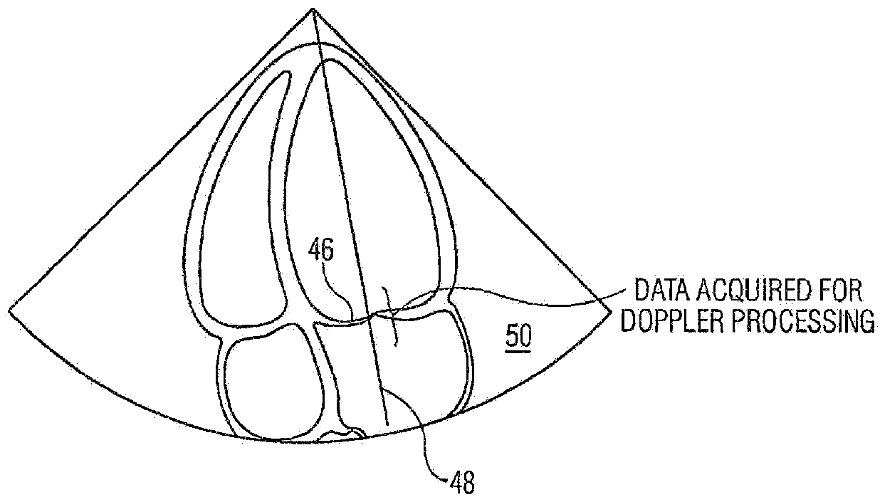
- FIG. 4 shows a mitral valve 46 with a line of acquisition 48 placed automatically. Note that in this case,
- the present invention utilizes ⁇ he concepts data is acquired for an acquisition volume 50 that includes described above to automatically implement the process of the left ventricle and the left atrium to ensure that sufficient collecting a sample volume of spectral Doppler data for data is available for retrospective analysis. Note also that as retrospective analysis. To achieve this s survey system 12 of the heart moves as a function of die heart cycle, the location US 2006/0098853 Al May 11, 2006
- the acquisition volume for Doppler data can be expanded into a conical zone 52 by 5.
- U.S. Pat, No. 6.471,650 B2 which is hereby incorporated by 6-
- a multi-line bundle (for example, 2x2 with a valve in a heart. or 4x4) cover? a finite value of interest around the orifice 46.
- the method of claim 1 wherein the flow indicates a The acquisition would store the received data in such a blood vessel. manner that the phase information is preserved, for instance ⁇ .
- the method of claim 1, wherein the scanning step uses the radio frequency data or basebantied IQ data etc., multi-line beamforming. enabling a flexible retrospective review of the entire acqui9.
- the method of claim 1, wherein the limited region for nisms, methods, and modules described herein can bo impleacquisition is a region selected from the group consisting of mented in hardware, software, or a combination of hardware a 3D pie slice, a cube, an arbitrary shape, and a collection of and software. They may be implemented by any lype of shapes . computer system or other apparatus adapted for carrying out 11.
- ⁇ typical combination of includes adjusting a set of acquisition parameters selected hardware and software could be a general -purpose computer from the group consisting of b-mode line densities, color- system with a computer program that, when loaded and flow line d ⁇ nsitieSj pulse repetition frequency, and ensemble executed, controls the computer system such that k carries length. out the methods described herein.
- An ultrasound system comprising: use computer, containing specialized hardware for carrying out one or more of the functional tasks of the invention could a survey system for collecting motion data from a target be uiOi/ed.
- the present invention can aha be embedded in image; a computer program product, which comprises all the features enabling the implementation of the methods and funca segmentation system for mapping a region of flow tions described herein, and which. — when loaded iii a comw ⁇ trnn the image based on the motion data; and puter system —U able to carry out these methods and a Sow acquisition system that automatically limits the functions Computer program, software program, program, collection of flow image data within the image to the program product, or software, in the present context mean region of flow. any expression, in any language, code notation, of a set 13.
- the ultrasound system of claim 12 wherein the of instructions intended to cause a system having an informotion data comprises color flow data- mation processing capability to perform a particular function 14.
- acquisition system includes a set of acquisition parameters analyzing the motion data to identify a flow in the image; selected from the group consisting of: b-mode line densities, and colorfiow line densities, pufce repetition frequency ; and ensemble length scanning a limited region of the image containing the flow
- An ultrasound system that includes a segmentation with a flow imaging technique. tool for segmenting an image into a flow and a non-flow
- surveying step comregion comprising: prises the step of collecting a sample- of color flow data.
- the ultrasound System of claim 20 further comprising means for collecting grayscale data interspersed with flow a control system that automatically acquires image data from data. the flow region using a flow image technique.
- the program product of claim 28, wherein the collinage technique is selected from the group consisting of: lection of flow data is achieved with a technique selected color flow, time domain correlation, speckle tracking, strain iirorn the group consisting of; color flow, time domain imaging, pulse wave Doppler. and continuous wave Dop- correlalion, speckle tracking, strain imaging, pulse wave pler. Doppler, and continuous wave Doppler.
- An ultrasound method for performing a retrospective control system includes: analysis, comprising: a system for automatically setting a focai ?onc position surveying an image to identify a point of interest; based on a location of the flow region; and a system for automatically setting an image depth based obtaining an acquisition volume of spectral Doppler data upon the location of a peak motion signal wilhin the from the image, wherein the acquisition volume flow region. includes at least one sample volume encompassing the
- spectral Doppler data includes a system that distinguishes plaque from clutter within a phase information; and selected region by analyzing low level echoes and an amount of flow at the selected region. retrospectively analyzing the saved spectral Doppler data.
- a system thai automatically increases an imaging gain at the 33.
- a program product stored on a recordable medium for optimizing ultrasound data comprising: 34.
- means for receiving survey data representative of motion 35.
Abstract
Description


Claims
Priority Applications (5)
| Application Number | Priority Date | Filing Date | Title |
|---|---|---|---|
| JP2010537571A JP2011505951A (en) | 2007-12-13 | 2008-12-08 | Robot ultrasound system with fine adjustment and positioning control using a feedback responsive to the acquired image data |
| US12/747,238 US20100262008A1 (en) | 2007-12-13 | 2008-12-08 | Robotic ultrasound system with microadjustment and positioning control using feedback responsive to acquired image data |
| BRPI0822076A BRPI0822076A8 (en) | 2007-12-13 | 2008-12-08 | IMAGE FORMING SYSTEM, AND METHOD FOR ADJUSTING THE POSITION OF A TRANSDUCER WITH RESPECT TO AN ANATOMICAL STRUCTURE |
| EP08858771A EP2219528A1 (en) | 2007-12-13 | 2008-12-08 | Robotic ultrasound system with microadjustment and positioning control using feedback responsive to acquired image data |
| CN2008801202253A CN101896123A (en) | 2007-12-13 | 2008-12-08 | Robotic ultrasound system with microadjustment and positioning control using feedback responsive to acquired image data |
Applications Claiming Priority (2)
| Application Number | Priority Date | Filing Date | Title |
|---|---|---|---|
| US1333007P | 2007-12-13 | 2007-12-13 | |
| US61/013,330 | 2007-12-13 |
Publications (1)
| Publication Number | Publication Date |
|---|---|
| WO2009074948A1 true WO2009074948A1 (en) | 2009-06-18 |
Family
ID=40459802
Family Applications (1)
| Application Number | Title | Priority Date | Filing Date |
|---|---|---|---|
| PCT/IB2008/055151 WO2009074948A1 (en) | 2007-12-13 | 2008-12-08 | Robotic ultrasound system with microadjustment and positioning control using feedback responsive to acquired image data |
Country Status (6)
| Country | Link |
|---|---|
| US (1) | US20100262008A1 (en) |
| EP (1) | EP2219528A1 (en) |
| JP (1) | JP2011505951A (en) |
| CN (1) | CN101896123A (en) |
| BR (1) | BRPI0822076A8 (en) |
| WO (1) | WO2009074948A1 (en) |
Families Citing this family (44)
| Publication number | Priority date | Publication date | Assignee | Title |
|---|---|---|---|---|
| US8296084B1 (en) * | 2012-01-17 | 2012-10-23 | Robert Hickling | Non-contact, focused, ultrasonic probes for vibrometry, gauging, condition monitoring and feedback control of robots |
| US9198714B2 (en) * | 2012-06-29 | 2015-12-01 | Ethicon Endo-Surgery, Inc. | Haptic feedback devices for surgical robot |
| GB2513884B (en) | 2013-05-08 | 2015-06-17 | Univ Bristol | Method and apparatus for producing an acoustic field |
| JP6192490B2 (en) * | 2013-11-01 | 2017-09-06 | 学校法人中部大学 | Biological blood vessel state measurement device |
| EP3080778B1 (en) | 2013-12-09 | 2019-03-27 | Koninklijke Philips N.V. | Imaging view steering using model-based segmentation |
| US9612658B2 (en) | 2014-01-07 | 2017-04-04 | Ultrahaptics Ip Ltd | Method and apparatus for providing tactile sensations |
| KR102258800B1 (en) * | 2014-05-15 | 2021-05-31 | 삼성메디슨 주식회사 | Ultrasound diagnosis apparatus and mehtod thereof |
| CN106470612B (en) * | 2014-06-30 | 2020-03-24 | 皇家飞利浦有限公司 | Translating an ultrasound array in response to anatomical characterization |
| GB2530036A (en) | 2014-09-09 | 2016-03-16 | Ultrahaptics Ltd | Method and apparatus for modulating haptic feedback |
| MX2017010254A (en) | 2015-02-20 | 2018-03-07 | Ultrahaptics Ip Ltd | Perceptions in a haptic system. |
| MX2017010252A (en) | 2015-02-20 | 2018-03-07 | Ultrahaptics Ip Ltd | Algorithm improvements in a haptic system. |
| US10818162B2 (en) | 2015-07-16 | 2020-10-27 | Ultrahaptics Ip Ltd | Calibration techniques in haptic systems |
| US11189140B2 (en) | 2016-01-05 | 2021-11-30 | Ultrahaptics Ip Ltd | Calibration and detection techniques in haptic systems |
| US10531212B2 (en) | 2016-06-17 | 2020-01-07 | Ultrahaptics Ip Ltd. | Acoustic transducers in haptic systems |
| AU2017294796B2 (en) | 2016-07-15 | 2019-05-30 | Fastbrick Ip Pty Ltd | Brick/block laying machine incorporated in a vehicle |
| AU2017294795B2 (en) | 2016-07-15 | 2019-06-13 | Fastbrick Ip Pty Ltd | Boom for material transport |
| US10268275B2 (en) | 2016-08-03 | 2019-04-23 | Ultrahaptics Ip Ltd | Three-dimensional perceptions in haptic systems |
| US10755538B2 (en) | 2016-08-09 | 2020-08-25 | Ultrahaptics ilP LTD | Metamaterials and acoustic lenses in haptic systems |
| US20180103927A1 (en) * | 2016-10-17 | 2018-04-19 | Neural Analytics, Inc. | Headset and device including a cover |
| US10943578B2 (en) | 2016-12-13 | 2021-03-09 | Ultrahaptics Ip Ltd | Driving techniques for phased-array systems |
| US10497358B2 (en) | 2016-12-23 | 2019-12-03 | Ultrahaptics Ip Ltd | Transducer driver |
| JP6968576B2 (en) * | 2017-05-29 | 2021-11-17 | キヤノンメディカルシステムズ株式会社 | Ultrasonic diagnostic device and ultrasonic diagnostic support device |
| EP3649616A4 (en) | 2017-07-05 | 2021-04-07 | Fastbrick IP Pty Ltd | Real time position and orientation tracker |
| CN111226090B (en) | 2017-08-17 | 2023-05-23 | 快砖知识产权私人有限公司 | Laser tracker with improved roll angle measurement |
| CN111246976B (en) | 2017-08-17 | 2024-03-15 | 快砖知识产权私人有限公司 | Interactive system configuration |
| US20190059850A1 (en) | 2017-08-25 | 2019-02-28 | Neural Analytics, Inc. | Portable headset |
| WO2019071313A1 (en) | 2017-10-11 | 2019-04-18 | Fastbrick Ip Pty Ltd | Machine for conveying objects and multi-bay carousel for use therewith |
| US11531395B2 (en) | 2017-11-26 | 2022-12-20 | Ultrahaptics Ip Ltd | Haptic effects from focused acoustic fields |
| WO2019122916A1 (en) | 2017-12-22 | 2019-06-27 | Ultrahaptics Limited | Minimizing unwanted responses in haptic systems |
| WO2019122912A1 (en) | 2017-12-22 | 2019-06-27 | Ultrahaptics Limited | Tracking in haptic systems |
| CA3098642C (en) | 2018-05-02 | 2022-04-19 | Ultrahaptics Ip Ltd | Blocking plate structure for improved acoustic transmission efficiency |
| US11098951B2 (en) | 2018-09-09 | 2021-08-24 | Ultrahaptics Ip Ltd | Ultrasonic-assisted liquid manipulation |
| EP3628225B1 (en) * | 2018-09-26 | 2021-03-31 | Siemens Healthcare GmbH | Method for recording image data and medical imaging system |
| US11378997B2 (en) | 2018-10-12 | 2022-07-05 | Ultrahaptics Ip Ltd | Variable phase and frequency pulse-width modulation technique |
| CN109480908A (en) * | 2018-12-29 | 2019-03-19 | 无锡祥生医疗科技股份有限公司 | Energy converter air navigation aid and imaging device |
| EP3906462A2 (en) | 2019-01-04 | 2021-11-10 | Ultrahaptics IP Ltd | Mid-air haptic textures |
| CN110025383A (en) * | 2019-02-20 | 2019-07-19 | 广州乔铁医疗科技有限公司 | A kind of robot medicine mirror system with color Doppler ultrasound function |
| US11842517B2 (en) | 2019-04-12 | 2023-12-12 | Ultrahaptics Ip Ltd | Using iterative 3D-model fitting for domain adaptation of a hand-pose-estimation neural network |
| KR20220080737A (en) | 2019-10-13 | 2022-06-14 | 울트라립 리미티드 | Dynamic capping by virtual microphones |
| US11374586B2 (en) | 2019-10-13 | 2022-06-28 | Ultraleap Limited | Reducing harmonic distortion by dithering |
| WO2021090028A1 (en) | 2019-11-08 | 2021-05-14 | Ultraleap Limited | Tracking techniques in haptics systems |
| US11715453B2 (en) | 2019-12-25 | 2023-08-01 | Ultraleap Limited | Acoustic transducer structures |
| US11816267B2 (en) | 2020-06-23 | 2023-11-14 | Ultraleap Limited | Features of airborne ultrasonic fields |
| US11886639B2 (en) | 2020-09-17 | 2024-01-30 | Ultraleap Limited | Ultrahapticons |
Citations (2)
| Publication number | Priority date | Publication date | Assignee | Title |
|---|---|---|---|---|
| US6425865B1 (en) * | 1998-06-12 | 2002-07-30 | The University Of British Columbia | Robotically assisted medical ultrasound |
| US20050154295A1 (en) * | 2003-12-30 | 2005-07-14 | Liposonix, Inc. | Articulating arm for medical procedures |
Family Cites Families (4)
| Publication number | Priority date | Publication date | Assignee | Title |
|---|---|---|---|---|
| DE2826277C2 (en) * | 1978-06-15 | 1980-07-17 | Siemens Ag, 1000 Berlin Und 8000 Muenchen | Device for ultrasonic scanning of objects |
| US5086401A (en) * | 1990-05-11 | 1992-02-04 | International Business Machines Corporation | Image-directed robotic system for precise robotic surgery including redundant consistency checking |
| US8094893B2 (en) * | 2002-12-02 | 2012-01-10 | Koninklijke Philips Electronics N.V. | Segmentation tool for identifying flow regions in an image system |
| EP1804668B1 (en) * | 2004-10-18 | 2012-05-23 | Mobile Robotics Sweden AB | Robot for ultrasonic examination |
-
2008
- 2008-12-08 WO PCT/IB2008/055151 patent/WO2009074948A1/en active Application Filing
- 2008-12-08 BR BRPI0822076A patent/BRPI0822076A8/en not_active IP Right Cessation
- 2008-12-08 JP JP2010537571A patent/JP2011505951A/en not_active Withdrawn
- 2008-12-08 EP EP08858771A patent/EP2219528A1/en not_active Withdrawn
- 2008-12-08 CN CN2008801202253A patent/CN101896123A/en active Pending
- 2008-12-08 US US12/747,238 patent/US20100262008A1/en not_active Abandoned
Patent Citations (2)
| Publication number | Priority date | Publication date | Assignee | Title |
|---|---|---|---|---|
| US6425865B1 (en) * | 1998-06-12 | 2002-07-30 | The University Of British Columbia | Robotically assisted medical ultrasound |
| US20050154295A1 (en) * | 2003-12-30 | 2005-07-14 | Liposonix, Inc. | Articulating arm for medical procedures |
Also Published As
| Publication number | Publication date |
|---|---|
| BRPI0822076A8 (en) | 2016-03-22 |
| BRPI0822076A2 (en) | 2015-06-23 |
| US20100262008A1 (en) | 2010-10-14 |
| CN101896123A (en) | 2010-11-24 |
| JP2011505951A (en) | 2011-03-03 |
| EP2219528A1 (en) | 2010-08-25 |
Similar Documents
| Publication | Publication Date | Title |
|---|---|---|
| WO2009074948A1 (en) | Robotic ultrasound system with microadjustment and positioning control using feedback responsive to acquired image data | |
| US8094893B2 (en) | Segmentation tool for identifying flow regions in an image system | |
| US10835210B2 (en) | Three-dimensional volume of interest in ultrasound imaging | |
| JP7252206B2 (en) | Ultrasound system with deep learning network for image artifact identification and removal | |
| US11006926B2 (en) | Region of interest placement for quantitative ultrasound imaging | |
| EP3563769A1 (en) | Method and ultrasound system for shear wave elasticity imaging | |
| JP2007513726A (en) | Ultrasound imaging system with automatic control of penetration, resolution and frame rate | |
| US20190216423A1 (en) | Ultrasound imaging apparatus and method of controlling the same | |
| CN109310399B (en) | Medical ultrasonic image processing apparatus | |
| US20060004291A1 (en) | Methods and apparatus for visualization of quantitative data on a model | |
| EP3569155A1 (en) | Method and ultrasound system for shear wave elasticity imaging | |
| JP7203823B2 (en) | An ultrasound system that extracts image planes from volume data using touch interaction with the image | |
| CN111683600A (en) | Apparatus and method for obtaining anatomical measurements from ultrasound images | |
| CN111407308A (en) | Ultrasound imaging system and computer-implemented method and medium for optimizing ultrasound images | |
| EP3537981B1 (en) | Ultrasound system for enhanced instrument visualization | |
| JP7061232B6 (en) | Systems and methods for guiding the acquisition of ultrasound images | |
| CN111343925B (en) | Ultrasound shear wave imaging with patient-adaptive shear wave generation | |
| CN112839590A (en) | Method and system for determining a supplemental ultrasound view | |
| US20130018264A1 (en) | Method and system for ultrasound imaging | |
| US20200405264A1 (en) | Region of interest positioning for longitudinal montioring in quantitative ultrasound | |
| CN112168210A (en) | Medical image processing terminal, ultrasonic diagnostic equipment and fetal image processing method | |
| EP3875036A1 (en) | Ultrasonic imaging apparatus and method of controlling the same | |
| US11810294B2 (en) | Ultrasound imaging system and method for detecting acoustic shadowing | |
| EP3685753A1 (en) | Ultrasound imaging apparatus and method of controlling the same |
Legal Events
| Date | Code | Title | Description |
|---|---|---|---|
| WWE | Wipo information: entry into national phase |
Ref document number: 200880120225.3 Country of ref document: CN |
|
| 121 | Ep: the epo has been informed by wipo that ep was designated in this application |
Ref document number: 08858771 Country of ref document: EP Kind code of ref document: A1 |
|
| WWE | Wipo information: entry into national phase |
Ref document number: 2008858771 Country of ref document: EP |
|
| WWE | Wipo information: entry into national phase |
Ref document number: 2010537571 Country of ref document: JP |
|
| WWE | Wipo information: entry into national phase |
Ref document number: 12747238 Country of ref document: US |
|
| NENP | Non-entry into the national phase |
Ref country code: DE |
|
| WWE | Wipo information: entry into national phase |
Ref document number: 4233/CHENP/2010 Country of ref document: IN |
|
| WWE | Wipo information: entry into national phase |
Ref document number: 2010128944 Country of ref document: RU |
|
| ENP | Entry into the national phase |
Ref document number: PI0822076 Country of ref document: BR Kind code of ref document: A2 Effective date: 20100610 |