WO2008046531A1 - Enhanced coding and parameter representation of multichannel downmixed object coding - Google Patents
Enhanced coding and parameter representation of multichannel downmixed object coding Download PDFInfo
- Publication number
- WO2008046531A1 WO2008046531A1 PCT/EP2007/008683 EP2007008683W WO2008046531A1 WO 2008046531 A1 WO2008046531 A1 WO 2008046531A1 EP 2007008683 W EP2007008683 W EP 2007008683W WO 2008046531 A1 WO2008046531 A1 WO 2008046531A1
- Authority
- WO
- WIPO (PCT)
- Prior art keywords
- audio
- downmix
- matrix
- parameters
- channels
- Prior art date
Links
- 239000011159 matrix material Substances 0.000 claims description 237
- 238000009877 rendering Methods 0.000 claims description 80
- 238000000034 method Methods 0.000 claims description 39
- 238000006243 chemical reaction Methods 0.000 claims description 28
- 230000015572 biosynthetic process Effects 0.000 claims description 6
- 238000004590 computer program Methods 0.000 claims description 6
- 230000005236 sound signal Effects 0.000 claims description 4
- 230000000694 effects Effects 0.000 claims description 3
- 239000008186 active pharmaceutical agent Substances 0.000 claims description 2
- 238000013144 data compression Methods 0.000 claims description 2
- 238000007781 pre-processing Methods 0.000 claims description 2
- 230000002194 synthesizing effect Effects 0.000 claims description 2
- 108091006146 Channels Proteins 0.000 description 162
- 230000000875 corresponding effect Effects 0.000 description 10
- 239000000203 mixture Substances 0.000 description 9
- 238000004364 calculation method Methods 0.000 description 7
- 230000005540 biological transmission Effects 0.000 description 5
- 238000003786 synthesis reaction Methods 0.000 description 5
- 238000000926 separation method Methods 0.000 description 4
- 238000013461 design Methods 0.000 description 3
- 238000012545 processing Methods 0.000 description 3
- 238000004422 calculation algorithm Methods 0.000 description 2
- 238000009795 derivation Methods 0.000 description 2
- 239000000284 extract Substances 0.000 description 2
- 238000001914 filtration Methods 0.000 description 2
- 238000012986 modification Methods 0.000 description 2
- 230000004048 modification Effects 0.000 description 2
- 238000005070 sampling Methods 0.000 description 2
- 101100067993 Saccharomyces cerevisiae (strain ATCC 204508 / S288c) ASC1 gene Proteins 0.000 description 1
- 101100067991 Schizosaccharomyces pombe (strain 972 / ATCC 24843) rkp1 gene Proteins 0.000 description 1
- 230000003213 activating effect Effects 0.000 description 1
- 238000004458 analytical method Methods 0.000 description 1
- 230000002301 combined effect Effects 0.000 description 1
- 238000007906 compression Methods 0.000 description 1
- 230000006835 compression Effects 0.000 description 1
- 230000002596 correlated effect Effects 0.000 description 1
- 230000003111 delayed effect Effects 0.000 description 1
- 238000011161 development Methods 0.000 description 1
- 238000003780 insertion Methods 0.000 description 1
- 230000037431 insertion Effects 0.000 description 1
- 229940050561 matrix product Drugs 0.000 description 1
- 238000005259 measurement Methods 0.000 description 1
- 238000010606 normalization Methods 0.000 description 1
- 238000012805 post-processing Methods 0.000 description 1
Classifications
-
- G—PHYSICS
- G10—MUSICAL INSTRUMENTS; ACOUSTICS
- G10L—SPEECH ANALYSIS TECHNIQUES OR SPEECH SYNTHESIS; SPEECH RECOGNITION; SPEECH OR VOICE PROCESSING TECHNIQUES; SPEECH OR AUDIO CODING OR DECODING
- G10L19/00—Speech or audio signals analysis-synthesis techniques for redundancy reduction, e.g. in vocoders; Coding or decoding of speech or audio signals, using source filter models or psychoacoustic analysis
- G10L19/04—Speech or audio signals analysis-synthesis techniques for redundancy reduction, e.g. in vocoders; Coding or decoding of speech or audio signals, using source filter models or psychoacoustic analysis using predictive techniques
- G10L19/16—Vocoder architecture
- G10L19/18—Vocoders using multiple modes
- G10L19/20—Vocoders using multiple modes using sound class specific coding, hybrid encoders or object based coding
-
- G—PHYSICS
- G10—MUSICAL INSTRUMENTS; ACOUSTICS
- G10L—SPEECH ANALYSIS TECHNIQUES OR SPEECH SYNTHESIS; SPEECH RECOGNITION; SPEECH OR VOICE PROCESSING TECHNIQUES; SPEECH OR AUDIO CODING OR DECODING
- G10L19/00—Speech or audio signals analysis-synthesis techniques for redundancy reduction, e.g. in vocoders; Coding or decoding of speech or audio signals, using source filter models or psychoacoustic analysis
- G10L19/008—Multichannel audio signal coding or decoding using interchannel correlation to reduce redundancy, e.g. joint-stereo, intensity-coding or matrixing
-
- G—PHYSICS
- G10—MUSICAL INSTRUMENTS; ACOUSTICS
- G10L—SPEECH ANALYSIS TECHNIQUES OR SPEECH SYNTHESIS; SPEECH RECOGNITION; SPEECH OR VOICE PROCESSING TECHNIQUES; SPEECH OR AUDIO CODING OR DECODING
- G10L19/00—Speech or audio signals analysis-synthesis techniques for redundancy reduction, e.g. in vocoders; Coding or decoding of speech or audio signals, using source filter models or psychoacoustic analysis
- G10L19/04—Speech or audio signals analysis-synthesis techniques for redundancy reduction, e.g. in vocoders; Coding or decoding of speech or audio signals, using source filter models or psychoacoustic analysis using predictive techniques
- G10L19/16—Vocoder architecture
- G10L19/173—Transcoding, i.e. converting between two coded representations avoiding cascaded coding-decoding
-
- H—ELECTRICITY
- H04—ELECTRIC COMMUNICATION TECHNIQUE
- H04S—STEREOPHONIC SYSTEMS
- H04S3/00—Systems employing more than two channels, e.g. quadraphonic
- H04S3/008—Systems employing more than two channels, e.g. quadraphonic in which the audio signals are in digital form, i.e. employing more than two discrete digital channels
-
- H—ELECTRICITY
- H04—ELECTRIC COMMUNICATION TECHNIQUE
- H04S—STEREOPHONIC SYSTEMS
- H04S3/00—Systems employing more than two channels, e.g. quadraphonic
- H04S3/02—Systems employing more than two channels, e.g. quadraphonic of the matrix type, i.e. in which input signals are combined algebraically, e.g. after having been phase shifted with respect to each other
-
- H—ELECTRICITY
- H04—ELECTRIC COMMUNICATION TECHNIQUE
- H04S—STEREOPHONIC SYSTEMS
- H04S7/00—Indicating arrangements; Control arrangements, e.g. balance control
- H04S7/30—Control circuits for electronic adaptation of the sound field
-
- H—ELECTRICITY
- H04—ELECTRIC COMMUNICATION TECHNIQUE
- H04S—STEREOPHONIC SYSTEMS
- H04S2400/00—Details of stereophonic systems covered by H04S but not provided for in its groups
- H04S2400/03—Aspects of down-mixing multi-channel audio to configurations with lower numbers of playback channels, e.g. 7.1 -> 5.1
-
- H—ELECTRICITY
- H04—ELECTRIC COMMUNICATION TECHNIQUE
- H04S—STEREOPHONIC SYSTEMS
- H04S2400/00—Details of stereophonic systems covered by H04S but not provided for in its groups
- H04S2400/11—Positioning of individual sound objects, e.g. moving airplane, within a sound field
-
- H—ELECTRICITY
- H04—ELECTRIC COMMUNICATION TECHNIQUE
- H04S—STEREOPHONIC SYSTEMS
- H04S2420/00—Techniques used stereophonic systems covered by H04S but not provided for in its groups
- H04S2420/03—Application of parametric coding in stereophonic audio systems
-
- H—ELECTRICITY
- H04—ELECTRIC COMMUNICATION TECHNIQUE
- H04S—STEREOPHONIC SYSTEMS
- H04S5/00—Pseudo-stereo systems, e.g. in which additional channel signals are derived from monophonic signals by means of phase shifting, time delay or reverberation
Definitions
- the present invention relates to decoding of multiple objects from an encoded multi-object signal based on an available multichannel downmix and additional control data.
- a parametric multi-channel audio decoder (e.g. the MPEG Surround decoder defined in ISO/ESC 23003-1 [1], [2]), reconstructs M channels based on K transmitted channels, where M > K, by use of the additional control data.
- the control data consists of a parameterisation of the multi-channel signal based on HD (Inter channel Intensity Difference) and ICC (Inter Channel Coherence).
- HD Inter channel Intensity Difference
- ICC Inter Channel Coherence
- a much related coding system is the corresponding audio object coder [3], [4] where several audio objects are downmixed at the encoder and later on upmixed guided by control data.
- the process of upmixing can be also seen as a separation of the objects that are mixed in the downmix.
- the resulting upmixed signal can be rendered into one or more playback channels.
- [3,4] presents a method to synthesize audio channels from a downmix (referred to as sum signal), statistical informa- tion about the source objects, and data that describes the desired output format.
- sum signal referred to as sum signal
- these downmix signals consist of different subsets of the objects, and the upmixing is performed for each downmix channel individually.
- a first aspect of the invention relates to an audio object coder for generating an encoded audio object signal using a plurality of audio objects, comprising: a downmix information generator for generating downmix information indicating a distribution of the plurality of audio objects into at least two down- mix channels; an object parameter generator for generating object parameters for the audio objects; and an output interface for generating the encoded audio object signal using the downmix information and the object parameters.
- a second aspect of the invention relates to an audio object coding method for generating an encoded audio object signal using a plurality of audio objects, comprising: generating downmix information indicating a distribution of the plurality of audio objects into at least two downmix channels; generat- ing object parameters for the audio objects; and generating the encoded audio object signal using the downmix information and the object parameters.
- a third aspect of the invention relates to an audio synthesizer for generating output data using an encoded audio object signal, comprising: an output data synthesizer for generating the output data usable for creating a plurality of output channels of a predefined audio output configuration representing the plurality of audio objects, the output data synthesizer being operative to use downmix information indicating a distribution of the plurality of audio objects into at least two downmix channels, and audio object parameters for the audio objects.
- a fourth aspect of the invention relates to an audio synthesizing method for generating output data using an encoded audio object signal, comprising: generating the output data usable for creating a plurality of output channels of a predefined audio output configuration representing the plurality of audio objects, the output data synthesizer being operative to use downmix information indicating a distribution of the plurality of audio objects into at least two downmix channels, and audio object parameters for the audio objects.
- a fifth aspect of the invention relates to an encoded audio object signal including a downmix informa- tion indicating a distribution of a plurality of audio objects into at least two downmix channels and object parameters, the object parameters being such that the reconstruction of the audio objects is possible using the object parameters and the at least two downmix channels.
- a sixth aspect of the invention relates to a computer program for performing, when running on a computer, the audio object coding method or the audio object decoding method.
- Fig. Ia illustrates the operation of spatial audio object coding comprising encoding and decoding
- Fig. Ib illustrates the operation of spatial audio object coding reusing an MPEG Surround de- coder
- Fig. 2 illustrates the operation of a spatial audio object encoder
- Fig. 3 illustrates an audio object parameter extractor operating in energy based mode
- Fig. 4 illustrates an audio object parameter extractor operating in prediction based mode
- Fig. 5 illustrates the structure of an SAOC to MPEG Surround transcoder
- FFiigg.. 66 illustrates different operation modes of a downmix converter
- Fig. 7 illustrates the structure of an MPEG Surround decoder for a stereo downmix
- Fig. 8 illustrates a practical use case including an SAOC encoder
- Fig. 9 illustrates an encoder embodiment
- Fig. 10 illustrates a decoder embodiment
- FFiigg.. 1111 illustrates a table for showing different preferred decoder/synthesizer modes
- Fig. 12 illustrates a method for calculating certain spatial upmix parameters
- Fig. 13a illustrates a method for calculating additional spatial upmix parameters
- Fig. 13b illustrates a method for calculating using prediction parameters
- Fig. 14 illustrates a general overview of an encoder/decoder system
- Fig. 15 illustrates a method of calculating prediction object parameters
- Fig. 16 illustrates a method of stereo rendering.
- Preferred embodiments provide a coding scheme that combines the functionality of an object coding scheme with the rendering capabilities of a multi-channel decoder.
- the transmitted control data is related to the individual objects and allows therefore a manipulation in the reproduction in terms of spatial position and level.
- the control data is directly related to the so called scene description, giving information on the positioning of the objects.
- the scene description can be either controlled on the decoder side interactively by the listener or also on the encoder side by the producer.
- a transcoder stage as taught by the invention is used to convert the object related control data and downmix signal into control data and a downmix signal that is related to the reproduction system, as e.g. the MPEG Surround decoder.
- the objects can be arbitrarily distributed in the available downmix channels at the encoder.
- the transcoder makes explicit use of the multichannel downmix information, providing a transcoded downmix signal and object related control data.
- the upmixing at the decoder is not done for all channels individually as proposed in [3], but all downmix channels are treated at the same time in one single upmixing process.
- the multichannel downmix information has to be part of the control data and is encoded by the object encoder.
- the distribution of the objects into the downmix channels can be done in an automatic way or it can be a design choice on the encoder side. In the latter case one can design the downmix to be suitable for playback by an existing multi-channel reproduction scheme (e.g., Stereo reproduction system), featuring a reproduction and omitting the transcoding and multi-channel decoding stage.
- an existing multi-channel reproduction scheme e.g., Stereo reproduction system
- object coding schemes of prior art solely describe the decoding process using a single downmix channel, the present invention does not suffer from this limitation as it supplies a method to jointly decode downmixes containing more than one channel downmix.
- the obtainable quality in the separa- tion of objects increases by an increased number of downmix channels.
- the invention successfully bridges the gap between an object coding scheme with a single mono downmix channel and multi-channel coding scheme where each object is transmitted in a separate channel.
- the proposed scheme thus allows flexible scaling of quality for the separation of objects according to requirements of the application and the properties of the transmission system (such as the channel capacity).
- a system for transmitting and creating a plurality of individual audio objects using a multi-channel downmix and additional control data describing the objects comprising: a spatial audio object encoder for encoding a plurality of audio objects into a multichannel downmix, information about the multichannel downmix, and object parameters; or a spatial audio object decoder for decoding a mul- tichannel downmix, information about the multichannel downmix, object parameters, and an object rendering matrix into a second multichannel audio signal suitable for audio reproduction.
- Fig. Ia illustrates the operation of spatial audio object coding (SAOC), comprising an SAOC encoder 101 and an SAOC decoder 104.
- the spatial audio object encoder 101 encodes N objects into an ob- ject downmix consisting of K > 1 audio channels, according to encoder parameters.
- Information about the applied downmix weight matrix D is output by the SAOC encoder together with optional data concerning the power and correlation of the downmix.
- the matrix D is often, but not necessarily always, constant over time and frequency, and therefore represents a relatively low amount of information.
- the SAOC encoder extracts object parameters for each object as a function of both time and frequency at a resolution defined by perceptual considerations.
- the spatial audio object decoder 104 takes the object downmix channels, the downmix info, and the object parameters (as generated by the encoder) as input and generates an output with M audio channels for presentation to the user.
- the rendering of N objects into M audio channels makes use of a rendering matrix provided as user input to the SAOC decoder.
- Fig. Ib illustrates the operation of spatial audio object coding reusing an MPEG Surround decoder.
- An SAOC decoder 104 taught by the current invention can be realized as an SAOC to MPEG Surround transcoder 102 and an stereo downmix based MPEG Surround decoder 103.
- the task of the SAOC decoder is to perceptually recreate the target rendering of the original audio objects.
- the SAOC to MPEG Surround transcoder 102 takes as input the rendering matrix A , the object downmix, the downmix side information including the downmix weight matrix D , and the object side information, and generates a stereo downmix and MPEG Surround side information.
- a subsequent MPEG Surround decoder 103 fed with this data will produce an M channel audio output with the desired properties.
- An SAOC decoder taught by the current invention consists of an SAOC to MPEG Surround transcoder 102 and an stereo downmix based MPEG Surround decoder 103.
- the task of the SAOC decoder is to perceptually recreate the target rendering of the original audio objects.
- the SAOC to MPEG Surround transcoder 102 takes as input the rendering matrix A , the object downmix, the downmix side information including the downmix weight matrix D , and the object side information, and generates a stereo downmix and MPEG Surround side information.
- a subsequent MPEG Surround decoder 103 fed with this data will produce an M channel audio output with the desired properties.
- Fig. 2 illustrates the operation of a spatial audio object (SAOC) encoder 101 taught by current invention.
- the N audio objects are fed both into a downmixer 201 and an audio object parameter extractor 202.
- the downmixer 201 mixes the objects into an object downmix consisting of K > 1 audio channels, according to the encoder parameters and also outputs downmix information.
- This information includes a description of the applied downmix weight matrix D and, optionally, if the subsequent audio object parameter extractor operates in prediction mode, parameters describing the power and correlation of the object downmix.
- the audio object parameter extractor 202 extracts object parameters according to the encoder parameters.
- the encoder control determines on a time and frequency varying basis which one of two encoder modes is applied, the energy based or the prediction based mode. In the energy based mode, the encoder parameters further contains information on a grouping of the N audio objects into .P stereo objects and N-2Pmono objects. Each mode will be further described by Figures 3 and 4.
- Fig. 3 illustrates an audio object parameter extractor 202 operating in energy based mode.
- a grouping 301 into P stereo objects and N-2P mono objects is performed according to grouping information contained in the encoder parameters. For each considered time frequency interval the following operations are then performed.
- Two object powers and one normalized correlation are extracted for each of the P stereo objects by the stereo parameter extractor 302.
- One power parameter is extracted for each of the N -IP mono obj ects by the mono parameter extractor 303.
- the total set of N power parameters and P normalized correlation parameters is then encoded in 304 together with the grouping data to form the object parameters.
- the encoding can contain a normalization step with respect to the largest object power or with respect to the sum of extracted object powers.
- Fig. 4 illustrates an audio object parameter extractor 202 operating in prediction based mode. For each considered time frequency interval the following operations are performed. For each of the N objects, a linear combination of the K object downmix channels is derived which matches the given object in a least squares sense. The K weights of this linear combination are called Object Prediction Coefficients (OPC) and they are computed by the OPC extractor 401. The total set of N K OPCs are encoded in 402 to form the object parameters. The encoding can incorporate a reduction of total number of OPCs based on linear interdependencies. As taught by the present invention, this total number can be reduced to max [K • (N - K), 0 ⁇ if the downmix weight matrix D has full rank.
- OPC Object Prediction Coefficients
- Fig. 5 illustrates the structure of an SAOC to MPEG Surround transcoder 102 as taught by the current invention.
- the downmix side information and the object parameters are combined with the rendering matrix by the parameter calculator 502 to form MPEG Surround parameters of type CLD, CPC, and ICC, and a downmix converter matrix G of size 2x AT .
- the downmix converter 501 converts the object downmix into a stereo downmix by applying a matrix operation according to the G matrices.
- this matrix is the identity matrix and the object downmix is passed unaltered through as stereo downmix.
- This mode is illustrated in the drawing with the selector switch 503 in position A, whereas the normal operation mode has the switch in position B.
- An additional advantage of the transcoder is its usability as a stand alone application where the MPEG Surround parameters are ignored and the output of the downmix converter is used directly as a stereo rendering.
- Fig. 6 illustrates different operation modes of a downmix converter 501 as taught by the present invention.
- this bitstream is first decoded by the audio decoder 601 into K time domain audio signals. These signals are then all transformed to the frequency domain by an MPEG Surround hybrid QMF filter bank in the T/F unit 602.
- the time and frequency varying matrix operation defined by the converter matrix data is performed on the resulting hybrid QMF domain signals by the matrixing unit 603 which outputs a stereo signal in the hybrid QMF domain.
- the hybrid synthesis unit 604 converts the stereo hybrid QMF domain signal into a stereo QMF domain signal.
- the hybrid QMF domain is defined in order to obtain better frequency resolution towards lower frequencies by means of a subsequent filtering of the QMF subbands.
- this subsequent filtering is defined by banks of Nyquist filters
- the conversion from the hybrid to the standard QMF domain consists of simply summing groups of hybrid subband signals, see [E. Schuijers, J. Breebart, and H. Purnhagen "Low complexity parametric stereo coding" Proc 116 th AES convention Berlin .Germany 2004, Preprint 6073].
- This signal constitutes the first possible output format of the downmix converter as defined by the selector switch 607 in position A.
- Such a QMF domain signal can be fed directly into the corresponding QMF domain interface of an MPEG Surround decoder, and this is the most advantageous operation mode in terms of delay, complexity and quality.
- the next possibility is obtained by performing a QMF filter bank synthesis 605 in order to obtain a stereo time domain signal. With the selector switch 607 in position B the converter outputs a digital audio stereo signal that also can be fed into the time domain interface of a subsequent MPEG Surround decoder, or rendered directly in a stereo playback device.
- the third possibility with the selector switch 607 in position C is obtained by encoding the time domain stereo signal with a stereo audio encoder 606.
- the output format of the downmix converter is then a stereo audio bitstream which is compatible with a core decoder contained in the MPEG decoder.
- This third mode of operation is suitable for the case where the SAOC to MPEG Surround transcoder is separated by the MPEG decoder by a connection that imposes restrictions on bitrate, or in the case where the user desires to store a particular object rendering for future playback.
- Fig 7 illustrates the structure of an MPEG Surround decoder for a stereo downmix.
- the stereo down- mix is converted to three intermediate channels by the Two-To-Three (TTT) box. These intermediate channels are further split into two by the three One-To-Two (OTT) boxes to yield the six channels of a 5.1 channel configuration.
- Fig. 8 illustrates a practical use case including an SAOC encoder.
- An audio mixer 802 outputs a stereo signal (L and R) which typically is composed by combining mixer input signals (here input channels 1-6) and optionally additional inputs from effect returns such as reverb etc.
- the mixer also outputs an individual channel (here channel 5) from the mixer. This could be done e.g.
- the stereo signal (L and R) and the individual channel output (obj5) are input to the SAOC encoder 801, which is nothing but a special case of the SAOC encoder 101 in Fig. 1.
- the audio object obj5 containing e.g. speech
- the stereo mix could be extended by an multichannel mix such as a 5.1 -mix.
- y(k) denotes the complex conjugate signal of y(k) .
- All signals considered here are subband samples from a modulated filter bank or windowed FFT analysis of discrete time signals. It is understood that these subbands have to be transformed back to the discrete time domain by corresponding synthesis filter bank operations.
- a signal block of Z samples represents the signal in a time and frequency interval which is a part of the perceptually motivated tiling of the time-frequency plane which is applied for the description of signal properties.
- the given audio objects can be represented as N rows of length Z in a matrix
- the downmix weight matrix D of size Kx N where K > 1 determines the K channel downmix signal in the form of a matrix with K rows through the matrix multiplication
- the user controlled object rendering matrix A of size Mx N determines the M channel target rendering of the audio objects in the form of a matrix with M rows through the matrix multiplication
- the task of the SAOC decoder is to generate an approximation in the perceptual sense of the target rendering Y of the original audio objects, given the rendering matrix A ,the downmix X the downmix matrix D , and object parameters.
- the object parameters in the energy mode taught by the present invention carry information about the covariance of the original objects.
- this covariance is given in un-normalized form by the matrix product SS * where the star denotes the complex conjugate transpose matrix operation.
- energy mode object parameters furnish a positive semi-definite Nx N matrix E such that, possibly up to a scale factor,
- the object parameters in the prediction mode taught by the present invention aim at making an Nx K object prediction coefficient (OPC) matrix C available to the decoder such that
- the OPC extractor 401 solves the normal equations
- I is the identity matrix of size AT .
- D has full rank it follows by elementary linear algebra that the set of solutions to (9) can be parameterized by max [K-(N-K), 0 ⁇ parameters. This is exploited in the joint encoding in 402 of the OPC data.
- the downmix matrix is
- the object parameters can be in both energy or prediction mode, but the transcoder should preferably operate in prediction mode. If the downmix audio coder is not a waveform coder the in the considered frequency interval, the object encoder and the and the transcoder should both operate in energy mode.
- the fourth combination is of less relevance so the subsequent description will address the first three combinations only.
- the data available to the transcoder is described by the triplet of matrices (D, E, A) .
- the MPEG Surround OTT parameters are obtained by performing energy and correlation estimates on a virtual rendering derived from the transmitted parameters and the 6 x N rendering matrix A .
- the six channel target covariance is given by
- the target rendering thus consists of placing object 1 between right front and right surround, object 2 between left front and left surround, and object 3 in both right front, center, and lfe. Assume also for simplicity that the three objects are uncorrelated and all have the same energy such that
- the MPEG surround decoder will be instructed to use some decorrelation between right front and right surround but no decorrelation between left front and left surround.
- Such a matrix is preferably derived by considering first the normal equations
- the matrix C 3 contains the best weights for obtaining an approximation to the desired object rendering to the combined channels (l,r,qc) from the object downmix.
- This general type of matrix operation cannot be implemented by the MPEG surround decoder, which is tied to a limited space of TTT matrices through the use of only two parameters.
- the object of the inventive downmix converter is to pre-process the object downmix such that the combined effect of the pre-processing and the MPEG Surround TTT matrix is identical to the desired upmix described by C 3 .
- the TTT matrix for prediction of (l,r,qc) from (Z 0 , r 0 ) is parameterized by three parameters [a, ⁇ , ⁇ ) via
- the available data is represented by the matrix triplet (D, C, A) where C is the Nx 2 matrix holding the N pairs of OPCs. Due to the relative nature of prediction coefficients, it will further be necessary for the estimation of energy based MPEG Surround parameters to have access to an approximation to the 2x 2 covariance matrix of the object downmix,
- This information is preferably transmitted from the object encoder as part of the downmix side infor- mation, but it could also be estimated at the transcoder from measurements performed on the received downmix, or indirectly derived from (D, C) by approximate object model considerations.
- the object to stereo downmix converter 501 outputs an approximation to a stereo downmix of the 5.1 channel rendering of the audio objects.
- this downmix is interesting in its own right and a direct manipulation of the stereo rendering A 2 is attractive.
- a user control of the voice volume can be realized by the rendering where v is the voice to music quotient control.
- the design of the downmix converter matrix is based on
- Fig. 9 illustrates a preferred embodiment of an audio object coder in accordance with one aspect of the present invention.
- the audio object encoder 101 has already been generally described in connection with the preceding figures.
- the audio object coder for generating the encoded object signal uses the plurality of audio objects 90 which have been indicated in Fig. 9 as entering a downmixer 92 and an object parameter generator 94.
- the audio object encoder 101 includes the downmix information generator 96 for generating downmix information 97 indicating a distribution of the plurality of audio objects into at least two downmix channels indicated at 93 as leaving the downmixer 92.
- the object parameter generator is for generating object parameters 95 for the audio objects, wherein the object parameters are calculated such that the reconstruction of the audio object is possible using the object parameters and at least two downmix channels 93. Importantly, however, this reconstruction does not take place on the encoder side, but takes place on the decoder side. Nevertheless, the encoder- side object parameter generator calculates the object parameters for the objects 95 so that this full reconstruction can be performed on the decoder side. Furthermore, the audio object encoder 101 includes an output interface 98 for generating the encoded audio object signal 99 using the downmix information 97 and the object parameters 95. Depending on the application, the downmix channels 93 can also be used and encoded into the encoded audio object signal.
- the output interface 98 generates an encoded audio object signal 99 which does not include the downmix channels.
- This situation may arise when any downmix channels to be used on the decoder side are already at the decoder side, so that the downmix information and the object parameters for the audio objects are transmitted separately from the downmix channels.
- Such a situation is useful when the object downmix channels 93 can be pur- chased separately from the object parameters and the downmix information for a smaller amount of money, and the object parameters and the downmix information can be purchased for an additional amount of money in order to provide the user on the decoder side with an added value.
- the object parameters and the downmix information enable the user to form a flexible rendering of the audio objects at any intended audio reproduction setup, such as a stereo system, a multi-channel sys- tem or even a wave field synthesis system. While wave field synthesis systems are not yet very popular, multi-channel systems such as 5.1 systems or 7.1 systems are becoming increasingly popular on the consumer market.
- Fig. 10 illustrates an audio synthesizer for generating output data.
- the audio synthesizer includes an output data synthesizer 100.
- the output data synthesizer receives, as an input, the down- mix information 97 and audio object parameters 95 and, probably, intended audio source data such as a positioning of the audio sources or a user-specified volume of a specific source, which the source should have been when rendered as indicated at 101.
- the output data synthesizer 100 is for generating output data usable for creating a plurality of output channels of a predefined audio output configuration representing a plurality of audio objects. Particularly, the output data synthesizer 100 is operative to use the downmix information 97, and the audio object parameters 95. As discussed in connection with Fig. 11 later on, the output data can be data of a large variety of different useful applications, which include the specific rendering of output channels or which include just a reconstruction of the source signals or which include a transcoding of parameters into spatial rendering parameters for a spatial upmixer configuration without any specific rendering of output channels, but e.g. for storing or transmitting such spatial parameters.
- the general application scenario of the present invention is summarized in Fig. 14.
- an encoder side 140 which includes the audio object encoder 101 which receives, as an input, N audio objects.
- the output of the preferred audio object encoder comprises, in addition to the downmix information and the object parameters which are not shown in Fig. 14, the K downmix channels.
- the number of downmix channels in accordance with the present invention is greater than or equal to two.
- the downmix channels are transmitted to a decoder side 142, which includes a spatial upmixer 143.
- the spatial upmixer 143 may include the inventive audio synthesizer, when the audio synthesizer is operated in a transcoder mode. When the audio synthesizer 101 as illustrated in Fig. 10, however, works in a spatial upmixer mode, then the spatial upmixer 143 and the audio synthesizer are the same device in this embodiment.
- the spatial upmixer generates M output channels to be played via M speakers. These speakers are positioned at predefined spatial locations and together represent the predefined audio output configuration.
- An output channel of the predefined audio output configuration may be seen as a digital or analog speaker signal to be sent from an output of the spatial upmixer 143 to the input of a loudspeaker at a predefined position among the plurality of predefined positions of the predefined audio output configuration.
- the number of M output channels can be equal to two when stereo rendering is performed.
- the number of M output channels is larger than two.
- M is larger than K and may even be much larger than K, such as double the size or even more.
- Fig. 14 furthermore includes several matrix notations in order to illustrate the functionality of the inventive encoder side and the inventive decoder side.
- blocks of sampling values are proc- essed. Therefore, as is indicated in equation (2), an audio object is represented as a line of L sampling values.
- the matrix S has N lines corresponding to the number of objects and L columns corresponding to the number of samples.
- the matrix E is calculated as indicated in equation (5) and has N columns and N lines.
- the matrix E includes the object parameters when the object parameters are given in the energy mode.
- the matrix E has, as indicated before in connection with equa- tion (6) only main diagonal elements, wherein a main diagonal element gives the energy of an audio object. All off-diagonal elements represent, as indicated before, a correlation of two audio objects, which is specifically useful when some objects are two channels of the stereo signal.
- equation (2) is a time domain signal. Then a single energy value for the whole band of audio objects is generated.
- the audio objects are processed by a time/frequency converter which includes, for example, a type of a transform or a filter bank algorithm.
- equation (2) is valid for each subband so that one obtains a matrix E for each subband and, of course, each time frame.
- the downmix channel matrix X has K lines and L columns and is calculated as indicated in equation (3).
- the M output channels are calculated using the N objects by applying the so-called rendering matrix A to the N objects.
- the N objects can be regenerated on the decoder side using the downmix and the object parameters and the rendering can be applied to the reconstructed object signals directly.
- the downmix can be directly transformed to the output channels without an explicit calculation of the source signals.
- the rendering matrix A indicates the positioning of the indi- vidual sources with respect to the predefined audio output configuration. If one had six objects and six output channels, then one could place each object at each output channel and the rendering matrix would reflect this scheme. If, however, one would like to place all objects between two output speaker locations, then the rendering matrix A would look different and would reflect this different situation.
- the rendering matrix or, more generally stated, the intended positioning of the objects and also an intended relative volume of the audio sources can in general be calculated by an encoder and transmitted to the decoder as a so-called scene description.
- this scene description can be generated by the user herself/himself for generating the user-specific upmix for the user- specific audio output configuration.
- a transmission of the scene description is, therefore, not necessar- ily required, but the scene description can also be generated by the user in order to fulfill the wishes of the user.
- the user might, for example, like to place certain audio objects at places which are different from the places where these objects were when generating these objects.
- the audio objects are designed by themselves and do not have any "original" location with respect to the other objects. In this situation, the relative location of the audio sources is generated by the user at the first time.
- a downmixer 92 is illustrated.
- the downmixer is for downmixing the plurality of audio objects into the plurality of downmix channels, wherein the number of audio objects is larger than the number of downmix channels, and wherein the downmixer is coupled to the downmix infor- mation generator so that the distribution of the plurality of audio objects into the plurality of downmix channels is conducted as indicated in the downmix information.
- the downmix information generated by the downmix information generator 96 in Fig. 9 can be automatically created or manually adjusted. It is preferred to provide the downmix information with a resolution smaller than the resolution of the object parameters.
- the downmix information represents a downmix matrix having K lines and N columns.
- the value in a line of the downmix matrix has a certain value when the audio object corresponding to this value in the downmix matrix is in the downmix channel represented by the row of the downmix matrix.
- the values of more than one row of the downmix matrix have a certain value.
- audio objects can be input into one or more downmix channels with varying levels, and these levels can be indicated by weights in the downmix matrix which are different from one and which do not add up to 1.0 for a certain audio object.
- the encoded audio object signal may be for example a time-multiplex signal in a certain format.
- the encoded audio object signal can be any signal which allows the separation of the object parameters 95, the downmix information 97 and the downmix channels 93 on a decoder side.
- the output interface 98 can include encoders for the object parameters, the downmix information or the downmix channels. Encoders for the object parameters and the downmix information may be differential encoders and/or entropy encoders, and encoders for the downmix channels can be mono or stereo audio encoders such as MP3 encoders or AAC encoders. All these encoding operations result in a further data compression in order to further decrease the data rate required for the encoded audio object signal 99.
- the downmixer 92 is operative to include the stereo representation of background music into the at least two downmix channels and furthermore introduces the voice track into the at least two downmix channels in a predefined ratio.
- a first channel of the background music is within the first downmix channel and the second channel of the back- ground music is within the second downmix channel. This results in an optimum replay of the stereo background music on a stereo rendering device. The user can, however, still modify the position of the voice track between the left stereo speaker and the right stereo speaker.
- the first and the second background music channels can be included in one downmix channel and the voice track can be included in the other downmix channel.
- a downmixer 92 is adapted to perform a sample by sample addition in the time domain. This addition uses samples from audio objects to be downmixed into a single downmix channel. When an audio object is to be introduced into a downmix channel with a certain percentage, a pre-weighting is to take place before the sample-wise summing process. Alternatively, the summing can also take place in the frequency domain, or a subband domain, i.e., in a domain subsequent to the time/frequency conver- sion. Thus, one could even perform the downmix in the filter bank domain when the time/frequency conversion is a filter bank or in the transform domain when the time/frequency conversion is a type of FFT, MDCT or any other transform.
- the object parameter generator 94 generates energy parameters and, additionally, correlation parameters between two objects when two audio objects together represent the stereo signal as becomes clear by the subsequent equation (6).
- the object parameters are prediction mode parameters.
- Fig. 15 illustrates algorithm steps or means of a calculating device for calculating these audio object prediction parameters. As has been discussed in connection with equations (7) to (12), some statistical information on the downmix channels in the matrix X and the audio objects in the matrix S has to be calculated. Particularly, block 150 illustrates the first step of calculating the real part of S • X * and the real part of X • X * .
- step 150 can be calculated using available data in the audio object encoder 101.
- the prediction matrix C is calculated as illustrated in step 152.
- the equation system is solved as known in the art so that all values of the prediction matrix C which has N lines and K columns are obtained.
- the weighting factors C n are calculated such that the weighted linear addition of all downmix channels reconstructs a corresponding audio object as well as possible. This prediction matrix results in a better reconstruction of audio objects when the number of downmix channels increases.
- Fig. 7 illustrates several kinds of output data usable for creating a plurality of output channels of a predefined audio output configura- tion.
- Line 111 illustrates a situation in which the output data of the output data synthesizer 100 are reconstructed audio sources.
- the input data required by the output data synthesizer 100 for rendering the reconstructed audio sources include downmix information, the downmix channels and the audio object parameters.
- an output configuration and an intended positioning of the audio sources themselves in the spatial audio output configuration are not necessarily required, hi this first mode indicated by mode number 1 in Fig.
- the output data synthesizer 100 would output reconstructed audio sources, hi the case of prediction parameters as audio object parameters, the output data synthesizer 100 works as defined by equation (7).
- the output data synthesizer uses an inverse of the downmix matrix and the energy matrix for reconstructing the source signals.
- the output data synthesizer 100 operates as a transcoder as illustrated for example in block 102 in Fig. Ib.
- the output synthesizer is a type of a transcoder for generating spatial mixer parameters
- the downmix information, the audio object parameters, the output configuration and the intended positioning of the sources are required.
- the output configuration and the intended positioning are provided via the rendering matrix A.
- the downmix channels are not required for generating the spatial mixer parameters as will be discussed in more detail in connection with Fig. 12.
- the spatial mixer parameters generated by the output data synthesizer 100 can then be used by a straight-forward spatial mixer such as an MPEG-surround mixer for upmix- ing the downmix channels.
- This embodiment does not necessarily need to modify the object downmix channels, but may provide a simple conversion matrix only having diagonal elements as discussed in equation (13).
- the output data synthesizer 100 would, therefore, output spatial mixer parameters and, preferably, the conversion matrix G as indicated in equation (13), which includes gains that can be used as arbitrary downmix gain parameters (ADG) of the MPEG-surround decoder.
- ADG arbitrary downmix gain parameters
- the output data include spatial mixer parameters at a conversion matrix such as the conversion matrix illustrated in connection with equation (25).
- the output data synthesizer 100 does not necessarily have to perform the actual downmix conversion to convert the object downmix into a stereo downmix.
- a different mode of operation indicated by mode number 4 in line 114 in Fig. 11 illustrates the output data synthesizer 100 of Fig. 10.
- the transcoder is operated as indicated by 102 in Fig. Ib and outputs not only spatial mixer parameters but additionally outputs a converted downmix. However, it is not necessary anymore to output the conversion matrix G in addition to the converted downmix. Outputting the converted downmix and the spatial mixer parameters is sufficient as indicated by Fig. Ib.
- Mode number 5 indicates another usage of the output data synthesizer 100 illustrated in Fig. 10.
- the output data generated by the output data synthesizer do not include any spatial mixer parameters but only include a conversion matrix G as indicated by equation (35) for example or actually includes the output of the stereo signals themselves as indicated at 115.
- a stereo rendering is of interest and any spatial mixer parameters are not required.
- all available input information as indicated in Fig. 11 is required.
- Another output data synthesizer mode is indicated by mode number 6 at line 116.
- the output data synthesizer 100 generates a multi-channel output, and the output data synthesizer 100 would be similar to element 104 in Fig. Ib.
- the output data synthesizer 100 requires all available input information and outputs a multi-channel output signal having more than two output channels to be rendered by a corresponding number of speakers to be positioned at intended speaker positions in accor- dance with the predefined audio output configuration.
- Such a multi-channel output is a 5.1 output, a 7.1 output or only a 3.0 output having a left speaker, a center speaker and a right speaker.
- Fig. 11 illustrates one example for calculating several parame- ters from the Fig. 7 parameterization concept known from the MPEG-surround decoder.
- Fig. 7 illustrates an MPEG-surround decoder-side parameterization starting from the stereo downmix 70 having a left downmix channel Io and a right downmix channel r 0 .
- both downmix channels are input into a so-called Two-To-Three box 71.
- the Two-To-Three box is controlled by several input parameters 72.
- Box 71 generates three output channels 73a, 73b, 73c. Each output chan- nel is input into a One-To-Two box.
- channel 73a is input into box 74a
- channel 73b is input into box 74b
- channel 73c is input into box 74c.
- Each box outputs two output channels.
- Box 74a outputs a left front channel l f and a left surround channel l s .
- box 74b outputs a right front channel r f and a right surround channel r s .
- box 74c outputs a center channel c and a low-frequency enhancement channel lfe.
- the whole upmix from the downmix channels 70 to the output channels is performed using a matrix operation, and the tree structure as shown in Fig. 7 is not necessarily implemented step by step but can be implemented via a single or several matrix operations.
- the intermediate signals indicated by 73a, 73b and 73c are not explicitly calculated by a certain embodiment, but are illustrated in Fig. 7 only for illustration purposes.
- boxes 74a, 74b receive some residual signals res ! OTT , res 2 o ⁇ r which can be used for introducing a cer- tain randomness into the output signals.
- box 71 is controlled either by prediction parameters CPC or energy parameters CLD- ⁇ T -
- prediction parameters CPC or energy parameters CLD- ⁇ T -
- the correlation measure ICC T ⁇ T can be put into the box 71 which is, however, only an optional feature which is not used in one embodiment of the invention.
- Figs. 12 and 13 illustrate the necessary steps and/or means for calculating all parameters CPC/CLD- ⁇ T , CLDO, CLDl , ICCl, CLD2, ICC2 from the object parameters 95 of Fig. 9, the downmix information 97 of Fig. 9 and the intended positioning of the audio sources, e.g. the scene description 101 as illustrated in Fig. 10. These parameters are for the predefined audio output format of a 5.1 surround system.
- a rendering matrix A is provided.
- the rendering matrix indicates where the source of the plurality of sources is to be placed in the context of the predefined output configuration.
- Step 121 illus- trates the derivation of the partial downmix matrix D 36 as indicated in equation (20).
- This matrix reflects the situation of a downmix from six output channels to three channels and has a size of 3xN. When one intends to generate more output channels than the 5.1 configuration, such as an 8-channel output configuration (7.1), then the matrix determined in block 121 would be a D 38 matrix.
- a reduced rendering matrix A 3 is generated by multiplying matrix D 3 ⁇ and the mil rendering matrix as defined in step 120.
- the downmix matrix D is introduced. This downmix matrix D can be retrieved from the encoded audio object signal when the matrix is fully included in this signal. Alternatively, the downmix matrix could be parameterized e.g. for the specific downmix information example and the downmix matrix G.
- the object energy matrix is provided in step 124.
- This object energy matrix is reflected by the object parameters for the N objects and can be extracted from the imported audio objects or reconstructed using a certain reconstruction rule.
- This reconstruction rule may include an entropy decoding etc.
- step 125 the "reduced" prediction matrix C 3 is defined.
- the values of this matrix can be calculated by solving the system of linear equations as indicated in step 125. Specifically, the elements of matrix C 3 can be calculated by multiplying the equation on both sides by an inverse of (DED * ).
- step 126 the conversion matrix G is calculated.
- the conversion matrix G has a size of KxK and is generated as defined by equation (25).
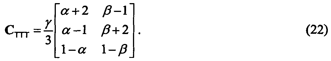
- the specific matrix Dm is to be provided as indicated by step 127.
- An example for this matrix is given in equation (24) and the definition can be derived from the corresponding equation for C nT as defined in equation (22). Equation (22), therefore, defines what is to be done in step 128.
- Step 129 defines the equations for calculat- ing matrix Cm-.
- the parameters ⁇ , ⁇ and ⁇ which are the CPC parameters, can be output.
- ⁇ is set to 1 so that the only remaining CPC parameters input into block 71 are ⁇ and ⁇ .
- the rendering matrix A is provided.
- the size of the rendering matrix A is N lines for the number of audio objects and M columns for the number of output channels.
- This rendering matrix includes the information from the scene vector, when a scene vector is used.
- the rendering matrix includes the information of placing an audio source in a certain position in an output setup.
- the rendering matrix is generated on the decoder side without any information from the encoder side. This allows a user to place the audio objects wherever the user likes without paying attention to a spatial relation of the audio objects in the encoder setup.
- the relative or absolute location of audio sources can be encoded on the encoder side and transmitted to the decoder as a kind of a scene vector. Then, on the decoder side, this information on locations of audio sources which is preferably independent of an intended audio rendering setup is processed to result in a rendering matrix which reflects the locations of the audio sources customized to the specific audio output configuration.
- the object energy matrix E which has already been discussed in connection with step 124 of Fig. 12 is provided.
- This matrix has the size of NxN and includes the audio object parameters.
- such an object energy matrix is provided for each subband and each block of time- domain samples or subband-domain samples.
- the output energy matrix F is calculated.
- F is the covariance matrix of the output channels. Since the output channels are, however, still unknown, the output energy matrix F is calculated using the rendering matrix and the energy matrix.
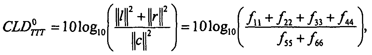
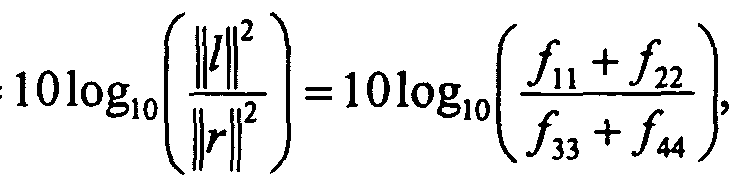
- These matrices are provided in steps 130 and 131 and are readily available on the decoder side. Then, the specific equations (15), (16), (17), (18) and (19) are applied to calculate the channel level difference parameters CLD 0 , CLDi, CLD 2 and the inter-channel coherence parameters ICCi and ICC 2 so that the parameters for the boxes 74a, 74b, 74c are available. Importantly, the spatial parameters are calculated by combining the specific elements of the output energy matrix F.
- step 133 all parameters for a spatial upmixer, such as the spatial upmixer as schematically illustrated in Fig. 7, are available.
- the object parameters were given as energy parameters.
- the object parameters are given as prediction parameters, i.e. as an object prediction matrix C as indicated by item 124a in Fig. 12
- the calculation of the reduced prediction matrix C 3 is just a matrix multiplication as illustrated in block 125a and discussed in connection with equation (32).
- the matrix A 3 as used in block 125a is the same matrix A 3 as mentioned in block 122 of Fig. 12.
- the object prediction matrix C is generated by an audio object encoder and transmitted to the decoder, then some additional calculations are required for generating the parameters for the boxes 74a, 74b, 74c. These additional steps are indicated in Fig. 13b.
- the object prediction matrix C is provided as indicated by 124a in Fig. 13b, which is the same as discussed in connection with block 124a of Fig. 12.
- the covariance matrix of the object downmix Z is calculated using the transmitted downmix or is generated and transmitted as additional side information.
- the decoder does not necessarily have to perform any energy calculations which inherently introduce some delayed processing and increase the processing load on the decoder side.
- step 134 the object energy matrix E can be calculated as indicated by step 135 by using the prediction matrix C and the downmix covariance or "downmix energy" matrix Z.
- step 135 all steps discussed in connection with Fig. 13a can be performed, such as steps 132, 133, to generate all parameters for blocks 74a, 74b, 74c of Fig. 7.
- Fig. 16 illustrates a further embodiment, in which only a stereo rendering is required.
- the stereo rendering is the output as provided by mode number 5 or line 115 of Fig. 11.
- the output data synthesizer 100 of Fig. 10 is not interested in any spatial upmix parameters but is mainly interested in a specific conversion matrix G for converting the object downmix into a useful and, of course, readily influencable and readily controllable stereo downmix.
- an M-to-2 partial downmix matrix is calculated.
- the partial downmix matrix would be a downmix matrix from six to two channels, but other downmix matrices are available as well.
- the calculation of this partial downmix matrix can be, for example, derived from the partial downmix matrix D 3 ⁇ as generated in step 121 and matrix D T ⁇ T as used in step 127 of Fig. 12.
- a stereo rendering matrix A 2 is generated using the result of step 160 and the "big" rendering matrix A is illustrated in step 161.
- the rendering matrix A is the same matrix as has been discussed in connection with block 120 in Fig. 12.
- the stereo rendering matrix may be parameterized by placement parameters ⁇ and K.
- ⁇ is set to 1 and K is set to 1 as well, then the equation (33) is obtained, which allows a variation of the voice volume in the example described in connection with equation (33).
- other parameters such as ⁇ and K are used, then the placement of the sources can be varied as well.
- the conversion matrix G is calculated by using equation (33).
- the matrix (DED * ) can be calculated, inverted and the inverted matrix can be multiplied to the right-hand side of the equation in block 163.
- the conversion matrix G is there, and the object downmix X can be converted by multiplying the conversion matrix and the object downmix as indicated in block 164.
- the converted downmix X' can be stereo-rendered using two stereo speakers.
- certain values for ⁇ , v and K can be set for calculating the conversion matrix G.
- the conversion matrix G can be calculated using all these three parameters as variables so that the parameters can be set subsequent to step 163 as required by the user.
- Preferred embodiments solve the problem of transmitting a number of individual audio objects (using a multi-channel downmix and additional control data describing the objects) and rendering the objects to a given reproduction system (loudspeaker configuration).
- a technique on how to modify the object related control data into control data that is compatible to the reproduction system is introduced. It further proposes suitable encoding methods based on the MPEG Surround coding scheme.
- the inventive methods and signals can be implemented in hardware or in software.
- the implementation can be performed using a digital storage medium, in particular a disk or a CD having electronically readable control signals stored thereon, which can cooperate with a programmable computer system such that the in- ventive methods are performed.
- the present invention is, therefore, a computer program product with a program code stored on a machine-readable carrier, the program code being configured for performing at least one of the inventive methods, when the computer program products runs on a computer.
- the inventive methods are, therefore, a computer program having a program code for performing the inventive methods, when the computer program runs on a computer.
Landscapes
- Engineering & Computer Science (AREA)
- Physics & Mathematics (AREA)
- Acoustics & Sound (AREA)
- Signal Processing (AREA)
- Multimedia (AREA)
- Human Computer Interaction (AREA)
- Audiology, Speech & Language Pathology (AREA)
- Health & Medical Sciences (AREA)
- Computational Linguistics (AREA)
- Mathematical Physics (AREA)
- Pure & Applied Mathematics (AREA)
- Mathematical Optimization (AREA)
- Mathematical Analysis (AREA)
- General Physics & Mathematics (AREA)
- Algebra (AREA)
- Theoretical Computer Science (AREA)
- Stereophonic System (AREA)
- Compression, Expansion, Code Conversion, And Decoders (AREA)
- Medicines Containing Antibodies Or Antigens For Use As Internal Diagnostic Agents (AREA)
- Investigating Or Analysing Biological Materials (AREA)
- Electron Tubes For Measurement (AREA)
- Reduction Or Emphasis Of Bandwidth Of Signals (AREA)
- Signal Processing For Digital Recording And Reproducing (AREA)
- Sorting Of Articles (AREA)
- Optical Measuring Cells (AREA)
- Telephone Function (AREA)
Abstract
Description


Claims


Priority Applications (15)
| Application Number | Priority Date | Filing Date | Title |
|---|---|---|---|
| EP07818759A EP2054875B1 (en) | 2006-10-16 | 2007-10-05 | Enhanced coding and parameter representation of multichannel downmixed object coding |
| CN2007800383647A CN101529501B (en) | 2006-10-16 | 2007-10-05 | Audio object encoder and encoding method |
| MX2009003570A MX2009003570A (en) | 2006-10-16 | 2007-10-05 | Enhanced coding and parameter representation of multichannel downmixed object coding. |
| BRPI0715559-0A BRPI0715559B1 (en) | 2006-10-16 | 2007-10-05 | IMPROVED ENCODING AND REPRESENTATION OF MULTI-CHANNEL DOWNMIX DOWNMIX OBJECT ENCODING PARAMETERS |
| KR1020107029462A KR101103987B1 (en) | 2006-10-16 | 2007-10-05 | Enhanced coding and parameter representation of multichannel downmixed object coding |
| DE602007013415T DE602007013415D1 (en) | 2006-10-16 | 2007-10-05 | ADVANCED CODING AND PARAMETER REPRESENTATION OF MULTILAYER DECREASE DECOMMODED |
| AT07818759T ATE503245T1 (en) | 2006-10-16 | 2007-10-05 | ADVANCED CODING AND PARAMETER REPRESENTATION OF MULTI-CHANNEL DOWN-MIXED OBJECT CODING |
| JP2009532703A JP5270557B2 (en) | 2006-10-16 | 2007-10-05 | Enhanced coding and parameter representation in multi-channel downmixed object coding |
| US12/445,701 US9565509B2 (en) | 2006-10-16 | 2007-10-05 | Enhanced coding and parameter representation of multichannel downmixed object coding |
| AU2007312598A AU2007312598B2 (en) | 2006-10-16 | 2007-10-05 | Enhanced coding and parameter representation of multichannel downmixed object coding |
| CA2666640A CA2666640C (en) | 2006-10-16 | 2007-10-05 | Enhanced coding and parameter representation of multichannel downmixed object coding |
| TW096137940A TWI347590B (en) | 2006-10-16 | 2007-10-11 | Audio object coder, audio object codingm ethod, audio synthesizer, audio synthesizing method, computer readable storage medium and computer program |
| NO20091901A NO340450B1 (en) | 2006-10-16 | 2009-05-14 | Improved coding and parameterization of multichannel mixed object coding |
| HK09105759.1A HK1126888A1 (en) | 2006-10-16 | 2009-06-26 | Enhanced coding and parameter representation of multichannel downmixed object coding |
| AU2011201106A AU2011201106B2 (en) | 2006-10-16 | 2011-03-11 | Enhanced coding and parameter representation of multichannel downmixed object coding |
Applications Claiming Priority (2)
| Application Number | Priority Date | Filing Date | Title |
|---|---|---|---|
| US82964906P | 2006-10-16 | 2006-10-16 | |
| US60/829,649 | 2006-10-16 |
Publications (1)
| Publication Number | Publication Date |
|---|---|
| WO2008046531A1 true WO2008046531A1 (en) | 2008-04-24 |
Family
ID=38810466
Family Applications (1)
| Application Number | Title | Priority Date | Filing Date |
|---|---|---|---|
| PCT/EP2007/008683 WO2008046531A1 (en) | 2006-10-16 | 2007-10-05 | Enhanced coding and parameter representation of multichannel downmixed object coding |
Country Status (22)
| Country | Link |
|---|---|
| US (2) | US9565509B2 (en) |
| EP (3) | EP2068307B1 (en) |
| JP (3) | JP5270557B2 (en) |
| KR (2) | KR101012259B1 (en) |
| CN (3) | CN101529501B (en) |
| AT (2) | ATE536612T1 (en) |
| AU (2) | AU2007312598B2 (en) |
| BR (1) | BRPI0715559B1 (en) |
| CA (3) | CA2666640C (en) |
| DE (1) | DE602007013415D1 (en) |
| ES (1) | ES2378734T3 (en) |
| HK (3) | HK1126888A1 (en) |
| MX (1) | MX2009003570A (en) |
| MY (1) | MY145497A (en) |
| NO (1) | NO340450B1 (en) |
| PL (1) | PL2068307T3 (en) |
| PT (1) | PT2372701E (en) |
| RU (1) | RU2430430C2 (en) |
| SG (1) | SG175632A1 (en) |
| TW (1) | TWI347590B (en) |
| UA (1) | UA94117C2 (en) |
| WO (1) | WO2008046531A1 (en) |
Cited By (38)
| Publication number | Priority date | Publication date | Assignee | Title |
|---|---|---|---|---|
| WO2008111773A1 (en) | 2007-03-09 | 2008-09-18 | Lg Electronics Inc. | A method and an apparatus for processing an audio signal |
| JP2011002574A (en) * | 2009-06-17 | 2011-01-06 | Nippon Hoso Kyokai <Nhk> | 3-dimensional sound encoding device, 3-dimensional sound decoding device, encoding program and decoding program |
| JP2011008258A (en) * | 2009-06-23 | 2011-01-13 | Korea Electronics Telecommun | High quality multi-channel audio encoding apparatus and decoding apparatus |
| JP2011048279A (en) * | 2009-08-28 | 2011-03-10 | Nippon Hoso Kyokai <Nhk> | 3-dimensional sound encoding device, 3-dimensional sound decoding device, encoding program and decoding program |
| WO2011071336A3 (en) * | 2009-12-11 | 2011-09-22 | 한국전자통신연구원 | Audio authoring apparatus and audio playback apparatus for an object-based audio service, and audio authoring method and audio playback method using same |
| WO2011055982A3 (en) * | 2009-11-04 | 2011-11-03 | 삼성전자주식회사 | Apparatus and method for encoding/decoding a multi-channel audio signal |
| CN102239520A (en) * | 2008-12-05 | 2011-11-09 | Lg电子株式会社 | A method and an apparatus for processing an audio signal |
| JP2011528200A (en) * | 2008-07-17 | 2011-11-10 | フラウンホッファー−ゲゼルシャフト ツァ フェルダールング デァ アンゲヴァンテン フォアシュンク エー.ファオ | Apparatus and method for generating an audio output signal using object-based metadata |
| JP2012500532A (en) * | 2008-08-14 | 2012-01-05 | ドルビー・ラボラトリーズ・ライセンシング・コーポレーション | Audio signal conversion |
| CN102792378A (en) * | 2010-01-06 | 2012-11-21 | Lg电子株式会社 | An apparatus for processing an audio signal and method thereof |
| US8359113B2 (en) | 2007-03-09 | 2013-01-22 | Lg Electronics Inc. | Method and an apparatus for processing an audio signal |
| US8422688B2 (en) | 2007-09-06 | 2013-04-16 | Lg Electronics Inc. | Method and an apparatus of decoding an audio signal |
| WO2013064957A1 (en) * | 2011-11-01 | 2013-05-10 | Koninklijke Philips Electronics N.V. | Audio object encoding and decoding |
| JP2013101384A (en) * | 2006-12-27 | 2013-05-23 | Electronics & Telecommunications Research Inst | Transcoding device |
| RU2495503C2 (en) * | 2008-07-29 | 2013-10-10 | Панасоник Корпорэйшн | Sound encoding device, sound decoding device, sound encoding and decoding device and teleconferencing system |
| US8670575B2 (en) | 2008-12-05 | 2014-03-11 | Lg Electronics Inc. | Method and an apparatus for processing an audio signal |
| RU2520329C2 (en) * | 2009-03-17 | 2014-06-20 | Долби Интернешнл Аб | Advanced stereo coding based on combination of adaptively selectable left/right or mid/side stereo coding and parametric stereo coding |
| WO2014111765A1 (en) * | 2013-01-15 | 2014-07-24 | Koninklijke Philips N.V. | Binaural audio processing |
| US8861739B2 (en) | 2008-11-10 | 2014-10-14 | Nokia Corporation | Apparatus and method for generating a multichannel signal |
| WO2015036352A1 (en) * | 2013-09-12 | 2015-03-19 | Dolby International Ab | Coding of multichannel audio content |
| EP2879131A1 (en) * | 2013-11-27 | 2015-06-03 | Fraunhofer-Gesellschaft zur Förderung der angewandten Forschung e.V. | Decoder, encoder and method for informed loudness estimation in object-based audio coding systems |
| US9055371B2 (en) | 2010-11-19 | 2015-06-09 | Nokia Technologies Oy | Controllable playback system offering hierarchical playback options |
| US9071919B2 (en) | 2010-10-13 | 2015-06-30 | Samsung Electronics Co., Ltd. | Apparatus and method for encoding and decoding spatial parameter |
| US9313599B2 (en) | 2010-11-19 | 2016-04-12 | Nokia Technologies Oy | Apparatus and method for multi-channel signal playback |
| US9456289B2 (en) | 2010-11-19 | 2016-09-27 | Nokia Technologies Oy | Converting multi-microphone captured signals to shifted signals useful for binaural signal processing and use thereof |
| US9564138B2 (en) | 2012-07-31 | 2017-02-07 | Intellectual Discovery Co., Ltd. | Method and device for processing audio signal |
| EP3057096A4 (en) * | 2013-10-09 | 2017-05-31 | Sony Corporation | Encoding device and method, decoding device and method, and program |
| US9706324B2 (en) | 2013-05-17 | 2017-07-11 | Nokia Technologies Oy | Spatial object oriented audio apparatus |
| US10148903B2 (en) | 2012-04-05 | 2018-12-04 | Nokia Technologies Oy | Flexible spatial audio capture apparatus |
| US10249311B2 (en) | 2013-07-22 | 2019-04-02 | Fraunhofer-Gesellschaft Zur Foerderung Der Angewandten Forschung E.V. | Concept for audio encoding and decoding for audio channels and audio objects |
| US10277998B2 (en) | 2013-07-22 | 2019-04-30 | Fraunhofer-Gesellschaft Zur Foerderung Der Angewandten Forschung E.V. | Apparatus and method for low delay object metadata coding |
| WO2019086757A1 (en) * | 2017-11-06 | 2019-05-09 | Nokia Technologies Oy | Determination of targeted spatial audio parameters and associated spatial audio playback |
| US10586545B2 (en) | 2010-04-09 | 2020-03-10 | Dolby International Ab | MDCT-based complex prediction stereo coding |
| US10635383B2 (en) | 2013-04-04 | 2020-04-28 | Nokia Technologies Oy | Visual audio processing apparatus |
| US10701504B2 (en) | 2013-07-22 | 2020-06-30 | Fraunhofer-Gesellschaft Zur Foerderung Der Angewandten Forschung E.V. | Apparatus and method for realizing a SAOC downmix of 3D audio content |
| CN112219236A (en) * | 2018-04-06 | 2021-01-12 | 诺基亚技术有限公司 | Spatial audio parameters and associated spatial audio playback |
| US10986455B2 (en) | 2013-10-23 | 2021-04-20 | Dolby Laboratories Licensing Corporation | Method for and apparatus for decoding/rendering an ambisonics audio soundfield representation for audio playback using 2D setups |
| US11412336B2 (en) | 2018-05-31 | 2022-08-09 | Nokia Technologies Oy | Signalling of spatial audio parameters |
Families Citing this family (102)
| Publication number | Priority date | Publication date | Assignee | Title |
|---|---|---|---|---|
| WO2006132857A2 (en) * | 2005-06-03 | 2006-12-14 | Dolby Laboratories Licensing Corporation | Apparatus and method for encoding audio signals with decoding instructions |
| US20090177479A1 (en) * | 2006-02-09 | 2009-07-09 | Lg Electronics Inc. | Method for Encoding and Decoding Object-Based Audio Signal and Apparatus Thereof |
| CN102768835B (en) | 2006-09-29 | 2014-11-05 | 韩国电子通信研究院 | Apparatus and method for coding and decoding multi-object audio signal with various channel |
| WO2008044901A1 (en) * | 2006-10-12 | 2008-04-17 | Lg Electronics Inc., | Apparatus for processing a mix signal and method thereof |
| CA2666640C (en) | 2006-10-16 | 2015-03-10 | Dolby Sweden Ab | Enhanced coding and parameter representation of multichannel downmixed object coding |
| RU2431940C2 (en) | 2006-10-16 | 2011-10-20 | Фраунхофер-Гезелльшафт цур Фёрдерунг дер ангевандтен Форшунг Е.Ф. | Apparatus and method for multichannel parametric conversion |
| US8571875B2 (en) | 2006-10-18 | 2013-10-29 | Samsung Electronics Co., Ltd. | Method, medium, and apparatus encoding and/or decoding multichannel audio signals |
| BRPI0711094A2 (en) * | 2006-11-24 | 2011-08-23 | Lg Eletronics Inc | method for encoding and decoding the object and apparatus based audio signal of this |
| KR101100222B1 (en) * | 2006-12-07 | 2011-12-28 | 엘지전자 주식회사 | A method an apparatus for processing an audio signal |
| US8271289B2 (en) * | 2007-02-14 | 2012-09-18 | Lg Electronics Inc. | Methods and apparatuses for encoding and decoding object-based audio signals |
| US20100241434A1 (en) * | 2007-02-20 | 2010-09-23 | Kojiro Ono | Multi-channel decoding device, multi-channel decoding method, program, and semiconductor integrated circuit |
| KR101100213B1 (en) | 2007-03-16 | 2011-12-28 | 엘지전자 주식회사 | A method and an apparatus for processing an audio signal |
| US8639498B2 (en) * | 2007-03-30 | 2014-01-28 | Electronics And Telecommunications Research Institute | Apparatus and method for coding and decoding multi object audio signal with multi channel |
| CA2701457C (en) * | 2007-10-17 | 2016-05-17 | Oliver Hellmuth | Audio coding using upmix |
| WO2009068087A1 (en) * | 2007-11-27 | 2009-06-04 | Nokia Corporation | Multichannel audio coding |
| US8543231B2 (en) * | 2007-12-09 | 2013-09-24 | Lg Electronics Inc. | Method and an apparatus for processing a signal |
| JP5248625B2 (en) | 2007-12-21 | 2013-07-31 | ディーティーエス・エルエルシー | System for adjusting the perceived loudness of audio signals |
| JP5340261B2 (en) * | 2008-03-19 | 2013-11-13 | パナソニック株式会社 | Stereo signal encoding apparatus, stereo signal decoding apparatus, and methods thereof |
| KR101461685B1 (en) * | 2008-03-31 | 2014-11-19 | 한국전자통신연구원 | Method and apparatus for generating side information bitstream of multi object audio signal |
| CN102037507B (en) * | 2008-05-23 | 2013-02-06 | 皇家飞利浦电子股份有限公司 | A parametric stereo upmix apparatus, a parametric stereo decoder, a parametric stereo downmix apparatus, a parametric stereo encoder |
| EP2395504B1 (en) * | 2009-02-13 | 2013-09-18 | Huawei Technologies Co., Ltd. | Stereo encoding method and apparatus |
| GB2470059A (en) * | 2009-05-08 | 2010-11-10 | Nokia Corp | Multi-channel audio processing using an inter-channel prediction model to form an inter-channel parameter |
| US20100324915A1 (en) * | 2009-06-23 | 2010-12-23 | Electronic And Telecommunications Research Institute | Encoding and decoding apparatuses for high quality multi-channel audio codec |
| US8538042B2 (en) | 2009-08-11 | 2013-09-17 | Dts Llc | System for increasing perceived loudness of speakers |
| MY165327A (en) | 2009-10-16 | 2018-03-21 | Fraunhofer Ges Forschung | Apparatus,method and computer program for providing one or more adjusted parameters for provision of an upmix signal representation on the basis of a downmix signal representation and a parametric side information associated with the downmix signal representation,using an average value |
| WO2011048792A1 (en) * | 2009-10-21 | 2011-04-28 | パナソニック株式会社 | Sound signal processing apparatus, sound encoding apparatus and sound decoding apparatus |
| WO2011061174A1 (en) * | 2009-11-20 | 2011-05-26 | Fraunhofer-Gesellschaft zur Förderung der angewandten Forschung e.V. | Apparatus for providing an upmix signal representation on the basis of the downmix signal representation, apparatus for providing a bitstream representing a multi-channel audio signal, methods, computer programs and bitstream representing a multi-channel audio signal using a linear combination parameter |
| US9305550B2 (en) * | 2009-12-07 | 2016-04-05 | J. Carl Cooper | Dialogue detector and correction |
| WO2011104146A1 (en) * | 2010-02-24 | 2011-09-01 | Fraunhofer-Gesellschaft zur Förderung der angewandten Forschung e.V. | Apparatus for generating an enhanced downmix signal, method for generating an enhanced downmix signal and computer program |
| US10158958B2 (en) | 2010-03-23 | 2018-12-18 | Dolby Laboratories Licensing Corporation | Techniques for localized perceptual audio |
| CN113490134B (en) | 2010-03-23 | 2023-06-09 | 杜比实验室特许公司 | Audio reproducing method and sound reproducing system |
| JP5604933B2 (en) * | 2010-03-30 | 2014-10-15 | 富士通株式会社 | Downmix apparatus and downmix method |
| EP2562750B1 (en) * | 2010-04-19 | 2020-06-10 | Panasonic Intellectual Property Corporation of America | Encoding device, decoding device, encoding method and decoding method |
| KR20120071072A (en) * | 2010-12-22 | 2012-07-02 | 한국전자통신연구원 | Broadcastiong transmitting and reproducing apparatus and method for providing the object audio |
| WO2012144127A1 (en) * | 2011-04-20 | 2012-10-26 | パナソニック株式会社 | Device and method for execution of huffman coding |
| WO2013073810A1 (en) * | 2011-11-14 | 2013-05-23 | 한국전자통신연구원 | Apparatus for encoding and apparatus for decoding supporting scalable multichannel audio signal, and method for apparatuses performing same |
| KR20130093798A (en) | 2012-01-02 | 2013-08-23 | 한국전자통신연구원 | Apparatus and method for encoding and decoding multi-channel signal |
| US9312829B2 (en) | 2012-04-12 | 2016-04-12 | Dts Llc | System for adjusting loudness of audio signals in real time |
| US9622014B2 (en) | 2012-06-19 | 2017-04-11 | Dolby Laboratories Licensing Corporation | Rendering and playback of spatial audio using channel-based audio systems |
| EP3748632A1 (en) * | 2012-07-09 | 2020-12-09 | Koninklijke Philips N.V. | Encoding and decoding of audio signals |
| US9190065B2 (en) | 2012-07-15 | 2015-11-17 | Qualcomm Incorporated | Systems, methods, apparatus, and computer-readable media for three-dimensional audio coding using basis function coefficients |
| US9761229B2 (en) | 2012-07-20 | 2017-09-12 | Qualcomm Incorporated | Systems, methods, apparatus, and computer-readable media for audio object clustering |
| US9479886B2 (en) | 2012-07-20 | 2016-10-25 | Qualcomm Incorporated | Scalable downmix design with feedback for object-based surround codec |
| RU2604337C2 (en) * | 2012-08-03 | 2016-12-10 | Фраунхофер-Гезелльшафт Цур Фердерунг Дер Ангевандтен Форшунг Е.Ф. | Decoder and method of multi-instance spatial encoding of audio objects using parametric concept for cases of the multichannel downmixing/upmixing |
| US9489954B2 (en) * | 2012-08-07 | 2016-11-08 | Dolby Laboratories Licensing Corporation | Encoding and rendering of object based audio indicative of game audio content |
| KR102033985B1 (en) | 2012-08-10 | 2019-10-18 | 프라운호퍼 게젤샤프트 쭈르 푀르데룽 데어 안겐반텐 포르슝 에. 베. | Apparatus and methods for adapting audio information in spatial audio object coding |
| KR20140027831A (en) * | 2012-08-27 | 2014-03-07 | 삼성전자주식회사 | Audio signal transmitting apparatus and method for transmitting audio signal, and audio signal receiving apparatus and method for extracting audio source thereof |
| EP2717262A1 (en) * | 2012-10-05 | 2014-04-09 | Fraunhofer-Gesellschaft zur Förderung der angewandten Forschung e.V. | Encoder, decoder and methods for signal-dependent zoom-transform in spatial audio object coding |
| JP6169718B2 (en) | 2012-12-04 | 2017-07-26 | サムスン エレクトロニクス カンパニー リミテッド | Audio providing apparatus and audio providing method |
| JP6179122B2 (en) * | 2013-02-20 | 2017-08-16 | 富士通株式会社 | Audio encoding apparatus, audio encoding method, and audio encoding program |
| JP6484605B2 (en) | 2013-03-15 | 2019-03-13 | ディーティーエス・インコーポレイテッドDTS,Inc. | Automatic multi-channel music mix from multiple audio stems |
| CN114566182A (en) | 2013-04-05 | 2022-05-31 | 杜比实验室特许公司 | Companding apparatus and method for reducing quantization noise using advanced spectral extension |
| BR112015025092B1 (en) | 2013-04-05 | 2022-01-11 | Dolby International Ab | AUDIO PROCESSING SYSTEM AND METHOD FOR PROCESSING AN AUDIO BITS FLOW |
| WO2014175591A1 (en) * | 2013-04-27 | 2014-10-30 | 인텔렉추얼디스커버리 주식회사 | Audio signal processing method |
| EP2804176A1 (en) * | 2013-05-13 | 2014-11-19 | Fraunhofer-Gesellschaft zur Förderung der angewandten Forschung e.V. | Audio object separation from mixture signal using object-specific time/frequency resolutions |
| KR101760248B1 (en) * | 2013-05-24 | 2017-07-21 | 돌비 인터네셔널 에이비 | Efficient coding of audio scenes comprising audio objects |
| RU2745832C2 (en) * | 2013-05-24 | 2021-04-01 | Долби Интернешнл Аб | Efficient encoding of audio scenes containing audio objects |
| KR102459010B1 (en) * | 2013-05-24 | 2022-10-27 | 돌비 인터네셔널 에이비 | Audio encoder and decoder |
| US10026408B2 (en) | 2013-05-24 | 2018-07-17 | Dolby International Ab | Coding of audio scenes |
| RU2628177C2 (en) * | 2013-05-24 | 2017-08-15 | Долби Интернешнл Аб | Methods of coding and decoding sound, corresponding machine-readable media and corresponding coding device and device for sound decoding |
| EP3270375B1 (en) | 2013-05-24 | 2020-01-15 | Dolby International AB | Reconstruction of audio scenes from a downmix |
| EP3005354B1 (en) * | 2013-06-05 | 2019-07-03 | Dolby International AB | Method for encoding audio signals, apparatus for encoding audio signals, method for decoding audio signals and apparatus for decoding audio signals |
| CN104240711B (en) | 2013-06-18 | 2019-10-11 | 杜比实验室特许公司 | For generating the mthods, systems and devices of adaptive audio content |
| EP3933834A1 (en) | 2013-07-05 | 2022-01-05 | Dolby International AB | Enhanced soundfield coding using parametric component generation |
| KR20150009474A (en) * | 2013-07-15 | 2015-01-26 | 한국전자통신연구원 | Encoder and encoding method for multi-channel signal, and decoder and decoding method for multi-channel signal |
| RU2665917C2 (en) | 2013-07-22 | 2018-09-04 | Фраунхофер-Гезелльшафт Цур Фердерунг Дер Ангевандтен Форшунг Е.Ф. | Multi-channel audio decoder, multi-channel audio encoder, methods, computer program and encoded audio representation using a decorrelation rendered audio signals |
| EP2830056A1 (en) | 2013-07-22 | 2015-01-28 | Fraunhofer-Gesellschaft zur Förderung der angewandten Forschung e.V. | Apparatus and method for encoding or decoding an audio signal with intelligent gap filling in the spectral domain |
| EP2830046A1 (en) | 2013-07-22 | 2015-01-28 | Fraunhofer-Gesellschaft zur Förderung der angewandten Forschung e.V. | Apparatus and method for decoding an encoded audio signal to obtain modified output signals |
| EP2830333A1 (en) | 2013-07-22 | 2015-01-28 | Fraunhofer-Gesellschaft zur Förderung der angewandten Forschung e.V. | Multi-channel decorrelator, multi-channel audio decoder, multi-channel audio encoder, methods and computer program using a premix of decorrelator input signals |
| CN110797037A (en) * | 2013-07-31 | 2020-02-14 | 杜比实验室特许公司 | Method and apparatus for processing audio data, medium, and device |
| ES2700246T3 (en) | 2013-08-28 | 2019-02-14 | Dolby Laboratories Licensing Corp | Parametric improvement of the voice |
| KR102243395B1 (en) * | 2013-09-05 | 2021-04-22 | 한국전자통신연구원 | Apparatus for encoding audio signal, apparatus for decoding audio signal, and apparatus for replaying audio signal |
| TWI774136B (en) | 2013-09-12 | 2022-08-11 | 瑞典商杜比國際公司 | Decoding method, and decoding device in multichannel audio system, computer program product comprising a non-transitory computer-readable medium with instructions for performing decoding method, audio system comprising decoding device |
| TWI557724B (en) * | 2013-09-27 | 2016-11-11 | 杜比實驗室特許公司 | A method for encoding an n-channel audio program, a method for recovery of m channels of an n-channel audio program, an audio encoder configured to encode an n-channel audio program and a decoder configured to implement recovery of an n-channel audio pro |
| EP3061089B1 (en) * | 2013-10-21 | 2018-01-17 | Dolby International AB | Parametric reconstruction of audio signals |
| EP3074970B1 (en) * | 2013-10-21 | 2018-02-21 | Dolby International AB | Audio encoder and decoder |
| EP2866227A1 (en) | 2013-10-22 | 2015-04-29 | Fraunhofer-Gesellschaft zur Förderung der angewandten Forschung e.V. | Method for decoding and encoding a downmix matrix, method for presenting audio content, encoder and decoder for a downmix matrix, audio encoder and audio decoder |
| KR102107554B1 (en) * | 2013-11-18 | 2020-05-07 | 인포뱅크 주식회사 | A Method for synthesizing multimedia using network |
| WO2015105748A1 (en) | 2014-01-09 | 2015-07-16 | Dolby Laboratories Licensing Corporation | Spatial error metrics of audio content |
| KR101904423B1 (en) * | 2014-09-03 | 2018-11-28 | 삼성전자주식회사 | Method and apparatus for learning and recognizing audio signal |
| US9774974B2 (en) * | 2014-09-24 | 2017-09-26 | Electronics And Telecommunications Research Institute | Audio metadata providing apparatus and method, and multichannel audio data playback apparatus and method to support dynamic format conversion |
| TWI587286B (en) | 2014-10-31 | 2017-06-11 | 杜比國際公司 | Method and system for decoding and encoding of audio signals, computer program product, and computer-readable medium |
| EP3067885A1 (en) * | 2015-03-09 | 2016-09-14 | Fraunhofer-Gesellschaft zur Förderung der angewandten Forschung e.V. | Apparatus and method for encoding or decoding a multi-channel signal |
| CN113055802B (en) * | 2015-07-16 | 2022-11-08 | 索尼公司 | Information processing apparatus, information processing method, and computer readable medium |
| CA3219512A1 (en) | 2015-08-25 | 2017-03-02 | Dolby International Ab | Audio encoding and decoding using presentation transform parameters |
| RU2728535C2 (en) * | 2015-09-25 | 2020-07-30 | Войсэйдж Корпорейшн | Method and system using difference of long-term correlations between left and right channels for downmixing in time area of stereophonic audio signal to primary and secondary channels |
| US9961467B2 (en) * | 2015-10-08 | 2018-05-01 | Qualcomm Incorporated | Conversion from channel-based audio to HOA |
| CN108476366B (en) | 2015-11-17 | 2021-03-26 | 杜比实验室特许公司 | Head tracking for parametric binaural output systems and methods |
| RU2722391C2 (en) * | 2015-11-17 | 2020-05-29 | Долби Лэборетериз Лайсенсинг Корпорейшн | System and method of tracking movement of head for obtaining parametric binaural output signal |
| KR102640940B1 (en) | 2016-01-27 | 2024-02-26 | 돌비 레버러토리즈 라이쎈싱 코오포레이션 | Acoustic environment simulation |
| US10158758B2 (en) | 2016-11-02 | 2018-12-18 | International Business Machines Corporation | System and method for monitoring and visualizing emotions in call center dialogs at call centers |
| US10135979B2 (en) * | 2016-11-02 | 2018-11-20 | International Business Machines Corporation | System and method for monitoring and visualizing emotions in call center dialogs by call center supervisors |
| CN106604199B (en) * | 2016-12-23 | 2018-09-18 | 湖南国科微电子股份有限公司 | A kind of matrix disposal method and device of digital audio and video signals |
| US10650834B2 (en) | 2018-01-10 | 2020-05-12 | Savitech Corp. | Audio processing method and non-transitory computer readable medium |
| CN110556119B (en) * | 2018-05-31 | 2022-02-18 | 华为技术有限公司 | Method and device for calculating downmix signal |
| CN110970008A (en) * | 2018-09-28 | 2020-04-07 | 广州灵派科技有限公司 | Embedded sound mixing method and device, embedded equipment and storage medium |
| BR112021007089A2 (en) | 2018-11-13 | 2021-07-20 | Dolby Laboratories Licensing Corporation | audio processing in immersive audio services |
| KR20220024593A (en) | 2019-06-14 | 2022-03-03 | 프라운호퍼 게젤샤프트 쭈르 푀르데룽 데어 안겐반텐 포르슝 에. 베. | Parameter encoding and decoding |
| KR102079691B1 (en) * | 2019-11-11 | 2020-02-19 | 인포뱅크 주식회사 | A terminal for synthesizing multimedia using network |
| WO2022245076A1 (en) * | 2021-05-21 | 2022-11-24 | 삼성전자 주식회사 | Apparatus and method for processing multi-channel audio signal |
| CN114463584B (en) * | 2022-01-29 | 2023-03-24 | 北京百度网讯科技有限公司 | Image processing method, model training method, device, apparatus, storage medium, and program |
| CN114501297B (en) * | 2022-04-02 | 2022-09-02 | 北京荣耀终端有限公司 | Audio processing method and electronic equipment |
Citations (2)
| Publication number | Priority date | Publication date | Assignee | Title |
|---|---|---|---|---|
| WO1999052326A1 (en) * | 1998-04-07 | 1999-10-14 | Ray Milton Dolby | Low bit-rate spatial coding method and system |
| WO2006048203A1 (en) * | 2004-11-02 | 2006-05-11 | Coding Technologies Ab | Methods for improved performance of prediction based multi-channel reconstruction |
Family Cites Families (60)
| Publication number | Priority date | Publication date | Assignee | Title |
|---|---|---|---|---|
| SG43996A1 (en) * | 1993-06-22 | 1997-11-14 | Thomson Brandt Gmbh | Method for obtaining a multi-channel decoder matrix |
| CA2157024C (en) * | 1994-02-17 | 1999-08-10 | Kenneth A. Stewart | Method and apparatus for group encoding signals |
| US6128597A (en) * | 1996-05-03 | 2000-10-03 | Lsi Logic Corporation | Audio decoder with a reconfigurable downmixing/windowing pipeline and method therefor |
| US5912976A (en) * | 1996-11-07 | 1999-06-15 | Srs Labs, Inc. | Multi-channel audio enhancement system for use in recording and playback and methods for providing same |
| JP3743671B2 (en) * | 1997-11-28 | 2006-02-08 | 日本ビクター株式会社 | Audio disc and audio playback device |
| JP2005093058A (en) * | 1997-11-28 | 2005-04-07 | Victor Co Of Japan Ltd | Method for encoding and decoding audio signal |
| US6788880B1 (en) | 1998-04-16 | 2004-09-07 | Victor Company Of Japan, Ltd | Recording medium having a first area for storing an audio title set and a second area for storing a still picture set and apparatus for processing the recorded information |
| US6122619A (en) * | 1998-06-17 | 2000-09-19 | Lsi Logic Corporation | Audio decoder with programmable downmixing of MPEG/AC-3 and method therefor |
| KR100915120B1 (en) | 1999-04-07 | 2009-09-03 | 돌비 레버러토리즈 라이쎈싱 코오포레이션 | Apparatus and method for lossless encoding and decoding multi-channel audio signals |
| KR100392384B1 (en) | 2001-01-13 | 2003-07-22 | 한국전자통신연구원 | Apparatus and Method for delivery of MPEG-4 data synchronized to MPEG-2 data |
| US7292901B2 (en) | 2002-06-24 | 2007-11-06 | Agere Systems Inc. | Hybrid multi-channel/cue coding/decoding of audio signals |
| JP2002369152A (en) | 2001-06-06 | 2002-12-20 | Canon Inc | Image processor, image processing method, image processing program, and storage media readable by computer where image processing program is stored |
| DE60225819T2 (en) * | 2001-09-14 | 2009-04-09 | Aleris Aluminum Koblenz Gmbh | PROCESS FOR COATING REMOVAL OF SCRAP PARTS WITH METALLIC COATING |
| US20050141722A1 (en) * | 2002-04-05 | 2005-06-30 | Koninklijke Philips Electronics N.V. | Signal processing |
| JP3994788B2 (en) * | 2002-04-30 | 2007-10-24 | ソニー株式会社 | Transfer characteristic measuring apparatus, transfer characteristic measuring method, transfer characteristic measuring program, and amplifying apparatus |
| RU2363116C2 (en) | 2002-07-12 | 2009-07-27 | Конинклейке Филипс Электроникс Н.В. | Audio encoding |
| EP1523863A1 (en) | 2002-07-16 | 2005-04-20 | Koninklijke Philips Electronics N.V. | Audio coding |
| JP2004193877A (en) | 2002-12-10 | 2004-07-08 | Sony Corp | Sound image localization signal processing apparatus and sound image localization signal processing method |
| KR20040060718A (en) * | 2002-12-28 | 2004-07-06 | 삼성전자주식회사 | Method and apparatus for mixing audio stream and information storage medium thereof |
| KR20050116828A (en) | 2003-03-24 | 2005-12-13 | 코닌클리케 필립스 일렉트로닉스 엔.브이. | Coding of main and side signal representing a multichannel signal |
| US7447317B2 (en) * | 2003-10-02 | 2008-11-04 | Fraunhofer-Gesellschaft Zur Foerderung Der Angewandten Forschung E.V | Compatible multi-channel coding/decoding by weighting the downmix channel |
| JP4378157B2 (en) | 2003-11-14 | 2009-12-02 | キヤノン株式会社 | Data processing method and apparatus |
| US7555009B2 (en) * | 2003-11-14 | 2009-06-30 | Canon Kabushiki Kaisha | Data processing method and apparatus, and data distribution method and information processing apparatus |
| US7805313B2 (en) * | 2004-03-04 | 2010-09-28 | Agere Systems Inc. | Frequency-based coding of channels in parametric multi-channel coding systems |
| RU2396608C2 (en) | 2004-04-05 | 2010-08-10 | Конинклейке Филипс Электроникс Н.В. | Method, device, coding device, decoding device and audio system |
| EP1895512A3 (en) * | 2004-04-05 | 2014-09-17 | Koninklijke Philips N.V. | Multi-channel encoder |
| SE0400998D0 (en) * | 2004-04-16 | 2004-04-16 | Cooding Technologies Sweden Ab | Method for representing multi-channel audio signals |
| US7391870B2 (en) * | 2004-07-09 | 2008-06-24 | Fraunhofer-Gesellschaft Zur Foerderung Der Angewandten Forschung E V | Apparatus and method for generating a multi-channel output signal |
| TWI393121B (en) | 2004-08-25 | 2013-04-11 | Dolby Lab Licensing Corp | Method and apparatus for processing a set of n audio signals, and computer program associated therewith |
| RU2007107348A (en) * | 2004-08-31 | 2008-09-10 | Мацусита Электрик Индастриал Ко., Лтд. (Jp) | DEVICE AND METHOD FOR GENERATING A STEREO SIGNAL |
| JP2006101248A (en) | 2004-09-30 | 2006-04-13 | Victor Co Of Japan Ltd | Sound field compensation device |
| US8340306B2 (en) * | 2004-11-30 | 2012-12-25 | Agere Systems Llc | Parametric coding of spatial audio with object-based side information |
| EP1691348A1 (en) | 2005-02-14 | 2006-08-16 | Ecole Polytechnique Federale De Lausanne | Parametric joint-coding of audio sources |
| US7573912B2 (en) * | 2005-02-22 | 2009-08-11 | Fraunhofer-Gesellschaft Zur Foerderung Der Angewandten Forschunng E.V. | Near-transparent or transparent multi-channel encoder/decoder scheme |
| WO2006103584A1 (en) * | 2005-03-30 | 2006-10-05 | Koninklijke Philips Electronics N.V. | Multi-channel audio coding |
| US7991610B2 (en) * | 2005-04-13 | 2011-08-02 | Fraunhofer-Gesellschaft Zur Foerderung Der Angewandten Forschung E.V. | Adaptive grouping of parameters for enhanced coding efficiency |
| US7961890B2 (en) * | 2005-04-15 | 2011-06-14 | Fraunhofer-Gesellschaft Zur Foerderung Der Angewandten Forschung, E.V. | Multi-channel hierarchical audio coding with compact side information |
| US8185403B2 (en) * | 2005-06-30 | 2012-05-22 | Lg Electronics Inc. | Method and apparatus for encoding and decoding an audio signal |
| US20070055510A1 (en) * | 2005-07-19 | 2007-03-08 | Johannes Hilpert | Concept for bridging the gap between parametric multi-channel audio coding and matrixed-surround multi-channel coding |
| JP5113049B2 (en) * | 2005-07-29 | 2013-01-09 | エルジー エレクトロニクス インコーポレイティド | Method for generating encoded audio signal and method for processing audio signal |
| WO2007055463A1 (en) * | 2005-08-30 | 2007-05-18 | Lg Electronics Inc. | Apparatus for encoding and decoding audio signal and method thereof |
| KR100857105B1 (en) * | 2005-09-14 | 2008-09-05 | 엘지전자 주식회사 | Method and apparatus for decoding an audio signal |
| JP2009514008A (en) * | 2005-10-26 | 2009-04-02 | エルジー エレクトロニクス インコーポレイティド | Multi-channel audio signal encoding and decoding method and apparatus |
| KR100888474B1 (en) * | 2005-11-21 | 2009-03-12 | 삼성전자주식회사 | Apparatus and method for encoding/decoding multichannel audio signal |
| KR100644715B1 (en) * | 2005-12-19 | 2006-11-10 | 삼성전자주식회사 | Method and apparatus for active audio matrix decoding |
| KR100885700B1 (en) | 2006-01-19 | 2009-02-26 | 엘지전자 주식회사 | Method and apparatus for decoding a signal |
| US9426596B2 (en) * | 2006-02-03 | 2016-08-23 | Electronics And Telecommunications Research Institute | Method and apparatus for control of randering multiobject or multichannel audio signal using spatial cue |
| WO2007089129A1 (en) * | 2006-02-03 | 2007-08-09 | Electronics And Telecommunications Research Institute | Apparatus and method for visualization of multichannel audio signals |
| US20090177479A1 (en) * | 2006-02-09 | 2009-07-09 | Lg Electronics Inc. | Method for Encoding and Decoding Object-Based Audio Signal and Apparatus Thereof |
| JP2009526467A (en) | 2006-02-09 | 2009-07-16 | エルジー エレクトロニクス インコーポレイティド | Method and apparatus for encoding and decoding object-based audio signal |
| ATE532350T1 (en) * | 2006-03-24 | 2011-11-15 | Dolby Sweden Ab | GENERATION OF SPATIAL DOWNMIXINGS FROM PARAMETRIC REPRESENTATIONS OF MULTI-CHANNEL SIGNALS |
| JP4875142B2 (en) * | 2006-03-28 | 2012-02-15 | テレフオンアクチーボラゲット エル エム エリクソン(パブル) | Method and apparatus for a decoder for multi-channel surround sound |
| US7965848B2 (en) * | 2006-03-29 | 2011-06-21 | Dolby International Ab | Reduced number of channels decoding |
| ATE527833T1 (en) | 2006-05-04 | 2011-10-15 | Lg Electronics Inc | IMPROVE STEREO AUDIO SIGNALS WITH REMIXING |
| CA2656867C (en) * | 2006-07-07 | 2013-01-08 | Johannes Hilpert | Apparatus and method for combining multiple parametrically coded audio sources |
| US20080235006A1 (en) * | 2006-08-18 | 2008-09-25 | Lg Electronics, Inc. | Method and Apparatus for Decoding an Audio Signal |
| AU2007300813B2 (en) * | 2006-09-29 | 2010-10-14 | Lg Electronics Inc. | Methods and apparatuses for encoding and decoding object-based audio signals |
| CN102768835B (en) | 2006-09-29 | 2014-11-05 | 韩国电子通信研究院 | Apparatus and method for coding and decoding multi-object audio signal with various channel |
| WO2008044901A1 (en) * | 2006-10-12 | 2008-04-17 | Lg Electronics Inc., | Apparatus for processing a mix signal and method thereof |
| CA2666640C (en) | 2006-10-16 | 2015-03-10 | Dolby Sweden Ab | Enhanced coding and parameter representation of multichannel downmixed object coding |
-
2007
- 2007-10-05 CA CA2666640A patent/CA2666640C/en active Active
- 2007-10-05 AT AT09004406T patent/ATE536612T1/en active
- 2007-10-05 EP EP09004406A patent/EP2068307B1/en active Active
- 2007-10-05 PL PL09004406T patent/PL2068307T3/en unknown
- 2007-10-05 WO PCT/EP2007/008683 patent/WO2008046531A1/en active Application Filing
- 2007-10-05 ES ES09004406T patent/ES2378734T3/en active Active
- 2007-10-05 KR KR1020097007957A patent/KR101012259B1/en active IP Right Grant
- 2007-10-05 CN CN2007800383647A patent/CN101529501B/en active Active
- 2007-10-05 UA UAA200903977A patent/UA94117C2/en unknown
- 2007-10-05 MY MYPI20091442A patent/MY145497A/en unknown
- 2007-10-05 DE DE602007013415T patent/DE602007013415D1/en active Active
- 2007-10-05 CA CA2874454A patent/CA2874454C/en active Active
- 2007-10-05 CN CN201310285571.XA patent/CN103400583B/en active Active
- 2007-10-05 CA CA2874451A patent/CA2874451C/en active Active
- 2007-10-05 PT PT111539383T patent/PT2372701E/en unknown
- 2007-10-05 US US12/445,701 patent/US9565509B2/en active Active
- 2007-10-05 BR BRPI0715559-0A patent/BRPI0715559B1/en active IP Right Grant
- 2007-10-05 JP JP2009532703A patent/JP5270557B2/en active Active
- 2007-10-05 CN CN201210276103.1A patent/CN102892070B/en active Active
- 2007-10-05 EP EP11153938.3A patent/EP2372701B1/en active Active
- 2007-10-05 RU RU2009113055/09A patent/RU2430430C2/en active
- 2007-10-05 EP EP07818759A patent/EP2054875B1/en active Active
- 2007-10-05 KR KR1020107029462A patent/KR101103987B1/en active IP Right Grant
- 2007-10-05 MX MX2009003570A patent/MX2009003570A/en active IP Right Grant
- 2007-10-05 SG SG2011075256A patent/SG175632A1/en unknown
- 2007-10-05 AT AT07818759T patent/ATE503245T1/en not_active IP Right Cessation
- 2007-10-05 AU AU2007312598A patent/AU2007312598B2/en active Active
- 2007-10-11 TW TW096137940A patent/TWI347590B/en active
-
2009
- 2009-05-14 NO NO20091901A patent/NO340450B1/en unknown
- 2009-06-26 HK HK09105759.1A patent/HK1126888A1/en unknown
- 2009-06-26 HK HK12103182.8A patent/HK1162736A1/en unknown
- 2009-06-26 HK HK09111503.8A patent/HK1133116A1/en unknown
-
2011
- 2011-03-11 AU AU2011201106A patent/AU2011201106B2/en active Active
-
2012
- 2012-03-22 JP JP2012064886A patent/JP5297544B2/en active Active
-
2013
- 2013-05-13 JP JP2013100865A patent/JP5592974B2/en active Active
-
2016
- 2016-11-04 US US15/344,170 patent/US20170084285A1/en not_active Abandoned
Patent Citations (2)
| Publication number | Priority date | Publication date | Assignee | Title |
|---|---|---|---|---|
| WO1999052326A1 (en) * | 1998-04-07 | 1999-10-14 | Ray Milton Dolby | Low bit-rate spatial coding method and system |
| WO2006048203A1 (en) * | 2004-11-02 | 2006-05-11 | Coding Technologies Ab | Methods for improved performance of prediction based multi-channel reconstruction |
Non-Patent Citations (5)
| Title |
|---|
| "Concepts of Object-Oriented Spatial Audio Coding", VIDEO STANDARDS AND DRAFTS, 21 July 2006 (2006-07-21), XP030014821 * |
| "ISO/IEC 23003-1:2006/FDIS, MPEG Surround", GENEVA : ISO, CH, 21 July 2006 (2006-07-21), XP030014816 * |
| BREEBAART J ET AL: "MPEG spatial audio coding / MPEG surround: Overview and current status", 7 October 2005, AUDIO ENGINEERING SOCIETY CONVENTION PAPER, NEW YORK, NY, US, PAGE(S) 1-15, XP002364486 * |
| BREEBAART J ET AL: "Multi-channel goes mobile: MPEG surround binaural rendering", AES INTERNATIONAL CONFERENCE. AUDIO FOR MOBILE AND HANDHELD DEVICES, XX, XX, 2 September 2006 (2006-09-02), pages 1 - 13, XP007902577 * |
| HERRE J ET AL: "THE REFERENCE MODEL ARCHITECTURE FOR MPEG SPATIAL AUDIO CODING", AUDIO ENGINEERING SOCIETY CONVENTION PAPER, NEW YORK, NY, US, 28 May 2005 (2005-05-28), pages 1 - 13, XP009059973 * |
Cited By (113)
| Publication number | Priority date | Publication date | Assignee | Title |
|---|---|---|---|---|
| US9257127B2 (en) | 2006-12-27 | 2016-02-09 | Electronics And Telecommunications Research Institute | Apparatus and method for coding and decoding multi-object audio signal with various channel including information bitstream conversion |
| JP2013101384A (en) * | 2006-12-27 | 2013-05-23 | Electronics & Telecommunications Research Inst | Transcoding device |
| US8594817B2 (en) | 2007-03-09 | 2013-11-26 | Lg Electronics Inc. | Method and an apparatus for processing an audio signal |
| EP2137726A1 (en) * | 2007-03-09 | 2009-12-30 | LG Electronics Inc. | A method and an apparatus for processing an audio signal |
| EP2137726A4 (en) * | 2007-03-09 | 2010-06-16 | Lg Electronics Inc | A method and an apparatus for processing an audio signal |
| WO2008111773A1 (en) | 2007-03-09 | 2008-09-18 | Lg Electronics Inc. | A method and an apparatus for processing an audio signal |
| US8463413B2 (en) | 2007-03-09 | 2013-06-11 | Lg Electronics Inc. | Method and an apparatus for processing an audio signal |
| US8359113B2 (en) | 2007-03-09 | 2013-01-22 | Lg Electronics Inc. | Method and an apparatus for processing an audio signal |
| US8532306B2 (en) | 2007-09-06 | 2013-09-10 | Lg Electronics Inc. | Method and an apparatus of decoding an audio signal |
| US8422688B2 (en) | 2007-09-06 | 2013-04-16 | Lg Electronics Inc. | Method and an apparatus of decoding an audio signal |
| JP2011528200A (en) * | 2008-07-17 | 2011-11-10 | フラウンホッファー−ゲゼルシャフト ツァ フェルダールング デァ アンゲヴァンテン フォアシュンク エー.ファオ | Apparatus and method for generating an audio output signal using object-based metadata |
| RU2495503C2 (en) * | 2008-07-29 | 2013-10-10 | Панасоник Корпорэйшн | Sound encoding device, sound decoding device, sound encoding and decoding device and teleconferencing system |
| KR101335975B1 (en) | 2008-08-14 | 2013-12-04 | 돌비 레버러토리즈 라이쎈싱 코오포레이션 | A method for reformatting a plurality of audio input signals |
| JP2012500532A (en) * | 2008-08-14 | 2012-01-05 | ドルビー・ラボラトリーズ・ライセンシング・コーポレーション | Audio signal conversion |
| US8861739B2 (en) | 2008-11-10 | 2014-10-14 | Nokia Corporation | Apparatus and method for generating a multichannel signal |
| US9502043B2 (en) | 2008-12-05 | 2016-11-22 | Lg Electronics Inc. | Method and an apparatus for processing an audio signal |
| CN102239520A (en) * | 2008-12-05 | 2011-11-09 | Lg电子株式会社 | A method and an apparatus for processing an audio signal |
| US8670575B2 (en) | 2008-12-05 | 2014-03-11 | Lg Electronics Inc. | Method and an apparatus for processing an audio signal |
| US9082395B2 (en) | 2009-03-17 | 2015-07-14 | Dolby International Ab | Advanced stereo coding based on a combination of adaptively selectable left/right or mid/side stereo coding and of parametric stereo coding |
| US11133013B2 (en) | 2009-03-17 | 2021-09-28 | Dolby International Ab | Audio encoder with selectable L/R or M/S coding |
| US10297259B2 (en) | 2009-03-17 | 2019-05-21 | Dolby International Ab | Advanced stereo coding based on a combination of adaptively selectable left/right or mid/side stereo coding and of parametric stereo coding |
| RU2730469C2 (en) * | 2009-03-17 | 2020-08-24 | Долби Интернешнл Аб | Improved stereo coding based on a combination of adaptively selected left/right or middle/side stereophonic coding and parametric stereophonic coding |
| US9905230B2 (en) | 2009-03-17 | 2018-02-27 | Dolby International Ab | Advanced stereo coding based on a combination of adaptively selectable left/right or mid/side stereo coding and of parametric stereo coding |
| US11322161B2 (en) | 2009-03-17 | 2022-05-03 | Dolby International Ab | Audio encoder with selectable L/R or M/S coding |
| RU2614573C2 (en) * | 2009-03-17 | 2017-03-28 | Долби Интернешнл Аб | Advanced stereo coding based on combination of adaptively selectable left/right or mid/side stereo coding and of parametric stereo coding |
| RU2520329C2 (en) * | 2009-03-17 | 2014-06-20 | Долби Интернешнл Аб | Advanced stereo coding based on combination of adaptively selectable left/right or mid/side stereo coding and parametric stereo coding |
| US11315576B2 (en) | 2009-03-17 | 2022-04-26 | Dolby International Ab | Selectable linear predictive or transform coding modes with advanced stereo coding |
| US11017785B2 (en) | 2009-03-17 | 2021-05-25 | Dolby International Ab | Advanced stereo coding based on a combination of adaptively selectable left/right or mid/side stereo coding and of parametric stereo coding |
| US10796703B2 (en) | 2009-03-17 | 2020-10-06 | Dolby International Ab | Audio encoder with selectable L/R or M/S coding |
| JP2011002574A (en) * | 2009-06-17 | 2011-01-06 | Nippon Hoso Kyokai <Nhk> | 3-dimensional sound encoding device, 3-dimensional sound decoding device, encoding program and decoding program |
| JP2011008258A (en) * | 2009-06-23 | 2011-01-13 | Korea Electronics Telecommun | High quality multi-channel audio encoding apparatus and decoding apparatus |
| JP2013174891A (en) * | 2009-06-23 | 2013-09-05 | Korea Electronics Telecommun | High quality multi-channel audio encoding and decoding apparatus |
| JP2011048279A (en) * | 2009-08-28 | 2011-03-10 | Nippon Hoso Kyokai <Nhk> | 3-dimensional sound encoding device, 3-dimensional sound decoding device, encoding program and decoding program |
| WO2011055982A3 (en) * | 2009-11-04 | 2011-11-03 | 삼성전자주식회사 | Apparatus and method for encoding/decoding a multi-channel audio signal |
| WO2011071336A3 (en) * | 2009-12-11 | 2011-09-22 | 한국전자통신연구원 | Audio authoring apparatus and audio playback apparatus for an object-based audio service, and audio authoring method and audio playback method using same |
| EP2511908A2 (en) * | 2009-12-11 | 2012-10-17 | Electronics and Telecommunications Research Institute | Audio authoring apparatus and audio playback apparatus for an object-based audio service, and audio authoring method and audio playback method using same |
| KR101464797B1 (en) * | 2009-12-11 | 2014-11-26 | 한국전자통신연구원 | Apparatus and method for making and playing audio for object based audio service |
| EP2511908A4 (en) * | 2009-12-11 | 2013-07-31 | Korea Electronics Telecomm | Audio authoring apparatus and audio playback apparatus for an object-based audio service, and audio authoring method and audio playback method using same |
| US9502042B2 (en) | 2010-01-06 | 2016-11-22 | Lg Electronics Inc. | Apparatus for processing an audio signal and method thereof |
| CN102792378A (en) * | 2010-01-06 | 2012-11-21 | Lg电子株式会社 | An apparatus for processing an audio signal and method thereof |
| US9536529B2 (en) | 2010-01-06 | 2017-01-03 | Lg Electronics Inc. | Apparatus for processing an audio signal and method thereof |
| US9042559B2 (en) | 2010-01-06 | 2015-05-26 | Lg Electronics Inc. | Apparatus for processing an audio signal and method thereof |
| US10586545B2 (en) | 2010-04-09 | 2020-03-10 | Dolby International Ab | MDCT-based complex prediction stereo coding |
| US10734002B2 (en) | 2010-04-09 | 2020-08-04 | Dolby International Ab | Audio upmixer operable in prediction or non-prediction mode |
| US11264038B2 (en) | 2010-04-09 | 2022-03-01 | Dolby International Ab | MDCT-based complex prediction stereo coding |
| US11217259B2 (en) | 2010-04-09 | 2022-01-04 | Dolby International Ab | Audio upmixer operable in prediction or non-prediction mode |
| US11810582B2 (en) | 2010-04-09 | 2023-11-07 | Dolby International Ab | MDCT-based complex prediction stereo coding |
| RU2717387C1 (en) * | 2010-04-09 | 2020-03-23 | Долби Интернешнл Аб | Audio upmix device configured to operate in prediction mode or in mode without prediction |
| US9071919B2 (en) | 2010-10-13 | 2015-06-30 | Samsung Electronics Co., Ltd. | Apparatus and method for encoding and decoding spatial parameter |
| US9456289B2 (en) | 2010-11-19 | 2016-09-27 | Nokia Technologies Oy | Converting multi-microphone captured signals to shifted signals useful for binaural signal processing and use thereof |
| US9313599B2 (en) | 2010-11-19 | 2016-04-12 | Nokia Technologies Oy | Apparatus and method for multi-channel signal playback |
| US9794686B2 (en) | 2010-11-19 | 2017-10-17 | Nokia Technologies Oy | Controllable playback system offering hierarchical playback options |
| US9055371B2 (en) | 2010-11-19 | 2015-06-09 | Nokia Technologies Oy | Controllable playback system offering hierarchical playback options |
| US10477335B2 (en) | 2010-11-19 | 2019-11-12 | Nokia Technologies Oy | Converting multi-microphone captured signals to shifted signals useful for binaural signal processing and use thereof |
| WO2013064957A1 (en) * | 2011-11-01 | 2013-05-10 | Koninklijke Philips Electronics N.V. | Audio object encoding and decoding |
| RU2618383C2 (en) * | 2011-11-01 | 2017-05-03 | Конинклейке Филипс Н.В. | Encoding and decoding of audio objects |
| US9966080B2 (en) | 2011-11-01 | 2018-05-08 | Koninklijke Philips N.V. | Audio object encoding and decoding |
| US10419712B2 (en) | 2012-04-05 | 2019-09-17 | Nokia Technologies Oy | Flexible spatial audio capture apparatus |
| US10148903B2 (en) | 2012-04-05 | 2018-12-04 | Nokia Technologies Oy | Flexible spatial audio capture apparatus |
| US9646620B1 (en) | 2012-07-31 | 2017-05-09 | Intellectual Discovery Co., Ltd. | Method and device for processing audio signal |
| US9564138B2 (en) | 2012-07-31 | 2017-02-07 | Intellectual Discovery Co., Ltd. | Method and device for processing audio signal |
| US10506358B2 (en) | 2013-01-15 | 2019-12-10 | Koninklijke Philips N.V. | Binaural audio processing |
| US9860663B2 (en) | 2013-01-15 | 2018-01-02 | Koninklijke Philips N.V. | Binaural audio processing |
| WO2014111765A1 (en) * | 2013-01-15 | 2014-07-24 | Koninklijke Philips N.V. | Binaural audio processing |
| RU2660611C2 (en) * | 2013-01-15 | 2018-07-06 | Конинклейке Филипс Н.В. | Binaural stereo processing |
| CN104904239A (en) * | 2013-01-15 | 2015-09-09 | 皇家飞利浦有限公司 | Binaural audio processing |
| US10334379B2 (en) | 2013-01-15 | 2019-06-25 | Koninklijke Philips N.V. | Binaural audio processing |
| US10334380B2 (en) | 2013-01-15 | 2019-06-25 | Koninklijke Philips N.V. | Binaural audio processing |
| US10635383B2 (en) | 2013-04-04 | 2020-04-28 | Nokia Technologies Oy | Visual audio processing apparatus |
| US9706324B2 (en) | 2013-05-17 | 2017-07-11 | Nokia Technologies Oy | Spatial object oriented audio apparatus |
| US11984131B2 (en) | 2013-07-22 | 2024-05-14 | Fraunhofer-Gesellschaft Zur Foerderung Der Angewandten Forschung E.V. | Concept for audio encoding and decoding for audio channels and audio objects |
| US11330386B2 (en) | 2013-07-22 | 2022-05-10 | Fraunhofer-Gesellschaft Zur Foerderung Der Angewandten Forschung E.V. | Apparatus and method for realizing a SAOC downmix of 3D audio content |
| US11463831B2 (en) | 2013-07-22 | 2022-10-04 | Fraunhofer-Gesellschaft Zur Foerderung Der Angewandten Forschung E.V. | Apparatus and method for efficient object metadata coding |
| US11910176B2 (en) | 2013-07-22 | 2024-02-20 | Fraunhofer-Gesellschaft Zur Foerderung Der Angewandten Forschung E.V. | Apparatus and method for low delay object metadata coding |
| US10249311B2 (en) | 2013-07-22 | 2019-04-02 | Fraunhofer-Gesellschaft Zur Foerderung Der Angewandten Forschung E.V. | Concept for audio encoding and decoding for audio channels and audio objects |
| US11227616B2 (en) | 2013-07-22 | 2022-01-18 | Fraunhofer-Gesellschaft Zur Foerderung Der Angewandten Forschung E.V. | Concept for audio encoding and decoding for audio channels and audio objects |
| US10277998B2 (en) | 2013-07-22 | 2019-04-30 | Fraunhofer-Gesellschaft Zur Foerderung Der Angewandten Forschung E.V. | Apparatus and method for low delay object metadata coding |
| US10659900B2 (en) | 2013-07-22 | 2020-05-19 | Fraunhofer-Gesellschaft Zur Foerderung Der Angewandten Forschung E.V. | Apparatus and method for low delay object metadata coding |
| US10701504B2 (en) | 2013-07-22 | 2020-06-30 | Fraunhofer-Gesellschaft Zur Foerderung Der Angewandten Forschung E.V. | Apparatus and method for realizing a SAOC downmix of 3D audio content |
| US11337019B2 (en) | 2013-07-22 | 2022-05-17 | Fraunhofer-Gesellschaft Zur Foerderung Der Angewandten Forschung E.V. | Apparatus and method for low delay object metadata coding |
| US10715943B2 (en) | 2013-07-22 | 2020-07-14 | Fraunhofer-Gesellschaft Zur Foerderung Der Angewandten Forschung E.V. | Apparatus and method for efficient object metadata coding |
| US9899029B2 (en) | 2013-09-12 | 2018-02-20 | Dolby International Ab | Coding of multichannel audio content |
| US10593340B2 (en) | 2013-09-12 | 2020-03-17 | Dolby International Ab | Methods and apparatus for decoding encoded audio signal(s) |
| WO2015036352A1 (en) * | 2013-09-12 | 2015-03-19 | Dolby International Ab | Coding of multichannel audio content |
| US11776552B2 (en) | 2013-09-12 | 2023-10-03 | Dolby International Ab | Methods and apparatus for decoding encoded audio signal(s) |
| US11410665B2 (en) | 2013-09-12 | 2022-08-09 | Dolby International Ab | Methods and apparatus for decoding encoded audio signal(s) |
| US9646619B2 (en) | 2013-09-12 | 2017-05-09 | Dolby International Ab | Coding of multichannel audio content |
| US10325607B2 (en) | 2013-09-12 | 2019-06-18 | Dolby International Ab | Coding of multichannel audio content |
| US9781539B2 (en) | 2013-10-09 | 2017-10-03 | Sony Corporation | Encoding device and method, decoding device and method, and program |
| EP3057096A4 (en) * | 2013-10-09 | 2017-05-31 | Sony Corporation | Encoding device and method, decoding device and method, and program |
| US11750996B2 (en) | 2013-10-23 | 2023-09-05 | Dolby Laboratories Licensing Corporation | Method for and apparatus for decoding/rendering an Ambisonics audio soundfield representation for audio playback using 2D setups |
| US10986455B2 (en) | 2013-10-23 | 2021-04-20 | Dolby Laboratories Licensing Corporation | Method for and apparatus for decoding/rendering an ambisonics audio soundfield representation for audio playback using 2D setups |
| US11770667B2 (en) | 2013-10-23 | 2023-09-26 | Dolby Laboratories Licensing Corporation | Method for and apparatus for decoding/rendering an ambisonics audio soundfield representation for audio playback using 2D setups |
| US11451918B2 (en) | 2013-10-23 | 2022-09-20 | Dolby Laboratories Licensing Corporation | Method for and apparatus for decoding/rendering an Ambisonics audio soundfield representation for audio playback using 2D setups |
| CN105874532A (en) * | 2013-11-27 | 2016-08-17 | 弗劳恩霍夫应用研究促进协会 | Decoder, encoder and method for informed loudness estimation in object-based audio coding systems |
| US9947325B2 (en) | 2013-11-27 | 2018-04-17 | Fraunhofer-Gesellschaft zur Förderung der angewandten Forschung e.V. | Decoder, encoder and method for informed loudness estimation employing by-pass audio object signals in object-based audio coding systems |
| EP2879131A1 (en) * | 2013-11-27 | 2015-06-03 | Fraunhofer-Gesellschaft zur Förderung der angewandten Forschung e.V. | Decoder, encoder and method for informed loudness estimation in object-based audio coding systems |
| CN105874532B (en) * | 2013-11-27 | 2020-03-17 | 弗劳恩霍夫应用研究促进协会 | Decoder, encoder and method for informed loudness estimation in object-based audio coding systems |
| US11423914B2 (en) | 2013-11-27 | 2022-08-23 | Fraunhofer-Gesellschaft Zur Foerderung Der Angewandten Forschung E.V. | Decoder, encoder and method for informed loudness estimation employing by-pass audio object signals in object-based audio coding systems |
| US10497376B2 (en) | 2013-11-27 | 2019-12-03 | Fraunhofer-Gesellschaft zur Förderung der angewandten Forschung e.V. | Decoder, encoder, and method for informed loudness estimation in object-based audio coding systems |
| WO2015078964A1 (en) | 2013-11-27 | 2015-06-04 | Fraunhofer-Gesellschaft zur Förderung der angewandten Forschung e.V. | Decoder, encoder and method for informed loudness estimation employing by-pass audio object signals in object-based audio coding systems |
| US11875804B2 (en) | 2013-11-27 | 2024-01-16 | Fraunhofer-Gesellschaft zur Förderung der angewandten Forschung e.V. | Decoder, encoder and method for informed loudness estimation employing by-pass audio object signals in object-based audio coding systems |
| US11688407B2 (en) | 2013-11-27 | 2023-06-27 | Fraunhofer-Gesellschaft zur Förderung der angewandten Forschung e.V. | Decoder, encoder, and method for informed loudness estimation in object-based audio coding systems |
| US10699722B2 (en) | 2013-11-27 | 2020-06-30 | Fraunhofer-Gesellschaft zur Förderung der angewandten Forschung e.V. | Decoder, encoder and method for informed loudness estimation employing by-pass audio object signals in object-based audio coding systems |
| WO2015078956A1 (en) * | 2013-11-27 | 2015-06-04 | Fraunhofer-Gesellschaft zur Förderung der angewandten Forschung e.V. | Decoder, encoder and method for informed loudness estimation in object-based audio coding systems |
| US10891963B2 (en) | 2013-11-27 | 2021-01-12 | Fraunhofer-Gesellschaft zur Förderung der angewandten Forschung e.V. | Decoder, encoder, and method for informed loudness estimation in object-based audio coding systems |
| US11785408B2 (en) | 2017-11-06 | 2023-10-10 | Nokia Technologies Oy | Determination of targeted spatial audio parameters and associated spatial audio playback |
| WO2019086757A1 (en) * | 2017-11-06 | 2019-05-09 | Nokia Technologies Oy | Determination of targeted spatial audio parameters and associated spatial audio playback |
| US11470436B2 (en) | 2018-04-06 | 2022-10-11 | Nokia Technologies Oy | Spatial audio parameters and associated spatial audio playback |
| US11832080B2 (en) | 2018-04-06 | 2023-11-28 | Nokia Technologies Oy | Spatial audio parameters and associated spatial audio playback |
| CN112219236A (en) * | 2018-04-06 | 2021-01-12 | 诺基亚技术有限公司 | Spatial audio parameters and associated spatial audio playback |
| US11832078B2 (en) | 2018-05-31 | 2023-11-28 | Nokia Technologies Oy | Signalling of spatial audio parameters |
| US11412336B2 (en) | 2018-05-31 | 2022-08-09 | Nokia Technologies Oy | Signalling of spatial audio parameters |
Also Published As
Similar Documents
| Publication | Publication Date | Title |
|---|---|---|
| EP2068307B1 (en) | Enhanced coding and parameter representation of multichannel downmixed object coding | |
| JP5133401B2 (en) | Output signal synthesis apparatus and synthesis method | |
| KR100924577B1 (en) | Parametric Joint-Coding of Audio Sources | |
| JP2009503615A (en) | Control of spatial audio coding parameters as a function of auditory events | |
| Hotho et al. | A backward-compatible multichannel audio codec | |
| RU2485605C2 (en) | Improved method for coding and parametric presentation of coding multichannel object after downmixing | |
| KR20070091562A (en) | Apparatus for decoding signal and method thereof |
Legal Events
| Date | Code | Title | Description |
|---|---|---|---|
| WWE | Wipo information: entry into national phase |
Ref document number: 200780038364.7 Country of ref document: CN |
|
| WWE | Wipo information: entry into national phase |
Ref document number: 2007818759 Country of ref document: EP |
|
| 121 | Ep: the epo has been informed by wipo that ep was designated in this application |
Ref document number: 07818759 Country of ref document: EP Kind code of ref document: A1 |
|
| DPE1 | Request for preliminary examination filed after expiration of 19th month from priority date (pct application filed from 20040101) | ||
| WWE | Wipo information: entry into national phase |
Ref document number: MX/A/2009/003570 Country of ref document: MX |
|
| WWE | Wipo information: entry into national phase |
Ref document number: 1326/KOLNP/2009 Country of ref document: IN |
|
| ENP | Entry into the national phase |
Ref document number: 2666640 Country of ref document: CA Ref document number: 2009532703 Country of ref document: JP Kind code of ref document: A |
|
| WWE | Wipo information: entry into national phase |
Ref document number: 2007312598 Country of ref document: AU |
|
| NENP | Non-entry into the national phase |
Ref country code: DE |
|
| WWE | Wipo information: entry into national phase |
Ref document number: 1020097007957 Country of ref document: KR |
|
| ENP | Entry into the national phase |
Ref document number: 2007312598 Country of ref document: AU Date of ref document: 20071005 Kind code of ref document: A |
|
| ENP | Entry into the national phase |
Ref document number: 2009113055 Country of ref document: RU Kind code of ref document: A |
|
| WWE | Wipo information: entry into national phase |
Ref document number: 12445701 Country of ref document: US |
|
| WWE | Wipo information: entry into national phase |
Ref document number: 1020107029462 Country of ref document: KR |
|
| ENP | Entry into the national phase |
Ref document number: PI0715559 Country of ref document: BR Kind code of ref document: A2 Effective date: 20090415 |