WO2007069848A2 - Communication method using relay station in mobile communication system - Google Patents
Communication method using relay station in mobile communication system Download PDFInfo
- Publication number
- WO2007069848A2 WO2007069848A2 PCT/KR2006/005432 KR2006005432W WO2007069848A2 WO 2007069848 A2 WO2007069848 A2 WO 2007069848A2 KR 2006005432 W KR2006005432 W KR 2006005432W WO 2007069848 A2 WO2007069848 A2 WO 2007069848A2
- Authority
- WO
- WIPO (PCT)
- Prior art keywords
- relay station
- station
- frame
- relay
- mobile subscriber
- Prior art date
Links
Classifications
-
- H—ELECTRICITY
- H04—ELECTRIC COMMUNICATION TECHNIQUE
- H04W—WIRELESS COMMUNICATION NETWORKS
- H04W72/00—Local resource management
- H04W72/20—Control channels or signalling for resource management
- H04W72/23—Control channels or signalling for resource management in the downlink direction of a wireless link, i.e. towards a terminal
-
- H—ELECTRICITY
- H04—ELECTRIC COMMUNICATION TECHNIQUE
- H04W—WIRELESS COMMUNICATION NETWORKS
- H04W84/00—Network topologies
- H04W84/02—Hierarchically pre-organised networks, e.g. paging networks, cellular networks, WLAN [Wireless Local Area Network] or WLL [Wireless Local Loop]
- H04W84/04—Large scale networks; Deep hierarchical networks
- H04W84/042—Public Land Mobile systems, e.g. cellular systems
- H04W84/047—Public Land Mobile systems, e.g. cellular systems using dedicated repeater stations
-
- H—ELECTRICITY
- H04—ELECTRIC COMMUNICATION TECHNIQUE
- H04W—WIRELESS COMMUNICATION NETWORKS
- H04W88/00—Devices specially adapted for wireless communication networks, e.g. terminals, base stations or access point devices
- H04W88/02—Terminal devices
- H04W88/04—Terminal devices adapted for relaying to or from another terminal or user
Definitions
- the present invention relates to a mobile communication system, and more particularly, to a communication method using a l-elay station (RS) in a mobile communication system.
- RS l-elay station
- FIG. 1 is an explanatory view illustrating a mesh mode communication network.
- communication can be performed in a broadband wireless access system by using a mesh mode shown in FIG. 1 as well as a point-to-multipoint (hereinafter, referred to
- the mesh mode allows access to a base station through relay of another subscriber group in order to actively adapt to the metropolitan indirect wave communication environment where a shadow area exists due to large-scaled buildings.
- the control sub-frame comprises a network control sub-frame and a schedule control sub-frame to perform two basic functions.
- the network control sub-frame serves to make a connection between different systems and maintain such a connection while the schedule control sub-frame serves to perform equivalent scheduling in data transmission between systems.
- the frames other than the network control sub- frame generated periodically are schedule control sub-frames, wherein the length of the
- control sub-frame is represented by a fixed MSH-CTRL-LEN (network descriptor).
- the network descriptor which is accompanied with network configuration after network entry allocation during the network control and schedule control sub-frames and indicates distributed scheduling during the schedule control sub-frame is generated within a control frame.
- IEEE 802.16a standard which is one example of the broadband wireless access system considers indirect wave communication in a band of 2-1 1 GHz, multi-path fading may seriously occur.
- ARQ automatic retransmission request
- MAC medium access control
- AAS advanced antenna system
- DFS dynamic frequency selection
- a point-to-multipoint (PMP) mode considered in a broadband wireless metropolitan area network (MAN) and a mesh mode can selectively be supported.
- the mesh mode allows access to a base station through relay of another subscriber group, and is considered for the metropolitan indirect wave communication environment where a shadow area exists due to large-scaled buildings.
- FIG. 2 is an explanatory view illustrating a mesh mode frame structure.
- the mesh mode includes a control sub-frame and a data sub-frame instead of existing frames.
- the control sub-frame is classified into a network control sub-frame and a schedule control sub-frame to perform two basic functions.
- the network control sub-frame serves to make a connection between different systems and maintain such a connection while the schedule control sub-frame serves to perform equivalent scheduling in data transmission between systems. All the frames other than the network control sub- frame generated periodically are schedule control sub-frames.
- a network descriptor which constitutes a mesh mode network after network entry allocation during the network control sub-frame and performs distributed scheduling during the schedule control sub-frame, generates schedule control frames.
- the network descriptor means a central mobile subscriber station that can perform a similar function to that of a base station in the mesh mode.
- FIG. 3 is an explanatory view illustrating a concept of a sub-channel in an OFDMA physical layer.
- the OFDMA physical layer divides active earners into groups and transmits the groups to their respective receiver mobile subscriber stations.
- the groups of the earners transmitted to the receiver mobile subscriber stations are referred to as sub-channels.
- the earners constituting the respective sub-channels may be adjacent to one another or may be spaced apart from one another at constant intervals. If multiple access is made for the unit of sub-channel, frequency diversity gain and power concentration gain can be obtained, and forward power control can efficiently be performed.
- FIG. 4 is an explanatory view illustrating a resource allocation technique in an OFDMA system.
- slots allocated to respective mobile subscriber stations are defined by a two-dimensional data region, and are a set of successive subchannels allocated by a burst.
- a data region in OFDMA is schematized by a rectangle determined by two-dimensional combination of a time domain and a frequency (sub-channel) domain.
- the data region may be allocated to a mobile subscriber station for uplink data transmission, and downlink data can be transmitted to a mobile subscriber station through the data region.
- FIGs. 5A and 5B are explanatory views illustrating a sub-channel mapping method in uplink and downlink frames.
- the allocated sub-channel regions are represented by two-dimensions, and data are mapped from the sub-channel of the first symbol for the allocated two-dimensional sub-channel region.
- the allocation region of the allocated sub-channels are first determined by one-dimension.
- FIG. 6 is an explanatory view illustrating a frame structure of a communication system using OFDMA.
- one frame includes a downlink (DL) frame and an uplink (UL) frame.
- the first symbol per frame is used as a preamble, and a mobile subscriber station (MSS) acquires a base station (BS) using the preamble.
- MSS mobile subscriber station
- a downlink map (DL-MAP) and an uplink map (UL-MAP) are medium access control (MAC) messages having information as to how a channel resource is allocated to the uplink and downlink. Also, a downlink channel descriptor (DCD) and an uplink channel descriptor (UCD) are
- MAC messages indicating physical properties (for example, modulation mode and coding mode) of downlink and uplink channels.
- the mobile subscriber station and the base station transmit and receive data for the unit of burst using the allocated radio resource in accordance with the uplink map and the downlink map.
- FIG. 7 is an explanatory view illustrating a burst allocation scheme.
- the downlink map includes a start symbol number, a start subchannel number, the number of used symbols, and the number of used sub-channels. Accordingly, it is noted from the downlink map how the radio resource has been allocated on the frame. Meanwhile, in case of the downlink, the radio resources are sequentially allocated in accordance with a symbol axis corresponding to the first sub-channel and then the radio resources corresponding to the next sub-channel in accordance with the symbol axis are allocated. Accordingly, the uplink map can identify the allocated radio resources through the number of the allocated symbols.
- FIG. 8 is a flow chart illustrating network access procedures of a mobile subscriber station in a PMP mode.
- the mobile subscriber station if the power is turned on, the mobile subscriber station scans downlink channels and acquires up/down synchronization with the base station (S41). The mobile subscriber station performs ranging with the base station to adjust an uplink transmission parameter, and is assigned with a basic management
- connection identifier CID
- S42 connection identifier
- S42 primary management CID from the base station
- the mobile subscriber station performs negotiation with the base station regarding basic performance (S43), and performs authentication procedure (S44). If the mobile subscriber station is registered in the base station, the mobile subscriber station managed by IP is assigned with a secondary management CID from the base station to set IP connection (S45).
- the mobile subscriber station sets the current date and time (S46), downloads its configuration file from a server (S47), and establishes service connection (S48).
- FIG. 9 is a flow chart illustrating a ranging procedure.
- the base station transmits initial ranging information element (IE) having a broadcasting CID by using the downlink map (UL-MAP) message (S51).
- the mobile subscriber station transmits ranging packets by using a ranging request message (RNG-REQ) in a connection mode state (S52).
- RNG-REQ ranging request message
- the base station transmits a ranging response message (RNG-RSP) including a frame number and retry frame information to the mobile subscriber station (S53).
- RNG-RSP ranging response message
- the mobile subscriber station adjusts parameters and transmits the ranging request message (RNG-REQ) on the basis of the retry frame information (S54). If the base station receives the ranging packets that can be decoded, the base station transmits a ranging response message (RNG-RSP) including basic management CID (S55). If the mobile subscriber station receives the ranging request message including its MAC address, the mobile subscriber station stores the basic management CID and adjusts other parameters. The base station transmits an initial ranging information element to the mobile subscriber station by using the basic CID of the uplink map message (S56).
- the base station recognizes its basic CID from the uplink map message, and transmits the ranging request message in response to initial ranging opportunity poll (S57), The base station transmits the ranging response message in response to the ranging request message (S58).
- the mobile subscriber station which has received the ranging response message adjusts local parameters.
- the downlink map (DL-MAP) message defines usage allocated per burst for a downlink duration in a burst mode physical layer while the uplink map (UL-MAP) message
- Table 1 illustrates an example of a downlink map information element.
- Table 2 illustrates an example of the uplink map (UL-MAP) message. [Table 2]
- the information element constituting DL-MAP includes downlink interval usage code (DIUC), a connection ID (CID), and a burst position information (sub-channel offset, a symbol offset, the number of sub-channels, and the number of symbols).
- DIUC downlink interval usage code
- CID connection ID
- burst position information sub-channel offset, a symbol offset, the number of sub-channels, and the number of symbols.
- a downlink traffic duration corresponding to each mobile subscriber station is divided by the information element.
- the information element constituting UL-MAP message defines usage per CID by using uplink interval usage code (UIUC) and determines the position of a corresponding duration by using a 'duration' field. In this case, usage per duration is determined by a UIUC value used in the UL-MAP, wherein each of duration starts from a point far away from a previous IE start point by 'duration' determined by the UL-MAP IE.
- UIUC uplink interval usage code
- Table 3 illustrates an example of the DL-MAP IE. [Table 3]
- Table 4 illustrates an example of the uplink map information element. [Table 4]
- the uplink duration defined by UIUC 12 is allocated for initial ranging, handover ranging, periodical ranging or band request, and has a competition-based characteristic.
- the information element constituting the UL-MAP message defines usage per CID by using the uplink interval usage code (UIUC) and determines the position of a corresponding duration by using a 'duration' field.
- usage per duration is determined by a UIUC value used in the UL-MAP, wherein each of duration starts from a point far away from a previous IE start point by "duration " determined by the UL-MAP IE.
- a relay station For a mobile communication system including a broadband wireless access system, a relay station has been suggested to improve throughput or eliminate a shadow area, wherein the relay station serves to relay signals between the base station and the mobile subscriber station (MSS).
- MSS mobile subscriber station
- the relay station serves to transmit the signals from the base station to the mobile subscriber station in case of the downlink while the relay station serves to transmit the signals from the mobile subscriber station to the base station in case of the uplink.
- the relay station may be fixed to a specific area or may be used as a semi-fixed type. Also, the relay station may be used as a mobile type by being installed in a public transportation means.
- the relay station can be used for enlargement of service coverage of the base station and improvement of throughput.
- the operation of the relay station can depend on its usage.
- the relay station In the case that the relay station is used for enlargement of service coverage of the base station (Type 1), the relay station relays all the control messages, which are transmitted from the base station or a mobile subscriber station, as well as data transmitted and received between the mobile subscriber station and the base station. In the case that the relay station is used for improvement of throughput (Type 2), the relay station relays user data only exchanged between the mobile subscriber station and the base station, and allows the mobile subscriber station and the base station to directly exchange a broadcasting type control message of the base station or an uplink control message of the mobile subscriber station with each other. The data relayed by the relay station may be delayed in comparison with the case where the mobile subscriber station and the base station directly exchange the data with each other. The relay station provides good signal quality to the mobile subscriber station where data are relayed, and relays the data to the corresponding mobile subscriber station by using a proper channel coding rate and a proper modulation mode, thereby improving total throughput.
- the mobile communication system provided with the relay station has a problem in that the system fails to suggest how to perform scheduling and allocate a resource between the base station and the relay station and between the relay station and the mobile subscriber station. Also, in the OFDMA based mobile communication system, if relay communication is performed by the relay station, a problem relating to how to allocate a radio resource and how to transmit radio resource allocation information occurs.
- the relay station can be divided into two types.
- the relay station simply amplifies (amplifies only the intensity of signal) a signal received from a transmitting mobile subscriber station and transmits the amplified signal to a receiving mobile subscriber station in an analog mode.
- the relay station since delay little occurs and the relay station has an amplification function only, it is advantageous in view of cost efficiency.
- a problem occurs in that noise may be amplified when the signal is amplified.
- the relay station decodes the signal received from the transmitting mobile subscriber station and then encodes the decoded signal to transmit the encoded signal to the receiving mobile subscriber station. In this case, noise can be removed and high throughput can be obtained by a higher data rate coding mode.
- the mobile subscriber station which receives service from the base station cannot recognize the exact start position of the downlink and uplink regions of the relay station with only information received from the relay station. Accordingly, the mobile subscriber station should synchronize with the relay station per frame through RS-preamble. For example, if the position of the relay station region is changed by the base station, the mobile subscriber station has difficulty in recognizing the relay station region. Even though the mobile subscriber station recognizes the relay station region, error in transmission and reception may occur between the mobile subscriber station and the base station as the mobile subscriber station incorrectly recognizes the relay station region.
- the present invention is directed to a communication method using a relay station in a mobile communication system, which substantially obviates one or more problems due to limitations and disadvantages of the related art.
- An object of the present invention is to provide a communication method using a relay station in a mobile communication system, in which data are efficiently relayed and transmitted from a base station to a mobile subscriber station by using the relay station.
- Another object of the present invention is to provide a communication method
- a relay station in a mobile communication system, in which a radio resource is allocated more efficiently and relay communication is performed using the radio resource.
- Another object of the present invention is to provide a communication method using a relay station and a frame structure therefor, in which a communication resource is efficiently allocated in the case that communication is performed between a base station and a mobile subscriber station through the relay station.
- Another object of the present invention is to provide a method for designating and retrieving a relay station region in a mobile communication system, in which a mobile subscriber station can recognize the position of the relay station region quickly and exactly.
- the relay method comprises transmitting a radio resource allocation message including first information and second information, the first information relating to radio resource allocation for transmitting data from the base station to the relay station by using an nth frame, and the second information relating to radio resource allocation for transmitting data from the relay station to a mobile subscriber station by using an (n+k)th frame, and transmitting data from the base station to the relay station during the nth frame by using the radio resource allocated in accordance with the first information.
- the method comprises receiving a radio resource allocation message including first information and second information, the first information relating to radio resource allocation for transmitting data from the base station to the relay station by using an nth frame, and the second information relating to radio resource allocation for transmitting data from the relay station to a mobile subscriber station by using an (n+k)th frame, receiving data transmitted from the base station during the nth frame by using the radio resource allocated in accordance with the first information, decoding the data, encoding the decoded data, and transmitting the data to the mobile subscriber station during the (n+k)th frame by using the radio resource allocated in accordance with the second information.
- RS relay station
- the relay communication method comprises receiving data from the base station by using an allocated downlink radio resource during a first frame, transmitting downlink radio resource allocation information to mobile subscriber stations within a zone of the relay station by using a downlink map of a second frame, respectively transmitting data to the mobile subscriber stations within the relay station zone during the second frame by using a radio resource according to the radio resource allocation information.
- the relay communication method in a relay communication method using a relay station to relay data transmission from a base station to a mobile subscriber station, the relay communication method receiving data from the base station during a first frame, transmitting radio resource allocation information for sub-frame of a second frame to the base station during the first frame, transmitting radio resource allocation information of the sub-frame to mobile subscriber stations within a region, and transmitting the data to the mobile subscriber stations within the region by using a radio resource according to the radio resource allocation information.
- the relay station performs initialization, i.e., initial network entry, in the same manner as a mobile subscriber station when it first enters a cell of the base station.
- the base station determines whether to provide services to mobile subscriber stations subscribed to the base station, through the relay station or to directly communicate with the mobile subscriber stations, and transmits data to the mobile subscriber stations through the relay station if communication is required through the relay station.
- a frame structure for transmitting and receiving data from the base station to the mobile subscriber station through the relay station is defined.
- the base station in advance allocates a resource for transmitting and receiving between the relay station and the mobile subscriber station to the corresponding relay station so as to notify downlink/uplink map (DL/UL-MAP) information for the relay station in a data burst mode of the relay station.
- the downlink/uplink map (DL/UL-MAP) information for the mobile subscriber station for transmitting and receiving service of the base station through the relay station may be transmitted from the base station to the corresponding relay station or the DL/UL-MAP information of all the relay stations may be transmitted through a single burst.
- the DL/UL-MAP information is broadcasted for a corresponding region of the downlink of the relay station which has received the DL/UL- MAP information through the data burst, and the data of the mobile subscriber station are transmitted and received through a frame number designated by the base station and the corresponding position.
- the communication method in a communication method through a relay station (RS) in an OFDM/OFDMA mode communication system, the communication
- the method comprises the base station allocating a relay station region through which the relay station transmit or receive data to/from at least one mobile subscriber station, the base station transmitting downlink/uplink map (DL/UL-MAP) information for the relay station through a data burst region, and the relay station transmitting downlink data to the at least one mobile subscriber station through the relay station region in accordance with the downlink/uplink map information received through the data burst region.
- the communication method comprises receiving data through a downlink data burst region allocated through downlink map (DL-MAP) information for the relay station among a relay station region allocated for the mobile subscriber station from the relay station to transmit and receive data, and transmitting the data through an uplink data burst region allocated through uplink map (UL-MAP) information for the relay station, wherein the downlink/uplink map (DL/UL-MAP) information for the relay station is transmitted from the base station to the relay station through the data burst region.
- DL-MAP downlink data burst region allocated through downlink map
- UL-MAP uplink map
- the frame structure comprises a preamble region including a message indicating a relay station region for allowing the at least one relay station to transmit and receive data for the at least one mobile subscriber station, a data burst region to which downlink/uplink map (DL/UL-MAP) information for the at least one relay station is allocated, and the relay station region designated by the message and allocated to allow the at least one relay station to transmit and receive the data for the at least one mobile subscriber station.
- DL/UL-MAP downlink/uplink map
- the base station transmits identification information, which designates a position of the relay station region during at least one next frame, to the mobile subscriber station through the relay station, and the mobile subscriber station identifies the position of the relay station region during the at least one next frame.
- the mobile subscriber station does not need to synchronize with the relay station preamble to retrieve the relay station region for every frame, and the start point of the relay station region can be retrieved quickly and exactly even in the case that the position of the relay station region is varied.
- the method comprises transmitting a first message including identification information from the base station to the relay station, the identification information designating a position of a relay station region during at least one next frame, and transmitting a second message including the identification information from the relay station to the at least one mobile subscriber station through a relay station region of a current frame.
- the method comprises receiving a message including identification information from the relay station, the identification information designating a position of a relay station region during at least one next frame through a relay station region of a current frame, and retrieving a start point of the relay station region of the at least one next frame by using the identification information.
- FIG. 1 is an explanatory view illustrating a mesh mode communication network
- FIG. 2 is an explanatory view illustrating a mesh mode frame structure
- FIG. 3 is an explanatory view illustrating a concept of a sub-channel in an
- FIG. 4 is an explanatory view illustrating a resource allocation mode in OFDMA
- FIGs. 5A and 5B are explanatory views illustrating a sub-channel mapping method in downlink and uplink frames
- FIG. 6 is an explanatory view illustrating a frame structure of a mobile communication system using OFDMA
- FIG. 7 is an explanatory view illustrating a burst allocation method
- FIG. 8 is a flow chart illustrating network access steps of a mobile subscriber station in a PMP mode
- FIG. 9 is a flow chart illustrating ranging steps
- FIG. 10 is an explanatory view illustrating the operation of a relay station (RS);
- FIG. 11 is an explanatory view illustrating a frame structure of a base station in a mobile communication system provided with a relay station (RS);
- FIG. 12 is an explanatory view illustrating a frame structure of a relay station
- RS in a mobile communication system provided with the relay station (RS);
- FIGs. 13A to 13C are explanatory views illustrating a first example of a radio resource allocation method in a mobile communication system provided with a relay station
- FIGS. 14A to 14C are explanatory views illustrating a second example of a radio resource allocation method in a mobile communication system provided with a relay station
- FIG. 15 is a schematic view illustrating a feedback header
- FIG. 16 is a schematic view illustrating a relay network
- FIGs. 17A to 17D are schematic views illustrating frames transmitted and received sequentially between a base station or a relay station and a mobile subscriber station;
- FIGs. 18A and 18B are schematic views illustrating a frame structure
- FIG. 19 is a schematic view illustrating a frame structure suggested for communication through a relay station.
- FIGs. 20 and 21 are schematic views illustrating frames transmitted from a base station and a relay station to a mobile subscriber station.
- RS can communicate with a base station or a mobile subscriber station in a wireless mode. Also, unlike an amplifier which amplifies a received signal only, the relay station can amplify a received signal, decode the signal, and encode the decoded signal to transmit the signal to the mobile subscriber station or the base station during next frame.
- the relay station can be used for various purposes.
- the relay station may simply amplify the signal transmitted from the base station to re-transmit the amplified signal to the mobile subscriber station, or may decode the signal received from the base station and encode the decoded signal to transmit the encoded signal to the mobile subscriber station.
- the relay station simply amplifies the signal and transmits the amplified signal, there is no delay time required to transmit the signal transmitted from the base station to the mobile subscriber station. In other words, the signal can be transmitted within one frame.
- a problem occurs in that received noise may be amplified when the signal is amplified.
- delay time equal to or greater than at lease one frame may be caused by decoding and encoding.
- the relay station encodes the signal received from the base station and then transmits the encoded signal, better signal quality can be obtained.
- the relay station can use frequency bands as follows.
- the relay station may use a frequency band used by the base station and an independent frequency band.
- the relay station may use some of the frequency band used by the base station.
- the relay station may use the same frequency band as that of the base station, amplify a control signal or data received from the base station, and retransmit the amplified signal or data.
- examples of the relay station include a fixed relay station, a nomadic relay
- FIG. 10 is an explanatory view illustrating the operation of the relay station. As shown in FIG. 10, a third mobile subscriber station, a fourth mobile subscriber station, and a fifth mobile subscriber station are within the coverage of the base station, whereby the o ?
- the mobile subscriber stations can communicate with the base station. However, a first mobile subscriber station and a second subscriber station are out of the coverage of the base station. In this case, if the relay station does not relay the signal transmitted from the base station, the first mobile subscriber station and the second subscriber station cannot receive the signal. Accordingly, the relay station relays the signal transmitted from the base station to communicate with mobile subscriber stations which are out of the coverage of the base station but within the coverage of the relay station. As a result, the mobile subscriber stations which are out of the coverage of the base station but within the coverage of the relay station can perform network entry through the relay station. As described above, the relay station can be used for enlargement of the coverage.
- the relay station may relay signal transmission for the third, fourth and fifth mobile subscriber stations to enhance throughput.
- the mobile relay station can perform subscription to the base station and periodic ranging.
- the relay station manages a table of connection identifiers (CIDs) of mobile subscriber stations within its coverage, and transmits update information to the base station through periodic ranging if update of the table is required.
- CIDs connection identifiers
- the mobile relay station when the mobile relay station first enters a cell coverage of the base station, the mobile relay station performs an initiating step similarly to a network entry step of the mobile subscriber station.
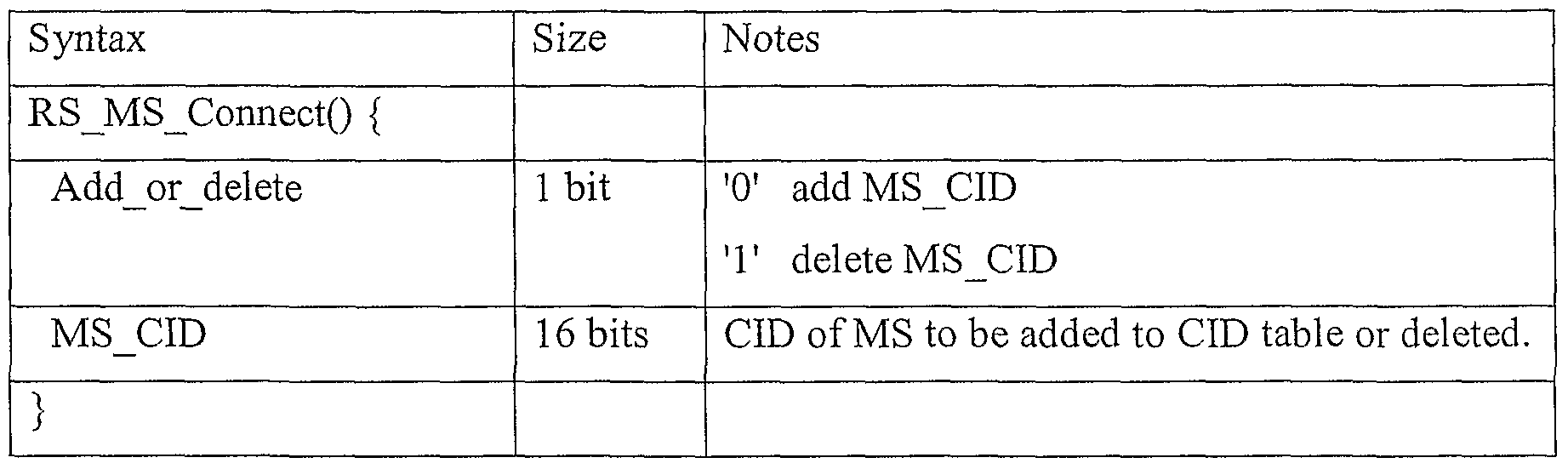
- the relay station which has entered the network needs to identify CIDs of the mobile subscriber stations which perform communication through relay of the relay station.
- the base station determines whether to perform relay communication with the mobile subscriber stations subscribed to the base station through the relay station or to perform direct communication with the mobile subscriber stations. If relay communication through the relay station is required, the base station transmits to the relay station CIDs of the mobile subscriber stations which should perform relay communication through the relay station.
- Table 5 illustrates a CID table indicate message for allowing the base station to transmit CIDs of the mobile subscriber stations which should perform relay communication through the relay station. [Table 5]
- FIG. 11 is a diagram illustrating a frame structure of the base station in the mobile communication system including the relay station.
- the base station transmits a preamble 71 for synchronizing with the relay station (RS) during the nth frame, and also transmits a downlink map message 72 including a first information element 72a and a second information element 72a.
- the first information element has burst allocation information corresponding to the specific relay station during the nth frame. In other words, the first information element has burst allocation information for transmitting data from the base station to the relay station.
- the second information element has burst allocation information corresponding to the specific mobile subscriber station during the (n+l)th frame. In other words, the second information element has burst allocation information for transmitting data from the relay station to the mobile subscriber station.
- Table 6 is an example illustrating the downlink map information element. [Table 6]
- the information element is set to '0' or T so as to identify whether the information element represents the first information element or the second information element. In other words, it is possible to identify whether to represent a burst allocated during the nth frame or a burst allocated during the (n+1 )th frame.
- a burst region 73 allocated to transmit data from the relay station to the mobile subscriber station does not perform signal transmission from the base station to the relay station.
- the region allocated by the second information element during the previous frame to transmit data from the relay station to the mobile subscriber station is not allocated for data transmission from the base station to the relay station during the same frame. This is to avoid collision caused as the burst region is repeatedly allocated for data transmission of the base station and data transmission of the relay station.
- FIG. 12 is an explanatory view illustrating a frame structure of the relay station (RS) in the mobile communication system provided with the relay station (RS).
- the relay station receives a preamble 81 for synchronizing with the relay station (RS) during the nth frame, and also receives a downlink map message 82 including a first
- the first information element has burst allocation information corresponding to the specific relay station during the nth frame. In other words, the first information element has burst allocation information for transmitting data from the base station to the relay station.
- the second information element has burst allocation information corresponding to the specific mobile subscriber station during the (n+l)th frame. In other words, the second information element has burst allocation information for transmitting data from the relay station to the mobile subscriber station. 2
- the relay station identifies burst allocation information for data transmission from the base station to the relay station through the first information element, and receives relay data for the mobile subscriber station through the allocated burst region 83.
- Data transmission from the base station to the relay station is performed during the nth frame.
- the relay station receives the data during the nth frame, decodes the received data, and encodes the decoded data.
- the relay station can identify a burst region 84, which is allocated to transmit the data received during the nth frame, decoded and encoded, through the second information element. Accordingly, the relay station transmits the encoded data to the mobile subscriber station by using the burst region 84 allocated through the second information element. As a result, the burst region 83 allocated to transmit data from the relay station to the mobile subscriber station does not transmit any signal from the base station to the relay station, whereby collision can be avoided.
- the relay station can ensure the time for decoding and encoding the relay data received from the base station.
- one frame has been exemplarily described in the aforementioned embodiment as a delay time for decoding and encoding, data transmission may be performed with delay time more than two frames.
- FIGs. 13A to 13C are explanatory views illustrating a first example of a radio resource allocation method in the mobile communication system provided with the relay station (RS).
- RS relay station
- FIG. 13A is a frame schematic view illustrating radio resource allocation information transmission and a radio resource allocation method.
- FIG. 13A illustrates the operation of the base station in radio resource allocation and radio resource allocation information transmission. Referring to FIG. 13 A, the base station transmits downlink radio resource
- region (region on OFDMA map, hereinafter, referred to as "region") allocation information for transmitting data to the relay station, through a downlink map (DL-MAP) 91 during a T frame.
- the base station transmits downlink data to the relay station through a region 92 allocated by the downlink map (DL-MAP).
- the relay station receives the downlink data transmitted from the base station, and transmits the received data to the mobile subscriber station during a (T+ 1) frame.
- FIG. 13B is a frame schematic view illustrating radio resource allocation information transmission and a radio resource allocation mode.
- FIG. 13B illustrates the operation of the base station in radio resource allocation and radio resource allocation information transmission.
- the relay station receives region allocation information for receiving downlink data transmitted from the base station, through a downlink map (DL- MAP) 95 during the T frame. Also, the relay station receives the downlink data from the base station through a region 96 (corresponding to 92 of FIG. 13A) allocated by the downlink map (DL-MAP) 95. Meanwhile, the relay station receives the downlink data transmitted from the base station, and transmits the received data corresponding to each mobile subscriber station to each mobile subscriber station during the (T+ 1) frame. As described above, the base station does not allocate regions 98a, 98b and 98c for any usage other than usage for transmitting data corresponding to each mobile subscriber station. Accordingly, the relay station can transmit the downlink data corresponding to each mobile subscriber station through the allocated regions 98a, 98b and 98c (corresponding to 94 of FIG. 13A).
- DL- MAP downlink map
- the region information allocated to the mobile subscriber stations is transmitted to the relay station and each mobile subscriber station through a downlink map (DL-MAP) 97 (corresponding to 93 of FIG. 13A).
- region (98a, 98b and 98c) allocation to the mobile subscriber station is performed by the base station. Accordingly, the base station can allocate a region for transmitting data from the base station to the relay station and a region for transmitting data from the relay station to the mobile subscriber station every frame.
- Table 7 illustrates a downlink map information element including a mobile subscriber station where data transmission is relayed by the relay station and region allocation information of each mobile subscriber station.
- Region allocation information of the mobile subscriber station corresponding to each relay station can be transmitted to the relay station through a DL-MAP information element 97 (corresponding to 93 of FIG. 13A) as shown in Table 7.
- FIG. 13C is a frame schematic view illustrating radio resource allocation information transmission and a radio resource allocation mode.
- FIG. 13C illustrates the operation of the mobile subscriber station in radio resource allocation and radio resource allocation information transmission. Referring to FIG. 13 C, the first mobile subscriber
- the data transmitted from the base station during the T frame is transmitted to the mobile subscriber station through the relay station during the (T+ 1) frame. Accordingly, each mobile subscriber station can identify a region allocated to itself by receiving a downlink map 100 (corresponding to 93 of FIG. 13 A and 97 of FIG. 13B) transmitted • during the (T+ 1) frame. As a result, as shown in FIG. 13 C, the first mobile subscriber
- the station allocated with the downlink region can receive the downlink data through the allocated region 81.
- FIGs. 14A to 14C are explanatory views illustrating a second example of a radio resource allocation method in a mobile communication system provided with a relay station (RS).
- RS relay station
- data corresponding to each mobile subscriber station are transmitted through sub-frames.
- a method for allocating a radio resource corresponding to each mobile subscriber station from the relay station in the sub-frames will be described.
- FIG. 14A is a frame schematic view illustrating radio resource allocation information transmission and a radio resource allocation method.
- FIG. 14A illustrates the operation of the base station in radio resource allocation and radio resource allocation information transmission.
- the base station transmits downlink radio resource (region on OFDMA map, hereinafter, referred to as "region") allocation information for transmitting data to the relay station through a downlink map (DL-MAP) 103 during a T frame. Also, the base station transmits downlink data to the relay station through a region 104 allocated by the downlink map (DL-MAP) 103. Meanwhile, the relay station receives the downlink data transmitted from the base station, and transmits the received data to the mobile subscriber station during a (T+ 1) frame.
- region downlink radio resource
- a region 107 for transmitting data from the relay station to the mobile subscriber station is not allocated for any other usage.
- This region allocation information of the (T+ 1) frame is transmitted to the relay station and the mobile subscriber station within the region through a downlink map 106 of the (T+ 1 ) frame.
- FIG. 14B is a frame schematic view illustrating radio resource allocation information transmission and a radio resource allocation mode.
- FIG. 14B illustrates the operation of the relay station in radio resource allocation and radio resource allocation information transmission.
- the relay station receives region allocation information for transmitting data to the relay station, through a downlink map (DL-MAP) 108 during the T frame.
- the relay station receives downlink data from the base station through a region 109 allocated by the downlink map (DL-MAP) 108.
- the relay station receives the downlink data transmitted from the base station, and transmits the received data corresponding to each mobile subscriber station during the (T+ 1) frame.
- DL-MAP downlink map
- the relay station can allocate regions 112b, 112c and 1 12d corresponding to each mobile subscriber station. In other words, the relay station can determine how to allocate regions 112a to 112d (corresponding to 107 of FIG. 14A) allocated from the base station to each mobile subscriber station during the (T+ 1) frame. In order to notify each mobile subscriber station of region information to be allocated to each mobile subscriber station, one 112a of the regions allocated from the base station can be used as a downlink map (DL-MAP) from the relay station to the mobile subscriber station. In other words, the relay station constitutes the region allocated from the base station as a single sub-frame to perform region allocation and region allocation information transmission to each mobile subscriber station.
- DL-MAP downlink map
- the relay station can notify the base station of region allocation information to the mobile subscriber station.
- the relay station can in advance notify the base station of downlink region allocation information to be used for sub-frames 112a to 112d belonging to the next frame ((T+l) frame), through an uplink region (corresponding to 105 of FIG. 14A and 110 of FIG. 14B) allocated to the relay station during the T frame.
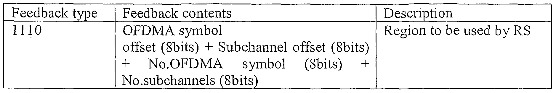
- the relay station may notify the base station of the downlink allocation information by using a feedback header.
- FIG. 15 is a schematic view illustrating the feedback header.
- Table 8 illustrates feedback information for downlink allocation information report according to a feedback header format of FIG. 15. [Table 8]
- the uplink region (corresponding to 105 of FIG. 14A and 110 of FIG. 14B) allocated to the relay station for downlink allocation information report to the mobile subscriber station during the T frame is transmitted through a downlink map (DL-MAP) (corresponding to 102 of FIG. 14A and 113 of FIG. 14B).
- the uplink region allocation information may be transmitted through an information element (RS_Feedback_allocation_IE) included in the downlink map (DL-MAP).
- Table 9 illustrates an example of an information element (RS_Feedback_allocation_IE) having uplink region information allocated to the relay station for downlink allocation information report to the mobile subscriber station. [Table 9]
- the relay station reports the downlink allocation information of the mobile subscriber station to the base station through the uplink region (corresponding to 105 of FIG. 14A and 110 of FIG. 14B) allocated to the relay station as described above. At this time, the downlink allocation information can be transmitted through the feedback header.
- the relay station reports the downlink allocation information of the mobile subscriber station to the base station by using the feedback header during the T frame, and transmits data to each mobile subscriber station through the sub- frame of the (T+ 1) frame.
- the relay station transmits the downlink region information allocated to each mobile subscriber station through the downlink map (DL- MAP) 112a.
- the downlink region is allocated considering the channel status of each mobile subscriber station.
- the data can be transmitted by using DIUC more suitable for each mobile subscriber station.
- Table 10 illustrates an example of the downlink map (DL-MAP) of the sub- frame.
- FIG. 14C is a frame schematic view illustrating radio resource allocation information transmission and a radio resource allocation mode.
- FIG. 14C illustrates the operation of the mobile subscriber station in radio resource allocation and radio resource allocation information transmission.
- FIG. 14C illustrates an example of the first mobile subscriber station receiving data.
- the data transmitted from the base station during the T frame is transmitted to the mobile subscriber station through the relay station during the (T+ 1) frame. Accordingly, each mobile subscriber station can identify a downlink region allocated to itself by receiving a downlink map 116 (corresponding to 112a of FIG. 14B) of the sub-frame transmitted from the relay station during the (T+ 1) frame. As a result, as shown in FIG. 14C, the first mobile subscriber station allocated with the downlink region can receive the downlink data through the allocated region 1 17.
- FIG. 16 is a schematic view illustrating a relay network according to the preferred embodiments of the present invention.
- the base station BS communicates with two mobile subscriber stations MS 1 and MS 3 through a relay station
- FIG. 16 illustrates the mobile subscriber stations which are out of a cell area managed by the base station, technical features of the present invention may be applied to mobile subscriber stations which are within the cell area of the base station and perform communication through the relay station.
- FIGs. 17A to 17D are schematic views illustrating frames transmitted
- FIG. 17A illustrates a structure of an nth frame transmitted and received between the base station BS and the relay stations RS 1 and RS 2. It is apparent that the base station, the relay stations, or other mobile subscriber stations communicating with the base station without through the relay station can transmit and receive data through the nth frame.
- the frame can be defined by a two-dimensional plane of a horizontal axis of a symbol (or time) and a vertical axis of a subchannel (or frequency).
- the whole frame is comprised of a downlink sub-frame (DL sub-frame) and an uplink sub-frame (UL sub-frame).
- the frame should be assigned with a region for performing communication between the relay station and the mobile subscriber station.
- the region is defined as 'relay station region (or RS region)' herein.
- a portion marked by 'RS DL' is a relay station downlink region
- a portion marked by 'RS UL 1 is a relay station uplink region.
- the data transmitted from the base station to the relay station is allocated to the downlink of the frame in a burst mode while the data transmitted from the relay station to the mobile subscriber station is allocated to the relay station downlink region.
- the data are transmitted through the region allocated to the mobile subscriber station from the uplink region indicated by the uplink map (UL-MAP) of the relay station, and the relay station transmits the data received from the mobile subscriber station to the base station through the relay station uplink region (RS UL).
- UL-MAP uplink map
- RS UL relay station uplink region
- the relay station downlink region includes a length of the relay station downlink and uplink map (RS DL/UL MAP), RS-FCH (frame controller header) including coding
- an RS-preamble region for synchronizing with the mobile subscriber station, relay station downlink and uplink map regions, and relay station downlink and uplink data burst regions.
- the RS-preamble may have different sequences per relay station.
- the map structure of the relay station region and burst allocation within the relay station region are determined by the base station.
- the base station includes identification information for identifying the relay station downlink region and the relay station uplink region within the frame, in the downlink map (DL-MAP), and transmits the information to the relay station and the mobile subscriber station, wherein the identification information may be included in the relay station downlink region information element (RS DL Zone IE) and the relay station uplink region information element (RS UL Zone IE).
- RS DL Zone IE relay station downlink region information element
- RS UL Zone IE relay station uplink region information element
- the base station transmits the relay station downlink map (DL-MAP) information and the relay station uplink map (UL-MAP) information to each relay station.
- the relay station downlink map information and the relay station uplink map information include downlink and uplink map information for each mobile subscriber station in the relay station downlink and uplink regions.
- the relay station downlink and uplink map information may include a frame number (for example, (n+l)th frame) which is to transmit data of the mobile subscriber station received from the base station, position information (for example, symbol and subchannel offset value based on the RS-preamble) of RS DL/UL MAP of each relay station, RS DL/UL MAP length, and FCH information including coding information.
- the downlink and uplink map information for each mobile subscriber station includes downlink data burst allocation information and uplink data burst allocation information, wherein the downlink data burst allows each relay station to transmit data to each mobile subscriber station and the uplink data burst allows each mobile subscriber station to transmit data to each relay station.
- the base station may include the relay station downlink and uplink map information in the downlink map (DL-MAP) region and the uplink map (UL-MAP) region along with the downlink and uplink map information allocated to the mobile subscriber station which directly communicates with the base station without through the relay station.
- Each relay station includes the relay station uplink/downlink map information included in the downlink map region and the uplink map region in the relay station downlink map region (RS DL-MAP Zone) and the relay station uplink map region (RS DL-MAP Zone) of
- each mobile subscriber station is allocated with the downlink data burst for receiving data from the relay station and the uplink data burst for transmitting data to the relay station in accordance with the relay station downlink/uplink map information included in the relay station downlink map region (RS DL-MAP Zone) and the relay station uplink map region (RS UL-MAP Zone).
- RS DL-MAP Zone the relay station downlink map region
- RS UL-MAP Zone the relay station uplink map region
- the base station can include the relay station downlink and uplink map information in the data burst allocated to each relay station and then can transmit the map information to each relay station.
- the base station allocates the data burst of each relay station to the downlink data burst region and transmits the data through the allocated data burst.
- a region 'A' represents a data burst including data to be transmitted from the base station to the mobile subscriber stations MS 1 and MS 3 through the relay station RS 1 and is allocated to the relay station RS I 3 and a region 'B' represents a data burst including data to be transmitted from the base station to the mobile subscriber station MS 2 through the relay station RS 2 and is allocated to the relay station RS 2.
- the data bursts A and B respectively allocated to the relay stations RS 1 and RS 2 include the relay station downlink and uplink map (RSl DL/UL-MAP and RS2 DL/UL-MAP) information along with the data to be transmitted to the mobile subscriber stations.
- the base station designates the positions of the data bursts A and B allocated to the relay stations RS 1 and RS 2 and a frame number for transmitting data to the mobile subscriber station in the relay stations RS 1 and RS 2 through the DL-MAP information element (IE) of the downlink map (DL-MAP) region.
- IE DL-MAP information element
- the relay stations RS 1 and RS 2 identify the positions of the data bursts A and B allocated thereto through the DL-MAP information element, and transmit the relay station downlink region to the mobile subscriber station by using the relay station downlink and uplink map (RSl DL/UL-MAP and RS2 DL/UL-MAP) information included in their corresponding data bursts.
- the relay station downlink and uplink map RSl DL/UL-MAP and RS2 DL/UL-MAP
- FIG. 17B illustrates a structure of a frame ((n+l)th frame) designated by the base station to allow the relay station RS 1 to transmit the data to the mobile subscriber stations
- the relay station RS 1 includes the relay station downlink and uplink map (RS 1 DL/UL-MAP) information in the RSl UL-MAP region and RSl DL-MAP region of the relay station downlink region, wherein the relay station downlink and uplink map (RSl DL/UL-MAP) information is included in the data burst A allocated from the base station to the relay station RS 1.
- RS 1 DL/UL-MAP relay station downlink and uplink map
- the relay station RS 1 includes data to be transmitted to respective mobile subscriber stations MS 1 and MS 3 in data bursts C and D for the respective mobile subscriber stations MS 1 and MS 3 indicated by the relay station downlink and uplink map information and then transmits the data. Since the relay station downlink and uplink map (RSl DL/UL-MAP) information for each relay station is transmitted through the data bursts for each relay station, relay station downlink and uplink map (RSl DL/UL-MAP) information for other relay station is not included repeatedly in UL-MAP or DL-MAP region of the relay station.
- the mobile subscriber stations MS 1 and MS 3 synchronize with the relay station RS 1 through the RS-preamble of the (n+l)th frame of FIG. 17B, identify the positions of the data bursts C and D allocated from the relay station downlink map (RSl DL-MAP) information included in the RSl UL-MAP region of the relay station downlink region, and receive the data.
- RSl DL/UL-MAP
- FIG. 17C illustrates a structure of the frame ((n+l)th frame) designated by the base station to allow the relay station RS 2 to transmit data to the mobile subscriber station MS 2.
- the relay station RS 2 includes relay station downlink and uplink map (RS2 DL/UL- MAP) information included in the data burst B allocated from the base station in RS2 UL- MAP region and RS2 DL-MAP region of the relay station downlink region, and includes the data to be transmitted to the mobile subscriber station MS 2 in a data burst E for the mobile subscriber station MS 2 indicated by the relay station downlink and uplink map information.
- RS2 DL/UL- MAP relay station downlink and uplink map
- the mobile subscriber station MS 2 synchronizes with the relay station RS 2 through the RS-preamble of the (n+l)th frame of FIG. 17C, identifies the position of the data burst E allocated from the relay station downlink map (RS2 DL-MAP) information included in the RS2 UL-MAP region of the relay station downlink region, and receives the data.
- a region 'F' represents an uplink data burst allocated to the mobile subscriber station MS 2.
- FIG. 17D illustrates a structure of a frame ((n+2)th frame) designated by the
- FIGs. I SA and 18B are schematic views illustrating a frame structure according to the preferred embodiments of the present invention.
- FIGs. 18A and 18B respectively illustrate the nth frame transmitted and received between the base station BS and the relay stations RS 1 and RS 2, and the (n+l)th frame transmitted from the relay station RS 1 to the mobile subscriber stations MS 1 and MS 3.
- the base station transmits the relay station downlink and uplink map information included in the data bursts to the relay station in the same manner as the embodiment shown in FIG. 17A.
- the base station transmits the relay station downlink and uplink map information included in the data burst to which the data transmitted to each relay station is allocated
- the base station transmits the relay station downlink and uplink map information through a data burst different from the data burst to which the data transmitted to each relay station is allocated.
- the relay station downlink and uplink map information for each relay station may be transmitted through a separate data burst.
- the relay station downlink and uplink map information for two or more relay stations may be transmitted through a single data burst.
- the relay station downlink and uplink map information for all the relay stations may be transmitted through a single data burst.
- the base station should notify each relay station of the position of the burst to which the relay station downlink and uplink map information is allocated, wherein the relay station downlink and uplink map information is allocated to each relay station through the relay station map information (RS-MAP info) IE included in the downlink map
- RS-MAP info relay station map information
- DL-MAP Downlink Mobile Network
- a data burst based on a broadcast CID is preferably used.
- a region "H " represents a data burst including the relay station downlink and uplink map information for all the relay stations.
- each relay station should recognize the position of data burst including the relay station downlink and uplink map information allocated from the DL-MAP region included in the nth frame and the position of the data burst including the data to be transmitted to the mobile subscriber station so as to receive the relay station downlink and uplink map information and the data to be transmitted to the mobile subscriber station.
- the relay station RS 1 transmits the relay station downlink and uplink map (RSl DL/UL-MAP) information and the data to be transmitted to each mobile subscriber station by including the relay station downlink and uplink map (RS 1 DL/UL-MAP) information in the RS 1 UL-MAP region and the RS 1 DL-MAP region of the relay station downlink region, wherein the relay station downlink and uplink map (RSl DL/UL-MAP) information is included in the data burst H including the relay station downlink and uplink map information, and also including the data to be transmitted to each mobile subscriber station in data bursts I and J for the respective mobile subscriber stations MS 1 and MS 3 indicated by the relay station downlink and uplink map information.
- the mobile subscriber stations MS 1 and MS 3 synchronize with the relay station RS 1 through
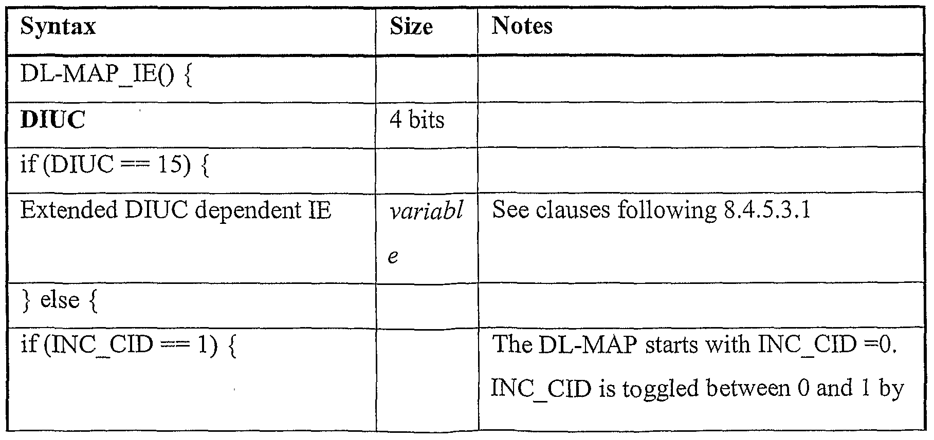
- Table 1 1 illustrates an example of a data format of the downlink map information element (DL-MAP IE) for allowing the base station to indicate the relay station on the position of the burst including the relay station downlink and uplink map information.
- DL-MAP IE downlink map information element
- Table 12 and Table 13 define a new DIUC type (extended DIUC) for an information element indicating the position of the burst including the relay station downlink and uplink map information. [Table 12]
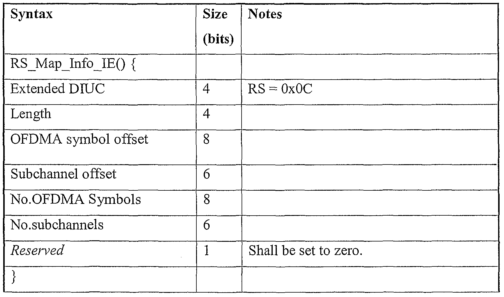
- Table 14 illustrates an example of a data format of the relay station downlink map information element (RS MAP_Info IE) for allowing the base station to indicate the relay station on the position of the burst including the relay station downlink and uplink map information.
- RS MAP_Info IE relay station downlink map information element
- Table 14 illustrates an example of a data format of the relay station downlink map information element (RS MAP_Info IE) for allowing the base station to indicate the relay station on the position of the burst including the relay station downlink and uplink map information.
- DIUC is ' 15' and 'Extended DIUC dependent IE' field is 1 OC/
- the relay station reads out the RS MAPJnfo IE of Table 14 referring to DL-MAP IE of Table 3 to identify the position of the burst including the relay station downlink and uplink map information.
- the position of the burst is designated by subchannel offset, symbol offset, the number of subchannels, and the number of symbols in Table 14, it
- FIG. 19 is a schematic view illustrating a frame structure suggested for communication through the relay station.
- a portion 'RS DL' represents a downlink relay station region while a portion 'RS UL' represents an uplink relay station region.
- the data transmitted from the base station to the relay station is allocated to the downlink of the existing frame in a burst mode while the data transmitted from the relay station to the mobile subscriber station is allocated to the downlink relay station region.
- the data is transmitted through the region allocated to the mobile subscriber station from the uplink region indicated by the uplink map (UL-MAP) of the relay station, and the relay station transmits the data received from the mobile subscriber station to the base station through the uplink relay station region (RS UL).
- the downlink relay station region includes a length of the relay station downlink and uplink map (RS DL/UL MAP), RS-FCH (frame controller header) including coding
- an RS-preamble region for synchronizing with the mobile subscriber station, relay station downlink and uplink map regions, and relay station downlink and uplink data burst regions.
- the RS-preamble may have different sequences per relay station.
- the map structure of the relay station region and burst allocation within the relay station region are determined by the base station.
- FIGs. 20 and 21 are schematic views illustrating frames transmitted and received from the base station and the relay station to the mobile subscriber station in accordance with the preferred embodiment of the present invention.
- FIG. 20 illustrates a structure of the nth frame transmitted and received between the base station and the relay stations RS 1 and RS 2.
- the frame can be defined by a two-dimensional plane of a horizontal axis of a symbol (or time) and a vertical axis of a subchannel (or frequency).
- the whole frame is comprised of a downlink sub-frame (DL sub-frame) and an uplink sub- frame (UL sub-frame).
- the base station includes identification information for designating the downlink and uplink relay station regions within the frame, in the downlink map (DL-MAP), and transmits the identification information to the relay station and the mobile subscriber station, wherein the identification information may be included in the relay station downlink region information element (RS DL Zone IE) and the relay station uplink region information element (RS UL Zone IE).
- RS DL Zone IE relay station downlink region information element
- RS UL Zone IE relay station uplink region information element
- the identification information for the relay station region includes identification information of a start point of the relay station region. Also, the identification information may include identification information of a start point of the relay station region during at least one next frame as well as identification information of a start point of the relay station region during the current frame. In FIG. 20, the start point of the relay station region represents a start point of the relay station preamble (RS-preamble).
- the information for the relay station region may be included in the data bursts A and B allocated to each relay station.
- the positions of the data bursts allocated to each relay station are designated by a message included in the downlink map (DL-MAP) region of the frame.
- DL-MAP downlink map
- the base station transmits the relay station downlink map (RS DL-MAP) information and the relay station uplink map (RS UL-MAP) information to each relay station.
- the relay station downlink map information and the relay station uplink map information include a frame number (for example, (n+l)th frame) which is to transmit data of the mobile subscriber station received from the base station, position information (for example, symbol and subchannel offset value based on the RS-preamble) of RS DLAJL MAP of each relay station, RS DL/UL MAP length, FCH information including coding information, and downlink and uplink map information for each mobile subscriber station in the downlink and uplink relay station regions.
- a frame number for example, (n+l)th frame
- position information for example, symbol and subchannel offset value based on the RS-preamble
- FCH information including coding information
- downlink and uplink map information for each mobile subscriber station in the downlink and uplink relay station regions.
- the downlink and uplink map information for each mobile subscriber station includes downlink data burst allocation information and uplink data burst allocation information, wherein the downlink data burst allows each relay station to transmit data to each mobile subscriber station and the uplink data burst allows each mobile subscriber station to transmit data to each relay station.
- the base station may include the relay station downlink and uplink map information in the downlink map (DL-MAP) region and the uplink map (UL-MAP) region along with the downlink and uplink map information allocated to the mobile subscriber station which directly communicates with the base station, without through the relay station.
- Each relay station includes the relay station uplink/downlink map information included in the downlink map region and the uplink map region in the relay station downlink map region (RS DL-MAP Zone) and the relay station uplink map region (RS DL-MAP Zone) of the downlink relay station region (RS DL) or the uplink relay station region (RS UL), and then transmits the map information to the mobile subscriber station.
- Each mobile subscriber station is allocated with the downlink data burst for receiving data from the relay station and the uplink data burst for transmitting data to the relay station in accordance with the relay station downlink/uplink map information included in the relay station downlink map region (RS DL-MAP Zone) and the relay station uplink map region (RS UL-MAP Zone).
- RS DL-MAP Zone relay station downlink map region
- RS UL-MAP Zone relay station uplink map region
- the base station can include the relay station downlink and uplink map information in the data burst allocated to each relay station and then can transmit the map information to each relay station.
- the base station allocates the data burst of each relay station to the downlink data burst
- a region 'A' represents a data burst including data to be transmitted from the base station to the mobile subscriber stations MS 1 and MS 3 through the relay station RS 1 and is allocated to the relay station RS 1
- a region 'B' represents a data burst including data to be transmitted from the base station to the mobile subscriber station MS 2 through the relay station RS 2 and is allocated to the relay station RS 2.
- the data bursts A and B respectively allocated to the relay stations RS 1 and RS 2 include the relay station downlink and uplink map (RSl DL/UL-MAP and RS2 DL/UL-MAP) information along with the data to be transmitted to the mobile subscriber stations.
- the base station designates the positions of the data bursts A and B allocated to the relay stations RS 1 and RS 2 and a frame number for transmitting data to the mobile subscriber station in the relay stations RS 1 and RS 2 through the DL-MAP information element (IE) of the downlink map (DL-MAP) region.
- IE DL-MAP information element
- the relay stations RS 1 and RS 2 identify the positions of the data bursts A and B allocated thereto through the DL-MAP information element, and transmit the downlink relay station region to the mobile subscriber station by using the relay station downlink and uplink map (RSl DL/UL-MAP and RS2 DL/UL-MAP) information included in their corresponding data bursts.
- the relay station downlink and uplink map RSl DL/UL-MAP and RS2 DL/UL-MAP
- FIG. 21 illustrates a structure of a frame ((n+l)th frame) designated by the base station to allow the relay station RS 1 to transmit the data to the mobile subscriber stations MS 1 and MS 3, i.e., a structure of the (n+l)th frame transmitted from the relay station RS 1 to the mobile subscriber stations MS 1 and MS 3.
- the relay station RS 1 includes the relay station downlink and uplink map (RSl DL/UL-MAP) information in the RSl UL-MAP region and the RSl DL-MAP region of the relay station downlink region, wherein the relay station downlink and uplink map (RSl DL/UL-MAP) information is included in the data burst A allocated from the base station to the relay station RS 1.
- RSl DL/UL-MAP relay station downlink and uplink map
- the relay station RS 1 includes data to be transmitted to respective mobile subscriber stations MS 1 and MS 3 in data bursts C and D for the respective mobile subscriber stations MS 1 and MS 3 indicated by the relay station downlink and uplink map information. Then, the relay station RS 1 transmits the map information and the data. The relay station RS 1 transmits a message including the identification information for the relay station region to the mobile subscriber station through the relay
- the identification information for the relay station region includes identification information of a start point of the relay station region during at least one next frame as well as identification information of a start point of the relay station region during the current frame.
- the start point of the relay station region represents a start point of the relay station preamble (RS-preamble).
- Table 15 illustrates an example of a data format of a message (RSL DL-MAP message) including identification information of the start point of the relay station preamble.
- identification information of the start point of the relay station preamble is expressed by a 'Current Preamble Offset' field and a 'Next Preamble Offset' field.
- the 'Current Preamble Offset' field means symbol offset from a specific reference point to the start point of the current relay station preamble (RS-preamble)
- the 'Next Preamble Offset' field means symbol offset from a specific reference point to the start point of the relay station preamble during the next frame.
- the specific reference point preferably corresponds to the symbol position of the message including the identification information of the start point of the relay station preamble, it is not limited to such position.
- the identification information of the start point of the relay station preamble may be expressed by various methods in addition to the example of Table 15.
- the 'Current Preamble Offset' field may mean symbol offset from a specific reference point to the start point of the current relay station preamble (RS-preamble)
- the 'Next Preamble Offset' field may mean symbol offset from the start point of the relay station preamble during the current frame to the start point of the relay station preamble during the next frame.
- the identification information may include the 'Next Preamble Offset' only.
- the identification information may designate the start point of the relay station preamble during a single next frame after the current frame
- the identification information may designate the start point of the relay station preamble during two or more next frames. Since the mobile subscriber station can easily retrieve the start point of the relay station preamble from the identification information during the next frame, there is no need to synchronize with the relay station preamble to retrieve the relay station region for every frame, and the start point of the relay station region can be retrieved quickly and exactly even in the case that the position of the relay station region is varied.
- the communication method using the relay station in the mobile communication system according to the present invention has the following
- the data can be transmitted to mobile subscriber stations corresponding to a shadow area by relay communication, and higher throughput can be supported to mobile subscriber stations not corresponding to the shadow area.
- the communication resource allocation procedure can clearly be defined and the communication resource can efficiently be allocated.
- the mobile subscriber station does not need to synchronize with the relay station preamble to retrieve the relay station region for every frame, and the start point of the relay station region can be retrieved quickly and exactly even in the case that the position of the relay station region is varied.
- the present invention can be applied to the mobile communication system such as a cellular mobile communication system and a wireless Internet system.
Abstract
Description


Claims
Priority Applications (7)
| Application Number | Priority Date | Filing Date | Title |
|---|---|---|---|
| CA2631421A CA2631421C (en) | 2005-12-13 | 2006-12-13 | Communication method using relay station in mobile communication system |
| US12/097,228 US9042293B2 (en) | 2005-12-13 | 2006-12-13 | Communication method using relay station in mobile communication system |
| AU2006325632A AU2006325632B2 (en) | 2005-12-13 | 2006-12-13 | Communication method using relay station in mobile communication system |
| BRPI0620674-3A BRPI0620674A2 (en) | 2005-12-13 | 2006-12-13 | communication method using relay station in a mobile communication system |
| CN2006800468706A CN101512965B (en) | 2005-12-13 | 2006-12-13 | Communication method using relay station in mobile communication system |
| EP20060824136 EP1969882B1 (en) | 2005-12-13 | 2006-12-13 | Communication method using relay station in mobile communication system |
| JP2008544265A JP4751451B2 (en) | 2005-12-13 | 2006-12-13 | Communication method using relay station in wireless communication system |
Applications Claiming Priority (8)
| Application Number | Priority Date | Filing Date | Title |
|---|---|---|---|
| KR10-2005-0122523 | 2005-12-13 | ||
| KR1020050122523A KR101108055B1 (en) | 2005-12-13 | 2005-12-13 | Realy Method for Data Transmission |
| KR10-2006-0011622 | 2006-02-07 | ||
| KR1020060011622A KR101079101B1 (en) | 2006-02-07 | 2006-02-07 | Method for Relay Communication Using Relay Station |
| KR1020060020139A KR101162212B1 (en) | 2006-03-02 | 2006-03-02 | Communication method via relay station and data frame therefor in mobile communications system |
| KR10-2006-0020139 | 2006-03-02 | ||
| KR10-2006-0030216 | 2006-04-03 | ||
| KR1020060030216A KR101208521B1 (en) | 2006-04-03 | 2006-04-03 | Method of allocating and searching relay station region in mobile communications system |
Publications (2)
| Publication Number | Publication Date |
|---|---|
| WO2007069848A2 true WO2007069848A2 (en) | 2007-06-21 |
| WO2007069848A3 WO2007069848A3 (en) | 2009-05-14 |
Family
ID=38163347
Family Applications (1)
| Application Number | Title | Priority Date | Filing Date |
|---|---|---|---|
| PCT/KR2006/005432 WO2007069848A2 (en) | 2005-12-13 | 2006-12-13 | Communication method using relay station in mobile communication system |
Country Status (7)
| Country | Link |
|---|---|
| US (1) | US9042293B2 (en) |
| EP (1) | EP1969882B1 (en) |
| JP (1) | JP4751451B2 (en) |
| AU (1) | AU2006325632B2 (en) |
| BR (1) | BRPI0620674A2 (en) |
| CA (1) | CA2631421C (en) |
| WO (1) | WO2007069848A2 (en) |
Cited By (22)
| Publication number | Priority date | Publication date | Assignee | Title |
|---|---|---|---|---|
| JP2007201848A (en) * | 2006-01-27 | 2007-08-09 | Kddi Corp | Ranging method through relay station in ieee802.16, program, and system |
| JP2008048366A (en) * | 2006-08-21 | 2008-02-28 | Fujitsu Ltd | Radio base station |
| WO2009054690A2 (en) * | 2007-10-23 | 2009-04-30 | Electronics And Telecommunications Research Institute | Method for transmitting signals |
| WO2009066899A2 (en) * | 2007-11-21 | 2009-05-28 | Lg Electronics Inc. | Method for communicating with relay station |
| JP2009188537A (en) * | 2008-02-04 | 2009-08-20 | Fujitsu Ltd | Base station and known signal transmitting method |
| JP2010050853A (en) * | 2008-08-23 | 2010-03-04 | Kyocera Corp | Relay station, and radio communication relay method |
| WO2010032973A2 (en) * | 2008-09-18 | 2010-03-25 | 엘지전자주식회사 | Method and apparatus for data relay in a multi-hop system |
| WO2010041835A3 (en) * | 2008-10-10 | 2010-06-24 | Lg Electronics Inc. | Method for transmitting reference signals for relay node |
| WO2010093143A2 (en) * | 2009-02-11 | 2010-08-19 | 엘지전자주식회사 | Method and apparatus for relaying data in wireless communication system |
| US20100248619A1 (en) * | 2007-01-12 | 2010-09-30 | Nortel Networks Limited | Mobile relay communication system |
| CN101917768A (en) * | 2010-08-25 | 2010-12-15 | 中国科学技术大学 | User fairness resource allocation method for orthogonal frequency division multiple access relay system |
| WO2011019168A2 (en) * | 2009-08-13 | 2011-02-17 | Samsung Electronics Co., Ltd. | Method and apparatus for transmitting reference signals in communication systems |
| CN102204136A (en) * | 2008-10-30 | 2011-09-28 | 北方电讯网络有限公司 | Relay techniques suitable for user equipment in downlink |
| KR101117895B1 (en) * | 2007-06-29 | 2012-02-24 | 모토로라 솔루션즈, 인크. | Method of communication scheduling in a multihop network |
| US8675600B2 (en) | 2007-10-23 | 2014-03-18 | Samsung Electronics Co., Ltd. | Method for transmitting signals |
| JP2014090478A (en) * | 2008-02-13 | 2014-05-15 | Qualcomm Incorporated | System and method for scheduling over multiple hops |
| KR101489517B1 (en) * | 2008-09-18 | 2015-02-06 | 엘지전자 주식회사 | Apparatus and method of data relay in multi-hop system |
| US8976806B2 (en) | 2009-08-14 | 2015-03-10 | Interdigital Technology Corporation | DL backhaul control channel design for relays |
| JP2015159570A (en) * | 2007-11-16 | 2015-09-03 | クゥアルコム・インコーポレイテッドQualcomm Incorporated | Preamble design for wireless signal |
| US9801188B2 (en) | 2008-02-01 | 2017-10-24 | Qualcomm Incorporated | Backhaul signaling for interference avoidance |
| WO2017215766A1 (en) * | 2016-06-17 | 2017-12-21 | Sony Mobile Communications Inc. | Allocating radio resources in backhaul and access link |
| CN110831187A (en) * | 2018-08-10 | 2020-02-21 | 成都华为技术有限公司 | Resource allocation method and device |
Families Citing this family (43)
| Publication number | Priority date | Publication date | Assignee | Title |
|---|---|---|---|---|
| US8363744B2 (en) | 2001-06-10 | 2013-01-29 | Aloft Media, Llc | Method and system for robust, secure, and high-efficiency voice and packet transmission over ad-hoc, mesh, and MIMO communication networks |
| KR100901137B1 (en) * | 2006-01-03 | 2009-06-04 | 삼성전자주식회사 | Method and apparatus for managing connection identifier in a multi-hop relay wireless access communication system |
| KR100975732B1 (en) * | 2006-08-31 | 2010-08-12 | 삼성전자주식회사 | Method and system transmitting resource allocation information in a communication system |
| KR100930047B1 (en) * | 2007-01-12 | 2009-12-08 | 삼성전자주식회사 | Dynamic Channel Allocation Apparatus and Method in Multi-channel Wireless Communication Systems |
| KR100949287B1 (en) * | 2007-01-25 | 2010-03-25 | 삼성전자주식회사 | Apparatus and method for processing bandwidth request in a multi-hop relay broadband wireless access communication system |
| JP4880496B2 (en) * | 2007-02-23 | 2012-02-22 | 京セラ株式会社 | Wireless communication system, wireless communication terminal, wireless base station, and wireless communication method |
| WO2008146469A1 (en) * | 2007-05-22 | 2008-12-04 | Panasonic Corporation | Mobile communication system, radio communication relay station device, and relay transmission method |
| WO2008147150A1 (en) * | 2007-05-30 | 2008-12-04 | Electronics And Telecommunications Research Institute | Radio resource reallocating method for circuit mode |
| EP2111005A1 (en) * | 2007-06-18 | 2009-10-21 | Mitsubishi Electric R&D Centre Europe B.V. | Method for allocating, by a telecommunication device, at least a channel element of a group of channel elements of a channel resource to a destination |
| KR101015681B1 (en) * | 2007-07-16 | 2011-02-22 | 삼성전자주식회사 | Method and apparatus for allocating bandwidth in a communication system |
| KR100956726B1 (en) * | 2007-07-20 | 2010-05-06 | 삼성전자주식회사 | Reray for detecting error in asynchronous received data and map information |
| US8503374B2 (en) * | 2007-08-02 | 2013-08-06 | Qualcomm Incorporated | Method for scheduling orthogonally over multiple hops |
| US9699688B2 (en) * | 2007-08-02 | 2017-07-04 | Qualcomm Incorporated | Method for scheduling orthogonally over multiple hops |
| WO2009035263A1 (en) * | 2007-09-10 | 2009-03-19 | Electronics And Telecommunications Research Institute | Method for allocating resource and receiving data |
| US20090122744A1 (en) * | 2007-11-09 | 2009-05-14 | Alexander Maltsev | Selective relaying for wireless networks |
| KR100969147B1 (en) * | 2007-11-29 | 2010-07-08 | 한국전자통신연구원 | Method and system for operating cooperative receive diversity, selective cooperative relaying |
| JP5122264B2 (en) * | 2007-12-18 | 2013-01-16 | 京セラ株式会社 | COMMUNICATION METHOD AND BASE STATION DEVICE AND TERMINAL DEVICE USING THE SAME |
| KR101529852B1 (en) | 2008-01-02 | 2015-07-01 | 인터디지탈 테크날러지 코포레이션 | Method and apparatus for cooperative wireless communications |
| KR101433948B1 (en) * | 2008-03-05 | 2014-08-26 | 삼성전자주식회사 | System and method for transmitting/receiving a signal in a communication system |
| US8995548B2 (en) * | 2008-03-10 | 2015-03-31 | Google Technology Holdings LLC | Method and apparatus for channel sounding in an orthogonal frequency division multiplexing communication system |
| JP5251191B2 (en) * | 2008-03-19 | 2013-07-31 | 富士通株式会社 | Mobile communication terminal device and communication control method |
| US20090257392A1 (en) * | 2008-04-14 | 2009-10-15 | Futurewei Technologies, Inc. | System and Method for Efficiently Packing Two-Dimensional Data Bursts in a Downlink of a Wireless Communications System |
| JP5127588B2 (en) * | 2008-06-23 | 2013-01-23 | 株式会社エヌ・ティ・ティ・ドコモ | User apparatus, base station apparatus and communication method in mobile communication system |
| EP2306661B1 (en) * | 2008-07-30 | 2015-02-25 | LG Electronics Inc. | Relay station in radio communication system and operating method for the relay station |
| EP2326028B1 (en) * | 2008-09-11 | 2014-04-09 | Fujitsu Limited | Radio relay system, radio frame utilizing method and setting method |
| US8139535B2 (en) * | 2008-10-31 | 2012-03-20 | Intel Corporation | Blind channel detection techniques |
| US8848594B2 (en) | 2008-12-10 | 2014-09-30 | Blackberry Limited | Method and apparatus for discovery of relay nodes |
| US8040904B2 (en) | 2008-12-17 | 2011-10-18 | Research In Motion Limited | System and method for autonomous combining |
| US8355388B2 (en) * | 2008-12-17 | 2013-01-15 | Research In Motion Limited | System and method for initial access to relays |
| US8402334B2 (en) | 2008-12-17 | 2013-03-19 | Research In Motion Limited | System and method for hybrid automatic repeat request (HARQ) functionality in a relay node |
| US8311061B2 (en) * | 2008-12-17 | 2012-11-13 | Research In Motion Limited | System and method for multi-user multiplexing |
| US8265128B2 (en) * | 2008-12-19 | 2012-09-11 | Research In Motion Limited | Multiple-input multiple-output (MIMO) with relay nodes |
| US8335466B2 (en) | 2008-12-19 | 2012-12-18 | Research In Motion Limited | System and method for resource allocation |
| US8446856B2 (en) | 2008-12-19 | 2013-05-21 | Research In Motion Limited | System and method for relay node selection |
| EP2416618A4 (en) * | 2009-03-31 | 2017-01-25 | Fujitsu Limited | Relay station, base station, method of relaying, and communication method in wireless communication network |
| WO2010134162A1 (en) * | 2009-05-19 | 2010-11-25 | 富士通株式会社 | Base station, relay station, communication system, and communication method |
| WO2011052022A1 (en) * | 2009-11-02 | 2011-05-05 | 株式会社日立製作所 | Wireless communication system having relay device, and method for selecting relay terminal |
| CN102215570B (en) * | 2010-04-02 | 2016-04-13 | 中兴通讯股份有限公司 | The instruction of backhaul link boundary and defining method, base station |
| KR101678814B1 (en) * | 2010-04-12 | 2016-11-23 | 삼성전자주식회사 | Method and apparatus for supporting cooperative handover in broadband wireless communication system |
| KR20120012749A (en) * | 2010-08-03 | 2012-02-10 | 한국전자통신연구원 | Method and apparatus for distributed scheduling in wireless mesh network based on ofdma |
| KR20120016388A (en) * | 2010-08-16 | 2012-02-24 | 삼성전자주식회사 | Apparatus and method for body information acquisition in portable terminal |
| JP5397490B2 (en) * | 2012-01-30 | 2014-01-22 | 富士通株式会社 | Radio relay communication method and radio relay station in radio communication system |
| CN117278090B (en) * | 2023-11-22 | 2024-03-01 | 广州天奕技术股份有限公司 | Repeater management system, control method, device, equipment and readable storage medium |
Citations (1)
| Publication number | Priority date | Publication date | Assignee | Title |
|---|---|---|---|---|
| WO2005067173A1 (en) | 2003-12-30 | 2005-07-21 | Nokia Corporation | Communication system using relay base stations with asymmetric data links |
Family Cites Families (24)
| Publication number | Priority date | Publication date | Assignee | Title |
|---|---|---|---|---|
| CN1196367C (en) | 1998-02-27 | 2005-04-06 | 西门子公司 | Relaying in a telecommunications system based on code and time-division multiplex |
| JP2002508620A (en) * | 1998-03-23 | 2002-03-19 | サムスン エレクトロニクス カンパニー リミテッド | Power control apparatus and method for reverse link common channel in code division multiple access communication system |
| JP2003504543A (en) | 1999-07-07 | 2003-02-04 | フライト・リフュエリング・リミテッド | Data transmission in pipeline systems |
| EP1100228A3 (en) * | 1999-11-09 | 2009-03-25 | Panasonic Corporation | Data transmission method and system, and device used therefor |
| DE60128132T2 (en) * | 2000-12-11 | 2007-12-27 | Sharp K.K. | RADIO COMMUNICATION SYSTEM |
| US8099095B2 (en) * | 2003-02-25 | 2012-01-17 | Qualcomm Incorporated | Method and apparatus for controlling operation of an access terminal in a communication system |
| US20070167994A1 (en) * | 2003-12-12 | 2007-07-19 | Advanced Bioics Corporation | Telemetry method and apparatus for ambulatory medical device |
| US20090258639A1 (en) * | 2003-12-19 | 2009-10-15 | Nystroem Johan | Method, system and device for providing a robust wireless connection |
| KR100973946B1 (en) | 2004-03-12 | 2010-08-05 | 삼성전자주식회사 | System and method for operation band adaptive modulation and coding subchannel in a orthogonal frequency division multiple access system |
| KR100754658B1 (en) * | 2004-03-12 | 2007-09-03 | 삼성전자주식회사 | Method for operation of hybrid automatic repeat request in a broadband wireless communication system |
| CA2557535C (en) * | 2004-03-12 | 2012-05-15 | Samsung Electronics Co., Ltd. | Method and apparatus for constructing map ie using reduced cid in broadband ofdma systems |
| DE102004015897B3 (en) | 2004-03-31 | 2005-12-15 | Siemens Ag | Method for allocating radio resources for a WLAN |
| EP1766806B1 (en) * | 2004-06-22 | 2017-11-01 | Apple Inc. | Closed loop mimo systems and methods |
| EP2442513A1 (en) * | 2004-06-24 | 2012-04-18 | Nortel Networks Limited | Preambles in OFDMA System |
| KR101053610B1 (en) | 2004-06-25 | 2011-08-03 | 엘지전자 주식회사 | Radio resource allocation method of OPDM / OPDM system |
| US7773535B2 (en) * | 2004-08-12 | 2010-08-10 | Motorola, Inc. | Method and apparatus for closed loop transmission |
| KR100725773B1 (en) * | 2004-08-20 | 2007-06-08 | 삼성전자주식회사 | Apparatus and method for adaptively changing the uplink power control scheme depending on the status of mobile station in a wireless mobile communication system using time division duplexing scheme |
| JP4494134B2 (en) * | 2004-09-01 | 2010-06-30 | Kddi株式会社 | Wireless communication system, relay station apparatus and base station apparatus |
| US7853204B2 (en) * | 2004-10-21 | 2010-12-14 | Panasonic Corporation | Method and system for identifying a relay mobile station in a wireless communication network |
| KR100584409B1 (en) * | 2004-12-29 | 2006-05-26 | 삼성전자주식회사 | Relay commonication method for ofdma-based cellular communication system |
| EP1872535A1 (en) * | 2005-04-21 | 2008-01-02 | Nokia Corporation | Supporting a transmission and a reception of data packets |
| US7813695B2 (en) * | 2005-05-06 | 2010-10-12 | Telefonaktiebolaget L M Ericsson (Publ) | Mobile assisted relay selection in a telecommunications system |
| US8731562B2 (en) * | 2005-08-30 | 2014-05-20 | Telefonaktiebolaget L M Ericsson (Publ) | Detection of control messages for HSDPA |
| US7542439B2 (en) * | 2005-09-09 | 2009-06-02 | Intel Corporation | Methods and apparatus for providing a cooperative relay system associated with a broadband wireless access network |
-
2006
- 2006-12-13 BR BRPI0620674-3A patent/BRPI0620674A2/en not_active IP Right Cessation
- 2006-12-13 CA CA2631421A patent/CA2631421C/en not_active Expired - Fee Related
- 2006-12-13 AU AU2006325632A patent/AU2006325632B2/en not_active Ceased
- 2006-12-13 JP JP2008544265A patent/JP4751451B2/en not_active Expired - Fee Related
- 2006-12-13 EP EP20060824136 patent/EP1969882B1/en not_active Not-in-force
- 2006-12-13 US US12/097,228 patent/US9042293B2/en not_active Expired - Fee Related
- 2006-12-13 WO PCT/KR2006/005432 patent/WO2007069848A2/en active Application Filing
Patent Citations (1)
| Publication number | Priority date | Publication date | Assignee | Title |
|---|---|---|---|---|
| WO2005067173A1 (en) | 2003-12-30 | 2005-07-21 | Nokia Corporation | Communication system using relay base stations with asymmetric data links |
Cited By (46)
| Publication number | Priority date | Publication date | Assignee | Title |
|---|---|---|---|---|
| JP2007201848A (en) * | 2006-01-27 | 2007-08-09 | Kddi Corp | Ranging method through relay station in ieee802.16, program, and system |
| JP2008048366A (en) * | 2006-08-21 | 2008-02-28 | Fujitsu Ltd | Radio base station |
| US20100248619A1 (en) * | 2007-01-12 | 2010-09-30 | Nortel Networks Limited | Mobile relay communication system |
| US8843058B2 (en) * | 2007-01-12 | 2014-09-23 | Blackberry Limited | Mobile relay communication system |
| KR101117895B1 (en) * | 2007-06-29 | 2012-02-24 | 모토로라 솔루션즈, 인크. | Method of communication scheduling in a multihop network |
| WO2009054690A3 (en) * | 2007-10-23 | 2009-07-02 | Korea Electronics Telecomm | Method for transmitting signals |
| US8675600B2 (en) | 2007-10-23 | 2014-03-18 | Samsung Electronics Co., Ltd. | Method for transmitting signals |
| WO2009054690A2 (en) * | 2007-10-23 | 2009-04-30 | Electronics And Telecommunications Research Institute | Method for transmitting signals |
| JP2015159570A (en) * | 2007-11-16 | 2015-09-03 | クゥアルコム・インコーポレイテッドQualcomm Incorporated | Preamble design for wireless signal |
| WO2009066899A2 (en) * | 2007-11-21 | 2009-05-28 | Lg Electronics Inc. | Method for communicating with relay station |
| US8787269B2 (en) | 2007-11-21 | 2014-07-22 | Lg Electronics Inc. | Method for communicating with relay station |
| WO2009066899A3 (en) * | 2007-11-21 | 2009-07-09 | Lg Electronics Inc | Method for communicating with relay station |
| US9801188B2 (en) | 2008-02-01 | 2017-10-24 | Qualcomm Incorporated | Backhaul signaling for interference avoidance |
| JP2009188537A (en) * | 2008-02-04 | 2009-08-20 | Fujitsu Ltd | Base station and known signal transmitting method |
| JP2014090478A (en) * | 2008-02-13 | 2014-05-15 | Qualcomm Incorporated | System and method for scheduling over multiple hops |
| WO2010024208A1 (en) * | 2008-08-23 | 2010-03-04 | 京セラ株式会社 | Relay station and radio communication relay method |
| JP2010050853A (en) * | 2008-08-23 | 2010-03-04 | Kyocera Corp | Relay station, and radio communication relay method |
| US8582495B2 (en) | 2008-08-23 | 2013-11-12 | Kyocera Corporation | Relay station and radio communication relay method |
| US20110228720A1 (en) * | 2008-08-23 | 2011-09-22 | Kyocera Corporation | Relay station and radio communication relay method |
| WO2010032973A3 (en) * | 2008-09-18 | 2010-06-24 | 엘지전자주식회사 | Method and apparatus for data relay in a multi-hop system |
| KR101489517B1 (en) * | 2008-09-18 | 2015-02-06 | 엘지전자 주식회사 | Apparatus and method of data relay in multi-hop system |
| WO2010032973A2 (en) * | 2008-09-18 | 2010-03-25 | 엘지전자주식회사 | Method and apparatus for data relay in a multi-hop system |
| WO2010041835A3 (en) * | 2008-10-10 | 2010-06-24 | Lg Electronics Inc. | Method for transmitting reference signals for relay node |
| US8971285B2 (en) | 2008-10-10 | 2015-03-03 | Lg Electronics Inc. | Method for transmitting reference signals for relay node |
| KR101417234B1 (en) * | 2008-10-30 | 2014-07-08 | 애플 인크. | Relay techniques suitable for user equipment in downlink |
| CN102204136A (en) * | 2008-10-30 | 2011-09-28 | 北方电讯网络有限公司 | Relay techniques suitable for user equipment in downlink |
| US9860711B2 (en) | 2008-10-30 | 2018-01-02 | Apple Inc. | Relay techniques suitable for user equipment in downlink |
| EP2351270A4 (en) * | 2008-10-30 | 2017-06-07 | Apple Inc. | Relay techniques suitable for user equipment in downlink |
| WO2010093143A3 (en) * | 2009-02-11 | 2010-11-25 | 엘지전자주식회사 | Method and apparatus for relaying data in wireless communication system |
| WO2010093143A2 (en) * | 2009-02-11 | 2010-08-19 | 엘지전자주식회사 | Method and apparatus for relaying data in wireless communication system |
| US8665761B2 (en) | 2009-02-11 | 2014-03-04 | Lg Electronics Inc. | Method and apparatus for relaying data in wireless communication system |
| US8406215B2 (en) | 2009-08-13 | 2013-03-26 | Samsung Electronics Co., Ltd | Method and apparatus for transmitting reference signals in communication systems |
| WO2011019168A2 (en) * | 2009-08-13 | 2011-02-17 | Samsung Electronics Co., Ltd. | Method and apparatus for transmitting reference signals in communication systems |
| WO2011019168A3 (en) * | 2009-08-13 | 2011-06-23 | Samsung Electronics Co., Ltd. | Method and apparatus for transmitting reference signals in communication systems |
| US9565664B2 (en) | 2009-08-13 | 2017-02-07 | Samsung Electronics Co., Ltd | Method and apparatus for transmitting reference signals in communication systems |
| US9756550B2 (en) | 2009-08-14 | 2017-09-05 | Interdigital Technology Corporation | DL backhaul control channel design for relays |
| US8976806B2 (en) | 2009-08-14 | 2015-03-10 | Interdigital Technology Corporation | DL backhaul control channel design for relays |
| US10660011B2 (en) | 2009-08-14 | 2020-05-19 | Interdigital Technology Corporation | DL backhaul control channel design for relays |
| US11419036B2 (en) | 2009-08-14 | 2022-08-16 | Interdigital Technology Corporation | DL backhaul control channel design for relays |
| CN101917768A (en) * | 2010-08-25 | 2010-12-15 | 中国科学技术大学 | User fairness resource allocation method for orthogonal frequency division multiple access relay system |
| WO2017215766A1 (en) * | 2016-06-17 | 2017-12-21 | Sony Mobile Communications Inc. | Allocating radio resources in backhaul and access link |
| CN109328479A (en) * | 2016-06-17 | 2019-02-12 | 索尼移动通讯有限公司 | Radio resource is distributed in backhaul and access link |
| US20200059901A1 (en) * | 2016-06-17 | 2020-02-20 | Sony Mobile Communications Inc. | Allocating radio resources in backhaul and access link |
| CN109328479B (en) * | 2016-06-17 | 2023-09-15 | 索尼集团公司 | Method for allocating radio resources, relay device and wireless communication system |
| CN110831187A (en) * | 2018-08-10 | 2020-02-21 | 成都华为技术有限公司 | Resource allocation method and device |
| CN110831187B (en) * | 2018-08-10 | 2022-04-22 | 成都华为技术有限公司 | Resource allocation method and device |
Also Published As
| Publication number | Publication date |
|---|---|
| EP1969882A2 (en) | 2008-09-17 |
| JP4751451B2 (en) | 2011-08-17 |
| AU2006325632B2 (en) | 2009-10-08 |
| US9042293B2 (en) | 2015-05-26 |
| WO2007069848A3 (en) | 2009-05-14 |
| US20100046413A1 (en) | 2010-02-25 |
| CA2631421A1 (en) | 2007-06-21 |
| BRPI0620674A2 (en) | 2011-11-22 |
| EP1969882A4 (en) | 2012-11-14 |
| AU2006325632A1 (en) | 2007-06-21 |
| JP2009521825A (en) | 2009-06-04 |
| CA2631421C (en) | 2016-08-16 |
| EP1969882B1 (en) | 2014-08-13 |
Similar Documents
| Publication | Publication Date | Title |
|---|---|---|
| AU2006325632B2 (en) | Communication method using relay station in mobile communication system | |
| US8018893B2 (en) | Method and apparatus for relay facilitated communications | |
| KR100884699B1 (en) | Method and apparatus for transparent relaying | |
| US8059603B2 (en) | Method for handover using relay station | |
| JP5145991B2 (en) | Wireless relay station | |
| JP4876104B2 (en) | Apparatus and method for processing transmission information of broadcast message configured by relay station in broadband wireless access communication system using multi-hop relay system | |
| EP1989908B1 (en) | Method of performing ranging through relay station and supporting thereof | |
| EP2018073A1 (en) | Relay station, base station and method for extending a coverage area of a base station in a radio network | |
| WO2008044318A1 (en) | Radio base station, relay station, and communication control method | |
| KR20090013953A (en) | Method and apparatus for allocating peer to peer resource in wireless communication system based on relay | |
| KR20080035867A (en) | Apparatus and method for control information communication in multi-hop relay broadband wireless access communication system | |
| KR101108055B1 (en) | Realy Method for Data Transmission | |
| KR101079101B1 (en) | Method for Relay Communication Using Relay Station | |
| KR101162212B1 (en) | Communication method via relay station and data frame therefor in mobile communications system | |
| JP4990357B2 (en) | Information providing apparatus and method for intermediate link area in broadband wireless access communication system using multi-hop relay system | |
| KR101208521B1 (en) | Method of allocating and searching relay station region in mobile communications system |
Legal Events
| Date | Code | Title | Description |
|---|---|---|---|
| WWE | Wipo information: entry into national phase |
Ref document number: 200680046870.6 Country of ref document: CN |
|
| 121 | Ep: the epo has been informed by wipo that ep was designated in this application | ||
| WWE | Wipo information: entry into national phase |
Ref document number: 2006325632 Country of ref document: AU |
|
| WWE | Wipo information: entry into national phase |
Ref document number: 2631421 Country of ref document: CA |
|
| WWE | Wipo information: entry into national phase |
Ref document number: 2303/KOLNP/2008 Country of ref document: IN |
|
| WWE | Wipo information: entry into national phase |
Ref document number: MX/a/2008/007453 Country of ref document: MX Ref document number: 2008544265 Country of ref document: JP |
|
| NENP | Non-entry into the national phase |
Ref country code: DE |
|
| ENP | Entry into the national phase |
Ref document number: 2006325632 Country of ref document: AU Date of ref document: 20061213 Kind code of ref document: A |
|
| WWE | Wipo information: entry into national phase |
Ref document number: 2006824136 Country of ref document: EP |
|
| WWE | Wipo information: entry into national phase |
Ref document number: 12097228 Country of ref document: US |
|
| ENP | Entry into the national phase |
Ref document number: PI0620674 Country of ref document: BR Kind code of ref document: A2 Effective date: 20080612 |