WO2006108573A1 - Adaptive residual audio coding - Google Patents
Adaptive residual audio coding Download PDFInfo
- Publication number
- WO2006108573A1 WO2006108573A1 PCT/EP2006/003200 EP2006003200W WO2006108573A1 WO 2006108573 A1 WO2006108573 A1 WO 2006108573A1 EP 2006003200 W EP2006003200 W EP 2006003200W WO 2006108573 A1 WO2006108573 A1 WO 2006108573A1
- Authority
- WO
- WIPO (PCT)
- Prior art keywords
- signal
- channels
- spatial parameter
- audio
- parameter
- Prior art date
Links
Classifications
-
- G—PHYSICS
- G10—MUSICAL INSTRUMENTS; ACOUSTICS
- G10L—SPEECH ANALYSIS OR SYNTHESIS; SPEECH RECOGNITION; SPEECH OR VOICE PROCESSING; SPEECH OR AUDIO CODING OR DECODING
- G10L19/00—Speech or audio signals analysis-synthesis techniques for redundancy reduction, e.g. in vocoders; Coding or decoding of speech or audio signals, using source filter models or psychoacoustic analysis
- G10L19/008—Multichannel audio signal coding or decoding using interchannel correlation to reduce redundancy, e.g. joint-stereo, intensity-coding or matrixing
Definitions
- the present invention relates to the encoding and decoding of audio signals and in particular to the efficient high- quality coding of a pair of audio channels.
- the first parameter describes a measurement of the power distribution between the two channels in the specific frequency band and the second parameter describes an estimation of the correlation between the two channels.
- a more thorough description of spatial parameters may be found in ⁇ High-quality parametric spatial audio coding at low bit rates" J. Breebaart, S. van de Par, A. Kohlrausch and E. Schuijers, Proc. 116 th AES Convention, Berlin (Germany), May 8-11, 2004.
- the stereo input signal is adaptively combined into a mono signal. Both the spatial cues and the mono signal are coded and the coded representation is multiplexed into a bit-stream, that is transmitted to the decoder.
- the stereo image is recreated from the mono signal by distributing the energy of the mono signal between the two output channels in accordance with the IID-data, and by adding a decorrelated signal in order to retain the channel correlation of the original stereo channels, as it is described by the HC parameters.
- MS mid-side
- a difference of the left and the right channel will yield a signal having a comparatively low intensity most of the time, i.e. the amplitude of the difference signal will be rather small.
- the parameters describing the difference signal can be coarsely quantized.
- the sum signal will evidently need about the same bandwidth than a single left or right channel, when encoded. Therefore, one can save a significant amount of bandwidth in total when using the MS coding scheme.
- the MS technique has its limits, since then also the difference channel will contain a substantial amount of energy and therefore needs a higher bandwidth.
- Adaptive residual coding is such able to dynamically adapt the combination rule for the generation of intermediate channels to the properties of the present signal, achieving a significant performance gain over MS coding.
- both ro- tator matrices have to be bounded in the sense that the matrix condition number is sufficiently small to allow problem-free matrix inversion for the entire range of parametric stereo coding parameters, which is not the case for implementations according to prior art techniques .
- an audio encoder for encoding an audio signal having at least two channels, comprising: a parameter extractor for deriving a spatial parameter from the audio signal, wherein the spatial parameter describes an interrelation between the at least two channels; a limiter for limiting the spatial parameter using a limiting rule to derive a limited spatial parameter, wherein the limiting rule depends on an interrelation between the at least two channels; and a down-mixer for deriving a downmix signal and a residual signal from the audio signal using a down- mixing rule depending on the limited spatial parameter.
- an audio decoder for decoding an encoded audio signal representing an original audio signal having at least two channels, the encoded audio signal having a downmix signal, a residual signal and a spatial parameter describing an interrelation between the at least two channels, comprising: a limiter for limiting the spatial parameter to derive a limited spatial parameter using a limiting rule, wherein the limiting rule depends on an interrelation between the at least two channels; and an up-mixer for deriving a reconstruction of the original audio signal from the downmix signal and the residual signal using an up-mixing rule depending on the limited spatial parameter.
- this object is achieved by a method for encoding an audio signal having at least two channels, the method comprising: deriving a spatial parameter from the audio signal, wherein the spatial parameter describes an interrelation between the at least two channels; limiting the spatial parameter using a limiting rule to derive a limited spatial parameter, wherein the limiting rule depends on an interrelation between the at least two channels; and deriving a downmix signal and a residual signal from the audio signal using a down-mixing rule depending on the limited spatial parameter.
- this object is achieved by a method for decoding an encoded audio signal representing an original audio signal having at least two channels, the encoded audio signal having a down- mix signal, a residual signal and a spatial parameter describing an interrelation between the at least two channels, the method comprising: limiting the spatial parameter to derive a limited spatial parameter using a limiting rule, wherein the limiting rule depends on an interrelation between the at least two channels; and deriving a reconstruction of the original audio signal from the downmix signal and the residual signal using an up-mixing rule depending on the limited spatial parameter.
- a transmitter or audio recorder having an audio encoder for encoding an audio signal having at least two channels, comprising: a parameter extractor for deriving a spatial parameter from the audio signal, wherein the spatial parameter describes an interrelation between the at least two channels; a limiter for limiting the spa- tial parameter using a limiting rule to derive a limited spatial parameter, wherein the limiting rule depends on an interrelation between the at least two channels; and a down-mixer for deriving a downmix signal and a residual signal from the audio signal using a down-mixing rule depending on the limited spatial parameter.
- this object is achieved by a receiver or audio player, having an audio decoder for decoding an encoded audio signal representing an original audio signal having at least two channels, the encoded audio signal having a downmix signal, a residual signal and a spatial parameter describing an interrelation between the at least two channels, comprising: a limiter for limiting the spatial parameter to derive a limited spatial parameter using a limiting rule, wherein the limiting rule depends on an interrelation between the at least two channels; and an up-mixer for deriving a reconstruction of the original audio signal from the down- mix signal and the residual signal using an up-mixing rule depending on the limited spatial parameter.
- this object is achieved by a method of transmitting or audio recording the method having a method of generating an encoded signal, the method comprising a method for encoding an audio signal having at least two channels, the method comprising: deriving a spatial parameter from the audio signal, wherein the spatial parameter describes an interrelation between the at least two channels; limiting the spatial parameter using a limiting rule to derive a limited spatial parameter, wherein the limiting rule depends on an interrelation between the at least two channels; deriving a downmix signal and a residual signal from the audio signal using a down-mixing rule depending on the limited spatial parameter.
- this object is achieved by a method of receiving or audio playing, the method having a method for decoding an encoded audio signal, the method comprising a method for decoding an encoded audio signal representing an original audio signal having at least two channels, the encoded audio signal having a downmix signal, a residual signal and a spatial parameter describing an interrelation between the at least two channels, the method comprising: limiting the spatial parameter to derive a limited spatial parameter using a limiting rule, wherein the limiting rule depends on an interrelation between the at least two channels; and deriving a reconstruction of the original audio signal from the downmix signal and the residual signal using an up-mixing rule depending on the limited spatial parameter.
- a transmission system having a transmitter and a receiver, the transmitter having an audio encoder for encoding an audio signal having at least two channels, comprising: a parameter extractor for deriving a spatial parameter from the audio signal, wherein the spatial parameter describes an interrelation between the at least two channels; a limiter for limiting the spatial parameter using a limiting rule to derive a limited spatial parameter, wherein the limiting rule depends on an interrelation between the at least two channels; and a down-mixer for deriving a downmix signal and a residual signal from the audio signal using a down-mixing rule depending on the limited spatial parameter; and the receiver having an audio decoder for decoding an encoded audio signal representing an original audio signal having at least two channels, the encoded audio signal having a downmix signal, a residual signal and a spatial parameter describing an interrelation between the at least two channels, comprising: a limiter for limiting the spatial parameter to derive a limited spatial parameter
- this object is achieved by a method of transmitting and receiving, the method including a transmitting method having a method of generating an encoded signal of an audio signal having at least two channels, the method comprising: deriving a spatial parameter from the audio signal, wherein the spatial parameter describes an interrelation between the at least two channels; limiting the spatial parameter using a limiting rule to derive a limited spatial parameter, wherein the limiting rule depends on an interrelation between the at least two channels; and deriving a downmix signal and a residual signal from the audio signal using a down-mixing rule depending on the limited spatial parameter; and a receiving method, having a method for decoding an encoded audio signal, the method comprising: limiting the spatial parameter to derive a limited spatial parameter using a limiting rule, wherein the limiting rule depends on an interrelation between the at least two channels; and deriving a reconstruction of the original audio signal from the downmix signal and the residual signal using an up-mixing rule depending on
- an encoded audio signal being a representation of an audio signal having at least two channels, the encoded audio signal having a spatial parameter describing an interrelation between the at least two channels, a downmix signal and a residual signal, wherein the downmix signal and the residual signal are derived from the audio signal using a down-mixing rule depending on a limited spatial parameter derived using a limiting rule depending on an interrelation of the at least two channels.
- the present invention is based on the finding that an audio signal having at least two channels can be efficiently down-mixed into a downmix signal and a residual signal, when the down-mixing rule used depends on a spatial parameter that is derived from the audio signal and that is post- processed by a limiter to apply a certain limit to the derived spatial parameter with the aim of avoiding instabilities during the up-mixing or down-mixing process.
- the down-mixing rule that dynamically depends on parameters describing an interrelation between the audio channels, one can assure that the energy within the down-mixed residual signal is as minimal as possible, which is advantageous in the view of coding efficiency.
- post processing the spatial parameter with a limiter prior to using it in the down-mixing one can avoid instabilities in the down- or up-mixing, which otherwise could result in a disturbance of the spatial perception of the encoded or decoded audio signal.
- an original stereo signal having a left and a right channel is supplied to a down-mixer and a parameter extractor.
- the parameter extractor derives the commonly known spatial parameters ICC (Inter-Channel-Correlation) and HD (Inter-Channel-Inten- sity-Difference) .
- the down-mixer is able to downmix the left and right channels into a downmix signal and a residual signal, wherein the down-mixing rule is such that the resulting residual signal carries minimum achievable energy. Therefore, subsequent compression of the resulting residual signal by a standard audio encoder will result in an extremely compact code.
- this scaling factor can diverge, in particular when the left and the right original channel are perfectly anti-correlated, i.e. when they have the same amplitudes and a phase shift of precisely 180 °.
- This instability is avoided within the inventive concept by applying a limiting function to the ICC parameter, wherein the limiting function depends on a maximum acceptable scaling factor and the HD parameter.
- the rule that describes the down mixing is altered directly, whereas in state of the art implementations the scaling factor is simply limited by setting a threshold and where the scaling factor is replaced by the threshold value when exceeding the threshold.
- both the signal within the downmix channel and the residual channel is altered through altering the parameters that are underlying the down-mixing process .
- Only the signal in the downmix channel would be influenced when applying a threshold according to prior art, thus a better preservation of the inter-relation between the original left and right channel can be achieved when following the inventive concept.
- a limiter is applied at the decoder side, having the same limiting rule than a limiter on the encoder side. This means that on the decoder side, the downmix and the residual signal as well as the spatial parameters HD and ICC are received, and the received spatial parameters are limited using the same limiting rule used during the encoding process. The upmixing is then dependent on the limited spatial parameters, assuring for a non-occurring divergence in the up- mixing process.
- the down- mixed signals and the spatial parameters are compressed after their generation, yielding two audio bit streams for the down-mixed signals and a parameter bit stream holding the compressed spatial parameters.
- An inventive decoder according to the inventive concept then comprises a decompression stage, where the compressed representations are decompressed into the spatial parameters, the down-mixed channel and the residual channel prior to up-mixing.
- the already compressed audio bit streams and the parameter bit stream are combined into a combined bit stream, e.g. by multiplexing, allowing for a convenient storage of a generated file on a storage medium.
- This also allows for streaming applications, for example, streaming the encoded content via the internet, since all the relevant information is comprised in one single file or bit stream, allowing for a more convenient handling than in a case, where three separate bit streams would be transferred.
- the corresponding inventive decoder then has a decombination stage, which could for example be a demultiplexer to decombine the bit stream into three separate bit streams, namely the two audio bit streams and the parameter bit stream.
- inventive concept provides a perfect backward-compatibility to prior art residual coding, where the spatial parameters are not limited and even to prior art parametric stereo coding, where a decoder does not make use of the residual signal.
- This is of course a major advantage, since newly encoded audio data can be reproduced with maximum possible quality by inventive decoders, whereas it may also be reproduced already existing decoders according to prior art.
- three inventive encoders are combined to encode a multi-channel audio signal comprising six individual channels, wherein each of the three inventive encoders encodes a pair of channels, deriving spatial parameters, a downmix and a residual signal for each of the channel pairs .
- the inventive concept can thereby also be used to encode multi-channel audio signals where the efficiency of the coding and the compactness of the resulting representation has an even higher priority, since the total amount of data to be encoded and transmitted is much higher than for a stereo signal.
- an arbitrary number of inventive audio encoders can be combined to simultaneously encode a multi-channel audio signal having basically any number of single audio channels.
- the individual downmix signals and residual signals as well as the individual parameter bit streams are combined by a 3 to 2 down-mixer to receive a common left signal, a common right signal, and a common residual signal and a combined parameter bit stream, further reducing the amount of required bandwidth.
- the corresponding decoders straightforwardly comprise a 2 to 3 up-mixer stage then.
- a transmitter or audio recorder is comprising an inventive encoder, allowing for compact, high-quality audio recording or transmitting, wherein the size of the transmitted or stored audio content can be significantly reduced.
- Such audio content can be stored on a storage medium of a given capacity or less bandwidth is used during transmission of the audio signal.
- a receiver or audio player is having an inventive decoder, allowing for streaming applications in limited bandwidth environments such as mobile phones or allowing for construction of small portable play-back devices, using storage media of limited capacity.
- a combination of an inventive transmitter and receiver yields a transmission system, allowing conveniently transmitting audio content via wired or wireless transmission interfaces, such as wireless LAN, Bluetooth, wired LAN, power line technologies, radio transmission, or any other type of data transmission.
- wired or wireless transmission interfaces such as wireless LAN, Bluetooth, wired LAN, power line technologies, radio transmission, or any other type of data transmission.
- Fig. 1 shows a block diagram of an inventive encoder
- Fig. 2 shows a block diagram of the inventive encoding principle
- FIG. 3 shows another embodiment of an inventive encoder
- Fig. 4 shows the backwards compatibility of the inventive encoding scheme to prior art decoders
- Fig. 5 shows an inventive multi-channel audio encoder
- Fig. 6 shows a block diagram of an inventive audio decoder
- Fig. 7 shows a block diagram of the inventive decoding concept
- Fig. 8 shows a further embodiment of an inventive decoder
- Fig. 9 shows an embodiment of an inventive multi-channel audio decoder
- Fig. 10 shows an alternative embodiment of an inventive audio encoder
- Fig. 11 shows an alternative embodiment of an inventive audio decoder
- Fig. 12 shows an inventive transmitter/audio-recorder
- Fig. 13 shows an inventive receiver/audio-player
- Fig. 14 shows an inventive transmission system.
- Fig. 1 shows a block diagram of an inventive audio encoder 10, comprising a down-mixer 12, a limiter 14, and a parameter extractor 16.
- the parameter extractor 16 extracts spatial parameters 19 describing an interrelation between the left and the right channel of the stereo signal 18. These parameters are on the one hand made available for transmission and on the other hand input into the lim- iter 14.
- the limiter 14 applies a limiting rule to the parameters. The details of an appropriate limiting rule shall be derived in the following paragraphs.
- the limiter derives limited spatial parameters and these are input into the down-mixer 12, wherein the down-mixer 12 applies a down-mixing rule to the left and right channel of the stereo signal 18 to derive a downmix signal 20 and a residual signal 22 from the left and the right channel of the stereo signal.
- the down-mixing rule is additionally depending on the limited spatial parameter.
- the down-mixer 12 is only supplied with limited parameters that are limited in a way that the down-mixing rule does not diverge or produce any output that is deteriorating a spatial interrelation of the left and the right channel because of the down-mixing.
- the stereo signal 18 is represented by the downmix signal 20, the residual signal 22, and the spatial parameters 19 after the encoding process performed by the audio encoder 10.
- the parameters extracted by the parameter extractor 16 typically result from a single time and frequency interval of sub-band samples from a complex modulated filter bank analysis of discrete time signals. That means that the audio signal of the left and right channel of the stereo signal 18 is first divided into time frames of a given length, and within a single time frame, the frequency spectrum is sub-divided into a number of sub-band samples. For each single sub-band, the parameter extractor 16 then derives a spatial parameter by comparing the left and right channels of the stereo signal within the sub-band of interest. Therefore, the left and the right channel of the stereo signal 18 and the downmix signal m and the residual signal s from Fig.
- the downmix channel m resulting from the adaptive downmix is the energy weighted sum of the original left and right channel, and thus defined by
- the parameter extractor 16 extracts the spatial audio parameters HD (Interchannel Intensity Difference) and ICC (Interchannel Coherence) that are represented here by
- c denotes the IID-parameter
- p denotes the ICC- parameter.
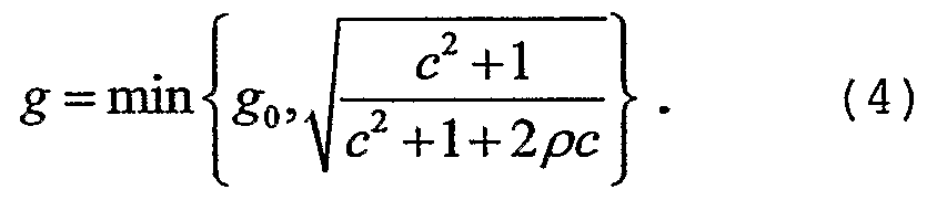
- the gain factor g can be expressed depending on the ICC and HD parameters and such the required limitation of the gain factor can be written as follows:
- the up mixing can be represented by a rotator matrix H as follows:
- the first column of the rotator matrix H is identical to the amplitude rotator used in parametric stereo, that is for example derived in WO 03/090206 Al.
- the downmix needs to be compatible with the up mix in the sense that perfect reconstruction is obtained when all lossy coding steps are omitted.
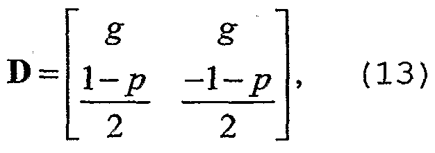
- the down- mixing matrix D the down- mixing matrix
- the problem analysis leading to the definition of the limiter 14 has been detailed. Although the notation is based on stereo signals, it is clear that the same method can be applied on any pair of audio signals, such as channel pairs selected from or generated by a partial downmix of a multi-channel audio signal . Particularly advantageous is, that the same limiting rule can be used to limit the parameters within the up-mixing and the down-mixing matrix.
- Fig. 2 describes the inventive audio encoding procedure using a block diagram, showing how the audio encoding is performed when following the inventive concept.
- the ICC and HD parameters are derived. These parameters are then forwarded as output 23 and transferred to serve as input for the limiting step 32, where a comparison of the ICC parameter with a computed minimal ICC parameter ICC mIn is made, wherein ICC m i n is depending on HD.
- the ICC parameter excedes the minimum ICC parameter ICC mIn (IID)
- the ICC parameter is directly forwarded to the down-mixing step 34.
- an additional exchange step 36 is performed, where the value of the ICC parameter is replaced by the value of the minimal ICC parameter ICC m I n (IID). After the exchange step 36, the ICC parameter having the new value is then transferred to the down-mixing step 34.
- the downmix signal 20 and the residual signal 22 are derived from the channels 1 and r, depending on the parameters ICC and HD.
- Fig. 3 shows another embodiment of an inventive audio encoding device 50 that comprises an audio encoder 10, a signal processing unit 51 having a first audio compressor 52, a second audio compressor 54, and a parameter compressor 56, and an output interface 58.
- the general purpose of the signal processing unit 51 is to compress the downmix signal 20, the residual signal 22 and the parameters 23. Therefore, the downmix signal 20 is input into the first audio compressor 52, the residual signal 22 is input into the second audio compressor 54 and the spatial parameters 23 are input into the parameter compressor 56.
- the first audio compressor 52 derives a first audio bit stream 60
- the second audio compressor 54 derives a second audio bit stream 62
- the parameter compressor 56 derives a parameter bit stream 64.
- the first and the second audio bit stream (60, 62) and the parameter bit stream 64 are then used as input of the output interface, that combines the three bit streams (60, 62, 64) to derive a combined bit stream 66, which is the output of the inventive encoding device 50.
- the combination performed by the output interface 58 could for example be a simple multiplexing of the three incoming bit streams. Furthermore, any kind of combination that leads to a single output bit stream 66 is possible. Dealing with a single bit stream is much more convenient in handling, such as streaming via the internet or other data links.
- Figure 3 illustrates an encoder that takes a two-channel audio signal, comprising the channels 1, r as input and generates a bitstream that permits decoding by a parametric stereo decoder.
- the adaptive downmix takes the two-channel signal 1, r and generates a mono downmix m and a residual signal s. These signals can then be encoded by perceptual audio encoders to produce compact audio bit- streams.
- the parametric stereo (PS) parameter estimation takes the two-channel signal 1, r as input and generates a set of PS parameters.
- the instability limiter modifies the PS parameters which control the adaptive downmix.
- the encoding block produces the parametric stereo side information (PS sideinfo) from the unmodified output of the PS parameter estimation.
- the multiplexer combines all encoded data to form the combined bitstream. It is one of the major advantages of the inventive coding concept, that it is fully backwards compatible to prior art parametric stereo decoders. To illustrate this, Fig. 4 shows a prior art parametric stereo decoder.
- the parametric stereo decoder 70 comprises an input interface 72, an audio decoder 74, a parameter decoder 76, and an up-mixer 78.
- the input interface 72 receives a combined bit stream 80 as produced from by inventive audio encoder 50.
- the input interface 72 of the prior art parametric stereo decoder 70 does not recognize the residual signal 22 and therefore only extracts the downmix signal 60 (first audio bit stream 60 from Fig. 3) and the parameter bit stream 64 from the input bit stream 80.
- the audio decoder 74 is the complementary device to the first audio compressor 52 and the parameter decoder 76 is the complementary device to the parameter compressor 56. Therefore, the audio bit stream 60 is decoded into the downmix signal 20 and the parameter bit stream 64 is decoded to the spatial parameters 23. Since the spatial parameters 23 have been directly transferred and not been further processed by the inventive encoder 10 or 50, a prior art up-mixer 78 can reconstruct a left and a right channel, building an output signal 80 from the down- mix signal 20 using the spatial parameters 23.
- Figure 4 illustrates a parametric stereo decoder that takes a compatible bitstream as generated by an inventive encoding device 50 as input and generates the stereo audio signal comprising the channels 1 and r, without using or without having access to the part of the bit- stream that describes the residual signal.
- a demultiplexer takes the compatible bitstream as input and decomposes it into one audio bitstreams and the PS sideinfo.
- the perceptual audio decoder produces a mono signal m, and the PS sideinfo is decoded into PS parameters.
- the PS synthesis converts the mono signal into left and right signals 1 and r in accordance with the PS-parameters, in particular by adding a decorrelated signal in order to retain the channel correlation of the original stereo channels
- Fig. 5 shows an inventive multi-channel-audio encoder 100 that encodes a 6-channel audio signal into a stereo downmix and a number of parameter sets.
- the multi-channel audio encoder 100 comprises a first adaptive encoder 102, a second adaptive encoder 104, estimation module 106, a parameter extractor 108, and a 3 to 2 down- mixer 110.
- the first adaptive encoder 102 and the second adaptive encoder 104 are embodiments of an inventive encoder 10.
- the 6 channel input signal is having a left front channel 112a, a left rear channel 112b, a right front channel 114a, a right rear channel 114b, a center channel 116a, and a low frequency enhancement channel 116b.
- the left front channel 112a and the left rear channel 112b are input into the first adaptive encoder 102 that derives a first downmix signal 118a, the corresponding residual signal 118b and spatial parameters 118c.
- the right front channel 114a and the right rear channel 114b are input into the second adaptive encoder 104, that derives a second downmix signal 120a, the corresponding residual signal 120b, and the underlying spatial parameters 120c.
- the center channel 116a and the low frequency enhancement channel 116b are input into the summation module 106, that adds the signals to create a mono signal 122a and corresponding spatial parameters 122b.
- the 3 to 2 down-mixer 110 receives the downmix signals 118a, 120a, and 122a to down-mix them into a stereo output signal 124 having a left and a right channel.
- the 3 to 2 down-mixer additionally derives a residual signal 126 from the input channels 118a, 120a, and 122a.
- the 3 to 2 down-mixer 110 derives a parameter set 128 from the parameter sets 118b, 120b, and 122b.
- Fig. 5 illustrates a part of a spatial audio encoder that takes as input a multi-channel audio signal in 5.1 format, comprising the channels Lf (left front) , Lr (left surround) , Rf (right front) , Rr (right surround) , C (centre) and LFE (low-frequency efficient) , and that creates a stereo down-mix, comprising LO and RO, and a number of parameter sets.
- a stereo down-mix comprising LO and RO
- Not shown in this figure are time to frequency transforms, coding of the down-mix signals and parameters, and multiplexing the coded information into a bit-stream which can be decoded by a corresponding spatial audio decoder.
- the adaptive down-mix takes as input the signals Lf and Lr and produces a mono signal L and a residual signal L.
- the parametric stereo (PS) parameter estimation takes the two-channel signal Lf and Lr as input and generates a set of PS parameters .
- the instability limiter modifies the PS parameters that control the adaptive down-mix.
- the adaptive down-mix takes as input the signals Rf and Rr and produces a mono signal R and a residual signal R.
- the parametric stereo (PS) parameter estimation takes the two-channel signal Rf and Rr as input and generates a set of PS parameters.
- the instability limiter modifies the PS parameters that control the adaptive down-mix.
- the summation module adds the signals C and LFE to create a mono signal C.
- the parametric stereo (PS) parameter estimation takes the two-channel signal C and LFE as input and generates a set of HD parameters, a subset of PS parameters.
- the mono signals L, R and C are mixed to a stereo signal (Lo and Ro) and a residual signal Eo by the 3 to 2 module.
- the 3 to 2 module also outputs a parameter set ⁇ Lo, Ro ⁇ .
- Fig. 6 describes an inventive audio decoder 140, comprising an up-mixer 142, and a limiter 144.
- the inventive decoder 140 receives a downmix signal 146, a residual signal 148 and spatial parameters 150.
- the downmix signal 146 and the residual signal 148 are input into the up-mixer 142, whereas the spatial parameters 150 are input into the limiter 144.
- the limiter 144 limits the spatial parameters 150 to derive limited spatial parameters 152.
- the limiter is using the same limiting rule to derive the limited parameters as the corresponding encoder during the encoding process .
- the limited parameters are used to control the up-mixing process in the up-mixer 142 that derives a stereo signal 154 having a left and a right channel from the downmix signal 146 and the residual signal 148.
- Fig. 7 shows a block diagram illustrating the principle of an inventive decoder.
- a first limiting step 160 the received spatial parameters ICC and HD are limited. That is, it is checked whether the received ICC parameter exceeds a minimum ICC parameter ICC mIn (HD). If this is the case, the spatial parameters 150 (ICC and HD) , a received downmix signal 146, and a received residual signal 148 are transmitted to the up-mixing step 162.
- a limiting step 164 is additionally performed, where the value of the ICC parameter is exchanged by the value of the parameter ICCn 1 I n (IID), having the effect, that the value of ICC 1O i n (IID) is transmitted to the up-mixing step 162.
- a stereo signal 154 having a left and a right channel is derived from the downmix signal 146 and the residual signal 148, using the spatial parameters ICC and HD.
- Fig. 8 shows a further embodiment of an inventive decoding device 180 that comprises a decoder 140, a signal- processing unit 182 having a first audio decoder 184, a second audio decoder 186 and a parameter decoder 188.
- the decoding device 180 further comprises an input interface 190 for receiving a combined bit stream 192, that is generated by an inventive encoding device 50.
- the combined bit stream 192 is decoposed by the input interface 190 to a first audio bit stream 194a, a second audio bit stream 194b and a parameter bit stream 196.
- the first audio bit stream 194a is input into the first audio decoder 185
- the second audio bit stream 194b is input into the second audio decoder 186
- the parameter bit stream 196 is input into the parameter decoder 188.
- the decompressed downmix signal 198 (m) and the residual signal 200 (s) are input into the up-mixer 142 of the decoder 140.
- Spatial parameters 202 derived by the parameter decoder 188 are input into the limiter 144 of the audio decoder 140.
- the limiting of the spatial parameters and the up-mixing have already been described within the description of the audio decoder 140. A detailed description can be obtained from the corresponding paragraphs of the description of Fig. 6.
- the inventive decoding device 180 finally outputs a stereo signal 204, having a left and a right channel.
- fig. 8 illustrates a parametric stereo decoder that takes a compatible bitstream as input and generates the stereo audio signal comprising the channels 1 and r.
- a demultiplexer takes the compatible bit stream as input and decomposes it into two audio bit streams and the PS side info.
- Perceptual audio decoders produce a mono signal m and a residual signal s respectively, and the PS side info is decoded into PS parameters by the parameter decoder.
- the instability limiter modifies the PS parameters.
- the up-mixer converts the mono and residual signals into left and right signals 1 and r by means of a rotation matrix defined from the PS parameters modified by the instability limiter.
- Fig. 9 shows an inventive multi-channel audio decoder 210 comprising a first two-channel decoder 212, a second two- channel decoder 214, a synthesis module 216, and a 2 to 3 module 218.
- Figure 9 illustrates part of a spatial audio decoder that takes as input a stereo audio signal (comprising the Lo and Ro) , a residual signal Eo and a parameter set ⁇ Lo, Ro ⁇ .
- the 2 to 3 module 218 produces three audio channels L, R, and C from the above-mentioned input.
- the mono channel L and the residual channel L are converted by a first two-channel decoder 211 into the Lf and Lr output signals .
- the instability limiter modifies the PS parameter set L.
- the mono channel R and the residual channel R are converted by a second two-channel decoder 214 into the Rf and Rr output signals.
- the instability limiter is the same as used during the generation of the mono channel R and modifies the PS parameter set R.
- the PS synthesis module 216 takes the mono channel C and parameter set C and generates the C and LFE output channels.
- Fig. 10 and 11 show an alternative solution for an encoder and a decoder avoiding the instability problem.
- the alternative is based on using the limited spatial parameters as the parameters to be encoded and transmitted. This can be seen in the inventive encoder in Fig. 10 that is based on the inventive encoding device of Fig. 3.
- Fig. 10 shows a modification of an inventive encoder already shown in Fig. 3, with the difference, that the parameters fed into the parameter encoder 56 are taken at a point 300, i.e. after the limiting process. That is, the limited parameters are encoded and transmitted instead of the original parameters .
- Fig. 12 is showing an inventive audio transmitter or recorder 330 that is having an audio encoder 50, an input interface 332 and an output interface 334.
- An audio signal can be supplied at the input interface 332 of the transmitter/recorder 330.
- the audio signal is encoded by an inventive encoder 50 within the transmitter/recorder and the encoded representation is output at the output interface 334 of the transmitter/recorder 330.
- the encoded representation may then be transmitted or stored on a storage medium.
- Fig. 13 shows an inventive receiver or audio player 340, having an inventive audio decoder 180, a bit stream input 342, and an audio output 344.
- a bit stream can be input at the input 342 of the inventive receiver/audio player 340.
- the bit stream then is decoded by the decoder 180 and the decoded signal is output or played at the output 344 of the inventive receiver/audio player 340.
- Fig. 14 shows a transmission system comprising an inventive transmitter 330, and an inventive receiver 340.
- the audio signal input at the input interface 332 of the transmitter 330 is encoded and transferred from the output 334 of the transmitter 330 to the input 342 of the receiver 340.
- the receiver decodes the audio signal and plays back or outputs the audio signal on its output 344.
- the transmission between the transmitter and the receiver can be achieved by various means.
- This can be for example life streaming over the internet or other network media, storing a file on a computer readable media and transferring the media, directly connecting the transmitter and the receiver by cable or wireless such as wire- less LAN or Bluetooth and any other imaginable data connection.
- the ICC parameter only is to be changed to assure a non-diverging up- and downmix matrix
- applying the inventive concept can also mean deriving other spatial parameters and applying a limiting rule to these parameters, assuring for a non- diverging down- and up-mix.
- the output and input interfaces in the inventive encoders and decoders are not limited to simple multiplexers or demultiplexers only.
- the output interface may combine the bit streams not by just multiplexing them but by any other means, possibly even by trying some further entropy coding to reduce the size of the bit stream.
- the inventive methods can be implemented in hardware or in software.
- the implementation can be performed using a digital storage medium, in particular a disk, DVD or a CD having electronically readable control signals stored thereon, which cooperate with a programmable computer system such that the inventive methods are performed.
- the present invention is, therefore, a computer program product with a program code stored on a machine-readable carrier, the program code being operative for performing the inventive methods when the computer program product runs on a computer.
- the inventive methods are, therefore, a computer program having a program code for performing at least one of the inventive methods when the computer program runs on a computer.
Landscapes
- Engineering & Computer Science (AREA)
- Physics & Mathematics (AREA)
- Audiology, Speech & Language Pathology (AREA)
- Computational Linguistics (AREA)
- Signal Processing (AREA)
- Health & Medical Sciences (AREA)
- Mathematical Physics (AREA)
- Human Computer Interaction (AREA)
- Acoustics & Sound (AREA)
- Multimedia (AREA)
- Stereophonic System (AREA)
- Compression, Expansion, Code Conversion, And Decoders (AREA)
- Transmission Systems Not Characterized By The Medium Used For Transmission (AREA)
Abstract
Description


Claims


Priority Applications (9)
| Application Number | Priority Date | Filing Date | Title |
|---|---|---|---|
| BRPI0612218-3A BRPI0612218B1 (en) | 2005-04-15 | 2006-04-07 | adaptive residual audio coding |
| DE602006011591T DE602006011591D1 (en) | 2005-04-15 | 2006-04-07 | ADAPTIVE RESTSIGNAL AUDIO CODING |
| CN2006800121211A CN101160619B (en) | 2005-04-15 | 2006-04-07 | Adaptive residual audio coding |
| MX2007012686A MX2007012686A (en) | 2005-04-15 | 2006-04-07 | Adaptive residual audio coding. |
| PL06742550T PL1869668T3 (en) | 2005-04-15 | 2006-04-07 | Adaptive residual audio coding |
| AT06742550T ATE454693T1 (en) | 2005-04-15 | 2006-04-07 | ADAPTIVE RESIDUAL AUDIO CODING |
| JP2008505784A JP4685925B2 (en) | 2005-04-15 | 2006-04-07 | Adaptive residual audio coding |
| EP06742550A EP1869668B1 (en) | 2005-04-15 | 2006-04-07 | Adaptive residual audio coding |
| HK08104988.8A HK1110985A1 (en) | 2005-04-15 | 2008-05-05 | Adaptive residual audio coding |
Applications Claiming Priority (4)
| Application Number | Priority Date | Filing Date | Title |
|---|---|---|---|
| US67158105P | 2005-04-15 | 2005-04-15 | |
| US60/671,581 | 2005-04-15 | ||
| US11/247,555 US7751572B2 (en) | 2005-04-15 | 2005-10-11 | Adaptive residual audio coding |
| US11/247,555 | 2005-10-11 |
Publications (1)
| Publication Number | Publication Date |
|---|---|
| WO2006108573A1 true WO2006108573A1 (en) | 2006-10-19 |
Family
ID=36589009
Family Applications (1)
| Application Number | Title | Priority Date | Filing Date |
|---|---|---|---|
| PCT/EP2006/003200 WO2006108573A1 (en) | 2005-04-15 | 2006-04-07 | Adaptive residual audio coding |
Country Status (16)
| Country | Link |
|---|---|
| US (1) | US7751572B2 (en) |
| EP (1) | EP1869668B1 (en) |
| JP (1) | JP4685925B2 (en) |
| KR (1) | KR100955361B1 (en) |
| CN (1) | CN101160619B (en) |
| AT (1) | ATE454693T1 (en) |
| BR (1) | BRPI0612218B1 (en) |
| DE (1) | DE602006011591D1 (en) |
| ES (1) | ES2338918T3 (en) |
| HK (1) | HK1110985A1 (en) |
| MX (1) | MX2007012686A (en) |
| MY (1) | MY147609A (en) |
| PL (1) | PL1869668T3 (en) |
| RU (1) | RU2380766C2 (en) |
| TW (1) | TWI303411B (en) |
| WO (1) | WO2006108573A1 (en) |
Cited By (14)
| Publication number | Priority date | Publication date | Assignee | Title |
|---|---|---|---|---|
| WO2008078973A1 (en) * | 2006-12-27 | 2008-07-03 | Electronics And Telecommunications Research Institute | Apparatus and method for coding and decoding multi-object audio signal with various channel including information bitstream conversion |
| WO2010042024A1 (en) * | 2008-10-10 | 2010-04-15 | Telefonaktiebolaget Lm Ericsson (Publ) | Energy conservative multi-channel audio coding |
| CN101911733A (en) * | 2008-01-01 | 2010-12-08 | Lg电子株式会社 | The method and apparatus that is used for audio signal |
| EP2261894A1 (en) * | 2008-03-14 | 2010-12-15 | NEC Corporation | Signal analysis/control system and method, signal control device and method, and program |
| JP2011501544A (en) * | 2007-10-17 | 2011-01-06 | フラウンホッファー−ゲゼルシャフト ツァ フェルダールング デァ アンゲヴァンテン フォアシュンク エー.ファオ | Audio coding with downmix |
| JP2011509590A (en) * | 2008-01-01 | 2011-03-24 | エルジー エレクトロニクス インコーポレイティド | Audio signal processing method and apparatus |
| JP2011527763A (en) * | 2008-07-11 | 2011-11-04 | サムスン エレクトロニクス カンパニー リミテッド | Multi-channel encoding and decoding method and apparatus |
| KR101356972B1 (en) | 2009-04-08 | 2014-02-05 | 프라운호퍼 게젤샤프트 쭈르 푀르데룽 데어 안겐반텐 포르슝 에. 베. | Apparatus, method and computer program for upmixing a downmix audio signal using a phase value smoothing |
| US8781133B2 (en) | 2008-12-11 | 2014-07-15 | Fraunhofer-Gesellschaft Zur Foerderung Der Angewandten Forschung E.V. | Apparatus for generating a multi-channel audio signal |
| US8818764B2 (en) | 2010-03-30 | 2014-08-26 | Fujitsu Limited | Downmixing device and method |
| US9591425B2 (en) | 2008-05-23 | 2017-03-07 | Koninklijke Philips N.V. | Parametric stereo upmix apparatus, a parametric stereo decoder, a parametric stereo downmix apparatus, a parametric stereo encoder |
| WO2017049396A1 (en) | 2015-09-25 | 2017-03-30 | Voiceage Corporation | Method and system for time domain down mixing a stereo sound signal into primary and secondary channels using detecting an out-of-phase condition of the left and right channels |
| EP3550561A1 (en) * | 2018-04-06 | 2019-10-09 | Fraunhofer-Gesellschaft zur Förderung der angewandten Forschung e.V. | Downmixer, audio encoder, method and computer program applying a phase value to a magnitude value |
| RU2773510C2 (en) * | 2018-04-06 | 2022-06-06 | Фраунхофер-Гезелльшафт Цур Фердерунг Дер Ангевандтен Форшунг Е.Ф. | Downmixer, audio encoder, method and computer program applying phase value to absolute value |
Families Citing this family (90)
| Publication number | Priority date | Publication date | Assignee | Title |
|---|---|---|---|---|
| US8150042B2 (en) * | 2004-07-14 | 2012-04-03 | Koninklijke Philips Electronics N.V. | Method, device, encoder apparatus, decoder apparatus and audio system |
| DE102004043521A1 (en) * | 2004-09-08 | 2006-03-23 | Fraunhofer-Gesellschaft zur Förderung der angewandten Forschung e.V. | Device and method for generating a multi-channel signal or a parameter data set |
| ES2623551T3 (en) * | 2005-03-25 | 2017-07-11 | Iii Holdings 12, Llc | Sound coding device and sound coding procedure |
| WO2006126843A2 (en) * | 2005-05-26 | 2006-11-30 | Lg Electronics Inc. | Method and apparatus for decoding audio signal |
| JP4988717B2 (en) * | 2005-05-26 | 2012-08-01 | エルジー エレクトロニクス インコーポレイティド | Audio signal decoding method and apparatus |
| US8270439B2 (en) * | 2005-07-08 | 2012-09-18 | Activevideo Networks, Inc. | Video game system using pre-encoded digital audio mixing |
| US20070055510A1 (en) * | 2005-07-19 | 2007-03-08 | Johannes Hilpert | Concept for bridging the gap between parametric multi-channel audio coding and matrixed-surround multi-channel coding |
| US8074248B2 (en) | 2005-07-26 | 2011-12-06 | Activevideo Networks, Inc. | System and method for providing video content associated with a source image to a television in a communication network |
| KR101228630B1 (en) * | 2005-09-02 | 2013-01-31 | 파나소닉 주식회사 | Energy shaping device and energy shaping method |
| US20080221907A1 (en) * | 2005-09-14 | 2008-09-11 | Lg Electronics, Inc. | Method and Apparatus for Decoding an Audio Signal |
| KR100857108B1 (en) * | 2005-09-14 | 2008-09-05 | 엘지전자 주식회사 | Method and apparatus for decoding an audio signal |
| US20080255859A1 (en) * | 2005-10-20 | 2008-10-16 | Lg Electronics, Inc. | Method for Encoding and Decoding Multi-Channel Audio Signal and Apparatus Thereof |
| US8208641B2 (en) * | 2006-01-19 | 2012-06-26 | Lg Electronics Inc. | Method and apparatus for processing a media signal |
| US8285556B2 (en) * | 2006-02-07 | 2012-10-09 | Lg Electronics Inc. | Apparatus and method for encoding/decoding signal |
| CN101401152B (en) * | 2006-03-15 | 2012-04-18 | 法国电信公司 | Device and method for encoding by principal component analysis a multichannel audio signal |
| FR2898725A1 (en) * | 2006-03-15 | 2007-09-21 | France Telecom | DEVICE AND METHOD FOR GRADUALLY ENCODING A MULTI-CHANNEL AUDIO SIGNAL ACCORDING TO MAIN COMPONENT ANALYSIS |
| US8027479B2 (en) * | 2006-06-02 | 2011-09-27 | Coding Technologies Ab | Binaural multi-channel decoder in the context of non-energy conserving upmix rules |
| US20080235006A1 (en) * | 2006-08-18 | 2008-09-25 | Lg Electronics, Inc. | Method and Apparatus for Decoding an Audio Signal |
| KR101434198B1 (en) * | 2006-11-17 | 2014-08-26 | 삼성전자주식회사 | Method of decoding a signal |
| US9042454B2 (en) | 2007-01-12 | 2015-05-26 | Activevideo Networks, Inc. | Interactive encoded content system including object models for viewing on a remote device |
| US9826197B2 (en) | 2007-01-12 | 2017-11-21 | Activevideo Networks, Inc. | Providing television broadcasts over a managed network and interactive content over an unmanaged network to a client device |
| US8639498B2 (en) * | 2007-03-30 | 2014-01-28 | Electronics And Telecommunications Research Institute | Apparatus and method for coding and decoding multi object audio signal with multi channel |
| US9653088B2 (en) | 2007-06-13 | 2017-05-16 | Qualcomm Incorporated | Systems, methods, and apparatus for signal encoding using pitch-regularizing and non-pitch-regularizing coding |
| WO2009050896A1 (en) * | 2007-10-16 | 2009-04-23 | Panasonic Corporation | Stream generating device, decoding device, and method |
| KR101505831B1 (en) * | 2007-10-30 | 2015-03-26 | 삼성전자주식회사 | Method and Apparatus of Encoding/Decoding Multi-Channel Signal |
| KR101597375B1 (en) | 2007-12-21 | 2016-02-24 | 디티에스 엘엘씨 | System for adjusting perceived loudness of audio signals |
| WO2009096898A1 (en) * | 2008-01-31 | 2009-08-06 | Agency For Science, Technology And Research | Method and device of bitrate distribution/truncation for scalable audio coding |
| JP5383676B2 (en) * | 2008-05-30 | 2014-01-08 | パナソニック株式会社 | Encoding device, decoding device and methods thereof |
| WO2009153995A1 (en) * | 2008-06-19 | 2009-12-23 | パナソニック株式会社 | Quantizer, encoder, and the methods thereof |
| US20110112843A1 (en) * | 2008-07-11 | 2011-05-12 | Nec Corporation | Signal analyzing device, signal control device, and method and program therefor |
| KR101614160B1 (en) * | 2008-07-16 | 2016-04-20 | 한국전자통신연구원 | Apparatus for encoding and decoding multi-object audio supporting post downmix signal |
| FR2936898A1 (en) * | 2008-10-08 | 2010-04-09 | France Telecom | CRITICAL SAMPLING CODING WITH PREDICTIVE ENCODER |
| EP2396637A1 (en) * | 2009-02-13 | 2011-12-21 | Nokia Corp. | Ambience coding and decoding for audio applications |
| JP5564803B2 (en) * | 2009-03-06 | 2014-08-06 | ソニー株式会社 | Acoustic device and acoustic processing method |
| MX2011009660A (en) | 2009-03-17 | 2011-09-30 | Dolby Int Ab | Advanced stereo coding based on a combination of adaptively selectable left/right or mid/side stereo coding and of parametric stereo coding. |
| KR101387808B1 (en) * | 2009-04-15 | 2014-04-21 | 한국전자통신연구원 | Apparatus for high quality multiple audio object coding and decoding using residual coding with variable bitrate |
| CN102414990A (en) * | 2009-05-29 | 2012-04-11 | 日本电信电话株式会社 | Coding device, decoding device, coding method, decoding method, and program therefor |
| WO2011013381A1 (en) * | 2009-07-31 | 2011-02-03 | パナソニック株式会社 | Coding device and decoding device |
| US8194862B2 (en) * | 2009-07-31 | 2012-06-05 | Activevideo Networks, Inc. | Video game system with mixing of independent pre-encoded digital audio bitstreams |
| US8538042B2 (en) | 2009-08-11 | 2013-09-17 | Dts Llc | System for increasing perceived loudness of speakers |
| KR20110018107A (en) * | 2009-08-17 | 2011-02-23 | 삼성전자주식회사 | Residual signal encoding and decoding method and apparatus |
| KR101613975B1 (en) * | 2009-08-18 | 2016-05-02 | 삼성전자주식회사 | Method and apparatus for encoding multi-channel audio signal, and method and apparatus for decoding multi-channel audio signal |
| TWI433137B (en) | 2009-09-10 | 2014-04-01 | Dolby Int Ab | Improvement of an audio signal of an fm stereo radio receiver by using parametric stereo |
| WO2011029984A1 (en) * | 2009-09-11 | 2011-03-17 | Nokia Corporation | Method, apparatus and computer program product for audio coding |
| KR101710113B1 (en) * | 2009-10-23 | 2017-02-27 | 삼성전자주식회사 | Apparatus and method for encoding/decoding using phase information and residual signal |
| EP2346028A1 (en) | 2009-12-17 | 2011-07-20 | Fraunhofer-Gesellschaft zur Förderung der Angewandten Forschung e.V. | An apparatus and a method for converting a first parametric spatial audio signal into a second parametric spatial audio signal |
| CN102792378B (en) * | 2010-01-06 | 2015-04-29 | Lg电子株式会社 | An apparatus for processing an audio signal and method thereof |
| CN102884570B (en) * | 2010-04-09 | 2015-06-17 | 杜比国际公司 | MDCT-based complex prediction stereo coding |
| EP2375409A1 (en) * | 2010-04-09 | 2011-10-12 | Fraunhofer-Gesellschaft zur Förderung der angewandten Forschung e.V. | Audio encoder, audio decoder and related methods for processing multi-channel audio signals using complex prediction |
| JP5581449B2 (en) * | 2010-08-24 | 2014-08-27 | ドルビー・インターナショナル・アーベー | Concealment of intermittent mono reception of FM stereo radio receiver |
| US8885701B2 (en) * | 2010-09-08 | 2014-11-11 | Samsung Electronics Co., Ltd. | Low complexity transform coding using adaptive DCT/DST for intra-prediction |
| JP5533502B2 (en) * | 2010-09-28 | 2014-06-25 | 富士通株式会社 | Audio encoding apparatus, audio encoding method, and audio encoding computer program |
| AU2011315950B2 (en) | 2010-10-14 | 2015-09-03 | Activevideo Networks, Inc. | Streaming digital video between video devices using a cable television system |
| FR2966634A1 (en) * | 2010-10-22 | 2012-04-27 | France Telecom | ENHANCED STEREO PARAMETRIC ENCODING / DECODING FOR PHASE OPPOSITION CHANNELS |
| TWI462087B (en) | 2010-11-12 | 2014-11-21 | Dolby Lab Licensing Corp | Downmix limiting |
| CN102056053B (en) * | 2010-12-17 | 2015-04-01 | 中兴通讯股份有限公司 | Multi-microphone audio mixing method and device |
| WO2012138660A2 (en) | 2011-04-07 | 2012-10-11 | Activevideo Networks, Inc. | Reduction of latency in video distribution networks using adaptive bit rates |
| UA107771C2 (en) * | 2011-09-29 | 2015-02-10 | Dolby Int Ab | Prediction-based fm stereo radio noise reduction |
| US10409445B2 (en) | 2012-01-09 | 2019-09-10 | Activevideo Networks, Inc. | Rendering of an interactive lean-backward user interface on a television |
| US9800945B2 (en) | 2012-04-03 | 2017-10-24 | Activevideo Networks, Inc. | Class-based intelligent multiplexing over unmanaged networks |
| US9312829B2 (en) | 2012-04-12 | 2016-04-12 | Dts Llc | System for adjusting loudness of audio signals in real time |
| US9123084B2 (en) | 2012-04-12 | 2015-09-01 | Activevideo Networks, Inc. | Graphical application integration with MPEG objects |
| KR20140017338A (en) * | 2012-07-31 | 2014-02-11 | 인텔렉추얼디스커버리 주식회사 | Apparatus and method for audio signal processing |
| MY176406A (en) * | 2012-08-10 | 2020-08-06 | Fraunhofer Ges Forschung | Encoder, decoder, system and method employing a residual concept for parametric audio object coding |
| CN103067629B (en) * | 2013-01-18 | 2014-10-29 | 苏州科达科技股份有限公司 | echo cancellation device |
| EP2757558A1 (en) | 2013-01-18 | 2014-07-23 | Fraunhofer-Gesellschaft zur Förderung der angewandten Forschung e.V. | Time domain level adjustment for audio signal decoding or encoding |
| RU2676870C1 (en) * | 2013-01-29 | 2019-01-11 | Фраунхофер-Гезелльшафт Цур Фердерунг Дер Ангевандтен Форшунг Е.Ф. | Decoder for formation of audio signal with improved frequency characteristic, decoding method, encoder for formation of encoded signal and encoding method using compact additional information for selection |
| WO2014145921A1 (en) | 2013-03-15 | 2014-09-18 | Activevideo Networks, Inc. | A multiple-mode system and method for providing user selectable video content |
| KR20140123015A (en) * | 2013-04-10 | 2014-10-21 | 한국전자통신연구원 | Encoder and encoding method for multi-channel signal, and decoder and decoding method for multi-channel signal |
| CN110223702B (en) | 2013-05-24 | 2023-04-11 | 杜比国际公司 | Audio decoding system and reconstruction method |
| US9294785B2 (en) | 2013-06-06 | 2016-03-22 | Activevideo Networks, Inc. | System and method for exploiting scene graph information in construction of an encoded video sequence |
| US9219922B2 (en) | 2013-06-06 | 2015-12-22 | Activevideo Networks, Inc. | System and method for exploiting scene graph information in construction of an encoded video sequence |
| EP3005712A1 (en) | 2013-06-06 | 2016-04-13 | ActiveVideo Networks, Inc. | Overlay rendering of user interface onto source video |
| KR20150009474A (en) * | 2013-07-15 | 2015-01-26 | 한국전자통신연구원 | Encoder and encoding method for multi-channel signal, and decoder and decoding method for multi-channel signal |
| EP2830052A1 (en) | 2013-07-22 | 2015-01-28 | Fraunhofer-Gesellschaft zur Förderung der angewandten Forschung e.V. | Audio decoder, audio encoder, method for providing at least four audio channel signals on the basis of an encoded representation, method for providing an encoded representation on the basis of at least four audio channel signals and computer program using a bandwidth extension |
| EP2830053A1 (en) * | 2013-07-22 | 2015-01-28 | Fraunhofer-Gesellschaft zur Förderung der angewandten Forschung e.V. | Multi-channel audio decoder, multi-channel audio encoder, methods and computer program using a residual-signal-based adjustment of a contribution of a decorrelated signal |
| TWI579831B (en) | 2013-09-12 | 2017-04-21 | 杜比國際公司 | Method for quantization of parameters, method for dequantization of quantized parameters and computer-readable medium, audio encoder, audio decoder and audio system thereof |
| CN105531761B (en) | 2013-09-12 | 2019-04-30 | 杜比国际公司 | Audio decoding system and audio coding system |
| US9788029B2 (en) | 2014-04-25 | 2017-10-10 | Activevideo Networks, Inc. | Intelligent multiplexing using class-based, multi-dimensioned decision logic for managed networks |
| CN105989851B (en) | 2015-02-15 | 2021-05-07 | 杜比实验室特许公司 | Audio source separation |
| US9978381B2 (en) * | 2016-02-12 | 2018-05-22 | Qualcomm Incorporated | Encoding of multiple audio signals |
| CN109644315A (en) * | 2017-02-17 | 2019-04-16 | 无比的优声音科技公司 | Device and method for the mixed multi-channel audio signal that contracts |
| WO2019076739A1 (en) * | 2017-10-16 | 2019-04-25 | Sony Europe Limited | Audio processing |
| CN110556119B (en) | 2018-05-31 | 2022-02-18 | 华为技术有限公司 | Method and device for calculating downmix signal |
| CN110556116B (en) | 2018-05-31 | 2021-10-22 | 华为技术有限公司 | Method and apparatus for calculating downmix signal and residual signal |
| CN114708874A (en) | 2018-05-31 | 2022-07-05 | 华为技术有限公司 | Coding method and device for stereo signal |
| RU2769429C2 (en) * | 2018-08-17 | 2022-03-31 | Нокиа Текнолоджиз Ой | Audio signal encoder |
| GB2578625A (en) * | 2018-11-01 | 2020-05-20 | Nokia Technologies Oy | Apparatus, methods and computer programs for encoding spatial metadata |
| GB2582749A (en) * | 2019-03-28 | 2020-10-07 | Nokia Technologies Oy | Determination of the significance of spatial audio parameters and associated encoding |
| WO2020216459A1 (en) * | 2019-04-23 | 2020-10-29 | Fraunhofer-Gesellschaft zur Förderung der angewandten Forschung e.V. | Apparatus, method or computer program for generating an output downmix representation |
Citations (1)
| Publication number | Priority date | Publication date | Assignee | Title |
|---|---|---|---|---|
| US6021386A (en) * | 1991-01-08 | 2000-02-01 | Dolby Laboratories Licensing Corporation | Coding method and apparatus for multiple channels of audio information representing three-dimensional sound fields |
Family Cites Families (18)
| Publication number | Priority date | Publication date | Assignee | Title |
|---|---|---|---|---|
| DE4236989C2 (en) | 1992-11-02 | 1994-11-17 | Fraunhofer Ges Forschung | Method for transmitting and / or storing digital signals of multiple channels |
| US5960390A (en) * | 1995-10-05 | 1999-09-28 | Sony Corporation | Coding method for using multi channel audio signals |
| US6036878A (en) * | 1996-02-02 | 2000-03-14 | Applied Materials, Inc. | Low density high frequency process for a parallel-plate electrode plasma reactor having an inductive antenna |
| SG54379A1 (en) | 1996-10-24 | 1998-11-16 | Sgs Thomson Microelectronics A | Audio decoder with an adaptive frequency domain downmixer |
| JP4610087B2 (en) | 1999-04-07 | 2011-01-12 | ドルビー・ラボラトリーズ・ライセンシング・コーポレーション | Matrix improvement to lossless encoding / decoding |
| US6363338B1 (en) * | 1999-04-12 | 2002-03-26 | Dolby Laboratories Licensing Corporation | Quantization in perceptual audio coders with compensation for synthesis filter noise spreading |
| JP2002076904A (en) | 2000-09-04 | 2002-03-15 | Victor Co Of Japan Ltd | Method of decoding coded audio signal, and decoder therefor |
| US7120587B2 (en) | 2000-11-03 | 2006-10-10 | Koninklijke Philips Electronics N.V. | Sinusoidal model based coding of audio signals |
| JP2002175097A (en) | 2000-12-06 | 2002-06-21 | Yamaha Corp | Encoding and compressing device, and decoding and expanding device for voice signal |
| JP3951690B2 (en) | 2000-12-14 | 2007-08-01 | ソニー株式会社 | Encoding apparatus and method, and recording medium |
| US7292901B2 (en) | 2002-06-24 | 2007-11-06 | Agere Systems Inc. | Hybrid multi-channel/cue coding/decoding of audio signals |
| KR20040080003A (en) | 2002-02-18 | 2004-09-16 | 코닌클리케 필립스 일렉트로닉스 엔.브이. | Parametric audio coding |
| ATE459957T1 (en) | 2002-04-10 | 2010-03-15 | Koninkl Philips Electronics Nv | CODING AND DECODING FOR MULTI-CHANNEL SIGNALS |
| CN100508026C (en) | 2002-04-10 | 2009-07-01 | 皇家飞利浦电子股份有限公司 | Coding of stereo signals |
| EP1500084B1 (en) | 2002-04-22 | 2008-01-23 | Koninklijke Philips Electronics N.V. | Parametric representation of spatial audio |
| JP2003330497A (en) | 2002-05-15 | 2003-11-19 | Matsushita Electric Ind Co Ltd | Method and device for encoding audio signal, encoding and decoding system, program for executing encoding, and recording medium with the program recorded thereon |
| CN1231889C (en) * | 2002-11-19 | 2005-12-14 | 华为技术有限公司 | Speech processing method of multi-channel vocoder |
| US7573912B2 (en) * | 2005-02-22 | 2009-08-11 | Fraunhofer-Gesellschaft Zur Foerderung Der Angewandten Forschunng E.V. | Near-transparent or transparent multi-channel encoder/decoder scheme |
-
2005
- 2005-10-11 US US11/247,555 patent/US7751572B2/en active Active
-
2006
- 2006-04-07 PL PL06742550T patent/PL1869668T3/en unknown
- 2006-04-07 AT AT06742550T patent/ATE454693T1/en not_active IP Right Cessation
- 2006-04-07 MX MX2007012686A patent/MX2007012686A/en active IP Right Grant
- 2006-04-07 JP JP2008505784A patent/JP4685925B2/en active Active
- 2006-04-07 WO PCT/EP2006/003200 patent/WO2006108573A1/en active Application Filing
- 2006-04-07 BR BRPI0612218-3A patent/BRPI0612218B1/en active IP Right Grant
- 2006-04-07 DE DE602006011591T patent/DE602006011591D1/en active Active
- 2006-04-07 EP EP06742550A patent/EP1869668B1/en active Active
- 2006-04-07 KR KR1020077023341A patent/KR100955361B1/en active IP Right Grant
- 2006-04-07 ES ES06742550T patent/ES2338918T3/en active Active
- 2006-04-07 CN CN2006800121211A patent/CN101160619B/en active Active
- 2006-04-07 RU RU2007142177/09A patent/RU2380766C2/en active
- 2006-04-12 TW TW095113074A patent/TWI303411B/en active
- 2006-04-12 MY MYPI20061673A patent/MY147609A/en unknown
-
2008
- 2008-05-05 HK HK08104988.8A patent/HK1110985A1/en unknown
Patent Citations (1)
| Publication number | Priority date | Publication date | Assignee | Title |
|---|---|---|---|---|
| US6021386A (en) * | 1991-01-08 | 2000-02-01 | Dolby Laboratories Licensing Corporation | Coding method and apparatus for multiple channels of audio information representing three-dimensional sound fields |
Non-Patent Citations (3)
| Title |
|---|
| "Universal Mobile Telecommunications System (UMTS); General audio codec audio processing functions; Enhanced aacPlus general audio codec; Encoder specification; Parametric stereo part (3GPP TS 26.405 version 6.1.0 Release 6); ETSI TS 126 405", ETSI STANDARDS, EUROPEAN TELECOMMUNICATIONS STANDARDS INSTITUTE, SOPHIA-ANTIPO, FR, vol. 3-SA4, no. V610, March 2005 (2005-03-01), XP014027783, ISSN: 0000-0001 * |
| FALLER CHRISTOF: "Parametric coding of spatial audio - Thesis No 3062", THESE PRESENTEE A LA FACULTE INFORMATIQUE ET COMMUNICATIONS INSTITUT DE SYSTEMES DE COMMUNICATION SECTION DES SYSTEMES DE COMMUNICATION ÉCOLE POLYTECHNIQUE FÉDÉRALE DE LAUSANNE POUR L'OBTENTION DU GRADE DE DOCTEUR ES SCIENCES, XX, XX, 2004, pages complete, XP002343263 * |
| WERNER OOMEN, ERIK SCHUIJERS, HEIKO PURNHAGEN, JONAS ENGDEGARD: "MPEG4-EXT2: CE ON LOW COMPLEXITY PARAMETRIC STEREO - ISO/IEC JTC1/SC29/WG11 - MPEG2003/M10366", CODING OF MOVING PICTURES AND AUDIO - ISO/IEC, December 2003 (2003-12-01), Hawaii, XP002388137 * |
Cited By (53)
| Publication number | Priority date | Publication date | Assignee | Title |
|---|---|---|---|---|
| WO2008078973A1 (en) * | 2006-12-27 | 2008-07-03 | Electronics And Telecommunications Research Institute | Apparatus and method for coding and decoding multi-object audio signal with various channel including information bitstream conversion |
| CN103137132B (en) * | 2006-12-27 | 2016-09-07 | 韩国电子通信研究院 | Equipment for coding multi-object audio signal |
| US9257127B2 (en) | 2006-12-27 | 2016-02-09 | Electronics And Telecommunications Research Institute | Apparatus and method for coding and decoding multi-object audio signal with various channel including information bitstream conversion |
| CN103137132A (en) * | 2006-12-27 | 2013-06-05 | 韩国电子通信研究院 | Apparatus for coding multi-object audio signal |
| US8370164B2 (en) | 2006-12-27 | 2013-02-05 | Electronics And Telecommunications Research Institute | Apparatus and method for coding and decoding multi-object audio signal with various channel including information bitstream conversion |
| CN102883257A (en) * | 2006-12-27 | 2013-01-16 | 韩国电子通信研究院 | Apparatus and method for coding and decoding multi-object audio signal with various channel including information bitstream conversion |
| US8280744B2 (en) | 2007-10-17 | 2012-10-02 | Fraunhofer-Gesellschaft Zur Foerderung Der Angewandten Forschung E.V. | Audio decoder, audio object encoder, method for decoding a multi-audio-object signal, multi-audio-object encoding method, and non-transitory computer-readable medium therefor |
| JP2011501544A (en) * | 2007-10-17 | 2011-01-06 | フラウンホッファー−ゲゼルシャフト ツァ フェルダールング デァ アンゲヴァンテン フォアシュンク エー.ファオ | Audio coding with downmix |
| KR101303441B1 (en) | 2007-10-17 | 2013-09-10 | 프라운호퍼 게젤샤프트 쭈르 푀르데룽 데어 안겐반텐 포르슝 에. 베. | Audio coding using downmix |
| KR101290394B1 (en) | 2007-10-17 | 2013-07-26 | 프라운호퍼 게젤샤프트 쭈르 푀르데룽 데어 안겐반텐 포르슝 에. 베. | Audio coding using downmix |
| US9514758B2 (en) | 2008-01-01 | 2016-12-06 | Lg Electronics Inc. | Method and an apparatus for processing an audio signal |
| US8670576B2 (en) | 2008-01-01 | 2014-03-11 | Lg Electronics Inc. | Method and an apparatus for processing an audio signal |
| CN101911733A (en) * | 2008-01-01 | 2010-12-08 | Lg电子株式会社 | The method and apparatus that is used for audio signal |
| JP2011509588A (en) * | 2008-01-01 | 2011-03-24 | エルジー エレクトロニクス インコーポレイティド | Audio signal processing method and apparatus |
| JP2011509591A (en) * | 2008-01-01 | 2011-03-24 | エルジー エレクトロニクス インコーポレイティド | Audio signal processing method and apparatus |
| JP2011509589A (en) * | 2008-01-01 | 2011-03-24 | エルジー エレクトロニクス インコーポレイティド | Processing method and apparatus for audio signal |
| JP2011509590A (en) * | 2008-01-01 | 2011-03-24 | エルジー エレクトロニクス インコーポレイティド | Audio signal processing method and apparatus |
| US8654994B2 (en) | 2008-01-01 | 2014-02-18 | Lg Electronics Inc. | Method and an apparatus for processing an audio signal |
| US8665914B2 (en) | 2008-03-14 | 2014-03-04 | Nec Corporation | Signal analysis/control system and method, signal control apparatus and method, and program |
| EP2261894A4 (en) * | 2008-03-14 | 2013-01-16 | Nec Corp | Signal analysis/control system and method, signal control device and method, and program |
| EP2261894A1 (en) * | 2008-03-14 | 2010-12-15 | NEC Corporation | Signal analysis/control system and method, signal control device and method, and program |
| US11871205B2 (en) | 2008-05-23 | 2024-01-09 | Koninklijke Philips N.V. | Parametric stereo upmix apparatus, a parametric stereo decoder, a parametric stereo downmix apparatus, a parametric stereo encoder |
| US11019445B2 (en) | 2008-05-23 | 2021-05-25 | Koninklijke Philips N.V. | Parametric stereo upmix apparatus, a parametric stereo decoder, a parametric stereo downmix apparatus, a parametric stereo encoder |
| US10136237B2 (en) | 2008-05-23 | 2018-11-20 | Koninklijke Philips N.V. | Parametric stereo upmix apparatus, a parametric stereo decoder, a parametric stereo downmix apparatus, a parametric stereo encoder |
| US9591425B2 (en) | 2008-05-23 | 2017-03-07 | Koninklijke Philips N.V. | Parametric stereo upmix apparatus, a parametric stereo decoder, a parametric stereo downmix apparatus, a parametric stereo encoder |
| JP2014063202A (en) * | 2008-07-11 | 2014-04-10 | Samsung Electronics Co Ltd | Multichannel encoding and decoding method and device |
| JP2011527763A (en) * | 2008-07-11 | 2011-11-04 | サムスン エレクトロニクス カンパニー リミテッド | Multi-channel encoding and decoding method and apparatus |
| US9330671B2 (en) | 2008-10-10 | 2016-05-03 | Telefonaktiebolaget L M Ericsson (Publ) | Energy conservative multi-channel audio coding |
| WO2010042024A1 (en) * | 2008-10-10 | 2010-04-15 | Telefonaktiebolaget Lm Ericsson (Publ) | Energy conservative multi-channel audio coding |
| US8781133B2 (en) | 2008-12-11 | 2014-07-15 | Fraunhofer-Gesellschaft Zur Foerderung Der Angewandten Forschung E.V. | Apparatus for generating a multi-channel audio signal |
| KR101356972B1 (en) | 2009-04-08 | 2014-02-05 | 프라운호퍼 게젤샤프트 쭈르 푀르데룽 데어 안겐반텐 포르슝 에. 베. | Apparatus, method and computer program for upmixing a downmix audio signal using a phase value smoothing |
| US8818764B2 (en) | 2010-03-30 | 2014-08-26 | Fujitsu Limited | Downmixing device and method |
| US10522157B2 (en) | 2015-09-25 | 2019-12-31 | Voiceage Corporation | Method and system for time domain down mixing a stereo sound signal into primary and secondary channels using detecting an out-of-phase condition of the left and right channels |
| US10984806B2 (en) | 2015-09-25 | 2021-04-20 | Voiceage Corporation | Method and system for encoding a stereo sound signal using coding parameters of a primary channel to encode a secondary channel |
| US10325606B2 (en) | 2015-09-25 | 2019-06-18 | Voiceage Corporation | Method and system using a long-term correlation difference between left and right channels for time domain down mixing a stereo sound signal into primary and secondary channels |
| US10339940B2 (en) | 2015-09-25 | 2019-07-02 | Voiceage Corporation | Method and system for encoding a stereo sound signal using coding parameters of a primary channel to encode a secondary channel |
| WO2017049396A1 (en) | 2015-09-25 | 2017-03-30 | Voiceage Corporation | Method and system for time domain down mixing a stereo sound signal into primary and secondary channels using detecting an out-of-phase condition of the left and right channels |
| US11056121B2 (en) | 2015-09-25 | 2021-07-06 | Voiceage Corporation | Method and system for encoding left and right channels of a stereo sound signal selecting between two and four sub-frames models depending on the bit budget |
| EP3353777A4 (en) * | 2015-09-25 | 2019-05-15 | VoiceAge Corporation | Method and system for time domain down mixing a stereo sound signal into primary and secondary channels using detecting an out-of-phase condition of the left and right channels |
| US10573327B2 (en) | 2015-09-25 | 2020-02-25 | Voiceage Corporation | Method and system using a long-term correlation difference between left and right channels for time domain down mixing a stereo sound signal into primary and secondary channels |
| EP3699909A1 (en) * | 2015-09-25 | 2020-08-26 | VoiceAge Corporation | Method and system for encoding a stereo sound signal using coding parameters of a primary channel to encode a secondary channel |
| US10839813B2 (en) | 2015-09-25 | 2020-11-17 | Voiceage Corporation | Method and system for decoding left and right channels of a stereo sound signal |
| JP2018533056A (en) * | 2015-09-25 | 2018-11-08 | ヴォイスエイジ・コーポレーション | Method and system for using a long-term correlation difference between a left channel and a right channel to time-domain downmix a stereo audio signal into a primary channel and a secondary channel |
| US10319385B2 (en) | 2015-09-25 | 2019-06-11 | Voiceage Corporation | Method and system for encoding left and right channels of a stereo sound signal selecting between two and four sub-frames models depending on the bit budget |
| CN112236819A (en) * | 2018-04-06 | 2021-01-15 | 弗劳恩霍夫应用研究促进协会 | Down-mixer, audio encoder, method and computer program for applying a phase value to an amplitude value |
| KR20210003784A (en) * | 2018-04-06 | 2021-01-12 | 프라운호퍼-게젤샤프트 추르 푀르데룽 데어 안제반텐 포르슝 에 파우 | Downmixer, audio encoder, how to apply phase value to magnitude value and computer program |
| WO2019193185A1 (en) * | 2018-04-06 | 2019-10-10 | Fraunhofer-Gesellschaft zur Förderung der angewandten Forschung e.V. | Downmixer, audio encoder, method and computer program applying a phase value to a magnitude value |
| RU2773510C2 (en) * | 2018-04-06 | 2022-06-06 | Фраунхофер-Гезелльшафт Цур Фердерунг Дер Ангевандтен Форшунг Е.Ф. | Downmixer, audio encoder, method and computer program applying phase value to absolute value |
| US11418904B2 (en) | 2018-04-06 | 2022-08-16 | Fraunhofer-Gesellschaft zur Förderung der angewandten Forschung e.V. | Downmixer, audio encoder, method and computer program applying a phase value to a magnitude value |
| KR102554699B1 (en) | 2018-04-06 | 2023-07-13 | 프라운호퍼-게젤샤프트 추르 푀르데룽 데어 안제반텐 포르슝 에 파우 | Downmixers, audio encoders, methods for applying phase values to magnitude values, and computer programs |
| EP3550561A1 (en) * | 2018-04-06 | 2019-10-09 | Fraunhofer-Gesellschaft zur Förderung der angewandten Forschung e.V. | Downmixer, audio encoder, method and computer program applying a phase value to a magnitude value |
| EP4307720A3 (en) * | 2018-04-06 | 2024-02-21 | Fraunhofer-Gesellschaft zur Förderung der angewandten Forschung e.V. | Downmixer, audio encoder, method and computer program applying a phase value to a magnitude value |
| EP4307719A3 (en) * | 2018-04-06 | 2024-04-24 | Fraunhofer-Gesellschaft zur Förderung der angewandten Forschung e.V. | Downmixer, audio encoder, method and computer program applying a phase value to a magnitude value |
Also Published As
| Publication number | Publication date |
|---|---|
| MY147609A (en) | 2012-12-31 |
| CN101160619B (en) | 2011-09-07 |
| JP4685925B2 (en) | 2011-05-18 |
| CN101160619A (en) | 2008-04-09 |
| MX2007012686A (en) | 2008-03-14 |
| ES2338918T3 (en) | 2010-05-13 |
| BRPI0612218B1 (en) | 2021-03-02 |
| TW200643897A (en) | 2006-12-16 |
| US7751572B2 (en) | 2010-07-06 |
| BRPI0612218A2 (en) | 2010-10-26 |
| KR100955361B1 (en) | 2010-04-29 |
| RU2007142177A (en) | 2009-05-27 |
| ATE454693T1 (en) | 2010-01-15 |
| DE602006011591D1 (en) | 2010-02-25 |
| RU2380766C2 (en) | 2010-01-27 |
| PL1869668T3 (en) | 2010-06-30 |
| US20060233379A1 (en) | 2006-10-19 |
| KR20070120527A (en) | 2007-12-24 |
| TWI303411B (en) | 2008-11-21 |
| JP2008536184A (en) | 2008-09-04 |
| HK1110985A1 (en) | 2008-07-25 |
| EP1869668B1 (en) | 2010-01-06 |
| EP1869668A1 (en) | 2007-12-26 |
Similar Documents
| Publication | Publication Date | Title |
|---|---|---|
| US7751572B2 (en) | Adaptive residual audio coding | |
| JP4601669B2 (en) | Apparatus and method for generating a multi-channel signal or parameter data set | |
| US7916873B2 (en) | Stereo compatible multi-channel audio coding | |
| JP4603037B2 (en) | Apparatus and method for displaying a multi-channel audio signal | |
| US7903751B2 (en) | Device and method for generating a data stream and for generating a multi-channel representation | |
| KR101117336B1 (en) | Audio signal encoder and audio signal decoder | |
| AU2007312597B2 (en) | Apparatus and method for multi -channel parameter transformation | |
| TWI406267B (en) | An audio decoder, method for decoding a multi-audio-object signal, and program with a program code for executing method thereof. | |
| US8145498B2 (en) | Device and method for generating a coded multi-channel signal and device and method for decoding a coded multi-channel signal | |
| US8712784B2 (en) | Encoding method and encoding device, decoding method and decoding device and transcoding method and transcoder for multi-object audio signals | |
| WO2011013381A1 (en) | Coding device and decoding device | |
| WO2007042108A1 (en) | Temporal and spatial shaping of multi-channel audio signals | |
| JP2022010239A (en) | Coding of multichannel audio content |
Legal Events
| Date | Code | Title | Description |
|---|---|---|---|
| 121 | Ep: the epo has been informed by wipo that ep was designated in this application | ||
| DPE1 | Request for preliminary examination filed after expiration of 19th month from priority date (pct application filed from 20040101) | ||
| WWE | Wipo information: entry into national phase |
Ref document number: 2006742550 Country of ref document: EP |
|
| WWE | Wipo information: entry into national phase |
Ref document number: 3835/KOLNP/2007 Country of ref document: IN |
|
| WWE | Wipo information: entry into national phase |
Ref document number: 1020077023341 Country of ref document: KR |
|
| WWE | Wipo information: entry into national phase |
Ref document number: 200680012121.1 Country of ref document: CN Ref document number: MX/a/2007/012686 Country of ref document: MX |
|
| WWE | Wipo information: entry into national phase |
Ref document number: 2008505784 Country of ref document: JP |
|
| NENP | Non-entry into the national phase |
Ref country code: DE |
|
| WWW | Wipo information: withdrawn in national office |
Ref document number: DE |
|
| WWE | Wipo information: entry into national phase |
Ref document number: 2007142177 Country of ref document: RU |
|
| WWP | Wipo information: published in national office |
Ref document number: 2006742550 Country of ref document: EP |
|
| ENP | Entry into the national phase |
Ref document number: PI0612218 Country of ref document: BR Ref document number: PI0612218 Country of ref document: BR Kind code of ref document: A2 Effective date: 20071009 |