WO2003086773A1 - Multicolor image forming material - Google Patents
Multicolor image forming material Download PDFInfo
- Publication number
- WO2003086773A1 WO2003086773A1 PCT/JP2003/004106 JP0304106W WO03086773A1 WO 2003086773 A1 WO2003086773 A1 WO 2003086773A1 JP 0304106 W JP0304106 W JP 0304106W WO 03086773 A1 WO03086773 A1 WO 03086773A1
- Authority
- WO
- WIPO (PCT)
- Prior art keywords
- layer
- image forming
- image
- parts
- thermal transfer
- Prior art date
Links
- 239000000463 material Substances 0.000 title claims abstract description 162
- 238000012546 transfer Methods 0.000 claims abstract description 394
- 238000006243 chemical reaction Methods 0.000 claims abstract description 225
- 239000004952 Polyamide Substances 0.000 claims abstract description 17
- 238000000034 method Methods 0.000 claims description 82
- 239000011230 binding agent Substances 0.000 claims description 77
- 229920005989 resin Polymers 0.000 claims description 63
- 239000011347 resin Substances 0.000 claims description 63
- 230000003287 optical effect Effects 0.000 claims description 52
- 239000004962 Polyamide-imide Substances 0.000 claims description 20
- 229920002312 polyamide-imide Polymers 0.000 claims description 20
- 125000005647 linker group Chemical group 0.000 claims description 17
- 230000001678 irradiating effect Effects 0.000 claims description 16
- 229920002647 polyamide Polymers 0.000 claims description 16
- 125000000217 alkyl group Chemical group 0.000 claims description 13
- 230000009477 glass transition Effects 0.000 claims description 12
- 125000003118 aryl group Chemical group 0.000 claims description 10
- 125000001997 phenyl group Chemical group [H]C1=C([H])C([H])=C(*)C([H])=C1[H] 0.000 claims description 8
- 238000001454 recorded image Methods 0.000 claims description 8
- 125000003545 alkoxy group Chemical group 0.000 claims description 7
- 125000005843 halogen group Chemical group 0.000 claims description 7
- 125000003178 carboxy group Chemical group [H]OC(*)=O 0.000 claims description 5
- 125000004435 hydrogen atom Chemical group [H]* 0.000 claims description 5
- 125000001434 methanylylidene group Chemical group [H]C#[*] 0.000 claims description 5
- 125000004397 aminosulfonyl group Chemical group NS(=O)(=O)* 0.000 claims description 4
- 125000004104 aryloxy group Chemical group 0.000 claims description 4
- 230000009467 reduction Effects 0.000 claims description 4
- 125000003342 alkenyl group Chemical group 0.000 claims description 3
- 150000001768 cations Chemical class 0.000 claims description 3
- 125000004957 naphthylene group Chemical group 0.000 claims description 3
- 125000002252 acyl group Chemical group 0.000 claims description 2
- 125000004442 acylamino group Chemical group 0.000 claims description 2
- 125000001072 heteroaryl group Chemical group 0.000 claims description 2
- 125000000565 sulfonamide group Chemical group 0.000 claims description 2
- 238000003384 imaging method Methods 0.000 claims 2
- 239000004642 Polyimide Substances 0.000 abstract description 9
- ANRHNWWPFJCPAZ-UHFFFAOYSA-M thionine Chemical compound [Cl-].C1=CC(N)=CC2=[S+]C3=CC(N)=CC=C3N=C21 ANRHNWWPFJCPAZ-UHFFFAOYSA-M 0.000 abstract 1
- 239000010410 layer Substances 0.000 description 820
- 239000000049 pigment Substances 0.000 description 153
- 238000000576 coating method Methods 0.000 description 137
- 239000011248 coating agent Substances 0.000 description 136
- 239000000203 mixture Substances 0.000 description 129
- BDERNNFJNOPAEC-UHFFFAOYSA-N propan-1-ol Chemical compound CCCO BDERNNFJNOPAEC-UHFFFAOYSA-N 0.000 description 103
- -1 polybutylene Polymers 0.000 description 100
- 239000000243 solution Substances 0.000 description 89
- 239000000126 substance Substances 0.000 description 88
- ZWEHNKRNPOVVGH-UHFFFAOYSA-N 2-Butanone Chemical compound CCC(C)=O ZWEHNKRNPOVVGH-UHFFFAOYSA-N 0.000 description 86
- 239000006185 dispersion Substances 0.000 description 70
- 239000002245 particle Substances 0.000 description 64
- 150000001875 compounds Chemical class 0.000 description 56
- 229920002037 poly(vinyl butyral) polymer Polymers 0.000 description 56
- 238000002360 preparation method Methods 0.000 description 52
- 239000000975 dye Substances 0.000 description 48
- 239000012452 mother liquor Substances 0.000 description 47
- 230000015572 biosynthetic process Effects 0.000 description 41
- 229920000642 polymer Polymers 0.000 description 41
- 239000007788 liquid Substances 0.000 description 40
- XLYOFNOQVPJJNP-UHFFFAOYSA-N water Substances O XLYOFNOQVPJJNP-UHFFFAOYSA-N 0.000 description 39
- 239000010408 film Substances 0.000 description 37
- 239000004094 surface-active agent Substances 0.000 description 37
- VYPSYNLAJGMNEJ-UHFFFAOYSA-N Silicium dioxide Chemical compound O=[Si]=O VYPSYNLAJGMNEJ-UHFFFAOYSA-N 0.000 description 36
- 239000002216 antistatic agent Substances 0.000 description 34
- 229920000139 polyethylene terephthalate Polymers 0.000 description 34
- 239000005020 polyethylene terephthalate Substances 0.000 description 34
- 238000007639 printing Methods 0.000 description 33
- 230000035945 sensitivity Effects 0.000 description 33
- 239000001993 wax Substances 0.000 description 30
- RSWGJHLUYNHPMX-UHFFFAOYSA-N Abietic-Saeure Natural products C12CCC(C(C)C)=CC2=CCC2C1(C)CCCC2(C)C(O)=O RSWGJHLUYNHPMX-UHFFFAOYSA-N 0.000 description 28
- 150000001408 amides Chemical class 0.000 description 25
- 230000003068 static effect Effects 0.000 description 25
- 239000007787 solid Substances 0.000 description 24
- 230000000704 physical effect Effects 0.000 description 23
- 239000001052 yellow pigment Substances 0.000 description 23
- 239000006224 matting agent Substances 0.000 description 22
- 239000010419 fine particle Substances 0.000 description 21
- 229920001577 copolymer Polymers 0.000 description 20
- 238000005516 engineering process Methods 0.000 description 20
- 239000004800 polyvinyl chloride Substances 0.000 description 20
- 229920000915 polyvinyl chloride Polymers 0.000 description 20
- 230000003746 surface roughness Effects 0.000 description 20
- 239000010409 thin film Substances 0.000 description 20
- LYRFLYHAGKPMFH-UHFFFAOYSA-N octadecanamide Chemical compound CCCCCCCCCCCCCCCCCC(N)=O LYRFLYHAGKPMFH-UHFFFAOYSA-N 0.000 description 18
- 235000019241 carbon black Nutrition 0.000 description 17
- 230000000694 effects Effects 0.000 description 17
- 229910052594 sapphire Inorganic materials 0.000 description 17
- 239000010980 sapphire Substances 0.000 description 17
- 239000006229 carbon black Substances 0.000 description 16
- FATBGEAMYMYZAF-KTKRTIGZSA-N oleamide Chemical compound CCCCCCCC\C=C/CCCCCCCC(N)=O FATBGEAMYMYZAF-KTKRTIGZSA-N 0.000 description 16
- OKKJLVBELUTLKV-UHFFFAOYSA-N Methanol Chemical compound OC OKKJLVBELUTLKV-UHFFFAOYSA-N 0.000 description 15
- ZMXDDKWLCZADIW-UHFFFAOYSA-N N,N-Dimethylformamide Chemical compound CN(C)C=O ZMXDDKWLCZADIW-UHFFFAOYSA-N 0.000 description 15
- 239000003086 colorant Substances 0.000 description 15
- 238000001035 drying Methods 0.000 description 15
- HSEMFIZWXHQJAE-UHFFFAOYSA-N hexadecanamide Chemical compound CCCCCCCCCCCCCCCC(N)=O HSEMFIZWXHQJAE-UHFFFAOYSA-N 0.000 description 15
- 238000004519 manufacturing process Methods 0.000 description 15
- 229920001721 polyimide Polymers 0.000 description 15
- QGKMIGUHVLGJBR-UHFFFAOYSA-M (4z)-1-(3-methylbutyl)-4-[[1-(3-methylbutyl)quinolin-1-ium-4-yl]methylidene]quinoline;iodide Chemical group [I-].C12=CC=CC=C2N(CCC(C)C)C=CC1=CC1=CC=[N+](CCC(C)C)C2=CC=CC=C12 QGKMIGUHVLGJBR-UHFFFAOYSA-M 0.000 description 14
- KHPCPRHQVVSZAH-HUOMCSJISA-N Rosin Natural products O(C/C=C/c1ccccc1)[C@H]1[C@H](O)[C@@H](O)[C@@H](O)[C@@H](CO)O1 KHPCPRHQVVSZAH-HUOMCSJISA-N 0.000 description 14
- 239000008199 coating composition Substances 0.000 description 14
- 239000004014 plasticizer Substances 0.000 description 14
- 239000004417 polycarbonate Substances 0.000 description 14
- KHPCPRHQVVSZAH-UHFFFAOYSA-N trans-cinnamyl beta-D-glucopyranoside Natural products OC1C(O)C(O)C(CO)OC1OCC=CC1=CC=CC=C1 KHPCPRHQVVSZAH-UHFFFAOYSA-N 0.000 description 14
- 239000002253 acid Substances 0.000 description 13
- 230000007423 decrease Effects 0.000 description 13
- 239000001023 inorganic pigment Substances 0.000 description 13
- 229920000728 polyester Polymers 0.000 description 13
- ORAWFNKFUWGRJG-UHFFFAOYSA-N Docosanamide Chemical compound CCCCCCCCCCCCCCCCCCCCCC(N)=O ORAWFNKFUWGRJG-UHFFFAOYSA-N 0.000 description 12
- SECXISVLQFMRJM-UHFFFAOYSA-N N-Methylpyrrolidone Chemical compound CN1CCCC1=O SECXISVLQFMRJM-UHFFFAOYSA-N 0.000 description 12
- YXFVVABEGXRONW-UHFFFAOYSA-N Toluene Chemical compound CC1=CC=CC=C1 YXFVVABEGXRONW-UHFFFAOYSA-N 0.000 description 12
- 239000010432 diamond Substances 0.000 description 12
- 229910003460 diamond Inorganic materials 0.000 description 12
- 235000014113 dietary fatty acids Nutrition 0.000 description 12
- 208000028659 discharge Diseases 0.000 description 12
- 239000000194 fatty acid Substances 0.000 description 12
- 229930195729 fatty acid Natural products 0.000 description 12
- 239000002904 solvent Substances 0.000 description 12
- 229920002554 vinyl polymer Polymers 0.000 description 12
- 239000004698 Polyethylene Substances 0.000 description 11
- XLOMVQKBTHCTTD-UHFFFAOYSA-N Zinc monoxide Chemical compound [Zn]=O XLOMVQKBTHCTTD-UHFFFAOYSA-N 0.000 description 11
- 239000000853 adhesive Substances 0.000 description 11
- 230000001070 adhesive effect Effects 0.000 description 11
- 229910052799 carbon Inorganic materials 0.000 description 11
- GWEVSGVZZGPLCZ-UHFFFAOYSA-N Titan oxide Chemical compound O=[Ti]=O GWEVSGVZZGPLCZ-UHFFFAOYSA-N 0.000 description 10
- 125000004432 carbon atom Chemical group C* 0.000 description 10
- 238000000354 decomposition reaction Methods 0.000 description 10
- 230000007547 defect Effects 0.000 description 10
- 239000007789 gas Substances 0.000 description 10
- 238000002844 melting Methods 0.000 description 10
- 239000002736 nonionic surfactant Substances 0.000 description 10
- 229920000573 polyethylene Polymers 0.000 description 10
- OGIDPMRJRNCKJF-UHFFFAOYSA-N titanium oxide Inorganic materials [Ti]=O OGIDPMRJRNCKJF-UHFFFAOYSA-N 0.000 description 10
- 239000004925 Acrylic resin Substances 0.000 description 9
- 229920000178 Acrylic resin Polymers 0.000 description 9
- 239000004386 Erythritol Substances 0.000 description 9
- UNXHWFMMPAWVPI-UHFFFAOYSA-N Erythritol Natural products OCC(O)C(O)CO UNXHWFMMPAWVPI-UHFFFAOYSA-N 0.000 description 9
- 229920000877 Melamine resin Polymers 0.000 description 9
- 239000004793 Polystyrene Substances 0.000 description 9
- ILRSCQWREDREME-UHFFFAOYSA-N dodecanamide Chemical compound CCCCCCCCCCCC(N)=O ILRSCQWREDREME-UHFFFAOYSA-N 0.000 description 9
- 239000013069 drug device combination product Substances 0.000 description 9
- UNXHWFMMPAWVPI-ZXZARUISSA-N erythritol Chemical compound OC[C@H](O)[C@H](O)CO UNXHWFMMPAWVPI-ZXZARUISSA-N 0.000 description 9
- 229940009714 erythritol Drugs 0.000 description 9
- 235000019414 erythritol Nutrition 0.000 description 9
- 229920002223 polystyrene Polymers 0.000 description 9
- 238000011282 treatment Methods 0.000 description 9
- ZTQSAGDEMFDKMZ-UHFFFAOYSA-N Butyraldehyde Chemical compound CCCC=O ZTQSAGDEMFDKMZ-UHFFFAOYSA-N 0.000 description 8
- 239000011247 coating layer Substances 0.000 description 8
- 238000004040 coloring Methods 0.000 description 8
- 239000012153 distilled water Substances 0.000 description 8
- 239000000428 dust Substances 0.000 description 8
- 150000002148 esters Chemical class 0.000 description 8
- 229910052731 fluorine Inorganic materials 0.000 description 8
- 238000010438 heat treatment Methods 0.000 description 8
- 238000005259 measurement Methods 0.000 description 8
- 239000000047 product Substances 0.000 description 8
- 239000004065 semiconductor Substances 0.000 description 8
- 239000000377 silicon dioxide Substances 0.000 description 8
- 238000003756 stirring Methods 0.000 description 8
- 125000001424 substituent group Chemical group 0.000 description 8
- 229920005992 thermoplastic resin Polymers 0.000 description 8
- 239000011800 void material Substances 0.000 description 8
- SMZOUWXMTYCWNB-UHFFFAOYSA-N 2-(2-methoxy-5-methylphenyl)ethanamine Chemical compound COC1=CC=C(C)C=C1CCN SMZOUWXMTYCWNB-UHFFFAOYSA-N 0.000 description 7
- NIXOWILDQLNWCW-UHFFFAOYSA-N 2-Propenoic acid Natural products OC(=O)C=C NIXOWILDQLNWCW-UHFFFAOYSA-N 0.000 description 7
- 239000004593 Epoxy Substances 0.000 description 7
- YCKRFDGAMUMZLT-UHFFFAOYSA-N Fluorine atom Chemical compound [F] YCKRFDGAMUMZLT-UHFFFAOYSA-N 0.000 description 7
- 239000004743 Polypropylene Substances 0.000 description 7
- 238000002835 absorbance Methods 0.000 description 7
- 239000003795 chemical substances by application Substances 0.000 description 7
- 238000009826 distribution Methods 0.000 description 7
- 239000011737 fluorine Substances 0.000 description 7
- 238000003780 insertion Methods 0.000 description 7
- 230000037431 insertion Effects 0.000 description 7
- 229910052751 metal Inorganic materials 0.000 description 7
- 239000002184 metal Substances 0.000 description 7
- 238000002156 mixing Methods 0.000 description 7
- 239000000178 monomer Substances 0.000 description 7
- VTRUBDSFZJNXHI-UHFFFAOYSA-N oxoantimony Chemical compound [Sb]=O VTRUBDSFZJNXHI-UHFFFAOYSA-N 0.000 description 7
- 229920000515 polycarbonate Polymers 0.000 description 7
- 239000009719 polyimide resin Substances 0.000 description 7
- 229920001155 polypropylene Polymers 0.000 description 7
- 238000005979 thermal decomposition reaction Methods 0.000 description 7
- XOLBLPGZBRYERU-UHFFFAOYSA-N tin dioxide Chemical compound O=[Sn]=O XOLBLPGZBRYERU-UHFFFAOYSA-N 0.000 description 7
- 229910001887 tin oxide Inorganic materials 0.000 description 7
- 125000000391 vinyl group Chemical group [H]C([*])=C([H])[H] 0.000 description 7
- YPGLTKHJEQHKSS-ASZLNGMRSA-N (1r,4ar,4bs,7r,8as,10ar)-1,4a-dimethyl-7-propan-2-yl-2,3,4,4b,5,6,7,8,8a,9,10,10a-dodecahydrophenanthrene-1-carboxylic acid Chemical compound [C@H]1([C@](CCC2)(C)C(O)=O)[C@@]2(C)[C@H]2CC[C@@H](C(C)C)C[C@@H]2CC1 YPGLTKHJEQHKSS-ASZLNGMRSA-N 0.000 description 6
- UZZYXZWSOWQPIS-UHFFFAOYSA-N 3-fluoro-5-(trifluoromethyl)benzaldehyde Chemical compound FC1=CC(C=O)=CC(C(F)(F)F)=C1 UZZYXZWSOWQPIS-UHFFFAOYSA-N 0.000 description 6
- UHOVQNZJYSORNB-UHFFFAOYSA-N Benzene Chemical compound C1=CC=CC=C1 UHOVQNZJYSORNB-UHFFFAOYSA-N 0.000 description 6
- KGMSWPSAVZAMKR-UHFFFAOYSA-N Me ester-3, 22-Dihydroxy-29-hopanoic acid Natural products C1CCC(C(O)=O)(C)C2C1(C)C1CCC(=C(C)C)C=C1CC2 KGMSWPSAVZAMKR-UHFFFAOYSA-N 0.000 description 6
- CERQOIWHTDAKMF-UHFFFAOYSA-N Methacrylic acid Chemical compound CC(=C)C(O)=O CERQOIWHTDAKMF-UHFFFAOYSA-N 0.000 description 6
- KGMSWPSAVZAMKR-ONCXSQPRSA-N Neoabietic acid Chemical compound [C@H]1([C@](CCC2)(C)C(O)=O)[C@@]2(C)[C@H]2CCC(=C(C)C)C=C2CC1 KGMSWPSAVZAMKR-ONCXSQPRSA-N 0.000 description 6
- 239000004372 Polyvinyl alcohol Substances 0.000 description 6
- 229920002433 Vinyl chloride-vinyl acetate copolymer Polymers 0.000 description 6
- 239000000654 additive Substances 0.000 description 6
- 230000008859 change Effects 0.000 description 6
- XCJYREBRNVKWGJ-UHFFFAOYSA-N copper(II) phthalocyanine Chemical compound [Cu+2].C12=CC=CC=C2C(N=C2[N-]C(C3=CC=CC=C32)=N2)=NC1=NC([C]1C=CC=CC1=1)=NC=1N=C1[C]3C=CC=CC3=C2[N-]1 XCJYREBRNVKWGJ-UHFFFAOYSA-N 0.000 description 6
- 150000004665 fatty acids Chemical class 0.000 description 6
- 239000000945 filler Substances 0.000 description 6
- 229920000098 polyolefin Polymers 0.000 description 6
- 229920002451 polyvinyl alcohol Polymers 0.000 description 6
- 235000019422 polyvinyl alcohol Nutrition 0.000 description 6
- 230000008569 process Effects 0.000 description 6
- 238000000926 separation method Methods 0.000 description 6
- 238000003860 storage Methods 0.000 description 6
- 239000011787 zinc oxide Substances 0.000 description 6
- 235000014692 zinc oxide Nutrition 0.000 description 6
- ARXJGSRGQADJSQ-UHFFFAOYSA-N 1-methoxypropan-2-ol Chemical compound COCC(C)O ARXJGSRGQADJSQ-UHFFFAOYSA-N 0.000 description 5
- CPLXHLVBOLITMK-UHFFFAOYSA-N Magnesium oxide Chemical compound [Mg]=O CPLXHLVBOLITMK-UHFFFAOYSA-N 0.000 description 5
- PPBRXRYQALVLMV-UHFFFAOYSA-N Styrene Chemical compound C=CC1=CC=CC=C1 PPBRXRYQALVLMV-UHFFFAOYSA-N 0.000 description 5
- BZHJMEDXRYGGRV-UHFFFAOYSA-N Vinyl chloride Chemical compound ClC=C BZHJMEDXRYGGRV-UHFFFAOYSA-N 0.000 description 5
- 229910052782 aluminium Inorganic materials 0.000 description 5
- XAGFODPZIPBFFR-UHFFFAOYSA-N aluminium Chemical compound [Al] XAGFODPZIPBFFR-UHFFFAOYSA-N 0.000 description 5
- 230000000052 comparative effect Effects 0.000 description 5
- 229920001971 elastomer Polymers 0.000 description 5
- 239000004615 ingredient Substances 0.000 description 5
- NLYAJNPCOHFWQQ-UHFFFAOYSA-N kaolin Chemical compound O.O.O=[Al]O[Si](=O)O[Si](=O)O[Al]=O NLYAJNPCOHFWQQ-UHFFFAOYSA-N 0.000 description 5
- 239000003960 organic solvent Substances 0.000 description 5
- 150000003242 quaternary ammonium salts Chemical class 0.000 description 5
- 239000005060 rubber Substances 0.000 description 5
- 238000001228 spectrum Methods 0.000 description 5
- OKTJSMMVPCPJKN-UHFFFAOYSA-N Carbon Chemical compound [C] OKTJSMMVPCPJKN-UHFFFAOYSA-N 0.000 description 4
- LFQSCWFLJHTTHZ-UHFFFAOYSA-N Ethanol Chemical compound CCO LFQSCWFLJHTTHZ-UHFFFAOYSA-N 0.000 description 4
- 239000001856 Ethyl cellulose Substances 0.000 description 4
- ZZSNKZQZMQGXPY-UHFFFAOYSA-N Ethyl cellulose Chemical compound CCOCC1OC(OC)C(OCC)C(OCC)C1OC1C(O)C(O)C(OC)C(CO)O1 ZZSNKZQZMQGXPY-UHFFFAOYSA-N 0.000 description 4
- 239000004640 Melamine resin Substances 0.000 description 4
- BAPJBEWLBFYGME-UHFFFAOYSA-N Methyl acrylate Chemical compound COC(=O)C=C BAPJBEWLBFYGME-UHFFFAOYSA-N 0.000 description 4
- 239000000020 Nitrocellulose Substances 0.000 description 4
- 238000010521 absorption reaction Methods 0.000 description 4
- CUFNKYGDVFVPHO-UHFFFAOYSA-N azulene Chemical compound C1=CC=CC2=CC=CC2=C1 CUFNKYGDVFVPHO-UHFFFAOYSA-N 0.000 description 4
- QFFVPLLCYGOFPU-UHFFFAOYSA-N barium chromate Chemical compound [Ba+2].[O-][Cr]([O-])(=O)=O QFFVPLLCYGOFPU-UHFFFAOYSA-N 0.000 description 4
- CJPQIRJHIZUAQP-MRXNPFEDSA-N benalaxyl-M Chemical compound CC=1C=CC=C(C)C=1N([C@H](C)C(=O)OC)C(=O)CC1=CC=CC=C1 CJPQIRJHIZUAQP-MRXNPFEDSA-N 0.000 description 4
- RZEKVGVHFLEQIL-UHFFFAOYSA-N celecoxib Chemical compound C1=CC(C)=CC=C1C1=CC(C(F)(F)F)=NN1C1=CC=C(S(N)(=O)=O)C=C1 RZEKVGVHFLEQIL-UHFFFAOYSA-N 0.000 description 4
- 239000013256 coordination polymer Substances 0.000 description 4
- 238000003851 corona treatment Methods 0.000 description 4
- 238000004132 cross linking Methods 0.000 description 4
- 125000004093 cyano group Chemical group *C#N 0.000 description 4
- DOIRQSBPFJWKBE-UHFFFAOYSA-N dibutyl phthalate Chemical compound CCCCOC(=O)C1=CC=CC=C1C(=O)OCCCC DOIRQSBPFJWKBE-UHFFFAOYSA-N 0.000 description 4
- 230000007613 environmental effect Effects 0.000 description 4
- 239000003822 epoxy resin Substances 0.000 description 4
- 229920001249 ethyl cellulose Polymers 0.000 description 4
- 235000019325 ethyl cellulose Nutrition 0.000 description 4
- 230000006870 function Effects 0.000 description 4
- 239000011521 glass Substances 0.000 description 4
- 230000005484 gravity Effects 0.000 description 4
- 229920001519 homopolymer Polymers 0.000 description 4
- 230000006872 improvement Effects 0.000 description 4
- RKJUIXBNRJVNHR-UHFFFAOYSA-N indolenine group Chemical group N1=CCC2=CC=CC=C12 RKJUIXBNRJVNHR-UHFFFAOYSA-N 0.000 description 4
- 239000000155 melt Substances 0.000 description 4
- 230000008018 melting Effects 0.000 description 4
- 229920000609 methyl cellulose Polymers 0.000 description 4
- 125000002496 methyl group Chemical group [H]C([H])([H])* 0.000 description 4
- 239000001923 methylcellulose Substances 0.000 description 4
- 235000010981 methylcellulose Nutrition 0.000 description 4
- 229920001220 nitrocellulos Polymers 0.000 description 4
- 229920000620 organic polymer Polymers 0.000 description 4
- 239000012188 paraffin wax Substances 0.000 description 4
- 125000000951 phenoxy group Chemical group [H]C1=C([H])C([H])=C(O*)C([H])=C1[H] 0.000 description 4
- 229920003229 poly(methyl methacrylate) Polymers 0.000 description 4
- 229920002492 poly(sulfone) Polymers 0.000 description 4
- 229920000647 polyepoxide Polymers 0.000 description 4
- 229920006393 polyether sulfone Polymers 0.000 description 4
- 239000004926 polymethyl methacrylate Substances 0.000 description 4
- 229920002635 polyurethane Polymers 0.000 description 4
- 239000004814 polyurethane Substances 0.000 description 4
- 239000000843 powder Substances 0.000 description 4
- 239000004576 sand Substances 0.000 description 4
- 238000010008 shearing Methods 0.000 description 4
- 229920002050 silicone resin Polymers 0.000 description 4
- WZFUQSJFWNHZHM-UHFFFAOYSA-N 2-[4-[2-(2,3-dihydro-1H-inden-2-ylamino)pyrimidin-5-yl]piperazin-1-yl]-1-(2,4,6,7-tetrahydrotriazolo[4,5-c]pyridin-5-yl)ethanone Chemical compound C1C(CC2=CC=CC=C12)NC1=NC=C(C=N1)N1CCN(CC1)CC(=O)N1CC2=C(CC1)NN=N2 WZFUQSJFWNHZHM-UHFFFAOYSA-N 0.000 description 3
- 125000000590 4-methylphenyl group Chemical group [H]C1=C([H])C(=C([H])C([H])=C1*)C([H])([H])[H] 0.000 description 3
- CSCPPACGZOOCGX-UHFFFAOYSA-N Acetone Chemical compound CC(C)=O CSCPPACGZOOCGX-UHFFFAOYSA-N 0.000 description 3
- XEKOWRVHYACXOJ-UHFFFAOYSA-N Ethyl acetate Chemical compound CCOC(C)=O XEKOWRVHYACXOJ-UHFFFAOYSA-N 0.000 description 3
- 108010010803 Gelatin Proteins 0.000 description 3
- OAICVXFJPJFONN-UHFFFAOYSA-N Phosphorus Chemical compound [P] OAICVXFJPJFONN-UHFFFAOYSA-N 0.000 description 3
- 229920003171 Poly (ethylene oxide) Polymers 0.000 description 3
- 239000004695 Polyether sulfone Substances 0.000 description 3
- 239000004697 Polyetherimide Substances 0.000 description 3
- 235000010724 Wisteria floribunda Nutrition 0.000 description 3
- 229940081735 acetylcellulose Drugs 0.000 description 3
- 125000005396 acrylic acid ester group Chemical group 0.000 description 3
- 239000012790 adhesive layer Substances 0.000 description 3
- 125000005196 alkyl carbonyloxy group Chemical group 0.000 description 3
- 125000005153 alkyl sulfamoyl group Chemical group 0.000 description 3
- 125000004414 alkyl thio group Chemical group 0.000 description 3
- 239000011324 bead Substances 0.000 description 3
- 230000005540 biological transmission Effects 0.000 description 3
- 229920002301 cellulose acetate Polymers 0.000 description 3
- 239000008119 colloidal silica Substances 0.000 description 3
- 230000006378 damage Effects 0.000 description 3
- 238000011161 development Methods 0.000 description 3
- 230000018109 developmental process Effects 0.000 description 3
- 239000002270 dispersing agent Substances 0.000 description 3
- 125000001495 ethyl group Chemical group [H]C([H])([H])C([H])([H])* 0.000 description 3
- 239000005038 ethylene vinyl acetate Substances 0.000 description 3
- 238000011156 evaluation Methods 0.000 description 3
- 239000008273 gelatin Substances 0.000 description 3
- 229920000159 gelatin Polymers 0.000 description 3
- 235000019322 gelatine Nutrition 0.000 description 3
- 235000011852 gelatine desserts Nutrition 0.000 description 3
- 238000011068 loading method Methods 0.000 description 3
- 239000000395 magnesium oxide Substances 0.000 description 3
- 230000007246 mechanism Effects 0.000 description 3
- 229910044991 metal oxide Inorganic materials 0.000 description 3
- 150000004706 metal oxides Chemical class 0.000 description 3
- 125000000956 methoxy group Chemical group [H]C([H])([H])O* 0.000 description 3
- 125000000449 nitro group Chemical group [O-][N+](*)=O 0.000 description 3
- IEQIEDJGQAUEQZ-UHFFFAOYSA-N phthalocyanine Chemical compound N1C(N=C2C3=CC=CC=C3C(N=C3C4=CC=CC=C4C(=N4)N3)=N2)=C(C=CC=C2)C2=C1N=C1C2=CC=CC=C2C4=N1 IEQIEDJGQAUEQZ-UHFFFAOYSA-N 0.000 description 3
- 229940099800 pigment red 48 Drugs 0.000 description 3
- 229920003023 plastic Polymers 0.000 description 3
- 239000004033 plastic Substances 0.000 description 3
- 229920001200 poly(ethylene-vinyl acetate) Polymers 0.000 description 3
- 229920006122 polyamide resin Polymers 0.000 description 3
- 229920001601 polyetherimide Polymers 0.000 description 3
- 229920005672 polyolefin resin Polymers 0.000 description 3
- 229920002689 polyvinyl acetate Polymers 0.000 description 3
- 239000011118 polyvinyl acetate Substances 0.000 description 3
- 230000004043 responsiveness Effects 0.000 description 3
- 150000003839 salts Chemical class 0.000 description 3
- 229920003048 styrene butadiene rubber Polymers 0.000 description 3
- 229920003002 synthetic resin Polymers 0.000 description 3
- 239000000057 synthetic resin Substances 0.000 description 3
- LNAZSHAWQACDHT-XIYTZBAFSA-N (2r,3r,4s,5r,6s)-4,5-dimethoxy-2-(methoxymethyl)-3-[(2s,3r,4s,5r,6r)-3,4,5-trimethoxy-6-(methoxymethyl)oxan-2-yl]oxy-6-[(2r,3r,4s,5r,6r)-4,5,6-trimethoxy-2-(methoxymethyl)oxan-3-yl]oxyoxane Chemical compound CO[C@@H]1[C@@H](OC)[C@H](OC)[C@@H](COC)O[C@H]1O[C@H]1[C@H](OC)[C@@H](OC)[C@H](O[C@H]2[C@@H]([C@@H](OC)[C@H](OC)O[C@@H]2COC)OC)O[C@@H]1COC LNAZSHAWQACDHT-XIYTZBAFSA-N 0.000 description 2
- DSEKYWAQQVUQTP-XEWMWGOFSA-N (2r,4r,4as,6as,6as,6br,8ar,12ar,14as,14bs)-2-hydroxy-4,4a,6a,6b,8a,11,11,14a-octamethyl-2,4,5,6,6a,7,8,9,10,12,12a,13,14,14b-tetradecahydro-1h-picen-3-one Chemical compound C([C@H]1[C@]2(C)CC[C@@]34C)C(C)(C)CC[C@]1(C)CC[C@]2(C)[C@H]4CC[C@@]1(C)[C@H]3C[C@@H](O)C(=O)[C@@H]1C DSEKYWAQQVUQTP-XEWMWGOFSA-N 0.000 description 2
- MYWOJODOMFBVCB-UHFFFAOYSA-N 1,2,6-trimethylphenanthrene Chemical compound CC1=CC=C2C3=CC(C)=CC=C3C=CC2=C1C MYWOJODOMFBVCB-UHFFFAOYSA-N 0.000 description 2
- HMUNWXXNJPVALC-UHFFFAOYSA-N 1-[4-[2-(2,3-dihydro-1H-inden-2-ylamino)pyrimidin-5-yl]piperazin-1-yl]-2-(2,4,6,7-tetrahydrotriazolo[4,5-c]pyridin-5-yl)ethanone Chemical compound C1C(CC2=CC=CC=C12)NC1=NC=C(C=N1)N1CCN(CC1)C(CN1CC2=C(CC1)NN=N2)=O HMUNWXXNJPVALC-UHFFFAOYSA-N 0.000 description 2
- ULQISTXYYBZJSJ-UHFFFAOYSA-N 12-hydroxyoctadecanoic acid Chemical compound CCCCCCC(O)CCCCCCCCCCC(O)=O ULQISTXYYBZJSJ-UHFFFAOYSA-N 0.000 description 2
- VZSRBBMJRBPUNF-UHFFFAOYSA-N 2-(2,3-dihydro-1H-inden-2-ylamino)-N-[3-oxo-3-(2,4,6,7-tetrahydrotriazolo[4,5-c]pyridin-5-yl)propyl]pyrimidine-5-carboxamide Chemical compound C1C(CC2=CC=CC=C12)NC1=NC=C(C=N1)C(=O)NCCC(N1CC2=C(CC1)NN=N2)=O VZSRBBMJRBPUNF-UHFFFAOYSA-N 0.000 description 2
- KUDUQBURMYMBIJ-UHFFFAOYSA-N 2-prop-2-enoyloxyethyl prop-2-enoate Chemical compound C=CC(=O)OCCOC(=O)C=C KUDUQBURMYMBIJ-UHFFFAOYSA-N 0.000 description 2
- VVBLNCFGVYUYGU-UHFFFAOYSA-N 4,4'-Bis(dimethylamino)benzophenone Chemical compound C1=CC(N(C)C)=CC=C1C(=O)C1=CC=C(N(C)C)C=C1 VVBLNCFGVYUYGU-UHFFFAOYSA-N 0.000 description 2
- BTXXTMOWISPQSJ-UHFFFAOYSA-N 4,4,4-trifluorobutan-2-one Chemical compound CC(=O)CC(F)(F)F BTXXTMOWISPQSJ-UHFFFAOYSA-N 0.000 description 2
- JLBJTVDPSNHSKJ-UHFFFAOYSA-N 4-Methylstyrene Chemical compound CC1=CC=C(C=C)C=C1 JLBJTVDPSNHSKJ-UHFFFAOYSA-N 0.000 description 2
- 125000004199 4-trifluoromethylphenyl group Chemical group [H]C1=C([H])C(=C([H])C([H])=C1*)C(F)(F)F 0.000 description 2
- BQACOLQNOUYJCE-FYZZASKESA-N Abietic acid Natural products CC(C)C1=CC2=CC[C@]3(C)[C@](C)(CCC[C@@]3(C)C(=O)O)[C@H]2CC1 BQACOLQNOUYJCE-FYZZASKESA-N 0.000 description 2
- QTBSBXVTEAMEQO-UHFFFAOYSA-M Acetate Chemical compound CC([O-])=O QTBSBXVTEAMEQO-UHFFFAOYSA-M 0.000 description 2
- KAKZBPTYRLMSJV-UHFFFAOYSA-N Butadiene Chemical compound C=CC=C KAKZBPTYRLMSJV-UHFFFAOYSA-N 0.000 description 2
- VTYYLEPIZMXCLO-UHFFFAOYSA-L Calcium carbonate Chemical compound [Ca+2].[O-]C([O-])=O VTYYLEPIZMXCLO-UHFFFAOYSA-L 0.000 description 2
- MQIUGAXCHLFZKX-UHFFFAOYSA-N Di-n-octyl phthalate Chemical compound CCCCCCCCOC(=O)C1=CC=CC=C1C(=O)OCCCCCCCC MQIUGAXCHLFZKX-UHFFFAOYSA-N 0.000 description 2
- IAZDPXIOMUYVGZ-UHFFFAOYSA-N Dimethylsulphoxide Chemical compound CS(C)=O IAZDPXIOMUYVGZ-UHFFFAOYSA-N 0.000 description 2
- XEEYBQQBJWHFJM-UHFFFAOYSA-N Iron Chemical compound [Fe] XEEYBQQBJWHFJM-UHFFFAOYSA-N 0.000 description 2
- CSNNHWWHGAXBCP-UHFFFAOYSA-L Magnesium sulfate Chemical compound [Mg+2].[O-][S+2]([O-])([O-])[O-] CSNNHWWHGAXBCP-UHFFFAOYSA-L 0.000 description 2
- VVQNEPGJFQJSBK-UHFFFAOYSA-N Methyl methacrylate Chemical compound COC(=O)C(C)=C VVQNEPGJFQJSBK-UHFFFAOYSA-N 0.000 description 2
- 229920000459 Nitrile rubber Polymers 0.000 description 2
- 229910019142 PO4 Inorganic materials 0.000 description 2
- 241001654684 Pinda Species 0.000 description 2
- 239000002202 Polyethylene glycol Substances 0.000 description 2
- 229920001328 Polyvinylidene chloride Polymers 0.000 description 2
- 239000004820 Pressure-sensitive adhesive Substances 0.000 description 2
- KYQCOXFCLRTKLS-UHFFFAOYSA-N Pyrazine Chemical compound C1=CN=CC=N1 KYQCOXFCLRTKLS-UHFFFAOYSA-N 0.000 description 2
- SMWDFEZZVXVKRB-UHFFFAOYSA-N Quinoline Chemical compound N1=CC=CC2=CC=CC=C21 SMWDFEZZVXVKRB-UHFFFAOYSA-N 0.000 description 2
- 239000004809 Teflon Substances 0.000 description 2
- 229920006362 Teflon® Polymers 0.000 description 2
- WYURNTSHIVDZCO-UHFFFAOYSA-N Tetrahydrofuran Chemical compound C1CCOC1 WYURNTSHIVDZCO-UHFFFAOYSA-N 0.000 description 2
- XSQUKJJJFZCRTK-UHFFFAOYSA-N Urea Chemical compound NC(N)=O XSQUKJJJFZCRTK-UHFFFAOYSA-N 0.000 description 2
- XTXRWKRVRITETP-UHFFFAOYSA-N Vinyl acetate Chemical compound CC(=O)OC=C XTXRWKRVRITETP-UHFFFAOYSA-N 0.000 description 2
- FJWGYAHXMCUOOM-QHOUIDNNSA-N [(2s,3r,4s,5r,6r)-2-[(2r,3r,4s,5r,6s)-4,5-dinitrooxy-2-(nitrooxymethyl)-6-[(2r,3r,4s,5r,6s)-4,5,6-trinitrooxy-2-(nitrooxymethyl)oxan-3-yl]oxyoxan-3-yl]oxy-3,5-dinitrooxy-6-(nitrooxymethyl)oxan-4-yl] nitrate Chemical compound O([C@@H]1O[C@@H]([C@H]([C@H](O[N+]([O-])=O)[C@H]1O[N+]([O-])=O)O[C@H]1[C@@H]([C@@H](O[N+]([O-])=O)[C@H](O[N+]([O-])=O)[C@@H](CO[N+]([O-])=O)O1)O[N+]([O-])=O)CO[N+](=O)[O-])[C@@H]1[C@@H](CO[N+]([O-])=O)O[C@@H](O[N+]([O-])=O)[C@H](O[N+]([O-])=O)[C@H]1O[N+]([O-])=O FJWGYAHXMCUOOM-QHOUIDNNSA-N 0.000 description 2
- 238000005299 abrasion Methods 0.000 description 2
- 230000009471 action Effects 0.000 description 2
- 230000004913 activation Effects 0.000 description 2
- 230000000996 additive effect Effects 0.000 description 2
- WNLRTRBMVRJNCN-UHFFFAOYSA-N adipic acid Chemical compound OC(=O)CCCCC(O)=O WNLRTRBMVRJNCN-UHFFFAOYSA-N 0.000 description 2
- 230000032683 aging Effects 0.000 description 2
- 125000001931 aliphatic group Chemical group 0.000 description 2
- 125000004453 alkoxycarbonyl group Chemical group 0.000 description 2
- 125000003282 alkyl amino group Chemical group 0.000 description 2
- WNROFYMDJYEPJX-UHFFFAOYSA-K aluminium hydroxide Chemical compound [OH-].[OH-].[OH-].[Al+3] WNROFYMDJYEPJX-UHFFFAOYSA-K 0.000 description 2
- 239000003945 anionic surfactant Substances 0.000 description 2
- 239000001000 anthraquinone dye Substances 0.000 description 2
- 229910000410 antimony oxide Inorganic materials 0.000 description 2
- 229920003235 aromatic polyamide Polymers 0.000 description 2
- 125000005110 aryl thio group Chemical group 0.000 description 2
- TZCXTZWJZNENPQ-UHFFFAOYSA-L barium sulfate Chemical compound [Ba+2].[O-]S([O-])(=O)=O TZCXTZWJZNENPQ-UHFFFAOYSA-L 0.000 description 2
- BJQHLKABXJIVAM-UHFFFAOYSA-N bis(2-ethylhexyl) phthalate Chemical compound CCCCC(CC)COC(=O)C1=CC=CC=C1C(=O)OCC(CC)CCCC BJQHLKABXJIVAM-UHFFFAOYSA-N 0.000 description 2
- CJZGTCYPCWQAJB-UHFFFAOYSA-L calcium stearate Chemical compound [Ca+2].CCCCCCCCCCCCCCCCCC([O-])=O.CCCCCCCCCCCCCCCCCC([O-])=O CJZGTCYPCWQAJB-UHFFFAOYSA-L 0.000 description 2
- 239000008116 calcium stearate Substances 0.000 description 2
- 235000013539 calcium stearate Nutrition 0.000 description 2
- 239000004202 carbamide Substances 0.000 description 2
- 239000003093 cationic surfactant Substances 0.000 description 2
- 229920002678 cellulose Polymers 0.000 description 2
- 239000004927 clay Substances 0.000 description 2
- 238000004140 cleaning Methods 0.000 description 2
- JHIVVAPYMSGYDF-UHFFFAOYSA-N cyclohexanone Chemical compound O=C1CCCCC1 JHIVVAPYMSGYDF-UHFFFAOYSA-N 0.000 description 2
- 230000006837 decompression Effects 0.000 description 2
- 230000001419 dependent effect Effects 0.000 description 2
- 238000010586 diagram Methods 0.000 description 2
- 229960002380 dibutyl phthalate Drugs 0.000 description 2
- UKMSUNONTOPOIO-UHFFFAOYSA-N docosanoic acid Chemical compound CCCCCCCCCCCCCCCCCCCCCC(O)=O UKMSUNONTOPOIO-UHFFFAOYSA-N 0.000 description 2
- 238000004049 embossing Methods 0.000 description 2
- 125000001301 ethoxy group Chemical group [H]C([H])([H])C([H])([H])O* 0.000 description 2
- MVLVMROFTAUDAG-UHFFFAOYSA-N ethyl octadecanoate Chemical compound CCCCCCCCCCCCCCCCCC(=O)OCC MVLVMROFTAUDAG-UHFFFAOYSA-N 0.000 description 2
- FPVGTPBMTFTMRT-NSKUCRDLSA-L fast yellow Chemical compound [Na+].[Na+].C1=C(S([O-])(=O)=O)C(N)=CC=C1\N=N\C1=CC=C(S([O-])(=O)=O)C=C1 FPVGTPBMTFTMRT-NSKUCRDLSA-L 0.000 description 2
- 235000019233 fast yellow AB Nutrition 0.000 description 2
- IPCSVZSSVZVIGE-UHFFFAOYSA-N hexadecanoic acid Chemical compound CCCCCCCCCCCCCCCC(O)=O IPCSVZSSVZVIGE-UHFFFAOYSA-N 0.000 description 2
- 125000002887 hydroxy group Chemical group [H]O* 0.000 description 2
- 230000001771 impaired effect Effects 0.000 description 2
- 239000003999 initiator Substances 0.000 description 2
- 238000009434 installation Methods 0.000 description 2
- 238000010030 laminating Methods 0.000 description 2
- 238000003475 lamination Methods 0.000 description 2
- 239000004816 latex Substances 0.000 description 2
- 229920000126 latex Polymers 0.000 description 2
- 230000031700 light absorption Effects 0.000 description 2
- 229920001684 low density polyethylene Polymers 0.000 description 2
- 239000004702 low-density polyethylene Substances 0.000 description 2
- 238000004949 mass spectrometry Methods 0.000 description 2
- 239000012184 mineral wax Substances 0.000 description 2
- VLKZOEOYAKHREP-UHFFFAOYSA-N n-Hexane Chemical compound CCCCCC VLKZOEOYAKHREP-UHFFFAOYSA-N 0.000 description 2
- BDJRBEYXGGNYIS-UHFFFAOYSA-N nonanedioic acid Chemical compound OC(=O)CCCCCCCC(O)=O BDJRBEYXGGNYIS-UHFFFAOYSA-N 0.000 description 2
- GLDOVTGHNKAZLK-UHFFFAOYSA-N octadecan-1-ol Chemical compound CCCCCCCCCCCCCCCCCCO GLDOVTGHNKAZLK-UHFFFAOYSA-N 0.000 description 2
- 239000012860 organic pigment Substances 0.000 description 2
- 239000003973 paint Substances 0.000 description 2
- 239000003208 petroleum Substances 0.000 description 2
- 239000005011 phenolic resin Substances 0.000 description 2
- 235000021317 phosphate Nutrition 0.000 description 2
- 229910052698 phosphorus Inorganic materials 0.000 description 2
- 239000011574 phosphorus Substances 0.000 description 2
- 239000001007 phthalocyanine dye Substances 0.000 description 2
- 239000002985 plastic film Substances 0.000 description 2
- 229920000058 polyacrylate Polymers 0.000 description 2
- 229920001225 polyester resin Polymers 0.000 description 2
- 239000004645 polyester resin Substances 0.000 description 2
- 229920001223 polyethylene glycol Polymers 0.000 description 2
- 229920005862 polyol Polymers 0.000 description 2
- 150000003077 polyols Chemical class 0.000 description 2
- 239000005033 polyvinylidene chloride Substances 0.000 description 2
- 229920000036 polyvinylpyrrolidone Polymers 0.000 description 2
- 239000001267 polyvinylpyrrolidone Substances 0.000 description 2
- 235000013855 polyvinylpyrrolidone Nutrition 0.000 description 2
- 238000003825 pressing Methods 0.000 description 2
- SCUZVMOVTVSBLE-UHFFFAOYSA-N prop-2-enenitrile;styrene Chemical compound C=CC#N.C=CC1=CC=CC=C1 SCUZVMOVTVSBLE-UHFFFAOYSA-N 0.000 description 2
- XSCHRSMBECNVNS-UHFFFAOYSA-N quinoxaline Chemical compound N1=CC=NC2=CC=CC=C21 XSCHRSMBECNVNS-UHFFFAOYSA-N 0.000 description 2
- 239000013557 residual solvent Substances 0.000 description 2
- 238000005464 sample preparation method Methods 0.000 description 2
- CXMXRPHRNRROMY-UHFFFAOYSA-N sebacic acid Chemical compound OC(=O)CCCCCCCCC(O)=O CXMXRPHRNRROMY-UHFFFAOYSA-N 0.000 description 2
- 229920002545 silicone oil Polymers 0.000 description 2
- 238000000859 sublimation Methods 0.000 description 2
- 230000008022 sublimation Effects 0.000 description 2
- 239000002344 surface layer Substances 0.000 description 2
- 238000004381 surface treatment Methods 0.000 description 2
- 125000001973 tert-pentyl group Chemical group [H]C([H])([H])C([H])([H])C(*)(C([H])([H])[H])C([H])([H])[H] 0.000 description 2
- 238000012360 testing method Methods 0.000 description 2
- 229920002803 thermoplastic polyurethane Polymers 0.000 description 2
- 239000002562 thickening agent Substances 0.000 description 2
- 210000000689 upper leg Anatomy 0.000 description 2
- 230000000007 visual effect Effects 0.000 description 2
- 229910052727 yttrium Inorganic materials 0.000 description 2
- DNIAPMSPPWPWGF-GSVOUGTGSA-N (R)-(-)-Propylene glycol Chemical class C[C@@H](O)CO DNIAPMSPPWPWGF-GSVOUGTGSA-N 0.000 description 1
- WBYWAXJHAXSJNI-VOTSOKGWSA-M .beta-Phenylacrylic acid Natural products [O-]C(=O)\C=C\C1=CC=CC=C1 WBYWAXJHAXSJNI-VOTSOKGWSA-M 0.000 description 1
- VZXTWGWHSMCWGA-UHFFFAOYSA-N 1,3,5-triazine-2,4-diamine Chemical compound NC1=NC=NC(N)=N1 VZXTWGWHSMCWGA-UHFFFAOYSA-N 0.000 description 1
- VDFVNEFVBPFDSB-UHFFFAOYSA-N 1,3-dioxane Chemical compound C1COCOC1 VDFVNEFVBPFDSB-UHFFFAOYSA-N 0.000 description 1
- RYHBNJHYFVUHQT-UHFFFAOYSA-N 1,4-Dioxane Chemical compound C1COCCO1 RYHBNJHYFVUHQT-UHFFFAOYSA-N 0.000 description 1
- OHVLMTFVQDZYHP-UHFFFAOYSA-N 1-(2,4,6,7-tetrahydrotriazolo[4,5-c]pyridin-5-yl)-2-[4-[2-[[3-(trifluoromethoxy)phenyl]methylamino]pyrimidin-5-yl]piperazin-1-yl]ethanone Chemical compound N1N=NC=2CN(CCC=21)C(CN1CCN(CC1)C=1C=NC(=NC=1)NCC1=CC(=CC=C1)OC(F)(F)F)=O OHVLMTFVQDZYHP-UHFFFAOYSA-N 0.000 description 1
- KJCVRFUGPWSIIH-UHFFFAOYSA-N 1-naphthol Chemical compound C1=CC=C2C(O)=CC=CC2=C1 KJCVRFUGPWSIIH-UHFFFAOYSA-N 0.000 description 1
- QCSMHPYITCGSTG-UHFFFAOYSA-N 1-o-butyl 2-o-pentyl benzene-1,2-dicarboxylate Chemical compound CCCCCOC(=O)C1=CC=CC=C1C(=O)OCCCC QCSMHPYITCGSTG-UHFFFAOYSA-N 0.000 description 1
- 229940114072 12-hydroxystearic acid Drugs 0.000 description 1
- WGKOWTDBSBTNRY-UHFFFAOYSA-N 2-(1-methyl-2H-pyridin-6-yl)pyridine Chemical compound CN1C(=CC=CC1)C1=NC=CC=C1 WGKOWTDBSBTNRY-UHFFFAOYSA-N 0.000 description 1
- OEPOKWHJYJXUGD-UHFFFAOYSA-N 2-(3-phenylmethoxyphenyl)-1,3-thiazole-4-carbaldehyde Chemical compound O=CC1=CSC(C=2C=C(OCC=3C=CC=CC=3)C=CC=2)=N1 OEPOKWHJYJXUGD-UHFFFAOYSA-N 0.000 description 1
- SBYMUDUGTIKLCR-UHFFFAOYSA-N 2-chloroethenylbenzene Chemical compound ClC=CC1=CC=CC=C1 SBYMUDUGTIKLCR-UHFFFAOYSA-N 0.000 description 1
- XUDBVJCTLZTSDC-UHFFFAOYSA-N 2-ethenylbenzoic acid Chemical compound OC(=O)C1=CC=CC=C1C=C XUDBVJCTLZTSDC-UHFFFAOYSA-N 0.000 description 1
- UWRZIZXBOLBCON-UHFFFAOYSA-N 2-phenylethenamine Chemical compound NC=CC1=CC=CC=C1 UWRZIZXBOLBCON-UHFFFAOYSA-N 0.000 description 1
- KFZMGEQAYNKOFK-UHFFFAOYSA-N 2-propanol Substances CC(C)O KFZMGEQAYNKOFK-UHFFFAOYSA-N 0.000 description 1
- ORWQBKPSGDRPPA-UHFFFAOYSA-N 3-[2-[ethyl(methyl)amino]ethyl]-1h-indol-4-ol Chemical compound C1=CC(O)=C2C(CCN(C)CC)=CNC2=C1 ORWQBKPSGDRPPA-UHFFFAOYSA-N 0.000 description 1
- NIXOWILDQLNWCW-UHFFFAOYSA-M Acrylate Chemical compound [O-]C(=O)C=C NIXOWILDQLNWCW-UHFFFAOYSA-M 0.000 description 1
- NLHHRLWOUZZQLW-UHFFFAOYSA-N Acrylonitrile Chemical compound C=CC#N NLHHRLWOUZZQLW-UHFFFAOYSA-N 0.000 description 1
- 239000005995 Aluminium silicate Substances 0.000 description 1
- QGZKDVFQNNGYKY-UHFFFAOYSA-O Ammonium Chemical compound [NH4+] QGZKDVFQNNGYKY-UHFFFAOYSA-O 0.000 description 1
- 241000531908 Aramides Species 0.000 description 1
- 229910052582 BN Inorganic materials 0.000 description 1
- 235000021357 Behenic acid Nutrition 0.000 description 1
- PZNSFCLAULLKQX-UHFFFAOYSA-N Boron nitride Chemical compound N#B PZNSFCLAULLKQX-UHFFFAOYSA-N 0.000 description 1
- 241000283153 Cetacea Species 0.000 description 1
- VEXZGXHMUGYJMC-UHFFFAOYSA-M Chloride anion Chemical compound [Cl-] VEXZGXHMUGYJMC-UHFFFAOYSA-M 0.000 description 1
- WBYWAXJHAXSJNI-SREVYHEPSA-N Cinnamic acid Chemical compound OC(=O)\C=C/C1=CC=CC=C1 WBYWAXJHAXSJNI-SREVYHEPSA-N 0.000 description 1
- XDTMQSROBMDMFD-UHFFFAOYSA-N Cyclohexane Chemical compound C1CCCCC1 XDTMQSROBMDMFD-UHFFFAOYSA-N 0.000 description 1
- 101100289061 Drosophila melanogaster lili gene Proteins 0.000 description 1
- VGGSQFUCUMXWEO-UHFFFAOYSA-N Ethene Chemical compound C=C VGGSQFUCUMXWEO-UHFFFAOYSA-N 0.000 description 1
- JIGUQPWFLRLWPJ-UHFFFAOYSA-N Ethyl acrylate Chemical compound CCOC(=O)C=C JIGUQPWFLRLWPJ-UHFFFAOYSA-N 0.000 description 1
- JOYRKODLDBILNP-UHFFFAOYSA-N Ethyl urethane Chemical compound CCOC(N)=O JOYRKODLDBILNP-UHFFFAOYSA-N 0.000 description 1
- PEDCQBHIVMGVHV-UHFFFAOYSA-N Glycerol Natural products OCC(O)CO PEDCQBHIVMGVHV-UHFFFAOYSA-N 0.000 description 1
- 244000043261 Hevea brasiliensis Species 0.000 description 1
- 241000238631 Hexapoda Species 0.000 description 1
- 229920002153 Hydroxypropyl cellulose Polymers 0.000 description 1
- 235000010650 Hyssopus officinalis Nutrition 0.000 description 1
- 240000001812 Hyssopus officinalis Species 0.000 description 1
- WRYCSMQKUKOKBP-UHFFFAOYSA-N Imidazolidine Chemical group C1CNCN1 WRYCSMQKUKOKBP-UHFFFAOYSA-N 0.000 description 1
- 239000005909 Kieselgur Substances 0.000 description 1
- 241000234435 Lilium Species 0.000 description 1
- CERQOIWHTDAKMF-UHFFFAOYSA-M Methacrylate Chemical compound CC(=C)C([O-])=O CERQOIWHTDAKMF-UHFFFAOYSA-M 0.000 description 1
- 101100400378 Mus musculus Marveld2 gene Proteins 0.000 description 1
- FXHOOIRPVKKKFG-UHFFFAOYSA-N N,N-Dimethylacetamide Chemical compound CN(C)C(C)=O FXHOOIRPVKKKFG-UHFFFAOYSA-N 0.000 description 1
- 241000533901 Narcissus papyraceus Species 0.000 description 1
- CTQNGGLPUBDAKN-UHFFFAOYSA-N O-Xylene Chemical compound CC1=CC=CC=C1C CTQNGGLPUBDAKN-UHFFFAOYSA-N 0.000 description 1
- 241000233855 Orchidaceae Species 0.000 description 1
- 235000021314 Palmitic acid Nutrition 0.000 description 1
- 241000282320 Panthera leo Species 0.000 description 1
- PCNDJXKNXGMECE-UHFFFAOYSA-N Phenazine Natural products C1=CC=CC2=NC3=CC=CC=C3N=C21 PCNDJXKNXGMECE-UHFFFAOYSA-N 0.000 description 1
- 239000005062 Polybutadiene Substances 0.000 description 1
- 229920002873 Polyethylenimine Polymers 0.000 description 1
- OFOBLEOULBTSOW-UHFFFAOYSA-N Propanedioic acid Natural products OC(=O)CC(O)=O OFOBLEOULBTSOW-UHFFFAOYSA-N 0.000 description 1
- JUJWROOIHBZHMG-UHFFFAOYSA-N Pyridine Chemical group C1=CC=NC=C1 JUJWROOIHBZHMG-UHFFFAOYSA-N 0.000 description 1
- NRCMAYZCPIVABH-UHFFFAOYSA-N Quinacridone Chemical compound N1C2=CC=CC=C2C(=O)C2=C1C=C1C(=O)C3=CC=CC=C3NC1=C2 NRCMAYZCPIVABH-UHFFFAOYSA-N 0.000 description 1
- 241000519995 Stachys sylvatica Species 0.000 description 1
- 235000021355 Stearic acid Nutrition 0.000 description 1
- 239000002174 Styrene-butadiene Substances 0.000 description 1
- YSMRWXYRXBRSND-UHFFFAOYSA-N TOTP Chemical compound CC1=CC=CC=C1OP(=O)(OC=1C(=CC=CC=1)C)OC1=CC=CC=C1C YSMRWXYRXBRSND-UHFFFAOYSA-N 0.000 description 1
- ATJFFYVFTNAWJD-UHFFFAOYSA-N Tin Chemical compound [Sn] ATJFFYVFTNAWJD-UHFFFAOYSA-N 0.000 description 1
- RTAQQCXQSZGOHL-UHFFFAOYSA-N Titanium Chemical compound [Ti] RTAQQCXQSZGOHL-UHFFFAOYSA-N 0.000 description 1
- 229920001807 Urea-formaldehyde Polymers 0.000 description 1
- 229920006311 Urethane elastomer Polymers 0.000 description 1
- QYKIQEUNHZKYBP-UHFFFAOYSA-N Vinyl ether Chemical class C=COC=C QYKIQEUNHZKYBP-UHFFFAOYSA-N 0.000 description 1
- SMEGJBVQLJJKKX-HOTMZDKISA-N [(2R,3S,4S,5R,6R)-5-acetyloxy-3,4,6-trihydroxyoxan-2-yl]methyl acetate Chemical compound CC(=O)OC[C@@H]1[C@H]([C@@H]([C@H]([C@@H](O1)O)OC(=O)C)O)O SMEGJBVQLJJKKX-HOTMZDKISA-N 0.000 description 1
- HSZUHSXXAOWGQY-UHFFFAOYSA-N [2-methyl-3-prop-2-enoyloxy-2-(prop-2-enoyloxymethyl)propyl] prop-2-enoate Chemical compound C=CC(=O)OCC(C)(COC(=O)C=C)COC(=O)C=C HSZUHSXXAOWGQY-UHFFFAOYSA-N 0.000 description 1
- RJDOZRNNYVAULJ-UHFFFAOYSA-L [O--].[O--].[O--].[O--].[O--].[O--].[O--].[O--].[O--].[O--].[F-].[F-].[Mg++].[Mg++].[Mg++].[Al+3].[Si+4].[Si+4].[Si+4].[K+] Chemical compound [O--].[O--].[O--].[O--].[O--].[O--].[O--].[O--].[O--].[O--].[F-].[F-].[Mg++].[Mg++].[Mg++].[Al+3].[Si+4].[Si+4].[Si+4].[K+] RJDOZRNNYVAULJ-UHFFFAOYSA-L 0.000 description 1
- 238000002679 ablation Methods 0.000 description 1
- 239000011358 absorbing material Substances 0.000 description 1
- 125000003668 acetyloxy group Chemical group [H]C([H])([H])C(=O)O[*] 0.000 description 1
- 150000001252 acrylic acid derivatives Chemical class 0.000 description 1
- 229920000800 acrylic rubber Polymers 0.000 description 1
- 229920001893 acrylonitrile styrene Polymers 0.000 description 1
- 239000012190 activator Substances 0.000 description 1
- 238000012644 addition polymerization Methods 0.000 description 1
- 239000001361 adipic acid Substances 0.000 description 1
- 235000011037 adipic acid Nutrition 0.000 description 1
- 230000002776 aggregation Effects 0.000 description 1
- 238000004220 aggregation Methods 0.000 description 1
- 150000001298 alcohols Chemical class 0.000 description 1
- 229920000180 alkyd Polymers 0.000 description 1
- 150000003973 alkyl amines Chemical class 0.000 description 1
- 125000005115 alkyl carbamoyl group Chemical group 0.000 description 1
- 125000004448 alkyl carbonyl group Chemical group 0.000 description 1
- 125000004390 alkyl sulfonyl group Chemical group 0.000 description 1
- 125000004422 alkyl sulphonamide group Chemical group 0.000 description 1
- 125000002947 alkylene group Chemical group 0.000 description 1
- SOGAXMICEFXMKE-UHFFFAOYSA-N alpha-Methyl-n-butyl acrylate Natural products CCCCOC(=O)C(C)=C SOGAXMICEFXMKE-UHFFFAOYSA-N 0.000 description 1
- 230000004075 alteration Effects 0.000 description 1
- 229910000147 aluminium phosphate Inorganic materials 0.000 description 1
- 235000012211 aluminium silicate Nutrition 0.000 description 1
- 150000001412 amines Chemical class 0.000 description 1
- 125000003277 amino group Chemical group 0.000 description 1
- 239000002280 amphoteric surfactant Substances 0.000 description 1
- 238000004458 analytical method Methods 0.000 description 1
- IMNFDUFMRHMDMM-UHFFFAOYSA-N anhydrous n-heptane Natural products CCCCCCC IMNFDUFMRHMDMM-UHFFFAOYSA-N 0.000 description 1
- 239000012164 animal wax Substances 0.000 description 1
- PYKYMHQGRFAEBM-UHFFFAOYSA-N anthraquinone Natural products CCC(=O)c1c(O)c2C(=O)C3C(C=CC=C3O)C(=O)c2cc1CC(=O)OC PYKYMHQGRFAEBM-UHFFFAOYSA-N 0.000 description 1
- 150000004056 anthraquinones Chemical class 0.000 description 1
- 239000004760 aramid Substances 0.000 description 1
- XKRFYHLGVUSROY-UHFFFAOYSA-N argon Substances [Ar] XKRFYHLGVUSROY-UHFFFAOYSA-N 0.000 description 1
- 229910052786 argon Inorganic materials 0.000 description 1
- 238000000149 argon plasma sintering Methods 0.000 description 1
- 125000001769 aryl amino group Chemical group 0.000 description 1
- 125000005116 aryl carbamoyl group Chemical group 0.000 description 1
- 125000005129 aryl carbonyl group Chemical group 0.000 description 1
- 125000005199 aryl carbonyloxy group Chemical group 0.000 description 1
- 125000005161 aryl oxy carbonyl group Chemical group 0.000 description 1
- 125000004391 aryl sulfonyl group Chemical group 0.000 description 1
- 125000004421 aryl sulphonamide group Chemical group 0.000 description 1
- 229960002255 azelaic acid Drugs 0.000 description 1
- LFYJSSARVMHQJB-QIXNEVBVSA-N bakuchiol Chemical compound CC(C)=CCC[C@@](C)(C=C)\C=C\C1=CC=C(O)C=C1 LFYJSSARVMHQJB-QIXNEVBVSA-N 0.000 description 1
- 210000003323 beak Anatomy 0.000 description 1
- 235000013871 bee wax Nutrition 0.000 description 1
- 239000012166 beeswax Substances 0.000 description 1
- 229940116226 behenic acid Drugs 0.000 description 1
- 230000008901 benefit Effects 0.000 description 1
- 239000000440 bentonite Substances 0.000 description 1
- 229910000278 bentonite Inorganic materials 0.000 description 1
- SVPXDRXYRYOSEX-UHFFFAOYSA-N bentoquatam Chemical compound O.O=[Si]=O.O=[Al]O[Al]=O SVPXDRXYRYOSEX-UHFFFAOYSA-N 0.000 description 1
- 150000001555 benzenes Chemical class 0.000 description 1
- RWCCWEUUXYIKHB-UHFFFAOYSA-N benzophenone Chemical compound C=1C=CC=CC=1C(=O)C1=CC=CC=C1 RWCCWEUUXYIKHB-UHFFFAOYSA-N 0.000 description 1
- 239000012965 benzophenone Substances 0.000 description 1
- 230000008033 biological extinction Effects 0.000 description 1
- SAOKZLXYCUGLFA-UHFFFAOYSA-N bis(2-ethylhexyl) adipate Chemical compound CCCCC(CC)COC(=O)CCCCC(=O)OCC(CC)CCCC SAOKZLXYCUGLFA-UHFFFAOYSA-N 0.000 description 1
- IISBACLAFKSPIT-UHFFFAOYSA-N bisphenol A Chemical group C=1C=C(O)C=CC=1C(C)(C)C1=CC=C(O)C=C1 IISBACLAFKSPIT-UHFFFAOYSA-N 0.000 description 1
- 239000003738 black carbon Substances 0.000 description 1
- 230000000740 bleeding effect Effects 0.000 description 1
- 230000000903 blocking effect Effects 0.000 description 1
- 150000001639 boron compounds Chemical class 0.000 description 1
- 244000309464 bull Species 0.000 description 1
- DQXBYHZEEUGOBF-UHFFFAOYSA-N but-3-enoic acid;ethene Chemical compound C=C.OC(=O)CC=C DQXBYHZEEUGOBF-UHFFFAOYSA-N 0.000 description 1
- CQEYYJKEWSMYFG-UHFFFAOYSA-N butyl acrylate Chemical compound CCCCOC(=O)C=C CQEYYJKEWSMYFG-UHFFFAOYSA-N 0.000 description 1
- 125000000484 butyl group Chemical group [H]C([*])([H])C([H])([H])C([H])([H])C([H])([H])[H] 0.000 description 1
- 229920005549 butyl rubber Polymers 0.000 description 1
- 229910052791 calcium Inorganic materials 0.000 description 1
- 239000011575 calcium Substances 0.000 description 1
- 229910000019 calcium carbonate Inorganic materials 0.000 description 1
- 239000000298 carbocyanine Substances 0.000 description 1
- 125000002843 carboxylic acid group Chemical group 0.000 description 1
- 235000012730 carminic acid Nutrition 0.000 description 1
- 239000004203 carnauba wax Substances 0.000 description 1
- 235000013869 carnauba wax Nutrition 0.000 description 1
- 239000001913 cellulose Substances 0.000 description 1
- 239000012461 cellulose resin Substances 0.000 description 1
- 229920003174 cellulose-based polymer Polymers 0.000 description 1
- 229930016911 cinnamic acid Natural products 0.000 description 1
- 235000013985 cinnamic acid Nutrition 0.000 description 1
- 210000000078 claw Anatomy 0.000 description 1
- 230000003749 cleanliness Effects 0.000 description 1
- 229920006026 co-polymeric resin Polymers 0.000 description 1
- 239000011362 coarse particle Substances 0.000 description 1
- 239000002131 composite material Substances 0.000 description 1
- 238000009833 condensation Methods 0.000 description 1
- 230000005494 condensation Effects 0.000 description 1
- 238000011109 contamination Methods 0.000 description 1
- 230000008602 contraction Effects 0.000 description 1
- 238000001816 cooling Methods 0.000 description 1
- VVOLVFOSOPJKED-UHFFFAOYSA-N copper phthalocyanine Chemical compound [Cu].N=1C2=NC(C3=CC=CC=C33)=NC3=NC(C3=CC=CC=C33)=NC3=NC(C3=CC=CC=C33)=NC3=NC=1C1=CC=CC=C12 VVOLVFOSOPJKED-UHFFFAOYSA-N 0.000 description 1
- 238000012937 correction Methods 0.000 description 1
- 239000003431 cross linking reagent Substances 0.000 description 1
- 238000002425 crystallisation Methods 0.000 description 1
- 230000008025 crystallization Effects 0.000 description 1
- 238000005520 cutting process Methods 0.000 description 1
- 125000000753 cycloalkyl group Chemical group 0.000 description 1
- 125000000113 cyclohexyl group Chemical group [H]C1([H])C([H])([H])C([H])([H])C([H])(*)C([H])([H])C1([H])[H] 0.000 description 1
- 230000032798 delamination Effects 0.000 description 1
- 238000013461 design Methods 0.000 description 1
- 230000002542 deteriorative effect Effects 0.000 description 1
- 150000008049 diazo compounds Chemical class 0.000 description 1
- PUFGCEQWYLJYNJ-UHFFFAOYSA-N didodecyl benzene-1,2-dicarboxylate Chemical compound CCCCCCCCCCCCOC(=O)C1=CC=CC=C1C(=O)OCCCCCCCCCCCC PUFGCEQWYLJYNJ-UHFFFAOYSA-N 0.000 description 1
- 238000009792 diffusion process Methods 0.000 description 1
- SBZXBUIDTXKZTM-UHFFFAOYSA-N diglyme Chemical compound COCCOCCOC SBZXBUIDTXKZTM-UHFFFAOYSA-N 0.000 description 1
- HBGGXOJOCNVPFY-UHFFFAOYSA-N diisononyl phthalate Chemical compound CC(C)CCCCCCOC(=O)C1=CC=CC=C1C(=O)OCCCCCCC(C)C HBGGXOJOCNVPFY-UHFFFAOYSA-N 0.000 description 1
- 238000010790 dilution Methods 0.000 description 1
- 239000012895 dilution Substances 0.000 description 1
- 125000002147 dimethylamino group Chemical group [H]C([H])([H])N(*)C([H])([H])[H] 0.000 description 1
- DROMNWUQASBTFM-UHFFFAOYSA-N dinonyl benzene-1,2-dicarboxylate Chemical compound CCCCCCCCCOC(=O)C1=CC=CC=C1C(=O)OCCCCCCCCC DROMNWUQASBTFM-UHFFFAOYSA-N 0.000 description 1
- VJHINFRRDQUWOJ-UHFFFAOYSA-N dioctyl sebacate Chemical compound CCCCC(CC)COC(=O)CCCCCCCCC(=O)OCC(CC)CCCC VJHINFRRDQUWOJ-UHFFFAOYSA-N 0.000 description 1
- PPSZHCXTGRHULJ-UHFFFAOYSA-N dioxazine Chemical compound O1ON=CC=C1 PPSZHCXTGRHULJ-UHFFFAOYSA-N 0.000 description 1
- HRMOLDWRTCFZRP-UHFFFAOYSA-L disodium 5-acetamido-3-[(4-acetamidophenyl)diazenyl]-4-hydroxynaphthalene-2,7-disulfonate Chemical compound [Na+].OC1=C(C(=CC2=CC(=CC(=C12)NC(C)=O)S(=O)(=O)[O-])S(=O)(=O)[O-])N=NC1=CC=C(C=C1)NC(C)=O.[Na+] HRMOLDWRTCFZRP-UHFFFAOYSA-L 0.000 description 1
- ZZEXXQGRXIUMCA-UHFFFAOYSA-N docosyl tetradecanoate Chemical compound CCCCCCCCCCCCCCCCCCCCCCOC(=O)CCCCCCCCCCCCC ZZEXXQGRXIUMCA-UHFFFAOYSA-N 0.000 description 1
- 125000003438 dodecyl group Chemical group [H]C([H])([H])C([H])([H])C([H])([H])C([H])([H])C([H])([H])C([H])([H])C([H])([H])C([H])([H])C([H])([H])C([H])([H])C([H])([H])C([H])([H])* 0.000 description 1
- JRTVEUGOGWTHTR-UHFFFAOYSA-N dodecyl octadecanoate Chemical compound CCCCCCCCCCCCCCCCCC(=O)OCCCCCCCCCCCC JRTVEUGOGWTHTR-UHFFFAOYSA-N 0.000 description 1
- 238000010410 dusting Methods 0.000 description 1
- 230000008030 elimination Effects 0.000 description 1
- 238000003379 elimination reaction Methods 0.000 description 1
- SUPCQIBBMFXVTL-UHFFFAOYSA-N ethyl 2-methylprop-2-enoate Chemical compound CCOC(=O)C(C)=C SUPCQIBBMFXVTL-UHFFFAOYSA-N 0.000 description 1
- 229920001038 ethylene copolymer Polymers 0.000 description 1
- STVZJERGLQHEKB-UHFFFAOYSA-N ethylene glycol dimethacrylate Chemical compound CC(=C)C(=O)OCCOC(=O)C(C)=C STVZJERGLQHEKB-UHFFFAOYSA-N 0.000 description 1
- 125000000816 ethylene group Chemical group [H]C([H])([*:1])C([H])([H])[*:2] 0.000 description 1
- 229920006244 ethylene-ethyl acrylate Polymers 0.000 description 1
- 230000005496 eutectics Effects 0.000 description 1
- 238000002474 experimental method Methods 0.000 description 1
- 238000001125 extrusion Methods 0.000 description 1
- 230000001815 facial effect Effects 0.000 description 1
- 150000002191 fatty alcohols Chemical class 0.000 description 1
- 238000009472 formulation Methods 0.000 description 1
- 239000000446 fuel Substances 0.000 description 1
- 230000004927 fusion Effects 0.000 description 1
- 238000005227 gel permeation chromatography Methods 0.000 description 1
- 235000011187 glycerol Nutrition 0.000 description 1
- 229910052602 gypsum Inorganic materials 0.000 description 1
- 239000010440 gypsum Substances 0.000 description 1
- 229910052736 halogen Inorganic materials 0.000 description 1
- 150000002367 halogens Chemical class 0.000 description 1
- 239000001307 helium Substances 0.000 description 1
- 229910052734 helium Inorganic materials 0.000 description 1
- SWQJXJOGLNCZEY-UHFFFAOYSA-N helium atom Chemical compound [He] SWQJXJOGLNCZEY-UHFFFAOYSA-N 0.000 description 1
- CPBQJMYROZQQJC-UHFFFAOYSA-N helium neon Chemical compound [He].[Ne] CPBQJMYROZQQJC-UHFFFAOYSA-N 0.000 description 1
- 125000000623 heterocyclic group Chemical group 0.000 description 1
- SZHHTCPIUIMTIX-UHFFFAOYSA-N hexyl docosanoate Chemical compound CCCCCCCCCCCCCCCCCCCCCC(=O)OCCCCCC SZHHTCPIUIMTIX-UHFFFAOYSA-N 0.000 description 1
- 125000004051 hexyl group Chemical group [H]C([H])([H])C([H])([H])C([H])([H])C([H])([H])C([H])([H])C([H])([H])* 0.000 description 1
- 239000012943 hotmelt Substances 0.000 description 1
- 125000001165 hydrophobic group Chemical group 0.000 description 1
- 239000001863 hydroxypropyl cellulose Substances 0.000 description 1
- 235000010977 hydroxypropyl cellulose Nutrition 0.000 description 1
- 238000005286 illumination Methods 0.000 description 1
- 239000003112 inhibitor Substances 0.000 description 1
- 238000002347 injection Methods 0.000 description 1
- 239000007924 injection Substances 0.000 description 1
- 229910010272 inorganic material Inorganic materials 0.000 description 1
- 239000011147 inorganic material Substances 0.000 description 1
- 229910052742 iron Inorganic materials 0.000 description 1
- 238000010409 ironing Methods 0.000 description 1
- 125000000959 isobutyl group Chemical group [H]C([H])([H])C([H])(C([H])([H])[H])C([H])([H])* 0.000 description 1
- KQNPFQTWMSNSAP-UHFFFAOYSA-N isobutyric acid Chemical compound CC(C)C(O)=O KQNPFQTWMSNSAP-UHFFFAOYSA-N 0.000 description 1
- 239000012948 isocyanate Substances 0.000 description 1
- 150000002513 isocyanates Chemical class 0.000 description 1
- PXZQEOJJUGGUIB-UHFFFAOYSA-N isoindolin-1-one Chemical compound C1=CC=C2C(=O)NCC2=C1 PXZQEOJJUGGUIB-UHFFFAOYSA-N 0.000 description 1
- 238000000608 laser ablation Methods 0.000 description 1
- 239000002346 layers by function Substances 0.000 description 1
- 239000011133 lead Substances 0.000 description 1
- 239000000944 linseed oil Substances 0.000 description 1
- 235000021388 linseed oil Nutrition 0.000 description 1
- 239000000711 locust bean gum Substances 0.000 description 1
- 230000007774 longterm Effects 0.000 description 1
- 239000000314 lubricant Substances 0.000 description 1
- 150000002678 macrocyclic compounds Chemical class 0.000 description 1
- 229910052749 magnesium Inorganic materials 0.000 description 1
- 239000011777 magnesium Substances 0.000 description 1
- VTHJTEIRLNZDEV-UHFFFAOYSA-L magnesium dihydroxide Chemical compound [OH-].[OH-].[Mg+2] VTHJTEIRLNZDEV-UHFFFAOYSA-L 0.000 description 1
- 239000000347 magnesium hydroxide Substances 0.000 description 1
- 229910001862 magnesium hydroxide Inorganic materials 0.000 description 1
- 229910052943 magnesium sulfate Inorganic materials 0.000 description 1
- 235000019341 magnesium sulphate Nutrition 0.000 description 1
- AXZKOIWUVFPNLO-UHFFFAOYSA-N magnesium;oxygen(2-) Chemical compound [O-2].[Mg+2] AXZKOIWUVFPNLO-UHFFFAOYSA-N 0.000 description 1
- 230000014759 maintenance of location Effects 0.000 description 1
- VZCYOOQTPOCHFL-UPHRSURJSA-N maleic acid Chemical compound OC(=O)\C=C/C(O)=O VZCYOOQTPOCHFL-UPHRSURJSA-N 0.000 description 1
- 239000011976 maleic acid Substances 0.000 description 1
- FPYJFEHAWHCUMM-UHFFFAOYSA-N maleic anhydride Chemical compound O=C1OC(=O)C=C1 FPYJFEHAWHCUMM-UHFFFAOYSA-N 0.000 description 1
- 230000013011 mating Effects 0.000 description 1
- JDSHMPZPIAZGSV-UHFFFAOYSA-N melamine Chemical compound NC1=NC(N)=NC(N)=N1 JDSHMPZPIAZGSV-UHFFFAOYSA-N 0.000 description 1
- 150000007974 melamines Chemical class 0.000 description 1
- 150000002734 metacrylic acid derivatives Chemical class 0.000 description 1
- 150000001247 metal acetylides Chemical class 0.000 description 1
- 150000002736 metal compounds Chemical class 0.000 description 1
- 229910021645 metal ion Inorganic materials 0.000 description 1
- 239000007769 metal material Substances 0.000 description 1
- 125000005397 methacrylic acid ester group Chemical group 0.000 description 1
- WBYWAXJHAXSJNI-UHFFFAOYSA-N methyl p-hydroxycinnamate Natural products OC(=O)C=CC1=CC=CC=C1 WBYWAXJHAXSJNI-UHFFFAOYSA-N 0.000 description 1
- 125000002816 methylsulfanyl group Chemical group [H]C([H])([H])S[*] 0.000 description 1
- 239000010445 mica Substances 0.000 description 1
- 229910052618 mica group Inorganic materials 0.000 description 1
- 239000004200 microcrystalline wax Substances 0.000 description 1
- 235000019808 microcrystalline wax Nutrition 0.000 description 1
- 230000005012 migration Effects 0.000 description 1
- 238000013508 migration Methods 0.000 description 1
- 239000002480 mineral oil Substances 0.000 description 1
- 235000010446 mineral oil Nutrition 0.000 description 1
- 239000012170 montan wax Substances 0.000 description 1
- 125000004573 morpholin-4-yl group Chemical group N1(CCOCC1)* 0.000 description 1
- MXHTZQSKTCCMFG-UHFFFAOYSA-N n,n-dibenzyl-1-phenylmethanamine Chemical compound C=1C=CC=CC=1CN(CC=1C=CC=CC=1)CC1=CC=CC=C1 MXHTZQSKTCCMFG-UHFFFAOYSA-N 0.000 description 1
- WQEPLUUGTLDZJY-UHFFFAOYSA-N n-Pentadecanoic acid Natural products CCCCCCCCCCCCCCC(O)=O WQEPLUUGTLDZJY-UHFFFAOYSA-N 0.000 description 1
- GOQYKNQRPGWPLP-UHFFFAOYSA-N n-heptadecyl alcohol Natural products CCCCCCCCCCCCCCCCCO GOQYKNQRPGWPLP-UHFFFAOYSA-N 0.000 description 1
- 125000001624 naphthyl group Chemical group 0.000 description 1
- 229920003052 natural elastomer Polymers 0.000 description 1
- 229920005615 natural polymer Chemical class 0.000 description 1
- 229920001194 natural rubber Polymers 0.000 description 1
- 229910052758 niobium Inorganic materials 0.000 description 1
- 150000004767 nitrides Chemical class 0.000 description 1
- QIQXTHQIDYTFRH-UHFFFAOYSA-N octadecanoic acid Chemical compound CCCCCCCCCCCCCCCCCC(O)=O QIQXTHQIDYTFRH-UHFFFAOYSA-N 0.000 description 1
- OQCDKBAXFALNLD-UHFFFAOYSA-N octadecanoic acid Natural products CCCCCCCC(C)CCCCCCCCC(O)=O OQCDKBAXFALNLD-UHFFFAOYSA-N 0.000 description 1
- DNPFOADIPJWGQH-UHFFFAOYSA-N octan-3-yl prop-2-enoate Chemical compound CCCCCC(CC)OC(=O)C=C DNPFOADIPJWGQH-UHFFFAOYSA-N 0.000 description 1
- 239000003921 oil Substances 0.000 description 1
- 235000019198 oils Nutrition 0.000 description 1
- 239000011368 organic material Substances 0.000 description 1
- 150000002902 organometallic compounds Chemical class 0.000 description 1
- TWNQGVIAIRXVLR-UHFFFAOYSA-N oxo(oxoalumanyloxy)alumane Chemical compound O=[Al]O[Al]=O TWNQGVIAIRXVLR-UHFFFAOYSA-N 0.000 description 1
- WMHSAFDEIXKKMV-UHFFFAOYSA-N oxoantimony;oxotin Chemical compound [Sn]=O.[Sb]=O WMHSAFDEIXKKMV-UHFFFAOYSA-N 0.000 description 1
- LCLMKSPTPNBUGU-UHFFFAOYSA-N oxotin;hydrate Chemical compound O.[Sn]=O LCLMKSPTPNBUGU-UHFFFAOYSA-N 0.000 description 1
- 229940098695 palmitic acid Drugs 0.000 description 1
- 235000019809 paraffin wax Nutrition 0.000 description 1
- 230000035515 penetration Effects 0.000 description 1
- PNJWIWWMYCMZRO-UHFFFAOYSA-N pent‐4‐en‐2‐one Natural products CC(=O)CC=C PNJWIWWMYCMZRO-UHFFFAOYSA-N 0.000 description 1
- 230000035699 permeability Effects 0.000 description 1
- 235000019271 petrolatum Nutrition 0.000 description 1
- 239000012169 petroleum derived wax Substances 0.000 description 1
- 235000019381 petroleum wax Nutrition 0.000 description 1
- 239000010452 phosphate Substances 0.000 description 1
- NBIIXXVUZAFLBC-UHFFFAOYSA-K phosphate Chemical compound [O-]P([O-])([O-])=O NBIIXXVUZAFLBC-UHFFFAOYSA-K 0.000 description 1
- NBIIXXVUZAFLBC-UHFFFAOYSA-N phosphoric acid Substances OP(O)(O)=O NBIIXXVUZAFLBC-UHFFFAOYSA-N 0.000 description 1
- 125000005498 phthalate group Chemical class 0.000 description 1
- JQCXWCOOWVGKMT-UHFFFAOYSA-N phthalic acid diheptyl ester Natural products CCCCCCCOC(=O)C1=CC=CC=C1C(=O)OCCCCCCC JQCXWCOOWVGKMT-UHFFFAOYSA-N 0.000 description 1
- 239000000088 plastic resin Substances 0.000 description 1
- 229920002285 poly(styrene-co-acrylonitrile) Polymers 0.000 description 1
- 229920002857 polybutadiene Polymers 0.000 description 1
- 229920001748 polybutylene Polymers 0.000 description 1
- 229920001610 polycaprolactone Polymers 0.000 description 1
- 238000006068 polycondensation reaction Methods 0.000 description 1
- 229920005906 polyester polyol Polymers 0.000 description 1
- 229920013716 polyethylene resin Polymers 0.000 description 1
- 239000004848 polyfunctional curative Substances 0.000 description 1
- 229920001195 polyisoprene Polymers 0.000 description 1
- 239000002491 polymer binding agent Substances 0.000 description 1
- 239000003505 polymerization initiator Substances 0.000 description 1
- 230000000379 polymerizing effect Effects 0.000 description 1
- 229920001296 polysiloxane Polymers 0.000 description 1
- 229920005990 polystyrene resin Polymers 0.000 description 1
- 229920005749 polyurethane resin Polymers 0.000 description 1
- 235000020004 porter Nutrition 0.000 description 1
- 229910052700 potassium Inorganic materials 0.000 description 1
- 238000001556 precipitation Methods 0.000 description 1
- 230000002265 prevention Effects 0.000 description 1
- 239000011164 primary particle Substances 0.000 description 1
- 238000012545 processing Methods 0.000 description 1
- HJWLCRVIBGQPNF-UHFFFAOYSA-N prop-2-enylbenzene Chemical compound C=CCC1=CC=CC=C1 HJWLCRVIBGQPNF-UHFFFAOYSA-N 0.000 description 1
- 125000004805 propylene group Chemical group [H]C([H])([H])C([H])([*:1])C([H])([H])[*:2] 0.000 description 1
- 238000000197 pyrolysis Methods 0.000 description 1
- 239000010453 quartz Substances 0.000 description 1
- 239000011044 quartzite Substances 0.000 description 1
- 229910052705 radium Inorganic materials 0.000 description 1
- 230000004044 response Effects 0.000 description 1
- 235000019592 roughness Nutrition 0.000 description 1
- 150000004671 saturated fatty acids Chemical class 0.000 description 1
- 238000007493 shaping process Methods 0.000 description 1
- 239000000741 silica gel Substances 0.000 description 1
- 229910002027 silica gel Inorganic materials 0.000 description 1
- 229910021332 silicide Inorganic materials 0.000 description 1
- FVBUAEGBCNSCDD-UHFFFAOYSA-N silicide(4-) Chemical compound [Si-4] FVBUAEGBCNSCDD-UHFFFAOYSA-N 0.000 description 1
- 229910052814 silicon oxide Inorganic materials 0.000 description 1
- 229920002379 silicone rubber Polymers 0.000 description 1
- 239000004945 silicone rubber Substances 0.000 description 1
- 229910052709 silver Inorganic materials 0.000 description 1
- 239000004332 silver Substances 0.000 description 1
- 238000004088 simulation Methods 0.000 description 1
- 239000002356 single layer Substances 0.000 description 1
- 150000003384 small molecules Chemical class 0.000 description 1
- 239000011734 sodium Substances 0.000 description 1
- VLDHWMAJBNWALQ-UHFFFAOYSA-M sodium;1,3-benzothiazol-3-ide-2-thione Chemical compound [Na+].C1=CC=C2SC([S-])=NC2=C1 VLDHWMAJBNWALQ-UHFFFAOYSA-M 0.000 description 1
- XESUCHPMWXMNRV-UHFFFAOYSA-M sodium;2-ethenylbenzenesulfonate Chemical compound [Na+].[O-]S(=O)(=O)C1=CC=CC=C1C=C XESUCHPMWXMNRV-UHFFFAOYSA-M 0.000 description 1
- 230000000087 stabilizing effect Effects 0.000 description 1
- 239000008117 stearic acid Substances 0.000 description 1
- 229960004274 stearic acid Drugs 0.000 description 1
- 230000035882 stress Effects 0.000 description 1
- 229920000638 styrene acrylonitrile Polymers 0.000 description 1
- 150000003440 styrenes Chemical class 0.000 description 1
- 238000005092 sublimation method Methods 0.000 description 1
- 239000000758 substrate Substances 0.000 description 1
- 229940124530 sulfonamide Drugs 0.000 description 1
- 150000003456 sulfonamides Chemical class 0.000 description 1
- 125000000542 sulfonic acid group Chemical group 0.000 description 1
- 125000000472 sulfonyl group Chemical group *S(*)(=O)=O 0.000 description 1
- 230000002195 synergetic effect Effects 0.000 description 1
- 238000003786 synthesis reaction Methods 0.000 description 1
- 230000002194 synthesizing effect Effects 0.000 description 1
- 230000009897 systematic effect Effects 0.000 description 1
- 239000000454 talc Substances 0.000 description 1
- 229910052623 talc Inorganic materials 0.000 description 1
- YLQBMQCUIZJEEH-UHFFFAOYSA-N tetrahydrofuran Natural products C=1C=COC=1 YLQBMQCUIZJEEH-UHFFFAOYSA-N 0.000 description 1
- 125000000383 tetramethylene group Chemical group [H]C([H])([*:1])C([H])([H])C([H])([H])C([H])([H])[*:2] 0.000 description 1
- 235000019587 texture Nutrition 0.000 description 1
- 238000012719 thermal polymerization Methods 0.000 description 1
- 230000000930 thermomechanical effect Effects 0.000 description 1
- 229920001169 thermoplastic Polymers 0.000 description 1
- 229920001187 thermosetting polymer Polymers 0.000 description 1
- 150000003568 thioethers Chemical class 0.000 description 1
- 239000010936 titanium Substances 0.000 description 1
- 229910052719 titanium Inorganic materials 0.000 description 1
- VZCYOOQTPOCHFL-UHFFFAOYSA-N trans-butenedioic acid Natural products OC(=O)C=CC(O)=O VZCYOOQTPOCHFL-UHFFFAOYSA-N 0.000 description 1
- MWOOGOJBHIARFG-UHFFFAOYSA-N vanillin Chemical compound COC1=CC(C=O)=CC=C1O MWOOGOJBHIARFG-UHFFFAOYSA-N 0.000 description 1
- FGQOOHJZONJGDT-UHFFFAOYSA-N vanillin Natural products COC1=CC(O)=CC(C=O)=C1 FGQOOHJZONJGDT-UHFFFAOYSA-N 0.000 description 1
- 235000012141 vanillin Nutrition 0.000 description 1
- 239000012178 vegetable wax Substances 0.000 description 1
- 229920006163 vinyl copolymer Polymers 0.000 description 1
- 238000001429 visible spectrum Methods 0.000 description 1
- 238000011179 visual inspection Methods 0.000 description 1
- 239000003232 water-soluble binding agent Substances 0.000 description 1
- 239000002023 wood Substances 0.000 description 1
- 239000008096 xylene Substances 0.000 description 1
- 229910052725 zinc Inorganic materials 0.000 description 1
- 239000011701 zinc Substances 0.000 description 1
Classifications
-
- B—PERFORMING OPERATIONS; TRANSPORTING
- B41—PRINTING; LINING MACHINES; TYPEWRITERS; STAMPS
- B41M—PRINTING, DUPLICATING, MARKING, OR COPYING PROCESSES; COLOUR PRINTING
- B41M5/00—Duplicating or marking methods; Sheet materials for use therein
- B41M5/26—Thermography ; Marking by high energetic means, e.g. laser otherwise than by burning, and characterised by the material used
- B41M5/40—Thermography ; Marking by high energetic means, e.g. laser otherwise than by burning, and characterised by the material used characterised by the base backcoat, intermediate, or covering layers, e.g. for thermal transfer dye-donor or dye-receiver sheets; Heat, radiation filtering or absorbing means or layers; combined with other image registration layers or compositions; Special originals for reproduction by thermography
- B41M5/42—Intermediate, backcoat, or covering layers
-
- B—PERFORMING OPERATIONS; TRANSPORTING
- B41—PRINTING; LINING MACHINES; TYPEWRITERS; STAMPS
- B41M—PRINTING, DUPLICATING, MARKING, OR COPYING PROCESSES; COLOUR PRINTING
- B41M5/00—Duplicating or marking methods; Sheet materials for use therein
- B41M5/26—Thermography ; Marking by high energetic means, e.g. laser otherwise than by burning, and characterised by the material used
- B41M5/40—Thermography ; Marking by high energetic means, e.g. laser otherwise than by burning, and characterised by the material used characterised by the base backcoat, intermediate, or covering layers, e.g. for thermal transfer dye-donor or dye-receiver sheets; Heat, radiation filtering or absorbing means or layers; combined with other image registration layers or compositions; Special originals for reproduction by thermography
-
- B—PERFORMING OPERATIONS; TRANSPORTING
- B41—PRINTING; LINING MACHINES; TYPEWRITERS; STAMPS
- B41J—TYPEWRITERS; SELECTIVE PRINTING MECHANISMS, i.e. MECHANISMS PRINTING OTHERWISE THAN FROM A FORME; CORRECTION OF TYPOGRAPHICAL ERRORS
- B41J2/00—Typewriters or selective printing mechanisms characterised by the printing or marking process for which they are designed
- B41J2/315—Typewriters or selective printing mechanisms characterised by the printing or marking process for which they are designed characterised by selective application of heat to a heat sensitive printing or impression-transfer material
- B41J2/32—Typewriters or selective printing mechanisms characterised by the printing or marking process for which they are designed characterised by selective application of heat to a heat sensitive printing or impression-transfer material using thermal heads
- B41J2/325—Typewriters or selective printing mechanisms characterised by the printing or marking process for which they are designed characterised by selective application of heat to a heat sensitive printing or impression-transfer material using thermal heads by selective transfer of ink from ink carrier, e.g. from ink ribbon or sheet
-
- B—PERFORMING OPERATIONS; TRANSPORTING
- B41—PRINTING; LINING MACHINES; TYPEWRITERS; STAMPS
- B41M—PRINTING, DUPLICATING, MARKING, OR COPYING PROCESSES; COLOUR PRINTING
- B41M5/00—Duplicating or marking methods; Sheet materials for use therein
- B41M5/26—Thermography ; Marking by high energetic means, e.g. laser otherwise than by burning, and characterised by the material used
- B41M5/34—Multicolour thermography
- B41M5/345—Multicolour thermography by thermal transfer of dyes or pigments
-
- B—PERFORMING OPERATIONS; TRANSPORTING
- B41—PRINTING; LINING MACHINES; TYPEWRITERS; STAMPS
- B41M—PRINTING, DUPLICATING, MARKING, OR COPYING PROCESSES; COLOUR PRINTING
- B41M5/00—Duplicating or marking methods; Sheet materials for use therein
- B41M5/26—Thermography ; Marking by high energetic means, e.g. laser otherwise than by burning, and characterised by the material used
- B41M5/382—Contact thermal transfer or sublimation processes
- B41M5/38207—Contact thermal transfer or sublimation processes characterised by aspects not provided for in groups B41M5/385 - B41M5/395
- B41M5/38214—Structural details, e.g. multilayer systems
-
- B—PERFORMING OPERATIONS; TRANSPORTING
- B41—PRINTING; LINING MACHINES; TYPEWRITERS; STAMPS
- B41M—PRINTING, DUPLICATING, MARKING, OR COPYING PROCESSES; COLOUR PRINTING
- B41M5/00—Duplicating or marking methods; Sheet materials for use therein
- B41M5/26—Thermography ; Marking by high energetic means, e.g. laser otherwise than by burning, and characterised by the material used
- B41M5/40—Thermography ; Marking by high energetic means, e.g. laser otherwise than by burning, and characterised by the material used characterised by the base backcoat, intermediate, or covering layers, e.g. for thermal transfer dye-donor or dye-receiver sheets; Heat, radiation filtering or absorbing means or layers; combined with other image registration layers or compositions; Special originals for reproduction by thermography
- B41M5/46—Thermography ; Marking by high energetic means, e.g. laser otherwise than by burning, and characterised by the material used characterised by the base backcoat, intermediate, or covering layers, e.g. for thermal transfer dye-donor or dye-receiver sheets; Heat, radiation filtering or absorbing means or layers; combined with other image registration layers or compositions; Special originals for reproduction by thermography characterised by the light-to-heat converting means; characterised by the heat or radiation filtering or absorbing means or layers
- B41M5/465—Infrared radiation-absorbing materials, e.g. dyes, metals, silicates, C black
-
- B—PERFORMING OPERATIONS; TRANSPORTING
- B41—PRINTING; LINING MACHINES; TYPEWRITERS; STAMPS
- B41M—PRINTING, DUPLICATING, MARKING, OR COPYING PROCESSES; COLOUR PRINTING
- B41M5/00—Duplicating or marking methods; Sheet materials for use therein
- B41M5/26—Thermography ; Marking by high energetic means, e.g. laser otherwise than by burning, and characterised by the material used
- B41M5/40—Thermography ; Marking by high energetic means, e.g. laser otherwise than by burning, and characterised by the material used characterised by the base backcoat, intermediate, or covering layers, e.g. for thermal transfer dye-donor or dye-receiver sheets; Heat, radiation filtering or absorbing means or layers; combined with other image registration layers or compositions; Special originals for reproduction by thermography
- B41M5/42—Intermediate, backcoat, or covering layers
- B41M5/423—Intermediate, backcoat, or covering layers characterised by non-macromolecular compounds, e.g. waxes
Definitions
- the present invention relates to an image forming material comprising a thermal transfer sheet and an image receiving sheet, which can be used in a multicolor image forming method using one laser beam.
- printing plates are printed using a set of color separation films made from lithographic films from color originals.
- printing plates are printed before actual printing (actual printing work).
- a color proof is made from color separation films.
- the color pull is required to have high resolution that enables high reproducibility of halftone images, and high performance such as high process stability.
- the materials used for the color proof are the materials used for the actual printed matter, for example, the printing paper as the base material and the pigment as the coloring material. It is preferable to use it.
- a method for producing a color proof there is a strong demand for a dry method that does not use a developer.
- PC image antinode 06 A heat-to-heat conversion layer that absorbs laser light to generate heat, and an image forming layer in which a pigment is dispersed in components such as a heat-fusible wax and a binder, in this order on a support
- a melt transfer sheet Japanese Patent Application Laid-Open No. 5-58045.
- the heat generated in the laser light irradiation area of the light-to-heat conversion layer melts the image forming layer corresponding to the area, and the heat is applied to the image receiving sheet laminated on the transfer sheet. The image is transferred and a transfer image is formed on the image receiving sheet.
- Japanese Patent Application Laid-Open No. 6-219052 discloses that a light-to-heat conversion layer containing a light-to-heat conversion substance and a very thin (0.3 to 0.3 m) heat release layer are provided on a support.
- a heat transfer sheet provided with an image forming layer containing a coloring material in this order is disclosed.
- the laser-irradiated light reduces the bonding force between the image forming layer and the light-to-heat conversion layer which are bonded by the interposition of the thermal peeling layer, and is laminated on the thermal transfer sheet.
- a high-definition image is formed on the placed image receiving sheet.
- the image forming method using the thermal transfer sheet utilizes a so-called "ablation".
- a part of a thermal peeling layer is decomposed and vaporized. This utilizes the phenomenon that the bonding force between the image forming layer and the light-to-heat conversion layer in the region is weakened and the image forming layer in that region is transferred to the image receiving sheet laminated thereon.
- a printing paper having an image receiving layer (adhesive layer) attached thereto can be used as an image receiving sheet material, and multicolor images can be easily formed by transferring images of different colors onto the image receiving sheet one after another.
- the image forming method using abrasion has the advantage that high-definition images can be easily obtained.
- Color proof (DDCP: direct digital color proof) ) Or useful for producing high-definition mask images.
- CTP Computer To Plate
- the laser-thermal transfer method is capable of printing at high resolution, and there are conventional systems such as (1) laser sublimation, (2) laser ablation, and (3) laser melting. Regardless of which system is used, the multicolor image forming material consisting of the thermal transfer sheet and the image receiving sheet must have the sensitivity of the recorded image, a small change in hue before and after light exposure, and the application of a photothermal conversion layer. There is a need for improvements over time in the stability of liquids.
- the photothermal conversion material or its decomposition product contained in the photothermal conversion layer moves to the image forming layer and is transferred together with the image forming layer. This causes a problem that the hue of the formed transferred image is deteriorated.
- An object of the present invention is to provide a large-sized DDCP with high quality and high stability, and excellent print consistency. Specifically, the present invention provides:
- the thermal transfer sheet is highly sensitive, has excellent light fastness, the coating solution for forming it has excellent stability over time, and the light-to-heat conversion layer is affected by the illumination light source even in comparison with pigmented color materials and printed matter. Transfer of the color material thin film which is not affected by
- the image receiving sheet can receive the image forming layer of the laser-energy thermal transfer sheet stably and reliably.
- the present invention is a multicolor image forming material having the following constitution, and the above object of the present invention is achieved.o
- An image receiving sheet having an image receiving layer, and at least four types of thermal transfer sheets having at least a light-to-heat conversion layer and an image forming layer on a support, wherein the image forming layer of each thermal transfer sheet and the image receiving layer of the image receiving sheet A multicolor image forming material for irradiating a laser beam, transferring the laser beam irradiation area of the image forming layer onto the image receiving layer of the image receiving sheet and recording an image,
- a multicolor image forming material characterized by containing a polyamide as a binder of the light-to-heat conversion layer.
- R represents a divalent linking group.
- ⁇ represents an atomic group for forming a benzene ⁇ , naphthylene ring or heteroaromatic ring.
- RR 2 and R 3 each independently represent an alkyl, alkenyl or aryl group
- R 4 and R 5 each independently represent a hydrogen atom, a halogen atom, an alkyl group, an aryl group, Represents an alkoxy group, an aryloxy group, a carboxyl group, an acyl group, an acylamino group, a sulfamoyl group, a sulfamoyl group, or a sulfonamide group.
- L represents a trivalent linking group formed by linking 5 or 7 methine groups by a conjugated double bond.
- M represents a divalent linking group.
- X + represents a cation.
- the magnitude of the deformation (deformation rate) of the laser-irradiated area in the light-to-heat conversion layer observed with a laser microscope should be 150% or less as the value calculated by the following equation (1).
- An image receiving sheet having at least an image receiving layer on a support, and at least four types of thermal transfer sheets having at least a light-to-heat conversion layer and an image forming layer on the support.
- This is a multicolor image forming material in which an image receiving layer of an image receiving sheet is superimposed on the image receiving layer, irradiated with laser light, and a laser light irradiated area of the image forming layer is transferred onto the image receiving layer of the image receiving sheet to record an image.
- the visible light region is the reflectance of the image forming layer of the thermal transfer sheet before the image recording is performed by irradiating the laser light, and the reflectance of the image forming layer transferred onto the image receiving layer of the image receiving sheet by the irradiation of the laser light.
- the multicolor image forming material is characterized in that the difference in is less than 10% for each image forming layer of each thermal transfer sheet.
- An image receiving sheet having at least an image receiving layer on a support, and at least four types of thermal transfer sheets having at least a photothermal conversion layer and an image forming layer on the support, and forming an image on each thermal transfer sheet.
- the multi-color image is recorded by irradiating a laser beam and irradiating a laser beam on the image forming layer onto the image receiving layer of the image receiving sheet.
- the color difference between the unexposed hue immediately after recording and the hue after the exposure is determined by the image forming layer of each thermal transfer sheet immediately after recording the image of the image forming layer transferred onto the image receiving layer of the image receiving sheet by laser light irradiation.
- a multicolor image forming material characterized by being within 2.
- the energy given to the light-to-heat conversion layer of each of the thermal transfer sheets when recording an image by irradiating a laser beam is 300 mJ / m 2 or less.
- FIG. 1 is a schematic cross-sectional view for explaining the outline of the mechanism of multicolor image formation by thin-film thermal transfer using a laser.
- FIG. 2 is a schematic diagram showing a configuration example of a recording apparatus for laser thermal transfer.
- FIG. 3 is a schematic diagram illustrating a configuration example of a thermal transfer device.
- Figure 4 is a chart showing the flow of the system using the laser thermal transfer recording device FINALPR00F. BEST MODE FOR CARRYING OUT THE INVENTION
- this paper transfer is composed of an image forming material and an output machine of B2 size or more of paper transfer, actual halftone dot output, and a high-quality CMS software.
- Laser thermal transfer recording system for DDCP was developed. The characteristics, system configuration and technical points of this performance are as follows. Characteristics of the performance are as follows: (1) Since the dot shape is sharp, it is possible to reproduce halftone dots with excellent printed matter approximation. (2) Printability of hue is good. (3) The recording quality is not easily affected by environmental temperature and humidity, and the reproducibility is good, so that a stable proof can be created.
- the heat transfer sheet has high sensitivity, reduced film capri failure and good resolution, the light-to-heat conversion layer has excellent light resistance, and the coating solution for forming it has excellent stability over time. ⁇ Even when recorded with a high energy laser that is a multi-beam under different temperature and humidity conditions, an image with good hue and image quality and stable transfer density is formed on the image receiving sheet from the thermal transfer sheet. obtain.
- the technical points of materials that can achieve such performance characteristics are the establishment of thin film transfer technology, the vacuum-adherence of materials required for laser-thermal transfer systems, the ability to follow high-resolution recording, and the heat resistance. Improvement is the point. Specifically, (1) thinning the light-to-heat conversion layer by introducing an infrared-absorbing dye, and (2) using a specific combination of a binder and an infrared-absorbing dye. (2) heat resistance of the light-to-heat conversion layer by introducing a high Tg polymer.
- the technical points of the system are: (1) air transport for continuous stacking of multiple recording devices; (2) insertion of thermal transfer units onto the paper to reduce curl after transfer; and (3) general-purpose output with system connection expandability.
- the connection of a driver etc. is mentioned.
- the system of the present invention achieved high resolution and high image quality by inventing and adopting the thin film thermal transfer method.
- the system of the present invention is a system capable of obtaining a transferred image having a resolution of at least 200 dpi, preferably at least 240 dpi, more preferably at least 260 dpi.
- the thin film thermal transfer method is a state in which the image forming layer of a thin film having a thickness of 0.01 to 0.9 is not partially melted or hardly melted. Is a method of transferring to an image receiving sheet. That is, a thermal transfer method with extremely high resolution was developed because the recorded portion was transferred as a thin film.
- a preferred method of efficiently performing thin film thermal transfer is to deform the inside of the light-to-heat conversion layer into a dome shape by optical recording, push up the image forming layer, increase the adhesion between the image forming layer and the image receiving layer, and facilitate transfer. is there. If this deformation is large, the transfer force is easy because the force of pressing the image forming layer against the image receiving layer is large.On the other hand, if the deformation is small, the transfer force is not enough because the force that presses the image forming layer against the image receiving layer is small. come.
- the preferred deformation for the thin film transfer was observed with a laser microscope (VK850, manufactured by KEYENCE CORPORATION), and the magnitude of this deformation was determined by the increased cross-sectional area (after optical recording) of the recording portion of the light-to-heat conversion layer.
- a) and the cross-sectional area (b) of the recording portion of the light-to-heat conversion layer before optical recording added to the value obtained by adding the cross-sectional area (b) of the recording portion of the light-to-heat conversion layer before optical recording are multiplied by 100.
- Can be evaluated by the calculated deformation rate. That is, the deformation rate ⁇ (a + b) / (b) ⁇ X100.
- the deformation ratio is 110% or more, preferably 125% or more, and more preferably 150% or more. If the elongation at break is increased, the deformation rate may be greater than 250%, but it is usually preferable to keep the deformation rate at about 250% or less.
- the technical points of the image forming material in the thin film transfer are as follows.
- the transfer interface is smooth, but sufficient vacuum adhesion cannot be obtained.
- a relatively large amount of matting agent with a relatively small particle size is added to the layer below the image forming layer to provide an appropriate gap between the thermal transfer sheet and the image receiving sheet. The vacuum adhesion was imparted while maintaining the uniformity, no image loss due to the matting agent, and the characteristics of thin film transfer.
- the photothermal conversion layer that converts laser light into heat during laser recording is about 700. C, and the temperature of the image forming layer containing the colorant reaches about 500 ° C.
- a material for the light-to-heat conversion layer we have developed a polyimide with excellent heat resistance that can be coated with an organic solvent, and developed a pigment that has higher heat resistance, a safer hue, and a higher hue than the printing pigment as a pigment colorant.
- the paper transfer and the recording of B2 size or more are possible. More preferably, the B2 size is 543 mm x 765 mm, and it is a system capable of recording larger than this.
- the thermal transfer image obtained by this system can be a halftone image corresponding to the number of printing lines at a resolution of 2000 dpi or more, preferably 240 dpi or more. Since each halftone dot has very little bleeding or chipping and is very sharp in shape, it is possible to form a high range of halftone dots from highlights to shadows. As a result, it is possible to output high-quality halftone dots at the same resolution as that of the image set and the CTP set, and to reproduce halftone dots and gradation with good approximation to printed matter.
- the second feature of the performance of the system developed by the present invention is that the reproducibility is excellent.
- This thermal transfer image has a sharp halftone dot shape, so that it can faithfully reproduce halftone dots corresponding to one laser beam, and its recording characteristics have a very small dependence on environmental temperature and humidity. ⁇ Stable repeatability can be obtained for both concentrations.
- the third feature of the performance of the system developed by the present invention is that color reproduction is good.
- the thermal transfer image obtained by this system is formed using the coloring pigment used in the printing ink, and the reproducibility is good, so a high-precision CMS (color management system) can be realized.
- this thermal transfer image can almost match the hue of Japan color, SWOP color, etc., that is, the hue of the printed matter, and the appearance of the color when the light source changes, such as fluorescent lamps and incandescent lamps. The same change can be shown.
- the fourth feature of the performance of the system developed by the present invention is that the character quality is good.
- the thermal transfer image obtained with this system has sharp dots, so fine lines of fine characters can be reproduced clearly.
- DDCP thermal transfer methods include (1) sublimation method, (2) application method, and (3) heat melting method.
- the color material is sublimated or scattered, so the outline of the halftone dot is blurred.
- the method of (3) a clear contour does not appear because the melt flows.
- the first characteristic of material technology is the sharpening of dot shapes.
- the laser light is converted into heat by the photothermal conversion layer, transmitted to the adjacent image forming layer, and the image is formed by bonding the image forming layer to the image receiving layer.
- heat generated by one laser beam is transmitted to the transfer interface without diffusing in the plane direction, and the image forming layer is sharply broken at the boundary between the heated area and the non-heated area .
- the thickness of the light-to-heat conversion layer in the thermal transfer sheet is reduced and the mechanical properties of the image forming layer are controlled.
- the technology of dot shaping 1 is to reduce the thickness of the light-to-heat conversion layer.
- the light-to-heat conversion layer is estimated to reach about 700 ° C instantaneously, and if the film is thin, deformation or destruction is likely to occur.
- the photothermal conversion layer is transferred to the image receiving sheet together with the image forming layer, and the transferred image becomes non-uniform.
- the photothermal conversion material in order to obtain a predetermined temperature, the photothermal conversion material must be present in a high concentration in the film, which causes problems such as precipitation of a dye and migration to an adjacent layer.
- carbon was often used as the light-to-heat conversion material, but this material uses less carbon than carbon.
- An infrared absorbing dye was used.
- As the binder a polyamide imide-based compound with sufficient mechanical strength even at high temperature and good retention of infrared absorbing dye was introduced.
- the light-to-heat conversion layer thinner to about 0.5 / m or less.
- the coating solution for the light-to-heat conversion layer has good stability over time, and a decrease in absorbance after aging can be prevented.
- the absorbance of the conversion layer is increased, and the sensitivity is improved.
- hue fluctuation after exposure is reduced, and light resistance is improved.
- the second technique for sharpening the dot shape is to improve the characteristics of the image forming layer. If the light-to-heat conversion layer is deformed or the image forming layer itself is deformed by high heat, the image forming layer transferred to the image receiving layer will have a thickness unevenness corresponding to the sub-scanning pattern of the laser beam, so that the image will not be formed. It becomes uniform and the apparent transfer density decreases. This tendency is more remarkable as the thickness of the image forming layer is smaller. On the other hand, if the thickness of the image forming layer is large, the sharpness of the dots is impaired and the sensitivity is also reduced.
- the layer thickness is appropriately increased so that the image forming layer is sharply broken at the interface between the heated part and the non-heated part, and the sharpness of the dot , Transfer unevenness can be improved.
- low-melting substances such as wax tend to ooze or crystallize on the surface of the image forming layer, which may cause problems in image quality and stability over time of the thermal transfer sheet.
- a low-melting point substance having a small difference in Sp value from the polymer in the image forming layer so that compatibility with the polymer can be increased and separation of the low-melting point substance from the image forming layer can be prevented.
- the second characteristic of material technology is that the recording sensitivity is temperature and humidity dependent. It is the point that was issued. In general, when the coating layer of a thermal transfer sheet absorbs moisture, the mechanical and thermal properties of the layer change, and the recording environment becomes dependent on humidity.
- the dye / binder system in the light-to-heat conversion layer and the binder system in the image forming layer be an organic solvent system.
- Polymer hydrophobization techniques include reacting hydroxyl groups with hydrophobic groups and crosslinking two or more hydroxyl groups with a hardener as described in JP-A-8-238588. Are mentioned.
- the third characteristic of the material technology is that the approximation of the printed matter of the hue has been improved.
- a thermal-type color proof for example, FirstProof manufactured by Fuji Photo Film Co., Ltd.
- the following problems newly created by the laser-thermal transfer system are cleared. did. That is, the technique 1 for improving the closeness of the printed matter to the hue is that a high heat-resistant pigment is used. Normally, when printing by laser exposure, heat is applied to the image forming layer at about 500 ° C or more, and some pigments used conventionally decompose thermally. This can be prevented by adopting it.
- the second technique for improving the approximation of the printed matter of the hue is prevention of diffusion of the infrared absorbing dye.
- the infrared absorbing dye / It is preferable to design the light-to-heat conversion layer in one combination.
- the fourth feature of the material technology is to increase the sensitivity.
- energy is insufficient, and a gap corresponding to the interval between laser and sub-scanning occurs.
- the image receiving sheet and the thermal transfer sheet are preferably held on a drum by vacuum contact.
- This vacuum adhesion is important because the image transfer behavior is very sensitive to the clearance between the image receiving layer surface of the image receiving sheet and the image forming layer surface of the transfer sheet since an image is formed by controlling the adhesive force between the two sheets. If the clearance between the materials is widened due to foreign matter such as dust, image defects and image transfer unevenness occur.
- thermal transfer sheet uniform and convex so that the air can flow properly and uniform clearance can be obtained.
- Technique 1 for improving vacuum adhesion is to make the surface of the thermal transfer sheet 'uneven. Irregularities were applied to the thermal transfer sheet so that the effect of vacuum adhesion could be obtained sufficiently even when printing two or more colors.
- a method for forming irregularities on the thermal transfer sheet there are generally post-treatments such as embossing, and addition of a matting agent to the coating layer.
- addition of a matting agent is preferred for simplifying the manufacturing process and stabilizing the material over time.
- the matting agent needs to be larger than the thickness of the coating layer. If the matting agent is added to the image forming layer, the image of the portion where the matting agent is present will be lost. It is preferable to add it to the conversion layer, whereby the image forming layer itself has a substantially uniform thickness, and an image free from defects can be obtained on the image receiving sheet.
- a sixth feature of the material technology mainly relates to the second embodiment of the present invention, and relates to an improvement in the image forming layer of the heat transfer sheet.
- the reflection spectrum of the image forming layer of the thermal transfer sheet before the image recording is performed by irradiating the laser beam, and the image formation transferred to the image receiving layer of the image receiving sheet by the laser beam irradiation Immediately after image recording of the image forming layer transferred onto the image receiving layer of the image receiving sheet so that the difference in the visible spectrum with respect to the reflection spectrum of the layer is 10% or less, or by irradiation with one laser beam.
- the thermal transfer sheet so that the color difference between the hue when not exposed and the hue after exposure is within 2 for each image forming layer of each thermal transfer sheet.
- the object of the present invention can be achieved without using polyamide imide as the binder of the light-to-heat conversion layer.
- the method for forming the thermal transfer sheet having such characteristics is not particularly limited, but specifically, the photothermal conversion of the thermal transfer sheet is performed.
- the binder and the light-to-heat conversion substance of the conversion layer are selected and adjusted from those described below, or a method is used in which the colorant and the colorant are colorless, or the colorant and the colorant are bleached.
- Feature 1 of the systematization technology is the configuration of the recording device.
- the recording device In order to reliably reproduce the sharp dots as described above, the recording device must also be designed with high precision.
- the basic configuration is the same as that of a conventional recording apparatus for laser thermal transfer.
- This configuration is a so-called heat mode outer drum recording in which a laser irradiates a laser onto a thermal transfer sheet and an image receiving sheet fixed on the drum to record with multiple high-power lasers. It is a system. Among them, the following embodiments are preferred configurations.
- the first configuration of the recording device is to avoid mixing of dust.
- the supply of the image receiving sheet and the thermal transfer sheet will be fully automatic roll supply. Since a small number of sheets are supplied with a large amount of dust generated from the human body, a roll supply was adopted.
- the loading unit rotates to switch the roll for each color.
- Each film is cut into a predetermined length with a force during the pacing and then fixed to a drum.
- the second configuration of the recording device is to strengthen the adhesion between the image receiving sheet and the thermal transfer sheet on the ffi recording drum.
- the image receiving sheet and the heat transfer sheet are fixed to the recording drum by vacuum suction. Since the adhesive force between the image receiving sheet and the thermal transfer sheet cannot be increased with the fixing force, vacuum suction was used. A large number of vacuum suction holes are formed on the recording drum, and the inside of the drum is depressurized by a blower or a decompression pump, so that the sheet is adsorbed to the drum.
- the size of the thermal transfer sheet is made larger than that of the image receiving sheet because the thermal transfer sheet is further absorbed from above the image receiving sheet.
- the air between the thermal transfer sheet and the image receiving sheet, which has the greatest effect on the recording performance, is sucked from the area of the thermal transfer sheet only outside the image receiving sheet.
- the third configuration of the recording apparatus is to stably accumulate a plurality of sheets on a discharge table.
- a large number of sheets of B2 size or larger can be stacked and stacked on the discharge table.
- the next sheet B is discharged onto the already received image-receiving layer of film A, which has thermal adhesion, both may adhere to each other.
- next sheet comes 4106 This is a problem because a jam occurs without being properly discharged. It is best to prevent film A and B from contacting to prevent sticking.
- Several methods are known for preventing contact. (A) A method to create a gap between the films by providing a step on the discharge table to make the film shape uneven, and (b) A method to drop the discharged film from above by setting the discharge port higher than the discharge table. And (c) a method in which air is blown out between the two films to float the film discharged later.
- Fig. 2 shows a configuration example of this device.
- a sequence for forming a full-color image by applying an image forming material to the present apparatus as described above (hereinafter, referred to as an image forming sequence of the present system) will be described.
- the sub-scanning axis of the recording head 2 of the recording apparatus 1 is returned to the origin by the sub-scanning rail 3, and the main scanning rotation axis of the recording drum 4 and the thermal transfer sheet loading unit 5 are returned to the origin.
- the image receiving sheet roll 6 is unwound by the transport roller 7, and the leading end of the image receiving sheet is vacuum-suctioned and fixed on the recording drum 4 through a suction hole provided in the recording drum.
- the recording drum 4 makes one revolution, and the loading of the image receiving sheet is completed.
- the first-color / black-color thermal transfer sheet K is fed out of the thermal transfer sheet 10K, cut, and loaded.
- the recording drum 4 starts rotating at high speed, the recording head 2 on the sub-scanning rail 3 starts to move, and when it reaches the recording start position, the recording laser beam is recorded by the recording head 2 according to the recording image signal. Irradiated on drum 4. End irradiation at the recording end position
- the recording head on the sub-scanning rail To a point o
- the recording order is black, followed by cyan, magenta, and yellow. That is, the thermal transfer sheet C of the second color and cyan is from the thermal transfer sheet 10C, the thermal transfer sheet M of the third color and magenta is from the thermal transfer sheet roll 10M, and the thermal transfer sheet Y of the fourth color is yellow. It is sequentially fed from the thermal transfer sheet roll 10Y. This is the opposite of the general printing order, because the color order on the paper is reversed by the paper transfer in a later process.
- the recorded image receiving sheet is finally discharged to the discharge table 31.
- the method of peeling off from the drum is the same as that of the thermal transfer sheet of 7), but unlike the thermal transfer sheet, it is not discarded, so when it reaches the disposal port 32, it is returned to the discharge stand by a switchback.
- air 34 is blown out from under the discharge port 33 to enable stacking of a plurality of sheets.
- the surfaces of the thermal transfer sheet and the image receiving sheet can be cleaned.
- Adhesive materials provided on the surface of the adhesive nozzle include ethylene-vinyl acetate copolymer, ethylene-ethyl acrylate copolymer, polyolefin resin, polybutylene resin, styrene-butadiene copolymer ( SBR), styrene-ethylene-butene-styrene copolymer (SEBS), acrylonitrile-butadiene copolymer (NBR), polyisoprene resin (IR), styrene-isoprene copolymer (SIS) acrylate copolymer, Examples include polyester resin, polyurethane resin, acrylic resin, butyl rubber, and polynorpolene.
- the adhesive roller can clean the surface of the thermal transfer sheet and the image receiving sheet by contacting it, and the contact pressure is not particularly limited as long as it is in contact. 04106 Yes.
- the Vickers hardness is a hardness measured by applying a static load to a square pyramidal diamond indenter having a facing angle of 13.6 degrees, and the Vickers hardness Hv is obtained by the following equation.
- the feature 2 of the systematic technology, which is preferable because it can sufficiently remove dust and suppress image defects, is the configuration of the thermal transfer device.
- a thermal transfer device is used to perform the process of transferring the image-receiving sheet, on which the image has been printed by the recording device, to the printing paper (called “paper”).
- Paper This process is exactly the same as First Proof TM .
- heat and pressure are applied to the image receiving sheet and the paper, the two adhere to each other.
- the image receiving film is peeled off from the paper, only the image and the adhesive layer remain on the paper, and the image receiving sheet support and the cushion layer are peeled off. Therefore, in practice, the image is transferred from the image receiving sheet to the actual paper.
- First Proof TM the original paper and the image receiving sheet are transferred on a guide plate made of aluminum by passing them between heat rollers.
- the use of aluminum guide plates is to prevent deformation of the paper.
- an aluminum guide plate larger than B2 will be required, and the installation space of the equipment will increase. Therefore, this system does not use aluminum guide plates and adopts a structure in which the transport path rotates 180 degrees and discharges to the insertion side, so the installation space is very compact (Fig.
- the sequence of the paper transfer is as follows (hereinafter referred to as the paper transfer method used in the present system).
- the thermal transfer device 41 shown in FIG. 3 used in this method is a manual device unlike the recording device.
- the heat roll is a heat-resistant silicone rubber roll.
- the image receiving sheet and the paper are bonded by applying pressure and heat simultaneously.
- a guide 47 made of heat-resistant sheet is installed downstream of the heat roll. T JP03 / 04106 Conveyed upward with heat between the heat roller on the side and guide 47, peeled off from the heat roller at the position of peeling claw 48, and discharged along guide plate 49. Guided to 50.
- Feature 2 of systematization technology is the system configuration.
- the control data (continuous tone) converted to raster data by Celebra is converted to binary data for halftone dots, output to the CTP system, and finally printed. Meanwhile, the same contone data is also output to the PD system.
- the PD system converts the received data using a four-dimensional (black, cyan, magenta, yellow) table so that the colors match the printed material. Finally, it is converted into binary data for halftone so that it matches the halftone of the printed matter, and output to FINALPROOF (Fig. 4).
- the 4D table is created experimentally in advance and stored in the system
- the experiment for making is as follows. Prepare an image that prints important color data via the CTP system and an image that is output to FINALPROOF via the PD system.
- the present invention provides a system which can sufficiently exhibit the performance of a material having a high resolution.
- the stem configuration was realized.
- the absolute value of the difference between the surface roughness Rz of the surface roughness R Z and the back surface layer surface of the thermal transfer sheet image formation layer surface is 3.0 or less, the surface roughness Rz and the back surface layer surface of the image-receiving layer surface of the image receiving sheet It is preferable that the absolute value of the difference between the surface roughnesses Rz is 3.0 or less.
- the surface roughness Rz refers to a ten-point average surface roughness corresponding to JIS Rz (maximum height), and an average surface of a portion extracted from the curved surface by a reference area.
- the distance between the average of the altitudes of the highest to fifth peaks and the average of the depths of the valleys from the deepest to fifth is set as the reference plane.
- a probe-type three-dimensional roughness meter (Surfcom 570A-3DF) manufactured by Tokyo Seimitsu Co., Ltd. is used for the measurement.
- the measurement direction is vertical, the cut-off value is 0.08, the measurement area is 0.6mm x 0.4 thigh, the feed pitch is 0.005mm, and the measurement speed is 0.12mm / s.
- the absolute value of the difference between the surface roughness Rz of the image forming layer surface of the thermal transfer sheet and the surface roughness Rz of the backside layer surface is 1.0 or less, and the surface roughness Rz of the image receiving layer surface of the image receiving sheet and the backside thereof. It is preferable that the absolute value of the difference in the surface roughness Rz of the layer surface be 1.0 or less from the viewpoint of further improving the above effect.
- the surface roughness of the surface of the image forming layer of the thermal transfer sheet and the surface of the back layer thereof and / or the surface roughness Rz of the front and back surfaces of the image receiving sheet is preferably 2 to 30 m.
- the glossiness of the image forming layer of the thermal transfer sheet is preferably 80 to 99.
- the glossiness largely depends on the smoothness of the surface of the image forming layer, and can affect the uniformity of the thickness of the image forming layer. Higher gloss is more uniform for the image forming layer and is more suitable for applications to high-definition images.However, if the smoothness is high, the resistance during transport is greater, and both
- a forming laminate 30 is prepared.
- the thermal transfer sheet 10 has a support 12, a light-to-heat conversion layer 14 thereon, and an image forming layer 16 thereon, and the image receiving sheet 20 has a support 22, There is an image receiving layer 24 thereon, and the image receiving layer 24 is laminated on the surface of the image forming layer 16 of the thermal transfer sheet 10 so as to be in contact with the surface (FIG. 1 (a)).
- one laser beam used for light irradiation is preferably a multi-beam light, and more preferably a multi-beam two-dimensional array.
- a multi-beam two-dimensional array uses a plurality of laser beams when recording by laser irradiation, and the spot array of these laser beams is arranged in multiple rows along the main scanning direction and in the sub-scanning direction.
- a two-dimensional plane array consisting of multiple rows along the line.
- the time required for laser recording can be reduced.
- the laser beam to be used can be used without particular limitation as long as it is a multi-beam.
- Solid-state lasers such as gas laser beams such as argon ion laser beam, helium neon laser beam, helium force dome laser beam, and YAG laser beam
- Direct laser light such as one light, one semiconductor laser light, a dye laser light, and an excimer laser light is used.
- light obtained by converting these laser lights to half the wavelength through a second harmonic element can be used.
- a semiconductor laser beam it is preferable to use a semiconductor laser beam in consideration of output power, ease of modulation, and the like.
- the laser beam has a beam diameter of 5 to 50 m on the light-to-heat conversion layer.
- the scanning speed is 1 mZ sec or more, preferably 3 m / sec or more, more preferably 5 m / sec or more, particularly Preferably, the speed is 8 m / sec or more.
- the light source wavelength of one laser beam is preferably 750-850 nm.
- the energy given to the photothermal conversion layer when performing image recording by irradiating one laser beam is preferably 30 OmJ / m 2 or less, particularly preferably 200 to 25 OmJZm 2 .
- the layer thickness of the image forming layer in the black thermal transfer sheet is larger than the layer thickness of the image forming layer in each of the yellow, magenta, and cyan thermal transfer sheets, and 0.5 to 0.5. It is preferably 7 zm. By doing so, it is possible to suppress a decrease in density due to uneven transfer when the black thermal transfer sheet is irradiated with a laser.
- the thickness of the image forming layer in the black thermal transfer sheet is 0.5 ⁇ m or more, when recording with high energy, image density is maintained without transfer unevenness, and it is necessary as a printing proof. High image density can be achieved. This tendency becomes more pronounced under high humidity conditions, so that changes in concentration due to the environment can be suppressed.
- the layer thickness is 0.7 ⁇ m or less, transfer sensitivity can be maintained during laser recording, and small dots and fine lines can be improved. This tendency is more pronounced under low humidity conditions. Also, the resolution can be improved.
- the layer thickness of the image forming layer in the black thermal transfer sheet is more preferably 0.55 to 0.65 ⁇ m, and particularly preferably 0.60 zm.
- the thickness of the image forming layer in the black thermal transfer sheet is 0.5 to 0.7 / m
- the thickness of the image forming layer in each of the yellow, magenta, and cyan thermal transfer sheets is 0. It is preferably at least 2 zm and less than 0.5 zm.
- the image forming layer in the black thermal transfer sheet contains carbon black.
- the carbon black comprises at least two types of carbon blacks having different coloring powers, so that the reflection density can be adjusted while keeping the P / B (pigment / binder) ratio in a certain range. Therefore, it is preferable.
- the coloring power of carbon black is represented by various methods, and examples thereof include PVC blackness described in Japanese Patent Application Laid-Open No. 10-140033.
- PVC blackness refers to the addition of Ribon Bon Black to PVC resin, dispersion and sheeting with two rolls, and the blackness of Mitsubishi Chemical Corporation carbon black “# 40” and “# 45” is 1 point and 10 points respectively. A point and a reference value were determined, and the blackness of the sample was evaluated by visual judgment. Two or more types of carbon black having different PVC blackness can be appropriately selected and used according to the purpose.
- Carbon black 40% by mass blended resin 1.5 g
- a multicolor image may be formed by repeatedly superimposing a number of image layers (image forming layers on which images are formed) on the same image receiving sheet.
- a multi-color image may be formed by forming a PC so-called "Satsu 06" and then retransferring it to printing paper or the like.
- a thermal transfer having an image forming layer containing color materials having mutually different hues A sheet is prepared, and four types (four colors, cyan, magenta, yellow, and black) of an image forming laminate combining this and an image receiving sheet are manufactured independently.
- Each laminate is irradiated with a laser beam according to a digital signal based on an image, for example, through a color separation filter, and then the thermal transfer sheet and the image receiving sheet are peeled off, and each color is applied to each image receiving sheet.
- Separate images are formed independently.
- a multi-color image can be formed by sequentially laminating each formed color separation image on an actual support such as printing paper separately prepared or a support similar thereto. .
- the resolution of the image transferred from the image forming layer of the thermal transfer sheet to the image receiving layer of the image receiving sheet can be set to 200 dpi or more, preferably 240 dpi or more.
- a thermal transfer sheet using laser light irradiation converts a laser beam into heat and uses the thermal energy to form an image on the image receiving layer by a thin film transfer method on an image forming layer including a pigment on an image receiving sheet.
- the techniques used for the development of the thermal transfer sheet and the image-forming material composed of the image receiving sheet may be, as appropriate, a thermal transfer sheet such as a fusion transfer method, an abrasion transfer method, or a sublimation transfer method.
- the present invention can be applied to the development of an image receiving sheet, and the system of the present invention can also include an image forming material used in these systems.
- the thermal transfer sheet has at least a light-to-heat conversion layer and an image forming layer on a support, and further has other layers as necessary.
- the material of the support of the thermal transfer sheet is not particularly limited, and various support materials can be used according to the purpose.
- the support preferably has rigidity, good dimensional stability, and withstands heat during image formation.
- Preferred examples of support materials include Lenterephthalate, Polyethylene 1,6-naphtholate, Polycarbonate, Polymethyl methacrylate, Polyethylene, Polypropylene, Polyvinyl chloride, Polyvinylidene chloride, Polystyrene, Styrene-acrylonitrile copolymer, Polyamide (aromatic or aliphatic) And synthetic resin materials such as polyimide, polyamide, polyimide, and polysulfone.
- the support of the thermal transfer sheet is preferably formed of a transparent synthetic resin material that transmits laser light.
- the thickness of the support is preferably from 25 to 130 m, particularly preferably from 50 to 120 m. Center line average surface roughness Ra of the support on the image forming layer side
- the F-5 value in the longitudinal direction of the support is generally higher than the F-5 value in the width direction of the support, but it is particularly necessary to increase the strength in the width direction. That is not always the case.
- the heat shrinkage in the longitudinal direction and the width direction of the support at 100 ° C for 30 minutes is preferably 3% or less, more preferably 1.5% or less, and the heat shrinkage at 80 ° C for 30 minutes is preferably 1%. %, More preferably 0.5% or less. Breaking strength 5-100 kg / mm 2 in both directions
- the support of the thermal transfer sheet may be subjected to a surface activation treatment and / or the provision of one or more undercoat layers in order to improve the adhesion to the light-to-heat conversion layer provided thereon.
- the surface activation treatment include glow discharge treatment, corona discharge treatment and the like.
- the material of the undercoat layer must have high adhesion to both surfaces of the support and the light-to-heat conversion layer, low heat conductivity, and excellent heat resistance Is preferred. Examples of such a material for the undercoat layer include styrene, styrene-butylene copolymer, and gelatin.
- the thickness of the entire undercoat layer is usually 0.01 to 2 zm.
- various functional layers such as an antireflection layer and an antistatic layer may be provided or a surface treatment may be performed as necessary. it can.
- the back layer is preferably composed of two layers: a first back layer adjacent to the support and a second back layer provided on the side of the first back layer opposite to the support.
- the ratio B / A of the mass A of the antistatic agent contained in the first back layer to the mass B of the antistatic agent contained in the second back layer is preferably less than 0.3. . If B / A is more than 0.3, the slipperiness and powder drop of the pack layer tend to deteriorate.
- the layer thickness C of the first back layer is preferably 0.01 to 1 m, more preferably 0.01 to 0.2 m: more preferably.
- the thickness D of the second back layer is preferably 0.01 to 1 m, more preferably 0.01 to 0.2 zm.
- the ratio C: D of the thickness of the first and second back layers is preferably 1: 2 to 5: 1.
- antistatic agent used in the first and second back layers examples include nonionic surfactants such as polyoxyethylene alkylamine and glycerin fatty acid ester, cationic surfactants such as quaternary ammonium salts, and alkyl phosphates.
- nonionic surfactants such as polyoxyethylene alkylamine and glycerin fatty acid ester
- cationic surfactants such as quaternary ammonium salts
- alkyl phosphates alkyl phosphates
- Compounds such as anionic surfactants, amphoteric surfactants, and conductive resins can be used.
- conductive fine particles can be used as an antistatic agent.
- conductive fine particles for example, ZnO, T i0 2, Sn0 2, A 1 2 0 3, I n 2 0 3
- Carbides such as C, Nb C ;, Mo C, WC; Si 3 N 4 ⁇ Ti N, ZrN, VN, Nb N, nitrides such C r 2 N; T i B 2, Z rB 2, NbB 2, TaB 2, CrB, Mo B, WB, borides such as L a B 5; T i S i 2, Z r S i 2, Nb S i 2 , TaS i 2, CrS i 2, Mo S i 2, silicide such as WS i 2; B a C0 3 , CaC0 3, S r C 0 3, BaS0 4, C a S 0 4 like metal salts; S i N 4 - S i C, 9 a 1 2 0 3 - 2 B 2 0 complex, such as 3 can be mentioned, alone or in combination of two or more of these one May be.
- Sn0 2, ZnO, A 1 2 0 3, T i0 2, ln 2 0 3, MgO, is B a 0 and M o 0 3
- Sn0 2, ZnO, I n 2 0 3 and T i preferably 0 2 Gasara, Sn0 2 is particularly preferred.
- the antistatic agent used for the back layer is preferably substantially transparent so as to transmit laser light.
- the particle size is preferably as small as possible to minimize light scattering, but the ratio of the refractive index of the particles to the binder is used as a parameter. It must be determined and can be determined using Mie's theory.
- the average particle size is in the range of 0.001 to 0.5 ⁇ m, preferably in the range of 0.003 to 0.2 zm.
- the average particle diameter is a value that includes not only the primary particle diameter of the conductive metal oxide but also the particle diameter of the higher-order structure.
- various additives such as a surfactant, a slipping agent and a matting agent, and a binder can be added to the first and second back layers.
- the amount of the antistatic agent contained in the first back layer is preferably from 10 to 1,000 parts by mass, more preferably from 200 to 800 parts by mass, per 100 parts by mass of the binder.
- the amount of the antistatic agent contained in the second back layer is preferably from 0 to 300 parts by mass, more preferably from 0 to 100 parts by mass, per 100 parts by mass of the binder.
- the binder used for forming the first and second back layers for example, a homopolymer of an acrylic acid-based monomer such as acrylic acid, methyl acrylic acid, an acrylic acid ester, and a methyl acrylic acid ester; And copolymers, nitrocellulose, methylcell mouth
- Cellulose-based polymers such as cellulose, ethylcellulose, and cellulose acetate
- the light-to-heat conversion layer contains a light-to-heat conversion substance, a binder, and if necessary, a matting agent, and further contains other components as necessary.
- polyamide imide is used as the binder.
- the type of polyamideimide is not limited as long as it dissolves in a solvent and functions as a binder, but a resin having at least a strength capable of forming a layer on a support and having high thermal conductivity is used. preferable.
- heat-resistant polyamide imide that does not decompose even when heat generated from a light-to-heat conversion material during image recording can be used. This is preferable because the smoothness of the surface of the layer can be maintained.
- Polyamide as the binder has a thermal decomposition temperature (temperature at which the mass decreases by 5% in an air stream at a heating rate of 10 ° C / min by the TGA method (thermal mass spectrometry)).
- a polyimide having a thermal decomposition temperature of 500 ° C. or higher is preferable, and a polyamide having a thermal decomposition temperature of 500 ° C. or higher is more preferable.
- the polyamide imide preferably has a glass transition temperature of 200 to 400 ° C., more preferably 260 to 400 ° C., and still more preferably 250 to 350 ° C. C has a glass transition temperature. If the glass transition temperature is lower than 200 ° C, capri may be generated in an image to be formed, and if the glass transition temperature is higher than 400 ° C, the solubility of the resin may decrease and the production efficiency may decrease. is there.
- the heat resistance (for example, heat deformation temperature and thermal decomposition temperature) of the binder of the light-to-heat conversion layer is preferably higher than that of the material used for other layers provided on the light-to-heat conversion layer.
- the polyamide preferably used is a polyamide represented by the following general formula (I). It is Doimid.
- R represents a divalent linking group. Preferred specific examples of the divalent linking group are described below.
- linking groups (6), (7) and (ID (14) are preferred.
- these divalent linking groups may be a single group or a group in which a plurality of these groups are bonded.
- the number average molecular weight of the polyamide imide represented by the general formula (I) is preferably from 3,000 to 50,000, more preferably from 10,000 to 25,000, in terms of polystyrene measured by gel permeation chromatography.
- a binder having the above preferable physical properties can be used in combination with the polyamide imide represented by the general formula (I).
- binders that can be used in combination include acrylic resins such as methyl methyl acrylate, and vinyl resins such as polycarbonate, polystyrene, vinyl chloride vinyl acetate copolymer, and polyvinyl alcohol. Resins, polyvinyl butyral, polyester, polyvinyl chloride, polyamide, polyimide, polyether imide, polysulfone, polyether sulfone, aramide, polyurethane, epoxy resin, urea Z melamine resin, and the like. Among these, polyimide resins are preferred.
- polyimide resins represented by the following general formulas (II) to (VIII) are soluble in an organic solvent, and it is preferable to use these polyimide resins in combination because the productivity of the thermal transfer sheet is improved. It is also preferable in that the viscosity stability, long-term storage property, and moisture resistance of the coating solution for the light-to-heat conversion layer are improved.
- Ar 1 represents an aromatic group represented by the following structural formulas (1) to (3), and ⁇ represents an integer of 10 to 100.
- Ar 2 represents an aromatic group represented by the following structural formulas (4) to (7), and n represents an integer of 10 to 100.
- the ratio of n: m is from 6: 4 to 9: 1.
- the polyamide imide represented by the general formula (I) is used as the entirety of the light-to-heat conversion layer.
- the proportion occupying one of the PCs 06 Pinda is preferably 50 to 100% by mass, more preferably 75 to 100% by mass.
- the resin As a guide for determining whether or not the resin is soluble in an organic solvent, at 25 ° C, at least 10 parts by weight of the resin is dissolved in 100 parts by weight of N-methylpyrrolidone. In the case of dissolving 10 parts by mass or more on the basis of understanding, it is preferably used as a binder for a light-to-heat conversion layer. More preferably, the resin is soluble in 100 parts by mass or more with respect to 100 parts by mass of N-methylbipyridine.
- the binder contained in the light-to-heat conversion layer is preferably a resin having at least the strength capable of forming a layer on a support and having high thermal conductivity. Furthermore, when the resin is heat-resistant and does not decompose by heat generated from the light-to-heat conversion material during image recording, the surface of the light-to-heat conversion layer after light irradiation can be smoothed even if high-energy light irradiation is performed. It is preferable because the property can be maintained.
- a resin whose pyrolysis temperature (temperature at which the mass decreases by 5% in an air stream at a heating rate of 10 ° C / min by TGA (thermal mass spectrometry)) is 400 ° C or more
- a resin having a thermal decomposition temperature of 500 ° C. or more is more preferable.
- the binder preferably has a glass transition temperature of 200 to 400 ° C, more preferably 250 to 350 ° C. If the glass transition temperature is lower than 200 ° C, fogging may occur in the formed image, and if the glass transition temperature is higher than 400 ° C, the solubility of the resin is reduced and the production efficiency is reduced. There are cases.
- the heat resistance (for example, heat deformation temperature and thermal decomposition temperature) of the binder of the light-to-heat conversion layer is higher than the material used for the other layers provided on the light-to-heat conversion layer.
- acrylic resins such as polymethyl methacrylate, polystyrene resin, polystyrene, vinyl chloride / vinyl acetate copolymer, vinyl resins such as polyvinyl alcohol, polyvinyl butyral, polyester, and poly Examples thereof include vinyl chloride, polyamide, polyimide, polyetherimide, polysulfone, polyethersulfone, alamide, polyurethane, epoxy resin, and urea / melamine resin. Of these, resins containing imido bonds, such as polyimide resins, are preferred.
- the photothermal conversion substance is a substance having a function of converting irradiated light energy into heat energy. Generally, it is a dye that can absorb laser light (including pigment.
- an infrared absorbing dye is preferably used as the light-to-heat conversion material.
- the colorants include black pigments such as black carbon black, phthalocyanine, and pigments of large compounds having absorption in the near to infrared region such as naphthol rosinine, and high-density laser recording such as optical discs.
- Organic dyes cyanine dyes such as indolenine dyes, anthraquinone dyes, azulene dyes, phthalocyanine dyes
- organic metal compound dyes such as dithiol nickel complexes
- cyanine dyes have a high extinction coefficient for light in the infrared region, so when used as a light-to-heat conversion material, the light-to-heat conversion layer can be made thinner, and as a result, the recording sensitivity of the heat transfer sheet is reduced. It is preferable because it can be further improved.
- an inorganic material such as a particulate metal material such as blackened silver can be used in addition to the dye.
- a light-to-heat conversion layer As a light-to-heat conversion material, a light-to-heat conversion layer is formed, which has excellent heat resistance, does not transfer dyes to the image forming layer during laser recording, and provides a good hue image. Since the coating solution of (1) does not decompose even with the lapse of time and the absorbance does not decrease, a compound represented by the following general formula (1 ′) is extremely preferable.
- examples of the ring completed by ⁇ include a benzene ring and naphthylene ⁇
- substituent R 6 may be further bonded to the surface.
- substituent R 6 include an alkyl group, an aryl group, a heterocyclic residue, a halogen atom , Alkoxy, aryloxy, alkylthio, arylthio, alkylcarbonyl, arylcarbonyl, alkyloxycarbonyl, aryloxycarbonyl, alkylcarbonyloxy, arylcarbonyl Oxy group, alkylamide group, arylamide group, alkyl sulfamoyl group, arylcarbamoyl group, alkylamino group, arylamino group, carboxylic acid group, alkylsulfonyl group, arylsulfonyl group, alkylsulfonamide group, Various substituents such as an aryls
- a halogen atom eg, F, C 1, etc.
- a cyano group eg, a substituted or unsubstituted alkoxy group having 1 to 20 carbon atoms
- a substituted or unsubstituted alkoxy group having 1 to 20 carbon atoms eg, a methoxy group, An ethoxy group, a dodecyloxy group, a methoxetoxy group, etc.
- a substituted or unsubstituted phenoxy group having 6 to 20 carbon atoms for example, a phenoxy group, 3,5-dichlorophenoxy group, 2,4-di-t) —Pentylphenoxy group, etc.
- substituted or unsubstituted alkyl group having 1 to 20 carbon atoms for example, methyl group, ethyl group, isoptyl group, t-pentyl group, oxydecyl group, cycloalkyl group) Hexy
- RRR 3 , R 4 and R 5 a substituted or unsubstituted alkyl group, aryl group and alkenyl group are preferable, and an alkyl group is particularly preferable.
- the number of carbon atoms of the group represented by 1 ⁇ to 15 is preferably 1 to 30, and particularly preferably 1 to 20.
- the substituent includes a sulfonic acid group, an alkylcarbonyloxy group, an alkylamide group, Killsulfonamide group, alkoxycarbonyl group, alkylamino group, alkyl carbamoyl group, alkylsulfamoyl group, alkoxy group, aryloxy group, alkylthio group, arylthio group, alkyl group, aryl group, carboxyl Groups, halogen atoms, cyano groups and the like are preferred.
- a halogen atom eg, F, C1, etc.
- a cyano group eg, a substituted or unsubstituted alkoxy group having 1 to 20 carbon atoms (eg, a methoxy group, an ethoxy group, a dodecyloxy group, a A substituted or unsubstituted phenoxy group having 6 to 20 carbon atoms (for example, a phenoxy group, a 3,5-di-chlorophenoxy group, a 2,4-di-t-pentylphenoxy group) Etc.), substituted or unsubstituted alkyl groups having 1 to 20 carbon atoms (for example, methyl group, ethyl group, isobutyl group, t-pentyl group, octyl decyl group, cyclohexyl group, etc.) or A substituted or unsubstituted phenyl group having 6 to 20 carbon atoms (
- TansoHara child number 1-8 is an unsubstituted alkyl group TansoHara child number 1-8, as a T, - CH 2 -,
- One S one, -C (CH 3) 2 - is preferably, a C (CH 3 ) 2 — is particularly preferred.
- L in the general formula (1) represents a trivalent linking group formed by linking 5 or 7 methine groups by a conjugated double bond, and may be substituted. That is, L represents a pennin methine group or a heptane methine group generated by connecting a methine group by a conjugated double bond, and specifically, the following (L-1) to (L-16) The group represented is preferred o
- the linking group forming tricarbocyanine exemplified as (L-16) is particularly preferred.
- Y represents a hydrogen atom or a monovalent group.
- the monovalent group represented by Y include a lower alkyl group (eg, a methyl group), a lower alkoxy group (eg, a methoxy group), a substituted amino group (eg, a dimethylamino group, a diphenylamino group, and a methylphenylamino group).
- a morpholino group an imidazolidine group, an ethoxycarbonyldibiperazine group, etc.), an alkylcarbonyloxy group (acetoxy group, etc.), Preferred are an alkylthio group (eg, methylthio group), a diano group, a nitro group, a halogen atom (eg, Br, C1, F).
- Particularly preferred among the groups represented by Y are hydrogen atoms, and particularly preferred among R 7 and R 8 are a hydrogen atom and a lower alkyl group (eg, a methyl group).
- i is 1 or 2
- j is 0 or 1.
- M represents a divalent linking group, and preferably represents a substituted or unsubstituted alkylene group having 1 to 20 carbon atoms. Examples include an ethylene group, a propylene group, and a butylene group.
- a metal ion Na +, K +
- an ammonium ion eg, N + H 4 , HN + (C 2 H 5 ) 3 , N + (C 2 H 5 ) 4 , etc.
- pyridinium ions e.g., N + H 4 , HN + (C 2 H 5 ) 3 , N + (C 2 H 5 ) 4 , etc.
- Specific examples of the compound represented by the general formula (1 ′) include the following compounds, but are not limited thereto.
- the compound represented by the above general formula ( ⁇ ′) can be easily synthesized usually in the same manner as in the case of synthesizing a carbocyanine dye. That is, the heterocyclic enamine
- PhN- CH- (CH-CH) - represented by the NHP h and compounds It can be easily synthesized by reacting.
- Ph represents a phenyl group.
- Ma was PC Mo ⁇ 06, for synthesis of these compounds, specifically, reference can be made to be described like of JP ⁇ 5-1 1 6 4 5 0 JP.
- the decomposition temperature of the light-to-heat conversion substance is preferably 200 ° C. or higher, from the viewpoint that failure of Capri due to coloring of the decomposition product can be prevented. More preferably, the temperature is 50 ° C. or higher. If the decomposition temperature is lower than 200 ° C., the decomposition of the light-to-heat conversion substance may cause the decomposition product to become colored and degrade the image quality.
- the compound represented by the general formula (1 ′) is contained as a main component of the photothermal conversion substance, but the effect of using the compound represented by the general formula (1 ′) is impaired.
- a conventionally known photothermal conversion material may be further contained.
- Conventionally known photothermal conversion materials are generally pigments (eg, pigments) that can absorb laser light. Examples of such pigments (eg, pigments) include a power pump rack and the like.
- Black pigments pigments of macrocyclic compounds having absorption in the visible to near-infrared region, such as phthalocyanine and naphthocyanine, organic dyes used as laser-absorbing materials for high-density laser recording such as optical discs (indolenine according to the present invention)
- organic dyes used as laser-absorbing materials for high-density laser recording such as optical discs (indolenine according to the present invention)
- Other dyes include cyanine dyes, anthraquinone dyes, azulene dyes, phthalocyanine dyes), and organometallic compound dyes such as dithiol nickel complexes.
- Examples of the matting agent contained in the light-heat conversion layer include inorganic fine particles and organic fine particles.
- the inorganic fine particles include metal salts such as silica, titanium oxide, aluminum oxide, zinc oxide, magnesium oxide, barium sulfate, magnesium sulfate, aluminum hydroxide, magnesium hydroxide, boron nitride, kaolin, clay, Examples include talc, zinc white, lead white, gypsum, quartz, quartzite, bar light, bentonite, mica, and synthetic mica.
- Examples of the organic fine particles include resin particles such as fluororesin particles, guanamine resin particles, acrylic resin particles, styrene-acryl copolymer resin particles, silicone resin particles, melamine resin particles, and epoxy resin particles.
- the particle size of the matting agent is usually 0.3 to 30 / m, preferably 0.5 to 20 / m.
- L 0 O mg / m 2 is preferable.
- a surfactant, a thickener, an antistatic agent, and the like are further added to the light-to-heat conversion layer as necessary. May be added.
- the light-to-heat conversion layer is prepared by dissolving a light-to-heat conversion substance and a binder, preparing a coating solution containing a matting agent and other components as necessary, coating the solution on a support, and drying.
- a coating solution containing a matting agent and other components as necessary, coating the solution on a support, and drying.
- the organic solvent for dissolving the polyimide resin include n-hexane, cyclohexane, diglyme, xylene, toluene, ethyl acetate, tetrahydrofuran, methyl ethyl ketone, acetone, cyclohexanone, and 1,4-1.
- Can be Coating and drying can be performed by using ordinary coating and drying methods. Drying is usually performed at a temperature of 300 ° C or lower, and preferably at a temperature of 200 ° C or lower. When polyethylene terephthalate is used as the support, it is preferably dried at a temperature of 80 to 150 ° C.
- the solid content mass ratio of the light-to-heat conversion material to the binder in the light-to-heat conversion layer is preferably from 1:20 to 2: 1, and more preferably from 1:10 to 2: 1.
- the light-to-heat conversion layer preferably has a thickness of 0.03 to 1.0 ⁇ m,
- the light-to-heat conversion layer has a wavelength of 80
- the thermal transfer system The optical density of the light-to-heat conversion layer is the absorbance of the light-to-heat conversion layer at the peak wavelength of one laser beam used when recording the image forming material of the present invention, and is measured using a known spectrophotometer. be able to.
- a UV-spectrophotometer UV-240 manufactured by Shimadzu Corporation was used.
- the optical density is a value obtained by subtracting the value of the support alone from the value including the support.
- the ratio ( ⁇ D / layer thickness) of the optical density (OD) to the layer thickness ( ⁇ m) of the light-to-heat conversion layer is preferably 0.57 or more, more preferably 1.50 or more. It is.
- VK850 manufactured by Keyence Corporation
- Equation (1): Deformation rate ⁇ ( a + b) / (b) ⁇ X 1 0 0
- the cross-sectional area indicates the area of the outermost cut portion in a cross section in a direction perpendicular to the laser light path on the thermal transfer sheet surface.
- the deformation ratio in the present invention is a value measured when a laser beam is irradiated under the following conditions.
- the deformation factor can be controlled in a desired range by appropriately adjusting the control factor.
- the environmental conditions are preferably 18 to 26 ° C .; and 30 to 60% RH.
- As the laser one exposure condition les one The one beam diameter is preferably 6 to 3 0 m, run ⁇ degree 3 is preferably 1 5 m / s, the light intensity of the exposure surface 5 0 0 OW / mm 2 or more Is preferred.
- the increased cross section in a above is caused by deformation of the light-to-heat conversion layer.
- the mode of deformation of the light-to-heat conversion layer is not particularly limited, such as expansion and cohesive failure. Deformation into a circular or semi-elliptical shape is possible. This deformed body has a force-indented shape corresponding to the laser-light recording section, and has a space inside. The increased cross section in a also encompasses this space.
- the laser irradiation deforms the inside of the light-to-heat conversion layer into, for example, a force-like shape, pushes up the image forming layer, increases the adhesion between the image forming layer and the image receiving layer, facilitates transfer, and enables efficient thin film thermal transfer. .
- the deformation rate may be greater than 250% if the elongation at break of the light-to-heat conversion layer is increased, but it is usually preferable to suppress the deformation rate to about 250% or less.
- Examples of the means for adjusting the deformation ratio to 150% or more include, for example, a method of selecting a binder, a plasticizer, a residual solvent, and the like contained in the light-to-heat conversion layer, and appropriately controlling the content ratio of these and water.
- a method of selecting a binder, a plasticizer, a residual solvent, and the like contained in the light-to-heat conversion layer and appropriately controlling the content ratio of these and water.
- the plasticizer, the residual solvent, and the liquid containing moisture are important factors in adjusting the deformation rate of the light-to-heat conversion layer.
- the liquid content can be adjusted by selecting drying conditions and the like when forming the photothermal conversion layer.
- the effect of the liquid content on the deformation rate is also related to humidity.
- the liquid content is usually 0 to 50% by mass, preferably 5 to 30% by mass in the light-to-heat conversion layer.
- the SP value which is an index of the cohesive energy density of the binder of the light-to-heat conversion layer, is preferably 25 or more, more preferably 27 or more, from the viewpoint of light resistance and compatibility with the dye. And more preferably 29 or more.
- the SP value was calculated according to the Oki Law, and the Oki Law is described in detail in the Journal of the Adhesion Society of Japan, V01.29 No.5 (1993).
- the image forming layer contains at least a pigment which is transferred to an image receiving sheet to form an image, and further contains a binder for forming a layer, and if necessary, other components. Minutes.
- Pigments are generally classified into organic pigments and inorganic pigments.
- the former has properties such as excellent transparency of the coating film, and the latter generally has excellent concealing properties. Just choose.
- an organic pigment having a color tone similar to or close to yellow, magenta, cyan, and black generally used for a printing ink is preferably used.
- a metal powder, a fluorescent pigment, or the like may be used.
- examples of preferably used pigments include azo pigments, phthalocyanine pigments, anthraquinone pigments, dioxazine pigments, quinacridone pigments, isoindolinone pigments, and nitro pigments.
- the pigments used in the image forming layer are listed below for each hue, but are not limited thereto.
- Pigment Ye l low 12 (C.I.No. 2 1090)
- Pigment Red 48 1 (C.I.No. 1 5865: 1)
- Lion Red (Rionol Red) 2B 3300 (Toyo Ink Manufacturing Co., Ltd.), Symulle Red (Shimra Red) NRY (Dainichi Ink Chemical Co., Ltd.)
- Pigment Red 48 2 (C.I.No. 1 5865: 2)
- Pigment Blue 15 2 (C.I.No. 74160)
- Pigment Blue 15 3 (C.I.No. 74160)
- Ho ste rpe rm B lue Hosui-I-Pi-Mu-Bul-I BFL (Clariant Japan Co., Ltd.), Cyanine B lue (Cyanine Blue) 700-10 FG (Toyo Ink Manufacturing Co., Ltd.), Irga lite B 1 ue (Ilgarai Toble-I) GLNF (Ciba 'Specialty-I' Chemicals Co., Ltd.), Fas to gen Blue (Fast Gen-Pull) FGS (Dainippon Inki Chemical Co., Ltd.)
- Pigment B 1 a c k Bigment Black 7 (Rikibon Black C.I.No. 77266)
- pigments examples include “Pigment Handbook, edited by The Japan Pigment Technology Association, Seibundo Shinkosha, 1989,” “COLOUR INDEX, THE
- the average particle size of the pigment is preferably from 0.03 to lm, more preferably from 0.05 to 0. 5 m is more preferred.
- the particle size is more than 0.03 ⁇ 1, the dispersion cost does not increase and the dispersion liquid does not gelate.On the other hand, when the particle size is 1 zm or less, coarse particles do not exist in the pigment.
- the adhesiveness between the image forming layer and the image receiving layer is good, and the transparency of the image forming layer can be improved.
- the binder in the image forming layer is preferably an amorphous organic polymer having a softening point of 40 to 150 ° C.
- amorphous organic high-molecular polymer examples include petitial resin, polyamide resin, polyethyleneimine resin, sulfonamide resin, polyesterpolyol resin, petroleum resin, styrene, vinyltoluene, and methylstyrene.
- the image forming layer preferably contains 30 to 70% by mass of a pigment, and more preferably 30 to 50% by mass. Further, the image forming layer preferably contains 70 to 30% by mass of resin, more preferably 70 to 40% by mass.
- the image forming layer can contain the following components (1) to (3) as the other components.
- waxes examples include mineral waxes, natural waxes, and synthetic waxes.
- mineral waxes include petroleum waxes such as paraffin wax, crisp phosphorus wax, ester wax, and oxidized wax. Montan wax, ozokerite, ceresin and the like. Of these, paraffin is preferred.
- the paraffin wax is separated from petroleum and various types are commercially available depending on the melting point.
- Examples of the natural wax include vegetable waxes such as carnapa wax, wood wax, polycury wax, and Espal wax, and animal waxes such as beeswax, insect wax, sera crow, and whale wax.
- the synthetic wax is generally used as a lubricant, and usually comprises a higher fatty acid compound.
- Examples of such synthetic waxes include the following.
- n an integer of 6 to 28.
- Specific examples include stearic acid, behenic acid, palmitic acid, 12-hydroxystearic acid, and azelaic acid.
- metal salts of the above-mentioned fatty acids and the like for example, K, Ca, Zn, Mg and the like
- K, Ca, Zn, Mg and the like metal salts of the above-mentioned fatty acids and the like
- fatty acid ester examples include ethyl stearate, lauryl stearate, ethyl bebenate, hexyl behenate, behenyl myristate, and the like.
- fatty acid amide examples include stearic acid amide and lauric acid amide.
- a linear saturated aliphatic alcohol represented by the following general formula:
- n represents an integer of 6 to 28.
- Specific examples include stearyl alcohol and the like.
- the synthetic resins described in 1) to 4) above particularly stearic acid amide and lauri Higher fatty acid amides such as T JP03 / 04106 acid amides are preferred.
- the said wax-type compound can be used independently or suitably in combination as needed.
- the plasticizer is preferably an ester compound, such as dibutyl phthalate, di-n-octyl phthalate, di (2-ethylhexyl) phthalate, dinonyl phthalate, dilauryl phthalate, and butyl phthalate.
- ester compound such as dibutyl phthalate, di-n-octyl phthalate, di (2-ethylhexyl) phthalate, dinonyl phthalate, dilauryl phthalate, and butyl phthalate.
- Phthalates such as lauryl and butyl pentyl phthalate; aliphatic dibasic esters such as di (2-ethylhexyl) adipate and di (2-ethylhexyl) sebacate; tricresyl phosphate; phosphorus Well-known plasticizers such as phosphoric acid triesters such as acid tri (2-ethylhexyl), polyol polyesters such as polyethylene glycol ester, and epoxy compounds such as epoxy fatty acid ester are exemplified.
- esters of vinyl monomers particularly esters of acrylic acid or methacrylic acid, are preferred because they have a large effect of improving transfer sensitivity, improving transfer unevenness, and controlling breaking elongation.
- ester compound of acrylic acid or methacrylic acid examples include polyethylene glycol dimethacrylate, 1,2,4-butanetrioltrimethacrylate, trimethylolethane triacrylate, Penyu erythritol acrylate, Penyu erythritol Rutetraacrylate, dipentyl erythritol-polyacrylate, and the like.
- the plasticizer may be a polymer, and among them, polyester is preferable because of its large effect of addition and difficulty in diffusing under storage conditions.
- polyester include sebacic acid-based polyester and adipic acid-based polyester.
- the additives to be contained in the image forming layer are not limited to these. Further, the plasticizer may be used alone or in combination of two or more. If the content of the additive in the image forming layer is too large, the resolution of the transferred image is reduced, the film strength of the image forming layer itself is reduced, and the adhesion between the light-to-heat conversion layer and the image forming layer is reduced. Transfer of the unexposed portion to the image receiving sheet may occur.
- the content of the wax is preferably from 0.1 to 30% by mass, more preferably from 1 to 20% by mass, of the total solids in the image forming layer.
- the content of the plasticizer Is preferably from 0.1 to 20% by mass, more preferably from 0.1 to 10% by mass, of the total solid content in the image forming layer.
- the image forming layer further includes, in addition to the above components, a surfactant, inorganic or organic fine particles (metal powder, silica gel, etc.), oils (flax oil, mineral oil, etc.), a thickener, an antistatic agent. And the like. Except when a black image is obtained, the energy required for transfer can be reduced by including a substance that absorbs the wavelength of the light source used for image recording. As a substance that absorbs the wavelength of the light source, either a pigment or a dye may be used.However, when a color image is to be obtained, an infrared light source such as a semiconductor laser is used for image recording, and there is little absorption in the visible part. However, it is possible to use a dye that absorbs a large amount of light at
- near-infrared dyes include compounds described in JP-A-3-103766.
- the image forming layer is prepared by dissolving or dispersing a pigment and the binder or the like in a coating solution, and coating the coating solution on the light-to-heat conversion layer (when the following heat-sensitive release layer is provided on the light-to-heat conversion layer, ) And dried.
- the solvent used for preparing the coating solution include n-propyl alcohol, methyl ethyl ketone, propylene glycol monomethyl ether (MFG), methanol, water and the like. Coating and drying can be performed by using ordinary coating and drying methods.
- a heat-sensitive release layer containing a heat-sensitive material that reduces the bonding strength can be provided.
- a heat-sensitive material include a compound which itself decomposes or degrades due to heat to generate a gas (a polymer or a low-molecular compound), a compound which absorbs or adsorbs a considerable amount of an easily vaporizable gas such as water ( (A polymer or a low-molecular compound). These may be used in combination.
- polymers that decompose or change by heat to generate gas include self-oxidizing polymers such as nitrocellulose, halogens such as chlorinated polyolefin, chlorinated rubber, polyvinyl chloride, polyvinyl chloride, and polyvinylidene chloride. Containing polymer, polyisobutyl methyl acrylate to which volatile compounds such as water are adsorbed Examples thereof include acryl-based polymers, cellulose esters such as ethylcell or the like to which volatile compounds such as water are adsorbed, and natural polymer compounds such as gelatin to which volatile compounds such as water are adsorbed.
- the low molecular weight compound which decomposes or degrades by heat to generate a gas include compounds which generate a gas upon exothermic decomposition such as a diazo compound or azide compound.
- the decomposition or alteration of the heat-sensitive material due to heat as described above preferably occurs at a temperature of 280 ° C. or less, particularly preferably at a temperature of 230 ° C. or less.
- a low-molecular compound When a low-molecular compound is used as the heat-sensitive material of the heat-sensitive release layer, it is desirable to combine it with a binder.
- the binder the above-described polymer which itself decomposes or degrades by heat to generate a gas can be used, but an ordinary binder having no such properties can also be used.
- the mass ratio of the former and the latter is preferably 0.02: 1 to 3: 1, and 0.05: 1 to 2: More preferably, it is 1.
- the heat-sensitive release layer preferably covers almost the entire surface of the light-to-heat conversion layer, and the thickness thereof is generally in the range of 0.3 to l ⁇ m, and is preferably in the range of 0.05 to 0.50m. It is preferably within the range.
- the heat-sensitive release layer is decomposed by heat transmitted from the light-to-heat conversion layer. Transforms and generates gas. Then, due to the decomposition or gas generation, the heat-sensitive release layer partially disappears, or cohesive failure occurs in the heat-sensitive release layer, and the bonding force between the light-to-heat conversion layer and the image forming layer decreases.
- the heat-sensitive release layer adheres to the image forming layer and appears on the surface of a finally formed image, which may cause color mixing of the image. Therefore, even when such transfer of the heat-sensitive release layer occurs, the heat-sensitive release layer is hardly colored so that no visual color mixing appears in the formed image, that is, the heat-sensitive release layer is hardly exposed to visible light. It is desirable to show high permeability. Specifically, the light absorption of the heat-sensitive release layer is 50% or less, and preferably 10% or less, with respect to visible light.
- the heat-sensitive material is added to the coating solution for the light-to-heat conversion layer to form a light-to-heat conversion layer.
- a configuration that also serves as a delamination may be employed.
- the coefficient of static friction of the outermost layer on the side where the image forming layer of the thermal transfer sheet is coated is 0.335 or less, preferably 0.20 or less.
- the coefficient of measuring the coefficient of static friction is in accordance with the method described in paragraph (0011) of Japanese Patent Application No. 2000-85759.
- the Ra value can be measured based on JISB0601 using a surface roughness measuring device (Surfcom, manufactured by Tokyo Seiki Co., Ltd.) or the like.
- the surface hardness of the image forming layer is preferably 10 g or more with a sapphire needle.
- the charge potential of the image forming layer 1 second after the thermal transfer sheet is grounded is preferably -100 to 100V. It is preferable that the surface resistance of the image forming layer is not more than 1 0 9 Omega at 23 ° C :, 55 »H.
- the ratio (OD / film thickness) of the optical density (OD) to the film thickness (/ m) of the image forming layer is preferably 1.50 or more, more preferably 1.8 or more, and still more preferably. Is greater than or equal to 2.5.
- the ratio of the optical density (OD) to the film thickness satisfies the above range, the color reproducibility and the transfer property of the paper can be improved.
- the recording area of the multicolor image on the thermal transfer sheet is preferably at least 515 mm x 728 mm, more preferably at least 594 x 841 mm, whereby a large-sized DDCP can be obtained.
- the recording area of the multicolor image on the thermal transfer sheet is the area of the image forming layer.
- the image receiving sheet is usually provided with a support and one or more image receiving layers thereon, and, if desired, any one of a cushion layer, a release layer, and an intermediate layer between the support and the image receiving layer, or In this configuration, two or more layers are provided. It is preferable from the viewpoint of transportability that a back layer is provided on the surface of the support opposite to the image receiving layer.
- the support examples include ordinary sheet-like base materials such as plastic sheets, metal sheets, glass sheets, resin-coated paper, paper, and various composites.
- the plastic sheet examples include polyethylene terephthalate sheet, polycarbonate sheet, polyethylene sheet, polyvinyl chloride sheet, polyvinyl chloride sheet, polystyrene sheet, styrene-acrylonitrile sheet, polyester sheet and the like.
- the paper printing paper, coated paper, or the like can be used.
- the support has minute voids (voids) because image quality can be improved.
- voids minute voids
- Such a support may be formed, for example, by mixing a molten resin obtained by mixing a thermoplastic resin and a filler made of an inorganic pigment or a polymer incompatible with the thermoplastic resin or the like by a melt extruder into a single layer or a multilayer.
- the film can be produced by further stretching the film uniaxially or biaxially.
- the porosity is determined by the selection of the resin and the filler, the mixing ratio, the elongation conditions, and the like.
- thermoplastic resin a polyolefin resin such as polypropylene and a poly (ethylene terephthalate) resin are preferable because of good crystallinity, good stretchability, and easy void formation. It is preferable to use the above-mentioned polyolefin resin or polyethylene terephthalate resin as a main component, and appropriately use a small amount of another thermoplastic resin in combination.
- the inorganic pigment used as the filler those having an average particle size of 1 to 20 are preferable, and calcium carbonate, clay, diatomaceous earth, titanium oxide, aluminum hydroxide, silica and the like can be used.
- the incompatible resin used as the filler when polypropylene is used as the thermoplastic resin,
- the content of the filler such as an inorganic pigment in the support is generally about 2 to 30% by volume.
- the thickness of the support of the image receiving sheet is usually from 10 to 400 / m, preferably from 25 to 200 m.
- the surface of the support may be subjected to a surface treatment such as a corona discharge treatment or a one-mouth discharge treatment in order to enhance the adhesion to the image receiving layer (or cushion layer) or the image transfer layer of the thermal transfer sheet. May be applied.
- the image receiving layer is preferably a layer formed mainly of an organic polymer binder.
- the binder is preferably a thermoplastic resin. Examples thereof include homopolymers and copolymers of acryl-based monomers such as acrylic acid, methacrylic acid, acrylates, and methacrylates. , Methylcellulose, ethylcellulose, cellulosic polymers such as cellulose acetate, polystyrene, polyvinylpyrrolidone, polyvinylbutyral, polyvinylalcohol, polyvinylchloride, etc.
- the binder of the image receiving layer is preferably a polymer having a glass transition temperature (T g) lower than 90 ° C. in order to obtain a proper adhesive strength with the image forming layer.
- T g glass transition temperature
- the binder polymer preferably has a Tg of 30 ° C. or higher in order to prevent blocking between sheets.
- a polymer which is the same as or similar to the binder polymer of the image forming layer is used in terms of improving the adhesion to the image forming layer during laser recording and improving sensitivity and image strength. Is especially preferred.
- Ra is preferably from 0.05 to 0.4. In addition, this makes it possible to reduce a large number of microscopic voids where the image receiving layer and the image forming layer cannot come into contact with the contact surface.
- the Ra value can be measured based on JISB 0601 using a surface roughness measuring device (Surfc 0 m, manufactured by Tokyo Seiki Co., Ltd.) or the like. After the image receiving sheet is charged according to US Federal Government Test Standard 406, it is preferable that the charging potential of the image receiving layer 1 second after grounding the image receiving sheet is -100 to 100V. It is preferable that the surface resistivity of the image receiving layer is not more than 1 0 9 Omega at 23 ° C, 55% RH.
- the coefficient of static friction of the surface of the image receiving layer is preferably 0.2 or less.
- the surface energy of the surface of the image receiving layer is preferably 23 to 35 mg / m 2 .
- the image receiving layers is formed from a photocurable material.
- the composition of such a photocurable material includes, for example, a) a photopolymerizable monomer comprising at least one of a polyfunctional vinyl or vinylidene compound capable of forming a photopolymer by addition polymerization, b) an organic polymer, c) Examples of the combination include a photopolymerization initiator and, if necessary, an additive such as a thermal polymerization inhibitor.
- an unsaturated ester of a polyol particularly an ester of acrylic acid or methacrylic acid (eg, ethylene glycol diacrylate, pentaerythritol tetraacrylate) is used.
- acrylic acid or methacrylic acid eg, ethylene glycol diacrylate, pentaerythritol tetraacrylate
- Examples of the organic polymer include the polymer for forming the image receiving layer.
- a general photoradical polymerization initiator such as benzophenone or Michler's ketone is used in a ratio of 0.1 to 20% by mass in the layer.
- the thickness of the image receiving layer is 0.3 to 7 zm, preferably 0.7 to 4 zm.
- the film strength can be secured when retransferring to the printing paper.
- the length By setting the length to 7 m or less, the gloss of the image after re-transfer of this paper is suppressed, and the closeness to the printed matter is improved.o
- a cushion layer may be provided between the support and the image receiving layer.
- the adhesion between the image forming layer and the image receiving layer can be improved during laser thermal transfer, and the image quality can be improved.
- foreign matter may be present between the thermal transfer sheet and the image receiving sheet. Even if mixed, the gap between the image receiving layer and the image forming layer is reduced due to the deformation action of the cushion layer, and as a result, the size of image defects such as white spots can be reduced.
- the image receiving surface is deformed according to the concave and convex surface of the paper, so that the transferability of the image receiving layer can be improved. By reducing the gloss of the transferred material, the similarity with the printed material can be improved.
- the cushion layer is configured to be easily deformed when a stress is applied to the image receiving layer.
- a material having a low elastic modulus, a material having rubber elasticity, or heat which is easily softened by heating is used. It is preferably made of a plastic resin.
- the elastic modulus of the cushion layer at room temperature is preferably 0.5 MPa to 1.0 GPa, particularly preferably 1 MPa to 0.5 GPa, and more preferably 10 to: L O OMPa.
- the penetration (25 ° C, 100 g, 5 seconds) specified in JIS K 2530 is 10 or more.
- the glass transition temperature of the cushion layer is 80 ° C or lower, preferably 25 ° C or lower, and the softening point is preferably 50 to 200 ° C.
- plasticizer to the binder in order to adjust these physical properties, for example, Tg.
- Specific materials used as the binder of the cushion layer include rubbers such as urethane rubber, butadiene rubber, nitrile rubber, acrylic rubber, and natural rubber, as well as polyethylene, polypropylene, polyester, styrene-butadiene copolymer, Examples include an ethylene-vinyl acetate copolymer, an ethylene-acryl copolymer, a vinyl chloride vinyl acetate copolymer, a vinylidene chloride resin, a vinyl chloride resin containing a plasticizer, a polyamide resin, and a phenol resin.
- rubbers such as urethane rubber, butadiene rubber, nitrile rubber, acrylic rubber, and natural rubber
- polyethylene polypropylene
- polyester styrene-butadiene copolymer
- Examples include an ethylene-vinyl acetate copolymer, an ethylene-acryl copolymer, a vinyl chloride vinyl acetate copolymer, a vinylidene chloride
- the thickness of the cushion layer varies depending on the resin used and other conditions, but is usually 3 to 100 zm, preferably 10 to 52 zm.
- the image receiving layer and the cushion layer must be adhered to each other until the laser recording stage.
- the thickness of the peeling layer between the cushion layer and the image receiving layer should be 0.1 It is also preferable to provide about 2 / m. If the layer thickness is too large, the performance of the cushion layer becomes difficult to appear, so it is necessary to adjust it according to the type of the release layer.
- specific binders include polyolefin, polyester, polyvinyl acetate, polyvinyl formal, polyparabanic acid, methyl methyl methacrylate, polycarbonate, ethylcellulose, nitrocellulose, methylcellulose, and carboxy.
- the curing agent general curing agents such as isocyanate and melamine can be used.
- a binder for the release layer is selected according to the above physical properties, polycarbonate, acetate, and ethylcellulose are preferred in terms of preservability. Further, when an acrylic resin is used for the image receiving layer, the image after laser thermal transfer is retransferred. At this time, the releasability is good, and it is particularly preferable.
- a layer having extremely low adhesion to the image receiving layer upon cooling can be used as the release layer.
- it can be a layer mainly composed of a heat-fusible compound such as a wax or a binder or a thermoplastic resin.
- heat-fusible compound examples include the substances described in JP-B-63-1939386.
- microcrystalline wax, paraffin wax, carnauba wax and the like are preferably used.
- thermoplastic resin an ethylene copolymer such as an ethylene-vinyl acetate resin, a cellulose resin, or the like is preferably used.
- release layer is a layer that has a releasability by melting or softening when heated, thereby causing cohesion and destruction by itself.
- a release layer preferably contains a supercooled substance.
- Supercooled substances include poly- ⁇ -caprolactone, polyoxyethylene, and benzene Zotriazole, tribenzylamine, vanillin and the like.
- the peelable layer having another structure contains a compound that reduces the adhesiveness to the image receiving layer.
- a compound that reduces the adhesiveness to the image receiving layer examples include silicone resins such as silicone oil; fluororesins such as Teflon and fluorine-containing acryl resin; polysiloxane resins; acetate resins such as polyvinyl butyral, polyvinyl acetate and polyvinyl formal. Solid waxes such as polyethylene wax and amide wax; and fluorine-based and phosphate-based surfactants.
- the release layer may be formed by dissolving or dispersing the above-mentioned material in a solvent or in the form of a latex, such as a blade co., A roll co., A per coater, a force co., A gravure co., Etc.
- a coating method, an extrusion lamination method using a hot melt, or the like can be applied, and the composition can be formed by coating on a cushion layer.
- a material obtained by dissolving or dispersing the above material in a solvent or in the form of a latex on a temporary base is applied by the above-described method, and the temporary base is peeled off after bonding the cushion layer. .
- the image receiving sheet combined with the thermal transfer sheet may have a configuration in which the image receiving layer also serves as a cushion layer.
- the image receiving sheet may be a support Z cushioning image receiving layer, or a support / undercoat layer Z.
- the structure may be a cushion-type image receiving layer.
- the cushioning image-receiving layer is provided so as to be releasable so that it can be retransferred to the printing paper. In this case, the image retransferred to the printing paper becomes an image with excellent gloss.
- the thickness of the cushioning image-receiving layer is from 5 to 100 m, preferably from 10 to 40 zm.
- the backing layer is provided on the surface of the support opposite to the surface on which the image receiving layer is provided, since the transportability of the image receiving sheet is improved.
- Addition of an antistatic agent such as a surfactant and tin oxide fine particles, and a matting agent such as silicon oxide and PMMA particles to the back layer is advantageous in improving the transportability in a recording apparatus. Good.
- the additives can be added not only to the back layer but also to the image receiving layer and other layers as needed.
- the types of additives cannot be specified unconditionally depending on the purpose,
- particles having an average particle size of 0.5 to 10 zm can be added to the layer in an amount of about 0.5 to 80%.
- the antistatic agent 1 0 1 2 Omega or less surface resistance of RH 2 3 ° C, 5 0 % terms of the layer, more preferably to be equal to or less than 1 0 9 Omega, various surfactants, conducting agents Can be appropriately selected and used.
- Binders used in the park layer include gelatin, polyvinyl alcohol, methylcellulose, nitrocellulose, acetylcellulose, aromatic polyamide resin, silicone resin, epoxy resin, alkyd resin, phenol resin, melamine resin, fluorine resin, polyimide. Resin, urethane resin, acryl resin, urethane modified silicone resin, polyethylene resin, polypropylene resin, polyester resin, Teflon resin, polyvinyl butyral resin, vinyl chloride resin, polyvinyl acetate, polycarbonate, organic boron compound, aromatic ester General-purpose polymers such as fluorinated polyurethanes and polyether sulfones can be used.
- a crosslinkable water-soluble binder as the binder of the pack layer to effect crosslinking is effective in preventing the matting agent from falling off the powder and improving the scratch resistance of the back layer. It is also very effective in processing during storage.
- This cross-linking means can employ any one or combination of heat, actinic rays, and pressure without particular limitation, depending on the characteristics of the cross-linking agent used.
- an optional adhesive layer may be provided on the side of the support on which the back layer is provided, in order to impart adhesiveness to the support.
- organic or inorganic fine particles can be used as the matting agent preferably added to the back layer.
- organic matting agent include fine particles of polymethyl methacrylate ( ⁇ ⁇ ⁇ ⁇ ), polystyrene, polyethylene, polypropylene, and other radically polymerizable polymers, and fine particles of condensed polymers such as polyester and polycarbonate.
- the coating layer is provided in an amount of about 0.5 to 5 g / m 2 . 0.
- the matting agent preferably has a number average particle size that is 2.5 to 20 m larger than the thickness of only the binder in the back layer.
- grain child particle size of more than 8 m is required 5 mg / m 2 or more, preferably 6 ⁇ 6 0 0 m gZm 2.
- antistatic agent it is preferable to add an antistatic agent to the back layer in order to prevent adhesion of foreign matter due to frictional charging with the transport roll.
- antistatic agents include cationic surfactants, anionic surfactants, nonionic surfactants, polymer antistatic agents, conductive fine particles, and other chemical products. Compounds described on pages 875-8776, etc. are widely used.
- conductive black particles metal oxides such as zinc oxide, titanium oxide, and tin oxide, and conductive fine particles such as organic semiconductors are preferably used.
- conductive fine particles since the antistatic agent does not dissociate from the back layer and a stable antistatic effect can be obtained regardless of the environment.
- various activators, silicone oils, release agents such as fluororesins, and the like can be added to the back layer in order to impart coating properties and release properties.
- the softening point of the back layer measured by TMA is particularly preferably 70 ° C. or lower than the softening points of the cushion layer and the image receiving layer.
- the TMA softening point is determined by heating the object to be measured at a constant heating rate while applying a constant load, and observing the phase of the object.
- the TMA softening point is defined as the temperature at which the phase of the measurement object starts to change.
- the measurement of the softening point by TMA can be performed using an apparatus such as Thermof1ex manufactured by Rigaku Denki.
- the thermal transfer sheet and the image receiving sheet can be used for image formation as a laminate in which the image forming layer of the thermal transfer sheet and the image receiving layer of the image receiving sheet are overlapped.
- the contact angle of water between the image forming layer of the thermal transfer sheet and the image receiving layer of the image receiving sheet is preferably in the range of 7.0 to 120.0 °, and more preferably 60 °. It is in the range of ⁇ 120 °.
- the ratio between the optical density (OD) and the film thickness (OD / film thickness) of the image forming layer of each thermal transfer sheet is 1.80 or more, and the water in the image receiving sheet is Is preferably 86 ° or more.
- the laminate of the thermal transfer sheet and the image receiving sheet can be formed by various methods. For example, it can be easily obtained by superimposing the image forming layer of the thermal transfer sheet and the image receiving layer of the image receiving sheet and passing them through a pressure and heating roller.
- the heating temperature is preferably 160 ° C or lower, or 130 ° C or lower.
- the above-described vacuum contact method is also suitably used.
- the vacuum contact method first, an image receiving sheet is wound on a drum provided with a suction hole for evacuation, and then a thermal transfer sheet slightly larger than the image receiving sheet is uniformly aired by a squeeze roller. This is a method in which the sheet is extruded and brought into vacuum contact with the image receiving sheet.
- a thermal transfer sheet is similarly attached to the image receiving sheet while being mechanically pulled.
- the vacuum contact method is particularly preferable because temperature control of a heat roller or the like is not required, and rapid and uniform lamination is easy.
- Examples 1 to 3, 11 to 12 and 21 to 22 are examples according to the first aspect of the present invention, and Examples 31 to 32 are examples according to the second aspect of the present invention.
- Antistatic agent water dispersion of tin oxide and antimony monoxide
- One side (back side) of a 75 ⁇ m thick biaxially stretched polyethylene terephthalate support (Ra on both sides is 0.01 / mm) is subjected to corona treatment, and the back layer first layer coating solution is dried. The coating was applied to a thickness of 0.03 ⁇ m and dried at 180 ° C. for 30 seconds to form the first layer of the pack.
- the coating liquid for the second back layer was applied on the first back layer so that the dry layer thickness was 0.03 zm, and then dried at 170 ° C for 30 seconds to form the second back layer.
- the following components were mixed while stirring with a stirrer to prepare a coating solution for a light-to-heat conversion layer.
- NMP N-methylpyrrolidone
- dispersant polymer acrylic acid ester styrene copolymer polymer. Diunacryl 611 manufactured by Johnson Polymer Co., Ltd.
- methyl ethyl ketone 16 parts and N methylpyrrolidone 64 parts were mixed, and this was mixed.
- 30 parts of 2mm diameter glass beads was placed in a 200 ml polyethylene container and dispersed with a paint shaker (manufactured by Toyo Seiki) for 2 hours to obtain a dispersion of silica fine particles.
- the coated material After applying the coating solution for the light-to-heat conversion layer on one surface of a polyethylene terephthalate film (support) having a thickness of 75 m using a wire bar, the coated material is placed in an oven at 120 ° C. After drying for 2 minutes, a light-to-heat conversion layer was formed on the support.
- the optical density of the obtained light-to-heat conversion layer at a wavelength of 808 nm was measured with a UV-spectrophotometer UV-240 manufactured by Shimadzu Corporation.
- the layer thickness was 0.3 m on average when the cross section of the photothermal conversion layer was observed with a scanning electron microscope.
- Methyl ethyl ketone 295 parts The particles in the obtained coating solution for the black image forming layer were measured with a laser scattering type particle size distribution analyzer to find that the average particle size was 0.25 / ⁇ 1. The ratio of particles having a particle size of 1 zm or more was 0.5%.
- a heat transfer sheet (hereinafter, referred to as a heat transfer sheet K) in which a light-to-heat conversion layer and a black image forming layer are provided on the support in this order. Similarly, the yellow image forming layer and the image forming layer are also provided.
- the resulting sheet was referred to as a thermal transfer sheet Y
- the sheet provided with a magenta image forming layer was referred to as a heat transfer sheet M
- the sheet provided with a cyan image forming layer was referred to as a thermal transfer sheet C).
- OD optical density
- the physical properties of the obtained image forming layer were as follows.
- the surface hardness of the image forming layer is preferably 10 g or more, specifically, 200 g or more, with a sapphire needle.
- the coefficient of static friction of the surface was preferably 0.2 or less, and specifically 0.08.
- Surface energy was 2 9 m J / m 2.
- Water contact angle was 94.8 °
- the reflection optical density is 1.82
- the layer thickness is 0.60 ⁇ m
- the ODZ layer thickness is 3.0 Was 3.
- the light intensity of the exposure surface is 1000W /] deformation rate of the light-heat conversion layer when recorded at lm / sec or more linear velocity M 2 or more laser beam was 168%.
- a thermal transfer sheet Y was prepared in the same manner as in the production of the thermal transfer sheet K, except that a yellow image forming layer coating liquid having the following composition was used instead of the black image forming layer coating liquid. Produced.
- the layer thickness of the image forming layer of the obtained thermal transfer sheet Y was 0.42 ⁇ m.
- the surface hardness of the image forming layer is preferably 10 g or more with a sapphire needle.
- the coefficient of static friction of the surface was preferably 0.2 or less, and specifically 0.1.
- the surface energy was 24 mJ / m 2.
- the water contact angle was 108.1 °. Reflective optical density is 1.01, layer thickness is 0.42 zm, OD / layer thickness is 2.
- the deformation ratio of the light-to-heat conversion layer was 150% when recording was performed at a linear velocity of lm / sec or more with a laser beam having an exposure surface light intensity of lOOOW / mm 2 or more.
- a thermal transfer sheet M was prepared in the same manner as in the preparation of the thermal transfer sheet K, except that a coating liquid for a magenta image forming layer having the following composition was used.
- the layer thickness of the image forming layer of the obtained thermal transfer sheet M was 0.38 ⁇ m.
- magenta and evening pigment composition 2 95: 5 (parts)
- Step 2 (Stearic acid amide “Neutron 2”, manufactured by Nippon Seika Co., Ltd.) 0 copies (behenic acid amide “Diamits BM”, manufactured by Nippon Kasei Co., Ltd.) 0 copies (lauric amide “Diamid Y”) Nippon Kasei Co., Ltd.) 0 parts (palmitic acid amide “Diamid II”, Nippon Kasei Co., Ltd.) 0 parts (L-acidic acid amide “Diamind L-200”, Nippon Kasei Co., Ltd.) 10 copies
- Nonionic surfactant 07 parts (“CHEMIS YUT 1100”, manufactured by Sanyo Chemical Co., Ltd.)
- the surface hardness of the image forming layer is preferably 10 g or more, specifically, 200 g or more, with a sapphire needle.
- the coefficient of static friction of the surface was preferably 0.2 or less, and specifically 0.08.
- Surface energy was 25 m J / m 2.
- the water contact angle was 98.8 °.
- the reflection optical density was 1.51, the layer thickness was 0.38 zm, and the OD / layer thickness was 3.97.
- Deformation rate of the light-to-heat conversion layer when the light intensity of the exposure plane is recorded in lm / sec or more linear velocity lOOOW / mm 2 or more laser first light was 160%.
- a thermal transfer sheet C was prepared in the same manner as in the preparation of the thermal transfer sheet K, except that a coating liquid for a cyan image forming layer having the following composition was used instead of the coating liquid for the black image forming layer. did.
- the layer thickness of the image forming layer of the obtained thermal transfer sheet C was 0.45 zm.
- the surface hardness of the image forming layer is preferably 10 g or more, more specifically, 200 g or more with a sapphire needle.
- the coefficient of static friction of the surface was preferably 0.2 or less, and specifically 0.08.
- the surface energy was 25 mJ / m 2.
- the water contact angle was 98.8 °.
- the reflection optical density was 1.59, the layer thickness was 0.45 ⁇ m, and the OD / layer thickness was 3.03.
- the deformation rate of the light-to-heat conversion layer was 165% when recording was performed at a linear velocity of lm / sec or more with laser light having an exposure surface light intensity of 1000 W / thigh 2 or more.
- a coating solution for a cushion layer and a coating solution for an image receiving layer having the following compositions were prepared.
- the white PET support is a polyethylene terephthalate layer containing a void (thickness: 116 m, porosity: 20%) and a polyethylene terephthalate layer containing titanium oxide (thickness: 7 m, titanium oxide content provided on both sides) : 2%) and a laminate (total thickness: 130 zm, specific gravity: 0.8).
- the prepared material was wound up in a roll form, stored for 1 week at room temperature, and then used for image recording with the following laser beam.
- the physical properties of the obtained image receiving layer were as follows.
- Surface roughness Ra is preferably 0.4 to 0.01 m, specifically 0.02 zm
- the undulation of the surface of the image receiving layer is preferably 2 zm or less, specifically 1.2 ⁇ m.
- the coefficient of static friction of the surface of the image receiving layer is preferably 0.8 or less, and specifically 0.37.
- the surface energy of the image receiving layer surface was 29 mJ / m 2 .
- the water contact angle was 87.0 °.
- the image forming system used in the system shown in Fig. 4 was a Luxel FINALPR00F 5600 as a recording device, and an image transferred to a real paper was obtained by the image forming sequence of the present system and the real paper transferring method used in the present system.
- the laser image (image) was recorded on the laminate.
- the laser irradiation conditions are as follows.
- the laser beam used in this embodiment is a multi-beam two-dimensional array consisting of five parallel lines in the main scanning direction and three parallel lines in the sub-scanning direction.
- Exposure drum diameter is preferably 360 mm or more, specifically 380 mm Was.
- the image size is 5 15 mm x 7 28 mm and the resolution is 2600 dpi
- the laminated body on which the laser recording was completed was removed from the drum, and the thermal transfer sheet K was peeled off from the image receiving sheet by hand. Only the light irradiation area of the image forming layer of the thermal transfer sheet ⁇ was changed from the thermal transfer sheet ⁇ to the image receiving sheet. It was confirmed that the image was transferred.
- an image was transferred onto an image receiving sheet from each of the thermal transfer sheets Y, ⁇ , and C.
- the transferred four-color image was further transferred to recording paper to form a multi-color image.Under different temperature and humidity conditions, a single beam of multi-beam two-dimensional array was used to achieve high energy efficiency. Even when laser recording was performed, the image quality was good, and a multicolor image having a stable transfer density could be formed.
- a thermal transfer device with a kinetic friction coefficient of 0.1 to 0.7 for the polyethylene terephthalate material of the input stand and a transfer speed of 15 to 5 Omm / sec was used.
- the Vickers hardness of the heat roll material of the thermal transfer device is preferably from 10 to 100, and specifically, a Vickers hardness of 70 was used.
- the obtained image was good in all three environment temperature and humidity.
- the coating solution is aged for 7 days, and the absorbance before and after the aging is compared. (% Display)
- the coating solution was diluted 100-fold and the absorbance at 808 nm was measured.
- the SP value of the binder was calculated by the Okitsu method.
- Example 11 The polyamide imide resin used in Examples 1-1 and 1-2 was manufactured by Toyobo Co., Ltd. under the trade name "Paiguchi Max HR-11NN" and had a weight average molecular weight of 15,000.
- Example 2-1 to 2-2 Comparative Example 2-1
- Antistatic agent titanium oxide-aqueous dispersion of antimony oxide
- the thermal shrinkage of the support at 100 ° C. for 30 minutes is 0.3% in the longitudinal direction and 0.1% in the width direction.
- Antistatic agent water dispersion of tin oxide and antimony monoxide
- the coating liquid for the second back layer was applied on the first back layer so that the dry layer thickness became 0.03 m, and dried at 170 ° C for 30 seconds to form the second back layer.
- the following components were mixed while stirring with a stirrer to prepare a coating solution for a light-to-heat conversion layer.
- Infrared absorbing dye (photothermal conversion dye) listed in Table 2 7.6 parts Binder described in Table 2 29.3 parts Exonnaphtha 5.8 parts
- NMP N-methylpyrrolidone 1500 parts Methyl ethyl ketone 360 parts Surfactant 0.5 part
- the coated material After applying the coating solution for the light-to-heat conversion layer on one surface of a polyethylene terephthalate film (support) having a thickness of 75 zm using a wire bar, the coated material is placed in an oven at 120 ° C. After drying for 2 minutes, a light-to-heat conversion layer was formed on the support.
- the optical density of the obtained light-to-heat conversion layer at a wavelength of 808 nm was measured with a UV-spectrophotometer UV-240 manufactured by Shimadzu Corporation. Observation of the cross section of the light-to-heat conversion layer with a scanning electron microscope revealed that the layer thickness was 0.3 zm on average. Therefore, (OD / layer thickness) of the light-to-heat conversion layer was 3.43.
- the particles in the obtained coating solution for a black image forming layer were measured using a laser-scattering type particle size distribution analyzer to find that the average particle size was 0.25 zm.
- the ratio of particles having a particle size of 1 / zm or more was 0.5%.
- a heat transfer sheet and a black image forming layer are provided on the support in this order (hereinafter referred to as a heat transfer sheet K.
- the yellow image forming layer and the image forming layer are also provided).
- a thermal transfer sheet Y a sheet provided with a magenta image forming layer is referred to as a thermal transfer sheet, and a sheet provided with a cyan image forming layer is referred to as a thermal transfer sheet C).
- optical density (optical density: OD) of the black image forming layer of the thermal transfer sheet ⁇ was measured with a maxi- densitometer “TD-904” (W-fill Yuichi). As a result, OD was 0.91. When the thickness of the black image forming layer was measured, it was 0.60 zm on average.
- the physical properties of the obtained image forming layer were as follows.
- the coefficient of static friction of the surface was preferably 0.2 or less, and specifically 0.08.
- the surface energy was 2 9mJ / m 2. Water contact angle is 94.8. Met .
- the reflection optical density was 1.82, the layer thickness was 0.60 ⁇ m, and 00 / layer thickness was 3.03.
- a thermal transfer sheet Y was prepared in the same manner as in the preparation of the thermal transfer sheet K, except that a yellow image forming layer coating liquid having the following composition was used instead of the black image forming layer coating liquid.
- the layer thickness of the image forming layer of the obtained thermal transfer sheet Y was ⁇ .42 m.
- Pigment Yel llow (Division Yellow) 39 (C.I.No. 56 298 8) 12.9 copies (Factory Novope rm Ye 11 ow (Novopa-Muiero-I) M2 R 70 "Clariant Japan K.K.)
- Step 2 (Stearic acid amide “Neutron 2” manufactured by Nippon Seika Co., Ltd.) 07 parts (Henic acid amide “Diamid BM” manufactured by Nippon Kasei Co., Ltd.) 0 7 parts (lauric acid amide “Diamond BM”) Mid Y ”, Nippon Kasei Co., Ltd.) 07 parts (palmitic acid amide“ Diamit II ”, Nippon Kasei Co., Ltd.) 0 7 parts (L-acid acid amide“ Diamit L-200 ”, Nippon Kasei 0 7 parts (Oleic acid amide “Diamond 0-200”, manufactured by Nippon Kasei Co., Ltd.) 0.7 parts * Nonionic surfactant 0.4 parts
- the surface hardness of the image forming layer is preferably 10 g or more with a sapphire needle. It was more than 00 g.
- the smooth evening value of the surface is 23.
- the coefficient of static friction of the surface was preferably 0.2 or less, and specifically 0.1.
- Surface energy was 24 m J / m 2.
- the water contact angle was 108.1 °.
- the reflection optical density was 1.01
- the layer thickness was 0.42 zm
- the ODZ layer thickness was 2.40.
- a thermal transfer sheet M was prepared in the same manner as in the preparation of the thermal transfer sheet K, except that a coating liquid for a magenta image forming layer having the following composition was used.
- the layer thickness of the image forming layer of the obtained thermal transfer sheet M was 0.38 ⁇ m.
- Step 2 (Stearic acid amide “Neutron 2”, manufactured by Nippon Seika Co., Ltd.) 10 parts (behenic acid amide “Diamits BM”, manufactured by Nippon Kasei Co., Ltd.) 10 parts (lauric acid amide “Diamid II”) DO (manufactured by Nippon Kasei Co., Ltd.) 10 parts (palmitic acid amide “Diamond II”, manufactured by Nippon Kasei Co., Ltd.) 10 parts (Elu tric acid amide “Diamind L-200”, Japan) Chemical Co., Ltd.) 10 parts (Oleic acid amide “Diamid 0-200”, Nippon Kasei Co., Ltd.) 1.0 part
- the surface hardness of the image forming layer was preferably 10 g or more, more specifically 200 g or more, with a sapphire needle.
- the coefficient of static friction of the surface was preferably 0.2 or less, and specifically 0.08.
- Surface energy was 25 m J / m 2.
- the water contact angle was 98.8 °.
- the reflection optical density was 1.51, the layer thickness was 0.38 m, and the OD / layer thickness was 3.97.
- a thermal transfer sheet C was prepared in the same manner as in the preparation of the thermal transfer sheet K, except that a coating liquid for a cyan image forming layer having the following composition was used instead of the coating liquid for the black image forming layer. did.
- the layer thickness of the image forming layer of the obtained thermal transfer sheet C was 0.45 zm.
- Step 2 (Stearic acid amide “Neutron 2”, manufactured by Nippon Seika Co., Ltd.) 1.0 part (behenic acid amide “Diamits II” manufactured by Nippon Kasei Co., Ltd.) 1.0 part (lauric acid amide) 1.0 part (Diamid II, manufactured by Nippon Kasei Co., Ltd.) (Diamond II, palmitic acid amide, manufactured by Nippon Kasei Co., Ltd.) 1.0 part (Diamid L-200, L-acid acid amide) (Nippon Kasei Co., Ltd.) 1.0 part (Oleic acid amide “Diamid 0-200”, Nippon Kasei Co., Ltd.) 1.0 part
- the surface hardness of the image forming layer is preferably 10 g or more, specifically, 200 g or more, with a sapphire needle.
- the coefficient of static friction of the surface was preferably 0.2 or less, and specifically 0.08.
- Surface energy was 25 m J / m 2.
- the water contact angle is 98.8. Met .
- the reflection optical density was 1.59, the layer thickness was 0.45 ⁇ m, and the OD / layer thickness was 3.03.
- a coating solution for a cushion layer and a coating solution for an image receiving layer having the following compositions were prepared.
- MPR-TSL Main Pinda
- a small width applicator Using a small width applicator, apply the above-mentioned coating solution for forming a cushion layer on a white PET support (“Lumirror # 130 E58”, manufactured by Toray Industries, Inc., thickness 130 ⁇ m). The coating layer was dried, and then a coating solution for an image receiving layer was applied and dried. The coating amount was adjusted so that the thickness of the cushion layer after drying was about 20 zm and the thickness of the image receiving layer was about 2 zm.
- the white PET support consists of a polyethylene terephthalate layer containing a void (thickness: 11.6 zni porosity: 20%) and a polyethylene terephthalate layer containing titanium oxide (thickness: 7 ⁇ m, oxidized on both sides)
- a void-containing plastic support comprising a laminate (total thickness: 130 urn, specific gravity: 0.8) with a titanium content: 2%.
- the prepared material was wound up in a roll form, stored for 1 week at room temperature, and then used for image recording with the following laser beam.
- the physical properties of the obtained image receiving layer were as follows.
- the surface roughness Ra is preferably 0.4 to 0.01 ⁇ m, specifically 0.02 ⁇ m.
- the surface of the image receiving layer preferably has a waviness of 2 zm or less, specifically 1. Was.
- the coefficient of static friction of the surface of the image receiving layer is preferably 0.8 or less, and specifically 0.37.
- the surface energy of the image receiving layer surface was 29 mJ / m 2 .
- the contact angle of water was 87 ⁇ 0 °.
- the image forming system used in the system shown in Fig. 4 was a Luxel FINALPR00F 5600 as a recording device, and an image transferred to a real paper was obtained by the image forming sequence of the present system and the real paper transferring method used in the present system.
- the drum is rotated, and a semiconductor laser beam having a wavelength of 808 nm is condensed from the outside onto the surface of the laminated body on the drum so as to form a spot of 7 / m on the surface of the photothermal conversion layer.
- a laser image image was recorded on the laminate.
- the laser irradiation conditions are as follows. Further, as the laser beam used in the present embodiment, a laser beam composed of a multi-beam two-dimensional array consisting of parallelograms of five rows in the main scanning direction and three rows in the sub-scanning direction was used.
- the diameter of the exposure drum is preferably 360 mm or more, and specifically, the one with 38 Omm was used.
- the image size is 515 mm x 728 mm and the resolution is 2600 dpi
- the laminated body after the completion of the laser recording was removed from the drum, and the thermal transfer sheet K was peeled off from the image receiving sheet by hand. Only the light irradiation area of the image forming layer of the thermal transfer sheet K was transferred from the thermal transfer sheet K to the image receiving sheet. Was confirmed to have been transcribed.
- an image was transferred onto an image receiving sheet from each of the thermal transfer sheets Y, C, and C.
- the transferred four-color image was further transferred to recording paper to form a multi-color image.Under different temperature and humidity conditions, a multi-beam two-dimensional laser beam was used to generate high-energy laser light. Even when one recording was performed, a multicolor image having good image quality and stable transfer density could be formed.
- a thermal transfer device with a kinetic friction coefficient of 0.1 to 0.7 for the polyethylene terephthalate rate of the material of the input stand and a transfer speed of 15 to 5 OmmZsec was used.
- the Vickers hardness of the heat roll material of the thermal transfer device is preferably 10 to 100, and specifically, Vickers hardness of 70 was used.
- the obtained image was good in all three environment temperature and humidity.
- Tg glass transition temperature
- the recorded image formed on the image receiving sheet was visually observed to evaluate whether the light-to-heat conversion layer was peeled off.
- Antistatic agent water dispersion of tin oxide and antimony monoxide 7.0 parts (average particle size: 0.1 l ⁇ m, 17% by mass)
- the coating liquid for the second back layer was applied on the first back layer so that the dry layer thickness became 0.03 m, and dried at 170 ° C for 30 seconds to form the second back layer.
- the following components were mixed while stirring with a stirrer to prepare a coating solution for a light-to-heat conversion layer.
- NMP N-methylpyrrolidone 1500 parts Methyl ethyl ketone 360 parts Surfactant 0.5 part
- Spherical silica fine particles with an average particle size of 1.5 ⁇ (Nippon Shokubai Co., Ltd., Shihophos Yuichi I- ⁇ 150) 10 parts, Dispersant polymer (Acrylate styrene copolymer polymer. Johnson Polymer Co., Ltd.) Dijunkril 611) 2 parts, 16 parts of methyl ethyl ketone and 64 parts of methylpyrrolidone are mixed, and 30 parts of 2 mm diameter glass beads are placed in a 200 ml polyethylene container and painted by Ichiichi Ichiichi (Toyo Seiki Co., Ltd.) ) To obtain a dispersion of silica fine particles.
- the above-mentioned coating solution for the light-to-heat conversion layer is applied to one surface of a polyethylene terephthalate film (support) having a thickness of 75 m using a wire bar.
- a light-to-heat conversion layer was formed on the support.
- the optical density of the obtained photothermal conversion layer at a wavelength of 808 nm was measured with a UV-spectrophotometer UV-240 manufactured by Shimadzu Corporation.
- UV-spectrophotometer UV-240 manufactured by Shimadzu Corporation.
- the cross section of the photothermal conversion layer was observed with a scanning electron microscope, the average was 0.3 / zm. Therefore, (OD / layer thickness) of the light-to-heat conversion layer was 3.43.
- Pigment B 1 a ck (pigment black) 7 (carbon black C.I. No. 77266) 4.5 parts
- Step 2 (Stearic acid amide “Neutron 2”, manufactured by Nippon Seika Co., Ltd.) 1. 7 parts (Henic acid amide “Diamitsed BM”, manufactured by Nippon Kasei Co., Ltd.) 1.7 parts (Lauryl acid amide) "Diamid Y”, manufactured by Nippon Kasei Co., Ltd.) 1.7 parts (palmitic acid amide "Diamid II", manufactured by Nippon Kasei Co., Ltd.) 1.7 parts (Eric acid amide "Diamid L_200” (Nippon Kasei Co., Ltd.) 1.7 parts (oleic acid amide “Diamid 0-200 j, Nippon Kasei Co., Ltd.”)
- a heat transfer sheet and a black image forming layer are provided on the support in this order (hereinafter referred to as a heat transfer sheet K.
- the yellow image forming layer and the image forming layer are also provided).
- a thermal transfer sheet Y a sheet provided with a magenta image forming layer is referred to as a thermal transfer sheet, and a sheet provided with a cyan image forming layer is referred to as a thermal transfer sheet C).
- optical density (optical density: 0D) of the black image forming layer of the thermal transfer sheet ⁇ was measured with a Macbeth densitometer “TD-904” (W-fill Yuichi), the OD was 0.91.
- the thickness of the black image forming layer was measured, it was 0.60 m on average.
- the physical properties of the obtained image forming layer were as follows.
- the surface hardness of the image forming layer is preferably 10 g or more, specifically, 200 g or more, with a sapphire needle.
- the coefficient of static friction of the surface was preferably 0.2 or less, and specifically 0.08.
- Surface energy was 2 9 m J / m 2.
- the water contact angle was 94.8 °.
- the reflection optical density was 1.82, the layer thickness was 0.60 ⁇ m, and the OD / layer thickness was 3.03.
- a thermal transfer sheet Y was prepared in the same manner as in the production of the thermal transfer sheet K, except that a yellow image forming layer coating liquid having the following composition was used instead of the black image forming layer coating liquid. Produced.
- the layer thickness of the image forming layer of the obtained thermal transfer sheet Y was 0.42 ⁇ m.
- Yellow pigment composition 1 ⁇ Polyvinyl butyral 7.1 parts
Landscapes
- Physics & Mathematics (AREA)
- Optics & Photonics (AREA)
- Thermal Transfer Or Thermal Recording In General (AREA)
- Electronic Switches (AREA)
Abstract
Description

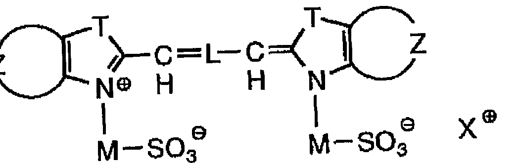


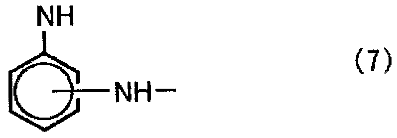


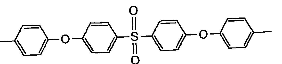


Claims


Priority Applications (3)
| Application Number | Priority Date | Filing Date | Title |
|---|---|---|---|
| EP20030715666 EP1491355A1 (en) | 2002-04-01 | 2003-03-31 | Multicolor image forming material |
| KR10-2004-7015703A KR20040102067A (en) | 2002-04-01 | 2003-03-31 | Multicolor image forming material |
| US10/509,798 US7112396B2 (en) | 2002-04-01 | 2003-03-31 | Multicolor image forming material |
Applications Claiming Priority (8)
| Application Number | Priority Date | Filing Date | Title |
|---|---|---|---|
| JP2002-98802 | 2002-04-01 | ||
| JP2002098802A JP2003291544A (en) | 2002-04-01 | 2002-04-01 | Multi-color image forming material |
| JP2002-152500 | 2002-05-27 | ||
| JP2002152500A JP2003341248A (en) | 2002-05-27 | 2002-05-27 | Multicolor image forming material |
| JP2002216943A JP2004058325A (en) | 2002-07-25 | 2002-07-25 | Multicolor image forming material |
| JP2002217154A JP2004058333A (en) | 2002-07-25 | 2002-07-25 | Multicolor image forming material |
| JP2002-216943 | 2002-07-25 | ||
| JP2002-217154 | 2002-07-25 |
Publications (2)
| Publication Number | Publication Date |
|---|---|
| WO2003086773A1 true WO2003086773A1 (en) | 2003-10-23 |
| WO2003086773A8 WO2003086773A8 (en) | 2005-01-13 |
Family
ID=29255479
Family Applications (1)
| Application Number | Title | Priority Date | Filing Date |
|---|---|---|---|
| PCT/JP2003/004106 WO2003086773A1 (en) | 2002-04-01 | 2003-03-31 | Multicolor image forming material |
Country Status (4)
| Country | Link |
|---|---|
| US (1) | US7112396B2 (en) |
| EP (1) | EP1491355A1 (en) |
| KR (1) | KR20040102067A (en) |
| WO (1) | WO2003086773A1 (en) |
Families Citing this family (8)
| Publication number | Priority date | Publication date | Assignee | Title |
|---|---|---|---|---|
| JP2005275170A (en) * | 2004-03-25 | 2005-10-06 | Fuji Photo Film Co Ltd | Dye containing negative type curable composition, color filter, and method for manufacturing color filter |
| DE102007005917A1 (en) * | 2007-02-01 | 2008-08-07 | Leonhard Kurz Gmbh & Co. Kg | Colored marking and labeling by means of high-energy radiation |
| EP1974948A3 (en) * | 2007-03-29 | 2012-02-08 | FUJIFILM Corporation | Image-forming method using heat-sensitive transfer system |
| CN102803409B (en) | 2009-06-26 | 2014-06-11 | 惠普发展公司,有限责任合伙企业 | Ink-jet inks having polymers and near-infrared absorbing dyes |
| WO2012091243A1 (en) | 2010-12-27 | 2012-07-05 | 제일모직 주식회사 | Thermal transfer film |
| KR101340548B1 (en) * | 2010-12-30 | 2013-12-11 | 제일모직주식회사 | Light-to-heat conversion layer and thermal transfer film comprising the same |
| EP2628603A4 (en) * | 2011-09-30 | 2015-01-28 | Dainippon Ink & Chemicals | Resin composition for forming receiving layer, receiving substrate obtained using same, printed matter, conductive pattern, and electrical circuit |
| JP5752652B2 (en) * | 2012-08-29 | 2015-07-22 | 富士フイルム株式会社 | Ink jet ink composition and method for producing the same, ink jet recording method, and pigment dispersion and method for producing the same |
Citations (3)
| Publication number | Priority date | Publication date | Assignee | Title |
|---|---|---|---|---|
| JPH11334231A (en) * | 1998-05-22 | 1999-12-07 | Fuji Photo Film Co Ltd | Thermal transfer sheet |
| JPH11348438A (en) * | 1998-06-04 | 1999-12-21 | Dainippon Printing Co Ltd | Laser thermal transfer recording material and method for laser thermal transfer recording |
| JP2002362045A (en) * | 2001-06-12 | 2002-12-18 | Konica Corp | Ink sheet for laser heat transfer and image recording method using the ink sheet |
Family Cites Families (10)
| Publication number | Priority date | Publication date | Assignee | Title |
|---|---|---|---|---|
| DE3781067T2 (en) * | 1986-09-01 | 1993-01-21 | Tomoegawa Paper Mfg Co Ltd | TRANSFER RECORDING MEANS AND THEIR USE FOR TRANSFER RECORDING METHODS. |
| JP3538653B2 (en) | 1995-03-31 | 2004-06-14 | コニカミノルタホールディングス株式会社 | Recording medium and image recording method |
| JPH0911646A (en) * | 1995-06-30 | 1997-01-14 | Fuji Photo Film Co Ltd | Thermal transfer sheet |
| JP3866411B2 (en) | 1998-05-22 | 2007-01-10 | 富士フイルムホールディングス株式会社 | Thermal transfer sheet |
| JP3437504B2 (en) * | 1998-12-01 | 2003-08-18 | 富士写真フイルム株式会社 | Thermal transfer sheet |
| JP2000351282A (en) | 1999-06-11 | 2000-12-19 | Fuji Photo Film Co Ltd | Thermal transfer sheet |
| US6458504B2 (en) * | 2000-04-28 | 2002-10-01 | Fuji Photo Film Co., Ltd. | Method for forming an image |
| US6864033B2 (en) * | 2001-01-24 | 2005-03-08 | Fuji Photo Film Co., Ltd. | Multicolor image-forming material |
| JP2002274069A (en) | 2001-03-19 | 2002-09-25 | Fuji Photo Film Co Ltd | Multi-color image forming material and multi-color image forming method |
| JP3970117B2 (en) * | 2001-07-19 | 2007-09-05 | 株式会社リコー | Thermoreversible recording medium, label, card, disk cartridge, disk, tape cassette, and image recording / erasing method |
-
2003
- 2003-03-31 US US10/509,798 patent/US7112396B2/en not_active Expired - Fee Related
- 2003-03-31 WO PCT/JP2003/004106 patent/WO2003086773A1/en not_active Application Discontinuation
- 2003-03-31 KR KR10-2004-7015703A patent/KR20040102067A/en not_active Application Discontinuation
- 2003-03-31 EP EP20030715666 patent/EP1491355A1/en not_active Withdrawn
Patent Citations (3)
| Publication number | Priority date | Publication date | Assignee | Title |
|---|---|---|---|---|
| JPH11334231A (en) * | 1998-05-22 | 1999-12-07 | Fuji Photo Film Co Ltd | Thermal transfer sheet |
| JPH11348438A (en) * | 1998-06-04 | 1999-12-21 | Dainippon Printing Co Ltd | Laser thermal transfer recording material and method for laser thermal transfer recording |
| JP2002362045A (en) * | 2001-06-12 | 2002-12-18 | Konica Corp | Ink sheet for laser heat transfer and image recording method using the ink sheet |
Also Published As
| Publication number | Publication date |
|---|---|
| EP1491355A1 (en) | 2004-12-29 |
| KR20040102067A (en) | 2004-12-03 |
| US7112396B2 (en) | 2006-09-26 |
| US20050153229A1 (en) | 2005-07-14 |
| WO2003086773A8 (en) | 2005-01-13 |
Similar Documents
| Publication | Publication Date | Title |
|---|---|---|
| WO2003086773A1 (en) | Multicolor image forming material | |
| JP4007601B2 (en) | Multicolor image forming material | |
| JP2004090287A (en) | Multi-color imaging material and multi-color imaging method | |
| WO2002096667A1 (en) | Laser thermal transfer recording method | |
| JP3425564B2 (en) | Multicolor image forming material and multicolor image forming method | |
| JP3425565B2 (en) | Multicolor image forming material and multicolor image forming method | |
| JP2005022366A (en) | Material and method for multicolor image forming | |
| JP2004025595A (en) | Forming method for glossy image | |
| JP2003089275A (en) | Multi-color imaging method | |
| JP2003054132A (en) | Multicolor image forming method | |
| JP3429298B2 (en) | Multicolor image forming method and multicolor image forming material | |
| JP2003341244A (en) | Thermal transfer sheet, image forming material, and image forming method | |
| JP3429284B2 (en) | Multicolor image forming material, multicolor image forming method, and multicolor image forming apparatus | |
| JP3470893B2 (en) | Thermal transfer sheet | |
| JP2004358688A (en) | Imaging method and color filter forming method | |
| JP2004284155A (en) | Thermal transfer recording material | |
| JP2004268289A (en) | Imaging layer support sheet, imaging layer coating liquid and imaging method | |
| JP2003175682A (en) | Image forming material | |
| JP2003266961A (en) | Material for forming multicolor image | |
| JP2004358839A (en) | Thermal transfer sheet and image forming method | |
| JP2003291544A (en) | Multi-color image forming material | |
| JP2004042316A (en) | Multicolor image forming material | |
| JP2003266955A (en) | Material and method for forming multicolor image | |
| JP2003054139A (en) | Multi-color imaging material | |
| JP2003231361A (en) | Multi-color image forming method |
Legal Events
| Date | Code | Title | Description |
|---|---|---|---|
| AK | Designated states |
Kind code of ref document: A1 Designated state(s): CN KR US |
|
| AL | Designated countries for regional patents |
Kind code of ref document: A1 Designated state(s): AT BE BG CH CY CZ DE DK EE ES FI FR GB GR HU IE IT LU MC NL PT SE SI SK TR |
|
| 121 | Ep: the epo has been informed by wipo that ep was designated in this application | ||
| DFPE | Request for preliminary examination filed prior to expiration of 19th month from priority date (pct application filed before 20040101) | ||
| WWE | Wipo information: entry into national phase |
Ref document number: 2003715666 Country of ref document: EP Ref document number: 10509798 Country of ref document: US |
|
| WWE | Wipo information: entry into national phase |
Ref document number: 1020047015703 Country of ref document: KR |
|
| WWE | Wipo information: entry into national phase |
Ref document number: 20038079496 Country of ref document: CN |
|
| DFPE | Request for preliminary examination filed prior to expiration of 19th month from priority date (pct application filed before 20040101) | ||
| WWP | Wipo information: published in national office |
Ref document number: 1020047015703 Country of ref document: KR |
|
| WWP | Wipo information: published in national office |
Ref document number: 2003715666 Country of ref document: EP |
|
| CFP | Corrected version of a pamphlet front page | ||
| CR1 | Correction of entry in section i |
Free format text: IN PCT GAZETTE 43/2003 UNDER (84) ADD "EP (RO)" |
|
| WWW | Wipo information: withdrawn in national office |
Ref document number: 2003715666 Country of ref document: EP |