WO2002044920A1 - Load balancing in set top cable box environment - Google Patents

Load balancing in set top cable box environment Download PDF

Info

Publication number
WO2002044920A1
WO2002044920A1 PCT/US2001/043136 US0143136W WO0244920A1 WO 2002044920 A1 WO2002044920 A1 WO 2002044920A1 US 0143136 W US0143136 W US 0143136W WO 0244920 A1 WO0244920 A1 WO 0244920A1
Authority
WO
WIPO (PCT)
Prior art keywords
router
message
network
messages
hgs
Prior art date
Application number
PCT/US2001/043136
Other languages
French (fr)
Inventor
Lee Kamentsky
Peter Hall
Chaitanya Kanojia
Original Assignee
Navic Systems, Inc.
Priority date (The priority date is an assumption and is not a legal conclusion. Google has not performed a legal analysis and makes no representation as to the accuracy of the date listed.)
Filing date
Publication date
Priority claimed from US09/999,718 external-priority patent/US7653743B2/en
Priority claimed from US10/003,805 external-priority patent/US7047273B2/en
Application filed by Navic Systems, Inc. filed Critical Navic Systems, Inc.
Priority to CA2430125A priority Critical patent/CA2430125C/en
Priority to EP01998903A priority patent/EP1344144B1/en
Publication of WO2002044920A1 publication Critical patent/WO2002044920A1/en

Links

Classifications

    • HELECTRICITY
    • H04ELECTRIC COMMUNICATION TECHNIQUE
    • H04LTRANSMISSION OF DIGITAL INFORMATION, e.g. TELEGRAPHIC COMMUNICATION
    • H04L12/00Data switching networks
    • H04L12/28Data switching networks characterised by path configuration, e.g. LAN [Local Area Networks] or WAN [Wide Area Networks]
    • H04L12/2854Wide area networks, e.g. public data networks
    • H04L12/2856Access arrangements, e.g. Internet access
    • H04L12/2869Operational details of access network equipments
    • H04L12/2898Subscriber equipments
    • HELECTRICITY
    • H04ELECTRIC COMMUNICATION TECHNIQUE
    • H04LTRANSMISSION OF DIGITAL INFORMATION, e.g. TELEGRAPHIC COMMUNICATION
    • H04L45/00Routing or path finding of packets in data switching networks
    • H04L45/58Association of routers
    • HELECTRICITY
    • H04ELECTRIC COMMUNICATION TECHNIQUE
    • H04LTRANSMISSION OF DIGITAL INFORMATION, e.g. TELEGRAPHIC COMMUNICATION
    • H04L47/00Traffic control in data switching networks
    • H04L47/10Flow control; Congestion control
    • H04L47/12Avoiding congestion; Recovering from congestion
    • H04L47/125Avoiding congestion; Recovering from congestion by balancing the load, e.g. traffic engineering
    • HELECTRICITY
    • H04ELECTRIC COMMUNICATION TECHNIQUE
    • H04LTRANSMISSION OF DIGITAL INFORMATION, e.g. TELEGRAPHIC COMMUNICATION
    • H04L61/00Network arrangements, protocols or services for addressing or naming
    • HELECTRICITY
    • H04ELECTRIC COMMUNICATION TECHNIQUE
    • H04LTRANSMISSION OF DIGITAL INFORMATION, e.g. TELEGRAPHIC COMMUNICATION
    • H04L61/00Network arrangements, protocols or services for addressing or naming
    • H04L61/09Mapping addresses
    • H04L61/10Mapping addresses of different types
    • HELECTRICITY
    • H04ELECTRIC COMMUNICATION TECHNIQUE
    • H04LTRANSMISSION OF DIGITAL INFORMATION, e.g. TELEGRAPHIC COMMUNICATION
    • H04L61/00Network arrangements, protocols or services for addressing or naming
    • H04L61/45Network directories; Name-to-address mapping
    • HELECTRICITY
    • H04ELECTRIC COMMUNICATION TECHNIQUE
    • H04LTRANSMISSION OF DIGITAL INFORMATION, e.g. TELEGRAPHIC COMMUNICATION
    • H04L61/00Network arrangements, protocols or services for addressing or naming
    • H04L61/50Address allocation
    • HELECTRICITY
    • H04ELECTRIC COMMUNICATION TECHNIQUE
    • H04LTRANSMISSION OF DIGITAL INFORMATION, e.g. TELEGRAPHIC COMMUNICATION
    • H04L67/00Network arrangements or protocols for supporting network services or applications
    • H04L67/01Protocols
    • H04L67/10Protocols in which an application is distributed across nodes in the network
    • HELECTRICITY
    • H04ELECTRIC COMMUNICATION TECHNIQUE
    • H04LTRANSMISSION OF DIGITAL INFORMATION, e.g. TELEGRAPHIC COMMUNICATION
    • H04L67/00Network arrangements or protocols for supporting network services or applications
    • H04L67/2866Architectures; Arrangements
    • H04L67/30Profiles
    • H04L67/303Terminal profiles
    • HELECTRICITY
    • H04ELECTRIC COMMUNICATION TECHNIQUE
    • H04LTRANSMISSION OF DIGITAL INFORMATION, e.g. TELEGRAPHIC COMMUNICATION
    • H04L67/00Network arrangements or protocols for supporting network services or applications
    • H04L67/2866Architectures; Arrangements
    • H04L67/30Profiles
    • H04L67/306User profiles
    • HELECTRICITY
    • H04ELECTRIC COMMUNICATION TECHNIQUE
    • H04LTRANSMISSION OF DIGITAL INFORMATION, e.g. TELEGRAPHIC COMMUNICATION
    • H04L67/00Network arrangements or protocols for supporting network services or applications
    • H04L67/50Network services
    • H04L67/51Discovery or management thereof, e.g. service location protocol [SLP] or web services
    • HELECTRICITY
    • H04ELECTRIC COMMUNICATION TECHNIQUE
    • H04LTRANSMISSION OF DIGITAL INFORMATION, e.g. TELEGRAPHIC COMMUNICATION
    • H04L67/00Network arrangements or protocols for supporting network services or applications
    • H04L67/50Network services
    • H04L67/535Tracking the activity of the user
    • HELECTRICITY
    • H04ELECTRIC COMMUNICATION TECHNIQUE
    • H04LTRANSMISSION OF DIGITAL INFORMATION, e.g. TELEGRAPHIC COMMUNICATION
    • H04L67/00Network arrangements or protocols for supporting network services or applications
    • H04L67/50Network services
    • H04L67/55Push-based network services
    • HELECTRICITY
    • H04ELECTRIC COMMUNICATION TECHNIQUE
    • H04LTRANSMISSION OF DIGITAL INFORMATION, e.g. TELEGRAPHIC COMMUNICATION
    • H04L67/00Network arrangements or protocols for supporting network services or applications
    • H04L67/50Network services
    • H04L67/60Scheduling or organising the servicing of application requests, e.g. requests for application data transmissions using the analysis and optimisation of the required network resources
    • H04L67/62Establishing a time schedule for servicing the requests
    • HELECTRICITY
    • H04ELECTRIC COMMUNICATION TECHNIQUE
    • H04LTRANSMISSION OF DIGITAL INFORMATION, e.g. TELEGRAPHIC COMMUNICATION
    • H04L67/00Network arrangements or protocols for supporting network services or applications
    • H04L67/50Network services
    • H04L67/60Scheduling or organising the servicing of application requests, e.g. requests for application data transmissions using the analysis and optimisation of the required network resources
    • H04L67/63Routing a service request depending on the request content or context
    • HELECTRICITY
    • H04ELECTRIC COMMUNICATION TECHNIQUE
    • H04LTRANSMISSION OF DIGITAL INFORMATION, e.g. TELEGRAPHIC COMMUNICATION
    • H04L69/00Network arrangements, protocols or services independent of the application payload and not provided for in the other groups of this subclass
    • H04L69/30Definitions, standards or architectural aspects of layered protocol stacks
    • H04L69/32Architecture of open systems interconnection [OSI] 7-layer type protocol stacks, e.g. the interfaces between the data link level and the physical level
    • H04L69/322Intralayer communication protocols among peer entities or protocol data unit [PDU] definitions
    • H04L69/329Intralayer communication protocols among peer entities or protocol data unit [PDU] definitions in the application layer [OSI layer 7]
    • HELECTRICITY
    • H04ELECTRIC COMMUNICATION TECHNIQUE
    • H04LTRANSMISSION OF DIGITAL INFORMATION, e.g. TELEGRAPHIC COMMUNICATION
    • H04L67/00Network arrangements or protocols for supporting network services or applications
    • H04L67/01Protocols
    • H04L67/10Protocols in which an application is distributed across nodes in the network
    • H04L67/1001Protocols in which an application is distributed across nodes in the network for accessing one among a plurality of replicated servers
    • H04L67/10015Access to distributed or replicated servers, e.g. using brokers

Definitions

  • CATV cable television
  • the digital set top box provides certain interesting functionalities, such as the ability to collect data, such as a log of the channels watched over time, and other events.
  • the set top box can be designed and program to them report this information to a central location. At the central location, this data can be aggregated for many hundreds of thousands of users.
  • This information when coupled with other information such as demographics, can then be used by advertisers and service providers to blanket defined market segments with promotions, advertisements, and content.
  • the digital delivery of promotions can then allow for impulse responses yielding immediate increases in revenues.
  • such a network may have hundreds of thousands, if not millions of set top boxes, attempting to deliver event log information. If such a data network were built using standard data protocols such as TCP/TP, the sheer number of connection request messages alone could cause the performance of a central data server to degrade to the point where it is unable to carry out reliable message delivery.
  • TCP/TP standard data protocols
  • the present invention implements a scalable messaging system for data transmission between the network devices, such as set top boxes, and a central system server, such as a server which maintains a database of event logs for the network.
  • the individual routers at the data center broadcast an announcement packet indicating that they are available to accept messages from the network devices.
  • the announcement message contains at least an identification of the router and the manner in which messages may be sent to it, e.g., one or more connection socket numbers and/or network addresses.
  • the frequency at which these availability messages are sent by the routers is preferably dependent upon the relative loading of the individual router. Thus, the more heavily loaded a particular router becomes, the less often it will broadcast an availability message; the more lightly loaded it becomes, the more often such messages are broadcast.
  • the network devices then transmit messages to the data center only in response to having received such a router availability announcement.
  • the information in a router availability message can be used in various ways to construct a payload message back to the data center, such as by using ports numbers, persistent identification numbers, or Media Access Control (MAC) layer addresses.
  • MAC Media Access Control
  • This protocol thus permits control over the generation of messages, such as connection request messages, which originate at the network devices. It avoids a situation whereby such messages might otherwise tend to flood a network that consists of an extremely large number of end nodes that need to communicate to a central location.
  • the implementation of a device management protocol in this manner assists network operators to cost effectively support the advanced features of the set-top box, such as to provide targeted promotion and digital content distribution services. This enables network operators to generate new revenues and provide a richer interactive environment for consumers.
  • Fig. 1 is a block diagram of a network in which a messaging protocol according to the invention may be used to control the transmission of messages from an extremely large number of transmitting network devices to a central receiver location.
  • Fig. 2 is a high level process flow diagram of a particular application which makes use of the protocol to deliver targeted promotions and content.
  • Figs. 3 A and 3B are a process flow diagram illustrating how a router processes different types of messages.
  • Fig. 4 illustrates a Global Unique Identifier assigned to the network devices so that they may be addressed by an application.
  • Fig. 5 is a high level router state diagram.
  • Fig. 6 is a high level state diagram for how a router handles network device connections.
  • Fig. 7 is a high level message state diagram.
  • Fig. 8 is an exemplary router announcement service message.
  • Figs. 9A, 9B, and 9C are different types of device connection messages returned in response to the router announcement service message.
  • Fig. 1 illustrates a multimedia content delivery system which uses a message routing protocol according to one embodiment of the present invention.
  • the system includes a large number of set top boxes or network devices 10 connected to respective video displays 20, such as televisions.
  • Promotions 30 typically include promotional content that may be presented in various multimedia formats including standard audio visual clips, but also computer graphics, icons, or Hypertext Markup Language (HTML) content. Promotions are used to advertise goods and services, promote events, or present other commercial or non-commercial information.
  • One or more promotions 30 may be simultaneously active within the video displays 20 and may be displayed in different ways. For example, promotions 30 can be presented on electronic program guides, channel information bars, or by overlaying video broadcast programming. Some active promotions that may be displayed on digital set top boxes allow user interaction such as linking to e-commerce web-sites via hyperlink connections or direct communication with the server subsystem of the promotion delivery system to obtain additional software, such as device drivers, video games, or other application software.
  • the network devices also include a promotion server subsystem 200 located at a data center, and a promotion agent subsystem 300 embedded within each of the network devices.
  • the promotion server subsystem 200 and the promotion agent subsystems 300 communicate with each other through a combination of application-level messaging and serialized bulk data transmissions.
  • the promotion server subsystem 200 periodically collects viewer usage data from the promotion agent subsystem 300 of each of the multimedia content viewing devices to generate viewership profiles.
  • the data collected by the promotion server subsystem 200 may include tuner data (i. e. , a history of channels watched) and responses to past promotions. This history is kept on a relatively fine time scale, such as five seconds, hi this way, it can be determined how long a particular promotion was deployed, or even which portions of a promotion or video program were viewed.
  • the promotion server subsystem 200 includes a database server 210, a promotion manager server 220, a bulk data server 230, a promotion manager client 240, a life-cycle manager server 240, and a bank of routers 250-1, 250-2, ..., 250-n, and a queue manager 260.
  • These components are typically located at a central location in the multimedia network at a data center, at a head end, or divided between the two depending on the density and population of devices. It should be understood that these components may share physical platforms or de distributed across multiple machines located at different places in the network.
  • a promotion packaging process in the promotion manager server 220 may be separated from a function which is responsible for delivering promotion packages to the network devices 10.
  • the delivery function may be instantiated on multiple machines, for example, to provide better scalability, such as having one machine per head end in the network.
  • the life cycle manager 240 may also be instantiated separately for each router 250.
  • the routers 250 communicate with the network devices 10 through a data network 75 which may itself include a further hierarchy of routers and bulk servers (not shown in Fig. 1). Ultimately, each of the network devices is connected to the network 75 through a head end location 50. hi a typical cable television network, there maybe many thousands of network devices connected to a particular head end, and there may be many thousands of head ends 50.
  • the queue manager 260 is provided for facilitating the transfer of messages between the message routers 250 and the other system components.
  • the queue manager 2600 is an application-level process that communicates with the message routers 250 on behalf of other processes, such as the promotion manager 220, or the promotion agent in the network device 300, in order to send and receive messages among them.
  • the queue manager 260 is implemented as a C++ object.
  • the queue manager 260 also manages incoming and outgoing messages queues on behalf of the processes in the system process running at the data center 200.
  • the queue manager 260 handles two types of queues, persistent queues and volatile queues. Messages, whose message type indicates persistent storage, are stored such that the message will not be lost during power outages and lost network connections. A persistent queue is stored in persistent flash memory or in a location on the hard disk of the network device. Other messages, not intended for persistent storage, are stored to volatile queues and might be lost during power outage and lost network connections. To determine how to deliver targeted promotions to the network devices, the life-cycle manager server 240 of the promotion server subsystem 200 first generates viewership profiles for each of the multimedia content viewing devices from the collected data using a variety of statistical models. The viewership profiles are then used to associate groups of network devices with a given target promotion.
  • Promotion groups are collections of multimedia content viewing devices whose individual viewership profiles match membership criterion describing a particular demographic or viewership history.
  • a promotion group may be demographically based, i.e., "married women in their 30's with more than one school age child and a household income of at least $100,0000," or based on viewership history, i.e., "tends to watch the Golf Channel on Sunday afternoon.” Therefore, the promotion delivery system is adaptable to changes in viewer usage or viewership patterns by making adjustments to promotion groups. Promotion groups are described in more detail in U.S. Provisional Patent Application Serial No. 60/253,488 filed November 28, 2000, entitled “Using Viewership Profiles for Targeted Promotion Deployment.”
  • Promotions are then scheduled for delivery to specific promotion groups.
  • a promotion is scheduled for delivery to a promotion group by an advertiser or service provider entering a scheduling request for a promotion such as via a promotion manager interface client 225.
  • the promotion manager server 220 packages the promotion for delivery and stores it in the database 210. Later, the package information is read from the database 210 and used to create customized transmission schedules that specify when and how each of the network devices 10 is to receive it.
  • a preferred technique for packaging ' promotions into messages to be sent to the network devices is described in U.S. Provision Patent Application Serial No. 60/253,489 filed November 28, 2000, entitled "Promotion Packaging for Transmission Groups.”
  • the promotion agent subsystem 300 embedded in each of the network devices 10 includes apromotion agent 310 and a bulk data agent 320.
  • the promotion agent 310 processes each schedule entry and waits for the bulk data agent 320 to deliver each promotion identified in the transmission schedule.
  • the bulk data agent 320 then handles the reception of the promotions from the scheduled data transmission as specified in the promotion download requests. For example, in one embodiment, the bulk data agent 320 tunes into a multicast data transmission stream at a specified time and channel or network address specified in the transmission schedule.
  • the promotion manager server 220 extracts the promotion package from the database 210 and converts it into a transmission request that is sent to the bulk data server 230.
  • the bulk data server 230 fetches the promotions from the database 210 that are identified in the transmission request message, and transmits them via multicast or broadcast transmission depending on transmission control data specified in the transmission request.
  • promotion activation may be event, time, or channel driven.
  • Fig. 2 illustrates a generalized process diagram 400 for creating a viewership profile of a viewer who has tuned to a program channel on a network device 10.
  • the promotion agent 310 of the promotion agent subsystem 300 embedded in the network device 10 creates an event log of the viewer's activities.
  • the event log records the channel to which the set top box is tuned to, the time the channel was tuned in, and the time the it left the channel.
  • the event is recorded only if the period between the time the viewer tuned in the channel and the time the viewer tuned away from the channel is greater than about five seconds.
  • the promotion agent is able to distinguish shows that are actually watched from channel "surfing" by the viewer.
  • the promotion agent 310 After the promotion agent 310 has logged viewer activities for a period time, such as twenty four hours, the logged activities are transmitted through messages, in a state 404, to the life cycle manager server 250.
  • the messages are transmitted through a messaging protocol for unicast transmission, such as TCP/IP.
  • the life cycle manager receives the event log from the promotion agent 310. Also, in the state 406 a program schedule 260 is periodically transmitted to the life cycle manager server 250. Such program schedule data for broadcast network is typically available from commercial services.
  • the life cycle manager server 250 After receiving the logged viewership activities and the program schedule 260, the life cycle manager server 250 correlates the data in the state 406.
  • the life cycle manager determines the viewer behavior associated with the network devices. The life cycle manager may for example, determine what programs were watched and the percentage of time each program was watched during its scheduled time slot.
  • the viewer behavior data generated by the life cycle manager server is matched with group profiles 270 provided by third parties, such as advertisers, to the life cycle manager server 250.
  • group profiles 270 may include age, gender, residence and other demographic data.
  • the matched viewership behavior data and group profiles 270 are used to select and then download a targeted promotion to the determined class of the viewer.
  • this promotion is delivered to the network devices 10.
  • messages are delivered to and from the data center and the network devices through the routers 250.
  • Messages come in two flavors: application and control.
  • the application messages deliver data content; control messages are used to co-ordinate delivery.
  • Application messages can have one of two delivery methods: Datagram and Standard. Standard messages guarantee persistence via a receipt control message. A message receiver sends a receipt to the sender for one of these messages as soon as the receiver has guaranteed that the message persists somewhere upstream of the sending device. Receipting or persistence functions are not performed for datagrams.
  • Each router 250 generally implements a protocol as follows:
  • the router forwards the message to that device and waits for the recipient to receipt the message.
  • the recipient If the recipient receipts the message within the time allotted, then the recipient has guaranteed that the message persists upstream of the router. The router then sends a receipt to the message's sender if required.
  • the router persists the message in the database. The router will periodically attempt to deliver the message until the message expires or until the recipient sends a receipt.
  • the router persists the message in the database and attempts to bring the device online.
  • the router will send the message to the destination device when it comes online and will attempt to deliver the message periodically until the message expires or until the recipient sends a receipt.
  • Figs. 3 A and 3B illustrate a generalized process flow diagram for the handling of messages by the routers 250.
  • a router 250 receives a message either from a device 10, from the database 210 or from another router 250 using a router-router protocol.
  • a delivery method message parameter indicates that the message is to be sent as a datagram, i.e, indicates that the message should not be persisted if currently undeliverable.
  • the router sends a receipt control message to the sending entity (if the message is from a network device). The receipt object is sent back to the originating sender if using the router-router protocol.
  • step 1105 a filter function is performed that removes improperly addressed router messages.
  • the only acceptable value is "Router”.
  • step 1106 the message is handled as if sent to the router's queue via the internal router queue manager.
  • Step 1107 is reached if the message had an improper queue name, at which point the message is discarded.
  • Step 1108 is reached if the message did not have the internal router identifier. In this step, it is determined whether the router ID portion of the device specified in the destination ID matches the router's router ID.
  • Step 1109 checks to see if the device indicated by the device ID portion has a TCP connection to this router.
  • step 1110 the message is sent to the device if connected.
  • Step llll checks to see if the router should discard a datagram sent to a device presumed to be offline.
  • Step 1112 persists standard messages to devices presumed to be offline. If the specified device is online with another router, that router will get the message via the database. Step 1113 discards datagrams to offline devices.
  • Step 1201 is reached if the message is not intended for the router itself.
  • the router checks to see if it is connected to the router indicated in the router ID portion of the device indicated in the message's destination ID.
  • step 1202 if the device is connected, the router sends message to one of the other routers 250 presumed to be the path to the specified device (a device could switch routers during the period between message creation and message delivery).
  • the router asks the database for the port and IP address on which to make a router-router connection to the destination device's router.
  • step 1204 check the database's query for a path to the destination device's router.
  • step 1205 if no such path exists, then persist message to database. If the device is online, its router will get the message from the database and deliver it.
  • step 1206 a TCP connection is made to the destination device's router.
  • Step 1207 checks for a connection success or failure (due to timeout, network error, etc.).
  • step 1208 the router persist the message to the database if the connection could not be established.
  • step 1209 if the connection succeeded, the message is sent to the destination device's router via the router-router protocol.
  • Router to router protocol extensions are implemented to permit the routers 250 to communicate with each other. This protocol follows the same basic principle as router/device communication. A receipt by a router indicates that the message has persisted somewhere upstream. In general, all routers try to forward messages outside of the database, but some database method of persistence has to be available in case the end device is offline. Router to router communication is different from device to router communication. In general, routers should always be online. Also, routers are a trusted entity within the system and have a less restricted network path to other routers. Router communication is tailored to these considerations. Routers are able to establish a privileged connection with other routers in order to forward messages.
  • This router-to-router protocol permits the routers to cooperate in order to coordinate the following tasks:
  • Device connection - the system provides centralization of device state within the database which maintains information as to which router on a head end connects to a particular network device 10.
  • the routers 250 recognize the database information as correct and synchronized.
  • Message exchange -the system also provides a mechanism other than the database for forwarding messages from a service attached to one router to a device attached to a different router and vice-versa.
  • Message persistence the system also provides a mechanism for persisting messages to offline devices.
  • Service location the system has a mechanism that allows devices to send messages to a service without knowing, a priori, which machine hosts the service.
  • Router performance the system is able to judge router load and maintains some indication as to whether the router is functioning properly.
  • Routers 250 in a multiple router system need to be able to associate a particular network device 10 with the routers that can connect or are connected to the device. This information is localized in a Global Unique Identifier (GUTD) assigned to each network device 10.
  • GUTD Global Unique Identifier
  • the use of a GUTD permits the application level processes to identify destination devices without the need to maintain information as to the specific types of transport in use, or a device's network address.
  • the device GUTD hold two pieces of routing information, the network ID and the router ID.
  • the network ID represents the set of routers that can connect to a given device.
  • the router ID represents the particular router in a network that is currently connected to a device. Each router has a unique combination of network and router ID information.
  • Devices have a device ID that uniquely identifies them.
  • Each device also has a network ID that identifies the sub-network head to which the device is connected.
  • the network ID is not necessarily permanent, since head end configurations may change, but the network ID should persist with the same value for a long period of time.
  • the network ID could also be a head end ID, but using network IDs accommodates a situation where multiple head ends are located in the same sub-network.
  • Each connected device also has a router ID that identifies the router that is attached to it. Together, the device ID, network ID and router ID make up the device GUTD, as shown in Fig. 4.
  • a service sending an unsolicited message to a device must get the device ID from some location; typically the database.
  • a function is provided in the database that generates a device's device GUTD given the device's device ID. Typically, stored procedures will use the device ID to join tables to the device table, but will write out the device GUTD when assembling the final output.
  • a device might not be online when the device GUTD function is called.
  • the device GUTD function will specify a router ID if none is currently specified and will mark the device as eligible to go online if it is not currently online. The system anticipates that a request for a device GUTD indicates that a message will soon be sent to it and tries to prepare the device appropriately.
  • the device GUTD function will contain load balancing logic. A device should be associated with the last router to service it, for consistency. A device should be associated with the router that has the least load. The device GUTD will weigh these two considerations, reassigning a device if its former router is offline or is experiencing a load that degrades its performance significantly in comparison to other routers on the head end.
  • This section documents database tables and stored procedures used by the routers 250.
  • Table 1 is a database table TJXETWORK that describes a network. Examples of networks are the data center, the network that the Multiple System Operator (MSO) exposes for control of devices, and the Internet at large.
  • MSO Multiple System Operator
  • T_ROUTER represents a router servicing devices or a service that makes connections to the router via the router-router connection.
  • each router periodically determines a relative load metric and stores this information in the LOAD_METRIC entry in the table.
  • a lower number indicates a better performing router.
  • the LOAD JVTETRIC entry is used by the router to determine how often to send an availability message to the network devices 10.
  • T_ROUTER_NIC Table 3, represents a network card in a router.
  • a router will have a network card with an TP address in the data center's firewalled network and one or more cards with P addresses in an MSO's network.
  • T_ROUTER_NIC_IN is populated on initialization. It tells the stored procedure, PKG HGS ROUTER.SP HGS INIT, what network cards exist on the router.
  • T_ROUTER_TUNING contains one row that maintains the router tuning parameters used in the database. These parameters are used in the stored procedures.
  • T_SERVICE_TYPE identifies a particular type of service supported through er-router connection.
  • T_DEVICE represents a device hosting a queue manager.
  • T_DEVICE contains information used by several different entities. The columns listed here are the only ones used by the router and its stored procedures.
  • the MAC address is a unique six byte address assigned to every Ethernet protocol network interface device. It uniquely identifies the device. Table 8, T_CONNECT_REQUESTJN is used by the router to transmit a set of connect requests to the database viaPKG_HGS_CONNECT.SP_HGS_CONNECT__REQUEST.
  • T_HGS_CONNECT_ACTIVITY_IN is used by the router to inform the database of the set of devices whose connect states have changed. The router populates this table and calls PKG_HGS_CONNECTION.SP_HGS_CONNECT_ACTTVITY to process the inserted rows.
  • TJVIESSAGE contains the routing and delivery information for a message.
  • T JPAYLOAD is a database entry which contains a portion of a message.
  • the router breaks a message into 256 byte chunks in order to optimize use of space when uploading messages.
  • a given message has one TJVTESSAGE row and usually 1-3, but sometimes up to 20 rows in the T PAYLOAD table.
  • T _MESSAGE_ACT-NITY_1N is used by the router to inform the database of messages sent and not sent.
  • the router creates a transaction GUTD and puts it in each row of T_MESSAGE_ACTTVITY_ ⁇ N, then calls PKG_HGS_MESSAGE.SP_HGS_ RECORD_MESSAGE_ACTIVITY to process the results.
  • the router's stored procedures are contained in three packages,
  • PKG__HGS_ROUTER contains the stored procedures that bring a router online, that take the router offline, that reset the watchdog timer, and that find other routers.
  • a generalized router state diagram for these procedures is illustrated in Fig. 5.
  • the states of the router device include an offline state 1500, a running state 1510, and a disconnect scheduled state 1520.
  • the PKG_HGS_ROUTER software package contains these and other stored procedures. For example:
  • SP_HGS_TNIT The router calls this stored procedure when it comes online.
  • the procedure has five purposes: o To create a new entry in T_ROUTER for routers that are connecting for the first time. o To initialize device states (if a network has only one router and the router terminates without calling SP_HGS_EXIT, device connect states may hold the erroneous STATUS_ONLTNE at the time SP_HGS_TNIT is called. o To mark the router as online. o To create new entries in the T_ROUTER_NIC table for new network cards. o To record the current IP addresses of the router's network cards, o To return the configuration information for the router's network cards.
  • a router creates one row in the T_ROUTER_NTCJLN table for each of its network cards. All rows should contain the same transaction GUTD. This GUTD is passed into SP_HGS_TNIT to update its T_ROUTER_NIC table.
  • SP_HGS_WATCHDOG - this stored procedure has several different functions: o It records the fact that the router is still active. o It updates the router's load metric and adjusts network card configuration based on this metric, o It takes routers that are inactive (e.g. because they terminated unexpectedly, were isolated from the database, were deadlocked) offline. This also marks all devices assigned to the inactive router as offline, o It transmits the router' s network card configuration, allowing the router to update any changes.
  • the stored procedure has the following parameters:
  • each router periodically determines a relative load metric and stores this information in the LOAD_METRIC.
  • a lower number indicates a better performing router.
  • the LOAD_METRIC entry is used by the router to determine how often to send an availability message to the network devices 10.
  • SP_HGS_EXIT this stored procedure is called as its last database communication before terminating. It has the following functions: o It marks the router as offline. o It sets the device connect state of any devices connected to the router as offline. SP_HGS_EXIT has the following parameters:
  • a state 1600 is an offline state
  • state 1610 is entered when a connection request is received in the offline state
  • state 1620 is an online state
  • state 1630 is an online connection request state
  • state 1640 is entered when the router is disconnecting and receives a connection request.
  • PKG_HGS_ CONNECTION contains the stored procedures to record connection requests from devices, to inform routers of devices requiring connection and to record the connection state of these devices.
  • PKG_HGS_CONNECTION has the following stored procedures that are called from the C++ router:
  • PKG_HGS_CONNECTION also contains a stored procedure, SP_HGS_ONE_CONNECT_REQUEST, that maybe called externally by other stored procedures to bring a device online. This may be done to prepare the device to receive messages from a service.
  • SP_HGS_CONNECT_REQUEST This stored procedure records connection requests from devices. Devices send their IP address and listener port when they have messages to send to a router. The stored procedure records these in the database. The router creates rows in the T_CONNECT_REQUEST_TN table, then calls SP_HGS_CONNECT_REQUEST to process the requests.
  • SP_HGS_CONNECT_REQUEST has the following functions:
  • SP_HGS_CONNECT_REQUEST will do this for devices which do not transmit a MAC address or device ID (indicating that they don't know either quantity) or that transmit MAC addresses or device Ids that aren't in the T_DENICE table.
  • SP_HGS_CO ⁇ ECT_REQUEST has the following parameters:
  • SP_HGS_CONNECT The router calls this stored procedure to get the set of devices requiring connection because of connection requests. This includes connection requests from SP_HGS_CONNECT_REQUEST and those due to messages being sent to offline devices. These are cases requiring relatively immediate response. SP_HGS_CONNECT returns a cursor containing the information needed to connect.
  • the procedure has the following parameters:
  • SP_HGS_MSG_CONNECT this stored procedure returns the set of connections to be made to devices with messages pending. This call should be made less frequently than SP_HGS_CONNECT (and, if possible, with lower priority) because it is relatively expensive compared to SP_HGS_CONNECT and because the connections do not need to be made in a timely fashion.
  • SP_HGS_MSG_CONNECT has the same parameter signature as SP_HGS_CONNECT.
  • SP_HGS_DISCONNECT this stored procedure returns the set of stale device connections. The router should attempt to disconnect from these devices.
  • SP_HGS_DIS CONNECT has the same parameter signature as SP_HGS_CONNECT.
  • SP_HGS_CONNECT_ACTIVITY the router updates the connection state in T_DEVICE using this stored procedure.
  • the router inserts rows into T_HGS_CONNECT_ACTIVITY_ ⁇ N. Each row contains a transaction GUTD which correlates the row with the particular invocation of SP_HGS_CONNECT_ACTINITY.
  • SP_HGS_CO ⁇ ECT_ACTIVITY updates T_DEVICE.CONNECT_STATE for each row processed, deletes the row and sends a result code in CURS_ACTTVITY_PARAM which is returned from the stored procedure.
  • T_HGS_CONNECT_ACTTVITY_TN are identified by the router by this GUTD.
  • T_HGS_CONNECT_ACTIVITY_ ⁇ N to indicate success or failure of the operation.
  • SP_HGS_ONE_CONNECT_REQUEST this stored procedure makes a connect request on behalf of some other stored procedure. It operates similarly to SP_HGS_CONNECT_REQUEST (in fact it provides the implementation for SP_HGS_CONNECT_REQUEST in the current, but not subsequent, code base). It has the following parameters:
  • the routers 250 of course also handle the processing of messages. This process is shown generally in Fig. 7, and includes a status not sent state 1700, a status sending state 1710, a status failed sending state 1720, and a status message deleted state 1730.
  • the stored procedure PKG_HGS_MESSAGE contains the program code that verify incoming messages, that pick messages eligible for transmission, that update message state, and that delete messages.
  • the following messages are intended for external access:
  • SP_HGS_GET_MESSAGES the router retrieves the set of messages to process via this stored procedure.
  • the stored procedure returns a cursor of payloads; these payloads are ordered by message ID and then by payload item index.
  • SP_HGS_ GET_MESSAGES changes the message state to STATUS_SEND_TN_PROGRESS for outgoing messages to prevent a resend.
  • SP_HGS_GET_MESSAGES has the following parameters:
  • SP_HGS_RECORD_MESSAGE_ACTIVITY this stored procedure records the result of an attempt to send a message retrieved via SP_HGS_GET_MES SAGES.
  • the router inserts rows into T_MESSAGE_ACT ⁇ VITY_IN indicating the results of a transfer attempt. It marks each row in this table with a transaction GUTD which it passes into •
  • SP_HGS_RECORD_MESSAGE_ACT ⁇ VITY deletes any messages marked as sent and sets the send state of any unsent messages to STATUS_SEND_FATLED.
  • SP_HGS_RECORD_MESSAGE_ACTIVITY has the following parameters:
  • a device may broadcast its device connection packet in certain limited instances, such as if it is less than one network hop from a router.
  • DNS or static IP A device may send a connection packet to a router known to be at a particular DNS or static IP address.
  • Multicast or broadcast availability This is the most common case and the one to which the present invention is directed.
  • a router announcer process multicasts or broadcasts a list of routers that can be sent connection requests.
  • the multicast or broadcast takes place on a known TP address and port, using a UDP protocol.
  • the payload portion of such a router announcement service UDP packet is shown in Fig. 8.
  • the packet includes at least an identifier field 500 indicating the type of packet, e.g., that this is a router announcement packet.
  • a field of 128 bits is allocated for the identifier field 500 in this embodiment.
  • a time field 510 indicating the time of the announcement, and a port number 520 for establishing a connection to the router, are also included.
  • the time field 510 supports synchronization of events within the entire system as well as security functions.
  • the port number provides the port used to address the packet to the router process. A separate network address for the router need not be specified in the payload portion of the packet, since this information can be gleaned from the UDP header information (not shown in Fig. 7).
  • the system allows provisioning for more than one router as equally preferred. For instance, if two routers are at a particular location, then they can each send availability messages. Devices would be as likely to receive one packet as the other.
  • the preferred port number of the router announcer is 18505.
  • the preferred port for connection requests on the router is 18503.
  • the network devices can then request that they be permitted to connect to the announcing router. This takes the form of a device connection UDP packet.
  • the packet itself contains enough information to discern at least the requesting device's IP address.
  • Figs. 9A, 9B, and 9C There are three cases for the device connect messages shown respectively in Figs. 9A, 9B, and 9C.
  • the network device does not know its device ID or MAC address. This can be used as an initial provisioning case for devices with inaccessible MAC addresses.
  • the network device knows its MAC address. This is the preferred case as it allows the server to change the device's device ID.
  • the device has cached its device ID from a previous call.
  • the payload portion of the packet data provides the port number and device ID or MAC address for the device, as used by the router in establishing the connection to the requesting network device.
  • a given one of the routers will respond by connecting to the network device 10.
  • the router preferably sends a clock message as the first message to the device.
  • the clock message contains the network device's assigned GUTD in the message header field,.
  • the device can then use this GUTD as its sender identification for subsequent messages.
  • the clock message can contain a device TD different from the one sent in the case where the MAC address is unknown.
  • the device will persist the new device ID and use it in subsequent device connections.
  • the particular router 250 chosen for response can be coordinated by the queue manager 260 or in other ways, by taking into account the loading factors of the respective routers 250. For example, a relatively lightly loaded router will be selected for handling the new connection, as opposed to a presently busier one. Round robin, least loaded, or any number of other known load balancing schemes can be employed to select among the available routers 250. While this invention has been particularly shown and described with references to preferred embodiments thereof, it will be understood by those skilled in the art that various changes in form and details maybe made therein without departing from the scope of the invention encompassed by the appended claims.

Abstract

A scalable messaging system for data transmission between the network devices (10) such set top boxes (10), and a central system server (200), such as server which maintains a database (210) of event logs for the network. Individual routers (250-n) at the data center broadcast announcement packet indicating that they are available to accept messages from the network devices. The announcement message contains at least an identification of the router and the manner in which messages may be sent to it, e.g., one ore more connection socket numbers and/or network addresses. The frequency at which availability messages are sent by the routers is preferably dependent upon the relatively loading of the individual router. Thus, the more heavily loaded a particular router becomes, the less often it will broadcast an availability message; the more lightly loaded it becomes, the more often such messages are broadcast.

Description

LOAD BALANCING IN SET TOP CABLE BOX ENVIRONMENT
BACKGROUND OF THE INVENTION
At the present time, most data network devices located in residences include some type of personal computer. Typically, these personal computers are used to connect to Internet Service Providers over dial-up connections to execute application programs such as email clients and Web browsers that utilize the global Internet to access text and graphic content. Increasingly, the demand is for multimedia content, including audio and video, to be delivered over such networks. However, the backbone architectures of purely data networks, especially those designed for use with the telephone network, were not originally designed to handle such high data rates.
The trend is towards a more ubiquitous model where the network devices in the home will be embedded systems designed for a particular function or purpose. This has aheady occurred to some degree. Today, for example, cable television (CATN) network set-top boxes typically have limited data communication capabilities. The main function of the data devices is to handle channel access between residential users and a head end or server on the cable TV network.
However, it is estimated that the worldwide market for Internet appliances such as digital set-top boxes and Web-connected terminals will reach $17.8 billion in 2004, and millions of such digital set-top boxes have already been deployed. Increasingly, advertisers and content providers view the cable set-top as the first platform of choice for widespread delivery of a suite of intelligent content management and distribution services. hi the future, the functionality offered by these set-top boxes or other embedded platforms, such as a game system, will be expanded. For example, they may offer Internet browsing capabilities and e-commerce serving capabilities. Moreover, it is anticipated that common-household appliances will also have network functionality, in which they will be attached to the network to automate various tasks. SUMMARY OF THE INVENTION
Because of their extremely large number of network devices in such networks, efficient distribution and delivery of management services, promotions and digital content remains a challenge. The data networks must evolve with deployment of these embedded systems. Where the personal computer can be updated with new network drivers as the network evolves, embedded client systems remain relatively static. Such networks may have hundreds of thousands, if not millions, of network devices to manage. It is evident that standard data Open Systems Inerconnection (OSI) layered network protocols, which were optimized for peer-to-peer communication, are not an entirely acceptable arrangement.
Consider that the digital set top box provides certain interesting functionalities, such as the ability to collect data, such as a log of the channels watched over time, and other events. The set top box can be designed and program to them report this information to a central location. At the central location, this data can be aggregated for many hundreds of thousands of users. This information, when coupled with other information such as demographics, can then be used by advertisers and service providers to blanket defined market segments with promotions, advertisements, and content. The digital delivery of promotions can then allow for impulse responses yielding immediate increases in revenues.
However, such a network may have hundreds of thousands, if not millions of set top boxes, attempting to deliver event log information. If such a data network were built using standard data protocols such as TCP/TP, the sheer number of connection request messages alone could cause the performance of a central data server to degrade to the point where it is unable to carry out reliable message delivery.
The present invention implements a scalable messaging system for data transmission between the network devices, such as set top boxes, and a central system server, such as a server which maintains a database of event logs for the network. Specifically, the individual routers at the data center broadcast an announcement packet indicating that they are available to accept messages from the network devices. The announcement message contains at least an identification of the router and the manner in which messages may be sent to it, e.g., one or more connection socket numbers and/or network addresses.
The frequency at which these availability messages are sent by the routers is preferably dependent upon the relative loading of the individual router. Thus, the more heavily loaded a particular router becomes, the less often it will broadcast an availability message; the more lightly loaded it becomes, the more often such messages are broadcast.
The network devices then transmit messages to the data center only in response to having received such a router availability announcement. The information in a router availability message can be used in various ways to construct a payload message back to the data center, such as by using ports numbers, persistent identification numbers, or Media Access Control (MAC) layer addresses.
This protocol thus permits control over the generation of messages, such as connection request messages, which originate at the network devices. It avoids a situation whereby such messages might otherwise tend to flood a network that consists of an extremely large number of end nodes that need to communicate to a central location.
The implementation of a device management protocol in this manner assists network operators to cost effectively support the advanced features of the set-top box, such as to provide targeted promotion and digital content distribution services. This enables network operators to generate new revenues and provide a richer interactive environment for consumers.
BRIEF DESCRIPTION OF THE DRAWINGS
The foregoing and other objects, features and advantages of the invention will be apparent from the following more particular description of preferred embodiments of the invention, as illustrated in the accompanying drawings in which like reference characters refer to the same parts throughout the different views. The drawings are not necessarily to scale, emphasis instead being placed upon illustrating the principles of the invention.
Fig. 1 is a block diagram of a network in which a messaging protocol according to the invention may be used to control the transmission of messages from an extremely large number of transmitting network devices to a central receiver location.
Fig. 2 is a high level process flow diagram of a particular application which makes use of the protocol to deliver targeted promotions and content.
Figs. 3 A and 3B are a process flow diagram illustrating how a router processes different types of messages.
Fig. 4 illustrates a Global Unique Identifier assigned to the network devices so that they may be addressed by an application.
Fig. 5 is a high level router state diagram.
Fig. 6 is a high level state diagram for how a router handles network device connections.
Fig. 7 is a high level message state diagram.
Fig. 8 is an exemplary router announcement service message.
Figs. 9A, 9B, and 9C are different types of device connection messages returned in response to the router announcement service message.
DETAILED DESCRIPTION OF THE INVENTION 1. A Targeted Promotion D elivery System
Turning attention now to the drawings, Fig. 1 illustrates a multimedia content delivery system which uses a message routing protocol according to one embodiment of the present invention. The system includes a large number of set top boxes or network devices 10 connected to respective video displays 20, such as televisions. Promotions 30 typically include promotional content that may be presented in various multimedia formats including standard audio visual clips, but also computer graphics, icons, or Hypertext Markup Language (HTML) content. Promotions are used to advertise goods and services, promote events, or present other commercial or non-commercial information. One or more promotions 30 may be simultaneously active within the video displays 20 and may be displayed in different ways. For example, promotions 30 can be presented on electronic program guides, channel information bars, or by overlaying video broadcast programming. Some active promotions that may be displayed on digital set top boxes allow user interaction such as linking to e-commerce web-sites via hyperlink connections or direct communication with the server subsystem of the promotion delivery system to obtain additional software, such as device drivers, video games, or other application software.
As shown in Fig. 1, the network devices also include a promotion server subsystem 200 located at a data center, and a promotion agent subsystem 300 embedded within each of the network devices. The promotion server subsystem 200 and the promotion agent subsystems 300 communicate with each other through a combination of application-level messaging and serialized bulk data transmissions.
The promotion server subsystem 200 periodically collects viewer usage data from the promotion agent subsystem 300 of each of the multimedia content viewing devices to generate viewership profiles. In television networks, the data collected by the promotion server subsystem 200 may include tuner data (i. e. , a history of channels watched) and responses to past promotions. This history is kept on a relatively fine time scale, such as five seconds, hi this way, it can be determined how long a particular promotion was deployed, or even which portions of a promotion or video program were viewed.
In more detail regarding promotion delivery, the promotion server subsystem 200 includes a database server 210, a promotion manager server 220, a bulk data server 230, a promotion manager client 240, a life-cycle manager server 240, and a bank of routers 250-1, 250-2, ..., 250-n, and a queue manager 260. These components are typically located at a central location in the multimedia network at a data center, at a head end, or divided between the two depending on the density and population of devices. It should be understood that these components may share physical platforms or de distributed across multiple machines located at different places in the network. For scalability reasons, a promotion packaging process in the promotion manager server 220 may be separated from a function which is responsible for delivering promotion packages to the network devices 10. The delivery function may be instantiated on multiple machines, for example, to provide better scalability, such as having one machine per head end in the network. The life cycle manager 240 may also be instantiated separately for each router 250.
The routers 250 communicate with the network devices 10 through a data network 75 which may itself include a further hierarchy of routers and bulk servers (not shown in Fig. 1). Ultimately, each of the network devices is connected to the network 75 through a head end location 50. hi a typical cable television network, there maybe many thousands of network devices connected to a particular head end, and there may be many thousands of head ends 50.
The queue manager 260 is provided for facilitating the transfer of messages between the message routers 250 and the other system components. The queue manager 2600 is an application-level process that communicates with the message routers 250 on behalf of other processes, such as the promotion manager 220, or the promotion agent in the network device 300, in order to send and receive messages among them. In one embodiment, the queue manager 260 is implemented as a C++ object. The queue manager 260 also manages incoming and outgoing messages queues on behalf of the processes in the system process running at the data center 200.
The queue manager 260 handles two types of queues, persistent queues and volatile queues. Messages, whose message type indicates persistent storage, are stored such that the message will not be lost during power outages and lost network connections. A persistent queue is stored in persistent flash memory or in a location on the hard disk of the network device. Other messages, not intended for persistent storage, are stored to volatile queues and might be lost during power outage and lost network connections. To determine how to deliver targeted promotions to the network devices, the life-cycle manager server 240 of the promotion server subsystem 200 first generates viewership profiles for each of the multimedia content viewing devices from the collected data using a variety of statistical models. The viewership profiles are then used to associate groups of network devices with a given target promotion.
Promotion groups are collections of multimedia content viewing devices whose individual viewership profiles match membership criterion describing a particular demographic or viewership history. For example, a promotion group may be demographically based, i.e., "married women in their 30's with more than one school age child and a household income of at least $100,0000," or based on viewership history, i.e., "tends to watch the Golf Channel on Sunday afternoon." Therefore, the promotion delivery system is adaptable to changes in viewer usage or viewership patterns by making adjustments to promotion groups. Promotion groups are described in more detail in U.S. Provisional Patent Application Serial No. 60/253,488 filed November 28, 2000, entitled "Using Viewership Profiles for Targeted Promotion Deployment."
Promotions are then scheduled for delivery to specific promotion groups. A promotion is scheduled for delivery to a promotion group by an advertiser or service provider entering a scheduling request for a promotion such as via a promotion manager interface client 225. The promotion manager server 220 packages the promotion for delivery and stores it in the database 210. Later, the package information is read from the database 210 and used to create customized transmission schedules that specify when and how each of the network devices 10 is to receive it. A preferred technique for packaging' promotions into messages to be sent to the network devices is described in U.S. Provision Patent Application Serial No. 60/253,489 filed November 28, 2000, entitled "Promotion Packaging for Transmission Groups."
The promotion agent subsystem 300 embedded in each of the network devices 10 includes apromotion agent 310 and a bulk data agent 320. Upon receipt of the transmission schedule messages, the promotion agent 310 processes each schedule entry and waits for the bulk data agent 320 to deliver each promotion identified in the transmission schedule. The bulk data agent 320 then handles the reception of the promotions from the scheduled data transmission as specified in the promotion download requests. For example, in one embodiment, the bulk data agent 320 tunes into a multicast data transmission stream at a specified time and channel or network address specified in the transmission schedule.
The promotion manager server 220 extracts the promotion package from the database 210 and converts it into a transmission request that is sent to the bulk data server 230. The bulk data server 230 fetches the promotions from the database 210 that are identified in the transmission request message, and transmits them via multicast or broadcast transmission depending on transmission control data specified in the transmission request.
Once the promotions have been successfully delivered, the promotions are activated at the network viewing devices as specified in promotion control data of the transmission schedules. Promotion activation may be event, time, or channel driven.
Fig. 2 illustrates a generalized process diagram 400 for creating a viewership profile of a viewer who has tuned to a program channel on a network device 10. In a first step 402, the promotion agent 310 of the promotion agent subsystem 300 embedded in the network device 10 creates an event log of the viewer's activities. The event log records the channel to which the set top box is tuned to, the time the channel was tuned in, and the time the it left the channel. In the described embodiment, the event is recorded only if the period between the time the viewer tuned in the channel and the time the viewer tuned away from the channel is greater than about five seconds. By logging events that have only been watched for a period greater than five seconds, the promotion agent is able to distinguish shows that are actually watched from channel "surfing" by the viewer.
After the promotion agent 310 has logged viewer activities for a period time, such as twenty four hours, the logged activities are transmitted through messages, in a state 404, to the life cycle manager server 250. The messages are transmitted through a messaging protocol for unicast transmission, such as TCP/IP.
It is important to note here, however, that the uploading of these messages does not occur simply at the whimsy of the promotion agent 310 in the network device. Rather, a specific protocol is used by the system whereby the routers 250 advertise their ability to accept messages from the network devices 10, and the end nodes only attempt to communicate with the data center in response to receiving such messages.
In a state 406, the life cycle manager receives the event log from the promotion agent 310. Also, in the state 406 a program schedule 260 is periodically transmitted to the life cycle manager server 250. Such program schedule data for broadcast network is typically available from commercial services.
After receiving the logged viewership activities and the program schedule 260, the life cycle manager server 250 correlates the data in the state 406. Here, the life cycle manager determines the viewer behavior associated with the network devices. The life cycle manager may for example, determine what programs were watched and the percentage of time each program was watched during its scheduled time slot.
The viewer behavior data generated by the life cycle manager server is matched with group profiles 270 provided by third parties, such as advertisers, to the life cycle manager server 250. These group profiles 270 may include age, gender, residence and other demographic data.
Subsequently, in a state 408, the matched viewership behavior data and group profiles 270 are used to select and then download a targeted promotion to the determined class of the viewer. In a state 410, this promotion is delivered to the network devices 10.
2.0 An overview of router functionality
Before continuing with a discussion of the protocol used to effect the delivery of event log information from the network devices 10 to the life cycle manager in step 404, it is illustrative to consider the routers 250 in more detail. As mentioned previously, messages are delivered to and from the data center and the network devices through the routers 250. Messages come in two flavors: application and control. The application messages deliver data content; control messages are used to co-ordinate delivery. Application messages can have one of two delivery methods: Datagram and Standard. Standard messages guarantee persistence via a receipt control message. A message receiver sends a receipt to the sender for one of these messages as soon as the receiver has guaranteed that the message persists somewhere upstream of the sending device. Receipting or persistence functions are not performed for datagrams.
Each router 250 generally implements a protocol as follows:
It checks to see if the destination for a message is online.
If the device is online, the router forwards the message to that device and waits for the recipient to receipt the message.
If the recipient receipts the message within the time allotted, then the recipient has guaranteed that the message persists upstream of the router. The router then sends a receipt to the message's sender if required.
If the recipient does not receipt the message, the router persists the message in the database. The router will periodically attempt to deliver the message until the message expires or until the recipient sends a receipt.
If the network device is offline, the router persists the message in the database and attempts to bring the device online. The router will send the message to the destination device when it comes online and will attempt to deliver the message periodically until the message expires or until the recipient sends a receipt.
Figs. 3 A and 3B illustrate a generalized process flow diagram for the handling of messages by the routers 250.
In a first step 1101, a router 250 receives a message either from a device 10, from the database 210 or from another router 250 using a router-router protocol. In step 1102, if a delivery method message parameter indicates that the message is to be sent as a datagram, i.e, indicates that the message should not be persisted if currently undeliverable. step 1103, the router sends a receipt control message to the sending entity (if the message is from a network device). The receipt object is sent back to the originating sender if using the router-router protocol.
In step 1104, the destination identifier in the message is examined. This will typically contain a network device identifier. However, one special case exists where the destination device TD=HG_HYPERGATE is used. This indicates a message to be sent to the components of router's internal machine itself, such as its message queue. The router chooses a recipient from its list of registered services and constructs the queue name and destination ID needed to route the message to that service.
In step 1105, a filter function is performed that removes improperly addressed router messages. The only acceptable value is "Router".
In step 1106, the message is handled as if sent to the router's queue via the internal router queue manager.
Step 1107 is reached if the message had an improper queue name, at which point the message is discarded.
Step 1108 is reached if the message did not have the internal router identifier. In this step, it is determined whether the router ID portion of the device specified in the destination ID matches the router's router ID.
Step 1109 checks to see if the device indicated by the device ID portion has a TCP connection to this router.
In step 1110, the message is sent to the device if connected.
Step llll checks to see if the router should discard a datagram sent to a device presumed to be offline.
Step 1112 persists standard messages to devices presumed to be offline. If the specified device is online with another router, that router will get the message via the database. Step 1113 discards datagrams to offline devices.
Step 1201 is reached if the message is not intended for the router itself. First, the router checks to see if it is connected to the router indicated in the router ID portion of the device indicated in the message's destination ID.
In step 1202, if the device is connected, the router sends message to one of the other routers 250 presumed to be the path to the specified device (a device could switch routers during the period between message creation and message delivery).
At step 1203, if not connected, the router asks the database for the port and IP address on which to make a router-router connection to the destination device's router.
In step 1204, check the database's query for a path to the destination device's router.
In step 1205, if no such path exists, then persist message to database. If the device is online, its router will get the message from the database and deliver it.
In step 1206, a TCP connection is made to the destination device's router.
Step 1207 checks for a connection success or failure (due to timeout, network error, etc.).
In step 1208, the router persist the message to the database if the connection could not be established.
In step 1209, if the connection succeeded, the message is sent to the destination device's router via the router-router protocol.
2.1 Router to router extensions
Router to router protocol extensions are implemented to permit the routers 250 to communicate with each other. This protocol follows the same basic principle as router/device communication. A receipt by a router indicates that the message has persisted somewhere upstream. In general, all routers try to forward messages outside of the database, but some database method of persistence has to be available in case the end device is offline. Router to router communication is different from device to router communication. In general, routers should always be online. Also, routers are a trusted entity within the system and have a less restricted network path to other routers. Router communication is tailored to these considerations. Routers are able to establish a privileged connection with other routers in order to forward messages.
This router-to-router protocol permits the routers to cooperate in order to coordinate the following tasks:
Device connection - the system provides centralization of device state within the database which maintains information as to which router on a head end connects to a particular network device 10. The routers 250 recognize the database information as correct and synchronized.
Message exchange -the system also provides a mechanism other than the database for forwarding messages from a service attached to one router to a device attached to a different router and vice-versa.
Message persistence - the system also provides a mechanism for persisting messages to offline devices.
Service location - the system has a mechanism that allows devices to send messages to a service without knowing, a priori, which machine hosts the service.
Router performance - the system is able to judge router load and maintains some indication as to whether the router is functioning properly.
2.2 Device representation
Routers 250 in a multiple router system need to be able to associate a particular network device 10 with the routers that can connect or are connected to the device. This information is localized in a Global Unique Identifier (GUTD) assigned to each network device 10. The use of a GUTD permits the application level processes to identify destination devices without the need to maintain information as to the specific types of transport in use, or a device's network address. The device GUTD hold two pieces of routing information, the network ID and the router ID. The network ID represents the set of routers that can connect to a given device. The router ID represents the particular router in a network that is currently connected to a device. Each router has a unique combination of network and router ID information.
Devices have a device ID that uniquely identifies them. Each device also has a network ID that identifies the sub-network head to which the device is connected. The network ID is not necessarily permanent, since head end configurations may change, but the network ID should persist with the same value for a long period of time. The network ID could also be a head end ID, but using network IDs accommodates a situation where multiple head ends are located in the same sub-network. Each connected device also has a router ID that identifies the router that is attached to it. Together, the device ID, network ID and router ID make up the device GUTD, as shown in Fig. 4.
A service sending an unsolicited message to a device must get the device ID from some location; typically the database. A function is provided in the database that generates a device's device GUTD given the device's device ID. Typically, stored procedures will use the device ID to join tables to the device table, but will write out the device GUTD when assembling the final output. A device might not be online when the device GUTD function is called. The device GUTD function will specify a router ID if none is currently specified and will mark the device as eligible to go online if it is not currently online. The system anticipates that a request for a device GUTD indicates that a message will soon be sent to it and tries to prepare the device appropriately.
The device GUTD function will contain load balancing logic. A device should be associated with the last router to service it, for consistency. A device should be associated with the router that has the least load. The device GUTD will weigh these two considerations, reassigning a device if its former router is offline or is experiencing a load that degrades its performance significantly in comparison to other routers on the head end.
3.0 Router database tables and procedures detail
This section documents database tables and stored procedures used by the routers 250.
3.1 Router database tables
Table 1 is a database table TJXETWORK that describes a network. Examples of networks are the data center, the network that the Multiple System Operator (MSO) exposes for control of devices, and the Internet at large.
Figure imgf000017_0001
SECURE needs enumerated values in database. Values are defined in mc Ηtilities UTSecurity.hpp. Table 2, T_ROUTER, represents a router servicing devices or a service that makes connections to the router via the router-router connection.
Figure imgf000018_0001
Note in particular from the above that each router periodically determines a relative load metric and stores this information in the LOAD_METRIC entry in the table. In the preferred embodiment, a lower number indicates a better performing router. As will be understood shortly, the LOAD JVTETRIC entry is used by the router to determine how often to send an availability message to the network devices 10. T_ROUTER_NIC, Table 3, represents a network card in a router. Typically, a router will have a network card with an TP address in the data center's firewalled network and one or more cards with P addresses in an MSO's network.
Figure imgf000019_0001
Table 4, T_ROUTER_NIC_IN, is populated on initialization. It tells the stored procedure, PKG HGS ROUTER.SP HGS INIT, what network cards exist on the router.
Figure imgf000020_0001
Table 5, T_ROUTER_TUNING, contains one row that maintains the router tuning parameters used in the database. These parameters are used in the stored procedures.
Table 5. T ROUTER TUNING
Column Type Meaning or value
Figure imgf000022_0001
Table 6, T_SERVICE_TYPE, identifies a particular type of service supported through er-router connection.
Figure imgf000023_0001
Table 7, T_DEVICE, represents a device hosting a queue manager. T_DEVICE contains information used by several different entities. The columns listed here are the only ones used by the router and its stored procedures.
Figure imgf000024_0001
(Table 7 continued)
Figure imgf000025_0001
2 The MAC address is a unique six byte address assigned to every Ethernet protocol network interface device. It uniquely identifies the device. Table 8, T_CONNECT_REQUESTJN is used by the router to transmit a set of connect requests to the database viaPKG_HGS_CONNECT.SP_HGS_CONNECT__REQUEST.
Figure imgf000026_0001
Table 9, T_HGS_CONNECT_ACTIVITY_IN, is used by the router to inform the database of the set of devices whose connect states have changed. The router populates this table and calls PKG_HGS_CONNECTION.SP_HGS_CONNECT_ACTTVITY to process the inserted rows.
Figure imgf000027_0001
lable 10, TJVIESSAGE, contains the routing and delivery information for a message.
Figure imgf000028_0001
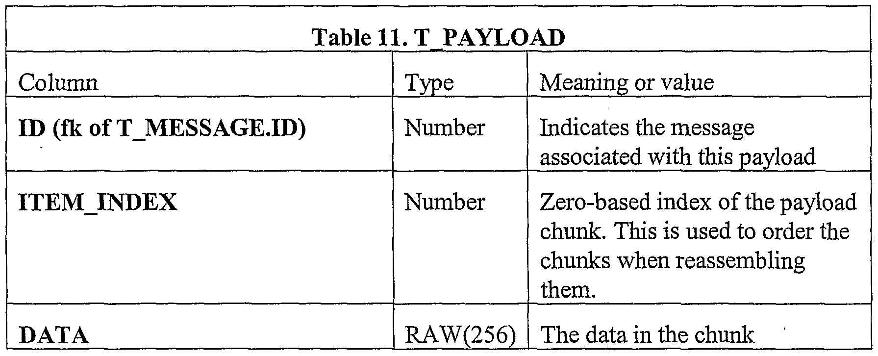
Table 11 , T JPAYLOAD, is a database entry which contains a portion of a message. The router breaks a message into 256 byte chunks in order to optimize use of space when uploading messages. A given message has one TJVTESSAGE row and usually 1-3, but sometimes up to 20 rows in the T PAYLOAD table.
Figure imgf000029_0001
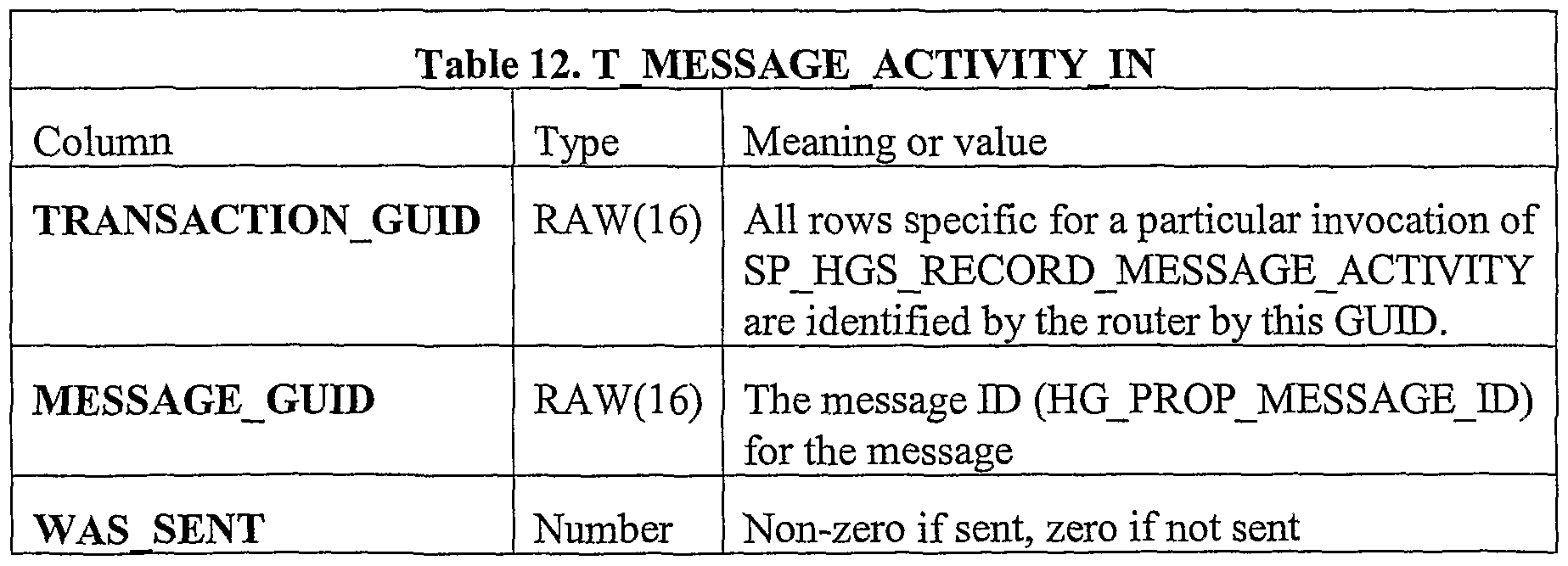
Table 12, T _MESSAGE_ACT-NITY_1N, is used by the router to inform the database of messages sent and not sent. The router creates a transaction GUTD and puts it in each row of T_MESSAGE_ACTTVITY_ΓN, then calls PKG_HGS_MESSAGE.SP_HGS_ RECORD_MESSAGE_ACTIVITY to process the results.
Figure imgf000029_0002
3.2 Router stored procedures
The router's stored procedures are contained in three packages,
• PKG_HGS_ROUTER - for configuring the router and bringing it online.
• PKG_HGS_CONNECTION - for processing device connections to a router.
• PKG_HGS_MESSAGE - for processing messages to a device.
3.2.1 Router online and offline states
PKG__HGS_ROUTER contains the stored procedures that bring a router online, that take the router offline, that reset the watchdog timer, and that find other routers. A generalized router state diagram for these procedures is illustrated in Fig. 5. The states of the router device include an offline state 1500, a running state 1510, and a disconnect scheduled state 1520. The PKG_HGS_ROUTER software package contains these and other stored procedures. For example:
• SP_HGS_TNIT - The router calls this stored procedure when it comes online. The procedure has five purposes: o To create a new entry in T_ROUTER for routers that are connecting for the first time. o To initialize device states (if a network has only one router and the router terminates without calling SP_HGS_EXIT, device connect states may hold the erroneous STATUS_ONLTNE at the time SP_HGS_TNIT is called. o To mark the router as online. o To create new entries in the T_ROUTER_NIC table for new network cards. o To record the current IP addresses of the router's network cards, o To return the configuration information for the router's network cards. A router creates one row in the T_ROUTER_NTCJLN table for each of its network cards. All rows should contain the same transaction GUTD. This GUTD is passed into SP_HGS_TNIT to update its T_ROUTER_NIC table.
The following are the parameters for calls to SPS_HGS_TNIT:
Figure imgf000031_0001
Figure imgf000032_0001
SP_HGS_WATCHDOG - this stored procedure has several different functions: o It records the fact that the router is still active. o It updates the router's load metric and adjusts network card configuration based on this metric, o It takes routers that are inactive (e.g. because they terminated unexpectedly, were isolated from the database, were deadlocked) offline. This also marks all devices assigned to the inactive router as offline, o It transmits the router' s network card configuration, allowing the router to update any changes. The stored procedure has the following parameters:
Figure imgf000033_0001
Note in particular from the above that each router periodically determines a relative load metric and stores this information in the LOAD_METRIC. In the preferred embodiment, a lower number indicates a better performing router. As will be understood shortly, the LOAD_METRIC entry is used by the router to determine how often to send an availability message to the network devices 10.
• SP_HGS_EXIT - this stored procedure is called as its last database communication before terminating. It has the following functions: o It marks the router as offline. o It sets the device connect state of any devices connected to the router as offline. SP_HGS_EXIT has the following parameters:
Parameter List 3. PKG HGS ROUTER.SP HGS EXIT
Parameter Type Meaning or value
ROUTER ID PARAM Number The router going offline (T ROUTER.TD)
SP_HGS_FIND_PATH - this stored procedure finds the possible paths between two routers. It has the following parameters:
Figure imgf000035_0001
Figure imgf000035_0002
3.2.2 Router handling of connection requests
The routers also of course handle connection requests from the network devices 10. A state diagram for this process is shown in Fig. 6. Generally, a state 1600 is an offline state, state 1610 is entered when a connection request is received in the offline state, state 1620 is an online state, state 1630 is an online connection request state, and state 1640 is entered when the router is disconnecting and receives a connection request.
The procedures called to implement these states are now discussed. PKG_HGS_ CONNECTION contains the stored procedures to record connection requests from devices, to inform routers of devices requiring connection and to record the connection state of these devices. PKG_HGS_CONNECTION has the following stored procedures that are called from the C++ router:
• SP_HGS_CONNECT_REQUEST - used by the router to transmit the set of devices issuing connect requests.
• SP_HGS_CONNECTION_ACTrvTTY - used by the router to transmit the set of devices whose connect states has changed.
• SP_HGS_CONNECT - returns the set of devices requiring connection because of connect requests.
• SP_HGS_MSG_CONNECT - returns the set of devices requiring connection because of messages pending.
• SP_HGS_DISCONNECT - returns the set of devices requiring disconnection from stale connections.
PKG_HGS_CONNECTION also contains a stored procedure, SP_HGS_ONE_CONNECT_REQUEST, that maybe called externally by other stored procedures to bring a device online. This may be done to prepare the device to receive messages from a service. SP_HGS_CONNECT_REQUEST - This stored procedure records connection requests from devices. Devices send their IP address and listener port when they have messages to send to a router. The stored procedure records these in the database. The router creates rows in the T_CONNECT_REQUEST_TN table, then calls SP_HGS_CONNECT_REQUEST to process the requests. SP_HGS_CONNECT_REQUEST has the following functions:
• It creates a new row in the T DEVICE table for unassigned devices. SP_HGS_CONNECT_REQUEST will do this for devices which do not transmit a MAC address or device ID (indicating that they don't know either quantity) or that transmit MAC addresses or device Ids that aren't in the T_DENICE table.
• It updates the TP address and port # in each device's T_DENICE row.
• It assigns a router and device GUTD to a device based on router load and the connecting network.
SP_HGS_COΝΝECT_REQUEST has the following parameters:
Figure imgf000037_0001
SP_HGS_CONNECT. The router calls this stored procedure to get the set of devices requiring connection because of connection requests. This includes connection requests from SP_HGS_CONNECT_REQUEST and those due to messages being sent to offline devices. These are cases requiring relatively immediate response. SP_HGS_CONNECT returns a cursor containing the information needed to connect. The procedure has the following parameters:
Figure imgf000038_0001
Figure imgf000038_0002
SP_HGS_MSG_CONNECT - this stored procedure returns the set of connections to be made to devices with messages pending. This call should be made less frequently than SP_HGS_CONNECT (and, if possible, with lower priority) because it is relatively expensive compared to SP_HGS_CONNECT and because the connections do not need to be made in a timely fashion. SP_HGS_MSG_CONNECT has the same parameter signature as SP_HGS_CONNECT.
SP_HGS_DISCONNECT - this stored procedure returns the set of stale device connections. The router should attempt to disconnect from these devices. SP_HGS_DIS CONNECT has the same parameter signature as SP_HGS_CONNECT.
SP_HGS_CONNECT_ACTIVITY - the router updates the connection state in T_DEVICE using this stored procedure. The router inserts rows into T_HGS_CONNECT_ACTIVITY_ΓN. Each row contains a transaction GUTD which correlates the row with the particular invocation of SP_HGS_CONNECT_ACTINITY. SP_HGS_COΝΝECT_ACTIVITY updates T_DEVICE.CONNECT_STATE for each row processed, deletes the row and sends a result code in CURS_ACTTVITY_PARAM which is returned from the stored procedure.
Parameter List 9. PKG HGS CONNECTION.SP HGS CONNECT ACTIVITY
Parameter Type Meaning or value
TRANSACTION ID IN RAW(16) All rows in
T_HGS_CONNECT_ACTTVITY_TN are identified by the router by this GUTD.
CURS ACTIVITY PARAM Cursor The procedure returns one row per row in
T_HGS_CONNECT_ACTIVITY_ΓN to indicate success or failure of the operation.
Figure imgf000040_0001
SP_HGS_ONE_CONNECT_REQUEST - this stored procedure makes a connect request on behalf of some other stored procedure. It operates similarly to SP_HGS_CONNECT_REQUEST (in fact it provides the implementation for SP_HGS_CONNECT_REQUEST in the current, but not subsequent, code base). It has the following parameters:
Figure imgf000041_0001
3.3.3 Router messaging states
Once connections are made, the routers 250 of course also handle the processing of messages. This process is shown generally in Fig. 7, and includes a status not sent state 1700, a status sending state 1710, a status failed sending state 1720, and a status message deleted state 1730.
The stored procedure PKG_HGS_MESSAGE contains the program code that verify incoming messages, that pick messages eligible for transmission, that update message state, and that delete messages. The following messages are intended for external access:
• SP_HGS_PUT_MESSAGES - this procedure verifies the destination address of messages and commits the insert transaction.
• SP_HGS_GET_MES SAGES - this procedure gets a cursor of payloads of messages to be sent from a particular router to connected devices.
• SP_HGS_RECORD_MESSAGE_ACTTVITY - this procedure reports the results of attempts to send the messages retrieved by SP_HGS_GET_MESSAGES
• SP_HGS_DELETE_EXPIRED - this procedure deletes messages that have expired. It should be run from a job within Oracle.
Both SP_HGS_GET_MESSAGES and SPJHGS_RECORD_MESSAGE_ACTIViTY update T_MESSAGE.SEND_STATE. Each of them updates T_MESSAGE.OTD whenever it updates T_MESSAGE.SEND_STATE. This allows each stored procedure to exclude rows modified between selection via cursor and update. SP_HGS_PUT_MESSAGES - the router creates a row in the T JVIESSAGE and multiple rows in the T_PAYLOAD table for each message persisted to the database. It uses a unique OID to mark all of these messages and unique IDs to mark each individual message and its payloads. SP_HGS_PUT_MES SAGES validates the destination device IDs - these are created by C++ applications and may be invalid. It deletes any invalid messages and commits the rest.
Figure imgf000043_0001
SP_HGS_GET_MESSAGES - the router retrieves the set of messages to process via this stored procedure. The stored procedure returns a cursor of payloads; these payloads are ordered by message ID and then by payload item index. SP_HGS_ GET_MESSAGES changes the message state to STATUS_SEND_TN_PROGRESS for outgoing messages to prevent a resend. SP_HGS_GET_MESSAGES has the following parameters:
Parameter List 13. PKG HGS CONNECTION.SP HGS GET MESSAGES
Parameter τype Meaning or value
ROUTER ID PARAM Number Calling router's ID
CURS PAYLOAD REF PARAM Cursor The payloads of the messages to be sent.
Figure imgf000044_0001
SP_HGS_RECORD_MESSAGE_ACTIVITY - this stored procedure records the result of an attempt to send a message retrieved via SP_HGS_GET_MES SAGES. The router inserts rows into T_MESSAGE_ACTΓVITY_IN indicating the results of a transfer attempt. It marks each row in this table with a transaction GUTD which it passes into •
SP_HGS_RECORD_MESSAGE_ACTΓVITY. SP_HGS_RECORD_MESSAGE_ACTΓVITY deletes any messages marked as sent and sets the send state of any unsent messages to STATUS_SEND_FATLED. SP_HGS_RECORD_MESSAGE_ACTIVITY has the following parameters:
Figure imgf000045_0001
4.0 Device connection protocol
Having now some basic appreciation for the various information maintained to effect message routing, the following mechanisms are used to allow network devices to send connection request messages in an attempt to communicate with the data center through the routers 250 in accordance with the invention.
Basically, there are three possible scenarios for a network device attempting to connect to a router, including broadcast requests, DNS (static IP) requests, and multicast type requests.
Broadcast: A device may broadcast its device connection packet in certain limited instances, such as if it is less than one network hop from a router.
DNS or static IP: A device may send a connection packet to a router known to be at a particular DNS or static IP address.
Multicast or broadcast availability: This is the most common case and the one to which the present invention is directed. A router announcer process multicasts or broadcasts a list of routers that can be sent connection requests. The multicast or broadcast takes place on a known TP address and port, using a UDP protocol. The payload portion of such a router announcement service UDP packet is shown in Fig. 8. The packet includes at least an identifier field 500 indicating the type of packet, e.g., that this is a router announcement packet. A field of 128 bits is allocated for the identifier field 500 in this embodiment.
In addition, a time field 510 indicating the time of the announcement, and a port number 520 for establishing a connection to the router, are also included. The time field 510 supports synchronization of events within the entire system as well as security functions. The port number provides the port used to address the packet to the router process. A separate network address for the router need not be specified in the payload portion of the packet, since this information can be gleaned from the UDP header information (not shown in Fig. 7).
The system allows provisioning for more than one router as equally preferred. For instance, if two routers are at a particular location, then they can each send availability messages. Devices would be as likely to receive one packet as the other. The preferred port number of the router announcer is 18505. The preferred port for connection requests on the router is 18503. In response to receiving an announcer message, the network devices can then request that they be permitted to connect to the announcing router. This takes the form of a device connection UDP packet. The packet itself contains enough information to discern at least the requesting device's IP address.
There are three cases for the device connect messages shown respectively in Figs. 9A, 9B, and 9C. hi the first instance, shown in Fig. 9A, the network device does not know its device ID or MAC address. This can be used as an initial provisioning case for devices with inaccessible MAC addresses.
In a second instance, shown in Fig. 9B, the network device knows its MAC address. This is the preferred case as it allows the server to change the device's device ID.
In a third instance, shown in Fig. 9C, the device has cached its device ID from a previous call.
Regardless of the addressing format, the payload portion of the packet data provides the port number and device ID or MAC address for the device, as used by the router in establishing the connection to the requesting network device.
Finally, in response to receipt of one of these messages, a given one of the routers will respond by connecting to the network device 10. The router preferably sends a clock message as the first message to the device. The clock message contains the network device's assigned GUTD in the message header field,. The device can then use this GUTD as its sender identification for subsequent messages. The clock message can contain a device TD different from the one sent in the case where the MAC address is unknown. The device will persist the new device ID and use it in subsequent device connections.
The particular router 250 chosen for response can be coordinated by the queue manager 260 or in other ways, by taking into account the loading factors of the respective routers 250. For example, a relatively lightly loaded router will be selected for handling the new connection, as opposed to a presently busier one. Round robin, least loaded, or any number of other known load balancing schemes can be employed to select among the available routers 250. While this invention has been particularly shown and described with references to preferred embodiments thereof, it will be understood by those skilled in the art that various changes in form and details maybe made therein without departing from the scope of the invention encompassed by the appended claims.

Claims

CLATMSWhat is claimed is:
1. In a network system that connects a central location with a large number of network devices, a method for balancing the coordination of responses to connection requests originating at the network devices comprising the steps of: sending a router availability message through a designated router to a specific network device, the designated router located at the central location; and sending a connection request message from a specific network device to the central location through the router indicated by a received router availability message, and only in response to receiving a router availability message at the specific network device.
2. A method as in claim 1 additionally comprising the steps of: forwarding the connection request message to the central location; and reassigning connection requests from a specific network device to a router under control of the central location, so that connection requests remain distributed among a number of available routers.
3. A method as in claim 1 wherein the router availability message is repeated at a rate which depends upon the relative availability of the router to service the message.
4. A method as in claim 1 wherein the messages are connection request messages originating from a network devices requesting that a connection be made to the central location.
5. A method as in claim 1 wherein the router availability message indicates a network address at which the network device may respond.
6. A method as in claim 1 wherein the router availability message indicates a time window within which the network device may respond.
7. A method as in claim 1 wherein the router availability message is a UDP datagram.
8. A method as in claim 1 wherein the router availability message is sent as a broadcast message.
9. A method as in claim 1 wherein the router availability message is sent as a multicast message to a specific group of network devices.
10. A method as in claim 1 wherein the router availability message represents a right for the network device to connect to the router for a limited time only.
11. A method as in claim 1 wherein subsequent payload messages include network device event logs.
12. A method as in claim 1 wherein the router availability message is sent through multiple designated routers.
PCT/US2001/043136 2000-11-28 2001-11-21 Load balancing in set top cable box environment WO2002044920A1 (en)

Priority Applications (2)

Application Number Priority Date Filing Date Title
CA2430125A CA2430125C (en) 2000-11-28 2001-11-21 Load balancing in set top cable box environment
EP01998903A EP1344144B1 (en) 2000-11-28 2001-11-21 Load balancing in set top cable box environment

Applications Claiming Priority (6)

Application Number Priority Date Filing Date Title
US25344200P 2000-11-28 2000-11-28
US60/253,442 2000-11-28
US09/999,718 US7653743B2 (en) 2000-11-28 2001-10-31 Protocol for throttling high volume messages
US09/999,718 2001-10-31
US10/003,805 2001-11-02
US10/003,805 US7047273B2 (en) 2000-11-28 2001-11-02 Load balancing in set top cable box environment

Publications (1)

Publication Number Publication Date
WO2002044920A1 true WO2002044920A1 (en) 2002-06-06

Family

ID=27357493

Family Applications (1)

Application Number Title Priority Date Filing Date
PCT/US2001/043136 WO2002044920A1 (en) 2000-11-28 2001-11-21 Load balancing in set top cable box environment

Country Status (3)

Country Link
EP (1) EP1344144B1 (en)
CA (1) CA2430125C (en)
WO (1) WO2002044920A1 (en)

Cited By (1)

* Cited by examiner, † Cited by third party
Publication number Priority date Publication date Assignee Title
GB2396444A (en) * 2002-12-18 2004-06-23 Nokia Corp A Method of Announcing Sessions

Citations (10)

* Cited by examiner, † Cited by third party
Publication number Priority date Publication date Assignee Title
US5805804A (en) * 1994-11-21 1998-09-08 Oracle Corporation Method and apparatus for scalable, high bandwidth storage retrieval and transportation of multimedia data on a network
EP0950952A2 (en) 1998-04-14 1999-10-20 International Business Machines Corporation Server workload management in an asynchronous client/server computing system
US5982413A (en) * 1995-05-01 1999-11-09 Fujitsu Limited Mixed analog-digital service distribution system and method
US5991292A (en) * 1997-03-06 1999-11-23 Nortel Networks Corporation Network access in multi-service environment
US6006257A (en) 1995-09-29 1999-12-21 Comverse Networks Systems, Inc. Multimedia architecture for interactive advertising in which secondary programming is varied based upon viewer demographics and content of primary programming
US6055560A (en) 1996-11-08 2000-04-25 International Business Machines Corporation System and method to provide interactivity for a networked video server
US6084876A (en) 1995-09-27 2000-07-04 Microsoft Corporation Dynamic ATM connection management in a hybrid fiber-coax cable network
US6092178A (en) * 1998-09-03 2000-07-18 Sun Microsystems, Inc. System for responding to a resource request
US6111882A (en) * 1996-08-22 2000-08-29 Fujitsu Limited On-demand system
US6195680B1 (en) * 1998-07-23 2001-02-27 International Business Machines Corporation Client-based dynamic switching of streaming servers for fault-tolerance and load balancing

Family Cites Families (3)

* Cited by examiner, † Cited by third party
Publication number Priority date Publication date Assignee Title
US5617540A (en) * 1995-07-31 1997-04-01 At&T System for binding host name of servers and address of available server in cache within client and for clearing cache prior to client establishes connection
US5857190A (en) * 1996-06-27 1999-01-05 Microsoft Corporation Event logging system and method for logging events in a network system
EP1041775A1 (en) * 1999-03-30 2000-10-04 International Business Machines Corporation Router monitoring in a data transmission system utilizing a network dispatcher for a cluster of hosts

Patent Citations (10)

* Cited by examiner, † Cited by third party
Publication number Priority date Publication date Assignee Title
US5805804A (en) * 1994-11-21 1998-09-08 Oracle Corporation Method and apparatus for scalable, high bandwidth storage retrieval and transportation of multimedia data on a network
US5982413A (en) * 1995-05-01 1999-11-09 Fujitsu Limited Mixed analog-digital service distribution system and method
US6084876A (en) 1995-09-27 2000-07-04 Microsoft Corporation Dynamic ATM connection management in a hybrid fiber-coax cable network
US6006257A (en) 1995-09-29 1999-12-21 Comverse Networks Systems, Inc. Multimedia architecture for interactive advertising in which secondary programming is varied based upon viewer demographics and content of primary programming
US6111882A (en) * 1996-08-22 2000-08-29 Fujitsu Limited On-demand system
US6055560A (en) 1996-11-08 2000-04-25 International Business Machines Corporation System and method to provide interactivity for a networked video server
US5991292A (en) * 1997-03-06 1999-11-23 Nortel Networks Corporation Network access in multi-service environment
EP0950952A2 (en) 1998-04-14 1999-10-20 International Business Machines Corporation Server workload management in an asynchronous client/server computing system
US6195680B1 (en) * 1998-07-23 2001-02-27 International Business Machines Corporation Client-based dynamic switching of streaming servers for fault-tolerance and load balancing
US6092178A (en) * 1998-09-03 2000-07-18 Sun Microsystems, Inc. System for responding to a resource request

Non-Patent Citations (1)

* Cited by examiner, † Cited by third party
Title
See also references of EP1344144A4

Cited By (1)

* Cited by examiner, † Cited by third party
Publication number Priority date Publication date Assignee Title
GB2396444A (en) * 2002-12-18 2004-06-23 Nokia Corp A Method of Announcing Sessions

Also Published As

Publication number Publication date
EP1344144A1 (en) 2003-09-17
CA2430125C (en) 2010-04-13
EP1344144B1 (en) 2013-03-13
EP1344144A4 (en) 2009-10-21
CA2430125A1 (en) 2002-06-06

Similar Documents

Publication Publication Date Title
US7916631B2 (en) Load balancing in set top cable box environment
US7653743B2 (en) Protocol for throttling high volume messages
US7216090B2 (en) Promotion packaging for transmission groups
US20020065929A1 (en) Protocol extensions to increase reliability of bulk data transmissions
US20020077909A1 (en) Precasting promotions in a multimedia network
KR100702827B1 (en) System for providing continuity of a broadcast between clients and method therefor
JP2515075B2 (en) Local area network for digital data processing system
US20010047401A1 (en) System and method for managing connections to servers delivering multimedia content
US7328231B2 (en) Generating schedules for synchronizing bulk data transfers to end node devices in a multimedia network
EP1047005A1 (en) Method for distributing information
US20020013897A1 (en) System and method for secure delivery of rich media
EP1346571B1 (en) Synchronization of bulk data transfers to end node devices in a multimedia network
EP1320994A4 (en) Systems and method for interacting with users over a communications network
IL173011A (en) Image insertion for cellular text messaging
US20030212739A1 (en) Store and forward architecture
EP1464163B1 (en) Module and process for use with inter-user communication via a bidirectional network
US20080065725A1 (en) Notification of internet service events using instant messaging service
CA2430125C (en) Load balancing in set top cable box environment
EP1936876B1 (en) Method and system for ensuring data exchange between a server system and a client system
US20010011305A1 (en) File transmission acknowledgement system and method
EP1983725B1 (en) Information delivery system and information delivery method using the same

Legal Events

Date Code Title Description
AK Designated states

Kind code of ref document: A1

Designated state(s): CA JP MX

AL Designated countries for regional patents

Kind code of ref document: A1

Designated state(s): AT BE CH CY DE DK ES FI FR GB GR IE IT LU MC NL PT SE TR

121 Ep: the epo has been informed by wipo that ep was designated in this application
WWE Wipo information: entry into national phase

Ref document number: 2430125

Country of ref document: CA

WWE Wipo information: entry into national phase

Ref document number: 2001998903

Country of ref document: EP

WWP Wipo information: published in national office

Ref document number: 2001998903

Country of ref document: EP

NENP Non-entry into the national phase

Ref country code: JP

WWW Wipo information: withdrawn in national office

Country of ref document: JP