WO2001061912A1 - Packet processor - Google Patents

Packet processor Download PDF

Info

Publication number
WO2001061912A1
WO2001061912A1 PCT/US2001/004599 US0104599W WO0161912A1 WO 2001061912 A1 WO2001061912 A1 WO 2001061912A1 US 0104599 W US0104599 W US 0104599W WO 0161912 A1 WO0161912 A1 WO 0161912A1
Authority
WO
WIPO (PCT)
Prior art keywords
data
authentication
data packet
packet
encryption
Prior art date
Application number
PCT/US2001/004599
Other languages
French (fr)
Inventor
Dung Le Huynh
Roger J. Brouwer
Original Assignee
Rainbow Technologies, Inc.
Priority date (The priority date is an assumption and is not a legal conclusion. Google has not performed a legal analysis and makes no representation as to the accuracy of the date listed.)
Filing date
Publication date
Application filed by Rainbow Technologies, Inc. filed Critical Rainbow Technologies, Inc.
Priority to AU2001236970A priority Critical patent/AU2001236970A1/en
Publication of WO2001061912A1 publication Critical patent/WO2001061912A1/en

Links

Classifications

    • HELECTRICITY
    • H04ELECTRIC COMMUNICATION TECHNIQUE
    • H04LTRANSMISSION OF DIGITAL INFORMATION, e.g. TELEGRAPHIC COMMUNICATION
    • H04L63/00Network architectures or network communication protocols for network security
    • H04L63/04Network architectures or network communication protocols for network security for providing a confidential data exchange among entities communicating through data packet networks
    • H04L63/0428Network architectures or network communication protocols for network security for providing a confidential data exchange among entities communicating through data packet networks wherein the data content is protected, e.g. by encrypting or encapsulating the payload
    • H04L63/0442Network architectures or network communication protocols for network security for providing a confidential data exchange among entities communicating through data packet networks wherein the data content is protected, e.g. by encrypting or encapsulating the payload wherein the sending and receiving network entities apply asymmetric encryption, i.e. different keys for encryption and decryption
    • HELECTRICITY
    • H04ELECTRIC COMMUNICATION TECHNIQUE
    • H04LTRANSMISSION OF DIGITAL INFORMATION, e.g. TELEGRAPHIC COMMUNICATION
    • H04L63/00Network architectures or network communication protocols for network security
    • H04L63/04Network architectures or network communication protocols for network security for providing a confidential data exchange among entities communicating through data packet networks
    • H04L63/0428Network architectures or network communication protocols for network security for providing a confidential data exchange among entities communicating through data packet networks wherein the data content is protected, e.g. by encrypting or encapsulating the payload
    • H04L63/0485Networking architectures for enhanced packet encryption processing, e.g. offloading of IPsec packet processing or efficient security association look-up
    • HELECTRICITY
    • H04ELECTRIC COMMUNICATION TECHNIQUE
    • H04LTRANSMISSION OF DIGITAL INFORMATION, e.g. TELEGRAPHIC COMMUNICATION
    • H04L63/00Network architectures or network communication protocols for network security
    • H04L63/08Network architectures or network communication protocols for network security for authentication of entities
    • H04L63/0823Network architectures or network communication protocols for network security for authentication of entities using certificates
    • HELECTRICITY
    • H04ELECTRIC COMMUNICATION TECHNIQUE
    • H04LTRANSMISSION OF DIGITAL INFORMATION, e.g. TELEGRAPHIC COMMUNICATION
    • H04L63/00Network architectures or network communication protocols for network security
    • H04L63/12Applying verification of the received information
    • H04L63/123Applying verification of the received information received data contents, e.g. message integrity
    • HELECTRICITY
    • H04ELECTRIC COMMUNICATION TECHNIQUE
    • H04LTRANSMISSION OF DIGITAL INFORMATION, e.g. TELEGRAPHIC COMMUNICATION
    • H04L9/00Cryptographic mechanisms or cryptographic arrangements for secret or secure communications; Network security protocols
    • H04L9/06Cryptographic mechanisms or cryptographic arrangements for secret or secure communications; Network security protocols the encryption apparatus using shift registers or memories for block-wise or stream coding, e.g. DES systems or RC4; Hash functions; Pseudorandom sequence generators
    • H04L9/0643Hash functions, e.g. MD5, SHA, HMAC or f9 MAC
    • HELECTRICITY
    • H04ELECTRIC COMMUNICATION TECHNIQUE
    • H04LTRANSMISSION OF DIGITAL INFORMATION, e.g. TELEGRAPHIC COMMUNICATION
    • H04L2209/00Additional information or applications relating to cryptographic mechanisms or cryptographic arrangements for secret or secure communication H04L9/00
    • H04L2209/04Masking or blinding
    • HELECTRICITY
    • H04ELECTRIC COMMUNICATION TECHNIQUE
    • H04LTRANSMISSION OF DIGITAL INFORMATION, e.g. TELEGRAPHIC COMMUNICATION
    • H04L2209/00Additional information or applications relating to cryptographic mechanisms or cryptographic arrangements for secret or secure communication H04L9/00
    • H04L2209/12Details relating to cryptographic hardware or logic circuitry
    • H04L2209/125Parallelization or pipelining, e.g. for accelerating processing of cryptographic operations
    • HELECTRICITY
    • H04ELECTRIC COMMUNICATION TECHNIQUE
    • H04LTRANSMISSION OF DIGITAL INFORMATION, e.g. TELEGRAPHIC COMMUNICATION
    • H04L63/00Network architectures or network communication protocols for network security
    • H04L63/16Implementing security features at a particular protocol layer
    • H04L63/164Implementing security features at a particular protocol layer at the network layer
    • HELECTRICITY
    • H04ELECTRIC COMMUNICATION TECHNIQUE
    • H04LTRANSMISSION OF DIGITAL INFORMATION, e.g. TELEGRAPHIC COMMUNICATION
    • H04L9/00Cryptographic mechanisms or cryptographic arrangements for secret or secure communications; Network security protocols
    • H04L9/50Cryptographic mechanisms or cryptographic arrangements for secret or secure communications; Network security protocols using hash chains, e.g. blockchains or hash trees

Definitions

  • This invention relates in general to computer-implemented systems for processing packets, and, in particular, to performing encryption and authentication in parallel while processing packets.
  • Cryptography involves transforming data into an unreadable format that can be deciphered with a "key” and transformed into a readable format. Cryptography may be used to protect various types of information, such as e-mail messages and personal information (e.g., bank account numbers).
  • authentication involves determining whether the source of particular data is a valid source. Authentication may involve using passwords or user names. This information may be appended to the data being transmitted so that the receiving computer can authenticate the data as coming from an appropriate transmitting computer.
  • cryptographic units or modules have been developed for providing encryption and/or decryption functions.
  • various forms of authentication units or modules have been developed for providing authentication functions.
  • a combination of cryptographic and authentication units may be used, for example, to append authentication information to data before or after encryption. This authenticated and encrypted data may then be transmitted from a first computer to a second computer. The second computer uses the authentication information to determine whether the source of the data is a valid source, and also decrypts the data for processing.
  • each packet must be encrypted and authenticated before the next packet is encrypted and authenticated. This continues until each packet is processed.
  • One problem with this technique is that each packet to be encrypted must wait until the previous packet was both encrypted and authenticated.
  • the second packet need only wait until the required individual resource (rather than the combined encryption/authentication unit) becomes available. For instance, the second packet need only wait until the first packet has been encrypted and passed to the authentication unit. Once the first packet is passed to the authentication unit, the second packet may be provided to the encryption unit and encryption of the second packet may begin while authentication of the first packet proceeds. Thus, the system need not wait until the first packet is completely encrypted and authenticated before beginning encryption of the second package.
  • independent encryption and authentication units can result in significantly more communication traffic and congestion on the internal or external communication buses, as data is transferred between memory and each of the independent units. Such congestion can increase processing latency and reduce throughput. The congestion problem increases as the number of authentication units and encryption units increases.
  • the present invention discloses a method, apparatus, and article of manufacture for a computer-implemented packet processor.
  • a packet processor comprises one encryption unit and two authentication units arranged and controlled such that a packet may be encrypted and authenticated (once or twice) in a single pass through the packet processor.
  • the packet processor is controlled to begin processing a second packet as soon as the required encryption or authentication unit becomes available, while other units may still be processing the first packet.
  • performance is improved even more by using the two authentication units to perform one authentication (for HMAC- key hashing).
  • FIG. 1 is an exemplary packet processor and system according to an embodiment of the invention
  • FIG. 2 is an exemplary packet processor and system according to another embodiment of the invention.
  • FIG. 3 is an exemplary packet processor and system according to a preferred embodiment of the invention
  • FIG. 4 is a timing chart, illustrating the timing of the processing of multiple packets
  • FIG. 5 is a preferred example configuration of the packet processor and system of Fig. 3;
  • FIG. 6 is a block diagram illustrating a packet and a mask
  • FIG. 7 is a block diagram illustrating outbound packet processing
  • FIG. 8 is a block diagram illustrating inbound packet processing. DETAILED DESCRIPTION OF THE PREFERRED EMBODIMENT
  • FIG. 8 is a block diagram illustrating inbound packet processing.
  • One embodiment of the present invention provides a packet processor for processing packets of data.
  • the packet processor encrypts data and/or decrypts encrypted data and provides at least one, and preferably multiple levels of authentication.
  • encryption (or decryption) and authentication are implemented in separate units, such that one or more resources (encryption, decryption or authentication units) may become available to process a data packet, while one or more other resources are processing another data packet.
  • a data bus configuration is employed for minimizing communication traffic congestion problems, as data is transferred to and from the separate encryption, decryption and authentication units.
  • a packet processor 204 comprises a control unit 106, one crypto unit 108 and two authentication units 110 and 112, arranged and controlled such that a packet may be encrypted and authenticated (once or twice) in a single pass through the packet processor.
  • the control unit 106 comprises a RAM-based controller.
  • the control unit may be implemented using any suitable programmable processor or other the like.
  • the cryptography component 108 may comprise, for example, a "crypto core” having a data encryption standard (DES), which is a symmetric-key encryption technique. With a symmetric-key technique, the sender and receiver of a message share a single key.
  • the cryptography component 108 may use other encryption standards, including, but not limited to, 3DES and RC4. Further embodiments may employ other suitable cryptographic devices and encryption standards, for encrypting and/or decrypting data.
  • the authentication units 1 10 and 112 may comprise any suitable authentication devices, including, but not limited to "HMAC cores" (e.g., HMAC-SHA-1 or HMAC-MD5), which use standard authentication hashing techniques.
  • HMAC cores e.g., HMAC-SHA-1 or HMAC-MD5
  • the packet processor 104 is coupled to a computer or main processor 100, through a processor bus 102.
  • the computer or main processor 100 may comprise any suitable computer or data processing device, including, but not limited to a personal computer PC, PowerPC (PPC), mainf ame, or the like, which may include, inter alia, a processor device and random access memory (RAM), and may be coupled to one or more data storage devices (e.g., hard, floppy, and/or CD-ROM disk drives, etc.), data communications devices (e.g., modems, network interfaces, etc.), a monitor (e.g., CRT, LCD display, etc.), a mouse pointing device, and/or a keyboard.
  • An example memory device 101 is shown in Fig.
  • the computer 100 may be connected to other devices such as read only memory (ROM), a video card, bus interface, printers, etc., through the processor bus 102.
  • ROM read only memory
  • video card a video card
  • bus interface a bus interface
  • printers etc.
  • any combination of the above components, or other components, peripherals, and devices, may be used with the computer 100.
  • the controller 106 and the crypto and authentication units 108, 110, and 112 are each coupled to the processor bus 102 by a respective link and are each capable of being a bus master, to take over the processor bus 102 and perform its own read or write transfers. These devices may also act as slave devices and may be accessed by the computer 100, through the processor bus 102. Because the crypto unit 108 and the authentication units 110 and 112 each use a separate bus interface or link to the processor bus 102, each of those units may be used independently of the other units.
  • the packet processor of Fig. 1 may be configured to provide a single cryptographic function (encryption and/or decryption), by activating only the crypto unit 108. Alternatively, the packet processor of Fig.
  • Fig. 1 may be configured to provide a single cryptographic function and a single authentication function, by activating the crypto unit 108 and one of the authentication units, such as unit 110.
  • the packet processor of Fig. 1 may be configured to provide a cryptographic function and two authentication functions, by activating the crypto unit 108 and both of the authentication units 110 and 112.
  • One skilled in the art will recognize that other variations of the Fig. 1 embodiment may employ other combinations of one or more cryptographic units and one or more authentication units, each of which are coupled to a processor bus for read or write transfer operations independent of the other cryptographic or authentication units.
  • Fig. 1 information to be processed by the packet processor 104 is provided to each of the units 108, 110 and/or 112 over the bus 102, as described below.
  • Fig. 1 may represent an embodiment example, wherein information is provided in the form of one or more packets, for encryption and appending of one or more authorization codes.
  • the processor 100 reads packets of information from the processor bus 102 and operates to process the packets to identify data fields to be encrypted.
  • Information to be encrypted is stored in a memory device, such as memory 101, for example, under the control of the processor 100.
  • the crypto unit 108 If the crypto unit 108 is available (not presently encrypting information from another packet), the information to be encrypted is read into the crypto unit 108, over the processor bus 102, from the memory device, such as memory 101.
  • the crypto unit 108 operates to encrypt the information and write the information into a memory device, such as memory 101, over the processor bus 102. Thereafter, the crypto unit 108 is available to encrypt information from another packet.
  • the crypto unit 108 may begin processing the information from a second packet, without the need to wait for the encrypted information from the first packet to be processed by the authentication units 110 and 112.
  • the encrypted information written into the memory device is read into a first one of the authentication units 110, which generates an authentication code for the information and writes the authentication code into a memory device, such as memory 101. Thereafter, the authentication unit 110 is available to authenticate information from another packet. Thus, the authentication unit 110 may begin processing the information from a second packet, without the need to wait for the information from the first packet to be processed by the authentication unit 112.
  • the encrypted information and appended authentication code may be read into the second authentication unit 112 over the processor bus 102, from a memory device, such as memory 101.
  • the second authentication unit 112 generates a second authentication code for the information and writes the resulting authentication codes into a memory device, such as memory 101, over the processor bus 102.
  • the processor 100 may then access the stored information and authentication codes and form a resulting packet composed of encrypted information and two levels of authentication codes.
  • the resulting packet may then be communicated from the processor 100, over the processor bus 102 to a load, user, host or the like, or may be stored in a memory device, such as memory 101, for later use.
  • the packet processor shown in Fig. 1 may also represent a decryption embodiment example, wherein information is provided in the form of one or more packets, for decryption and verification of authentication codes.
  • the processor 100 reads packets of information from the processor bus 102 and operates to process the packets to identify data fields to be authenticated and decrypted.
  • Information to be authenticated is stored in a memory device, such as memory 101, for example, under the control of the processor 100. If the authentication unit 112 is available (not presently verifying the authenticity of information from another packet), the information to be authenticated is read into the authentication unit 112, over the processor bus 102, from the memory device, such as memory 101.
  • the authentication unit 112 operates to verify the authenticity of the information in accordance with well known authentication techniques, to provide first authenticated information.
  • the first authenticated information is communicated over the processor bus 102 and stored in a memory device, such as memory 101. Thereafter, the authentication unit 112 is available to authenticate information from another packet.
  • the information to be authenticated is also read from the memory device into the authentication unit 110, which verifies the authenticity of the information in accordance with well known authentication techniques, to provide second authenticated information.
  • the second authenticated information is communicated over the processor bus 102 and stored in a memory device, such as memory 101. Thereafter, the authentication unit 110 is available to authenticate information from another packet.
  • the information in the packet to be decrypted may be read into the crypto unit 108 over the processor bus 102, from a memory device, such as memory 101.
  • the crypto unit 108 decrypts the cipher text from the packet and writes the resulting decrypted information into a memory device, such as memory 101, over the processor bus 102.
  • the processor 100 may then access the stored information and may then communicate the decrypted, authenticated, packet information from the processor 100, over the processor bus 102, to a load, user, host or the like, or may store the information in a further memory device for later use.
  • other processing orders may be implemented, since there is no data-dependency in the data to be processed by each unit.
  • the crypto unit 108 is capable of providing both encryption and decryption functions and is controlled by the processor 100 to provide one of those two functions for a given packet.
  • each authentication unit 110 and 112 is capable of generating authentication code for appending and authentication verification functions and is controlled by the processor 100.
  • each of the processing units (crytpo unit 108 and the two authentication units 110 and 112) are individually coupled to the processor bus 102 by a respective link and are each capable of being a bus master, to take over the processor bus 102 and perform read or write transfers, the processor 1 10 can be controlled to process information from multiple packets at the same time. For example, once the crypto unit 108 completes an encryption process on information from a first packet and writes encrypted data into a memory device, such as memory 101, for further processing by the other processing units, the crypto unit is free to read in and encrypt information from a second packet. While the crypto unit 108 operates on the second packet information, the authentication unit 110 and/or 112 may be operating on the information from the first packet.
  • each processing unit is individually coupled to the processor bus 102 for read and write operations, allows the packet processor to process multiple packets simultaneously and allows processing of the next packet to begin as the resources (such as the crypto unit 108 in the above example) become available, rather than requiring the cryptographic and authentication processing of the first packet to be completed before beginning the processing of a second packet.
  • the independent coupling each processing unit 108, 110 and 112 to the processor bus 102 and the multiple read and write operations that are required over the processor bus to process a packet can result in a relatively large number of communications over the processor bus and, thus, a high level of communication traffic.
  • the processor 106 may be programmed to perform some or all of the functions performed by processor 100 noted above.
  • a packet processor 204 according to a further embodiment of the present invention is shown in Fig. 2 and is configured to address the above-discussed communication traffic problem.
  • the illustration in Fig. 2 shows a processor 100, memory device 101, and processor bus 102, similar to the corresponding devices described above with respect to Fig. 1.
  • the packet processor 204 in Fig. 2 includes a control unit 106, a crypto unit 108 and two authentication units 110 and 112, similar to correspondingly numbered elements discussed above with respect to Fig. 1.
  • further versions of the packet processor 204 may include any suitable combination of one or more crypto units and one or more authentication units.
  • the packet processor shown in Fig. 2 includes a local bus 202.
  • the control unit 106, the crypto unit 108 and the two authentication units 110 and 112 are each coupled to the local bus 202, with the control unit 106 being the only master on the local bus 202.
  • the controller and all processing units in the chain are each coupled to the processor bus 102, with the control unit 106 capable of performing reading and writing operations on the bus 102, while processing units 108, 110 and 112 can only perform write operations on bus 102.
  • the crypto unit 108, authentication unit 110 and authentication unit 112 are coupled for communication in a daisy-chain arrangement, as represented by the daisy-chain connection 206.
  • only the control unit 106 is coupled to the processor bus 102 for both read and write operations.
  • the processing units in the chain are each coupled to receive control instructions and/or data from the control unit 106, over the local bus 202, as discussed below.
  • the control unit 106 uses its busmaster interface to read in the processing parameters and input packet data.
  • the control unit 106 passes processing parameters to the crypto unit 108, the authentication unit 110 and/or the authentication unit 112, over the local bus 202. In this manner, the processing units are set up and ready to accept and process data as it arrives.
  • the authentication units are capable of buffering instructions, parameters and data for the next packet, while processing an earlier packet.
  • the control unit 106 passes the input packet data on to the crypto unit 108, the authentication unit 1 10 and/or the authentication unit 112, over the local bus 202, in the appropriate order.
  • the cipher text output from the crypto unit 108 is transferred to the authentication units 110 and 112 for authentication via the daisy chain bus.
  • the authentication value provided by the authentication unit 110 is made available to the authentication unit 112 for security packets requiring two authentications.
  • the input packet may be read once into the packet processor 204, and up to three cryptographic operations may be performed on the packet.
  • the resulting output packet is written out to the destination, over the processor bus 102, by the processing units (108, 110 and 112), as output data is generated.
  • the control unit 106 reads in packet data and passes data to the applicable unit, as follows. For outbound packets, the control unit 106 passes packet data to crypto unit 108, over the local bus 202. The crypto unit 108 encrypts the data and writes out the encrypted data to the memory device 101. The crypto unit 108 may also pass encrypted data to the authentication units 110 and 112 over the daisy chain connection 206. Authentication unit 110 processes the data and writes out authentication code to the memory device 101. Authentication unit 110 may also pass the authentication code to authentication unit 112 to be processed. Authentication unit 112 processes the data that it receives from processing units 108 and 110, via the daisy chain connection 206, and writes out an authentication code to the memory device 101.
  • the control unit 106 For inbound packets, the control unit 106 passes packet data to crypto unit 108, authentication unit 110 and authentication unit 112, over the local bus 202.
  • the crypto unit 108 decrypts the data and writes decrypted data out to the memory device 101.
  • Authentication unit 110 verifies the authentication code and sets a status bit based on the verification results.
  • Authentication unit 112 verifies a further authentication code and sets a status bit based on the verification results.
  • the control unit 106 collects the authentication verification status bits and writes status information to the memory device 101, over the processor bus 102.
  • the bus architecture of Fig. 2 allows the ability to process multiple packets simultaneously and to use resources (for example, crypto and authentication units) as such resources become available, rather than waiting until each packet is fully processed before starting the processing of the next packet.
  • resources for example, crypto and authentication units
  • the use of the local bus 202 and daisy chain bus 206 allows the control unit 106 and processing units 108, 110 and 112 in Fig. 2 to pass information therebetween, without using the processor bus 102.
  • the crypto unit 108 and the authentication units 110 and 112 do not use the processor bus 102 for reading input data and because intermediate data is not passed between those units over the bus 102, traffic on the processor bus 102 can be reduced or minimized.
  • the processing units are coupled to the processor bus 102 only for communication of the fully processed packet information, the communication traffic demand is minimized, relative to the Fig. 1 embodiment.
  • Fig. 2 Similar to the Fig. 1 embodiment, another advantage of the illustrated architecture in Fig. 2 is that authentication processing may be expedited, even when only one authentication is required. More particularly, the secret key authentication algorithm, for example HMAC, may be split into two processes, including an inner hashing and an outer hashing process. The inner hashing is processed in the first authentication unit 110, the result of which is passed to the second authentication unit 112, for example, over the daisy chain bus 206, to perform the outer hash. This frees the first authentication unit 110 to begin processing the next packet.
  • HMAC secret key authentication algorithm
  • a packet processor 304 according to a preferred embodiment of the present invention is shown in Fig. 3 and includes aspects of both of the embodiments discussed above and shown in Figs. 1 and 2.
  • the packet processor 304 in Fig. 3 includes a control unit 106, a crypto unit 108 and two authentication units 110 and 112, similar to the packet processor shown in Figs. 1 and 2.
  • further versions of the packet processor 304 may include any suitable combination of one or more crypto units and one or more authentication units.
  • the packet processor 304 in Fig. 3 includes individual connections between each of the processing units (crypto unit 108, authentication units 110 and 112) and the processor bus 102, similar to the embodiment shown in Fig. 1, and a local bus 202 and daisy chain connection 206, similar to the embodiment shown in Fig. 2.
  • the embodiment of Fig. 3 may operate in accordance with the above-discussed operation of the packet processor 104 in Fig. 1 or the operation of the packet processor 204 in Fig. 2.
  • the bus architecture described above allows for improved throughput and reduced traffic over the shared processor bus 102. When multiple cryptographic processing is required, data is passed from one unit to another in a somewhat pipelined manner. This implies that one unit may become available before the other units become available.
  • the packet processor (104, 204 or 304) may start processing the next packet as soon as the required resources become available.
  • Fig. 4 shows an example timing schedule for processing four packets, back-to-back, where all packets require the use of all three processing units.
  • the first and third packets are outbound, while the second and fourth packets are inbound.
  • the authentication units 110 and 112 receive the cipher text from the crypto unit 108 and, thus, finish processing the packet after the crypto unit 108 has completed its operation.
  • inbound packets already contain cipher text and, thus, the authentication units do not need to wait for data from the crypto unit 108.
  • the second, third and fourth packets are started as soon as the crypto unit 106 finishes processing the previous packet.
  • the control unit 106 passes parameters from the packet control structures to the cryptography 108 and authentication 110 and 112 components via the packet processor local bus 126.
  • the packet control structures indicate the particular techniques and parameters to be used to encrypt and authenticate a packet.
  • the cryptography component 108 encrypts data received in a First-In-First-Out input queue (InFIFO) 128 and passes encrypted data to the authentication components 110 and 112 and to the First-In-First-Out output queue
  • InFIFO First-In-First-Out input queue
  • OutFIFO 130 to be written out to a destination such as the memory 101, over the bus 102. That is, the cryptography component 108 passes data to the InFIFO queue 132 of authentication component 110 and to the InFIFO queue 134 of the authentication component 112 via the daisy chain bus 136. In this manner the authentication components 110 and 112 receive the encrypted data for authentication.
  • the status unit 114 contains status information about whether the encryption and authentication processes completed successfully.
  • the status unit 114 reports the status of the authentication value comparison along with the status of whether the decryption and authentication were processed successfully.
  • FIG. 5 is not intended to limit the invention. Indeed, those skilled in the art will recognize that other alternative hardware environments may be used without departing from the scope of the invention.
  • IP Internet Protocol
  • IP security refers to a set of protocols being developed by the Internet Engineering Task Force, which is a standards organization for the Internet.
  • the IP security protocols support transport encryption mode, in which only the data portion of each packet is encrypted, and tunnel encryption mode, which encrypts both the header and the data portion of each packet.
  • the packet processor 404 supports the Encapsulating Security Payload ESP and Authentication Header AH protocols as specified for IP security. Specifically, the following transformations are supported for AH protocols:
  • the packet processor 404 could use any of these techniques or some combination of them.
  • the HI core 110 may use HMAC-SHA-1, while the H2 core 112 may use HMAC-MD5.
  • HMAC-SHA-1 the HMAC-SHA-1
  • HMAC-MD5 the HMAC-MD5.
  • the packet processor 404 will also support RC4, SHA- 1 , HMAC-SHA- 1 ,
  • the RAM-based control unit 106 has a small instruction set and a number of dedicated registers. Each instruction performs an operation or a group of operations. These instructions are used to form service routines to process data according to the desired protocol.
  • the general purpose processor 100 such as a PowerPC (PPC), writes these routines to the Instruction RAM 116 via the processor local bus 102 slave interface of the control unit 106.
  • PPC PowerPC
  • a control structure For each packet to be processed, a control structure is required to describe the packet (such as offsets and sizes), to pass parameters, and specify the cryptographic function to be performed. This can be done by the processor 100 or a host computer. The location of the packet control structure, packet data, and packet processing results are required for each packet to be processed.
  • the Cmd FIFO (i.e., command "First in first out” queue) 118 provides a queue for storing pointers to control structures. For the packet processor 404, all data are aligned on a 32-bit word boundary.
  • the packet processor 404 processes commands from the command FIFO 118 according to the mode selected in the command register. For each packet, the packet processor 404 retrieves the instruction RAM 116 offset and packet control structure location from the command FIFO 118 and starts executing the instructions beginning from the specified offset.
  • Data is first transferred into the control unit InFIFO 122 via the processor local bus 102 master read interface of the control unit 106. Data is processed as it becomes available in the InFIFO 122.
  • the OutFIFO 124 is used to queue data that is to be copied to the destination memory 101, such as IP headers.
  • the Mask RAM 120 is preferably programmed with a mask pattern for masking out mutable fields in the header of the packet.
  • the Mask RAM in the illustrated embodiment is 8 bits deep and 32 bits wide. Each bit is used to mask out one byte of data, and is applied to data beginning from the first byte in the packet. Thus, with the 8x32 Mask RAM, the first 256 bytes of the packet data may be masked out.
  • the Mask RAM stores mask data for packet data that is in big endian format. If the packet data is in little endian format, then the control unit 106 swaps the bits.
  • FIG. 6 illustrates the format of the first 32-bit word 600 of the mask pattern.
  • the leftmost nibble (bits 31-28) is to be applied to the first 32-bit word of the packet data, while the next nibble (bits 27-24) is to be applied to the next 32-bit word of the packet data, and so on.
  • FIG. 6 also shows the mapping of the four bits of the leftmost nibble 604 to the first four bytes of the packet data.
  • a mask bit of "1" indicates that the data byte is to be masked to all zeroes.
  • a mask bit of "0" indicates that the data byte is not to be masked.
  • FIG. 7 is a block diagram illustrating outbound packet processing.
  • a packet 700 initially comprises an IP header 702, an AH portion 704, an ESP header 706 and a payload (i.e., data) 708.
  • the payload 708 is encrypted with the cryptography core 108.
  • the HI core 110 authenticates the encrypted payload 708 by adding an ESP authentication 710.
  • the H2 core 112 authenticates the encrypted packet 700 and the ESP authentication 710 by adding another authentication code (i.e., H2 result) 712.
  • FIG. 8 is a block diagram illustrating inbound packet processing.
  • a packet 800 is received.
  • the authentication added by the H2 core 112 is placed by the transmitting host into the AH portion 805 before processing the packet.
  • the packet processor 404 Upon receiving the packet 800, the packet processor 404 performs authentication and compares the results against the ESP authentication 810 and the AH authentication information 805.
  • the packet processor 404 also decrypts the encrypted data 808.
  • the packet processor 404 may be programmed to perform authentication verification first, and then perform decryption only if the authentication is valid, in preferred embodiments the packet processor 404 is programmed to perform authentication and decryption at the same time to minimize overall processing time and significantly improve throughput.
  • Table A indicates a representative example of the packet processor's 404 registers and memories. All offset and size registers are 16-bit wide and indicate the number of bytes. However, the packet processor 404 ignores the two least significant bits since everything has to be on a 32-bit boundary. All offset registers increment while executing the Write data instruction.
  • the Source Address Register specifies the source address.
  • CU Mask RAM, Base Address Register, Destination Address Register, Status Destination Address Register, Packet Command Register, Offset registers (0-7), and Size Registers (0-3).
  • Cores All registers in the Crypto, HI, and H2 cores. Need to execute the Wait instruction to make sure the cores are ready to accept data.
  • Storing size to Size Register 2 also cause (i) HI end offset to be computed and stored in Offset Register 6 and (ii) HI destination address to be computed and stored in HI Destination Address Register.
  • This instruction can also be used to load commands (based on the information provided in the Configuration Register, Command Register, Packet Command FIFO Format
  • the Command FIFO format is 8 bits deep and 41 -bit wide. The following is the format:
  • Bits [40:32] specify the instruction RAM offset. This field is updated by writing to PLB address 0x040 with the offset on bits [8:0] of the data bus. This field is stored in a 9-bit register and is entered into the Command FIFO when the packet control structure address is updated. Bits [31 :01] specify the packet control structure address. Writing to PLB address 0x041 causes the entire 41 bits to be loaded into the Command FIFO.
  • Table D provides a representative example of instructions used in outbound packet processing:
  • Tables E, F, and G provide representative examples of registers in the control unit.
  • the Crypto block 108 performs RC4, DES and 3DES encryption techniques. Input text is either read in by the PLB Master read interface or provided by the packet processor control unit 106.
  • the Crypto block begins execution following the writing to the Command/Status Register. The completion of processing is indicated by the transition of the Busy bit in the Command/Status Register from a one to a zero.
  • the PLB Address for the Crypto Configuration Register is: 0x000200, and this register can be updated at any time.
  • Table J provides a representative example of information about the crypto configuration register:
  • the PLB Address of the Key Length Register is: 0x000204.
  • This 6-bit register contains the key length in number of bytes. Maximum key length is 32 bytes. READ and WRITE are not allowed while RC4 Init Busy is high.
  • the PLB Addresses of the Key Registers are: 0000208, 0x00020C, 0000210, 0000214, 0000218, 000021C, 0000220, 0x000224. These 8 32-bit registers store the key.
  • the register at PLB address 0x208 holds the most significant word, with the leftmost character of the key in the 31 :24 bit position.
  • Key 2 [63:0] is stored in registers at PLB address [0000210 0000214].
  • Key 3 [63:0] is stored in registers at PLB address (0000218
  • Each 64-bit key is loaded into the DES/3DES engine the same clock cycle when a write to the later address (000020C, 0000214, 0x00021C) is performed. Moreover, READ and WRITE operations are not allowed while RC4 Init Busy is high.
  • the PLB Addresses for the DES TV Registers are: 0000228, 0x0022C. These 2 32-bit registers store the initialization vector for DES/3DES CBC mode.
  • the register at PLB address 0x00228 holds the most significant 32-bit word, with the leftmost character of the vector in the 31:24 bit position. WRITE operations are not allowed while Busy is high.
  • the PLB Address of the Source Address Register is: 0x000230. This 32-bit source address register points to the location where the input data to the crypto block will be read.
  • the PLB Address of the Destination Address Register is: 0x000234. This 32-bit destination address register points to the location where the output data from the hash block will be written.
  • the PLB Address for the Crypto Command Status Register is : 0x000238. Writing to this register starts the Crypto block processing. Writing to this register is inhibited while the busy bit is set.
  • a representative example of this register is defined in Table K, which the "crypto" command/status register information.
  • the PLB Address for the FIFO is: 0x100000 - OxlFFFFF.
  • the InFIFO and OutFIFO may be accessed using an address in the above address range.
  • the Endian bit in the Command/Status register must be written to indicate the byte ordering of the data to be written to and read from the FIFOs.
  • Data is written into the InFIFO. Data is read from the OutFIFO.
  • the FIFOs are accessible via the PLB bus only when the DMA enable bit is set low.
  • IP Security HMAC Block The IP security HMAC blocks may use one or a combination of the following authentication techniques:
  • the HMAC technique is a keyed hashing technique for message authentication.
  • the HMAC technique operates in combination with a hash function and requires a key.
  • the following equation describes the HMAC technique:
  • Hash ( Key XOR opad, Hash ( Key XOR ipad, text ) );
  • the technique may generate the inner IV (Hash ( Key XOR ipad)) and outer IV (Hash ( Key XOR opad)) for each key and store them for later use.
  • the stored inner IV and outer IV stored for that key are provided, and the HMAC update or HMAC update and final command are used to perform the hash.
  • Table L provides a representative example of authentication commands.
  • the HMAC block performs Keyed-hashing for message authentication and hash techniques SHA-1 and MD5. Input data is either read in by the PLB Master read interface or provided by the packet processor control unit.
  • the HMAC block begins execution following the writing to the Command/Status Register. Processing is completed when the Busy bit in the Command/Status Register transitions from a one to a zero.
  • the PLB Address of the HMAC Configuration Register is [5:2]: 0x0. This register can be updated at any time.
  • Table M provides a representative example of HMAC configuration register information.
  • the PLB Addresses for the Length Registers are- 0x1, 0x2.
  • the 61 -bit length indicates the number of bytes in the message.
  • Register at PLB address 0x1 contains the lower 32-bit word.
  • Register at PLB address 0x2 contains the upper 29 bits.
  • the PLB Addresses for the Outer IV Register are: 0x3 - 0x7. These registers store the outer initial value for HMAC.
  • the PLB Addresses for the Hash Register are: 0x8 - OxC. These registers store the hash value. Reading these registers returns the hash value of the last 512 bit block, which has been hashed. Writing to these registers sets the initial hash value for the next block to be hashed (this is also referred to as the inner initial value for HMAC).
  • the register at PLB address 0x8 contains the most significant word.
  • the register at PLB address OxC is not used for MD5. Hash values read from the registers should be written back to the registers the same way.
  • the final result begins with the high-order byte of regAA (PLB address 0x8) and ends with the low- order byte of regDD (PLB address OxB) for MD5 and of regEE (PLB address OxC) for SHA-1, with the following:
  • the PLB Address for the Source Address Register is: OxD. This 32-bit source address register points to the location where the input data to the hash block will be read.
  • the PLB Address for the Destination Address Register is: OxE. This 32-bit destination address register points to the location where the output data from the hash block will be written.
  • the PLB Address for the HMAC Command/Status Register is: OxF. Writing to this register starts the HMAC block processing. Writing to this register is inhibited while the busy bit is set.
  • Table N contains a representative example of HMAC command/status register information. Table N
  • any type of computer such as a mainframe, minicomputer, or personal computer, or computer configuration, such as a timesharing mainframe, local area network, or standalone personal computer, could be used with the present invention.

Abstract

A method, apparatus, and article of manufacture for a computer implemented packet processor. The packet processor (104) processes packets in parallel. In particular, the packet processor performs a combination of encryption (108) and authentication (110) on data packets. The encryption and authentication processing of a second data packet may begin before the encryption and authorization processes of a first data packet have completed.

Description

PACKET PROCESSOR
RELATED APPLICATION The present disclosure is a Continuation of U.S. Patent Application Serial No. 09/503,282, filed February 14, 2000, which is incorporated herein by reference.
BACKGROUND OF THE INVENTION
1. Field of the Invention
This invention relates in general to computer-implemented systems for processing packets, and, in particular, to performing encryption and authentication in parallel while processing packets.
2. Description of Related Art
In the last decade, the use of computers in both the home and office have become widespread. These computers provide a high level of functionality to many people. Additionally, the computers are typically connected to other computers via a network, such as the Internet and the World Wide Web (also known as "WWW" or the "Web"). Therefore, users are transmitting computer data between computers with increasing frequency. However, the growing use of computers to transmit data has resulted in extensive unauthorized use and copying of data while the data is stored on the computer or being transmitted between computers, costing owners of the data substantial revenue.
Moreover, with the fast growing popularity of the Internet and the World Wide Web (also known as "WWW" or the "Web"), there is also a fast growing demand for improved security of data. One technique for protecting data is by encrypting the data prior to transmitting the data. Cryptography involves transforming data into an unreadable format that can be deciphered with a "key" and transformed into a readable format. Cryptography may be used to protect various types of information, such as e-mail messages and personal information (e.g., bank account numbers). Another technique for protecting data is authentication. Authentication involves determining whether the source of particular data is a valid source. Authentication may involve using passwords or user names. This information may be appended to the data being transmitted so that the receiving computer can authenticate the data as coming from an appropriate transmitting computer.
Various forms of cryptographic units or modules have been developed for providing encryption and/or decryption functions. In addition, various forms of authentication units or modules have been developed for providing authentication functions. A combination of cryptographic and authentication units may be used, for example, to append authentication information to data before or after encryption. This authenticated and encrypted data may then be transmitted from a first computer to a second computer. The second computer uses the authentication information to determine whether the source of the data is a valid source, and also decrypts the data for processing.
If encryption and authentication are implemented in a single unit, then one packet must be encrypted and authenticated before the next packet is encrypted and authenticated. This continues until each packet is processed. One problem with this technique is that each packet to be encrypted must wait until the previous packet was both encrypted and authenticated.
On the other hand, if encryption and authentication are implemented in separate, independent design units, then the second packet need only wait until the required individual resource (rather than the combined encryption/authentication unit) becomes available. For instance, the second packet need only wait until the first packet has been encrypted and passed to the authentication unit. Once the first packet is passed to the authentication unit, the second packet may be provided to the encryption unit and encryption of the second packet may begin while authentication of the first packet proceeds. Thus, the system need not wait until the first packet is completely encrypted and authenticated before beginning encryption of the second package. However, the use of independent encryption and authentication units can result in significantly more communication traffic and congestion on the internal or external communication buses, as data is transferred between memory and each of the independent units. Such congestion can increase processing latency and reduce throughput. The congestion problem increases as the number of authentication units and encryption units increases.
There is a need in the art for more efficient processing of packets to provide security in data storage and transmission. SUMMARY OF THE INVENTION To overcome the limitations in the prior art described above, to improve throughput and to overcome other limitations that will become apparent upon reading and understanding the present specification, the present invention discloses a method, apparatus, and article of manufacture for a computer-implemented packet processor.
In accordance with one embodiment of the present invention, a packet processor comprises one encryption unit and two authentication units arranged and controlled such that a packet may be encrypted and authenticated (once or twice) in a single pass through the packet processor. In preferred embodiments, the packet processor is controlled to begin processing a second packet as soon as the required encryption or authentication unit becomes available, while other units may still be processing the first packet. When only one authentication is required, performance is improved even more by using the two authentication units to perform one authentication (for HMAC- key hashing).
BRIEF DESCRIPTION OF THE DRAWINGS Referring now to the drawings in which like reference numbers represent corresponding parts throughout:
FIG. 1 is an exemplary packet processor and system according to an embodiment of the invention;
FIG. 2 is an exemplary packet processor and system according to another embodiment of the invention;
FIG. 3 is an exemplary packet processor and system according to a preferred embodiment of the invention; FIG. 4 is a timing chart, illustrating the timing of the processing of multiple packets;
FIG. 5 is a preferred example configuration of the packet processor and system of Fig. 3;
FIG. 6 is a block diagram illustrating a packet and a mask; FIG. 7 is a block diagram illustrating outbound packet processing; and
FIG. 8 is a block diagram illustrating inbound packet processing. DETAILED DESCRIPTION OF THE PREFERRED EMBODIMENT In the following description of the preferred embodiment, reference is made to the accompanying drawings which form a part hereof, and which is shown by way of illustration a specific embodiment in which the invention may be practiced. It is to be understood that other embodiments may be utilized as structural changes may be made without departing from the scope of the present invention.
Packet Processor
One embodiment of the present invention provides a packet processor for processing packets of data. In particular, the packet processor encrypts data and/or decrypts encrypted data and provides at least one, and preferably multiple levels of authentication. In preferred embodiments, encryption (or decryption) and authentication are implemented in separate units, such that one or more resources (encryption, decryption or authentication units) may become available to process a data packet, while one or more other resources are processing another data packet.
As a result, the system need not wait until the first packet is completely processed, for example, completely encrypted and authenticated, before beginning processing, for example, encrypting, the second package. In further preferred embodiments, a data bus configuration is employed for minimizing communication traffic congestion problems, as data is transferred to and from the separate encryption, decryption and authentication units.
In accordance with one embodiment of the present invention, as shown in FIG. 2, a packet processor 204 comprises a control unit 106, one crypto unit 108 and two authentication units 110 and 112, arranged and controlled such that a packet may be encrypted and authenticated (once or twice) in a single pass through the packet processor. However, other embodiments may employ any suitable number of authentication units and crypto (encryption and/or decryption) units. In a preferred embodiment, the control unit 106 comprises a RAM-based controller. However, the control unit may be implemented using any suitable programmable processor or other the like.
The cryptography component 108 may comprise, for example, a "crypto core" having a data encryption standard (DES), which is a symmetric-key encryption technique. With a symmetric-key technique, the sender and receiver of a message share a single key. Alternatively, the cryptography component 108 may use other encryption standards, including, but not limited to, 3DES and RC4. Further embodiments may employ other suitable cryptographic devices and encryption standards, for encrypting and/or decrypting data. The authentication units 1 10 and 112 may comprise any suitable authentication devices, including, but not limited to "HMAC cores" (e.g., HMAC-SHA-1 or HMAC-MD5), which use standard authentication hashing techniques.
In the system shown in FIG. 1, the packet processor 104 is coupled to a computer or main processor 100, through a processor bus 102. The computer or main processor 100 may comprise any suitable computer or data processing device, including, but not limited to a personal computer PC, PowerPC (PPC), mainf ame, or the like, which may include, inter alia, a processor device and random access memory (RAM), and may be coupled to one or more data storage devices (e.g., hard, floppy, and/or CD-ROM disk drives, etc.), data communications devices (e.g., modems, network interfaces, etc.), a monitor (e.g., CRT, LCD display, etc.), a mouse pointing device, and/or a keyboard. An example memory device 101 is shown in Fig. 1, coupled to the processor bus 102. The computer 100 may be connected to other devices such as read only memory (ROM), a video card, bus interface, printers, etc., through the processor bus 102. Those skilled in the art will recognize that any combination of the above components, or other components, peripherals, and devices, may be used with the computer 100.
In the Fig. 1 embodiment, the controller 106 and the crypto and authentication units 108, 110, and 112 are each coupled to the processor bus 102 by a respective link and are each capable of being a bus master, to take over the processor bus 102 and perform its own read or write transfers. These devices may also act as slave devices and may be accessed by the computer 100, through the processor bus 102. Because the crypto unit 108 and the authentication units 110 and 112 each use a separate bus interface or link to the processor bus 102, each of those units may be used independently of the other units. Thus, the packet processor of Fig. 1 may be configured to provide a single cryptographic function (encryption and/or decryption), by activating only the crypto unit 108. Alternatively, the packet processor of Fig. 1 may be configured to provide a single cryptographic function and a single authentication function, by activating the crypto unit 108 and one of the authentication units, such as unit 110. In addition, the packet processor of Fig. 1 may be configured to provide a cryptographic function and two authentication functions, by activating the crypto unit 108 and both of the authentication units 110 and 112. One skilled in the art will recognize that other variations of the Fig. 1 embodiment may employ other combinations of one or more cryptographic units and one or more authentication units, each of which are coupled to a processor bus for read or write transfer operations independent of the other cryptographic or authentication units.
In the embodiment shown in Fig. 1 , information to be processed by the packet processor 104 is provided to each of the units 108, 110 and/or 112 over the bus 102, as described below. Fig. 1 may represent an embodiment example, wherein information is provided in the form of one or more packets, for encryption and appending of one or more authorization codes. In such an embodiment, the processor 100 reads packets of information from the processor bus 102 and operates to process the packets to identify data fields to be encrypted. Information to be encrypted is stored in a memory device, such as memory 101, for example, under the control of the processor 100. If the crypto unit 108 is available (not presently encrypting information from another packet), the information to be encrypted is read into the crypto unit 108, over the processor bus 102, from the memory device, such as memory 101. The crypto unit 108 operates to encrypt the information and write the information into a memory device, such as memory 101, over the processor bus 102. Thereafter, the crypto unit 108 is available to encrypt information from another packet. Thus, the crypto unit 108 may begin processing the information from a second packet, without the need to wait for the encrypted information from the first packet to be processed by the authentication units 110 and 112.
The encrypted information written into the memory device is read into a first one of the authentication units 110, which generates an authentication code for the information and writes the authentication code into a memory device, such as memory 101. Thereafter, the authentication unit 110 is available to authenticate information from another packet. Thus, the authentication unit 110 may begin processing the information from a second packet, without the need to wait for the information from the first packet to be processed by the authentication unit 112.
The encrypted information and appended authentication code may be read into the second authentication unit 112 over the processor bus 102, from a memory device, such as memory 101. The second authentication unit 112 generates a second authentication code for the information and writes the resulting authentication codes into a memory device, such as memory 101, over the processor bus 102. The processor 100 may then access the stored information and authentication codes and form a resulting packet composed of encrypted information and two levels of authentication codes. The resulting packet may then be communicated from the processor 100, over the processor bus 102 to a load, user, host or the like, or may be stored in a memory device, such as memory 101, for later use.
The packet processor shown in Fig. 1 may also represent a decryption embodiment example, wherein information is provided in the form of one or more packets, for decryption and verification of authentication codes. In such an embodiment, the processor 100 reads packets of information from the processor bus 102 and operates to process the packets to identify data fields to be authenticated and decrypted. Information to be authenticated is stored in a memory device, such as memory 101, for example, under the control of the processor 100. If the authentication unit 112 is available (not presently verifying the authenticity of information from another packet), the information to be authenticated is read into the authentication unit 112, over the processor bus 102, from the memory device, such as memory 101. The authentication unit 112 operates to verify the authenticity of the information in accordance with well known authentication techniques, to provide first authenticated information. The first authenticated information is communicated over the processor bus 102 and stored in a memory device, such as memory 101. Thereafter, the authentication unit 112 is available to authenticate information from another packet.
The information to be authenticated is also read from the memory device into the authentication unit 110, which verifies the authenticity of the information in accordance with well known authentication techniques, to provide second authenticated information. The second authenticated information is communicated over the processor bus 102 and stored in a memory device, such as memory 101. Thereafter, the authentication unit 110 is available to authenticate information from another packet. The information in the packet to be decrypted may be read into the crypto unit 108 over the processor bus 102, from a memory device, such as memory 101.
The crypto unit 108 decrypts the cipher text from the packet and writes the resulting decrypted information into a memory device, such as memory 101, over the processor bus 102. The processor 100 may then access the stored information and may then communicate the decrypted, authenticated, packet information from the processor 100, over the processor bus 102, to a load, user, host or the like, or may store the information in a further memory device for later use. For inbound packets, other processing orders may be implemented, since there is no data-dependency in the data to be processed by each unit.
While each of the above variations of the Fig. 1 embodiment involve either encryption and appending authentication codes or decryption and authentication verification, in further preferred embodiments, the crypto unit 108 is capable of providing both encryption and decryption functions and is controlled by the processor 100 to provide one of those two functions for a given packet. Similarly, each authentication unit 110 and 112 is capable of generating authentication code for appending and authentication verification functions and is controlled by the processor 100.
Because each of the processing units (crytpo unit 108 and the two authentication units 110 and 112) are individually coupled to the processor bus 102 by a respective link and are each capable of being a bus master, to take over the processor bus 102 and perform read or write transfers, the processor 1 10 can be controlled to process information from multiple packets at the same time. For example, once the crypto unit 108 completes an encryption process on information from a first packet and writes encrypted data into a memory device, such as memory 101, for further processing by the other processing units, the crypto unit is free to read in and encrypt information from a second packet. While the crypto unit 108 operates on the second packet information, the authentication unit 110 and/or 112 may be operating on the information from the first packet. Thus, the architecture shown in Fig. 1 , wherein each processing unit is individually coupled to the processor bus 102 for read and write operations, allows the packet processor to process multiple packets simultaneously and allows processing of the next packet to begin as the resources (such as the crypto unit 108 in the above example) become available, rather than requiring the cryptographic and authentication processing of the first packet to be completed before beginning the processing of a second packet. However, the independent coupling each processing unit 108, 110 and 112 to the processor bus 102 and the multiple read and write operations that are required over the processor bus to process a packet, can result in a relatively large number of communications over the processor bus and, thus, a high level of communication traffic. Also, while embodiments described above employ the processor 100 to control the processing units and the access and storage of information in memory 101, in further embodiments, the processor 106 may be programmed to perform some or all of the functions performed by processor 100 noted above.
A packet processor 204 according to a further embodiment of the present invention is shown in Fig. 2 and is configured to address the above-discussed communication traffic problem. The illustration in Fig. 2 shows a processor 100, memory device 101, and processor bus 102, similar to the corresponding devices described above with respect to Fig. 1. The packet processor 204 in Fig. 2 includes a control unit 106, a crypto unit 108 and two authentication units 110 and 112, similar to correspondingly numbered elements discussed above with respect to Fig. 1. As with the embodiment of Fig. 1, further versions of the packet processor 204 may include any suitable combination of one or more crypto units and one or more authentication units. However, unlike the embodiment of Fig. 1, the packet processor shown in Fig. 2 includes a local bus 202. The control unit 106, the crypto unit 108 and the two authentication units 110 and 112 are each coupled to the local bus 202, with the control unit 106 being the only master on the local bus 202. In addition, the controller and all processing units in the chain are each coupled to the processor bus 102, with the control unit 106 capable of performing reading and writing operations on the bus 102, while processing units 108, 110 and 112 can only perform write operations on bus 102.. The crypto unit 108, authentication unit 110 and authentication unit 112 are coupled for communication in a daisy-chain arrangement, as represented by the daisy-chain connection 206. Thus, in the Fig. 2 embodiment, only the control unit 106 is coupled to the processor bus 102 for both read and write operations. The processing units in the chain (the crypto unit 108 and the authentication units 110 and 112) are each coupled to receive control instructions and/or data from the control unit 106, over the local bus 202, as discussed below. The control unit 106 uses its busmaster interface to read in the processing parameters and input packet data. The control unit 106 passes processing parameters to the crypto unit 108, the authentication unit 110 and/or the authentication unit 112, over the local bus 202. In this manner, the processing units are set up and ready to accept and process data as it arrives. In further preferred embodiments, the authentication units are capable of buffering instructions, parameters and data for the next packet, while processing an earlier packet.
Depending upon whether the packet is inbound or outbound and the type of processing required, the control unit 106 then passes the input packet data on to the crypto unit 108, the authentication unit 1 10 and/or the authentication unit 112, over the local bus 202, in the appropriate order. For outbound packets, where the input payload is plain text, the cipher text output from the crypto unit 108 is transferred to the authentication units 110 and 112 for authentication via the daisy chain bus. Additionally, the authentication value provided by the authentication unit 110 is made available to the authentication unit 112 for security packets requiring two authentications. Thus, with the Fig. 2 architecture, the input packet may be read once into the packet processor 204, and up to three cryptographic operations may be performed on the packet. The resulting output packet is written out to the destination, over the processor bus 102, by the processing units (108, 110 and 112), as output data is generated.
More specifically, in a system in which one encryption and two authentications are performed on each packet as illustrated, the control unit 106 reads in packet data and passes data to the applicable unit, as follows. For outbound packets, the control unit 106 passes packet data to crypto unit 108, over the local bus 202. The crypto unit 108 encrypts the data and writes out the encrypted data to the memory device 101. The crypto unit 108 may also pass encrypted data to the authentication units 110 and 112 over the daisy chain connection 206. Authentication unit 110 processes the data and writes out authentication code to the memory device 101. Authentication unit 110 may also pass the authentication code to authentication unit 112 to be processed. Authentication unit 112 processes the data that it receives from processing units 108 and 110, via the daisy chain connection 206, and writes out an authentication code to the memory device 101.
For inbound packets, the control unit 106 passes packet data to crypto unit 108, authentication unit 110 and authentication unit 112, over the local bus 202. The crypto unit 108 decrypts the data and writes decrypted data out to the memory device 101. Authentication unit 110 verifies the authentication code and sets a status bit based on the verification results. Authentication unit 112 verifies a further authentication code and sets a status bit based on the verification results. The control unit 106 collects the authentication verification status bits and writes status information to the memory device 101, over the processor bus 102.
Similar to the embodiment shown in Fig. 1, the bus architecture of Fig. 2 allows the ability to process multiple packets simultaneously and to use resources (for example, crypto and authentication units) as such resources become available, rather than waiting until each packet is fully processed before starting the processing of the next packet. However, the use of the local bus 202 and daisy chain bus 206 allows the control unit 106 and processing units 108, 110 and 112 in Fig. 2 to pass information therebetween, without using the processor bus 102. Thus, because the crypto unit 108 and the authentication units 110 and 112 do not use the processor bus 102 for reading input data and because intermediate data is not passed between those units over the bus 102, traffic on the processor bus 102 can be reduced or minimized. In addition, because the processing units are coupled to the processor bus 102 only for communication of the fully processed packet information, the communication traffic demand is minimized, relative to the Fig. 1 embodiment.
. Similar to the Fig. 1 embodiment, another advantage of the illustrated architecture in Fig. 2 is that authentication processing may be expedited, even when only one authentication is required. More particularly, the secret key authentication algorithm, for example HMAC, may be split into two processes, including an inner hashing and an outer hashing process. The inner hashing is processed in the first authentication unit 110, the result of which is passed to the second authentication unit 112, for example, over the daisy chain bus 206, to perform the outer hash. This frees the first authentication unit 110 to begin processing the next packet.
A packet processor 304 according to a preferred embodiment of the present invention is shown in Fig. 3 and includes aspects of both of the embodiments discussed above and shown in Figs. 1 and 2. The packet processor 304 in Fig. 3 includes a control unit 106, a crypto unit 108 and two authentication units 110 and 112, similar to the packet processor shown in Figs. 1 and 2. As with the embodiments of Figs. 1 and 2, further versions of the packet processor 304 may include any suitable combination of one or more crypto units and one or more authentication units.
The packet processor 304 in Fig. 3 includes individual connections between each of the processing units (crypto unit 108, authentication units 110 and 112) and the processor bus 102, similar to the embodiment shown in Fig. 1, and a local bus 202 and daisy chain connection 206, similar to the embodiment shown in Fig. 2. Thus, the embodiment of Fig. 3 may operate in accordance with the above-discussed operation of the packet processor 104 in Fig. 1 or the operation of the packet processor 204 in Fig. 2. The bus architecture described above allows for improved throughput and reduced traffic over the shared processor bus 102. When multiple cryptographic processing is required, data is passed from one unit to another in a somewhat pipelined manner. This implies that one unit may become available before the other units become available. Depending upon the cryptographic processing requirement of the arriving packets, the packet processor (104, 204 or 304) may start processing the next packet as soon as the required resources become available. Fig. 4 shows an example timing schedule for processing four packets, back-to-back, where all packets require the use of all three processing units. The first and third packets are outbound, while the second and fourth packets are inbound. For outbound packets, the authentication units 110 and 112 receive the cipher text from the crypto unit 108 and, thus, finish processing the packet after the crypto unit 108 has completed its operation. On the other hand, inbound packets already contain cipher text and, thus, the authentication units do not need to wait for data from the crypto unit 108. The second, third and fourth packets are started as soon as the crypto unit 106 finishes processing the previous packet.
One example configuration and operation of the packet processor and system of Fig. 3 is shown and described with respect to the packet processor 404 and system of Fig. 5.
With reference to Fig. 5, the control unit 106 passes parameters from the packet control structures to the cryptography 108 and authentication 110 and 112 components via the packet processor local bus 126. The packet control structures indicate the particular techniques and parameters to be used to encrypt and authenticate a packet. The cryptography component 108 encrypts data received in a First-In-First-Out input queue (InFIFO) 128 and passes encrypted data to the authentication components 110 and 112 and to the First-In-First-Out output queue
(OutFIFO) 130, to be written out to a destination such as the memory 101, over the bus 102. That is, the cryptography component 108 passes data to the InFIFO queue 132 of authentication component 110 and to the InFIFO queue 134 of the authentication component 112 via the daisy chain bus 136. In this manner the authentication components 110 and 112 receive the encrypted data for authentication. For a packet that is encrypted and authenticated for transmittal, the status unit 114 contains status information about whether the encryption and authentication processes completed successfully. For a received packet that is decrypted, the status unit 114 reports the status of the authentication value comparison along with the status of whether the decryption and authentication were processed successfully.
Those skilled in the art will recognize that the exemplary environment illustrated in FIG. 5 is not intended to limit the invention. Indeed, those skilled in the art will recognize that other alternative hardware environments may be used without departing from the scope of the invention.
Typically, the data is sent in packets, which are units of data transmitted over a packet-switching network. Internet Protocol (IP) specifies the format of packets. IP security refers to a set of protocols being developed by the Internet Engineering Task Force, which is a standards organization for the Internet. The IP security protocols support transport encryption mode, in which only the data portion of each packet is encrypted, and tunnel encryption mode, which encrypts both the header and the data portion of each packet.
The packet processor 404 supports the Encapsulating Security Payload ESP and Authentication Header AH protocols as specified for IP security. Specifically, the following transformations are supported for AH protocols:
SHA-1-96 MD5-96 • HMAC-SHA-1 -96
HMAC-MD5-96
These are standard check sum functions using standard hashing techniques. For authentication, the packet processor 404 could use any of these techniques or some combination of them. For example, the HI core 110 may use HMAC-SHA-1, while the H2 core 112 may use HMAC-MD5. The following transformations are supported for ESP protocols:
DES-CBC
DES-CBC with HMAC-SHA-1 -96
DES-CBC with HMAC-MD5-96
3DES-CBC
3DES-CBC with HMAC-SHA-1 -96
3DES-CBC with HMAC-MD5-96
The packet processor 404 will also support RC4, SHA- 1 , HMAC-SHA- 1 ,
MD5, and HMAC-MD5 standards.
The RAM-based control unit 106 has a small instruction set and a number of dedicated registers. Each instruction performs an operation or a group of operations. These instructions are used to form service routines to process data according to the desired protocol. The general purpose processor 100, such as a PowerPC (PPC), writes these routines to the Instruction RAM 116 via the processor local bus 102 slave interface of the control unit 106.
For each packet to be processed, a control structure is required to describe the packet (such as offsets and sizes), to pass parameters, and specify the cryptographic function to be performed. This can be done by the processor 100 or a host computer. The location of the packet control structure, packet data, and packet processing results are required for each packet to be processed. The Cmd FIFO (i.e., command "First in first out" queue) 118 provides a queue for storing pointers to control structures. For the packet processor 404, all data are aligned on a 32-bit word boundary.
Writing to a command register in the control unit 106 starts the packet processor 404. The packet processor 404 processes commands from the command FIFO 118 according to the mode selected in the command register. For each packet, the packet processor 404 retrieves the instruction RAM 116 offset and packet control structure location from the command FIFO 118 and starts executing the instructions beginning from the specified offset.
Data is first transferred into the control unit InFIFO 122 via the processor local bus 102 master read interface of the control unit 106. Data is processed as it becomes available in the InFIFO 122. The OutFIFO 124 is used to queue data that is to be copied to the destination memory 101, such as IP headers.
The Mask RAM 120 is preferably programmed with a mask pattern for masking out mutable fields in the header of the packet. The Mask RAM in the illustrated embodiment is 8 bits deep and 32 bits wide. Each bit is used to mask out one byte of data, and is applied to data beginning from the first byte in the packet. Thus, with the 8x32 Mask RAM, the first 256 bytes of the packet data may be masked out. The Mask RAM stores mask data for packet data that is in big endian format. If the packet data is in little endian format, then the control unit 106 swaps the bits.
FIG. 6 illustrates the format of the first 32-bit word 600 of the mask pattern. The leftmost nibble (bits 31-28) is to be applied to the first 32-bit word of the packet data, while the next nibble (bits 27-24) is to be applied to the next 32-bit word of the packet data, and so on. FIG. 6 also shows the mapping of the four bits of the leftmost nibble 604 to the first four bytes of the packet data. A mask bit of "1" indicates that the data byte is to be masked to all zeroes. A mask bit of "0" indicates that the data byte is not to be masked.
FIG. 7 is a block diagram illustrating outbound packet processing. A packet 700 initially comprises an IP header 702, an AH portion 704, an ESP header 706 and a payload (i.e., data) 708. For outbound packet processing, the payload 708 is encrypted with the cryptography core 108. Then, the HI core 110 authenticates the encrypted payload 708 by adding an ESP authentication 710. Next, the H2 core 112 authenticates the encrypted packet 700 and the ESP authentication 710 by adding another authentication code (i.e., H2 result) 712. FIG. 8 is a block diagram illustrating inbound packet processing. A packet 800 is received. The authentication added by the H2 core 112 is placed by the transmitting host into the AH portion 805 before processing the packet. Upon receiving the packet 800, the packet processor 404 performs authentication and compares the results against the ESP authentication 810 and the AH authentication information 805. The packet processor 404 also decrypts the encrypted data 808.
If the authentication is not valid, indicating that the packet may be invalid, the decrypted data is discarded. Although the packet processor 404 may be programmed to perform authentication verification first, and then perform decryption only if the authentication is valid, in preferred embodiments the packet processor 404 is programmed to perform authentication and decryption at the same time to minimize overall processing time and significantly improve throughput.
Packet Processor Registers and Memories
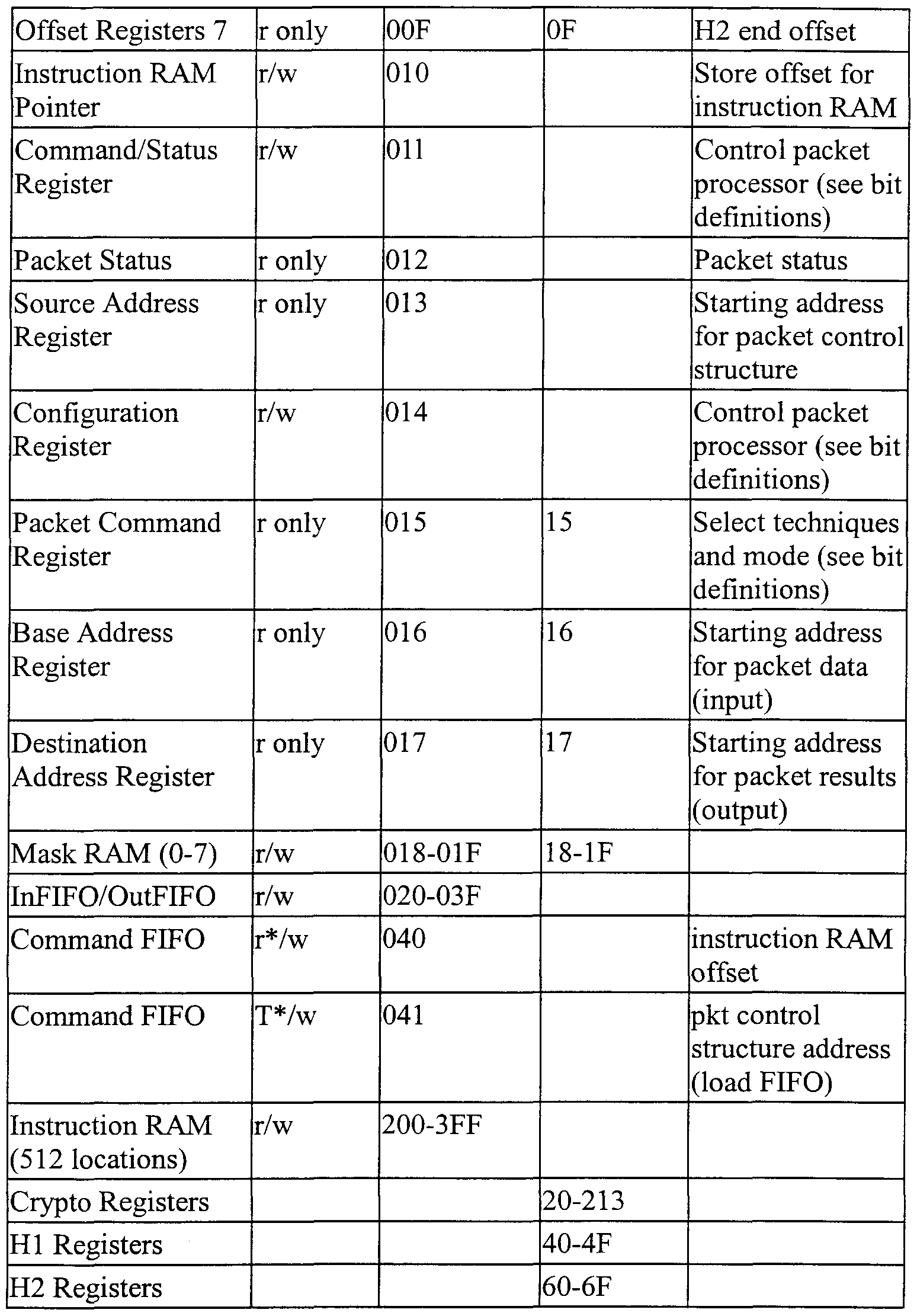
The following Table A indicates a representative example of the packet processor's 404 registers and memories. All offset and size registers are 16-bit wide and indicate the number of bytes. However, the packet processor 404 ignores the two least significant bits since everything has to be on a 32-bit boundary. All offset registers increment while executing the Write data instruction.
Table A
Figure imgf000017_0001
Figure imgf000018_0001
r* = reading command FIFO via PLB bus does not advance FIFO pointer
Packet Processor Instructions The following Table B provides a representative example of packet processor 404 instructions. Table B
Instructions Description
Load [#words] • [#word] - 10 bits wide
• Load the specified number of 32-bit words into the Source Size Register and start transferring data into the CU InFIFO using the PLB Master Read interface until size reaches zero
• The Source Address Register specifies the source address.
• If the InDMA Enable bit of the command register is clear, no data transfer will occur.
• Storex [start • [start address] - 7 bits wide address] [count]
• [count] - 3 bits wide
• Store [count + 1 ] words from the CU InFIFO (unmodified, except as mentioned below) to registers/memory beginning from the specified [start address].
• Destinations supported for this instruction are the following:
• CU: Mask RAM, Base Address Register, Destination Address Register, Status Destination Address Register, Packet Command Register, Offset registers (0-7), and Size Registers (0-3).
• Cores: All registers in the Crypto, HI, and H2 cores. Need to execute the Wait instruction to make sure the cores are ready to accept data.
• Storing size to Size Register I also cause (i) Crypto end offset to be computed and stored in Offset Register 5 and (ii) Crypto destination address to be computed and. stored in Crypto Destination Address Register.
• Storing size to Size Register 2 also cause (i) HI end offset to be computed and stored in Offset Register 6 and (ii) HI destination address to be computed and stored in HI Destination Address Register.
• Storing size to Size Register 3 also cause (i) H2 end offset to be computed and stored in Offset Register 7 and (ii) H2 destination address to be computed and stored in H2 Destination Address Register.
• This instruction can also be used to load commands (based on the information provided in the Configuration Register, Command Register, Packet
Figure imgf000020_0001
Figure imgf000021_0001
Command FIFO Format
The Command FIFO format is 8 bits deep and 41 -bit wide. The following is the format:
Bits [40:32] specify the instruction RAM offset. This field is updated by writing to PLB address 0x040 with the offset on bits [8:0] of the data bus. This field is stored in a 9-bit register and is entered into the Command FIFO when the packet control structure address is updated. Bits [31 :01] specify the packet control structure address. Writing to PLB address 0x041 causes the entire 41 bits to be loaded into the Command FIFO.
Outbound Packet Processing Instructions
The following Table C provides a representative example of instructions used in outbound packet processing:
Table C
Figure imgf000022_0001
Figure imgf000023_0001
Figure imgf000024_0001
* If destination is RAM, remove these instructions to improve performance. Inbound Packet Processing Instructions
The following Table D provides a representative example of instructions used in outbound packet processing:
Table D
Figure imgf000024_0002
Figure imgf000025_0001
Figure imgf000026_0001
• If destination is RAM, remove these instructions to improve performance.
Control Unit Tables
The following Tables E, F, and G provide representative examples of registers in the control unit.
Table E
Figure imgf000026_0002
Figure imgf000027_0001
Table F
Figure imgf000027_0002
Figure imgf000028_0001
Table G
Figure imgf000028_0002
Figure imgf000029_0001
Figure imgf000030_0001
Figure imgf000031_0001
Status Block
The following Table H provides a representative example of the status block command and status register:
Table H
Figure imgf000031_0002
Figure imgf000032_0001
IP Security Encryption Techniques
The goal of the IP security encryption techniques is to do the following transformations:
• DES - ECB and CBC
• 3DES - ECB and outer CBC • RC4
The code performance of the IP security encryption techniques are as follows:
DES: 8 bytes/ 8 clocks
3DES: 8 bytes/ 24 clocks
RC4: I byte / 1 clock (Initialization: 384 clocks) The following Table I provides a representative example of additional information about the IP security encryption techniques:
Table I
Figure imgf000033_0001
In one preferred representative example, the Crypto block 108 performs RC4, DES and 3DES encryption techniques. Input text is either read in by the PLB Master read interface or provided by the packet processor control unit 106. The Crypto block begins execution following the writing to the Command/Status Register. The completion of processing is indicated by the transition of the Busy bit in the Command/Status Register from a one to a zero. As a representative example, the PLB Address for the Crypto Configuration Register is: 0x000200, and this register can be updated at any time. The following Table J provides a representative example of information about the crypto configuration register:
Table J
Figure imgf000034_0001
Further to the above representative example, the PLB Address of the Key Length Register is: 0x000204. This 6-bit register contains the key length in number of bytes. Maximum key length is 32 bytes. READ and WRITE are not allowed while RC4 Init Busy is high. The PLB Addresses of the Key Registers are: 0000208, 0x00020C, 0000210, 0000214, 0000218, 000021C, 0000220, 0x000224. These 8 32-bit registers store the key. The register at PLB address 0x208 holds the most significant word, with the leftmost character of the key in the 31 :24 bit position.
For DES and 3DES, the following are keys and associated registers:
Key 1 [63:0] is stored in registers at PLB address [0000208
000020C].
Key 2 [63:0] is stored in registers at PLB address [0000210 0000214]. Key 3 [63:0] is stored in registers at PLB address (0000218
000021C].
Each 64-bit key is loaded into the DES/3DES engine the same clock cycle when a write to the later address (000020C, 0000214, 0x00021C) is performed. Moreover, READ and WRITE operations are not allowed while RC4 Init Busy is high.
In the above-representative example, the PLB Addresses for the DES TV Registers are: 0000228, 0x0022C. These 2 32-bit registers store the initialization vector for DES/3DES CBC mode. The register at PLB address 0x00228 holds the most significant 32-bit word, with the leftmost character of the vector in the 31:24 bit position. WRITE operations are not allowed while Busy is high.
Further to the above representative example, the PLB Address of the Source Address Register is: 0x000230. This 32-bit source address register points to the location where the input data to the crypto block will be read. The PLB Address of the Destination Address Register is: 0x000234. This 32-bit destination address register points to the location where the output data from the hash block will be written.
Further to the above example, the PLB Address for the Crypto Command Status Register is : 0x000238. Writing to this register starts the Crypto block processing. Writing to this register is inhibited while the busy bit is set. A representative example of this register is defined in Table K, which the "crypto" command/status register information.
Table K
Figure imgf000035_0001
Figure imgf000036_0001
Further to the above example, the PLB Address for the FIFO is: 0x100000 - OxlFFFFF. The InFIFO and OutFIFO may be accessed using an address in the above address range. The Endian bit in the Command/Status register must be written to indicate the byte ordering of the data to be written to and read from the FIFOs.
Data is written into the InFIFO. Data is read from the OutFIFO. The FIFOs are accessible via the PLB bus only when the DMA enable bit is set low.
IP Security HMAC Block The IP security HMAC blocks may use one or a combination of the following authentication techniques:
• HMAC-MD5 (-96)
• HMAC-SHA-I (-96) • MD5
• SHA-1 The HMAC technique is a keyed hashing technique for message authentication. The HMAC technique operates in combination with a hash function and requires a key. The following equation describes the HMAC technique:
Hash ( Key XOR opad, Hash ( Key XOR ipad, text ) );
For higher performance, the technique may generate the inner IV (Hash ( Key XOR ipad)) and outer IV (Hash ( Key XOR opad)) for each key and store them for later use. When keyed hashing is required, the stored inner IV and outer IV stored for that key are provided, and the HMAC update or HMAC update and final command are used to perform the hash. Table L provides a representative example of authentication commands.
Table L
Figure imgf000037_0001
Figure imgf000038_0001
The HMAC block performs Keyed-hashing for message authentication and hash techniques SHA-1 and MD5. Input data is either read in by the PLB Master read interface or provided by the packet processor control unit. The HMAC block begins execution following the writing to the Command/Status Register. Processing is completed when the Busy bit in the Command/Status Register transitions from a one to a zero.
Further to the above example, the PLB Address of the HMAC Configuration Register is [5:2]: 0x0. This register can be updated at any time. The following Table M provides a representative example of HMAC configuration register information.
Table M
Figure imgf000038_0002
The PLB Addresses for the Length Registers are- 0x1, 0x2. The 61 -bit length indicates the number of bytes in the message. Register at PLB address 0x1 contains the lower 32-bit word. Register at PLB address 0x2 contains the upper 29 bits. The PLB Addresses for the Outer IV Register are: 0x3 - 0x7. These registers store the outer initial value for HMAC.
The PLB Addresses for the Hash Register are: 0x8 - OxC. These registers store the hash value. Reading these registers returns the hash value of the last 512 bit block, which has been hashed. Writing to these registers sets the initial hash value for the next block to be hashed (this is also referred to as the inner initial value for HMAC). The register at PLB address 0x8 contains the most significant word. The register at PLB address OxC is not used for MD5. Hash values read from the registers should be written back to the registers the same way. The final result begins with the high-order byte of regAA (PLB address 0x8) and ends with the low- order byte of regDD (PLB address OxB) for MD5 and of regEE (PLB address OxC) for SHA-1, with the following:
MD5=> A3 A2 Al... B3 ... C3 ... D3 D2 DI DO
SHA-1 -> A3 A2 Al . B3 .. C3 .. D3 E3 E2 El E0
(i.e., byte swapping is automatically done for the final MD5 block to achieve the above result).
The PLB Address for the Source Address Register is: OxD. This 32-bit source address register points to the location where the input data to the hash block will be read.
The PLB Address for the Destination Address Register is: OxE. This 32-bit destination address register points to the location where the output data from the hash block will be written. The PLB Address for the HMAC Command/Status Register is: OxF. Writing to this register starts the HMAC block processing. Writing to this register is inhibited while the busy bit is set. The following Table N contains a representative example of HMAC command/status register information. Table N
Figure imgf000040_0001
Figure imgf000041_0001
Conclusion
This concludes the description of the preferred embodiment of the invention. The following describes some alternative embodiments for accomplishing the present invention. For example, any type of computer, such as a mainframe, minicomputer, or personal computer, or computer configuration, such as a timesharing mainframe, local area network, or standalone personal computer, could be used with the present invention.
The foregoing description of the preferred embodiment of the invention has been presented for the purposes of illustration and description. It is not intended to be exhaustive or to limit the invention to the precise form disclosed. Many modifications and variations are possible in light of the above teaching. It is intended that the scope of the invention be limited not by this detailed description, but rather by the claims appended hereto.

Claims

WHAT IS CLAIMED IS:
1. A packet processor comprising: a control unit having a data input path; at least one encryption unit; a first authentication unit; a second authentication unit; a local data path, independent of the data input path to the control unit, coupling the control unit to each of the encryption and authentication units; and a second data path from the encryption unit to each authentication unit, including a data path from the first authentication unit to the second authentication unit.
2. A packet processor as recited in claim 1 , wherein said data input path of the control unit is coupled to a processor bus and each of said encryption and authentication units comprises a data input path coupled to the processor bus.
3. A packet processor as recited in claim 1, wherein said data input path of the control unit is coupled to a processor bus and each of said encryption and authentication units comprises a data input path to the processor bus and means for reading and writing data on the processor bus.
4. A packet processor as recited in claim 1 , wherein said second data path comprises a daisy-chain connection between the encryption and authentication units.
5. A packet processor as recited in claim 1 , wherein said data input path of the control unit is coupled to a processor bus and each of said control, encryption and authentication units comprises a data output path coupled to the processor bus.
6. A method of processing data packets comprising: coupling a control unit to a first data path; receiving first and second data packets in the control unit from the first data path; providing a plurality of processing units in data communication with the control unit over a second data path, independent of the first data path, said processing units including at least one encryption unit and at least one authentication unit; providing data of the first data packet from the control unit to one of the processing units, over the second data path; processing said data from the first data packet with said one of the processing units to provide output data for the first data packet from said one of the processing units; communicating said output data for the first data packet from said one of the processing units to another of the processing units for further processing; and providing data from the second data packet to said one of the processing units, while said other processing unit further processes the output data for the first data packet.
7. A method as recited in claim 6, wherein said one of the processing units comprises an encryption unit and said other of said processing units comprises an authentication unit.
8. A method as recited in claim 6, wherein said at least one authentication unit comprises a first and second authentication units.
9. A method as recited in claim 6, wherein said step of communicating the output data from one of the processing units to another of the processing units comprises communicating said output data over a daisy-chain connection between said processing units.
10. A method of processing data in a computer, the method comprising the steps of: performing encryption on a first data packet; and after completion of the encryption of the first data packet, performing authentication of the first data packet, and performing encryption of a second data packet prior to completion of authentication of the first data packet.
11. The method of claim 10, wherein the authentication is a first authentication, further comprising the step of performing a second authentication on the first data packet of data.
12. The method of claim 11, wherein the first authentication is performed on the encrypted first data packet.
13. The method of claim 11 , wherein the first authentication appends data to the encrypted first data packet.
14. The method of claim 13, wherein the second authentication is performed on the encrypted first data packet and the appended data.
15. The method of claim 11 , further comprising the step of performing the encryption of the second data packet after beginning the second authentication of the first data packet.
16. A method of processing data in a computer, the method comprising the steps of: encrypting a first data packet with an encryption module; authenticating the encrypted first data packet with a first authentication module; encrypting a second data packet with the encryption module while authenticating the first data packet with the first authentication module; and authenticating the second data packet with the first authentication module.
17. An apparatus for processing data, comprising: a computer having a data storage device connected thereto, wherein the data storage device stores a data; one or more computer programs, performed by the computer, for performing encryption on a first data packet, and, after completion of the encryption of the first data packet, performing authentication of the first data packet, and performing encryption of a second data packet prior to completion of authentication of the first data packet.
18. The apparatus of claim 17, wherein the authentication is a first authentication, further comprising means for performing a second authentication on the first data packet of data.
19. The apparatus of claim 18, wherein the first authentication is performed on the encrypted first data packet.
20. The apparatus of claim 18, wherein the first authentication appends data to the encrypted first data packet.
21. The apparatus of claim 20, wherein the second authentication is performed on the encrypted first data packet and the appended data.
22. The apparatus of claim 18, further comprising the means for performing the encryption of the second data packet after beginning the second authentication of the first data packet.
23. An apparatus for processing data, comprising: a computer having a data storage device connected thereto, wherein the data storage device stores a data; one or more computer programs, performed by the computer, for encrypting a first data packet with an encryption module, authenticating the encrypted first data packet with a first authentication module, encrypting a second data packet with the encryption module while authenticating the first data packet with the first authentication module, and authenticating the second data packet with the first authentication module.
24. An article of manufacture comprising a computer program carrier readable by a computer and embodying one or more instructions executable by the computer to perform method steps for processing data, the method comprising the steps of: performing encryption on a first data packet; and after completion of the encryption of the first data packet, performing authentication of the first data packet, and performing encryption of a second data packet prior to completion of authentication of the first data packet.
25. The article of manufacture of claim 24, wherein the authentication is a first authentication, further comprising the step of performing a second authentication on the first data packet of data.
26. The article of manufacture of claim 25, wherein the first authentication is performed on the encrypted first data packet.
27. The article of manufacture of claim 25, wherein the first authentication appends data to the encrypted first data packet.
28. The article of manufacture of claim 27, wherein the second authentication is performed on the encrypted first data packet and the appended data.
29. The article of manufacture of claim 25, further comprising the step of performing the encryption of the second data packet after beginning the second authentication of the first data packet.
30. An article of manufacture comprising a computer program carrier readable by a computer and embodying one or more instructions executable by the computer to perform method steps for processing data, the method comprising the steps of: encrypting a first data packet with an encryption module; authenticating the encrypted first data packet with a first authentication module; encrypting a second data packet with the encryption module while authenticating the first data packet with the first authentication module; and authenticating the second data packet with the first authentication module.
31. A method of processing data packets comprising: coupling a control unit to a first data path; receiving a first data packet in the control unit from the first data path; providing a plurality of processing units in data communication with the control unit over a second data path, independent of the first data path, said processing units including at least one encryption unit and at least one authentication unit; providing data of the first data packet from the control unit to multiple processing units, over the second data path; processing said data from the first data packet with said multiple processing units in parallel.
32. A method as recited in claim 31 , wherein said plurality of processing units comprises at least one encryption unit and a plurality of authentication units.
PCT/US2001/004599 2000-02-14 2001-02-13 Packet processor WO2001061912A1 (en)

Priority Applications (1)

Application Number Priority Date Filing Date Title
AU2001236970A AU2001236970A1 (en) 2000-02-14 2001-02-13 Packet processor

Applications Claiming Priority (2)

Application Number Priority Date Filing Date Title
US09/503,282 US6983366B1 (en) 2000-02-14 2000-02-14 Packet Processor
US09/503,282 2000-02-14

Publications (1)

Publication Number Publication Date
WO2001061912A1 true WO2001061912A1 (en) 2001-08-23

Family

ID=24001441

Family Applications (1)

Application Number Title Priority Date Filing Date
PCT/US2001/004599 WO2001061912A1 (en) 2000-02-14 2001-02-13 Packet processor

Country Status (3)

Country Link
US (1) US6983366B1 (en)
AU (1) AU2001236970A1 (en)
WO (1) WO2001061912A1 (en)

Cited By (5)

* Cited by examiner, † Cited by third party
Publication number Priority date Publication date Assignee Title
WO2002101978A2 (en) * 2001-06-13 2002-12-19 Corrent Corporation Apparatus and method for a hash processing system using multiple hash storage areas
EP1351432A1 (en) * 2002-03-28 2003-10-08 Broadcom Corporation Methods and apparatus for performing hash operations in a cryptography accelerator
US7213148B2 (en) 2001-06-13 2007-05-01 Corrent Corporation Apparatus and method for a hash processing system using integrated message digest and secure hash architectures
US7266703B2 (en) 2001-06-13 2007-09-04 Itt Manufacturing Enterprises, Inc. Single-pass cryptographic processor and method
EP1324175B1 (en) * 2001-12-28 2018-06-20 Bull SAS Module for securing data by encryption/decryption and/or signature/verification of signature

Families Citing this family (47)

* Cited by examiner, † Cited by third party
Publication number Priority date Publication date Assignee Title
US6694433B1 (en) * 1997-05-08 2004-02-17 Tecsec, Inc. XML encryption scheme
US7600131B1 (en) 1999-07-08 2009-10-06 Broadcom Corporation Distributed processing in a cryptography acceleration chip
ATE249664T1 (en) * 2000-01-18 2003-09-15 Infineon Technologies Ag MICROPROCESSOR ARRANGEMENT WITH ENCRYPTION
US20020061107A1 (en) * 2000-09-25 2002-05-23 Tham Terry K. Methods and apparatus for implementing a cryptography engine
US20020078342A1 (en) * 2000-09-25 2002-06-20 Broadcom Corporation E-commerce security processor alignment logic
US7765580B2 (en) * 2000-12-22 2010-07-27 Entrust, Inc. Method and apparatus for providing user authentication using a back channel
EP2273342A1 (en) 2001-05-24 2011-01-12 Sony Corporation Service providing method and integrated circuit
US7283526B2 (en) * 2001-07-19 2007-10-16 International Business Machines Corporation Method and system for providing a symmetric key for more efficient session identification
US7200227B2 (en) * 2001-07-30 2007-04-03 Phillip Rogaway Method and apparatus for facilitating efficient authenticated encryption
AU2002331784A1 (en) * 2001-08-31 2003-03-18 John W. Hamilton A non-algebraic cryptographic architecture
US7305567B1 (en) * 2002-03-01 2007-12-04 Cavium Networks, In. Decoupled architecture for data ciphering operations
US20030182559A1 (en) * 2002-03-22 2003-09-25 Ian Curry Secure communication apparatus and method for facilitating recipient and sender activity delegation
US7376826B2 (en) * 2002-05-31 2008-05-20 Broadcom Corporation Methods and apparatus for performing encryption and authentication
US7773754B2 (en) * 2002-07-08 2010-08-10 Broadcom Corporation Key management system and method
US20040103086A1 (en) * 2002-11-26 2004-05-27 Bapiraju Vinnakota Data structure traversal instructions for packet processing
US20040123120A1 (en) * 2002-12-18 2004-06-24 Broadcom Corporation Cryptography accelerator input interface data handling
US20040123123A1 (en) * 2002-12-18 2004-06-24 Buer Mark L. Methods and apparatus for accessing security association information in a cryptography accelerator
US7568110B2 (en) 2002-12-18 2009-07-28 Broadcom Corporation Cryptography accelerator interface decoupling from cryptography processing cores
US7434043B2 (en) 2002-12-18 2008-10-07 Broadcom Corporation Cryptography accelerator data routing unit
US20040193763A1 (en) * 2003-03-28 2004-09-30 Fujitsu Limited Inter-bus communication interface device and data security device
US20040230813A1 (en) * 2003-05-12 2004-11-18 International Business Machines Corporation Cryptographic coprocessor on a general purpose microprocessor
US8949548B2 (en) * 2003-09-12 2015-02-03 Broadcom Corporation System and method of sharing memory by arbitrating through an internal data bus
JP4263976B2 (en) * 2003-09-24 2009-05-13 株式会社東芝 On-chip multi-core tamper resistant processor
US7685436B2 (en) * 2003-10-02 2010-03-23 Itt Manufacturing Enterprises, Inc. System and method for a secure I/O interface
FR2862397A1 (en) * 2003-11-13 2005-05-20 St Microelectronics Sa Electronic apparatus booting method, involves extending secure domain to application processor, when application and boot-strap processors are authenticated, and booting operating system of processors to store data in protected part of RAM
US7512787B1 (en) * 2004-02-03 2009-03-31 Advanced Micro Devices, Inc. Receive IPSEC in-line processing of mutable fields for AH algorithm
US20050249228A1 (en) * 2004-05-05 2005-11-10 Linden Cornett Techniques for providing scalable receive queues
US7895431B2 (en) * 2004-09-10 2011-02-22 Cavium Networks, Inc. Packet queuing, scheduling and ordering
US20060136717A1 (en) 2004-12-20 2006-06-22 Mark Buer System and method for authentication via a proximate device
US8295484B2 (en) * 2004-12-21 2012-10-23 Broadcom Corporation System and method for securing data from a remote input device
EP1869886B1 (en) * 2005-04-06 2020-09-02 Avago Technologies International Sales Pte. Limited Secure conditional access and digital rights management in multimedia processor
US7535907B2 (en) 2005-04-08 2009-05-19 Oavium Networks, Inc. TCP engine
US8051299B2 (en) * 2006-03-20 2011-11-01 Hewlett-Packard Development Company, L.P. Computer security method and computer system
US8467527B2 (en) 2008-12-03 2013-06-18 Intel Corporation Efficient key derivation for end-to-end network security with traffic visibility
US20090119510A1 (en) * 2007-11-06 2009-05-07 Men Long End-to-end network security with traffic visibility
JP5294761B2 (en) * 2008-08-29 2013-09-18 パナソニック株式会社 Secure communication device, secure communication method, and program
US10133883B2 (en) * 2009-02-09 2018-11-20 International Business Machines Corporation Rapid safeguarding of NVS data during power loss event
WO2010098778A1 (en) * 2009-02-26 2010-09-02 Lsi Corporation Cipher independent interface for cryptographic hardware service
US9191211B2 (en) * 2009-02-27 2015-11-17 Atmel Corporation Data security system
US20110213711A1 (en) * 2010-03-01 2011-09-01 Entrust, Inc. Method, system and apparatus for providing transaction verification
US8200864B1 (en) * 2010-03-02 2012-06-12 Amazon Technologies, Inc. Pre-defined multiblock transfers
US9176838B2 (en) 2012-10-19 2015-11-03 Intel Corporation Encrypted data inspection in a network environment
EP2741462A1 (en) * 2012-12-06 2014-06-11 ST-Ericsson SA Methods for opportunistic sensing
US9524399B1 (en) * 2013-04-01 2016-12-20 Secturion Systems, Inc. Multi-level independent security architecture
US9680653B1 (en) * 2016-10-13 2017-06-13 International Business Machines Corporation Cipher message with authentication instruction
US11070523B2 (en) * 2017-04-26 2021-07-20 National University Of Kaohsiung Digital data transmission system, device and method with an identity-masking mechanism
CN112003689A (en) * 2020-08-31 2020-11-27 北京三未信安科技发展有限公司 SSL data packet rapid processing method, system and electronic equipment

Citations (4)

* Cited by examiner, † Cited by third party
Publication number Priority date Publication date Assignee Title
US5774551A (en) * 1995-08-07 1998-06-30 Sun Microsystems, Inc. Pluggable account management interface with unified login and logout and multiple user authentication services
US5778071A (en) * 1994-07-12 1998-07-07 Information Resource Engineering, Inc. Pocket encrypting and authenticating communications device
US5923756A (en) * 1997-02-12 1999-07-13 Gte Laboratories Incorporated Method for providing secure remote command execution over an insecure computer network
US5995626A (en) * 1995-08-04 1999-11-30 Hitachi, Ltd. Electronic shopping method, electronic shopping system and document authenticating method relating thereto

Family Cites Families (7)

* Cited by examiner, † Cited by third party
Publication number Priority date Publication date Assignee Title
US5631960A (en) * 1995-08-31 1997-05-20 National Semiconductor Corporation Autotest of encryption algorithms in embedded secure encryption devices
US5911077A (en) * 1996-05-31 1999-06-08 Micron Electronics, Inc. System for multithreaded disk drive operation in a computer system
EP0860823A4 (en) * 1996-07-15 2001-05-02 Toshiba Kk Apparatus having digital interface, network system employing the apparatus and copy protection method
US6061449A (en) * 1997-10-10 2000-05-09 General Instrument Corporation Secure processor with external memory using block chaining and block re-ordering
ATE429748T1 (en) * 1998-01-02 2009-05-15 Cryptography Res Inc LEAK RESISTANT CRYPTOGRAPHIC METHOD AND APPARATUS
US6243774B1 (en) * 1998-06-30 2001-06-05 International Business Machines Corporation Apparatus program product and method of managing computer resources supporting concurrent maintenance operations
US6201871B1 (en) * 1998-08-19 2001-03-13 Qualcomm Incorporated Secure processing for authentication of a wireless communications device

Patent Citations (4)

* Cited by examiner, † Cited by third party
Publication number Priority date Publication date Assignee Title
US5778071A (en) * 1994-07-12 1998-07-07 Information Resource Engineering, Inc. Pocket encrypting and authenticating communications device
US5995626A (en) * 1995-08-04 1999-11-30 Hitachi, Ltd. Electronic shopping method, electronic shopping system and document authenticating method relating thereto
US5774551A (en) * 1995-08-07 1998-06-30 Sun Microsystems, Inc. Pluggable account management interface with unified login and logout and multiple user authentication services
US5923756A (en) * 1997-02-12 1999-07-13 Gte Laboratories Incorporated Method for providing secure remote command execution over an insecure computer network

Cited By (9)

* Cited by examiner, † Cited by third party
Publication number Priority date Publication date Assignee Title
WO2002101978A2 (en) * 2001-06-13 2002-12-19 Corrent Corporation Apparatus and method for a hash processing system using multiple hash storage areas
WO2002101978A3 (en) * 2001-06-13 2003-04-03 Corrent Corp Apparatus and method for a hash processing system using multiple hash storage areas
US7213148B2 (en) 2001-06-13 2007-05-01 Corrent Corporation Apparatus and method for a hash processing system using integrated message digest and secure hash architectures
US7249255B2 (en) 2001-06-13 2007-07-24 Corrent Corporation Apparatus and method for a hash processing system using multiple hash storage areas
US7266703B2 (en) 2001-06-13 2007-09-04 Itt Manufacturing Enterprises, Inc. Single-pass cryptographic processor and method
EP1324175B1 (en) * 2001-12-28 2018-06-20 Bull SAS Module for securing data by encryption/decryption and/or signature/verification of signature
EP1351432A1 (en) * 2002-03-28 2003-10-08 Broadcom Corporation Methods and apparatus for performing hash operations in a cryptography accelerator
US7400722B2 (en) 2002-03-28 2008-07-15 Broadcom Corporation Methods and apparatus for performing hash operations in a cryptography accelerator
US8315381B2 (en) 2002-03-28 2012-11-20 Broadcom Corporation Methods and apparatus performing hash operations in a cryptography accelerator

Also Published As

Publication number Publication date
AU2001236970A1 (en) 2001-08-27
US6983366B1 (en) 2006-01-03

Similar Documents

Publication Publication Date Title
WO2001061912A1 (en) Packet processor
US6021201A (en) Method and apparatus for integrated ciphering and hashing
US7941662B2 (en) Data transfer efficiency in a cryptography accelerator system
US9954826B2 (en) Scalable and secure key management for cryptographic data processing
EP1423963B1 (en) Techniques for offloading cryptographic processing for multiple network traffic streams
US8374343B2 (en) DES hardware throughput for short operations
US4881263A (en) Apparatus and method for secure transmission of data over an unsecure transmission channel
US7336783B2 (en) Cryptographic systems and methods supporting multiple modes
US5818939A (en) Optimized security functionality in an electronic system
US7961882B2 (en) Methods and apparatus for initialization vector pressing
US8351445B1 (en) Network interface systems and methods for offloading segmentation and/or checksumming with security processing
US6725371B1 (en) Secure packet processor
US20040225885A1 (en) Methods and systems for efficiently integrating a cryptographic co-processor
US7657757B2 (en) Semiconductor device and method utilizing variable mode control with block ciphers
EP3803672B1 (en) Memory-efficient hardware cryptographic engine
KR20090085685A (en) Data-mover controller with plural registers for supporting ciphering operations
US6549622B1 (en) System and method for a fast hardware implementation of RC4
JP2004070499A (en) Memory device, and enciphering/decoding method
US20050278548A1 (en) System and method for performing secure communications in a wireless local area network
CN111832051B (en) Symmetric encryption and decryption method and system based on FPGA
JP5149863B2 (en) Communication device and communication processing method
Data 2.5 IETF References

Legal Events

Date Code Title Description
AK Designated states

Kind code of ref document: A1

Designated state(s): AE AG AL AM AT AU AZ BA BB BG BR BY BZ CA CH CN CR CU CZ DE DK DM DZ EE ES FI GB GD GE GH GM HR HU ID IL IN IS JP KE KG KP KR KZ LC LK LR LS LT LU LV MA MD MG MK MN MW MX MZ NO NZ PL PT RO RU SD SE SG SI SK SL TJ TM TR TT TZ UA UG UZ VN YU ZA ZW

AL Designated countries for regional patents

Kind code of ref document: A1

Designated state(s): GH GM KE LS MW MZ SD SL SZ TZ UG ZW AM AZ BY KG KZ MD RU TJ TM AT BE CH CY DE DK ES FI FR GB GR IE IT LU MC NL PT SE TR BF BJ CF CG CI CM GA GN GW ML MR NE SN TD TG

121 Ep: the epo has been informed by wipo that ep was designated in this application
DFPE Request for preliminary examination filed prior to expiration of 19th month from priority date (pct application filed before 20040101)
REG Reference to national code

Ref country code: DE

Ref legal event code: 8642

Ref country code: DE

Ref legal event code: 8642

122 Ep: pct application non-entry in european phase
NENP Non-entry into the national phase

Ref country code: JP