DOWNCONVERTING DECODER FOR INTERLACED PICTURES
Technical Field of the Invention
The present invention relates to a
downconverting decoder for downconverting and decoding
high resolution encoded video for display by a lower
resolution receiver.
Background of the Invention
The international standard ISO/IEC 13818-2
(Generic Coding of Motion Pictures and Associated Audio
Information: Video) and the "Guide to the use of the
ATSC Digital Television Standard" describe a system,
known as MPEG-2, for encoding and decoding digital video
data. According to this system, digital video data is
encoded as a series of code words in a complicated manner
that causes the average length of the code words to be
much smaller than would be the case if, for example, each
pixel in every frame was coded as an eight bit value.
This type of encoding is also known as data compression.
The standard allows for encoding of video over
a wide range of resolutions, including higher resolutions
commonly known as HDTV. In MPEG-2, encoded pictures are
made up of pixels. Each 8x8 array of pixels is known as
a block, and a 2x2 array of blocks is known as a macroblock. Compression is achieved by using well known
techniques including (i) prediction (motion estimation in the encoder and motion compensation in the decoder) , (ii)
two dimensional discrete cosine transform (DCT) which is
performed on 8x8 blocks of pixels, (iii) quantization of the resulting DCT coefficients, and (iv) Huffman and run/level coding. In MPEG-2 encoding, pictures which are
encoded without prediction are referred to as I pictures,
pictures which are encoded with prediction from previous
pictures are referred to as P pictures, and pictures which are encoded with prediction from both previous and
subsequent pictures are referred to as B pictures.
An MPEG-2 encoder 10 is shown in simplified
form in Figure 1. Data representing macroblocks of pixel
values are fed to both a subtractor 12 and a motion
estimator 14. In the case of P pictures and B pictures,
the motion estimator 14 compares each new macroblock
(i.e., a macroblock to be encoded) with the macroblocks
in a reference picture previously stored in a reference
picture memory 16. The motion estimator 14 finds the
macroblock in the stored reference picture that most
closely matches the new macroblock.
The motion estimator 14 reads this matching
macroblock (known as a predicted macroblock) out of the
reference picture memory 16 and sends it to the
subtractor 12 which subtracts it, on a pixel by pixel
basis, from the new macroblock entering the MPEG-2
encoder 10. The output of the subtractor 12 is an error,
or residual, that represents the difference between the
predicted macroblock and the new macroblock being
encoded. This residual is often very small. The
residual is transformed from the spatial domain by a two
dimensional DCT 18. The DCT residual coefficients
resulting from the two dimensional DCT 18 are then
quantized by a quantization block 20 in a process that
reduces the number of bits needed to represent each
coefficient. Usually, many coefficients are effectively
quantized to zero. The quantized DCT coefficients are
Huffman and run/level coded by a coder 22 which further
reduces the average number of bits per coefficient.
The motion estimator 14 also calculates a
motion vector (mv) which represents the horizontal and
vertical displacement of the predicted macroblock in the
reference picture from the position of the new macroblock
in the current picture being encoded. It should be noted
that motion vectors may have pixel resolution which
achieved by linear interpolation between adjacent pixels.
The data encoded by the coder 22 are combined with the
motion vector data from the motion estimator 14 and with
other information (such as an indication of whether the
picture is an I, P or B picture) , and the combined data
are transmitted to a receiver that includes an MPEG-2
decoder 30.
For the case of P pictures, the quantized DCT
coefficients from the quantization block 20 are also
supplied to an internal loop that represents the
operation of the MPEG-2 decoder 30. Within this internal
loop, the residual from the quantization block 20 is
inverse quantized by an inverse quantization block 24 and is inverse DCT transformed by an inverse discrete cosine
transform (IDCT) block 26. The predicted macroblock,
that is read out of the reference picture memory 16 and
that is supplied to the subtractor 12, is also added back to the output of the IDCT block 26 on a pixel by pixel
basis by an adder 28, and the result is stored back into the reference picture memory 16 in order to serve as a
macroblock of a reference picture for predicting
subsequent pictures. The object of this internal loop is to have the data in the reference picture memory 16 of the MPEG-2 encoder 10 match the data in the reference
picture memory of the MPEG-2 decoder 30. B pictures are
not stored as reference pictures. In the case of I pictures, no motion estimation
occurs and the negative input to the subtractor 12 is
forced to zero. In this case, the quantized DCT
coefficients provided by the two dimensional DCT 18
represent transformed pixel values rather than residual
values, as is the case with P and B pictures. As in the
case of P pictures, decoded I pictures are stored as
reference pictures.
The MPEG-2 decoder 30 illustrated in Figure 2
is a simplified showing of an MPEG-2 decoder. The
decoding process implemented by the MPEG-2 decoder 30 can be thought of as the reverse of the encoding process
implemented by the MPEG-2 encoder 10. The received
encoded data is Huffman and run/level decoded by a Huffman and run/level decoder 32. Motion vectors and
other information are parsed from the data stream flowing through the Huffman and run/level decoder 32. The motion vectors are fed to a motion compensator 34. Quantized
DCT coefficients at the output of the Huffman and
run/level decoder 32 are fed to an inverse quantization
block 36 and then to an IDCT block 38 which transforms
the inverse quantized DCT coefficients back into the
spatial domain.
For P and B pictures, each motion vector is
translated by the motion compensator 34 to a memory
address in order to read a particular macroblock
(predicted macroblock) out of a reference picture memory
42 which contains previously stored reference pictures.
An adder 44 adds this predicted macroblock to the
residual provided by the IDCT block 38 in order to form
reconstructed pixel data. For I pictures, there is no
reference picture so that the prediction provided to the
adder 44 is forced to zero. For I and P pictures, the
output of the adder 42 is fed back to the reference
picture memory 42 to be stored as a reference picture for
future predictions.
The MPEG encoder 10 can encode sequences of
progressive or interlaced pictures. For sequences of
interlaced pictures, pictures may be encoded as field
pictures or as frame pictures. For field pictures, one
picture contains the odd lines of the raster, and the
next picture contains the even lines of the raster. All
encoder and decoder processing is done on fields. Thus,
the DCT transform is performed on 8x8 blocks that contain
all odd or all even numbered lines. These blocks are
referred to as field DCT coded blocks.
On the other hand, for frame pictures, each
picture contains both odd and even numbered lines of the
raster. Macroblocks of frame pictures are encoded as
frames in the sense that an encoded macroblock contains
both odd and even lines. However, the DCT performed on
the four blocks within each macroblock of a frame picture
may be done in two different ways. Each of the four DCT
transform blocks in a macroblock may contain both odd and
even lines (frame DCT coded blocks) , or alternatively two
of the four DCT blocks in a macroblock may contain only
the odd lines of the macroblock and the other two blocks
may contain only the even lines of the macroblock (field
DCT coded blocks) . The coding decision as to which way
to encode a picture may be made adaptively by the MPEG-2
encoder 10 based upon which method results in better data
compression.
Residual macroblocks in field pictures are
field DCT coded and are predicted from a reference field.
Residual macroblocks in frame pictures that are frame DCT
coded are predicted from a reference frame. Residual
macroblocks in frame pictures that are field DCT coded
have two blocks predicted from one reference field and
two blocks predicted from either the same or other
reference field.
For sequences of progressive pictures, all
pictures are frame pictures with frame DCT coding and
frame prediction.
MPEG-2, as described above, includes the
encoding and decoding of video at high resolution (HDTV)
In order to permit people to use their existing NTSC
televisions in order to view HDTV transmitted programs, it is desirable to provide a decoder that decodes high resolution MPEG-2 encoded data as reduced resolution
video data for display on existing NTSC televisions.
(Reducing the resolution of television signals is often
called down conversion decoding.) Accordingly, such a
downconverting decoder would allow the viewing of HDTV
signals without requiring viewers to buy expensive HDTV
displays.
There are known techniques for making such a
downconverting decoder such that it requires less
circuitry and is, therefore, cheaper than a decoder that
outputs full HDTV resolution. One of these methods is
disclosed in U.S. Patent 5,262,854. The down conversion
technique disclosed there is explained herein in
connection with a down convertor 50 shown in Figure 3.
The down convertor 50 includes a Huffman and run/level
decoder 52 and an inverse quantization block 54 which
operate as previously described in connection with the
Huffman and run/level decoder 32 and the inverse
quantization block 36 of Figure 2. However, instead of
utilizing the 8x8 IDCT block 38 as shown in Figure 2, the
down convertor 50 employs a downsampler 56 which discards
the forty-eight high order DCT coefficients of an 8x8
block and performs a 4x4 IDCT on the remaining 4x4 array
of DCT coefficients. This process is usually referred to
as DCT domain downsampling. The result of this
downsampling is effectively a filtered and downsampled
4x4 block of residual samples (for P or B pictures) or
pixels for I pictures.
For residual samples, a prediction is added by
an adder 58 to the residual samples from the downsampler
56 in order to produce a decoded reduced resolution 4x4
block of pixels. This block is saved in a reference
picture memory 60 for subsequent predictions.
Accordingly, predictions will be made from a reduced
resolution reference, while predictions made in the
decoder loop within the encoder are made from full
resolution reference pictures. This difference means
that the prediction derived from the reduced resolution
reference will differ by some amount from the
corresponding prediction made by the encoder, resulting
in error in the residual plus prediction sum provided by
the adder 58 (this error is referred to herein as
prediction error) . This error may increase as
predictions are made upon predictions until the reference
is refreshed by the next I picture.
A motion compensator 62 attempts to reduce this
prediction error by using the full resolution motion
vectors, even though the reference picture is at lower
resolution. First, a portion of the reference picture
that includes the predicted macroblock is read from a
reference picture memory 60. This portion is selected
based on all bits of the motion vector except the least
significant bit. This predicted macroblock is
interpolated back to full resolution by a 2x2 prediction
upsample filter 64. Using the full resolution motion
vector (which may include pixel resolution) , a
predicted full resolution macroblock is extracted from
the upsampled portion based upon all of the bits of the
motion vector. Then, a downsampler 66 performs a 2x2
downsampling on the extracted full resolution macroblock
in order to match the resolution of the 4x4 IDCT output
of the downsampler 56. In this way, the prediction from
the reference picture memory 60 is upsampled to match the
full resolution residual pixel structure allowing the use
of full resolution motion vectors. Then, the full
resolution reference picture is downsampled prior to
addition by the adder 58 in order to match the resolution
of the downsampled residual from the downsampler 56.
There are several known good prediction upsam-
pling/downsampling methods that tend to minimize the
prediction error caused by upsampling reference pictures
that have been downsampled with a 4x4 IDCT. These
methods typically involve use of a two dimensional filter
having five to eight taps and tap values that vary both
with the motion vector value for the predicted macroblock
and the position of the current pixel being interpolated
within the predicted macroblock. Such a filter not only
upsamples the reduced resolution reference to full
resolution and subsequently downsamples in a single
operation, but it can also include additional % pixel
interpolation (when required due to a fractional motion
vector) . (See, for example, Minimal Error Drift in
Frequency Scalability for Motion Compensated DCT Coding,
Mokry and Anastassiou, IEEE Transactions on Circui ts and
Systems for Video Technology, August 1994, and Drift
Minimization in Frequency Scaleable Coders Using Block
Based Filtering, Johnson and Princen, IEEE Workshop on
Visual Signal Processing and Communication, Melbourne,
Australia, September 1993.) The objective of such
upsampling and downsampling is for the prediction upsam-
pling filter to be a close spatial domain approximation
to the effective filtering operation done by a 4x4 IDCT.
The following example is representative of the
prediction upsampling/downsampling filter described in
the Mokry and Johnson papers. This example is a one
dimensional example but is easily extended to two
dimensions. Let it be assumed that pixels yl and pixels
y2 as shown in Figure 4 represent two adjacent blocks in
a downsampled reference picture, and that the desired
predicted block stradles the boundary between the two
blocks. The pixels yl are upsampled to the pixels pi by
using a four tap filter with a different set of tap
values for each of the eight calculated pixels pi. The
pixels y2 are likewise upsampled to the pixels p2 by
using the same four tap filter arrangement. (If the
motion vector requires 34 pixel interpolation, this
interpolation is done using linear interpolation to
calculate in between pixel values based on the pixels pi
and p2. ) From these sixteen pixels pi and pixels p2 , an
upsampled prediction consisting of eight pixels q can be
read using the full resolution motion vector. The pixels
q are then filtered and downsampled to pixels q' by an
eight tap filter with a different set of tap values for
each of the four pixels q' . The Johnson paper teaches
how to determine the optimum tap values for these filters
given that the reference picture was downsampled by a
four point IDCT. The tap points are optimum in the sense
that the prediction error is minimized. The Johnson and
Mokry papers also show that the upsampling, linear
interpolation, and downsampling filters can be combined
into a single eight tap filter with tap values that
depend on the motion vector value and the particular
pixels q1 being calculated. Accordingly, this single
eight tap filter allows four pixels q' to be calculated
directly from the eight pixels yl and y2.
The down convertor 50, while generally adequate
for progressive pictures with frame DCT coded blocks,
does not address problems that arise when attempting to
down convert sequences of interlaced pictures with mixed
frame and field DCT coded blocks. These problems arise,
for the most part, with respect to vertical prediction
upsampling, and are described below in a one dimensional
vertical context. Thus, for the purpose of this
description, a full resolution block refers to an eight
pixel vertical column with a downsampled block having a
corresponding vertical column of four pixels.
Let it be assumed that an eight point vertical
column of pixels as shown in column 70 of Figure 5 is
transformed into DCT coefficients by an encoder utilizing
an eight point DCT transform operation. A downconverting
decoder discards the four high order coefficients for
each block and performs a four point IDCT on the
remaining coefficients (DCT domain downsampling) . The
spatial relationship between the original pixels x and
the decoded pixels y is shown by columns 70 and 72. The
pixels y represent the stored reference picture.
Prediction upsampling/downsampling methods,
such as those previously referenced (Mokry, Johnson) ,
which operate on DCT domain downsampled reference
pictures, result in the spatial relationships shown in
Figure 6, where the reference pixels y are first
upsampled to produce upsampled reference pixels p (these
approximate the original pixels x) and the upsampled
reference pixels p are then downsampled to produce down-
sampled reference pixels q. These methods attempt to
effectively reverse the DCT domain downsampling with a
minimal or small error due to the discarding of the high
order DCT coefficients when the 4x4 IDCT is performed.
The objective is for the prediction upsampling filter to
be a close spatial domain approximation to the effective
filtering operation done by a 4x4 IDCT.
The typical operation of such a filter
operating vertically is explained as follows. A portion
of the lower resolution reference picture consisting of
two pixel blocks (e.g., the y1 and y2 pixel blocks of
column 80) overlapped by the desired predicted block is
accessed. As shown in column 82, these two pixel blocks
are upsampled and filtered to approximate the full
resolution reference so that the pixels p1 and p2
approximate full resolution pixels x. Then, the pixels px
and p2 are filtered and downsampled to produce pixels q as
shown in column 84. The pixels q form the predicted
block that is supplied to the adder 58.
This upsampling/downsampling process can either
be a two step filtering process, or the pixels q can be
directly calculated from the pixels y using, for example,
an eight tap filter whose filter coefficients vary with
the motion vector value and the particular pixels q being
calculated, as described in the Johnson and Mokry papers.
As shown in Figure 7, prediction upsampling/downsampling
filters can also include additional pixel interpolation
(approximation of pixel values between original pixels x)
when the motion vector is fractional.
It is noted that the pixels y due to DCT domain
downsampling are effectively spatially located half way
between the original pixels x. This spatial relationship
has important implications because, as previously
explained, the DCT blocks may be frame or field encoded.
For example, if it is assumed that a full resolution
frame consisting of fields A and B is encoded by the
encoder, and if these fields are field DCT encoded, the
DCT domain downsampling must be performed by a down
conversion decoder separately on each field block. The
resulting vertical spatial relationship of pixels in the
downsampled fields a and b with respect to pixels in the
original fields A and B is shown in Figure 8, where the
original encoded fields A and B are shown in column 90
and the downsampled fields a and b are shown in column
92. It should be noted that the pixels b are not evenly
spaced between the pixels a.
On the other hand, with frame DCT encoding,
pixels from fields A and B are combined together into DCT
blocks by the encoder. DCT domain downsampling on these
frame DCT coded blocks results in the pixel spatial
relationship shown in Figure 9, where the original frame
DCT encoded fields A and B are shown in column 94 and the
downsampled frame c is shown in column 96. It should be
noted that the pixels c are evenly spaced.
According to the MPEG-2 standard, a picture may
be encoded with all macroblocks containing frame DCT
coded blocks, with all macroblocks containing field DCT
coded blocks, or with a mix of field and frame coded
macroblocks. Therefore, performing DCT domain
downsampling as shown by the prior art results in
reference pictures that have a varying pixel structure.
An entire reference picture may have the a/b structure
shown in column 92 or the c structure shown in column 96.
On the other hand, a reference picture may be composed of
macroblocks, some having the a/b structure of column 92
and others having the c structure of column 96.
When forming a predicted macroblock, as
previously explained, the reference picture must be
upsampled so that it matches its original full resolution
structure. The prediction upsampling operation is made
more complicated because the two different reference
picture pixel structures shown in columns 92 and 96
require different upsampling processes. Because the
pixels in the c structured reference picture shown in
column 96 have resulted from DCT domain downsampling of a
frame, prediction upsample filtering must be performed on
the reference macroblock as a frame to derive the A and B
fields together. However, because the pixels in the a/b
structured reference pictures shown in column 92 have
resulted from DCT domain downsampling of separate fields,
prediction upsample filtering must be performed
separately on each field (a and b) of the reference
macroblock in order to derive the A and then B fields
shown in column 90.
A further complication is introduced when
reference blocks have a mixed macroblock pixel structure
because predicted macroblocks from the reference picture
may straddle stored reference macroblocks, some having
the c structure and some having the a/b structure . In
this case, two different prediction upsample processes
would have to be executed for different parts of the same
predicted macroblock.
Moreover, a particular disadvantage of using
the c structure shown in column 96 for reference pictures
becomes apparent when it is necessary to do field
prediction from a c structured reference, where the A/B
structured full resolution reference contains high
vertical frequencies. For example, if it is assumed that
at full resolution the A/B reference is entirely composed
of alternating black (A field) and white (B field) lines,
a c structured downsampled reference would be composed of
pixels that are approximately gray due to the mixing of
the A and B pixels that occurs during filtering and
downsampling. However, an a/b structured reference would
have all black pixels for the a field and all white
pixels for the b field because each field is filtered and
downsampled separately. If the encoder decides to do a
field prediction from the A field, a decoder with a c
structured reference would read a prediction consisting
of gray pixels. However, a decoder with an a/b
structured reference would read a much more accurate
prediction from the a field consisting of black pixels.
Thus, the a/b structure avoids the field "mixing" in the
decoder that occurs in the c structure.
The downconverting decoder of the present
invention overcomes one or more of the problems inherent
in the prior art .
Summary of the Invention
In accordance with the present invention, a
method of downconverting received frame and field coded
DCT coefficient blocks to reconstructed pixel field
blocks, wherein the frame and field coded DCT coefficient
blocks have motion vectors associated therewith,
comprises the following steps: a) converting the
received frame coded DCT coefficient blocks to converted
field coded DCT coefficient blocks and performing an IDCT
on the converted field coded DCT coefficient blocks to
produce residual or pixel field blocks; b) directly
performing an IDCT on the received field coded DCT
coefficient blocks to produce residual or pixel field
blocks; c) selecting reference pixel blocks based upon
the motion vectors, upsampling the reference pixel
blocks, and downsampling at least a portion of the
upsampled reference blocks to form a prediction; and,
d) adding the prediction to the residual field blocks to
form reconstructed field blocks.
In a more detailed aspect of the present
invention, an apparatus for downconverting received frame
and field coded DCT coefficient blocks to reconstructed
pixel field blocks comprises an IDCT and a motion
compensator. The IDCT is arranged to convert the
received frame coded DCT coefficient blocks to converted
field coded DCT coefficient blocks and to perform an IDCT
on the converted field coded DCT coefficient blocks and
on the received field coded DCT coefficient blocks in
order to produce downconverted pixel related field
blocks. The motion compensator is arranged to apply
motion compensation, as appropriate, to the downconverted
pixel related field blocks in order to produce the
reconstructed pixel field blocks.
In a further more detailed aspect of the
present invention, an apparatus for downconverting
received frame and field coded DCT coefficient blocks to
downconverted pixel related field blocks comprises first
and second IDCT's. The first IDCT is arranged to convert
the received frame coded DCT coefficient blocks to
converted field coded DCT coefficient blocks and to
perform a downconverting IDCT on the converted field
coded DCT coefficient blocks in order to produce first
downconverted pixel related field blocks. The second
IDCT is arranged to directly perform a downconverting
IDCT on the received field coded DCT coefficient blocks
in order to produce second downconverted pixel related
field blocks.
Brief Description of the Drawings
These and other features and advantages of the
present invention will become more apparent from a
detailed consideration of the invention when taken in
conjunction with the drawings in which:
Figure 1 is a simplified block diagram of a
known MPEG-2 encoder;
Figure 2 is a simplified block diagram of a
known MPEG-2 decoder;
Figure 3 is a block diagram of a known down
conversion decoder for an HDTV application;
Figure 4 - 9 show exemplary sets of pixel data
useful in describing the background of the present
invention;
Figure 10 is a block diagram of a
downconverting decoder according to the present
invention;
Figures 11 - 14 show additional exemplary sets
of pixel data useful in describing the present invention;
Figure 15 shows a block diagram of a motion
compensator of Figure 9 in additional detail;
Figure 16 shows an additional exemplary set of
pixel data useful in describing the present invention;
Figure 17 shows an embodiment of an IDCT module
of Figure 9; and,
Figures 18 - 20 show an exemplary set of pixel
data useful in describing an alternative embodiment of
the present invention.
Detailed Description
According to one embodiment of the present
invention, reference pictures are stored with a
predetermined vertical pixel structure regardless of
whether the received DCT blocks are field or frame coded.
For example, the reference pictures are always stored
with the a/b vertical pixel structure shown in column 92
regardless of whether the received DCT blocks are field
or frame coded. This consistent vertical pixel structure
for the reference pictures allows both field and frame
prediction with prediction upsampling to be done in a
more straight forward manner because the pixel structure
of the reference picture is always known.
A downconverting decoder 100 according to an
embodiment of the present invention is shown in Figure
10. A Huffman and run/level decoder, data parser, and
inverse quantizer (not shown) , which are located upstream
of the downconverting decoder 100, all operate as
described above. The resulting DCT coefficient blocks
from the Huffman and run/level decoder and the inverse
quantizer are provided to an IDCT module 102 of the
downconverting decoder 100. Other information, such as
DCT type (frame or field) and picture type (frame or
field) are provided to the IDCT module 102 from the data
parser. The data parser also provides the motion vector,
prediction type (frame or field) , and field select
signals to a motion compensator 104.
The IDCT module 102 converts frame DCT coded
blocks to field DCT coded blocks and performs DCT domain
filtering, downsampling, and inverse DCT. In the case of
field DCT coded blocks, the IDCT module 102 merely
performs DCT domain filtering, downsampling, and inverse
DCT. The residual pixel and intra pixel output of the
IDCT module 102 has an a or b field structure and is fed
to an adder 106. For the case of residual pixels, the
other input of the adder 106 receives predicted pixels
from the motion compensator 104. The output of the adder
106 consists of reconstructed blocks of field pixels
which are provided to an interpolation module 108 and to
a reference picture memory 110. The interpolation module
108 does a position adjust on the b field pixels for
correct display. The field pixel blocks (for I and P
pictures) are stored in the reference picture memory 110
for future predictions. The motion compensator 104 reads
predicted pixel blocks from the reference picture memory
110 as required.
When frame pictures are received, the
macroblocks of the frame pictures may be field or frame
DCT coded. If a macroblock is frame DCT coded as
indicated by the DCT type signal, the IDCT module 102
will convert the first two vertically stacked frame DCT
coded blocks to two field DCT coded blocks and then
perform a 4x4 IDCT on each of the two blocks . This
process will be described below in greater detail and it
will be shown that this process can be done in a very
efficient manner. The same process is performed on the
next two vertically stacked blocks in that macroblock.
The result is as if the macroblock was originally field
coded. However, if the macroblock is field DCT coded to
begin with as indicated by the DCT type signal, then the
IDCT module 102 just performs 4x4 IDCT's on each block in
that macroblock. The result is that the output of the
IDCT module 102 is always an a/b structured macroblock as
shown in column 92 because the c structure shown in
column 96 is avoided. Therefore, reference pictures will
always be stored with the a/b pixel structure, which
simplifies prediction upsampling.
When field pictures are received, the
macroblocks of the field pictures input to the IDCT
module 102 will always be field coded. The output of the
IDCT module 102 will be either an a or a b structured
macroblock.
As explained above in the discussion of prior
art, the motion compensator with prediction
upsampler/downsampler filter should use the motion vector
to select an area from the reference picture memory that
includes the blocks overlapped by the desired predicted
macroblock. This area is then upsampled to full
resolution (including pixel interpolation if required) .
Then the motion vector is used to select the full
resolution predicted macroblock. The full resolution
predicted macroblock is then filtered and downsampled to
match the structure of the 4x4 IDCT residual output.
This process can be done in three steps, or can be
implemented as a single step. Horizontally, this process
is the same as in the prior art. Vertically, the motion
compensator 104 must support two types of prediction
upsampling/downsampling. These two types are field
prediction and frame prediction, and are indicated by the
prediction type signal.
Field Prediction - When the prediction type
signal indicates field such that field prediction from an
a or b reference field is required, the motion vector is
used to read pixels from a particular area of a
downsampled reference field a or b. Then, a prediction
upsampling/downsampling filter (Mokry or Johnson or
similar type) operates horizontally and then vertically
on these pixels to form a predicted field macroblock.
This operation is shown in Figure 11 with respect to a
downsampled reference field a. Column 120 of Figure 11
represents a DCT domain downsampled reference field a as
stored in the reference picture memory 110. Column 122
represents an upsampled portion of this reference field,
and column 124 represents the prediction after
downsampling .
The upsampling/downsampling filter may include
additional pixel interpolation if the motion vector is
fractional. Figure 12 shows an example of vertical
upsampling/downsampling from a reference field a when
pixel interpolation is implemented.
It should be noted that, in the case of frame
pictures, there will be two field predictions for each
macroblock utilizing two motion vectors. One field
prediction is for the A field, and one prediction is for
the B field. Each field prediction is operated upon
separately by the prediction upsampling/downsampling
filter, including additional % pixel interpolation if the
motion vector is fractional.
Frame Prediction - Frame prediction is required
from an a/b reference picture for a frame DCT coded
residual macroblock. Due to operation of the IDCT module
102, the residual macroblock output from the IDCT module
102 has the a/b structure. The motion vector for the
macroblock is used to read a particular area from the a/b
structured downsampled reference picture stored in the
reference picture memory 110. Horizontal prediction
upsampling/downsampling is done as in the case of field
prediction. Vertical prediction upsampling/downsampling
must be broken up into separate steps . The a and b
fields from the read area are separately vertically
upsampled (here, both % pixel interpolation and
subsequent downsampling are postponed to a later step) in
order to approximate the full resolution A and B fields
which are shown by steps 1 and 2 of Figure 13. If the
motion vector is fractional, XA pixel interpolation is
performed as follows. The A and B upsampled field areas
are line shuffled (see step 3 of Figure 14) . Then ^ pixel
vertical interpolation is performed as shown by step 4 of
Figure 14 in order to create A'/B' upsampled field areas.
This process matches how the encoder does ^ pixel
interpolation on frame coded macroblocks. It would not
be correct to perform pixel interpolation separately on
the fields. Finally, the A and B (or A' and B') portions
of the upsampled prediction are separately filtered and
downsampled to create a prediction for the a/b structured
residual macroblock (see step 5 of Figure 14) . It should
be noted that, unlike the situation for field prediction,
the frame prediction upsample/downsample process must be
split into separate filtering steps.
The motion compensator 104 is shown in more
detail in Figure 15. The motion compensator 104 executes
the two required types of prediction
upsampling/downsampling based on the prediction type
signal (field or frame) . The prediction type signal is
distributed to a motion vector translator 200, to a
vertical upsample/downsample filter 202, to a combiner
204, to an interpolator 206, and to a vertical filter and
downsampler 208. The motion vector translator 200 also
accepts the motion vector from the data parser as an
input. The motion vector translator 200 translates the
motion vector to a series of reference memory addresses
in order to read pixels stored in the reference picture
memory 110 from reference fields a and b when the
prediction type is for frame prediction, or from a
reference field a or a reference field b (as indicated by
the field select signal) when the prediction type
indicates field prediction.
The pixels that are read out from the reference
picture memory 110 are provided to a horizontal
upsample/downsample filter 210. The horizontal
upsample/downsample filter 210 executes a horizontal
prediction upsampling/downsampling filtering operation as
previously described, including 34 pixel interpolation if
the motion vector is fractional. The horizontally
processed pixels are then provided to the vertical
upsample/downsample filter 202. If the type of
prediction is field prediction, the vertical
upsample/downsample filter 202 executes vertical
upsampling/downsampling, with additional 34 pixel
interpolation if the motion vector is fractional. The
combiner 204, the interpolator 206, and the vertical
filter and downsampler 208 simply pass through the output
of the vertical upsample/downsample filter 202 during
field prediction.
For frame prediction, however, the vertical
upsample/downsample filter 202 performs only vertical
upsampling on the horizontally processed pixels provided
by the horizontal upsample/downsample filter 210. In
this case, 34 pixel prediction (if necessary) and
downsampling are executed later. The combiner 204
operates only during frame prediction and when the motion
vector is vertically fractional by line shuffling the
upsampled A and B field blocks. If the prediction type
is frame and if the motion vector is vertically
fractional, the interpolator 206 executes 34 pixel linear
vertical interpolation. If the prediction type is frame,
the vertical filter and downsampler 208 separately
filters and downsamples the A and B (or A' and B')
fields. The output of the vertical filter and down-
sampler 208 is the desired prediction. Accordingly, the
combiner 204 and the interpolator 206 operate only when
there is frame prediction and the motion vector is
fractional, and the vertical filter and downsampler 208
operates only when there is frame prediction. When there
is field prediction, the combiner 204, the interpolator
206, and the vertical filter and downsampler 208 simply
pass through the output of the vertical upsample/down¬
sample filter 202.
The b field pixels at the output of the adder
106 of Figure 10 do not fall directly in between the a
field pixels, as shown by column 220 of Figure 16.
Accordingly, the interpolation module 108 performs a
simple linear interpolation, as shown in Figure 16, so
that the b field pixels are repositioned halfway in
between the a field pixels, as shown in column 224.
Accordingly, the b field pixels will be properly
displayed. Alternatively, a longer FIR filter with an
even number of taps could be used.
The IDCT module 102 of Figure 10 is described
in additional detail subsequently to the following
mathematical derivation. This mathematical derivation
discloses an efficient method of converting two
vertically stacked frame coded 8x8 blocks of DCT
coefficients into two blocks of field DCT coefficients
which are then vertically inverse discrete cosine
transformed by a four point IDCT operation that
effectively vertically filters and downsamples the blocks
as separate fields resulting in an a/b spatial pixel
structure. This mathematical derivation demonstrates
that the vertical processing can be done efficiently in a
single matrix operation. This derivation is first shown
one dimensionally for a single column of sixteen pixels
(two vertically stacked one dimensional "blocks") and is
then shown for two dimensional blocks of multiple
columns. With respect to this derivation, an uppercase X
refers to frequency domain DCT coefficients and a
lowercase x or y refers to spatial domain pixels or
residual values.
First, the following equation provides an
initial definition:
where the left hand side of equation (1) comprises two
one dimensional vertical blocks each containing eight
frame DCT coefficients. An 8x8 DCT matrix [T8] is
defined by the following equation:
too toi t 02 t 03 t04 tos t06 t07 ti o til tl2 tl3 tl4 tl5 tl 6 tl 7 t20 t21 t22 t23 t24 t25 t26 t27 t30 t31 t32 t33 t34 t35 t36 t37
[T8] t40 t41 t42 t43 t44 t45 t46 t47 (2) t50 t51 t52 tS3 t54 t5S t56 t57 tβo tβl t62 t63 t64 t6S t66 t67 t70 til t72 t 73 t 74 t7S t76 t77
where the rows of the right hand side of equation (2)
contain the well known values for the eight point DCT
basis vectors. Further, an IDCT operator [IT82] (where IT
represents inverse transform) for two vertically stacked
blocks is derived from equation (2) according to the
following equation:
Equations (1) and (3) can be combined as
follows
where the two blocks [x] on the right hand side of
equation (4) are in the spatial domain. Next, a matrix
[Tf] may be defined, based on equation (2) , according to
where the rows of equation (5) are the eight point DCT
basis vectors with zero's placed between each
coefficient
Equations (4) and (5) can be combined according
to the following equation:
where [x] is frame ordered, but where [Xab] comprises two
field DCT coded blocks for f ields a and b .
Accordingly, frame DCT coef f icients [X] can be
converted to field DCT coded coefficients [Xab] in a
single operation according to the following equation :
[Xab] = [TJ [x] = [TJ [ITS J [x] = [Q ] [X] (7)
where [Q is an operator given by the following equation:
[0,3 = [ T ] [IT8 ] (8)
The frame DCT coded coefficients [X] can be
converted to two separate field blocks [xab] in the spatial domain according to the following equation:
[xab] = [ IT8 ] [Xab] = [ IT8 ] [ T ] [ IT8 ] [X] = [Q ] [X]
(9)
where Q2 is a 16x16 matrix operator according to the
following expression : [Q2] = [IT82] [Tf] [IT82] . The
quantity [xab] is also given by the following equation :
[ IT8 ] [Xab] = = [xab] (10)
where [xab] comprises two separate field blocks.
The matrix [IT82] can be modified so that down-
sampling and filtering can be added. Thus, an 8x8 matrix
[P4] can be formed from a 4x4 DCT basis matrix [T4] by
padding the well known four point DCT basis vectors with
zero's in both direction according to the following
equations :
Then, the transpose of equation (12) may be
applied to a column of eight pixels according to the
following equation:
[P4 T] (13)
where the y's on the right hand side of equation (13) are
the filtered and downsampled spatial pixels resulting
from the inverse DCT operation on the left hand side of
equation 13. Only the four pixels y need to be retained
such that the zero's on the right hand side of equation
(13) may be discarded. These pixels y represent a
filtered and downsampled version of an original eight
pixel block [x] . A matrix [IP42] , which is an operator
for two vertical blocks, may be established according to
the following equation:
where the matrix [IP42] is a filter/downsample/IDCT
operator. The operator [IT82] which is used to perform an
IDCT on [X] to produce [x] , the operator [Tf] which is
used to perform a field split in order to produce [Xab] ,
and the operator [IP42] which performs filtering,
downsampling, and an IDCT separately on each field to
derive [y] can be combined according to the following
equation so that two vertical blocks of frame DCT coded
coefficients can be filtered, downsampled, and inverse
discreet cosine transformed in a single operation:
[Q3] [ IP4 ] [ Tf] [IT8 ]
2 (15)
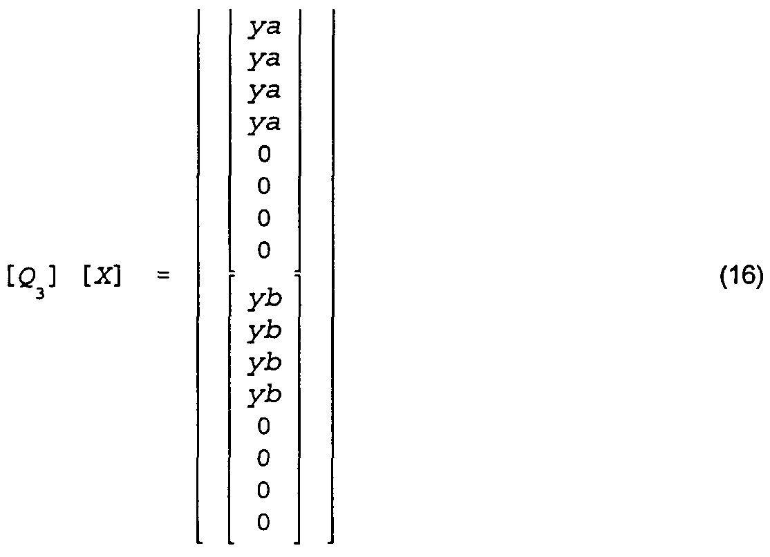
Thus, by applying the operator [Q3] , which is a 16x16
operator, to two vertical blocks of DCT coded
coefficients given by equation (1) , the following results
are produced:
The zero's on the right hand of equation (16) can be discarded so that only the ya's and yb's are retained.
The output, therefore, of applying the operator [Q3] to
two frame DCT coded blocks is separate top and bottom
field blocks for fields a and b, each separately filtered
and downsampled effectively using a 4x4 IDCT operating on
field DCT coded blocks.
Because [Q3] has the following form:
the operator [Q3] can be rewritten in the following form:
[p]
0, = (18) Cgl
where [p] and [q] are each 4x16 matrices. Accordingly,
the operator [Q3] becomes an 8x16 operator instead of a
16x16 operator so that, when it is applied to two frame
DCT coded blocks, only the ya's and yb's of equation (16)
results .
The following description shows how the
operator [Q3] may be used on two dimensional blocks having
eight columns, and also shows the horizontal IDCT with
filtering and downsampling. For a full two dimensional
field based 4x4 IDCT of frame DCT coded blocks, the [Q3]
operation is only performed vertically. A standard four
point IDCT is performed horizontally. Let X be a
macroblock consisting of four frame coded 8x8 DCT blocks
Xlf X2, X3, and X4. Spatially, these 8x8 DCT coded blocks
are oriented as follows:
X X
1 2
X X
3 4
As a first step, the high order horizontal coefficients
of each of the 8x8 DCT coded blocks X1; X2, X3, and X4 are
discarded (the four high order coefficients in each row)
so that each DCT block becomes an 8x4 block (X1 ' , X2 ' ,
X3 ' , and X4 ' ) . A 16x4 matrix [Xj may be used to define
the two 8x4 frame coded DCT blocks Xx ' and X3 ' according
to the following equation:
[X m] (19)
and similarly a 16x4 matrix [X may be used to define the
frame coded 8x4 DCT blocks X2 ' and X4 ' according to the
following equation:
At this point, the vertical operation can be performed
first, followed by the horizontal operation, or the
horizontal operation may be performed first followed by
the vertical operation. Assuming that the vertical
operation is performed first, field based DCT domain
vertical filtering and downsampling is performed
according to the following equation:
[G ] a
[G] - [03] [X ] (21)
where [G] is an 8x8 matrix, [Q3] is an 8x16 matrix, [Xj
is the 16x4 matrix described above, and [Ga] and [Gb] are
4x4 matrices for corresponding fields a and b. Then,
horizontal DCT domain filtering and downsampling is
performed according to the following equation:
[ya] [Ga] [T4] [yb] [Gb] (22)
where [ya] and [yb] are each a 4x4 matrix, where [Ga] and
[Gb] are the 4x4 matrices derived from equation (21) ,
where the ya and yb are the resulting residual or pixel
values provided by the IDCT module 102 to the adder 106,
and where [T4] is the four point DCT basis vector 4x4
matrix from equation (11) . These operations represented
by equations (21) and (22) are also applied thereafter to
the 16x4 array [X .
On the other hand, the order of the above
operations can be reversed in the case of first
performing horizontal downsampling, followed by vertical
downsampling with the same results. Thus, the four point
DCT basis vector matrix T4 is applied to the 8x4 array
[Xi1] and the 8x4 array [X3 ' ] according to the following
equations :
tx'l
[C ] [ T4] (23)
[x'l
[G ] [ T4] (24)
The results [G and [G2] can be combined according to the
following equation:
Thereafter, a vertical field based operation may be
performed according to the following equation:
[ya] [yb] = [03] [ G2] (26)
Figure 17 shows an exemplary hardware
implementation of an IDCT 300 which can be used for the
IDCT module 102 of Figure 10. The IDCT 300 processes
both field DCT and frame DCT coded macroblocks. The
output of the IDCT 300 is always a or b structured
pixels. For field DCT coded
blocks, the usual 4x4 IDCT is executed to achieve
horizontal and vertical filtering and downsampling. For
frame DCT coded blocks, the horizontal processing is the
same, but vertically the Q3 operator is used to
effectively convert the frame coding to field coding, and
then to filter and downsample each field separately. The
result is a or b structured field blocks in either case.
It is noted here that matrix multiplication is
not commutative (a*b does not in general equal b*a) .
Therefore, each matrix multiplier of the IDCT 300 has a
pre and a post input to indicate the order of the
associated matrix multiplication.
A macroblock X consisting of four 8x8 DCT
blocks Xlf X2, X3, and X4 is received by a parser 302 which
sends the DCT blocks along one path of the IDCT 300 if
the DCT blocks are field coded blocks and sends the DCT
blocks along a different path of the IDCT 300 if the DCT
blocks are frame coded blocks. If the four 8x8 DCT
blocks are field DCT coded blocks as signaled by a DCT
type input to the parser 302, each block is fed to a
discard module 304 which discards the high order
horizontal and vertical coefficients in order to form a
4x4 field DCT coded block for each of the 8x8 DCT field
coded blocks supplied to it . A matrix multiplier 306
executes a four point vertical IDCT on the columns of the
blocks provided to it. The vertically processed 4x4
blocks are fed to a selector 308. Because the DCT type
is field, the 4x4 blocks provided by the matrix
multiplier 306 are selected for output to a matrix
multiplier 310. The matrix multiplier 310 executes a
four point horizontal IDCT on each row of the blocks
supplied to it. The output of the matrix multiplier 310
is a 4x4 block of filtered and downsampled pixels for
field a or b.
If a macroblock X consists of frame DCT coded
blocks as signaled by the DCT type, the blocks of the
macroblock are fed in turn by the parser 302 to a discard
module 312 which discards the high order horizontal
coefficients in order to form corresponding 8x4 frame DCT
coded blocks . These 8x4 blocks Xx ' , X2 ' , X3 ' , and X4 ' are
provided to a reorder module 314 where these 8x4 blocks
are stored and reordered and then provided as two 16x4
blocks Xm (X-. 1 and X3 * ) and Xn (X2* and X4 ' ) . The 16x4
block Xra is first fed to a matrix multiplier 316 which,
using the Q3 operator, applies vertical conversion,
filtering, and downsampling to the field DCT
coefficients. The output of the matrix multiplier 316 is
an 8x4 block consisting of Ga and Gb . A store and delay
module 318 then separately outputs the 4x4 blocks Ga and
Gb to the selector 308. Because the current macroblock X
being processed is of type frame, the selector 308
applies the 4x4 Ga and Gb blocks to the matrix multiplier
310 which, operating first on the 4x4 block Ga, executes
a four point IDCT on each row of the block, and then
subsequently processes the 4x4 block Gb in a similar
fashion. The outputs of the matrix multiplier 310 are
4x4 blocks of filtered and downsampled pixels ya for the
a field and yb for the b field.
The IDCT module 102 can be modified in order to
permit the elimination of the interpolation module 108.
That is, the four point IDCT previously described
involves the use of four point DCT basis vectors (the
[T4] operator) on the four low order DCT coefficients
originally derived from an eight point DCT operation in
the encoder. This process results in the "in between"
downsampled pixel positioning as previously described and
as replicated in Figure 18. In order to permit the
elimination of the interpolation module 108, an
alternative operator [T4 ' ] can be derived.
Thus, instead of consisting of the four point
DCT basis vectors, the rows of the alternative operator
[T4 ' ] consist of downsampled eight point DCT basis
vectors. If each row of the alternative operator [T4']
contains the second sample, the fourth sample, the sixth
sample, and the eighth sample, respectively, of the four
low order eight point DCT basis vectors, and if the
decoder discards the four high order coefficients for
each block and performs a four point IDCT on the
remaining coefficients using the alternative operator
[T4 ' ] , then the spatial relationship between the original
pixels (x's) and the decoded pixels (y's) is shown in
Figure 19. Thus, if the [T4] operator is used to
downsample the A field, and the alternative operator [T4']
is used to downsample the B field, then the resulting
spatial relationship is shown in Figure 20. It is noted
that this is the desired relationship as shown by the
column 224 of Figure 16.
Therefore, it is desired to modify the IDCT
module 102 so that its output always has the a/b pixel
structure of Figure 20. For field coded macroblocks of
the A field, a four point IDCT (using the operator [T4] )
is performed, as before. But for field coded macroblocks
of the B field, the alternative operator [T4 ' ] derived
from the eight point basis vectors is used for IDCT.
For frame coded macroblocks, a modified
operator similar to the operator Q3 must be derived that
computes two separately downsampled fields directly from
the frame coded coefficients. The modified operator Q3 '
must incorporate the operator [T4] for the A field and
the alternative operator [T4 ' ] for the B field. The
operator [T4] is given by equation (11) and the operator
[P4] is given by equation (12) , where the DCT basis
vectors rOO, rOl, ..., r33 are four point DCT basis
vectors. The alternative operators [T4 ' ] and [P4 ' ] may
be given by the following equations :
tOl t03 t05 t07 0 0 0 0 til tl3 tl5 tl7 0 0 0 0 t21 t23 t25 t27 0 0 0 0 t31 t33 t35 t37 0 0 0 0
[P41] (28)
0 0 0 0 0 0 0 0
0 0 0 0 0 0 0 0
0 0 0 0 0 0 0 0
0 0 0 0 0 0 0 0
where the DCT basis vectors tOl, t03, t37 are eight
point DCT basis vectors. The alternative operator [P4 ' ]
does not need the V"2 scaling factor which is incorporated
into the operator [P4] because the alternative operator
[P4 ' ] uses eight point basis vectors. Accordingly, the
alternative operator [IP4'2] is given by the following
where the operator [IP4'2] is a filter/downsample/IDCT
operator which clearly operates differently on the A
field (using P4T) than on the B field (using P4,τ) .
A modified operator Q3 ' , therefore, is defined
according to the following equation:
[(?'] = [IP41 ] [ T ] [IT8 ]
3 2 f 2 (30)
This modified operator Q3 ' is used by the IDCT module 102
instead of the operator Q3 previously described. The IDCT
module 102 using these appropriate operators results in
an a/b pixel structure that eliminates the need for the
interpolation module 108.
As previously stated, the use of a prediction
upsampling filter should result in a close spatial domain
approximation to the effective filtering operation
performed by a 4x4 IDCT. Because the two fields are now
filtered differently using the 4x4 IDCT, the two fields
must be filtered differently by the motion compensator
104. The basic filter structure is the same for both
fields, only the tap values differ. The tap values for
both fields can easily be derived and stored in memory.
The following are representative values for the
matrices [T8} and [T4] :
[T8] = 0.3536 0.3536 0.3536 0.3536 0.3536 0.3536 0.3536 0.3536
0.4904 0.4157 0.2778 0.0975 -0.0975 -0.2778 -0.4157 -0.4904
0.4619 0.1913 -0.1913 -0.4619 -0.4619 -0.1913 0.1913 0.4619
0.4157 -0.0975 -0.4904 -0.2778 0.2778 0.4904 0.0975 -0.4157
0.3536 -0.3536 -0.3536 0.3536 0.3536 -0.3536 -0.3536 0.3536
0.2778 -0.4904 0.0975 0.4157 -0.4157 -0.0975 0.4904 -0.2778
0.1913 -0.4619 0.4619 -0.1913 -0.1913 0.4619 -0.4619 0.1913
0.0975 -0.2778 0.4157 -0.4904 0.4904 -0.4157 0.2778 -0.0975
[T4] =
0.5000 0.5000 0.5000 0.5000
0.6533 0.2706 -0.2706 -0.6533
0.5000 -0.5000 -0.5000 0.5000 0.2706 -0.6533 0.6533 -0.2706
However, it should be understood that these values are
merely exemplary and other values could be used.
Certain modifications of the present invention
have been discussed above. Other modifications will
occur to those practicing in the art of the present
invention. For example, according to the description
above, the interpolation module 108 can be eliminated
through derivation of an alternative operator [T4 ' ] .
Accordingly, the description of the present
invention is to be construed as illustrative only and is
for the purpose of teaching those skilled in the art the
best mode of carrying out the invention. The details may
be varied substantially without departing from the spirit
of the invention, and the exclusive use of all
modifications which are within the scope of the appended
claims is reserved.