US9986556B1 - Enhanced TTI bundling in TDD mode - Google Patents
Enhanced TTI bundling in TDD mode Download PDFInfo
- Publication number
- US9986556B1 US9986556B1 US14/265,099 US201414265099A US9986556B1 US 9986556 B1 US9986556 B1 US 9986556B1 US 201414265099 A US201414265099 A US 201414265099A US 9986556 B1 US9986556 B1 US 9986556B1
- Authority
- US
- United States
- Prior art keywords
- subframes
- data
- base station
- receiver
- transmitter
- Prior art date
- Legal status (The legal status is an assumption and is not a legal conclusion. Google has not performed a legal analysis and makes no representation as to the accuracy of the status listed.)
- Active, expires
Links
Images


Classifications
-
- H—ELECTRICITY
- H04—ELECTRIC COMMUNICATION TECHNIQUE
- H04W—WIRELESS COMMUNICATION NETWORKS
- H04W72/00—Local resource management
- H04W72/04—Wireless resource allocation
- H04W72/044—Wireless resource allocation based on the type of the allocated resource
- H04W72/0446—Resources in time domain, e.g. slots or frames
-
- H—ELECTRICITY
- H04—ELECTRIC COMMUNICATION TECHNIQUE
- H04B—TRANSMISSION
- H04B7/00—Radio transmission systems, i.e. using radiation field
- H04B7/24—Radio transmission systems, i.e. using radiation field for communication between two or more posts
- H04B7/26—Radio transmission systems, i.e. using radiation field for communication between two or more posts at least one of which is mobile
- H04B7/2643—Radio transmission systems, i.e. using radiation field for communication between two or more posts at least one of which is mobile using time-division multiple access [TDMA]
- H04B7/2656—Radio transmission systems, i.e. using radiation field for communication between two or more posts at least one of which is mobile using time-division multiple access [TDMA] for structure of frame, burst
Definitions
- the data when data that is transmitted by a transmitting entity to a receiving entity is not received by the receiving entity, or is received by the receiving entity with one or more errors, the data may be re-transmitted.
- the re-transmission of data could occur either automatically or in response to feedback from the receiving entity.
- LTE Long Term Evolution
- HARQ Hybrid Automatic Repeat Request
- the transmitting entity waits to receive a HARQ response from the receiving entity. If the transmitting entity receives a positive acknowledgement (ACK) as the HARQ response, then no re-transmission is needed and the transmitting entity can transmit additional data.
- ACK positive acknowledgement
- the transmitting entity If the transmitting entity receives a negative acknowledgement (NACK) as the HARQ response, then the transmitting entity re-transmits the data.
- NACK negative acknowledgement
- the transmitting entity may also re-transmit the data if the transmitting entity does not receive any HARQ response within a certain period of time.
- This re-transmission approach can allow data to be successfully transmitted from a transmitting entity to a receiving entity even when there is a substantial probability that the transmitted data will be received with one or more errors, for example, because of poor radio frequency (RF) conditions.
- the data can be re-transmitted multiple times until the data is received without errors.
- This re-transmission approach also increases latency. For example, there can be a period of delay between when the transmitting entity transmits data and when the transmitting entity receives a NACK response from the receiving entity and another period of delay between when the transmitting entity receives the NACK response and when the transmitting entity begins re-transmitting the data.
- LTE supports a bundling option for data transmissions by a user equipment (UE) device in the Physical Uplink Shared Channel (PUSCH).
- UE user equipment
- PUSCH Physical Uplink Shared Channel
- a UE device transmits data in one transmission time interval (TTI), which corresponds to a 1 millisecond (ms) subframe, and then waits to receive a HARQ response before re-transmitting the data or transmitting additional data.
- TTI bundling the UE device transmits the same data four times in four consecutive TTIs and then waits to receive a HARQ response. In this way, the UE device can transmit four instances of the same data, which allows for more robust reception of the data, but without the delay that would be associated with the UE device transmitting the data four times and waiting for a HARQ response after each transmission.
- An LTE system may use time division duplexing (TDD) for wireless communications between base stations and UE devices.
- TDD time division duplexing
- certain subframes are reserved for uplink communications and certain subframes are reserved for downlink communications.
- a TDD configuration may be unable to support conventional TTI bundling in which four consecutive TTIs are used to transmit the same data four times.
- some TDD configurations may have fewer than four consecutive subframes reserved for uplink communications.
- Described herein are methods and systems that can provide enhanced TTI bundling for TDD configurations.
- the number of transmissions of the same data can be made variable.
- the transmissions need not occur in consecutive subframes.
- Example embodiments provide a method for wireless communication in a wireless network using a TDD configuration.
- the TDD configuration specifies alternating time periods for uplink communications and downlink communications, in which a time period for uplink communications has U consecutive subframes and a time period for downlink communications has D consecutive subframes, wherein U ⁇ 1 and D ⁇ 1.
- the method involves: (a) identifying, by a transmitter, data to be transmitted to a receiver using TTI bundling; (b) obtaining, by the transmitter, a bundle size, N, to use for the TTI bundling, wherein N>1; (c) determining, by the transmitter, a number of consecutive subframes, C, available to transmit the data to the receiver; (d) performing, by the transmitter, a comparison of N to C; (e) selecting, by the transmitter, based on the comparison of N to C, a set of N subframes for N transmissions of the data to the receiver; and (f) transmitting, by the transmitter, the data N times to the receiver, using the set of N subframes.
- Example embodiments also provide an apparatus.
- the apparatus comprises a transceiver for transmitting and receiving wireless communications according to a TDD configuration.
- the TDD configuration specifies alternating time periods for uplink communications and downlink communications, in which a time period for uplink communications has U consecutive subframes and a period for downlink communications has D consecutive subframes, wherein U ⁇ 1 and D ⁇ 1.
- the apparatus further comprises: a processor; data storage; and program instructions stored in the data storage and executable by the processor to cause the apparatus to perform functions.
- the functions comprise: (a) identifying data to be transmitted to a receiver using TTI bundling; (b) obtaining a bundle size, N, to use for the TTI bundling, wherein N>1; (c) determining a number of consecutive subframes, C, available to transmit the data to the receiver; (d) performing a comparison of N to C; (e) selecting, based on the comparison of N to C, a set of N subframes for N transmissions of data to the receiver; and (f) transmitting, via the transceiver, the data N times to the receiver using the set of N subframes.
- FIG. 1 is a block diagram of a communication system, in accordance with an example embodiment.
- FIG. 2A is a conceptual illustration of a division of uplink resources into resource blocks, in accordance with an example embodiment.
- FIG. 2B is a conceptual illustration of two time-consecutive resource blocks, in accordance with an example embodiment.
- FIG. 3 is a flow chart of a method for uplink TTI bundling, in accordance with an example embodiment.
- FIG. 4 is a flow chart of a method for downlink TTI bundling, in accordance with an example embodiment.
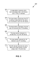
- FIG. 5 is a flow chart of a method in which a transmitter selects a set of N subframes to transmit data using TTI bundling, in accordance with an example embodiment.
- FIG. 6 illustrates a sequence of subframes used for uplink TTI bundling in a TDD configuration, in accordance with an example embodiment.
- FIG. 7 illustrates a sequence of subframes used for uplink TTI bundling in a TDD configuration, in accordance with an example embodiment.
- FIG. 8 illustrates a sequence of subframes used for downlink TTI bundling in a TDD configuration, in accordance with an example embodiment.
- FIG. 9 illustrates a sequence of subframes used for downlink TTI bundling in a TDD configuration, in accordance with an example embodiment.
- FIG. 10 is a block diagram of an apparatus, in accordance with an example embodiment.
- the enhanced TTI bundling could be used by a UE device transmitting data in an uplink shared channel (e.g., a PUSCH channel).
- the enhanced TTI bundling could also be used for a base station transmitting data in a downlink shared channel (e.g., a PDSCH channel).
- the bundle size can be variable.
- a base station may determine a TTI bundle size for a particular UE device and then indicate to the UE device what bundle size to use for the TTI bundling.
- the base station could determine the TTI bundle size based on one or more uplink parameters, such as a signal-plus-interference-to-noise ratio (SINR) of the UE's signal at the base station, a delay budget for the UE's data or other quality of service (QoS) considerations, and/or utilization of the uplink shared channel.
- SINR signal-plus-interference-to-noise ratio
- QoS quality of service
- the bundle size that is determined in this way could be four (as with convention TTI bundling), or less than four (e.g., if the SINR is relatively high or to conserve resources if the utilization is high). In addition, some implementations could support a bundle size that is greater than four.
- a base station may determine a TTI bundle size to use when transmitting data to a UE device using TTI bundling.
- the base station may determine the TTI bundle size based on one or more downlink parameters, such as a SINR of the base station's signal at the UE device (which the UE device may report to the base station), a delay budget for the base station's data or other QoS considerations, and utilization of the downlink shared channel.
- the multiple transmissions of the same data need not occur in consecutive subframes.
- This aspect can be particularly useful for TDD configurations that have fewer than four consecutive uplink subframes, in the case of TTI bundling by a UE device, or TDD configurations that have fewer than four consecutive downlink subframes, in the case of TTI bundling by a base station.
- LTE defines seven different TDD configurations, identified as “TDD configuration 0” through “TDD configuration 6,” each having a different respective sequence of uplink subframes, downlink subframes, and special subframes. See Table 4.2-2 in 3 rd Generation Partnership Project, TS 36.211, V12.0.0 (2013-12), hereinafter “3GPP specification.” These TDD configurations are summarized below in Table 1.
- a “U” indicates an uplink subframe, i.e., a subframe that is reserved for uplink communications
- a “D” indicates a downlink subframe, i.e., a subframe that is reserved for downlink communications
- an “S” indicates a special subframes.
- a special subframe allows time for switching from downlink communications to uplink communications.
- a special subframe consists of three fields: a Downlink Pilot Time Slot (DwPTS), a Guard Period (GP) and an Uplink Pilot Time Slot (UpPTS).
- the DwPTS is a shortened downlink subframe with 3/9/10/11/12 OFDM symbols, which could be used for downlink communications.
- none of the TDD configurations in the above-referenced 3GPP specification has more than three consecutive uplink subframes.
- conventional TTI bundling in which the same data is transmitted in four consecutive subframes, is not available for uplink communications.
- the two aforementioned aspects of the enhanced TTI bundling approaches described can allow for TTI bundling to be used with such TDD configurations.
- the bundle size is variable, it is possible for a bundle size less than four to be selected.
- the smaller bundle size might allow the transmissions to occur in consecutive subframes. For example, if the bundle size is three, a UE device could use TTI bundling with TDD configuration 0 by transmitting the same data in three consecutive uplink subframes (e.g., subframes 2, 3, and 4).
- the enhanced TTI bundling approaches described herein allow for non-consecutive subframes to be used. For example, if the bundle size is four, a UE device could use TTI bundling with TDD configuration 0 by transmitting the same data in three consecutive uplink subframes (e.g., subframes 2, 3, and 4) and one additional uplink subframe (e.g., subframe 7).
- the transmitter of the data using TTI bundling may determine whether to use consecutive subframes or non-consecutive subframes. For example, the transmitter may compare the bundle size, N, with the number of consecutive subframes, C, available to transmit the data. N could be determined based on various parameters, as described herein. C is based on the particular TDD configuration being used. If N ⁇ C, then the transmitter may use N consecutive subframes. If N>C, then the transmitter may use C consecutive subframes and one or more additional subframes (e.g., N ⁇ C subframes).
- FIG. 1 is a block diagram of a communication system 10 in which exemplary embodiments may be employed.
- Communication system 10 includes a radio access network (RAN) 12 that includes one or more entities that can communicate over an air interface, as exemplified by base station (BS) 14 .
- RAN 12 could also include one or more control entities, such as a base station controller (BSC) or radio network controller (RNC).
- BSC base station controller
- RNC radio network controller
- BS 14 could be, for example, a base transceiver station, a wireless access point, an access node, a Node-B, or an eNodeB.
- FIG. 1 shows only one base station in RAN 12 , it is to be understood that RAN 12 could include any number of base stations.
- BS 14 radiates to define one or more wireless coverage areas within which BS 14 can wirelessly communicate with UE devices.
- the wireless coverage area defined by BS 14 could be a cell that generally surrounds BS 14 .
- BS 14 may define multiple wireless coverage areas, such as sectors. Each sector may be defined by multiple antennas in BS 14 so as to generally correspond to a range of azimuthal angles (e.g., 120°) about BS 14 .
- BS 14 is shown as being in wireless communication with UEs 16 , 18 , and 20 via respective air interfaces 22 , 24 , and 26 .
- UEs 16 , 18 , and 20 could be wireless telephones, wireless handheld, tablet, or laptop computers, or other types of wireless communication devices.
- FIG. 1 shows BS 14 in wireless communication with three UEs, it is to be understood that BS 14 could be in wireless communication with a greater or fewer number of UEs.
- the number of UEs in wireless communication with BS 14 can change over time, for example, as a result of one or more UEs moving into or out of the wireless coverage area of BS 14 and/or as a result of one or more UEs beginning or ending communication sessions.
- Air interfaces 22 , 24 , and 26 could use a TDD configuration that specifies alternating time periods for uplink communications and downlink communications, in which a time period for uplink communications has U consecutive subframes and a time period for downlink communications has D consecutive subframes, and wherein U ⁇ 1 and D ⁇ 1.
- the TDD configuration used by air interfaces 22 , 24 , and 26 could be, for example, one of the TDD configurations shown above in Table 1.
- the communications over air interfaces 22 , 24 , and 26 will be described herein with respect to the LTE protocol. It is to be understood, however, that other wireless communication protocols could be used.
- RAN 12 may provide access to one or more transport networks 28 , which could include, for example, the public switched telephone network (PSTN) and/or the Internet or other packet-switched networks.
- PSTN public switched telephone network
- a UE device being served by BS 14 may engage in a communication session, via RAN 12 , with an endpoint connected to one of transport networks 28 .
- the endpoint could be, for example, another UE device, a landline telephone, an email server, Web server, media server, or gaming server.
- the communication session could involve voice, text, images, video, data, or other media that is transferred from the UE device to the endpoint and/or from the endpoint to the UE device.
- the UE may transmit data over an uplink channel to BS 14 and may receive data from BS 14 over a downlink channel.
- the communication session could be one that involves a user of the UE device, such as a voice communication application or Web browsing application.
- the communication session could involve a background task, such as periodically registering with wireless network 12 .
- UEs 16 , 18 , and 20 may transmit data to BS 14 over an uplink shared channel. The usage of the uplink shared channel may be controlled by BS 14 or by some other entity in wireless network 12 .
- the LTE protocol defines a Physical Uplink Shared Channel (PUSCH) that UEs can use to transmit data to a base station and a Physical Downlink Shard Channel (PDSCH) that the base station can used to transmit data to the UEs. Portions of the PUSCH and the PDSCH may be allocated to particular UEs by allocating resource blocks.
- FIG. 2A illustrates how the uplink resources and the downlink resources in a given wireless coverage area may be divided in time and frequency domains into resource blocks.
- OFDM orthogonal frequency division multiplexing
- Each OFDM symbol is formed from a plurality of sub-carriers, typically 12 sub-carriers, each with a bandwidth of 15 kHz.
- a resource block corresponds to a plurality of sub-carriers that are used to form an OFDM symbol and has a duration that can accommodate a particular number of OFDM symbols.
- each resource block typically occupies a 0.5 ms slot of time.
- FIG. 2A shows resource blocks 100 - 110 for a particular slot.
- each of resource blocks 100 - 110 occupies a respective portion of frequency bandwidth, typically 180 kHz in LTE implementations.
- FIG. 2A shows six resource blocks in each slot, a wireless coverage area could have a greater number of resource blocks, as indicated by the dots above and below resource blocks 100 - 110 .
- FIG. 2A also includes a more detailed view of resource block 108 .
- This detailed view shows that the 180 kHz of frequency bandwidth corresponds to 12 sub-carriers of 15 kHz each. Further, in this example, the 0.5 ms slot of time corresponds to the duration of seven OFDM symbols. In other examples, a 0.5 ms slot could correspond to a different number of OFDM symbols.
- a resource block may be described as a set of resource elements, with each resource element corresponding to one modulated sub-carrier in an OFDM symbol.
- the detailed view of uplink resource block 108 in FIG. 2A shows the division of the resource block into multiple resource elements, such as resource element 108 a.
- One or more uplink resource blocks may be allocated to a particular UE device to transmit data in the uplink shared channel (PUSCH). For example, resource blocks 100 and 102 might be allocated to UE 16 , resource blocks 104 - 108 might be allocated to UE 18 , and resource block 110 might be allocated to UE 20 .
- the allocation of resource blocks to UEs could be made by BS 14 or by some other entity in wireless network 12 .
- one or more downlink resource blocks could be allocated to a particular UE device to receive data that is transmitted by the base station in the downlink shared channel (PDSCH).
- PDSCH downlink shared channel
- FIG. 2B illustrates an uplink resource allocation for a UE that is maintained for two consecutive slots of time (Slot 0 and Slot 1) in a given subframe (a downlink resource allocation may be similar).
- the two consecutive slots of time are treated as a transmission time interval (TTI) for purposes of LTE's HARQ process.
- TTI transmission time interval
- the UE waits to receive a HARQ response from the RAN to determine whether the data should be re-transmitted or whether the UE can transmit additional data. If the HARQ response is an ACK, indicating that the data was successfully received, then the UE can transmit additional data.
- the UE re-transmits the data.
- the UE may also re-transmit the data if the UE does not receive a HARQ response within a predetermined period of time.
- the UE may transmit the same data in multiple TTIs before waiting for a HARQ response.
- the TTI bundle size is the number of TTIs that the UE uses to transmit the data.
- a TTI bundle size of N means that the UE transmits the same data N times before waiting for a HARQ response.
- FIGS. 3-5 are flow charts illustrating example methods relating to TTI bundling.
- FIG. 3 illustrates an example method of implementing TTI bundling for uplink communications.
- FIG. 4 illustrates an example method of implementing TTI bundling for downlink communications.
- FIG. 5 illustrates an example method of selecting a set of N subframes to use for TTI bundling (on either the uplink or the downlink).
- the example methods are described with reference to a communication system as shown in FIG. 1 , air interface resources as shown in FIGS. 2A and 2B , and TDD configurations as shown in Table 1. It is to be understood, however, that the methods could be applied to other types of communication systems, air interface resources, and/or TDD configurations.
- FIG. 3 is a flowchart illustrating an example method 200 for implementing TTI bundling for uplink communications from a UE device (e.g., UE device 16 ) to a base station (e.g., base station 14 ).
- the base station receives uplink communications from the UE device over a TDD air interface (e.g., air interface 22 ), as indicated by block 202 .
- the TDD air interface could, for example, have one of the configurations set forth in Table 1.
- the uplink communications could include voice, video, or other data and could be associated with a bearer that has a predefined quality of service (QoS).
- QoS quality of service
- the UE device could use a bearer with a guaranteed bit rate to transmit voice.
- the UE device could use a bearer with a non-guaranteed bit rate for Web browsing. Other examples are possible as well.
- the base station determines that TTI bundling is warranted for the uplink communications from the UE device, as indicated by block 204 .
- the base station may determine whether TTI bundling is warranted for the UE device based on at least a power headroom report that is received from the UE device.
- a UE device may calculate a “power headroom” as a difference between the UE device's transmit power requirement for its uplink resource allocation and the UE device's maximum transmit power. If the power headroom that a UE device reports is positive, indicating that the UE device's transmit power requirement is less than its maximum transmit power, then the base station may conclude that TTI bundling is not warranted for the UE device.
- the base station may determine that TTI bundling is warranted for the UE device. Other methods for determining whether TTI bundling is warranted could be used as well.
- the base station calculates a bundle size, N, to use for the TTI bundling, as indicated by block 206 .
- the base station may calculate N as a function of one or more uplink TTI bundling parameters.
- SINR signal-plus-interference-to-noise ratio
- the base station could determine P 1 (SINR) based on one or more measurements at the base station of signals transmitted by the UE device.
- the base station may periodically measure the SINR of the UE's signals, and the base station could then determine P 1 based on one or more of those SINR measurements.
- the base station may measure the SINR of a signal transmitted by the UE device in response to determining that TTI bundling is warranted.
- F could decrease as a function of increasing P 1 (SINR).
- a higher SINR could indicate a higher link quality between the UE device and base station, such that a smaller bundle size, N, may be sufficient.
- the base station may determine P 2 (delay budget) based on the type of bearer being used by the UE device for the uplink communications. For example, a guaranteed bit rate bearer may have a relatively low delay budget, whereas a non-guaranteed bit rate bearer may have a relatively high delay budget. In example embodiments, F could decrease as a function of decreasing P 2 (delay budget). In this regard, a lower delay budget may indicate a lower tolerance for delay, such that a smaller bundle size, N, may be beneficial in order to cause less transmission latency.
- the base station may determine P 3 (utilization) based on how many of the uplink resource blocks that could be allocated by the base station to UE devices have already been allocated. In example embodiments, F could decrease as a function of increasing P 3 (utilization).
- uplink TTI bundling typically increases the utilization of the uplink shared channel. Thus, if the uplink shared channel is already heavily utilized, it may be beneficial for the base station to select a smaller TTI bundle size, N, in order to conserve resources.
- F may map the uplink TTI bundling parameters (P 1 , P 2 , P 3 ) to one of a plurality of values of N.
- F may provide for a greater or fewer number of values of N and/or may allow N to be greater than 4. It is also to be understood that the particular set of three TTI bundling parameters given in equation (1) is meant to be exemplary only. N could alternatively be calculated based on additional and/or different parameters.
- the base station indicates the bundle size, N, to the UE device, as indicated by block 208 .
- the base also instructs the UE device to use TTI bundling, as indicated by block 210 .
- the UE transmits the same data to the base station N times, using a set of N subframes, as indicated by block 212 .
- the UE device may select the set of N subframes, for example, as described below with reference to FIG. 5 .
- FIG. 3 shows steps of method 200 being performed in a particular order, it is to be understood that some of these steps could be performed in a different order and/or some of the steps could be omitted or combined.
- FIG. 3 shows the base station calculating N (block 206 ) as occurring after the base station determines that TTI bundling is warranted (block 204 ).
- the base station may periodically calculate a value of N for a UE device being served by the base station. The periodic calculations may occur before a determination that TTI bundling is warranted for the UE device, and the periodic calculations may continue after TTI bundling has been implemented. In this way, the base station may calculate different values of N as conditions change.
- the base station may periodically indicate to the UE device the calculated value of N. In this way, when the base station subsequently determines that TTI bundling is warranted for the UE device, and instructs the UE device to use TTI bundling, the UE device may use the bundle size, N, that was previously indicated by the base station.
- FIG. 4 is a flowchart illustrating an example method 300 for implementing TTI bundling for downlink communications from a base station (e.g., base station 14 ) to a UE device (e.g., UE device 16 ).
- the base station transmits downlink communications to the UE device over a TDD air interface (e.g., air interface 22 ), as indicated by block 302 .
- the TDD air interface could, for example, have one of the configurations set forth in Table 1.
- the downlink communications could include voice, video, or other data and could be associated with a bearer that has a predefined QoS.
- the base station determines that TTI bundling is warranted for the downlink communications to the UE device, as indicated by block 304 .
- the base station may make this determination, for example, based on an indication from the UE device that the downlink channel quality has degraded.
- the UE device may measure a signal transmitted by the base station and report one or more parameters relating to the signal strength or signal quality.
- Such parameters may include, for example, a reference signal received power (RSRP), a reference signal received quality (RSRQ), and/or a signal-plus-interference-plus-noise ratio (SINR).
- RSRP reference signal received power
- RSRQ reference signal received quality
- SINR signal-plus-interference-plus-noise ratio
- the base station calculates a bundle size, N, to use for the TTI bundling, as indicated by block 306 .
- the base station may calculate N as a function of one or more downlink TTI bundling parameters.
- SINR signal-plus-interference-to-noise ratio
- the base station could determine Q 1 (SINR) based on one or more measurements reported by UE device. For example, the UE device may periodically measure and report the SINR of the base station's signals. The base station could then determine Q 1 based on one or more of those SINR measurements. Alternatively or additionally, the UE device may measure the SINR of the base station's signal in response to an instruction from the base station. The base station may send such an instruction, for example, in response to determining that TTI bundling is warranted. In example embodiments, G could decrease as a function of increasing Q 1 (SINR). In this regard, a higher SINR could indicate a higher link quality between the base station and UE device, such that a smaller bundle size, N, may be sufficient.
- Q 1 SINR
- the base station may determine Q 2 (delay budget) based on the type of bearer being used for the downlink communications to the UE device. For example, a guaranteed bit rate bearer may have a relatively low delay budget, whereas a non-guaranteed bit rate bearer may have a relatively high delay budget.
- G could decrease as a function of decreasing Q 2 (delay budget).
- a lower delay budget may indicate a lower tolerance for delay, such that a smaller bundle size, N, may be beneficial in order to cause less transmission latency.
- the base station may determine Q 3 (utilization) based on how many of the downlink resource blocks that could be allocated by the base station to UE devices have already been allocated.
- G could decrease as a function of increasing P 3 (utilization).
- downlink TTI bundling typically increases the utilization of the downlink shared channel.
- N TTI bundle size
- G may map the downlink TTI bundling parameters (Q 1 , Q 2 , Q 3 ) to one of a plurality of values of N.
- G may provide for a greater or fewer number of values of N and/or may allow N to be greater than 4. It is also to be understood that the particular set of three TTI bundling parameters given in equation (2) is meant to be exemplary only. N could alternatively be calculated based on additional and/or different parameters.
- the base station transmits the same data to the UE device N times, using a set of N subframes, as indicated by block 308 .
- the base station may select the set of N subframes, for example, as disclosed below for FIG. 5 .
- FIG. 4 shows steps of method 300 being performed in a particular order, it is to be understood that some of these steps could be performed in a different order and/or some of the steps could be omitted or combined.
- FIG. 4 shows the base station calculating N (block 306 ) as occurring after the base station determines that TTI bundling is warranted (block 304 ).
- the base station may periodically calculate a value of N for a UE device being served by the base station. The periodic calculations may occur before a determination that TTI bundling is warranted for the downlink communications to the UE device, and the periodic calculations may continue after TTI bundling has been implemented. In this way, the base station may calculate different values of N as conditions change.
- FIG. 5 illustrates an example method 400 that shows how a set of N subframes may be selected for transmitting data using TTI bundling.
- Method 400 refers to functions that are performed by a transmitter in relation to data that is to be transmitted from the transmitter to a receiver.
- the transmitter could be a UE device and the receiver could be a base station, in which case method 400 may be performed in conjunction with method 200 shown in FIG. 3 .
- the transmitter could be a base station and the receiver could be a UE device, in which case method 400 may be performed in conjunction with method 300 shown in FIG. 4 .
- Method 400 may begin with identifying, by the transmitter, data to be transmitted to the receiver using TTI bundling, as indicated by block 402 .
- TTI bundling is warranted for the transmitter.
- the decision that TTI bundling is warranted is made by a base station, for both downlink communications from the base station to a UE device and for uplink communications from a UE device to the base station.
- the data to be transmitted to the base station using TTI bundling may be identified after the UE device has received an instruction from the base station to use TTI bundling.
- Method 400 may then proceed with obtaining, by the transmitter, a bundle size, N, for the TTI bundling, as indicated by block 404 .
- the bundle size, N could be obtained by the UE device from the base station.
- the base station may calculate N, such as by using equation (1) described above, and transmit an indication of the value of N.
- the base station may periodically calculate a value of N for a UE device and indicate the calculated value of N to the UE device.
- the base station may indicate the value of N when instructing the UE device to use TTI bundling.
- the bundle size, N may be obtained by the base station calculating N, such as by using equation (2) described above.
- Method 400 may also involve determining, by the transmitter, a number of consecutive subframes, C, available to transmit the data to the receiver, as indicated by block 406 .
- the transmitter may determine C based on the TDD configuration that is currently being used. In the case that the transmitter is a UE device, C may be the number of consecutive uplink subframes in the TDD configuration. In the case that the transmitter is a base station, C may be the number of consecutive downlink subframes in the TDD configuration. In some implementations, however, a base station may be able to use special subframes for downlink communications. Thus, in the case that the transmitter is a base station, C may be a number of consecutive subframes that includes one or more downlink subframes and one or more special subframes.
- method 400 may proceed with performing, by the transmitter, a comparison of N to C, as indicated by block 408 .
- the comparison may, for example, involve determining whether N is less than C, equal to C, or greater than C.
- Method 400 may then involve selecting, by the transmitter, based on the comparison of N to C, a set of N subframes for the N transmissions of the data to the receiver, as indicated by block 410 .
- the N subframes in the set are N consecutive frames, as indicated by block 412 .
- the set of N subframes includes C consecutive subframes and at least one additional subframe, as indicated by block 414 .
- the at least one additional subframe is separated from the C consecutive subframe by one or more subframes that are not in the set of N subframes.
- Method 400 may conclude with transmitting, by the transmitter, the data N times to the receiver, using the set of N subframes.
- the UE device may transmit the data N times to the base station using a set of N subframes (i.e., uplink subframes), with each transmission of data occurring in one of the subframes in the set.
- the base station may transmit the data N times to the UE device using a set of N subframes (i.e., either downlink subframes or a combination of downlink and special subframes), with each transmission of data occurring in one of the subframes in the set.
- FIGS. 6 and 7 illustrate subframes that may be used by a UE device to transmit data to a base station, using TTI bundling with different bundle sizes.
- FIGS. 8 and 9 illustrate subframes that may be used by a base station to transmit data to a UE device, using TTI bundling with different bundle sizes.
- FIGS. 6-9 each illustrate a single frame having 10 subframes, in which the subframes are labeled “0” through “9.” Uplink subframes are labeled “U,” downlink subframes are labeled “D,” and special subframes are labeled “S.”
- the subframes used to transmit data using TTI bundling are indicated by shading and are further labeled “T1,” “T2,” etc.
- FIGS. 6 and 7 illustrate examples in which a UE device transmits data using TTI bundling with an air interface in TDD configuration 0.
- TDD configuration 0 has three consecutive uplink subframes.
- C 3 in these examples.
- the 3 consecutive uplink frames could be, for example, subframes 2, 3, and 4, as indicated in FIG. 6 .
- the UE device would transmit the data a first time (transmission T1) in subframe 2, transmit the data a second time (transmission T2) in subframe 3, and transmit the data a third time (transmission T3) in subframe 4.
- TDD configuration 0 also has another group of 3 consecutive uplink subframes: subframes 7, 8, and 9.
- a UE device may use either subframes 2, 3, and 4 or subframes 7, 8, and 9 to transmit the data.
- the UE device selects a set of 4 uplink subframes to transmit the data.
- the subframes in the set are not all consecutive.
- the set of 4 subframes may include 3 consecutive uplink subframes (e.g., subframes 2, 3, and 4) and another uplink subframe (e.g., subframe 7) that is separate from the 3 consecutive uplink frames.
- the UE device would transmit the data a first time (transmission T1) in subframe 2, transmit the data a second time (transmission T2) in subframe 3, transmit the data a third time (transmission T3) in subframe 4, and transmit the data a fourth time (transmission T4) in subframe 7.
- transmission T1 transmission time
- second time transmission T2
- third time transmission T3
- fourth time transmission T4
- subframe 7 7
- a UE device may use subframes 7, 8, and 9 in one frame and subframe 2 in the next frame to transmit the data. Other examples are possible as well.
- FIGS. 8 and 9 illustrate examples in which a base station transmits data to a UE device using TTI bundling with an air interface in TDD configuration 1.
- TDD configuration 1 has two consecutive downlink subframes.
- the base station is able to use special subframes to transmit data to the UE device.
- the special subframes are grouped together with the downlink subframes to provide a total of three consecutive subframes that the base station can use to transmit data.
- C 3 in these examples.
- the 3 consecutive frames could be, for example, subframes 4, 5, and 6, as indicated in FIG. 8 .
- the base would transmit the data a first time (transmission T1) in subframe 4, transmit the data a second time (transmission T2) in subframe 5, and transmit the data a third time (transmission T3) in subframe 6.
- T1 transmission
- T2 transmit the data a second time
- transmission T3 transmission time
- the base station may use subframe 9 in one frame and subframes 0 and 1 in the next frame to transmit the data.
- the base station selects a set of 4 subframes to transmit the data.
- the subframes in the set are not all consecutive.
- the set of 4 subframes may include 3 consecutive subframes (e.g., subframes 4, 5, and 6) and another subframe (e.g., subframe 9) that is separate from the 3 consecutive frames.
- the base station would transmit the data a first time (transmission T1) in subframe 4, transmit the data a second time (transmission T2) in subframe 5, transmit the data a third time (transmission T3) in subframe 6, and transmit the data a fourth time (transmission T4) in subframe 9.
- T1 transmission
- T2 transmit the data a second time
- transmission T3 transmit the data a third time
- T4 time transmission T4 in subframe 9.
- this particular selection of subframes is only one possible example.
- a UE device may use subframe 9 in one frame and subframes 0, 1, and 4 in the next frame to transmit
- FIG. 10 illustrates an example apparatus 500 , which could correspond to either a base station or a UE device, for example, as described above in relation to any of FIGS. 1-9 .
- Apparatus 500 includes a transceiver 502 that can transmit and receive wireless communications via one or more antennas, exemplified by antenna 504 .
- the wireless communications may include uplink communications in an uplink shared channel and downlink communications in a downlink shared channel.
- the uplink and downlink shared channels may each be divided in time and frequency domains into a plurality of resource blocks, for example, as described above in relation to FIGS. 2A and 2B .
- the uplink and downlink communications may occur during alternating time periods, for example, in accordance with a TDD configuration shown in Table 1.
- the TDD configuration may specify that a time period for uplink communications has U consecutive subframes and a time period for downlink communications has D consecutive subframes, wherein U ⁇ 1 and D ⁇ 1.
- the wireless communications transmitted and/or received by transceiver 502 may include voice, video, or other data. At least some of the data transmitted or received transceiver 502 may relate to data that is input into apparatus 500 or data that is output from apparatus 500 via one or more interfaces.
- apparatus 500 may include a user interface 506 .
- User interface 506 may include a display configured to convey textual, graphical, or other visual information to a user of apparatus 500 .
- User interface 506 may also include a touch screen, keyboard, buttons, and/or other means configured to receive input from a user of apparatus 500 .
- User interface 506 may further include audio input and output means, such as a microphone to receive voice or other audio from a user of apparatus 500 and a speaker to convey voice or other audio to the user.
- apparatus 500 may include a network interface 508 .
- Apparatus 500 may use network interface 508 to communicate with one or more entities, such as entities in RAN 12 , via wired or wireless connections.
- controller 510 may be coupled to other elements of apparatus, such as transceiver 502 , user interface 506 , and/or network 508 .
- Controller 510 could be implemented using hardware, software, and/or firmware.
- controller 510 includes a processor 512 and data storage 514 .
- Data storage 514 may include any type of non-transitory computer readable medium, such as random access memory (RAM), read-only memory (ROM), flash memory, cache memory, one or more magnetically encoded disks, one or more optically encoded disks, and/or any other type of volatile or non-volatile memory.
- Data storage 514 may store instructions 516 and data 518 .
- Instructions 516 could be executable program instructions that, when executed by processor 512 , cause apparatus 500 to perform functions, such as any of the functions described herein.
- Data 518 may include, for example, values of N and C, data used to determine bundle sizes, and/or any other type of data that may be generated or used by controller 510 .
- controller 510 may be configured (e.g., by instructions 516 stored in data storage 514 and executable by processor 512 ) to perform the following functions: (a) identifying data to be transmitted to a receiver using TTI bundling; (b) obtaining a bundle size, N, to use for the TTI bundling (e.g., by receiving an indication of N from a base station or by calculating N), wherein N>1; (c) determining a number of consecutive subframes, C, available to transmit the data to the receiver; (d) performing a comparison of N to C; (e) selecting, based on the comparison of N to C, a set of N subframes for N transmissions of data to the receiver; and (f) transmitting, via the transceiver 502 , the data N times to the receiver using the set of N subframes.
Landscapes
- Engineering & Computer Science (AREA)
- Computer Networks & Wireless Communication (AREA)
- Signal Processing (AREA)
- Mobile Radio Communication Systems (AREA)
Abstract
Description
| TABLE 1 | |
| TDD | Subframe Number |
| Config. No. | 0 | 1 | 2 | 3 | 4 | 5 | 6 | 7 | 8 | 9 |
| 0 | D | S | U | U | U | D | S | U | U | U |
| 1 | D | S | U | U | D | D | S | U | U | D |
| 2 | D | S | U | D | D | D | S | U | D | D |
| 3 | D | S | U | U | U | D | D | D | D | D |
| 4 | D | S | U | U | D | D | D | D | D | D |
| 5 | D | S | U | D | D | D | D | D | D | D |
| 6 | D | S | U | U | U | D | S | U | U | D |
N=F(P 1 ,P 2 ,P 3) (1)
where P1 is a signal-plus-interference-to-noise ratio (SINR) at the base station of a signal transmitted by the UE device, P2 is a delay budget for transmission of the data, and P3 is a utilization of the uplink shared channel.
N=G(Q 1 ,Q 2 ,Q 3) (2)
where Q1 is a signal-plus-interference-to-noise ratio (SINR) at the UE device of a signal transmitted by the base station, Q2 is a delay budget for transmission of the data, and Q3 is a utilization of the downlink shared channel.
Claims (17)
Priority Applications (1)
| Application Number | Priority Date | Filing Date | Title |
|---|---|---|---|
| US14/265,099 US9986556B1 (en) | 2014-04-29 | 2014-04-29 | Enhanced TTI bundling in TDD mode |
Applications Claiming Priority (1)
| Application Number | Priority Date | Filing Date | Title |
|---|---|---|---|
| US14/265,099 US9986556B1 (en) | 2014-04-29 | 2014-04-29 | Enhanced TTI bundling in TDD mode |
Publications (1)
| Publication Number | Publication Date |
|---|---|
| US9986556B1 true US9986556B1 (en) | 2018-05-29 |
Family
ID=62165943
Family Applications (1)
| Application Number | Title | Priority Date | Filing Date |
|---|---|---|---|
| US14/265,099 Active 2035-09-18 US9986556B1 (en) | 2014-04-29 | 2014-04-29 | Enhanced TTI bundling in TDD mode |
Country Status (1)
| Country | Link |
|---|---|
| US (1) | US9986556B1 (en) |
Cited By (6)
| Publication number | Priority date | Publication date | Assignee | Title |
|---|---|---|---|---|
| US20170238333A1 (en) * | 2016-02-04 | 2017-08-17 | Lenovo Innovations Limited (Hong Kong) | Transmitting acknowledgements |
| US20180287743A1 (en) * | 2015-10-07 | 2018-10-04 | Lg Electronics Inc. | Method and apparatus for transmitting retransmission data using harq in wireless communication system |
| US10123311B1 (en) * | 2017-05-01 | 2018-11-06 | Sprint Spectrum L.P. | Differential control of TTI bundling based on UE maximum transmit power |
| US10448275B2 (en) * | 2015-03-31 | 2019-10-15 | Telefonaktiebolaget Lm Ericsson (Publ) | Network node and method performed thereby for supporting VoIP service of wireless device |
| US10524257B2 (en) * | 2016-10-09 | 2019-12-31 | Qualcomm Incorporated | TTI bundling for URLLC UL/DL transmissions |
| US11362795B2 (en) * | 2020-06-26 | 2022-06-14 | Sprint Spectrum L.P. | Reduction of TTI bundling in view of proactive imposition of air-interface resource reservation for a device class |
Citations (16)
| Publication number | Priority date | Publication date | Assignee | Title |
|---|---|---|---|---|
| EP2635082A1 (en) | 2012-02-29 | 2013-09-04 | Panasonic Corporation | Dynamic subframe bundling |
| US20130242824A1 (en) | 2012-03-16 | 2013-09-19 | Interdigital Patent Holdings, Inc. | Method for half-duplex fdd operation in lte fdd network |
| US20130242889A1 (en) | 2012-03-16 | 2013-09-19 | Alexey Khoryaev | Physical uplink shared channel (pusch) transmission time interval (tti) bundling |
| US20130250924A1 (en) | 2012-03-23 | 2013-09-26 | Qualcomm Incorporated | Systems and methods for signaling and determining transmission time interval bundling parameters |
| US8553591B2 (en) * | 2008-12-04 | 2013-10-08 | China Mobile Communications Corporation | Method and equipment for user'S uplink data scheduling |
| US20130343273A1 (en) | 2012-06-26 | 2013-12-26 | Qualcomm Incorporated | Enhanced tti bundling with flexible harq merging |
| US20140003374A1 (en) | 2012-07-02 | 2014-01-02 | Innovative Sonic Corporation | Method and apparatus for enhancing tti (transmission time interval) bundling in a wireless communication network |
| US20140016582A1 (en) | 2012-07-12 | 2014-01-16 | Qualcomm Incorporated | Subframe configuration management in lte hetnets with time domain eicic and voip |
| US20140040694A1 (en) | 2012-08-03 | 2014-02-06 | Broadcom Corporation | Transmission time interval (tti) bundling operation within communication systems |
| US20140098782A1 (en) | 2012-10-05 | 2014-04-10 | Sierra Wireless. Inc. | Enhancement for lte communication systems |
| US20140153450A1 (en) * | 2011-08-12 | 2014-06-05 | Samsung Electronics Co., Ltd. | Method and apparatus for transmitting and receiving a signal of a terminal in a time division wireless communication system |
| US20140153453A1 (en) * | 2011-07-15 | 2014-06-05 | Pantech Co., Ltd. | Method and apparatus for limiting a downlink subframe in a tdd mode |
| US20150036561A1 (en) * | 2012-09-25 | 2015-02-05 | Nec (China) Co., Ltd. | Method and apparatus for enhancing coverage |
| US20150043434A1 (en) * | 2013-08-08 | 2015-02-12 | Sharp Laboratories Of America, Inc. | Systems and methods for subframe bundling |
| US20150092631A1 (en) * | 2013-09-27 | 2015-04-02 | Htc Corporation | Communication method |
| US20150109972A1 (en) * | 2013-10-21 | 2015-04-23 | Intel IP Corporation | Coverage enhancement and semi-persistent scheduling support in lte-tdd systems |
-
2014
- 2014-04-29 US US14/265,099 patent/US9986556B1/en active Active
Patent Citations (18)
| Publication number | Priority date | Publication date | Assignee | Title |
|---|---|---|---|---|
| US8553591B2 (en) * | 2008-12-04 | 2013-10-08 | China Mobile Communications Corporation | Method and equipment for user'S uplink data scheduling |
| US20140153453A1 (en) * | 2011-07-15 | 2014-06-05 | Pantech Co., Ltd. | Method and apparatus for limiting a downlink subframe in a tdd mode |
| US20140153450A1 (en) * | 2011-08-12 | 2014-06-05 | Samsung Electronics Co., Ltd. | Method and apparatus for transmitting and receiving a signal of a terminal in a time division wireless communication system |
| US20150237644A1 (en) * | 2012-02-29 | 2015-08-20 | Panasonic Intellectual Property Corporation Of America | Dynamic subframe bundling |
| EP2635082A1 (en) | 2012-02-29 | 2013-09-04 | Panasonic Corporation | Dynamic subframe bundling |
| US8817734B2 (en) * | 2012-03-16 | 2014-08-26 | Intel Corporation | Physical uplink shared channel (PUSCH) transmission time interval (TTI) bundling |
| US20130242889A1 (en) | 2012-03-16 | 2013-09-19 | Alexey Khoryaev | Physical uplink shared channel (pusch) transmission time interval (tti) bundling |
| US20130242824A1 (en) | 2012-03-16 | 2013-09-19 | Interdigital Patent Holdings, Inc. | Method for half-duplex fdd operation in lte fdd network |
| US20130250924A1 (en) | 2012-03-23 | 2013-09-26 | Qualcomm Incorporated | Systems and methods for signaling and determining transmission time interval bundling parameters |
| US20130343273A1 (en) | 2012-06-26 | 2013-12-26 | Qualcomm Incorporated | Enhanced tti bundling with flexible harq merging |
| US20140003374A1 (en) | 2012-07-02 | 2014-01-02 | Innovative Sonic Corporation | Method and apparatus for enhancing tti (transmission time interval) bundling in a wireless communication network |
| US20140016582A1 (en) | 2012-07-12 | 2014-01-16 | Qualcomm Incorporated | Subframe configuration management in lte hetnets with time domain eicic and voip |
| US20140040694A1 (en) | 2012-08-03 | 2014-02-06 | Broadcom Corporation | Transmission time interval (tti) bundling operation within communication systems |
| US20150036561A1 (en) * | 2012-09-25 | 2015-02-05 | Nec (China) Co., Ltd. | Method and apparatus for enhancing coverage |
| US20140098782A1 (en) | 2012-10-05 | 2014-04-10 | Sierra Wireless. Inc. | Enhancement for lte communication systems |
| US20150043434A1 (en) * | 2013-08-08 | 2015-02-12 | Sharp Laboratories Of America, Inc. | Systems and methods for subframe bundling |
| US20150092631A1 (en) * | 2013-09-27 | 2015-04-02 | Htc Corporation | Communication method |
| US20150109972A1 (en) * | 2013-10-21 | 2015-04-23 | Intel IP Corporation | Coverage enhancement and semi-persistent scheduling support in lte-tdd systems |
Cited By (10)
| Publication number | Priority date | Publication date | Assignee | Title |
|---|---|---|---|---|
| US10448275B2 (en) * | 2015-03-31 | 2019-10-15 | Telefonaktiebolaget Lm Ericsson (Publ) | Network node and method performed thereby for supporting VoIP service of wireless device |
| US20180287743A1 (en) * | 2015-10-07 | 2018-10-04 | Lg Electronics Inc. | Method and apparatus for transmitting retransmission data using harq in wireless communication system |
| US10541787B2 (en) * | 2015-10-07 | 2020-01-21 | Lg Electronics Inc. | Method and apparatus for transmitting retransmission data using HARQ in wireless communication system |
| US20170238333A1 (en) * | 2016-02-04 | 2017-08-17 | Lenovo Innovations Limited (Hong Kong) | Transmitting acknowledgements |
| US10524257B2 (en) * | 2016-10-09 | 2019-12-31 | Qualcomm Incorporated | TTI bundling for URLLC UL/DL transmissions |
| US20200037319A1 (en) * | 2016-10-09 | 2020-01-30 | Qualcomm Incorporated | Tti bundling for urllc ul/dl transmissions |
| US10917888B2 (en) * | 2016-10-09 | 2021-02-09 | Qualcomm Incorporated | TTI bundling for URLLC UL/DL transmissions |
| US10123311B1 (en) * | 2017-05-01 | 2018-11-06 | Sprint Spectrum L.P. | Differential control of TTI bundling based on UE maximum transmit power |
| US11362795B2 (en) * | 2020-06-26 | 2022-06-14 | Sprint Spectrum L.P. | Reduction of TTI bundling in view of proactive imposition of air-interface resource reservation for a device class |
| US11863497B2 (en) | 2020-06-26 | 2024-01-02 | Sprint Spectrum Llc | Reduction of TTI bundling in view of proactive imposition of air-interface resource reservation for a device class |
Similar Documents
| Publication | Publication Date | Title |
|---|---|---|
| US10477489B2 (en) | Method and apparatus for power control and multiplexing for device to device communication in wireless cellular communication system | |
| US11425697B2 (en) | Dynamic management of uplink control signaling resources in wireless network | |
| JP6490677B2 (en) | Method and apparatus for transmitting SRS in cellular mobile communication system | |
| US8982755B1 (en) | Methods and systems for selecting a TTI bundle size | |
| JP7163343B2 (en) | Wireless network node, wireless device and method performed thereon | |
| US9986556B1 (en) | Enhanced TTI bundling in TDD mode | |
| JP6486928B2 (en) | Method and apparatus for scheduling request in cellular mobile communication system | |
| KR20160021288A (en) | Methods of ul tdm for inter-enodeb carrier aggregation | |
| EP3694132B1 (en) | Data reception and feedback method and device | |
| WO2014203964A1 (en) | Terminal apparatus, base station apparatus, integrated circuit, and radio communication method | |
| US20160374079A1 (en) | User terminal, radio base station and radio communication method | |
| US9357546B1 (en) | Methods and systems for controlling TTI bundling | |
| US11902812B2 (en) | Device and method of handling flexible duplexing | |
| US20160226690A1 (en) | Methods and apparatus for uplink resource assignment | |
| EP3499773A1 (en) | Method and apparatus for transmitting uplink channel | |
| CN105940739B (en) | User terminal, radio base station, radio communication system, and radio communication method | |
| WO2015125919A1 (en) | Terminal device, integrated circuit, and radio communication method | |
| US9596071B1 (en) | Enhanced TTI bundling in FDD mode | |
| US9345028B1 (en) | TTI bundling based on communication type | |
| US10271340B1 (en) | Dynamic offloading of one or more UEs to a different carrier in response to a threshold high number of UEs being served with TTI bundling | |
| US20230224967A1 (en) | Method and apparatus for channel occupancy indication on sidelink | |
| CN107155310A (en) | The method of data is transmitted in a kind of TDD networks using TTI Bundling technologies and the user equipment of TTI Bundling technologies is supported in TDD networks | |
| JP5943968B2 (en) | Mobile station apparatus and communication method | |
| JP2014204285A (en) | Radio communication system, radio communication device, and radio communication method |
Legal Events
| Date | Code | Title | Description |
|---|---|---|---|
| AS | Assignment |
Owner name: SPRINT SPECTRUM L.P., KANSAS Free format text: ASSIGNMENT OF ASSIGNORS INTEREST;ASSIGNORS:ZHOU, YU;NAIM, MUHAMMAD;SEVINDIK, VOLKAN;REEL/FRAME:032782/0852 Effective date: 20140429 |
|
| AS | Assignment |
Owner name: DEUTSCHE BANK TRUST COMPANY AMERICAS, NEW YORK Free format text: GRANT OF FIRST PRIORITY AND JUNIOR PRIORITY SECURITY INTEREST IN PATENT RIGHTS;ASSIGNOR:SPRINT SPECTRUM L.P.;REEL/FRAME:041937/0632 Effective date: 20170203 |
|
| STCF | Information on status: patent grant |
Free format text: PATENTED CASE |
|
| AS | Assignment |
Owner name: DEUTSCHE BANK TRUST COMPANY AMERICAS, NEW YORK Free format text: SECURITY AGREEMENT;ASSIGNORS:T-MOBILE USA, INC.;ISBV LLC;T-MOBILE CENTRAL LLC;AND OTHERS;REEL/FRAME:053182/0001 Effective date: 20200401 |
|
| AS | Assignment |
Owner name: SPRINT SPECTRUM L.P., KANSAS Free format text: TERMINATION AND RELEASE OF FIRST PRIORITY AND JUNIOR PRIORITY SECURITY INTEREST IN PATENT RIGHTS;ASSIGNOR:DEUTSCHE BANK TRUST COMPANY AMERICAS;REEL/FRAME:052313/0299 Effective date: 20200401 |
|
| MAFP | Maintenance fee payment |
Free format text: PAYMENT OF MAINTENANCE FEE, 4TH YEAR, LARGE ENTITY (ORIGINAL EVENT CODE: M1551); ENTITY STATUS OF PATENT OWNER: LARGE ENTITY Year of fee payment: 4 |
|
| AS | Assignment |
Owner name: SPRINT SPECTRUM LLC, KANSAS Free format text: RELEASE BY SECURED PARTY;ASSIGNOR:DEUTSCHE BANK TRUST COMPANY AMERICAS;REEL/FRAME:062595/0001 Effective date: 20220822 Owner name: SPRINT INTERNATIONAL INCORPORATED, KANSAS Free format text: RELEASE BY SECURED PARTY;ASSIGNOR:DEUTSCHE BANK TRUST COMPANY AMERICAS;REEL/FRAME:062595/0001 Effective date: 20220822 Owner name: SPRINT COMMUNICATIONS COMPANY L.P., KANSAS Free format text: RELEASE BY SECURED PARTY;ASSIGNOR:DEUTSCHE BANK TRUST COMPANY AMERICAS;REEL/FRAME:062595/0001 Effective date: 20220822 Owner name: SPRINTCOM LLC, KANSAS Free format text: RELEASE BY SECURED PARTY;ASSIGNOR:DEUTSCHE BANK TRUST COMPANY AMERICAS;REEL/FRAME:062595/0001 Effective date: 20220822 Owner name: CLEARWIRE IP HOLDINGS LLC, KANSAS Free format text: RELEASE BY SECURED PARTY;ASSIGNOR:DEUTSCHE BANK TRUST COMPANY AMERICAS;REEL/FRAME:062595/0001 Effective date: 20220822 Owner name: CLEARWIRE COMMUNICATIONS LLC, KANSAS Free format text: RELEASE BY SECURED PARTY;ASSIGNOR:DEUTSCHE BANK TRUST COMPANY AMERICAS;REEL/FRAME:062595/0001 Effective date: 20220822 Owner name: BOOST WORLDWIDE, LLC, KANSAS Free format text: RELEASE BY SECURED PARTY;ASSIGNOR:DEUTSCHE BANK TRUST COMPANY AMERICAS;REEL/FRAME:062595/0001 Effective date: 20220822 Owner name: ASSURANCE WIRELESS USA, L.P., KANSAS Free format text: RELEASE BY SECURED PARTY;ASSIGNOR:DEUTSCHE BANK TRUST COMPANY AMERICAS;REEL/FRAME:062595/0001 Effective date: 20220822 Owner name: T-MOBILE USA, INC., WASHINGTON Free format text: RELEASE BY SECURED PARTY;ASSIGNOR:DEUTSCHE BANK TRUST COMPANY AMERICAS;REEL/FRAME:062595/0001 Effective date: 20220822 Owner name: T-MOBILE CENTRAL LLC, WASHINGTON Free format text: RELEASE BY SECURED PARTY;ASSIGNOR:DEUTSCHE BANK TRUST COMPANY AMERICAS;REEL/FRAME:062595/0001 Effective date: 20220822 Owner name: PUSHSPRING, LLC, WASHINGTON Free format text: RELEASE BY SECURED PARTY;ASSIGNOR:DEUTSCHE BANK TRUST COMPANY AMERICAS;REEL/FRAME:062595/0001 Effective date: 20220822 Owner name: LAYER3 TV, LLC, WASHINGTON Free format text: RELEASE BY SECURED PARTY;ASSIGNOR:DEUTSCHE BANK TRUST COMPANY AMERICAS;REEL/FRAME:062595/0001 Effective date: 20220822 Owner name: IBSV LLC, WASHINGTON Free format text: RELEASE BY SECURED PARTY;ASSIGNOR:DEUTSCHE BANK TRUST COMPANY AMERICAS;REEL/FRAME:062595/0001 Effective date: 20220822 |