US9960874B2 - Techniques for managing interference in a network environment - Google Patents
Techniques for managing interference in a network environment Download PDFInfo
- Publication number
- US9960874B2 US9960874B2 US15/215,467 US201615215467A US9960874B2 US 9960874 B2 US9960874 B2 US 9960874B2 US 201615215467 A US201615215467 A US 201615215467A US 9960874 B2 US9960874 B2 US 9960874B2
- Authority
- US
- United States
- Prior art keywords
- interference
- transceiver
- transceivers
- access point
- signal
- Prior art date
- Legal status (The legal status is an assumption and is not a legal conclusion. Google has not performed a legal analysis and makes no representation as to the accuracy of the status listed.)
- Active
Links
- 238000000034 method Methods 0.000 title claims abstract description 18
- 238000012360 testing method Methods 0.000 claims abstract description 46
- 230000006855 networking Effects 0.000 claims abstract description 15
- 230000008859 change Effects 0.000 claims description 21
- 238000012544 monitoring process Methods 0.000 claims description 5
- 238000001914 filtration Methods 0.000 claims 1
- 230000001131 transforming effect Effects 0.000 claims 1
- 238000004891 communication Methods 0.000 description 20
- 230000015654 memory Effects 0.000 description 13
- 238000007726 management method Methods 0.000 description 7
- 238000010586 diagram Methods 0.000 description 4
- 238000005516 engineering process Methods 0.000 description 4
- 230000006870 function Effects 0.000 description 4
- 238000012986 modification Methods 0.000 description 4
- 230000004048 modification Effects 0.000 description 4
- 238000013475 authorization Methods 0.000 description 3
- 230000005540 biological transmission Effects 0.000 description 3
- 230000003287 optical effect Effects 0.000 description 3
- 230000010363 phase shift Effects 0.000 description 3
- 238000012545 processing Methods 0.000 description 3
- 230000001413 cellular effect Effects 0.000 description 2
- 238000010276 construction Methods 0.000 description 2
- 238000013500 data storage Methods 0.000 description 2
- 230000002452 interceptive effect Effects 0.000 description 2
- 230000009466 transformation Effects 0.000 description 2
- 230000003936 working memory Effects 0.000 description 2
- 241000699666 Mus <mouse, genus> Species 0.000 description 1
- 241000699670 Mus sp. Species 0.000 description 1
- 230000002411 adverse Effects 0.000 description 1
- 230000004888 barrier function Effects 0.000 description 1
- 238000011161 development Methods 0.000 description 1
- 230000007613 environmental effect Effects 0.000 description 1
- 238000005259 measurement Methods 0.000 description 1
- 238000001228 spectrum Methods 0.000 description 1
- 238000012546 transfer Methods 0.000 description 1
Images


Classifications
-
- H—ELECTRICITY
- H04—ELECTRIC COMMUNICATION TECHNIQUE
- H04J—MULTIPLEX COMMUNICATION
- H04J11/00—Orthogonal multiplex systems, e.g. using WALSH codes
- H04J11/0023—Interference mitigation or co-ordination
- H04J11/0026—Interference mitigation or co-ordination of multi-user interference
- H04J11/003—Interference mitigation or co-ordination of multi-user interference at the transmitter
- H04J11/0033—Interference mitigation or co-ordination of multi-user interference at the transmitter by pre-cancellation of known interference, e.g. using a matched filter, dirty paper coder or Thomlinson-Harashima precoder
-
- H—ELECTRICITY
- H04—ELECTRIC COMMUNICATION TECHNIQUE
- H04W—WIRELESS COMMUNICATION NETWORKS
- H04W84/00—Network topologies
- H04W84/02—Hierarchically pre-organised networks, e.g. paging networks, cellular networks, WLAN [Wireless Local Area Network] or WLL [Wireless Local Loop]
- H04W84/10—Small scale networks; Flat hierarchical networks
- H04W84/12—WLAN [Wireless Local Area Networks]
Definitions
- Wireless networking is an increasingly common feature provided by businesses, residential and commercial spaces, municipalities, and other areas. Wireless networks allocate finite bandwidth to client devices as they connect. For example, wireless local area networks enable many common devices, such as desktop computers, laptop computers, smartphones, digital cameras, tablet computers and digital audio players, to communicate with one another, access network resources, connect to other networks, such as the internet, etc.
- a wireless network may be deployed using one or more access points arranged in a deployment environment (including indoor and outdoor locations).
- access points may each include multiple transceivers to, e.g., provide network coverage in different frequency bands, increase range, communication speed, etc.
- signals transmitted by one transceiver may interfere with another transceiver through crosstalk, adjacent channel interference, or other form of interference.
- Embodiments of the present invention provide techniques that address these and other problems in network environments.
- Embodiments of the present invention provide techniques for managing communication with multiple transceivers in an access point in a network environment.
- a wireless networking system can include various access points. These access points may each include multiple transceivers to e.g., provide network coverage in different frequency bands, increase range, communication speed, etc. However, with multiple transceivers in close proximity (e.g., within the same access point, or on the same chip), signals transmitted by one transceiver may interfere with another transceiver through crosstalk, adjacent channel interference, or other form of interference.
- Each access point may include an interference manager which can use an interference model to modify a signal transmitted by one transceiver to be used to cancel corresponding interference caused in a second transceiver.
- Interference can be modeled prior to deployment and/or at deployment using a series of test signals transmitted by one transceiver while the corresponding interference is monitored on a second transceiver.
- the monitored interference signal can be compared to the transmitted test signal to determine interference characteristics, such as change in amplitude, time delay, phase shift, etc.
- the interference model can be used to transform subsequent signals transmitted using the transceiver and the transformed signal can then be used to filter interference from the second transceiver.
- FIG. 1 illustrates an example of a network environment, in accordance with embodiments of the present invention
- FIG. 2 illustrates an example of managing communication with multiple transceivers in an access point, in accordance with an embodiment of the present invention
- FIG. 3 illustrates a block diagram of an access point in a network environment, in accordance with an embodiment of the present invention
- FIG. 4 illustrates a method of managing communication with multiple transceivers in a network environment, in accordance with an embodiment of the present invention
- FIG. 5 illustrates a high level block diagram of a computer system, in accordance with an embodiment of the present invention.
- Embodiments of the present invention provide techniques for managing interference across multiple transceivers in an access point in a network environment.
- a wireless networking system can include various access points. These access points may each include multiple transceivers to e.g., provide network coverage in different frequency bands, increase range, communication speed, etc. However, with multiple transceivers in close proximity (e.g., within the same access point, or on the same chip), signals transmitted by one transceiver may interfere with another transceiver through crosstalk, adjacent channel interference, or other form of interference.
- Each access point may include an interference manager which can use an interference model to modify a signal transmitted by one transceiver to be used to cancel corresponding interference caused in a second transceiver.
- Interference can be modeled prior to deployment and/or at deployment using a series of test signals transmitted by one transceiver while the corresponding interference is monitored on a second transceiver.
- the monitored interference signal can be compared to the transmitted test signal to determine interference characteristics, such as change in amplitude, time delay, phase shift, etc.
- the interference model can be used to transform subsequent signals transmitted using the transceiver and the transformed signal can then be used to filter interference from the second transceiver.
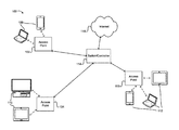
- FIG. 1 illustrates an example of a network environment 100 , in accordance with embodiments of the present invention.
- a wireless networking system can include one or more wireless access points 102 , 104 , 106 which connect various client devices 108 , 110 , 112 .
- client devices may include personal computers, cell phones, handheld messaging devices, laptop computers, set-top boxes, personal data assistants, and any other suitable devices configured to send and receive information over a network.
- wireless local area network implemented using devices that support the IEEE 802.11 family of specifications
- the wireless networking system can support any appropriate wireless network, including an intranet, the Internet, a cellular network, a local area network, or any other such network or combination thereof.
- Components used for such a system can depend at least in part upon the type of network and/or environment selected. Protocols and components for communicating via such a network are well known and will not be discussed herein in detail.
- a given access point can communicate with multiple client devices within range of the access point in the deployment environment.
- the range of any given access point may vary depending on the placement of the access point within the deployment environment (e.g., indoor/outdoor placement, height, local physical obstructions, etc.), antenna type, power output, and local interference (e.g., from other devices operating in the same frequency range).
- switch/controller 114 connects the access points 102 , 104 , 106 to the internet 116 .
- Switch/controller 114 may connect the access points to various network resources, such as a wired LAN, one or more local or remote servers, data stores, and other resources.
- switch/controller 114 can manage more or fewer access points than are shown in FIG. 1 .
- multiple switches may be used to connect other access points to a LAN or other network resource.
- Each access point 102 , 104 , 106 , and/or switch/controller 114 , or a combination of devices can perform various management functions.
- Such management functions can include interference management, power adjustments, device connection management, channel management, and security management (e.g., authentication, authorization, etc.).
- switch/controller 114 may provide authentication and authorization services for requests received to access the wireless network.
- switch/controller 114 may connect to one or more servers to perform authentication and authorization, which may use information stored in one or more data stores to generate a login page to be displayed on the client device, through which account credentials (e.g., username and password) may be provided.
- account credentials e.g., username and password
- information may be served to the client devices using HyperText Markup Language (“HTML”), Extensible Markup Language (“XML”), or another appropriate structured language.
- data stores may refer to a device or combination of devices configured to store, access, and retrieve data. Such devices may include data servers, databases, data storage devices, data storage media, or any combination thereof.
- data stores may be deployed individually, or as a distributed or clustered system.
- the client devices can be assigned to different channels. As more devices connect, devices will share time on the same channel. Devices connected to the same channel each communicate with the access point in turn, with one device transmitting at a given time and other devices deferring communication. Different client devices implementing different versions of the 802.11 specification may connect to the same wireless network. However, as the specification has evolved, the timing parameters have changed. To be backwards compatible, a wireless network implementing an 802.11 standard uses the timing parameters associated with the slowest connected device for a given channel.
- FIG. 2 illustrates an example 200 of communication with multiple transceivers in an access point, in accordance with an embodiment of the present invention.
- Wireless networking systems such as that described above with respect to FIG. 1 , may include access points deployed at different locations.
- a wireless networking system that provides a wireless network in outdoor and indoor spaces may include access points that are deployed indoors, to protect the access points from weather conditions that may adversely affect the lifespan and functioning of the access points.
- access points may be deployed to locations where physical access to the access points is limited, to avoid potential damage to the access points.
- the types of access points may vary depending on the type of network being deployed. For example, some access points may include multiple transceivers to provide access to networks in different frequency bands, increase range, communication speed, etc., which may be selected for the wireless networking system depending on the deployment environment, quality of service requirements, or other network requirements.
- various client devices 202 , 204 can connect to a wireless network through access point 206 .
- each access point may service various client devices within the deployment area.
- access point 206 may include multiple transceivers 208 , 210 each connected to an associated antenna 212 , 214 .
- Each transceiver may be implemented as a separate integrated circuit or module, or multiple transceivers may be implemented in the same module.
- multiple transceivers may be used to support client devices implementing older and slower communication standards (e.g., 802.11b versus 802.11g, 802.11ac, etc.) which operate in different frequency bands.
- transceivers may be utilized to transmit on different channels to improve network performance. Slower devices may be connected to one channel through one transceiver and faster devices may be connected to a different channel through a different transceiver, such that the slower devices do not reduce the performance of the faster devices.
- This use of multiple transceivers can reduce error rates and generally improve network performance and may be used with various connection and channel policies may be used to manage device connections to improve the performance of the wireless network. For example, devices with lower signal strength may be assigned to one channel associated with one transceiver, while devices with higher signal strength may be assigned to a different channel associated with a different transceiver.
- the signals from one transceiver may interfere with the other transceiver.
- a signal transmitted by transceiver 208 may be received by transceiver 210 .
- the transceivers may be located close enough to each other to be electromagnetically coupled, leading to crosstalk between the transceivers and/or connected transmission lines within access point 206 . Similar interference may also be caused when signals are received by one transceiver.
- the potential interference between transceivers in a given access point is in addition to any local interference that may be caused by other nearby devices operating in the same frequency range, physical barriers, and the like. This may reduce the signal to noise ratio (SNR) resulting in reduced range and increased error rates.
- SNR signal to noise ratio
- interference between transceivers can be modeled for each pair or other grouping of transceivers.
- one or more test signals can be used to calibrate the transceivers.
- the one or more test signals can be transmitted by a first transceiver while one or more of the other transceivers are monitored.
- the interference signal detected on the monitored transceiver can be analyzed to determine interference signal characteristics.
- the interference signal characteristics can be compared to the test signal to determine an interference model which represents how signals transmitted by the first transceiver interfere with the other transceivers.
- an interference model can be a one-to-one model between a pair of transceivers or can be a one-to-many model for how one transceiver affects each other transceiver in the access point.
- an interference power threshold can be used to determine whether to model interference on a given transceiver. For example, if the power level of interference on a monitored transceiver is below a threshold during calibration, the interference may not be modeled for that transceiver.
- multiple test signals may be used and the resulting interference from each test signal may be averaged to generate the interference model.
- the interference model can be used to transform signals transmitted by the corresponding transceiver and filter the resulting interference in the other transceivers.
- the transform may reduce the amplitude and add a time delay or phase shift and then the transformed signal can be used to filter the interference.
- FIG. 3 illustrates a block diagram of an access point in a network environment 300 , in accordance with an embodiment of the present invention.
- one or more clients 302 can access a wireless network through an access point 304 .
- access point 304 can include a plurality of transceivers, including transceiver 1 306 to transceiver N 308 .
- each transceiver may be configured to support different operating bands, channels, or other wireless network features.
- Access point 304 can also include interference manager 306 .
- interference manager 310 can determine an interference model 312 for the access point.
- interference manager 310 can transmit one or more test signals from signal cache 314 through each transceiver 306 , 308 in turn, while monitoring the received interference through the remaining transceivers.
- interference may vary from device to device and from deployment environment to deployment environment, such calibration enables the interference for a given deployment to be measured, rather than an average estimate for expected deployments.
- the electromagnetic shielding between transceivers in a given device may vary, leading to different magnitudes of crosstalk between the transceivers.
- the measured interference may be greater than expected prior to deployment.
- each test signal may be a reference signal designed to model typical communication over the wireless network being deployed.
- the signal may be modulated in the same manner as other signals from the wireless network using the same frequency carrier waves.
- the test signals used by interference manager 310 may be requested by a connected client device 302 .
- access point 304 may provide wireless network access to client device 302 through one transceiver.
- Client device 302 may then execute a communication test suite that includes various typical wireless network communications. As the tests are run by client device 302 , access point 304 can measure interference at each transceiver, both as data is transmitted and received. This provides interference measurements under live conditions.
- the tests can then be run for each transceiver in turn to extend the interference model 312 for each component of the access point 304 .
- such testing can be automated by a switch/controller, such as switch controller 114 , or other centralized controller configured to manage multiple access points.
- interference manager 310 can define one or more interference thresholds used during interference modeling.
- the thresholds may be dynamically determined based on e.g., ambient noise levels, or other network and/or environmental conditions.
- interference manager 310 can determine ambient interference levels using a spectrum analyzer.
- interference sources may include other access points, cordless phones, microwaves, and other devices operating on the ISM frequency bands shared by the wireless network. The interference thresholds may then be applied from the ambient noise level.
- the interference measured at transceiver N 308 is not a threshold number of dB greater than the ambient noise level when a test signal is transmitted using transceiver 1 306 , then an interference model may not be determined for transceiver N 308 . If, however, the interference measured at transceiver N ⁇ 1 is greater than the threshold, then the interference model for transceiver N ⁇ 1 associated with transceiver 1 may be determined.
- an interference model can be created with transform values for the change in signal characteristics between the test signal characteristics and the interference signal characteristics (e.g., change in amplitude, change in frequency, change in time delay, etc.).
- the change in signal characteristics may be averaged across multiple test signals, and transform values corresponding to the average change in signal characteristics may be stored in interference model 312 .
- the interference model can be used to reduce interference across transceivers. For example, when a signal is transmitted by transceiver 1 306 , the signal may be temporarily cached in signal cache 314 . Using interference model 312 , one or more transformed signals may be generated.
- the interference model for transceiver 1 306 may include a transform associated with transceiver N 308 and transceiver N ⁇ 1.
- Interference model may then be used to create two transformed signals: one corresponding to transceiver N 308 , transformed using threshold values based on the measured interference caused between transceiver 1 and transceiver N; and a second corresponding to transceiver N ⁇ 1, transformed using threshold values based on the measured interference caused between transceiver 1 and transceiver N ⁇ 1.
- Each transformed signal can be used to filter the signals that are received through transceiver N and transceiver N ⁇ 1.
- the transformed signals can be subtracted from the contemporaneously received signals through the respective transceivers.
- such transformation and subtraction can be performed substantially continuously in real-time as data is transmitted through one or more transceivers and interfering with one or more other transceivers.
- transceiver 1 306 and transceiver N 308 may be operating in different frequency bands, such that harmonics of signals transmitted by transceiver 1 are measured as interference on transceiver N.
- These harmonic interference signals may be measured and modeled as described above where the harmonics interfere in the same frequency range as the main band of the transceiver. Where such interference is measured in predictable frequency ranges outside of the main band, a filter may be applied to that transceiver over the frequency range corresponding to the harmonics.
- FIG. 4 illustrates a method 400 of managing communication with multiple transceivers in a network environment, in accordance with an embodiment of the present invention.
- interference can be monitored between a plurality of transceivers in an access point. As discussed above, such monitoring can be performed when the access point is deployed, enabling the interference of one transceiver to another in the deployment environment to be monitored. In some embodiments, such monitoring can include transmitting a test signal using the first transceiver and receiving an interference signal using the second transceiver. In some embodiments, a test client can be used to send and receive test signals with the access point, enabling the access point to be tested under conditions similar to the live deployment prior to the live deployment of the wireless network.
- the monitored interference may be compared to an interference threshold.
- the interference threshold may be applied relative to an ambient noise level (e.g., caused by other devices within the ISM band, other access points, etc.). If the monitored interference between two or more transceivers is greater than a threshold (e.g., a threshold dB over the ambient noise level), then the interference between those transceivers can be modeled. If it is lower than the threshold, that combination of transceivers may be ignored, or a flag or other data indicating that no transformation should be performed can be stored.
- a threshold e.g., a threshold dB over the ambient noise level
- an interference model can be generated for at least one pair of transceivers from the plurality of transceivers.
- generating the interference model can include analyzing the test signal to determine one or more test signal characteristics and analyzing the interference signal to determine one or more interference signal characteristics.
- the test signal characteristics and the interference signal characteristics include corresponding values of one or more of amplitude, frequency, or time delay.
- the one or more test signal characteristics can be compared to the one or more interference signal characteristics to determine the interference model.
- the interference model can include values that indicate a change in amplitude, a change in frequency, or a change in time delay between the test signal and the interference signal.
- the interference model can include a plurality of transforms associated with a given transceiver, where each of the plurality of transforms are associated with the interference caused by that receiver in a different transceiver from the plurality of transceivers in the access point.
- the access point can be deployed and the wireless network can receive live traffic data from connected devices.
- a signal can be transmitted using a first transceiver.
- An interference manager can monitor the signal that is transmitted and identify one or more transforms in the interference model associated with the first transceiver (e.g., corresponding to interference caused by the first transceiver in other transceivers in the access point).
- the signal can be transformed using the interference model for the at least one pair of transceivers, the at least one pair of transceivers including the first transceiver.
- multiple transformed signals can be generated, each corresponding to a different transceiver that receives interference from the first transceiver.
- the transforms may change the amplitude, frequency, time delay, or other signal characteristics based on the observed changes to the test signals used to generate the interference model.
- signals received through a second transceiver can be filtered using the transformed signal.
- the transformed signal can be subtracted from the signals received through the second transceiver.
- the transformed signal can be shifted 180 degrees out of phase and combined with the signals received through the second transceiver to nullify the interference signal.
- multiple transformed signals can be used to filter the signals received through multiple transceivers, based on the interference model.
- FIG. 5 illustrates a high level block diagram of a computer system 500 , in accordance with an embodiment of the present invention.
- a computer system can include hardware elements connected via a bus 502 , including a network interface 504 , that enables the computer system to connect to other computer systems over a wireless local area network (WLAN), wide area network (WAN), mobile network (e.g., EDGE, 3G, 4G, or other mobile network), or other network.
- Network interface 504 can further include a wired or wireless interface for connecting to infrared, Bluetooth, or other wireless devices, such as other client devices, network resources, or other wireless capable devices.
- the computer system can further include one or more processors 506 , such as a central processing unit (CPU), field programmable gate array (FPGA), application-specific integrated circuit (ASIC), network processor, or other processor.
- processors 506 such as a central processing unit (CPU), field programmable gate array (FPGA), application-specific integrated circuit (ASIC), network processor, or other processor.
- processors may include single or multi-core processors.
- the computer system can include a graphical user interface (GUI) 508 .
- GUI 508 can connect to a display (LED, LCD, tablet, touch screen, or other display) to output user viewable data.
- GUI 508 can be configured to receive instructions (e.g., through a touch screen or other interactive interface).
- I/O interface 510 can include various interfaces for user input devices including keyboards, mice, or other user input devices.
- the computer system may include local or remote data stores 512 .
- Data stores 512 can include various computer readable storage media, storage systems, and storage services, as are known in the art (e.g., disk drives, CD-ROM, digital versatile disk (DVD) or other optical storage, magnetic cassettes, magnetic tape, magnetic disk storage or other magnetic storage devices, relational databases, object storage systems, local or cloud-based storage services, or any other storage medium, system, or service).
- Data stores 510 can include data generated, stored, or otherwise utilized as described herein.
- data stores 512 can include all or portions of interference model 514 as well as interference thresholds and other data.
- Data stores 512 may also include signal cache 516 and other client device data, generated and stored as described above.
- Memory 518 can include various memory technologies, including RAM, ROM, EEPROM, flash memory or other memory technology. Memory 518 can include executable code to implement methods as described herein, such as interference manager 520 .
- a computing device typically will include an operating system that provides executable program instructions for the general administration and operation of that computing device and typically will include a computer-readable storage medium (e.g., a hard disk, random access memory, read only memory, etc.) storing instructions that, when executed by a processor of the server, allow the server to perform its intended functions.
- a computer-readable storage medium e.g., a hard disk, random access memory, read only memory, etc.
- Suitable implementations for the operating system and general functionality of the servers are known or commercially available and are readily implemented by persons having ordinary skill in the art, particularly in light of the disclosure herein.
- the environment in one embodiment is a distributed computing environment utilizing several computer systems and components that are interconnected via communication links, using one or more computer networks or direct connections.
- the environment in one embodiment is a distributed computing environment utilizing several computer systems and components that are interconnected via communication links, using one or more computer networks or direct connections.
- FIG. 5 it will be appreciated by those of ordinary skill in the art that such a system could operate equally well in a system having fewer or a greater number of components than are illustrated in FIG. 5 .
- the depiction of the system 500 in FIG. 5 should be taken as being illustrative in nature and not limiting to the scope of the disclosure.
- the various embodiments further can be implemented in a wide variety of operating environments, which in some cases can include one or more user computers, computing devices or processing devices which can be used to operate any of a number of applications.
- User or client devices can include any of a number of general purpose personal computers, such as desktop or laptop computers running a standard operating system, as well as cellular, wireless, and handheld devices running mobile software and capable of supporting a number of networking and messaging protocols.
- Such a system also can include a number of workstations running any of a variety of commercially-available operating systems and other known applications for purposes such as development and database management.
- These devices also can include other electronic devices, such as dummy terminals, thin-clients, gaming systems, and other devices capable of communicating via a network.
- Most embodiments utilize at least one network that would be familiar to those skilled in the art for supporting communications using any of a variety of commercially-available protocols, such as Transmission Control Protocol/Internet Protocol (“TCP/IP”), Open System Interconnection (“OSI”), File Transfer Protocol (“FTP”), Universal Plug and Play (“UpnP”), Network File System (“NFS”), Common Internet File System (“CIFS”), and AppleTalk.
- the network can be, for example, a local area network, a wide-area network, a virtual private network, the Internet, an intranet, an extranet, a public switched telephone network, an infrared network, a wireless network, and any combination thereof.
- the environment can include a variety of data stores and other memory and storage media as discussed above. These can reside in a variety of locations, such as on a storage medium local to (and/or resident in) one or more of the computers or remote from any or all of the computers across the network. In a particular set of embodiments, the information may reside in a storage-area network (“SAN”) familiar to those skilled in the art. Similarly, any necessary files for performing the functions attributed to the computers, servers, or other network devices may be stored locally and/or remotely, as appropriate.
- SAN storage-area network
- each such device can include hardware elements that may be electrically coupled via a bus, the elements including, for example, at least one central processing unit (“CPU”), at least one input device (e.g., a mouse, keyboard, controller, touch screen, or keypad), and at least one output device (e.g., a display device, printer, or speaker).
- CPU central processing unit
- input device e.g., a mouse, keyboard, controller, touch screen, or keypad
- output device e.g., a display device, printer, or speaker
- Such a system may also include one or more storage devices, such as disk drives, optical storage devices, and solid-state storage devices such as random access memory (“RAM”) or read-only memory (“ROM”), as well as removable media devices, memory cards, flash cards, etc.
- RAM random access memory
- ROM read-only memory
- Such devices can include a computer-readable storage media reader, a communications device (e.g., a modem, a network card (wireless or wired)), an infrared communication device, etc.), and working memory as described above.
- the computer-readable storage media reader can be connected with, or configured to receive, a computer-readable storage medium, representing remote, local, fixed, and/or removable storage devices as well as storage media for temporarily and/or more permanently containing, storing, transmitting, and retrieving computer-readable information.
- the system and various devices also typically will include a number of software applications, modules, services, or other elements located within at least one working memory device, including an operating system and application programs, such as a client application or Web browser.
- Storage media computer readable media for containing code, or portions of code can include any appropriate media known or used in the art, including storage media and communication media, such as but not limited to volatile and non-volatile, removable and non-removable media implemented in any method or technology for storage and/or transmission of information such as computer readable instructions, data structures, program modules, or other data, including RAM, ROM, Electrically Erasable Programmable Read-Only Memory (“EEPROM”), flash memory or other memory technology, Compact Disc Read-Only Memory (“CD-ROM”), digital versatile disk (DVD), or other optical storage, magnetic cassettes, magnetic tape, magnetic disk storage, or other magnetic storage devices, or any other medium which can be used to store the desired information and which can be accessed by a system device.
- RAM random access memory
- ROM read-only memory
- EEPROM Electrically Erasable Programmable Read-Only Memory
- CD-ROM Compact Disc Read-Only Memory
- DVD digital versatile disk
- magnetic cassettes magnetic tape
- magnetic disk storage or other magnetic storage devices
- Disjunctive language such as the phrase “at least one of X, Y, or Z,” unless specifically stated otherwise, is intended to be understood within the context as used in general to present that an item, term, etc., may be either X, Y, or Z, or any combination thereof (e.g., X, Y, and/or Z). Thus, such disjunctive language is not generally intended to, and should not, imply that certain embodiments require at least one of X, at least one of Y, or at least one of Z to each be present.
Landscapes
- Engineering & Computer Science (AREA)
- Computer Networks & Wireless Communication (AREA)
- Signal Processing (AREA)
- Mobile Radio Communication Systems (AREA)
Abstract
Description
Claims (15)
Priority Applications (1)
| Application Number | Priority Date | Filing Date | Title |
|---|---|---|---|
| US15/215,467 US9960874B2 (en) | 2016-07-20 | 2016-07-20 | Techniques for managing interference in a network environment |
Applications Claiming Priority (1)
| Application Number | Priority Date | Filing Date | Title |
|---|---|---|---|
| US15/215,467 US9960874B2 (en) | 2016-07-20 | 2016-07-20 | Techniques for managing interference in a network environment |
Publications (2)
| Publication Number | Publication Date |
|---|---|
| US20180026738A1 US20180026738A1 (en) | 2018-01-25 |
| US9960874B2 true US9960874B2 (en) | 2018-05-01 |
Family
ID=60988159
Family Applications (1)
| Application Number | Title | Priority Date | Filing Date |
|---|---|---|---|
| US15/215,467 Active US9960874B2 (en) | 2016-07-20 | 2016-07-20 | Techniques for managing interference in a network environment |
Country Status (1)
| Country | Link |
|---|---|
| US (1) | US9960874B2 (en) |
Families Citing this family (3)
| Publication number | Priority date | Publication date | Assignee | Title |
|---|---|---|---|---|
| US10548152B2 (en) | 2018-01-23 | 2020-01-28 | Comcast Cable Communications, Llc | Coordinating wireless data communications |
| CN112532330A (en) * | 2019-09-18 | 2021-03-19 | 中兴通讯股份有限公司 | Interference simulation system, method and device, interference test system, method and device |
| CN114930727A (en) * | 2019-11-12 | 2022-08-19 | 蓝色多瑙河系统有限公司 | Cancellation of transmitter signals in phased array transceivers |
Citations (17)
| Publication number | Priority date | Publication date | Assignee | Title |
|---|---|---|---|---|
| US5797084A (en) * | 1995-06-15 | 1998-08-18 | Murata Manufacturing Co. Ltd | Radio communication equipment |
| US6535748B1 (en) * | 1998-05-27 | 2003-03-18 | Nokia Mobile Phones Ltd. | Wireless communication transceiver having a dual mode of operation |
| US20050047384A1 (en) * | 2003-08-27 | 2005-03-03 | Wavion Ltd. | WLAN capacity enhancement using SDM |
| US20080233978A1 (en) * | 2007-03-23 | 2008-09-25 | Sigmatel, Inc. | Wireless handset and wireless headset with wireless transceiver |
| US20080270622A1 (en) * | 2007-03-30 | 2008-10-30 | Stmicroelectronics Pvt. Ltd. | Method and system for optimizing power consumption and reducing mips requirements for wireless communication |
| US20090016263A1 (en) * | 2005-01-26 | 2009-01-15 | Matsushita Electric Industrial Co., Ltd. | Wireless base station and terminal equipment |
| US7486955B2 (en) * | 2004-01-30 | 2009-02-03 | Kabushiki Kaisha Toshiba | Electronic device with antenna for wireless communication |
| US20090111530A1 (en) * | 2007-10-29 | 2009-04-30 | Denso Corporation | Vehicular handsfree apparatus |
| US7881463B1 (en) * | 2003-09-26 | 2011-02-01 | Netopia, Inc. | Wireless digital subscriber line device having reduced RF interference |
| US20130012134A1 (en) * | 2011-07-07 | 2013-01-10 | Cisco Technology, Inc. | Dynamic Clear Channel Assessment Using Spectrum Intelligent Interference Nulling |
| US20150319556A1 (en) * | 2014-04-30 | 2015-11-05 | Issc Technologies Corp | Audio player with bluetooth function and audio playing method thereof |
| US20160277791A1 (en) * | 2014-07-21 | 2016-09-22 | Boe Technology Group Co., Ltd. | Display system, and method of playing bluetooth audio and apparatus of display system |
| US20160372828A1 (en) * | 2015-06-17 | 2016-12-22 | Google Inc. | Phased Array Antenna Self-Calibration |
| US20170094435A1 (en) * | 2015-09-02 | 2017-03-30 | Guangdong Oppo Mobile Telecommunications Corp., Ltd. | Audio playing method, apparatus, and system for multiple playing devices |
| US20170102914A1 (en) * | 2015-10-13 | 2017-04-13 | Samsung Electronics Co., Ltd. | Electronic device and audio ouputting method thereof |
| US20170149856A1 (en) * | 2015-11-20 | 2017-05-25 | Le Holdings(Beijing)Co., Ltd. | Wireless video transmission device, video playing device and method, and system |
| US20170180899A1 (en) * | 2006-12-15 | 2017-06-22 | Proctor Consulting LLP | Smart hub |
-
2016
- 2016-07-20 US US15/215,467 patent/US9960874B2/en active Active
Patent Citations (17)
| Publication number | Priority date | Publication date | Assignee | Title |
|---|---|---|---|---|
| US5797084A (en) * | 1995-06-15 | 1998-08-18 | Murata Manufacturing Co. Ltd | Radio communication equipment |
| US6535748B1 (en) * | 1998-05-27 | 2003-03-18 | Nokia Mobile Phones Ltd. | Wireless communication transceiver having a dual mode of operation |
| US20050047384A1 (en) * | 2003-08-27 | 2005-03-03 | Wavion Ltd. | WLAN capacity enhancement using SDM |
| US7881463B1 (en) * | 2003-09-26 | 2011-02-01 | Netopia, Inc. | Wireless digital subscriber line device having reduced RF interference |
| US7486955B2 (en) * | 2004-01-30 | 2009-02-03 | Kabushiki Kaisha Toshiba | Electronic device with antenna for wireless communication |
| US20090016263A1 (en) * | 2005-01-26 | 2009-01-15 | Matsushita Electric Industrial Co., Ltd. | Wireless base station and terminal equipment |
| US20170180899A1 (en) * | 2006-12-15 | 2017-06-22 | Proctor Consulting LLP | Smart hub |
| US20080233978A1 (en) * | 2007-03-23 | 2008-09-25 | Sigmatel, Inc. | Wireless handset and wireless headset with wireless transceiver |
| US20080270622A1 (en) * | 2007-03-30 | 2008-10-30 | Stmicroelectronics Pvt. Ltd. | Method and system for optimizing power consumption and reducing mips requirements for wireless communication |
| US20090111530A1 (en) * | 2007-10-29 | 2009-04-30 | Denso Corporation | Vehicular handsfree apparatus |
| US20130012134A1 (en) * | 2011-07-07 | 2013-01-10 | Cisco Technology, Inc. | Dynamic Clear Channel Assessment Using Spectrum Intelligent Interference Nulling |
| US20150319556A1 (en) * | 2014-04-30 | 2015-11-05 | Issc Technologies Corp | Audio player with bluetooth function and audio playing method thereof |
| US20160277791A1 (en) * | 2014-07-21 | 2016-09-22 | Boe Technology Group Co., Ltd. | Display system, and method of playing bluetooth audio and apparatus of display system |
| US20160372828A1 (en) * | 2015-06-17 | 2016-12-22 | Google Inc. | Phased Array Antenna Self-Calibration |
| US20170094435A1 (en) * | 2015-09-02 | 2017-03-30 | Guangdong Oppo Mobile Telecommunications Corp., Ltd. | Audio playing method, apparatus, and system for multiple playing devices |
| US20170102914A1 (en) * | 2015-10-13 | 2017-04-13 | Samsung Electronics Co., Ltd. | Electronic device and audio ouputting method thereof |
| US20170149856A1 (en) * | 2015-11-20 | 2017-05-25 | Le Holdings(Beijing)Co., Ltd. | Wireless video transmission device, video playing device and method, and system |
Also Published As
| Publication number | Publication date |
|---|---|
| US20180026738A1 (en) | 2018-01-25 |
Similar Documents
| Publication | Publication Date | Title |
|---|---|---|
| US10039022B2 (en) | Remote diagnosis and cancellation of passive intermodulation | |
| Nika et al. | Towards commoditized real-time spectrum monitoring | |
| KR102381660B1 (en) | Classification of motion detected using radio signals | |
| US10104101B1 (en) | Method and apparatus for intelligent aggregation of threat behavior for the detection of malware | |
| US10212187B2 (en) | Detection of spoof attacks on internet of things (IOT) location broadcasting beacons | |
| US8843155B2 (en) | Multi-band radio frequency detection and location system | |
| US10547618B2 (en) | Method and apparatus for setting access privilege, server and storage medium | |
| US20160241589A1 (en) | Method and apparatus for identifying malicious website | |
| JP2009525680A (en) | Method and system for determining network location of user equipment based on transmitter fingerprint | |
| US9960874B2 (en) | Techniques for managing interference in a network environment | |
| US11283505B2 (en) | Adaptive spatial diagnostics in a wireless network | |
| US20150257156A1 (en) | Dynamic radio frequency mapping | |
| Cotton et al. | An overview of the NTIA/NIST spectrum monitoring pilot program | |
| US20180027506A1 (en) | Techniques for power zoning in a network environment | |
| US20180027468A1 (en) | Techniques for load balancing in a network environment | |
| Namdar et al. | Dispersed chirp‐z transform‐based spectrum sensing and utilisation in cognitive radio networks | |
| US20210194869A1 (en) | Data processing methods, servers, client devices and media for security authentication | |
| CN104348655A (en) | Method and device for determining degree of safety and health of system | |
| Lv et al. | A novel signal separation algorithm based on compressed sensing for wideband spectrum sensing in cognitive radio networks | |
| EP2854437B1 (en) | Detecting the presence of rogue femtocells in enterprise networks | |
| WO2022127854A1 (en) | Method and apparatus for determining transmission frequency, and communication device | |
| Sharma et al. | Robust ML model for human counting using ambient WiFi traffic from multiple sources | |
| Remley et al. | Measurements in harsh RF propagation environments to support performance evaluation of wireless sensor networks | |
| US20180124018A1 (en) | Coordinated application firewall | |
| Adebola et al. | Partial area under the receiver operating characteristics curves of diversity‐enabled energy detectors in generalised fading channels |
Legal Events
| Date | Code | Title | Description |
|---|---|---|---|
| AS | Assignment |
Owner name: ZINWAVE, LTD, UNITED KINGDOM Free format text: ASSIGNMENT OF ASSIGNORS INTEREST;ASSIGNOR:PASULKA, MATTHEW P;REEL/FRAME:042988/0101 Effective date: 20160920 |
|
| STCF | Information on status: patent grant |
Free format text: PATENTED CASE |
|
| AS | Assignment |
Owner name: ZINWAVE LIMITED, UNITED KINGDOM Free format text: ASSIGNMENT OF ASSIGNORS INTEREST;ASSIGNOR:BELL, ANDREW ROBERT;REEL/FRAME:045645/0789 Effective date: 20180425 |
|
| AS | Assignment |
Owner name: MCWANE, INC., ALABAMA Free format text: ASSIGNMENT OF ASSIGNORS INTEREST;ASSIGNOR:ZINWAVE, LTD.;REEL/FRAME:045861/0705 Effective date: 20180509 |
|
| MAFP | Maintenance fee payment |
Free format text: PAYMENT OF MAINTENANCE FEE, 4TH YEAR, LARGE ENTITY (ORIGINAL EVENT CODE: M1551); ENTITY STATUS OF PATENT OWNER: LARGE ENTITY Year of fee payment: 4 |
|
| AS | Assignment |
Owner name: WILSON ELECTRONICS, LLC, UTAH Free format text: ASSIGNMENT OF ASSIGNORS INTEREST;ASSIGNOR:ZINWAVE LIMITED;REEL/FRAME:062943/0273 Effective date: 20230224 |