US9943975B2 - Saw system for miter joints - Google Patents
Saw system for miter joints Download PDFInfo
- Publication number
- US9943975B2 US9943975B2 US13/755,970 US201313755970A US9943975B2 US 9943975 B2 US9943975 B2 US 9943975B2 US 201313755970 A US201313755970 A US 201313755970A US 9943975 B2 US9943975 B2 US 9943975B2
- Authority
- US
- United States
- Prior art keywords
- piece
- stock
- cut
- saw device
- saw
- Prior art date
- Legal status (The legal status is an assumption and is not a legal conclusion. Google has not performed a legal analysis and makes no representation as to the accuracy of the status listed.)
- Active, expires
Links
Images


Classifications
-
- B—PERFORMING OPERATIONS; TRANSPORTING
- B26—HAND CUTTING TOOLS; CUTTING; SEVERING
- B26D—CUTTING; DETAILS COMMON TO MACHINES FOR PERFORATING, PUNCHING, CUTTING-OUT, STAMPING-OUT OR SEVERING
- B26D3/00—Cutting work characterised by the nature of the cut made; Apparatus therefor
- B26D3/02—Bevelling
-
- B—PERFORMING OPERATIONS; TRANSPORTING
- B23—MACHINE TOOLS; METAL-WORKING NOT OTHERWISE PROVIDED FOR
- B23D—PLANING; SLOTTING; SHEARING; BROACHING; SAWING; FILING; SCRAPING; LIKE OPERATIONS FOR WORKING METAL BY REMOVING MATERIAL, NOT OTHERWISE PROVIDED FOR
- B23D59/00—Accessories specially designed for sawing machines or sawing devices
- B23D59/008—Accessories specially designed for sawing machines or sawing devices comprising computers
-
- B—PERFORMING OPERATIONS; TRANSPORTING
- B27—WORKING OR PRESERVING WOOD OR SIMILAR MATERIAL; NAILING OR STAPLING MACHINES IN GENERAL
- B27B—SAWS FOR WOOD OR SIMILAR MATERIAL; COMPONENTS OR ACCESSORIES THEREFOR
- B27B27/00—Guide fences or stops for timber in saw mills or sawing machines; Measuring equipment thereon
- B27B27/10—Devices for moving or adjusting the guide fences or stops
-
- Y—GENERAL TAGGING OF NEW TECHNOLOGICAL DEVELOPMENTS; GENERAL TAGGING OF CROSS-SECTIONAL TECHNOLOGIES SPANNING OVER SEVERAL SECTIONS OF THE IPC; TECHNICAL SUBJECTS COVERED BY FORMER USPC CROSS-REFERENCE ART COLLECTIONS [XRACs] AND DIGESTS
- Y10—TECHNICAL SUBJECTS COVERED BY FORMER USPC
- Y10T—TECHNICAL SUBJECTS COVERED BY FORMER US CLASSIFICATION
- Y10T29/00—Metal working
- Y10T29/49—Method of mechanical manufacture
- Y10T29/49826—Assembling or joining
-
- Y—GENERAL TAGGING OF NEW TECHNOLOGICAL DEVELOPMENTS; GENERAL TAGGING OF CROSS-SECTIONAL TECHNOLOGIES SPANNING OVER SEVERAL SECTIONS OF THE IPC; TECHNICAL SUBJECTS COVERED BY FORMER USPC CROSS-REFERENCE ART COLLECTIONS [XRACs] AND DIGESTS
- Y10—TECHNICAL SUBJECTS COVERED BY FORMER USPC
- Y10T—TECHNICAL SUBJECTS COVERED BY FORMER US CLASSIFICATION
- Y10T29/00—Metal working
- Y10T29/51—Plural diverse manufacturing apparatus including means for metal shaping or assembling
- Y10T29/5176—Plural diverse manufacturing apparatus including means for metal shaping or assembling including machining means
-
- Y—GENERAL TAGGING OF NEW TECHNOLOGICAL DEVELOPMENTS; GENERAL TAGGING OF CROSS-SECTIONAL TECHNOLOGIES SPANNING OVER SEVERAL SECTIONS OF THE IPC; TECHNICAL SUBJECTS COVERED BY FORMER USPC CROSS-REFERENCE ART COLLECTIONS [XRACs] AND DIGESTS
- Y10—TECHNICAL SUBJECTS COVERED BY FORMER USPC
- Y10T—TECHNICAL SUBJECTS COVERED BY FORMER US CLASSIFICATION
- Y10T83/00—Cutting
- Y10T83/04—Processes
- Y10T83/05—With reorientation of tool between cuts
Definitions
- Computer-controlled positioning systems are commonly used in manufacturing environments to position workpieces, such as pieces of lumber, pipes, conduits, sheet metal, extrusions, or the like, quickly and accurately relative to a processing tool, such as a saw.
- a stop serves as a movable fence that contacts an end (or other surface) of a workpiece to set the distance from the end to the processing tool.
- the stop can be driven along a linear axis (i.e., a measurement axis) to adjust the distance of the stop from the tool according to a target dimension, such as a desired length, for a product to be formed by processing the workpiece with the tool.
- Stop-based, linear gauge systems can have various levels of complexity. More sophisticated versions automate control of the tool and use the stop as a pusher to drive movement of the workpiece toward the tool. These pusher-based systems can drive the end of a workpiece toward the tool to multiple stopped positions at which workpiece processing is performed, to create multiple products automatically from a single workpiece. For example, pusher-based systems can create a set of products of desired length automatically based on a cut list.
- more basic stop-based gauge systems combine a more passive stop with manual control of the tool. With these basic systems, a user manually places a workpiece against the stop after the position of the stop has been set based on a desired target dimension, and then manually controls the tool to process the workpiece.
- the present disclosure provides a saw system, including methods and apparatus, for cutting pieces of stock to be installed end-to-end to form miter joints.
- the saw system may include a computer that determines an appropriate saw pivot angle for cutting a proximal end of a second piece of stock, based on a corner angle entered for cutting a distal end of a first piece of stock.
- the saw system may compensate for an offset pivot axis of a saw device based on entered lengths of cut first and second pieces generated respectively with the saw device pivoted to the left and to the right.
- FIG. 1 is a somewhat schematic top view of selected aspects of an exemplary saw system supporting a piece of stock and including a computer-controlled stop and a pivotable saw device oriented to make a square cut through the piece of stock, in accordance with aspects of the present disclosure.
- FIG. 2 is a top view of a set of cut pieces of stock generated with the saw system of FIG. 1 , with the saw device pivoted to the left, centered (square), and pivoted to the right, respectively, in accordance with aspects of the present disclosure.
- FIG. 3 is a schematic top view of the saw system of FIG. 1 , with the pivot axis of the saw device marked by a small circle and having no offset from the square cutting plane or the fence plane of the system, in accordance with aspects of the present disclosure.
- FIG. 4 is another schematic top view of the saw system of FIG. 1 , taken generally as in FIG. 3 but with the pivot axis of the saw device offset to a position behind the fence plane of the system, in accordance with aspects of the present disclosure.
- FIG. 5 is yet another schematic top view of the system of FIG. 1 , taken generally as in FIG. 3 but with the pivot axis of the saw device offset to a position in front of the fence plane of the system, in accordance with aspects of the present disclosure.
- FIG. 6 is still another schematic top view of the system of FIG. 1 , taken generally as in FIG. 3 but with the pivot axis of the saw device offset to the right of the square cutting plane of the system, in accordance with aspects of the present disclosure.
- FIG. 7 is still yet another schematic top view of the system of FIG. 1 , taken generally as in FIG. 3 but with the pivot axis of the saw device offset from both the square cutting plane and the fence plane of the system, in accordance with aspects of the present disclosure.
- FIG. 8 is a top view of a set of pieces of stock that have been cut using the saw system of FIG. 1 , with the saw device having the offset pivot axis of FIG. 7 , and with each piece cut while abutted with the stop at the same position, to illustrate how an offset pivot axis can generate cut pieces of different length for different pivot angles of the saw device, in accordance with aspects of the present disclosure.
- FIG. 9 is a flowchart illustrating exemplary steps for a method of cutting pieces of stock with the saw system of FIG. 1 while compensating for an offset pivot axis of the saw device, in accordance with aspects of the present disclosure.
- FIG. 10 is a schematic top view of FIG. 7 after revision to illustrate an approach for calculating an offset (a “Y-offset”) of the pivot axis from the fence plane of the system, in accordance with aspects of the present disclosure.
- FIG. 11 is a schematic top view of FIG. 7 after revision to illustrate an approach for calculating an offset (an “X-offset”) of the pivot axis from the square cutting plane of the system, in accordance with aspects of the present disclosure.
- FIG. 12 is a schematic top view of the system of FIG. 1 , taken generally as in FIG. 7 but with the saw device pivoted to the left and illustrating a trigonometric approach to calculating an appropriate adjustment to the stop position based on the pivot axis offset and the pivot angle of the saw device, in accordance with aspects of the present disclosure.
- FIG. 13 is a schematic top view of the system of FIG. 1 , taken generally as in FIG. 12 and illustrating a different mathematical approach to calculating an appropriate adjustment to the stop position based on the pivot axis offset and the pivot angle of the saw device, in accordance with aspects of the present disclosure.
- FIG. 14 is an upward view taken inside a room toward a ceiling thereof before installation of crown molding at the perimeter of the ceiling, in accordance with aspects of the present disclosure.
- FIG. 15 is an upward view of the room of FIG. 14 , taken as in FIG. 14 after installation of crown molding at the perimeter of the ceiling, in accordance with aspects of the present disclosure.
- FIG. 16 is a flowchart presenting exemplary steps for a method of cutting and installing a series of stock pieces arranged end-to-end around a wall structure to form miter joints, in accordance with aspects of the present disclosure.
- FIG. 17 is a fragmentary upward view of a room toward a ceiling thereof before installation of crown molding at the perimeter of the ceiling, in accordance with aspects of the present disclosure.
- FIG. 18 is a top view of selected aspects of the saw system of FIG. 1 taken during performance of the method of FIG. 16 to install crown molding in the room of FIG. 17 , with the saw system cutting a proximal end of a first piece of crown molding, in accordance with aspects of the present disclosure.
- FIG. 19 is a top view taken as in FIG. 18 , but with the saw system cutting a distal end of the first piece of crown molding, in accordance with aspects of the present disclosure.
- FIG. 20 is a fragmentary upward view of the room of FIG. 17 taken after installation of the first piece of crown molding, in accordance with aspects of the present disclosure.
- FIG. 21 is a top view taken as in FIG. 18 , but with the saw system cutting a proximal end of a second piece of crown molding for the room of FIG. 17 , in accordance with aspects of the present disclosure.
- FIG. 22 is a top view taken as in FIG. 21 , but with the saw system cutting a distal end of the second piece of crown molding, in accordance with aspects of the present disclosure.
- FIG. 23 is a fragmentary upward view of the room of FIG. 20 taken after installation of the second piece of crown molding, in accordance with aspects of the present disclosure.
- FIG. 24 is a top view taken as in FIG. 18 , but with the saw system cutting a proximal end of a third piece of crown molding for the room of FIG. 17 , in accordance with aspects of the present disclosure.
- FIG. 25 is a top view taken as in FIG. 24 , but with the saw system cutting a distal end of the third piece of crown molding, in accordance with aspects of the present disclosure.
- FIG. 26 is a fragmentary upward view of the room of FIG. 23 taken after installation of the third piece of crown molding, in accordance with aspects of the present disclosure.
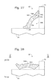
- FIG. 27 is an end view of a piece of crown molding supported by the system of FIG. 1 for a vertical cut through the piece, in accordance with aspects of the present disclosure.
- FIG. 28 is an end view of the piece of crown molding of FIG. 27 supported by the system of FIG. 1 for an inclined cut through the piece of compound molding at a compound angle, in accordance with aspects of the present disclosure.
- FIG. 29 is a top view of the piece of crown molding and saw system of FIG. 28 , as the blade of the saw device is making a tilted cut through the piece, in accordance with aspects of the present disclosure.
- FIG. 30 is a front view of the piece of crown molding and saw system of FIG. 29 , as the blade of the saw device is making the tilted cut through the piece, in accordance with aspects of the present disclosure.
- the present disclosure provides a saw system, including methods and apparatus, for cutting pieces of stock to be installed end-to-end to form miter joints.
- the saw system may include a computer that determines an appropriate saw pivot angle for cutting a proximal end of a second piece of stock, based on a corner angle entered for cutting a distal end of a first piece of stock.
- the saw system may compensate for an offset pivot axis of a saw based on entered lengths of cut first and second pieces generated respectively with the saw pivoted to the left and to the right.
- a saw system may be provided.
- the saw system may include a saw device capable of pivoting to cut pieces of stock at various selectable angles relative to a positioning path.
- the saw system also may include a stop, a driver capable of moving the stop along the positioning path through a range of distances from the saw device, and a computer programmed to control positioning of the stop along the positioning path.
- the following may be entered into the computer for a first piece of stock: (a) a proximal corner angle of the wall structure where a proximal end of the first piece will be fixed, (b) a desired length of the first piece, and (c) a distal corner angle of the wall structure where a distal end of the first piece will be fixed.
- the computer may be allowed to calculate an appropriate position for the stop and pivot angle for the saw device to cut the first piece.
- the first piece may be cut and installed.
- the computer may be allowed to determine an appropriate pivot angle for the saw device to cut a proximal end of a second piece of stock based on the distal corner angle entered for the first piece.
- the proximal end of the second piece may be cut.
- the following may be entered into the computer for the second piece: (a) a desired length of the second piece and (b) a distal corner angle of the wall structure where a distal end of the second piece will be fixed.
- the computer may be allowed to calculate an appropriate position for the stop and pivot angle for the saw device to cut a distal end of the second piece.
- the distal end of the second piece may be cut.
- the second piece may be installed to form a miter joint with the first piece.
- a saw system may be provided.
- the system may include a saw device defining a cutting plane and capable of pivoting about a pivot axis orthogonal to a positioning path to cut stock pieces at various selectable angles relative to the positioning path.
- the system also may include a stop, a driver capable of moving the stop along the positioning path through a range of distances from the saw device, and a computer programmed to control positioning of the stop along the positioning path.
- a first piece of stock may be placed against the stop.
- the first piece may be cut with the saw device pivoted to the left.
- the length of the cut first piece may be measured and entered into the computer.
- a second piece of stock may be placed against the stop.
- the second piece may be cut with the saw device pivoted to the right.
- the length of the cut second piece may be measured and entered into the computer. Additional pieces of stock may be cut to desired lengths with the computer calculating appropriate stop positions based on each desired length, a pivot angle of the saw device for cutting the desired length, and the entered lengths of the cut first and second pieces.
- a saw system for cutting and installation of miter-cut stock pieces may provide substantial advantages over other saw systems. These advantages may include fewer cutting length mistakes, fewer cutting angle errors, a better approach to entering measurements into the system, fewer user calculations, more accurate cut lengths with various saw angles, or any combination thereof, among others.
- This section describes an exemplary saw system 50 for cutting pieces of stock 52 to desired lengths with ends that are square or beveled; see FIGS. 1 and 2 .
- FIG. 1 shows a somewhat schematic top view of selected aspects of saw system 50 supporting stock piece 52 .
- the system may include a pivotable saw device 54 (interchangeably termed a saw), a stop 56 , and a driver 58 operatively connected to stop 56 .
- the driver may be capable of driving movement of the stop, indicated at 60 , in both directions parallel to a positioning axis 62 (interchangeably termed a positioning path) of the system, to different distances from saw device 54 .
- Stop 56 may be engaged with an end of piece 52 (e.g., a square or beveled end), to set the longitudinal position of piece 52 and the distance of the stop and the end of the piece from the saw device (and thus to set the length to which piece 52 will be cut).
- a computer 64 may be in communication with driver 58 , to control the position of the stop along positioning axis 62 .
- the computer can control the length to which the piece is cut, and can apply any adjustments to the stop position necessary to compensate for miter (angled) cuts at one or both ends of the piece, and/or to compensate for an offset of the saw's pivot axis (see Section II).
- the computer may include at least one user input interface 66 (such as a keypad, a keyboard, a mouse, a touchscreen, a data port, or the like) to receive user inputs (e.g., a width of the stock, desired lengths of cut pieces, corner angles of a wall structure, a signal to move the stop, a signal to calibrate the system, or the like).
- the computer also may have at least one output interface 68 (such as a display, a printer, a data port, or the like) to communicate data such as values, status, and settings, to a user.
- the input and output interfaces may be provided by the same device (e.g., a touchscreen).
- the system may include a fence 70 arranged parallel to positioning axis 62 .
- fence 70 may be provided by any one or combination of a housing of driver 58 and a pair of fence members that are disposed along positioning axis 62 on opposite sides of a cutting plane defined by the saw device.
- the fence may provide at least one wall 72 , such as at least one front wall, defining a fence plane 74 that includes, and/or is tangential to, the at least one wall.
- the fence plane may be parallel to positioning axis 62 and may be a vertical plane.
- Fence 70 may be configured to contact a lateral side of piece 52 , to align the piece parallel to positioning axis 62 and to locate a lateral surface region of the piece substantially flush with fence plane 74 .
- the system further may include a base 76 to support piece 52 from underneath.
- the base also may support, position/fix, elevate, and/or connect any combination of other system components, such as saw device 54 , stop 56 , driver 58 , computer 64 , and/or fence 70 .
- Exemplary bases include a stand, table, saw horse, frame, or the like.
- the saw device which in some cases may be described as a miter saw, a miter chop saw, or a compound miter saw, among others, may be any machine or tool that is capable of cutting through piece 52 at various selectable angles with respect to axis 62 .
- the saw device may have a cutting member or blade 78 , which defines a cutting path or cutting plane 80 that can intersect piece 52 orthogonally or obliquely, to produce a square-cut or bevel-cut (mitered) end, respectively.
- the saw device may be a power saw and may be controlled manually and/or by computer 64 , among others.
- the saw device may have a vertical pivot axis, to produce simple miter cuts that are orthogonal to a horizontal plane, and may have a horizontal pivot axis, to produce compound miter cuts that are oblique with respect to horizontal and vertical planes.
- Stock piece 52 may have any suitable properties.
- the piece may be formed of wood, metal, plastic, or a combination thereof, among others.
- the piece may be one of a set of pieces of stock.
- the stock may have any suitable characteristics that are shared within the set, such as the same width, thickness, cross-sectional shape, surface pattern, or any combination thereof, among others.
- FIG. 2 shows a top view of a set of cut pieces 90 - 94 of stock generated by system 50 , with the system generally arranged as in FIG. 1 .
- Each piece may have a square proximal end 96 (or a beveled proximal end 98 or 100 (shown in phantom)) that was engaged with stop 56 , when a distal beveled or square end 102 - 106 was cut by saw device 54 .
- the proximal end may be cut before the distal end.
- the distal end may be to the right or to the left of the proximal end, when being cut, depending upon whether the stop is disposed to the left (as in FIG. 1 ) or to the right of the saw device.
- Pieces 90 - 94 may be generated with saw system 50 from longer stock piece 52 , with the saw device pivoted to the left, centered (square), and pivoted to the right, respectively (i.e., with the three orientations of blade 78 shown in FIG. 1 from right to left, respectively).
- each of pieces 90 - 94 has the same length 110 because the saw's pivot axis is not offset (see Section II).
- the pieces may have the same width 112 , which can be entered into computer 64 to allow the computer to calculate an adjustment to the stop position to compensate, if needed, for any difference between (a) the distance from stop 56 to cutting plane 80 and (b) the desired length.
- beveled proximal end 100 placed against stop 56 would space back side 108 from stop 56 by an added distance that can be calculated using width 112 , the bevel angle of end 100 (and/or the pivot angle of the saw), and trigonometry (see Section III).
- This section describes exemplary configurations of saw system 50 of FIG. 1 , with saw device 54 of the system having an aligned or offset pivot axis, and methods of compensating for the offset pivot axis when the saw device is used in the system at various pivot angles to cut stock; see FIGS. 3-13 .
- FIG. 3 shows a schematic top view of saw system 50 .
- Blade 78 is depicted forward of fence plane 74 (i.e., in a cutting position that would intersect a properly situated piece of stock).
- the blade is shown in three orientations: a center or square position, with cutting plane 80 orthogonal to positioning axis 62 (see FIG. 1 ) and fence plane 74 , a left position (in phantom outline), with the saw device pivoted 45 degrees to the user's left, and a right position (in phantom outline), with the saw device pivoted 45 degrees to the user's right.
- a substantially horizontal x-axis and a substantially horizontal y-axis defined by fence plane 74 and cutting plane 80 , respectively, are shown and used to represent planes 74 and 80 .
- the pivot axis 120 of the saw device marked by a small circle, is vertical and orthogonal to the circle.
- pivot axis 120 does not have an offset because the pivot axis is located at the intersection of the x- and y-axes (i.e., coincident with the line formed by the intersection of fence plane 74 and orthogonal cutting plane 80 ). Since pivot axis 120 is not offset, the saw device can be pivoted in both directions and through a range of angles without changing the length of the piece cut (e.g., see FIG. 2 ), and without the need for the computer to adjust the stop position to compensate for changes in blade position according to pivot angle.
- FIG. 4 shows another top view of saw system 50 , taken generally as in FIG. 3 with pivot axis 120 disposed on the y-axis, but behind the x-axis and fence plane 74 .
- Pieces abutted with the stop and cut with the left, center, and right saw positions, without moving the stop, would be different in length.
- the left cut would produce a shorter piece with a negative left difference 122 relative to the center cut (i.e., the length for a left cut minus the length for a center cut), and the right cut would produce a longer piece with a negative right difference 124 relative to the center cut (i.e., the length for a center cut minus the length for a right cut).
- the left and right differences, as defined here, thus would be equal in magnitude and sign.
- FIG. 5 shows yet another top view of saw system 50 , taken generally as in FIG. 3 with pivot axis 120 disposed on the y-axis, but below the x-axis and fence plane 74 in the drawing (i.e., forward of the fence plane during use).
- pieces cut with the left, center, and right saw positions, without moving the stop would be different in length.
- the left cut would produce a longer piece with a positive left difference 122
- the right cut would produce a shorter piece with a positive right difference 124 .
- the left and right differences thus would be equal in magnitude and sign.
- a Y-offset 126 of pivot axis 120 is equal in magnitude to each of the left and right differences.
- the Y-offset is positive (above the x-axis in the drawing) if the left and right differences are negative, and is negative if the left and right differences are positive.
- FIG. 6 shows still another top view of saw system 50 , taken generally as in FIG. 3 but with pivot axis 120 disposed on the x-axis, but to the right of the y-axis and central cutting plane 80 .
- blade 78 is shown connected to pivot axis 120 by a pivot arm 128 .
- Pieces cut with the left and right saw positions, without moving the stop, would have the same length, which would be different than the center cut length.
- the left and right cuts each would produce a shorter piece with the same magnitude and opposite sign of left and right differences 122 , 124 relative to the center cut.
- An X-offset 130 corresponding to the length of arm 128 can be calculated from left difference 122 and right difference 124 as described below.
- FIG. 7 shows still yet another top view of saw system 50 , taken generally as in FIG. 3 , but with pivot axis 120 offset from both the x- and y-axes (i.e., offset from both fence plane 74 and orthogonal cutting plane 80 .
- pivot axis 120 is offset from the intersection of the x- and y-axes by X-offset 130 and Y-offset 126 .
- left difference 122 has a different magnitude than right difference 124 .
- FIG. 8 shows a top view of pieces 90 - 94 of FIG. 2 , but with the pieces cut using the saw system of FIG. 1 arranged with the offset pivot axis of FIG. 7 . Left and right differences 122 , 124 are indicated.
- FIG. 9 is a flowchart 150 illustrating exemplary steps for a method of cutting pieces of stock with the system of FIG. 1 , to compensate for an offset pivot axis of the saw device according to the pivot angle of the saw.
- the steps presented here may be performed in any suitable combination and order, and each step, if performed, may be performed one or more times.
- the saw system may be calibrated for square cuts with the saw in its centered position.
- Calibration generally includes cutting one or more pieces of stock (e.g., to generate a longer piece and a shorter piece), measuring the lengths of the pieces, and entering the lengths into the computer. The computer can then correlate the lengths with the stop position for each length, and determine how to accurately position the stop for other desired lengths. Further aspects of calibrating the saw system are described in the U.S. Patent Application Publication No. 2011/0056344 A1, published Mar. 10, 2011, which is incorporated herein by reference.
- the stop position may be set for determining left and right differences 122 , 124 , indicated at 152 .
- the computer may be instructed and/or allowed to position the stop for pivot point determination.
- the stop may be moved to a separation distance from the orthogonal cutting plane, such as about 6, 8, 10, or 12 inches, among others. The distance may be relatively short, to minimize the length of stock used. In some cases, a piece of stock may be cut after the stop is positioned and with the saw set to make a square cut, to confirm the accuracy of the center cut length.
- the saw may be pivoted to the left, indicated at 154 .
- the saw may be pivoted by any suitable angle from orthogonal to the positioning axis to set the angle of the saw (and saw blade).
- the saw may be set to an angle of 45 degrees, which simplifies subsequent pivot point calculations, as described further below.
- the computer may be programmed to perform the pivot point calculations based on another predefined angle value for the left and right differences, and/or may be programmed to perform the calculations based on an angle(s) entered by the user.
- a first piece of stock may be cut, indicated at 156 , with the saw pivoted to the left.
- the length of the first piece may be measured, and the length entered into the computer, indicated at 158 .
- the length of the first piece allows the computer to calculate left difference 122 (e.g., see FIGS. 4-8 ).
- the saw may be pivoted to the right, indicated at 160 , to set the angle of the saw to the right.
- the saw may be pivoted by any suitable angle from orthogonal to the positioning axis.
- the saw may be pivoted by the same angle value (e.g., 45 degrees) as for determining left difference 122 , but in the opposite pivotal direction.
- a second piece of stock may be cut, indicated at 162 , with the saw pivoted to the right.
- the length of the second piece may be measured, and the length entered into the computer, indicated at 164 .
- the length of the second piece allows the computer to calculate right difference 124 (e.g., see FIGS. 4-8 ).
- the second piece of stock may be cut before or after the first piece of stock.
- a pivot offset of the saw may be calculated, indicated at 166 .
- X-offset 130 and Y-offset 126 may be calculated from left and right differences 122 , 124 (e.g., see FIGS. 4-7 ), as described in more detail below.
- Additional pieces of stock may be cut, with the computer controlling the stop position to compensate for the pivot offset of the saw, indicated at 168 .
- the computer may apply an adjustment to the stop position based on the lengths of the first and second pieces, the left and right differences, the calculated pivot offset, and/or the pivot angle (angle value and direction) of the saw for each cut, among others.
- FIG. 10 shows a revised version of FIG. 7 to illustrate an approach for determining Y-offset 126 .
- Pivot arm 128 forms a right angle between the left pivot position and the right pivot position, to define a square 180 .
- the length of the square's diagonal is the sum of left difference 122 and right difference 124
- FIG. 11 shows another revised version of FIG. 7 to illustrate an approach for determining X-offset 130 .
- the end of pivot arm 128 defines a circle 190 if the pivot arm travels through a full turn about pivot axis 120 .
- isosceles right triangles 192 , 194 are constructed conceptually with left difference 122 and right difference 124 , respectively, the top point of triangle 192 is 22.5 degrees above horizontal, and the top point of triangle 194 is 22.5 degrees below horizontal, with the vertical line between these two points tangent to circle 190 .
- half of the difference between left difference 122 and right difference 124 is the height of a right triangle 196 with a base of X-offset 130 and an interior angle of 22.5 degrees.
- FIG. 12 is a schematic top view of system 50 , taken generally as in FIG. 7 , but with the saw pivoted to the left by an angle ⁇ (e.g., 40 degrees to the left in the present illustration).
- FIG. 12 helps to explain a trigonometric approach to calculating an appropriate pivot compensation or adjustment 200 (“p”) for the stop position based on the saw's pivot axis offset and the pivot angle of the saw.
- a right triangle 202 in the drawing has a base (“c”), a height (“d”), an interior angle (“ ⁇ ”), and a hypotenuse equal in length to arm 128 (and thus X-offset 130 ).
- d X offset*sin( ⁇ ) (7)
- p (( d+Y offset)*tan( ⁇ ))+ X offset ⁇ c (8)
- FIG. 13 is a schematic top view of the system of FIG. 1 , taken generally as in FIG. 12 and illustrating a different mathematical approach to calculating an appropriate compensation or adjustment 200 (“p”) for the stop position based on the saw's pivot axis offset and the pivot angle of the saw for a given cut to be made.
- This section describes exemplary methods that use saw system 50 to cut pieces of stock (such as molding) for installation in a mated configuration to create miter joints; see FIGS. 14-30 .
- FIG. 14 shows an upward view of an enclosed area of a building, such as a room 250 , taken from inside the room toward a ceiling 252 thereof, before installation of molding with the aid of saw system 50 .
- the enclosed area may be disposed in any suitable building and may have a wall structure 254 formed by one or more connected walls 256 .
- the walls may be vertical or may have any other suitable orientation.
- the wall structure may at least partially or completely encircle ceiling 252 and a floor opposite the ceiling. Molding may be installed adjacent (e.g., against) the wall structure at any suitable position, such as adjacent (e.g., against) ceiling 252 (with crown molding), adjacent the floor (with base molding), and/or intermediate the floor and ceiling.
- the wall structure may be provided by the exterior of a building or the interior or exterior of another structure or article (e.g., an article of furniture, a cabinet, shelves, drawers, a deck, stairs, a door, a window, etc.).
- another structure or article e.g., an article of furniture, a cabinet, shelves, drawers, a deck, stairs, a door, a window, etc.
- the wall structure may create a plurality of corners where adjacent walls 256 meet one another.
- the corners may include inside (concave) corners and outside (convex) corners.
- Each corner forms a corner angle (interchangeably termed a wall angle), which may or may not be approximately a right angle.
- the angle of each corner may be measured with an angle finder, which may measure and provide an angle through air for each corner, as shown here, or an angle less than 180 degrees for both inside and outside corners.
- many of the corners are formed by walls that are not square to one another, to produce angles of inside corners that are not exactly 90 degrees and angles of outside corners that are not exactly 270 degrees. Accordingly, the angle at which molding is cut for each corner should be based on a measured value for the particular angle of the corner, to provide a custom fit. This process can be laborious and error-prone without the benefit of saw system 50 .
- Each wall can be measured horizontally (e.g., near the ceiling or floor), to determine a desired length for each piece of molding.
- each wall has a dimension, labeled serially as A to L and measured between flanking corners parallel to ceiling 252 (or the floor, among others). The dimension corresponds to the desired length for a piece of molding to be attached to each wall.
- a user of system 50 can measure and record all of the wall dimensions (e.g., A to L) and corner angles of a room (or other wall structure) before cutting and installing any of the molding (or other pieces of stock), or may measure a wall dimension and a corner angle after cutting and installing each piece of stock and before cutting and installing the next piece of stock.
- FIG. 15 show an upward view of room 250 taken after installation of pieces 258 A to 258 L of crown molding around wall structure 254 of room 250 adjacent ceiling 252 .
- the pieces may be cut and installed on the walls of wall structure 254 to form miter joints 260 at which opposed ends of adjacent pieces are mated (i.e., arranged end-to-end and fitted together in close proximity and/or abutted).
- the pieces may be cut and/or installed in sequence, starting with a piece of molding for one of the walls (e.g., piece 258 A) and then working around the room in a counterclockwise or clockwise direction (e.g., piece 258 B next, then piece 258 C, and so on, until piece 258 L completes the circuit of molding around the room).
- the molding may be installed around a wall structure without forming a complete circuit.
- FIG. 16 shows a flowchart 280 presenting exemplary steps for a method of cutting and installing a series of stock pieces configured to be mated at miter joints around a wall structure, such as wall structure 254 of FIGS. 14 and 15 .
- the steps of the method may be performed in any suitable order and combination, and may be combined with or modified by any suitable steps, features, or aspects of the present disclosure.
- a width of stock pieces to be used may be entered, indicated at 282 .
- the width, and any of the measured angles or lengths described below, may be entered into computer 64 of system 50 , such as via input interface 66 (see FIG. 1 ).
- a value for a proximal corner angle of the wall structure may be entered, indicated at 284 .
- the proximal corner forming the proximal corner angle may be a site where a proximal end of a first piece of stock will be fixed, as a result of attaching the first piece to the wall structure.
- the proximal corner angle may be measured by any suitable instrument, such as a digital or analog angle finder.
- the value entered may, for example, be less than or greater than 180 degrees, and may or may not be equal to 90 degrees. Whether the proximal corner angle is an inside corner or an outside corner also may be entered into the computer.
- the computer may be programmed and/or allowed to calculate an orientation for the saw to cut a proximal end of the first piece of stock based on the proximal corner angle entered.
- the orientation may include an appropriate pivot angle (i.e., a single angle or a compound angle) for setting the saw, namely, at least one pivot angle value and at least one pivot direction (e.g., left or right, or clockwise or counterclockwise, among others).
- the computer may obtain an appropriate orientation for the saw by dividing the entered proximal corner angle by two and then subtracting the result from 90, and selecting right as a pivot direction.
- the computer may obtain an appropriate orientation for the saw by dividing the entered proximal corner angle by two, subtracting the result from 90, and selecting left as a pivot direction. If the proximal corner is an outside corner and the entered value is greater than 180 degrees, in addition to selecting left as a pivot direction, the computer may obtain an appropriate orientation for the saw by selecting left as a pivot direction and dividing by two and then subtracting 90, subtracting 180 and then dividing by two, or the like.
- the saw may be set to the calculated orientation, indicated at 286 .
- the orientation calculated by the computer may be outputted and/or communicated to the user visually and/or audibly. For example, the orientation may be displayed, printed, spoken, or the like. In any event, the user may turn the saw to the orientation calculated and outputted by the computer.
- a proximal end of the first piece of stock may be cut, indicated at 288 , after setting the saw to the orientation calculated from the proximal corner angle.
- the first piece of stock generally is not in contact with the stop of the saw system. Accordingly, the computer may not need to calculate an appropriate stop position for cutting the proximal end.
- a desired length of the first piece of stock may be entered, indicated at 290 .
- the desired length may be a desired final length after both ends of the piece of stock have been cut by the saw system.
- the desired length may be entered by pressing keys or as data communicated to computer 64 from a measuring device operated by the user. In any event, the length may be measured from the proximal corner to an adjacent distal corner where a distal end of the piece will be fixed, as a result of attaching the piece to the wall structure.
- a value for a distal corner angle also may be entered, indicated at 292 .
- the distal corner for which the value is entered may be a site where the distal end of the first piece of stock will be fixed, as a result of attaching the piece to the wall structure. Whether the distal corner angle is an inside corner or an outside corner also may be entered.
- the computer may be programmed and/or allowed to calculate an orientation for the saw to cut the distal end of the piece of stock based on the distal corner angle value entered.
- the orientation may include an appropriate pivot angle for setting the saw, namely, at least one pivot angle value and direction (e.g., left or right, or clockwise or counterclockwise, among others). For example, if the distal corner is an inside corner and the stock will be cut vertically, the computer may obtain an appropriate orientation for the saw by dividing the entered distal corner angle value by two and subtracting the result from 90, and selecting left as a pivot direction.
- the computer may obtain an appropriate orientation for the saw by dividing the entered distal corner angle value by two and selecting right as a pivot direction. If the distal corner is an outside corner and the entered value is greater than 180 degrees, in addition to selecting right as a pivot direction, the computer may obtain an appropriate orientation for the saw by dividing the angle value by two and then subtracting a value of 90, subtracting a value of 180 and then dividing by two, or the like.
- the saw may be set to the calculated orientation, indicated at 294 .
- the orientation may be outputted and/or communicated as described above.
- the computer may be programmed to control movement of stop 56 to an appropriate position for cutting the desired length.
- the computer may apply one or more adjustments to determine the appropriate position of the stop for cutting the desired length. These adjustments may compensate for a pivot axis offset (if any) of the saw, by calculating and compensating for the consequence of this offset on cutting plane position at the fence plane for the particular saw orientation to be used for cutting the distal end (e.g., see FIGS. 3-13 ). These adjustments also or alternatively may compensate for a gap between the back edge of the piece and the stop, at the beveled proximal end of the piece. Compensation for the gap can be calculated from the width of the stock and the orientation of the saw when the proximal end was cut, as described further below.
- the distal end of the first piece may be cut, indicated at 296 , with the saw set to the calculated orientation, the stop disposed in the appropriate position, and the proximal end of the first piece engaged with the stop.
- the double-cut first piece may be installed, indicated at 298 .
- Installation generally involves attaching the piece to the wall structure.
- the piece may be installed such that the proximal end of the first piece is fixed at the proximal corner and the distal end of the first piece is fixed at the distal corner.
- Steps 286 to 298 next may be repeated for a second piece of stock, indicated at 300 .
- the computer may determine an appropriate orientation for the saw to cut the proximal end of the second piece based on the distal corner angle entered for the first piece of stock. For example, the computer may select and communicate the same pivot angle value calculated for cutting the distal end of the first piece, and an opposite pivot direction from that used for cutting the distal end of the first piece.
- the second piece of stock when cut to the desired length, may be installed end-to-end with the first piece of stock, to form a miter joint, with the distal end of the first piece abutted with the proximal end of the second piece. Any of steps 286 to 298 may be performed for the second piece of stock after the first piece of stock is cut and/or and after the first piece of stock is installed.
- Steps 286 to 298 further may be repeated for additional pieces of stock, indicated at 300 .
- the computer may determine an appropriate pivot angle for cutting the proximal end of each successive piece of stock based on distal corner angle information entered for the immediately-preceding piece, as described above for the second piece of stock.
- Each additional piece of stock may be cut at both ends and then installed with its proximal end adjacent the distal end of the immediately-preceding piece of stock, to create another miter joint.
- FIGS. 17-26 depict exemplary configurations produced before, during, and after performance of an exemplary embodiment of the method of FIG. 16 to install a contiguous series of three crown molding pieces in an oddly-shaped, small alcove of a room 308 .
- FIG. 17 shows a fragmentary upward view of room 308 before installation of crown molding at the perimeter of the ceiling, against walls 310 - 314 , and between corners 316 - 322 .
- FIG. 18 shows a top view of selected aspects of saw system 50 (see FIG. 1 ), with saw blade 78 cutting a proximal end of a first piece 324 of crown molding 326 .
- a user has entered an angle value (“90”) and an inside corner designation (“I”) for proximal corner 316 (see FIG. 17 ).
- the desired length (“Len”) of the piece may or may not have been entered already at this point, and may or may not be displayed. Here, no value is displayed yet for the length.
- the user has turned the saw to the indicated setting and is in the process of cutting the proximal end of first piece 324 . Stop 56 is spaced from the first piece.
- FIG. 19 shows saw system 50 cutting a distal end of first piece 324 .
- the user has turned the saw to the displayed orientation.
- the user also has entered a desired length value (32 inches) for the first piece, which is the distance measured by the user from corner 316 to corner 318 (see FIG. 17 ).
- Computer 64 has calculated an appropriate position for stop 56 based on the entered length value (no miter adjustment to the stop position is needed in this case), and has controlled movement of the stop to that position.
- the cut proximal end of the first piece has been placed against stop 56 , and the user is in the process of cutting the distal end of the first piece.
- FIG. 20 shows room 308 after installation of double-cut first piece 324 of crown molding.
- the proximal end of the piece is fixed in proximal corner 316
- the distal end of the piece is fixed in distal corner 318 (also see FIG. 17 ).
- FIG. 21 shows a top view of selected aspects of saw system 50 with saw blade 78 cutting a proximal end of a second piece 328 of crown molding 326 .
- the second piece may be cut from a virgin length of stock, as shown here, or from a remaining length of stock resulting from one or more previous cuts (e.g., a remaining portion of a stock piece left after cutting off first piece 324 ).
- the computer also has determined an appropriate orientation for the saw to cut the proximal end of the second piece, based on distal corner information entered previously by the user for the first piece.
- the user has turned the saw to the indicated setting and is in the process of cutting the proximal end of second piece 328 , with stop 56 not in contact with the second piece.
- FIG. 22 shows saw system 50 cutting a distal end of second piece 328 .
- the user has turned the saw to the displayed orientation.
- the user also has entered a desired length value (20 inches) for the second piece, which is the distance measured by the user from corner 318 to corner 320 (see FIG. 17 ).
- Computer 64 has calculated an appropriate position for stop 56 based on the entered length value (no miter adjustment to the stop position is needed in this case), and has controlled movement of the stop to that position.
- the proximal end of the second piece has been placed against stop 56 , and the user is in the process of cutting the distal end of the second piece.
- FIG. 23 shows room 308 after installation of double-cut second piece 328 end-to-end with previously installed first piece 324 , to form a miter joint 330 .
- the proximal end of the second piece is fixed in corner 318
- the distal end of the piece is fixed in corner 320 (also see FIG. 17 ).
- FIG. 24 shows a top view of selected aspects of saw system 50 with saw blade 78 cutting a proximal end of a third piece 332 of crown molding 326 .
- the third piece may be cut from a virgin length of stock, as shown here, or from a remaining length of stock resulting from one or more previous cuts (e.g., a remaining portion of a stock piece left after cutting off first piece 324 and/or second piece 328 ).
- the computer also has determined an appropriate orientation for the saw to cut the proximal end of the third piece, based on the distal corner angle information entered previously by the user for the second piece.
- the user has turned the saw to the indicated setting and is in the process of cutting the proximal end of third piece 332 , with stop 56 not in contact with the third piece.
- FIG. 25 shows saw system 50 cutting a distal end of third piece 332 .
- the user has turned the saw to the displayed orientation.
- the user also has entered a desired length value for the third piece (12 inches), which is the distance measured by the user from corner 320 to corner 322 (see FIG. 17 ).
- Computer 64 has calculated an appropriate position for stop 56 based on the entered length value, and has controlled movement of the stop to that position.
- the appropriate stop position includes a miter compensation 334 that positions stop 56 at a greater distance from saw blade 78 than the desired (measured) length 336 .
- desired length 336 is determined here by the back edge of third piece 332 (adjacent the fence), which is spaced from stop 56 by the length of the beveled region of the proximal end of third piece 332 (i.e., by miter compensation 334 ).
- miter offset width*tan(saw angle)
- FIG. 26 shows room 308 after installation of double-cut third piece 332 end-to-end with previously installed second piece 328 , to form another miter joint.
- the proximal end of the third piece is fixed in corner 320
- the distal end of the piece is fixed in corner 322 (also see FIG. 17 ).
- Additional pieces of crown molding can be cut and installed to form additional miter joints.
- additional pieces are cut and installed until the last piece forms a miter joint with the initial piece, and the crown molding forms a complete circuit around the room.
- the crown molding does not form a complete circuit.
- base molding is installed adjacent the floor.
- the pieces of stock are installed on a different type of wall structure and/or the stock is not crown molding.
- FIG. 27 shows an end view of a stock piece 340 of crown molding supported by system 50 for a vertical cut.
- piece 340 is supported upside down relative to its prospective mounted orientation on a wall and ceiling.
- the crown molding may have a wall-engagement surface region 342 , which is abutted with fence 70 (corresponding to the wall), and a ceiling-engagement surface region 344 arranged orthogonally to surface region 342 and abutted with base 76 (corresponding to the ceiling).
- Surface regions 342 and 344 may be separated from one another by an inner surface region 346 that does not contact the wall or ceiling when the crown molding is mounted operatively to cover the seam between the wall and ceiling.
- the crown molding shown here when mounted, forms a hollow space 348 bounded by inner surface region 346 and areas of the wall and ceiling disposed generally between surface regions 342 and 344 . Also, the crown molding is configured to form a spring angle 350 between the wall and a plane 352 defined by the crown molding.
- Crown molding can be cut in the inverted configuration shown in FIG. 27 , with the saw blade vertical, to create pieces suitable for forming miter joints at inside and outside corners of a wall structure.
- the saw can be pivotable about a vertical pivot axis only, to orient the saw blade appropriately for cutting each beveled end at a selectable angle.
- FIG. 28 shows an end view of the piece of crown molding of FIG. 27 supported by system 50 with the piece in a different orientation, namely, with the piece lying flat on base 76 .
- the inverted configuration of FIG. 27 with the crown molding supported at spring angle 350 , may not be suitable in some cases, such as when the crown molding is too wide to be supported reliably at the spring angle by system 50 .
- system 50 can be utilized to cut pieces of crown molding with the pieces lying flat, as shown in FIG. 28 .
- the blade of a compound miter saw is oriented for an inclined cut through the stock piece at a compound angle, by pivoting the saw about a horizontal axis and about a vertical axis.
- FIGS. 29 and 30 show top and side views of piece 340 being cut with the piece lying flat as in FIG. 28 .
- the piece can be cut as described above (e.g., see FIGS. 18 and 19 ) according to the measured corner angle of a wall structure, to provide a cut proximal end or distal end for a miter joint.
- Computer 64 can be programmed to calculate vertical and horizontal angle components for pivoting the saw to achieve the compound angle.
- the horizontal angle component or swivel angle 354 (interchangeably termed a miter angle) describes pivoting the saw about a vertical pivot axis.
- the vertical angle component or tilt angle 356 (interchangeably termed a bevel angle) describes pivoting the saw about a horizontal pivot axis.
- Appropriate swivel and tilt angles for cutting piece 340 can be calculated based on the spring angle of the crown molding and the measured corner angle, as follows:
- Method 280 of FIG. 16 can be utilized with compound angles, too.
- the swivel angle and tilt angle for cutting the proximal end of a second piece of stock can be determined based on the entered distal corner angle where a distal end of a first piece of stock will be (or already is) fixed.
Abstract
Saw system, including methods and apparatus, for cutting pieces of stock to be installed end-to-end to form miter joints. In some embodiments, the saw system may include a computer that determines an appropriate saw pivot angle for cutting a proximal end of a second piece of stock, based on a corner angle entered for cutting a distal end of a first piece of stock. In some embodiments, the saw system may compensate for an offset pivot axis of a saw device based on entered lengths of cut first and second pieces generated respectively with the saw device pivoted to the left and to the right.
Description
This application is based upon and claims the benefit under 35 U.S.C. § 119(e) of U.S. Provisional Patent Application Ser. No. 61/593,754, filed Feb. 1, 2012, which is incorporated herein by reference in its entirety for all purposes.
This application incorporates by reference in its entirety for all purposes U.S. Patent Application Publication No. 2011/0056344 A1, published Mar. 10, 2011.
Computer-controlled positioning systems, also termed gauge systems, are commonly used in manufacturing environments to position workpieces, such as pieces of lumber, pipes, conduits, sheet metal, extrusions, or the like, quickly and accurately relative to a processing tool, such as a saw. In stop-based gauge systems, a stop serves as a movable fence that contacts an end (or other surface) of a workpiece to set the distance from the end to the processing tool. The stop can be driven along a linear axis (i.e., a measurement axis) to adjust the distance of the stop from the tool according to a target dimension, such as a desired length, for a product to be formed by processing the workpiece with the tool.
Stop-based, linear gauge systems can have various levels of complexity. More sophisticated versions automate control of the tool and use the stop as a pusher to drive movement of the workpiece toward the tool. These pusher-based systems can drive the end of a workpiece toward the tool to multiple stopped positions at which workpiece processing is performed, to create multiple products automatically from a single workpiece. For example, pusher-based systems can create a set of products of desired length automatically based on a cut list. On the other hand, more basic stop-based gauge systems combine a more passive stop with manual control of the tool. With these basic systems, a user manually places a workpiece against the stop after the position of the stop has been set based on a desired target dimension, and then manually controls the tool to process the workpiece.
Many craftsmen, such as framers, finish carpenters, cabinet installers, and cabinetmakers, could benefit from the use of a gauge system to cut pieces with beveled ends for creating miter joints. However, to make the gauge system more attractive to these craftsmen, the system could be improved, for example, to be easier to learn, more accurate at various saw angles, and/or and less likely to induce cutting errors by the user.
The present disclosure provides a saw system, including methods and apparatus, for cutting pieces of stock to be installed end-to-end to form miter joints. In some embodiments, the saw system may include a computer that determines an appropriate saw pivot angle for cutting a proximal end of a second piece of stock, based on a corner angle entered for cutting a distal end of a first piece of stock. In some embodiments, the saw system may compensate for an offset pivot axis of a saw device based on entered lengths of cut first and second pieces generated respectively with the saw device pivoted to the left and to the right.
The present disclosure provides a saw system, including methods and apparatus, for cutting pieces of stock to be installed end-to-end to form miter joints. In some embodiments, the saw system may include a computer that determines an appropriate saw pivot angle for cutting a proximal end of a second piece of stock, based on a corner angle entered for cutting a distal end of a first piece of stock. In some embodiments, the saw system may compensate for an offset pivot axis of a saw based on entered lengths of cut first and second pieces generated respectively with the saw pivoted to the left and to the right.
An exemplary method of cutting and installing pieces of stock around a wall structure is provided. In the method, a saw system may be provided. The saw system may include a saw device capable of pivoting to cut pieces of stock at various selectable angles relative to a positioning path. The saw system also may include a stop, a driver capable of moving the stop along the positioning path through a range of distances from the saw device, and a computer programmed to control positioning of the stop along the positioning path. The following may be entered into the computer for a first piece of stock: (a) a proximal corner angle of the wall structure where a proximal end of the first piece will be fixed, (b) a desired length of the first piece, and (c) a distal corner angle of the wall structure where a distal end of the first piece will be fixed. The computer may be allowed to calculate an appropriate position for the stop and pivot angle for the saw device to cut the first piece. The first piece may be cut and installed. The computer may be allowed to determine an appropriate pivot angle for the saw device to cut a proximal end of a second piece of stock based on the distal corner angle entered for the first piece. The proximal end of the second piece may be cut. The following may be entered into the computer for the second piece: (a) a desired length of the second piece and (b) a distal corner angle of the wall structure where a distal end of the second piece will be fixed. The computer may be allowed to calculate an appropriate position for the stop and pivot angle for the saw device to cut a distal end of the second piece. The distal end of the second piece may be cut. The second piece may be installed to form a miter joint with the first piece.
An exemplary method of cutting pieces of stock is provided. In the method, a saw system may be provided. The system may include a saw device defining a cutting plane and capable of pivoting about a pivot axis orthogonal to a positioning path to cut stock pieces at various selectable angles relative to the positioning path. The system also may include a stop, a driver capable of moving the stop along the positioning path through a range of distances from the saw device, and a computer programmed to control positioning of the stop along the positioning path. A first piece of stock may be placed against the stop. The first piece may be cut with the saw device pivoted to the left. The length of the cut first piece may be measured and entered into the computer. A second piece of stock may be placed against the stop. The second piece may be cut with the saw device pivoted to the right. The length of the cut second piece may be measured and entered into the computer. Additional pieces of stock may be cut to desired lengths with the computer calculating appropriate stop positions based on each desired length, a pivot angle of the saw device for cutting the desired length, and the entered lengths of the cut first and second pieces.
A saw system for cutting and installation of miter-cut stock pieces may provide substantial advantages over other saw systems. These advantages may include fewer cutting length mistakes, fewer cutting angle errors, a better approach to entering measurements into the system, fewer user calculations, more accurate cut lengths with various saw angles, or any combination thereof, among others.
Further aspects of the present disclosure are presented in the following sections: (I) exemplary saw system with computer-controlled stop positioning, (II) compensation for an offset pivot axis of a saw device of the system, and (III) exemplary methods of utilizing the saw system to create miter joints.
I. Exemplary Saw System with Computer-Controlled Stop Positioning
This section describes an exemplary saw system 50 for cutting pieces of stock 52 to desired lengths with ends that are square or beveled; see FIGS. 1 and 2 .
A computer 64 may be in communication with driver 58, to control the position of the stop along positioning axis 62. As a result, the computer can control the length to which the piece is cut, and can apply any adjustments to the stop position necessary to compensate for miter (angled) cuts at one or both ends of the piece, and/or to compensate for an offset of the saw's pivot axis (see Section II). The computer may include at least one user input interface 66 (such as a keypad, a keyboard, a mouse, a touchscreen, a data port, or the like) to receive user inputs (e.g., a width of the stock, desired lengths of cut pieces, corner angles of a wall structure, a signal to move the stop, a signal to calibrate the system, or the like). The computer also may have at least one output interface 68 (such as a display, a printer, a data port, or the like) to communicate data such as values, status, and settings, to a user. In some cases, the input and output interfaces may be provided by the same device (e.g., a touchscreen).
The system may include a fence 70 arranged parallel to positioning axis 62. For example, fence 70 may be provided by any one or combination of a housing of driver 58 and a pair of fence members that are disposed along positioning axis 62 on opposite sides of a cutting plane defined by the saw device. The fence may provide at least one wall 72, such as at least one front wall, defining a fence plane 74 that includes, and/or is tangential to, the at least one wall. The fence plane may be parallel to positioning axis 62 and may be a vertical plane. Fence 70 may be configured to contact a lateral side of piece 52, to align the piece parallel to positioning axis 62 and to locate a lateral surface region of the piece substantially flush with fence plane 74.
The system further may include a base 76 to support piece 52 from underneath. The base also may support, position/fix, elevate, and/or connect any combination of other system components, such as saw device 54, stop 56, driver 58, computer 64, and/or fence 70. Exemplary bases include a stand, table, saw horse, frame, or the like.
The saw device, which in some cases may be described as a miter saw, a miter chop saw, or a compound miter saw, among others, may be any machine or tool that is capable of cutting through piece 52 at various selectable angles with respect to axis 62. The saw device may have a cutting member or blade 78, which defines a cutting path or cutting plane 80 that can intersect piece 52 orthogonally or obliquely, to produce a square-cut or bevel-cut (mitered) end, respectively. The saw device may be a power saw and may be controlled manually and/or by computer 64, among others. The saw device may have a vertical pivot axis, to produce simple miter cuts that are orthogonal to a horizontal plane, and may have a horizontal pivot axis, to produce compound miter cuts that are oblique with respect to horizontal and vertical planes.
Pieces 90-94 may be generated with saw system 50 from longer stock piece 52, with the saw device pivoted to the left, centered (square), and pivoted to the right, respectively (i.e., with the three orientations of blade 78 shown in FIG. 1 from right to left, respectively). As measured from back side 108 of each piece, which was against fence 70 when each piece was cut to length, each of pieces 90-94 has the same length 110 because the saw's pivot axis is not offset (see Section II). Also, the pieces may have the same width 112, which can be entered into computer 64 to allow the computer to calculate an adjustment to the stop position to compensate, if needed, for any difference between (a) the distance from stop 56 to cutting plane 80 and (b) the desired length. For example, beveled proximal end 100 placed against stop 56 would space back side 108 from stop 56 by an added distance that can be calculated using width 112, the bevel angle of end 100 (and/or the pivot angle of the saw), and trigonometry (see Section III).
Further aspects of the saw system, stock, adjustments to the stop position for miter cuts, and methods of using the saw system to process stock are described in the patent documents listed above under Cross-References, which are incorporated herein by reference, particularly U.S. Patent Application Publication No. 2011/0056344 A1, published Mar. 10, 2011.
II. Compensation for an Offset Pivot Axis of a Saw Device of the System
This section describes exemplary configurations of saw system 50 of FIG. 1 , with saw device 54 of the system having an aligned or offset pivot axis, and methods of compensating for the offset pivot axis when the saw device is used in the system at various pivot angles to cut stock; see FIGS. 3-13 .
Since the left and right cuts were made at 45 degrees in FIGS. 4 and 5 , a Y-offset 126 of pivot axis 120 is equal in magnitude to each of the left and right differences. The Y-offset is positive (above the x-axis in the drawing) if the left and right differences are negative, and is negative if the left and right differences are positive.
Pieces cut with the left and right saw positions, without moving the stop, would have the same length, which would be different than the center cut length. In the present example, the left and right cuts each would produce a shorter piece with the same magnitude and opposite sign of left and right differences 122, 124 relative to the center cut. An X-offset 130 corresponding to the length of arm 128 can be calculated from left difference 122 and right difference 124 as described below.
The saw system may be calibrated for square cuts with the saw in its centered position. Calibration generally includes cutting one or more pieces of stock (e.g., to generate a longer piece and a shorter piece), measuring the lengths of the pieces, and entering the lengths into the computer. The computer can then correlate the lengths with the stop position for each length, and determine how to accurately position the stop for other desired lengths. Further aspects of calibrating the saw system are described in the U.S. Patent Application Publication No. 2011/0056344 A1, published Mar. 10, 2011, which is incorporated herein by reference.
The stop position may be set for determining left and right differences 122, 124, indicated at 152. For example, the computer may be instructed and/or allowed to position the stop for pivot point determination. The stop may be moved to a separation distance from the orthogonal cutting plane, such as about 6, 8, 10, or 12 inches, among others. The distance may be relatively short, to minimize the length of stock used. In some cases, a piece of stock may be cut after the stop is positioned and with the saw set to make a square cut, to confirm the accuracy of the center cut length.
The saw may be pivoted to the left, indicated at 154. The saw may be pivoted by any suitable angle from orthogonal to the positioning axis to set the angle of the saw (and saw blade). For example, the saw may be set to an angle of 45 degrees, which simplifies subsequent pivot point calculations, as described further below. In other examples, the computer may be programmed to perform the pivot point calculations based on another predefined angle value for the left and right differences, and/or may be programmed to perform the calculations based on an angle(s) entered by the user.
A first piece of stock may be cut, indicated at 156, with the saw pivoted to the left. The length of the first piece may be measured, and the length entered into the computer, indicated at 158. The length of the first piece allows the computer to calculate left difference 122 (e.g., see FIGS. 4-8 ).
The saw may be pivoted to the right, indicated at 160, to set the angle of the saw to the right. The saw may be pivoted by any suitable angle from orthogonal to the positioning axis. For example, the saw may be pivoted by the same angle value (e.g., 45 degrees) as for determining left difference 122, but in the opposite pivotal direction.
A second piece of stock may be cut, indicated at 162, with the saw pivoted to the right. The length of the second piece may be measured, and the length entered into the computer, indicated at 164. The length of the second piece allows the computer to calculate right difference 124 (e.g., see FIGS. 4-8 ). The second piece of stock may be cut before or after the first piece of stock.
A pivot offset of the saw may be calculated, indicated at 166. For example, X-offset 130 and Y-offset 126 may be calculated from left and right differences 122, 124 (e.g., see FIGS. 4-7 ), as described in more detail below.
Additional pieces of stock may be cut, with the computer controlling the stop position to compensate for the pivot offset of the saw, indicated at 168. For example, the computer may apply an adjustment to the stop position based on the lengths of the first and second pieces, the left and right differences, the calculated pivot offset, and/or the pivot angle (angle value and direction) of the saw for each cut, among others.
Y offset=(left difference+right difference)/2 (1)
X offset=(left difference−right difference)/(2*tan(22.5°)) (2)
base(204)=p+X offset−c (3)
height(204)=Y offset+d (4)
The tangent of
tan(α)=base(204)/height(204) (5)
The pivot compensation then can be calculated as follows:
c=X offset*cos(α) (6)
d=X offset*sin(α) (7)
p=((d+Y offset)*tan(α))+X offset−c (8)
The following equations may be utilized:
III. Exemplary Methods of Utilizing the Saw System to Create Miter Joints
This section describes exemplary methods that use saw system 50 to cut pieces of stock (such as molding) for installation in a mated configuration to create miter joints; see FIGS. 14-30 .
The wall structure may create a plurality of corners where adjacent walls 256 meet one another. The corners may include inside (concave) corners and outside (convex) corners. Each corner forms a corner angle (interchangeably termed a wall angle), which may or may not be approximately a right angle. The angle of each corner may be measured with an angle finder, which may measure and provide an angle through air for each corner, as shown here, or an angle less than 180 degrees for both inside and outside corners. In the present example, many of the corners are formed by walls that are not square to one another, to produce angles of inside corners that are not exactly 90 degrees and angles of outside corners that are not exactly 270 degrees. Accordingly, the angle at which molding is cut for each corner should be based on a measured value for the particular angle of the corner, to provide a custom fit. This process can be laborious and error-prone without the benefit of saw system 50.
Each wall can be measured horizontally (e.g., near the ceiling or floor), to determine a desired length for each piece of molding. For example, in the present illustration, each wall has a dimension, labeled serially as A to L and measured between flanking corners parallel to ceiling 252 (or the floor, among others). The dimension corresponds to the desired length for a piece of molding to be attached to each wall. In some cases, a user of system 50 can measure and record all of the wall dimensions (e.g., A to L) and corner angles of a room (or other wall structure) before cutting and installing any of the molding (or other pieces of stock), or may measure a wall dimension and a corner angle after cutting and installing each piece of stock and before cutting and installing the next piece of stock.
A width of stock pieces to be used may be entered, indicated at 282. The width, and any of the measured angles or lengths described below, may be entered into computer 64 of system 50, such as via input interface 66 (see FIG. 1 ).
A value for a proximal corner angle of the wall structure may be entered, indicated at 284. The proximal corner forming the proximal corner angle may be a site where a proximal end of a first piece of stock will be fixed, as a result of attaching the first piece to the wall structure. The proximal corner angle may be measured by any suitable instrument, such as a digital or analog angle finder. The value entered may, for example, be less than or greater than 180 degrees, and may or may not be equal to 90 degrees. Whether the proximal corner angle is an inside corner or an outside corner also may be entered into the computer.
The computer may be programmed and/or allowed to calculate an orientation for the saw to cut a proximal end of the first piece of stock based on the proximal corner angle entered. The orientation may include an appropriate pivot angle (i.e., a single angle or a compound angle) for setting the saw, namely, at least one pivot angle value and at least one pivot direction (e.g., left or right, or clockwise or counterclockwise, among others). For example, if the proximal corner is an inside corner and the stock will be cut vertically, the computer may obtain an appropriate orientation for the saw by dividing the entered proximal corner angle by two and then subtracting the result from 90, and selecting right as a pivot direction. (This calculation assumes that the miter saw gauge is set at zero degrees for a square cut and that the saw is arranged to the right of the stop.) In another example, if the proximal corner is an outside corner and the entered value is less than 180 degrees, the computer may obtain an appropriate orientation for the saw by dividing the entered proximal corner angle by two, subtracting the result from 90, and selecting left as a pivot direction. If the proximal corner is an outside corner and the entered value is greater than 180 degrees, in addition to selecting left as a pivot direction, the computer may obtain an appropriate orientation for the saw by selecting left as a pivot direction and dividing by two and then subtracting 90, subtracting 180 and then dividing by two, or the like.
The saw may be set to the calculated orientation, indicated at 286. The orientation calculated by the computer may be outputted and/or communicated to the user visually and/or audibly. For example, the orientation may be displayed, printed, spoken, or the like. In any event, the user may turn the saw to the orientation calculated and outputted by the computer.
A proximal end of the first piece of stock may be cut, indicated at 288, after setting the saw to the orientation calculated from the proximal corner angle. When the proximal end is cut, the first piece of stock generally is not in contact with the stop of the saw system. Accordingly, the computer may not need to calculate an appropriate stop position for cutting the proximal end.
A desired length of the first piece of stock may be entered, indicated at 290. The desired length may be a desired final length after both ends of the piece of stock have been cut by the saw system. For example, the desired length may be entered by pressing keys or as data communicated to computer 64 from a measuring device operated by the user. In any event, the length may be measured from the proximal corner to an adjacent distal corner where a distal end of the piece will be fixed, as a result of attaching the piece to the wall structure.
A value for a distal corner angle also may be entered, indicated at 292. The distal corner for which the value is entered may be a site where the distal end of the first piece of stock will be fixed, as a result of attaching the piece to the wall structure. Whether the distal corner angle is an inside corner or an outside corner also may be entered.
The computer may be programmed and/or allowed to calculate an orientation for the saw to cut the distal end of the piece of stock based on the distal corner angle value entered. The orientation may include an appropriate pivot angle for setting the saw, namely, at least one pivot angle value and direction (e.g., left or right, or clockwise or counterclockwise, among others). For example, if the distal corner is an inside corner and the stock will be cut vertically, the computer may obtain an appropriate orientation for the saw by dividing the entered distal corner angle value by two and subtracting the result from 90, and selecting left as a pivot direction. In another example, if the distal corner is an outside corner and the entered value is less than 180 degrees, the computer may obtain an appropriate orientation for the saw by dividing the entered distal corner angle value by two and selecting right as a pivot direction. If the distal corner is an outside corner and the entered value is greater than 180 degrees, in addition to selecting right as a pivot direction, the computer may obtain an appropriate orientation for the saw by dividing the angle value by two and then subtracting a value of 90, subtracting a value of 180 and then dividing by two, or the like.
The saw may be set to the calculated orientation, indicated at 294. The orientation may be outputted and/or communicated as described above.
The computer may be programmed to control movement of stop 56 to an appropriate position for cutting the desired length. In some cases, the computer may apply one or more adjustments to determine the appropriate position of the stop for cutting the desired length. These adjustments may compensate for a pivot axis offset (if any) of the saw, by calculating and compensating for the consequence of this offset on cutting plane position at the fence plane for the particular saw orientation to be used for cutting the distal end (e.g., see FIGS. 3-13 ). These adjustments also or alternatively may compensate for a gap between the back edge of the piece and the stop, at the beveled proximal end of the piece. Compensation for the gap can be calculated from the width of the stock and the orientation of the saw when the proximal end was cut, as described further below.
The distal end of the first piece may be cut, indicated at 296, with the saw set to the calculated orientation, the stop disposed in the appropriate position, and the proximal end of the first piece engaged with the stop.
The double-cut first piece may be installed, indicated at 298. Installation generally involves attaching the piece to the wall structure. The piece may be installed such that the proximal end of the first piece is fixed at the proximal corner and the distal end of the first piece is fixed at the distal corner.
miter offset=width*tan(saw angle) (15)
In any event, the proximal end of the third piece has been placed against
Crown molding can be cut in the inverted configuration shown in FIG. 27 , with the saw blade vertical, to create pieces suitable for forming miter joints at inside and outside corners of a wall structure. The saw can be pivotable about a vertical pivot axis only, to orient the saw blade appropriately for cutting each beveled end at a selectable angle.
The disclosure set forth above may encompass multiple distinct inventions with independent utility. Although each of these inventions has been disclosed in its preferred form(s), the specific embodiments thereof as disclosed and illustrated herein are not to be considered in a limiting sense, because numerous variations are possible. The subject matter of the inventions includes all novel and nonobvious combinations and subcombinations of the various elements, features, functions, and/or properties disclosed herein. The following claims particularly point out certain combinations and subcombinations regarded as novel and nonobvious. Inventions embodied in other combinations and subcombinations of features, functions, elements, and/or properties may be claimed in applications claiming priority from this or a related application. Such claims, whether directed to a different invention or to the same invention, and whether broader, narrower, equal, or different in scope to the original claims, also are regarded as included within the subject matter of the inventions of the present disclosure. Further, ordinal indicators, such as first, second, or third, for identified elements are used to distinguish between the elements, and do not indicate a particular position or order of such elements, unless otherwise specifically stated.
Claims (19)
1. A method of cutting and installing pieces of stock around a wall structure, the method comprising:
providing a system including
a saw device capable of pivoting about a pivot axis to cut pieces of stock at various selectable angles of a cutting plane of the saw device relative to a positioning path,
a stop,
a fence defining a fence plane that is vertical and parallel to the positioning path, wherein the cutting plane and the fence plane intersect one another to define a line when the saw device is oriented to make a square cut,
a driver capable of moving the stop along the positioning path through a range of distances from the saw device, and
a computer programmed to control positioning of the stop along the positioning path;
cutting a first piece of stock with the saw device oriented left of a square cut, and a second piece of stock with the saw device oriented right of a square cut, wherein the first piece and the second piece of stock are cut for calibration of the system;
measuring a first length of the cut first piece of stock and a second length of the cut second piece of stock;
entering the first length and the second length into the computer;
entering into the computer for a third piece of stock (a) a proximal corner angle of the wall structure where a proximal end of the third piece of stock will be fixed, (b) a desired length of the third piece of stock, and (c) a distal corner angle of the wall structure where a distal end of the third piece of stock will be fixed;
allowing the computer to calculate an appropriate position for the stop and an appropriate orientation for the saw device to cut the third piece of stock, wherein the appropriate position for the stop includes a compensation for an offset of the pivot axis of the saw device from the line, and wherein the compensation is calculated by the computer based on the appropriate orientation for the saw device, the measured first length of the cut first piece of stock, and the measured second length of the cut second piece of stock;
cutting and installing the third piece of stock;
allowing the computer to determine an appropriate orientation for the saw device to cut a proximal end of a fourth piece of stock based on the distal corner angle entered for the third piece of stock;
cutting the proximal end of the fourth piece of stock;
entering into the computer for the fourth piece of stock (a) a desired length of the fourth piece of stock and (b) a distal corner angle of the wall structure where a distal end of the fourth piece of stock will be fixed;
allowing the computer to calculate an appropriate position for the stop and an appropriate orientation for the saw device to cut a distal end of the fourth piece of stock;
cutting the distal end of the fourth piece of stock; and
installing the fourth piece of stock to form a miter joint with the third piece of stock.
2. The method of claim 1 , wherein the pieces of stock are made of a material selected from wood, metal, and plastic.
3. The method of claim 1 , wherein entering each corner angle includes entering whether the corner angle represents an inside corner or an outside corner.
4. The method of claim 1 , wherein the computer, for each end of the third piece of stock and the fourth piece of stock, displays at least one angle value for pivoting the saw device and an indication of whether the angle value represents pivoting the saw device to the left or to the right.
5. The method of claim 4 , wherein the computer displays a first angle value for pivoting the saw device about a vertical axis and a second angle value for pivoting the saw device about a horizontal axis for each end of the third piece of stock and the fourth piece of stock.
6. The method of claim 4 , wherein the computer displays a same angle value for pivoting the saw device to cut the distal end of the third piece of stock and the proximal end of the fourth piece of stock.
7. The method of claim 6 , wherein the computer displays an indicator of pivoting the saw device to the left to cut the proximal end of the fourth piece of stock if the saw device was pivoted to the right to cut the distal end of the third piece of stock, and wherein the computer displays an indicator of pivoting the saw device to the right to cut the proximal end of the fourth piece of stock if the saw device was pivoted to the left to cut the distal end of the third piece of stock.
8. The method of claim 1 , wherein each of the third piece of stock and the fourth piece of stock is installed as crown molding for the wall structure.
9. The method of claim 1 , wherein each of the third piece of stock and the fourth piece of stock is installed as base molding for the wall structure.
10. The method of claim 1 , further comprising a step of entering a width of the stock.
11. The method of claim 1 , wherein the saw device defines a square cutting plane that is orthogonal to the positioning axis, further comprising a step of pivoting the saw device to a first position for cutting the distal end of the third piece of stock and pivoting the saw device to a second position for cutting the proximal end of the fourth piece of stock, and wherein the first and second positions are angularly offset from the square cutting plane by the same amount in opposite rotational directions.
12. The method of claim 1 , wherein the distal corner angle, the desired length, or both the distal corner angle and the desired length for the fourth piece of stock are entered after the third piece of stock is cut to its desired length.
13. The method of claim 1 , wherein the step of cutting a first piece of stock and a second piece of stock includes a step of making a pair of miter cuts that are angularly offset from a square cut by the same amount in opposite rotational directions and while the stop is at a same position for each of the first piece of stock and the second piece of stock.
14. The method of claim 13 , wherein each of the miter cuts is offset by 45 degrees from a square cut.
15. The method of claim 1 , wherein the first piece of stock and the third piece of stock are cut at different orientations of the saw device relative to one another, and wherein the second piece of stock and the fourth piece of stock are cut at different orientations of the saw device relative to one another.
16. The method of claim 1 , wherein the computer compares each of the first length and the second length to an actual or expected square cut length for a piece of stock cut while the stop is at a same position, to obtain a left difference and a right difference, and wherein the computer calculates the compensation based on the left difference and the right difference.
17. The method of claim 1 , wherein the computer calculates the offset of the pivot axis of the saw device from the line using the left difference and the right difference, and wherein the computer calculates the compensation based on the offset of the pivot axis calculated.
18. The method of claim 17 , wherein the computer uses the left difference and the right difference to calculate an offset of the pivot axis of the saw device as an X-offset parallel to the positioning path and a Y-offset orthogonal to the positioning path, and wherein the computer calculates the compensation using each of the X-offset and the Y-offset.
19. The method of claim 18 , wherein the Y-offset is calculated as an average of the left difference and the right difference, and wherein the X-offset is calculated in part by subtracting one of the left difference and the right difference from the other of the left difference and the right difference.
Priority Applications (1)
| Application Number | Priority Date | Filing Date | Title |
|---|---|---|---|
| US13/755,970 US9943975B2 (en) | 2012-02-01 | 2013-01-31 | Saw system for miter joints |
Applications Claiming Priority (2)
| Application Number | Priority Date | Filing Date | Title |
|---|---|---|---|
| US201261593754P | 2012-02-01 | 2012-02-01 | |
| US13/755,970 US9943975B2 (en) | 2012-02-01 | 2013-01-31 | Saw system for miter joints |
Publications (2)
| Publication Number | Publication Date |
|---|---|
| US20130205564A1 US20130205564A1 (en) | 2013-08-15 |
| US9943975B2 true US9943975B2 (en) | 2018-04-17 |
Family
ID=48944417
Family Applications (1)
| Application Number | Title | Priority Date | Filing Date |
|---|---|---|---|
| US13/755,970 Active 2035-03-01 US9943975B2 (en) | 2012-02-01 | 2013-01-31 | Saw system for miter joints |
Country Status (1)
| Country | Link |
|---|---|
| US (1) | US9943975B2 (en) |
Cited By (2)
| Publication number | Priority date | Publication date | Assignee | Title |
|---|---|---|---|---|
| US20180178299A1 (en) * | 2015-06-24 | 2018-06-28 | Robert Bosch Gmbh | Cutting-To-Length System, Processing Device, Distance Gauge |
| US11554513B1 (en) | 2019-03-15 | 2023-01-17 | Bruce Larsson | Portable saw fence |
Families Citing this family (6)
| Publication number | Priority date | Publication date | Assignee | Title |
|---|---|---|---|---|
| EP2440356A4 (en) | 2009-06-09 | 2017-05-24 | Lean Tool Systems, LLC | Gauge system for workpiece processing |
| US20160230238A1 (en) * | 2014-10-16 | 2016-08-11 | L. Ronnie Nettles | Leather Lace Beveling Apparatus and Method |
| US10493544B2 (en) * | 2016-02-05 | 2019-12-03 | Textron Innovations, Inc. | System and method for cutting composite materials |
| BE1024342B1 (en) * | 2016-06-30 | 2018-01-29 | Pietro Lopriano | Automatic tile cutters |
| GB2601961B (en) | 2019-08-12 | 2024-04-24 | Prec Automation Inc | Linear positioner |
| CN110802273B (en) * | 2019-10-30 | 2020-10-20 | 辽宁忠旺机械设备制造有限公司 | Aluminum profile sawing compensation adjustment method at any angle |
Citations (161)
| Publication number | Priority date | Publication date | Assignee | Title |
|---|---|---|---|---|
| US491307A (en) | 1893-02-07 | Pxcture-mat-gutting device | ||
| US1271473A (en) | 1917-11-30 | 1918-07-02 | Pb Yates Machine Co | Saw-guard. |
| US2315458A (en) | 1940-12-06 | 1943-03-30 | Gilbert J Selimeyer | Work guide for saw tables |
| US2577766A (en) | 1949-12-07 | 1951-12-11 | Ingersoll Milling Machine Co | Multiple station machine tool |
| US2602477A (en) | 1933-06-09 | 1952-07-08 | August A Kniff | Machine for cutting transverse slots across strips of material |
| US2731989A (en) | 1956-01-24 | Cross cutting table saw gage attachment | ||
| US2740437A (en) | 1953-12-07 | 1956-04-03 | Duro Metal Products Co | Clamping device for guide fence on work table |
| US2852049A (en) | 1957-01-24 | 1958-09-16 | Mattison Machine Works | Power saw with measuring device |
| US3170736A (en) | 1961-10-03 | 1965-02-23 | Atomic Energy Authority Uk | Mountings for journal bearings |
| US3186453A (en) | 1963-05-09 | 1965-06-01 | H E Bovay Jr | Automatic apparatus for sawing logs to desired lengths |
| US3329181A (en) | 1965-01-08 | 1967-07-04 | Broyhill Furniture Factories | Apparatus and method for cutting assorted lengths from material having irregular and random defects |
| US3459246A (en) | 1965-09-24 | 1969-08-05 | Kahrs Maskiner Ab | Method and plant for treating lumber |
| US3524708A (en) | 1965-09-02 | 1970-08-18 | Oerlikon Buehrle Holding Ag | Measuring device |
| US3552254A (en) | 1968-01-04 | 1971-01-05 | Robert L Marczy | Apparatus for gauging work lengths |
| US3566239A (en) | 1967-07-03 | 1971-02-23 | Mitsui Seiki Kogyo Kk | Automatic fine & coarse positioning apparatus by means of numerical control for machine tools and the like |
| US3584284A (en) | 1969-09-12 | 1971-06-08 | Ibm | Digital position measurement and control system |
| US3626792A (en) | 1970-04-13 | 1971-12-14 | Josef Eichenhofer | Swing stop construction for screw machines |
| US3736968A (en) | 1970-11-25 | 1973-06-05 | Sun Studs | Method and apparatus for processing logs |
| US3738403A (en) | 1971-05-19 | 1973-06-12 | E Schwoch | Biasing guide for boards |
| US3780777A (en) | 1971-10-06 | 1973-12-25 | Oliver Machinery Co | Defecting saw |
| US3811353A (en) | 1971-12-30 | 1974-05-21 | Lumber E Co | Apparatus for cutting lumber to specified clear lengths |
| US3814153A (en) | 1971-07-23 | 1974-06-04 | Zuckermann Kg Maschf | Apparatus for performing a series of operations on a succession of wood workpieces |
| US3841462A (en) | 1973-06-22 | 1974-10-15 | H Schmidt | Length measurer for elongate materials |
| US3854889A (en) | 1954-07-28 | 1974-12-17 | Molins Organisation Ltd | Automatic production machinery |
| US3886372A (en) | 1973-02-23 | 1975-05-27 | Saab Scania Ab | Producing signals denoting location of edges of a finished surface on a partly finished workpiece |
| US3910142A (en) | 1971-02-05 | 1975-10-07 | Automated Building Components | Automated saw |
| US3917078A (en) | 1974-05-28 | 1975-11-04 | Hans V Schmidt | Elongate-material transport system |
| US3941019A (en) | 1973-05-09 | 1976-03-02 | Oliver Machinery Company | Method and apparatus for cutting lumber and the like |
| US3994484A (en) | 1975-12-19 | 1976-11-30 | Yale Schorr | Work positioner for radial saws |
| US4055097A (en) | 1976-07-09 | 1977-10-25 | Ducret Lucien C | Automatic cutter for armored cable |
| US4111088A (en) | 1974-06-10 | 1978-09-05 | Ziegelmeyer Lynn J | Cut-off gauge for saw tables |
| US4144449A (en) | 1977-07-08 | 1979-03-13 | Sperry Rand Corporation | Position detection apparatus |
| US4221974A (en) | 1979-02-02 | 1980-09-09 | The Bendix Corporation | Lumber inspection and optimization system |
| US4260001A (en) | 1977-10-03 | 1981-04-07 | Bekaert Engineering | Woodworking machines |
| US4286880A (en) | 1979-07-30 | 1981-09-01 | The Bendix Corporation | Scanning light beam lumber defect position system and method of using same |
| US4358166A (en) | 1977-07-20 | 1982-11-09 | Societe Anonyme Francaise Du Ferodo | Positioning devices |
| US4410025A (en) | 1981-03-17 | 1983-10-18 | Paul Sicotte & Fils Ltee | Method and apparatus for making wooden chair seats |
| US4434693A (en) | 1979-08-14 | 1984-03-06 | Nihon Early Kabushiki Kaisha | Plate positioning apparatus |
| US4445877A (en) | 1982-03-01 | 1984-05-01 | Michael Love | Adjustable length drive belt for vehicle belt pulley system |
| US4453838A (en) | 1980-12-22 | 1984-06-12 | Valeo | Torsion damping assembly and radially deformable bearing therefor |
| US4454794A (en) | 1982-04-29 | 1984-06-19 | Thornton Jack L | Truss web saw |
| US4469318A (en) | 1982-04-22 | 1984-09-04 | Slavic Fred M | Work piece guide for table saws and the like |
| US4472783A (en) | 1980-07-21 | 1984-09-18 | Kearney & Trecker Corporation | Flexible manufacturing system |
| US4499933A (en) | 1982-07-21 | 1985-02-19 | Thompson Monty R | Manual work-feeding device and guard body for shaping machines |
| US4541722A (en) | 1982-12-13 | 1985-09-17 | Jenksystems, Inc. | Contour line scanner |
| US4596172A (en) | 1983-04-29 | 1986-06-24 | Oliver Machinery Company | Lumber cutting saw |
| US4628459A (en) | 1983-03-08 | 1986-12-09 | Hitachi Koki Company, Limited | Computerized circuit arrangement for jig saw |
| US4658687A (en) | 1985-10-08 | 1987-04-21 | Shopsmith, Inc. | Saw fence |
| US4694871A (en) | 1984-12-08 | 1987-09-22 | Erwin Jenkner | Process for the manufacture of panel-type workpieces with assembly bores, more particularly, made of wood or wood-like material and apparatus for performing the process |
| US4725961A (en) | 1986-03-20 | 1988-02-16 | Gerber Garment Technology, Inc. | Method and apparatus for cutting parts from pieces of irregularly shaped and sized sheet material |
| US4736511A (en) | 1986-03-20 | 1988-04-12 | Erwin Jenkner | Sawing and drilling machine |
| US4791757A (en) | 1987-07-09 | 1988-12-20 | Orlando Paul F | Roller gate opener |
| US4805505A (en) | 1988-03-02 | 1989-02-21 | John Cantlin | Multi-stop |
| US4830075A (en) | 1986-10-08 | 1989-05-16 | Erwin Jenkner | Device for holding down and guiding workpiece plates |
| US4874996A (en) | 1988-06-13 | 1989-10-17 | Kohler General Corporation | Multiple head woodworking apparatus with automated head positioning apparatus |
| US4878524A (en) | 1988-06-13 | 1989-11-07 | Kohler General Corp. | Woodworking machine having a plurality of sequentially operative multiple tool units |
| US4879752A (en) | 1987-11-18 | 1989-11-07 | Macmillan Bloedel Limited | Lumber optimizer |
| US4901992A (en) | 1986-06-30 | 1990-02-20 | Quantum Machine Services, Inc. | Stock stop |
| US4939738A (en) | 1987-08-31 | 1990-07-03 | Deutsche Forschung -Und Versuchsanstalt | High-power waveguide laser |
| US4939739A (en) | 1989-04-24 | 1990-07-03 | Coherent, Inc. | Laser alignment servo method and apparatus |
| US5001955A (en) | 1990-04-13 | 1991-03-26 | Sumitsu & Company, Limited | Paper-cutter |
| US5014583A (en) | 1989-08-29 | 1991-05-14 | Webb William J | Push feed system for a saw |
| US5042341A (en) | 1988-03-11 | 1991-08-27 | Fagus-Grecon Greten Gmbh & Co. Kg | Marking station for timber |
| US5048816A (en) | 1990-07-09 | 1991-09-17 | Murata Wiedemann, Inc. | Workpiece registration system and method for determining the position of a sheet |
| US5054938A (en) | 1987-05-29 | 1991-10-08 | Ide Russell D | Hydrodynamic bearings having beam mounted bearing pads and sealed bearing assemblies including the same |
| US5058474A (en) | 1991-02-14 | 1991-10-22 | Gerardo Herrera | Height adjustment means for biasing wheel |
| US5094282A (en) | 1990-01-25 | 1992-03-10 | Heian Corporated | Lumber processing apparatus |
| US5142158A (en) | 1991-05-16 | 1992-08-25 | Champion International Corporation | Cant dimension readere using moving light source |
| US5176060A (en) | 1991-11-18 | 1993-01-05 | Thornton Jack L | Truss miter angle saws |
| US5196101A (en) | 1991-02-05 | 1993-03-23 | Califoria Institute Of Technology | Deposition of thin films of multicomponent materials |
| US5197172A (en) | 1991-05-31 | 1993-03-30 | Toyoda Koki Kabushiki Kaisha | Machining system |
| US5201258A (en) | 1991-02-21 | 1993-04-13 | Angelo Cremona & Figlio S.P.A. | Automated cutting station for wood blanks |
| US5201351A (en) | 1991-08-12 | 1993-04-13 | Hurdle Jr Ennis J | Edger for a conventional sawmill |
| US5251142A (en) | 1990-12-14 | 1993-10-05 | Digital Cutting Systems, Inc. | Rip fence of table saw which may be positioned by computer control |
| US5254859A (en) | 1987-08-21 | 1993-10-19 | Aaron U. Jones | Sawmill method and apparatus with edge scanning means |
| US5266878A (en) | 1990-05-23 | 1993-11-30 | Hitachi Seiko Ltd. | CNC apparatus for controlling a plurality of machines |
| US5365812A (en) | 1992-06-15 | 1994-11-22 | Alpine Engineered Products, Inc. | Automatic saw machine and method |
| DE3941019C2 (en) | 1988-12-16 | 1995-05-11 | Walbro Corp | Arrangement for fastening a fuel pump |
| US5418729A (en) | 1993-01-29 | 1995-05-23 | Armstrong-Blum Mfg. Co. | Communication linkage system for programmable band saw |
| US5444635A (en) | 1993-09-08 | 1995-08-22 | Alpine Engineered Products, Inc. | Optimizing technique for sawing lumber |
| US5443554A (en) | 1993-11-24 | 1995-08-22 | Robert; Denis | Positioning device for woodwork |
| US5460070A (en) | 1994-10-05 | 1995-10-24 | Buskness; Earl C. | Fence for table saws |
| US5472028A (en) | 1993-05-17 | 1995-12-05 | Gebruder Linck | Method and apparatus for manufacturing wood products from tree trunks |
| US5489155A (en) | 1987-05-29 | 1996-02-06 | Ide; Russell D. | Tilt pad variable geometry bearings having tilting bearing pads and methods of making same |
| US5524514A (en) | 1994-01-26 | 1996-06-11 | Hadaway; Jeffrey P. | Computer numerically controlled table saw fence |
| US5663882A (en) | 1995-11-03 | 1997-09-02 | Nrg Barriers, Inc. | Method and apparatus for fabricating roofing crickets |
| US5664888A (en) | 1995-07-10 | 1997-09-09 | Leica Inc. | Zero clearance bearing |
| USRE35663E (en) | 1982-10-29 | 1997-11-18 | Hitachi, Ltd. | Method and apparatus for transportation of materials |
| US5772192A (en) | 1993-12-22 | 1998-06-30 | Hoffmann; Gerhard | Workbench, in particular for welding and structural steel work |
| US5798929A (en) | 1995-01-17 | 1998-08-25 | Giesecke & Devrient Gmbh | Apparatus and method for processing thin sheet material such as bank notes |
| US5797685A (en) | 1996-11-22 | 1998-08-25 | Chrysler Corporation | Gear shift tube support |
| US5829892A (en) | 1997-06-27 | 1998-11-03 | Dana Corporation | Center bearing bracket and support |
| US5845555A (en) | 1994-11-21 | 1998-12-08 | Dawley; James Alonzo | Multi-position adjustable work stop assembly |
| US5865080A (en) | 1996-11-29 | 1999-02-02 | Newnes Machine Ltd. | Trimmer flexible positioning fence |
| US5933353A (en) | 1997-09-16 | 1999-08-03 | New Focus, Inc. | Method and apparatus for computer aided machining |
| US5938344A (en) | 1997-03-26 | 1999-08-17 | Sabin; Jeffrey M. | Temperature compensating bearing |
| US5953232A (en) | 1996-04-02 | 1999-09-14 | Gfm Gmbh | Method of cutting out blanks from, irregular workpieces of sheet material |
| US5960104A (en) | 1996-08-16 | 1999-09-28 | Virginia Polytechnic & State University | Defect detection system for lumber |
| US5964536A (en) | 1996-09-26 | 1999-10-12 | Fuji Kiko Co., Ltd. | Bearing for a vehicle steering column |
| US5970830A (en) | 1997-07-18 | 1999-10-26 | Vn Sa | Bar feeder for feeding a machine tool, in particular an automatic lathe |
| US6058589A (en) | 1998-05-04 | 2000-05-09 | Svenska Balk System Aktiebolag | Apparatus and method of making pallet collar components |
| US6062280A (en) | 1997-09-24 | 2000-05-16 | Cae Electronics Ltd. Cae Electronique Ltee | Method and apparatus for scanning, optimizing and edging a board with and an active edger |
| US6120628A (en) | 1997-05-23 | 2000-09-19 | Scm Group Autec Division, S.P.A. | System for defining and making wooden furniture panels |
| US6144895A (en) | 1997-11-26 | 2000-11-07 | Allen-Bradley Company, Llc | System and method for networking a computer numerical control with a workstation |
| US6196101B1 (en) | 1999-05-03 | 2001-03-06 | Marc Van Den Bulcke | Method and apparatus for moving workpieces |
| US6216574B1 (en) | 1998-02-02 | 2001-04-17 | Leonard Hain | Automated stop positioning system apparatus |
| US6240822B1 (en) | 1999-07-28 | 2001-06-05 | Ronald L. Musser | Adjustable precision indexing jig |
| US6263773B1 (en) | 1999-09-16 | 2001-07-24 | Mcadoo David L. | Engineered wood products cutting method and apparatus |
| US6272437B1 (en) | 1998-04-17 | 2001-08-07 | Cae Inc. | Method and apparatus for improved inspection and classification of attributes of a workpiece |
| US6314379B1 (en) | 1997-05-26 | 2001-11-06 | Taiwan Semiconductor Manufacturing Company, Ltd. | Integrated defect yield management and query system |
| US6379048B1 (en) | 2000-09-25 | 2002-04-30 | Meritor Heavy Vehicle Technology, Llc | Self-aligning center bearing |
| US6390159B1 (en) | 2000-08-23 | 2002-05-21 | Thomas G. Pinske | Drill press and saw table |
| US6422111B1 (en) | 1999-02-26 | 2002-07-23 | Silvatech Corporation | Combined grading and trimming method for sawmill |
| US6463352B1 (en) | 1999-01-21 | 2002-10-08 | Amada Cutting Technologies, Inc. | System for management of cutting machines |
| US6470377B1 (en) | 1997-12-19 | 2002-10-22 | Rockwell Automation Technologies, Inc. | Networked file operations for computer numerical controls |
| US6474378B1 (en) | 2001-05-07 | 2002-11-05 | S-B Power Tool Company | Plunge router having electronic depth adjustment |
| US6480757B1 (en) | 2000-02-17 | 2002-11-12 | Thermwood Corporation | Method of locating a workpiece on a computer numeric controlled machining system |
| US6510361B1 (en) | 2000-01-28 | 2003-01-21 | Rockwell Automation Technologies, Inc. | Computer numerical control utilizing synchronized logic execution in an open computer platform |
| US6520228B1 (en) | 1996-03-21 | 2003-02-18 | Cae Inc. | Position-based integrated motion controlled curve sawing |
| US20030033920A1 (en) | 1998-02-13 | 2003-02-20 | James Parks | Table saw |
| US6549438B2 (en) | 2001-04-30 | 2003-04-15 | Precision Automation, Inc. | AC-to-DC converter circuit utilizing IGBT's for improved efficiency |
| US6618692B2 (en) | 2000-09-20 | 2003-09-09 | Hitachi, Ltd. | Remote diagnostic system and method for semiconductor manufacturing equipment |
| US6631006B2 (en) | 2001-05-17 | 2003-10-07 | Precision Automation, Inc. | System and method of marking materials for automated processing |
| US6662074B2 (en) | 1993-07-28 | 2003-12-09 | Amt Machines Systems Ltd. | System for adapting an automatic screw machine to achieve computer numeric control |
| US6675685B2 (en) | 1995-10-10 | 2004-01-13 | Black & Decker Inc. | Movable fence for a machine tool |
| US6690990B1 (en) | 2002-12-02 | 2004-02-10 | CENTRE DE RECHERCHE INDUSTRIELLE DU QUéBEC | Method of optimizing a layout of selected parts to be cut |
| US20040027038A1 (en) | 2002-08-12 | 2004-02-12 | Thermwood Corporation | System and method for cutting a furniture component to size and marking joint locations thereon |
| US6701259B2 (en) | 2000-10-02 | 2004-03-02 | Applied Materials, Inc. | Defect source identifier |
| US6698159B2 (en) | 2001-06-21 | 2004-03-02 | Hem, Inc. | Adjustable shuttle stop apparatus |
| US6735493B1 (en) | 2002-10-21 | 2004-05-11 | Taiwan Semiconductor Manufacturing Co., Ltd. | Recipe management system |
| US6764434B1 (en) | 2002-05-16 | 2004-07-20 | Wilhelm Volk | Multi-station machining center |
| US6827476B2 (en) | 2000-05-10 | 2004-12-07 | Hdn Development Corporation | System for controlling mixing processes |
| US20050054502A1 (en) | 2002-09-05 | 2005-03-10 | Ted Benyovits | Automated manufacturing line for boxgoods |
| US6880695B2 (en) | 2003-07-14 | 2005-04-19 | Heian Corporation | Board processing unit |
| US6886462B2 (en) | 2002-08-20 | 2005-05-03 | Precision Automation, Inc. | Labeling methods and apparatus |
| US20050098004A1 (en) | 2001-05-17 | 2005-05-12 | Precision Automation, Inc. | Systems and methods for automated material processing |
| US6898478B2 (en) | 2002-08-20 | 2005-05-24 | Precision Automation, Inc. | Systems and methods of processing materials |
| US20050167000A1 (en) | 2003-10-03 | 2005-08-04 | Dick Spencer B. | System for forming dados |
| US6941864B2 (en) | 2002-08-20 | 2005-09-13 | Precision Automation, Inc. | Method to control optimized cutting of stock to satisfy a cut list |
| US20050268764A1 (en) | 2003-07-31 | 2005-12-08 | Hadaway Jeffrey P | Computer numerically controlled table saw fence |
| US20060006701A1 (en) | 2004-07-06 | 2006-01-12 | Jason Wells | System and method for rain detection and automatic operation of power roof and power windows |
| US20060065086A1 (en) | 2004-04-13 | 2006-03-30 | Springs Window Fashions Lp | Window covering cutting apparatus and methods |
| US7021096B2 (en) | 2003-10-28 | 2006-04-04 | Barnett O Lynn | Front gauge for a sheet bending brake |
| US7036411B1 (en) | 2002-06-21 | 2006-05-02 | Hem, Inc. | Active measurement and control system for a material cutting apparatus |
| US20060104551A1 (en) | 2004-09-03 | 2006-05-18 | Schneeberger Holding Ag | Linear movement guide and method for its manufacture |
| US7080431B2 (en) | 2002-08-20 | 2006-07-25 | Precision Automation, Inc. | Apparatus and methods for double ended processing |
| US20060206233A1 (en) | 2005-03-09 | 2006-09-14 | Carpenter David A | Method and apparatus for cutting a workpiece |
| US7168353B2 (en) | 2004-05-26 | 2007-01-30 | Frecision Automation, Inc. | Material handling systems |
| US7171738B2 (en) | 2003-10-09 | 2007-02-06 | Precision Automation, Inc. | Systems for processing workpieces |
| US20070028730A1 (en) | 2003-08-20 | 2007-02-08 | Sawyer Philip P | Apparatus and methods for double ended processing |
| US20070084075A1 (en) * | 2005-10-19 | 2007-04-19 | Yoshikazu Kawano | Miter saw having cut angle display device |
| JP3941019B2 (en) | 1997-09-11 | 2007-07-04 | オートリブ・ジャパン株式会社 | Air bag for occupant protection device |
| US7245981B2 (en) | 2004-05-26 | 2007-07-17 | Precision Automation, Inc. | Material handling system with saw and wheel drag mechanism |
| US20070240547A1 (en) | 2004-10-12 | 2007-10-18 | Dick Spencer B | Multi-step systems for processing workpieces |
| US20070245872A1 (en) | 2001-08-28 | 2007-10-25 | William Kelly | Cutting workstation |
| US20080009961A1 (en) | 2006-02-24 | 2008-01-10 | Dick Spencer B | Gauge system |
| US20080034934A1 (en) | 2006-08-14 | 2008-02-14 | Mekkelsen Thomas C | Automated molding cut-off saw and method |
| US7419047B2 (en) | 2005-04-14 | 2008-09-02 | Sec Sawmill Equipment Company Inc. | Board lumber position fence |
| US7428443B2 (en) | 2003-07-22 | 2008-09-23 | Precision Automation, Inc. | Measurement transmission for material processing |
| CA2793433A1 (en) | 2009-06-09 | 2010-12-16 | Lean Tool Systems, Llc | Gauge system for workpiece processing |
| US8093842B2 (en) | 2005-12-21 | 2012-01-10 | Exact Products, Inc. | Position controlled drive mechanism |
-
2013
- 2013-01-31 US US13/755,970 patent/US9943975B2/en active Active
Patent Citations (175)
| Publication number | Priority date | Publication date | Assignee | Title |
|---|---|---|---|---|
| US491307A (en) | 1893-02-07 | Pxcture-mat-gutting device | ||
| US2731989A (en) | 1956-01-24 | Cross cutting table saw gage attachment | ||
| US1271473A (en) | 1917-11-30 | 1918-07-02 | Pb Yates Machine Co | Saw-guard. |
| US2602477A (en) | 1933-06-09 | 1952-07-08 | August A Kniff | Machine for cutting transverse slots across strips of material |
| US2315458A (en) | 1940-12-06 | 1943-03-30 | Gilbert J Selimeyer | Work guide for saw tables |
| US2577766A (en) | 1949-12-07 | 1951-12-11 | Ingersoll Milling Machine Co | Multiple station machine tool |
| US2740437A (en) | 1953-12-07 | 1956-04-03 | Duro Metal Products Co | Clamping device for guide fence on work table |
| US3854889A (en) | 1954-07-28 | 1974-12-17 | Molins Organisation Ltd | Automatic production machinery |
| US2852049A (en) | 1957-01-24 | 1958-09-16 | Mattison Machine Works | Power saw with measuring device |
| US3170736A (en) | 1961-10-03 | 1965-02-23 | Atomic Energy Authority Uk | Mountings for journal bearings |
| US3186453A (en) | 1963-05-09 | 1965-06-01 | H E Bovay Jr | Automatic apparatus for sawing logs to desired lengths |
| US3329181A (en) | 1965-01-08 | 1967-07-04 | Broyhill Furniture Factories | Apparatus and method for cutting assorted lengths from material having irregular and random defects |
| US3524708A (en) | 1965-09-02 | 1970-08-18 | Oerlikon Buehrle Holding Ag | Measuring device |
| US3459246A (en) | 1965-09-24 | 1969-08-05 | Kahrs Maskiner Ab | Method and plant for treating lumber |
| US3566239A (en) | 1967-07-03 | 1971-02-23 | Mitsui Seiki Kogyo Kk | Automatic fine & coarse positioning apparatus by means of numerical control for machine tools and the like |
| US3552254A (en) | 1968-01-04 | 1971-01-05 | Robert L Marczy | Apparatus for gauging work lengths |
| US3584284A (en) | 1969-09-12 | 1971-06-08 | Ibm | Digital position measurement and control system |
| US3626792A (en) | 1970-04-13 | 1971-12-14 | Josef Eichenhofer | Swing stop construction for screw machines |
| US3736968A (en) | 1970-11-25 | 1973-06-05 | Sun Studs | Method and apparatus for processing logs |
| US3910142A (en) | 1971-02-05 | 1975-10-07 | Automated Building Components | Automated saw |
| US3738403A (en) | 1971-05-19 | 1973-06-12 | E Schwoch | Biasing guide for boards |
| US3814153A (en) | 1971-07-23 | 1974-06-04 | Zuckermann Kg Maschf | Apparatus for performing a series of operations on a succession of wood workpieces |
| US3780777A (en) | 1971-10-06 | 1973-12-25 | Oliver Machinery Co | Defecting saw |
| US3811353A (en) | 1971-12-30 | 1974-05-21 | Lumber E Co | Apparatus for cutting lumber to specified clear lengths |
| US3886372A (en) | 1973-02-23 | 1975-05-27 | Saab Scania Ab | Producing signals denoting location of edges of a finished surface on a partly finished workpiece |
| US3941019A (en) | 1973-05-09 | 1976-03-02 | Oliver Machinery Company | Method and apparatus for cutting lumber and the like |
| US3841462A (en) | 1973-06-22 | 1974-10-15 | H Schmidt | Length measurer for elongate materials |
| US3917078A (en) | 1974-05-28 | 1975-11-04 | Hans V Schmidt | Elongate-material transport system |
| US4111088A (en) | 1974-06-10 | 1978-09-05 | Ziegelmeyer Lynn J | Cut-off gauge for saw tables |
| US3994484A (en) | 1975-12-19 | 1976-11-30 | Yale Schorr | Work positioner for radial saws |
| US4055097A (en) | 1976-07-09 | 1977-10-25 | Ducret Lucien C | Automatic cutter for armored cable |
| US4144449A (en) | 1977-07-08 | 1979-03-13 | Sperry Rand Corporation | Position detection apparatus |
| US4358166A (en) | 1977-07-20 | 1982-11-09 | Societe Anonyme Francaise Du Ferodo | Positioning devices |
| US4260001A (en) | 1977-10-03 | 1981-04-07 | Bekaert Engineering | Woodworking machines |
| US4221974A (en) | 1979-02-02 | 1980-09-09 | The Bendix Corporation | Lumber inspection and optimization system |
| US4286880A (en) | 1979-07-30 | 1981-09-01 | The Bendix Corporation | Scanning light beam lumber defect position system and method of using same |
| US4434693A (en) | 1979-08-14 | 1984-03-06 | Nihon Early Kabushiki Kaisha | Plate positioning apparatus |
| US4472783A (en) | 1980-07-21 | 1984-09-18 | Kearney & Trecker Corporation | Flexible manufacturing system |
| US4453838A (en) | 1980-12-22 | 1984-06-12 | Valeo | Torsion damping assembly and radially deformable bearing therefor |
| US4410025A (en) | 1981-03-17 | 1983-10-18 | Paul Sicotte & Fils Ltee | Method and apparatus for making wooden chair seats |
| US4445877A (en) | 1982-03-01 | 1984-05-01 | Michael Love | Adjustable length drive belt for vehicle belt pulley system |
| US4469318A (en) | 1982-04-22 | 1984-09-04 | Slavic Fred M | Work piece guide for table saws and the like |
| US4454794A (en) | 1982-04-29 | 1984-06-19 | Thornton Jack L | Truss web saw |
| US4499933A (en) | 1982-07-21 | 1985-02-19 | Thompson Monty R | Manual work-feeding device and guard body for shaping machines |
| USRE35663E (en) | 1982-10-29 | 1997-11-18 | Hitachi, Ltd. | Method and apparatus for transportation of materials |
| US4541722A (en) | 1982-12-13 | 1985-09-17 | Jenksystems, Inc. | Contour line scanner |
| US4628459A (en) | 1983-03-08 | 1986-12-09 | Hitachi Koki Company, Limited | Computerized circuit arrangement for jig saw |
| US4596172A (en) | 1983-04-29 | 1986-06-24 | Oliver Machinery Company | Lumber cutting saw |
| US4694871A (en) | 1984-12-08 | 1987-09-22 | Erwin Jenkner | Process for the manufacture of panel-type workpieces with assembly bores, more particularly, made of wood or wood-like material and apparatus for performing the process |
| US4658687A (en) | 1985-10-08 | 1987-04-21 | Shopsmith, Inc. | Saw fence |
| US4725961A (en) | 1986-03-20 | 1988-02-16 | Gerber Garment Technology, Inc. | Method and apparatus for cutting parts from pieces of irregularly shaped and sized sheet material |
| US4736511A (en) | 1986-03-20 | 1988-04-12 | Erwin Jenkner | Sawing and drilling machine |
| US4901992A (en) | 1986-06-30 | 1990-02-20 | Quantum Machine Services, Inc. | Stock stop |
| US4830075A (en) | 1986-10-08 | 1989-05-16 | Erwin Jenkner | Device for holding down and guiding workpiece plates |
| US5489155A (en) | 1987-05-29 | 1996-02-06 | Ide; Russell D. | Tilt pad variable geometry bearings having tilting bearing pads and methods of making same |
| US5054938A (en) | 1987-05-29 | 1991-10-08 | Ide Russell D | Hydrodynamic bearings having beam mounted bearing pads and sealed bearing assemblies including the same |
| US4791757A (en) | 1987-07-09 | 1988-12-20 | Orlando Paul F | Roller gate opener |
| US5254859A (en) | 1987-08-21 | 1993-10-19 | Aaron U. Jones | Sawmill method and apparatus with edge scanning means |
| US4939738A (en) | 1987-08-31 | 1990-07-03 | Deutsche Forschung -Und Versuchsanstalt | High-power waveguide laser |
| US4879752A (en) | 1987-11-18 | 1989-11-07 | Macmillan Bloedel Limited | Lumber optimizer |
| US4805505A (en) | 1988-03-02 | 1989-02-21 | John Cantlin | Multi-stop |
| US5042341A (en) | 1988-03-11 | 1991-08-27 | Fagus-Grecon Greten Gmbh & Co. Kg | Marking station for timber |
| US4874996A (en) | 1988-06-13 | 1989-10-17 | Kohler General Corporation | Multiple head woodworking apparatus with automated head positioning apparatus |
| US4878524A (en) | 1988-06-13 | 1989-11-07 | Kohler General Corp. | Woodworking machine having a plurality of sequentially operative multiple tool units |
| DE3941019C2 (en) | 1988-12-16 | 1995-05-11 | Walbro Corp | Arrangement for fastening a fuel pump |
| US4939739B1 (en) | 1989-04-24 | 1993-01-12 | Coherent Inc | |
| US4939739A (en) | 1989-04-24 | 1990-07-03 | Coherent, Inc. | Laser alignment servo method and apparatus |
| US5014583A (en) | 1989-08-29 | 1991-05-14 | Webb William J | Push feed system for a saw |
| US5094282A (en) | 1990-01-25 | 1992-03-10 | Heian Corporated | Lumber processing apparatus |
| US5001955A (en) | 1990-04-13 | 1991-03-26 | Sumitsu & Company, Limited | Paper-cutter |
| US5266878A (en) | 1990-05-23 | 1993-11-30 | Hitachi Seiko Ltd. | CNC apparatus for controlling a plurality of machines |
| US5048816A (en) | 1990-07-09 | 1991-09-17 | Murata Wiedemann, Inc. | Workpiece registration system and method for determining the position of a sheet |
| US5251142A (en) | 1990-12-14 | 1993-10-05 | Digital Cutting Systems, Inc. | Rip fence of table saw which may be positioned by computer control |
| US5196101A (en) | 1991-02-05 | 1993-03-23 | Califoria Institute Of Technology | Deposition of thin films of multicomponent materials |
| US5058474A (en) | 1991-02-14 | 1991-10-22 | Gerardo Herrera | Height adjustment means for biasing wheel |
| US5201258A (en) | 1991-02-21 | 1993-04-13 | Angelo Cremona & Figlio S.P.A. | Automated cutting station for wood blanks |
| US5142158A (en) | 1991-05-16 | 1992-08-25 | Champion International Corporation | Cant dimension readere using moving light source |
| US5197172A (en) | 1991-05-31 | 1993-03-30 | Toyoda Koki Kabushiki Kaisha | Machining system |
| US5201351A (en) | 1991-08-12 | 1993-04-13 | Hurdle Jr Ennis J | Edger for a conventional sawmill |
| US5176060A (en) | 1991-11-18 | 1993-01-05 | Thornton Jack L | Truss miter angle saws |
| US5365812A (en) | 1992-06-15 | 1994-11-22 | Alpine Engineered Products, Inc. | Automatic saw machine and method |
| US5418729A (en) | 1993-01-29 | 1995-05-23 | Armstrong-Blum Mfg. Co. | Communication linkage system for programmable band saw |
| US5472028A (en) | 1993-05-17 | 1995-12-05 | Gebruder Linck | Method and apparatus for manufacturing wood products from tree trunks |
| US6662074B2 (en) | 1993-07-28 | 2003-12-09 | Amt Machines Systems Ltd. | System for adapting an automatic screw machine to achieve computer numeric control |
| US5444635A (en) | 1993-09-08 | 1995-08-22 | Alpine Engineered Products, Inc. | Optimizing technique for sawing lumber |
| US5443554A (en) | 1993-11-24 | 1995-08-22 | Robert; Denis | Positioning device for woodwork |
| US5772192A (en) | 1993-12-22 | 1998-06-30 | Hoffmann; Gerhard | Workbench, in particular for welding and structural steel work |
| US5524514A (en) | 1994-01-26 | 1996-06-11 | Hadaway; Jeffrey P. | Computer numerically controlled table saw fence |
| US5460070A (en) | 1994-10-05 | 1995-10-24 | Buskness; Earl C. | Fence for table saws |
| US5845555A (en) | 1994-11-21 | 1998-12-08 | Dawley; James Alonzo | Multi-position adjustable work stop assembly |
| US5798929A (en) | 1995-01-17 | 1998-08-25 | Giesecke & Devrient Gmbh | Apparatus and method for processing thin sheet material such as bank notes |
| US5664888A (en) | 1995-07-10 | 1997-09-09 | Leica Inc. | Zero clearance bearing |
| US6675685B2 (en) | 1995-10-10 | 2004-01-13 | Black & Decker Inc. | Movable fence for a machine tool |
| US5663882A (en) | 1995-11-03 | 1997-09-02 | Nrg Barriers, Inc. | Method and apparatus for fabricating roofing crickets |
| US6520228B1 (en) | 1996-03-21 | 2003-02-18 | Cae Inc. | Position-based integrated motion controlled curve sawing |
| US5953232A (en) | 1996-04-02 | 1999-09-14 | Gfm Gmbh | Method of cutting out blanks from, irregular workpieces of sheet material |
| US5960104A (en) | 1996-08-16 | 1999-09-28 | Virginia Polytechnic & State University | Defect detection system for lumber |
| US5964536A (en) | 1996-09-26 | 1999-10-12 | Fuji Kiko Co., Ltd. | Bearing for a vehicle steering column |
| US5797685A (en) | 1996-11-22 | 1998-08-25 | Chrysler Corporation | Gear shift tube support |
| US5865080A (en) | 1996-11-29 | 1999-02-02 | Newnes Machine Ltd. | Trimmer flexible positioning fence |
| US5938344A (en) | 1997-03-26 | 1999-08-17 | Sabin; Jeffrey M. | Temperature compensating bearing |
| US6120628A (en) | 1997-05-23 | 2000-09-19 | Scm Group Autec Division, S.P.A. | System for defining and making wooden furniture panels |
| US6314379B1 (en) | 1997-05-26 | 2001-11-06 | Taiwan Semiconductor Manufacturing Company, Ltd. | Integrated defect yield management and query system |
| US5829892A (en) | 1997-06-27 | 1998-11-03 | Dana Corporation | Center bearing bracket and support |
| US5970830A (en) | 1997-07-18 | 1999-10-26 | Vn Sa | Bar feeder for feeding a machine tool, in particular an automatic lathe |
| JP3941019B2 (en) | 1997-09-11 | 2007-07-04 | オートリブ・ジャパン株式会社 | Air bag for occupant protection device |
| US5933353A (en) | 1997-09-16 | 1999-08-03 | New Focus, Inc. | Method and apparatus for computer aided machining |
| US6062280A (en) | 1997-09-24 | 2000-05-16 | Cae Electronics Ltd. Cae Electronique Ltee | Method and apparatus for scanning, optimizing and edging a board with and an active edger |
| US6144895A (en) | 1997-11-26 | 2000-11-07 | Allen-Bradley Company, Llc | System and method for networking a computer numerical control with a workstation |
| US6470377B1 (en) | 1997-12-19 | 2002-10-22 | Rockwell Automation Technologies, Inc. | Networked file operations for computer numerical controls |
| US6216574B1 (en) | 1998-02-02 | 2001-04-17 | Leonard Hain | Automated stop positioning system apparatus |
| US20070084323A1 (en) | 1998-02-13 | 2007-04-19 | James Parks | Table saw |
| US20030033920A1 (en) | 1998-02-13 | 2003-02-20 | James Parks | Table saw |
| US20040154449A1 (en) | 1998-02-13 | 2004-08-12 | James Parks | Table saw |
| US6594590B2 (en) | 1998-04-17 | 2003-07-15 | Coe Newnes/Mcgehee Ulc | Method and apparatus for improved inspection and classification of attributes of a workpiece |
| US6272437B1 (en) | 1998-04-17 | 2001-08-07 | Cae Inc. | Method and apparatus for improved inspection and classification of attributes of a workpiece |
| US6058589A (en) | 1998-05-04 | 2000-05-09 | Svenska Balk System Aktiebolag | Apparatus and method of making pallet collar components |
| US6463352B1 (en) | 1999-01-21 | 2002-10-08 | Amada Cutting Technologies, Inc. | System for management of cutting machines |
| US6422111B1 (en) | 1999-02-26 | 2002-07-23 | Silvatech Corporation | Combined grading and trimming method for sawmill |
| US6196101B1 (en) | 1999-05-03 | 2001-03-06 | Marc Van Den Bulcke | Method and apparatus for moving workpieces |
| US6240822B1 (en) | 1999-07-28 | 2001-06-05 | Ronald L. Musser | Adjustable precision indexing jig |
| US6263773B1 (en) | 1999-09-16 | 2001-07-24 | Mcadoo David L. | Engineered wood products cutting method and apparatus |
| US6510361B1 (en) | 2000-01-28 | 2003-01-21 | Rockwell Automation Technologies, Inc. | Computer numerical control utilizing synchronized logic execution in an open computer platform |
| US6480757B1 (en) | 2000-02-17 | 2002-11-12 | Thermwood Corporation | Method of locating a workpiece on a computer numeric controlled machining system |
| US6827476B2 (en) | 2000-05-10 | 2004-12-07 | Hdn Development Corporation | System for controlling mixing processes |
| US6390159B1 (en) | 2000-08-23 | 2002-05-21 | Thomas G. Pinske | Drill press and saw table |
| US6618692B2 (en) | 2000-09-20 | 2003-09-09 | Hitachi, Ltd. | Remote diagnostic system and method for semiconductor manufacturing equipment |
| US6379048B1 (en) | 2000-09-25 | 2002-04-30 | Meritor Heavy Vehicle Technology, Llc | Self-aligning center bearing |
| US6701259B2 (en) | 2000-10-02 | 2004-03-02 | Applied Materials, Inc. | Defect source identifier |
| US6549438B2 (en) | 2001-04-30 | 2003-04-15 | Precision Automation, Inc. | AC-to-DC converter circuit utilizing IGBT's for improved efficiency |
| US6474378B1 (en) | 2001-05-07 | 2002-11-05 | S-B Power Tool Company | Plunge router having electronic depth adjustment |
| US6631006B2 (en) | 2001-05-17 | 2003-10-07 | Precision Automation, Inc. | System and method of marking materials for automated processing |
| US20050098004A1 (en) | 2001-05-17 | 2005-05-12 | Precision Automation, Inc. | Systems and methods for automated material processing |
| US6698159B2 (en) | 2001-06-21 | 2004-03-02 | Hem, Inc. | Adjustable shuttle stop apparatus |
| US20070245872A1 (en) | 2001-08-28 | 2007-10-25 | William Kelly | Cutting workstation |
| US6764434B1 (en) | 2002-05-16 | 2004-07-20 | Wilhelm Volk | Multi-station machining center |
| US7036411B1 (en) | 2002-06-21 | 2006-05-02 | Hem, Inc. | Active measurement and control system for a material cutting apparatus |
| US20040027038A1 (en) | 2002-08-12 | 2004-02-12 | Thermwood Corporation | System and method for cutting a furniture component to size and marking joint locations thereon |
| US6886462B2 (en) | 2002-08-20 | 2005-05-03 | Precision Automation, Inc. | Labeling methods and apparatus |
| US6898478B2 (en) | 2002-08-20 | 2005-05-24 | Precision Automation, Inc. | Systems and methods of processing materials |
| US6941864B2 (en) | 2002-08-20 | 2005-09-13 | Precision Automation, Inc. | Method to control optimized cutting of stock to satisfy a cut list |
| US7080431B2 (en) | 2002-08-20 | 2006-07-25 | Precision Automation, Inc. | Apparatus and methods for double ended processing |
| US7073422B2 (en) | 2002-08-20 | 2006-07-11 | Precision Automation, Inc. | Linkage device for linear positioning apparatus |
| US20050054502A1 (en) | 2002-09-05 | 2005-03-10 | Ted Benyovits | Automated manufacturing line for boxgoods |
| US6735493B1 (en) | 2002-10-21 | 2004-05-11 | Taiwan Semiconductor Manufacturing Co., Ltd. | Recipe management system |
| US6690990B1 (en) | 2002-12-02 | 2004-02-10 | CENTRE DE RECHERCHE INDUSTRIELLE DU QUéBEC | Method of optimizing a layout of selected parts to be cut |
| US6880695B2 (en) | 2003-07-14 | 2005-04-19 | Heian Corporation | Board processing unit |
| US7428443B2 (en) | 2003-07-22 | 2008-09-23 | Precision Automation, Inc. | Measurement transmission for material processing |
| US20050268764A1 (en) | 2003-07-31 | 2005-12-08 | Hadaway Jeffrey P | Computer numerically controlled table saw fence |
| US20070028730A1 (en) | 2003-08-20 | 2007-02-08 | Sawyer Philip P | Apparatus and methods for double ended processing |
| US20050167000A1 (en) | 2003-10-03 | 2005-08-04 | Dick Spencer B. | System for forming dados |
| US7171738B2 (en) | 2003-10-09 | 2007-02-06 | Precision Automation, Inc. | Systems for processing workpieces |
| US7021096B2 (en) | 2003-10-28 | 2006-04-04 | Barnett O Lynn | Front gauge for a sheet bending brake |
| US20060065086A1 (en) | 2004-04-13 | 2006-03-30 | Springs Window Fashions Lp | Window covering cutting apparatus and methods |
| US7168353B2 (en) | 2004-05-26 | 2007-01-30 | Frecision Automation, Inc. | Material handling systems |
| US7245981B2 (en) | 2004-05-26 | 2007-07-17 | Precision Automation, Inc. | Material handling system with saw and wheel drag mechanism |
| US20060006701A1 (en) | 2004-07-06 | 2006-01-12 | Jason Wells | System and method for rain detection and automatic operation of power roof and power windows |
| US20060104551A1 (en) | 2004-09-03 | 2006-05-18 | Schneeberger Holding Ag | Linear movement guide and method for its manufacture |
| US20070240547A1 (en) | 2004-10-12 | 2007-10-18 | Dick Spencer B | Multi-step systems for processing workpieces |
| US20060206233A1 (en) | 2005-03-09 | 2006-09-14 | Carpenter David A | Method and apparatus for cutting a workpiece |
| US7419047B2 (en) | 2005-04-14 | 2008-09-02 | Sec Sawmill Equipment Company Inc. | Board lumber position fence |
| US20070084075A1 (en) * | 2005-10-19 | 2007-04-19 | Yoshikazu Kawano | Miter saw having cut angle display device |
| US8093842B2 (en) | 2005-12-21 | 2012-01-10 | Exact Products, Inc. | Position controlled drive mechanism |
| US20110175273A1 (en) | 2006-02-24 | 2011-07-21 | Precision Automation, Inc. | Gauge system |
| US20080009961A1 (en) | 2006-02-24 | 2008-01-10 | Dick Spencer B | Gauge system |
| US7483765B2 (en) | 2006-02-24 | 2009-01-27 | Precision Automation, Inc. | Gauge system |
| US20130036890A1 (en) | 2006-02-24 | 2013-02-14 | Precision Automation, Inc. | Gauge system |
| US20080034934A1 (en) | 2006-08-14 | 2008-02-14 | Mekkelsen Thomas C | Automated molding cut-off saw and method |
| US20090299519A1 (en) | 2007-02-26 | 2009-12-03 | Precision Automation, Inc. | Gauge system |
| WO2010144630A1 (en) | 2009-06-09 | 2010-12-16 | Lean Tool Systems, Llc | Gauge system for workpiece processing |
| US20110056344A1 (en) | 2009-06-09 | 2011-03-10 | Dick Spencer B | Gauge system for workpiece processing |
| EP2440356A1 (en) | 2009-06-09 | 2012-04-18 | Lean Tool Systems, LLC | Gauge system for workpiece processing |
| CA2793433A1 (en) | 2009-06-09 | 2010-12-16 | Lean Tool Systems, Llc | Gauge system for workpiece processing |
| US20130211576A1 (en) | 2009-06-09 | 2013-08-15 | Precision Automation, Inc. | Gauge system for workpiece processing |
| US8783140B2 (en) | 2009-06-09 | 2014-07-22 | Lean Tool Systems, Llc | Gauge system for workpiece processing |
Non-Patent Citations (17)
| Title |
|---|
| Canadian Intellectual Property Office, Office Action regarding Canadian Patent Application No. 2,793,433, dated Aug. 15, 2014, 2 pages. |
| Precision Automation Inc., "TigerStop Application Guide", Application Guide for PF90 Computer Controlled Saw, 2000, 12 pages. |
| The International Bureau of WIPO, "International Preliminary Report on Patentability" regarding PCT Patent Application No. PCT/US2010/038047, dated Dec. 12, 2011, 12 pages. |
| The International Bureau of WIPO, "International Search Report and Written Opinion of the International Searching Authority" regarding PCT Application No. PCT/US2010/038047, dated Sep. 10, 2010, 16 pages. |
| TigerStop LLC, "Motor Replacement / Belt Replacement", TigerStop Instruction Guide, Apr. 2008, 16 pages. |
| TigerStop LLC, TigerStop Catalog, 2008, 32 pages. |
| TigerStop LLC., "Sustainable Solutions for Lean Manufacturing", TigerStop Catalog, 2009, 62 pages. |
| TigerStop LLC., "The Basic TigerStop", TigerStop Manual 4.72, 2009, 1 page. www.tigerstop.com/tigerstop/The_Basic_TigerStop.htm. |
| U.S. Patent and Trademark Office, Office Action regarding U.S. Appl. No. 11/711,497, dated Apr. 8, 2008, 24 pages. |
| U.S. Patent and Trademark Office, Office Action regarding U.S. Appl. No. 12/360,091, dated Mar. 24, 2010, 23 pages. |
| U.S. Patent and Trademark Office, Office Action regarding U.S. Appl. No. 12/797,581, dated Jan. 18, 2013, 23 pages. |
| U.S. Patent and Trademark Office, Office Action regarding U.S. Appl. No. 12/797,581, dated Nov. 8, 2013, 11 pages. |
| U.S. Patent and Trademark Office, Office Action regarding U.S. Appl. No. 12/889,827, dated Sep. 28, 2011, 8 pages. |
| U.S. Patent and Trademark Office, Office Action regarding U.S. Appl. No. 13/544,795, dated Jul. 18, 2013, 31 pages. |
| U.S. Patent and Trademark Office, Office Action regarding U.S. Appl. No. 13/659,818, dated Oct. 7, 2013, 26 pages. |
| U.S. Patent and Trademark Office, Office Action regarding U.S. Appl. No. 14/337,096, dated Aug. 2, 2017, 12 pages. |
| U.S. Patent and Trademark Office, Office Action regarding U.S. Appl. No. 14/337,096, dated Dec. 30, 2016, 36 pages. |
Cited By (2)
| Publication number | Priority date | Publication date | Assignee | Title |
|---|---|---|---|---|
| US20180178299A1 (en) * | 2015-06-24 | 2018-06-28 | Robert Bosch Gmbh | Cutting-To-Length System, Processing Device, Distance Gauge |
| US11554513B1 (en) | 2019-03-15 | 2023-01-17 | Bruce Larsson | Portable saw fence |
Also Published As
| Publication number | Publication date |
|---|---|
| US20130205564A1 (en) | 2013-08-15 |
Similar Documents
| Publication | Publication Date | Title |
|---|---|---|
| US9943975B2 (en) | Saw system for miter joints | |
| US7886452B1 (en) | Mitre tool guide | |
| US7861427B2 (en) | Grade indicating device and method | |
| US8209874B1 (en) | Building frame construction tools and methods using laser alignment | |
| US7631439B2 (en) | Reference chart apparatus | |
| US7076886B2 (en) | Slide caliper assembly and method of use | |
| CA2245472C (en) | Apparatus for automatic layout and cutting corner lines in stone | |
| US10816313B2 (en) | Angle bisector gauge | |
| US20100294100A1 (en) | System for Forming a Miter Joint | |
| US10690497B2 (en) | Surveying instrument including a reflective prism mounted on a movable part | |
| US20210102806A1 (en) | Increment measuring device and process | |
| US11305454B2 (en) | Moveable saw fence and saw support | |
| KR102129996B1 (en) | Inspecting apparatus using laser | |
| US20240123522A1 (en) | System and method for efficient material measurement and conversion | |
| CA2762618A1 (en) | Control device for a sliding table saw | |
| US4461196A (en) | Mitre box system for cutting compound angles | |
| US20050235516A1 (en) | Slide calipers | |
| US7513057B2 (en) | Compound angle miter gauge | |
| US10245750B2 (en) | Compound miter apparatus | |
| US9649776B2 (en) | Portable saw apparatus for cutting oversized substrates | |
| US11148216B1 (en) | Table saw depth gauge | |
| US8776654B2 (en) | Crown molding scales for a miter saw | |
| US6510618B2 (en) | Angle gage | |
| US7823612B2 (en) | Systems and methods for measuring height of jointer infeed surface | |
| US2575697A (en) | Combination measuring instrument for layout work |
Legal Events
| Date | Code | Title | Description |
|---|---|---|---|
| AS | Assignment |
Owner name: PRECISION AUTOMATION, INC., WASHINGTON Free format text: ASSIGNMENT OF ASSIGNORS INTEREST;ASSIGNORS:DICK, SPENCER B.;MCCLURE, BRENNAN J.;TRAN, MINH DAT BA;REEL/FRAME:045138/0659 Effective date: 20130405 |
|
| STCF | Information on status: patent grant |
Free format text: PATENTED CASE |
|
| MAFP | Maintenance fee payment |
Free format text: PAYMENT OF MAINTENANCE FEE, 4TH YR, SMALL ENTITY (ORIGINAL EVENT CODE: M2551); ENTITY STATUS OF PATENT OWNER: SMALL ENTITY Year of fee payment: 4 |